- Table of Contents
- Related Documents
-
| Title | Size | Download |
|---|---|---|
| 01-Text | 1.90 MB |
Contents
Major functions of Ethernet OAM
Ethernet OAM configuration task list
Configuring basic Ethernet OAM functions
Configuring the Ethernet OAM connection detection timers
Configuring errored symbol event detection
Configuring errored frame event detection
Configuring errored frame period event detection
Configuring errored frame seconds event detection
Configuring the action a port takes after it receives an Ethernet OAM event from the remote end
Displaying and maintaining Ethernet OAM
Ethernet OAM configuration example
Configuration restrictions and guidelines
Setting the interval to send advertisement packets
Setting the port shutdown mode
Configuring DLDP authentication
Displaying and maintaining DLDP
Automatically shutting down unidirectional links
Manually shutting down unidirectional links
Configuring an RRPP ring group
Enabling SNMP notifications for RRPP
Displaying and maintaining RRPP
Single ring configuration example
Intersecting ring configuration example
Load-balanced intersecting-ring configuration example
Collaboration between Smart Link and Monitor Link
Smart Link configuration task list
Configuring a Smart Link device
Configuring protected VLANs for a smart link group
Configuring member ports for a smart link group
Configuring a preemption mode for a smart link group
Enabling the sending of flush messages
Configuring an associated device
Enabling the receiving of flush messages
Displaying and maintaining Smart Link
Smart Link configuration examples
Single smart link group configuration example
Multiple smart link groups load sharing configuration example
Configuration restrictions and guidelines
Monitor Link configuration task list
Enabling Monitor Link globally
Configuring monitor link group member interfaces
Configuring the uplink interface threshold for triggering monitor link group state switchover
Configuring the switchover delay for the downlink interfaces in a monitor link group
Displaying and maintaining Monitor Link
Monitor Link configuration example
Router priority in a VRRP group
Virtual MAC address assignment
IPv4 VRRP configuration task list
Specifying an IPv4 VRRP operating mode
Specifying the IPv4 VRRP version
Creating a VRRP group and assigning a virtual IP address
Configuring the router priority, preemptive mode, and tracking function
Configuring IPv4 VRRP packet attributes
Enabling SNMP notifications for VRRP
Displaying and maintaining IPv4 VRRP
IPv6 VRRP configuration task list
Specifying an IPv6 VRRP operating mode
Creating a VRRP group and assigning a virtual IPv6 address
Configuring the router priority, preemptive mode, and tracking function
Configuring IPv6 VRRP packet attributes
Displaying and maintaining IPv6 VRRP
IPv4 VRRP configuration examples
Single VRRP group configuration example
Multiple VRRP groups configuration example
VRRP load balancing configuration example
IPv6 VRRP configuration examples
Single VRRP group configuration example
Multiple VRRP groups configuration example
VRRP load balancing configuration example
Multiple masters appear in a VRRP group
BFD session establishment and termination
BFD session modes and operating modes
Configuring BFD basic functions
Configuring control packet mode
Enabling SNMP notifications for BFD
Displaying and maintaining BFD
Collaboration application example
Associating the Track module with a detection module
Associating Track with interface management
Associating Track with route management
Associating the Track module with an application module
Associating Track with static routing
Displaying and maintaining track entries
VRRP-Track-NQA collaboration configuration example
Configuring BFD for a VRRP backup to monitor the master
Configuring BFD for the VRRP master to monitor the uplinks
Static routing-Track-NQA collaboration configuration example
Static routing-Track-BFD collaboration configuration example
VRRP-Track-interface management collaboration configuration example
VRRP-Track-route management collaboration configuration example
Process placement policy and optimization
Configuration restrictions and guidelines
Process placement configuration task list
Configuring process placement policy
Configuring a location affinity
Configuring a location type affinity
Configuring Ethernet OAM
Overview
Ethernet Operation, Administration, and Maintenance (OAM) is a tool that monitors Layer 2 link status and addresses common link-related issues on the "last mile." Ethernet OAM improves Ethernet management and maintainability. You can use it to monitor the status of the point-to-point link between two directly connected devices.
Major functions of Ethernet OAM
Ethernet OAM provides the following functions:
· Link performance monitoring—Monitors the performance indices of a link, including packet loss, delay, and jitter, and collects traffic statistics of various types.
· Fault detection and alarm—Checks the connectivity of a link by sending OAM protocol data units (OAMPDUs) and reports to the network administrators when a link error occurs.
· Remote loopback—Checks link quality and locates link errors by looping back OAMPDUs.
Ethernet OAMPDUs
Ethernet OAM operates on the data link layer. Ethernet OAM reports the link status by periodically exchanging OAMPDUs between devices, so that the administrator can effectively manage the network.
Ethernet OAMPDUs include the following types shown in Table 1.
Table 1 Functions of different types of OAMPDUs
|
OAMPDU type |
Function |
|
Information OAMPDU |
Used for transmitting state information of an Ethernet OAM entity, including the information about the local device and remote devices, and customized information, to the remote Ethernet OAM entity, and maintaining OAM connections. |
|
Event Notification OAMPDU |
Used by link monitoring to notify the remote OAM entity when it detects problems on the link in between. |
|
Loopback Control OAMPDU |
Used for remote loopback control. By inserting the information used to enable/disable loopback to a loopback control OAMPDU, you can enable/disable loopback on a remote OAM entity. |
|
|
NOTE: Throughout this document, an Ethernet OAM-enabled port is called an Ethernet OAM entity or an OAM entity. |
How Ethernet OAM works
This section describes the working procedures of Ethernet OAM.
Ethernet OAM connection establishment
Ethernet OAM connection is the basis of all the other Ethernet OAM functions. OAM connection establishment is also known as the Discovery phase, where an Ethernet OAM entity discovers the remote OAM entity to establish a session.
In this phase, two connected OAM entities exchange Information OAMPDUs to advertise their OAM configuration and capabilities to each other for a comparison. If their Loopback, link detection, and link event settings match, the OAM entities establish an OAM connection.
An OAM entity operates in active mode or passive mode. OAM entities in active mode initiate OAM connections, and OAM entities in passive mode wait and respond to the OAM connection requests. To set up an OAM connection between two OAM entities, you must set at least one entity to operate in active mode.
Table 2 shows the actions that a device can perform in different modes.
Table 2 Active Ethernet OAM mode and passive Ethernet OAM mode
|
Item |
Active Ethernet OAM mode |
Passive Ethernet OAM mode |
|
Initiating OAM Discovery |
Available |
Unavailable |
|
Responding to OAM Discovery |
Available |
Available |
|
Transmitting Information OAMPDUs |
Available |
Available |
|
Transmitting Event Notification OAMPDUs |
Available |
Available |
|
Transmitting Information OAMPDUs without any TLV |
Available |
Available |
|
Transmitting Loopback Control OAMPDUs |
Available |
Unavailable |
|
Responding to Loopback Control OAMPDUs |
Available when both sides are operating in active OAM mode |
Available |
After an Ethernet OAM connection is established, the Ethernet OAM entities exchange Information OAMPDUs at the handshake packet transmission interval to detect the availability of the Ethernet OAM connection. If an Ethernet OAM entity receives no Information OAMPDU within the Ethernet OAM connection timeout time, the Ethernet OAM connection is considered disconnected.
Link monitoring
Error detection in an Ethernet is difficult, especially when the physical connection in the network is not disconnected, but network performance is degrading gradually.
Link monitoring detects link faults in various environments. Ethernet OAM entities monitor link status by exchanging Event Notification OAMPDUs. When detecting one of the link error events listed in Table 3, an OAM entity sends an Event Notification OAMPDU to its peer OAM entity. The network administrator can keep track of network status changes by retrieving the log.
Table 3 Ethernet OAM link error events
|
Ethernet OAM link events |
Description |
|
Errored symbol event |
An errored symbol event occurs when the number of detected symbol errors in the detection window (specified number of received symbols) exceeds the predefined threshold. |
|
Errored frame event |
An errored frame event occurs when the number of detected error frames in the detection window (specified detection interval) exceeds the predefined threshold. |
|
Errored frame period event |
An errored frame period event occurs when the number of frame errors in the detection window (specified number of received frames) exceeds the predefined threshold. |
|
Errored frame seconds event |
An errored frame seconds event occurs when the number of errored frame seconds (the second in which an errored frame appears is called an errored frame second) detected on a port in the detection window (specified detection interval) reaches the predefined threshold. |
Protocols and standards
IEEE 802.3ah, Carrier Sense Multiple Access with Collision Detection (CSMA/CD) Access Method and Physical Layer Specifications
Ethernet OAM configuration task list
Configuring basic Ethernet OAM functions
To set up an Ethernet OAM connection between two Ethernet OAM entities, you must set at least one entity to operate in active mode. An Ethernet OAM entity can initiate OAM connection only in active mode.
To change the Ethernet OAM mode on an Ethernet OAM-enabled port, first disable Ethernet OAM on the port.
To configure basic Ethernet OAM functions:
|
Step |
Command |
Remarks |
|
1. Enter system view. |
System-view |
N/A |
|
2. Enter Layer 2 Ethernet port view. |
interface interface-type interface-number |
N/A |
|
3. Set the Ethernet OAM mode. |
oam mode { active | passive } |
The default is active Ethernet OAM mode. |
|
4. Enable Ethernet OAM. |
oam enable |
Ethernet OAM is disabled by default. |
Configuring the Ethernet OAM connection detection timers
After an Ethernet OAM connection is established, the Ethernet OAM entities exchange Information OAMPDUs at the handshake packet transmission interval to detect the availability of the Ethernet OAM connection. If an Ethernet OAM entity receives no Information OAMPDU within the Ethernet OAM connection timeout time, the Ethernet OAM connection is considered disconnected.
By adjusting the handshake packet transmission interval and the connection timeout timer, you can change the detection time resolution for Ethernet OAM connections.
You can configure this command in system view or port view. The configuration in system view takes effect on all ports, and the configuration in port view takes effect on the specified port. For a port, the configuration in port view takes precedence.
After the timeout timer of an Ethernet OAM connection expires, the local OAM entity ages out and terminates its connection with the peer OAM entity. To keep the Ethernet OAM connections stable, set the connection timeout timer to be at least five times the handshake packet transmission interval.
To configure the Ethernet OAM connection detection timers globally:
|
Step |
Command |
Remarks |
|
1. Enter system view. |
System-view |
N/A |
|
2. Configure the Ethernet OAM handshake packet transmission interval. |
oam global timer hello interval |
The default is 1000 milliseconds. |
|
3. Configure the Ethernet OAM connection timeout timer. |
oam global timer keepalive interval |
The default is 5000 milliseconds. |
To configure the Ethernet OAM connection detection timers on a port:
|
Step |
Command |
Remarks |
|
1. Enter system view. |
System-view |
N/A |
|
2. Enter Layer 2/Layer 3 Ethernet port view. |
interface interface-type interface-number |
N/A |
|
3. Configure the Ethernet OAM handshake packet transmission interval. |
oam timer hello interval |
By default, an interface uses the value configured globally. |
|
4. Configure the Ethernet OAM connection timeout timer. |
oam timer keepalive interval |
By default, an interface uses the value configured globally. |
Configuring link monitoring
After Ethernet OAM connections are established, the link monitoring periods and thresholds configured in this section automatically take effect on all Ethernet ports.
Configuring errored symbol event detection
An errored symbol event occurs when the number of detected symbol errors in the detection window exceeds the predefined threshold. The detection window refers to the specified number of received symbols.
You can configure this command in system view or port view. The configuration in system view takes effect on all ports, and the configuration in port view takes effect on the specified port. For a port, the configuration in port view takes precedence.
To configure errored symbol event detection globally:
|
Step |
Command |
Remarks |
|
1. Enter system view. |
system-view |
N/A |
|
2. Configure the errored symbol event detection window. |
oam global errored-symbol-period window window-value |
By default, the errored symbol event detection window is 100000000. |
|
3. Configure the errored symbol event triggering threshold. |
oam global errored-symbol-period threshold threshold-value |
By default, the errored symbol event triggering threshold is 1. |
To configure errored symbol event detection on a port:
|
Step |
Command |
Remarks |
|
1. Enter system view. |
system-view |
N/A |
|
2. Enter Layer 2/Layer 3 Ethernet port view. |
interface interface-type interface-number |
N/A |
|
3. Configure the errored symbol event detection window. |
oam errored-symbol-period window window-value |
By default, an interface uses the value configured globally. |
|
4. Configure the errored symbol event triggering threshold. |
oam errored-symbol-period threshold threshold-value |
By default, an interface uses the value configured globally. |
Configuring errored frame event detection
An errored frame event occurs when the number of times that error frames in the detection window are detected exceeds the predefined threshold. The detection window refers to the specified detection interval.
You can configure this command in system view or port view. The configuration in system view takes effect on all ports, and the configuration in port view takes effect on the specified port. For a port, the configuration in port view takes precedence.
To configure errored frame event detection globally:
|
Step |
Command |
Remarks |
|
1. Enter system view. |
system-view |
N/A |
|
2. Configure the errored frame event detection window. |
oam global errored-frame window window-value |
By default, the errored frame event detection window is 1000 milliseconds. |
|
3. Configure the errored frame event triggering threshold. |
oam global errored-frame threshold threshold-value |
By default, the errored frame event triggering threshold is 1. |
To configure errored frame event detection on a port:
|
Step |
Command |
Remarks |
|
1. Enter system view. |
system-view |
N/A |
|
2. Enter Layer 2/Layer 3 Ethernet port view. |
interface interface-type interface-number |
N/A |
|
3. Configure the errored frame event detection window. |
oam errored-frame window window-value |
By default, an interface uses the value configured globally. |
|
4. Configure the errored frame event triggering threshold. |
oam errored-frame threshold threshold-value |
By default, an interface uses the value configured globally. |
Configuring errored frame period event detection
An errored frame period event occurs when the number of times that frame errors in the detection window are detected exceeds the predefined threshold. The detection window refers to the specified number of received frames.
You can configure this command in system view or port view. The configuration in system view takes effect on all ports, and the configuration in port view takes effect on the specified port. For a port, the configuration in port view takes precedence.
To configure errored frame period event detection globally:
|
Step |
Command |
Remarks |
|
1. Enter system view. |
system-view |
N/A |
|
2. Configure the errored frame period event detection window. |
oam global errored-frame-period window window-value |
By default, the errored frame period event detection window is 10000000. |
|
3. Configure the errored frame period event triggering threshold. |
oam global errored-frame-period threshold threshold-value |
By default, the errored frame period event triggering threshold is 1. |
To configure errored frame period event detection on a port:
|
Step |
Command |
Remarks |
|
1. Enter system view. |
system-view |
N/A |
|
2. Enter Layer 2/Layer 3 Ethernet port view. |
interface interface-type interface-number |
N/A |
|
3. Configure the errored frame period event detection window. |
oam errored-frame-period window window-value |
By default, an interface uses the value configured globally. |
|
4. Configure the errored frame period event triggering threshold. |
oam errored-frame-period threshold threshold-value |
By default, an interface uses the value configured globally. |
Configuring errored frame seconds event detection
|
|
CAUTION: Make sure the errored frame seconds triggering threshold is less than the errored frame seconds detection window. Otherwise, no errored frame seconds event can be generated. |
An errored frame seconds event occurs when the number of times that errored frame seconds are detected on a port in the detection window exceeds the predefined threshold. The detection window refers to the specified detection interval
You can configure this command in system view or port view. The configuration in system view takes effect on all ports, and the configuration in port view takes effect on the specified port. For a port, the configuration in port view takes precedence.
To configure errored frame seconds event detection globally:
|
Step |
Command |
Remarks |
|
1. Enter system view. |
system-view |
N/A |
|
2. Configure the errored frame seconds event detection window. |
oam global errored-frame-seconds window window-value |
By default, the errored frame seconds event detection window is 60000 milliseconds. |
|
3. Configure the errored frame seconds event triggering threshold. |
oam global errored-frame-seconds threshold threshold-value |
By default, the errored frame seconds event triggering threshold is 1. |
To configure errored frame seconds event detection on a port:
|
Step |
Command |
Remarks |
|
1. Enter system view. |
system-view |
N/A |
|
2. Enter Layer 2/Layer 3 Ethernet port view. |
interface interface-type interface-number |
N/A |
|
3. Configure the errored frame seconds event detection window. |
oam errored-frame-seconds window window-value |
By default, an interface uses the value configured globally. |
|
4. Configure the errored frame seconds event triggering threshold. |
oam errored-frame-seconds threshold threshold-value |
By default, an interface uses the value configured globally. |
Configuring the action a port takes after it receives an Ethernet OAM event from the remote end
This feature enables a port to log events and automatically terminate the OAM connection and set the link state to down.
To configure the action the port takes after it receives an Ethernet OAM event from the remote end:
|
Step |
Command |
Remarks |
|
1. Enter system view. |
system-view |
N/A |
|
2. Enter Layer 2/Layer 3 Ethernet port view. |
interface interface-type interface-number |
N/A |
|
3. Configure the action the port takes after it receives an Ethernet OAM event from the remote end. |
oam remote-failure { connection-expired | critical-event | dying-gasp | link-fault } action error-link-down |
By default, the port only logs the Ethernet OAM event it receives from the remote end. |
Displaying and maintaining Ethernet OAM
Execute display commands in any view and reset commands in user view:
|
Task |
Command |
|
Display information about an Ethernet OAM connection. |
display oam { local | remote } [ interface interface-type interface-number ] |
|
Display Ethernet OAM configuration. |
display oam configuration [ interface interface-type interface-number ] |
|
Display the statistics on critical events after an Ethernet OAM connection is established. |
display oam critical-event [ interface interface-type interface-number ] |
|
Display the statistics on Ethernet OAM link error events after an Ethernet OAM connection is established. |
display oam link-event { local | remote } [ interface interface-type interface-number ] |
|
Clear statistics on Ethernet OAM packets and Ethernet OAM link error events. |
reset oam [ interface interface-type interface-number ] |
Ethernet OAM configuration example
Network requirements
On the network shown in Figure 1, perform the following operations:
· Enable Ethernet OAM on Device A and Device B to auto-detect link errors between the two devices
· Determine the performance of the link between Device A and Device B by collecting statistics about the error frames received by Device A

Configuration procedure
1. Configure Device A:
# Configure HundredGigE 1/0/1 to operate in active Ethernet OAM mode, and enable Ethernet OAM for it.
<DeviceA> system-view
[DeviceA] interface hundredgige 1/0/1
[DeviceA-HundredGigE1/0/1] oam mode active
[DeviceA-HundredGigE1/0/1] oam enable
# Set the errored frame event detection window to 20000 milliseconds, and set the errored frame event triggering threshold to 10.
[DeviceA-HundredGigE1/0/1] oam errored-frame window 200
[DeviceA-HundredGigE1/0/1] oam errored-frame threshold 10
[DeviceA-HundredGigE1/0/1] quit
2. Configure Device B:
# Configure HundredGigE 1/0/1 to operate in passive Ethernet OAM mode (the default), and enable Ethernet OAM for it.
<DeviceB> system-view
[DeviceB] interface hundredgige 1/0/1
[DeviceB-HundredGigE1/0/1] oam mode passive
[DeviceB-HundredGigE1/0/1] oam enable
[DeviceB-HundredGigE1/0/1] quit
3. Verify the configuration:
Use the display oam critical-event command to display the statistics of Ethernet OAM critical link events. For example:
# Display the statistics of Ethernet OAM critical link events on all the ports of Device A.
[DeviceA] display oam critical-event
-----------[HundredGigE1/0/1] -----------
Local link status : UP
Event statistics
Link fault : Not occurred
Dying gasp : Not occurred
Critical event : Not occurred
The output shows that no critical link event occurred on the link between Device A and Device B.
Use the display oam link-event command to display the statistics of Ethernet OAM link events. For example:
# Display Ethernet OAM link event statistics of the local end of Device A.
[DeviceA] display oam link-event local
------------ [HundredGigE1/0/1] -----------
Link status: UP
OAM local errored frame event
Event time stamp : 5789 x 100 milliseconds
Errored frame window : 200 x 100 milliseconds
Errored frame threshold : 10 error frames
Errored frame : 13 error frames
Error running total : 350 error frames
Event running total : 17 events
The output shows the following:
¡ 350 errors occurred after Ethernet OAM is enabled on Device A.
¡ 17 errors were caused by error frames.
¡ The link is unstable.
Configuring DLDP
Overview
A link becomes unidirectional when only one end of the link can receive packets from the other end.
Unidirectional fiber links occur in the following cases:
· Fibers are cross-connected.
· A fiber is not connected at one end or one fiber of a fiber pair is broken.
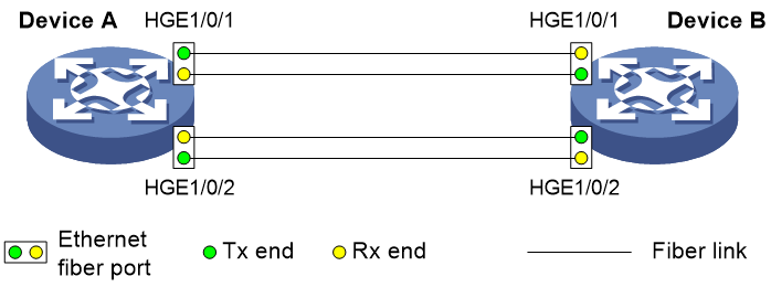
Figure 2 shows a correct fiber connection and two types of unidirectional fiber connections.
Figure 2 Correct and incorrect fiber connections
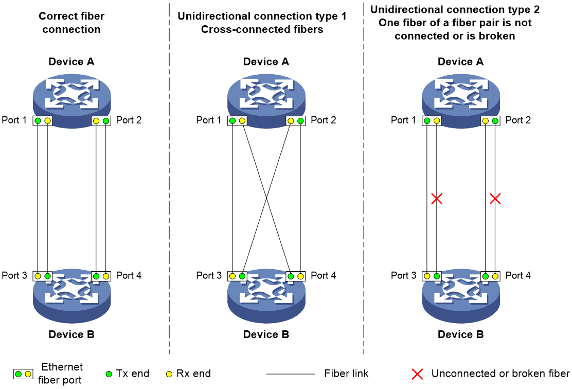
Physical layer detection mechanisms, such as auto-negotiation, can detect physical signals and faults. However, they cannot detect communication failures for unidirectional links where the physical layer is in connected state.
As a data link layer protocol, the Device Link Detection Protocol (DLDP) detects the following:
· Whether the fiber link or twisted-pair link is correctly connected at the link layer.
· Whether the two ends of the link can exchange packets correctly.
When DLDP detects unidirectional links, it can automatically shut down the faulty port to avoid network problems. Alternatively, a user can manually shut down the faulty port. DLDP cooperates with physical layer protocols to monitor link status and avoid physical and logical unidirectional links.
Basic concepts
DLDP neighbor states
If port A can receive link-layer packets from port B on the same link, port B is a DLDP neighbor of port A. Two ports that can exchange packets are neighbors.
Table 4 DLDP neighbor states
|
DLDP timer |
Description |
|
Confirmed |
The link to a DLDP neighbor is bidirectional. |
|
Unconfirmed |
The state of the link to a newly discovered neighbor is not determined. |
DLDP port states
A DLDP-enabled port is called a DLDP port. A DLDP port can have multiple neighbors, and its state varies by the DLDP neighbor state.
Table 5 DLDP port states
|
State |
Description |
|
Initial |
DLDP is enabled on the port, but is disabled globally. |
|
Inactive |
DLDP is enabled on the port and globally, and the link is physically down. |
|
Bidirectional |
DLDP is enabled on the port and globally, and at least one neighbor in Confirmed state exists. |
|
Unidirectional |
DLDP is enabled on the port and globally, and no neighbor in Confirmed state exists. In this state, a port does not send or receive packets other than DLDP packets any more. |
DLDP timers
Table 6 DLDP timers
|
DLDP timer |
Description |
|
Advertisement timer |
Advertisement packet sending interval (the default is 5 seconds and is configurable). |
|
Probe timer |
Probe packet sending interval. This timer is set to 1 second. |
|
Echo timer |
The Echo timer is triggered when a probe is launched for a new neighbor. This timer is set to 10 seconds. |
|
Entry timer |
When a new neighbor joins, a neighbor entry is created and the corresponding entry timer is triggered if the neighbor is in Confirmed state. When an Advertisement is received, the device updates the corresponding neighbor entry and the Entry timer. The setting of an Entry timer is three times that of the Advertisement timer. |
|
Enhanced timer |
The Enhanced timer is triggered, together with the Echo timer, when the Entry timer expires. The Enhanced timer is set to 1 second. |
|
DelayDown timer |
If a port is physically down, the device triggers the DelayDown timer, rather than removing the corresponding neighbor entry. The default DelayDown timer is 1 second and is configurable. When the DelayDown timer expires, the device removes the corresponding DLDP neighbor information if the port is down, and does not perform any operation if the port is up. |
|
RecoverProbe timer |
This timer is set to 2 seconds. A port in Unidirectional state regularly sends RecoverProbe packets to detect whether a unidirectional link has been restored to bidirectional. |
DLDP authentication mode
You can use DLDP authentication to prevent network attacks and illegal detecting.
Table 7 DLDP authentication mode
|
Authentication mode |
Processing at the DLDP packet sending side |
Processing at the DLDP packet receiving side |
|
Non-authentication |
The sending side sets the Authentication field of DLDP packets to 0. |
The receiving side examines the authentication information of received DLDP packets and drops packets where the authentication information conflicts with the local configuration. |
|
Plaintext authentication |
The sending side sets the Authentication field to the password configured in plain text. |
|
|
MD5 authentication |
The sending side encrypts the user configured password by using MD5 algorithm, and assigns the digest to the Authentication field. |
How DLDP works
Detecting one neighbor
When two devices are connected through an optical fiber or a network cable, enable DLDP to detect unidirectional links to the neighbor. The following illustrates the unidirectional link detection process in two cases:
· Unidirectional links occur before you enable DLDP.
Figure 3 Cross-connected fibers
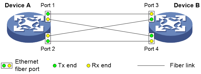
As shown in Figure 3, before you enable DLDP, the optical fibers between Device A and Device B are cross-connected. After you enable DLDP, the four ports are all up and in Unidirectional state, and they send RecoverProbe packets. Take Port 1 as an example to illustrate the unidirectional link detection process.
a. Port 1 receives the RecoverProbe packet from Port 4, and returns a RecoverEcho packet.
b. Port 4 cannot receive any RecoverEcho packet from Port 1, so Port 4 cannot become the neighbor of Port 1.
c. Port 3 can receive the RecoverEcho packet from Port 1, but Port 3 is not the intended destination, so Port 3 cannot become the neighbor of Port 1.
The same process occurs on the other three ports. The four ports are all in Unidirectional state.
· Unidirectional links occur after you enable DLDP.
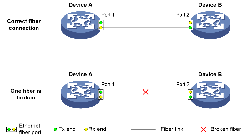
As shown in Figure 4, Device A and Device B are connected through an optical fiber. After you enable DLDP, Port 1 and Port 2 establish the bidirectional neighborship in the following way:
a. Port 1 that is physically up enters the Unidirectional state and sends a RecoverProbe packet.
b. After receiving the RecoverProbe packet, Port 2 returns a RecoverEcho packet.
c. After Port 1 receives the RecoverEcho packet, it examines the neighbor information in the packet. If the neighbor information matches the local information, Port 1 establishes the neighborship with Port 2 and transits to Bidirectional state. Port 1 then starts the Entry timer and periodically sends Advertisement packets.
d. After Port 2 receives the Advertisement packet, it establishes the Unconfirmed neighborship with Port 1. Port 2 then starts the Echo timer and Probe timer, and periodically sends Probe packets.
e. After receiving the Probe packet, Port 1 returns an Echo packet.
f. After Port 2 receives the Echo packet, it examines the neighbor information in the packet. If the neighbor information matches the local information, the neighbor state of Port 1 becomes Confirmed. Port 2 then transits to Bidirectional state, starts the Entry timer, and periodically sends Advertisement packets.
The bidirectional neighborship between Port 1 and Port 2 is now established.
After that, when Port 2's Rx end fails to receive signals, Port 2 is physically down and enters the Inactive state. Because Port 2's Tx end can still send signals to Port 1, Port 1 stays up. After the Entry timer for Port 2 expires, Port 1 starts the Enhanced timer and Echo timer, and sends a probe packet to Port 2. Because Port 1's Tx line is broken, Port 1 cannot receive the Echo packet from Port 2 after the Echo timer expires. Port 1 then enters the Unidirectional state, and sends a Disable packet to Port 2. At the same time, Port 1 deletes the neighborship with Port 2, and starts the RecoverProbe timer. Port 2 stays in Inactive state during this process.
When an interface is physically down, but the Tx end of the interface is still operating, DLDP sends a LinkDown packet to inform the peer to delete the relevant neighbor entry.
Detecting multiple neighbors
When multiple devices are connected through a hub, enable DLDP on all interfaces connected to the hub to detect unidirectional links among the neighbors. When no Confirmed neighbor exists, an interface enters the Unidirectional state.
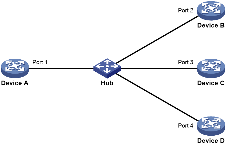
As shown in Figure 5, Device A through Device D are connected through a hub, and enabled with DLDP. When Ports 1, 2, and 3 detect that the link to Port 4 fails, they delete the neighborship with Port 4, but stay in Bidirectional state.
Configuration restrictions and guidelines
When you configure DLDP, follow these configuration restrictions and guidelines:
· For DLDP to operate correctly, enable DLDP on both sides and make sure the following settings are consistent:
¡ Interval to send Advertisement packets.
¡ DLDP authentication mode.
¡ Password.
· For DLDP to operate correctly, configure the full duplex mode for the ports at the two ends of the link, and configure the same speed for the two ports.
DLDP configuration task list
|
Tasks at a glance |
|
(Required.) Enabling DLDP |
|
(Optional.) Setting the interval to send advertisement packets |
|
(Optional.) Setting the DelayDown timer |
|
(Optional.) Setting the port shutdown mode |
|
(Optional.) Configuring DLDP authentication |
Enabling DLDP
To correctly configure DLDP on the device, you must enable DLDP globally and on each port.
To enable DLDP:
|
Command |
Remarks |
|
|
1. Enter system view. |
system-view |
N/A |
|
2. Enable DLDP globally. |
dldp global enable |
By default, DLDP is globally disabled. |
|
3. Enter Ethernet interface view. |
interface interface-type interface-number |
N/A |
|
4. Enable DLDP. |
dldp enable |
By default, DLDP is disabled on an interface. |
Setting the interval to send advertisement packets
To make sure DLDP can detect unidirectional links before network performance deteriorates, set the advertisement interval appropriate for your network environment. As a best practice, use the default interval.
To set the Advertisement packet sending interval:
|
Step |
Command |
Remarks |
|
1. Enter system view. |
system-view |
N/A |
|
2. Set the interval to send Advertisement packets. |
dldp interval interval |
By default, the interval is 5 seconds. |
Setting the DelayDown timer
When the Tx line fails, some ports might go down and then come up again, causing optical signal jitters on the Rx line. To prevent the device from removing neighbor entries in such cases, set the DelayDown timer for the device. The device starts the DelayDown timer when a port goes down due to a Tx line failure. If the port remains down when the timer expires, the device removes the DLDP neighbor information. If the port comes up, the device takes no action.
To set the DelayDown timer:
|
Step |
Command |
Remarks |
|
1. Enter system view. |
system-view |
N/A |
|
2. Set the DelayDown timer. |
dldp delaydown-timer time |
The default is 1 second. The DelayDown timer setting applies to all DLDP-enabled ports. |
Setting the port shutdown mode
On detecting a unidirectional link, DLDP shuts down the ports in one of the following modes:
· Auto mode—When a unidirectional link is detected, DLDP changes the DLDP port state to Unidirectional. The unidirectional port periodically sends RecoverProbe packets. When a correct RecoverEcho packet is received, the link is restored to a bidirectional link, and the port state changes from Unidirectional to Bidirectional. This process is called link auto-recovery mechanism.
· Manual mode—When a unidirectional link is detected, DLDP does not shut down the port, and you need to manually shut it down. When the link state is restored to Bidirectional, you must manually bring up the port. Use this mode to prevent normal links from being shut down because of false unidirectional link reports in the following cases:
¡ The network performance is low.
¡ The device is busy.
¡ The CPU usage is high.
To enable remote OAM loopback on a DLDP port, set the port shutdown mode to manual. Otherwise, DLDP automatically shuts down the port when it receives a packet sent by itself. This causes remote OAM loopback failure. For more information about Ethernet OAM, see "Configuring Ethernet OAM."
To set port shutdown mode:
|
Step |
Command |
Remarks |
|
1. Enter system view. |
system-view |
N/A |
|
2. Set port shutdown mode. |
dldp unidirectional-shutdown { auto | manual } |
The default mode is auto. |
Configuring DLDP authentication
You can guard your network against attacks and malicious probes by configuring an appropriate DLDP authentication mode, which can be plain text authentication or MD5 authentication. If your network is safe, you can choose not to authenticate.
To configure DLDP authentication:
|
Step |
Command |
Remarks |
|
1. Enter system view. |
system-view |
N/A |
|
2. Configure a DLDP authentication mode. |
dldp authentication-mode { md5 | none | simple } |
The default authentication mode is none. |
|
3. Configure the password for DLDP authentication. |
dldp authentication-password { cipher | simple } string |
By default, no password is configured for DLDP authentication. If you do not configure the authentication password after you configure the authentication mode, the authentication mode is none no matter which authentication mode you configure. |
Displaying and maintaining DLDP
Execute display commands in any view and the reset command in user view.
|
Task |
Command |
|
Display the DLDP configuration globally and of a port. |
display dldp [ interface interface-type interface-number ] |
|
Display the statistics on DLDP packets passing through a port. |
display dldp statistics [ interface interface-type interface-number ] |
|
Clear the statistics on DLDP packets passing through a port. |
reset dldp statistics [ interface interface-type interface-number ] |
DLDP configuration examples
Automatically shutting down unidirectional links
Network requirements
As shown in Figure 6, Device A and Device B are connected through two fiber pairs.
Configure DLDP to automatically shut down the faulty port upon detecting a unidirectional link, and automatically bring up the port after you clear the fault.
Configuration procedure
1. Configure Device A:
# Enable DLDP globally.
<DeviceA> system-view
[DeviceA] dldp global enable
# Configure HundredGigE 1/0/1 to operate in full duplex mode and at 100000 Mbps, and enable DLDP on the port.
[DeviceA] interface hundredgige 1/0/1
[DeviceA-HundredGigE1/0/1] duplex full
[DeviceA-HundredGigE1/0/1] speed 100000
[DeviceA-HundredGigE1/0/1] dldp enable
[DeviceA-HundredGigE1/0/1] quit
# Configure HundredGigE 1/0/2 to operate in full duplex mode and at 100000 Mbps, and enable DLDP on the port.
[DeviceA] interface hundredgige 1/0/2
[DeviceA-HundredGigE1/0/2] duplex full
[DeviceA-HundredGigE1/0/2] speed 100000
[DeviceA-HundredGigE1/0/2] dldp enable
[DeviceA-HundredGigE1/0/2] quit
# Set the port shutdown mode to auto.
[DeviceA] dldp unidirectional-shutdown auto
2. Configure Device B:
# Enable DLDP globally.
<DeviceB> system-view
[DeviceB] dldp global enable
# Configure HundredGigE 1/0/1 to operate in full duplex mode and at 100000 Mbps, and enable DLDP on it.
[DeviceB] interface hundredgige 1/0/1
[DeviceB-HundredGigE1/0/1] duplex full
[DeviceB-HundredGigE1/0/1] speed 100000
[DeviceB-HundredGigE1/0/1] dldp enable
[DeviceB-HundredGigE1/0/1] quit
# Configure HundredGigE 1/0/2 to operate in full duplex mode and at 100000 Mbps, and enable DLDP on it.
[DeviceB] interface hundredgige 1/0/2
[DeviceB-HundredGigE1/0/2] duplex full
[DeviceB-HundredGigE1/0/2] speed 100000
[DeviceB-HundredGigE1/0/2] dldp enable
[DeviceB-HundredGigE1/0/2] quit
# Set the port shutdown mode to auto.
[DeviceB] dldp unidirectional-shutdown auto
3. Verify the configuration:
# Display the DLDP configuration globally and on all the DLDP-enabled ports of Device A.
[DeviceA] display dldp
DLDP global status: Enabled
DLDP advertisement interval: 5s
DLDP authentication-mode: None
DLDP unidirectional-shutdown mode: Auto
DLDP delaydown-timer value: 1s
Number of enabled ports: 2
Interface HundredGigE1/0/1
DLDP port state: Bidirectional
Number of the port’s neighbors: 1
Neighbor MAC address: 0023-8956-3600
Neighbor port index: 1
Neighbor state: Confirmed
Neighbor aged time: 11s
Interface HundredGigE1/0/2
DLDP port state: Bidirectional
Number of the port’s neighbors: 1
Neighbor MAC address: 0023-8956-3600
Neighbor port index: 2
Neighbor state: Confirmed
Neighbor aged time: 12s
The output shows that both HundredGigE 1/0/1 and HundredGigE 1/0/2 are bidirectional.
# Enable the monitoring of logs on the current terminal on Device A. Set the lowest level of the logs that can be output to the current terminal to 6.
[DeviceA] quit
<DeviceA> terminal monitor
<DeviceA> terminal logging level 6
The following log information is displayed on Device A:
<DeviceA>%Jul 11 17:40:31:089 2012 DeviceA IFNET/3/PHY_UPDOWN: HundredGigE1/0/1 link status is DOWN.
%Jul 11 17:40:31:091 2012 DeviceA IFNET/5/LINK_UPDOWN: Line protocol on the interface HundredGigE1/0/1 is DOWN.
%Jul 11 17:40:31:677 2012 DeviceA IFNET/3/PHY_UPDOWN: HundredGigE1/0/2 link status is DOWN.
%Jul 11 17:40:31:678 2012 DeviceA IFNET/5/LINK_UPDOWN: Line protocol on the interface HundredGigE1/0/2 is DOWN.
%Jul 11 17:40:38:544 2012 DeviceA IFNET/3/PHY_UPDOWN: HundredGigE1/0/1 link status is UP.
%Jul 11 17:40:38:836 2012 DeviceA IFNET/3/PHY_UPDOWN: HundredGigE1/0/2 link status is UP.
The output shows the following:
¡ The port status of both HundredGigE 1/0/1 and HundredGigE 1/0/2 is down and then up.
¡ The link status of both HundredGigE 1/0/1 and HundredGigE 1/0/2 is always down.
# Display the DLDP configuration globally and of all the DLDP-enabled ports.
<DeviceA> display dldp
DLDP global status: Enabled
DLDP advertisement interval: 5s
DLDP authentication-mode: None
DLDP unidirectional-shutdown mode: Auto
DLDP delaydown-timer value: 1s
Number of enabled ports: 2
Interface HundredGigE1/0/1
DLDP port state: Unidirectional
Number of the port’s neighbors: 0 (Maximum number ever detected: 1)
Interface HundredGigE1/0/2
DLDP port state: Unidirectional
Number of the port’s neighbors: 0 (Maximum number ever detected: 1)
The output shows that the DLDP port status of both HundredGigE 1/0/1 and HundredGigE 1/0/2 is unidirectional. DLDP detects unidirectional links on them and automatically shuts down the two ports.
The unidirectional links are caused by cross-connected fibers. Correct the fiber connections. As a result, the ports shut down by DLDP automatically recover, and Device A displays the following log information:
<DeviceA>%Jul 11 17:42:57:709 2012 DeviceA IFNET/3/PHY_UPDOWN: HundredGigE1/0/1 link status is DOWN.
%Jul 11 17:42:58:603 2012 DeviceA IFNET/3/PHY_UPDOWN: HundredGigE1/0/2 link status is DOWN.
%Jul 11 17:43:02:342 2012 DeviceA IFNET/3/PHY_UPDOWN: HundredGigE1/0/1 link status is UP.
%Jul 11 17:43:02:343 2012 DeviceA DLDP/6/DLDP_NEIGHBOR_CONFIRMED: A neighbor was confirmed on interface HundredGigE1/0/1. The neighbor's system MAC is 0023-8956-3600, and the port index is 1.
%Jul 11 17:43:02:344 2012 DeviceA DLDP/6/DLDP_LINK_BIDIRECTIONAL: DLDP detected a bidirectional link on interface HundredGigE1/0/1.
%Jul 11 17:43:02:353 2012 DeviceA IFNET/5/LINK_UPDOWN: Line protocol on the interface HundredGigE1/0/1 is UP.
%Jul 11 17:43:02:357 2012 DeviceA IFNET/3/PHY_UPDOWN: HundredGigE1/0/2 link status is UP.
%Jul 11 17:43:02:362 2012 DeviceA DLDP/6/DLDP_NEIGHBOR_CONFIRMED: A neighbor was confirmed on interface HundredGigE1/0/2. The neighbor's system MAC is 0023-8956-3600, and the port index is 2.
%Jul 11 17:43:02:362 2012 DeviceA DLDP/6/DLDP_LINK_BIDIRECTIONAL: DLDP detected a bidirectional link on interface HundredGigE1/0/2.
%Jul 11 17:43:02:368 2012 DeviceA IFNET/5/LINK_UPDOWN: Line protocol on the interface HundredGigE1/0/2 is UP.
The output shows that the port status and link status of both HundredGigE 1/0/1 and HundredGigE 1/0/2 are now up and their DLDP neighbors are determined.
Manually shutting down unidirectional links
Network requirements
As shown in Figure 7, Device A and Device B are connected through two fiber pairs.
Configure DLDP to detect unidirectional links. When a unidirectional link is detected, the administrator must manually shut down the port.

Configuration procedure
1. Configure Device A:
# Enable DLDP globally.
<DeviceA> system-view
[DeviceA] dldp enable
# Configure HundredGigE 1/0/1 to operate in full duplex mode and at 100000 Mbps, and enable DLDP on the port.
[DeviceA] interface hundredgige 1/0/1
[DeviceA-HundredGigE1/0/1] duplex full
[DeviceA-HundredGigE1/0/1] speed 100000
[DeviceA-HundredGigE1/0/1] dldp enable
[DeviceA-HundredGigE1/0/1] quit
# Configure HundredGigE 1/0/2 to operate in full duplex mode and at 100000 Mbps, and enable DLDP on the port.
[DeviceA] interface hundredgige 1/0/2
[DeviceA-HundredGigE1/0/2] duplex full
[DeviceA-HundredGigE1/0/2] speed 100000
[DeviceA-HundredGigE1/0/2] dldp enable
[DeviceA-HundredGigE1/0/2] quit
# Set the port shutdown mode to manual.
[DeviceA] dldp unidirectional-shutdown manual
2. Configure Device B:
# Enable DLDP globally.
<DeviceB> system-view
[DeviceB] dldp global enable
# Configure HundredGigE 1/0/1 to operate in full duplex mode and at 100000 Mbps, and enable DLDP on it.
[DeviceB] interface hundredgige 1/0/1
[DeviceB-HundredGigE1/0/1] duplex full
[DeviceB-HundredGigE1/0/1] speed 100000
[DeviceB-HundredGigE1/0/1] dldp enable
[DeviceB-HundredGigE1/0/1] quit
# Configure HundredGigE 1/0/2 to operate in full duplex mode and at 100000 Mbps, and enable DLDP on it.
[DeviceB] interface hundredgige 1/0/2
[DeviceB-HundredGigE1/0/2] duplex full
[DeviceB-HundredGigE1/0/2] speed 100000
[DeviceB-HundredGigE1/0/2] dldp enable
[DeviceB-HundredGigE1/0/2] quit
# Set the port shutdown mode to manual.
[DeviceB] dldp unidirectional-shutdown manual
3. Verify the configuration:
# Display the DLDP configuration globally and on all the DLDP-enabled ports of Device A.
[DeviceA] display dldp
DLDP global status: Enabled
DLDP advertisement interval: 5s
DLDP authentication-mode: None
DLDP unidirectional-shutdown mode: Manual
DLDP delaydown-timer value: 1s
Number of enabled ports: 2
Interface HundredGigE1/0/1
DLDP port state: Bidirectional
Number of the port’s neighbors: 1
Neighbor MAC address: 0023-8956-3600
Neighbor port index: 1
Neighbor state: Confirmed
Neighbor aged time: 11s
Interface HundredGigE1/0/2
DLDP port state: Bidirectional
Number of the port’s neighbors: 1
Neighbor MAC address: 0023-8956-3600
Neighbor port index: 2
Neighbor state: Confirmed
Neighbor aged time: 12s
The output shows that both HundredGigE 1/0/1 and HundredGigE 1/0/2 are in Bidirectional state, which means both links are bidirectional.
# Enable the monitoring of logs on the current terminal on Device A. Set the lowest level of the logs that can be output to the current terminal to 6.
[DeviceA] quit
<DeviceA> terminal monitor
<DeviceA> terminal logging level 6
The following log information is displayed on Device A:
<DeviceA>%Jul 12 08:29:17:786 2012 DeviceA IFNET/3/PHY_UPDOWN: HundredGigE1/0/1 link status is DOWN.
%Jul 12 08:29:17:787 2012 DeviceA IFNET/5/LINK_UPDOWN: Line protocol on the interface HundredGigE1/0/1 is DOWN.
%Jul 12 08:29:17:800 2012 DeviceA IFNET/3/PHY_UPDOWN: HundredGigE1/0/2 link status is DOWN.
%Jul 12 08:29:17:800 2012 DeviceA IFNET/5/LINK_UPDOWN: Line protocol on the interface HundredGigE1/0/2 is DOWN.
%Jul 12 08:29:25:004 2012 DeviceA IFNET/3/PHY_UPDOWN: HundredGigE1/0/1 link status is UP.
%Jul 12 08:29:25:005 2012 DeviceA IFNET/5/LINK_UPDOWN: Line protocol on the interface HundredGigE1/0/1 is UP.
%Jul 12 08:29:25:893 2012 DeviceA IFNET/3/PHY_UPDOWN: HundredGigE1/0/2 link status is UP.
%Jul 12 08:29:25:894 2012 DeviceA IFNET/5/LINK_UPDOWN: Line protocol on the interface HundredGigE1/0/2 is UP.
The output shows that the port status and link status of both HundredGigE 1/0/1 and HundredGigE 1/0/2 are down and then up.
# Display the DLDP configuration globally and of all the DLDP-enabled ports.
<DeviceA> display dldp
DLDP global status: Enabled
DLDP advertisement interval: 5s
DLDP authentication-mode: None
DLDP unidirectional-shutdown mode: Manual
DLDP delaydown-timer value: 1s
Number of enabled ports: 2
Interface HundredGigE1/0/1
DLDP port state: Unidirectional
Number of the port’s neighbors: 0 (Maximum number ever detected: 1)
Interface HundredGigE1/0/2
DLDP port state: Unidirectional
Number of the port’s neighbors: 0 (Maximum number ever detected: 1)
The output shows that the DLDP port status of both HundredGigE 1/0/1 and HundredGigE 1/0/2 is unidirectional. DLDP detects unidirectional links on the two ports but does not shut them down.
The unidirectional links are caused by cross-connected fibers. Manually shut down the two ports:
# Shut down HundredGigE 1/0/1.
<DeviceA> system-view
[DeviceA] interface hundredgige 1/0/1
[DeviceA-HundredGigE1/0/1] shutdown
The following log information is displayed on Device A:
[DeviceA-HundredGigE1/0/1]%Jul 12 08:34:23:717 2012 DeviceA IFNET/3/PHY_UPDOWN: HundredGigE1/0/1 link status is DOWN.
%Jul 12 08:34:23:718 2012 DeviceA IFNET/5/LINK_UPDOWN: Line protocol on the interface HundredGigE1/0/1 is DOWN.
%Jul 12 08:34:23:778 2012 DeviceA IFNET/3/PHY_UPDOWN: HundredGigE1/0/2 link status is DOWN.
%Jul 12 08:34:23:779 2012 DeviceA IFNET/5/LINK_UPDOWN: Line protocol on the interface HundredGigE1/0/2 is DOWN.
The output shows that the port status and link status of both HundredGigE 1/0/1 and HundredGigE 1/0/2 are now down.
# Shut down HundredGigE 1/0/2.
[DeviceA-HundredGigE1/0/1] quit
[DeviceA] interface hundredgige 1/0/2
[DeviceA-HundredGigE1/0/2] shutdown
Correct the fiber connections and bring up the two ports:
# Bring up HundredGigE 1/0/2.
[DeviceA-HundredGigE1/0/2] undo shutdown
The following log information is displayed on Device A:
[DeviceA-HundredGigE1/0/2]%Jul 12 08:46:17:677 2012 DeviceA IFNET/3/PHY_UPDOWN: HundredGigE1/0/2 link status is UP.
%Jul 12 08:46:17:678 2012 DeviceA IFNET/5/LINK_UPDOWN: Line protocol on the interface HundredGigE1/0/2 is UP.
%Jul 12 08:46:17:959 2012 DeviceA DLDP/6/DLDP_NEIGHBOR_CONFIRMED: A neighbor was confirmed on interface HundredGigE1/0/2. The neighbor's system MAC is 0023-8956-3600, and the port index is 2.
%Jul 12 08:46:17:959 2012 DeviceA DLDP/6/DLDP_LINK_BIDIRECTIONAL: DLDP detected a bidirectional link on interface HundredGigE1/0/2.
The output shows that the port status and link status of HundredGigE 1/0/2 are now up and its DLDP neighbors are determined.
# Bring up HundredGigE 1/0/1.
[DeviceA-HundredGigE1/0/2] quit
[DeviceA] interface hundredgige 1/0/1
[DeviceA-HundredGigE1/0/1] undo shutdown
The following log information is displayed on Device A:
[DeviceA-HundredGigE1/0/1]%Jul 12 08:48:25:952 2012 DeviceA IFNET/3/PHY_UPDOWN: HundredGigE1/0/1 link status is UP.
%Jul 12 08:48:25:952 2012 DeviceA DLDP/6/DLDP_NEIGHBOR_CONFIRMED: A neighbor was confirmed on interface HundredGigE1/0/1. The neighbor's system MAC is 0023-8956-3600, and the port index is 1.
%Jul 12 08:48:25:953 2012 DeviceA IFNET/5/LINK_UPDOWN: Line protocol on the interface HundredGigE1/0/1 is UP.
%Jul 12 08:48:25:953 2012 DeviceA DLDP/6/DLDP_LINK_BIDIRECTIONAL: DLDP detected a bidirectional link on interface HundredGigE1/0/1.
The output shows that the port status and link status of HundredGigE 1/0/1 are now up and its DLDP neighbors are determined.
Configuring RRPP
Overview
Metropolitan area networks (MANs) and enterprise networks typically use the ring topology to improve reliability. However, services will be interrupted if any node in the ring network fails. A ring network typically uses RPR or Ethernet rings. RPR is high in cost because it needs dedicated hardware. In contrast, the Ethernet ring technology is more mature and economical, so it is more and more popular in MANs and enterprise networks.
The Rapid Ring Protection Protocol (RRPP) is a link layer protocol designed for Ethernet rings. RRPP can prevent broadcast storms caused by data loops when an Ethernet ring is healthy. RRPP can also rapidly restore the communication paths between the nodes when a link is disconnected on the ring. The convergence time of RRPP is independent of the number of nodes in the Ethernet ring. RRPP is applicable to large-diameter networks.
Basic RRPP concepts
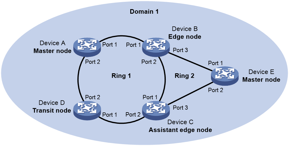
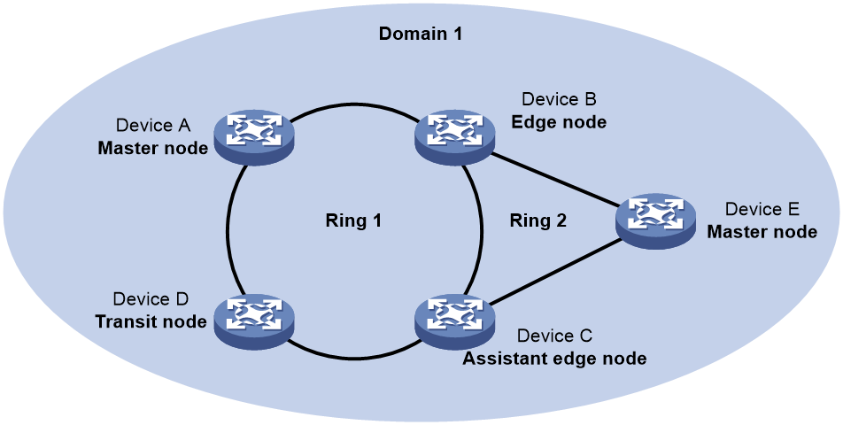
Figure 8 shows a typical RRPP network with two Ethernet rings and multiple nodes. RRPP detects ring status and sends topology change information by exchanging Rapid Ring Protection Protocol Data Units (RRPPDUs) among the nodes.
Figure 8 RRPP networking diagram
RRPP domain
An RRPP domain is uniquely identified by a domain ID. The interconnected devices with the same domain ID and control VLANs constitute an RRPP domain. An RRPP domain contains the following elements:
· Primary ring and subring.
· Control VLAN.
· Master node, transit node, edge node, and assistant edge node.
· Primary port, secondary port, common port, and edge port.
As shown in Figure 8, Domain 1 is an RRPP domain, containing two RRPP rings: Ring 1 and Ring 2. All the nodes on the two RRPP rings belong to the RRPP domain.
RRPP ring
A ring-shaped Ethernet topology is called an RRPP ring. RRPP rings include primary rings and subrings. You can configure a ring as either the primary ring or a subring by specifying its ring level. The primary ring is of level 0, and a subring is of level 1. An RRPP domain contains one or multiple RRPP rings, one serving as the primary ring and the others serving as subrings. A ring can be in one of the following states:
· Health state—All physical links on the Ethernet ring are connected.
· Disconnect state—Some physical links on the Ethernet ring are not connected.
As shown in Figure 8, Domain 1 contains two RRPP rings: Ring 1 and Ring 2. The level is set to 0 for Ring 1 and 1 for Ring 2. Ring 1 is configured as the primary ring, and Ring 2 is configured as a subring.
Control VLAN and protected VLAN
1. Control VLAN
In an RRPP domain, a control VLAN is dedicated to transferring RRPPDUs. On a device, the ports accessing an RRPP ring belong to the control VLANs of the ring, and only these ports can join the control VLANs.
An RRPP domain is configured with the following control VLANs:
¡ One primary control VLAN, which is the control VLAN for the primary ring.
¡ One secondary control VLAN, which is the control VLAN for subrings.
After you specify a VLAN as the primary control VLAN, the system automatically configures the secondary control VLAN. The VLAN ID is the primary control VLAN ID plus one. All subrings in the same RRPP domain share the same secondary control VLAN. IP address configuration is prohibited on the control VLAN interfaces.
2. Protected VLAN
A protected VLAN is dedicated to transferring data packets. Both RRPP ports and non-RRPP ports can be assigned to a protected VLAN.
Node
Each device on an RRPP ring is a node. The role of a node is configurable. RRPP has the following node roles:
· Master node—Each ring has only one master node. The master node initiates the polling mechanism and determines the operations to be performed after a topology change.
· Transit node—On the primary ring, transit nodes refer to all nodes except the master node. On the subring, transit nodes refer to all nodes except the master node and the nodes where the primary ring intersects with the subring. A transit node monitors the state of its directly connected RRPP links and notifies the master node of the link state changes, if any. Based on the link state changes, the master node determines the operations to be performed.
· Edge node—A special node residing on both the primary ring and a subring at the same time. An edge node acts as a master node or transit node on the primary ring and as an edge node on the subring.
· Assistant edge node—A special node residing on both the primary ring and a subring at the same time. An assistant edge node acts as a master node or transit node on the primary ring and as an assistant edge node on the subring. This node works in conjunction with the edge node to detect the integrity of the primary ring and to perform loop guard.
As shown in Figure 8, Ring 1 is the primary ring and Ring 2 is a subring. Device A is the master node of Ring 1. Device B, Device C, and Device D are the transit nodes of Ring 1. Device E is the master node of Ring 2, Device B is the edge node of Ring 2, and Device C is the assistant edge node of Ring 2.
Port
1. Primary port and secondary port
Each master node or transit node has two ports connected to an RRPP ring, a primary port and a secondary port. You can determine the role of a port.
In terms of functionality, the primary port and the secondary port of a master node have the following differences:
¡ The primary port and the secondary port are designed to play the role of sending and receiving Hello packets, respectively.
¡ When an RRPP ring is in Health state, the secondary port logically denies protected VLANs and permits only the packets from the control VLANs.
¡ When an RRPP ring is in Disconnect state, the secondary port forwards packets from protected VLANs.
In terms of functionality, the primary port and the secondary port of a transit node are the same. Both are designed for transferring protocol packets and data packets over an RRPP ring.
As shown in Figure 8, Device A is the master node of Ring 1. Port 1 and Port 2 are the primary port and the secondary port of the master node on Ring 1, respectively. Device B, Device C, and Device D are the transit nodes of Ring 1. Their Port 1 and Port 2 are the primary port and the secondary port on Ring 1, respectively.
2. Common port and edge port
The ports connecting the edge node and assistant edge node to the primary ring are common ports. The ports connecting the edge node and assistant edge node only to the subrings are edge ports. You can determine the role of a port.
As shown in Figure 8, Device B and Device C reside on Ring 1 and Ring 2. Device B's Port 1 and Port 2 and Device C's Port 1 and Port 2 access the primary ring, so they are common ports. Device B's Port 3 and Device C's Port 3 access only the subring, so they are edge ports.
RRPP ring group
To reduce Edge-Hello traffic, you can configure a group of subrings on the edge node or assistant edge node. You must configure a device as the edge node of these subrings, and another device as the assistant edge node of these subrings. Additionally, the subrings of the edge node and assistant edge node must connect to the same subring packet tunnels in major ring (SRPTs). Edge-Hello packets of the edge node of these subrings travel to the assistant edge node of these subrings over the same link.
An RRPP ring group configured on the edge node is an edge node RRPP ring group. An RRPP ring group configured on an assistant edge node is an assistant edge node RRPP ring group. Only one subring in an edge node RRPP ring group is allowed to send Edge-Hello packets.
RRPPDUs
Table 8 RRPPDU types and their functions
|
Type |
Description |
|
Hello |
The master node sends Hello packets (also known as Health packets) to detect the integrity of a ring in a network. |
|
Link-Down |
When a port on the transit node, edge node, or assistant edge node fails, the node initiates Link-Down packets to notify the master node of the disconnection of the ring. |
|
Common-Flush-FDB |
When an RRPP ring transits to Disconnect state, the master node initiates Common-Flush-FDB (FDB stands for Forwarding Database) packets. It uses the packets to instruct the transit nodes, edge nodes, and assistant edge nodes to update their own MAC address entries and ARP/ND entries. |
|
Complete-Flush-FDB |
When an RRPP ring transits to Health state, the master node sends Complete-Flush-FDB packets for the following purposes: · Instruct the transit nodes, edge nodes, and assistant edge nodes to update their MAC address entries and ARP/ND entries. · Instruct the transit nodes to unblock temporarily blocked ports. |
|
Edge-Hello |
The edge node sends Edge-Hello packets to examine the SRPTs between the edge node and the assistant edge node. |
|
Major-Fault |
The assistant edge node sends Major-Fault packets to notify the edge node of SRPT failure when an SRPT between assistant edge node and edge node is disconnected. |
RRPP timers
When RRPP determines the link state of an Ethernet ring, it uses the following timers:
· Hello timer—Specifies the interval at which the master node sends Hello packets out of the primary port.
· Fail timer—Specifies the maximum delay of Hello packets sent from the primary port to the secondary port of the master node. If the secondary port receives the Hello packets sent by the local master node before the Fail timer expires, the ring is in Health state. Otherwise, the ring transits to Disconnect state.
In an RRPP domain, a transit node learns the Fail timer value on the master node through the received Hello packets. This ensures that all nodes in the ring network have consistent Fail timer settings.
How RRPP works
Polling mechanism
The polling mechanism is used by the master node of an RRPP ring to examine the Health state of the ring network.
The master node sends Hello packets out of its primary port at the Hello interval. These Hello packets travel through each transit node on the ring in turn.
· If the ring is complete, the secondary port of the master node receives Hello packets before the Fail timer expires. The master node keeps the secondary port blocked.
· If the ring is disconnected, the secondary port of the master node fails to receive Hello packets before the Fail timer expires. The master node releases the secondary port from blocking protected VLANs. It sends Common-Flush-FDB packets to instruct all transit nodes to update their own MAC address entries and ARP/ND entries.
Load balancing
In a ring network, traffic from multiple VLANs might be transmitted at the same time. RRPP can implement load balancing by transmitting traffic from different VLANs along different paths.
You can configure multiple RRPP domains for a ring network. Each RRPP domain transmits the traffic from the specified VLANs (protected VLANs). Traffic from different VLANs can be transmitted according to different topologies in the ring network for load balancing.
As shown in Figure 13, Ring 1 is configured as the primary ring of Domain 1 and Domain 2, which are configured with different protected VLANs. Device A is the master node of Ring 1 in Domain 1. Device B is the master node of Ring 1 in Domain 2. With such configurations, traffic from different VLANs can be transmitted on different links for load balancing in the single-ring network.
Link down alarm mechanism
In an RRPP domain, when the transit node, edge node, or assistant edge node finds that any of its ports is down, it immediately sends Link-Down packets to the master node. When the master node receives a Link-Down packet, it takes the following actions:
· Releases the secondary port from blocking protected VLANs.
· Sends Common-Flush-FDB packets to instruct all the transit nodes, edge nodes, and assistant edge nodes to update their MAC address entries and ARP/ND entries.
After each node updates its own entries, traffic is switched to the normal link.
Ring recovery
When the ports in an RRPP domain on the transit nodes, edge nodes, or assistant edge nodes come up again, the ring is recovered. However, the master node might detect the ring recovery after a period of time. A temporary loop might arise in the protected VLAN during this period. As a result, a broadcast storm occurs.
To prevent such cases, non-master nodes block the ports immediately when they find the ports accessing the ring are brought up again. The nodes block only the packets from the protected VLAN, and they permit only the packets from the control VLAN to pass through. The blocked ports are activated only when the nodes determine that no loop will be generated by these ports.
Broadcast storm suppression mechanism in case of SRPT failure in a multi-homed subring
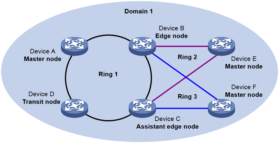
As shown in Figure 12, Ring 1 is the primary ring, and Ring 2 and Ring 3 are subrings. When the two SRPTs between the edge node and the assistant edge node are down, the master nodes of Ring 2 and Ring 3 will open their secondary ports. A loop is generated among Device B, Device C, Device E, and Device F, causing a broadcast storm.
To avoid generating a loop, the edge node will temporarily block the edge port. The blocked edge port is activated only when the edge node determines that no loop will be generated when the edge port is activated.
RRPP ring group
In an edge node RRPP ring group, only the activated subring with the smallest domain ID and ring ID can send Edge-Hello packets. In an assistant edge node RRPP ring group, any activated subring that has received Edge-Hello packets will forward these packets to the other activated subrings. When an edge node RRPP ring group and an assistant edge node RRPP ring group are configured, the CPU workload is reduced because of the following reasons:
· Only one subring sends Edge-Hello packets on the edge node.
· Only one subring receives Edge-Hello packets on the assistant edge node.
As shown in Figure 12, Device B is the edge node of Ring 2 and Ring 3. Device C is the assistant edge node of Ring 2 and Ring 3. Device B and Device C need to send or receive Edge-Hello packets frequently. If more subrings are configured or more domains are configured for load balancing, Device B and Device C will send or receive a large number of Edge-Hello packets.
To reduce Edge-Hello traffic, perform the following tasks:
· Assign Ring 2 and Ring 3 to an RRPP ring group configured on the edge node Device B.
· Assign Ring 2 and Ring 3 to an RRPP ring group configured on the assistant edge node Device C.
If all rings are activated, only Ring 2 on Device B sends Edge-Hello packets.
Typical RRPP networking
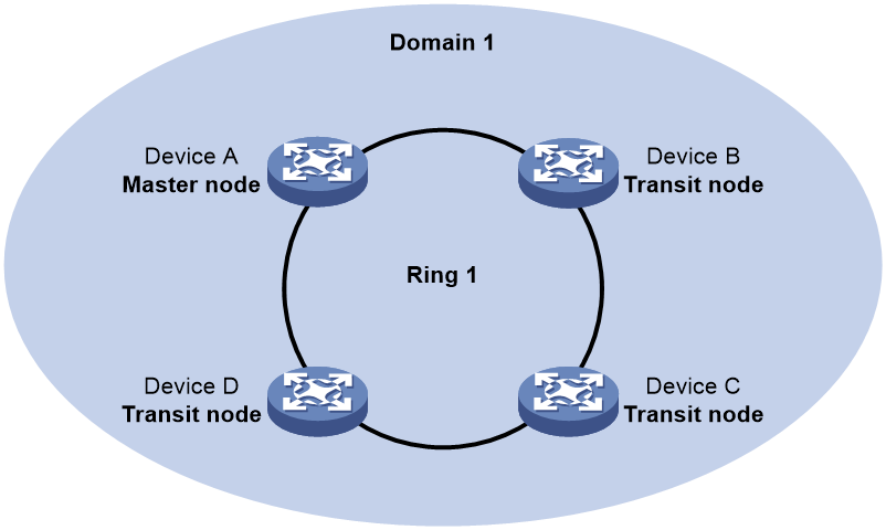
Single ring
As shown in Figure 9, only a single ring exists in the network topology. You need only define an RRPP domain.
Figure 9 Schematic diagram for a single-ring network
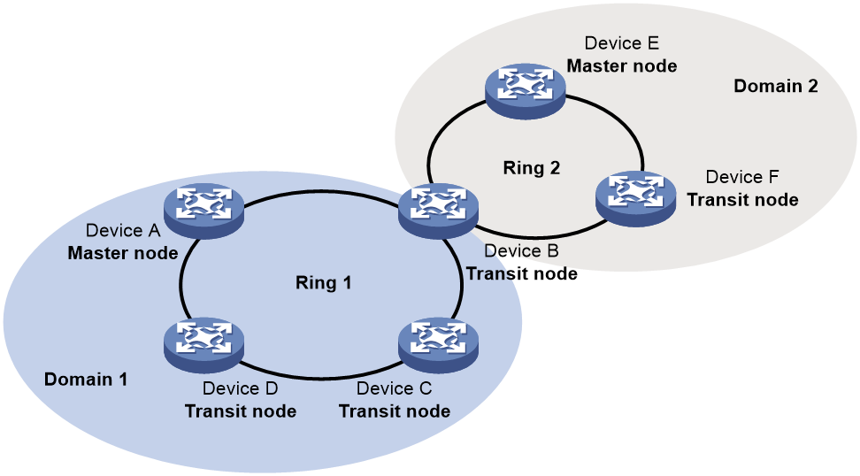
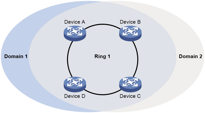
Tangent rings
As shown in Figure 10, two or more rings exist in the network topology and only one common node exists between rings. You must define an RRPP domain for each ring.
Figure 10 Schematic diagram for a tangent-ring network
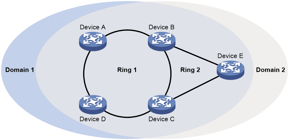
Intersecting rings
As shown in Figure 11, two or more rings exist in the network topology and two common nodes exist between rings. You need only define an RRPP domain and configure one ring as the primary ring and the other rings as subrings.
Figure 11 Schematic diagram for an intersecting-ring network
Dual-homed rings
As shown in Figure 12, two or more rings exist in the network topology and two similar common nodes exist between rings. You need only define an RRPP domain and configure one ring as the primary ring and the other rings as subrings.
Figure 12 Schematic diagram for a dual-homed-ring network
Single-ring load balancing
In a single-ring network, you can achieve load balancing by configuring multiple domains.
As shown in Figure 13:
· Ring 1 is configured as the primary ring of both Domain 1 and Domain 2.
· Domain 1 and Domain 2 are configured with different protected VLANs.
· In Domain 1, Device A is configured as the master node of Ring 1.
· In Domain 2, Device B is configured as the master node of Ring 1.
Such configurations enable the ring to block different links based on VLANs and achieve single-ring load balancing.
Figure 13 Schematic diagram for a single-ring load balancing network
Intersecting-ring load balancing
As shown in Figure 14:
· Ring 1 is the primary ring and Ring 2 is the subring in both Domain 1 and Domain 2.
· Domain 1 and Domain 2 are configured with different protected VLANs.
· Device A is configured as the master node of Ring 1 in Domain 1.
· Device D is configured as the master node of Ring 1 in Domain 2.
· Device E is configured as the master node of Ring 2 in both Domain 1 and Domain 2. However, different ports on Device E are blocked in Domain 1 and Domain 2.
Traffic from different VLANs can travel over different paths in the subring and primary ring.
Figure 14 Schematic diagram for an intersecting-ring load balancing network
Protocols and standards
RFC 3619, Extreme Networks' Ethernet Automatic Protection Switching (EAPS) Version 1
RRPP configuration task list
You can configure RRPP in the following order:
· Create RRPP domains based on service planning.
· Specify control VLANs and protected VLANs for each RRPP domain.
· Determine the ring roles and node roles based on the traffic paths in each RRPP domain.
RRPP does not have an auto election mechanism. You must configure each node in the ring network correctly for RRPP to monitor and protect the ring network.
Before you configure RRPP, you must physically construct a ring-shaped Ethernet topology.
To configure RRPP, perform the following tasks:
|
Tasks at a glance |
Remarks |
|
(Required.) Creating an RRPP domain |
Perform this task on all nodes in the RRPP domain. |
|
(Required.) Configuring control VLANs |
Perform this task on all nodes in the RRPP domain. |
|
(Required.) Configuring protected VLANs |
Perform this task on all nodes in the RRPP domain. |
|
(Required.) Configuring RRPP rings: |
Perform this task on all nodes in the RRPP domain. |
|
Perform this task on all nodes in the RRPP domain. |
|
|
(Required.) Activating an RRPP domain |
Perform this task on all nodes in the RRPP domain. |
|
(Optional.) Configuring RRPP timers |
Perform this task on the master node in the RRPP domain. |
|
(Optional.) Configuring an RRPP ring group |
Perform this task on the edge node and assistant edge node in the RRPP domain. |
|
(Optional.) Enabling SNMP notifications for RRPP |
N/A |
Creating an RRPP domain
When you create an RRPP domain, specify a domain ID to uniquely identify the RRPP domain. All devices in the same RRPP domain must be configured with the same domain ID.
Perform this task on devices you want to configure as nodes in the RRPP domain.
To create an RRPP domain:
|
Step |
Command |
Remarks |
|
1. Enter system view. |
system-view |
N/A |
|
2. Create an RRPP domain and enter RRPP domain view. |
rrpp domain domain-id |
By default, no RRPP domains exist. |
Configuring control VLANs
Before you configure RRPP rings in an RRPP domain, configure the same control VLANs for all nodes in the RRPP domain first. You need only configure the primary control VLAN for an RRPP domain. The system automatically configures the secondary control VLAN. It uses the primary control VLAN ID plus 1 as the secondary control VLAN ID. For the control VLAN configuration to succeed, make sure the IDs of the two control VLANs are consecutive and have not been previously assigned.
Follow these guidelines when you configure control VLANs:
· Do not configure the default VLAN of a port accessing an RRPP ring as the control VLAN, and do not enable VLAN mapping on control VLANs. If you do, RRPPDUs cannot be correctly forwarded.
· The primary and secondary control VLAN IDs must be different from the Layer 3 Ethernet subinterface IDs of the master ring and subrings.
· After you configure RRPP rings for an RRPP domain, you cannot delete or modify the primary control VLAN of the domain. You can only use the undo control-vlan command to delete a primary control VLAN.
· To transparently transmit RRPPDUs on a device not configured with RRPP, make sure only the two ports accessing the RRPP ring permit packets from the control VLANs. Otherwise, the packets from other VLANs might enter the control VLANs in transparent transmission mode and strike the RRPP ring.
Perform this task on all nodes in the RRPP domain to be configured.
To configure control VLANs:
|
Step |
Command |
Remarks |
|
1. Enter system view. |
system-view |
N/A |
|
2. Enter RRPP domain view. |
rrpp domain domain-id |
N/A |
|
3. Configure the primary control VLAN for the RRPP domain. |
control-vlan vlan-id |
By default, no control VLAN exists in an RRPP domain. |
Configuring protected VLANs
Before you configure RRPP rings in an RRPP domain, configure the same protected VLANs for all nodes in the RRPP domain. All VLANs to which the RRPP ports are assigned must be protected by the RRPP domains.
Protected VLANs are configured by referencing Multiple Spanning Tree Instances (MSTIs). The protected VLAN configuration method varies by the spanning tree mode:
· In STP, RSTP, or MSTP mode, you must manually configure the mappings between VLANs and MSTIs.
· In PVST mode, the device automatically maps each VLAN to an MSTI. When the spanning tree protocol is disabled globally, all VLANs are automatically mapped to MSTI 0.
For more information about spanning tree, see Layer 2—LAN Switching Configuration Guide.
|
|
IMPORTANT: When you configure load balancing, you must configure different protected VLANs for different RRPP domains. |
Perform this task on all nodes in the RRPP domain to be configured.
To configure protected VLANs:
|
Step |
Command |
Remarks |
|
1. Enter system view. |
system-view |
N/A |
|
2. Enter MST region view. |
stp region-configuration |
Not required if the device is operating in PVST mode. For more information about the command, see Layer 2—LAN Switching Command Reference. |
|
3. Configure the VLAN-to-instance mapping table. |
· Method 1: · Method 2: |
By default, all VLANs in an MST region are mapped to MSTI 0 (the CIST). Not required if the device is operating in PVST mode. For more information about the commands, see Layer 2—LAN Switching Command Reference. |
|
4. Activate MST region configuration. |
active region-configuration |
Not required if the device is operating in PVST mode. For more information about the command, see Layer 2—LAN Switching Command Reference. |
|
5. (Optional.) Display the currently activated configuration information of the MST region. |
display stp region-configuration |
Available in any view. The output of the command includes VLAN-to-instance mappings. For more information about the command, see Layer 2—LAN Switching Command Reference. |
|
6. Return to system view. |
quit |
Not required if the device is operating in PVST mode. |
|
7. Enter RRPP domain view. |
rrpp domain domain-id |
N/A |
|
8. Configure protected VLANs for the RRPP domain. |
protected-vlan reference-instance instance-id-list |
By default, no protected VLANs exist in an RRPP domain. |
Configuring RRPP rings
When you configure an RRPP ring, you must configure the ports connecting each node to the RRPP ring before configuring the nodes.
Configuring RRPP ports
Follow these guidelines when you configure RRPP ports:
· Do not enable the OAM remote loopback function on an RRPP port. Otherwise, temporary broadcast storms might occur.
· To accelerate topology convergence, use the link-delay command to enable link status rapid report function on an RRPP port. Use this command (or the undo link-delay command, depending on the device model) to set the physical state change suppression interval to 0 seconds. For more information about the link-delay command (or the undo link-delay command), see Layer 2—LAN Switching Command Reference.
Perform this task on each node's ports intended for accessing RRPP rings.
To configure RRPP ports:
|
Step |
Command |
Remarks |
|
1. Enter system view. |
system-view |
N/A |
|
2. Enter Layer 2 Ethernet interface view or Layer 2 aggregate interface view. |
interface interface-type interface-number |
N/A |
|
3. Configure the link type of the interface as trunk. |
port link-type trunk |
By default, the link type of an interface is access. For more information about the command, see Layer 2—LAN Switching Command Reference. |
|
4. Assign the trunk port to the protected VLANs of the RRPP domain. |
port trunk permit vlan { vlan-id-list | all } |
By default, a trunk port allows only packets from VLAN 1 to pass through. RRPP ports always allow packets from the control VLANs to pass through. For more information about the command, see Layer 2—LAN Switching Command Reference. |
|
5. Disable the spanning tree feature. |
undo stp enable |
By default, the spanning tree feature is enabled. For more information about the command, see Layer 2—LAN Switching Command Reference. |
Configuring RRPP nodes
If a device carries multiple RRPP rings in an RRPP domain, it can only be an edge node or an assistant edge node on a subring.
Specifying a master node
|
Step |
Command |
Remarks |
|
1. Enter system view. |
system-view |
N/A |
|
2. Enter RRPP domain view. |
rrpp domain domain-id |
N/A |
|
3. Specify the current device as the master node of the ring, and specify the primary port and the secondary port. |
ring ring-id node-mode master [ primary-port interface-type interface-number ] [ secondary-port interface-type interface-number ] level level-value |
By default, a device is not a node of the RRPP ring. |
Specifying a transit node
|
Step |
Command |
Remarks |
|
1. Enter system view. |
system-view |
N/A |
|
2. Enter RRPP domain view. |
rrpp domain domain-id |
N/A |
|
3. Specify the current device as a transit node of the ring, and specify the primary port and the secondary port. |
ring ring-id node-mode transit [ primary-port interface-type interface-number ] [ secondary-port interface-type interface-number ] level level-value |
By default, a device is not a node of the RRPP ring. |
Specifying an edge node
When you configure an edge node, you must configure the primary ring before configuring the subrings.
To specify an edge node:
|
Step |
Command |
Remarks |
|
1. Enter system view. |
system-view |
N/A |
|
2. Enter RRPP domain view. |
rrpp domain domain-id |
N/A |
|
3. Specify the current device as a master node or transit node of the primary ring, and specify the primary port and the secondary port. |
ring ring-id node-mode { master | transit } [ primary-port interface-type interface-number ] [ secondary-port interface-type interface-number ] level level-value |
By default, a device is not a node of the RRPP ring. |
|
4. Specify the current device as the edge node of a subring, and specify the edge port. |
ring ring-id node-mode edge [ edge-port interface-type interface-number ] |
By default, a device is not a node of the RRPP ring. |
Specifying an assistant edge node
When you configure an assistant edge node, you must configure the primary ring before configuring the subrings.
To specify an assistant edge node:
|
Step |
Command |
Remarks |
|
1. Enter system view. |
system-view |
N/A |
|
2. Enter RRPP domain view. |
rrpp domain domain-id |
N/A |
|
3. Specify the current device as a master node or transit node of the primary ring, and specify the primary port and the secondary port. |
ring ring-id node-mode { master | transit } [ primary-port interface-type interface-number ] [ secondary-port interface-type interface-number ] level level-value |
By default, a device is not a node of the RRPP ring. |
|
4. Specify the current device as the assistant edge node of the subring, and specify an edge port. |
ring ring-id node-mode assistant-edge [ edge-port interface-type interface-number ] |
By default, a device is not a node of the RRPP ring. |
Activating an RRPP domain
Before you activate an RRPP domain on the current device, enable the RRPP protocol and RRPP rings for the RRPP domain on the current device.
Follow these guidelines when you activate an RRPP domain:
· Before you enable subrings on a device, you must enable the primary ring. Before you disable the primary ring on the device, you must disable all subrings. Otherwise, the system displays error prompts.
· To prevent Hello packets of subrings from being looped on the primary ring, enable the primary ring on its master node first. Then enable the subrings on their respective master nodes.
Perform this task on all nodes in the RRPP domain.
To activate an RRPP domain:
|
Step |
Command |
Remarks |
|
1. Enter system view. |
system-view |
N/A |
|
2. Enable RRPP. |
rrpp enable |
By default, RRPP is disabled. |
|
3. Enter RRPP domain view. |
rrpp domain domain-id |
N/A |
|
4. Enable the specified RRPP ring. |
ring ring-id enable |
By default, an RRPP ring is disabled. |
Configuring RRPP timers
The Fail timer must be greater than or equal to three times the Hello timer.
In a dual-homed-ring network, make sure the difference between the Fail timer values on the master node of the subring and the master node of the primary ring is greater than twice the Hello timer value on the master node of the subring. Otherwise, temporary loops might occur when the primary ring fails.
Perform this task on the master node of an RRPP domain.
To configure RRPP timers:
|
Step |
Command |
Remarks |
|
1. Enter system view. |
system-view |
N/A |
|
2. Enter RRPP domain view. |
rrpp domain domain-id |
N/A |
|
3. Set the Hello timer and Fail timer for the RRPP domain. |
timer hello-timer hello-value fail-timer fail-value |
By default, the Hello timer value is 1 second and the Fail timer value is 3 seconds. |
Configuring an RRPP ring group
To reduce Edge-Hello traffic, assign subrings with the same edge node and assistant edge node to an RRPP ring group. An RRPP ring group must be configured on both the edge node and the assistant edge node. It can only be configured on these two types of nodes.
Follow these guidelines when you configure an RRPP ring group:
· You can assign a subring to only one RRPP ring group. The RRPP ring groups configured on the edge node and the assistant edge node must contain the same subrings. Otherwise, the RRPP ring group cannot operate correctly.
· The subrings in an RRPP ring group must share the same edge node and assistant edge node. The edge node and the assistant edge node must have the same SRPTs.
· Make sure a device is either the edge node or the assistant edge node on the subrings in an RRPP ring group.
· Make sure the RRPP ring groups on the edge node and the assistant edge node have the same configurations and activation status.
· Make sure all subrings in an RRPP ring group have the same SRPTs. If the SRPTs of these subrings are different, the RRPP ring group cannot operate correctly.
Perform this task on both the edge node and the assistant edge node in an RRPP domain.
To configure an RRPP ring group:
|
Step |
Command |
Remarks |
|
1. Enter system view. |
system-view |
N/A |
|
2. Create an RRPP ring group and enter RRPP ring group view. |
rrpp ring-group ring-group-id |
By default, no RRPP ring groups exist. |
|
3. Assign the specified subrings to the RRPP ring group. |
domain domain-id ring ring-id-list |
By default, no subrings are assigned to an RRPP ring group. |
Enabling SNMP notifications for RRPP
To report critical RRPP events to an NMS, enable SNMP notifications for RRPP. For RRPP event notifications to be sent correctly, you must also configure SNMP on the device. For more information about SNMP configuration, see the network management and monitoring configuration guide for the device.
To enable SNMP notifications for RRPP:
|
Step |
Command |
Remarks |
|
1. Enter system view. |
system-view |
N/A |
|
2. Enable SNMP notifications for RRPP. |
snmp-agent trap enable rrpp [ major-fault | multi-master | ring-fail | ring-recover ] * |
By default, SNMP notifications for RRPP are disabled. |
Displaying and maintaining RRPP
Execute display commands in any view and reset commands in user view.
|
Task |
Command |
|
Display brief RRPP information. |
display rrpp brief |
|
Display RRPP group configuration information. |
display rrpp ring-group [ ring-group-id ] |
|
Display RRPPDU statistics. |
display rrpp statistics domain domain-id [ ring ring-id ] |
|
Display detailed RRPP information. |
display rrpp verbose domain domain-id [ ring ring-id ] |
|
Clear RRPPDU statistics. |
reset rrpp statistics domain domain-id [ ring ring-id ] |
RRPP configuration examples
Single ring configuration example
Network requirements
As shown in Figure 15:
· Device A, Device B, Device C, and Device D form RRPP domain 1. Specify the primary control VLAN of RRPP domain 1 as VLAN 4092. Specify the protected VLANs of RRPP domain 1 as VLANs 1 through 30.
· Device A, Device B, Device C, and Device D form primary ring 1.
· Specify Device A as the master node of primary ring 1, HundredGigE 1/0/1 as the primary port, and HundredGigE 1/0/2 as the secondary port.
· Specify Device B, Device C, and Device D as the transit nodes of primary ring 1. Specify HundredGigE 1/0/1 as the primary port and HundredGigE 1/0/2 as the secondary port on Device B, Device C, and Device D.
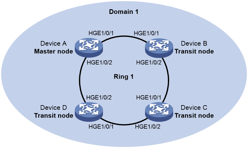
Configuration procedure
1. Configure Device A:
# Create VLANs 1 through 30.
<DeviceA> system-view
[DeviceA] vlan 1 to 30
# Map these VLANs to MSTI 1.
[DeviceA] stp region-configuration
[DeviceA-mst-region] instance 1 vlan 1 to 30
# Activate the MST region configuration.
[DeviceA-mst-region] active region-configuration
[DeviceA-mst-region] quit
# Set the physical state change suppression interval to 0 seconds on HundredGigE 1/0/1.
[DeviceA] interface hundredgige 1/0/1
[DeviceA-HundredGigE1/0/1] link-delay 0
# Disable the spanning tree feature on the port.
[DeviceA-HundredGigE1/0/1] undo stp enable
# Configure the port as a trunk port.
[DeviceA-HundredGigE1/0/1] port link-type trunk
# Assign the port to VLANs 1 through 30.
[DeviceA-HundredGigE1/0/1] port trunk permit vlan 1 to 30
[DeviceA-HundredGigE1/0/1] quit
# Configure HundredGigE 1/0/2 in the same way HundredGigE 1/0/1 is configured.
[DeviceA] interface hundredgige 1/0/2
[DeviceA-HundredGigE1/0/2] link-delay 0
[DeviceA-HundredGigE1/0/2] undo stp enable
[DeviceA-HundredGigE1/0/2] port link-type trunk
[DeviceA-HundredGigE1/0/2] port trunk permit vlan 1 to 30
[DeviceA-HundredGigE1/0/2] quit
# Create RRPP domain 1.
[DeviceA] rrpp domain 1
# Configure VLAN 4092 as the primary control VLAN of RRPP domain 1.
[DeviceA-rrpp-domain1] control-vlan 4092
# Configure the VLANs mapped to MSTI 1 as the protected VLANs of RRPP domain 1.
[DeviceA-rrpp-domain1] protected-vlan reference-instance 1
# Configure Device A as the master node of primary ring 1, with HundredGigE 1/0/1 as the primary port and HundredGigE 1/0/2 as the secondary port. Enable ring 1.
[DeviceA-rrpp-domain1] ring 1 node-mode master primary-port hundredgige 1/0/1 secondary-port hundredgige 1/0/2 level 0
[DeviceA-rrpp-domain1] ring 1 enable
[DeviceA-rrpp-domain1] quit
# Enable RRPP.
[DeviceA] rrpp enable
2. Configure Device B:
# Create VLANs 1 through 30.
<DeviceB> system-view
[DeviceB] vlan 1 to 30
# Map these VLANs to MSTI 1.
[DeviceB] stp region-configuration
[DeviceB-mst-region] instance 1 vlan 1 to 30
# Activate the MST region configuration.
[DeviceB-mst-region] active region-configuration
[DeviceB-mst-region] quit
# Set the physical state change suppression interval to 0 seconds on HundredGigE 1/0/1.
[DeviceB] interface hundredgige 1/0/1
[DeviceB-HundredGigE1/0/1] link-delay 0
# Disable the spanning tree feature on the port.
[DeviceB-HundredGigE1/0/1] undo stp enable
# Configure the port as a trunk port.
[DeviceB-HundredGigE1/0/1] port link-type trunk
# Assign the port to VLANs 1 through 30.
[DeviceB-HundredGigE1/0/1] port trunk permit vlan 1 to 30
[DeviceB-HundredGigE1/0/1] quit
# Configure HundredGigE 1/0/2 in the same way HundredGigE 1/0/1 is configured.
[DeviceB] interface hundredgige 1/0/2
[DeviceB-HundredGigE1/0/2] link-delay 0
[DeviceB-HundredGigE1/0/2] undo stp enable
[DeviceB-HundredGigE1/0/2] port link-type trunk
[DeviceB-HundredGigE1/0/2] port trunk permit vlan 1 to 30
[DeviceB-HundredGigE1/0/2] quit
# Create RRPP domain 1.
[DeviceB] rrpp domain 1
# Configure VLAN 4092 as the primary control VLAN of RRPP domain 1.
[DeviceB-rrpp-domain1] control-vlan 4092
# Configure the VLANs mapped to MSTI 1 as the protected VLANs of RRPP domain 1.
[DeviceB-rrpp-domain1] protected-vlan reference-instance 1
# Configure Device B as the transit node of primary ring 1, with HundredGigE 1/0/1 as the primary port and HundredGigE 1/0/2 as the secondary port. Enable ring 1.
[DeviceB-rrpp-domain1] ring 1 node-mode transit primary-port hundredgige 1/0/1 secondary-port hundredgige 1/0/2 level 0
[DeviceB-rrpp-domain1] ring 1 enable
[DeviceB-rrpp-domain1] quit
# Enable RRPP.
[DeviceB] rrpp enable
3. Configure Device C:
Configure Device C in the same way Device B is configured.
4. Configure Device D:
Configure Device D in the same way Device B is configured.
Verifying the configuration
# Use the display commands to view RRPP configuration and operational information on each device.
Intersecting ring configuration example
Network requirements
As shown in Figure 16:
· Device A, Device B, Device C, Device D, and Device E form RRPP domain 1. VLAN 4092 is the primary control VLAN of RRPP domain 1. RRPP domain 1 protects VLANs 1 through 30.
· Device A, Device B, Device C, and Device D form primary ring 1. Device B, Device C, and Device E form subring 2.
· Device A is the master node of primary ring 1, with HundredGigE 1/0/1 as the primary port and HundredGigE 1/0/2 the secondary port.
· Device E is the master node of subring 2, with HundredGigE 1/0/1 as the primary port and HundredGigE 1/0/2 the secondary port.
· Device B is the transit node of primary ring 1 and the edge node of subring 2, with HundredGigE 1/0/3 as the edge port.
· Device C is the transit node of primary ring 1 and the assistant edge node of subring 1, with HundredGigE 1/0/3 as the edge port.
· Device D is the transit node of primary ring 1, with HundredGigE 1/0/1 as the primary port and HundredGigE 1/0/2 the secondary port.
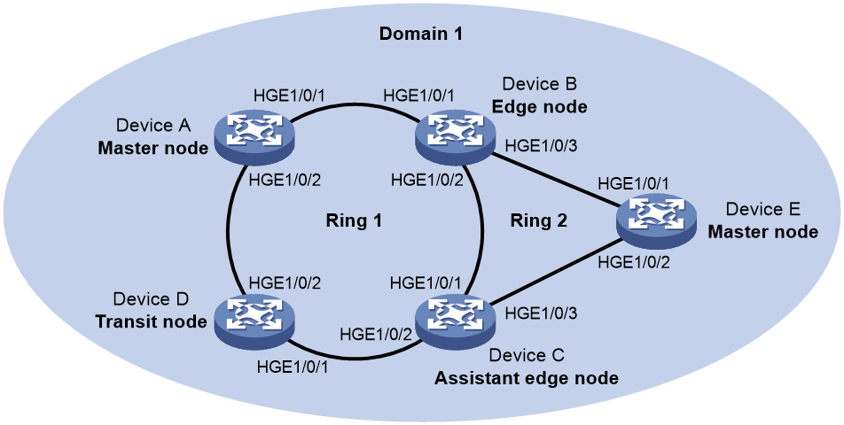
Configuration procedure
1. Configure Device A:
# Create VLANs 1 through 30.
<DeviceA> system-view
[DeviceA] vlan 1 to 30
# Map these VLANs to MSTI 1.
[DeviceA] stp region-configuration
[DeviceA-mst-region] instance 1 vlan 1 to 30
# Activate the MST region configuration.
[DeviceA-mst-region] active region-configuration
[DeviceA-mst-region] quit
# Set the physical state change suppression interval to 0 seconds on HundredGigE 1/0/1.
[DeviceA] interface hundredgige 1/0/1
[DeviceA-HundredGigE1/0/1] link-delay 0
# Disable the spanning tree feature on the port.
[DeviceA-HundredGigE1/0/1] undo stp enable
# Configure the port as a trunk port.
[DeviceA-HundredGigE1/0/1] port link-type trunk
# Assign the port to VLANs 1 through 30.
[DeviceA-HundredGigE1/0/1] port trunk permit vlan 1 to 30
[DeviceA-HundredGigE1/0/1] quit
# Configure HundredGigE 1/0/2 in the same way HundredGigE 1/0/1 is configured.
[DeviceA] interface hundredgige 1/0/2
[DeviceA-HundredGigE1/0/2] link-delay 0
[DeviceA-HundredGigE1/0/2] undo stp enable
[DeviceA-HundredGigE1/0/2] port link-type trunk
[DeviceA-HundredGigE1/0/2] port trunk permit vlan 1 to 30
[DeviceA-HundredGigE1/0/2] quit
# Create RRPP domain 1.
[DeviceA] rrpp domain 1
# Configure VLAN 4092 as the primary control VLAN of RRPP domain 1.
[DeviceA-rrpp-domain1] control-vlan 4092
# Configure the VLANs mapped to MSTI 1 as the protected VLANs of RRPP domain 1.
[DeviceA-rrpp-domain1] protected-vlan reference-instance 1
# Configure Device A as the master node of primary ring 1, with HundredGigE 1/0/1 as the primary port and HundredGigE 1/0/2 as the secondary port. Enable ring 1.
[DeviceA-rrpp-domain1] ring 1 node-mode master primary-port hundredgige 1/0/1 secondary-port hundredgige 1/0/2 level 0
[DeviceA-rrpp-domain1] ring 1 enable
[DeviceA-rrpp-domain1] quit
# Enable RRPP.
[DeviceA] rrpp enable
2. Configure Device B:
# Create VLANs 1 through 30.
<DeviceB> system-view
[DeviceB] vlan 1 to 30
# Map these VLANs to MSTI 1.
[DeviceB] stp region-configuration
[DeviceB-mst-region] instance 1 vlan 1 to 30
# Activate the MST region configuration.
[DeviceB-mst-region] active region-configuration
[DeviceB-mst-region] quit
# Set the physical state change suppression interval to 0 seconds on HundredGigE 1/0/1.
[DeviceB] interface hundredgige 1/0/1
[DeviceB-HundredGigE1/0/1] link-delay 0
# Disable the spanning tree feature on the port.
[DeviceB-HundredGigE1/0/1] undo stp enable
# Configure the port as a trunk port.
[DeviceB-HundredGigE1/0/1] port link-type trunk
# Assign the port to VLANs 1 through 30.
[DeviceB-HundredGigE1/0/1] port trunk permit vlan 1 to 30
[DeviceB-HundredGigE1/0/1] quit
# Configure HundredGigE 1/0/2 in the same way HundredGigE 1/0/1 is configured.
[DeviceB] interface hundredgige 1/0/2
[DeviceB-HundredGigE1/0/2] link-delay 0
[DeviceB-HundredGigE1/0/2] undo stp enable
[DeviceB-HundredGigE1/0/2] port link-type trunk
[DeviceB-HundredGigE1/0/2] port trunk permit vlan 1 to 30
[DeviceB-HundredGigE1/0/2] quit
# Configure HundredGigE 1/0/3 in the same way HundredGigE 1/0/1 is configured.
[DeviceB] interface hundredgige 1/0/3
[DeviceB-HundredGigE1/0/3] link-delay 0
[DeviceB-HundredGigE1/0/3] undo stp enable
[DeviceB-HundredGigE1/0/3] port link-type trunk
[DeviceB-HundredGigE1/0/3] port trunk permit vlan 1 to 30
[DeviceB-HundredGigE1/0/3] quit
# Create RRPP domain 1.
[DeviceB] rrpp domain 1
# Configure VLAN 4092 as the primary control VLAN of RRPP domain 1.
[DeviceB-rrpp-domain1] control-vlan 4092
# Configure the VLANs mapped to MSTI 1 as the protected VLANs of RRPP domain 1.
[DeviceB-rrpp-domain1] protected-vlan reference-instance 1
# Configure Device B as a transit node of primary ring 1, with HundredGigE 1/0/1 as the primary port and HundredGigE 1/0/2 as the secondary port. Enable ring 1.
[DeviceB-rrpp-domain1] ring 1 node-mode transit primary-port hundredgige 1/0/1 secondary-port hundredgige 1/0/2 level 0
[DeviceB-rrpp-domain1] ring 1 enable
# Configure Device B as the edge node of subring 2, with HundredGigE 1/0/3 as the edge port. Enable ring 2.
[DeviceB-rrpp-domain1] ring 2 node-mode edge edge-port hundredgige 1/0/3
[DeviceB-rrpp-domain1] ring 2 enable
[DeviceB-rrpp-domain1] quit
# Enable RRPP.
[DeviceB] rrpp enable
3. Configure Device C:
# Create VLANs 1 through 30.
<DeviceC> system-view
[DeviceC] vlan 1 to 30
# Map these VLANs to MSTI 1.
[DeviceC] stp region-configuration
[DeviceC-mst-region] instance 1 vlan 1 to 30
# Activate the MST region configuration.
[DeviceC-mst-region] active region-configuration
[DeviceC-mst-region] quit
# Set the physical state change suppression interval to 0 seconds on HundredGigE 1/0/1.
[DeviceC] interface hundredgige 1/0/1
[DeviceC-HundredGigE1/0/1] link-delay 0
# Disable the spanning tree feature on the port.
[DeviceC-HundredGigE1/0/1] undo stp enable
# Configure the port as a trunk port.
[DeviceC-HundredGigE1/0/1] port link-type trunk
# Assign the port to VLANs 1 through 30.
[DeviceC-HundredGigE1/0/1] port trunk permit vlan 1 to 30
[DeviceC-HundredGigE1/0/1] quit
# Configure HundredGigE 1/0/2 in the same way HundredGigE 1/0/1 is configured.
[DeviceC] interface hundredgige 1/0/2
[DeviceC-HundredGigE1/0/2] link-delay 0
[DeviceC-HundredGigE1/0/2] undo stp enable
[DeviceC-HundredGigE1/0/2] port link-type trunk
[DeviceC-HundredGigE1/0/2] port trunk permit vlan 1 to 30
[DeviceC-HundredGigE1/0/2] quit
# Configure HundredGigE 1/0/3 in the same way HundredGigE 1/0/1 is configured.
[DeviceC] interface hundredgige 1/0/3
[DeviceC-HundredGigE1/0/3] link-delay 0
[DeviceC-HundredGigE1/0/3] undo stp enable
[DeviceC-HundredGigE1/0/3] port link-type trunk
[DeviceC-HundredGigE1/0/3] port trunk permit vlan 1 to 30
[DeviceC-HundredGigE1/0/3] quit
# Create RRPP domain 1.
[DeviceC] rrpp domain 1
# Configure VLAN 4092 as the primary control VLAN of RRPP domain 1.
[DeviceC-rrpp-domain1] control-vlan 4092
# Configure the VLANs mapped to MSTI 1 as the protected VLANs of RRPP domain 1.
[DeviceC-rrpp-domain1] protected-vlan reference-instance 1
# Configure Device C as a transit node of primary ring 1, with HundredGigE 1/0/1 as the primary port and HundredGigE 1/0/2 as the secondary port. Enable ring 1.
[DeviceC-rrpp-domain1] ring 1 node-mode transit primary-port hundredgige 1/0/1 secondary-port hundredgige 1/0/2 level 0
[DeviceC-rrpp-domain1] ring 1 enable
# Configure Device C as the assistant edge node of subring 2, with HundredGigE 1/0/3 as the edge port. Enable ring 2.
[DeviceC-rrpp-domain1] ring 2 node-mode assistant-edge edge-port hundredgige 1/0/3
[DeviceC-rrpp-domain1] ring 2 enable
[DeviceC-rrpp-domain1] quit
# Enable RRPP.
[DeviceC] rrpp enable
4. Configure Device D:
# Create VLANs 1 through 30.
<DeviceD> system-view
[DeviceD] vlan 1 to 30
# Map these VLANs to MSTI 1.
[DeviceD] stp region-configuration
[DeviceD-mst-region] instance 1 vlan 1 to 30
# Activate the MST region configuration.
[DeviceD-mst-region] active region-configuration
[DeviceD-mst-region] quit
# Set the physical state change suppression interval to 0 seconds on HundredGigE 1/0/1.
[DeviceD] interface hundredgige 1/0/1
[DeviceD-HundredGigE1/0/1] link-delay 0
# Disable the spanning tree feature on the port.
[DeviceD-HundredGigE1/0/1] undo stp enable
# Configure the port as a trunk port.
[DeviceD-HundredGigE1/0/1] port link-type trunk
# Assign the port to VLANs 1 through 30.
[DeviceD-HundredGigE1/0/1] port trunk permit vlan 1 to 30
[DeviceD-HundredGigE1/0/1] quit
# Configure HundredGigE 1/0/2 in the same way HundredGigE 1/0/1 is configured.
[DeviceD] interface hundredgige 1/0/2
[DeviceD-HundredGigE1/0/2] link-delay 0
[DeviceD-HundredGigE1/0/2] undo stp enable
[DeviceD-HundredGigE1/0/2] port link-type trunk
[DeviceD-HundredGigE1/0/2] port trunk permit vlan 1 to 30
[DeviceD-HundredGigE1/0/2] quit
# Create RRPP domain 1.
[DeviceD] rrpp domain 1
# Configure VLAN 4092 as the primary control VLAN of RRPP domain 1.
[DeviceD-rrpp-domain1] control-vlan 4092
# Configure the VLANs mapped to MSTI 1 as the protected VLANs of RRPP domain 1.
[DeviceD-rrpp-domain1] protected-vlan reference-instance 1
# Configure Device D as the transit node of primary ring 1, with HundredGigE 1/0/1 as the primary port and HundredGigE 1/0/2 as the secondary port. Enable ring 1.
[DeviceD-rrpp-domain1] ring 1 node-mode transit primary-port hundredgige 1/0/1 secondary-port hundredgige 1/0/2 level 0
[DeviceD-rrpp-domain1] ring 1 enable
[DeviceD-rrpp-domain1] quit
# Enable RRPP.
[DeviceD] rrpp enable
5. Configure Device E:
# Create VLANs 1 through 30.
<DeviceE> system-view
[DeviceE] vlan 1 to 30
# Map these VLANs to MSTI 1.
[DeviceE] stp region-configuration
[DeviceE-mst-region] instance 1 vlan 1 to 30
# Activate the MST region configuration.
[DeviceE-mst-region] active region-configuration
[DeviceE-mst-region] quit
# Set the physical state change suppression interval to 0 seconds on HundredGigE 1/0/1.
[DeviceE] interface hundredgige 1/0/1
[DeviceE-HundredGigE1/0/1] link-delay 0
# Disable the spanning tree feature on the port.
[DeviceE-HundredGigE1/0/1] undo stp enable
# Configure the port as a trunk port.
[DeviceE-HundredGigE1/0/1] port link-type trunk
# Assign the port to VLANs 1 through 30.
[DeviceE-HundredGigE1/0/1] port trunk permit vlan 1 to 30
[DeviceE-HundredGigE1/0/1] quit
# Configure HundredGigE 1/0/2 in the same way HundredGigE 1/0/1 is configured.
[DeviceE] interface hundredgige 1/0/2
[DeviceE-HundredGigE1/0/2] link-delay 0
[DeviceE-HundredGigE1/0/2] undo stp enable
[DeviceE-HundredGigE1/0/2] port link-type trunk
[DeviceE-HundredGigE1/0/2] port trunk permit vlan 1 to 30
[DeviceE-HundredGigE1/0/2] quit
# Create RRPP domain 1.
[DeviceE] rrpp domain 1
# Configure VLAN 4092 as the primary control VLAN of RRPP domain 1.
[DeviceE-rrpp-domain1] control-vlan 4092
# Configure the VLANs mapped to MSTI 1 as the protected VLANs of RRPP domain 1.
[DeviceE-rrpp-domain1] protected-vlan reference-instance 1
# Configure Device E as the master node of subring 2, with HundredGigE 1/0/1 as the primary port and HundredGigE 1/0/2 as the secondary port. Enable ring 2.
[DeviceE-rrpp-domain1] ring 2 node-mode master primary-port hundredgige 1/0/1 secondary-port hundredgige 1/0/2 level 1
[DeviceE-rrpp-domain1] ring 2 enable
[DeviceE-rrpp-domain1] quit
# Enable RRPP.
[DeviceE] rrpp enable
Verifying the configuration
# Use the display commands to view RRPP configuration and operational information on each device.
Load-balanced intersecting-ring configuration example
Network requirements
As shown in Figure 17:
· Device A, Device B, Device C, Device D, and Device F form RRPP domain 1. VLAN 100 is the primary control VLAN of the RRPP domain. Device A is the master node of the primary ring, Ring 1. Device D is the transit node of Ring 1. Device F is the master node of the subring Ring 3. Device C is the edge node of the subring Ring 3. Device B is the assistant edge node of the subring Ring 3.
· Device A, Device B, Device C, Device D, and Device E form RRPP domain 2. VLAN 105 is the primary control VLAN of the RRPP domain. Device A is the master node of the primary ring, Ring 1. Device D is the transit node of Ring 1. Device E is the master node of the subring Ring 2. Device C is the edge node of the subring Ring 2. Device B is the assistant edge node of the subring Ring 2.
· Specify VLAN 11 as the protected VLAN of domain 1, and VLAN 12 the protected VLAN of domain 2. You can implement VLAN-based load balancing on Ring 1.
· Ring 2 and Ring 3 have the same edge node and assistant edge node, and the two subrings have the same SRPTs. You can add Ring 2 and Ring 3 to an RRPP ring group to reduce Edge-Hello traffic.
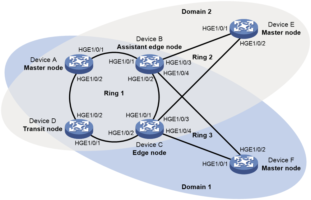
Configuration procedure
1. Configure Device A:
# Create VLANs 11 and 12.
<DeviceA> system-view
[DeviceA] vlan 11 to 12
# Map VLAN 11 to MSTI 1 and VLAN 12 to MSTI 2.
[DeviceA] stp region-configuration
[DeviceA-mst-region] instance 1 vlan 11
[DeviceA-mst-region] instance 2 vlan 12
# Activate the MST region configuration.
[DeviceA-mst-region] active region-configuration
[DeviceA-mst-region] quit
# Set the physical state change suppression interval to 0 seconds on HundredGigE 1/0/1.
[DeviceA] interface hundredgige 1/0/1
[DeviceA-HundredGigE1/0/1] link-delay 0
# Disable the spanning tree feature on the port.
[DeviceA-HundredGigE1/0/1] undo stp enable
# Configure the port as a trunk port.
[DeviceA-HundredGigE1/0/1] port link-type trunk
# Remove the port from VLAN 1, and assign it to VLANs 11 and 12.
[DeviceA-HundredGigE1/0/1] undo port trunk permit vlan 1
[DeviceA-HundredGigE1/0/1] port trunk permit vlan 11 12
# Configure VLAN 11 as the default VLAN.
[DeviceA-HundredGigE1/0/1] port trunk pvid vlan 11
[DeviceA-HundredGigE1/0/1] quit
# Configure HundredGigE 1/0/2 in the same way HundredGigE 1/0/1 is configured.
[DeviceA] interface hundredgige 1/0/2
[DeviceA-HundredGigE1/0/2] link-delay 0
[DeviceA-HundredGigE1/0/2] undo stp enable
[DeviceA-HundredGigE1/0/2] port link-type trunk
[DeviceA-HundredGigE1/0/2] undo port trunk permit vlan 1
[DeviceA-HundredGigE1/0/2] port trunk permit vlan 11 12
[DeviceA-HundredGigE1/0/2] port trunk pvid vlan 11
[DeviceA-HundredGigE1/0/2] quit
# Create RRPP domain 1.
[DeviceA] rrpp domain 1
# Configure VLAN 100 as the primary control VLAN of RRPP domain 1.
[DeviceA-rrpp-domain1] control-vlan 100
# Configure the VLAN mapped to MSTI 1 as the protected VLAN of RRPP domain 1.
[DeviceA-rrpp-domain1] protected-vlan reference-instance 1
# Configure Device A as the master node of primary ring 1, with HundredGigE 1/0/1 as the primary port and HundredGigE 1/0/2 as the secondary port. Enable ring 1.
[DeviceA-rrpp-domain1] ring 1 node-mode master primary-port hundredgige 1/0/1 secondary-port hundredgige 1/0/2 level 0
[DeviceA-rrpp-domain1] ring 1 enable
[DeviceA-rrpp-domain1] quit
# Create RRPP domain 2.
[DeviceA] rrpp domain 2
# Configure VLAN 105 as the primary control VLAN of RRPP domain 2.
[DeviceA-rrpp-domain2] control-vlan 105
# Configure the VLAN mapped to MSTI 2 as the protected VLAN of RRPP domain 2.
[DeviceA-rrpp-domain2] protected-vlan reference-instance 2
# Configure Device A as the master node of primary ring 1, with HundredGigE 1/0/2 as the master port and HundredGigE 1/0/1 as the secondary port. Enable ring 1.
[DeviceA-rrpp-domain2] ring 1 node-mode master primary-port hundredgige 1/0/2 secondary-port hundredgige 1/0/1 level 0
[DeviceA-rrpp-domain2] ring 1 enable
[DeviceA-rrpp-domain2] quit
# Enable RRPP.
[DeviceA] rrpp enable
2. Configure Device B:
# Create VLANs 11 and 12.
<DeviceB> system-view
[DeviceB] vlan 11 to 12
# Map VLAN 11 to MSTI 1 and VLAN 12 to MSTI 2.
[DeviceB] stp region-configuration
[DeviceB-mst-region] instance 1 vlan 11
[DeviceB-mst-region] instance 2 vlan 12
# Activate the MST region configuration.
[DeviceB-mst-region] active region-configuration
[DeviceB-mst-region] quit
# Set the physical state change suppression interval to 0 seconds on HundredGigE 1/0/1.
[DeviceB] interface hundredgige 1/0/1
[DeviceB-HundredGigE1/0/1] link-delay 0
# Disable the spanning tree feature on the port.
[DeviceB-HundredGigE1/0/1] undo stp enable
# Configure the port as a trunk port.
[DeviceB-HundredGigE1/0/1] port link-type trunk
# Remove the port from VLAN 1, and assign it to VLANs 11 and 12.
[DeviceB-HundredGigE1/0/1] undo port trunk permit vlan 1
[DeviceB-HundredGigE1/0/1] port trunk permit vlan 11 12
# Configure VLAN 11 as the default VLAN.
[DeviceB-HundredGigE1/0/1] port trunk pvid vlan 11
[DeviceB-HundredGigE1/0/1] quit
# Configure HundredGigE 1/0/2 in the same way HundredGigE 1/0/1 is configured.
[DeviceB] interface hundredgige 1/0/2
[DeviceB-HundredGigE1/0/2] link-delay 0
[DeviceB-HundredGigE1/0/2] undo stp enable
[DeviceB-HundredGigE1/0/2] port link-type trunk
[DeviceB-HundredGigE1/0/2] undo port trunk permit vlan 1
[DeviceB-HundredGigE1/0/2] port trunk permit vlan 11 12
[DeviceB-HundredGigE1/0/2] port trunk pvid vlan 11
[DeviceB-HundredGigE1/0/2] quit
# Set the physical state change suppression interval to 0 seconds on HundredGigE 1/0/3.
[DeviceB] interface hundredgige 1/0/3
[DeviceB-HundredGigE1/0/3] link-delay 0
# Disable the spanning tree feature on the port.
[DeviceB-HundredGigE1/0/3] undo stp enable
# Configure the port as a trunk port.
[DeviceB-HundredGigE1/0/3] port link-type trunk
# Remove the port from VLAN 1, and assign it to VLAN 12.
[DeviceB-HundredGigE1/0/3] undo port trunk permit vlan 1
[DeviceB-HundredGigE1/0/3] port trunk permit vlan 12
# Configure VLAN 12 as the default VLAN.
[DeviceB-HundredGigE1/0/3] port trunk pvid vlan 12
[DeviceB-HundredGigE1/0/3] quit
# Set the physical state change suppression interval to 0 seconds on HundredGigE 1/0/4.
[DeviceB] interface hundredgige 1/0/4
[DeviceB-HundredGigE1/0/4] link-delay 0
# Disable the spanning tree feature on the port.
[DeviceB-HundredGigE1/0/4] undo stp enable
# Configure the port as a trunk port.
[DeviceB-HundredGigE1/0/4] port link-type trunk
# Remove the port from VLAN 1, and assign it to VLAN 11.
[DeviceB-HundredGigE1/0/4] undo port trunk permit vlan 1
[DeviceB-HundredGigE1/0/4] port trunk permit vlan 11
# Configure VLAN 11 as the default VLAN.
[DeviceB-HundredGigE1/0/4] port trunk pvid vlan 11
[DeviceB-HundredGigE1/0/4] quit
# Create RRPP domain 1.
[DeviceB] rrpp domain 1
# Configure VLAN 100 as the primary control VLAN of RRPP domain 1.
[DeviceB-rrpp-domain1] control-vlan 100
# Configure the VLAN mapped to MSTI 1 as the protected VLAN of RRPP domain 1.
[DeviceB-rrpp-domain1] protected-vlan reference-instance 1
# Configure Device B as a transit node of primary ring 1 in RRPP domain 1, with HundredGigE 1/0/1 as the primary port and HundredGigE 1/0/2 as the secondary port. Enable ring 1.
[DeviceB-rrpp-domain1] ring 1 node-mode transit primary-port hundredgige 1/0/1 secondary-port hundredgige 1/0/2 level 0
[DeviceB-rrpp-domain1] ring 1 enable
# Configure Device B as the assistant edge node of subring 3 in RRPP domain 1, with HundredGigE 1/0/4 as the edge port. Enable subring 3.
[DeviceB-rrpp-domain1] ring 3 node-mode assistant-edge edge-port hundredgige 1/0/4
[DeviceB-rrpp-domain1] ring 3 enable
[DeviceB-rrpp-domain1] quit
# Create RRPP domain 2.
[DeviceB] rrpp domain 2
# Configure VLAN 105 as the primary control VLAN of RRPP domain 2.
[DeviceB-rrpp-domain2] control-vlan 105
# Configure the VLAN mapped to MSTI 2 as the protected VLAN of RRPP domain 2.
[DeviceB-rrpp-domain2] protected-vlan reference-instance 2
# Configure Device B as the transit node of primary ring 1, with HundredGigE 1/0/1 as the primary port and HundredGigE 1/0/2 as the secondary port. Enable ring 1.
[DeviceB-rrpp-domain2] ring 1 node-mode transit primary-port hundredgige 1/0/1 secondary-port hundredgige 1/0/2 level 0
[DeviceB-rrpp-domain2] ring 1 enable
# Configure Device B as the assistant edge node of subring 2 in RRPP domain 2, with HundredGigE 1/0/3 as the edge port. Enable subring 2.
[DeviceB-rrpp-domain2] ring 2 node-mode assistant-edge edge-port hundredgige 1/0/3
[DeviceB-rrpp-domain2] ring 2 enable
[DeviceC-rrpp-domain2] quit
# Enable RRPP.
[DeviceB] rrpp enable
3. Configure Device C:
# Create VLANs 11 and 12.
<DeviceC> system-view
[DeviceC] vlan 11 to 12
# Map VLAN 11 to MSTI 1 and VLAN 12 to MSTI 2.
[DeviceC] stp region-configuration
[DeviceC-mst-region] instance 1 vlan 11
[DeviceC-mst-region] instance 2 vlan 12
# Activate the MST region configuration.
[DeviceC-mst-region] active region-configuration
[DeviceC-mst-region] quit
# Set the physical state change suppression interval to 0 seconds on HundredGigE 1/0/1.
[DeviceC] interface hundredgige 1/0/1
[DeviceC-HundredGigE1/0/1] link-delay 0
# Disable the spanning tree feature on the port.
[DeviceC-HundredGigE1/0/1] undo stp enable
# Configure the port as a trunk port.
[DeviceC-HundredGigE1/0/1] port link-type trunk
# Remove the port from VLAN 1, and assign it to VLANs 11 and 12.
[DeviceC-HundredGigE1/0/1] undo port trunk permit vlan 1
[DeviceC-HundredGigE1/0/1] port trunk permit vlan 11 12
# Configure VLAN 11 as the default VLAN.
[DeviceC-HundredGigE1/0/1] port trunk pvid vlan 11
[DeviceC-HundredGigE1/0/1] quit
# Configure HundredGigE 1/0/2 in the same way HundredGigE 1/0/1 is configured.
[DeviceC] interface hundredgige 1/0/2
[DeviceC-HundredGigE1/0/2] link-delay 0
[DeviceC-HundredGigE1/0/2] undo stp enable
[DeviceC-HundredGigE1/0/2] port link-type trunk
[DeviceC-HundredGigE1/0/2] undo port trunk permit vlan 1
[DeviceC-HundredGigE1/0/2] port trunk permit vlan 11 12
[DeviceC-HundredGigE1/0/2] port trunk pvid vlan 11
[DeviceC-HundredGigE1/0/2] quit
# Set the physical state change suppression interval to 0 seconds on HundredGigE 1/0/3.
[DeviceC] interface hundredgige 1/0/3
[DeviceC-HundredGigE1/0/3] link-delay 0
# Disable the spanning tree feature on the port.
[DeviceC-HundredGigE1/0/3] undo stp enable
# Configure the port as a trunk port.
[DeviceC-HundredGigE1/0/3] port link-type trunk
# Remove the port from VLAN 1, and assign it to VLAN 12.
[DeviceC-HundredGigE1/0/3] undo port trunk permit vlan 1
[DeviceC-HundredGigE1/0/3] port trunk permit vlan 12
# Configure VLAN 12 as the default VLAN.
[DeviceC-HundredGigE1/0/3] port trunk pvid vlan 12
[DeviceC-HundredGigE1/0/3] quit
# Set the physical state change suppression interval to 0 seconds on HundredGigE 1/0/4.
[DeviceC] interface hundredgige 1/0/4
[DeviceC-HundredGigE1/0/4] link-delay 0
# Disable the spanning tree feature on the port.
[DeviceC-HundredGigE1/0/4] undo stp enable
# Configure the port as a trunk port.
[DeviceC-HundredGigE1/0/4] port link-type trunk
# Remove the port from VLAN 1, and assign it to VLAN 11.
[DeviceC-HundredGigE1/0/4] undo port trunk permit vlan 1
[DeviceC-HundredGigE1/0/4] port trunk permit vlan 11
# Configure VLAN 11 as the default VLAN.
[DeviceC-HundredGigE1/0/4] port trunk pvid vlan 11
[DeviceC-HundredGigE1/0/4] quit
# Create RRPP domain 1.
[DeviceC] rrpp domain 1
# Configure VLAN 100 as the primary control VLAN of RRPP domain 1.
[DeviceC-rrpp-domain1] control-vlan 100
# Configure the VLAN mapped to MSTI 1 as the protected VLAN of RRPP domain 1.
[DeviceC-rrpp-domain1] protected-vlan reference-instance 1
# Configure Device C as the transit node of primary ring 1 in RRPP domain 1, with HundredGigE 1/0/1 as the primary port and HundredGigE 1/0/2 as the secondary port. Enable ring 1.
[DeviceC-rrpp-domain1] ring 1 node-mode transit primary-port hundredgige 1/0/1 secondary-port hundredgige 1/0/2 level 0
[DeviceC-rrpp-domain1] ring 1 enable
# Configure Device C as the edge node of subring 3 in RRPP domain 1, with HundredGigE 1/0/4 as the edge port. Enable subring 3.
[DeviceC-rrpp-domain1] ring 3 node-mode edge edge-port hundredgige 1/0/4
[DeviceC-rrpp-domain1] ring 3 enable
[DeviceC-rrpp-domain1] quit
# Create RRPP domain 2.
[DeviceC] rrpp domain 2
# Configure VLAN 105 as the primary control VLAN of RRPP domain 2.
[DeviceC-rrpp-domain2] control-vlan 105
# Configure the VLAN mapped to MSTI 2 as the protected VLAN of RRPP domain 2.
[DeviceC-rrpp-domain2] protected-vlan reference-instance 2
# Configure Device C as the transit node of primary ring 1 in RRPP domain 2, with HundredGigE 1/0/1 as the primary port and HundredGigE 1/0/2 as the secondary port. Enable ring 1.
[DeviceC-rrpp-domain2] ring 1 node-mode transit primary-port hundredgige 1/0/1 secondary-port hundredgige 1/0/2 level 0
[DeviceC-rrpp-domain2] ring 1 enable
# Configure Device C as the edge node of subring 2 in RRPP domain 2, with HundredGigE 1/0/3 as the edge port. Enable subring 2.
[DeviceC-rrpp-domain2] ring 2 node-mode edge edge-port hundredgige 1/0/3
[DeviceC-rrpp-domain2] ring 2 enable
[DeviceC-rrpp-domain2] quit
# Enable RRPP.
[DeviceC] rrpp enable
4. Configure Device D:
# Create VLANs 11 and 12.
<DeviceD> system-view
[DeviceD] vlan 11 to 12
# Map VLAN 11 to MSTI 1 and VLAN 12 to MSTI 2.
[DeviceD] stp region-configuration
[DeviceD-mst-region] instance 1 vlan 11
[DeviceD-mst-region] instance 2 vlan 12
# Activate the MST region configuration.
[DeviceD-mst-region] active region-configuration
[DeviceD-mst-region] quit
# Set the physical state change suppression interval to 0 seconds on HundredGigE 1/0/1.
[DeviceD] interface hundredgige 1/0/1
[DeviceD-HundredGigE1/0/1] link-delay 0
# Disable the spanning tree feature on the port.
[DeviceD-HundredGigE1/0/1] undo stp enable
# Configure the port as a trunk port.
[DeviceD-HundredGigE1/0/1] port link-type trunk
# Remove the port from VLAN 1, and assign it to VLANs 11 and 12.
[DeviceD-HundredGigE1/0/1] undo port trunk permit vlan 1
[DeviceD-HundredGigE1/0/1] port trunk permit vlan 11 12
# Configure VLAN 11 as the default VLAN.
[DeviceD-HundredGigE1/0/1] port trunk pvid vlan 11
[DeviceD-HundredGigE1/0/1] quit
# Configure HundredGigE 1/0/2 in the same way HundredGigE 1/0/1 is configured.
[DeviceD] interface hundredgige 1/0/2
[DeviceD-HundredGigE1/0/2] link-delay 0
[DeviceD-HundredGigE1/0/2] undo stp enable
[DeviceD-HundredGigE1/0/2] port link-type trunk
[DeviceD-HundredGigE1/0/2] undo port trunk permit vlan 1
[DeviceD-HundredGigE1/0/2] port trunk permit vlan 11 12
[DeviceD-HundredGigE1/0/2] port trunk pvid vlan 11
[DeviceD-HundredGigE1/0/2] quit
# Create RRPP domain 1.
[DeviceD] rrpp domain 1
# Configure VLAN 100 as the primary control VLAN of RRPP domain 1.
[DeviceD-rrpp-domain1] control-vlan 100
# Configure the VLAN mapped to MSTI 1 as the protected VLAN of RRPP domain 1.
[DeviceD-rrpp-domain1] protected-vlan reference-instance 1
# Configure Device D as the transit node of primary ring 1 in RRPP domain 1, with HundredGigE 1/0/1 as the primary port and HundredGigE 1/0/2 as the secondary port. Enable ring 1.
[DeviceD-rrpp-domain1] ring 1 node-mode transit primary-port hundredgige 1/0/1 secondary-port hundredgige 1/0/2 level 0
[DeviceD-rrpp-domain1] ring 1 enable
[DeviceD-rrpp-domain1] quit
# Create RRPP domain 2.
[DeviceD] rrpp domain 2
# Configure VLAN 105 as the primary control VLAN of RRPP domain 2.
[DeviceD-rrpp-domain2] control-vlan 105
# Configure the VLAN mapped to MSTI 2 as the protected VLAN of RRPP domain 2.
[DeviceD-rrpp-domain2] protected-vlan reference-instance 2
# Configure Device D as the transit node of primary ring 1 in RRPP domain 2, with HundredGigE 1/0/1 as the primary port and HundredGigE 1/0/2 as the secondary port. Enable ring 1.
[DeviceD-rrpp-domain2] ring 1 node-mode transit primary-port hundredgige 1/0/1 secondary-port hundredgige 1/0/2 level 0
[DeviceD-rrpp-domain2] ring 1 enable
[DeviceD-rrpp-domain2] quit
# Enable RRPP.
[DeviceD] rrpp enable
5. Configure Device E:
# Create VLAN 12.
<DeviceE> system-view
[DeviceE] vlan 12
# Map VLAN 12 to MSTI 2.
[DeviceE-vlan12] quit
[DeviceE] stp region-configuration
[DeviceE-mst-region] instance 2 vlan 12
# Activate the MST region configuration.
[DeviceE-mst-region] active region-configuration
[DeviceE-mst-region] quit
# Set the physical state change suppression interval to 0 seconds on HundredGigE 1/0/1.
[DeviceE] interface hundredgige 1/0/1
[DeviceE-HundredGigE1/0/1] link-delay 0
# Disable the spanning tree feature on the port.
[DeviceE-HundredGigE1/0/1] undo stp enable
# Configure the port as a trunk port.
[DeviceE-HundredGigE1/0/1] port link-type trunk
# Remove the port from VLAN 1, and assign it to VLAN 12.
[DeviceE-HundredGigE1/0/1] undo port trunk permit vlan 1
[DeviceE-HundredGigE1/0/1] port trunk permit vlan 12
# Configure VLAN 12 as the default VLAN.
[DeviceE-HundredGigE1/0/1] port trunk pvid vlan 12
[DeviceE-HundredGigE1/0/1] quit
# Configure HundredGigE 1/0/2 in the same way HundredGigE 1/0/1 is configured.
[DeviceE] interface hundredgige 1/0/2
[DeviceE-HundredGigE1/0/2] link-delay 0
[DeviceE-HundredGigE1/0/2] undo stp enable
[DeviceE-HundredGigE1/0/2] port link-type trunk
[DeviceE-HundredGigE1/0/2] undo port trunk permit vlan 1
[DeviceE-HundredGigE1/0/2] port trunk permit vlan 12
[DeviceE-HundredGigE1/0/2] port trunk pvid vlan 12
[DeviceE-HundredGigE1/0/2] quit
# Create RRPP domain 2.
[DeviceE] rrpp domain 2
# Configure VLAN 105 as the primary control VLAN of RRPP domain 2.
[DeviceE-rrpp-domain2] control-vlan 105
# Configure the VLAN mapped to MSTI 2 as the protected VLAN of RRPP domain 2.
[DeviceE-rrpp-domain2] protected-vlan reference-instance 2
# Configure Device E as the master mode of subring 2 in RRPP domain 2, with HundredGigE 1/0/2 as the primary port and HundredGigE 1/0/1 as the secondary port. Enable ring 2.
[DeviceE-rrpp-domain2] ring 2 node-mode master primary-port hundredgige 1/0/2 secondary-port hundredgige 1/0/1 level 1
[DeviceE-rrpp-domain2] ring 2 enable
[DeviceE-rrpp-domain2] quit
# Enable RRPP.
[DeviceE] rrpp enable
6. Configure Device F:
# Create VLAN 11.
<DeviceF> system-view
[DeviceF] vlan 11
[DeviceF-vlan11] quit
# Map VLAN 11 to MSTI 1.
[DeviceF] stp region-configuration
[DeviceF-mst-region] instance 1 vlan 11
# Activate the MST region configuration.
[DeviceF-mst-region] active region-configuration
[DeviceF-mst-region] quit
# Set the physical state change suppression interval to 0 seconds on HundredGigE 1/0/1.
[DeviceF] interface hundredgige 1/0/1
[DeviceF-HundredGigE1/0/1] link-delay 0
# Disable the spanning tree feature on the port.
[DeviceF-HundredGigE1/0/1] undo stp enable
# Configure the port as a trunk port.
[DeviceF-HundredGigE1/0/1] port link-type trunk
# Remove the port from VLAN 1, and assign it to VLAN 11.
[DeviceF-HundredGigE1/0/1] undo port trunk permit vlan 1
[DeviceF-HundredGigE1/0/1] port trunk permit vlan 11
# Configure VLAN 11 as the default VLAN.
[DeviceF-HundredGigE1/0/1] port trunk pvid vlan 11
[DeviceF-HundredGigE1/0/1] quit
# Configure HundredGigE 1/0/2 in the same way HundredGigE 1/0/1 is configured.
[DeviceF] interface hundredgige 1/0/2
[DeviceF-HundredGigE1/0/2] link-delay 0
[DeviceF-HundredGigE1/0/2] undo stp enable
[DeviceF-HundredGigE1/0/2] port link-type trunk
[DeviceF-HundredGigE1/0/2] undo port trunk permit vlan 1
[DeviceF-HundredGigE1/0/2] port trunk permit vlan 11
[DeviceF-HundredGigE1/0/2] port trunk pvid vlan 11
[DeviceF-HundredGigE1/0/2] quit
# Create RRPP domain 1.
[DeviceF] rrpp domain 1
# Configure VLAN 100 as the primary control VLAN of RRPP domain 1.
[DeviceF-rrpp-domain1] control-vlan 100
# Configure the VLAN mapped to MSTI 1 as the protected VLAN of RRPP domain 1.
[DeviceF-rrpp-domain1] protected-vlan reference-instance 1
# Configure Device F as the master node of subring 3 in RRPP domain 1, with HundredGigE 1/0/1 as the primary port and HundredGigE 1/0/2 as the secondary port. Enable subring 3.
[DeviceF-rrpp-domain1] ring 3 node-mode master primary-port hundredgige 1/0/1 secondary-port hundredgige 1/0/2 level 1
[DeviceF-rrpp-domain1] ring 3 enable
[DeviceF-rrpp-domain1] quit
# Enable RRPP.
[DeviceF] rrpp enable
7. Configure RRPP ring group settings on Device B and Device C:
# Create RRPP ring group 1 on Device B, and add subrings 2 and 3 to the RRPP ring group.
[DeviceB] rrpp ring-group 1
[DeviceB-rrpp-ring-group1] domain 2 ring 2
[DeviceB-rrpp-ring-group1] domain 1 ring 3
# Create RRPP ring group 1 on Device C, and add subrings 2 and 3 to the RRPP ring group.
[DeviceC] rrpp ring-group 1
[DeviceC-rrpp-ring-group1] domain 2 ring 2
[DeviceC-rrpp-ring-group1] domain 1 ring 3
Verifying the configuration
# Use the display commands to view RRPP configuration and operational information on each device.
Troubleshooting RRPP
Symptom
When the link state is normal, the master node cannot receive Hello packets, and it unblocks the secondary port.
Solution
To resolve the problem:
1. Use the display rrpp brief command to determine whether RRPP is enabled for all nodes. If it is not, use the rrpp enable command and the ring enable command to enable RRPP and RRPP rings for all nodes.
2. Use the display rrpp brief command to determine whether the domain ID and primary control VLAN ID are the same for all nodes. If they are not, set the same domain ID and primary control VLAN ID for the nodes.
3. Use the display rrpp verbose command to examine the link state of each port in each ring.
4. Use the debugging rrpp command on each node to determine whether a port receives or transmits Hello packets. If it does not, Hello packets are lost.
5. If the problem persists, contact H3C Support.
Configuring Smart Link
Overview
To avoid single-point failures and guarantee network reliability, downstream devices are usually dual-homed to upstream devices, as shown in Figure 18.
Figure 18 Dual uplink network diagram
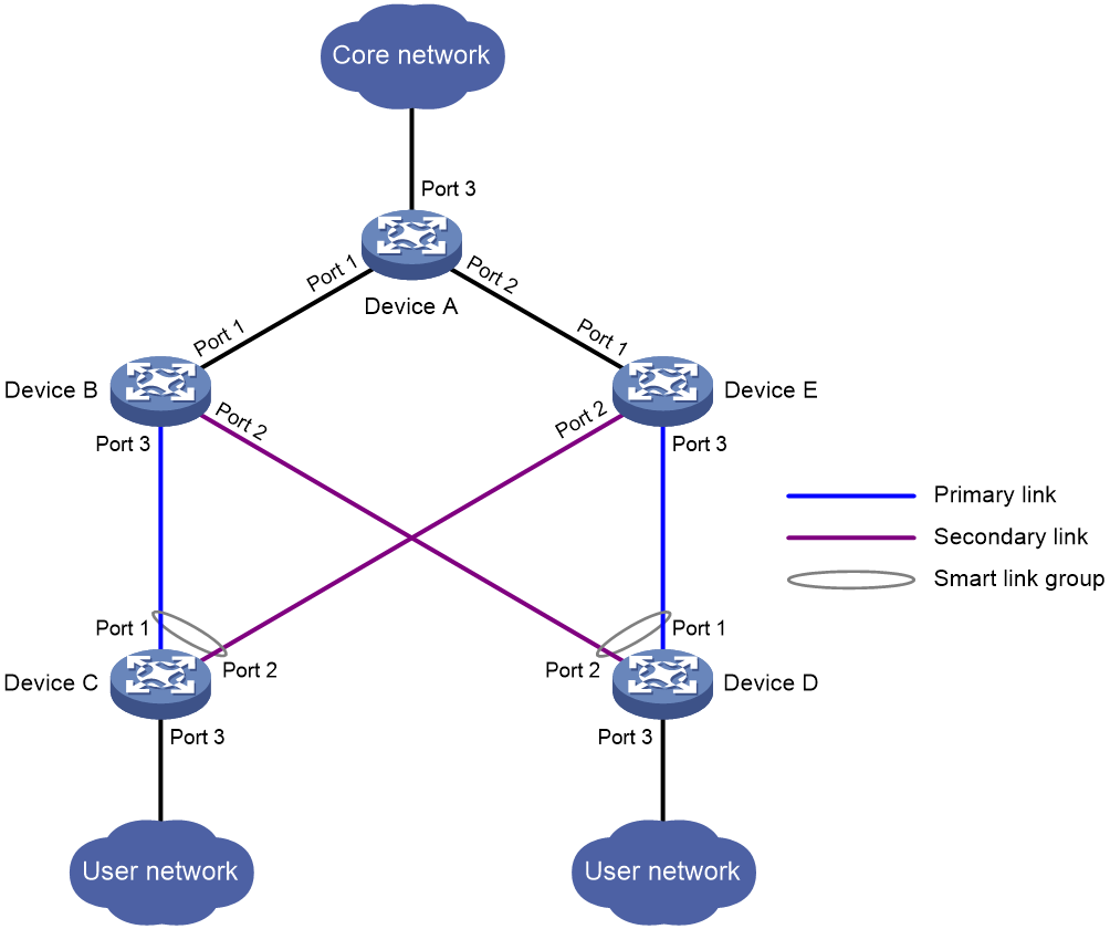
To remove network loops on a dual-homed network, you can use a spanning tree protocol or the Rapid Ring Protection Protocol (RRPP). However, convergence time is long with spanning tree protocols, which makes it unsuitable for users who have high demand on convergence speed. RRPP can meet demand on convergence speed, but it involves complicated networking and configurations and is mainly used in ring-shaped networks.
For more information about spanning tree protocols, see Layer 2—LAN Switching Configuration Guide. For more information about RRPP, see "Configuring RRPP."
Smart Link is a feature developed to address the slow convergence issue with STP. It provides link redundancy and fast convergence in a dual uplink network, allowing the backup link to take over quickly when the primary link fails. Smart Link features subsecond convergence time.
A Smart Link device is configured with a smart link group and a transmit control VLAN to transmit flush messages. For example, Device C and Device D in Figure 18 are Smart Link devices.
An associated device supports Smart Link, and receives flush messages sent from the specified control VLAN. For example, Device A, Device B, and Device E in Figure 18 are associated devices.
Terminology
Smart link group
A smart link group consists of only two member ports: the primary and the secondary ports. Only one port is active for forwarding at a time, and the other port is blocked and in standby state. When link failure occurs on the active port due to port shutdown or the presence of unidirectional link, the standby port becomes active and takes over. The original active port transits to the blocked state.
As shown in Figure 18, Port 1 and Port 2 of Device C form a smart link group and those of Device D form another. Port 1 is active and Port 2 is standby.
Primary/secondary port
Primary port and secondary port are two port types in a smart link group. When both ports in a smart link group are up, the primary port preferentially transits to the forwarding state. The secondary port stays in standby state. When the primary port fails, the secondary port takes over to forward traffic.
As shown in Figure 18, Port 1 of Device C and that of Device D are primary ports. Port 2 of Device C and that of Device D are secondary ports.
Primary/secondary link
Flush message
When link switchover occurs, the smart link group uses flush messages to notify other devices to refresh their MAC address entries and ARP/ND entries. Flush messages are common multicast data packets, and will be dropped by a blocked receiving port.
Protected VLAN
A smart link group controls the forwarding state of protected VLANs. Each smart link group on a port controls a different protected VLAN. The state of the port in a protected VLAN is determined by the state of the port in the smart link group.
Transmit control VLAN
The transmit control VLAN is used for transmitting flush messages. When link switchover occurs, the devices (such as Device C and Device D in Figure 18) send flush messages within the transmit control VLAN.
Receive control VLAN
The receive control VLAN is used for receiving and processing flush messages. When link switchover occurs, the devices (such as Device A, Device B, and Device E in Figure 18) receive and process flush messages in the receive control VLAN. In addition, they refresh their MAC address entries and ARP/ND entries.
How Smart Link works
Link backup
As shown in Figure 18, the link on Port 1 of Device C is the primary link. The link on Port 2 of Device C is the secondary link. Port 1 is in forwarding state, and Port 2 is in standby state. When the primary link fails, Port 2 takes over to forward traffic and Port 1 is blocked and placed in standby state.
When a port switches to the forwarding state, the system outputs log information to notify the user of the port state change.
Topology change
Link switchover might outdate the MAC address entries and ARP/ND entries on all devices. A flush update mechanism is provided to ensure correct packet transmission. With this mechanism, a Smart Link-enabled device updates its information by transmitting flush messages over the backup link to its upstream devices. This mechanism requires the upstream devices to be capable of recognizing Smart Link flush messages to update their MAC address forwarding entries and ARP/ND entries.
Preemption mode
As shown in Figure 18, the link on Port 1 of Device C is the primary link. The link on Port 2 of Device C is the secondary link. When the primary link fails, Port 1 is automatically blocked and placed in standby state, and Port 2 takes over to forward traffic. When the primary link recovers, one of the following actions occurs:
· If the smart link group is not configured with a preemption mode, Port 1 stays blocked to keep traffic forwarding stable. Port 1 does not take over to forward traffic until the next link switchover.
· If the smart link group is configured with a preemption mode and the preemption conditions are met, Port 1 takes over to forward traffic as soon as its link recovers. Port 2 is automatically blocked and placed in standby state.
Load sharing
A ring network might carry traffic of multiple VLANs. Smart Link can forward traffic from different VLANs in different smart link groups for load sharing.
To implement load sharing, you can assign a port to multiple smart link groups. Configure each group with a different protected VLAN. Make sure the state of the port is different in these smart link groups, so traffic from different VLANs can be forwarded along different paths.
You can configure protected VLANs for a smart link group by referencing Multiple Spanning Tree Instances (MSTIs). For more information about MSTIs, see Layer 2—LAN Switching Configuration Guide.
Collaboration between Smart Link and Monitor Link
Smart Link cannot detect when faults occur on the uplink of the upstream devices or when faults are cleared. You can configure the Monitor Link function to monitor the status of the uplink ports of the upstream devices. Monitor Link adapts the up/down state of downlink ports to uplink ports, and triggers Smart Link to perform link switchover on the downstream device. For more information about Monitor Link, see "Configuring Monitor Link."
Smart Link configuration task list
|
Tasks at a glance |
|
|
Configuring a Smart Link device: · (Required.) Configuring protected VLANs for a smart link group · (Required.) Configuring member ports for a smart link group · (Optional.) Configuring a preemption mode for a smart link group · (Optional.) Enabling the sending of flush messages |
|
|
Configuring an associated device · (Required.) Enabling the receiving of flush messages |
Configuring a Smart Link device
Configuration prerequisites
Before configuring a Smart Link device, complete the following tasks:
· To prevent loops, shut down a port before configuring it as a smart link group member. You can bring up the port only after completing the smart link group configuration.
· Disable the spanning tree feature and RRPP on the ports you want to add to the smart link group.
|
|
NOTE: · A loop might occur on the network during the time when the spanning tree feature is disabled but Smart Link has not yet taken effect on a port. · If you configure a port as both an aggregation group member and a smart link group member, only the aggregation group configuration takes effect. The port is not shown in the output from the display smart-link group command. The smart link group configuration takes effect after the port leaves the aggregation group. |
Configuring protected VLANs for a smart link group
Protected VLANs are configured by referencing MSTIs. The protected VLAN configuration method varies by the spanning tree mode:
In STP, RSTP, or MSTP mode, you must manually configure the mappings between VLANs and MSTIs.
In PVST mode, the device automatically maps each VLAN to an MSTI. When the spanning tree protocol is disabled globally, all VLANs are automatically mapped to MSTI 0.
To configure the protected VLANs for a smart link group:
|
Step |
Command |
Remarks |
|
1. Enter system view. |
system-view |
N/A |
|
2. Enter MST region view. |
stp region-configuration |
Skip this step if the device is operating in PVST mode. For more information about the command, see Layer 2—LAN Switching Command Reference. |
|
3. Configure the VLAN-to-instance mapping table. |
· Method 1: · Method 2: |
Skip this step if the device is operating in PVST mode. All VLANs in an MST region are mapped to CIST (MSTI 0) by default. For more information about the commands, see Layer 2—LAN Switching Command Reference. |
|
4. Manually activate MST region configuration. |
active region-configuration |
Skip this step if the device is operating in PVST mode. For more information about the command, see Layer 2—LAN Switching Command Reference. |
|
5. (Optional.) Display the activated MST region configuration information. |
display stp region-configuration |
Available in any view. The output of the command includes VLAN-to-instance mappings. For more information about the command, see Layer 2—LAN Switching Command Reference. |
|
6. Return to system view. |
quit |
Skip this step if the device is operating in PVST mode. |
|
7. Create a smart link group and enter smart link group view. |
smart-link group group-id |
N/A |
|
8. Configure protected VLANs for the smart link group. |
protected-vlan reference-instance instance-id-list |
By default, a smart link group does not have protected VLANs. |
Configuring member ports for a smart link group
You can configure member ports for a smart link group either in smart link group view or in interface view. The configurations made in these two views have the same effect.
In smart link group view
To configure member ports for a smart link group in smart link group view:
|
Step |
Command |
Remarks |
|
1. Enter system view. |
system-view |
N/A |
|
2. Create a smart link group and enter smart link group view. |
smart-link group group-id |
N/A |
|
3. Configure member ports for a smart link group. |
port interface-type interface-number { primary | secondary } |
By default, no member port is configured for a smart link group. |
In interface view
To configure member ports for a smart link group in interface view:
|
Step |
Command |
Remarks |
|
1. Enter system view. |
system-view |
N/A |
|
2. Enter Layer 2 Ethernet interface view or Layer 2 aggregate interface view. |
interface interface-type interface-number |
N/A |
|
3. Configure member ports for a smart link group. |
port smart-link group group-id { primary | secondary } |
By default, an interface is not a smart link group member. |
Configuring a preemption mode for a smart link group
|
Step |
Command |
Remarks |
|
1. Enter system view. |
system-view |
N/A |
|
2. Enter smart link group view. |
smart-link group group-id |
N/A |
|
3. Configure a preemption mode for the smart link group. |
preemption mode { role | speed [ threshold threshold-value ] } |
By default, preemption is disabled. |
|
4. Configure the preemption delay. |
preemption delay delay |
By default, the preemption delay is 1 second. The preemption delay configuration takes effect only after a preemption mode is configured. |
Enabling the sending of flush messages
Follow these guidelines when you enable the sending of flush messages:
· The control VLAN configured for a smart link group must be different from the control VLAN configured for any other smart link group.
· Make sure the configured control VLAN already exists, and assign the smart link group member ports to the control VLAN.
· The control VLAN of a smart link group must also be one of its protected VLANs. Do not remove the control VLAN. Otherwise, flush messages cannot be sent correctly.
To enable the sending of flush messages:
|
Step |
Command |
Remarks |
|
1. Enter system view. |
system-view |
N/A |
|
2. Enter smart link group view. |
smart-link group group-id |
N/A |
|
3. Enable flush update. |
flush enable [ control-vlan vlan-id ] |
By default, flush update is enabled, and VLAN 1 is the control VLAN. |
Configuring an associated device
Configuration prerequisites
Disable the spanning tree feature on the associated device's ports that connect to the member ports of the smart link group. Otherwise, the ports will discard flush messages when they are not in forwarding state if a topology change occurs.
Enabling the receiving of flush messages
You do not need to enable all ports on the associated devices to receive flush messages. Enable the feature only on all control VLANs of ports on the primary and secondary links between the Smart Link device and the destination device.
Follow these guidelines when you enable the receiving of flush messages:
· If no control VLAN is specified for processing flush messages, the device forwards the received flush messages without any processing.
· Make sure the receive control VLAN is the same as the transmit control VLAN configured on the Smart Link device. If they are not the same, the associated device will forward the received flush messages directly without any processing.
· Do not remove the control VLANs. Otherwise, flush messages cannot be sent correctly.
· Make sure the control VLANs are existing VLANs, and assign the ports capable of receiving flush messages to the control VLANs.
To enable the receiving of flush messages:
|
Step |
Command |
Remarks |
|
1. Enter system view. |
system-view |
N/A |
|
2. Enter Layer 2 Ethernet interface view or Layer 2 aggregate interface view. |
interface interface-type interface-number |
N/A |
|
3. Configure the control VLANs for receiving flush messages. |
smart-link flush enable [ control-vlan vlan-id-list ] |
By default, no control VLAN receives flush messages. |
Displaying and maintaining Smart Link
Perform display commands in any view and the reset command in user view:
|
Task |
Command |
|
Display information about the received flush messages. |
display smart-link flush |
|
Display smart link group information. |
display smart-link group { group-id | all } |
|
Clear the statistics about flush messages. |
reset smart-link statistics |
Smart Link configuration examples
Single smart link group configuration example
Network requirements
As shown in Figure 19:
· Device C and Device D are Smart Link devices. Device A, Device B, and Device E are associated devices. Traffic of VLANs 1 through 30 on Device C and Device D is dually uplinked to Device A.
· Configure Smart Link on Device C and Device D for dual uplink backup.
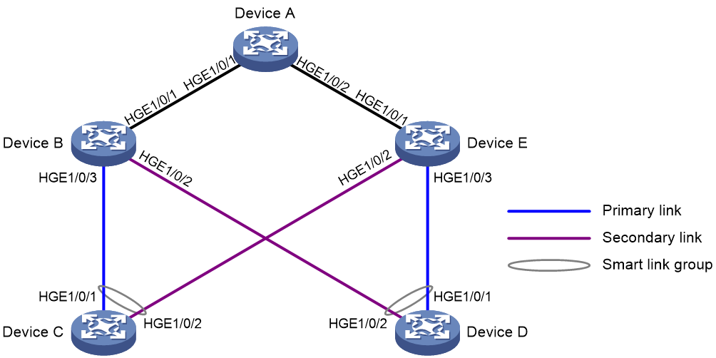
Configuration procedure
1. Configure Device C:
# Create VLANs 1 through 30.
<DeviceC> system-view
[DeviceC] vlan 1 to 30
# Map these VLANs to MSTI 1.
[DeviceC] stp region-configuration
[DeviceC-mst-region] instance 1 vlan 1 to 30
# Activate the MST region configuration.
[DeviceC-mst-region] active region-configuration
[DeviceC-mst-region] quit
# Shut down HundredGigE 1/0/1.
[DeviceC] interface hundredgige 1/0/1
[DeviceC-HundredGigE1/0/1] shutdown
# Disable the spanning tree feature on the port.
[DeviceC-HundredGigE1/0/1] undo stp enable
# Configure the port as a trunk port.
[DeviceC-HundredGigE1/0/1] port link-type trunk
# Assign the port to VLANs 1 through 30.
[DeviceC-HundredGigE1/0/1] port trunk permit vlan 1 to 30
[DeviceC-HundredGigE1/0/1] quit
# Configure HundredGigE 1/0/2 in the same way HundredGigE 1/0/1 is configured.
[DeviceC] interface hundredgige 1/0/2
[DeviceC-HundredGigE1/0/2] shutdown
[DeviceC-HundredGigE1/0/2] undo stp enable
[DeviceC-HundredGigE1/0/2] port link-type trunk
[DeviceC-HundredGigE1/0/2] port trunk permit vlan 1 to 30
[DeviceC-HundredGigE1/0/2] quit
# Create smart link group 1, and configure all VLANs mapped to MSTI 1 as the protected VLANs.
[DeviceC] smart-link group 1
[DeviceC-smlk-group1] protected-vlan reference-instance 1
# Configure HundredGigE 1/0/1 as the primary port and HundredGigE 1/0/2 as the secondary port for smart link group 1.
[DeviceC-smlk-group1] port hundredgige 1/0/1 primary
[DeviceC-smlk-group1] port hundredgige 1/0/2 secondary
# Enable flush message sending in smart link group 1, and configure VLAN 10 as the transmit control VLAN.
[DeviceC-smlk-group1] flush enable control-vlan 10
[DeviceC-smlk-group1] quit
# Bring up HundredGigE 1/0/1 and HundredGigE 1/0/2 again.
[DeviceC] interface hundredgige 1/0/1
[DeviceC-HundredGigE1/0/1] undo shutdown
[DeviceC-HundredGigE1/0/1] quit
[DeviceC] interface hundredgige 1/0/2
[DeviceC-HundredGigE1/0/2] undo shutdown
[DeviceC-HundredGigE1/0/2] quit
2. Configure Device D:
# Create VLANs 1 through 30.
<DeviceD> system-view
[DeviceD] vlan 1 to 30
# Map these VLANs to MSTI 1.
[DeviceD] stp region-configuration
[DeviceD-mst-region] instance 1 vlan 1 to 30
# Activate the MST region configuration.
[DeviceD-mst-region] active region-configuration
[DeviceD-mst-region] quit
# Shut down HundredGigE 1/0/1.
[DeviceD] interface hundredgige 1/0/1
[DeviceD-HundredGigE1/0/1] shutdown
# Disable the spanning tree feature on the port.
[DeviceD-HundredGigE1/0/1] undo stp enable
# Configure the port as a trunk port.
[DeviceD-HundredGigE1/0/1] port link-type trunk
# Assign the port to VLANs 1 through 30.
[DeviceD-HundredGigE1/0/1] port trunk permit vlan 1 to 30
[DeviceD-HundredGigE1/0/1] quit
# Configure HundredGigE 1/0/2 in the same way HundredGigE 1/0/1 is configured.
[DeviceD] interface hundredgige 1/0/2
[DeviceD-HundredGigE1/0/2] shutdown
[DeviceD-HundredGigE1/0/2] undo stp enable
[DeviceD-HundredGigE1/0/2] port link-type trunk
[DeviceD-HundredGigE1/0/2] port trunk permit vlan 1 to 30
[DeviceD-HundredGigE1/0/2] quit
# Create smart link group 1, and configure all VLANs mapped to MSTI 1 as the protected VLANs.
[DeviceD] smart-link group 1
[DeviceD-smlk-group1] protected-vlan reference-instance 1
# Configure HundredGigE 1/0/1 as the primary port and HundredGigE 1/0/2 as the secondary port for smart link group 1.
[DeviceD-smlk-group1] port hundredgige 1/0/1 primary
[DeviceD-smlk-group1] port hundredgige 1/0/2 secondary
# Enable flush message sending in smart link group 1, and configure VLAN 20 as the transmit control VLAN.
[DeviceD-smlk-group1] flush enable control-vlan 20
[DeviceD-smlk-group1] quit
# Bring up HundredGigE 1/0/1 and HundredGigE 1/0/2 again.
[DeviceD] interface hundredgige 1/0/1
[DeviceD-HundredGigE1/0/1] undo shutdown
[DeviceD-HundredGigE1/0/1] quit
[DeviceD] interface hundredgige 1/0/2
[DeviceD-HundredGigE1/0/2] undo shutdown
[DeviceD-HundredGigE1/0/2] quit
3. Configure Device B:
# Create VLANs 1 through 30.
<DeviceB> system-view
[DeviceB] vlan 1 to 30
# Configure HundredGigE 1/0/1 as a trunk port.
[DeviceB] interface hundredgige 1/0/1
[DeviceB-HundredGigE1/0/1] port link-type trunk
# Assign the port to VLANs 1 through 30.
[DeviceB-HundredGigE1/0/1] port trunk permit vlan 1 to 30
# Enable flush message receiving and configure VLAN 10 and VLAN 20 as the receive control VLANs on the port.
[DeviceB-HundredGigE1/0/1] smart-link flush enable control-vlan 10 20
[DeviceB-HundredGigE1/0/1] quit
# Configure HundredGigE 1/0/2 as a trunk port.
[DeviceB] interface hundredgige 1/0/2
[DeviceB-HundredGigE1/0/2] port link-type trunk
# Assign the port to VLANs 1 through 30.
[DeviceB-HundredGigE1/0/2] port trunk permit vlan 1 to 30
# Disable the spanning tree feature on the port.
[DeviceB-HundredGigE1/0/2] undo stp enable
# Enable flush message receiving and configure VLAN 20 as the receive control VLAN on the port.
[DeviceB-HundredGigE1/0/2] smart-link flush enable control-vlan 20
[DeviceB-HundredGigE1/0/2] quit
# Configure HundredGigE 1/0/3 as a trunk port.
[DeviceB] interface hundredgige 1/0/3
[DeviceB-HundredGigE1/0/3] port link-type trunk
# Assign the port to VLANs 1 through 30.
[DeviceB-HundredGigE1/0/3] port trunk permit vlan 1 to 30
# Disable the spanning tree feature on the port.
[DeviceB-HundredGigE1/0/3] undo stp enable
# Enable flush message receiving and configure VLAN 10 as the receive control VLAN on the port.
[DeviceB-HundredGigE1/0/3] smart-link flush enable control-vlan 10
[DeviceB-HundredGigE1/0/3] quit
4. Configure Device E:
# Create VLANs 1 through 30.
<DeviceE> system-view
[DeviceE] vlan 1 to 30
# Configure HundredGigE 1/0/1 as a trunk port.
[DeviceE] interface hundredgige 1/0/1
[DeviceE-HundredGigE1/0/1] port link-type trunk
# Assign the port to VLANs 1 through 30.
[DeviceE-HundredGigE1/0/1] port trunk permit vlan 1 to 30
# Enable flush message receiving and configure VLAN 10 and VLAN 20 as the receive control VLANs on the port.
[DeviceE-HundredGigE1/0/1] smart-link flush enable control-vlan 10 20
[DeviceE-HundredGigE1/0/1] quit
# Configure HundredGigE 1/0/2 as a trunk port.
[DeviceE] interface hundredgige 1/0/2
[DeviceE-HundredGigE1/0/2] port link-type trunk
# Assign the port to VLANs 1 through 30.
[DeviceE-HundredGigE1/0/2] port trunk permit vlan 1 to 30
# Disable the spanning tree feature on the port.
[DeviceE-HundredGigE1/0/2] undo stp enable
# Enable flush message receiving and configure VLAN 10 as the receive control VLAN on the port.
[DeviceE-HundredGigE1/0/2] smart-link flush enable control-vlan 10
[DeviceE-HundredGigE1/0/2] quit
# Configure HundredGigE 1/0/3 as a trunk port.
[DeviceE] interface hundredgige 1/0/3
[DeviceE-HundredGigE1/0/3] port link-type trunk
# Assign the port to VLANs 1 through 30.
[DeviceE-HundredGigE1/0/3] port trunk permit vlan 1 to 30
# Disable the spanning tree feature on the port.
[DeviceE-HundredGigE1/0/3] undo stp enable
# Enable flush message receiving and configure VLAN 20 as the receive control VLAN on the port.
[DeviceE-HundredGigE1/0/3] smart-link flush enable control-vlan 20
[DeviceE-HundredGigE1/0/3] quit
5. Configure Device A:
# Create VLANs 1 through 30.
<DeviceA> system-view
[DeviceA] vlan 1 to 30
# Configure HundredGigE 1/0/1 as a trunk port.
[DeviceA] interface hundredgige 1/0/1
[DeviceA-HundredGigE1/0/1] port link-type trunk
# Assign the port to VLANs 1 through 30.
[DeviceA-HundredGigE1/0/1] port trunk permit vlan 1 to 30
# Enable flush message receiving and configure VLAN 10 and VLAN 20 as the receive control VLANs on the port.
[DeviceA-HundredGigE1/0/1] smart-link flush enable control-vlan 10 20
[DeviceA-HundredGigE1/0/1] quit
# Configure HundredGigE 1/0/2 in the same way HundredGigE 1/0/1 is configured.
[DeviceA] interface hundredgige 1/0/2
[DeviceA-HundredGigE1/0/2] port link-type trunk
[DeviceA-HundredGigE1/0/2] port trunk permit vlan 1 to 30
[DeviceA-HundredGigE1/0/2] smart-link flush enable control-vlan 10 20
[DeviceA-HundredGigE1/0/2] quit
Verifying the configuration
# Display the smart link group configuration on Device C.
[DeviceC] display smart-link group 1
Smart link group 1 information:
Device ID : 000f-e23d-5af0
Preemption mode : None
Preemption delay: 1(s)
Control VLAN : 10
Protected VLAN : Reference Instance 1
Member Role State Flush-count Last-flush-time
-----------------------------------------------------------------------------
HGE1/0/1 PRIMARY ACTIVE 5 16:45:20 2012/04/21
HGE1/0/2 SECONDARY STANDBY 1 16:37:20 2012/04/21
# Display the flush messages received on Device B.
[DeviceB] display smart-link flush
Received flush packets : 5
Receiving interface of the last flush packet : HundredGigE1/0/3
Receiving time of the last flush packet : 16:50:21 2012/04/21
Device ID of the last flush packet : 000f-e23d-5af0
Control VLAN of the last flush packet : 10
Multiple smart link groups load sharing configuration example
Network requirements
As shown in Figure 20:
· Device C is a Smart Link device. Device A, Device B, and Device D are associated devices. Traffic of VLANs 1 through 200 on Device C is dually uplinked to Device A by Device B and Device D.
· Implement dual uplink backup and load sharing on Device C. Traffic of VLANs 1 through 100 is uplinked to Device A by Device B. Traffic of VLANs 101 through 200 is uplinked to Device A by Device D.
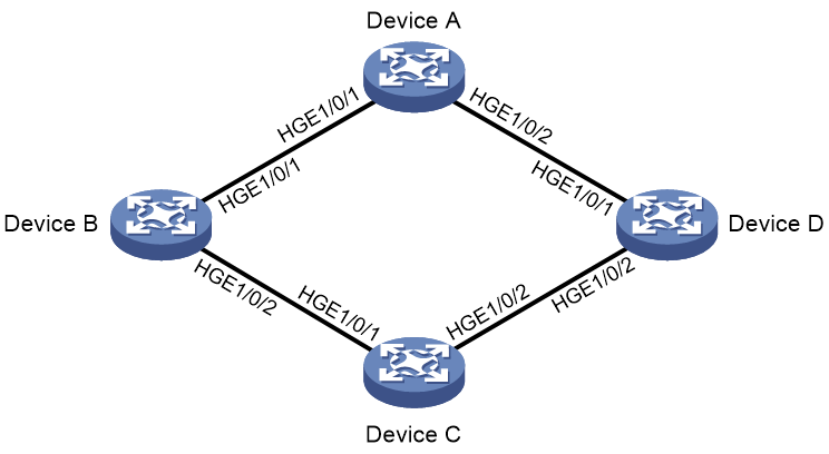
Configuration procedure
1. Configure Device C:
# Create VLAN 1 through VLAN 200.
<DeviceC> system-view
[DeviceC] vlan 1 to 200
# Map VLANs 1 through 100 to MSTI 1, and VLANs 101 through 200 to MSTI 2.
[DeviceC] stp region-configuration
[DeviceC-mst-region] instance 1 vlan 1 to 100
[DeviceC-mst-region] instance 2 vlan 101 to 200
# Activate the MST region configuration.
[DeviceC-mst-region] active region-configuration
[DeviceC-mst-region] quit
# Shut down HundredGigE 1/0/1.
[DeviceC] interface hundredgige 1/0/1
[DeviceC-HundredGigE1/0/1] shutdown
# Disable the spanning tree feature on the port.
[DeviceC-HundredGigE1/0/1] undo stp enable
# Configure the port as a trunk port.
[DeviceC-HundredGigE1/0/1] port link-type trunk
# Assign the port to VLAN 1 through VLAN 200.
[DeviceC-HundredGigE1/0/1] port trunk permit vlan 1 to 200
[DeviceC-HundredGigE1/0/1] quit
# Configure HundredGigE 1/0/2 in the same way HundredGigE 1/0/1 is configured.
[DeviceC] interface hundredgige 1/0/2
[DeviceC-HundredGigE1/0/2] shutdown
[DeviceC-HundredGigE1/0/2] undo stp enable
[DeviceC-HundredGigE1/0/2] port link-type trunk
[DeviceC-HundredGigE1/0/2] port trunk permit vlan 1 to 200
[DeviceC-HundredGigE1/0/2] quit
# Create smart link group 1, and configure all VLANs mapped to MSTI 1 as the protected VLANs for smart link group 1.
[DeviceC] smart-link group 1
[DeviceC-smlk-group1] protected-vlan reference-instance 1
# Configure HundredGigE 1/0/1 as the primary port and HundredGigE 1/0/2 as the secondary port for smart link group 1.
[DeviceC-smlk-group1] port hundredgige 1/0/1 primary
[DeviceC-smlk-group1] port hundredgige 1/0/2 secondary
# Enable role preemption in smart link group 1, enable flush message sending, and configure VLAN 10 as the transmit control VLAN.
[DeviceC-smlk-group1] preemption mode role
[DeviceC-smlk-group1] flush enable control-vlan 10
[DeviceC-smlk-group1] quit
# Create smart link group 2, and configure all VLANs mapped to MSTI 2 as the protected VLANs for smart link group 2.
[DeviceC] smart-link group 2
[DeviceC-smlk-group2] protected-vlan reference-instance 2
# Configure HundredGigE 1/0/1 as the secondary port and HundredGigE 1/0/2 as the primary port for smart link group 2.
[DeviceC-smlk-group2] port hundredgige 1/0/2 primary
[DeviceC-smlk-group2] port hundredgige 1/0/1 secondary
# Enable role preemption in smart link group 2, enable flush message sending, and configure VLAN 110 as the transmit control VLAN.
[DeviceC-smlk-group2] preemption mode role
[DeviceC-smlk-group2] flush enable control-vlan 110
[DeviceC-smlk-group2] quit
# Bring up HundredGigE 1/0/1 and HundredGigE 1/0/2.
[DeviceC] interface hundredgige 1/0/1
[DeviceC-HundredGigE1/0/1] undo shutdown
[DeviceC-HundredGigE1/0/1] quit
[DeviceC] interface hundredgige 1/0/2
[DeviceC-HundredGigE1/0/2] undo shutdown
[DeviceC-HundredGigE1/0/2] quit
2. Configure Device B:
# Create VLAN 1 through VLAN 200.
<DeviceB> system-view
[DeviceB] vlan 1 to 200
# Configure HundredGigE 1/0/1 as a trunk port.
[DeviceB] interface hundredgige 1/0/1
[DeviceB-HundredGigE1/0/1] port link-type trunk
# Assign the port to VLANs 1 through 200.
[DeviceB-HundredGigE1/0/1] port trunk permit vlan 1 to 200
# Enable flush message receiving and configure VLAN 10 and VLAN 110 as the receive control VLANs on the port.
[DeviceB-HundredGigE1/0/1] smart-link flush enable control-vlan 10 110
[DeviceB-HundredGigE1/0/1] quit
# Configure HundredGigE 1/0/2 as a trunk port.
[DeviceB] interface hundredgige 1/0/2
[DeviceB-HundredGigE1/0/2] port link-type trunk
# Assign the port to VLANs 1 through 200.
[DeviceB-HundredGigE1/0/2] port trunk permit vlan 1 to 200
# Disable the spanning tree feature on the port.
[DeviceB-HundredGigE1/0/2] undo stp enable
# Enable flush message receiving and configure VLAN 10 and VLAN 110 as the receive control VLANs on the port.
[DeviceB-HundredGigE1/0/2] smart-link flush enable control-vlan 10 110
[DeviceB-HundredGigE1/0/2] quit
3. Configure Device D:
# Create VLAN 1 through VLAN 200.
<DeviceD> system-view
[DeviceD] vlan 1 to 200
# Configure HundredGigE 1/0/1 as a trunk port.
[DeviceD] interface hundredgige 1/0/1
[DeviceD-HundredGigE1/0/1] port link-type trunk
# Assign the port to VLANs 1 through 200.
[DeviceD-HundredGigE1/0/1] port trunk permit vlan 1 to 200
# Enable flush message receiving and configure VLAN 10 and VLAN 110 as the receive control VLANs on the port.
[DeviceD-HundredGigE1/0/1] smart-link flush enable control-vlan 10 110
[DeviceD-HundredGigE1/0/1] quit
# Configure HundredGigE 1/0/2 as a trunk port.
[DeviceD] interface hundredgige 1/0/2
[DeviceD-HundredGigE1/0/2] port link-type trunk
# Assign the port to VLANs 1 through 200.
[DeviceD-HundredGigE1/0/2] port trunk permit vlan 1 to 200
# Disable the spanning tree feature on the port.
[DeviceD-HundredGigE1/0/2] undo stp enable
# Enable flush message receiving and configure VLAN 10 and VLAN 110 as the receive control VLANs on the port.
[DeviceD-HundredGigE1/0/2] smart-link flush enable control-vlan 10 110
[DeviceD-HundredGigE1/0/2] quit
4. Configure Device A:
# Create VLAN 1 through VLAN 200.
<DeviceA> system-view
[DeviceA] vlan 1 to 200
# Configure HundredGigE 1/0/1 as a trunk port.
[DeviceA] interface hundredgige 1/0/1
[DeviceA-HundredGigE1/0/1] port link-type trunk
# Assign the port to VLANs 1 through 200.
[DeviceA-HundredGigE1/0/1] port trunk permit vlan 1 to 200
# Enable flush message receiving and configure VLAN 10 and VLAN 110 as the receive control VLANs on the port.
[DeviceA-HundredGigE1/0/1] smart-link flush enable control-vlan 10 110
[DeviceA-HundredGigE1/0/1] quit
# Configure HundredGigE 1/0/2 in the same way HundredGigE 1/0/1 is configured.
[DeviceA] interface hundredgige 1/0/2
[DeviceA-HundredGigE1/0/2] port link-type trunk
[DeviceA-HundredGigE1/0/2] port trunk permit vlan 1 to 200
[DeviceA-HundredGigE1/0/2] smart-link flush enable control-vlan 10 110
[DeviceA-HundredGigE1/0/2] quit
Verifying the configuration
# Display the smart link group configuration on Device C.
[DeviceC] display smart-link group all
Smart link group 1 information:
Device ID : 000f-e23d-5af0
Preemption mode : Role
Preemption delay: 1(s)
Control VLAN : 10
Protected VLAN : Reference Instance 1
Member Role State Flush-count Last-flush-time
-----------------------------------------------------------------------------
HGE1/0/1 PRIMARY ACTIVE 5 16:45:20 2012/04/21
HGE1/0/2 SECONDARY STANDBY 1 16:37:20 2012/04/21
Smart link group 2 information:
Device ID : 000f-e23d-5af0
Preemption mode : Role
Preemption delay: 1(s)
Control VLAN : 110
Protected VLAN : Reference Instance 2
Member Role State Flush-count Last-flush-time
-----------------------------------------------------------------------------
HGE1/0/2 PRIMARY ACTIVE 5 16:45:20 2012/04/21
HGE1/0/1 SECONDARY STANDBY 1 16:37:20 2012/04/21
# Display the flush messages received on Device B.
[DeviceB] display smart-link flush
Received flush packets : 5
Receiving interface of the last flush packet : HundredGigE1/0/2
Receiving time of the last flush packet : 16:25:21 2012/04/21
Device ID of the last flush packet : 000f-e23d-5af0
Control VLAN of the last flush packet : 10
Configuring Monitor Link
Overview
Figure 21 Monitor Link application scenario
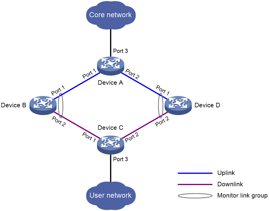
A monitor link group contains uplink and downlink interfaces. An interface can belong to only one monitor link group.
· Uplink interfaces are the monitored interfaces. The state of a monitor link group is associated with the state of its member uplink interfaces. When the number of uplink interfaces in up state in a monitor link group is less than the specified threshold, the monitor link group goes down and shuts down its downlink interfaces. When the number of uplink interfaces in up state reaches the threshold, the monitor link group comes up and brings up all its downlink interfaces.
· Downlink interfaces are the monitoring interfaces. The state of the downlink interfaces is associated with the state of the monitor link group. When the state of the monitor link group changes, the state of its member downlink interfaces changes to be consistent with the group state.
As shown in Figure 21:
· Port 1 and Port 2 of Device B form a monitor link group.
· Port 1 and Port 2 of Device D form another monitor link group.
· Port 1 is an uplink interface on both devices, and Port 2 is a downlink interface on both devices.
A monitor link group works independently of other monitor link groups. When the number of uplink interfaces in up state in a monitor link group is less than the specified threshold, the monitor link group goes down and shuts down its downlink interfaces. When the number of uplink interfaces in up state reaches the threshold, the monitor link group comes up and brings up all its downlink interfaces.
Configuration restrictions and guidelines
Follow these restrictions and guidelines when you configure Monitor Link:
· Do not manually shut down or bring up the downlink interfaces in a monitor link group.
· To avoid frequent state changes of downlink interfaces in the event that uplink interfaces in the monitor link group flap, you can configure a switchover delay. The switchover delay is the time that the downlink interfaces wait before they come up following an uplink interface.
Monitor Link configuration task list
|
Tasks at a glance |
|
(Required.) Enabling Monitor Link globally |
|
(Required.) Creating a monitor link group |
|
(Required.) Configuring monitor link group member interfaces |
|
(Optional.) Configuring the uplink interface threshold for triggering monitor link group state switchover |
|
(Optional.) Configuring the switchover delay for the downlink interfaces in a monitor link group |
Enabling Monitor Link globally
All monitor link groups can operate only after you enable Monitor Link globally. When you disable Monitor Link globally, all monitor link groups cannot operate and the downlink interfaces brought down by the monitor link groups resume their original states.
To enable Monitor Link globally:
|
Step |
Command |
Remarks |
|
1. Enter system view. |
system-view |
N/A |
|
2. Enable Monitor Link globally. |
undo monitor-link disable |
By default, Monitor Link is enabled globally. |
Creating a monitor link group
|
Step |
Command |
Remarks |
|
1. Enter system view. |
system-view |
N/A |
|
2. Create a monitor link group and enter monitor link group view. |
monitor-link group group-id |
By default, no monitor link groups exist. |
Configuring monitor link group member interfaces
You can configure member interfaces for a monitor link group in monitor link group view or interface view. Configurations made in these views have the same effect. The configuration is supported by the following interfaces:
· Layer 2 Ethernet interfaces and Layer 2 aggregate interfaces.
· Layer 3 Ethernet interfaces/subinterfaces and Layer 3 aggregate interfaces/subinterfaces.
Follow these guidelines when you configure monitor link group member interfaces:
· If you have configured an interface as the downlink interface of a monitor link group, do not configure its subinterfaces as the uplink interfaces of any monitor link group. Otherwise, the Monitor Link operation might be interrupted.
· The state of subinterfaces is associated with the state of the interface. Do not add the interface and its subinterfaces to the same monitor link group. Otherwise, the monitor link group performance might be affected.
· Do not add an aggregate interface and its member ports to the same monitor link group. Otherwise, the Monitor Link operation might be interrupted.
· An interface can be assigned to only one monitor link group.
· To avoid undesired down/up state changes on the downlink interfaces, configure uplink interfaces before you configure downlink interfaces.
In monitor link group view
To configure member interfaces for a monitor link group in monitor link group view:
|
Step |
Command |
Remarks |
|
1. Enter system view. |
system-view |
N/A |
|
2. Enter monitor link group view. |
monitor-link group group-id |
N/A |
|
3. Configure member interfaces for the monitor link group. |
port interface-type { interface-number | interface-number.subnumber } { downlink | uplink } |
By default, no member interfaces exist in a monitor link group. |
In interface view
To configure member interfaces for a monitor link group in interface view:
|
Step |
Command |
Remarks |
|
1. Enter system view. |
system-view |
N/A |
|
2. Enter interface view or subinterface view. |
interface interface-type { interface-number | interface-number.subnumber } |
N/A |
|
3. Configure the interface as a member of a monitor link group. |
port monitor-link group group-id { downlink | uplink } |
By default, the interface/subinterface is not a monitor link group member. |
Configuring the uplink interface threshold for triggering monitor link group state switchover
|
Step |
Command |
Remarks |
|
1. Enter system view. |
system-view |
N/A |
|
2. Enter monitor link group view. |
monitor-link group group-id |
N/A |
|
3. Configure the uplink interface threshold for triggering monitor link group state switchover. |
uplink up-port-threshold number-of-port |
By default, the uplink interface threshold for triggering monitor link group state switchover is 1. |
Configuring the switchover delay for the downlink interfaces in a monitor link group
|
Step |
Command |
Remarks |
|
1. Enter system view. |
system-view |
N/A |
|
2. Enter monitor link group view. |
monitor-link group group-id |
N/A |
|
3. Configure the switchover delay for the downlink interfaces in the monitor link group. |
downlink up-delay delay |
By default, the switchover delay is 0 seconds. The downlink interfaces come up as soon as an uplink interface comes up. |
Displaying and maintaining Monitor Link
Execute the display command in any view:
|
Task |
Command |
|
Display monitor link group information. |
display monitor-link group { group-id | all } |
Monitor Link configuration example
Network requirements
As shown in Figure 22:
· Device C is a Smart Link device, and Device A, Device B, and Device D are associated devices. Traffic of VLANs 1 through 30 on Device C is dual-uplinked to Device A through a smart link group.
· Implement dual uplink backup on Device C. When the link between Device A and Device B (or Device D) fails, Device C can detect the link fault. It then performs uplink switchover in the smart link group.
For more information about Smart Link, see "Configuring Smart Link."
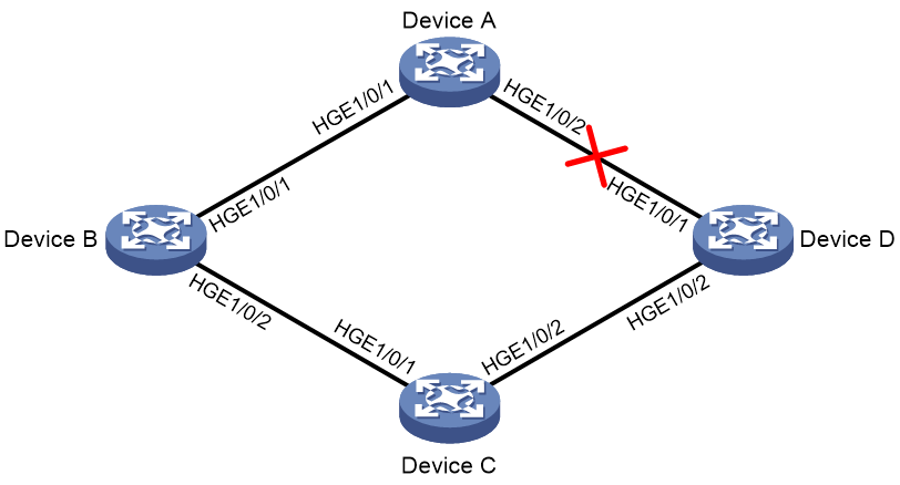
Configuration procedure
1. Configure Device C:
# Create VLANs 1 through 30.
<DeviceC> system-view
[DeviceC] vlan 1 to 30
# Map these VLANs to MSTI 1.
[DeviceC] stp region-configuration
[DeviceC-mst-region] instance 1 vlan 1 to 30
# Activate MST region configuration.
[DeviceC-mst-region] active region-configuration
[DeviceC-mst-region] quit
# Shut down HundredGigE 1/0/1.
[DeviceC] interface hundredgige 1/0/1
[DeviceC-HundredGigE1/0/1] shutdown
# Disable the spanning tree feature on the interface.
[DeviceC-HundredGigE1/0/1] undo stp enable
# Configure the interface as a trunk port.
[DeviceC-HundredGigE1/0/1] port link-type trunk
# Assign the interface to VLANs 1 through 30.
[DeviceC-HundredGigE1/0/1] port trunk permit vlan 1 to 30
[DeviceC-HundredGigE1/0/1] quit
# Configure HundredGigE 1/0/2 in the same way HundredGigE 1/0/1 is configured.
[DeviceC] interface hundredgige 1/0/2
[DeviceC-HundredGigE1/0/2] shutdown
[DeviceC-HundredGigE1/0/2] undo stp enable
[DeviceC-HundredGigE1/0/2] port link-type trunk
[DeviceC-HundredGigE1/0/2] port trunk permit vlan 1 to 30
[DeviceC-HundredGigE1/0/2] quit
# Create smart link group 1, and configure all the VLANs mapped to MSTI 1 as the protected VLANs for smart link group 1.
[DeviceC] smart-link group 1
[DeviceC-smlk-group1] protected-vlan reference-instance 1
# Configure HundredGigE 1/0/1 as the primary port and HundredGigE 1/0/2 as the secondary port for smart link group 1.
[DeviceC-smlk-group1] port hundredgige 1/0/1 primary
[DeviceC-smlk-group1] port hundredgige 1/0/2 secondary
# Enable the smart link group to transmit flush messages.
[DeviceC-smlk-group1] flush enable
[DeviceC-smlk-group1] quit
# Bring up HundredGigE 1/0/1 and HundredGigE 1/0/2.
[DeviceC] interface hundredgige 1/0/1
[DeviceC-HundredGigE1/0/1] undo shutdown
[DeviceC-HundredGigE1/0/1] quit
[DeviceC] interface hundredgige 1/0/2
[DeviceC-HundredGigE1/0/2] undo shutdown
[DeviceC-HundredGigE1/0/2] quit
2. Configure Device A:
# Create VLANs 1 through 30.
<DeviceA> system-view
[DeviceA] vlan 1 to 30
# Configure HundredGigE 1/0/1 as a trunk port.
[DeviceA] interface hundredgige 1/0/1
[DeviceA-HundredGigE1/0/1] port link-type trunk
# Assign the interface to VLANs 1 through 30.
[DeviceA-HundredGigE1/0/1] port trunk permit vlan 1 to 30
# Enable flush message receiving on the interface.
[DeviceA-HundredGigE1/0/1] smart-link flush enable
[DeviceA-HundredGigE1/0/1] quit
# Configure HundredGigE 1/0/2 in the same way HundredGigE 1/0/1 is configured.
[DeviceA] interface hundredgige 1/0/2
[DeviceA-HundredGigE1/0/2] port link-type trunk
[DeviceA-HundredGigE1/0/2] port trunk permit vlan 1 to 30
[DeviceA-HundredGigE1/0/2] smart-link flush enable
[DeviceA-HundredGigE1/0/2] quit
3. Configure Device B:
# Create VLANs 1 through 30.
<DeviceB> system-view
[DeviceB] vlan 1 to 30
# Configure HundredGigE 1/0/1 as a trunk port.
[DeviceB] interface hundredgige 1/0/1
[DeviceB-HundredGigE1/0/1] port link-type trunk
# Assign the interface to VLANs 1 through 30.
[DeviceB-HundredGigE1/0/1] port trunk permit vlan 1 to 30
# Enable flush message receiving on the interface.
[DeviceB-HundredGigE1/0/1] smart-link flush enable
[DeviceB-HundredGigE1/0/1] quit
# Disable the spanning tree feature on HundredGigE 1/0/2.
[DeviceB] interface hundredgige 1/0/2
[DeviceB-HundredGigE1/0/2] undo stp enable
# Configure the interface as a trunk port.
[DeviceB-HundredGigE1/0/2] port link-type trunk
# Assign the interface to VLANs 1 through 30.
[DeviceB-HundredGigE1/0/2] port trunk permit vlan 1 to 30
# Enable flush message receiving on the interface.
[DeviceB-HundredGigE1/0/2] smart-link flush enable
[DeviceB-HundredGigE1/0/2] quit
# Create monitor link group 1.
[DeviceB] monitor-link group 1
# Configure HundredGigE 1/0/1 as an uplink interface for monitor link group 1.
[DeviceB-mtlk-group1] port hundredgige 1/0/1 uplink
# Configure HundredGigE 1/0/2 as a downlink interface for monitor link group 1.
[DeviceB-mtlk-group1] port hundredgige 1/0/2 downlink
[DeviceB-mtlk-group1] quit
4. Configure Device D:
# Create VLANs 1 through 30.
<DeviceD> system-view
[DeviceD] vlan 1 to 30
# Configure HundredGigE 1/0/1 as a trunk port.
[DeviceD] interface hundredgige 1/0/1
[DeviceD-HundredGigE1/0/1] port link-type trunk
# Assign the interface to VLANs 1 through 30.
[DeviceD-HundredGigE1/0/1] port trunk permit vlan 1 to 30
# Enable flush message receiving on the interface.
[DeviceD-HundredGigE1/0/1] smart-link flush enable
[DeviceD-HundredGigE1/0/1] quit
# Disable the spanning tree feature on HundredGigE 1/0/2.
[DeviceD] interface hundredgige 1/0/2
[DeviceD-HundredGigE1/0/2] undo stp enable
# Configure the interface as a trunk port.
[DeviceD-HundredGigE1/0/2] port link-type trunk
# Assign the interface to VLANs 1 through 30.
[DeviceD-HundredGigE1/0/2] port trunk permit vlan 1 to 30
# Enable flush message receiving on the interface.
[DeviceD-HundredGigE1/0/2] smart-link flush enable
[DeviceD-HundredGigE1/0/2] quit
# Create monitor link group 1.
[DeviceD] monitor-link group 1
# Configure HundredGigE 1/0/1 as an uplink interface for monitor link group 1.
[DeviceD-mtlk-group1] port hundredgige 1/0/1 uplink
# Configure HundredGigE 1/0/2 as a downlink interface for monitor link group 1.
[DeviceD-mtlk-group1] port hundredgige 1/0/2 downlink
[DeviceD-mtlk-group1] quit
Verifying the configuration
# When HundredGigE 1/0/2 on Device A goes down because of a link fault, verify information about monitor link group 1 on Device B.
[DeviceB] display monitor-link group 1
Monitor link group 1 information:
Group status : UP
Downlink up-delay: 0(s)
Last-up-time : 16:38:26 2012/4/21
Last-down-time : 16:37:20 2012/4/21
Up-port-threshold: 1
Member Role Status
--------------------------------------------
HGE1/0/1 UPLINK UP
HGE1/0/2 DOWNLINK UP
# Verify information about monitor link group 1 on Device D.
[DeviceD] display monitor-link group 1
Monitor link group 1 information:
Group status : DOWN
Downlink up-delay: 0(s)
Last-up-time : 16:37:20 2012/4/21
Last-down-time : 16:38:26 2012/4/21
Up-port-threshold: 1
Member Role Status
--------------------------------------------
HGE1/0/1 UPLINK DOWN
HGE1/0/2 DOWNLINK DOWN
Configuring VRRP
Overview
Typically, you can configure a default gateway for every host on a LAN. All packets destined for other networks are sent through the default gateway. As shown in Figure 23, when the default gateway fails, no hosts can communicate with external networks.
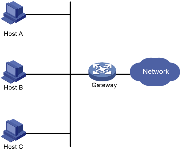
Using a default gateway facilitates your configuration but requires high availability. Using more egress gateways improves link availability but introduces the problem of routing among the egresses.
Virtual Router Redundancy Protocol (VRRP) is designed to address this issue. VRRP adds a group of network gateways to a VRRP group called a virtual router. The VRRP group has one master and multiple backups, and provides a virtual IP address. The hosts on the subnet use the virtual IP address as their default network gateway to communicate with external networks.
The virtual IP address of the virtual router can be either of the following IP addresses:
· Unused IP address on the subnet where the VRRP group resides.
· IP address of an interface on a router in the VRRP group.
In the latter case, the router is called the IP address owner. A VRRP group can have only one IP address owner.
VRRP avoids single points of failure and simplifies the configuration on hosts. When the master in the VRRP group on a multicast or broadcast LAN (for example, an Ethernet network) fails, another router in the VRRP group takes over. The switchover is complete without causing dynamic route recalculation, route re-discovery, gateway reconfiguration on the hosts, or traffic interruption.
VRRP operates in either of the following modes:
· Standard mode—Implemented based on RFCs. For more information, see "VRRP standard mode."
· Load balancing mode—Extends the VRRP standard mode to distribute load across VRRP group members. For more information, see "VRRP load balancing mode."
VRRP has two versions: VRRPv2 and VRRPv3. VRRPv2 supports IPv4 VRRP. VRRPv3 supports IPv4 VRRP and IPv6 VRRP.
VRRP group
The administrator can add a router to a VRRP group by creating the VRRP group on a Layer 3 interface on the router.
|
|
NOTE: On a device, the interfaces added to VRRP groups having the same VRRP group number belong to different VRRP groups. |
VRRP standard mode
In VRRP standard mode, only the master in the VRRP group can provide gateway service. When the master fails, the backup routers elect a new master to take over for nonstop gateway service.
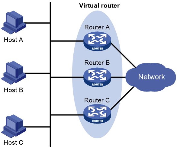
As shown in Figure 24, Router A, Router B, and Router C form a virtual router, which has its own IP address. Hosts on the subnet use the virtual router as the default gateway.
The router with the highest priority among the three routers is elected as the master, and the other two are backups.
Router priority in a VRRP group
VRRP determines the role (master or backup) of each router in a VRRP group by priority. A router with higher priority is more likely to become the master.
A VRRP priority can be in the range of 0 to 255, and a greater number represents a higher priority. Priorities 1 to 254 are configurable. Priority 0 is reserved for special uses, and priority 255 is for the IP address owner. The IP address owner in a VRRP group always has a running priority of 255 and acts as the master as long as it operates correctly.
Preemption
A router in a VRRP group operates in either non-preemptive mode or preemptive mode.
· Non-preemptive mode—The master router acts as the master as long as it operates correctly, even if a backup router is later assigned a higher priority. Non-preemptive mode helps avoid frequent switchover between the master and backup routers.
· Preemptive mode—A backup starts a new master election and takes over as master when it detects that it has a higher priority than the current master. Preemptive mode ensures that the router with the highest priority in a VRRP group always acts as the master.
Authentication method
To avoid attacks from unauthorized users, VRRP member routers add authentication keys in VRRP packets to authenticate one another. VRRP provides the following authentication methods:
· Simple authentication
The sender fills an authentication key into the VRRP packet, and the receiver compares the received authentication key with its local authentication key. If the two authentication keys match, the received VRRP packet is legitimate. Otherwise, the received packet is illegitimate and gets discarded.
· MD5 authentication
The sender computes a digest for the VRRP packet by using the authentication key and MD5 algorithm, and saves the result to the packet. The receiver performs the same operation with the authentication key and MD5 algorithm, and compares the result with the content in the authentication header. If the results match, the received VRRP packet is legitimate. Otherwise, the received packet is illegitimate and gets discarded.
On a secure network, you can choose to not authenticate VRRP packets.
|
|
NOTE: IPv4 VRRPv3 and IPv6 VRRPv3 do not support VRRP packet authentication. |
VRRP timers
Skew_Time
Skew_Time helps avoid the situation that multiple backups in a VRRP group become the master when the master in the VRRP group fails.
Skew_Time is not configurable; its value depends on the VRRP version.
· In VRRPv2 (described in RFC 3768), Skew_Time is (256 – Router priority)/256.
· In VRRPv3 (described in RFC 5798), Skew_Time is ((256 – Router priority) × VRRP advertisement interval)/256.
VRRP advertisement interval
The master in a VRRP group periodically sends VRRP advertisements to declare its presence.
You can configure the interval at which the master sends VRRP advertisements. If a backup does not receive any VRRP advertisement when the timer (3 × VRRP advertisement interval + Skew_Time) expires, it takes over as the master.
VRRP preemption delay timer
You can configure the VRRP preemption delay timer for the following purposes:
· Avoid frequent state changes among members in a VRRP group.
· Provide the backups with enough time to collect information (such as routing information).
In preempt mode, a backup does not immediately become the master after it receives an advertisement with lower priority than the local priority. Instead, it waits for a period of time (preemption delay time + Skew_Time) before taking over as the master.
Master election
Routers in a VRRP group determine their roles by priority. When a router joins a VRRP group, it has a backup role. The router role changes according to the following situations:
· If the backup does not receive any VRRP advertisement when the timer (3 × advertisement interval + Skew_Time) expires, it becomes the master.
· If the backup receives a VRRP advertisement with the same or greater priority within the timer (3 × advertisement interval + Skew_Time), it remains a backup.
· If the backup receives a VRRP advertisement with a smaller priority within the timer (3 × advertisement interval + Skew_Time), the following results apply:
¡ It remains a backup when operating in non-preemptive mode.
¡ It becomes the master when operating in preemptive mode.
The elected master starts a VRRP advertisement interval to periodically send VRRP advertisements to notify the backups that it is operating correctly. Each of the backups starts a timer to wait for advertisements from the master.
After a backup receives a VRRP advertisement, it compares only the priority in the packet with its own priority.
When multiple routers in a VRRP group declare that they are the master because of network problems, the one with the highest priority becomes the master. If two routers have the same priority, the one with the highest IP address becomes the master.
VRRP tracking
To enable VRRP tracking, configure the routers in the VRRP group to operate in preemptive mode first. This configuration ensures that only the router with the highest priority operates as the master.
The VRRP tracking function uses network quality analyzer (NQA) or bidirectional forwarding detection (BFD) to monitor the state of the master or the upstream link. The collaboration between VRRP and NQA or BFD through a track entry implements the following functions:
· Monitors the upstream link and changes the priority of the router according to the state of the link. If the upstream link fails, the hosts on the subnet cannot access external networks through the router and the state of the track entry becomes Negative. The priority of the master decreases by a specified value, and a router with a higher priority in the VRRP group becomes the master. The switchover ensures uninterrupted communication between the hosts on the subnet and external networks.
· Monitors the state of the master on the backups. When the master fails, a backup immediately takes over to ensure uninterrupted communication.
When the track entry changes from Negative to Positive or Notready, the router automatically restores its priority. For more information about track entries, see "Configuring Track."
VRRP application
Master/backup
In master/backup mode, only the master forwards packets, as shown in Figure 25. When the master fails, a new master is elected from among the backups. This mode requires only one VRRP group, and each router in the group has a different priority. The one with the highest priority becomes the master.
Figure 25 VRRP in master/backup mode
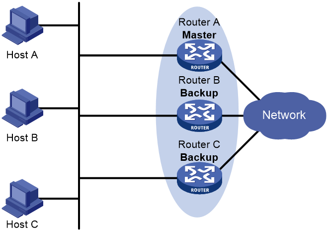
Assume that Router A is acting as the master to forward packets to external networks, and Router B and Router C are backups in listening state. When Router A fails, Router B and Router C elect a new master to forward packets for hosts on the subnet.
Load sharing
A router can join multiple VRRP groups. With different priorities in different VRRP groups, the router can act as the master in one VRRP group and a backup in another.
In load sharing mode, multiple VRRP groups provide gateway services. This mode requires a minimum of two VRRP groups, and each group has one master and multiple backups. The master roles in the VRRP groups are assumed by different routers, as shown in Figure 26.
Figure 26 Load sharing of VRRP
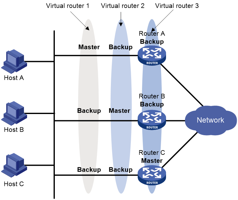
A router can be in multiple VRRP groups and have a different priority in each group.
As shown in Figure 26, the following VRRP groups exist:
· VRRP group 1—Router A is the master. Router B and Router C are the backups.
· VRRP group 2—Router B is the master. Router A and Router C are the backups.
· VRRP group 3—Router C is the master. Router A and Router B are the backups.
To implement load sharing among Router A, Router B, and Router C, perform the following tasks:
· Configure the virtual IP addresses of VRRP group 1, 2, and 3 as default gateway IP addresses for hosts on the subnet.
· Assign the highest priority to Router A, B, and C in VRRP group 1, 2, and 3, respectively.
VRRP load balancing mode
In a standard-mode VRRP group, only the master can forward packets and backups are in listening state. You can create multiple VRRP groups to share traffic, but you must configure different gateways for hosts on the subnet.
In load balancing mode, a VRRP group maps its virtual IP address to multiple virtual MAC addresses, assigning one virtual MAC address to each member router. Every router in this VRRP group can forward traffic and respond to IPv4 ARP requests or IPv6 ND requests from hosts. Because their virtual MAC addresses are different, traffic from hosts is distributed across the VRRP group members. Load balancing mode simplifies configuration and improves forwarding efficiency.
VRRP load balancing mode uses the same master election, preemption, and tracking mechanisms as the standard mode. New mechanisms have been introduced to VRRP load balancing mode, as described in the following sections.
Virtual MAC address assignment
In load balancing mode, the master assigns virtual MAC addresses to routers in the VRRP group. The master uses different MAC addresses to respond to ARP requests or ND requests from different hosts. The backup routers, however, do not answer ARP requests or ND requests from hosts.
In an IPv4 network, a load balanced VRRP group works as follows:
1. The master assigns virtual MAC addresses to all member routers, including itself. This example assumes that the virtual IP address of the VRRP group is 10.1.1.1/24, Router A is the master, and Router B is the backup. Router A assigns 000f-e2ff-0011 for itself and 000f-e2ff-0012 for Router B. See Figure 27.
Figure 27 Virtual MAC address assignment
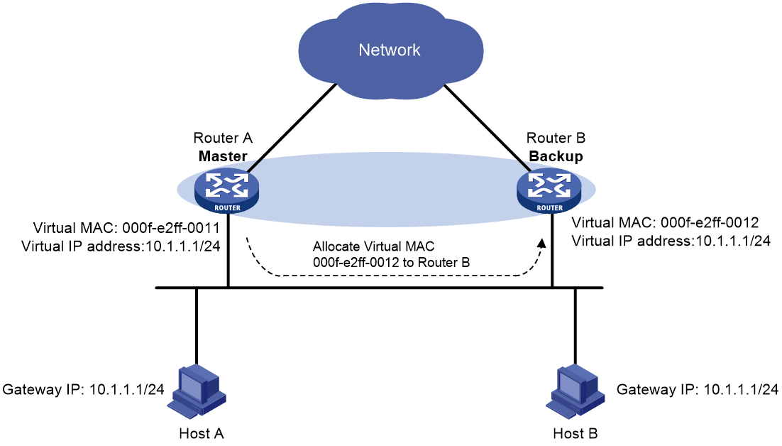
2. When an ARP request arrives, the master (Router A) selects a virtual MAC address based on the load balancing algorithm to answer the ARP request. In this example, Router A returns the virtual MAC address of itself in response to the ARP request from Host A. Router A returns the virtual MAC address of Router B in response to the ARP request from Host B. See Figure 28.
Figure 28 Answering ARP requests
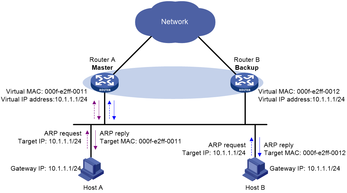
3. Each host sends packets to the returned MAC address. As shown in Figure 29, Host A sends packets to Router A and Host B sends packets to Router B.
Figure 29 Sending packets to different routers for forwarding
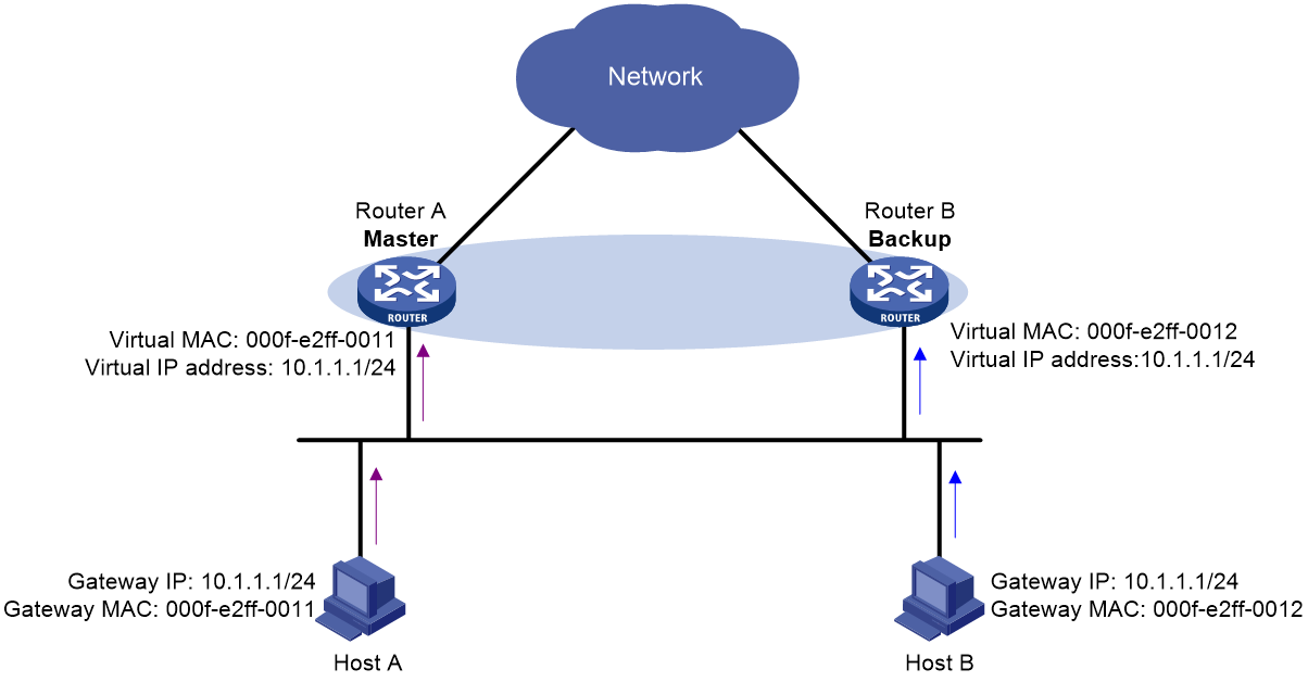
In the ARP reply sent by the master, the source MAC address in the Ethernet header is different from the sender MAC address in the message body. For the Layer 2 device to forward the ARP packet, follow these configuration guidelines on the Layer 2 device:
· Do not enable ARP packet source MAC address consistency check.
· Do not specify the src-mac keyword when you enable ARP packet validity check for ARP detection.
For more information about ARP packet source MAC address consistency check and ARP detection, see Security Configuration Guide.
Virtual forwarder
Virtual forwarder creation
Virtual MAC addresses enable traffic distribution across routers in a VRRP group. To enable routers in the VRRP group to forward packets, VFs must be created on them. Each VF is associated with a virtual MAC address in the VRRP group and forwards packets that are sent to this virtual MAC address.
VFs are created on routers in a VRRP group, as follows:
1. The master assigns virtual MAC addresses to all routers in the VRRP group. Each member router creates a VF for this MAC address and becomes the owner of this VF.
2. Each VF owner advertises its VF information to the other member routers.
3. After receiving the VF advertisement, each of the other routers creates the advertised VF.
Eventually, every member router maintains one VF for each virtual MAC address in the VRRP group.
VF weight and priority
The weight of a VF indicates the forwarding capability of a VF. A higher weight means higher forwarding capability. When the weight is lower than the lower limit of failure, the VF cannot forward packets.
The priority of a VF determines the VF state. Among the VFs created on different member routers for the same virtual MAC address, the VF with the highest priority is in active state. This VF, known as the active virtual forwarder (AVF), forwards packets. All other VFs listen to the state of the AVF and are known as the listening virtual forwarders (LVFs). VF priority is in the range of 0 to 255, where 255 is reserved for the VF owner. When the weight of a VF owner is higher than or equal to the lower limit of failure, the priority of the VF owner is 255.
The priority of a VF is calculated based on its weight.
· If the VF weight is higher than or equal to the lower limit of failure, the following VF priorities apply:
¡ On a VF owner, the VF priority is 255.
¡ On a non-VF owner, the VF priority is calculated as weight/(number of local AVFs + 1).
· If the VF weight is lower than the lower limit of failure, the VF priority is 0.
VF backup
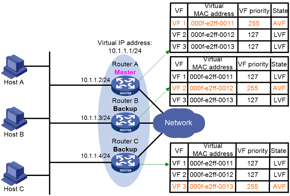
Figure 30 shows the VF table on each router in the VRRP group and how the VFs back up one another. The master, Router A, assigns virtual MAC addresses 000f-e2ff-0011, 000f-e2ff-0012, and 000f-e2ff-0013 to itself, Router B, and Router C, respectively. Each router creates VF 1, VF 2, and VF 3 for virtual MAC addresses 000f-e2ff-0011, 000f-e2ff-0012, and 000f-e2ff-0013, respectively. The VFs for the same virtual MAC address on different routers back up one another. For example, the VF 1 instances on Router A, Router B, and Router C back up one another.
· The VF 1 instances on Router B and Router C have a priority of 255/(1 + 1), or 127. Because their priorities are lower than the priority of the VF 1 instance on Router A, they act as LVFs. These LVFs listen to the state of the VF 1 instance on Router A.
· When the VF 1 instance on Router A fails, the VF 1 instances on Router B and Router C elect the one with higher priority as the new AVF. This AVF forwards packets destined for virtual MAC address 000f-e2ff-0011. If the two LVFs' priorities are the same, the LVF with a greater device MAC address becomes the new AVF.
A VF always operates in preemptive mode. When an LVF finds its priority value higher than the one advertised by the AVF, the LVF declares itself as the AVF.
VF timers
When the AVF on a router fails, the new AVF on another router creates the following timers for the failed AVF:
· Redirect timer—Before this timer expires, the master still uses the virtual MAC address corresponding to the failed AVF to respond to ARP/ND requests from hosts. The VF owner can share traffic load if the VF owner resumes normal operation within this time. When this timer expires, the master stops using the virtual MAC address corresponding to the failed AVF to respond to ARP/ND requests from hosts.
· Timeout timer—The duration after which the new AVF takes over responsibilities of the failed VF owner. Before this timer expires, all routers in the VRRP group keep the VFs that correspond to the failed AVF. The new AVF forwards packets destined for the virtual MAC address of the failed AVF. When this timer expires, all routers in the VRRP group remove the VFs that correspond to the failed AVF, including the new AVF. Packets destined for the virtual MAC address of the failed AVF are not forwarded any longer.
VF tracking
An AVF forwards packets destined for the MAC address of the AVF. If the AVF's upstream link fails but no LVF takes over, the hosts that use the AVF's MAC address as their gateway MAC address cannot access the external network.
The VF tracking function can solve this problem. You can use NQA or BFD to monitor the upstream link state of the VF owner, and associate the VFs with NQA or BFD through the tracking function. This enables the collaboration between VRRP and NQA or BFD through the Track module. When the upstream link fails, the state of the track entry changes to Negative. The weights of the VFs (including the AVF) on the router decrease by a specific value. The corresponding LVF with a higher priority on another router becomes the AVF and forwards packets.
Protocols and standards
· RFC 3768, Virtual Router Redundancy Protocol (VRRP)
· RFC 5798, Virtual Router Redundancy Protocol (VRRP) Version 3 for IPv4 and IPv6
Configuring IPv4 VRRP
VRRP cannot be configured on member ports of aggregation groups.
IPv4 VRRP configuration task list
|
Tasks at a glance |
Remarks |
|
(Required.) Specifying an IPv4 VRRP operating mode |
N/A |
|
(Optional.) Specifying the IPv4 VRRP version |
N/A |
|
(Required.) Creating a VRRP group and assigning a virtual IP address |
N/A |
|
(Optional.) Configuring the router priority, preemptive mode, and tracking function |
N/A |
|
N/A |
|
|
(Optional.) Configuring VF tracking |
This configuration applies only to VRRP load balancing mode. |
|
(Optional.) Enabling SNMP notifications for VRRP |
N/A |
|
(Optional.) Disabling an IPv4 VRRP group |
N/A |
Specifying an IPv4 VRRP operating mode
A VRRP group can operate in either of the following modes:
· Standard mode—Only the master can forward packets.
· Load balancing mode—All members that have an AVF can forward packets.
After an IPv4 VRRP operating mode is configured on a router, all IPv4 VRRP groups on the router operate in the specified operating mode.
To specify an IPv4 VRRP operating mode:
|
Step |
Command |
Remarks |
|
1. Enter system view. |
system-view |
N/A |
|
2. Specify an IPv4 VRRP operating mode. |
· Specify the standard mode: · Specify the load balancing mode: |
By default, VRRP operates in standard mode. |
Specifying the IPv4 VRRP version
The VRRP version on all routers in an IPv4 VRRP group must be the same.
To specify the version of IPv4 VRRP:
|
Step |
Command |
Remarks |
|
1. Enter system view. |
system-view |
N/A |
|
2. Enter interface view. |
interface interface-type interface-number |
N/A |
|
3. Specify the version of VRRP. |
vrrp version version-number |
By default, VRRPv3 is used. |
Creating a VRRP group and assigning a virtual IP address
A VRRP group can operate correctly after you create it and assign a minimum of one virtual IP address to it. You can configure multiple virtual IP addresses for the VRRP group on an interface that connects to multiple subnets for router backup on different subnets.
Configuration guidelines
· In VRRP load balancing mode, the device supports a maximum of MaxVRNum/N VRRP groups. MaxVRNum refers to the maximum number of VRRP groups supported by the device in VRRP standard mode. N refers to the number of devices in the VRRP group.
· When VRRP is operating in standard mode, the virtual IP address of a VRRP group can be either of the following addresses:
¡ Unused IP address on the subnet where the VRRP group resides.
¡ IP address of an interface on a router in the VRRP group.
· In load balancing mode, the virtual IP address of a VRRP group can be any unassigned IP address of the subnet where the VRRP group resides. It cannot be the IP address of any interface in the VRRP group. No IP address owner can exist in a VRRP group.
· On an IP address owner, as a best practice, do not use the network command to enable OSPF on the interface owning the virtual IP address of the VRRP group. For more information about the network command, see Layer 3—IP Routing Command Reference.
· If you create an IPv4 VRRP group without assigning virtual IP address to it, the VRRP group stays in inactive state and does not function.
· Removal of the VRRP group on the IP address owner causes IP address collision. To avoid the collision, change the IP address of the interface on the IP address owner before you remove the VRRP group from the interface.
· The virtual IP address of an IPv4 VRRP group and the downlink interface IP address of the VRRP group must be in the same subnet. Otherwise, the hosts in the subnet might fail to access external networks.
Configuration procedure
To create a VRRP group and assign a virtual IP address:
|
Step |
Command |
Remarks |
|
1. Enter system view. |
system-view |
N/A |
|
2. Enter interface view. |
interface interface-type interface-number |
N/A |
|
3. Create a VRRP group and assign a virtual IP address. |
vrrp vrid virtual-router-id virtual-ip virtual-address |
By default, no VRRP groups exist. |
Configuring the router priority, preemptive mode, and tracking function
The router priority determines which router in the VRRP group acts as the master. The preemptive mode enables a backup to take over as the master when it detects that it has a higher priority than the current master. The tracking function decreases the router priority or enables the backup to take over as the master when the state of the monitored track entry transits to Negative.
Configuration guidelines
· The running priority of an IP address owner is always 255, and you do not need to configure it. An IP address owner always operates in preemptive mode.
· If you configure the vrrp vrid track priority reduced or vrrp vrid track switchover command on an IP address owner, the configuration does not take effect until the router becomes a non-IP address owner.
Configuration procedure
To configure the router priority, preemptive mode, and tracking function:
|
Step |
Command |
Remarks |
|
1. Enter system view. |
system-view |
N/A |
|
2. Enter interface view. |
interface interface-type interface-number |
N/A |
|
3. Set the priority of the router in the VRRP group. |
vrrp vrid virtual-router-id priority priority-value |
The default setting is 100. |
|
4. Enable the preemptive mode for the router in a VRRP group and set the preemption delay time. |
vrrp vrid virtual-router-id preempt-mode [ delay delay-value ] |
By default, the router in a VRRP group operates in preemptive mode and the preemption delay time is 0 centiseconds, which means an immediate preemption. |
|
5. Associate a VRRP group with a track entry. |
vrrp vrid virtual-router-id track track-entry-number { forwarder-switchover member-ip ip-address | priority reduced [ priority-reduced ] | switchover | weight reduced [ weight-reduced ] } |
By default, a VRRP group is not associated with any track entries. |
Configuring IPv4 VRRP packet attributes
Configuration guidelines
· You can configure different authentication modes and authentication keys for VRRP groups on an interface. However, members of the same VRRP group must use the same authentication mode and authentication key.
· In VRRPv2, all routers in a VRRP group must have the same VRRP advertisement interval.
· In VRRPv3, authentication mode and authentication key settings do not take effect.
· In VRRPv3, routers in an IPv4 VRRP group can have different intervals for sending VRRP advertisements. The master in the VRRP group sends VRRP advertisements at specified intervals, and carries the interval in the advertisements. After a backup receives the advertisement, it records the interval in the advertisement. If the backup does not receive a VRRP advertisement before the timer (3 x recorded interval + Skew_Time) expires, it regards the master as failed and takes over.
Configuration procedure
To configure VRRP packet attributes:
|
Step |
Command |
Remarks |
|
1. Enter system view. |
system-view |
N/A |
|
2. Enter interface view. |
interface interface-type interface-number |
N/A |
|
3. Configure the authentication mode and authentication key for an IPv4 VRRP group to send and receive VRRP packets. |
vrrp vrid virtual-router-id authentication-mode { md5 | simple } { cipher | plain } string |
By default, authentication is disabled. |
|
4. Set the interval at which the master in an IPv4 VRRP group sends VRRP advertisements. |
vrrp vrid virtual-router-id timer advertise adver-interval |
The default setting is 100 centiseconds. As a best practice to maintain system stability, set the VRRP advertisement interval to be greater than 100 centiseconds. |
|
5. Specify the source interface for receiving and sending VRRP packets. |
vrrp vrid virtual-router-id source-interface interface-type interface-number |
By default, the source interface for receiving and sending VRRP packets is not specified. The interface where the VRRP group resides sends and receives VRRP packets. |
|
6. Enable TTL check for IPv4 VRRP packets. |
vrrp check-ttl enable |
By default, TTL check for IPv4 VRRP packets is enabled. |
|
7. Return to system view. |
quit |
N/A |
|
8. Set a DSCP value for VRRP packets. |
vrrp dscp dscp-value |
The DSCP value identifies the packet priority during transmission. By default, the DSCP value for VRRP packets is 48. |
Configuring VF tracking
You can configure VF tracking in both standard mode and load balancing mode, but the function takes effect only in load balancing mode.
In load balancing mode, you can establish the collaboration between the VFs and NQA or BFD through the tracking function. When the state of the track entry transits to Negative, the weights of all VFs in the VRRP group on the router decrease by a specific value. When the state of the track entry transits to Positive or Notready, the original weight values of the VFs restore.
Configuration guidelines
· By default, the weight of a VF is 255, and its lower limit of failure is 10.
· When the weight of a VF owner is higher than or equal to the lower limit of failure, its priority is always 255. The priority does not change with the weight. When the upstream link of the VF owner fails, an LVF must take over as the AVF. The switchover happens when the weight of the VF owner drops below the lower limit of failure. This requires that the reduced weight for the VF owner be higher than 245.
Configuration procedure
To configure VF tracking:
|
Step |
Command |
Remarks |
|
1. Enter system view. |
system-view |
N/A |
|
2. Enter interface view. |
interface interface-type interface-number |
N/A |
|
3. Configure the VFs in a VRRP group to monitor a track entry. |
vrrp vrid virtual-router-id track track-entry-number { forwarder-switchover member-ip ip-address | priority reduced [ priority-reduced ] | switchover | weight reduced [ weight-reduced ] } |
By default, no track entry is specified. |
Enabling SNMP notifications for VRRP
To report critical VRRP events to an NMS, enable SNMP notifications for VRRP. For VRRP event notifications to be sent correctly, you must also configure SNMP on the device. For more information about SNMP configuration, see the network management and monitoring configuration guide for the device.
To enable SNMP notifications for VRRP:
|
Step |
Command |
Remarks |
|
1. Enter system view. |
system-view |
N/A |
|
2. Enable SNMP notifications for VRRP. |
snmp-agent trap enable vrrp [ auth-failure | new-master ] |
By default, SNMP notifications for VRRP are enabled. |
Disabling an IPv4 VRRP group
You can temporarily disable an IPv4 VRRP group. After being disabled, the VRRP group stays in initialized state, and its configurations remain unchanged. You can change the configuration of a VRRP group when the VRRP group is disabled. Your changes take effect when you enable the VRRP group again.
To disable an IPv4 VRRP group:
|
Step |
Command |
Remarks |
|
1. Enter system view. |
system-view |
N/A |
|
2. Enter interface view. |
interface interface-type interface-number |
N/A |
|
3. Disable a VRRP group. |
vrrp vrid virtual-router-id shutdown |
By default, a VRRP group is enabled. |
Displaying and maintaining IPv4 VRRP
Execute display commands in any view and the reset command in user view.
|
Task |
Command |
|
Display states of IPv4 VRRP groups. |
display vrrp [ interface interface-type interface-number [ vrid virtual-router-id ] ] [ verbose ] |
|
Display statistics for IPv4 VRRP groups. |
display vrrp statistics [ interface interface-type interface-number [ vrid virtual-router-id ] ] |
|
Clear statistics for IPv4 VRRP groups. |
reset vrrp statistics [ interface interface-type interface-number [ vrid virtual-router-id ] ] |
Configuring IPv6 VRRP
This section describes how to configure IPv6 VRRP.
IPv6 VRRP configuration task list
|
Tasks at a glance |
Remarks |
|
(Required.) Specifying an IPv6 VRRP operating mode |
N/A |
|
(Required.) Creating a VRRP group and assigning a virtual IPv6 address |
N/A |
|
(Optional.) Configuring the router priority, preemptive mode, and tracking function |
N/A |
|
(Optional.) Configuring VF tracking |
This configuration applies only to VRRP load balancing mode. |
|
(Optional.) Configuring IPv6 VRRP packet attributes |
N/A |
|
(Optional.) Disabling an IPv6 VRRP group |
N/A |
Specifying an IPv6 VRRP operating mode
A VRRP group can operate in either of the following modes:
· Standard mode—Only the master can forward packets.
· Load balancing mode—All members that have an AVF can forward packets.
After the IPv6 VRRP operating mode is specified on a router, all IPv6 VRRP groups on the router operate in the specified operating mode.
To specify an IPv6 VRRP operating mode:
|
Step |
Command |
Remarks |
|
1. Enter system view. |
system-view |
N/A |
|
2. Specify an IPv6 VRRP operating mode. |
· Specify the standard mode: · Specify the load balancing mode: |
By default, VRRP operates in standard mode. |
Creating a VRRP group and assigning a virtual IPv6 address
Configuration guidelines
· On an IP address owner, as a best practice, do not use the ospfv3 area command to enable OSPF on the interface owning the virtual IPv6 address of the VRRP group. For more information about the ospfv3 area command, see Layer 3—IP Routing Command Reference.
· In load balancing mode, the virtual IPv6 address of a VRRP group cannot be the same as the IPv6 address of any interface in the VRRP group.
· In VRRP load balancing mode, the device supports a maximum of MaxVRNum/N VRRP groups. MaxVRNum refers to the maximum number of VRRP groups supported by the device in VRRP standard mode. N refers to the number of devices in the VRRP group.
· If you create an IPv6 VRRP group without assigning virtual IPv6 address to it, the VRRP group stays in inactive state and does not function.
· Removal of the VRRP group on the IP address owner causes IP address collision. To avoid the collision, change the IPv6 address of the interface on the IP address owner before you remove the VRRP group from the interface.
· The virtual IPv6 address of an IPv6 VRRP group and the downlink interface IPv6 address of the VRRP group must be in the same subnet. Otherwise, the hosts in the subnet might fail to access external networks.
Configuration procedure
To create a VRRP group and assign a virtual IPv6 address:
|
Step |
Command |
Remarks |
|
1. Enter system view. |
system-view |
N/A |
|
2. Enter interface view. |
interface interface-type interface-number |
N/A |
|
3. Create a VRRP group and assign a virtual IPv6 address, which is a link-local address. |
vrrp ipv6 vrid virtual-router-id virtual-ip virtual-address link-local |
By default, no VRRP groups exist. The first virtual IPv6 address that you assign to an IPv6 VRRP group must be a link-local address. It must be the last address you remove. Only one link local address is allowed in a VRRP group. |
|
4. (Optional.) Assign a virtual IPv6 address, which is a global unicast address. |
vrrp ipv6 vrid virtual-router-id virtual-ip virtual-address |
By default, no global unicast address is assigned for an IPv6 VRRP group. |
Configuring the router priority, preemptive mode, and tracking function
Configuration guidelines
· The running priority of an IP address owner is always 255, and you do not need to configure it. An IP address owner always operates in preemptive mode.
· If you configure the vrrp ipv6 vrid track priority reduced or vrrp ipv6 vrid track switchover command on an IP address owner, the configuration does not take effect until the router becomes a non-IP address owner.
· When the track entry changes from Negative to Positive or Notready, the router automatically restores its priority or the failed master router becomes the master again.
Configuration procedure
To configure the router priority, preemptive mode, and tracking function:
|
Step |
Command |
Remarks |
|
1. Enter system view. |
system-view |
N/A |
|
2. Enter interface view. |
interface interface-type interface-number |
N/A |
|
3. Set the priority of the router in the VRRP group. |
vrrp ipv6 vrid virtual-router-id priority priority-value |
The default setting is 100. |
|
4. Enable the preemptive mode for the router in a VRRP group and set the preemption delay time. |
vrrp ipv6 vrid virtual-router-id preempt-mode [ delay delay-value ] |
By default, the router in a VRRP group operates in preemptive mode and the preemption delay time is 0 centiseconds, which means an immediate preemption. |
|
5. Associate a VRRP group with a track entry. |
vrrp ipv6 vrid virtual-router-id track track-entry-number { forwarder-switchover member-ip ipv6-address | priority reduced [ priority-reduced ] | switchover | weight reduced [ weight-reduced ] } |
By default, a VRRP group is not associated with any track entries. |
Configuring VF tracking
You can configure VF tracking in both standard mode and load balancing mode, but the function takes effect only in load balancing mode.
In load balancing mode, you can configure the VFs in a VRRP group to monitor a track entry. When the state of the track entry transits to Negative, the weights of all VFs in the VRRP group on the router decrease by a specific value. When the state of the track entry transits to Positive or Notready, the original weights of the VFs restore.
Configuration guidelines
· By default, the weight of a VF is 255, and its lower limit of failure is 10.
· When the weight of a VF owner is higher than or equal to the lower limit of failure, its priority is always 255. The priority does not change with the weight. When the upstream link of the VF owner fails, an LVF must take over as the AVF. The switchover happens when the weight of the VF owner drops below the lower limit of failure. This requires that the reduced weight for the VF owner be higher than 245.
Configuration procedure
To configure VF tracking:
|
Step |
Command |
Remarks |
|
1. Enter system view. |
system-view |
N/A |
|
2. Enter interface view. |
interface interface-type interface-number |
N/A |
|
3. Configure the VFs in a VRRP group to monitor a track entry. |
vrrp ipv6 vrid virtual-router-id track track-entry-number { forwarder-switchover member-ip ipv6-address | priority reduced [ priority-reduced ] | switchover | weight reduced [ weight-reduced ] } |
By default, no track entry is specified. |
Configuring IPv6 VRRP packet attributes
This section describes how to configure IPv6 VRRP packet attributes.
Configuration guidelines
· The routers in an IPv6 VRRP group can have different intervals for sending VRRP advertisements. The master in the VRRP group sends VRRP advertisements at the specified interval and carries the interval attribute in the advertisements. After a backup receives the advertisement, it records the interval in the advertisement. If the backup does not receive a VRRP advertisement before the timer (3 x recorded interval + Skew_Time) expires, it regards the master as failed and takes over.
· A high volume of network traffic might cause a backup to fail to receive VRRP advertisements from the master within the specified time. As a result, an unexpected master switchover occurs. To solve this problem, configure a larger interval.
Configuration procedure
To configure the IPv6 VRRP packet attribute:
|
Step |
Command |
Remarks |
|
1. Enter system view. |
system-view |
N/A |
|
2. Enter interface view. |
interface interface-type interface-number |
N/A |
|
3. Set the IPv6 VRRP advertisement interval. |
vrrp ipv6 vrid virtual-router-id timer advertise adver-interval |
The default setting is 100 centiseconds. As a best practice to maintain system stability, set the VRRP advertisement interval to be greater than 100 centiseconds. |
|
4. Return to system view. |
quit |
N/A |
|
5. Set a DSCP value for IPv6 VRRP packets. |
vrrp ipv6 dscp dscp-value |
The DSCP value identifies the packet priority during transmission. By default, the DSCP value for IPv6 VRRP packets is 56. |
Disabling an IPv6 VRRP group
You can temporarily disable an IPv6 VRRP group. After being disabled, the VRRP group stays in initialized state, and its configurations remain unchanged. You can change the configuration of a VRRP group when it is disabled. Your changes take effect when you enable the VRRP group again.
To disable an IPv6 VRRP group:
|
Step |
Command |
Remarks |
|
1. Enter system view. |
system-view |
N/A |
|
2. Enter interface view. |
interface interface-type interface-number |
N/A |
|
3. Disable an IPv6 VRRP group. |
vrrp ipv6 vrid virtual-router-id shutdown |
By default, an IPv6 VRRP group is enabled. |
Displaying and maintaining IPv6 VRRP
Execute display commands in any view and the reset command in user view.
|
Task |
Command |
|
Display the states of IPv6 VRRP groups. |
display vrrp ipv6 [ interface interface-type interface-number [ vrid virtual-router-id ] ] [ verbose ] |
|
Display statistics for IPv6 VRRP groups. |
display vrrp ipv6 statistics [ interface interface-type interface-number [ vrid virtual-router-id ] ] |
|
Clear statistics for IPv6 VRRP groups. |
reset vrrp ipv6 statistics [ interface interface-type interface-number [ vrid virtual-router-id ] ] |
IPv4 VRRP configuration examples
Single VRRP group configuration example
Network requirements
As shown in Figure 31, Switch A and Switch B form a VRRP group. They use the virtual IP address 10.1.1.111/24 to provide gateway service for the subnet where Host A resides.
Switch A operates as the master to forward packets from Host A to Host B. When Switch A fails, Switch B takes over to forward packets for Host A.
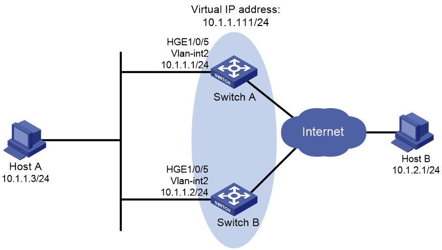
Configuration procedure
1. Configure Switch A:
# Configure VLAN 2.
<SwitchA> system-view
[SwitchA] vlan 2
[SwitchA-vlan2] port hundredgige 1/0/5
[SwitchA-vlan2] quit
[SwitchA] interface vlan-interface 2
[SwitchA-Vlan-interface2] ip address 10.1.1.1 255.255.255.0
# Create VRRP group 1 on VLAN-interface 2, and set its virtual IP address to 10.1.1.111.
[SwitchA-Vlan-interface2] vrrp vrid 1 virtual-ip 10.1.1.111
# Assign Switch A a higher priority than Switch B in VRRP group 1, so Switch A can become the master.
[SwitchA-Vlan-interface2] vrrp vrid 1 priority 110
# Configure Switch A to operate in preemptive mode, so it can become the master whenever it operates correctly. Set the preemption delay to 5000 centiseconds to avoid frequent status switchover.
[SwitchA-Vlan-interface2] vrrp vrid 1 preempt-mode delay 5000
2. Configure Switch B:
# Configure VLAN 2.
<SwitchB> system-view
[SwitchB] vlan 2
[SwitchB-Vlan2] port hundredgige 1/0/5
[SwitchB-vlan2] quit
[SwitchB] interface vlan-interface 2
[SwitchB-Vlan-interface2] ip address 10.1.1.2 255.255.255.0
# Create VRRP group 1 on VLAN-interface 2, and set its virtual IP address to 10.1.1.111.
[SwitchB-Vlan-interface2] vrrp vrid 1 virtual-ip 10.1.1.111
# Set the priority of Router B to 100 in VRRP group 1.
[SwitchB-Vlan-interface2] vrrp vrid 1 priority 100
# Configure Switch B to operate in preemptive mode, and set the preemption delay to 5000 centiseconds.
[SwitchB-Vlan-interface2] vrrp vrid 1 preempt-mode delay 5000
Verifying the configuration
# Ping Host B from Host A. (Details not shown.)
# Display detailed information about VRRP group 1 on Switch A.
[SwitchA-Vlan-interface2] display vrrp verbose
IPv4 Virtual Router Information:
Running Mode : Standard
Total number of virtual routers : 1
Interface Vlan-interface2
VRID : 1 Adver Timer : 100
Admin Status : Up State : Master
Config Pri : 110 Running Pri : 110
Preempt Mode : Yes Delay Time : 5000
Auth Type : None
Virtual IP : 10.1.1.111
Virtual MAC : 0000-5e00-0101
Master IP : 10.1.1.1
# Display detailed information about VRRP group 1 on Switch B.
[SwitchB-Vlan-interface2] display vrrp verbose
IPv4 Virtual Router Information:
Running Mode : Standard
Total number of virtual routers : 1
Interface Vlan-interface2
VRID : 1 Adver Timer : 100
Admin Status : Up State : Backup
Config Pri : 100 Running Pri : 100
Preempt Mode : Yes Delay Time : 5000
Become Master : 401ms left
Auth Type : None
Virtual IP : 10.1.1.111
Master IP : 10.1.1.1
The output shows that Switch A is operating as the master in VRRP group 1 to forward packets from Host A to Host B.
# Disconnect the link between Host A and Switch A, and verify that Host A can still ping Host B. (Details not shown.)
# Display detailed information about VRRP group 1 on Switch B.
[SwitchB-Vlan-interface2] display vrrp verbose
IPv4 Virtual Router Information:
Running Mode : Standard
Total number of virtual routers : 1
Interface Vlan-interface2
VRID : 1 Adver Timer : 100
Admin Status : Up State : Master
Config Pri : 100 Running Pri : 100
Preempt Mode : Yes Delay Time : 5000
Auth Type : None
Virtual IP : 10.1.1.111
Virtual MAC : 0000-5e00-0101
Master IP : 10.1.1.2
The output shows that when Switch A fails, Switch B takes over to forward packets from Host A to Host B.
# Recover the link between Host A and Switch A, and display detailed information about VRRP group 1 on Switch A.
[SwitchA-Vlan-interface2] display vrrp verbose
IPv4 Virtual Router Information:
Running Mode : Standard
Total number of virtual routers : 1
Interface Vlan-interface2
VRID : 1 Adver Timer : 100
Admin Status : Up State : Master
Config Pri : 110 Running Pri : 110
Preempt Mode : Yes Delay Time : 5000
Auth Type : None
Virtual IP : 10.1.1.111
Virtual MAC : 0000-5e00-0101
Master IP : 10.1.1.1
The output shows that after Switch A resumes normal operation, it becomes the master to forward packets from Host A to Host B.
Multiple VRRP groups configuration example
Network requirements
As shown in Figure 32, Switch A and Switch B form two VRRP groups. VRRP group 1 uses the virtual IP address 10.1.1.100/25 to provide gateway service for hosts in VLAN 2, and VRRP group 2 uses the virtual IP address 10.1.1.200/25 to provide gateway service for hosts in VLAN 3.
Assign a higher priority to Switch A than Switch B in VRRP group 1, but a lower priority in VRRP group 2. Traffic from VLAN 2 and VLAN 3 can then be distributed between the two switches. When one of the switches fails, the healthy switch provides gateway service for both VLANs.
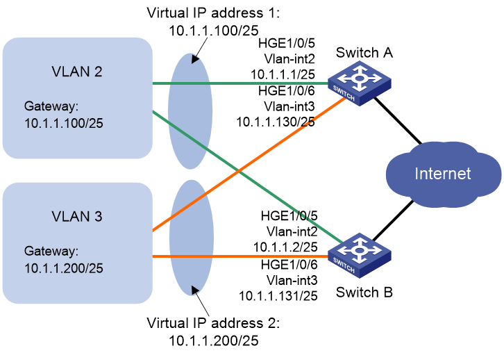
Configuration procedure
1. Configure Switch A:
# Configure VLAN 2.
<SwitchA> system-view
[SwitchA] vlan 2
[SwitchA-vlan2] port hundredgige 1/0/5
[SwitchA-vlan2] quit
[SwitchA] interface vlan-interface 2
[SwitchA-Vlan-interface2] ip address 10.1.1.1 255.255.255.128
# Create VRRP group 1, and set its virtual IP address to 10.1.1.100.
[SwitchA-Vlan-interface2] vrrp vrid 1 virtual-ip 10.1.1.100
# Assign Switch A a higher priority than Switch B in VRRP group 1, so Switch A can become the master in the group.
[SwitchA-Vlan-interface2] vrrp vrid 1 priority 110
[SwitchA-Vlan-interface2] quit
# Configure VLAN 3.
[SwitchA] vlan 3
[SwitchA-vlan3] port hundredgige 1/0/6
[SwitchA-vlan3] quit
[SwitchA] interface vlan-interface 3
[SwitchA-Vlan-interface3] ip address 10.1.1.130 255.255.255.128
# Create VRRP group 2, and set its virtual IP address to 10.1.1.200.
[SwitchA-Vlan-interface3] vrrp vrid 2 virtual-ip 10.1.1.200
2. Configure Switch B:
# Configure VLAN 2.
<SwitchB> system-view
[SwitchB] vlan 2
[SwitchB-vlan2] port hundredgige 1/0/5
[SwitchB-vlan2] quit
[SwitchB] interface vlan-interface 2
[SwitchB-Vlan-interface2] ip address 10.1.1.2 255.255.255.128
# Create VRRP group 1, and set its virtual IP address to 10.1.1.100.
[SwitchB-Vlan-interface2] vrrp vrid 1 virtual-ip 10.1.1.100
[SwitchB-Vlan-interface2] quit
# Configure VLAN 3.
[SwitchB] vlan 3
[SwitchB-vlan3] port hundredgige 1/0/6
[SwitchB-vlan3] quit
[SwitchB] interface vlan-interface 3
[SwitchB-Vlan-interface3] ip address 10.1.1.131 255.255.255.128
# Create VRRP group 2, and set its virtual IP address to 10.1.1.200.
[SwitchB-Vlan-interface3] vrrp vrid 2 virtual-ip 10.1.1.200
# Assign Switch B a higher priority than Switch A in VRRP group 2, so Switch B can become the master in the group.
[SwitchB-Vlan-interface3] vrrp vrid 2 priority 110
Verifying the configuration
# Display detailed information about the VRRP groups on Switch A.
[SwitchA-Vlan-interface3] display vrrp verbose
IPv4 Virtual Router Information:
Running Mode : Standard
Total number of virtual routers : 2
Interface Vlan-interface2
VRID : 1 Adver Timer : 100
Admin Status : Up State : Master
Config Pri : 110 Running Pri : 110
Preempt Mode : Yes Delay Time : 0
Auth Type : None
Virtual IP : 10.1.1.100
Virtual MAC : 0000-5e00-0101
Master IP : 10.1.1.1
Interface Vlan-interface3
VRID : 2 Adver Timer : 100
Admin Status : Up State : Backup
Config Pri : 100 Running Pri : 100
Preempt Mode : Yes Delay Time : 0
Become Master : 203ms left
Auth Type : None
Virtual IP : 10.1.1.200
Master IP : 10.1.1.131
# Display detailed information about the VRRP groups on Switch B.
[SwitchB-Vlan-interface3] display vrrp verbose
IPv4 Virtual Router Information:
Running Mode : Standard
Total number of virtual routers : 2
Interface Vlan-interface2
VRID : 1 Adver Timer : 100
Admin Status : Up State : Backup
Config Pri : 100 Running Pri : 100
Preempt Mode : Yes Delay Time : 0
Become Master : 211ms left
Auth Type : None
Virtual IP : 10.1.1.100
Master IP : 10.1.1.1
Interface Vlan-interface3
VRID : 2 Adver Timer : 100
Admin Status : Up State : Master
Config Pri : 110 Running Pri : 110
Preempt Mode : Yes Delay Time : 0
Auth Type : None
Virtual IP : 10.1.1.200
Virtual MAC : 0000-5e00-0102
Master IP : 10.1.1.131
The output shows the following information:
· Switch A is operating as the master in VRRP group 1 to forward Internet traffic for hosts that use the default gateway 10.1.1.100/25.
· Switch B is operating as the master in VRRP group 2 to forward Internet traffic for hosts that use the default gateway 10.1.1.200/25.
VRRP load balancing configuration example
Network requirements
As shown in Figure 33, Switch A, Switch B, and Switch C form a load-balanced VRRP group. They use the virtual IP address 10.1.1.1/24 to provide gateway service for subnet 10.1.1.0/24.
Configure VFs on Switch A, Switch B, and Switch C to monitor their respective VLAN-interface 3. When the interface on any one of them fails, the weights of the VFs on the problematic switch decrease so another AVF can take over.
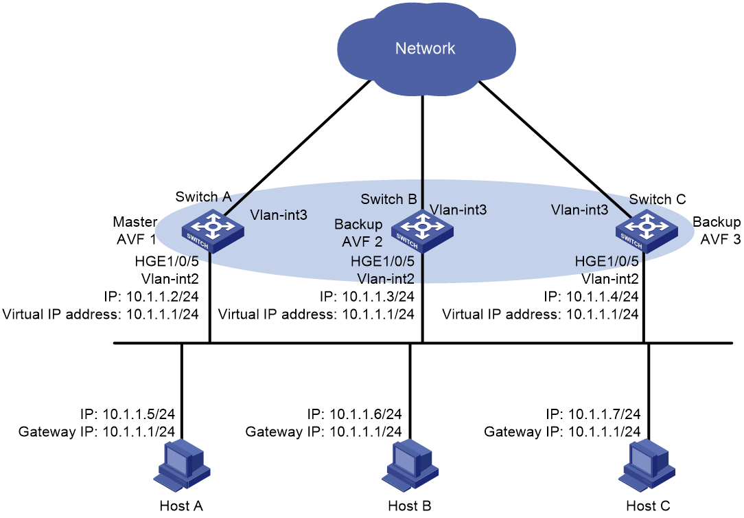
Configuration procedure
1. Configure Switch A:
# Configure VLAN 2.
<SwitchA> system-view
[SwitchA] vlan 2
[SwitchA-vlan2] port hundredgige 1/0/5
[SwitchA-vlan2] quit
# Configure VRRP to operate in load balancing mode.
[SwitchA] vrrp mode load-balance
# Create VRRP group 1, and set its virtual IP address to 10.1.1.1.
[SwitchA] interface vlan-interface 2
[SwitchA-Vlan-interface2] ip address 10.1.1.2 24
[SwitchA-Vlan-interface2] vrrp vrid 1 virtual-ip 10.1.1.1
# Assign Switch A the highest priority in VRRP group 1, so Switch A can become the master.
[SwitchA-Vlan-interface2] vrrp vrid 1 priority 120
# Configure Switch A to operate in preemptive mode, so it can become the master whenever it operates correctly. Set the preemption delay to 5000 centiseconds to avoid frequent status switchover.
[SwitchA-Vlan-interface2] vrrp vrid 1 preempt-mode delay 5000
[SwitchA-Vlan-interface2] quit
# Create track entry 1 to monitor the upstream link status of VLAN-interface 3. When the upstream link fails, the track entry transits to Negative.
[SwitchA] track 1 interface vlan-interface 3
# Configure the VFs in VRRP group 1 to monitor track entry 1, and decrease their weights by 250 when the track entry transits to Negative.
[SwitchA] interface vlan-interface 2
[SwitchA-Vlan-interface2] vrrp vrid 1 track 1 weight reduced 250
2. Configure Switch B:
# Configure VLAN 2.
<SwitchB> system-view
[SwitchB] vlan 2
[SwitchB-vlan2] port hundredgige 1/0/5
[SwitchB-vlan2] quit
# Configure VRRP to operate in load balancing mode.
[SwitchB] vrrp mode load-balance
# Create VRRP group 1, and set its virtual IP address to 10.1.1.1.
[SwitchB] interface vlan-interface 2
[SwitchB-Vlan-interface2] ip address 10.1.1.3 24
[SwitchB-Vlan-interface2] vrrp vrid 1 virtual-ip 10.1.1.1
# Assign Switch B a higher priority than Switch C in VRRP group 1, so Switch B can become the master when Switch A fails.
[SwitchB-Vlan-interface2] vrrp vrid 1 priority 110
# Configure Switch B to operate in preemptive mode, and set the preemption delay to 5000 centiseconds.
[SwitchB-Vlan-interface2] vrrp vrid 1 preempt-mode delay 5000
[SwitchB-Vlan-interface2] quit
# Create track entry 1 to monitor the upstream link status of VLAN-interface 3. When the upstream link fails, the track entry transits to Negative.
[SwitchB] track 1 interface vlan-interface 3
# Configure the VFs in VRRP group 1 to monitor track entry 1, and decrease their weights by 250 when the track entry transits to Negative.
[SwitchB] interface vlan-interface 2
[SwitchB-Vlan-interface2] vrrp vrid 1 track 1 weight reduced 250
3. Configure Switch C:
# Configure VLAN 2.
<SwitchC> system-view
[SwitchC] vlan 2
[SwitchC-vlan2] port hundredgige 1/0/5
[SwitchC-vlan2] quit
# Configure VRRP to operate in load balancing mode.
[SwitchC] vrrp mode load-balance
# Create VRRP group 1, and set its virtual IP address to 10.1.1.1.
[SwitchC] interface vlan-interface 2
[SwitchC-Vlan-interface2] ip address 10.1.1.4 24
[SwitchC-Vlan-interface2] vrrp vrid 1 virtual-ip 10.1.1.1
# Configure Switch C to operate in preemptive mode, and set the preemption delay to 5000 centiseconds.
[SwitchC-Vlan-interface2] vrrp vrid 1 preempt-mode delay 5000
[SwitchC-Vlan-interface2] quit
# Create track entry 1 to monitor the upstream link status of VLAN-interface 3. When the upstream link fails, the track entry transits to Negative.
[SwitchC] track 1 interface vlan-interface 3
# Configure the VFs in VRRP group 1 to monitor track entry 1, and decrease their weights by 250 when the track entry transits to Negative.
[SwitchC] interface vlan-interface 2
[SwitchC-Vlan-interface2] vrrp vrid 1 track 1 weight reduced 250
Verifying the configuration
# Verify that Host A can ping the external network. (Details not shown.)
# Display detailed information about VRRP group 1 on Switch A.
[SwitchA-Vlan-interface2] display vrrp verbose
IPv4 Virtual Router Information:
Running Mode : Load Balance
Total number of virtual routers : 1
Interface Vlan-interface2
VRID : 1 Adver Timer : 100
Admin Status : Up State : Master
Config Pri : 120 Running Pri : 120
Preempt Mode : Yes Delay Time : 5000
Auth Type : None
Virtual IP : 10.1.1.1
Member IP List : 10.1.1.2 (Local, Master)
10.1.1.3 (Backup)
10.1.1.4 (Backup)
Forwarder Information: 3 Forwarders 1 Active
Config Weight : 255
Running Weight : 255
Forwarder 01
State : Active
Virtual MAC : 000f-e2ff-0011 (Owner)
Owner ID : 0000-5e01-1101
Priority : 255
Active : local
Forwarder 02
State : Listening
Virtual MAC : 000f-e2ff-0012 (Learnt)
Owner ID : 0000-5e01-1103
Priority : 127
Active : 10.1.1.3
Forwarder 03
State : Listening
Virtual MAC : 000f-e2ff-0013 (Learnt)
Owner ID : 0000-5e01-1105
Priority : 127
Active : 10.1.1.4
Forwarder Weight Track Information:
Track Object : 1 State : Positive Weight Reduced : 250
# Display detailed information about VRRP group 1 on Switch B.
[SwitchB-Vlan-interface2] display vrrp verbose
IPv4 Virtual Router Information:
Running Mode : Load Balance
Total number of virtual routers : 1
Interface Vlan-interface2
VRID : 1 Adver Timer : 100
Admin Status : Up State : Backup
Config Pri : 110 Running Pri : 110
Preempt Mode : Yes Delay Time : 5000
Become Master : 410ms left
Auth Type : None
Virtual IP : 10.1.1.1
Member IP List : 10.1.1.3 (Local, Backup)
10.1.1.2 (Master)
10.1.1.4 (Backup)
Forwarder Information: 3 Forwarders 1 Active
Config Weight : 255
Running Weight : 255
Forwarder 01
State : Listening
Virtual MAC : 000f-e2ff-0011 (Learnt)
Owner ID : 0000-5e01-1101
Priority : 127
Active : 10.1.1.2
Forwarder 02
State : Active
Virtual MAC : 000f-e2ff-0012 (Owner)
Owner ID : 0000-5e01-1103
Priority : 255
Active : local
Forwarder 03
State : Listening
Virtual MAC : 000f-e2ff-0013 (Learnt)
Owner ID : 0000-5e01-1105
Priority : 127
Active : 10.1.1.4
Forwarder Weight Track Information:
Track Object : 1 State : Positive Weight Reduced : 250
# Display detailed information about VRRP group 1 on Switch C.
[SwitchC-Vlan-interface2] display vrrp verbose
IPv4 Virtual Router Information:
Running Mode : Load Balance
Total number of virtual routers : 1
Interface Vlan-interface2
VRID : 1 Adver Timer : 100
Admin Status : Up State : Backup
Config Pri : 100 Running Pri : 100
Preempt Mode : Yes Delay Time : 5000
Become Master : 401ms left
Auth Type : None
Virtual IP : 10.1.1.1
Member IP List : 10.1.1.4 (Local, Backup)
10.1.1.2 (Master)
10.1.1.3 (Backup)
Forwarder Information: 3 Forwarders 1 Active
Config Weight : 255
Running Weight : 255
Forwarder 01
State : Listening
Virtual MAC : 000f-e2ff-0011 (Learnt)
Owner ID : 0000-5e01-1101
Priority : 127
Active : 10.1.1.2
Forwarder 02
State : Listening
Virtual MAC : 000f-e2ff-0012 (Learnt)
Owner ID : 0000-5e01-1103
Priority : 127
Active : 10.1.1.3
Forwarder 03
State : Active
Virtual MAC : 000f-e2ff-0013 (Owner)
Owner ID : 0000-5e01-1105
Priority : 255
Active : local
Forwarder Weight Track Information:
Track Object : 1 State : Positive Weight Reduced : 250
The output shows that Switch A is the master in VRRP group 1, and each of the three switches has one AVF and two LVFs.
# Disconnect the link of VLAN-interface 3 on Switch A, and display detailed information about VRRP group 1 on Switch A.
[SwitchA-Vlan-interface2] display vrrp verbose
IPv4 Virtual Router Information:
Running Mode : Load Balance
Total number of virtual routers : 1
Interface Vlan-interface2
VRID : 1 Adver Timer : 100
Admin Status : Up State : Master
Config Pri : 120 Running Pri : 120
Preempt Mode : Yes Delay Time : 5000
Auth Type : None
Virtual IP : 10.1.1.1
Member IP List : 10.1.1.2 (Local, Master)
10.1.1.3 (Backup)
10.1.1.4 (Backup)
Forwarder Information: 3 Forwarders 0 Active
Config Weight : 255
Running Weight : 5
Forwarder 01
State : Initialize
Virtual MAC : 000f-e2ff-0011 (Owner)
Owner ID : 0000-5e01-1101
Priority : 0
Active : 10.1.1.4
Forwarder 02
State : Initialize
Virtual MAC : 000f-e2ff-0012 (Learnt)
Owner ID : 0000-5e01-1103
Priority : 0
Active : 10.1.1.3
Forwarder 03
State : Initialize
Virtual MAC : 000f-e2ff-0013 (Learnt)
Owner ID : 0000-5e01-1105
Priority : 0
Active : 10.1.1.4
Forwarder Weight Track Information:
Track Object : 1 State : Negative Weight Reduced : 250
# Display detailed information about VRRP group 1 on Switch C.
[SwitchC-Vlan-interface2] display vrrp verbose
IPv4 Virtual Router Information:
Running Mode : Load Balance
Total number of virtual routers : 1
Interface Vlan-interface2
VRID : 1 Adver Timer : 100
Admin Status : Up State : Backup
Config Pri : 100 Running Pri : 100
Preempt Mode : Yes Delay Time : 5000
Become Master : 401ms left
Auth Type : None
Virtual IP : 10.1.1.1
Member IP List : 10.1.1.4 (Local, Backup)
10.1.1.2 (Master)
10.1.1.3 (Backup)
Forwarder Information: 3 Forwarders 2 Active
Config Weight : 255
Running Weight : 255
Forwarder 01
State : Active
Virtual MAC : 000f-e2ff-0011 (Take Over)
Owner ID : 0000-5e01-1101
Priority : 85
Active : local
Forwarder 02
State : Listening
Virtual MAC : 000f-e2ff-0012 (Learnt)
Owner ID : 0000-5e01-1103
Priority : 85
Active : 10.1.1.3
Forwarder 03
State : Active
Virtual MAC : 000f-e2ff-0013 (Owner)
Owner ID : 0000-5e01-1105
Priority : 255
Active : local
Forwarder Weight Track Information:
Track Object : 1 State : Positive Weight Reduced : 250
The output shows that when VLAN-interface 3 on Switch A fails, the weights of the VFs on Switch A drop below the lower limit of failure. All VFs on Switch A transit to the Initialized state and cannot forward traffic. The VF for MAC address 000f-e2ff-0011 on Switch C becomes the AVF to forward traffic.
# When the timeout timer (about 1800 seconds) expires, display detailed information about VRRP group 1 on Switch C.
[SwitchC-Vlan-interface2] display vrrp verbose
IPv4 Virtual Router Information:
Running Mode : Load Balance
Total number of virtual routers : 1
Interface Vlan-interface2
VRID : 1 Adver Timer : 100
Admin Status : Up State : Backup
Config Pri : 100 Running Pri : 100
Preempt Mode : Yes Delay Time : 5000
Become Master : 402ms left
Auth Type : None
Virtual IP : 10.1.1.1
Member IP List : 10.1.1.4 (Local, Backup)
10.1.1.2 (Master)
10.1.1.3 (Backup)
Forwarder Information: 2 Forwarders 1 Active
Config Weight : 255
Running Weight : 255
Forwarder 02
State : Listening
Virtual MAC : 000f-e2ff-0012 (Learnt)
Owner ID : 0000-5e01-1103
Priority : 127
Active : 10.1.1.3
Forwarder 03
State : Active
Virtual MAC : 000f-e2ff-0013 (Owner)
Owner ID : 0000-5e01-1105
Priority : 255
Active : local
Forwarder Weight Track Information:
Track Object : 1 State : Positive Weight Reduced : 250
The output shows that when the timeout timer expires, the VF for virtual MAC address 000f-e2ff-0011 is removed. The VF no longer forwards the packets destined for the MAC address.
# When Switch A fails, display detailed information about VRRP group 1 on Switch B.
[SwitchB-Vlan-interface2] display vrrp verbose
IPv4 Virtual Router Information:
Running Mode : Load Balance
Total number of virtual routers : 1
Interface Vlan-interface2
VRID : 1 Adver Timer : 100
Admin Status : Up State : Master
Config Pri : 110 Running Pri : 110
Preempt Mode : Yes Delay Time : 5000
Auth Type : None
Virtual IP : 10.1.1.1
Member IP List : 10.1.1.3 (Local, Master)
10.1.1.4 (Backup)
Forwarder Information: 2 Forwarders 1 Active
Config Weight : 255
Running Weight : 255
Forwarder 02
State : Active
Virtual MAC : 000f-e2ff-0012 (Owner)
Owner ID : 0000-5e01-1103
Priority : 255
Active : local
Forwarder 03
State : Listening
Virtual MAC : 000f-e2ff-0013 (Learnt)
Owner ID : 0000-5e01-1105
Priority : 127
Active : 10.1.1.4
Forwarder Weight Track Information:
Track Object : 1 State : Positive Weight Reduced : 250
The output shows the following information:
· When Switch A fails, Switch B becomes the master because it has a higher priority than Switch C.
· The VF for virtual MAC address 000f-e2ff-0011 is removed.
IPv6 VRRP configuration examples
Single VRRP group configuration example
Network requirements
As shown in Figure 34, Switch A and Switch B form a VRRP group. They use the virtual IP addresses 1::10/64 and FE80::10 to provide gateway service for the subnet where Host A resides.
Host A learns 1::10/64 as its default gateway from RA messages sent by the switches.
Switch A operates as the master to forward packets from Host A to Host B. When Switch A fails, Switch B takes over to forward packets for Host A.
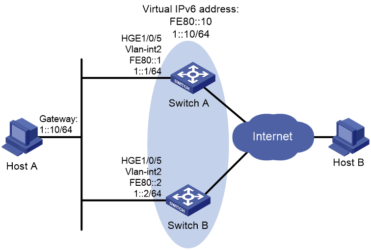
Configuration procedure
1. Configure Switch A:
# Configure VLAN 2.
<SwitchA> system-view
[SwitchA] vlan 2
[SwitchA-vlan2] port hundredgige 1/0/5
[SwitchA-vlan2] quit
[SwitchA] interface vlan-interface 2
[SwitchA-Vlan-interface2] ipv6 address fe80::1 link-local
[SwitchA-Vlan-interface2] ipv6 address 1::1 64
# Create VRRP group 1, and set its virtual IPv6 addresses to FE80::10 and 1::10.
[SwitchA-Vlan-interface2] vrrp ipv6 vrid 1 virtual-ip fe80::10 link-local
[SwitchA-Vlan-interface2] vrrp ipv6 vrid 1 virtual-ip 1::10
# Assign Switch A a higher priority than Switch B in VRRP group 1, so Switch A can become the master.
[SwitchA-Vlan-interface2] vrrp ipv6 vrid 1 priority 110
# Configure Switch A to operate in preemptive mode, so it can become the master whenever it operates correctly. Set the preemption delay to 5000 centiseconds to avoid frequent status switchover.
[SwitchA-Vlan-interface2] vrrp ipv6 vrid 1 preempt-mode delay 5000
# Enable Switch A to send RA messages, so Host A can learn the default gateway address.
[SwitchA-Vlan-interface2] undo ipv6 nd ra halt
2. Configure Switch B:
# Configure VLAN 2.
<SwitchB> system-view
[SwitchB] vlan 2
[SwitchB-vlan2] port hundredgige 1/0/5
[SwitchB-vlan2] quit
[SwitchB] interface vlan-interface 2
[SwitchB-Vlan-interface2] ipv6 address fe80::2 link-local
[SwitchB-Vlan-interface2] ipv6 address 1::2 64
# Create VRRP group 1 and set its virtual IPv6 addresses to FE80::10 and 1::10.
[SwitchB-Vlan-interface2] vrrp ipv6 vrid 1 virtual-ip fe80::10 link-local
[SwitchB-Vlan-interface2] vrrp ipv6 vrid 1 virtual-ip 1::10
# Configure Switch B to operate in preemptive mode, and set the preemption delay to 5000 centiseconds.
[SwitchB-Vlan-interface2] vrrp ipv6 vrid 1 preempt-mode delay 5000
# Enable Switch B to send RA messages, so Host A can learn the default gateway address.
[SwitchB-Vlan-interface2] undo ipv6 nd ra halt
Verifying the configuration
# Ping Host B from Host A. (Details not shown.)
# Display detailed information about VRRP group 1 on Switch A.
[SwitchA-Vlan-interface2] display vrrp ipv6 verbose
IPv6 Virtual Router Information:
Running Mode : Standard
Total number of virtual routers : 1
Interface Vlan-interface2
VRID : 1 Adver Timer : 100
Admin Status : Up State : Master
Config Pri : 110 Running Pri : 110
Preempt Mode : Yes Delay Time : 5000
Auth Type : None
Virtual IP : FE80::10
1::10
Virtual MAC : 0000-5e00-0201
Master IP : FE80::1
# Display detailed information about VRRP group 1 on Switch B.
[SwitchB-Vlan-interface2] display vrrp ipv6 verbose
IPv6 Virtual Router Information:
Running Mode : Standard
Total number of virtual routers : 1
Interface Vlan-interface2
VRID : 1 Adver Timer : 100
Admin Status : Up State : Backup
Config Pri : 100 Running Pri : 100
Preempt Mode : Yes Delay Time : 5000
Become Master : 403ms left
Auth Type : None
Virtual IP : FE80::10
1::10
Master IP : FE80::1
The output shows that Switch A is operating as the master in VRRP group 1 to forward packets from Host A to Host B.
# Disconnect the link between Host A and Switch A, and verify that Host A can still ping Host B. (Details not shown.)
# Display detailed information about VRRP group 1 on Switch B.
[SwitchB-Vlan-interface2] display vrrp ipv6 verbose
IPv6 Virtual Router Information:
Running Mode : Standard
Total number of virtual routers : 1
Interface Vlan-interface2
VRID : 1 Adver Timer : 100
Admin Status : Up State : Master
Config Pri : 100 Running Pri : 100
Preempt Mode : Yes Delay Time : 5000
Auth Type : None
Virtual IP : FE80::10
1::10
Virtual MAC : 0000-5e00-0201
Master IP : FE80::2
The output shows that when Switch A fails, Switch B takes over to forward packets from Host A to Host B.
# Recover the link between Host A and Switch A, and display detailed information about VRRP group 1 on Switch A.
[SwitchA-Vlan-interface2] display vrrp ipv6 verbose
IPv6 Virtual Router Information:
Running Mode : Standard
Total number of virtual routers : 1
Interface Vlan-interface2
VRID : 1 Adver Timer : 100
Admin Status : Up State : Master
Config Pri : 110 Running Pri : 110
Preempt Mode : Yes Delay Time : 5000
Auth Type : None
Virtual IP : FE80::10
1::10
Virtual MAC : 0000-5e00-0201
Master IP : FE80::1
The output shows that after Switch A resumes normal operation, it becomes the master to forward packets from Host A to Host B.
Multiple VRRP groups configuration example
Network requirements
As shown in Figure 35, Switch A and Switch B form two VRRP groups. VRRP group 1 uses the virtual IPv6 addresses 1::10/64 and FE80::10 to provide gateway service for hosts in VLAN 2. VRRP group 2 uses the virtual IPv6 addresses 2::10/64 and FE90::10 to provide gateway service for hosts in VLAN 3.
From RA messages sent by the switches, hosts in VLAN 2 learn 1::10/64 as their default gateway. Hosts in VLAN 3 learn 2::10/64 as their default gateway.
Assign Switch A a higher priority than Switch B in VRRP group 1 but a lower priority in VRRP group 2. Traffic from VLAN 2 and VLAN 3 can then be distributed between the two switches. When one of the switches fails, the healthy switch provides gateway service for both VLANs.
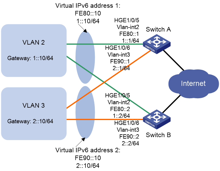
Configuration procedure
1. Configure Switch A:
# Configure VLAN 2.
<SwitchA> system-view
[SwitchA] vlan 2
[SwitchA-vlan2] port hundredgige 1/0/5
[SwitchA-vlan2] quit
[SwitchA] interface vlan-interface 2
[SwitchA-Vlan-interface2] ipv6 address fe80::1 link-local
[SwitchA-Vlan-interface2] ipv6 address 1::1 64
# Create VRRP group 1, and set its virtual IPv6 addresses to FE80::10 to 1::10.
[SwitchA-Vlan-interface2] vrrp ipv6 vrid 1 virtual-ip fe80::10 link-local
[SwitchA-Vlan-interface2] vrrp ipv6 vrid 1 virtual-ip 1::10
# Assign Switch A a higher priority than Switch B in VRRP group 1, so Switch A can become the master in the group.
[SwitchA-Vlan-interface2] vrrp ipv6 vrid 1 priority 110
# Enable Switch A to send RA messages, so hosts in VLAN 2 can learn the default gateway address.
[SwitchA-Vlan-interface2] undo ipv6 nd ra halt
[SwitchA-Vlan-interface2] quit
# Configure VLAN 3.
[SwitchA] vlan 3
[SwitchA-vlan3] port hundredgige 1/0/6
[SwitchA-vlan3] quit
[SwitchA] interface vlan-interface 3
[SwitchA-Vlan-interface3] ipv6 address fe90::1 link-local
[SwitchA-Vlan-interface3] ipv6 address 2::1 64
# Create VRRP group 2, and set its virtual IPv6 addresses to FE90::10 and 2::10.
[SwitchA-Vlan-interface3] vrrp ipv6 vrid 2 virtual-ip fe90::10 link-local
[SwitchA-Vlan-interface3] vrrp ipv6 vrid 2 virtual-ip 2::10
# Enable Switch A to send RA messages, so hosts in VLAN 3 can learn the default gateway address.
[SwitchA-Vlan-interface3] undo ipv6 nd ra halt
2. Configure Switch B:
# Configure VLAN 2.
<SwitchB> system-view
[SwitchB-vlan2] port hundredgige 1/0/5
[SwitchB-vlan2] quit
[SwitchB] interface vlan-interface 2
[SwitchB-Vlan-interface2] ipv6 address fe80::2 link-local
[SwitchB-Vlan-interface2] ipv6 address 1::2 64
# Create VRRP group 1, and set its virtual IPv6 addresses to FE80::10 and 1::10.
[SwitchB-Vlan-interface2] vrrp ipv6 vrid 1 virtual-ip fe80::10 link-local
[SwitchB-Vlan-interface2] vrrp ipv6 vrid 1 virtual-ip 1::10
# Enable Switch B to send RA messages, so hosts in VLAN 2 can learn the default gateway address.
[SwitchB-Vlan-interface2] undo ipv6 nd ra halt
[SwitchB-Vlan-interface2] quit
# Configure VLAN 3.
[SwitchB] vlan 3
[SwitchB-vlan3] port hundredgige 1/0/6
[SwitchB-vlan3] quit
[SwitchB] interface vlan-interface 3
[SwitchB-Vlan-interface3] ipv6 address fe90::2 link-local
[SwitchB-Vlan-interface3] ipv6 address 2::2 64
# Create VRRP group 2, and set its virtual IPv6 addresses to FE90::10 and 2::10.
[SwitchB-Vlan-interface3] vrrp ipv6 vrid 2 virtual-ip fe90::10 link-local
[SwitchB-Vlan-interface3] vrrp ipv6 vrid 2 virtual-ip 2::10
# Assign Switch B a higher priority than Switch A in VRRP group 2, so Switch B can become the master in the group.
[SwitchB-Vlan-interface3] vrrp ipv6 vrid 2 priority 110
# Enable Switch B to send RA messages, so hosts in VLAN 3 can learn the default gateway address.
[SwitchB-Vlan-interface3] undo ipv6 nd ra halt
Verifying the configuration
# Display detailed information about the VRRP groups on Switch A.
[SwitchA-Vlan-interface3] display vrrp ipv6 verbose
IPv6 Virtual Router Information:
Running Mode : Standard
Total number of virtual routers : 2
Interface Vlan-interface2
VRID : 1 Adver Timer : 100
Admin Status : Up State : Master
Config Pri : 110 Running Pri : 110
Preempt Mode : Yes Delay Time : 0
Auth Type : None
Virtual IP : FE80::10
1::10
Virtual MAC : 0000-5e00-0201
Master IP : FE80::1
Interface Vlan-interface3
VRID : 2 Adver Timer : 100
Admin Status : Up State : Backup
Config Pri : 100 Running Pri : 100
Preempt Mode : Yes Delay Time : 0
Become Master : 402ms left
Auth Type : None
Virtual IP : FE90::10
2::10
Master IP : FE90::2
# Display detailed information about the VRRP groups on Switch B.
[SwitchB-Vlan-interface3] display vrrp ipv6 verbose
IPv6 Virtual Router Information:
Running Mode : Standard
Total number of virtual routers : 2
Interface Vlan-interface2
VRID : 1 Adver Timer : 100
Admin Status : Up State : Backup
Config Pri : 100 Running Pri : 100
Preempt Mode : Yes Delay Time : 0
Become Master : 401ms left
Auth Type : None
Virtual IP : FE80::10
1::10
Master IP : FE80::1
Interface Vlan-interface3
VRID : 2 Adver Timer : 100
Admin Status : Up State : Master
Config Pri : 110 Running Pri : 110
Preempt Mode : Yes Delay Time : 0
Auth Type : None
Virtual IP : FE90::10
2::10
Virtual MAC : 0000-5e00-0202
Master IP : FE90::2
The output shows the following information:
· Switch A is operating as the master in VRRP group 1 to forward Internet traffic for hosts that use the default gateway 1::10/64.
· Switch B is operating as the master in VRRP group 2 to forward Internet traffic for hosts that use the default gateway 2::10/64.
VRRP load balancing configuration example
Network requirements
As shown in Figure 36, Switch A, Switch B, and Switch C form a load balanced VRRP group. They use the virtual IPv6 addresses FE80::10 and 1::10 to provide gateway service for subnet 1::/64.
Hosts on subnet 1::/64 learn 1::10 as their default gateway from RA messages sent by the switches.
Configure VFs on Switch A, Switch B, or Switch C to monitor their respective VLAN-interface 3. When the interface on any of them fails, the weights of the VFs on the problematic switch decrease so another AVF can take over.
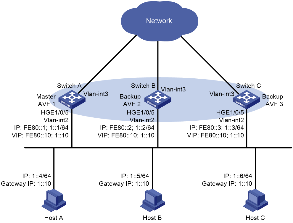
Configuration procedure
1. Configure Switch A:
# Configure VLAN 2.
<SwitchA> system-view
[SwitchA] vlan 2
[SwitchA-vlan2] port hundredgige 1/0/5
[SwitchA-vlan2] quit
# Configure VRRP to operate in load balancing mode.
[SwitchA] vrrp ipv6 mode load-balance
# Create VRRP group 1, and set its virtual IPv6 addresses to FE80::10 and 1::10.
[SwitchA] interface vlan-interface 2
[SwitchA-Vlan-interface2] ipv6 address fe80::1 link-local
[SwitchA-Vlan-interface2] ipv6 address 1::1 64
[SwitchA-Vlan-interface2] vrrp ipv6 vrid 1 virtual-ip fe80::10 link-local
[SwitchA-Vlan-interface2] vrrp ipv6 vrid 1 virtual-ip 1::10
# Assign Switch A the highest priority in VRRP group 1, so Switch A can become the master.
[SwitchA-Vlan-interface2] vrrp ipv6 vrid 1 priority 120
# Configure Switch A to operate in preemptive mode, so it can become the master whenever it operates correctly. Set the preemption delay to 5000 centiseconds to avoid frequent status switchover.
[SwitchA-Vlan-interface2] vrrp ipv6 vrid 1 preempt-mode delay 5000
# Enable Switch A to send RA messages, so hosts on subnet 1::/64 can learn the default gateway address.
[SwitchA-Vlan-interface2] undo ipv6 nd ra halt
[SwitchA-Vlan-interface2] quit
# Create track entry 1 to monitor the upstream link status of VLAN-interface 3. When the upstream link fails, the track entry transits to Negative.
[SwitchA] track 1 interface vlan-interface 3
# Configure the VFs in VRRP group 1 to monitor track entry 1, and decrease their weights by 250 when the track entry transits to Negative.
[SwitchA] interface vlan-interface 2
[SwitchA-Vlan-interface2] vrrp ipv6 vrid 1 track 1 weight reduced 250
2. Configure Switch B:
# Configure VLAN 2.
<SwitchB> system-view
[SwitchB] vlan 2
[SwitchB-vlan2] port hundredgige 1/0/5
[SwitchB-vlan2] quit
# Configure VRRP to operate in load balancing mode.
[SwitchB] vrrp ipv6 mode load-balance
# Create VRRP group 1, and set its virtual IPv6 addresses to FE80::10 and 1::10.
[SwitchB] interface vlan-interface 2
[SwitchB-Vlan-interface2] ipv6 address fe80::2 link-local
[SwitchB-Vlan-interface2] ipv6 address 1::2 64
[SwitchB-Vlan-interface2] vrrp ipv6 vrid 1 virtual-ip fe80::10 link-local
[SwitchB-Vlan-interface2] vrrp ipv6 vrid 1 virtual-ip 1::10
# Assign Switch B a higher priority than Switch C in VRRP group 1, so Switch B can become the master when Switch A fails.
[SwitchB-Vlan-interface2] vrrp ipv6 vrid 1 priority 110
# Configure Switch B to operate in preemptive mode, and set the preemption delay to 5000 centiseconds.
[SwitchB-Vlan-interface2] vrrp ipv6 vrid 1 preempt-mode delay 5000
# Enable Switch B to send RA messages so hosts on subnet 1::/64 can learn the default gateway address.
[SwitchB-Vlan-interface2] undo ipv6 nd ra halt
[SwitchB-Vlan-interface2] quit
# Create track entry 1 to monitor the upstream link status of VLAN-interface 3. When the upstream link fails, the track entry transits to Negative.
[SwitchB] track 1 interface vlan-interface 3
# Configure the VFs in VRRP group 1 to monitor track entry 1, and decrease their weights by 250 when the track entry transits to Negative.
[SwitchB] interface vlan-interface 2
[SwitchB-Vlan-interface2] vrrp ipv6 vrid 1 track 1 weight reduced 250
3. Configure Switch C:
# Configure VLAN 2.
<SwitchC> system-view
[SwitchC] vlan 2
[SwitchC-vlan2] port hundredgige 1/0/5
[SwitchC-vlan2] quit
# Configure VRRP to operate in load balancing mode.
[SwitchC] vrrp ipv6 mode load-balance
# Create VRRP group 1, and set its virtual IPv6 addresses to FE80::10 and 1::10.
[SwitchC] interface vlan-interface 2
[SwitchC-Vlan-interface2] ipv6 address fe80::3 link-local
[SwitchC-Vlan-interface2] ipv6 address 1::3 64
[SwitchC-Vlan-interface2] vrrp ipv6 vrid 1 virtual-ip fe80::10 link-local
[SwitchC-Vlan-interface2] vrrp ipv6 vrid 1 virtual-ip 1::10
# Configure Switch C to operate in preemptive mode, and set the preemption delay to 5000 centiseconds.
[SwitchC-Vlan-interface2] vrrp ipv6 vrid 1 preempt-mode delay 5000
# Enable Switch C to send RA messages, so the hosts on the subnet 1::/64 can learn the default gateway address.
[SwitchC-Vlan-interface2] undo ipv6 nd ra halt
[SwitchC-Vlan-interface2] quit
# Create track entry 1 to monitor the upstream link status of VLAN-interface 3. When the upstream link fails, the track entry transits to Negative.
[SwitchC] track 1 interface vlan-interface 3
# Configure the VFs in VRRP group 1 to monitor track entry 1, and decrease their weights by 250 when the track entry transits to Negative.
[SwitchC] interface vlan-interface 2
[SwitchC-Vlan-interface2] vrrp ipv6 vrid 1 track 1 weight reduced 250
Verifying the configuration
# Verify that Host A can ping the external network. (Details not shown.)
# Display detailed information about VRRP group 1 on Switch A.
[SwitchA-Vlan-interface2] display vrrp ipv6 verbose
IPv6 Virtual Router Information:
Running Mode : Load Balance
Total number of virtual routers : 1
Interface Vlan-interface2
VRID : 1 Adver Timer : 100
Admin Status : Up State : Master
Config Pri : 120 Running Pri : 120
Preempt Mode : Yes Delay Time : 5000
Auth Type : None
Virtual IP : FE80::10
1::10
Member IP List : FE80::1 (Local, Master)
FE80::2 (Backup)
FE80::3 (Backup)
Forwarder Information: 3 Forwarders 1 Active
Config Weight : 255
Running Weight : 255
Forwarder 01
State : Active
Virtual MAC : 000f-e2ff-4011 (Owner)
Owner ID : 0000-5e01-1101
Priority : 255
Active : local
Forwarder 02
State : Listening
Virtual MAC : 000f-e2ff-4012 (Learnt)
Owner ID : 0000-5e01-1103
Priority : 127
Active : FE80::2
Forwarder 03
State : Listening
Virtual MAC : 000f-e2ff-4013 (Learnt)
Owner ID : 0000-5e01-1105
Priority : 127
Active : FE80::3
Forwarder Weight Track Information:
Track Object : 1 State : Positive Weight Reduced : 250
# Display detailed information about VRRP group 1 on Switch B.
[SwitchB-Vlan-interface2] display vrrp ipv6 verbose
IPv6 Virtual Router Information:
Running Mode : Load Balance
Total number of virtual routers : 1
Interface Vlan-interface2
VRID : 1 Adver Timer : 100
Admin Status : Up State : Backup
Config Pri : 110 Running Pri : 110
Preempt Mode : Yes Delay Time : 5000
Become Master : 401ms left
Auth Type : None
Virtual IP : FE80::10
1::10
Member IP List : FE80::2 (Local, Backup)
FE80::1 (Master)
FE80::3 (Backup)
Forwarder Information: 3 Forwarders 1 Active
Config Weight : 255
Running Weight : 255
Forwarder 01
State : Listening
Virtual MAC : 000f-e2ff-4011 (Learnt)
Owner ID : 0000-5e01-1101
Priority : 127
Active : FE80::1
Forwarder 02
State : Active
Virtual MAC : 000f-e2ff-4012 (Owner)
Owner ID : 0000-5e01-1103
Priority : 255
Active : local
Forwarder 03
State : Listening
Virtual MAC : 000f-e2ff-4013 (Learnt)
Owner ID : 0000-5e01-1105
Priority : 127
Active : FE80::3
Forwarder Weight Track Information:
Track Object : 1 State : Positive Weight Reduced : 250
# Display detailed information about VRRP group 1 on Switch C.
[SwitchC-Vlan-interface2] display vrrp ipv6 verbose
IPv6 Virtual Router Information:
Running Mode : Load Balance
Total number of virtual routers : 1
Interface Vlan-interface2
VRID : 1 Adver Timer : 100
Admin Status : Up State : Backup
Config Pri : 100 Running Pri : 100
Preempt Mode : Yes Delay Time : 5000
Become Master : 402ms left
Auth Type : None
Virtual IP : FE80::10
1::10
Member IP List : FE80::3 (Local, Backup)
FE80::1 (Master)
FE80::2 (Backup)
Forwarder Information: 3 Forwarders 1 Active
Config Weight : 255
Running Weight : 255
Forwarder 01
State : Listening
Virtual MAC : 000f-e2ff-4011 (Learnt)
Owner ID : 0000-5e01-1101
Priority : 127
Active : FE80::1
Forwarder 02
State : Listening
Virtual MAC : 000f-e2ff-4012 (Learnt)
Owner ID : 0000-5e01-1103
Priority : 127
Active : FE80::2
Forwarder 03
State : Active
Virtual MAC : 000f-e2ff-4013 (Owner)
Owner ID : 0000-5e01-1105
Priority : 255
Active : local
Forwarder Weight Track Information:
Track Object : 1 State : Positive Weight Reduced : 250
The output shows that Switch A is the master in VRRP group 1, and each of the three switches has one AVF and two LVFs.
# Disconnect the link of VLAN-interface 3 on Switch A and display detailed information about VRRP group 1 on Switch A.
[SwitchA-Vlan-interface2] display vrrp ipv6 verbose
IPv6 Virtual Router Information:
Running Mode : Load Balance
Total number of virtual routers : 1
Interface Vlan-interface2
VRID : 1 Adver Timer : 100
Admin Status : Up State : Master
Config Pri : 120 Running Pri : 120
Preempt Mode : Yes Delay Time : 5000
Auth Type : None
Virtual IP : FE80::10
1::10
Member IP List : FE80::1 (Local, Master)
FE80::2 (Backup)
FE80::3 (Backup)
Forwarder Information: 3 Forwarders 0 Active
Config Weight : 255
Running Weight : 5
Forwarder 01
State : Initialize
Virtual MAC : 000f-e2ff-4011 (Owner)
Owner ID : 0000-5e01-1101
Priority : 0
Active : FE80::3
Forwarder 02
State : Initialize
Virtual MAC : 000f-e2ff-4012 (Learnt)
Owner ID : 0000-5e01-1103
Priority : 0
Active : FE80::2
Forwarder 03
State : Initialize
Virtual MAC : 000f-e2ff-4013 (Learnt)
Owner ID : 0000-5e01-1105
Priority : 0
Active : FE80::3
Forwarder Weight Track Information:
Track Object : 1 State : Negative Weight Reduced : 250
# Display detailed information about VRRP group 1 on Switch C.
[SwitchC-Vlan-interface2] display vrrp ipv6 verbose
IPv6 Virtual Router Information:
Running Mode : Load Balance
Total number of virtual routers : 1
Interface Vlan-interface2
VRID : 1 Adver Timer : 100
Admin Status : Up State : Backup
Config Pri : 100 Running Pri : 100
Preempt Mode : Yes Delay Time : 5000
Become Master : 410ms left
Auth Type : None
Virtual IP : FE80::10
1::10
Member IP List : FE80::3 (Local, Backup)
FE80::1 (Master)
FE80::2 (Backup)
Forwarder Information: 3 Forwarders 2 Active
Config Weight : 255
Running Weight : 255
Forwarder 01
State : Active
Virtual MAC : 000f-e2ff-4011 (Take Over)
Owner ID : 0000-5e01-1101
Priority : 85
Active : local
Forwarder 02
State : Listening
Virtual MAC : 000f-e2ff-4012 (Learnt)
Owner ID : 0000-5e01-1103
Priority : 85
Active : FE80::2
Forwarder 03
State : Active
Virtual MAC : 000f-e2ff-4013 (Owner)
Owner ID : 0000-5e01-1105
Priority : 255
Active : local
Forwarder Weight Track Information:
Track Object : 1 State : Positive Weight Reduced : 250
The output shows that when VLAN-interface 3 on Switch A fails, the weights of the VFs on Switch A drop below the lower limit of failure. All VFs on Switch A transit to the Initialized state and cannot forward traffic. The VF for MAC address 000f-e2ff-4011 on Switch C becomes the AVF to forward traffic.
# When the timeout timer (about 1800 seconds) expires, display detailed information about VRRP group 1 on Switch C.
[SwitchC-Vlan-interface2] display vrrp ipv6 verbose
IPv6 Virtual Router Information:
Running Mode : Load Balance
Total number of virtual routers : 1
Interface Vlan-interface2
VRID : 1 Adver Timer : 100
Admin Status : Up State : Backup
Config Pri : 100 Running Pri : 100
Preempt Mode : Yes Delay Time : 5000
Become Master : 400ms left
Auth Type : None
Virtual IP : FE80::10
1::10
Member IP List : FE80::3 (Local, Backup)
FE80::1 (Master)
FE80::2 (Backup)
Forwarder Information: 2 Forwarders 1 Active
Config Weight : 255
Running Weight : 255
Forwarder 02
State : Listening
Virtual MAC : 000f-e2ff-4012 (Learnt)
Owner ID : 0000-5e01-1103
Priority : 127
Active : FE80::2
Forwarder 03
State : Active
Virtual MAC : 000f-e2ff-4013 (Owner)
Owner ID : 0000-5e01-1105
Priority : 255
Active : local
Forwarder Weight Track Information:
Track Object : 1 State : Positive Weight Reduced : 250
The output shows that when the timeout timer expires, the VF for virtual MAC address 000f-e2ff-4011 is removed. The VF no longer forwards the packets destined for the MAC address.
# When Switch A fails, display detailed information about VRRP group 1 on Switch B.
[SwitchB-Vlan-interface2] display vrrp ipv6 verbose
IPv6 Virtual Router Information:
Running Mode : Load Balance
Total number of virtual routers : 1
Interface Vlan-interface2
VRID : 1 Adver Timer : 100
Admin Status : Up State : Master
Config Pri : 110 Running Pri : 110
Preempt Mode : Yes Delay Time : 5000
Auth Type : None
Virtual IP : FE80::10
1::10
Member IP List : FE80::2 (Local, Master)
FE80::3 (Backup)
Forwarder Information: 2 Forwarders 1 Active
Config Weight : 255
Running Weight : 255
Forwarder 02
State : Active
Virtual MAC : 000f-e2ff-4012 (Owner)
Owner ID : 0000-5e01-1103
Priority : 255
Active : local
Forwarder 03
State : Listening
Virtual MAC : 000f-e2ff-4013 (Learnt)
Owner ID : 0000-5e01-1105
Priority : 127
Active : FE80::3
Forwarder Weight Track Information:
Track Object : 1 State : Positive Weight Reduced : 250
The output shows the following information:
· When Switch A fails, Switch B becomes the master because it has a higher priority than Switch C.
· The VF for virtual MAC address 000f-e2ff-4011 is removed.
Troubleshooting VRRP
An error prompt is displayed
Symptom
An error prompt "The virtual router detected a VRRP configuration error." is displayed during configuration.
Analysis
This symptom is probably caused by the following reasons:
· The VRRP advertisement interval in the packet is not the same as that for the current VRRP group (in VRRPv2 only).
· The number of virtual IP addresses in the packet is not the same as that for the current VRRP group.
· The virtual IP address list is not the same as that for the current VRRP group.
· A device in the VRRP group receives illegitimate VRRP packets. For example, the IP address owner receives a VRRP packet with the priority 255.
Solution
To resolve the problem:
1. Modify the configuration on routers in VRRP groups to ensure consistent configuration.
2. Take fault location and anti-attack measures to eliminate potential threats.
3. If the problem persists, contact H3C Support.
Multiple masters appear in a VRRP group
Symptom
Multiple masters appear in a VRRP group.
Analysis
It is normal for a VRRP group to have multiple masters for a short time, and this situation requires no manual intervention.
If multiple masters coexist for a longer period, check for the following conditions:
· The masters cannot receive advertisements from each other.
· The received advertisements are illegitimate.
Solution
To resolve the problem:
1. Ping between these masters:
¡ If the ping operation fails, examine network connectivity.
¡ If the ping operation succeeds, check for configuration inconsistencies in the number of virtual IP addresses, virtual IP addresses, and authentication. For IPv4 VRRP, also make sure the same version of VRRP is configured on all routers in the VRRP group. For VRRPv2, make sure the same VRRP advertisement interval is configured on the routers in the VRRP group.
2. If the problem persists, contact H3C Support.
Fast VRRP state flapping
Symptom
Fast VRRP state flapping occurs.
Analysis
The VRRP advertisement interval is set too short.
Solution
To resolve the problem:
1. Increase the interval for sending VRRP advertisements or introduce a preemption delay.
2. If the problem persists, contact H3C Support.
Configuring BFD
Overview
Bidirectional forwarding detection (BFD) provides a general-purpose, standard, medium- and protocol-independent fast failure detection mechanism. It can detect and monitor the connectivity of links in IP to detect communication failures quickly so that measures can be taken to ensure service continuity and enhance network availability.
BFD can uniformly and quickly detect the failures of the bidirectional forwarding paths between two devices for upper-layer protocols such as routing protocols. The hello mechanism used by upper-layer protocols needs seconds to detect a link failure, while BFD can provide detection measured in milliseconds.
BFD can be used for single-hop and multihop detections.
· Single-hop detection—Detects the IP connectivity between two directly connected systems.
· Multihop detection—Detects any of the paths between two systems. These paths have multiple hops, and might overlap.
BFD session establishment and termination
Establishing a BFD session
BFD does not provide any neighbor discovery mechanisms. The upper protocol notifies BFD of the routers to which it needs to establish sessions.
A BFD session is established as follows:
1. A protocol sends Hello messages to discover neighbors and establish neighborships.
2. After establishing a neighborship, the protocol notifies BFD of the neighbor information, including destination and source addresses.
3. BFD uses the information to establish a BFD session.
Terminating a BFD session
When BFD detects a link failure, it performs the following tasks:
1. BFD clears the neighbor session.
2. BFD notifies the protocol of the failure.
3. The protocol terminates the neighborship on the link.
4. If a backup link is available, the protocol will use it for communication.
BFD session modes and operating modes
BFD sessions use the following types of packets:
· Echo packets—Encapsulated into UDP packets with port number 3785.
· Control packets—Encapsulated into UDP packets with port number 3784 for single-hop detection or port number 4784 for multihop detection.
Echo packet mode
The local end of the link sends echo packets to establish BFD sessions and monitor link status. The peer end does not establish BFD sessions and only forwards the packets back to the originating end.
In echo packet mode, BFD supports only single-hop detection and the BFD session is independent of the operating mode.
Control packet mode
Both ends of the link exchange BFD control packets to monitor link status.
Before a BFD session is established, BFD has two operating modes—active and passive.
· Active mode—BFD actively sends BFD control packets regardless of whether any BFD control packet is received from the peer.
· Passive mode—BFD does not send control packets until a BFD control packet is received from the peer.
At least one end must operate in active mode for a BFD session to be established.
After a BFD session is established, the two ends can operate in the following BFD operating modes:
· Asynchronous mode—The device periodically sends BFD control packets. The device considers that the session is down if it does not receive any BFD control packets within a specific interval.
· Demand mode—The device periodically sends BFD control packets. If the peer end is operating in Asynchronous mode (default), the peer end stops sending BFD control packets. If the peer end is operating in Demand mode, both ends stop sending BFD control packets. When the connectivity to another system needs to be verified explicitly, a system sends several BFD control packets with the Poll (P) bit set at the negotiated transmit interval. If no response is received within the detection interval, the session is considered down. If the connectivity is found to be up, no more BFD control packets are sent until the next command is issued.
In addition, both ends of the link can exchange BFD control packets to establish and maintain BFD sessions, and one end of the link sends echo packets to monitor link status.
Supported features
· Static routing. For more information, see Layer 3—IP Routing Configuration Guide.
· IPv6 static routing. For more information, see Layer 3—IP Routing Configuration Guide.
· RIP. For more information, see Layer 3—IP Routing Configuration Guide.
· OSPF. For more information, see Layer 3—IP Routing Configuration Guide.
· OSPFv3. For more information, see Layer 3—IP Routing Configuration Guide.
· IS-IS. For more information, see Layer 3—IP Routing Configuration Guide.
· IPv6 IS-IS. For more information, see Layer 3—IP Routing Configuration Guide.
· BGP. For more information, see Layer 3—IP Routing Configuration Guide.
· IPv6 BGP. For more information, see Layer 3—IP Routing Configuration Guide.
· PIM. For more information, see IP Multicast Configuration Guide.
· Track. For more information, see "Configuring Track."
· IP fast reroute (FRR). IP FRR is supported by BGP, OSPF, RIP, IS-IS, and static routing. For more information, see Layer 3—IP Routing Configuration Guide.
· Ethernet link aggregation. For more information, see Layer 2—LAN Switching Configuration Guide.
Protocols and standards
· RFC 5880, Bidirectional Forwarding Detection (BFD)
· RFC 5881, Bidirectional Forwarding Detection (BFD) for IPv4 and IPv6 (Single Hop)
· RFC 5882, Generic Application of Bidirectional Forwarding Detection (BFD)
· RFC 5883, Bidirectional Forwarding Detection (BFD) for Multihop Paths
· RFC 7130, Bidirectional Forwarding Detection (BFD) on Link Aggregation Group (LAG) Interfaces
Configuring BFD basic functions
Before configuring BFD basic functions, configure the network layer addresses of the interfaces so that adjacent nodes are reachable to each other at the network layer.
After a BFD session is established, the two ends negotiate BFD parameters, including minimum sending interval, minimum receiving interval, initialization mode, and packet authentication, by exchanging negotiation packets. They use the negotiated parameters without affecting the session status.
BFD session flapping might occur on an aggregate interface with member ports on different cards. When the card that receives and sends BFD packets is removed or restarted, the backup card might not immediately take over. For example, the backup card will not take over when the card has a short detection time or a large number of BFD sessions.
By default, the device runs BFD version 1 and is compatible with BFD version 0. You cannot change the BFD version to 0 through commands. When the peer device runs BFD version 0, the local device automatically switches to BFD version 0.
Configuring echo packet mode
|
|
CAUTION: To avoid echo packet loss, do not configure the echo packet mode on a device with uRPF enabled. For more information about uRPF, see Security Configuration Guide. |
To configure echo packet mode:
|
Step |
Command |
Remarks |
|
1. Enter system view. |
system-view |
N/A |
|
2. Configure the source IP address of echo packets. |
· Configure the source IP address of echo
packets: · Configure the source IPv6 address of echo
packets: |
By default, no source IP address is configured for echo packets. The source IP address cannot be on the same network segment as any local interfaces. Otherwise, a large number of ICMP redirect packets might be sent from the peer, resulting in link congestion. To avoid echo packet loss, do not enable sending of ICMP redirect packets on the peer end. The source IPv6 address of echo packets can only be a global unicast address. |
|
3. Enter interface view. |
interface interface-type interface-number |
N/A |
|
4. (Optional.) Set the minimum interval for receiving BFD echo packets. |
bfd min-echo-receive-interval interval |
By default, the minimum interval for receiving BFD echo packets is 400 milliseconds. |
|
5. (Optional.) Set the single-hop detection time multiplier. |
bfd detect-multiplier value |
The default setting is 5. |
Configuring control packet mode
To configure control packet mode for single-hop detection:
|
Step |
Command |
Remarks |
|
1. Enter system view. |
system-view |
N/A |
|
2. Specify the mode for establishing a BFD session. |
bfd session init-mode { active | passive } |
By default, active is specified. BFD version 0 does not support this command. The configuration does not take effect. |
|
3. Enter interface view. |
interface interface-type interface-number |
N/A |
|
4. Configure the authentication mode for single-hop control packets. |
bfd authentication-mode { m-md5 | m-sha1 | md5 | sha1 | simple } key-id { cipher cipher-string | plain plain-string } |
By default, single-hop BFD packets are not authenticated. BFD version 0 does not support this command. The configuration does not take effect. |
|
5. Enable the Demand BFD session mode. |
bfd demand enable |
By default, the BFD session is in Asynchronous mode. BFD version 0 does not support this command. The configuration does not take effect. |
|
6. Enable the echo packet mode. |
bfd echo [ receive | send ] enable |
By default, the echo packet mode is disabled. BFD version 0 does not support this command. The configuration does not take effect. Configure this command for BFD sessions in which control packets are sent. When you enable the echo packet mode for such a session in up state, BFD periodically sends echo packets to detect link connectivity and decrease control packet receive rate. |
|
7. Set the minimum interval for transmitting single-hop BFD control packets. |
bfd min-transmit-interval interval |
By default, the minimum interval for transmitting single-hop BFD control packets is 400 milliseconds. |
|
8. Set the minimum interval for receiving single-hop BFD control packets. |
bfd min-receive-interval interval |
By default, the minimum interval for receiving single-hop BFD control packets is 400 milliseconds. |
|
9. Set the single-hop detection time multiplier. |
bfd detect-multiplier value |
The default setting is 5. |
|
10. Create a BFD session for detecting the local interface state. |
bfd detect-interface source-ip ip-address |
By default, no BFD session is created for detecting the local interface state. |
To configure control packet mode for multihop detection:
|
Step |
Command |
Remarks |
|
1. Enter system view. |
system-view |
N/A |
|
2. Specify the mode for establishing a BFD session. |
bfd session init-mode { active | passive } |
By default, active is specified. BFD version 0 does not support this command. The configuration does not take effect. |
|
3. Configure the authentication mode for multihop BFD control packets. |
bfd multi-hop authentication-mode { m-md5 | m-sha1 | md5 | sha1 | simple } key-id { cipher cipher-string | plain plain-string } |
By default, no authentication is performed. BFD version 0 does not support this command. The configuration does not take effect. |
|
4. Configure the destination port number for multihop BFD control packets. |
bfd multi-hop destination-port port-number |
The default setting is 4784. |
|
5. Set the multihop detection time multiplier. |
bfd multi-hop detect-multiplier value |
The default setting is 5. |
|
6. Set the minimum interval for receiving multihop BFD control packets. |
bfd multi-hop min-receive-interval interval |
By default, the minimum interval for receiving multihop BFD control packets is 400 milliseconds. |
|
7. Set the minimum interval for transmitting multihop BFD control packets. |
bfd multi-hop min-transmit-interval interval |
By default, the minimum interval for transmitting multihop BFD control packets is 400 milliseconds. |
Enabling SNMP notifications for BFD
To report critical BFD events to an NMS, enable SNMP notifications for BFD. For BFD event notifications to be sent correctly, you must also configure SNMP as described in Network Management and Monitoring Configuration Guide.
To enable SNMP notifications for BFD:
|
Command |
Remarks |
|
|
1. Enter system view. |
system-view |
N/A |
|
2. Enable SNMP notifications for BFD. |
snmp-agent trap enable bfd |
By default, SNMP notifications are enabled for BFD. |
Displaying and maintaining BFD
Execute the display command in any view and the reset command in user view.
|
Task |
Command |
|
Display BFD session information. |
display bfd session [ discriminator value | verbose ] |
|
Clear BFD session statistics. |
reset bfd session statistics |
Configuring Track
Overview
Collaboration is enabled when you associate the Track module with a detection module and an application module, and it operates as follows:
1. The detection module probes specific objects such as interface status, link status, network reachability, and network performance, and informs the Track module of detection results.
2. The Track module sends the detection results to the application module.
3. When notified of changes for the tracked object, the application modules can react to avoid communication interruption and network performance degradation.
Collaboration fundamentals
The Track module collaborates with detection modules and application modules.
Collaboration between the Track module and a detection module
The detection module sends the detection result of the tracked object to the Track module. The Track module changes the status of the track entry as follows:
· If the tracked object operates correctly, the state of the track entry is Positive. For example, the track entry state is Positive in one of the following conditions:
¡ The target interface is up.
¡ The target network is reachable.
· If the tracked object does not operate correctly, the state of the track entry is Negative. For example, the track entry state is Negative in one of the following conditions:
¡ The target interface is down.
¡ The target network is unreachable.
· If the detection result is invalid, the state of the track entry is NotReady. For example, the track entry state is NotReady if its associated NQA operation does not exist.
The following detection modules can be associated with the Track module:
· NQA.
· BFD.
· Interface management.
· Route management.
Collaboration between the Track module and an application module
The following application modules can be associated with the Track module:
· VRRP.
· Static routing.
· PBR.
· VXLAN.
· EAA.
When configuring a track entry for an application module, you can set a notification delay to avoid immediate notification of status changes.
When the delay is not configured and the route convergence is slower than the link state change notification, communication failures occur. For example, when the master in a VRRP group detects an uplink interface failure through Track, Track immediately notifies the master to decrease its priority. A backup with a higher priority then preempts as the new master. When the failed uplink interface recovers, the Track module immediately notifies the original master to restore its priority. If the uplink route has not recovered, forwarding failure will occur.
Collaboration application example
The following is an example of collaboration between NQA, Track, and static routing.
Configure a static route with the next hop 192.168.0.88 on the device. If the next hop is reachable, the static route is valid. If the next hop becomes unreachable, the static route is invalid. For this purpose, configure NQA-Track-static routing collaboration as follows:
1. Create an NQA operation to monitor the accessibility of IP address 192.168.0.88.
2. Create a track entry and associate it with the NQA operation.
¡ When the next hop 192.168.0.88 is reachable, NQA sends the result to the Track module. The Track module sets the track entry to Positive state.
¡ When the next hop becomes unreachable, NQA sends the result to the Track module. The Track module sets the track entry to Negative state.
3. Associate the track entry with the static route.
¡ When the track entry is in Positive state, the static routing module considers the static route to be valid.
¡ When the track entry is in Negative state, the static routing module considers the static route to be invalid.
Track configuration task list
To implement the collaboration function, establish associations between the Track module and detection modules, and between the Track module and application modules.
To configure the Track module, perform the following tasks:
|
Tasks at a glance |
|
(Required.) Associating the Track module with a detection module |
|
(Required.) Associating the Track module with an application module: · Associating Track with static routing |
Associating the Track module with a detection module
Associating Track with NQA
NQA supports multiple operation types to analyze network performance and service quality. For example, an NQA operation can periodically detect whether a destination is reachable, or whether a TCP connection can be established.
An NQA operation operates as follows when it is associated with a track entry:
· If the consecutive failures reach the specified threshold, the NQA module notifies the Track module that the tracked object has malfunctioned. The Track module then sets the track entry to Negative state.
· If the specified threshold is not reached, the NQA module notifies the Track module that the tracked object is operating correctly. The Track module then sets the track entry to Positive state.
For more information about NQA, see Network Management and Monitoring Configuration Guide.
To associate Track with NQA:
|
Step |
Command |
Remarks |
|
1. Enter system view. |
system-view |
N/A |
|
2. Create a track entry, and associate it with an NQA reaction entry. |
track track-entry-number nqa entry admin-name operation-tag reaction item-number [ delay { negative negative-time | positive positive-time } * ] |
By default, no track entries exist. If the specified NQA operation or the reaction entry in the track entry does not exist, the status of the track entry is NotReady. |
Associating Track with BFD
BFD supports the control packet mode and echo packet mode. A track entry can be associated only with the echo-mode BFD session. For more information about BFD, see "Configuring BFD."
The associated Track and BFD operate as follows:
· If the BFD detects that the link fails, it informs the Track module of the link failure. The Track module sets the track entry to Negative state.
· If the BFD detects that the link is operating correctly, the Track module sets the track entry to Positive state.
Before you associate Track with BFD, configure the source IP address of BFD echo packets. For more information, see "Configuring BFD."
To associate Track with BFD:
|
Step |
Command |
Remarks |
|
1. Enter system view. |
system-view |
N/A |
|
2. Create a track entry, and associate it with a BFD session. |
track track-entry-number bfd echo interface interface-type interface-number remote ip remote-ip-address local ip local-ip-address [ delay { negative negative-time | positive positive-time } * ] |
By default, no track entries exist. Do not configure the virtual IP address of a VRRP group as the local or remote address of a BFD session. |
Associating Track with interface management
The interface management module monitors the link status or network-layer protocol status of interfaces. The associated Track and interface management operate as follows:
· When the link or network-layer protocol status of the interface changes to up, the interface management module informs the Track module of the change. The Track module sets the track entry to Positive state.
· When the link or network-layer protocol status of the interface changes to down, the interface management module informs the Track module of the change. The Track module sets the track entry to Negative state.
To associate Track with interface management:
|
Step |
Command |
Remarks |
|
1. Enter system view. |
system-view |
N/A |
|
2. Create a track entry, and associate it with interface management. |
· Create a track entry, and associate it with
the interface management module to monitor the link status of an interface: · Create a track entry, and associate it with the
interface management module to monitor the physical status of an interface: · Create a track entry, and associate it with
the interface management module to monitor the network-layer protocol status
of an interface: |
By default, no track entries exist. |
Associating Track with route management
The route management module monitors route entry changes in the routing table. The associated Track and route management operate as follows:
· When a monitored route entry is found in the routing table, the route management module informs the Track module. The Track module sets the track entry to Positive state.
· When a monitored route entry is removed from the routing table, the route management module informs the Track module of the change. The Track module sets the track entry to Negative state.
To associate Track with route management:
|
Step |
Command |
Remarks |
|
1. Enter system view. |
system-view |
N/A |
|
2. Create a track entry and associate it with a route entry. |
track track-entry-number ip route [ vpn-instance vpn-instance-name ] ip-address { mask-length | mask } reachability [ delay { negative negative-time | positive positive-time } * ] |
By default, no track entries exist. |
Associating the Track module with an application module
Before you associate the Track module with an application module, make sure the associated track entry has been created.
Associating Track with VRRP
When VRRP is operating in standard mode or load balancing mode, associate the Track module with the VRRP group to implement the following actions:
· Change the priority of a router according to the status of the uplink. If a fault occurs on the uplink of the router, the VRRP group is not aware of the uplink failure. If the router is the master, hosts in the LAN cannot access the external network. To resolve this problem, configure a detection module-Track-VRRP collaboration. The detection module monitors the status of the uplink of the router and notifies the Track module of the detection result.
When the uplink fails, the detection module notifies the Track module to change the status of the monitored track entry to Negative. The priority of the master decreases by a user-specified value. A router with a higher priority in the VRRP group becomes the master.
· Monitor the master on a backup. If a fault occurs on the master, the backup operating in switchover mode will switch to the master immediately to maintain normal communication.
When VRRP is operating in load balancing mode, associate the Track module with the VRRP VF to implement the following functions:
· Change the priority of the AVF according to its uplink state. When the uplink of the AVF fails, the track entry changes to Negative state. The weight of the AVF decreases by a user-specified value. The VF with a higher priority becomes the new AVF to forward packets.
· Monitor the AVF status from the LVF. When the AVF fails, the LVF that is operating in switchover mode becomes the new AVF to ensure continuous forwarding.
When you associate Track with VRRP, follow these restrictions and guidelines:
· VRRP tracking does not take effect on an IP address owner. The configuration takes effect when the router does not act as the IP address owner.
An IP address owner is the router with its interface IP address used as the virtual IP address of the VRRP group.
· When the status of the track entry changes from Negative to Positive or NotReady, the associated router or VF restores its priority automatically.
Associating Track with a VRRP group
|
Step |
Command |
Remarks |
|
1. Enter system view. |
system-view |
N/A |
|
2. Enter interface view. |
interface interface-type interface-number |
N/A |
|
3. Associate a track entry with a VRRP group. |
vrrp [ ipv6 ] vrid virtual-router-id track track-entry-number { forwarder-switchover member-ip ip-address | priority reduced [ priority-reduced ] switchover | weight reduced [ weight-reduced ] } |
By default, no track entry is specified for a VRRP group. This command is supported when VRRP is operating in both standard mode and load balancing mode. |
Associating Track with a VRRP VF
|
Step |
Command |
Remarks |
|
1. Enter system view. |
system-view |
N/A |
|
2. Enter interface view. |
interface interface-type interface-number |
N/A |
|
3. Associate Track with a VRRP VF. |
vrrp [ ipv6 ] vrid virtual-router-id track track-entry-number { forwarder-switchover member-ip ip-address | priority reduced [ priority-reduced ] switchover | weight reduced [ weight-reduced ] } |
By default, no track entry is specified for a VF. This command is configurable when VRRP is operating in standard mode or load balancing mode. However, this command takes effect only when VRRP is operating in load balancing mode. |
Associating Track with static routing
A static route is a manually configured route to route packets. For more information about static route configuration, see Layer 3—IP Routing Configuration Guide.
Static routes cannot adapt to network topology changes. Link failures or network topological changes can make the routes unreachable and cause communication interruption.
To resolve this problem, configure another route to back up the static route. When the static route is reachable, packets are forwarded through the static route. When the static route is unreachable, packets are forwarded through the backup route.
To check the accessibility of a static route in real time, associate the Track module with the static route.
If you specify the next hop but not the output interface when configuring a static route, you can configure the static routing-Track-detection module collaboration. This collaboration enables you to verify the accessibility of the static route based on the track entry state.
· If the track entry is in Positive state, the following conditions exist:
¡ The next hop of the static route is reachable.
¡ The configured static route is valid.
· If the track entry is in Negative state, the following conditions exist:
¡ The next hop of the static route is not reachable.
¡ The configured static route is invalid.
· If the track entry is in NotReady state, the following conditions exist:
¡ The accessibility of the next hop of the static route is unknown.
¡ The static route is valid.
When you associate Track with static routing, follow these restrictions and guidelines:
· In static routing-Track-NQA collaboration, you must configure the same VPN instance name for the NQA operation and the next hop of the static route. Otherwise, the accessibility detection cannot operate correctly.
· If a static route needs route recursion, the associated track entry must monitor the next hop of the recursive route. The next hop of the static route cannot be monitored. Otherwise, a valid route might be considered invalid.
To associate Track with static routing:
|
Step |
Command |
Remarks |
|
1. Enter system view. |
system-view |
N/A |
|
2. Associate a static route with a track entry to check the accessibility of the next hop. |
· Method 1: · Method 2: |
By default, Track is not associated with static routing. |
Associating Track with PBR
PBR uses user-defined policies to route packets. You can specify parameters to guide the forwarding of the packets that match specific criteria. The parameters include the next hop and the default next hop. For more information about PBR, see Layer 3—IP Routing Configuration Guide.
PBR cannot detect the availability of any action taken on packets. When an action is not available, packets processed by the action might be discarded. For example, if the next hop specified for PBR fails, PBR cannot detect the failure, and continues to forward matching packets to the next hop.
To enable PBR to detect topology changes and improve the flexibility of the PBR application, configure Track-PBR-detection module collaboration.
After you associate a track entry with an apply clause, the detection module associated with the track entry sends Track the detection result of the availability of the tracked object.
· The Positive state of the track entry indicates that the object is available, and the apply clause is valid.
· The Negative state of the track entry indicates that the object is not available, and the apply clause is invalid.
· The NotReady state of the track entry indicates that the apply clause is valid.
The following objects can be associated with a track entry:
· Next hop.
· Default next hop.
Configuration prerequisites
Before you associate Track with PBR, create a node for a policy, and configure the match criteria.
Configuration procedure
To associate Track with PBR:
|
Step |
Command |
Remarks |
|
1. Enter system view. |
system-view |
N/A |
|
2. Create a node for a policy and enter its view. |
policy-based-route policy-name [ deny | permit ] node node-number |
N/A |
|
3. Set a match criterion. |
· Set an ACL match criterion: · Set a VXLAN match criterion: |
By default, no match criterion exists. |
|
4. Associate Track with PBR. |
· Set the next hop, and associate it with a
track entry: · Set the default next hop, and associate it
with a track entry: |
Use a minimum of one command. |
To associate Track with IPv6 PBR:
|
Step |
Command |
Remarks |
|
1. Enter system view. |
system-view |
N/A |
|
2. Create a node for a policy and enter its view. |
ipv6 policy-based-route policy-name [ deny | permit ] node node-number |
N/A |
|
3. Set an ACL match criterion. |
if-match acl { ipv6-acl-number | name ipv6-acl-name } |
By default, no ACL match criterion exists. |
|
4. Associate Track with IPv6 PBR. |
· Set the next hop, and associate it with a
track entry: · Set the default next hop, and associate it
with a track entry: |
Use a minimum of one command. |
Associating Track with VXLAN
The AC can be one of the following types:
· Layer 3 interface.
· Ethernet service instance on a Layer 2 Ethernet interface or Layer 2 aggregate interface.
To associate a Layer 3 interface with a track entry:
|
Step |
Command |
Remarks |
|
1. Enter system view. |
system-view |
N/A |
|
2. Enter Layer 3 interface view. |
interface interface-type interface-number |
N/A |
|
3. Bind the interface to a VSI and associate it with a track entry. |
xconnect vsi vsi-name track track-entry-number&<1-3> |
By default, the interface is not bound to any VSI or associated with any track entry. |
To associate an Ethernet service instance with a track entry:
|
Step |
Command |
Remarks |
|
1. Enter system view. |
system-view |
N/A |
|
2. Enter Layer 2 Ethernet interface view or Layer 2 aggregate interface view. |
· Enter Layer 2 Ethernet interface view: · Enter Layer 2 aggregate interface view: |
N/A |
|
3. Create an Ethernet service instance and enter its view. |
service-instance instance-id |
By default, no Ethernet service instances exist. |
|
4. Bind the Ethernet service instance to a VSI and associate it with a track entry. |
xconnect vsi vsi-name [ access-mode { ethernet | vlan } ] * track track-entry-number&<1-3> |
By default, an Ethernet service instance is not bound to any VSI or associated with any track entry. |
Associating Track with EAA
Embedded Automation Architecture (EAA) is a monitoring framework that enables you to self-define monitored events and the actions to take. It allows you to create monitor policies by using the CLI or Tcl scripts.
For more information about EAA, see Network Management and Monitoring Configuration Guide.
You can configure EAA track event monitor policies to monitor the positive-to-negative or negative-to-positive state changes of track entries.
· If you specify only one track entry for a policy, EAA triggers the policy when it detects the specified state change on the track entry.
· If you specify multiple track entries for a policy, EAA triggers the policy when it detects the specified state change on the last monitored track entry. For example, if you configure a policy to monitor the positive-to-negative state change of multiple track entries, EAA triggers the policy when the last positive track entry monitored by the policy changes to the Negative state.
You can set a suppression time for a track event monitor policy. The timer starts when the policy is triggered. The system does not process messages that report the monitored track event until the timer times out.
To configure a track event monitor policy:
|
Step |
Command |
Remarks |
|
1. Enter system view. |
system-view |
N/A |
|
2. Create a CLI-defined monitor policy and enter its view, or enter the view of an existing CLI-defined monitor policy. |
rtm cli-policy policy-name |
By default, no CLI-defined monitor policies exist. |
|
3. Configure a track event. |
event track track-entry-number-list state { negative | positive } [ suppress-time suppress-time ] |
By default, a monitor policy does not monitor any track event. |
Displaying and maintaining track entries
Execute display commands in any view.
|
Task |
Command |
|
Display information about track entries. |
display track { track-entry-number | all [ negative | positive ] } [ brief ] |
Track configuration examples
VRRP-Track-NQA collaboration configuration example
Network requirements
As shown in Figure 37:
· Host A requires access to Host B. The default gateway of Host A is 10.1.1.10/24.
· Switch A and Switch B belong to VRRP group 1. The virtual IP address of VRRP group 1 is 10.1.1.10.
Configure VRRP-Track-NQA collaboration to monitor the uplink on the master and meet the following requirements:
· When Switch A operates correctly, Switch A forwards packets from Host A to Host B.
· When NQA detects a fault on the uplink of Switch A, Switch B forwards packets from Host A to Host B.

Configuration procedure
1. Create VLANs and assign ports to them. Configure the IP address of each VLAN interface, as shown in Figure 37. (Details not shown.)
2. Configure an NQA operation on Switch A:
# Create an NQA operation with administrator name admin and operation tag test.
<SwitchA> system-view
[SwitchA] nqa entry admin test
# Configure the operation type as ICMP echo.
[SwitchA-nqa-admin-test] type icmp-echo
# Specify 10.1.2.2 as the destination address of ICMP echo requests.
[SwitchA-nqa-admin-test-icmp-echo] destination ip 10.1.2.2
# Configure the ICMP echo operation to repeat every 100 milliseconds.
[SwitchA-nqa-admin-test-icmp-echo] frequency 100
# Configure reaction entry 1, specifying that five consecutive probe failures trigger the Track module.
[SwitchA-nqa-admin-test-icmp-echo] reaction 1 checked-element probe-fail threshold-type consecutive 5 action-type trigger-only
[SwitchA-nqa-admin-test-icmp-echo] quit
# Start the NQA operation.
[SwitchA] nqa schedule admin test start-time now lifetime forever
3. On Switch A, configure track entry 1, and associate it with reaction entry 1 of the NQA operation.
[SwitchA] track 1 nqa entry admin test reaction 1
4. Configure VRRP on Switch A:
# Specify VRRPv2 to run on the interface VLAN-interface 2.
[SwitchA] interface vlan-interface 2
[SwitchA-Vlan-interface2] vrrp version 2
# Create VRRP group 1, and configure the virtual IP address 10.1.1.10 for the group.
[SwitchA-Vlan-interface2] vrrp vrid 1 virtual-ip 10.1.1.10
# Set the priority of Switch A to 110 in VRRP group 1.
[SwitchA-Vlan-interface2] vrrp vrid 1 priority 110
# Set the authentication mode of VRRP group 1 to simple, and the authentication key to hello.
[SwitchA-Vlan-interface2] vrrp vrid 1 authentication-mode simple hello
# Configure the master to send VRRP packets every 500 centiseconds.
[SwitchA-Vlan-interface2] vrrp vrid 1 timer advertise 500
# Configure Switch A to operate in preemptive mode and set the preemption delay to 5000 centiseconds.
[SwitchA-Vlan-interface2] vrrp vrid 1 preempt-mode timer delay 5000
# Associate VRRP group 1 with track entry 1 and decrease the router priority by 30 when the state of track entry 1 changes to negative.
[SwitchA-Vlan-interface2] vrrp vrid 1 track 1 priority reduced 30
5. Configure VRRP on Switch B:
# Specify VRRPv2 to run on the interface VLAN-interface 2.
<SwitchB> system-view
[SwitchB] interface vlan-interface 2
[SwitchB-Vlan-interface2] vrrp version 2
# Create VRRP group 1, and configure the virtual IP address 10.1.1.10 for the group.
[SwitchB-Vlan-interface2] vrrp vrid 1 virtual-ip 10.1.1.10
# Set the authentication mode of VRRP group 1 to simple, and the authentication key to hello.
[SwitchB-Vlan-interface2] vrrp vrid 1 authentication-mode simple hello
# Configure the master to send VRRP packets every 500 centiseconds.
[SwitchB-Vlan-interface2] vrrp vrid 1 timer advertise 500
# Configure Switch B to operate in preemptive mode and set the preemption delay to 5000 centiseconds.
[SwitchB-Vlan-interface2] vrrp vrid 1 preempt-mode timer delay 5000
Verifying the configuration
# Ping Host B from Host A to verify that Host B is reachable. (Details not shown.)
# Display detailed information about VRRP group 1 on Switch A.
[SwitchA-Vlan-interface2] display vrrp verbose
IPv4 Virtual Router Information:
Running Mode : Standard
Total number of virtual routers : 1
Interface Vlan-interface2
VRID : 1 Adver Timer : 500
Admin Status : Up State : Master
Config Pri : 110 Running Pri : 110
Preempt Mode : Yes Delay Time : 5000
Auth Type : Simple Key : ******
Virtual IP : 10.1.1.10
Virtual MAC : 0000-5e00-0101
Master IP : 10.1.1.1
VRRP Track Information:
Track Object : 1 State : Positive Pri Reduced : 30
# Display detailed information about VRRP group 1 on Switch B.
[SwitchB-Vlan-interface2] display vrrp verbose
IPv4 Virtual Router Information:
Running Mode : Standard
Total number of virtual routers : 1
Interface Vlan-interface2
VRID : 1 Adver Timer : 500
Admin Status : Up State : Backup
Config Pri : 100 Running Pri : 100
Preempt Mode : Yes Delay Time : 5000
Become Master : 2200ms left
Auth Type : Simple Key : ******
Virtual IP : 10.1.1.10
Master IP : 10.1.1.1
The output shows that in VRRP group 1, Switch A is the master, and Switch B is a backup. Switch A forwards packets from Host A to Host B.
# Disconnect the link between Switch A and Switch C, and verify that Host A can still ping Host B. (Details not shown.)
# Display detailed information about VRRP group 1 on Switch A.
[SwitchA-Vlan-interface2] display vrrp verbose
IPv4 Virtual Router Information:
Running Mode : Standard
Total number of virtual routers : 1
Interface Vlan-interface2
VRID : 1 Adver Timer : 500
Admin Status : Up State : Backup
Config Pri : 110 Running Pri : 80
Preempt Mode : Yes Delay Time : 5000
Become Master : 2200ms left
Auth Type : Simple Key : ******
Virtual IP : 10.1.1.10
Master IP : 10.1.1.2
VRRP Track Information:
Track Object : 1 State : Negative Pri Reduced : 30
# Display detailed information about VRRP group 1 on Switch B.
[SwitchB-Vlan-interface2] display vrrp verbose
IPv4 Virtual Router Information:
Running Mode : Standard
Total number of virtual routers : 1
Interface Vlan-interface2
VRID : 1 Adver Timer : 500
Admin Status : Up State : Master
Config Pri : 100 Running Pri : 100
Preempt Mode : Yes Delay Time : 5000
Auth Type : Simple Key : ******
Virtual IP : 10.1.1.10
Virtual MAC : 0000-5e00-0101
Master IP : 10.1.1.2
The output shows that Switch A becomes the backup, and Switch B becomes the master. Switch B forwards packets from Host A to Host B.
Configuring BFD for a VRRP backup to monitor the master
Network requirements
As shown in Figure 38:
· Switch A and Switch B belong to VRRP group 1. The virtual IP address of VRRP group 1 is 192.168.0.10.
· The default gateway of the hosts in the LAN is 192.168.0.10.
Configure VRRP-Track-BFD collaboration to monitor the master on the backup and meet the following requirements:
· When Switch A operates correctly, the hosts in the LAN access the Internet through Switch A.
· When Switch A fails, the backup (Switch B) can detect the state change of the master through BFD and become the new master. The hosts in the LAN access the Internet through Switch B.
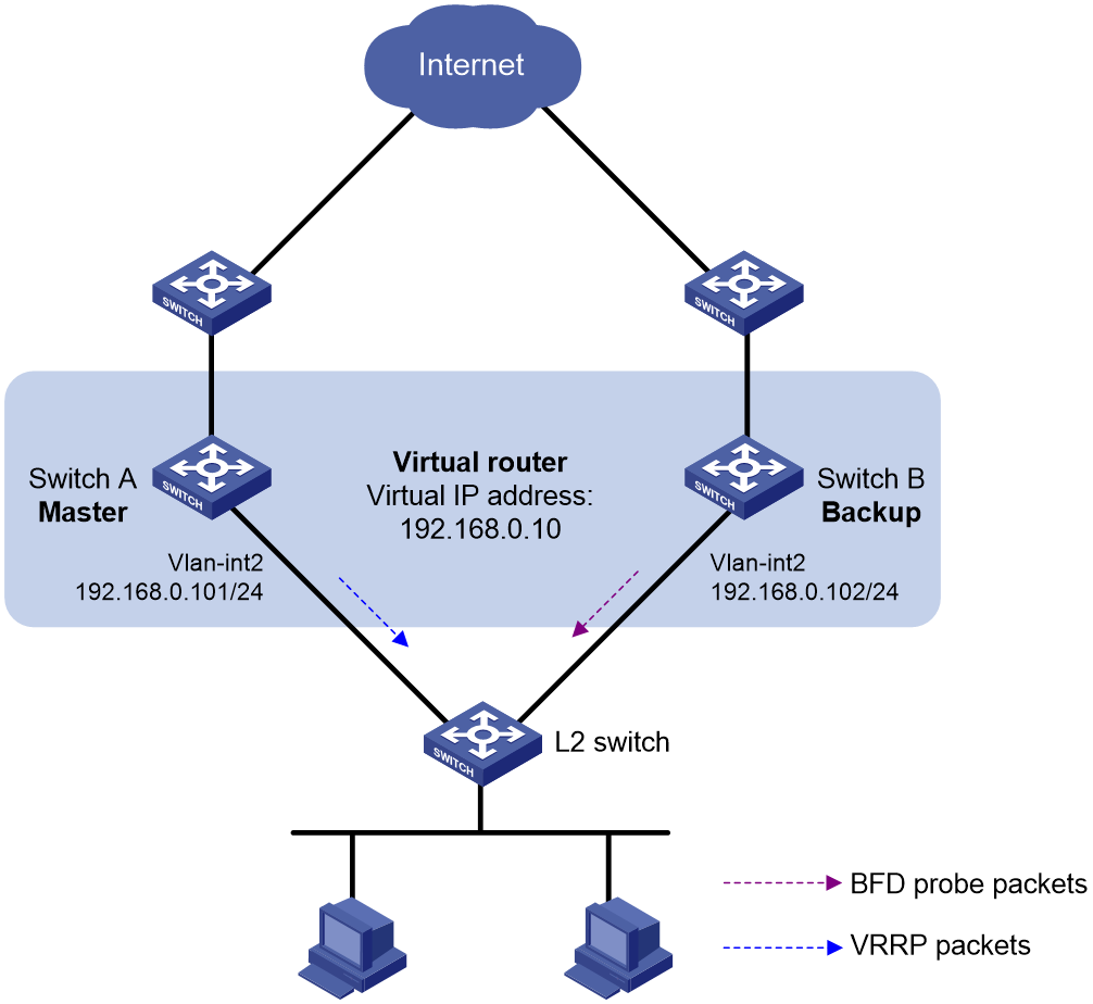
Configuration procedure
1. Create VLANs and assign ports to them. Configure the IP address of each VLAN interface, as shown in Figure 38. (Details not shown.)
2. Configure Switch A:
# Create VRRP group 1, and configure the virtual IP address 192.168.0.10 for the group.
<SwitchA> system-view
[SwitchA] interface vlan-interface 2
[SwitchA-Vlan-interface2] vrrp vrid 1 virtual-ip 192.168.0.10
# Set the priority of Switch A to 110 in VRRP group 1.
[SwitchA-Vlan-interface2] vrrp vrid 1 priority 110
[SwitchA-Vlan-interface2] return
3. Configure Switch B:
# Specify 10.10.10.10 as the source address of BFD echo packets.
<SwitchB> system-view
[SwitchB] bfd echo-source-ip 10.10.10.10
# Create track entry 1, and associate it with the BFD session to verify the reachability of Switch A.
[SwitchB] track 1 bfd echo interface vlan-interface 2 remote ip 192.168.0.101 local ip 192.168.0.102
# Create VRRP group 1, and configure the virtual IP address 192.168.0.10 for the group.
[SwitchB] interface vlan-interface 2
[SwitchB-Vlan-interface2] vrrp vrid 1 virtual-ip 192.168.0.10
# Configure VRRP group 1 to monitor the status of track entry 1.
[SwitchB-Vlan-interface2] vrrp vrid 1 track 1 switchover
[SwitchB-Vlan-interface2] return
Verifying the configuration
# Display detailed information about VRRP group 1 on Switch A.
<SwitchA> display vrrp verbose
IPv4 Virtual Router Information:
Running Mode : Standard
Total number of virtual routers : 1
Interface Vlan-interface2
VRID : 1 Adver Timer : 100
Admin Status : Up State : Master
Config Pri : 110 Running Pri : 110
Preempt Mode : Yes Delay Time : 0
Auth Type : None
Virtual IP : 192.168.0.10
Virtual MAC : 0000-5e00-0101
Master IP : 192.168.0.101
# Display detailed information about VRRP group 1 on Switch B.
<SwitchB> display vrrp verbose
IPv4 Virtual Router Information:
Running Mode : Standard
Total number of virtual routers : 1
Interface Vlan-interface2
VRID : 1 Adver Timer : 100
Admin Status : Up State : Backup
Config Pri : 100 Running Pri : 100
Preempt Mode : Yes Delay Time : 0
Become Master : 2200ms left
Auth Type : None
Virtual IP : 192.168.0.10
Master IP : 192.168.0.101
VRRP Track Information:
Track Object : 1 State : Positive Switchover
# Display information about track entry 1 on Switch B.
<SwitchB> display track 1
Track ID: 1
State: Positive
Duration: 0 days 0 hours 0 minutes 32 seconds
Notification delay: Positive 0, Negative 0 (in seconds)
Tracked object:
BFD session mode: Echo
Outgoing interface: Vlan-interface2
VPN instance name: --
Remote IP: 192.168.0.101
Local IP: 192.168.0.102
The output shows that when the status of the track entry becomes Positive, Switch A is the master and Switch B is the backup.
# Enable VRRP state debugging and BFD event notification debugging on Switch B.
<SwitchB> terminal debugging
<SwitchB> terminal monitor
<SwitchB> debugging vrrp fsm
<SwitchB> debugging bfd ntfy
# When Switch A fails, the following output is displayed on Switch B.
*Dec 17 14:44:34:142 2008 SwitchB BFD/7/DEBUG: Notify application:TRACK State:DOWN
*Dec 17 14:44:34:144 2008 SwitchB VRRP4/7/FSM:
IPv4 Vlan-interface2 | Virtual Router 1 : Backup --> Master reason: The status of the tracked object changed
# Display detailed information about the VRRP group on Switch B.
<SwitchB> display vrrp verbose
IPv4 Virtual Router Information:
Running Mode : Standard
Total number of virtual routers : 1
Interface Vlan-interface2
VRID : 1 Adver Timer : 100
Admin Status : Up State : Master
Config Pri : 100 Running Pri : 100
Preempt Mode : Yes Delay Time : 0
Auth Type : None
Virtual IP : 192.168.0.10
Virtual MAC : 0000-5e00-0101
Master IP : 192.168.0.102
VRRP Track Information:
Track Object : 1 State : Negative Switchover
The output shows that when BFD detects that Switch A fails, the Track module notifies VRRP to change the status of Switch B to master. The backup can quickly preempt as the master without waiting for a period three times the advertisement interval plus the Skew_Time.
Configuring BFD for the VRRP master to monitor the uplinks
Network requirements
As shown in Figure 39:
· Switch A and Switch B belong to VRRP group 1. The virtual IP address of VRRP group 1 is 192.168.0.10.
· The default gateway of the hosts in the LAN is 192.168.0.10.
Configure VRRP-Track-BFD collaboration to monitor the uplink on the master and meet the following requirements:
· When Switch A operates correctly, the hosts in the LAN access the Internet through Switch A.
· When Switch A detects that the uplink is down through BFD, Switch B can preempt as the master. The hosts in the LAN can access the Internet through Switch B.
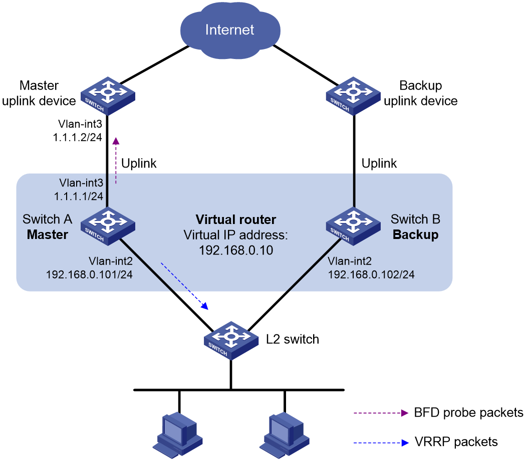
Configuration procedure
1. Create VLANs and assign ports to them. Configure the IP address of each VLAN interface, as shown in Figure 39. (Details not shown.)
2. Configure Switch A:
# Specify 10.10.10.10 as the source address of BFD echo packets.
<SwitchA> system-view
[SwitchA] bfd echo-source-ip 10.10.10.10
# Create track entry 1 for the BFD session to verify the reachability of the uplink device (1.1.1.2 ).
[SwitchA] track 1 bfd echo interface vlan-interface 3 remote ip 1.1.1.2 local ip 1.1.1.1
# Create VRRP group 1, and specify 192.168.0.10 as the virtual IP address of the group.
[SwitchA] interface vlan-interface 2
[SwitchA-Vlan-interface2] vrrp vrid 1 virtual-ip 192.168.0.10
# Set the priority of Switch A to 110 in VRRP group 1.
[SwitchA-Vlan-interface2] vrrp vrid 1 priority 110
# Associate VRRP group 1 with track entry 1 and decrease the router priority by 20 when the state of track entry 1 changes to negative.
[SwitchA-Vlan-interface2] vrrp vrid 1 track 1 priority reduced 20
[SwitchA-Vlan-interface2] return
3. On Switch B, create VRRP group 1, and specify 192.168.0.10 as the virtual IP address of the group.
<SwitchB> system-view
[SwitchB] interface vlan-interface 2
[SwitchB-Vlan-interface2] vrrp vrid 1 virtual-ip 192.168.0.10
[SwitchB-Vlan-interface2] return
Verifying the configuration
# Display detailed information about the VRRP group on Switch A.
<SwitchA> display vrrp verbose
IPv4 Virtual Router Information:
Running Mode : Standard
Total number of virtual routers : 1
Interface Vlan-interface2
VRID : 1 Adver Timer : 100
Admin Status : Up State : Master
Config Pri : 110 Running Pri : 110
Preempt Mode : Yes Delay Time : 0
Auth Type : None
Virtual IP : 192.168.0.10
Virtual MAC : 0000-5e00-0101
Master IP : 192.168.0.101
VRRP Track Information:
Track Object : 1 State : Positive Pri Reduced : 20
# Display information about track entry 1 on Switch A.
<SwitchA> display track 1
Track ID: 1
State: Positive
Duration: 0 days 0 hours 0 minutes 32 seconds
Notification delay: Positive 0, Negative 0 (in seconds)
Tracked object:
BFD session mode: Echo
Outgoing interface: Vlan-interface2
VPN instance name: --
Remote IP: 1.1.1.2
Local IP: 1.1.1.1
# Display detailed information about the VRRP group on Switch B.
<SwitchB> display vrrp verbose
IPv4 Virtual Router Information:
Running Mode : Standard
Total number of virtual routers : 1
Interface Vlan-interface2
VRID : 1 Adver Timer : 100
Admin Status : Up State : Backup
Config Pri : 100 Running Pri : 100
Preempt Mode : Yes Delay Time : 0
Become Master : 2200ms left
Auth Type : None
Virtual IP : 192.168.0.10
Master IP : 192.168.0.101
The output shows that when the status of track entry 1 becomes Positive, Switch A is the master and Switch B is the backup.
# Display information about track entry 1 when the uplink of Switch A goes down.
<SwitchA> display track 1
Track ID: 1
State: Negative
Duration: 0 days 0 hours 0 minutes 32 seconds
Notification delay: Positive 0, Negative 0 (in seconds)
Tracked object:
BFD session mode: Echo
Outgoing interface: Vlan-interface2
VPN instance name: --
Remote IP: 1.1.1.2
Local IP: 1.1.1.1
# Display detailed information about VRRP group 1 on Switch A.
<SwitchA> display vrrp verbose
IPv4 Virtual Router Information:
Running Mode : Standard
Total number of virtual routers : 1
Interface Vlan-interface2
VRID : 1 Adver Timer : 100
Admin Status : Up State : Backup
Config Pri : 110 Running Pri : 90
Preempt Mode : Yes Delay Time : 0
Become Master : 2200ms left
Auth Type : None
Virtual IP : 192.168.0.10
Master IP : 192.168.0.102
VRRP Track Information:
Track Object : 1 State : Negative Pri Reduced : 20
# Display detailed information about VRRP group 1 on Switch B.
<SwitchB> display vrrp verbose
IPv4 Virtual Router Information:
Running Mode : Standard
Total number of virtual routers : 1
Interface Vlan-interface2
VRID : 1 Adver Timer : 100
Admin Status : Up State : Master
Config Pri : 100 Running Pri : 100
Preempt Mode : Yes Delay Time : 0
Auth Type : None
Virtual IP : 192.168.0.10
Virtual MAC : 0000-5e00-0101
Master IP : 192.168.0.102
The output shows that when Switch A detects that the uplink fails through BFD, it decreases its priority by 20. Switch B then preempts as the master.
Static routing-Track-NQA collaboration configuration example
Network requirements
As shown in Figure 40:
· Switch A is the default gateway of the hosts in network 20.1.1.0/24.
· Switch D is the default gateway of the hosts in network 30.1.1.0/24.
· Hosts in the two networks communicate with each other through static routes.
To ensure network availability, configure route backup and static routing-Track-NQA collaboration on Switch A and Switch D as follows:
· On Switch A, assign a higher priority to the static route to 30.1.1.0/24 with the next hop Switch B. This route is the master route. The static route to 30.1.1.0/24 with the next hop Switch C acts as the backup route. When the master route is unavailable, the backup route takes effect. Switch A forwards packets to 30.1.1.0/24 through Switch C.
· On Switch D, assign a higher priority to the static route to 20.1.1.0/24 with the next hop Switch B. This route is the master route. The static route to 20.1.1.0/24 with the next hop Switch C acts as the backup route. When the master route is unavailable, the backup route takes effect. Switch D forwards packets to 20.1.1.0/24 through Switch C.
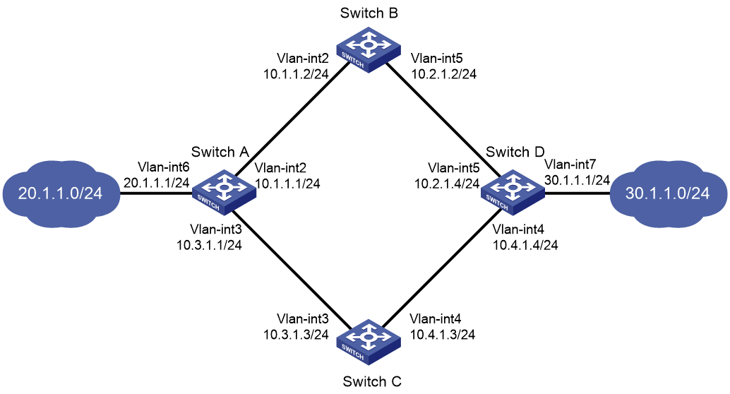
Configuration procedure
1. Create VLANs and assign ports to them. Configure the IP address of each VLAN interface, as shown in Figure 40. (Details not shown.)
2. Configure Switch A:
# Configure a static route to 30.1.1.0/24 with the next hop 10.1.1.2 and the default priority 60. Associate this static route with track entry 1.
<SwitchA> system-view
[SwitchA] ip route-static 30.1.1.0 24 10.1.1.2 track 1
# Configure a static route to 30.1.1.0/24 with the next hop 10.3.1.3 and the priority 80.
[SwitchA] ip route-static 30.1.1.0 24 10.3.1.3 preference 80
# Configure a static route to 10.2.1.4 with the next hop 10.1.1.2.
[SwitchA] ip route-static 10.2.1.4 24 10.1.1.2
# Create an NQA operation with administrator admin and operation tag test.
[SwitchA] nqa entry admin test
# Configure the operation type as ICMP echo.
[SwitchA-nqa-admin-test] type icmp-echo
# Specify 10.2.1.4 as the destination address of the operation.
[SwitchA-nqa-admin-test-icmp-echo] destination ip 10.2.1.4
# Specify 10.1.1.2 as the next hop of the operation.
[SwitchA-nqa-admin-test-icmp-echo] next-hop ip 10.1.1.2
# Configure the ICMP echo operation to repeat every 100 milliseconds.
[SwitchA-nqa-admin-test-icmp-echo] frequency 100
# Configure reaction entry 1, specifying that five consecutive probe failures trigger the Track module.
[SwitchA-nqa-admin-test-icmp-echo] reaction 1 checked-element probe-fail threshold-type consecutive 5 action-type trigger-only
[SwitchA-nqa-admin-test-icmp-echo] quit
# Start the NQA operation.
[SwitchA] nqa schedule admin test start-time now lifetime forever
# Configure track entry 1, and associate it with reaction entry 1 of the NQA operation.
[SwitchA] track 1 nqa entry admin test reaction 1
3. Configure Switch B:
# Configure a static route to 30.1.1.0/24 with the next hop 10.2.1.4.
<SwitchB> system-view
[SwitchB] ip route-static 30.1.1.0 24 10.2.1.4
# Configure a static route to 20.1.1.0/24 with the next hop 10.1.1.1.
[SwitchB] ip route-static 20.1.1.0 24 10.1.1.1
4. Configure Switch C:
# Configure a static route to 30.1.1.0/24 with the next hop 10.4.1.4.
<SwitchC> system-view
[SwitchC] ip route-static 30.1.1.0 24 10.4.1.4
# Configure a static route to 20.1.1.0/24 with the next hop 10.3.1.1.
[SwitchC] ip route-static 20.1.1.0 24 10.3.1.1
5. Configure Switch D:
# Configure a static route to 20.1.1.0/24 with the next hop 10.2.1.2 and the default priority 60. Associate this static route with track entry 1.
<SwitchD> system-view
[SwitchD] ip route-static 20.1.1.0 24 10.2.1.2 track 1
# Configure a static route to 20.1.1.0/24 with the next hop 10.4.1.3 and the priority 80.
[SwitchD] ip route-static 20.1.1.0 24 10.4.1.3 preference 80
# Configure a static route to 10.1.1.1 with the next hop 10.2.1.2.
[SwitchD] ip route-static 10.1.1.1 24 10.2.1.2
# Create an NQA operation with administrator admin and operation tag test.
[SwitchD] nqa entry admin test
# Specify the ICMP echo operation type.
[SwitchD-nqa-admin-test] type icmp-echo
# Specify 10.1.1.1 as the destination address of the operation.
[SwitchD-nqa-admin-test-icmp-echo] destination ip 10.1.1.1
# Specify 10.2.1.2 as the next hop of the operation.
[SwitchD-nqa-admin-test-icmp-echo] next-hop ip 10.2.1.2
# Configure the ICMP echo operation to repeat every 100 milliseconds.
[SwitchD-nqa-admin-test-icmp-echo] frequency 100
# Configure reaction entry 1, specifying that five consecutive probe failures trigger the Track module.
[SwitchD-nqa-admin-test-icmp-echo] reaction 1 checked-element probe-fail threshold-type consecutive 5 action-type trigger-only
[SwitchD-nqa-admin-test-icmp-echo] quit
# Start the NQA operation.
[SwitchD] nqa schedule admin test start-time now lifetime forever
# Configure track entry 1, and associate it with reaction entry 1 of the NQA operation.
[SwitchD] track 1 nqa entry admin test reaction 1
Verifying the configuration
# Display information about the track entry on Switch A.
[SwitchA] display track all
Track ID: 1
State: Positive
Duration: 0 days 0 hours 0 minutes 32 seconds
Notification delay: Positive 0, Negative 0 (in seconds)
Tracked object:
NQA entry: admin test
Reaction: 1
Remote IP/URL: --
Local IP: --
Interface: --
The output shows that the status of the track entry is Positive, indicating that the NQA operation has succeeded and the master route is available.
# Display the routing table of Switch A.
[SwitchA] display ip routing-table
Destinations : 10 Routes : 10
Destination/Mask Proto Pre Cost NextHop Interface
10.1.1.0/24 Direct 0 0 10.1.1.1 Vlan2
10.1.1.1/32 Direct 0 0 127.0.0.1 InLoop0
10.2.1.0/24 Static 60 0 10.1.1.2 Vlan2
10.3.1.0/24 Direct 0 0 10.3.1.1 Vlan3
10.3.1.1/32 Direct 0 0 127.0.0.1 InLoop0
20.1.1.0/24 Direct 0 0 20.1.1.1 Vlan6
20.1.1.1/32 Direct 0 0 127.0.0.1 InLoop0
30.1.1.0/24 Static 60 0 10.1.1.2 Vlan2
127.0.0.0/8 Direct 0 0 127.0.0.1 InLoop0
127.0.0.1/32 Direct 0 0 127.0.0.1 InLoop0
The output shows that Switch A forwards packets to 30.1.1.0/24 through Switch B.
# Remove the IP address of interface VLAN-interface 2 on Switch B.
<SwitchB> system-view
[SwitchB] interface vlan-interface 2
[SwitchB-Vlan-interface2] undo ip address
# Display information about the track entry on Switch A.
[SwitchA] display track all
Track ID: 1
State: Negative
Duration: 0 days 0 hours 0 minutes 32 seconds
Notification delay: Positive 0, Negative 0 (in seconds)
Tracked object:
NQA entry: admin test
Reaction: 1
Remote IP/URL: --
Local IP: --
Interface: --
The output shows that the status of the track entry is Negative, indicating that the NQA operation has failed and the master route is unavailable.
# Display the routing table of Switch A.
[SwitchA] display ip routing-table
Destinations : 10 Routes : 10
Destination/Mask Proto Pre Cost NextHop Interface
10.1.1.0/24 Direct 0 0 10.1.1.1 Vlan2
10.1.1.1/32 Direct 0 0 127.0.0.1 InLoop0
10.2.1.0/24 Static 60 0 10.1.1.2 Vlan2
10.3.1.0/24 Direct 0 0 10.3.1.1 Vlan3
10.3.1.1/32 Direct 0 0 127.0.0.1 InLoop0
20.1.1.0/24 Direct 0 0 20.1.1.1 Vlan6
20.1.1.1/32 Direct 0 0 127.0.0.1 InLoop0
30.1.1.0/24 Static 80 0 10.3.1.3 Vlan3
127.0.0.0/8 Direct 0 0 127.0.0.1 InLoop0
127.0.0.1/32 Direct 0 0 127.0.0.1 InLoop0
The output shows that Switch A forwards packets to 30.1.1.0/24 through Switch C. The backup static route has taken effect.
# Verify that hosts in 20.1.1.0/24 can communicate with the hosts in 30.1.1.0/24 when the master route fails.
[SwitchA] ping -a 20.1.1.1 30.1.1.1
Ping 30.1.1.1: 56 data bytes, press CTRL_C to break
Reply from 30.1.1.1: bytes=56 Sequence=1 ttl=254 time=2 ms
Reply from 30.1.1.1: bytes=56 Sequence=2 ttl=254 time=1 ms
Reply from 30.1.1.1: bytes=56 Sequence=3 ttl=254 time=1 ms
Reply from 30.1.1.1: bytes=56 Sequence=4 ttl=254 time=2 ms
Reply from 30.1.1.1: bytes=56 Sequence=5 ttl=254 time=1 ms
--- Ping statistics for 30.1.1.1 ---
5 packet(s) transmitted, 5 packet(s) received, 0.00% packet loss
round-trip min/avg/max/std-dev = 1/1/2/1 ms
# Verify that the hosts in 30.1.1.0/24 can communicate with the hosts in 20.1.1.0/24 when the master route fails.
[SwitchB] ping -a 30.1.1.1 20.1.1.1
Ping 20.1.1.1: 56 data bytes, press CTRL_C to break
Reply from 20.1.1.1: bytes=56 Sequence=1 ttl=254 time=2 ms
Reply from 20.1.1.1: bytes=56 Sequence=2 ttl=254 time=1 ms
Reply from 20.1.1.1: bytes=56 Sequence=3 ttl=254 time=1 ms
Reply from 20.1.1.1: bytes=56 Sequence=4 ttl=254 time=1 ms
Reply from 20.1.1.1: bytes=56 Sequence=5 ttl=254 time=1 ms
--- Ping statistics for 20.1.1.1 ---
5 packet(s) transmitted, 5 packet(s) received, 0.00% packet loss
round-trip min/avg/max/std-dev = 1/1/2/1 ms
Static routing-Track-BFD collaboration configuration example
Network requirements
As shown in Figure 41:
· Switch A is the default gateway of the hosts in network 20.1.1.0/24.
· Switch B is the default gateway of the hosts in network 30.1.1.0/24.
· Hosts in the two networks communicate with each other through static routes.
To ensure network availability, configure route backup and static routing-Track-BFD collaboration on Switch A and Switch B as follows:
· On Switch A, assign a higher priority to the static route to 30.1.1.0/24 with the next hop Switch B. This route is the master route. The static route to 30.1.1.0/24 with the next hop Switch C acts as the backup route. When the master route is unavailable, BFD can quickly detect the route failure to make the backup route take effect.
· On Switch B, assign a higher priority to the static route to 20.1.1.0/24 with the next hop Switch A. This route is the master route. The static route to 20.1.1.0/24 with the next hop Switch C acts as the backup route. When the master route is unavailable, BFD can quickly detect the route failure to make the backup route take effect.
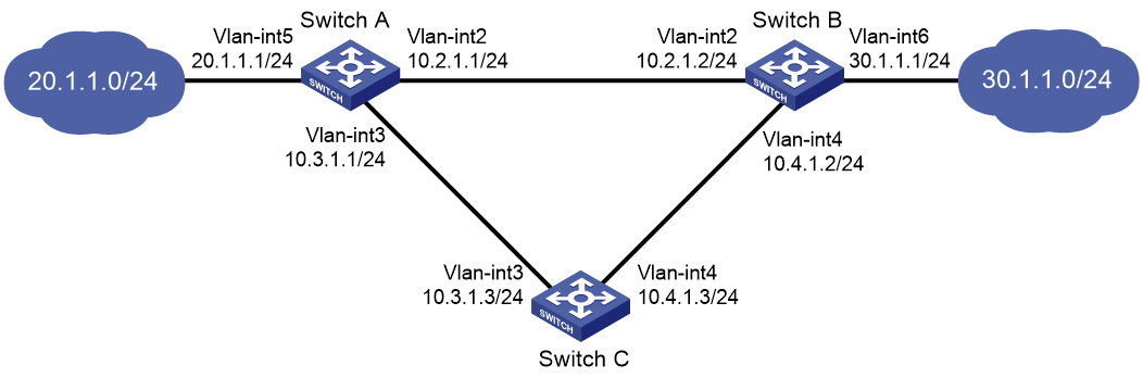
Configuration procedure
1. Create VLANs and assign ports to them. Configure the IP address of each VLAN interface, as shown in Figure 41. (Details not shown.)
2. Configure Switch A:
# Configure a static route to 30.1.1.0/24 with the next hop 10.2.1.2 and the default priority 60. Associate this static route with track entry 1.
<SwitchA> system-view
[SwitchA] ip route-static 30.1.1.0 24 10.2.1.2 track 1
# Configure a static route to 30.1.1.0/24 with the next hop 10.3.1.3 and the priority 80.
[SwitchA] ip route-static 30.1.1.0 24 10.3.1.3 preference 80
# Specify 10.10.10.10 as the source address of BFD echo packets.
[SwitchA] bfd echo-source-ip 10.10.10.10
# Configure track entry 1, and associate it with the BFD session to verify the connectivity between Switch A and Switch B.
[SwitchA] track 1 bfd echo interface vlan-interface 2 remote ip 10.2.1.2 local ip 10.2.1.1
3. Configure Switch B:
# Configure a static route to 20.1.1.0/24 with the next hop 10.2.1.1 and the default priority 60. Associate this static route with track entry 1.
<SwitchB> system-view
[SwitchB] ip route-static 20.1.1.0 24 10.2.1.1 track 1
# Configure a static route to 20.1.1.0/24 with the next hop 10.4.1.3 and the priority 80.
[SwitchB] ip route-static 20.1.1.0 24 10.4.1.3 preference 80
# Specify 1.1.1.1 as the source address of BFD echo packets.
[SwitchB] bfd echo-source-ip 1.1.1.1
# Configure track entry 1, and associate it with the BFD session to verify the connectivity between Switch B and Switch A.
[SwitchB] track 1 bfd echo interface vlan-interface 2 remote ip 10.2.1.1 local ip 10.2.1.2
4. Configure Switch C:
# Configure a static route to 30.1.1.0/24 with the next hop 10.4.1.2.
<SwitchC> system-view
[SwitchC] ip route-static 30.1.1.0 24 10.4.1.2
# Configure a static route to 20.1.1.0/24 with the next hop 10.3.1.1.
[SwitchB] ip route-static 20.1.1.0 24 10.3.1.1
Verifying the configuration
# Display information about the track entry on Switch A.
[SwitchA] display track all
Track ID: 1
State: Positive
Duration: 0 days 0 hours 0 minutes 32 seconds
Notification delay: Positive 0, Negative 0 (in seconds)
Tracked object:
BFD session mode: Echo
Outgoing interface: Vlan-interface2
VPN instance name: --
Remote IP: 10.2.1.2
Local IP: 10.2.1.1
The output shows that the status of the track entry is Positive, indicating that the next hop 10.2.1.2 is reachable.
# Display the routing table of Switch A.
[SwitchA] display ip routing-table
Destinations : 9 Routes : 9
Destination/Mask Proto Pre Cost NextHop Interface
10.2.1.0/24 Direct 0 0 10.2.1.1 Vlan2
10.2.1.1/32 Direct 0 0 127.0.0.1 InLoop0
10.3.1.0/24 Direct 0 0 10.3.1.1 Vlan3
10.3.1.1/32 Direct 0 0 127.0.0.1 InLoop0
20.1.1.0/24 Direct 0 0 20.1.1.1 Vlan5
20.1.1.1/32 Direct 0 0 127.0.0.1 InLoop0
30.1.1.0/24 Static 60 0 10.2.1.2 Vlan2
127.0.0.0/8 Direct 0 0 127.0.0.1 InLoop0
127.0.0.1/32 Direct 0 0 127.0.0.1 InLoop0
The output shows that Switch A forwards packets to 30.1.1.0/24 through Switch B. The master static route has taken effect.
# Remove the IP address of VLAN-interface 2 on Switch B.
<SwitchB> system-view
[SwitchB] interface vlan-interface 2
[SwitchB-Vlan-interface2] undo ip address
# Display information about the track entry on Switch A.
[SwitchA] display track all
Track ID: 1
State: Negative
Duration: 0 days 0 hours 0 minutes 32 seconds
Notification delay: Positive 0, Negative 0 (in seconds)
Tracked object:
BFD session mode: Echo
Outgoing interface: Vlan-interface2
VPN instance name: --
Remote IP: 10.2.1.2
Local IP: 10.2.1.1
The output shows that the status of the track entry is Negative, indicating that the next hop 10.2.1.2 is unreachable.
# Display the routing table of Switch A.
[SwitchA] display ip routing-table
Destinations : 9 Routes : 9
Destination/Mask Proto Pre Cost NextHop Interface
10.2.1.0/24 Direct 0 0 10.2.1.1 Vlan2
10.2.1.1/32 Direct 0 0 127.0.0.1 InLoop0
10.3.1.0/24 Direct 0 0 10.3.1.1 Vlan3
10.3.1.1/32 Direct 0 0 127.0.0.1 InLoop0
20.1.1.0/24 Direct 0 0 20.1.1.1 Vlan5
20.1.1.1/32 Direct 0 0 127.0.0.1 InLoop0
30.1.1.0/24 Static 80 0 10.3.1.3 Vlan3
127.0.0.0/8 Direct 0 0 127.0.0.1 InLoop0
127.0.0.1/32 Direct 0 0 127.0.0.1 InLoop0
The output shows that Switch A forwards packets to 30.1.1.0/24 through Switch C. The backup static route has taken effect.
# Verify that the hosts in 20.1.1.0/24 can communicate with the hosts in 30.1.1.0/24 when the master route fails.
[SwitchA] ping -a 20.1.1.1 30.1.1.1
Ping 30.1.1.1: 56 data bytes, press CTRL_C to break
Reply from 30.1.1.1: bytes=56 Sequence=1 ttl=254 time=2 ms
Reply from 30.1.1.1: bytes=56 Sequence=2 ttl=254 time=1 ms
Reply from 30.1.1.1: bytes=56 Sequence=3 ttl=254 time=1 ms
Reply from 30.1.1.1: bytes=56 Sequence=4 ttl=254 time=2 ms
Reply from 30.1.1.1: bytes=56 Sequence=5 ttl=254 time=1 ms
--- Ping statistics for 30.1.1.1 ---
5 packet(s) transmitted, 5 packet(s) received, 0.00% packet loss
round-trip min/avg/max/std-dev = 1/1/2/1 ms
# Verify that the hosts in 30.1.1.0/24 can still communicate with the hosts in 20.1.1.0/24 when the master route fails.
[SwitchB] ping -a 30.1.1.1 20.1.1.1
Ping 20.1.1.1: 56 data bytes, press CTRL_C to break
Reply from 20.1.1.1: bytes=56 Sequence=1 ttl=254 time=2 ms
Reply from 20.1.1.1: bytes=56 Sequence=2 ttl=254 time=1 ms
Reply from 20.1.1.1: bytes=56 Sequence=3 ttl=254 time=1 ms
Reply from 20.1.1.1: bytes=56 Sequence=4 ttl=254 time=1 ms
Reply from 20.1.1.1: bytes=56 Sequence=5 ttl=254 time=1 ms
--- Ping statistics for 20.1.1.1 ---
5 packet(s) transmitted, 5 packet(s) received, 0.00% packet loss
round-trip min/avg/max/std-dev = 1/1/2/1 ms
VRRP-Track-interface management collaboration configuration example
Network requirements
As shown in Figure 42:
· Host A requires access to Host B. The default gateway of Host A is 10.1.1.10/24.
· Switch A and Switch B belong to VRRP group 1. The virtual IP address of VRRP group 1 is 10.1.1.10.
Configure VRRP-Track-interface management collaboration to monitor the uplink interface on the master and meet the following requirements:
· When Switch A operates correctly, Switch A forwards packets from Host A to Host B.
· When VRRP detects a fault on the uplink interface of Switch A through the interface management module, Switch B forwards packets from Host A to Host B.
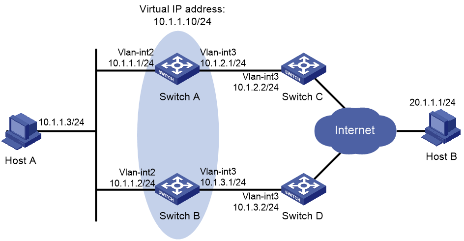
Configuration procedure
1. Create VLANs and assign ports to them. Configure the IP address of each VLAN interface, as shown in Figure 42. (Details not shown.)
2. Configure Switch A:
# Configure track entry 1 and associate it with the link status of the uplink interface VLAN-interface 3.
[SwitchA] track 1 interface vlan-interface 3
# Create VRRP group 1 and configure the virtual IP address 10.1.1.10 for the group.
[SwitchA] interface vlan-interface 2
[SwitchA-Vlan-interface2] vrrp vrid 1 virtual-ip 10.1.1.10
# Set the priority of Switch A to 110 in VRRP group 1.
[SwitchA-Vlan-interface2] vrrp vrid 1 priority 110
# Associate VRRP group 1 with track entry 1 and decrease the router priority by 30 when the state of track entry 1 changes to negative.
[SwitchA-Vlan-interface2] vrrp vrid 1 track 1 priority reduced 30
3. On Switch B, create VRRP group 1, and configure the virtual IP address 10.1.1.10 for the group.
<SwitchB> system-view
[SwitchB] interface vlan-interface 2
[SwitchB-Vlan-interface2] vrrp vrid 1 virtual-ip 10.1.1.10
Verifying the configuration
# Ping Host B from Host A to verify that Host B is reachable. (Details not shown.)
# Display detailed information about VRRP group 1 on Switch A.
[SwitchA-Vlan-interface2] display vrrp verbose
IPv4 Virtual Router Information:
Running Mode : Standard
Total number of virtual routers : 1
Interface Vlan-interface2
VRID : 1 Adver Timer : 100
Admin Status : Up State : Master
Config Pri : 110 Running Pri : 110
Preempt Mode : Yes Delay Time : 0
Auth Type : None
Virtual IP : 10.1.1.10
Virtual MAC : 0000-5e00-0101
Master IP : 10.1.1.1
VRRP Track Information:
Track Object : 1 State : Positive Pri Reduced : 30
# Display detailed information about VRRP group 1 on Switch B.
[SwitchB-Vlan-interface2] display vrrp verbose
IPv4 Virtual Router Information:
Running Mode : Standard
Total number of virtual routers : 1
Interface Vlan-interface2
VRID : 1 Adver Timer : 100
Admin Status : Up State : Backup
Config Pri : 100 Running Pri : 100
Preempt Mode : Yes Delay Time : 0
Become Master : 2200ms left
Auth Type : None
Virtual IP : 10.1.1.10
Master IP : 10.1.1.1
The output shows that in VRRP group 1, Switch A is the master, and Switch B is a backup. Switch A forwards packets from Host A to Host B.
# Shut down the uplink interface VLAN-interface 3 on Switch A.
[SwitchA-Vlan-interface2] interface vlan-interface 3
[SwitchA-Vlan-interface3] shutdown
# Ping Host B from Host A to verify that Host B is reachable. (Details not shown.)
# Display detailed information about VRRP group 1 on Switch A.
[SwitchA-Vlan-interface3] display vrrp verbose
IPv4 Virtual Router Information:
Running Mode : Standard
Total number of virtual routers : 1
Interface Vlan-interface2
VRID : 1 Adver Timer : 100
Admin Status : Up State : Backup
Config Pri : 110 Running Pri : 80
Preempt Mode : Yes Delay Time : 0
Become Master : 2200ms left
Auth Type : None
Virtual IP : 10.1.1.10
Master IP : 10.1.1.2
VRRP Track Information:
Track Object : 1 State : Negative Pri Reduced : 30
# Display detailed information about VRRP group 1 on Switch B.
[SwitchB-Vlan-interface2] display vrrp verbose
IPv4 Virtual Router Information:
Running Mode : Standard
Total number of virtual routers : 1
Interface Vlan-interface2
VRID : 1 Adver Timer : 100
Admin Status : Up State : Master
Config Pri : 100 Running Pri : 100
Preempt Mode : Yes Delay Time : 0
Auth Type : None
Virtual IP : 10.1.1.10
Virtual MAC : 0000-5e00-0101
Master IP : 10.1.1.2
The output shows that Switch A becomes the backup, and Switch B becomes the master. Switch B forwards packets from Host A to Host B.
VRRP-Track-route management collaboration configuration example
Network requirements
As shown in Figure 43:
· Host A requires access to Host B. The default gateway of Host A is 10.1.1.10/24.
· Switch A and Switch B belong to VRRP group 1. The virtual IP address of VRRP group 1 is 10.1.1.10.
· BGP peer relationships are established between Switch A and Switch C and between Switch B and Switch D. Switch C and Switch D advertise the default route 0.0.0.0/0 to Switch A and Switch B.
Configure VRRP-Track-route management collaboration to meet the following requirements:
· When Switch A operates correctly, Switch A forwards packets from Host A to Host B.
· When VRRP detects the removal of the default route from the routing table of Switch A through route management, Switch B forwards packets from Host A to Host B.
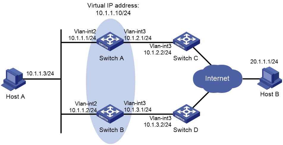
Configuration procedure
1. Configure the IP address of each interface, as shown in Figure 43. (Details not shown.)
2. Establish an IBGP peer relationship between Switch A and Switch C, and configure Switch C to advertise the default route 0.0.0.0/0 to Switch A.
<SwitchA> system-view
[SwitchA] bgp 100
[SwitchA-bgp-default] peer 10.1.2.2 as-number 100
[SwitchA-bgp-default] address-family ipv4
[SwitchA-bgp-default-ipv4] peer 10.1.2.2 enable
<SwitchC> system-view
[SwitchC] bgp 100
[SwitchC-bgp-default] peer 10.1.2.1 as-number 100
[SwitchC-bgp-default] address-family ipv4
[SwitchC-bgp-default-ipv4] peer 10.1.2.1 enable
[SwitchC-bgp-default-ipv4] peer 10.1.2.1 default-route-advertise
[SwitchC-bgp-default-ipv4] quit
3. Configure Switch B and Switch D in the same way Switch A and Switch C are configured. (Details not shown.)
4. Configure Track and VRRP on Switch A:
# Configure track entry 1, and associate it with the default route 0.0.0.0/0.
[SwitchA] track 1 ip route 0.0.0.0 0.0.0.0 reachability
# Create VRRP group 1, and configure the virtual IP address 10.1.1.10 for the group.
[SwitchA] interface vlan-interface 2
[SwitchA-Vlan-interface2] vrrp vrid 1 virtual-ip 10.1.1.10
# Set the priority of Switch A to 110 in VRRP group 1.
[SwitchA-Vlan-interface2] vrrp vrid 1 priority 110
# Associate VRRP group 1 with track entry 1 and decrease the Switch priority by 30 when the state of track entry 1 changes to negative.
[SwitchA-Vlan-interface2] vrrp vrid 1 track 1 priority reduced 30
[SwitchA-Vlan-interface2] quit
5. On Switch B, create VRRP group 1, and configure the virtual IP address 10.1.1.10 for the group.
<SwitchB> system-view
[SwitchB] interface vlan-interface 2
[SwitchB-Vlan-interface2] vrrp vrid 1 virtual-ip 10.1.1.10
[SwitchB-Vlan-interface2] quit
Verifying the configuration
# Ping Host B from Host A to verify that Host B is reachable. (Details not shown.)
# Display detailed information about VRRP group 1 on Switch A.
[SwitchA] display vrrp verbose
IPv4 Virtual Router Information:
Running Mode : Standard
Total number of virtual routers : 1
Interface Vlan-interface2
VRID : 1 Adver Timer : 100
Admin Status : Up State : Master
Config Pri : 110 Running Pri : 110
Preempt Mode : Yes Delay Time : 0
Auth Type : None
Virtual IP : 10.1.1.10
Virtual MAC : 0000-5e00-0101
Master IP : 10.1.1.1
VRRP Track Information:
Track Object : 1 State : Positive Pri Reduced : 30
# Display detailed information about VRRP group 1 on Switch B.
[SwitchB] display vrrp verbose
IPv4 Virtual Router Information:
Running Mode : Standard
Total number of virtual routers : 1
Interface Vlan-interface2
VRID : 1 Adver Timer : 100
Admin Status : Up State : Backup
Config Pri : 100 Running Pri : 100
Preempt Mode : Yes Delay Time : 0
Become Master : 2200ms left
Auth Type : None
Virtual IP : 10.1.1.10
Master IP : 10.1.1.1
The output shows that in VRRP group 1, Switch A is the master and Switch B is a backup. Switch A forwards packets from Host A to Host B.
# Disable Switch C from exchanging routing information with Switch A so that the default route 0.0.0.0/0 is removed from the routing table of Switch A.
[SwitchC-bgp-default-ipv4] undo peer 10.1.2.1 enable
# Ping Host B from Host A to verify that Host B is reachable. (Details not shown.)
# Display detailed information about VRRP group 1 on Switch A.
[SwitchA] display vrrp verbose
IPv4 Virtual Router Information:
Running Mode : Standard
Total number of virtual routers : 1
Interface Vlan-interface2
VRID : 1 Adver Timer : 100
Admin Status : Up State : Backup
Config Pri : 110 Running Pri : 80
Preempt Mode : Yes Delay Time : 0
Become Master : 2200ms left
Auth Type : None
Virtual IP : 10.1.1.10
Master IP : 10.1.1.2
VRRP Track Information:
Track Object : 1 State : Negative Pri Reduced : 30
# Display detailed information about VRRP group 1 on Switch B.
[SwitchB] display vrrp verbose
IPv4 Virtual Router Information:
Running Mode : Standard
Total number of virtual routers : 1
Interface Vlan-interface2
VRID : 1 Adver Timer : 100
Admin Status : Up State : Master
Config Pri : 100 Running Pri : 100
Preempt Mode : Yes Delay Time : 0
Auth Type : None
Virtual IP : 10.1.1.10
Virtual MAC : 0000-5e00-0101
Master IP : 10.1.1.2
The output shows that Switch A becomes the backup, and Switch B becomes the master. Switch B forwards packets from Host A to Host B.
Configuring process placement
Overview
Process placement enables placing processes to specific CPUs (also called nodes) on the main processing units (MPUs) in your system for optimal distribution of CPU and memory resources.
Process
A process contains a set of codes and provides specific functionality. For example, an AAA process provides AAA functions.
Each process runs in a protected memory space to prevent problems with one process from impacting the entire system.
1:N process redundancy
The system backs up each active process running on one node to all the other nodes. When an active process fails, one of its standby processes promptly takes over without impacting any other service.
1:N process redundancy provides the following benefits:
· Improves service availability.
· Enables the system to quickly regain reliability after device status changes in such conditions as insertion and removal of cards, IRF split, and removal of an IRF member.
Process placement policy and optimization
Process placement policies
(In standalone mode.) The execution of process placement policies varies by the location of active processes.
· An active process running only on the active MPU does not support placement optimization. If you configure a process placement policy for the process, the system displays a configuration failure message. When such an active process fails, the system automatically restarts the process. The standby processes are used for active/standby switchover and ISSU.
· Some active processes can run on either the active or standby MPU. When such an active process fails, the system uses a placement policy to select a new active process among standby processes.
(In IRF mode.) The execution of process placement policies varies by the location of active processes.
· An active process running only on the global active MPU does not support placement optimization. If you configure a process placement policy for the process, the system displays a configuration failure message. When such an active process fails, the system automatically restarts the process. The standby processes are used for active/standby switchover and ISSU.
· Some active processes can run on either the global active or standby MPU. When such an active process fails, the system uses a placement policy to select a new active process among standby processes.
The system provides a default process placement policy that takes effect for all processes. You can modify the default placement policy in the view you enter by using the placement program default command. You can also configure a placement policy for a specific process in the view you enter by using the placement program program-name [ instance instance-name ] command. A placement policy for a process takes precedence over the default process placement policy.
By default, the default process placement policy defines the following rules:
· (In standalone mode.) The active process runs on the CPU of the active MPU, and the standby processes run on the CPU of the standby MPU.
· (In IRF mode.) The active process runs on the CPU of the global active MPU, and the standby processes run on the CPU of the global standby MPU.
· A process runs at the location where it ran the last time and does not move to any other location during startup or operation.
· The addition of a new node does not impact current active processes. A new active process selects one node with sufficient CPU and memory resources. (You can use the display cpu-usage and display memory commands to view CPU and memory usage information.)
Optimizing process placement
You can configure the following settings for a process placement policy to optimize process placement:
· affinity location-set—Location affinity, the preference for the process to run on a specific node.
· affinity location-type—Location type affinity, the preference for the process to run on a particular type of node. For more information about node types, see "Configuring a location type affinity."
· affinity program—Process affinity, the preference for the process to run on the same node as a particular process.
· affinity self—Self affinity, the preference for one instance of the process to run on the same node as any other instance of the process.
Affinities include positive affinities (attract) and negative affinities (repulse), all represented by integers in the range of 1 to 100000.
· The higher the attract value, the stronger the preference.
· The higher the repulse value, the weaker the preference.
After you apply new placement policies, the system makes placement decisions based on the new policies, node resources, and topology status. If the new location for an active process is different from the current node, the system changes the state of the process to standby, and uses the standby process on the preferred location as the new active process.
Configuration restrictions and guidelines
When you configure process placement, follow these restrictions and guidelines:
· Configuring process placement on a device with only one MPU does not change the location of processes. All processes run on the CPU of the MPU.
· Configuring process placement on a device with multiple MPUs places specific active processes to specific CPUs. In case of multiple CPUs, the system performs 1:N process redundancy. The number of standby processes and their CPU locations vary by function module. The system by default automatically determines the location for each active process, and process placement optimization is not required. If optimization is required, contact H3C Support to avoid service interruption.
· Process placement applies only to MPUs.
· To view the current location of an active process and its predicted new location after optimization, use the display placement reoptimize command.
Process placement configuration task list
|
Tasks at a glance |
|
|
Configuring process placement policy: · (Optional.) Configuring a location affinity · (Optional.) Configuring a location type affinity · (Optional.) Configuring a process affinity · (Optional.) Configuring a self affinity |
|
|
(Required.) Optimizing process placement |
Configuring process placement policy
Configuring a location affinity
|
Step |
Command |
Remarks |
|
1. Enter system view. |
system-view |
N/A |
|
2. Enter placement process view. |
· Enter default placement process view: · Enter placement process view: |
Settings in default placement process view take effect for all processes. Settings in placement process view take effect only for the specified process. |
|
3. Set the location affinity. |
In standalone mode: In IRF mode: |
By default, no location affinity is set. |
Configuring a location type affinity
The following location types are available:
· current—Current location of the active process, which can be displayed with the display placement program command.
· paired—Locations of standby processes.
· (In standalone mode.) primary—Active MPU.
· (In IRF mode.) primary—Global active MPU.
To configure a location type affinity:
|
Step |
Command |
Remarks |
|
1. Enter system view. |
system-view |
N/A |
|
2. Enter placement process view. |
· Enter default placement process view: · Enter placement process view: |
Settings in default placement process view take effect for all processes. Settings in placement process view take effect only for the specified process. |
|
3. Set the location type affinity. |
affinity location-type { current | paired | primary } { attract strength | repulse strength | default | none } |
By default, no location type affinity is set. |
Configuring a process affinity
|
Step |
Command |
Remarks |
|
1. Enter system view. |
system-view |
N/A |
|
2. Enter placement process view. |
· Enter default placement process view: · Enter placement process view: |
Settings in default placement process view take effect for all processes. Settings in placement process view take effect only for the specified process. |
|
3. Configure the affinity for the process to run on the same location as another process. |
affinity program program-name { attract strength | default | none | repulse strength } |
By default, no process affinity is set. |
Configuring a self affinity
Perform this task to configure the preference for one instance of a process to run on the same node as any other instance of the process. The self affinity setting does not take effect for a process that has only one instance.
To configure a self affinity:
|
Step |
Command |
Remarks |
|
1. Enter system view. |
system-view |
N/A |
|
2. Enter placement process view. |
· Enter default placement process view: · Enter placement process view: |
Settings in default placement process view take effect for all processes. Settings in placement process view take effect only for the specified process. |
|
3. Configure a self affinity. |
affinity self { attract strength | repulse strength | default | none } |
By default, no self affinity is set. |
Optimizing process placement
|
Step |
Command |
Remarks |
|
1. Enter system view. |
system-view |
N/A |
|
2. Optimize process placement. |
placement reoptimize |
To keep the system stable, do not perform any tasks that require process restart when you execute this command. |
Displaying process placement
Execute display commands in any view.
|
Task |
Command |
|
Display process placement policy information. |
display placement policy program { program-name | all | default } |
|
Display the location of a process. |
display placement program { program-name | all } |
|
(In standalone mode.) Display the running processes on a specific location. |
display placement location { slot slot-number | all } |
|
(In IRF mode.) Display the running processes on a specific location. |
display placement location { chassis chassis-number slot slot-number | all } |
|
Display the predicted location of a process after process placement optimization. |
display placement reoptimize program { program-name [ instance instance-name ] | all } |
|
Display service group information. |
display ha service-group { program-name [ instance instance-name ] | all } |
Numerics
1\:N process redundancy, 169
A
action
Ethernet OAM port action, 7
activating
RRPP domain, 36
active virtual forwarder. Use AVF
advertising
DLDP advertisement packet send interval, 15
DLDP advertisement timer, 11
VRRP advertisement interval, 84
affinity
process placement affinity (location type), 171
process placement affinity (location), 171
process placement affinity (process), 172
process placement affinity (self), 172
process placement location-set, 170
process placement location-type, 170
process placement negative (repulse) affinity, 170
process placement positive (attract) affinity, 170
process placement program, 170
process placement self, 170
application
NQA+Track+static routing collaboration, 137
Track+application module association, 140
Track+EAA association, 144
Track+policy-based routing association, 142
Track+static routing association, 141
Track+VRRP association, 140
Track+VRRP group association, 141
Track+VRRP VF association, 141
Track+VXLAN association, 144
VRRP, 85
VRRP load-sharing, 86
VRRP master/backup, 85
ARP
VRRP virtual MAC address assignment, 87
assigning
IPv4 VRRP virtual IP address, 92
IPv6 VRRP virtual IP address, 97
VRRP virtual MAC address assignment, 87
assistant-edge node
RRPP specification, 36
RRPP type, 25
associating
Smart Link associated device, 63
Track+application module, 140
Track+BFD, 138
Track+detection modules, 138
Track+EAA, 144
Track+interface management, 139
Track+NQA, 138
Track+policy-based routing, 142
Track+route management, 139
Track+static routing, 141
Track+VRRP, 140
Track+VRRP group, 141
Track+VRRP VF, 141
Track+VXLAN, 144
attribute
IPv4 VRRP packet attribute, 94
IPv6 VRRP packet attribute, 99
authenticating
DLDP MD5 authentication, 16
DLDP MD5 mode, 12
DLDP non-authentication mode, 12
DLDP password authentication, 16
DLDP plaintext authentication, 16
DLDP plaintext mode, 12
DLDP simple authentication, 16
VRRP MD5 authentication, 84
VRRP simple authentication, 84
auto
DLDP automatic unidirectional link shutdown, 17
automatic
high availability DLDP automatic unidirectional link shutdown, 17
VRRP virtual forwarder (VF) weight/priority, 89
B
backing up
Smart Link backup, 59
Track+EAA association, 144
Track+VXLAN association, 144
VRRP virtual forwarder (VF) backup, 90
basic configuration, 133
configuration, 131
control packet mode configuration, 134
display, 135
echo packet mode configuration, 133
maintain, 135
multihop detection, 131
protocols and standards, 132
session establishment+termination, 131
session modes, 131
session+operating modes, 131
single-hop detection, 131
SNMP notification enable, 135
static routing+Track+BFD collaboration (on switch), 159
supported features, 132
Track BFD+VRRP backup master monitor (on switch), 149
Track BFD+VRRP master uplink monitor (on switch), 151
Track+BFD association, 138
VRRP tracking, 85
bidirectional
DLDP port state, 11
forwarding detection. Use BFD
broadcast
RRPP storm suppression, 28
C
collaborating
NQA+Track+static routing collaboration, 137
Smart Link+Monitor Link, 60
static routing+Track+BFD collaboration (on switch), 159
static routing+Track+NQA collaboration (on switch), 155
Track BFD+VRRP backup master monitor (on switch), 149
Track BFD+VRRP master uplink monitor (on switch), 151
Track configuration, 136, 137
Track configuration (on switch), 145
Track+application modules, 136
Track+detection modules, 136
VRRP+Track+interface management collaboration (on switch), 162
VRRP+Track+NQA collaboration (on switch), 145
VRRP+Track+route management collaboration (on switch), 165
common
RRPP common port, 25
RRPPDU common-flush-FDB type, 26
complete-flush-FDB RRPPDU type, 26
configuring
BFD, 131
BFD basic functions, 133
BFD control packet mode, 134
BFD echo packet mode, 133
DLDP, 10, 14, 17
DLDP authentication, 16
DLDP automatic unidirectional link shutdown, 17
Ethernet OAM, 1, 3, 8
Ethernet OAM basics, 3
Ethernet OAM connection detection timer, 4
Ethernet OAM errored frame event detection, 5
Ethernet OAM errored frame period event detection, 6
Ethernet OAM errored seconds period event detection, 6
Ethernet OAM errored symbol event detection, 4
Ethernet OAM link monitoring, 4
Ethernet OAM port action, 7
IPv4 VRRP, 91, 101
IPv4 VRRP load balancing, 106
IPv4 VRRP multiple groups, 103
IPv4 VRRP packet attributes, 94
IPv4 VRRP router preemptive mode, 93
IPv4 VRRP router priority, 93
IPv4 VRRP router tracking function, 93
IPv4 VRRP single group, 101
IPv6 VRRP, 96, 114
IPv6 VRRP load balancing, 121
IPv6 VRRP multiple groups, 117
IPv6 VRRP packet attribute, 99
IPv6 VRRP router preemptive mode, 98
IPv6 VRRP router priority, 98
IPv6 VRRP router tracking function, 98
IPv6 VRRP single group, 114
Monitor Link, 74, 75, 77
Monitor Link group downlink interface switchover delay, 77
Monitor Link group member interface, 76
Monitor Link group member interface (group view), 76
Monitor Link group member interface (interface view), 76
Monitor Link group uplink interface switchover threshold, 77
process placement, 169, 171
process placement policy, 171
process placement policy affinity (location type), 171
process placement policy affinity (location), 171
process placement policy affinity (process), 172
process placement policy affinity (self), 172
RRPP, 24, 32, 38
RRPP control VLAN, 32
RRPP intersecting rings, 41
RRPP load-balanced intersecting rings, 47
RRPP node, 35
RRPP port, 34
RRPP protected VLAN, 33
RRPP ring, 34
RRPP ring group, 37
RRPP single ring, 38
RRPP timer, 37
Smart Link, 58, 60, 64
Smart Link associated device, 63
Smart Link device, 61
Smart Link group (multiple group load sharing), 69
Smart Link group (single group), 64
Smart Link group member port (group view), 62
Smart Link group member port (interface view), 62
Smart Link group protected VLAN, 61
Smart Link group role preemption mode, 62
static routing+Track+BFD collaboration (on switch), 159
static routing+Track+NQA collaboration (on switch), 155
Track, 136, 137
Track (on switch), 145
Track BFD+VRRP backup master monitor (on switch), 149
Track BFD+VRRP master uplink monitor (on switch), 151
VRRP, 82
VRRP virtual forwarder (VF) tracking, 95
VRRP virtual forwarder tracking (VF), 99
VRRP+Track+interface management collaboration (on switch), 162
VRRP+Track+NQA collaboration (on switch), 145
VRRP+Track+route management collaboration (on switch), 165
confirmed DLDP neighbor state, 11
connecting
Ethernet OAM connection detection timer, 4
Ethernet OAM connection establishment, 2
control VLAN
RRPP, 25
RRPP configuration, 32
controlling
BFD control packet mode, 134
CPU
process placement configuration, 169, 171
creating
IPv4 VRRP group, 92
IPv6 VRRP group, 97
Monitor Link group, 75
RRPP domain, 32
D
DelayDown timer (DLDP), 11, 15
detecting
BFD configuration, 131
DLDP automatic unidirectional link shutdown, 17
DLDP configuration, 10, 14, 17
DLDP manual unidirectional link shutdown, 20
DLDP multiple neighbors detection, 13
DLDP single neighbor detection, 12
Ethernet OAM connection detection timer, 4
Ethernet OAM errored frame event detection, 5
Ethernet OAM errored frame period event detection, 6
Ethernet OAM errored frame seconds event detection, 6
Ethernet OAM errored symbol event detection, 4
NQA+Track+static routing collaboration, 137
Track configuration, 136
Track+application module collaboration, 136
Track+BFD association, 138
Track+detection module association, 138
Track+detection module collaboration, 136
Track+interface management association, 139
Track+NQA association, 138
Track+route management association, 139
device
Device Link Detection Protocol. Use DLDP
DLDP automatic unidirectional link shutdown, 17
DLDP configuration, 10, 14, 17
DLDP manual unidirectional link shutdown, 20
Ethernet OAM basic configuration, 3
Ethernet OAM configuration, 1, 3, 8
IPv4 VRRP configuration, 101
IPv4 VRRP load balancing configuration, 106
IPv4 VRRP multiple groups configuration, 103
IPv4 VRRP router preemptive mode, 93
IPv4 VRRP router priority, 93
IPv4 VRRP router tracking, 93
IPv4 VRRP single group configuration, 101
IPv6 VRRP configuration, 114
IPv6 VRRP load balancing configuration, 121
IPv6 VRRP multiple groups configuration, 117
IPv6 VRRP router preemptive mode, 98
IPv6 VRRP router priority, 98
IPv6 VRRP router tracking function, 98
IPv6 VRRP single group configuration, 114
Monitor Link configuration, 74, 75, 77
Monitor Link group creation, 75
Monitor Link group downlink interface switchover delay, 77
Monitor Link group member interface, 76
Monitor Link group uplink interface switchover threshold, 77
process placement configuration, 169, 171
RRPP domain activation, 36
RRPP domain creation, 32
Smart Link associated device, 63
Smart Link device, 61
static routing+Track+BFD collaboration (on switch), 159
static routing+Track+NQA collaboration (on switch), 155
Track BFD+VRRP backup master monitor (on switch), 149
Track BFD+VRRP master uplink monitor (on switch), 151
Track configuration (on switch), 145
VRRP group router priority, 83
VRRP router preemption modes, 84
VRRP tracking, 85
VRRP+Track+interface management collaboration (on switch), 162
VRRP+Track+NQA collaboration (on switch), 145
VRRP+Track+route management collaboration (on switch), 165
disabling
IPv4 VRRP group, 96
IPv6 VRRP group, 100
disconnect state (RRPP ring), 25
displaying
BFD, 135
DLDP, 16
Ethernet OAM, 8
IPv4 VRRP, 96
IPv6 VRRP, 100
Monitor Link, 77
process placement, 173
RRPP, 38
Smart Link, 64
Track entries, 145
advertisement packet send interval, 15
authentication configuration, 16
authentication modes, 12
automatic unidirectional link shutdown, 17, 17
basic concepts, 11
configuration, 10, 14, 17
configuration restrictions, 14
DelayDown timer, 15
display, 16
enable, 14
how it works, 12
maintain, 16
manual unidirectional link shutdown, 20
multiple neighbors detection, 13
neighbor states, 11
port shutdown mode, 15
port states, 11
single neighbor detection, 12
timers, 11
domain
RRPP, 24
RRPP activation, 36
RRPP creation, 32
downlink
Monitor Link group downlink interface switchover delay, 77
dual-homed rings
RRPP network, 30
E
Track+EAA association, 144
echo
BFD echo packet mode, 133
DLDP echo timer, 11
edge
RRPP assistant edge node, 36
RRPP edge node, 36
RRPP node type, 25
RRPP port type, 25
RRPPDU edge-hello type, 26
electing
VRRP master election, 85
Embedded Automation Architecture. Use EAA
enabling
BFD SNMP notifications, 135
DLDP, 14
RRPP SNMP notification, 38
Smart Link flush message reception, 63
Smart Link flush message send, 63
VRRP SNMP notification, 95
enhanced timer (DLDP), 11
entry timer (DLDP), 11
errored
Ethernet OAM errored frame event detection, 5
Ethernet OAM errored frame period event detection, 6
Ethernet OAM errored frame seconds event detection, 6
Ethernet OAM errored symbol event detection, 4
establishing
BFD session, 131
Ethernet OAM connection, 2
Ethernet
OAM. See Ethernet OAM
RRPP configuration, 24, 32, 38
RRPP intersecting rings configuration, 41
RRPP load-balanced intersecting rings configuration, 47
RRPP single ring configuration, 38
basic configuration, 3
configuration, 1, 3, 8
connection detection timer, 4
connection establishment, 2
display, 8
errored frame event detection, 5
errored frame period event detection, 6
errored frame seconds event detection, 6
errored symbol event detection, 4
functions, 1
how it works, 1
link monitoring, 2
link monitoring configuration, 4
maintain, 8
OAMPDUs, 1
port action configuration, 7
protocols and standards, 3
event
Ethernet OAM errored frame event detection, 5
Ethernet OAM errored frame period event detection, 6
Ethernet OAM errored frame seconds event detection, 6
Ethernet OAM errored symbol event detection, 4
F
fail timer (RRPP), 27
fast
BFD fast failure detection, 131
fault
Ethernet OAM functions, 1
fault detection
BFD basic configuration, 133
BFD configuration, 131
flushing
Smart Link flush message, 59
Smart Link flush message reception, 63
Smart Link flush message send, 63
Smart Link flush update, 60
forwarding
bidirectional detection. Use BFD
VRRP virtual forwarder (VF), 89
VRRP virtual forwarder (VF) tracking, 95
VRRP virtual forwarder tracking (VF), 99
G
group
IPv4 VRRP group disable, 96
IPv6 VRRP group disable, 100
Monitor Link downlink interface switchover delay, 77
Monitor Link group creation, 75
Monitor Link group member interface, 76
Monitor Link uplink interface switchover threshold, 77
RRPP ring, 26, 28
RRPP ring group configuration, 37
Smart Link group, 59
Smart Link group configuration (multiple group load sharing), 69
Smart Link group configuration (single group), 64
Smart Link group member ports, 62
Smart Link group protected VLAN, 61
Smart Link group role preemption mode, 62
VRRP, 83
VRRP group router priority, 83
H
hardware
BFD configuration, 131
health
RRPP ring state, 25
hello
RRPP timer, 27
RRPP timer configuration, 37
RRPPDU type, 26
high availability
BFD configuration, 131
BFD display, 135
BFD maintain, 135
BFD protocols and standards, 132
BFD session establishment+termination, 131
BFD session+operating modes, 131
BFD SNMP notification enable, 135
DLDP automatic unidirectional link shutdown, 17, 17
DLDP configuration, 10, 14, 17
DLDP configuration restrictions, 14
DLDP display, 16
DLDP enable, 14
DLDP maintain, 16
DLDP manual unidirectional link shutdown, 20
Ethernet OAM. See Ethernet OAM
Ethernet OAM basic configuration, 3
Ethernet OAM configuration, 3, 8
Ethernet OAM connection detection timer, 4
Ethernet OAM display, 8
Ethernet OAM errored frame event detection, 5
Ethernet OAM errored frame period event detection, 6
Ethernet OAM errored frame seconds event detection, 6
Ethernet OAM errored symbol event detection, 4
Ethernet OAM functions, 1
Ethernet OAM link monitoring configuration, 4
Ethernet OAM maintain, 8
Ethernet OAM OAMPDUs, 1
Ethernet OAM port action, 7
Ethernet OAM protocols and standards, 3
IPv4 VRRP configuration, 91, 101
IPv4 VRRP display, 96
IPv4 VRRP group creation, 92
IPv4 VRRP group disable, 96
IPv4 VRRP load balancing configuration, 106
IPv4 VRRP maintain, 96
IPv4 VRRP multiple groups configuration, 103
IPv4 VRRP operating mode specification, 92
IPv4 VRRP packet attribute, 94
IPv4 VRRP router preemptive mode, 93
IPv4 VRRP router priority, 93
IPv4 VRRP router tracking, 93
IPv4 VRRP single group configuration, 101
IPv4 VRRP version specification, 92
IPv4 VRRP virtual IP address assignment, 92
IPv6 VRRP configuration, 96, 114
IPv6 VRRP display, 100
IPv6 VRRP group creation, 97
IPv6 VRRP group disable, 100
IPv6 VRRP load balancing configuration, 121
IPv6 VRRP maintain, 100
IPv6 VRRP multiple groups configuration, 117
IPv6 VRRP operating mode specification, 97
IPv6 VRRP packet attribute, 99
IPv6 VRRP router preemptive mode, 98
IPv6 VRRP router priority, 98
IPv6 VRRP router tracking function, 98
IPv6 VRRP single group configuration, 114
IPv6 VRRP virtual IP address assignment, 97
Monitor Link configuration, 74, 75, 77
Monitor Link configuration restrictions, 75
Monitor Link display, 77
Monitor Link global configuration, 75
Monitor Link group creation, 75
Monitor Link group downlink interface switchover delay, 77
Monitor Link group member interface, 76
Monitor Link group uplink interface switchover threshold, 77
NQA+Track+static routing collaboration, 137
process placement 1:N process redundancy, 169
process placement configuration, 169, 171
process placement configuration restrictions, 170
process placement display, 173
process placement optimization, 169, 173
process placement policy, 169
process placement policy affinity (location type), 171
process placement policy affinity (location), 171
process placement policy affinity (process), 172
process placement policy affinity (self), 172
process placement policy configuration, 171
RRPP configuration, 24, 32, 38
RRPP control VLAN, 32
RRPP display, 38
RRPP domain activation, 36
RRPP domain creation, 32
RRPP intersecting rings configuration, 41
RRPP load-balanced intersecting rings configuration, 47
RRPP maintain, 38
RRPP protected VLAN, 33
RRPP protocols and standards, 31
RRPP ring configuration, 34
RRPP ring group configuration, 37
RRPP single ring configuration, 38
RRPP SNMP notification, 38
RRPP timer configuration, 37
Smart Link associated device, 63
Smart Link configuration, 58, 60, 64
Smart Link device, 61
Smart Link display, 64
Smart Link flush message reception, 63
Smart Link flush message send, 63
Smart Link group configuration (multiple group load sharing), 69
Smart Link group configuration (single group), 64
Smart Link group member ports, 62
Smart Link group protected VLAN, 61
Smart Link group role preemption mode, 62
Smart Link maintain, 64
static routing+Track+BFD collaboration (on switch), 159
static routing+Track+NQA collaboration (on switch), 155
Track BFD+VRRP backup master monitor (on switch), 149
Track BFD+VRRP master uplink monitor (on switch), 151
Track configuration, 136, 137
Track configuration (on switch), 145
Track entry display, 145
Track+application module association, 140
Track+BFD association, 138
Track+detection module association, 138
Track+EAA, 144
Track+interface management association, 139
Track+NQA association, 138
Track+policy-based routing, 142
Track+route management association, 139
Track+static routing association, 141
Track+VRRP association, 140
Track+VXLAN, 144
troubleshooting RRPP master node, 57
troubleshooting VRRP, 129
troubleshooting VRRP error prompt displayed, 129
troubleshooting VRRP fast state flapping, 130
troubleshooting VRRP multiple masters appear in group, 129
VRRP application, 85
VRRP authentication methods, 84
VRRP configuration, 82
VRRP group, 83
VRRP group router priority, 83
VRRP load balancing operating mode, 87
VRRP operating mode, 82
VRRP protocols and standards, 91
VRRP router preemption, 84
VRRP SNMP notification, 95
VRRP standard operating mode, 83
VRRP timers, 84
VRRP tracking, 85
VRRP virtual forwarder (VF), 89
VRRP virtual forwarder (VF) redirect timer, 91
VRRP virtual forwarder (VF) timeout timer, 91
VRRP virtual forwarder (VF) tracking, 91, 95
VRRP virtual forwarder tracking (VF), 99
VRRP virtual MAC address assignment, 87
VRRP+Track+interface management collaboration (on switch), 162
VRRP+Track+NQA collaboration (on switch), 145
VRRP+Track+route management collaboration (on switch), 165
I
inactive
DLDP port state, 11
initial DLDP port state, 11
interface management
VRRP+Track+interface management collaboration (on switch), 162
intersecting rings
RRPP intersecting rings configuration, 41
RRPP load balancing, 31
RRPP load-balanced intersecting rings configuration, 47
RRPP network, 29
interval
DLDP advertisement packet send interval, 15
IP addressing
IPv4 VRRP virtual IP address assignment, 92
VRRP configuration, 82
IPv4
VRRP configuration, 82, 91, 101
VRRP group creation, 92
VRRP group disable, 96
VRRP load balancing configuration, 106
VRRP operating mode specification, 92
VRRP packet attribute configuration, 94
VRRP router preemptive mode configuration, 93
VRRP router priority configuration, 93
VRRP router tracking function configuration, 93
VRRP SNMP notification enable, 95
VRRP version specification, 92
VRRP virtual forwarder (VF) tracking configuration, 95
VRRP virtual IP address assignment, 92
IPv4 VRRP
display, 96
maintain, 96
multiple groups configuration, 103
single group configuration, 101
IPv6
BFD protocols and standards, 132
VRRP configuration, 82, 96, 114
VRRP group creation, 97
VRRP group disable, 100
VRRP load balancing configuration, 121
VRRP multiple groups configuration, 117
VRRP operating mode specification, 97
VRRP packet attribute configuration, 99
VRRP router preemptive mode, 98
VRRP router priority configuration, 98
VRRP router tracking function, 98
VRRP single group configuration, 114
VRRP virtual forwarder tracking (VF) configuration, 99
VRRP virtual IP address assignment, 97
IPv6 VRRP
display, 100
maintain, 100
L
Layer 2
Ethernet OAM basic configuration, 3
Ethernet OAM configuration, 1, 3, 8
Layer 3
BFD basic configuration, 133
BFD configuration, 131
line
DLDP DelayDown line failure timer, 15
link
DLDP automatic unidirectional link shutdown, 17
DLDP configuration, 10, 14, 17
DLDP manual unidirectional link shutdown, 20
Ethernet OAM basic configuration, 3
Ethernet OAM configuration, 1, 3, 8
Ethernet OAM functions, 1
Ethernet OAM link monitoring configuration, 4
Ethernet OAM monitoring, 2
Ethernet OAM port action, 7
high availability DLDP automatic unidirectional link shutdown, 17
Monitor Link configuration, 74, 75, 77
RRPP link down mechanism, 28
RRPPDU link-down type, 26
Smart Link backup, 59
Smart Link configuration, 58, 60, 64
Smart Link group configuration (multiple group load sharing), 69
Smart Link group configuration (single group), 64
Smart Link primary/secondary, 59
load balancing
IPv4 VRRP group creation, 92
IPv4 VRRP group disable, 96
IPv4 VRRP operating mode specification, 92
IPv4 VRRP packet attribute, 94
IPv4 VRRP router preemptive mode, 93
IPv4 VRRP router priority, 93
IPv4 VRRP router tracking, 93
IPv4 VRRP version specification, 92
IPv4 VRRP virtual IP address assignment, 92
IPv6 VRRP group creation, 97
IPv6 VRRP group disable, 100
IPv6 VRRP operating mode specification, 97
IPv6 VRRP router preemptive mode, 98
IPv6 VRRP router priority, 98
IPv6 VRRP router tracking function, 98
IPv6 VRRP virtual IP address assignment, 97
RRPP, 27
RRPP intersecting rings, 31
RRPP load-balanced intersecting rings configuration, 47
RRPP single ring, 30
VRRP operating mode, 82, 87
VRRP virtual forwarder (VF), 89
VRRP virtual forwarder (VF) tracking, 95, 99
VRRP virtual MAC address assignment, 87
load sharing
Smart Link, 60
Smart Link group configuration (multiple group load sharing), 69
load-sharing
VRRP application, 86
location
process placement affinity (location type), 171
process placement affinity (location), 171
loop
Smart Link configuration, 58, 60, 64
Smart Link group configuration (multiple group load sharing), 69
Smart Link group configuration (single group), 64
loopback
Ethernet OAM functions, 1
M
MAC addressing
VRRP virtual forwarder (VF), 89
VRRP virtual MAC address assignment, 87
maintaining
BFD, 135
DLDP, 16
Ethernet OAM, 8
IPv4 VRRP, 96
IPv6 VRRP, 100
RRPP, 38
Smart Link, 64
major-fault RRPPDU type, 26
master
RRPP node specification, 35
RRPP node type, 25
VRRP master election, 85
VRRP master/backup application, 85
VRRP multiple masters appear in group, 129
MD5
DLDP authentication, 16
DLDP authentication mode, 12
VRRP authentication, 84
member port
Smart Link group member ports, 62
memory
process placement configuration, 169, 171
message
Smart Link flush, 59
messgae
Smart Link flush message reception, 63
Smart Link flush message send, 63
mode
BFD control packet, 131, 134
BFD control packet active operating, 131
BFD control packet asynchronous operating, 131
BFD control packet demand operating, 131
BFD control packet passive operating, 131
BFD echo packet, 131, 133
BFD multihop detection, 131
BFD single-hop detection, 131
DLDP MD5 authentication, 12
DLDP non-authentication, 12
DLDP plaintext authentication, 12
DLDP port shutdown auto, 15
DLDP port shutdown manual, 15
IPv4 VRRP router preemptive mode, 93
IPv6 VRRP router preemptive mode, 98
Smart Link group role preemption, 62
Smart Link preemptive, 60
VRRP load balancing operation, 87
VRRP load-balancing operation, 82
VRRP router non-preemptive, 84
VRRP router preemptive, 84
VRRP standard operation, 82, 83
module
NQA+Track+static routing collaboration, 137
static routing+Track+BFD collaboration (on switch), 159
static routing+Track+NQA collaboration (on switch), 155
Track BFD+VRRP backup master monitor (on switch), 149
Track BFD+VRRP master uplink monitor (on switch), 151
Track configuration, 136, 137
Track configuration (on switch), 145
Track+application module association, 140
Track+application module collaboration, 136
Track+detection module association, 138
Track+detection module collaboration, 136
Track+EAA association, 144
Track+interface management association, 139
Track+policy-based routing association, 142
Track+route management association, 139
Track+static routing association, 141
Track+VRRP association, 140
Track+VXLAN association, 144
VRRP+Track+interface management collaboration (on switch), 162
VRRP+Track+NQA collaboration (on switch), 145
VRRP+Track+route management collaboration (on switch), 165
Monitor Link
configuration, 74, 75, 77
configuration restrictions, 75
display, 77
global configuration, 75
group creation, 75
group downlink interface switchover delay, 77
group member interface configuration, 76
group uplink interface switchover threshold, 77
Smart Link collaboration, 60
monitoring
Ethernet OAM link, 2
Ethernet OAM link monitoring configuration, 4
Monitor Link configuration, 74, 75, 77
MPU
process placement configuration, 169, 171
multihop
BFD control packet mode, 134
BFD mode, 131
multiple neighbors detection (DLDP), 13
N
negative (repulse) affinity, 170
neighbor
DLDP multiple neighbors detection, 13
DLDP neighbor state, 11
DLDP single neighbor detection, 12
network
BFD basic configuration, 133
BFD control packet mode configuration, 134
BFD echo packet mode configuration, 133
BFD session establishment+termination, 131
BFD session+operating modes, 131
BFD SNMP notification enable, 135
DLDP authentication, 16
DLDP authentication modes, 12
DLDP automatic unidirectional link shutdown, 17
DLDP basic concepts, 11
DLDP manual unidirectional link shutdown, 20
DLDP multiple neighbors detection, 13
DLDP single neighbor detection, 12
Ethernet OAM basic configuration, 3
Ethernet OAM connection detection timer, 4
Ethernet OAM errored frame event detection, 5
Ethernet OAM errored frame period event detection, 6
Ethernet OAM errored frame seconds event detection, 6
Ethernet OAM errored symbol event detection, 4
Ethernet OAM link monitoring configuration, 4
Ethernet OAM port action, 7
IPv4 VRRP configuration, 91
IPv4 VRRP group creation, 92
IPv4 VRRP group disable, 96
IPv4 VRRP load balancing configuration, 106
IPv4 VRRP multiple groups configuration, 103
IPv4 VRRP operating mode specification, 92
IPv4 VRRP packet attribute, 94
IPv4 VRRP router preemptive mode, 93
IPv4 VRRP router priority, 93
IPv4 VRRP router tracking, 93
IPv4 VRRP single group configuration, 101
IPv4 VRRP version specification, 92
IPv4 VRRP virtual IP address assignment, 92
IPv6 VRRP configuration, 96
IPv6 VRRP group creation, 97
IPv6 VRRP group disable, 100
IPv6 VRRP load balancing configuration, 121
IPv6 VRRP multiple groups configuration, 117
IPv6 VRRP operating mode specification, 97
IPv6 VRRP packet attribute, 99
IPv6 VRRP router preemptive mode, 98
IPv6 VRRP router priority, 98
IPv6 VRRP router tracking function, 98
IPv6 VRRP single group configuration, 114
IPv6 VRRP virtual IP address assignment, 97
Monitor Link global configuration, 75
Monitor Link group creation, 75
Monitor Link group downlink interface switchover delay, 77
Monitor Link group member interface, 76
Monitor Link group uplink interface switchover threshold, 77
NQA+Track+static routing collaboration, 137
process placement optimization, 169, 173
process placement policy, 169
process placement policy affinity (location type), 171
process placement policy affinity (location), 171
process placement policy affinity (process), 172
process placement policy affinity (self), 172
process placement policy configuration, 171
RRPP basic concepts, 24
RRPP control VLAN, 25, 32
RRPP domain, 24
RRPP domain activation, 36
RRPP domain creation, 32
RRPP intersecting rings configuration, 41
RRPP load balancing, 27
RRPP load-balanced intersecting rings configuration, 47
RRPP node configuration, 35
RRPP port configuration, 34
RRPP protected VLAN, 25, 33
RRPP ring configuration, 34
RRPP ring group, 28
RRPP ring group configuration, 37
RRPP single ring configuration, 38
RRPP SNMP notification, 38
RRPP timer configuration, 37
Smart Link associated device, 63
Smart Link device, 61
Smart Link flush message reception, 63
Smart Link flush message send, 63
Smart Link group configuration (multiple group load sharing), 69
Smart Link group configuration (single group), 64
Smart Link group member ports, 62
Smart Link group protected VLAN, 61
Smart Link group role preemption mode, 62
Smart Link load sharing, 60
Smart Link primary/secondary links, 59
Smart Link primary/secondary ports, 59
static routing+Track+BFD collaboration (on switch), 159
static routing+Track+NQA collaboration (on switch), 155
Track BFD+VRRP backup master monitor (on switch), 149
Track BFD+VRRP master uplink monitor (on switch), 151
Track+application module association, 140
Track+BFD association, 138
Track+detection module association, 138
Track+EAA association, 144
Track+interface management association, 139
Track+NQA association, 138
Track+policy-based routing association, 142
Track+route management association, 139
Track+static routing association, 141
Track+VRRP association, 140
Track+VXLAN association, 144
VRRP application, 85
VRRP master election, 85
VRRP SNMP notification, 95
VRRP timers, 84
VRRP tracking, 85
VRRP+Track+interface management collaboration (on switch), 162
VRRP+Track+NQA collaboration (on switch), 145
VRRP+Track+route management collaboration (on switch), 165
network management
BFD configuration, 131
DLDP configuration, 10, 14, 17
Ethernet OAM configuration, 1, 3, 8
IPv4 VRRP configuration, 101
IPv6 VRRP configuration, 114
Monitor Link configuration, 74, 75, 77
process placement 1:N process redundancy, 169
process placement configuration, 169, 171
RRPP configuration, 24, 32, 38
RRPP networking, 28
Smart Link configuration, 58, 60, 64
Track configuration, 136, 137
Track configuration (on switch), 145
VRRP configuration, 82
networking
RRPP dual-homed rings topology, 30
RRPP intersecting rings load balancing, 31
RRPP intersecting rings topology, 29
RRPP single ring load balancing, 30
RRPP single ring topology, 28
RRPP tangent rings topology, 29
node
process placement configuration, 169, 171
RRPP assistant edge node, 36
RRPP assistant-edge type, 25
RRPP edge node, 36
RRPP edge type, 25
RRPP master node, 35
RRPP master type, 25
RRPP node configuration, 35
RRPP transit node, 35
RRPP transit type, 25
non-authentication mode (DLDP), 12
notifying
BFD SNMP notification enable, 135
RRPP SNMP notification, 38
VRRP SNMP notification, 95
NQA
static routing+Track+NQA collaboration (on switch), 155
Track NQA+Track+static routing collaboration, 137
Track+NQA association, 138
VRRP tracking, 85
VRRP+Track+NQA collaboration (on switch), 145
O
OAMPDU, 1
operation, administration and maintenance. Use OAM
optimizing
process placement, 173
process placement optimization, 169
P
packet
BFD control packet mode, 134
BFD echo packet mode, 133
DLDP advertisement packet send interval, 15
IPv4 VRRP packet attribute, 94
IPv6 VRRP packet attribute, 99
password
DLDP authentication, 16
PBR
Track+policy-based routing association, 142
plaintext
DLDP authentication, 16
DLDP authentication mode, 12
policy
process placement affinity (location type), 171
process placement affinity (location), 171
process placement affinity (process), 172
process placement affinity (self), 172
process placement configuration, 171
process placement policy, 169
polling mechanism (RRPP), 27
port
DLDP automatic unidirectional link shutdown, 17
DLDP configuration, 10, 14, 17
DLDP DelayDown timer, 15
DLDP manual unidirectional link shutdown, 20
DLDP port shutdown mode, 15
DLDP port state, 11
Ethernet OAM port action, 7
RRPP port configuration, 34
RRPP types, 25
Smart Link configuration, 58, 60, 64
Smart Link group configuration (multiple group load sharing), 69
Smart Link group configuration (single group), 64
Smart Link group member ports, 62
Smart Link load sharing, 60
Smart Link primary/secondary, 59
positive (attract) affinity, 170
preempting
IPv4 VRRP router preemptive mode, 93
IPv6 VRRP router preemptive mode, 98
Smart Link group role preemption mode, 62
Smart Link preemptive mode, 60
VRRP non-preemptive mode, 84
VRRP preemption delay timer, 84
VRRP preemptive mode, 84
primary
RRPP master port, 25
RRPP transit port, 25
priority
IPv4 VRRP router priority, 93
IPv6 VRRP router priority, 98
VRRP group router priority, 83
VRRP virtual forwarder (VF) priority, 89
probe timer (DLDP), 11
procedure
activating RRPP domain, 36
assigning IPv4 VRRP virtual IP address, 92
assigning IPv6 VRRP virtual IP address, 97
associating Track+application module, 140
associating Track+BFD, 138
associating Track+detection modules, 138
associating Track+EAA, 144
associating Track+interface management, 139
associating Track+NQA, 138
associating Track+policy-based routing, 142
associating Track+route management, 139
associating Track+static routing, 141
associating Track+VRRP, 140
associating Track+VRRP group, 141
associating Track+VRRP VF, 141
associating Track+VXLAN, 144
configuring BFD basic functions, 133
configuring BFD control packet mode (multihop detection), 134
configuring BFD control packet mode (single-hop detection), 134
configuring BFD echo packet mode, 133
configuring DLDP, 14
configuring DLDP authentication, 16
configuring DLDP automatic unidirectional link shutdown, 17
configuring Ethernet OAM, 3, 8
configuring Ethernet OAM basics, 3
configuring Ethernet OAM connection detection timer, 4
configuring Ethernet OAM errored frame event detection, 5
configuring Ethernet OAM errored frame period event detection, 6
configuring Ethernet OAM errored frame seconds event detection, 6
configuring Ethernet OAM errored symbol event detection, 4
configuring Ethernet OAM link monitoring, 4
configuring Ethernet OAM port action, 7
configuring IPv4 VRRP, 91
configuring IPv4 VRRP load balancing, 106
configuring IPv4 VRRP multiple groups, 103
configuring IPv4 VRRP packet attributes, 94
configuring IPv4 VRRP router preemptive mode, 93
configuring IPv4 VRRP router priority, 93
configuring IPv4 VRRP router tracking function, 93
configuring IPv4 VRRP single group, 101
configuring IPv6 VRRP, 96
configuring IPv6 VRRP load balancing, 121
configuring IPv6 VRRP multiple groups, 117
configuring IPv6 VRRP packet attribute, 99
configuring IPv6 VRRP router preemptive mode, 98
configuring IPv6 VRRP router priority, 98
configuring IPv6 VRRP router tracking function, 98
configuring IPv6 VRRP single group, 114
configuring Monitor Link, 75, 77
configuring Monitor Link group downlink interface switchover delay, 77
configuring Monitor Link group member interface, 76
configuring Monitor Link group member interface (group view), 76
configuring Monitor Link group member interface (interface view), 76
configuring Monitor Link group uplink interface switchover threshold, 77
configuring process placement, 171
configuring process placement policy, 171
configuring process placement policy affinity (location type), 171
configuring process placement policy affinity (location), 171
configuring process placement policy affinity (process), 172
configuring process placement policy affinity (self), 172
configuring RRPP, 32
configuring RRPP control VLAN, 32
configuring RRPP intersecting rings, 41
configuring RRPP load-balanced intersecting rings, 47
configuring RRPP node, 35
configuring RRPP port, 34
configuring RRPP protected VLAN, 33
configuring RRPP ring, 34
configuring RRPP ring group, 37
configuring RRPP single ring, 38
configuring RRPP timer, 37
configuring Smart Link, 60
configuring Smart Link associated device, 63
configuring Smart Link device, 61
configuring Smart Link group (multiple group load sharing), 69
configuring Smart Link group (single group), 64
configuring Smart Link group member port (group view), 62
configuring Smart Link group member port (interface view), 62
configuring Smart Link group protected VLAN, 61
configuring Smart Link group role preemption mode, 62
configuring static routing+Track+BFD collaboration (on switch), 159
configuring static routing+Track+NQA collaboration (on switch), 155
configuring Track, 137
configuring Track BFD+VRRP backup master monitor (on switch), 149
configuring Track BFD+VRRP master uplink monitor (on switch), 151
configuring VRRP virtual forwarder (VF) tracking, 95
configuring VRRP virtual forwarder tracking (VF), 99
configuring VRRP+Track+interface management collaboration (on switch), 162
configuring VRRP+Track+NQA collaboration (on switch), 145
configuring VRRP+Track+route management collaboration (on switch), 165
creating IPv4 VRRP group, 92
creating IPv6 VRRP group, 97
creating Monitor Link group, 75
creating RRPP domain, 32
disabling IPv4 VRRP group, 96
disabling IPv6 VRRP group, 100
displaying BFD, 135
displaying DLDP, 16
displaying Ethernet OAM, 8
displaying IPv4 VRRP, 96
displaying IPv6 VRRP, 100
displaying Monitor Link, 77
displaying process placement, 173
displaying RRPP, 38
displaying Smart Link, 64
displaying Track entries, 145
enabling BFC SNMP notifications, 135
enabling high availability DLDP, 14
enabling Monitor Link globally, 75
enabling RRPP SNMP notification, 38
enabling Smart Link flush message receiving, 63
enabling Smart Link flush message send, 63
enabling VRRP SNMP notification, 95
maintaining BFD, 135
maintaining DLDP, 16
maintaining Ethernet OAM, 8
maintaining IPv4 VRRP, 96
maintaining IPv6 VRRP, 100
maintaining RRPP, 38
maintaining Smart Link, 64
optimizing process placement, 173
setting DLDP advertisement packet send interval, 15
setting DLDP DelayDown timer, 15
setting DLDP port shutdown mode, 15
shutting down DLDP unidirectional link manually, 20
specifying IPv4 VRRP operating mode, 92
specifying IPv4 VRRP version, 92
specifying IPv6 VRRP operating mode, 97
specifying RRPP assistant edge node, 36
specifying RRPP edge node, 36
specifying RRPP master node, 35
specifying RRPP transit node, 35
troubleshooting RRPP master node, 57
troubleshooting VRRP error prompt displayed, 129
troubleshooting VRRP fast state flapping, 130
troubleshooting VRRP multiple masters appear in group, 129
process placement
1:N process redundancy, 169
configuration, 169, 171
configuration restrictions, 170
display, 173
optimization, 169, 173
policy, 169
policy affinity configuration (location type), 171
policy affinity configuration (location), 171
policy affinity configuration (process), 172
policy affinity configuration (self), 172
policy configuration, 171
protected VLAN
RRPP, 25
RRPP configuration, 33
Smart Link, 59
Smart Link group protected VLAN, 61
Smart Link load sharing, 60
protocols and standards
BFD, 132
Ethernet OAM, 3
RRPP, 31
RRPP configuration, 24, 32, 38
VRRP, 91
R
Rapid Ring Protection Protocol. See RRPP
receive control VLAN
Smart Link, 59
receiving
Smart Link flush message reception, 63
Smart Link receive control VLAN, 59
recovering RRPP ring, 28
recoverprobe timer (DLDP), 11
redundancy
process placement 1:N process redundancy, 169
restrictions
DLDP configuration, 14
Monitor Link configuration, 75
process placement configuration, 170
ring
RRPP configuration, 34
RRPP disconnect state, 25
RRPP group, 26, 28
RRPP health state, 25
RRPP recovery, 28
RRPP ring group configuration, 37
role
Smart Link group role preemption mode, 62
route management
VRRP+Track+route management collaboration (on switch), 165
router
IPv4 VRRP router preemptive mode, 93
IPv4 VRRP router priority, 93
IPv4 VRRP router tracking, 93
IPv6 VRRP router preemptive mode, 98
IPv6 VRRP router priority, 98
IPv6 VRRP router tracking function, 98
Virtual Router Redundancy Protocol. Use VRRP
VRRP group priority, 83
VRRP master election, 85
VRRP preemption modes, 84
routing
DLDP automatic unidirectional link shutdown, 17
DLDP configuration, 10, 14, 17
DLDP manual unidirectional link shutdown, 20
Ethernet OAM port action, 7
Monitor Link configuration, 74, 75, 77
static routing+Track+BFD collaboration (on switch), 159
static routing+Track+NQA collaboration (on switch), 155
Track+policy-based routing association, 142
VRRP configuration, 82
assistant edge node, 36
assistant-edge node type, 25
basic concepts, 24
broadcast storm suppression, 28
configuration, 24, 32, 38
control VLAN, 25
control VLAN configuration, 32
display, 38
domain, 24
domain activation, 36
domain creation, 32
dual-homed rings networking, 30
edge node specification, 36
edge node type, 25
fail timer, 27
hello timer, 27
how it works, 27
intersecting rings configuration, 41
intersecting rings load balancing, 31
intersecting rings networking, 29
link down mechanism, 28
load balancing, 27
load-balanced intersecting rings configuration, 47
maintain, 38
master node specification, 35
master node type, 25
networking, 28
node configuration, 35
node types, 25
polling mechanism, 27
port configuration, 34
port types, 25
protected VLAN, 25
protected VLAN configuration, 33
protocols and standards, 31
ring configuration, 34
ring group, 26, 28
ring group configuration, 37
ring recovery, 28
ring topology, 25
RRPPDUs, 26
single ring configuration, 38
single ring load balancing, 30
single ring networking, 28
tangent rings networking, 29
timer configuration, 37
transit node specification, 35
transit node type, 25
troubleshoot master node, 57
RRPPDU
common-flush-FDB type, 26
complete-flush-FDB type, 26
edge-hello type, 26
hello type, 26
link-down type, 26
major-fault type, 26
S
secondary
RRPP master port, 25
RRPP transit port, 25
security
DLDP authentication, 16
DLDP authentication modes, 12
VRRP MD5 authentication, 84
VRRP simple authentication, 84
self affinity (process placement), 172
sending
Smart Link flush message send, 63
session
BFD control packet active operating mode, 131
BFD control packet asynchronous operating mode, 131
BFD control packet demand operating mode, 131
BFD control packet mode, 131
BFD control packet passive operating mode, 131
BFD echo packet mode, 131
BFD session establishment+termination, 131
setting
DLDP advertisement packet send interval, 15
DLDP DelayDown timer, 15
DLDP port shutdown mode, 15
shutting down
DLDP automatic unidirectional link shutdown, 17
DLDP port shutdown mode, 15
DLDP unidirectional link manually, 20
simple authentication
VRRP, 84
single
RRPP ring network, 28
single neighbor detection (DLDP), 12
single ring
RRPP ring network load balancing, 30
RRPP single ring configuration, 38
single-hop
BFD control packet mode, 134
BFD mode, 131
Skew-Time (VRRP), 84
Smart Link
associated device configuration, 63
configuration, 58, 60, 64
device configuration, 61
display, 64
flush message reception enable, 63
flush message send enable, 63
group configuration (multiple group load sharing), 69
group configuration (single group), 64
group member port configuration, 62
group protected VLAN configuration, 61
group role preemption mode configuration, 62
how it works, 59
maintain, 64
Monitor Link collaboration, 60
terminology, 59
SNMP
BFD SNMP notification enable, 135
RRPP SNMP notification, 38
VRRP SNMP notification, 95
specifying
IPv4 VRRP operating mode, 92
IPv4 VRRP version, 92
IPv6 VRRP operating mode, 97
RRPP assistant edge node, 36
RRPP edge node, 36
RRPP master node, 35
RRPP transit node, 35
SRPT
RRPP broadcast storm suppression, 28
standard
VRRP operating mode, 82, 83
state
DLDP neighbor state, 11
DLDP port state, 11
RRPP ring disconnect state, 25
RRPP ring health state, 25
static routing
NQA+Track+static routing collaboration, 137
static routing+Track+BFD collaboration (on switch), 159
static routing+Track+NQA collaboration (on switch), 155
Track+static routing association, 141
subnetting
IPv4 VRRP configuration, 91, 101
IPv4 VRRP load balancing configuration, 106
IPv4 VRRP multiple groups configuration, 103
IPv4 VRRP single group configuration, 101
IPv6 VRRP configuration, 96, 114
IPv6 VRRP load balancing configuration, 121
IPv6 VRRP multiple groups configuration, 117
IPv6 VRRP single group configuration, 114
VRRP configuration, 82
switchover
Monitor Link group downlink interface switchover delay, 77
Monitor Link group uplink interface switchover threshold, 77
T
tangent rings
RRPP network, 29
terminating
BFD session, 131
timer
DLDP advertisement, 11
DLDP DelayDown, 11, 15
DLDP echo, 11
DLDP enhanced, 11
DLDP entry, 11
DLDP probe, 11
DLDP recoverprobe, 11
Ethernet OAM connection detection, 4
RRPP configuration, 37
RRPP fail, 27
RRPP hello, 27
VRRP advertisement interval, 84
VRRP preemption delay timer, 84
VRRP Skew-Time, 84
VRRP virtual forwarder (VF) redirect, 91
VRRP virtual forwarder (VF) timeout, 91
topology
RRPP configuration, 24, 32, 38
RRPP domain, 24
RRPP dual-homed rings, 30
RRPP intersecting rings, 29
RRPP intersecting rings configuration, 41
RRPP load-balanced intersecting rings configuration, 47
RRPP networking, 28
RRPP port configuration, 35
RRPP ring configuration, 34
RRPP ring group, 28
RRPP single ring, 28
RRPP single ring configuration, 38
RRPP tangent rings, 29
Smart Link change, 60
Smart Link configuration, 58, 60, 64
Smart Link group configuration (multiple group load sharing), 69
Smart Link group configuration (single group), 64
Track
application module association, 140
application module collaboration, 136
BFD association, 138
BFD+VRRP backup master monitor configuration (on switch), 149
BFD+VRRP master uplink monitor configuration (on switch), 151
configuration, 136, 137
configuration (on switch), 145
detection module association, 138
detection module collaboration, 136
EAA association, 144
entry display, 145
interface management association, 139
IPv4 VRRP router tracking, 93
IPv6 VRRP router tracking function, 98
NQA association, 138
NQA+Track+static routing collaboration, 137
policy-based routing association, 142
route management association, 139
static routing association, 141
static routing+Track+BFD collaboration configuration (on switch), 159
static routing+Track+NQA collaboration configuration (on switch), 155
VRRP association, 140
VRRP group association, 141
VRRP VF association, 141
VRRP+Track+interface management collaboration configuration (on switch), 162
VRRP+Track+NQA collaboration configuration (on switch), 145
VRRP+Track+route management collaboration configuration (on switch), 165
VXLAN association, 144
tracking
VRRP, 85
VRRP virtual forwarder (VF) tracking, 91
traffic
RRPP load balancing, 27
Smart Link load sharing, 60
transit node
RRPP, 35
RRPP type, 25
transmit control VLAN
Smart Link, 59
transmitting
Smart Link transmit control VLAN, 59
trapping
BFD SNMP notification enable, 135
VRRP SNMP notification, 95
troubleshooting
RRPP master node, 57
VRRP, 129
VRRP error prompt displayed, 129
VRRP fast state flapping, 130
VRRP multiple masters appear in group, 129
U
unconfirmed DLDP neighbor state, 11
unidirectional
DLDP automatic unidirectional link shutdown, 17
DLDP manual unidirectional link shutdown, 20
DLDP port state, 11
updating
Smart Link flush update, 60
uplink
Monitor Link group uplink interface switchover threshold, 77
Track BFD+VRRP master uplink monitor (on switch), 151
V
version
IPv4 VRRP specification, 92
virtual
IPv4 VRRP virtual IP address assignment, 92
IPv6 VRRP virtual IP address assignment, 97
Virtual Router Redundancy Protocol. Use VRRP
VRRP virtual forwarder (VF), 89
VRRP virtual forwarder tracking (VF), 99
VRRP virtual MAC address assignment, 87
VLAN
RRPP control VLAN, 25, 32
RRPP domain, 24
RRPP load balancing, 27
RRPP port configuration, 34
RRPP protected VLAN, 25, 33
Smart Link configuration, 58, 60, 64
Smart Link group configuration (multiple group load sharing), 69
Smart Link group configuration (single group), 64
Smart Link group protected VLAN, 61
Smart Link load sharing, 60
Smart Link protected VLAN, 59
Smart Link receive control VLAN, 59
Smart Link transmit control VLAN, 59
application, 85
authentication methods, 84
configuration, 82
group, 83
group router priority, 83
load-sharing application, 86
master election, 85
master/backup application, 85
operating mode, 82
operating mode (load balancing), 87
operating mode (standard), 83
protocols and standards, 91
router preemption, 84
timers, 84
Track BFD+VRRP backup master monitor (on switch), 149
Track BFD+VRRP master uplink monitor (on switch), 151
Track+VRRP association, 140
Track+VRRP group association, 141
Track+VRRP VF association, 141
tracking, 85
troubleshoot, 129
troubleshoot error prompt displayed, 129
troubleshoot fast state flapping, 130
troubleshoot multiple masters appear in group, 129
virtual forwarder (VF), 89
virtual forwarder (VF) backup, 90
virtual forwarder (VF) creation, 89
virtual forwarder (VF) redirect timer, 91
virtual forwarder (VF) timeout timer, 91
virtual forwarder (VF) tracking, 91
virtual forwarder (VF) weight/priority, 89
virtual MAC address assignment, 87
VRRP+Track+interface management collaboration (on switch), 162
VRRP+Track+NQA collaboration (on switch), 145
VRRP+Track+route management collaboration (on switch), 165
W
weight
VRRP virtual forwarder (VF), 89