- Table of Contents
-
- H3C S12500R-2L Switch Router Installation Guide-6W102
- 00-Preface
- 01-Chapter 1 Preparing for Installation
- 02-Chapter 2 Installing the Device
- 03-Chapter 3 Installing Removalbe Components
- 04-Chapter 4 Connecting Your Device to the Network
- 05-Chapter 5 Troubleshooting
- 06-Chapter 6 Replacement Procedures
- 07-Appendix A Chassis Views and Technical Specifications
- 08-Appendix B Removable Components and Compatibility Matrixes
- 09-Appendix C LEDs
- 10-Appendix D Cables
- Related Documents
-
| Title | Size | Download |
|---|---|---|
| 09-Appendix C LEDs | 256.72 KB |
1 Appendix C LEDs
Table1-1 lists the LEDs available for the device.
Table1-1 LEDs at a glance
|
LEDs |
|
SEU LEDs
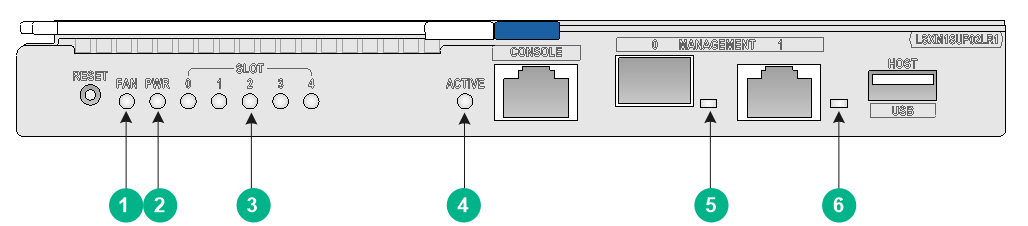
Figure1-1 LSXM1SUP02LR1 SEU LEDs
|
(1) Fan tray status LED (FAN) |
(2) Power supply status LED (PWR) |
|
(3) Module status LED (SLOT) |
(4) SEU active/standby status LED (ACTIVE) |
|
(5) SFP management Ethernet port LED |
(6) 10/100/1000BASE-T management Ethernet port LED |
|
|
NOTE: The module status LED for slot 4 is reserved for future use. |
Management Ethernet port LEDs
10/100/1000BASE-T management Ethernet port LED
The SEU provides a LED for the 10/100/1000BASE-T management Ethernet port to indicate the link status and data forwarding status of the port.
Table1-2 10/100/1000BASE-T management Ethernet port LED description
|
Status |
Description |
|
Flashing |
The port is receiving or sending data. |
|
On |
A link is present on the port. |
|
Off |
No link is present on the port. |
SFP management Ethernet port LED
The SEU provides a LED for the SFP management Ethernet port to indicate the link status and data forwarding status of the port.
Table1-3 SFP management Ethernet port LED description
|
Status |
Description |
|
Flashing |
The port is receiving or sending data. |
|
On |
A link is present on the port. |
|
Off |
No link is present on the port. |
Fan tray status LED
The SEU provides a fan tray status LED to indicate the status of the fan trays.
Table1-4 Fan tray status LED description
|
Status |
Description |
|
Steady green |
All fan trays are operating correctly. |
|
Steady red |
A fan tray has failed or no fan tray is present. |
|
Off |
The device is not powered on. |
Power supply status LED
The SEU provides a power supply status LED to indicate the status of the power supplies.
Table1-5 Power supply status LED description
|
Status |
Description |
|
Steady green |
All power supplies are operating correctly. |
|
Steady red |
A minimum of one power supply is faulty. |
|
Off |
The device is not powered on. |
Module status LEDs
The SEU provides a status LED for each module slot to indicate the status of the module.
|
|
NOTE: The SEU and interface module slot numbers are marked at the left and right sides of the slots. |
Table1-6 Module LED description
|
Status |
Description |
|
Flashing green (0.5 Hz) |
The module is operating correctly. |
|
Flashing green (4 Hz) |
The module is loading software. If the LED keeps in this state, the software versions of the device and the module do not match. |
|
Steady green |
The module is starting up. |
|
Steady red |
A high severity alarm has occurred on the module or the module is faulty. |
|
Flashing red (0.25 Hz) |
The temperature of the module is higher than the warning threshold or lower than the low-temperature threshold. |
|
Off |
The module is not present or the module is faulty. |
SEU active/standby status LED
The SEU has one ACTIVE LED to indicate the active or standby status of the SEU.
Table1-7 SEU ACTIVE LED description
|
LED status |
Description |
|
On |
The SEU is active. |
|
Off |
· The SEU is in standby status. · The SEU is faulty. Examine the module status LED for the SEU to further determine the SEU status. |
The interface modules provide one LED for each QSFP28 port to indicate the link status and data receiving/transmitting status of the QSFP28 ports.
Table1-8 QSFP28 port LED description
|
LED status |
Description |
|
Flashing |
The port is receiving or sending data. |
|
On |
A link is present on the port. |
|
Off |
No link is present on the port. |
Fan tray LEDs
A fan tray uses a RUN/ALM LED to indicate its operating status.
Table1-9 Fan tray LED description
|
Status |
Description |
|
Steady green |
The fan tray is operating correctly. |
|
Steady red |
The fan tray is faulty. |
|
Off |
The fan tray is not powered on. |
Power supply LEDs
Each power supply provides two LEDs to indicate its operating status.
Table1-10 Power supply LED description
|
LED |
Status |
Description |
|
PSR1800-56A |
||
|
AC OK |
Green |
Normal power input |
|
Off |
Abnormal or no power input |
|
|
DC OK |
Green |
Normal power output |
|
Red |
Abnormal power output |
|
|
Off |
No power output |
|
|
PSR1800-56D |
||
|
IN OK |
Green |
Normal power input |
|
Off |
Abnormal or no power input |
|
|
OUT OK |
Green |
Normal power output |
|
Red |
Abnormal power output |
|
|
Off |
No power output |
|
