- Table of Contents
-
- 06-Layer 3—IP Services Configuration Guide
- 00-Preface
- 01-ARP configuration
- 02-IP addressing configuration
- 03-DHCP configuration
- 04-DNS configuration
- 05-NAT configuration
- 06-IP forwarding basics configuration
- 07-Fast forwarding configuration
- 08-Multi-CPU packet distribution configuration
- 09-Adjacency table configuration
- 10-IRDP configuration
- 11-IP performance optimization configuration
- 12-UDP helper configuration
- 13-IPv6 basics configuration
- 14-DHCPv6 configuration
- 15-IPv6 fast forwarding configuration
- 16-AFT configuration
- 17-Tunneling configuration
- 18-GRE configuration
- 19-ADVPN configuration
- 20-WAAS configuration
- Related Documents
-
| Title | Size | Download |
|---|---|---|
| 20-WAAS configuration | 191.20 KB |
Contents
Restrictions and guidelines: WAAS configuration
Applying a WAAS policy to an interface
Configuring WAAS to operate in asymmetric mode
Configuring DRE optimization parameters
Configuring the TFO blacklist autodiscovery feature
Configuring UDP log message compression or decompression
Restoring predefined WAAS settings
Display and maintenance commands for WAAS
Example: Applying the predefined WAAS policy
Example: Configuring a user-defined WAAS policy
Example: Configuring UDP log message compression and decompression
Configuring WAAS
About WAAS
The Wide Area Application Services (WAAS) feature is a set of services that can optimize WAN traffic. WAAS solves WAN issues such as high delay and low bandwidth by using optimization services. WAAS provides the following optimization services:
· Transport Flow Optimization (TFO).
· Data Redundancy Elimination (DRE).
· Lempel-Ziv compression (LZ compression).
TFO
TFO optimizes TCP traffic without modifying packet header information. TFO uses the following optimization methods:
· Slow start optimization.
· Increased buffering.
· Congestion algorithm optimization.
· Selective acknowledgement.
Slow start optimization
The initial congestion window size for TCP slow start is one TCP segment. During slow start, TCP doubles the congestion window size for each received ACK that acknowledges new data. In this manner, the congestion window will reach an appropriate value by examining the congestion status. In a WAN environment, the congestion window takes a long time to reach an appropriate size because of high delay.
Slow start optimization shortens the slow start process by increasing the initial congestion window size.
Increased buffering
TCP has a maximum buffer size of 64 KB. After the sender sends 64 KB data, it must wait for an ACK from the receiver before continuing to send data. This mechanism wastes bandwidth on a WAN link.
Increased buffering increases the TCP buffer size to a maximum of 16384 KB. This improves link efficiency.
Congestion algorithm optimization
TCP uses the congestion window to control congestion. The window size indicates the size of data that can be sent out before an ACK is received. The window size changes with the congestion status. The greater the window size, the faster the data rate. A higher data rate more likely causes congestion. The smaller the window size, the lower the data rate. A lower data rate causes low link efficiency.
Congestion algorithm optimization achieves a trade-off between the data rate and congestion by selecting the optimum window size.
Selective acknowledgement
TCP uses a cumulative acknowledgement scheme. This scheme forces the sender to either wait a roundtrip time to know each lost packet, or to unnecessarily retransmit segments that have been correctly received. When multiple nonconsecutive segments are lost, this scheme reduces overall TCP throughput.
Selective acknowledgement (SACK) allows the receiver to inform the sender of all segments that have arrived successfully. The sender retransmits only the segments that have been lost.
DRE
DRE reduces the size of transmitted data by replacing repeated data blocks with shorter indexes. A WAAS device synchronizes its data dictionary to its peer devices. A data dictionary stores mappings between repeated data blocks and indexes.
Replacing repeated data blocks with indexes is called DRE compression. Replacing indexes with repeated data blocks is called DRE decompression.
DRE compression process
DRE compresses data in the following process:
1. The sending WAAS device caches TCP data and sends a large data block to the DRE module.
2. The DRE module divides the large data block into non-overlapping data blocks.
¡ For a repeated data block, the DRE module performs the following operations:
- Replaces the data block with its index and creates an MD5 digest for the data block.
- Sends the index and MD5 digest to the peer.
¡ For a non-repeated data block, the DRE module performs the following operations:
- Creates an index for the data block and adds it to the local data dictionary.
- Creates an MD5 digest for the data block and sends the data block, index, and MD5 digest to the peer.
To improve calculation speed and efficiency, DRE uses a sliding window mechanism to segment data and detect data redundancy. This mechanism detects repeated data blocks by using a fixed-size window to compare the original data byte by byte with data blocks in the dictionary.
DRE decompression process
DRE decompresses data in the following process:
1. The receiving WAAS device reconstructs the original data.
¡ For an index, the device replaces the index with its data block after querying the data dictionary.
If the query fails, the decompression fails, and the receiving WAAS device waits for the peer to retransmit the data.
¡ For an index and a data block, the device creates an entry for them and adds the entry to the local data dictionary.
2. The receiving WAAS device calculates an MD5 digest for the original data and compares the calculated MD5 digest with the MD5 digest in the packet.
¡ If the two MD5 digests are the same, the decompression succeeds.
¡ If the two MD5 digests are different, the decompression fails, and the receiving WAAS device waits for the peer to retransmit the data.
LZ compression
LZ compression is a lossless compression algorithm that uses a compression dictionary to replace repeated data in the same message. The compression dictionary is carried in the compression result. The sending device uses the sliding window technology to detect repeated data.
Compared with DRE, LZ compression has a lower compression ratio. LZ compression does not require synchronization of compression dictionaries between the local and peer devices. This reduces memory consumption.
Protocols and standards
· RFC 1323, TCP Extensions for High Performance
· RFC 3390, Increasing TCP's Initial Window
· RFC 2581, TCP Congestion Control
· RFC 2018, TCP Selective Acknowledgment Options
· RFC 3042, Enhancing TCP's Loss Recovery Using Limited Transmit
· RFC 2582, The NewReno Modification to TCP's Fast Recovery Algorithm
Restrictions and guidelines: WAAS configuration
For the WAAS feature to work correctly, make sure fast forwarding load sharing is disabled. For information about fast forwarding load sharing, see Layer 3—IP Services Configuration Guide.
WAAS tasks at a glance
To configure WAAS, perform the following tasks:
3. Applying a WAAS policy to an interface
4. (Optional.) Configuring WAAS to operate in asymmetric mode
5. (Optional.) Configuring TFO parameters
6. (Optional.) Configuring the TFO blacklist autodiscovery feature
7. (Optional.) Configuring DRE optimization parameters
8. (Optional.) Configuring UDP log message compression or decompression
9. (Optional.) Restoring predefined WAAS settings
10. (Optional.) Deleting all WAAS settings
Configuring a WAAS class
1. Enter system view.
system-view
2. Create a WAAS class and enter WAAS class view.
waas class class-name
By default, only predefined WAAS classes exist.
3. Configure a match criterion.
match [ match-id ] tcp { any | destination | source } [ ip-address ipv4-address [ mask-length | mask ] | ipv6-address ipv6-address [ prefix-length ] ] [ port port-list ]
Configuring a WAAS policy
About this task
To configure a WAAS policy, perform the following tasks:
1. Create a WAAS policy.
2. Specify a WAAS class for the WAAS policy.
3. Configure actions for the WAAS class.
You can configure the following actions for a WAAS class:
· Optimization actions—Optimize matching TCP traffic by using TFO alone, or by using TFO with any combination of DRE and LZ compression.
· Passthrough action—Allows matching TCP traffic to pass through unoptimized.
Restrictions and guidelines
For an optimization action to take effect, you must enable the corresponding optimization feature.
As a best practice, configure a WAAS policy by modifying the predefined WAAS policy.
Procedure
1. Enter system view.
system-view
2. Create a WAAS policy and enter WAAS policy view.
waas policy policy-name
By default, a predefined WAAS policy named waas_default exists.
3. Specify a WAAS class and enter WAAS policy class view.
class class-name [ insert-before existing_class ]
By default, no WAAS class is specified.
4. Configure optimization actions or the passthrough action.
¡ optimize tfo [ dre | lz ] *
¡ passthrough
By default, no action is configured.
5. Return to system view.
quit
6. Enable DRE.
waas tfo optimize dre
By default, DRE is enabled.
7. Enable LZ compression.
waas tfo optimize lz
By default, LZ compression is enabled.
Applying a WAAS policy to an interface
About this task
Apply a WAAS policy to an interface that connects to the WAN. The device optimizes or passes through the traffic entering and leaving the WAN according to the configured policy. If the incoming and outgoing interfaces of the traffic are both connected to the WAN, the traffic is not optimized.
Restrictions and guidelines
A WAAS policy can be applied to multiple interfaces. Only one WAAS policy can be applied to an interface.
Procedure
1. Enter system view.
system-view
2. Enter interface view.
interface interface-type interface-number
3. Apply a WAAS policy to the interface.
waas apply policy [ policy-name ]
By default, no WAAS policy is applied to an interface.
Configuring WAAS to operate in asymmetric mode
About this task
If the device sends and receives packets on the same interface, the device should operate in symmetric mode. Perform this task if the device sends and receives packets on different interfaces.
Procedure
1. Enter system view.
system-view
2. Configure WAAS to operate in asymmetric mode.
waas asymmetric
By default, WAAS operates in symmetric mode.
Configuring TFO parameters
About this task
The congestion window size changes with the congestion status and transmission speed. An appropriate initial congestion window size can quickly restore the network to its full transmission capacity after congestion occurs.
After you enable TFO keepalives, the system starts the 2-hour TCP keepalive timer. If the local device does not send or receive any data when the timer expires, it sends a keepalive to the peer to maintain the connection.
The receiving buffer size specifies the size of data that can be received. It affects network throughput.
Different network performance requirements require different TCP congestion control algorithms. Selecting a proper TCP congestion control algorithm enables a network to quickly recover to the maximum transmission capacity.
After the maximum number of concurrent connections is reached, WAAS does not optimize traffic for newly established connections.
Procedure
1. Enter system view.
system-view
2. Set the initial congestion window size.
waas tfo base-congestion-window segments
The default setting is two segments.
3. Enable TFO keepalives.
waas tfo keepalive
By default, TFO keepalives are enabled.
4. Set the receiving buffer size.
waas tfo receive-buffer buffer-size
The default setting is 64 KB.
5. Specify a TCP congestion control algorithm for the WAN side.
waas tfo congestion-method { bic | reno }
By default, WAAS uses BIC as the TCP congestion control algorithm on the WAN side.
6. Set the maximum number of concurrent connections.
waas tfo connect-limit limit
The default setting is 10000.
Configuring DRE optimization parameters
About this task
You can tune the following DRE optimization parameters:
· DRE match offset step—The higher the step level, the lower the match precision. As a best practice, use a higher-level offset step on high-speed links to improve match efficiency. Use a lower-level offset step on low-speed links to ensure match precision.
· Aging time for entries in the data dictionary—The device polls all data dictionary entries and deletes the entries that are not hit within the aging time. If the number of data dictionary entries reaches the limit, the device no longer creates new entries.
The amount of time used by the device to poll all data dictionary entries depends on the number of data dictionary entries on the device.
Procedure
1. Enter system view.
system-view
2. Set the DRE match offset step.
waas dre offset-step { general | fast | fastest | normal }
The default setting is normal.
The following DRE match offset step levels are listed from high to low:
¡ fastest
¡ fast
¡ general
¡ normal
3. Set the aging time for data dictionary entries.
waas dre cache aging minutes
By default, data dictionary entries are not aged out, and the newly created entry overwrites the oldest entry if the number of data dictionary entries reaches the limit.
Configuring the TFO blacklist autodiscovery feature
About this task
This feature automatically discovers servers that cannot receive TCP packets with options and adds the server IP addresses and port numbers to a blacklist. The system automatically removes blacklist entries after a user-configured aging time.
During the 3-way handshake, the local device determines that the TCP connection attempt fails if either of the following situations occurs:
· The peer device does not respond within the specified time period.
· The peer device closes the TCP connection.
Procedure
1. Enter system view.
system-view
2. Enable the TFO blacklist autodiscovery feature.
waas tfo auto-discovery blacklist enable
By default, the TFO blacklist autodiscovery feature is disabled.
3. Set the aging time for blacklist entries.
waas tfo auto-discovery blacklist hold-time minutes
The default setting is 5 minutes.
Configuring UDP log message compression or decompression
About this task
You configure UDP log message compression on the upstream device and configure UDP log message decompression on the downstream device. The upstream device compresses packets and forwards them to the downstream device. The downstream device decompresses the received packets and then forwards them.
Restrictions and guidelines
Fragmented packets and packets with the Options field are not compressed or decompressed.
You can enable UDP log message compression or decompression for the same destination IP address, but not both.
Procedure
1. Enter system view.
system-view
2. Enable UDP log message compression or decompression.
waas udp { compress [ max max-number ] | decompress }
By default, UDP log message compression and decompression is disabled.
3. Specify the destination IP address and destination port number of UDP log messages to be compressed or decompressed.
waas udp ip ip-address port port-number
By default, no destination IP address and destination port number are specified.
Restoring predefined WAAS settings
About this task
This feature allows you to restore the predefined WAAS policy and WAAS classes to their configurations when the WAAS process starts for the first time.
Restrictions and guidelines
To successfully restore predefined WAAS settings, make sure none of the interfaces has a WAAS policy applied.
Procedure
1. Enter system view.
system-view
2. Restore predefined WAAS settings.
waas config restore-default
Deleting all WAAS settings
About this task
This feature allows you to delete all configuration data and running data for WAAS and to exit the WAAS process.
Procedure
1. Enter system view.
system-view
2. Delete all WAAS settings.
waas config remove-all
Display and maintenance commands for WAAS
Execute display commands in any view and reset commands in user view.
|
Task |
Command |
|
Display WAAS class configuration. |
display waas class [ class-name ] |
|
Display WAAS policy configuration. |
display waas policy [ policy-name ] |
|
Display WAAS session information. |
In standalone mode: display waas session { ipv4 | ipv6 } [ client-ip client-ip ] [ client-port client-port ] [ server-ip server-ip ] [ server-port server-port ] [ peer-id peer-id ] [ verbose ] In IRF mode: display waas session { ipv4 | ipv6 } [ client-ip client-ip ] [ client-port client-port ] [ server-ip server-ip ] [ server-port server-port ] [ peer-id peer-id ] [ verbose ] [ slot slot-number ] |
|
Display DRE statistics. |
In standalone mode: display waas statistics dre [ peer peer-id ] In IRF mode: display waas statistics dre [ peer peer-id ] [ slot slot-number ] |
|
Display UDP log message compression statistics. |
display waas statistics udp compress |
|
Display the global WAAS status. |
display waas status |
|
Display autodiscovered blacklist information. |
display waas tfo auto-discovery blacklist { ipv4 | ipv6 } In IRF mode: display waas tfo auto-discovery blacklist { ipv4 | ipv6 } [ slot slot-number ] |
|
Clear the DRE data dictionary. |
reset waas cache dre [ peer-id peer-id ] |
|
Clear DRE statistics. |
reset waas statistics dre [ peer-id peer-id ] |
|
Clear UDP log message compression statistics. |
reset waas statistics udp compress |
|
Clear all blacklist entries. |
reset waas tfo auto-discovery blacklist |
WAAS configuration examples
Example: Applying the predefined WAAS policy
Network configuration
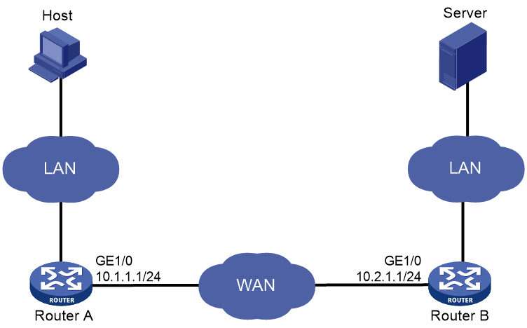
As shown in Figure 1, apply the predefined WAAS policy on Router A and Router B.
The host downloads data from the server. Examine the optimization effect by comparing DRE statistics for the first download and second download.
· For the first download, both WAAS devices create data dictionary entries and Router A sends both indexes and metadata.
· For the second download, Router A replaces repeated data with indexes.

Procedure
1. Configure IP addresses for interfaces. (Details not shown.)
2. Configure routing protocols to ensure connectivity. (Details not shown.)
3. Disable fast forwarding load sharing:
# Disable fast forwarding load sharing on Router A.
<RouterA> system-view
[RouterA] undo ip fast-forwarding load-sharing
# Disable fast forwarding load sharing on Router B.
<RouterB> system-view
[RouterB] undo ip fast-forwarding load-sharing
4. Apply the predefined WAAS policy to GigabitEthernet 1/0/1 on Router A.
[RouterA] interface gigabitethernet 1/0/1
[RouterA-GigabitEthernet1/0/1] waas apply policy
[RouterA-GigabitEthernet1/0/1] quit
[RouterA] quit
5. Apply the predefined WAAS policy to GigabitEthernet 1/0/1 on Router B.
[RouterB] interface gigabitethernet 1/0/1
[RouterB-GigabitEthernet1/0/1] waas apply policy
6. Download a test file of 14 MB from the server to the host.
7. Clear DRE statistics on Router A.
<RouterA> reset waas statistic dre
8. Download the same file from the server to the host.
Verifying the configuration
# After the first download, display DRE statistics on Router A.
<RouterA> display waas statistic dre
Peer-ID: cc3e-5fd8-5158
Peer version: 1.0
Cache in storage: 12710912 bytes
Index number: 49652
Age: 00 weeks, 00 days, 00 hours, 00 minutes, 35 seconds
Total connections: 1
Active connections: 0
Encode Statistics
Dre msgs: 2
Bytes in: 286 bytes
Bytes out: 318 bytes
Bypass bytes: 0 bytes
Bytes Matched: 0 bytes
Space saved: -11%
Average latency: 0 usec
Decode Statistics
Dre msgs: 57050
Bytes in: 14038391 bytes
Bytes out: 14079375 bytes
Bypass bytes: 0 bytes
Space saved: 0%
Average latency: 0 usec
# After the second download, display DRE statistics on Router A.
<RouterA> display waas statistic dre
Peer-ID: cc3e-5fd8-5158
Peer version: 1.0
Cache in storage: 12851200 bytes
Index number: 50200
Age: 00 weeks, 00 days, 00 hours, 2 minutes, 56 seconds
Total connections: 1
Active connections: 0
Encode Statistics
Dre msgs: 2
Bytes in: 286 bytes
Bytes out: 60 bytes
Bypass bytes: 0 bytes
Bytes Matched: 256 bytes
Space saved: 79%
Average latency: 0 usec
Decode Statistics
Dre msgs: 62791
Bytes in: 2618457 bytes
Bytes out: 13972208 bytes
Bypass bytes: 0 bytes
Space saved: 81%
Average latency: 0 usec
In the second download, the number of received bytes for decompression is much more smaller, and the download speed is much faster.
Example: Configuring a user-defined WAAS policy
Network configuration
As shown in Figure 2, configure and apply a user-defined WAAS policy on Router A and Router B.
The host downloads data from the server. Examine the optimization effect by comparing DRE statistics for the first download and second download.
· For the first download, both WAAS devices need to create data dictionary entries and Router A sends both indexes and metadata.
· For the second download, Router A replaces repeated data with indexes.
Procedure
1. Configure IP addresses for interfaces. (Details not shown.)
2. Configure routing protocols to ensure connectivity. (Details not shown.)
3. Disable fast forwarding load sharing:
# Disable fast forwarding load sharing on Router A.
<RouterA> system-view
[RouterA] undo ip fast-forwarding load-sharing
# Disable fast forwarding load sharing on Router B.
<RouterB> system-view
[RouterB] undo ip fast-forwarding load-sharing
4. Configure WAAS classes:
# Create a WAAS class named c1 on Router A, and configure the WAAS class to match any TCP packets.
[RouterA] waas class c1
[RouterA-waasclass-c1] match 1 tcp any
[RouterA-waasclass-c1] quit
# Create a WAAS class named c1 on Router B, and configure the WAAS class to match any TCP packets.
[RouterB] waas class c1
[RouterB-waasclass-c1] match tcp any
[RouterB-waasclass-c1] quit
5. Configure WAAS policies:
# Create a WAAS policy named p1 on Router A, and specify WAAS class c1. Configure TFO, DRE, and LZ optimization actions for the WAAS class.
[RouterA] waas policy p1
[RouterA-waaspolicy-p1] class c1
[RouterA-waaspolicy-p1-c1] optimize tfo dre lz
[RouterA-waaspolicy-p1-c1] quit
[RouterA-waaspolicy-p1] quit
# Create a WAAS policy named p1 on Router B, and specify WAAS class c1. Configure TFO, DRE, and LZ optimization actions for the WAAS class.
[RouterB] waas policy p1
[RouterB-waaspolicy-p1] class c1
[RouterB-waaspolicy-p1-c1] optimize tfo dre lz
[RouterB-waaspolicy-p1-c1] quit
[RouterB-waaspolicy-p1] quit
6. Apply WAAS policies:
# Apply WAAS policy p1 to GigabitEthernet 1/0/1 on Router A.
<RouterA> system-view
[RouterA] interface gigabitethernet 1/0/1
[RouterA-GigabitEthernet1/0/1] waas apply policy
[RouterA-GigabitEthernet1/0/1] quit
[RouterA] quit
# Apply WAAS policy p1 to GigabitEthernet 1/0/1 on Router B.
[RouterB] interface gigabitethernet 1/0/1
[RouterB-GigabitEthernet1/0/1] waas apply policy p1
[RouterB-GigabitEthernet1/0/1] quit
[RouterB] quit
7. Download a test file of 14 MB from the server to the host.
8. Clear DRE statistics on Router A.
<RouterA> reset waas statistic dre
9. Download the same file from the server to the host.
Verifying the configuration
# After the first download, display DRE statistics on Router A.
<RouterA> display waas statistic dre
Peer-ID: cc3e-5fd8-5158
Peer version: 1.0
Cache in storage: 12718592 bytes
Index number: 49682
Age: 00 weeks, 00 days, 00 hours, 00 minutes, 35 seconds
Total connections: 1
Active connections: 0
Encode Statistics
Dre msgs: 2
Bytes in: 286 bytes
Bytes out: 318 bytes
Bypass bytes: 0 bytes
Bytes Matched: 0 bytes
Space saved: -11%
Average latency: 0 usec
Decode Statistics
Dre msgs: 56959
Bytes in: 13999244 bytes
Bytes out: 14055291 bytes
Bypass bytes: 0 bytes
Space saved: 0%
Average latency: 0 usec
# After the second download, display DRE statistics on Router A.
<RouterA> display waas statistic dre
Peer-ID: cc3e-5fd8-5158
Peer version: 1.0
Cache in storage: 12857856 bytes
Index number: 50226
Age: 00 weeks, 00 days, 00 hours, 2 minutes, 02 seconds
Total connections: 1
Active connections: 0
Encode Statistics
Dre msgs: 2
Bytes in: 286 bytes
Bytes out: 60 bytes
Bypass bytes: 0 bytes
Bytes Matched: 256 bytes
Space saved: 79%
Average latency: 0 usec
Decode Statistics
Dre msgs: 62687
Bytes in: 2592183 bytes
Bytes out: 13972208 bytes
Bypass bytes: 0 bytes
Space saved: 81%
Average latency: 0 usec
In the second download, the number of received bytes for decompression is much more smaller, and the download speed is much faster.
Example: Configuring UDP log message compression and decompression
Network configuration
As shown in Figure 3, the IP address of the server is 172.16.105.48.
Configure UDP log message compression and decompression to meet the following requirements:
· Router A compresses log messages from the host and then forwards them to Router B.
· Router B decompresses the log messages from Router A and then forwards them to the server.

Procedure
1. Configure IP addresses for interfaces. (Details not shown.)
2. Configure routing protocols to ensure connectivity. (Details not shown.)
3. Disable fast forwarding load sharing:
# Disable fast forwarding load sharing on Router A.
<RouterA> system-view
[RouterA] undo ip fast-forwarding load-sharing
# Disable fast forwarding load sharing on Router B.
<RouterB> system-view
[RouterB] undo ip fast-forwarding load-sharing
4. Configure UDP log message compression and decompression:
# Enable UDP log message compression on Router A.
<RouterA> system-view
[RouterA] waas udp compress
# Specify that UDP log messages with destination IP address 172.16.105.48 and destination port number 5000 are compressed.
[RouterA] waas udp ip 172.16.105.48 port 5000
# Enable UDP log message decompression on Router B.
<RouterB> system-view
[RouterB] waas udp decompress
# Specify that UDP log messages with destination IP address 172.16.105.48 and destination port number 5000 are decompressed.
[RouterB] waas udp ip 172.16.105.48 port 5000
Verifying the configuration
# Display UDP log message compression statistics on Router A.
[RouterA] display waas statistic udp compress
Bytes in : 30106991182
Bytes out : 375556018
Saved bandwidth ratio : 98.75%
Compressed packet ratio : 100.00%
The output shows that the bandwidth is saved by 98.75% through log message compression.