- Table of Contents
-
- 09-High Availability Configuration Guide
- 00-Preface
- 01-Hot backup configuration
- 02-RBM configuration
- 03-VRRP configuration
- 04-BFD configuration
- 05-Track configuration
- 06-Reth interface and redundancy group configuration
- 07-Failover group configuration
- 08-Interface collaboration configuration
- 09-Interface backup configuration
- 10-Monitor Link configuration
- 11-Smart Link configuration
- 12-Process placement configuration
- Related Documents
-
| Title | Size | Download |
|---|---|---|
| 01-Hot backup configuration | 839.56 KB |
Restrictions and guidelines: Hot backup configuration
Operating modes of RBM hot backup
NAT on an RBM hot backup system
About NAT on an RBM hot backup system
RBM hot backup support for SSL VPN
Prerequisites for RBM hot backup configuration
RBM hot backup configuration flow
RBM hot backup configuration examples
Example: Configuring an RBM hot backup system in active/standby mode in collaboration with VRRP
Example: Configuring an RBM hot backup system in dual-active mode in collaboration with VRRP
Example: Configuring NAT on an RBM hot backup system in dual-active mode in collaboration with VRRP
IRF hot backup deployment schemes
IRF hot backup in active/standby mode with redundancy groups
IRF hot backup in dual-active mode with redundancy groups
IRF hot backup in dual-active mode with link aggregations
Comparison between the deployment schemes
Prerequisites for IRF hot backup configuration
IRF hot backup configuration flow
IRF hot backup configuration examples
Example: Configuring an IRF hot backup system in active/standby mode with one redundancy group
Example: Configuring an IRF hot backup system in dual-active mode with two redundancy groups
Hot backup overview
Hot backup is a device-level HA solution. It enables two devices to back up each other dynamically to ensure user service continuity upon failure of one of the devices.
Application scenario
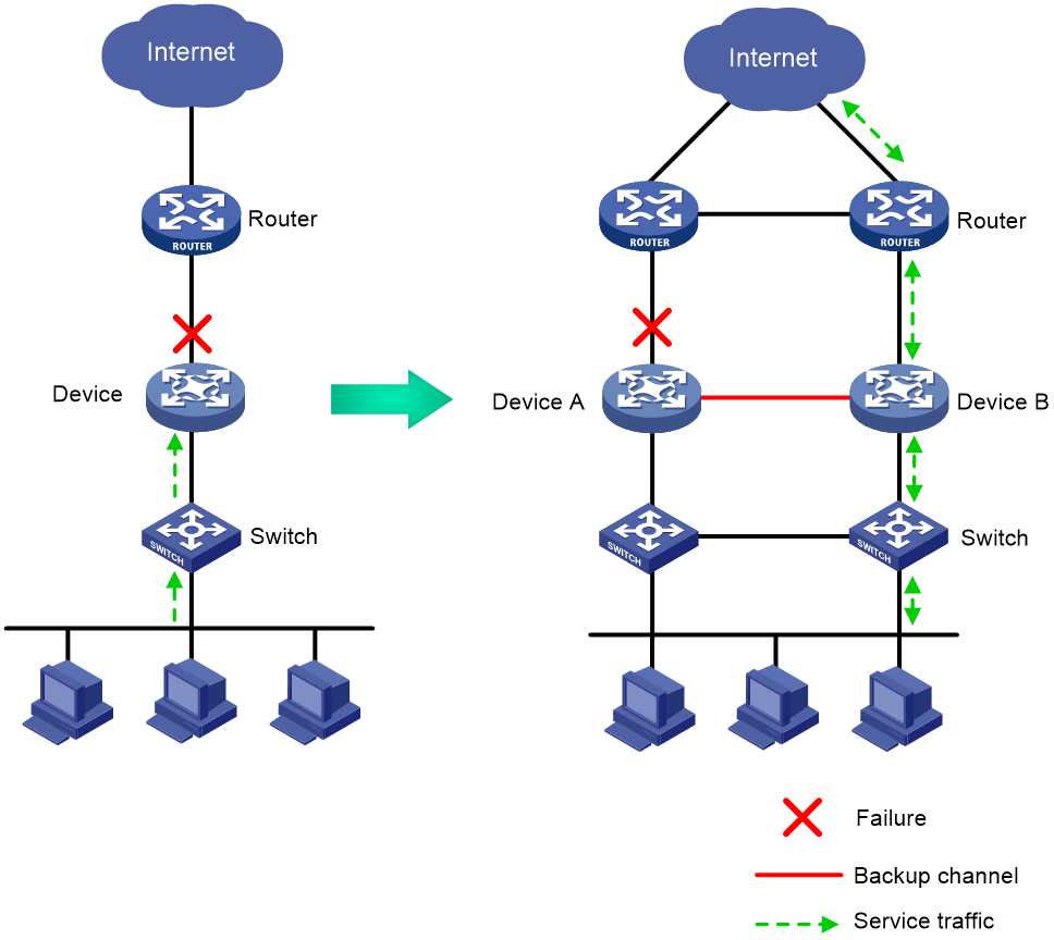
As shown in Figure 1, typically redundant egress devices are deployed at the border between the external and internal networks to prevent a single point of failure from interrupting traffic forwarding. When one egress device fails, traffic is switched to a different path.
Figure 1 Hot backup network model
Operating modes of hot backup
Hot backup supports the active/standby and dual-active modes.
Active/standby mode
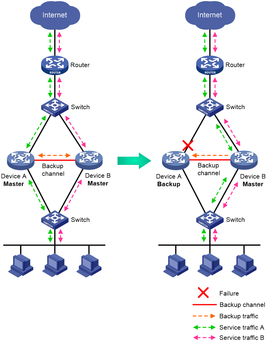
In active/standby mode, one device acts as the master to process services, and the other device stands by as a backup, as shown in Figure 2. When an interface or link on the master fails or when the master fails, the backup takes over the master role to process services.
Figure 2 Active/standby mode of hot backup

Dual-active mode
In dual-active mode, both devices process services to increase capability of the hot backup system, as shown in Figure 3. When one device fails, its traffic is switched to the other device for forwarding.
Figure 3 Dual-active mode of hot backup
Hot backup deployment schemes
Hot backup supports the following deployment schemes:
· RBM hot backup—Uses remote backup management (RBM) in collaboration with Virtual Router Redundancy Protocol (VRRP) or routing protocols.
· IRF hot backup—Relies on Intelligent Resilient Framework (IRF), Ethernet link aggregation, Reth interfaces, and redundancy groups.
Restrictions and guidelines: Hot backup configuration
You cannot use RBM hot backup and IRF hot backup together.
A hot backup system can contain a maximum of two devices.
To ensure that the traffic size is within the processing capability of one device upon failure of the other device, make sure the throughput of each device does not exceed 50% of its capability.
Configuring RBM hot backup
About RBM hot backup
RBM hot backup uses RBM in collaboration with VRRP or routing protocols to set up a hot backup system. RBM backs up service entries and configuration between the member devices and controls traffic switchover to ensure symmetric forwarding of flows.
For more information about VRRP, see "Configuring VRRP." For more information about RBM, see "Configuring RBM." For more information about routing protocols, see Layer 3—IP Routing Configuration Guide.
ARP and MAC learning in VRRP
When the members of a VRRP group receive an ARP request for the group's virtual IP address, the master replies with the group's virtual MAC address. This allows the upstream and downstream Layer 2 devices and hosts to learn the virtual MAC address.
Operating modes of RBM hot backup
RBM hot backup supports the active/standby and dual-active modes.
Active/standby mode
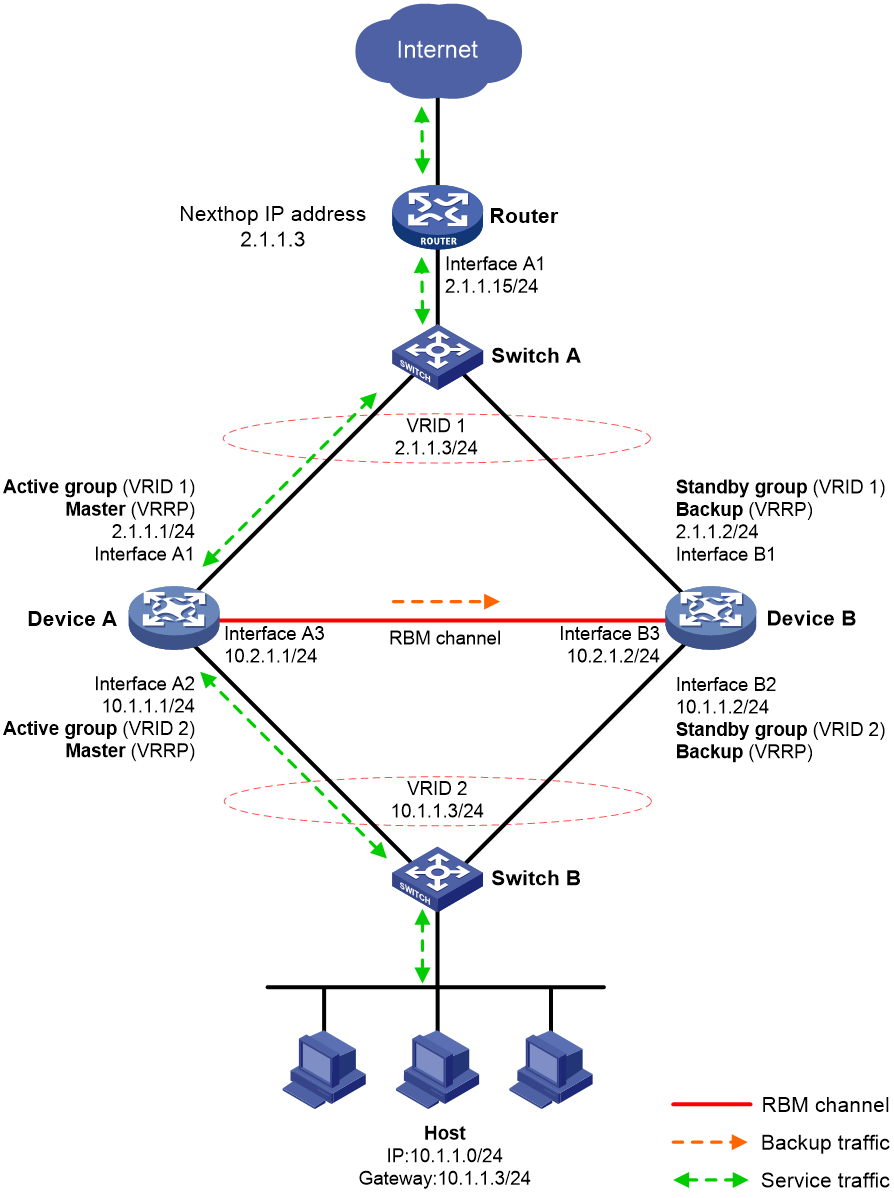
Figure 4 shows a typical model of an RBM hot backup system operating in active/standby mode. The hot backup system is directly connected to the upstream and downstream Layer 2 switches by Layer 3 interfaces, and RBM collaborates with VRRP. To use the active/standby mode, perform the following tasks:
· Establish RBM channels between Device A and Device B.
· On Device A and Device B, create uplink VRRP group 1 and downlink VRRP group 2 and associate them with RBM.
· On Device A, associate VRRP group 1 and VRRP group 2 with the VRRP active group. On Device B, associate VRRP group 1 and VRRP group 2 with the VRRP standby group.
· On Device A and Device B, specify the IP address of Interface A1 on the router (2.1.1.15) as the next hop of the route to the Internet.
· On the router, specify the virtual IP address of VRRP group 1 (2.1.1.3) as the next hop of the route to the host's subnet.
· On the host, specify the virtual IP address of VRRP group 2 (10.1.1.3) as the default gateway.
· On Switch A, assign the interfaces attached to the router, Device A, and Device B to the same VLAN.
· On Switch B, assign the interfaces attached to the host, Device A, and Device B to the same VLAN.
Figure 4 RBM hot backup system operating in active/standby mode
The following shows how traffic is forwarded when the host accesses the Internet in Figure 4:
1. The host identifies that the destination IP address is on a different subnet and sends an ARP request to obtain the MAC address of the default gateway. In this example, the host does not have the ARP entry for the default gateway.
2. Switch B broadcasts the ARP request and learns the MAC address of the host.
3. Device A and Device B receives the ARP request, and Device A (master) replies with the virtual MAC address of VRRP group 2.
4. Switch B learns the MAC address entry for the virtual MAC address of VRRP group 2 and forwards the ARP reply to the host.
5. The host learns the virtual MAC address and sends the packets destined for the Internet to the default gateway.
6. Switch B forwards the packets to Device A (master). The traffic of the host will be processed and forwarded by Device A as long as it is the master.
7. Device A does not have the ARP entry for the next hop of the route to the Internet and sends an ARP request to obtain the MAC address of the next hop. In the ARP request, the source MAC address is the virtual MAC address of VRRP group 1.
8. Switch A and the router then perform typical forwarding and ARP and MAC address learning.
The forwarding process for the traffic sent from the Internet to the host is similar to the above process.
Dual-active mode
Figure 5 shows a typical model of an RBM hot backup system operating in dual-active mode. The hot backup system is directly connected to the upstream and downstream Layer 2 switches by Layer 3 interfaces, and RBM collaborates with VRRP. To use the dual-active mode, perform the following tasks:
· Establish RBM channels between Device A and Device B.
· On Device A and Device B, create two uplink VRRP groups and two downlink VRRP groups.
· Create VRRP group 3 and VRRP group 4 on the downlink interfaces of Device A and Device B.
· On Device A, associate VRRP group 1 and VRRP group 3 with the VRRP active group, and associate VRRP group 2 and VRRP group 4 with the VRRP standby group.
· On Device B, associate VRRP group 1 and VRRP group 3 with the VRRP standby group, and associate VRRP group 2 and VRRP group 4 with the VRRP active group.
· On Device A and Device B, specify the IP address of Interface A1 on the router (2.1.1.15) as the next hop of the route to the Internet.
· On the router, configure routes as follows:
¡ Specify the virtual IP address of VRRP group 1 (2.1.1.3) as the next hop of the route to Host A's subnet.
¡ Specify the virtual IP address of VRRP group 2 (2.1.1.4) as the next hop of the route to Host B's subnet.
· On Host A, specify the virtual IP address of VRRP group 3 (10.1.1.3) as the default gateway.
· On Host B, specify the virtual IP address of VRRP group 4 (10.1.1.4) as the default gateway.
· On Switch A, assign the interfaces attached to the router, Device A, and Device B to the same VLAN.
· On Switch B, assign the interfaces attached to the hosts, Device A, and Device B to the same VLAN.
Figure 5 RBM hot backup system operating in dual-active mode
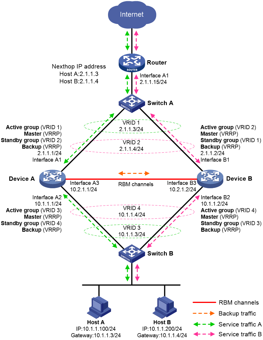
As shown in Figure 5, the traffic of Host A and Host B is distributed to Device A and Device B, respectively. The traffic forwarding process is similar to that in active/standby mode.
NAT on an RBM hot backup system
For NAT to operate correctly on an RBM hot backup system, you must associate NAT features with the VRRP groups. For example, when you use dynamic NAT, static NAT, NAT server, or NAT444, you must associate the feature with the VRRP groups. For more information about NAT features, see NAT Configuration Guide.
NAT features have similar mechanisms, and the operating mode of the RBM hot backup system does not change the IP address translation process. This section uses dynamic NAT on an RBM hot backup system in active/standby mode to explain how NAT works on an RBM hot backup system.
About NAT on an RBM hot backup system
When receiving an ARP request with a target IP address that belongs to the subnet of the IP address of a NAT interface, a NAT device replies with the MAC address of the NAT interface.
As shown in Figure 6, dynamic NAT is configured on an RBM hot backup system that is operating in active/standby mode. If dynamic NAT is not associated with any VRRP group, the devices process the traffic as follows when the host accesses the Internet:
1. When receiving the packets sent by the host, Device A translates the source IP address into a public IP address in the NAT address group and forwards the packets to the router. In this example, the public IP address is in the same subnet as the virtual IP address of uplink VRRP group 1.
2. The router receives the return packets and broadcasts an ARP request for the destination public IP address.
3. Device A and Device B receive the ARP request and reply with the MAC address of their respective uplink interface because they have the same NAT address group configuration.
4. The router might send the return packets to the uplink interface of Device A or Device B, which affects service continuity.
For the router to learn the virtual MAC address of the uplink VRRP group, you must associate NAT features with the VRRP group.
Figure 6 NAT not associated with a VRRP group
Traffic forwarding process
The master in a VRRP group relies with the virtual MAC address of the VRRP group to an ARP request if the following requirements are met:
· NAT features are associated with the VRRP group.
· The target IP address belongs to the subnet that contains the IP address of a NAT interface.
As shown in Figure 7, dynamic NAT is configured on an RBM hot backup system that is operating in active/standby mode. If NAT is associated with the uplink VRRP group, the devices process the traffic as follows when the host accesses the Internet:
1. When receiving the packets sent by the host, Device A translates the source IP address into a public IP address in the NAT address group and forwards the packets to the router. In this example, the public IP address is in the same subnet as the virtual IP address of uplink VRRP group 1.
2. The router receives the return packets and broadcasts an ARP request for the destination public IP address.
3. Device A and Device B receive the ARP request, and Device A (master) replies with the virtual MAC addresses of the uplink VRRP group.
4. Router A sends the return packets to Device A.
Figure 7 NAT on an RBM hot backup system
For more information about VRRP group association with dynamic NAT, static NAT, NAT server, and NAT444, see Layer 3—IP Services Configuration Guide.
RBM hot backup support for SSL VPN
To back up SSL VPN data, you must use the sslvpn rbm-port command to establish a data backup channel for SSL VPN on the RBM hot backup system. For more information about the data backup channel and SSL VPN configuration, see VPN Configuration Guide.
An RBM hot backup system supports SSL VPN only when it is operating in active/standby mode.
Prerequisites for RBM hot backup configuration
Before you configure RBM hot backup, verify that the following hardware and software settings are the same on the member devices of the hot backup system:
· Device model.
· Software version.
· IRF member ID.
· Interface for setting up the control channel.
· Interface for setting up the data channel.
· Security zone configuration on the interfaces with the same slot number.
· Location, number, and type of service modules.
· Location, number, and type of interface modules.
Please finish the configuration of the features for which RBM hot backup does not synchronize configuration, such as the interface and routing features.
RBM hot backup configuration flow
Figure 8 shows the configuration flow for RBM hot backup.
Figure 8 RBM hot backup configuration flow chart
RBM hot backup configuration examples
Example: Configuring an RBM hot backup system in active/standby mode in collaboration with VRRP
Network configuration
As shown in Figure 9, set up an RBM hot backup system at the border between the Internet and the internal network of an enterprise to ensure service continuity.
· Configure RBM to collaborate with VRRP.
· Configure the hot backup system to operate in active/standby mode.
· Configure Device A and Device B as the primary device and the secondary device, respectively.

Procedure
1. Verify that Device A and Device B meet the requirements described in "Prerequisites for RBM hot backup configuration."
2. Configure Device A:
# Assign IP addresses to interfaces and configure routes, security zones, zone pairs, and interzone policies. Make sure the network connections are available. (Details not shown.)
# Configure interzone policies to permit communication between security zones RBM-zone and Local. This allows Device A and Device B to set up the RBM channels. (Details not shown.)
# Configure interzone policies to permit communication between security zones Untrust and Local and between security zones Trust and Local. This allows Device A and Device B to exchange VRRP packets and elect the master when the RBM channels are unavailable. (Details not shown.)
# Specify 10.2.1.2 as the destination IP address of the RBM control channel. In this example, the default port number 60064 is used.
<DeviceA> system-view
[DeviceA] remote-backup group
[DeviceA-remote-backup-group] remote-ip 10.2.1.2
# Specify 10.2.1.1 as the source IP address of the RBM control channel.
[DeviceA-remote-backup-group] local-ip 10.2.1.1
# Set up an RBM data channel on GigabitEthernet 1/2/5/3. In this example, the data channel and the control channel share a physical link.
[DeviceA-remote-backup-group] data-channel interface gigabitethernet 1/2/5/3
# Assign the primary role to Device A in the remote backup group.
[DeviceA-remote-backup-group] device-role primary
# Set the operating mode of the hot backup system to active/standby.
[DeviceA-remote-backup-group] undo backup-mode
# Enable RBM hot backup.
[DeviceA-remote-backup-group] hot-backup enable
# Enable automatic configuration synchronization.
[DeviceA-remote-backup-group] configuration auto-sync enable
# Set the configuration consistency check interval to 12 hours.
[DeviceA-remote-backup-group] configuration sync-check interval 12
[DeviceA-remote-backup-group] quit
# Create VRRP group 1 on GigabitEthernet 1/2/5/1, set its virtual IP address to 2.1.1.3, and associate it with the VRRP active group.
[DeviceA] interface gigabitethernet 1/2/5/1
[DeviceA-GigabitEthernet1/2/5/1] vrrp vrid 1 virtual-ip 2.1.1.3 active
[DeviceA-GigabitEthernet1/2/5/1] quit
# Create VRRP group 2 on GigabitEthernet 1/2/5/2, set its virtual IP address to 10.1.1.3, and associate it with the VRRP active group.
[DeviceA] interface gigabitethernet 1/2/5/2
[DeviceA-GigabitEthernet1/2/5/2] vrrp vrid 2 virtual-ip 10.1.1.3 active
[DeviceA-GigabitEthernet1/2/5/2] quit
3. Configure Device B:
# Assign IP addresses to interfaces and configure routes, security zones, zone pairs, and interzone policies. Make sure the network connections are available. (Details not shown.)
# Configure interzone policies to permit communication between security zones RBM-zone and Local. This allows Device A and Device B to set up the RBM channels. (Details not shown.)
# Configure interzone policies to permit communication between security zones Untrust and Local and between security zones Trust and Local. This allows Device A and Device B to exchange VRRP packets and elect the master when the RBM channels are unavailable. (Details not shown.)
# Specify 10.2.1.1 as the destination IP address of the RBM control channel. In this example, the default port number 60064 is used.
<DeviceB> system-view
[DeviceB] remote-backup group
[DeviceB-remote-backup-group] remote-ip 10.2.1.1
# Specify 10.2.1.2 as the source IP address of the RBM control channel.
[DeviceB-remote-backup-group] local 10.2.1.2
# Set up an RBM data channel on GigabitEthernet 1/2/5/3. In this example, the data channel and the control channel share a physical link.
[DeviceB-remote-backup-group] data-channel interface gigabitethernet 1/2/5/3
# Assign the secondary role to Device B in the remote backup group.
[DeviceB-remote-backup-group] device-role secondary
# Set the operating mode of the hot backup system to active/standby.
[DeviceB-remote-backup-group] undo backup-mode
# Enable RBM hot backup.
[DeviceB-remote-backup-group] hot-backup enable
# Enable automatic configuration synchronization.
[DeviceB-remote-backup-group] configuration auto-sync enable
# Set the configuration consistency check interval to 12 hours.
[DeviceB-remote-backup-group] configuration sync-check interval 12
[DeviceB-remote-backup-group] quit
# Create VRRP group 1 on GigabitEthernet 1/2/5/1, set its virtual IP address to 2.1.1.3, and associate it with the VRRP standby group.
[DeviceB] interface gigabitethernet 1/2/5/1
[DeviceB-GigabitEthernet1/2/5/1] vrrp vrid 1 virtual-ip 2.1.1.3 standby
[DeviceB-GigabitEthernet1/2/5/1] quit
# Create VRRP group 2 on GigabitEthernet 1/2/5/2, set its virtual IP address to 10.1.1.3, and associate it with the VRRP standby group.
[DeviceB] interface gigabitethernet 1/2/5/2
[DeviceB-GigabitEthernet1/2/5/2] vrrp vrid 2 virtual-ip 10.1.1.3 standby
[DeviceB-GigabitEthernet1/2/5/2] quit
4. Configure Switch A:
|
|
NOTE: This step only provides the brief configuration procedure. |
# Create VLAN 10.
# Configure the interfaces attached to the hot backup system and the router to operate at Layer 2. Assign them to VLAN 10 as access interfaces.
5. Configure Switch B:
|
|
NOTE: This step only provides the brief configuration procedure. |
# Create VLAN 10.
# Configure the interfaces attached to the hot backup system and the host to operate at Layer 2. Assign them to VLAN 10 as access interfaces.
6. Configure the router:
|
|
NOTE: This step only provides the brief configuration procedure. |
# Assign 2.1.1.15/24 to GigabitEthernet 1/0/1.
# Configure routes as follows:
¡ Specify 2.1.1.3 (virtual IP address of VRRP group 1) as the next hop of the route to the internal network.
¡ Specify the IP address of peer interface attached to the traffic outgoing interface as the next hop of the route to the Internet.
7. Configure security services on Device A (primary). For more information about the security services can be backed up by RBM, see "Configuring RBM."
8. On the host, specify 10.1.1.3 (virtual IP address of VRRP group 2) as the default gateway. (Details not shown.)
Verifying the configuration
1. Verify the configuration on Device A:
# Verify that the RBM channels have been set up.
[DeviceA] display remote-backup-group status
Remote backup group information:
Backup mode: Active/standby
Device role: Primary
Local IP: 10.2.1.1
Remote IP: 10.2.1.2 Destination port: 60064
Control channel status: Connected
Hot backup status: Enabled
Auto configuration synchronization: Enable
Configuration consistency check interval: 12 hour
Delay-time: 0 min
# Verify that Device A is the master in all VRRP groups.
[DeviceA] display vrrp
IPv4 Virtual Router Information:
Running mode : Standard
RBM control channel is established
VRRP active group status : Master
VRRP standby group status: Master
Total number of virtual routers : 2
Interface VRID State Running Adver Auth Virtual
Pri Timer Type IP
---------------------------------------------------------------------
GE1/2/5/1 1 Master 100 100 None 2.1.1.3
GE1/2/5/2 2 Master 100 100 None 10.1.1.3
# Enable logging for the interzone policy that permits communication between security zones Trust and Untrust. Verity that Device A generates log messages when the host communicates with the Internet. (Details not shown.)
2. Verify the configuration on Device B:
# Verify that the RBM channels have been set up.
[DeviceB] display remote-backup-group status
Remote backup group information:
Backup mode: Active/standby
Device role: Secondary
Local IP: 10.2.1.2
Remote IP: 10.2.1.1 Destination port: 60064
Control channel status: Connected
Hot backup status: Enabled
Auto configuration synchronization: Enable
Configuration consistency check interval: 12 hour
Delay-time: 0 min
# Verify that Device A is the backup in all VRRP groups.
[DeviceB] display vrrp
IPv4 Virtual Router Information:
Running mode : Standard
RBM control channel is established
VRRP active group status : Backup
VRRP standby group status: Backup
Total number of virtual routers : 2
Interface VRID State Running Adver Auth Virtual
Pri Timer Type IP
---------------------------------------------------------------------
GE1/2/5/1 1 Backup 100 100 None 2.1.1.3
GE1/2/5/2 2 Backup 100 100 None 10.1.1.3
# Enable logging for the interzone policy that permits communication between security zones Trust and Untrust. Verity that Device B does not generate log messages when the host communicates with the Internet. (Details not shown.)
Example: Configuring an RBM hot backup system in dual-active mode in collaboration with VRRP
Network configuration
As shown in Figure 10, set up an RBM hot backup system at the border between the Internet and the internal network of an enterprise to ensure service continuity.
· Configure RBM to collaborate with VRRP.
· Configure the hot backup system to operate in dual-active mode.
· Configure Device A and Device B to load share traffic.

Procedure
1. Verify that Device A and Device B meet the requirements described in "Prerequisites for RBM hot backup configuration."
2. Configure Device A:
# Assign IP addresses to interfaces and configure routes, security zones, zone pairs, and interzone policies. Make sure the network connections are available. (Details not shown.)
# Configure interzone policies to permit communication between security zones RBM-zone and Local. This allows Device A and Device B to set up the RBM channels. (Details not shown.)
# Configure interzone policies to permit communication between security zones Untrust and Local and between security zones Trust and Local. This allows Device A and Device B to exchange VRRP packets and elect the master when the RBM channels are unavailable. (Details not shown.)
# Specify 10.2.1.2 as the destination IP address of the RBM control channel. In this example, the default port number 60064 is used.
<DeviceA> system-view
[DeviceA] remote-backup group
[DeviceA-remote-backup-group] remote-ip 10.2.1.2
# Specify 10.2.1.1 as the source IP address of the RBM control channel.
[DeviceA-remote-backup-group] local-ip 10.2.1.1
# Set up an RBM data channel on GigabitEthernet 1/2/5/3. In this example, the data channel and the control channel share a physical link.
[DeviceB-remote-backup-group] data-channel interface gigabitethernet 1/2/5/3
# Assign the primary role to Device A in the remote backup group.
[DeviceA-remote-backup-group] device-role primary
# Set the operating mode of the hot backup system to dual-active.
[DeviceA-remote-backup-group] backup-mode dual-active
# Enable RBM hot backup.
[DeviceA-remote-backup-group] hot-backup enable
# Enable automatic configuration synchronization.
[DeviceA-remote-backup-group] configuration auto-sync enable
# Set the configuration consistency check interval to 12 hours.
[DeviceA-remote-backup-group] configuration sync-check interval 12
# Enable traffic switchover upon failure recovery, and set the switchover delay to 1 minute.
[DeviceA-remote-backup-group] delay-time 1
[DeviceA-remote-backup-group] quit
# Create VRRP group 1 on GigabitEthernet 1/2/5/1, set its virtual IP address to 2.1.1.3, and associate it with the VRRP active group.
[DeviceA] interface gigabitethernet 1/2/5/1
[DeviceA-GigabitEthernet1/2/5/1] vrrp vrid 1 virtual-ip 2.1.1.3 active
# Create VRRP group 2 on GigabitEthernet 1/2/5/1, set its virtual IP address to 2.1.1.4, and associate it with the VRRP standby group.
[DeviceA-GigabitEthernet1/2/5/1] vrrp vrid 2 virtual-ip 2.1.1.4 standby
[DeviceA-GigabitEthernet1/2/5/1] quit
# Create VRRP group 3 on GigabitEthernet 1/2/5/2, set its virtual IP address to 10.1.1.3, and associate it with the VRRP active group.
[DeviceA] interface gigabitethernet 1/2/5/2
[DeviceA-GigabitEthernet1/2/5/2] vrrp vrid 3 virtual-ip 10.1.1.3 active
# Create VRRP group 4 on GigabitEthernet 1/2/5/2, set its virtual IP address to 10.1.1.4, and associate it with the VRRP standby group.
[DeviceA-GigabitEthernet1/2/5/2] vrrp vrid 4 virtual-ip 10.1.1.4 standby
[DeviceA-GigabitEthernet1/2/5/2] quit
3. Configure Device B:
# Assign IP addresses to interfaces and configure routes, security zones, zone pairs, and interzone policies. Make sure the network connections are available. (Details not shown.)
# Configure interzone policies to permit communication between security zones RBM-zone and Local. This allows Device A and Device B to set up the RBM channels. (Details not shown.)
# Configure interzone policies to permit communication between security zones Untrust and Local and between security zones Trust and Local. This allows Device A and Device B to exchange VRRP packets and elect the master when the RBM channels are unavailable. (Details not shown.)
# Specify 10.2.1.1 as the destination IP address of the RBM control channel. In this example, the default port number 60064 is used.
<DeviceB> system-view
[DeviceB] remote-backup group
[DeviceB-remote-backup-group] remote-ip 10.2.1.1
# Specify 10.2.1.2 as the source IP address of the RBM control channel.
[DeviceB-remote-backup-group] local-ip 10.2.1.2
# Set up an RBM data channel on GigabitEthernet 1/2/5/3. In this example, the data channel and the control channel share a physical link.
[DeviceB-remote-backup-group] data-channel interface gigabitethernet 1/2/5/3
# Assign the secondary role to Device B in the remote backup group.
[DeviceB-remote-backup-group] device-role secondary
# Set the operating mode of the hot backup system to dual-active.
[DeviceB-remote-backup-group] backup-mode dual-active
# Enable RBM hot backup.
[DeviceB-remote-backup-group] hot-backup enable
# Enable automatic configuration synchronization.
[DeviceB-remote-backup-group] configuration auto-sync enable
# Set the configuration consistency check interval to 12 hours.
[DeviceB-remote-backup-group] configuration sync-check interval 12
# Enable traffic switchover upon failure recovery, and set the switchover delay to 1 minute.
[DeviceB-remote-backup-group] delay-time 1
[DeviceB-remote-backup-group] quit
# Create VRRP group 1 on GigabitEthernet 1/2/5/1, set its virtual IP address to 2.1.1.3, and associate it with the VRRP standby group.
[DeviceB] interface gigabitethernet 1/2/5/1
[DeviceB-GigabitEthernet1/2/5/1] vrrp vrid 1 virtual-ip 2.1.1.3 standby
# Create VRRP group 2 on GigabitEthernet 1/2/5/1, set its virtual IP address to 2.1.1.4, and associate it with the VRRP active group.
[DeviceB-GigabitEthernet1/2/5/1] vrrp vrid 2 virtual-ip 2.1.1.4 active
[DeviceB-GigabitEthernet1/2/5/1] quit
# Create VRRP group 3 on GigabitEthernet 1/2/5/2, set its virtual IP address to 10.1.1.3, and associate it with the VRRP standby group.
[DeviceB] interface gigabitethernet 1/2/5/2
[DeviceB-GigabitEthernet1/2/5/2] vrrp vrid 3 virtual-ip 10.1.1.3 standby
# Create VRRP group 4 on GigabitEthernet 1/2/5/2, set its virtual IP address to 10.1.1.4, and associate it with the VRRP active group.
[DeviceB-GigabitEthernet1/2/5/2] vrrp vrid 4 virtual-ip 10.1.1.4 active
[DeviceB-GigabitEthernet1/2/5/2] quit
4. Configure Switch A:
|
|
NOTE: This step only provides the brief configuration procedure. |
# Create VLAN 10.
# Configure the interfaces attached to the hot backup system and the router to operate at Layer 2. Assign them to VLAN 10 as access interfaces.
5. Configure Switch B:
|
|
NOTE: This step only provides the brief configuration procedure. |
# Create VLAN 10.
# Configure the interfaces attached to the hot backup system and the host to operate at Layer 2. Assign them to VLAN 10 as access interfaces.
6. Configure the router:
|
|
NOTE: This step only provides the brief configuration procedure. |
# Assign 2.1.1.15/24 to GigabitEthernet 1/0/1.
# Configure routes as follows:
¡ Specify 2.1.1.3 (virtual IP address of VRRP group 1) as the next hop of the routes to some subnets of the internal network. Specify 2.1.1.4 (virtual IP address of VRRP group 2) as the next hop of the routes to the other subnets of the internal network.
¡ Specify the IP address of the peer interface attached to the traffic outgoing interface as the next hop of the route to the Internet.
7. Configure security services on Device A (primary). For more information about the security services can be backed up by RBM, see "Configuring RBM."
8. On some hosts, specify 10.1.1.3 (virtual IP address of VRRP group 3) as the default gateway. On the other hosts, specify 10.1.1.4 (virtual IP address of VRRP group 4) as the default gateway. (Details not shown.)
Verifying the configuration
1. Verify the configuration on Device A:
# # Verify that the RBM channels have been set up.
[DeviceA] display remote-backup-group status
Remote backup group information:
Backup mode: Dual-active
Device role: Primary
Local IP: 10.2.1.1
Remote IP: 10.2.1.2 Destination port: 60064
Control channel status: Connected
Hot backup status: Enabled
Auto configuration synchronization: Enable
Configuration consistency check interval: 12 hour
Delay-time: 1 min
# Verify that Device A is the master in VRRP groups 1 and 3 and the backup in VRRP groups 2 and 4.
[DeviceA] display vrrp
IPv4 Virtual Router Information:
Running mode : Standard
RBM control channel is established
VRRP active group status : Master
VRRP standby group status: Backup
Total number of virtual routers : 2
Interface VRID State Running Adver Auth Virtual
Pri Timer Type IP
---------------------------------------------------------------------
GE1/2/5/1 1 Master 100 100 None 2.1.1.3
GE1/2/5/1 2 Backup 100 100 None 2.1.1.4
GE1/2/5/2 3 Master 100 100 None 10.1.1.3
GE1/2/5/2 4 Backup 100 100 None 10.1.1.4
# Enable logging for the interzone policy that permits communication between security zones Trust and Untrust. Verity that Device A generates log messages when a host for which Device A forwards traffic communicates with the Internet. Verity that Device A does not generate log messages when a host for which Device B forwards traffic communicates with the Internet. (Details not shown.)
2. Verify the configuration on Device B:
# Verify that the RBM channels have been set up.
[DeviceB] display remote-backup-group status
Remote backup group information:
Backup mode: Dual-active
Device role: Secondary
Local IP: 10.2.1.2
Remote IP: 10.2.1.1 Destination port: 60064
Control channel status: Connected
Hot backup status: Enabled
Auto configuration synchronization: Enable
Configuration consistency check interval: 12 hour
Delay-time: 1 min
# Verify that Device B is the master in VRRP groups 2 and 4 and the backup in VRRP groups 1 and 3.
[DeviceB] display vrrp
IPv4 Virtual Router Information:
Running mode : Standard
RBM control channel is established
VRRP active group status : Master
VRRP standby group status: Backup
Total number of virtual routers : 2
Interface VRID State Running Adver Auth Virtual
Pri Timer Type IP
---------------------------------------------------------------------
GE1/2/5/1 1 Backup 100 100 None 2.1.1.3
GE1/2/5/1 2 Master 100 100 None 2.1.1.4
GE1/2/5/2 3 Backup 100 100 None 10.1.1.3
GE1/2/5/2 4 Master 100 100 None 10.1.1.4
# Enable logging for the interzone policy that permits communication between security zones Trust and Untrust. Verity that Device B generates log messages when a host for which Device B forwards traffic communicates with the Internet. Verity that Device B does not generate log messages when a host for which Device A forwards traffic communicates with the Internet. (Details not shown.)
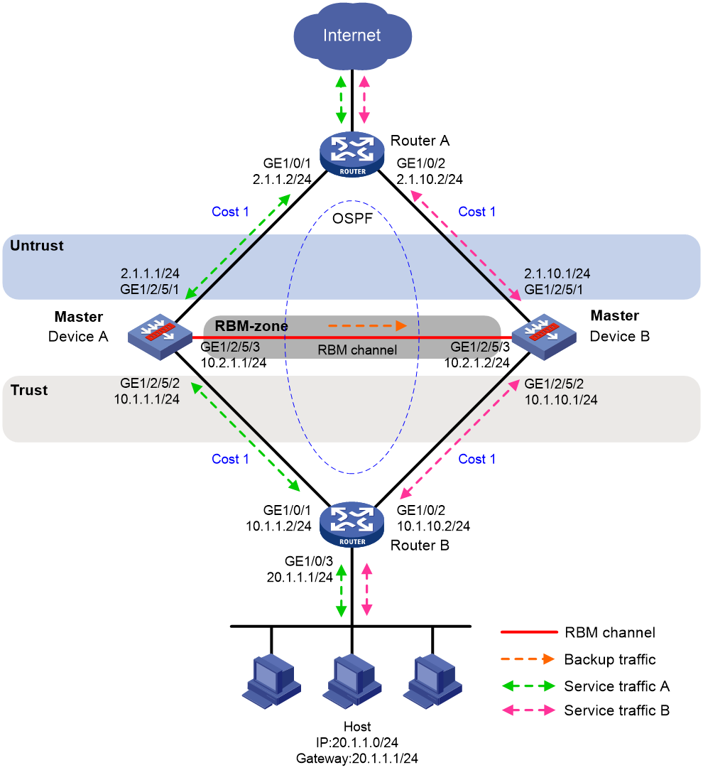
Example: Configuring an RBM hot backup system in active/standby mode in collaboration with a routing protocol
Network configuration
As shown in Figure 11, set up an RBM hot backup system at the border between the Internet and the internal network of an enterprise to ensure service continuity.
· Configure RBM to collaborate with OSPF.
· Configure the hot backup system to operate in active/standby mode.
· Configure Device A and Device B as the primary device and the secondary device, respectively.
Procedure
1. Verify that Device A and Device B meet the requirements described in "Prerequisites for RBM hot backup configuration."
2. Configure Device A:
# Assign IP addresses to interfaces and configure routes, security zones, zone pairs, and interzone policies. Make sure the network connections are available. (Details not shown.)
# Configure interzone policies to permit communication between security zones RBM-zone and Local. This allows Device A and Device B to set up the RBM channels. (Details not shown.)
# Configure interzone policies to permit communication between security zones Untrust and Local and between security zones Trust and Local. This allows Device A and Device B to exchange OSPF protocol packets (Details not shown.)
# Configure OSPF. Use the default OSPF link cost configuration.
<DeviceA> system-view
[DeviceA] router id 2.1.1.1
[DeviceA] ospf
[DeviceA-ospf-1] area 0
[DeviceA-ospf-1-area-0.0.0.0] network 2.1.1.0 0.0.0.255
[DeviceA-ospf-1-area-0.0.0.0] network 10.1.1.0 0.0.0.255
[DeviceA-ospf-1-area-0.0.0.0] quit
[DeviceA-ospf-1] quit
# Associate track entry 1 with the link state of GigabitEthernet 1/2/5/1.
[DeviceA] track 1 interface gigabitethernet 1/2/5/1
[DeviceA-track-1] quit
# Associate track entry 2 with the link state of GigabitEthernet 1/2/5/2.
[DeviceA] track 2 interface gigabitethernet 1/2/5/2
[DeviceA-track-2] quit
# Specify 10.2.1.2 as the destination IP address of the RBM control channel. In this example, the default port number 60064 is used.
[DeviceA] remote-backup group
[DeviceA-remote-backup-group] remote-ip 10.2.1.2
# Specify 10.2.1.1 as the source IP address of the RBM control channel.
[DeviceA-remote-backup-group] local-ip 10.2.1.1
# Set up an RBM data channel on GigabitEthernet 1/2/5/3. In this example, the data channel and the control channel share a physical link.
[DeviceA-remote-backup-group] data-channel interface gigabitethernet 1/2/5/3
# Assign the primary role to Device A in the remote backup group.
[DeviceA-remote-backup-group] device-role primary
# Set the operating mode of the hot backup system to active/standby.
[DeviceA-remote-backup-group] undo backup-mode
# Enable RBM hot backup.
[DeviceA-remote-backup-group] hot-backup enable
# Enable automatic configuration synchronization.
[DeviceA-remote-backup-group] configuration auto-sync enable
# Set the configuration consistency check interval to 12 hours.
[DeviceA-remote-backup-group] configuration sync-check interval 12
# Configure RBM to change the link costs advertised in OSPF routes to 1.
[DeviceA-remote-backup-group] adjust-cost ospf enable absolute 1
# Configure RBM to monitor the status of track entry 1 and track entry 2.
[DeviceA-remote-backup-group] track 1
[DeviceA-remote-backup-group] track 2
[DeviceA-remote-backup-group] quit
3. Configure Device B:
# Assign IP addresses to interfaces and configure routes, security zones, zone pairs, and interzone policies. Make sure the network connections are available. (Details not shown.)
# Configure interzone policies to permit communication between security zones RBM-zone and Local. This allows Device A and Device B to set up the RBM channels. (Details not shown.)
# Configure interzone policies to permit communication between security zones Untrust and Local and between security zones Trust and Local. This allows Device A and Device B to exchange OSPF protocol packets. (Details not shown.)
# Configure OSPF. Use the default OSPF link cost configuration.
<DeviceB> system-view
[DeviceB] router id 2.1.10.1
[DeviceB] ospf
[DeviceB-ospf-1] area 0
[DeviceB-ospf-1-area-0.0.0.0] network 2.1.10.0 0.0.0.255
[DeviceB-ospf-1-area-0.0.0.0] network 10.1.10.0 0.0.0.255
[DeviceB-ospf-1-area-0.0.0.0] quit
[DeviceB-ospf-1] quit
# Associate track entry 1 with the link state of GigabitEthernet 1/2/5/1.
[DeviceB] track 1 interface gigabitethernet 1/2/5/1
[DeviceB-track-1] quit
# Associate track entry 2 with the link state of GigabitEthernet 1/2/5/2.
[DeviceB] track 2 interface gigabitethernet 1/2/5/2
[DeviceB-track-2] quit
# Specify 10.2.1.1 as the destination IP address of the RBM control channel. In this example, the default port number 60064 is used.
[DeviceB] remote-backup group
[DeviceB-remote-backup-group] remote-ip 10.2.1.1
# Specify 10.2.1.2 as the source IP address of the RBM control channel.
[DeviceB-remote-backup-group] local 10.2.1.2
# Set up an RBM data channel on GigabitEthernet 1/2/5/3. In this example, the data channel and the control channel share a physical link.
[DeviceB-remote-backup-group] data-channel interface gigabitethernet 1/2/5/3
# Assign the secondary role to Device B in the remote backup group.
[DeviceB-remote-backup-group] device-role secondary
# Set the operating mode of the hot backup system to active/standby.
[DeviceB-remote-backup-group] undo backup-mode
# Enable RBM hot backup.
[DeviceB-remote-backup-group] hot-backup enable
# Enable automatic configuration synchronization.
[DeviceB-remote-backup-group] configuration auto-sync enable
# Set the configuration consistency check interval to 12 hours.
[DeviceB-remote-backup-group] configuration sync-check interval 12
# Configure RBM to change the link costs advertised in OSPF routes to 6000.
[DeviceB-remote-backup-group] adjust-cost ospf enable absolute 6000
# Configure RBM to monitor the status of track entry 1 and track entry 2.
[DeviceB-remote-backup-group] track 1
[DeviceB-remote-backup-group] track 2
[DeviceB-remote-backup-group] quit
4. Configure Router A:
|
|
NOTE: This step only provides the brief configuration procedure. |
# Assign 2.1.1.2/24 to GigabitEthernet 1/0/1.
# Assign 2.1.10.2/24 to GigabitEthernet 1/0/2.
# Configure OSPF for Device A, Device B, and the routers to have Layer 3 reachability.
5. Configure Router B:
|
|
NOTE: This step only provides the brief configuration procedure. |
# Assign 10.1.1.2/24 to GigabitEthernet 1/0/1.
# Assign 10.1.10.2/24 to GigabitEthernet 1/0/2.
# Configure OSPF for Device A, Device B, and the routers to have Layer 3 reachability.
6. Configure security services on Device A (primary). For more information about the security services can be backed up by RBM, see "Configuring RBM."
7. On the host, specify 20.1.1.1 as the default gateway. (Details not shown.)
Verifying the configuration
1. Verify the configuration on Device A:
# Verify that the RBM channels have been set up.
[DeviceA] display remote-backup-group status
Remote backup group information:
Backup mode: Active/standby
Device role: Primary
Local IP: 10.2.1.1
Remote IP: 10.2.1.2 Destination port: 60064
Control channel status: Connected
Hot backup status: Enabled
Auto configuration synchronization: Enable
Configuration consistency check interval: 12 hour
Delay-time: 0 min
# Verify that the OSPF routes advertised by Device A include a smaller link cost than that advertised by Device B.
[DeviceA] display ospf interface
OSPF Process 1 with Router ID 2.1.1.1
Interfaces
Area: 0.0.0.0
IP Address Type State Cost Pri DR BDR
2.1.1.1 Broadcast BDR 1 1 2.1.1.2 2.1.1.1
10.1.1.1 Broadcast DR 1 1 10.1.1.1 10.1.1.2
2. Verify the configuration on Device B:
# Verify that the RBM channels have been set up.
[DeviceB] display remote-backup-group status
Remote backup group information:
Backup mode: Active/standby
Device role: Secondary
Local IP: 10.2.1.2
Remote IP: 10.2.1.1 Destination port: 60064
Control channel status: Connected
Hot backup status: Enabled
Auto configuration synchronization: Enable
Configuration consistency check interval: 12 hour
Delay-time: 0 min
# Verify that the OSPF routes advertised by Device B include a larger link cost than that advertised by Device A.
[DeviceB] display ospf interface
OSPF Process 1 with Router ID 2.1.10.1
Interfaces
Area: 0.0.0.0
IP Address Type State Cost Pri DR BDR
2.1.10.1 Broadcast BDR 6000 1 2.1.10.2 2.1.10.1
10.1.10.1 Broadcast BDR 6000 1 10.1.10.2 10.1.10.1
Example: Configuring an RBM hot backup system in dual-active mode in collaboration with a routing protocol
Network configuration
As shown in Figure 12, set up an RBM hot backup system at the border between the Internet and the internal network of an enterprise to ensure service continuity.
· Configure RBM to collaborate with OSPF.
· Configure the hot backup system to operate in dual-active mode.
· Configure Device A and Device B to load share traffic.
Procedure
1. Verify that Device A and Device B meet the requirements described in "Prerequisites for RBM hot backup configuration."
2. Configure Device A:
# Assign IP addresses to interfaces and configure routes, security zones, zone pairs, and interzone policies. Make sure the network connections are available. (Details not shown.)
# Configure interzone policies to permit communication between security zones RBM-zone and Local. This allows Device A and Device B to set up the RBM channels. (Details not shown.)
# Configure interzone policies to permit communication between security zones Untrust and Local and between security zones Trust and Local. This allows Device A and Device B to exchange OSPF protocol packets. (Details not shown.)
# Configure OSPF. Use the default OSPF link cost configuration.
<DeviceA> system-view
[DeviceA] router id 2.1.1.1
[DeviceA] ospf
[DeviceA-ospf-1] area 0
[DeviceA-ospf-1-area-0.0.0.0] network 2.1.1.0 0.0.0.255
[DeviceA-ospf-1-area-0.0.0.0] network 10.1.1.0 0.0.0.255
[DeviceA-ospf-1-area-0.0.0.0] quit
[DeviceA-ospf-1] quit
# Associate track entry 1 with the link state of GigabitEthernet 1/2/5/1.
[DeviceA] track 1 interface gigabitethernet 1/2/5/1
[DeviceA-track-1] quit
# Associate track entry 2 with the link state of GigabitEthernet 1/2/5/2.
[DeviceA] track 2 interface gigabitethernet 1/2/5/2
[DeviceA-track-2] quit
# Specify 10.2.1.2 as the destination IP address of the RBM control channel. In this example, the default port number 60064 is used.
[DeviceA] remote-backup group
[DeviceA-remote-backup-group] remote-ip 10.2.1.2
# Specify 10.2.1.1 as the source IP address of the RBM control channel.
[DeviceA-remote-backup-group] local-ip 10.2.1.1
# Set up an RBM data channel on GigabitEthernet 1/2/5/3. In this example, the data channel and the control channel share a physical link.
[DeviceB-remote-backup-group] data-channel interface gigabitethernet 1/2/5/3
# Assign the primary role to Device A in the remote backup group.
[DeviceA-remote-backup-group] device-role primary
# Set the operating mode of the hot backup system to dual-active.
[DeviceA-remote-backup-group] backup-mode dual-active
# Enable RBM hot backup.
[DeviceA-remote-backup-group] hot-backup enable
# Enable automatic configuration synchronization.
[DeviceA-remote-backup-group] configuration auto-sync enable
# Set the configuration consistency check interval to 12 hours.
[DeviceA-remote-backup-group] configuration sync-check interval 12
# Enable traffic switchover upon failure recovery, and set the switchover delay to 1 minute.
[DeviceA-remote-backup-group] delay-time 1
# Configure RBM to change the link costs advertised in OSPF routes to 1.
[DeviceA-remote-backup-group] adjust-cost ospf enable absolute 1
# Configure RBM to monitor the status of track entry 1 and track entry 2.
[DeviceA-remote-backup-group] track 1
[DeviceA-remote-backup-group] track 2
[DeviceA-remote-backup-group] quit
3. Configure Device B:
# Assign IP addresses to interfaces and configure routes, security zones, zone pairs, and interzone policies. Make sure the network connections are available. (Details not shown.)
# Configure interzone policies to permit communication between security zones RBM-zone and Local. This allows Device A and Device B to set up the RBM channels. (Details not shown.)
# Configure interzone policies to permit communication between security zones Untrust and Local and between security zones Trust and Local. This allows Device A and Device B to exchange OSPF protocol packets. (Details not shown.)
# Configure OSPF. Use the default OSPF link cost configuration.
<DeviceB> system-view
[DeviceB] router id 2.1.10.1
[DeviceB] ospf
[DeviceB-ospf-1] area 0
[DeviceB-ospf-1-area-0.0.0.0] network 2.1.10.0 0.0.0.255
[DeviceB-ospf-1-area-0.0.0.0] network 10.1.10.0 0.0.0.255
[DeviceB-ospf-1-area-0.0.0.0] quit
[DeviceB-ospf-1] quit
# Associate track entry 1 with the link state of GigabitEthernet 1/2/5/1.
[DeviceB] track 1 interface gigabitethernet 1/2/5/1
[DeviceB-track-1] quit
# Associate track entry 2 with the link state of GigabitEthernet 1/2/5/2.
[DeviceB] track 2 interface gigabitethernet 1/2/5/2
[DeviceB-track-2] quit
# Specify 10.2.1.1 as the destination IP address of the RBM control channel. In this example, the default port number 60064 is used.
[DeviceB] remote-backup group
[DeviceB-remote-backup-group] remote-ip 10.2.1.1
# Specify 10.2.1.2 as the source IP address of the RBM control channel.
[DeviceB-remote-backup-group] local-ip 10.2.1.2
# Set up an RBM data channel on GigabitEthernet 1/2/5/3. In this example, the data channel and the control channel share a physical link.
[DeviceB-remote-backup-group] data-channel interface gigabitethernet 1/2/5/3
# Assign the secondary role to Device B in the remote backup group.
[DeviceB-remote-backup-group] device-role secondary
# Set the operating mode of the hot backup system to dual-active.
[DeviceB-remote-backup-group] backup-mode dual-active
# Enable RBM hot backup.
[DeviceB-remote-backup-group] hot-backup enable
# Enable automatic configuration synchronization.
[DeviceB-remote-backup-group] configuration auto-sync enable
# Set the configuration consistency check interval to 12 hours.
[DeviceB-remote-backup-group] configuration sync-check interval 12
# Enable traffic switchover upon failure recovery, and set the switchover delay to 1 minute.
[DeviceB-remote-backup-group] delay-time 1
# Configure RBM to change the link costs advertised in OSPF routes to 1.
[DeviceB-remote-backup-group] adjust-cost ospf enable absolute 1
# Configure RBM to monitor the status of track entry 1 and track entry 2.
[DeviceB-remote-backup-group] track 1
[DeviceB-remote-backup-group] track 2
[DeviceB-remote-backup-group] quit
4. Configure Router A:
|
|
NOTE: This step only provides the brief configuration procedure. |
# Assign 2.1.1.2/24 to GigabitEthernet 1/0/1.
# Assign 2.1.10.2/24 to GigabitEthernet 1/0/2.
# Configure OSPF for Device A, Device B, and the routers to have Layer 3 reachability.
# Configure per-flow load sharing for IP forwarding.
5. Configure Router B:
|
|
NOTE: This step only provides the brief configuration procedure. |
# Assign 10.1.1.2/24 to GigabitEthernet 1/0/1.
# Assign 10.1.10.2/24 to GigabitEthernet 1/0/2.
# Configure OSPF for Device A, Device B, and the routers to have Layer 3 reachability.
# Configure per-flow load sharing for IP forwarding.
6. Configure security services on Device A (primary). For more information about the security services can be backed up by RBM, see "Configuring RBM."
7. On the hosts, specify 20.1.1.1 as the default gateway. (Details not shown.)
Verifying the configuration
1. Verify the configuration on Device A:
# # Verify that the RBM channels have been set up.
[DeviceA] display remote-backup-group status
Remote backup group information:
Backup mode: Dual-active
Device role: Primary
Local IP: 10.2.1.1
Remote IP: 10.2.1.2 Destination port: 60064
Control channel status: Connected
Hot backup status: Enabled
Auto configuration synchronization: Enable
Configuration consistency check interval: 12 hour
Delay-time: 1 min
# Verify that the OSPF routes advertised by Device A and Device B include the same link cost.
[DeviceA] display ospf interface
OSPF Process 1 with Router ID 2.1.1.1
Interfaces
Area: 0.0.0.0
IP Address Type State Cost Pri DR BDR
2.1.1.1 Broadcast BDR 1 1 2.1.1.2 2.1.1.1
10.1.1.1 Broadcast DR 1 1 10.1.1.1 10.1.1.2
2. Verify the configuration on Device B:
# Verify that the RBM channels have been set up.
[DeviceB] display remote-backup-group status
Remote backup group information:
Backup mode: Dual-active
Device role: Secondary
Local IP: 10.2.1.2
Remote IP: 10.2.1.1 Destination port: 60064
Control channel status: Connected
Hot backup status: Enabled
Auto configuration synchronization: Enable
Configuration consistency check interval: 12 hour
Delay-time: 1 min
# Verify that the OSPF routes advertised by Device A and Device B include the same link cost.
[DeviceB] display ospf interface
OSPF Process 1 with Router ID 2.1.10.1
Interfaces
Area: 0.0.0.0
IP Address Type State Cost Pri DR BDR
2.1.10.1 Broadcast BDR 1 1 2.1.10.2 2.1.10.1
10.1.10.1 Broadcast BDR 1 1 10.1.10.2 10.1.10.1
Example: Configuring NAT on an RBM hot backup system in active/standby mode in collaboration with VRRP
Network configuration
As shown in Figure 13, set up an RBM hot backup system at the border between the Internet and the internal network of an enterprise to ensure service continuity.
· Configure RBM to collaborate with VRRP.
· Configure the hot backup system to operate in active/standby mode.
· Configure Device A and Device B as the primary device and the secondary device, respectively.
· Configure dynamic NAT to translate the private IP addresses in the internal network into public IP addresses 2.1.1.1 through 2.1.1.10.
Procedure
1. Set up the hot backup system as described in "Example: Configuring an RBM hot backup system in active/standby mode in collaboration with VRRP."
2. Configure dynamic NAT on Device A (primary):
# Create NAT address group 1 and add address range 2.1.1.5 to 2.1.1.10.
<DeviceA> system-view
[DeviceA] nat address-group 1
[DeviceA-address-group-1] address 2.1.1.5 2.1.1.10
# Associate NAT address group 1 with VRRP group 1.
[DeviceA-address-group-1] vrrp vrid 1
[DeviceA-address-group-1] quit
# Configure outbound dynamic NAT to use NAT address group 1 for address translation on GigabitEthernet 1/2/5/1.
[DeviceA] interface gigabitethernet 1/2/5/1
[DeviceA-GigabitEthernet1/2/5/1] nat outbound address-group 1
[DeviceA-GigabitEthernet1/2/5/1] quit
Verifying the configuration
# Verify that the host can communicate with the Internet. (Details not shown.)
# Verify that Device A has generated a NAT session entry.
[DeviceA] display nat session verbose
Slot 1:
Initiator:
Source IP/port: 10.1.1.10/52082
Destination IP/port: 202.38.1.10/80
DS-Lite tunnel peer: -
VPN instance/VLAN ID/Inline ID: -/-/-
Protocol: TCP(6)
Inbound interface: GigabitEthernet1/2/5/2
Source security zone: Trust
Responder:
Source IP/port: 202.38.1.10/80
Destination IP/port: 2.1.1.5/1036
DS-Lite tunnel peer: -
VPN instance/VLAN ID/Inline ID: -/-/-
Protocol: TCP(6)
Inbound interface: GigabitEthernet1/2/5/1
Source security zone: Untrust
State: TCP_ESTABLISHED
Application: HTTP
Rule ID: 2
Rule name: 3
Start time: 2019-1-29 16:16:59 TTL: 9995s
Initiator->Responder: 551 packets 32547 bytes
Responder->Initiator: 956 packets 1385514 bytes
Total sessions found: 1
Example: Configuring NAT on an RBM hot backup system in dual-active mode in collaboration with VRRP
Network configuration
As shown in Figure 14, set up an RBM hot backup system at the border between the Internet and the internal network of an enterprise to ensure service continuity.
· Configure RBM to collaborate with VRRP.
· Configure the hot backup system to operate in dual-active mode.
· Configure Device A and Device B to load share traffic.
· Configure dynamic NAT to translate the private IP addresses in the internal network into public IP addresses 2.1.1.1 through 2.1.1.10.
Procedure
1. Set up the hot backup system as described in "Example: Configuring an RBM hot backup system in dual-active mode in collaboration with VRRP".
2. Configure dynamic NAT on Device A (primary):
# Create NAT address group 1 and add address range 2.1.1.5 to 2.1.1.7.
<DeviceA> system-view
[DeviceA] nat address-group 1
[DeviceA-address-group-1] address 2.1.1.5 2.1.1.7
# Associate NAT address group 1 with VRRP group 1.
[DeviceA-address-group-1] vrrp vrid 1
[DeviceA-address-group-1] quit
# Create NAT address group 2 and add address range 2.1.1.8 to 2.1.1.10.
[DeviceA] nat address-group 2
[DeviceA-address-group-2] address 2.1.1.8 2.1.1.10
# Associate NAT address group 2 with VRRP group 2.
[DeviceA-address-group-2] vrrp vrid 2
[DeviceA-address-group-2] quit
# Configure ACL 3000 to permit packets from 10.1.1.1/25.
[DeviceA] acl advanced 3000
[DeviceA-ipv4-adv-3000] rule permit ip source 10.1.1.1 0.0.0.127
[DeviceA-ipv4-adv-3000] quit
# Configure ACL 3001 to permit packets from 10.1.1.129/25.
[DeviceA] acl advanced 3001
[DeviceA-ipv4-adv-3001] rule permit ip source 10.1.1.129 0.0.0.127
[DeviceA-ipv4-adv-3001] quit
# Configure outbound dynamic NAT on GigabitEthernet 1/2/5/1. The source IP addresses of the packets permitted by ACL 3000 are translated into the addresses in NAT address group 1. The source IP addresses of the packets permitted by ACL 3001 are translated into the addresses in NAT address group 2.
[DeviceA] interface gigabitethernet 1/2/5/1
[DeviceA-GigabitEthernet1/2/5/1] nat outbound 3000 address-group 1
[DeviceA-GigabitEthernet1/2/5/1] nat outbound 3001 address-group 2
[DeviceA-GigabitEthernet1/2/5/1] quit
Verifying the configuration
# Verify that Host 1 can communicate with the Internet. (Details not shown.)
# Verify that Device A has generated a NAT session entry.
[DeviceA] display nat session verbose
Slot 1:
Initiator:
Source IP/port: 10.1.1.100/52082
Destination IP/port: 202.38.1.10/80
DS-Lite tunnel peer: -
VPN instance/VLAN ID/Inline ID: -/-/-
Protocol: TCP(6)
Inbound interface: GigabitEthernet1/2/5/2
Source security zone: Trust
Responder:
Source IP/port: 202.38.1.10/80
Destination IP/port: 2.1.1.5/1036
DS-Lite tunnel peer: -
VPN instance/VLAN ID/Inline ID: -/-/-
Protocol: TCP(6)
Inbound interface: GigabitEthernet1/2/5/1
Source security zone: Untrust
State: TCP_ESTABLISHED
Application: HTTP
Rule ID: 2
Rule name: 3
Start time: 2019-1-29 16:16:59 TTL: 9995s
Initiator->Responder: 551 packets 32547 bytes
Responder->Initiator: 956 packets 1385514 bytes
Total sessions found: 1
# Verify that Host 3 can communicate with the Internet. (Details not shown.)
# Verify that Device B has generated a NAT session entry.
[DeviceB] display nat session verbose
Slot 1:
Initiator:
Source IP/port: 10.1.1.200/52082
Destination IP/port: 202.38.1.10/80
DS-Lite tunnel peer: -
VPN instance/VLAN ID/Inline ID: -/-/-
Protocol: TCP(6)
Inbound interface:
Source security zone: Trust
Responder:
Source IP/port: 202.38.1.10/80
Destination IP/port: 2.1.1.8/1036
DS-Lite tunnel peer: -
VPN instance/VLAN ID/Inline ID: -/-/-
Protocol: TCP(6)
Inbound interface:
Source security zone: Untrust
State: TCP_ESTABLISHED
Application: HTTP
Rule ID: 2
Rule name: 3
Start time: 2019-1-29 16:17:59 TTL: 9995s
Initiator->Responder: 551 packets 32547 bytes
Responder->Initiator: 956 packets 1385514 bytes
Total sessions found: 1
Configuring IRF hot backup
About IRF hot backup
IRF hot backup enables two IRF member devices to back up each other dynamically to ensure service continuity upon failure of one of the devices. IRF hot backup uses link aggregations, redundancy groups, and Reth interfaces to direct traffic to the member devices.
For more information about IRF, see Virtual Technologies Configuration Guide. For more information about link aggregations, see Layer 2—LAN Switching Configuration Guide. For more information about Reth interfaces and redundancy groups, see "Configuring Reth interfaces" and "Configuring redundancy groups."
IRF hot backup deployment schemes
IRF hot backup supports the following deployment schemes:
· IRF hot backup in active/standby mode with redundancy groups
· IRF hot backup in dual-active mode with redundancy groups
· IRF hot backup in dual-active mode with link aggregations
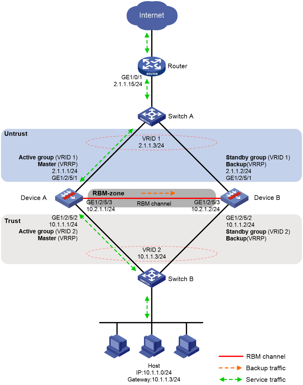
IRF hot backup in active/standby mode with redundancy groups
Figure 15 shows a typical model of using redundancy groups with IRF hot backup in active/standby mode. The hot backup system is directly connected to the upstream and downstream Layer 3 switches by Layer 3 interfaces. To use this scheme, perform the following tasks:
· Configure Device A and Device B to form an IRF fabric.
· On the IRF fabric, create uplink Reth interface Reth 11 and downlink Reth interface Reth 12. Configure the Reth member interfaces on Device A to be active.
· On the IRF fabric, create redundancy group A and assign Reth 11 and Reth 12 to it. Configure Device A as the high-priority node in the redundancy group.
· On Switch A, perform the following tasks:
¡ Configure Port A1 and Port A2 to operate at Layer 2, and assign them to VLAN 11 as access interfaces.
¡ Configure Port A3 to operate at Layer 2, and assign it to VLAN 10 as an access interface.
¡ Create VLAN-interface 10 and VLAN-interface 11, and assign IP addresses to them.
· On Switch B, perform the following tasks:
¡ Configure Port B1 and Port B2 to operate at Layer 2, and assign them to VLAN 12 as access interfaces.
¡ Configure Port B3 to operate at Layer 2, and assign it to VLAN 20 as an access interface.
¡ Create VLAN-interface 12 and VLAN-interface 20, and assign IP addresses to them.
· On the host, specify the IP address of VLAN-interface 20 on Switch B (10.1.1.1) as the default gateway.
· Configure routes on all devices for them to reach one another.
Figure 15 Network model for using redundancy groups with IRF hot backup in active/standby mode
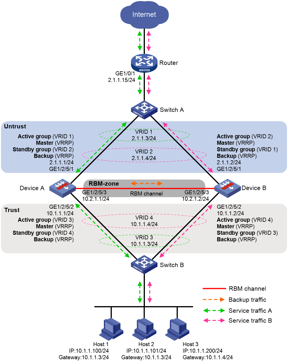
IRF hot backup in dual-active mode with redundancy groups
Figure 15 shows a typical model of using redundancy groups with IRF hot backup in dual-active mode. The hot backup system is directly connected to the upstream and downstream Layer 3 switches by Layer 3 interfaces. To use this scheme, perform the following tasks:
· Configure Device A and Device B to form an IRF fabric.
· On the IRF fabric, create uplink Reth interfaces Reth 11 and Reth 21 and downlink Reth interfaces Reth 12 and Reth 22. Configure the member interfaces of Reth 11 and Reth 12 on Device A to be active, and configure the member interfaces of Reth 21 and Reth 22 on Device B to be active.
· On the IRF fabric, configure redundancy groups as follows:
¡ Configure redundancy group A and assign Reth 11 and Reth 12 to it. Configure Device A as the high-priority node in the redundancy group.
¡ Configure redundancy group B and assign Reth 21 and Reth 22 to it. Configure Device B as the high-priority node in the redundancy group.
· On Switch A, perform the following tasks:
¡ Configure Port A1 and Port A2 to operate at Layer 2, and assign them to VLAN 11 and VLAN 21 as trunk interfaces.
¡ Configure Port A3 to operate at Layer 2, and assign it to VLAN 10.
¡ Create VLAN-interface 10, VLAN-interface 11, and VLAN-interface 12, and assign IP addresses to them.
· On Switch B, perform the following tasks:
¡ Configure Port B1 and Port B2 to operate at Layer 2, and assign them to VLAN 12 and VLAN 22 as trunk interfaces.
¡ Configure Port B3 to operate at Layer 2, and assign it to VLAN 20.
¡ Configure Port B4 to operate at Layer 2, and assign it to VLAN 30.
¡ Create VLAN-interface 12, VLAN-interface 20, VLAN-interface 22, and VLAN-interface 30, and assign IP addresses to them.
· On Host A, specify the IP address of VLAN-interface 20 on Switch B (10.1.1.1) as the default gateway. On Host B, specify the IP address of VLAN-interface 30 on Switch B (10.10.1.1) as the default gateway.
· Configure routes on all devices for them to reach one another.
· On Switch A and Switch B, configure routing settings to ensure symmetric forwarding of flows and even distribution of traffic among Device A and Device B.
Figure 16 Network model for using redundancy groups with IRF hot backup in dual-active mode
IRF hot backup in dual-active mode with link aggregations
Figure 17 shows a typical model of using link aggregations with IRF hot backup in dual-active mode. The hot backup system is directly connected to the upstream and downstream Layer 3 switches by Layer 3 interfaces. To use this scheme, perform the following tasks:
· Configure Device A and Device B to form an IRF fabric.
· On the IRF fabric, configure link aggregations as follows:
¡ Create Route-Aggregation 1 and assign the two uplink Layer 3 physical interfaces to the aggregation group.
¡ Create Route-Aggregation 2 and assign the two downlink Layer 3 physical interfaces to the aggregation group.
¡ Enable local-first load sharing for link aggregation.
· On Switch A, perform the following tasks:
¡ Configure Port A1 and Port A2 as Layer 2 access interfaces.
¡ Configure Port A3 to operate at Layer 2, and assign it to VLAN 10 as an access interface.
¡ Create Bridge-Aggregation 1 and assign the physical interfaces attached to the IRF fabric to the aggregation group. Assign the aggregate interface to VLAN 11.
¡ Create VLAN-interface 10 and VLAN-interface 11, and assign IP addresses to them.
· On Switch B, perform the following tasks:
¡ Configure Port B1 and Port B2 as Layer 2 access interfaces.
¡ Configure Port B3 to operate at Layer 2, and assign it to VLAN 20 as an access interface.
¡ Create Bridge-Aggregation 1 and assign the physical interfaces attached to the IRF fabric to the aggregation group. Assign the aggregate interface to VLAN 12.
¡ Create VLAN-interface 12 and VLAN-interface 20, and assign IP addresses to them.
· On the host, specify the IP address of VLAN-interface 20 on Switch B (10.1.1.1) as the default gateway.
· Configure routes on all devices for them to reach one another.
Figure 17 Network model for using link aggregations with IRF hot backup in dual-active mode
Comparison between the deployment schemes
Table 1 Comparison between the deployment schemes of IRF hot backup
|
Scheme |
Features |
Weakness |
|
IRF hot backup in active/standby mode with redundancy groups |
· Simple configuration. · Applicable to any networks. |
Cannot make full use of resources because only one device forwards traffic. |
|
IRF hot backup in dual-active mode with redundancy groups |
· Symmetric traffic forwarding and low traffic load on the IRF link. · Applicable to medium-sized and large networks. |
· Complicated configuration. · More configuration when devices are added. |
|
IRF hot backup in dual-active mode with link aggregations |
· Simple configuration. · High scalability. · Applicable to small and medium-sized networks. |
· Cannot ensure symmetric forwarding of flows. · Heavy traffic on the IRF link when a large amount of asymmetric-path traffic exists. |
Prerequisites for IRF hot backup configuration
Before you configure IRF hot backup, verify that the following hardware and software settings are the same on the member devices of the hot backup system:
· Device model.
· Software version.
· Location, number, and type of service modules.
· Location, number, and type of interface modules.
IRF hot backup configuration flow
Figure 18 shows the configuration flow for IRF hot backup.
Figure 18 IRF hot backup configuration flow chart
IRF hot backup configuration examples
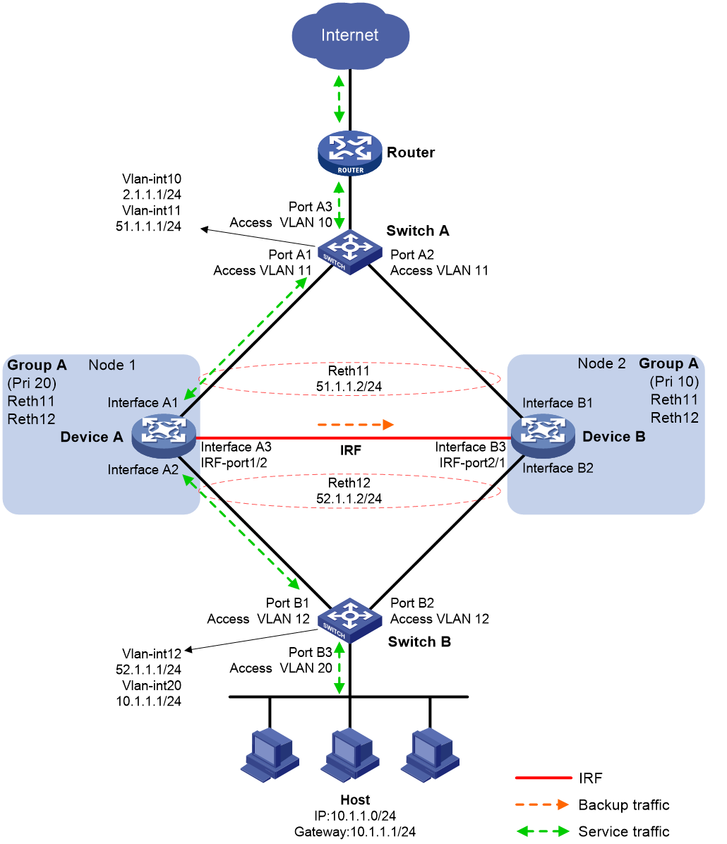
Example: Configuring an IRF hot backup system in active/standby mode with one redundancy group
Network configuration
As shown in Figure 19, set up an IRF hot backup system at the border between the Internet and the internal network of an enterprise to ensure service continuity.
· Configure the hot backup system to operate in active/standby mode.
· Configure Device A and Device B as the primary device and the secondary device, respectively.
Procedure
1. Configure IRF:
¡ Configure Device A:
# Bind GigabitEthernet 1/2/5/3 to IRF-port 1/2 and save the configuration.
<DeviceA> system-view
[DeviceA] interface gigabitethernet 1/2/5/3
[DeviceA-GigabitEthernet1/2/5/3] shutdown
[DeviceA-GigabitEthernet1/2/5/3] quit
[DeviceA] irf-port 1/2
[DeviceA-irf-port1/2] port group interface gigabitethernet 1/2/5/3
You must perform the following tasks for a successful IRF setup:
Save the configuration after completing IRF configuration.
Execute the "irf-port-configuration active" command to activate the IRF ports.
[DeviceA-irf-port1/2] quit
[DeviceA] interface gigabitethernet 1/2/5/3
[DeviceA-GigabitEthernet1/2/5/3] undo shutdown
[DeviceA-GigabitEthernet1/2/5/3] quit
[DeviceA] save
[DeviceA] irf-port-configuration active
# Change the member priority of Device A to 2 for it to be elected as the master.
[DeviceA] irf member 1 priority 2
# Activate the IRF port configuration.
[DeviceA] irf-port-configuration active
¡ Configure Device B:
# Change the member ID of Device B to 2, and reboot the device to have the change take effect.
<DeviceB> system-view
[DeviceB] irf member 1 renumber 2
Renumbering the member ID may result in configuration change or loss. Continue? [Y/N]:y
[DeviceB] quit
<DeviceB> reboot
# Connect Device B to Device A, as shown in Figure 19.
# Log in to Device B. (Details not shown.)
# Bind GigabitEthernet 2/2/5/3 to IRF port 2/1, and save the configuration.
<DeviceB> system-view
[DeviceB] interface gigabitethernet 2/2/5/3
[DeviceB-GigabitEthernet2/2/5/3] shutdown
[DeviceB-GigabitEthernet2/2/5/3] quit
[DeviceB] irf-port 2/1
[DeviceB-irf-port2/1] port group interface gigabitethernet 2/2/5/3
You must perform the following tasks for a successful IRF setup:
Save the configuration after completing IRF configuration.
Execute the "irf-port-configuration active" command to activate the IRF ports.
[DeviceB-irf-port2/1] quit
[DeviceB] interface gigabitethernet 2/2/5/3
[DeviceB-GigabitEthernet2/2/5/3] undo shutdown
[DeviceB-GigabitEthernet2/2/5/3] quit
[DeviceB] save
# Activate the IRF port configuration.
[DeviceB] irf-port-configuration active
The two devices perform master election, and the one that has lost the election reboots to form an IRF fabric with the master. In this example, Device B reboots.
2. Configure Track to monitor the status of the uplink and downlink interfaces of the IRF fabric.
<DeviceA> system-view
[DeviceA] track 1 interface gigabitethernet 1/2/5/1
[DeviceA-track-1] quit
[DeviceA] track 2 interface gigabitethernet 1/2/5/2
[DeviceA-track-2] quit
[DeviceA] track 3 interface gigabitethernet 2/2/5/1
[DeviceA-track-3] quit
[DeviceA] track 4 interface gigabitethernet 2/2/5/2
[DeviceA-track-4] quit
3. Configure Reth interfaces:
# Configure Reth 11.
[DeviceA] interface reth 11
[DeviceA-Reth11] member interface gigabitethernet 1/2/5/1 priority 100
[DeviceA-Reth11] member interface gigabitethernet 2/2/5/1 priority 80
[DeviceA-Reth11] ip address 51.1.1.2 255.255.255.0
[DeviceA-Reth11] quit
# Configure Reth 12.
[DeviceA] interface reth 12
[DeviceA-Reth12] member interface gigabitethernet 1/2/5/2 priority 100
[DeviceA-Reth12] member interface gigabitethernet 2/2/5/2 priority 80
[DeviceA-Reth12] ip address 52.1.1.2 255.255.255.0
[DeviceA-Reth12] quit
4. Configure a failover group.
[DeviceA] failover group group1
[DeviceA-failover-group-group1] bind chassis 1 slot 2 primary
[DeviceA-failover-group-group1] bind chassis 2 slot 2 secondary
[DeviceA-failover-group-group1] quit
5. Configure a redundancy group:
# Create redundancy group a.
[DeviceA] redundancy group a
# Assign Reth 11 and Reth 12 to redundancy group a.
[DeviceA-redundancy-group-a] member interface reth 11
[DeviceA-redundancy-group-a] member interface reth 12
# Assign failover group group1 to redundancy group a.
[DeviceA-redundancy-group-a] member failover group group1
# Bind Node 1 to Device A, set the priority of the node to 20, and associate track entries 1 and 2 with the node.
[DeviceA-redundancy-group-a] node 1
[DeviceA-redundancy-group-a-node1] bind slot 1
[DeviceA-redundancy-group-a-node1] priority 20
[DeviceA-redundancy-group-a-node1] track 1 interface gigabitethernet 1/2/5/1
[DeviceA-redundancy-group-a-node1] track 2 interface gigabitethernet 1/2/5/2
[DeviceA-redundancy-group-a-node1] quit
# Bind Node 2 to Device B, set the priority of the node to 10, and associate track entries 3 and 4 with the node.
[DeviceA-redundancy-group-a] node 2
[DeviceA-redundancy-group-a-node2] bind slot 2
[DeviceA-redundancy-group-a-node2] priority 10
[DeviceA-redundancy-group-a-node2] track 3 interface gigabitethernet 2/2/5/1
[DeviceA-redundancy-group-a-node2] track 4 interface gigabitethernet 2/2/5/2
[DeviceA-redundancy-group-a-node2] quit
[DeviceA-redundancy-group-a] quit
6. Enable session synchronization.
[DeviceA] session synchronization enable
7. Enable session active/standby mode.
[DeviceA] undo session dual-active enable
8. Assign IP addresses to interfaces and configure routes, security zones, zone pairs, and interzone policies. Make sure the network connections are available. (Details not shown.)
9. Assign Reth 11 to security zone Untrust, and assign Reth 12 to security zone Trust. (Details not shown.)
10. Configure Switch A:
|
|
NOTE: This step only provides the brief configuration procedure. |
¡ Create VLAN 10 and VLAN 11.
¡ Configure GigabitEthernet 1/0/1 and GigabitEthernet 1/0/2 to operate at Layer 2, and assign them to VLAN 11 as access interfaces.
¡ Configure GigabitEthernet 1/0/3 to operate at Layer 2, and assign it to VLAN 10 as an access interface.
¡ Assign 51.1.1.1/24 and 2.1.1.1/24 to VLAN-interface 11 and VLAN-interface 10, respectively.
¡ Specify 51.1.1.2 (IP address of Reth 11) as the next hop of the route to the internal network, and specify 2.1.1.2 (an IP address on the router) as the next hop of the route to the Internet.
11. Configure Switch B:
|
|
NOTE: This step only provides the brief configuration procedure. |
¡ Create VLAN 12 and VLAN 20.
¡ Configure GigabitEthernet 1/0/1 and GigabitEthernet 1/0/2 to operate at Layer 2, and assign them to VLAN 12 as access interfaces.
¡ Configure GigabitEthernet 1/0/3 to operate at Layer 2, and assign it to VLAN 20 as an access interface.
¡ Assign 52.1.1.1/24 and 10.1.1.1/24 to VLAN-interface 12 and VLAN-interface 20.
¡ Specify 52.1.1.2 (IP address of Reth 12) as the next hop of the route to the Internet.
12. On the host, specify 10.1.1.1 (IP address of VLAN-interface 20 on Switch B) as the default gateway.
Verifying the configuration
# Verify that Device A is the high-priority node in the redundancy group and the member interfaces on both nodes are up when Device A and Device B are operating correctly.
[DeviceA] display redundancy group a
Redundancy group a (ID 1):
Node ID Slot Priority Status Track weight
1 Slot1 20 Primary 255
2 Slot2 10 Secondary 255
Preempt delay time remained : 0 min
Preempt delay timer setting : 60 min
Remaining hold-down time : 0 sec
Hold-down timer setting : 1 sec
Manual switchover request : No
Member interfaces:
Reth11 Reth12
Member failover groups:
Group1
Node 1:
Track info:
Track Status Reduced weight Interface
1 Positive 255 GE1/2/5/1
2 Positive 255 GE1/2/5/2
Node 2:
Track info:
Track Status Reduced weight Interface
3 Positive 255 GE2/2/5/1
4 Positive 255 GE2/2/5/2
# Shut down GigabitEthernet 1/2/5/2 on Device A and verify that Device B takes over to forward traffic.
[DeviceA] interface gigabitethernet 1/2/5/2
[DeviceA-GigabitEthernet1/2/5/2] shutdown
[DeviceA-GigabitEthernet1/2/5/2] display redundancy group a
Redundancy group a (ID 1):
Node ID Slot Priority Status Track weight
1 Slot1 20 Secondary -255
2 Slot2 10 Primary 255
Preempt delay time remained : 0 min
Preempt delay timer setting : 1 min
Remaining hold-down time : 0 sec
Hold-down timer setting : 1 sec
Manual switchover request : No
Member interfaces:
Reth11 Reth12
Member failover groups:
Group1
Node 1:
Track info:
Track Status Reduced weight Interface
1 Negative 255 GE1/2/5/1
2 Negative(Faulty) 255 GE1/2/5/2
Node 2:
Track info:
Track Status Reduced weight Interface
3 Positive 255 GE2/2/5/1
4 Positive 255 GE2/2/5/2
Example: Configuring an IRF hot backup system in dual-active mode with two redundancy groups
Network configuration
As shown in Figure 20, set up an IRF hot backup system at the border between the Internet and the internal network of an enterprise to ensure service continuity.
· Configure the hot backup system to operate in dual-active mode.
· Configure Device A and Device B to process the traffic of Host A and Host B, respectively.

Procedure
1. Configure IRF as described in "Example: Configuring an IRF hot backup system in active/standby mode with one redundancy group."
2. Configure Layer 3 Ethernet subinterfaces to terminate the outermost VLAN ID of packets.
<DeviceA> system-view
[DeviceA] interface gigabitethernet 1/2/5/1.11
[DeviceA-GigabitEthernet1/2/5/1.11] vlan-type dot1q vid 11
[DeviceA] interface gigabitethernet 1/2/5/1.21
[DeviceA-GigabitEthernet1/2/5/1.21] vlan-type dot1q vid 21
[DeviceA] interface gigabitethernet 1/2/5/2.12
[DeviceA-GigabitEthernet1/2/5/2.12] vlan-type dot1q vid 12
[DeviceA] interface gigabitethernet 1/2/5/2.22
[DeviceA-GigabitEthernet1/2/5/2.22] vlan-type dot1q vid 22
[DeviceA] interface gigabitethernet 2/2/5/1.11
[DeviceA-GigabitEthernet2/2/5/1.11] vlan-type dot1q vid 11
[DeviceA] interface gigabitethernet 2/2/5/1.21
[DeviceA-GigabitEthernet2/2/5/1.21] vlan-type dot1q vid 21
[DeviceA] interface gigabitethernet 2/2/5/2.12
[DeviceA-GigabitEthernet2/2/5/2.12] vlan-type dot1q vid 12
[DeviceA] interface gigabitethernet 2/2/5/2.22
[DeviceA-GigabitEthernet2/2/5/2.22] vlan-type dot1q vid 22
[DeviceA-GigabitEthernet2/2/5/2.22] quit
3. Configure Track to monitor the status of the uplink and downlink subinterfaces of the IRF fabric.
[DeviceA] track 1 interface gigabitethernet 1/2/5/1.11
[DeviceA-track-1] quit
[DeviceA] track 2 interface gigabitethernet 1/2/5/1.21
[DeviceA-track-2] quit
[DeviceA] track 3 interface gigabitethernet 1/2/5/2.12
[DeviceA-track-3] quit
[DeviceA] track 4 interface gigabitethernet 1/2/5/2.22
[DeviceA-track-4] quit
[DeviceA] track 5 interface gigabitethernet 2/2/5/1.11
[DeviceA-track-5] quit
[DeviceA] track 6 interface gigabitethernet 2/2/5/1.21
[DeviceA-track-6] quit
[DeviceA] track 7 interface gigabitethernet 2/2/5/2.12
[DeviceA-track-7] quit
[DeviceA] track 8 interface gigabitethernet 2/2/5/2.22
[DeviceA-track-8] quit
4. Configure Reth interfaces:
# Configure Reth 11.
[DeviceA] interface reth 11
[DeviceA-Reth11] member interface gigabitethernet 1/2/5/1.11 priority 100
[DeviceA-Reth11] member interface gigabitethernet 2/2/5/1.11 priority 80
[DeviceA-Reth11] ip address 51.1.1.2 255.255.255.0
[DeviceA-Reth11] quit
# Configure Reth 12.
[DeviceA] interface reth 12
[DeviceA-Reth12] member interface gigabitethernet 1/2/5/2.12 priority 100
[DeviceA-Reth12] member interface gigabitethernet 2/2/5/2.12 priority 80
[DeviceA-Reth12] ip address 52.1.1.2 255.255.255.0
[DeviceA-Reth12] quit
# Configure Reth 21.
[DeviceA] interface reth 21
[DeviceA-Reth21] member interface gigabitethernet 1/2/5/1.21 priority 80
[DeviceA-Reth21] member interface gigabitethernet 2/2/5/1.21 priority 100
[DeviceA-Reth21] ip address 61.1.1.2 255.255.255.0
[DeviceA-Reth21] quit
# Configure Reth 22.
[DeviceA] interface reth 22
[DeviceA-Reth22] member interface gigabitethernet 1/2/5/2.22 priority 80
[DeviceA-Reth22] member interface gigabitethernet 2/2/5/2.22 priority 100
[DeviceA-Reth22] ip address 62.1.1.2 255.255.255.0
[DeviceA-Reth22] quit
5. Configure failover groups:
# Configure failover group group1.
[DeviceA] failover group group1
[DeviceA-failover-group-group1] bind chassis 1 slot 2 primary
[DeviceA-failover-group-group1] bind chassis 2 slot 2 secondary
[DeviceA-failover-group-group1] quit
# Configure failover group group2.
[DeviceA] failover group group2
[DeviceA-failover-group-group2] bind chassis 1 slot 2 secondary
[DeviceA-failover-group-group2] bind chassis 2 slot 2 primary
[DeviceA-failover-group-group2] quit
6. Configure redundancy groups:
# Create redundancy group a.
[DeviceA] redundancy group a
# Assign Reth 11 and Reth 12 to redundancy group a.
[DeviceA-redundancy-group-a] member interface reth 11
[DeviceA-redundancy-group-a] member interface reth 12
# Assign failover group group1 to redundancy group a.
[DeviceA-redundancy-group-a] member failover group group1
# Bind Node 1 to Device A, set the priority of the node to 20, and associate track entries 1 and 3 with the node.
[DeviceA-redundancy-group-a] node 1
[DeviceA-redundancy-group-a-node1] bind slot 1
[DeviceA-redundancy-group-a-node1] priority 20
[DeviceA-redundancy-group-a-node1] track 1 interface gigabitethernet 1/2/5/1.11
[DeviceA-redundancy-group-a-node1] track 3 interface gigabitethernet 1/2/5/2.12
[DeviceA-redundancy-group-a-node1] quit
# Bind Node 2 to Device B, set the priority of the node to 10, and associate track entries 5 and 7 with the node.
[DeviceA-redundancy-group-a] node 2
[DeviceA-redundancy-group-a-node2] bind slot 2
[DeviceA-redundancy-group-a-node2] priority 10
[DeviceA-redundancy-group-a-node2] track 5 interface gigabitethernet 2/2/5/1.11
[DeviceA-redundancy-group-a-node2] track 7 interface gigabitethernet 2/2/5/2.12
[DeviceA-redundancy-group-a-node2] quit
[DeviceA-redundancy-group-a] quit
# Create redundancy group b.
[DeviceA] redundancy group b
# Assign Reth 21 and Reth 22 to redundancy group b.
[DeviceA-redundancy-group-b] member interface reth 21
[DeviceA-redundancy-group-b] member interface reth 22
# Assign failover group group2 to redundancy group b.
[DeviceA-redundancy-group-b] member failover group group2
# Bind Node 1 to Device A, set the priority of the node to 10, and associate track entries 2 and 4 with the node.
[DeviceA-redundancy-group-b] node 1
[DeviceA-redundancy-group-b-node1] bind slot 1
[DeviceA-redundancy-group-b-node1] priority 10
[DeviceA-redundancy-group-b-node1] track 2 interface gigabitethernet 1/2/5/1.21
[DeviceA-redundancy-group-b-node1] track 4 interface gigabitethernet 1/2/5/2.22
[DeviceA-redundancy-group-b-node1] quit
# Bind Node 2 to Device B, set the priority of the node to 20, and associate track entries 6 and 8 with the node.
[DeviceA-redundancy-group-b] node 2
[DeviceA-redundancy-group-b-node2] bind slot 2
[DeviceA-redundancy-group-b-node2] priority 20
[DeviceA-redundancy-group-b-node2] track 6 interface gigabitethernet 2/2/5/1.21
[DeviceA-redundancy-group-b-node2] track 8 interface gigabitethernet 2/2/5/2.22
[DeviceA-redundancy-group-b-node2] quit
[DeviceA-redundancy-group-b] quit
7. Enable session synchronization.
[DeviceA] session synchronization enable
8. Enable session dual-active mode.
[DeviceA] session dual-active enable
9. Assign IP addresses to interfaces and configure routes, security zones, zone pairs, and interzone policies. Make sure the network connections are available. (Details not shown.)
10. Assign Reth 11 and Reth 21 to security zone Untrust, and assign Reth 12 and Reth 22 to security zone Trust. (Details not shown.)
11. Configure the static routes to the external network. Specify the next hop of the route to 10.1.1.0/24 as 52.1.1.1(IP address of VLAN-interface 12 on Switch B). Specify the next hop of the route to 10.10.1.0/24 as 62.1.1.1 (IP address of VLAN-interface 22 on Switch B).
[DeviceA] ip route-static 10.1.1.0 24 52.1.1.1
[DeviceA] ip route-static 10.10.1.0 24 62.1.1.1
12. Configure PBR policies for the traffic sent from the internal network to reach the Internet.
# Configure ACL 2000 to permit the packets from 10.1.1.0/24.
[DeviceA] acl basic 2000
[DeviceA-acl-ipv4-basic-2000] rule 10 permit source 10.1.1.0 0.0.0.255
[DeviceA-acl-ipv4-basic-2000] quit
# Configure ACL 2001 to permit the packets from 10.10.1.0/24.
[DeviceA] acl basic 2001
[DeviceA-acl-ipv4-basic-2001] rule 10 permit source 10.10.1.0 0.0.0.255
[DeviceA-acl-ipv4-basic-2001] quit
# Configure PBR policy aaa to specify 51.1.1.1 (IP address of VLAN-interface 11 on Switch A) as the next hop of the packets from 10.1.1.0/24.
[DeviceA] policy-based-route aaa permit node 0
[DeviceA-pbr-aaa-0] if-match acl 2000
[DeviceA-pbr-aaa-0] apply next-hop 51.1.1.1
[DeviceA-pbr-aaa-0] quit
# Configure PBR policy bbb to specify 61.1.1.1 (IP address of VLAN-interface 21 on Switch B) as the next hop of the packets from 10.10.1.0/24.
[DeviceA] policy-based-route bbb permit node 0
[DeviceA-pbr-bbb-0] if-match acl 2001
[DeviceA-pbr-bbb-0] apply next-hop 61.1.1.1
[DeviceA-pbr-bbb-0] quit
# Apply PBR policy aaa to Reth 12 for Device A to forward the traffic sent from 10.1.1.0/24 to the Internet.
[DeviceA] interface reth 12
[DeviceA-Reth12] ip policy-based-route aaa
[DeviceA-Reth12] quit
# Apply PBR policy bbb to Reth 22 for Device B to forward the traffic sent from 10.10.1.0/24 to the Internet.
[DeviceA] interface reth 22
[DeviceA-Reth22] ip policy-based-route bbb
[DeviceA-Reth22] quit
13. Configure Switch A:
|
|
NOTE: This step only provides the brief configuration procedure. |
a. Create VLAN 10, VLAN 11, and VLAN 21.
b. Configure GigabitEthernet 1/0/1 and GigabitEthernet 1/0/2 to operate at Layer 2, and assign them to VLAN 11 and VLAN 21 as trunk interfaces.
c. Configure GigabitEthernet 1/0/3 to operate at Layer 2, and assign it to VLAN 10 as an access interface.
d. Assign 51.1.1.1/24, 61.1.1.1/24, and 2.1.1.1/24 to VLAN-interface 11, VLAN-interface 21, and VLAN-interface 10, respectively.
e. Configure routes as follows:
- Specify 51.1.1.2 (IP address of Reth 11) as the next hop of the route to 10.1.1.0/24.
- Specify 61.1.1.2 (IP address of Reth 21) as the next hop of the route to 10.10.1.0/24.
- Specify 2.1.1.2 (IP address of the peer interface of VLAN-interface 10) as the next hop of the route to the Internet.
14. Configure Switch B:
|
|
NOTE: This step only provides the brief configuration procedure. |
a. Create VLAN 12, VLAN 20, VLAN 22, and VLAN 30.
b. Configure GigabitEthernet 1/0/1 and GigabitEthernet 1/0/2 to operate at Layer 2, and assign them to VLAN 12 and VLAN 22 as trunk interfaces.
c. Configure GigabitEthernet 1/0/3 to operate at Layer 2, and assign it to VLAN 20 as an access interface.
d. Configure GigabitEthernet 1/0/4 to operate at Layer 2, and assign it to VLAN 30 as an access interface.
e. Assign 52.1.1.1/24, 62.1.1.1/24, 10.1.1.1/24, and 10.10.1.1/24 to VLAN-interface 12, VLAN-interface 22, VLAN-interface 20, and VLAN-interface 30, respectively.
f. Configure PBR policies as follows:
- Specify 52.1.1.2 (IP address of Reth 12) as the next hop of the packets from 10.1.1.0/24.
- Specify 62.1.1.2 (IP address of Reth 22) as the next hop of the packets from 10.10.1.0/24.
15. On Host A, specify 10.1.1.1 (IP address of VLAN-interface 20 on Switch B) as the default gateway. On Host B, specify 10.10.1.1 (IP address of VLAN-interface 30 on Switch B) as the default gateway.
Verifying the configuration
1. Verify the configuration when both Device A and Device B are operating correctly.
# Verify that Device A is the high-priority node in redundancy group a and the member interfaces on both nodes are up.
[DeviceA] display redundancy group a
Redundancy group a (ID 2):
Node ID Slot Priority Status Track weight
1 Slot1 20 Primary 255
2 Slot2 10 Secondary 255
Preempt delay time remained : 0 sec
Preempt delay timer setting : 60 sec
Remaining hold-down time : 0 sec
Hold-down timer setting : 1 sec
Manual switchover request : No
Member interfaces:
Reth11 Reth12
Member failover groups:
Group1
Node 1:
Track info:
Track Status Reduced weight Interface
1 Positive 255 GE1/2/5/1.11
3 Positive 255 GE1/2/5/2.12
Node 2:
Track info:
Track Status Reduced weight Interface
5 Positive 255 GE2/2/5/1.11
7 Positive 255 GE2/2/5/2.12
# Verify that Device B is the high-priority node in redundancy group b and the member interfaces on both nodes are up.
[DeviceA] display redundancy group b
Redundancy group b (ID 3):
Node ID Slot Priority Status Track weight
1 Slot1 10 Secondary 255
2 Slot2 20 Primary 255
Preempt delay time remained : 0 sec
Preempt delay timer setting : 60 sec
Remaining hold-down time : 0 sec
Hold-down timer setting : 1 sec
Manual switchover request : No
Member interfaces:
Reth21 Reth22
Member failover groups:
Group2
Node 1:
Track info:
Track Status Reduced weight Interface
2 Positive 255 GE1/2/5/1.21
4 Positive 255 GE1/2/5/2.22
Node 2:
Track info:
Track Status Reduced weight Interface
6 Positive 255 GE2/2/5/1.21
8 Positive 255 GE2/2/5/2.22
2. Verify the configuration when Device A is down.
# Shut down GigabitEthernet 1/2/5/2 on Device A.
[DeviceA] interface gigabitethernet 1/2/5/2
[DeviceA-GigabitEthernet1/2/5/2] shutdown
# Verify that Device B takes over to forward traffic in redundancy group a.
[DeviceA-GigabitEthernet1/2/5/2] display redundancy group a
Redundancy group a (ID 2):
Node ID Slot Priority Status Track weight
1 Slot1 20 Secondary -255
2 Slot2 10 Primary 255
Preempt delay time remained : 0 sec
Preempt delay timer setting : 60 sec
Remaining hold-down time : 0 sec
Hold-down timer setting : 1 sec
Manual switchover request : No
Member interfaces:
Reth11 Reth12
Member failover groups:
Group1
Node 1:
Track info:
Track Status Reduced weight Interface
1 Negative 255 GE1/2/5/1.11
3 Negative(Faulty) 255 GE1/2/5/2.12
Node 2:
Track info:
Track Status Reduced weight Interface
5 Positive 255 GE2/2/5/1.11
7 Positive 255 GE2/2/5/2.12
# Verify that Device B is the high-priority node in redundancy group b and the member interfaces on Node 2 are up.
[DeviceA-GigabitEthernet1/2/5/2] display redundancy group b
Redundancy group b (ID 3):
Node ID Slot Priority Status Track weight
1 Slot1 10 Secondary 0
2 Slot2 20 Primary 255
Preempt delay time remained : 0 sec
Preempt delay timer setting : 60 sec
Remaining hold-down time : 0 sec
Hold-down timer setting : 1 sec
Manual switchover request : No
Member interfaces:
Reth21 Reth22
Member failover groups:
Group2
Node 1:
Track info:
Track Status Reduced weight Interface
2 Positive 255 GE1/2/5/1.21
4 Negative 255 GE1/2/5/2.22
Node 2:
Track info:
Track Status Reduced weight Interface
6 Positive 255 GE2/2/5/1.21
8 Positive 255 GE2/2/5/2.22