- Table of Contents
-
- 17-Network Management and Monitoring Configuration Guide
- 00-Preface
- 01-System maintenance and debugging configuration
- 02-NQA configuration
- 03-NTP configuration
- 04-PoE configuration
- 05-SNMP configuration
- 06-RMON configuration
- 07-Event MIB configuration
- 08-NETCONF configuration
- 09-SmartMC configuration
- 10-CWMP configuration
- 11-EAA configuration
- 12-Process monitoring and maintenance configuration
- 13-Sampler configuration
- 14-Mirroring configuration
- 15-NetStream configuration
- 16-IPv6 NetStream configuration
- 17-sFlow configuration
- 18-Flow log configuration
- 19-Information center configuration
- 20-Packet capture configuration
- 21-Cloud connection configuration
- Related Documents
-
| Title | Size | Download |
|---|---|---|
| 09-SmartMC configuration | 214.21 KB |
Restrictions: Hardware compatibility with SmartMC
Restrictions and guidelines: SmartMC configuration
Setting the FTP server information
Configuring an outgoing interface for the SmartMC network
Enabling automatic Ethernet link aggregation
Modifying the password for the default user for members
Deploying a batch file to members
Configuring a batch file for ports connecting APs or IP phones
Backing up configuration files
Configuring resource monitoring
Upgrading the startup software and configuration file on members
About upgrading the startup software and configuration file on members
Restrictions and guidelines for startup software and configuration file upgrade
Upgrading the startup software and configuration file on members
Upgrading the startup software and configuration file on all members in SmartMC groups
Refreshing the network topology
Display and maintenance commands for SmartMC
SmartMC configuration examples
Configuring SmartMC
About SmartMC
Smart Management Center (SmartMC) centrally manages and maintains dispersed network devices at network edges. In a SmartMC network, only one device acts as the commander and the remaining devices all act as members. SmartMC provides the following features for you to manage the members from the commander:
· Configuration file backup and download.
· Software upgrade.
· Configuration deployment.
· Faulty member replacement.
SmartMC network framework
Figure 1 shows the basic framework of a SmartMC network.
Figure 1 SmartMC network framework
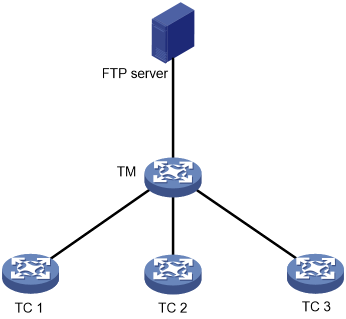
The SmartMC network contains the following elements:
· Commander—Also called topology master (TM), which manages all members in the SmartMC network.
· Member—Also called topology client (TC), which is managed by the commander.
· FTP server—Stores startup software images and configuration files for the commander and members.
SmartMC network establishment
A SmartMC network can be established automatically or manually. In an automatically established SmartMC network, the commander obtains member information through NETCONF sessions to form the network topology. The member information includes port information, LLDP neighbor information, STP information, device type, and software version. In a manually established SmartMC network, the commander obtains member's LLDP neighbor information through NETCONF sessions and member's hardware information through SNMP Get operations.
Automatic SmartMC network establishment
The commander and members use the following procedure to establish a SmartMC network:
1. After SmartMC is enabled, the commander broadcasts a SmartMC packet at 15-second intervals to detect members in the network. The SmartMC packet contains information of the commander, such as its bridge MAC address and the IP address of VLAN-interface 1.
2. When a member receives the packet, it records the commander information, and returns a response packet to the commander. The response packet contains information of the member, such as its bridge MAC address and the IP address of VLAN-interface 1.
3. When the commander receives the response packet, it initiates a NETCONF session to the member with the default username admin and the default password admin. The commander then obtains detailed information about the member through the session, including port information, LLDP neighbor information, STP information, device type, and software version.
4. The commander establishes a connection to the member for tracking the liveliness of the member, and adds the member to the SmartMC network.
5. Based on the LLDP neighbor information obtained from all members, the commander forms a SmartMC topology.
After the SmartMC network is established, the commander and members check for the existence of each other by exchanging SmartMC packets.
· When a member receives a SmartMC broadcast packet from the commander, it compares the bridge MAC address in the packet with the recorded bridge MAC address. If the two bridge MAC addresses are the same, the member returns a response packet to the commander. If the member does not receive a broadcast packet from the commander within the limit time, the member determines that the commander does not exist in the network anymore. Then, the member clears the commander information. The limit time is a random value in the range of 60 to 120 seconds.
· When the commander receives a response packet from a member, it compares the bridge MAC address in the packet with the recorded bridge MAC address. If the two bridge MAC addresses are the same, the commander determines that the member still exists in the network. If the commander does not receive a response packet from a member within 150 seconds, the commander determines that the member is offline. Then, the commander sets the status of the member to offline.
Manual SmartMC network establishment
You can log in to the Web interface of the commander, and enter the IP address, username, and password of the members to manually add them to the network. The members can join the network without exchanging SmartMC packets with the commander. For more information, see Comware 7 Web-Based Products User Guide.
After you specify the information of a member on the commander, the commander performs the following operations to add the member to the network:
· Verify that the member can be accessed through Telnet.
· Obtain basic member information, including LLDP neighbor information through NETCONF.
· Obtain hardware information through SNMP Get operations.
SmartMC features
Bulk configuration deployment for members
This feature allows you to deploy multiple command lines to members from the commander, eliminating the need to log in to members and configure the command one by one.
The procedure for bulk configuration deployment is as follows:
1. The commander acts as a Telnet client and establishes Telnet connections to the members.
2. The commander deploys a batch file to the members through Telnet connections. The batch file is created on the commander and contains command lines to be deployed.
3. The members run the command lines in the file.
Bulk configuration deployment for ports connecting APs and IP phones
You can specify a batch file to deploy to ports connecting APs or IP phones. When the commander detects that an AP or IP phone comes online on a port, it obtains the access device type through LLDP and deploys the command lines in the specified file to the port.
If the AP or IP phone disconnects from the port, the configurations on the port remain. When a new device comes online from the port, configurations used by the port depend on the new device type.
· If the new device is still an AP or IP phone, the commander restores the default settings and then deploys configurations to the port based on the device type.
· If the new device is neither an AP nor an IP phone, the commander restores the default settings on the port
Configuration file backup
You can use the following methods to back up the next-startup configuration file on the commander and members:
· Automatic backup—Enable this feature for the commander and all members in the network to immediately perform a backup. After that, the commander and members back up the configuration file at a user-specified interval.
· Manual backup—Manually trigger a backup on the commander or the specified members or SmartMC groups.
To back up the configuration file on a member, the commander instructs the member by unicasting a SmartMC packet. When a member receives the packet, it saves the running configuration to the next-startup configuration file and uploads the file to the FTP server.
Startup software and configuration file upgrade
This feature enables users to upgrade startup software and the configuration file of member devices from the commander.
Before upgrade, you must upload the upgrade files from the commander to the FTP server and specify the upgrade files on the FTP server for the members to download.
The procedure for startup software and configuration file upgrade is as follows:
1. The commander instructs the members (or SmartMC group) to download the upgrade files from the FTP server.
2. The members download the upgrade files from the FTP server.
3. The members upgrade the startup software and configuration file as follows:
¡ Startup software upgrade—Uses a boot loader image to perform an upgrade with the upgrade startup software files. The members might be restarted during the upgrade process.
¡ Configuration file upgrade—Replaces the current configuration file with the upgrade configuration file. The members will not be restarted during the upgrade process.
Faulty member replacement
You can use the following methods to replace a faulty member:
· Automatic replacement—Enables the commander to record the positions of all members in the topology for replacement. When the commander discovers that a new member has physically replaced the faulty member, it compares the new member with the faulty one. The commander performs a replacement if the following requirements are met:
¡ The new member is deployed at the same topological position as the faulty one.
¡ The models of the new member and faulty member are the same.
The commander then instructs the new member to download the configuration file of the faulty member from the FTP server. After downloading the configuration file, the new member runs the configuration file to complete the replacement.
· Manual replacement—After the faulty member is physically replaced, you manually trigger a configuration replacement. The new member will download the configuration file of the faulty member from the FTP server and run the file to complete the replacement.
Outgoing interface for a SmartMC network
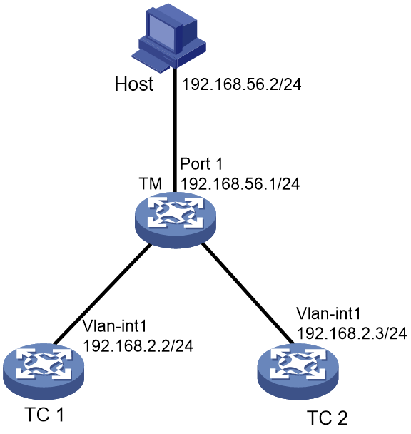
The outgoing interface feature allows hosts connecting to an outgoing interface to access all the members in a SmartMC network. You can configure multiple outgoing interfaces for a SmartMC network.
As shown in Figure 2, the host is connected to port 1 on the TM and TC 1 and TC 2 are in a different network segment than the host. The host can access the Web interface of the TM but cannot access the Web interface of any member.
If port 1 on the TM is configured as the outgoing interface, the system mirrors the IP address of each member to a new address. The new address contains the IP address of the outgoing interface and the port number assigned by the commander to the member in the format of IP address:Port number. This enables the host to access the Web interfaces of members from the Web interface of the TM.
To access the Web interface of a member, enter the Web interface of the commander, and click Visibility from the navigation pane. Then, click the Topology tab, select the target member, and click Login to Web interface.
Automatic link aggregation
Automatic link aggregation automatically bundles multiple physical Ethernet links between two members into one logical link, called an aggregate link. This feature provides increased link bandwidth and improved link reliability.
|
|
NOTE: · Automatic link aggregation cannot be performed between the commander and a member, or between a member and a device outside the SmartMC network. You can aggregate the links between the commander and a member manually. For more information about manual link aggregation, see Ethernet link aggregation in Layer 2—LAN Switching Configuration Guide. · Enabling or disabling automatic link aggregation might cause network flapping, and the members might go offline for a short period of time. |
VLAN creation for members
To simplify configuration and management, you can create a VLAN for members. Then, all access ports on a member that are not connected to other members or the commander are assigned to the VLAN.
If a member has access ports that are connected to offline devices, you must remove the offline devices before creating a VLAN for the member.
The VLAN creation fails for a member if one or more access ports cannot be assigned to the VLAN. If the VLAN creation fails, the VLAN memberships for the access ports are restored to the state before the VLAN was created.
The failure to create a VLAN for a member does not affect the VLAN creation for other members.
Resource monitoring
Resource monitoring allows you to view resource usage of commanders and members on the commander, such as CPU usage, memory usage, and temperature information.
Restrictions: Hardware compatibility with SmartMC
|
Model |
SmartMC compatibility |
|
MSR810, MSR810-W, MSR810-W-DB, MSR810-LM, MSR810-W-LM, MSR810-10-PoE, MSR810-LM-HK, MSR810-W-LM-HK, MSR810-LM-CNDE-SJK, MSR810-CNDE-SJK |
Yes |
|
MSR810-LMS, MSR810-LUS |
No |
|
MSR810-LMS-EA, MSR810-LME |
Yes |
|
MSR2600-6-X1, MSR2600-10-X1 |
Yes |
|
MSR 2630 |
Yes |
|
MSR3600-28, MSR3600-51 |
Yes |
|
MSR3600-28-SI, MSR3600-51-SI |
No |
|
MSR3600-28-X1, MSR3600-28-X1-DP, MSR3600-51-X1, MSR3600-51-X1-DP |
Yes |
|
MSR3610-I-DP, MSR3610-IE-DP, MSR3610-IE-ES, MSR3610-IE-EAD |
Yes |
|
MSR3610-X1, MSR3610-X1-DP, MSR3610-X1-DC, MSR3610-X1-DP-DC |
Yes |
|
MSR 3610, MSR 3620, MSR 3620-DP, MSR 3640, MSR 3660 |
Yes |
|
MSR3610-G, MSR3620-G |
No |
|
Model |
SmartMC compatibility |
|
MSR810-W-WiNet, MSR810-LM-WiNet |
Yes |
|
MSR830-4LM-WiNet |
Yes |
|
MSR830-5BEI-WiNet, MSR830-6EI-WiNet, MSR830-10BEI-WiNet |
Yes |
|
MSR830-6BHI-WiNet, MSR830-10BHI-WiNet |
Yes |
|
MSR2600-6-WiNet, MSR2600-10-X1-WiNet |
Yes |
|
MSR2630-WiNet |
Yes |
|
MSR3600-28-WiNet |
Yes |
|
MSR3610-X1-WiNet |
Yes |
|
MSR3610-WiNet, MSR3620-10-WiNet, MSR3620-DP-WiNet, MSR3620-WiNet, MSR3660-WiNet |
Yes |
|
Model |
SmartMC compatibility |
|
MSR2630-XS |
Yes |
|
MSR3600-28-XS |
Yes |
|
MSR3610-XS |
Yes |
|
MSR3620-XS |
Yes |
|
MSR3610-I-XS |
Yes |
|
MSR3610-IE-XS |
Yes |
|
Model |
SmartMC compatibility |
|
MSR810-LM-GL |
Yes |
|
MSR810-W-LM-GL |
Yes |
|
MSR830-6EI-GL |
Yes |
|
MSR830-10EI-GL |
Yes |
|
MSR830-6HI-GL |
Yes |
|
MSR830-10HI-GL |
Yes |
|
MSR2600-6-X1-GL |
Yes |
|
MSR3600-28-SI-GL |
No |
Restrictions and guidelines: SmartMC configuration
You need to enable SmartMC on both the commander and members and perform all the other tasks only on the commander.
The following features take effect only on members added to the SmartMC network automatically:
· Configuration file backup.
· Faulty member replacement.
· Startup software and configuration file upgrade.
· Automatic link aggregation.
SmartMC is supported only on the default MDC.
A SmartMC network is established in VLAN 1. For the network to work correctly, do not configure security settings in VLAN 1.
If a device is a PEX in an IRF 3 system, use the pex working-mode command to set the device operating mode to switch or auto before you add the device to the network. For more information about PEXs, see IRF in Virtual Technologies Configuration Guide.
SmartMC tasks at a glance
To configure SmartMC, perform the following tasks:
2. Setting the FTP server information
This task is required for configuring automatic configuration file backup, replacing faulty members, and upgrading the startup software and configuration file on members.
3. (Optional.) Configuring an outgoing interface for the SmartMC network
4. (Optional.) Enabling automatic Ethernet link aggregation
5. (Optional.) Modifying the password for the default user for members
This task is required for upgrading the startup software and configuration file on members and deploying a batch file to a SmartMC group.
7. (Optional.) Deploying and managing configuration
¡ Deploying a batch file to members
¡ Configuring a batch file for ports connecting APs or IP phones
¡ Backing up configuration files
8. (Optional.) Monitoring and maintaining the SmartMC network
¡ Configuring resource monitoring
¡ Upgrading the startup software and configuration file on members
¡ Managing the network topology
Prerequisites for SmartMC
Before you configure SmartMC, perform the following tasks on the commander and members:
· Enable the Telnet service, and configure scheme authentication for VTY user lines. For information about Telnet service and VTY user lines, see CLI login configuration in Fundamentals Configuration Guide.
· Configure a local user.
¡ Specify the username and password.
- On the commander, the username and password must be the same as the username and password configured by using the smartmc tm username username password { cipher | simple } string enable command.
- On a member, both the username and password are admin. You can use the smartmc tc password command to modify the username and password after SmartMC network establishment.
¡ Specify the Telnet, HTTP, and HTTPS services for the user.
¡ Set the RBAC role of the local user to network-admin.
For information about local users, see AAA configuration in Security Configuration Guide. For information about user roles, see RBAC configuration in Fundamentals Configuration Guide.
· Enable NETCONF over SOAP over HTTP. For information about NETCONF over SOAP, see NETCONF configuration in Network Management and Monitoring Configuration Guide.
· Enable LLDP globally. For information about LLDP, see Layer 2—LAN Switching Configuration Guide.
· To manage the commander and members through a Web interface, you must enable the HTTP and HTTPS services, and set the service type to HTTP and HTTPS for the local user. For information about Web login, HTTP, and HTTPS, see Fundamentals Configuration Guide.
· To manually establish a SmartMC network, you must configure the snmp-agent community read public and snmp-agent sys-info version v2c commands on the members. For information about SNMP, see Network Management and Monitoring Configuration Guide.
Enabling SmartMC
About this task
Enable this feature on both the commander and members to enable management of members from the commander.
Restrictions and guidelines
A SmartMC network must have one and only one commander.
If you change the role of the commander to member or disable SmartMC on the commander, all SmartMC settings in its running configuration will be cleared.
SmartMC fails to be enabled if ACL resources are insufficient. If ACL resources are insufficient, use the undo acl command to delete unnecessary ACLs and then enable SmartMC. You can execute the display acl command to view ACL configuration and match statistics. For more information about ACLs, see ACL and QoS Configuration Guide.
SmartMC fails to be enabled if ports 80 and 443 have been used.
Procedure
1. Enter system view.
system-view
2. Enable SmartMC and set the device role.
smartmc { tc | tm username username password { cipher | simple } string } enable
By default, SmartMC is disabled.
Setting the FTP server information
About this task
In a SmartMC network, an FTP server is used to store the following files:
· Upgrade startup software files and upgrade configuration file for members.
· Backup configuration files of the commander and members.
Restrictions and guidelines
You can use the following methods to specify an FTP server:
· Specify the IP address of an independent FTP server.
· Specify the IP address of the commander. The commander will act as an FTP server.
To configure the commander to act as an FTP server, make sure the commander has enough storage space for storing the files required by members. For information about FTP, see Fundamentals Configuration Guide.
To use an independent FTP server, connect the FTP server to the commander instead of the members as a best practice. The FTP server uses VLAN 1 to communicate with the SmartMC network. If you connect the FTP server to members, creating a VLAN for members will assign member interfaces connecting to the FTP server to the created VLAN, causing FTP server disconnection. For more information about member VLAN creation, see "Creating a VLAN for members."
Procedure
1. Enter system view.
system-view
2. Set the FTP server information.
smartmc ftp-server server-address username username password { cipher | simple } string
By default, no FTP server information is set.
Configuring an outgoing interface for the SmartMC network
Restrictions and guidelines
VLAN interface 1 cannot be used as an outgoing interface, because the SmartMC network is established in VLAN 1.
A member port of a Layer 3 aggregation group cannot be used as an outgoing interface for SmartMC, and vice versa. If a configured outgoing interface is a member port of a Layer 3 aggregation group, the outgoing interface does not take effect. For more information about Layer 3 aggregation groups, see Ethernet link aggregation in Layer 2—LAN Switching Configuration Guide.
Procedure
1. Enter system view.
system-view
2. Enter VLAN interface view or Layer 3 Ethernet interface view.
¡ Enter VLAN interface view.
interface vlan interface-number
¡ Enter Layer 3 Ethernet interface view.
interface interface-type interface-number
3. Configure the interface as an outgoing interface.
smartmc outbound
By default, no interface is used as an outgoing interface.
Enabling automatic Ethernet link aggregation
Restrictions and guidelines
Enabling or disabling automatic Ethernet link aggregation might cause network flapping, and the members might go offline for a short period of time.
Procedure
1. Enter system view.
system-view
2. Enable automatic Ethernet link aggregation.
smartmc auto-link-aggregation enable
By default, automatic Ethernet link aggregation is disabled.
Modifying the password for the default user for members
About this task
During SmartMC network establishment, the commander uses the default username and password to establish NETCONF sessions to members automatically added to the network. The default username and password of the members for NETCONF session establishment are admin and admin.
To enhance security, you can perform this task to change the password for the default user admin of the members after the commander adds the members to the network.
Restrictions and guidelines
Do not modify the password for members that are manually added to the SmartMC network. If you modify the password for a manually added member, you will not be able to manage that member from the commander.
You can use the display smartmc tc verbose command to identify the method used to add the members.
Procedure
1. Enter system view.
system-view
2. Modify the password of the default user for members.
smartmc tc password string
Creating a SmartMC group
About this task
This feature allows you to create a SmartMC group on the commander and add members to the group. When you perform the following operations, you can specify a SmartMC group to apply the operations to all members in the group:
· Startup software upgrade.
· Configuration file upgrade.
· Configuration deployment.
Procedure
1. Enter system view.
system-view
2. Create a SmartMC group and enter its view.
smartmc group group-name
3. (Optional.) Display predefined device types.
match device-type ?
4. Set a match criterion.
match { device-type device-type | ip-address ip-address { ip-mask-length | ip-mask } | mac-address mac-address mac-mask-length }
By default, no match criterion is set.
5. If the device type of the members is not predefined on the commander, perform the following tasks to manually define the device type on the commander:
a. Return to system view.
quit
b. Add a device type to the commander.
smartmc tc sysoid sysoid device-type device-type
To obtain the SYSOID of a member, execute the display smartmc tc verbose command.
You cannot define a predefined member type as another type.
Creating a VLAN for members
Restrictions and guidelines
If you perform this task multiple times to create a VLAN for members, the most recent configuration takes effect.
Procedure
1. Enter system view.
system-view
2. Creating a VLAN for members and assign access ports on the members to the VLAN.
smartmc vlan vlan-id { group group-name-list | tc tc-id-list }
Deploying a batch file to members
3. Execute the following command in user view to create a batch file and edit the command lines to be deployed to members.
create batch-file cmd-filename
Each command occupies a line in the batch file. When you finish editing, enter a percent sign (%) to return to user view.
Make sure the command lines that you enter are correct because the system does not verify whether the command lines are correct.
4. Enter system view.
system-view
5. Deploy the batch file to a list of members or SmartMC groups.
smartmc batch-file cmd-filename deploy { group group-name-list | tc tc-id-list }
Configuring a batch file for ports connecting APs or IP phones
Restrictions and guidelines
All commands in the batch file must be commands used in interface view.
The size of the batch file cannot exceed 8190 characters.
Make sure the file name is correct when specifying the batch file because the system does not verify whether the file name is correct. After specifying the batch file, do not delete the file or rename the file.
Procedure
1. (Optional.) Execute the following command in user view to create a batch file and edit the command lines to be deployed to members.
create batch-file cmd-filename
Each command occupies a line in the batch file. When you finish editing, enter a percent sign (%) to return to user view.
Make sure the command lines that you enter are correct because the system does not verify whether the command lines are correct.
2. Enter system view.
system-view
3. Specify the batch file for ports connecting APs or IP phones.
smartmc batch-file batch-file-name apply { ap | phone }
Backing up configuration files
About this task
Perform this task to back up the configuration file of the commander or the specified members. Configuration files automatically backed up to the file server are named in the format of device_bridge_MAC_address_backup.cfg.
Restrictions and guidelines
When you change the commander in the SmartMC network, make sure the backup configuration file of the original commander on the FTP server is deleted. If the file still exists, the new commander might download the file and run the settings. This will cause a conflict in the network.
The maximum number of members that can perform automatic configuration at the same time is limited by the performance of the FTP server. If automatic configuration backup fails, set the maximum number of members to a smaller value.
Prerequisites
Before performing this task, you must set the FTP server information (see "Setting the FTP server information").
Procedure
1. Enter system view.
system-view
2. Set the maximum number of members that can perform configuration file backup at the same time.
smartmc backup configuration max-number max-number
By default, a maximum of five members can perform automatic configuration backup at the same time.
3. Back up configuration files.
Choose one option as needed:
¡ Enable automatic configuration file backup and set the backup interval.
smartmc backup startup-configuration interval interval-time
By default, automatic configuration file backup is disabled.
¡ Manually back up the configuration file on the commander or the specified members.
smartmc backup configuration { group group-name-list | tc [ tc-id-list ] }
TC ID 0 represents the commander.
Configuring resource monitoring
1. Enter system view.
system-view
2. Set the interval for the commander to obtain resource monitoring information.
smartmc resource-monitor interval interval
The default setting is 1 minute.
3. Set the aging time for resource monitoring information.
smartmc resource-monitor max-age max-age
The default setting is 24 hours.
4. Enable resource monitoring.
smartmc resource-monitor [ cpu | memory | temperature ] * [ group group-name-list | tc { tc-id-list | mac-address mac-address } | tm ]
By default, resource monitoring is disabled.
If you do not specify a resource type, this command enables resource monitoring for all resource types.
If you do not specify a device to monitor (member or commander), this command enables resource monitoring on the commander and all members.
Upgrading the startup software and configuration file on members
About upgrading the startup software and configuration file on members
You can use the following methods to upgrade the startup software and configuration file on members:
· Schedule an upgrade by specifying an upgrade time or upgrade delay.
· Upgrade immediately by not specifying an upgrade time or upgrade delay.
Restrictions and guidelines for startup software and configuration file upgrade
A member can perform only one upgrade task at a time.
An immediate upgrade cannot be cancelled. If you specify a delay time or upgrade time to perform a scheduled upgrade, the upgrade operation can be cancelled by using the undo smartmc upgrade command before it starts.
Prerequisites
Before performing this task, you must set the FTP server information (see "Setting the FTP server information").
Upgrading the startup software and configuration file on members
Upgrading the startup software and configuration file in one step
1. Enter system view.
system-view
2. Upgrade the startup software on members in one step.
smartmc upgrade boot-loader tc { tc-id-list { boot boot-filename system system-filename | file ipe-filename } }&<1-40> [ delay delay-time | time in-time ]
3. Upgrade the configuration file on members in one step.
smartmc upgrade startup-configuration tc { tc-id-list cfg-filename }&<1-40> [ delay delay-time | time in-time ]
Configuring startup software and configuration file upgrade step by step
1. Enter system view.
system-view
2. Configure startup software upgrade for members step by step:
a. Specify the upgrade startup software files.
smartmc tc tc-id boot-loader { ipe-filename | boot boot-filename system system-filename }
b. Upgrade the startup software on members.
smartmc upgrade boot-loader tc tc-id-list
3. Configure configuration file upgrade for members step by step:
a. Specify the upgrade configuration file.
smartmc tc tc-id startup-configuration cfg-filename
b. Upgrade the configuration file on members.
smartmc upgrade startup-configuration tc tc-id-list
Upgrading the startup software and configuration file on all members in SmartMC groups
Upgrading the startup software and configuration file in one step
1. Enter system view.
system-view
2. Upgrade the startup software on all members in SmartMC groups in one step.
smartmc upgrade boot-loader group { group-name-list [ boot boot-filename system system-filename | file ipe-filename ] }&<1-40> [ delay minutes | time in-time ]
3. Upgrade the configuration file on all members in SmartMC groups in one step.
smartmc upgrade startup-configuration group { group-name-list cfg-filename }&<1-40> [ delay minutes | time in-time ]
Configuring startup software and configuration file upgrade step by step
1. Enter system view.
system-view
2. Enter SmartMC group view.
smartmc group group-name
3. Specify the upgrade startup software files for the SmartMC group.
boot-loader file { ipe-filename | boot boot-filename system system-filename }
By default, no upgrade startup software files are specified for a SmartMC group.
4. Specify the upgrade configuration file for the SmartMC group.
startup-configuration cfgfile
By default, no upgrade configuration file is specified for a SmartMC group.
5. Return to system view.
quit
6. Upgrade the startup software and configuration file on all members in the SmartMC group.
Choose one option as needed:
¡ Upgrade the startup software.
smartmc upgrade boot-loader group group-name-list [ delay minutes | time in-time ]
¡ Upgrade the configuration file.
smartmc upgrade startup-configuration group group-name-list [ delay minutes | time in-time ]
Managing the network topology
Refreshing the network topology
About this task
You can use the following methods to refresh the network topology:
· Automatic topology refresh—Specify the refresh interval to allow the commander to refresh the network topology periodically.
· Manual topology refresh—Execute the smartmc topology-refresh command to manually refresh the network topology.
Restrictions and guidelines
The topology refresh time depends on the number of members in the network.
Procedure
Choose one option as needed:
· Manually refresh the network topology in any view.
smartmc topology-refresh
· Configure automatic network topology refresh.
a. Enter system view.
system-view
b. Set the automatic topology refresh interval.
smartmc topology-refresh interval interval
By default, the automatic topology refresh interval is 60 seconds.
Saving the network topology
About this task
This task allows you to save the current network topology to the topology.dba file in the flash memory. After the commander reboots, it uses the topology.dba file to restore the network topology.
Procedure
1. Enter system view.
system-view
2. Save the network topology.
smartmc topology-save
Replacing faulty members
Restrictions and guidelines
Make sure the new member for replacement and the faulty member have the same neighbor relationship, device model, and IRF member ID.
Make sure the new member has a different member ID than all the members in the SmartMC network, including offline members. Faulty members are considered offline.
To automatically replace a faulty member, first enable automatic replacement, and then install the new member at the location where the faulty member was installed and connect all cables.
To manually replace a faulty member, first install the new member at the location where the faulty member was installed, connect all cables, and then execute the manual replacement command.
Prerequisites
Before you replace a faulty member, set the FTP server information (see "Setting the FTP server information").
Procedure
1. Enter system view.
system-view
2. Replace faulty members.
Choose one option as needed:
¡ Enable automatic faulty member replacement.
smartmc auto-replace enable
By default, automatic faulty member replacement is disabled.
¡ Manually replace a faulty member.
smartmc replace tc tc-id1 faulty-tc tc-id2
Display and maintenance commands for SmartMC
Execute display commands in any view.
|
Task |
Command |
|
Display the backup status on members. |
display smartmc backup configuration status |
|
Display the batch file execution results. |
display smartmc batch-file status [ ap | last number | phone ] |
|
Display SmartMC configuration. |
display smartmc configuration |
|
Display connections between the devices in the SmartMC network. |
display smartmc device-link |
|
Display SmartMC group information. |
display smartmc group [ group-name ] [ verbose ] |
|
Display the faulty member replacement status. |
display smartmc replace status |
|
Display resource monitoring information. |
display smartmc resource-monitor [ cpu | memory | temperature ] * [ tc tc-id | tm ] |
|
Display resource monitoring configuration. |
display smartmc resource-monitor configuration |
|
Display member information. |
display smartmc tc [ tc-id ] [ verbose ] |
|
Display log information in the log buffer on a member. |
display smartmc tc tc-id log buffer [ module module-name [ mnemonic mnemonic-value ] ] |
|
Display restart log information for a member. |
display smartmc tc tc-id log restart |
|
Display VLAN creation results for members. |
display smartmc vlan |
|
Display member upgrade status. |
display smartmc upgrade status |
SmartMC configuration examples
Example: Configuring SmartMC
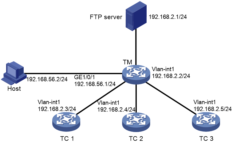
Network configuration
As shown in Figure 3, member 1, member 2, and member 3 belong to the same device type: MSR810-W-LM series. The IP address of the FTP server is 192.168.2.1. The FTP username is admin and the FTP password is admin.
Perform the following tasks to establish a SmartMC network and upgrade the configuration file on the member:
1. Configure the commander and members to automatically establish a SmartMC network.
2. Configure interface GigabitEthernet 1/0/1 as the outgoing interface for the SmartMC network.
3. Create a SmartMC group and add the members to the group.
4. Upgrade the configuration file on all members in the SmartMC group.
5. Save configuration file startup.cfg on the FTP server.
Procedure
1. Configure TC 1:
# Configure VLAN-interface 1.
<TC1> system-view
[TC1] interface vlan-interface 1
[TC1-Vlan-interface1] ip address 192.168.2.3 24
[TC1-Vlan-interface1] quit
# Enable HTTP and HTTPS.
[TC1] ip http enable
[TC1] ip https enable
# Enable the Telnet service.
[TC1] telnet server enable
# Enable NETCONF over SOAP over HTTP.
[TC1] netconf soap http enable
# Enable LLDP globally.
[TC1] lldp global enable
# Create a user. Set the username and password to admin, add the telnet, http, and https service types, and authorize the user to use the network-admin user role.
[TC1] local-user admin
[TC1-luser-manage-admin] password simple admin
[TC1-luser-manage-admin] service-type telnet http https
[TC1-luser-manage-admin] authorization-attribute user-role network-admin
[TC1-luser-manage-admin] quit
# Set scheme authentication for VTY user lines 0 to 63.
[TC1] line vty 0 63
[TC1-line-vty0-63] authentication-mode scheme
[TC1-line-vty0-63] quit
# Enable SmartMC and set the device role to member.
[TC1] smartmc tc enable
2. Configure TC 2 and TC 3 in the same way TC 1 is configured. (Details not shown.)
3. Configure the TM:
# Configure GigabitEthernet 1/0/1.
<TM> system-view
[TM] interface gigabitethernet 1/0/1
[TM-GigabitEthernet1/0/1] port link-mode route
[TM-GigabitEthernet1/0/1] ip address 192.168.52.2 24
[TM-GigabitEthernet1/0/1] quit
# Configure VLAN-interface 1.
[TM] interface vlan-interface 1
[TM-Vlan-interface1] ip address 192.168.2.2 24
[TM-Vlan-interface1] quit
# Enable HTTP and HTTPS.
[TM] ip http enable
[TM] ip https enable
# Enable the Telnet service.
[TM] telnet server enable
# Enable NETCONF over SOAP over HTTP.
[TM] netconf soap http enable
# Enable LLDP globally.
[TM] lldp global enable
# Create a user. Set the username and password to admin, add the telnet, http, and https service types, and authorize the user to use the network-admin user role.
[TM] local-user admin
[TM-luser-manage-admin] password simple admin
[TM-luser-manage-admin] service-type telnet http https
[TM-luser-manage-admin] authorization-attribute user-role network-admin
[TM-luser-manage-admin] quit
# Set scheme authentication for VTY user lines 0 to 63.
[TM] line vty 0 63
[TM-line-vty0-63] authentication-mode scheme
[TM-line-vty0-63] quit
# Enable SmartMC, set the device role to commander, and set both the username and password (plaintext) to admin.
[TM] smartmc tm username admin password simple admin enable
# Specify GigabitEthernet 1/0/1 as the outgoing interface.
[TM] interface gigabitethernet 1/0/1
[TM-GigabitEthernet1/0/1] smartmc outbound
[TM-GigabitEthernet1/0/1] quit
# Set the FTP server IP address, username, and plaintext password to 192.168.2.1, admin, and admin, respectively.
[TM] smartmc ftp-server 192.168.2.1 username admin password simple admin
# Create SmartMC group S1 and enter its view.
[TM] smartmc group S1
# Create an IP address match criterion to add all members in the specified network segment to SmartMC group S1.
[TM-smartmc-group-S1] match ip-address 192.168.2.0 24
# Specify the upgrade configuration file startup.cfg for SmartMC group S1.
[TM-smartmc-group-S1] startup-configuration startup.cfg
[TM-smartmc-group-S1] quit
# Upgrade the configuration file on all TCs in SmartMC group S1.
[TM] smartmc upgrade startup-configuration group S1 startup.cfg
Verifying the configuration
# Display brief information about all members after the SmartMC network is established.
[TM] display smartmc tc
TCID DeviceType IpAddress MacAddress Status Version Sysname
1 MSR810-W-LM 192.168.2.3 201c-e7c3-0300 Normal R0707 S1
2 MSR810-W-LM 192.168.2.4 201c-e7c3-0301 Normal R0707 S2
3 MSR810-W-LM 192.168.2.5 201c-e7c3-0302 Normal R0707 S3
# Display the configuration file upgrade status on the members.
<TM> display smartmc upgrade status
ID IpAddress MacAddress Status UpdateTime UpdateFile
1 192.168.2.3 201c-e7c3-0300 Finished Immediately startup.cfg
2 192.168.2.4 201c-e7c3-0301 Finished Immediately startup.cfg
3 192.168.2.5 201c-e7c3-0302 Finished Immediately startup.cfg