- Table of Contents
- Related Documents
-
| Title | Size | Download |
|---|---|---|
| 04-FR QoS configuration | 176.90 KB |
Contents
Restrictions: Hardware compatibility with FR QoS
Restrictions and guidelines: FR QoS configuration
Configuring PVC queuing as FIFO
Configuring an FR DE rule list
Configuring Frame Relay FRF.12 fragmentation for an FR class
Display and maintenance commands for FR QoS
Configuring FR QoS
About FR QoS
FR QoS application
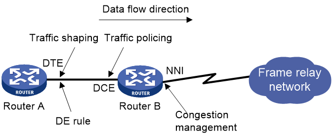
On an FR interface, you can use generic QoS services to perform interface-based traffic shaping, traffic policing, congestion management, and congestion avoidance. You can also use FR QoS to implement virtual circuit-based QoS, including FR traffic shaping (FRTS), FR traffic policing (FRTP), FR congestion management, FR discard eligibility (DE) rule list, and FR queuing management.
FR QoS works on a per-PVC basis and is more flexible than generic QoS. For more information about Frame Relay, see Layer 2—WAN Configuration Guide.
Figure 1 FR QoS implementation
FR QoS parameters
FR QoS uses the following parameters:
· CIR ALLOW—Average transmission rate guaranteed on a PVC when no congestion occurs.
· CIR—Minimum transmission rate guaranteed on a PVC even if congestion occurs in the network.
· CBS—Size of traffic that a PVC is committed to transmitting within the interval of Tc when congestion occurs in the network.
· EBS—Maximum size of traffic that can exceed CBS on a PVC within the interval of Tc. When congestion occurs in the network, the traffic of the EBS size is dropped first. Transmitting traffic of the EBS size is not guaranteed by the FR network.
FRTS
Functionality
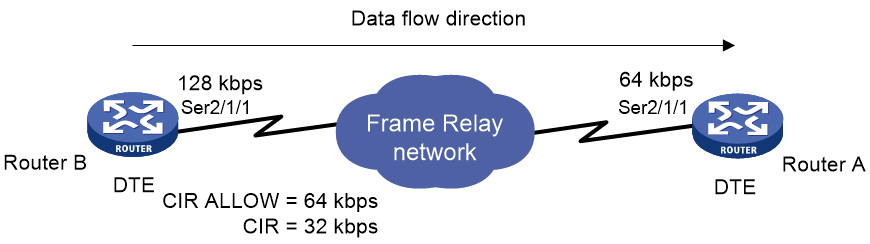
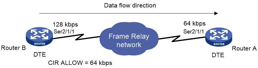
FRTS limits the outgoing traffic rate and smoothes bursts for PVCs. Then, PVCs can transmit traffic at a constant rate. FRTS applies to the outgoing interface of a switch. You can use FRTS to remove the bottleneck created when the input rate of a device is slower than the output rate of the sending device.
As shown in Figure 2:
· Router B transmits packets to Router A at 128 kbps.
· The maximum interface rate of Router A is only 64 kbps.
The disparity in traffic rate creates a bottleneck on the interface that connects Router A to the FR network.
To avoid packet loss, you can configure FRTS with the CIR ALLOW 64 kbps and the CIR 32 kbps on the outgoing interface Serial 2/1/1 of Router B. Then, the interface can transmit packets constantly at 64 kbps when no congestion occurs. Even if congestion occurs in the network, Router B can still transmit packets at the rate of 32 kbps.
FRTS uses the parameters CIR ALLOW, CIR, CBS, and EBS for traffic shaping. FR PVCs can transmit packets at the rate of CIR ALLOW when no congestion occurs. In the case of bursty packets, FRTS allows an FR PVC to transmit packets at a rate exceeding the CIR ALLOW.
When congestion occurs, the DCE sends FR packets with the BECN bit set to 1 to the DTE. Then, the DTE reduces its transmission rate from CIR ALLOW to CIR. If the DTE does not receive an FR packet with the BECN bit set to 1 within 125 milliseconds, it increases its transmission rate back to CIR ALLOW.
How FRTS works
FRTS is implemented by using token buckets. The meanings of the related parameters in the protocol are modified as required by the actual algorithm and principles. Figure 3 shows how a token bucket works.
Figure 3 How a token bucket works
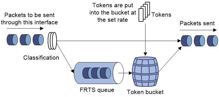
In the token bucket method, packets requiring traffic control are processed in the token bucket as follows before transmission:
· If the token bucket has enough tokens (in bits) for sending these packets, the packets are allowed to pass.
· If the token bucket does not have enough tokens for sending these packets, these packets are put into the FR class queue.
· Once the token bucket has enough tokens, the packets are taken out of the FR class queue for transmission.
In this way, you can control the rate of a class of packets. .
The FR protocol-provisioned parameters correspond to the FRTS parameters as follows:
· The sum of CBS and EBS equals the token bucket size.
· The CIR ALLOW defines the number of tokens put into the token bucket per second.
For efficiency, the FRTS introduces the concept of dynamic Tc (Tc=packet size/CIR ALLOW). The Tc can be dynamic adjusted depending on the transmitted packet size. The device allocates the required tokens to the current packets waiting for transmission within the latest Tc regardless of the packet size (smaller than 1500 bytes).
For example, send an 800-byte packet. If the CIR ALLOW of 64000 kbps, it takes Tc=6400/64000=0.1 second (100 ms) to put the required tokens into the token bucket. The packet is transmitted successfully if 6400 bits of tokens are put into the token bucket within 100 ms.
FRTP
FRTP monitors the traffic entering the network from each PVC and limits the traffic to specified traffic parameters. If the traffic on a PVC exceeds the user-defined threshold, the device takes action to conserve network resources.
Figure 4 FR traffic policing implementation
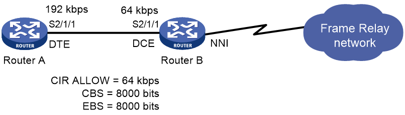
As shown in Figure 4, Router A on the user side transmits packets at the rate of 192 kbps to Router B on the switching side. To provide Router A with only 64 kbps of bandwidth, the FR traffic policing settings in the figure are used on the DCE side of Router B.
· When the traffic from Router A is smaller than the CBS, Router B forwards the packets without any other processing.
· When the traffic from Router A is larger than the CBS and smaller than EBS + CBS, the packets can be transmitted. However, for those packets of the traffic that exceeds the CBS, Router B sets the DE bit in the FR header to 1.
· When the traffic from Router A is larger than CBS + EBS, Router B performs the following operations:
¡ Transmits the traffic that is equal to CBS + EBS.
¡ Sets the DE bit in the FR header to 1 for the traffic that exceeds the CBS.
¡ Drops the traffic that exceeds CBS + EBS.
FR queuing
FR queuing includes PVC queuing and interface queuing. Figure 5 shows the relationship between PVC queuing and interface queuing.
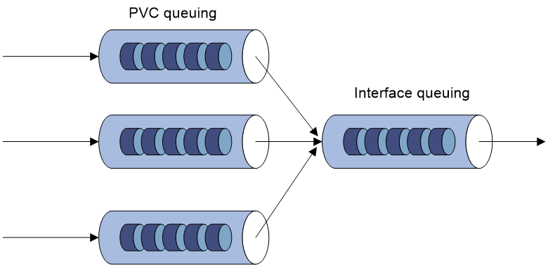
The device schedules packets by using PVC queuing before the device schedules them by using interface queuing.
PVC queuing takes effect only when FRTS is enabled.
FR interface queuing
The following queuing mechanisms are available on FR interfaces:
· FIFO.
· PVC PQ.
For more information about FIFO and PQ, see "Configuring congestion management."
PVC PQ has four queues (top, middle, normal, and bottom queues, in the descending priority order). The packets from one PVC are assigned to the same priority queue. PVC PQ dequeues and sends packets in the high-priority queue and then packets in the low-priority queue. The priority queue for a PVC is configured in the FR class associated with the PVC.
FR PVC queuing
After FRTS is enabled on an FR interface, each PVC on the interface has a queuing mechanism.
The following queuing mechanisms are available on FR PVCs:
· CBQ.
· CQ.
· FIFO.
· PQ.
· RTPQ.
· WFQ.
Only RTPQ can coexist with another queuing mechanism on a PVC. For information about queuing mechanisms, see "Configuring congestion management."
FR DE rule list
In an FR network, packets with the DE bits set to 1 are dropped first when congestion occurs. DE rule lists are applied on the FR PVCs of a device. An DE rule list can contain multiple DE rules. If a packet transmitted over the PVC matches the rules in the DE rule list, its DE bit is set to 1.
Restrictions: Hardware compatibility with FR QoS
|
Hardware |
FR QoS compatibility |
|
MSR810, MSR810-W, MSR810-W-DB, MSR810-LM, MSR810-W-LM, MSR810-10-PoE, MSR810-LM-HK, MSR810-W-LM-HK, MSR810-LM-CNDE-SJK, MSR810-CNDE-SJK |
No |
|
MSR810-LMS, MSR810-LUS |
Yes |
|
MSR810-LMS-EA, MSR810-LME |
No |
|
MSR2600-6-X1, MSR2600-10-X1 |
Yes |
|
MSR 2630 |
Yes |
|
MSR3600-28, MSR3600-51 |
Yes |
|
MSR3600-28-SI, MSR3600-51-SI |
Yes |
|
MSR3600-28-X1, MSR3600-28-X1-DP, MSR3600-51-X1, MSR3600-51-X1-DP |
Yes |
|
MSR3610-I-DP, MSR3610-IE-DP, MSR3610-IE-ES, MSR3610-IE-EAD |
Yes |
|
MSR3610-X1, MSR3610-X1-DP, MSR3610-X1-DC, MSR3610-X1-DP-DC |
Yes |
|
MSR 3610, MSR 3620, MSR 3620-DP, MSR 3640, MSR 3660 |
Yes |
|
MSR3610-G, MSR3620-G |
No |
|
Hardware |
FR QoS compatibility |
|
MSR810-W-WiNet, MSR810-LM-WiNet |
No |
|
MSR830-4LM-WiNet |
No |
|
MSR830-5BEI-WiNet, MSR830-6EI-WiNet, MSR830-10BEI-WiNet |
No |
|
MSR830-6BHI-WiNet, MSR830-10BHI-WiNet |
No |
|
MSR2600-6-WiNet, MSR2600-10-X1-WiNet |
Yes |
|
MSR2630-WiNet |
Yes |
|
MSR3600-28-WiNet |
Yes |
|
MSR3610-X1-WiNet |
Yes |
|
MSR3610-WiNet, MSR3620-10-WiNet, MSR3620-DP-WiNet, MSR3620-WiNet, MSR3660-WiNet |
Yes |
|
Hardware |
FR QoS compatibility |
|
MSR2630-XS |
Yes |
|
MSR3600-28-XS |
Yes |
|
MSR3610-XS |
Yes |
|
MSR3620-XS |
Yes |
|
MSR3610-I-XS |
Yes |
|
MSR3610-IE-XS |
Yes |
|
Hardware |
FR QoS compatibility |
|
MSR810-LM-GL |
No |
|
MSR810-W-LM-GL |
No |
|
MSR830-6EI-GL |
No |
|
MSR830-10EI-GL |
No |
|
MSR830-6HI-GL |
No |
|
MSR830-10HI-GL |
No |
|
MSR2600-6-X1-GL |
Yes |
|
MSR3600-28-SI-GL |
Yes |
Restrictions and guidelines: FR QoS configuration
To configure FRTS, FRTP, FR queuing, or FRF.12 fragmentation, perform the following tasks:
1. Create a FR class.
2. Configure QoS parameters for the FR class.
3. Associate the FR class with an interface or PVC.
A QoS-capable FR PVC selects an FR class in the following order:
1. The FR class associated with the PVC.
2. The FR class associated with the FR interface of the PVC.
Different PVCs can be associated with one FR class or different FR classes.
FR QoS tasks at a glance
To configure FR QoS, perform the following tasks:
· Configuring an FR DE rule list
· Configuring Frame Relay FRF.12 fragmentation for an FR class
Configuring FRTS
Restrictions and guidelines
FRTS applies to the outgoing FR packets. It is typically configured on DTEs.
You can use the cbs, ebs, and cir allow commands to set both the inbound and outbound parameters for an FR class. However, only the outbound parameters take effect.
Procedure
1. Enter system view.
system-view
2. Create an FR class and enter FR class view.
fr class class-name
3. (Optional.) Configure FRTS parameters.
¡ Set the CBS for the FR class.
cbs [ inbound | outbound ] committed-burst-size
The default setting is 56000 bits.
¡ Set the CIR for the FR class.
cir committed-information-rate
The default setting is 56000 bps.
¡ Set the CIR ALLOW for the FR class.
cir allow [ inbound | outbound ] committed-information-rate
The default setting is 56000 bps.
¡ Set the EBS for the FR class.
ebs [ inbound | outbound ] excess-burst-size
The default setting is 0 bits.
¡ Enable FRTS adaptation.
traffic-shaping adaptation { becn | interface-congestion number }
By default, FRTS adaptation is disabled.
¡ Set the FRTS adaptation percentage.
traffic-shaping adaptation percentage number
The default setting is 25%.
4. Return to system view.
quit
5. Associate the FR class with an FR interface or PVC.
¡ Execute the following commands in sequence to associate the FR class with an FR interface:
interface interface-type interface-number
link-protocol fr
fr-class class-name
¡ Execute the following commands in sequence to associate the FR class with a PVC:
interface interface-type interface-number
link-protocol fr
fr dlci dlci-number
fr-class class-name
By default, an FR class is not associated with any FR interface or PVC.
Configuring FRTP
Restrictions and guidelines
When you configure FRTP, follow these restrictions and guidelines:
· FRTP is applied to the interfaces receiving FR packets and can only be applied to the DCE of an FR network.
· You can use the cbs, ebs, and cir allow commands to set both inbound and outbound parameters for an FR class. However, only inbound parameters take effect.
Procedure
1. Enter system view.
system-view
2. Create an FR class and enter FR class view.
fr class class-name
3. (Optional.) Configure FRTP parameters.
¡ Set the CBS for the FR class.
cbs [ inbound | outbound ] committed-burst-size
The default setting is 56000 bits.
¡ Set CIR ALLOW for the FR class.
cir allow [ inbound | outbound ] committed-information-rate
The default setting is 56000 bps.
¡ Set the EBS for the FR class.
ebs [ inbound | outbound ] excess-burst-size
The default setting is 0 bits.
4. Return to system view.
quit
5. Associate the FR class with an FR interface or PVC.
¡ Execute the following commands in sequence to associate the FR class with an FR interface:
interface interface-type interface-number
link-protocol fr
fr-class class-name
¡ Execute the following commands in sequence to associate the FR class with a PVC:
interface interface-type interface-number
link-protocol fr
fr dlci dlci-number
fr-class class-name
By default, an FR class is not associated with any FR interface or PVC.
Configuring FR queuing
About FR queuing
By configuring FR queuing, you can perform congestion management on FR PVCs or FR interfaces. For more information about congestion management, see "Configuring congestion management."
Configuring PVC queuing as FIFO
Restrictions and guidelines
RTPQ can coexist with another queuing mechanism. However, any two queuing mechanisms other than RTPQ cannot coexist in an FR class.
Procedure
1. Enter system view.
system-view
2. Create an FR class and enter FR class view.
fr class class-name
3. (Optional.) Configure a PVC queuing mechanism.
¡ Configure FIFO:
fifo
queue-length queue-length
By default, the queue length is 75 packets.
By default, FIFO is used.
4. Return to system view.
quit
5. Associate the FR class with an FR interface or PVC.
¡ Execute the following commands in sequence to associate the FR class with an FR interface:
interface interface-type interface-number
link-protocol fr
fr-class class-name
¡ Execute the following commands in sequence to associate the FR class with a PVC:
interface interface-type interface-number
link-protocol fr
fr dlci dlci-number
fr-class class-name
By default, an FR class is not associated with any FR interface or PVC.
Configuring an FR DE rule list
Restrictions and guidelines
Up to 10 DE rule lists can be applied on a device. A DE rule list can be configured with up to 100 DE rules.
Procedure
1. Enter system view.
system-view
2. Configure a DE rule list.
¡ Create a DE rule list and add an interface-based DE rule:
fr del list-number inbound-interface interface-type interface-number
¡ Create a DE rule list and add an IP protocol-based DE rule:
fr del list-number protocol ip [ acl acl-number | fragments | greater-than min-number | less-than max-number | tcp-port tcpport-number | udp-port udpport-number ]
3. Enter FR interface view.
interface interface-type interface-number
4. Apply the DE rule list to an FR PVC of the interface.
fr de del list-number dlci dlci-number
By default, no DE rule list is applied to an FR PVC.
Configuring Frame Relay FRF.12 fragmentation for an FR class
Restrictions and guidelines
FRTS and FRF.12 fragmentation are mutually exclusive on an interface. For information about configuring FRF.12 fragmentation on an interface, see Layer 2—WAN Access Configuration Guide.
Procedure
1. Enter system view.
system-view
2. Create an FR class and enter FR class view.
fr class class-name
3. Enable Frame Relay FRF.12 fragmentation for the FR class.
fragment enable
By default, FRF.12 fragmentation is disabled for an FR class.
4. (Optional.) Set the fragment size allowed for the FR class.
fragment size
The default setting is 45 bytes.
5. Return to system view.
quit
6. Associate the FR class with an FR interface or PVC.
¡ Execute the following commands in sequence to associate the FR class with an FR interface:
interface interface-type interface-number
link-protocol fr
fr-class class-name
¡ Execute the following commands in sequence to associate the FR class with a PVC:
interface interface-type interface-number
link-protocol fr
fr dlci dlci-number
fr-class class-name
By default, an FR class is not associated with any FR interface or PVC.
Display and maintenance commands for FR QoS
Execute display commands in any view.
|
Task |
Command |
|
Display the associations between FR classes and interfaces (including subinterfaces and PVCs). |
display fr class-map [ fr-class class-name | interface interface-type interface-number ] |
|
Display the configuration and statistics for FR QoS. |
display fr pvc [ interface interface-type interface-number ] [ dlci dlci-number ] |
FR QoS configuration examples
Example: Configuring FRTS
Network configuration
As shown in Figure 6:
· The maximum rate of Serial 2/1/1 on Router A is 64 kbps.
· Router B sends packets to Router A at 128 kbps.
Configure FRTS on the outgoing interface Serial 2/1/1 of Router B to limit its transmission rate to an average of 64 kbps.
Procedure
# Create FR class 64k and configure its FRTS parameters.
<RouterB> system-view
[RouterB] fr class 64k
[RouterB-fr-class-64k] cir allow 64000
[RouterB-fr-class-64k] cir 32000
[RouterB-fr-class-64k] cbs 64000
[RouterB-fr-class-64k] ebs 32000
[RouterB-fr-class-64k] traffic-shaping adaptation becn
[RouterB-fr-class-64k] traffic-shaping adaptation percentage 20
[RouterB-fr-class-64k] quit
# Enable FR encapsulation and FRTS on Serial 2/1/1.
[RouterB] interface serial 2/1/1
[RouterB-Serial2/1/1] link-protocol fr
[RouterB-Serial2/1/1] fr traffic-shaping
# Create an FR PVC and associate FR class 64k with the FR PVC.
[RouterB-Serial2/1/1] fr dlci 16
[RouterB-Serial2/1/1-fr-dlci-16] fr-class 64k
Verifying the configuration
# Display the FR QoS configuration and statistics for the PVC with DLCI 16.
[RouterB-Serial2/1/1-fr-dlci-16] display fr pvc dlci 16
PVC information for interface Serial2/1/1 (DTE, physically up)
DLCI: 16 Type: Static Interface: Serial2/1/1
Encapsulation: IETF
Creation time: 2014/02/19 01:38:00 Status: Active
Input: 4 packets, 120 bytes, 0 dropped
Output: 4 packets, 120 bytes, 0 dropped
Traffic shaping: Active
CIR allow: 64000 bps CIR: 32000 bps
CBS: 64000 bits EBS: 32000 bits
Current CIR: 64000 bps
Output: 0 packets, 0 bytes, 0 dropped packets
Delayed: 0 packets, 0 bytes
Output queue: (Urgent queuing: Size/Length/Discards) 0/100/0
Output queue: (Protocol queuing: Size/Length/Discards) 0/500/0
Output queue: (FIFO queuing: Size/Length/Discards) 0/75/0
The output shows that traffic shaping is enabled and the CIR ALLOW is 64 kbps.