- Table of Contents
-
- 03-Layer 2 - LAN Switching Configuration Examples
- 01-H3C_MAC_Address_Table_Configuration_Examples
- 02-H3C_Ethernet_Link_Aggregation_Configuration_Examples
- 03-H3C_Port_Isolation_Configuration_Examples
- 04-H3C_Spanning_Tree_Configuration_Examples
- 05-H3C_VLAN_Configuration_Examples
- 06-H3C_MVRP_Configuration_Examples
- 07-H3C_QinQ_Configuration_Examples
- 08-H3C_VLAN_Mapping_Configuration_Examples
- 09-H3C_DRNI_Configuration_Examples
- 10-S-MLAG_Configuration_Examples
- Related Documents
-
| Title | Size | Download |
|---|---|---|
| 09-H3C_DRNI_Configuration_Examples | 217.47 KB |
|
|
|
H3C DRNI Configuration Examples |
|
|
|
|
|
|
Software version: Release 7585P05
Document version: 6W100-20200330
Copyright © 2020 New H3C Technologies Co., Ltd. All rights reserved.
No part of this manual may be reproduced or transmitted in any form or by any means without prior written consent of New H3C Technologies Co., Ltd.
Except for the trademarks of New H3C Technologies Co., Ltd., any trademarks that may be mentioned in this document are the property of their respective owners.
The information in this document is subject to change without notice.
Contents
Example: Configuring DRNI at the access layer
DRNI restrictions and guidelines
VRRP restrictions and guidelines
Example: Configuring DRNI at the distribution layer
DRNI restrictions and guidelines
VRRP restrictions and guidelines
Introduction
This document provides DRNI configuration examples.
Distributed Resilient Network Interconnect (DRNI) virtualizes two physical devices into one system for multichassis link aggregation. A remote aggregation system can connect to the member devices in the DRNI system through a multichassis link aggregation for node redundancy.
Prerequisites
The configuration examples were created and verified in a lab environment, and all the devices were started with the factory default configuration. When you are working on a live network, make sure you understand the potential impact of every command on your network.
The following information is provided based on the assumption that you have basic knowledge of DRNI.
Example: Configuring DRNI at the access layer
Network configuration
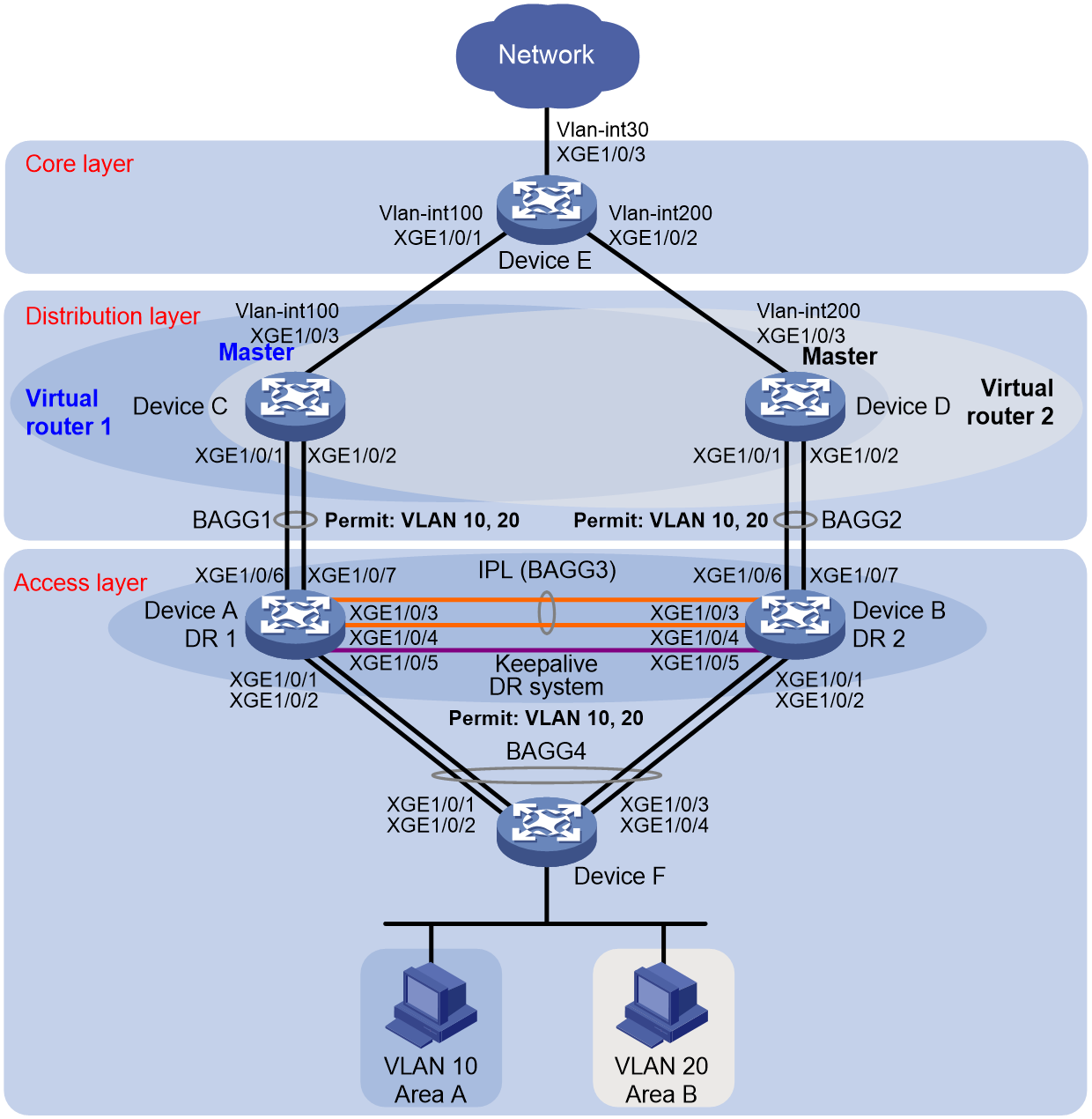
As shown in Figure 1:
· Configure Device A and Device B as a DR system to establish one multichassis aggregate link with Device F and one with Device C and Device D.
· Set up a keepalive link between Ten-GigabitEthernet 1/0/5 of Device A and Ten-GigabitEthernet 1/0/5 of Device B, and exclude the interfaces from the shutdown action by DRNI MAD.
· Configure two VRRP groups on Device C and Device D to provide gateway services for VLAN 10 and VLAN 20.
¡ Configure VRRP group 1 to provide gateway services for hosts in VLAN 10 (Area A). Add Device C and Device D to the group as the master and backup devices, respectively.
¡ Configure VRRP group 2 to provide gateway services for hosts in VLAN 20 (Area B). Add Device D and Device C to the group as the master and backup devices, respectively.
· Configure OSPF on Device C, Device D, and Device E for the hosts to communicate with external networks at Layer 3.
|
Device |
Interface |
IP address |
Device |
Interface |
IP address |
|
Device A |
XGE 1/0/5 |
1.1.1.1/24 |
Device B |
XGE 1/0/5 |
1.1.1.2/24 |
|
Device C |
VLAN-interface 100 |
100.1.1.1/24 |
Device D |
VLAN-interface 200 |
200.1.1.1/24 |
|
|
VLAN-interface 10 |
10.1.1.1/24 |
|
VLAN-interface 10 |
10.1.1.2/24 |
|
|
VLAN-interface 20 |
20.1.1.1/24 |
|
VLAN-interface 20 |
20.1.1.2/24 |
|
|
Virtual IP 1 |
10.1.1.100/24 |
|
Virtual IP 1 |
10.1.1.100/24 |
|
|
Virtual IP 2 |
20.1.1.100/24 |
|
Virtual IP 2 |
20.1.1.100/24 |
|
Device E |
VLAN-interface 100 |
100.1.1.2/24 |
|
|
|
|
|
VLAN-interface 200 |
200.1.1.2/24 |
|
|
|
|
|
VLAN-interface 30 |
30.1.1.1/24 |
|
|
|
Analysis
For the secondary DR device to monitor the state of the primary device, establish a Layer 3 keepalive link between the DR member devices.
To balance traffic between two VRRP gateway devices, you can assign them to two VRRP groups with different priorities. In this example, Device C is assigned a higher priority than Device D in VRRP group 1 so Device C can become the master in this group. Device D is assigned a higher priority than Device C in VRRP group 2 so Device D can become the master in this group.
Restrictions and guidelines
DRNI restrictions and guidelines
For the DR member devices to be identified as one DR system, you must configure the same DR system MAC address and DR system priority on them. In addition, assign different DR system numbers to the DR member devices.
A DR member device can have only one IPP.
For correct keepalive detection, you must exclude the interfaces used for keepalive detection from the shutdown action by DRNI MAD.
VRRP restrictions and guidelines
You cannot specify the virtual IP address as any of the following IP addresses:
· All-zero address (0.0.0.0).
· Broadcast address (255.255.255.255).
· Loopback address.
· IP address of other than Class A, Class B, and Class C.
· Invalid IP address (for example, 0.0.0.1).
Make sure the virtual IP address assigned to an IPv4 VRRP group is from the same subnet as the downlink interface IP addresses of its group members.
Procedures
Configuring Device A
# Configure DR system settings.
<DeviceA> system-view
[DeviceA] drni system-mac 1-1-1
Changing the system MAC address might flap the intra-portal link and cause DR system setup failure. Continue? [Y/N]:y
[DeviceA] drni system-number 1
Changing the system number might flap the intra-portal link and cause DR system setup failure. Continue? [Y/N]:y
[DeviceA] drni system-priority 123
Changing the system priority might flap the intra-portal link and cause DR system setup failure. Continue? [Y/N]:y
# Configure DR keepalive packet parameters.
[DeviceA] drni keepalive ip destination 1.1.1.2 source 1.1.1.1
# Configure Ten-GigabitEthernet 1/0/5 as a routed (Layer 3) interface and assign the interface an IP address. The IP address will be used as the source IP address of keepalive packets.
[DeviceA] interface ten-gigabitethernet 1/0/5
[DeviceA-Ten-GigabitEthernet1/0/5] port link-mode route
[DeviceA-Ten-GigabitEthernet1/0/5] ip address 1.1.1.1 24
[DeviceA-Ten-GigabitEthernet1/0/5] quit
# Exclude the interface used for DR keepalive detection (Ten-GigabitEthernet 1/0/5) from the shutdown action by DRNI MAD.
[DeviceA] drni mad exclude interface ten-gigabitethernet 1/0/5
# Create VLAN 10 and VLAN 20.
[DeviceA] vlan 10
[DeviceA-vlan10] quit
[DeviceA] vlan 20
[DeviceA-vlan20] quit
# Create Layer 2 dynamic aggregate interface Bridge-Aggregation 1.
[DeviceA] interface bridge-aggregation 1
[DeviceA-Bridge-Aggregation1] link-aggregation mode dynamic
[DeviceA-Bridge-Aggregation1] quit
# Assign Ten-GigabitEthernet 1/0/6 and Ten-GigabitEthernet 1/0/7 to aggregation group 1.
[DeviceA] interface ten-gigabitethernet 1/0/6
[DeviceA-Ten-GigabitEthernet1/0/6] port link-aggregation group 1
[DeviceA-Ten-GigabitEthernet1/0/6] quit
[DeviceA] interface ten-gigabitethernet 1/0/7
[DeviceA-Ten-GigabitEthernet1/0/7] port link-aggregation group 1
[DeviceA-Ten-GigabitEthernet1/0/7] quit
# Set the link type of Bridge-Aggregation 1 to trunk and assign it to VLAN 10 and VLAN 20.
[DeviceA] interface bridge-aggregation 1
[DeviceA-Bridge-Aggregation1] port link-type trunk
Configuring Ten-GigabitEthernet1/0/6 done.
Configuring Ten-GigabitEthernet1/0/7 done.
[DeviceA-Bridge-Aggregation1] port trunk permit vlan 10 20
Configuring Ten-GigabitEthernet1/0/6 done.
Configuring Ten-GigabitEthernet1/0/7 done.
[DeviceA-Bridge-Aggregation1] quit
# Create Layer 2 dynamic aggregate interface Bridge-Aggregation 3 and specify it as the IPP.
[DeviceA] interface bridge-aggregation 3
[DeviceA-Bridge-Aggregation3] link-aggregation mode dynamic
[DeviceA-Bridge-Aggregation3] port drni intra-portal-port 1
[DeviceA-Bridge-Aggregation3] quit
# Assign Ten-GigabitEthernet 1/0/3 and Ten-GigabitEthernet 1/0/4 to aggregation group 3.
[DeviceA] interface ten-gigabitethernet 1/0/3
[DeviceA-Ten-GigabitEthernet1/0/3] port link-aggregation group 3
[DeviceA-Ten-GigabitEthernet1/0/3] quit
[DeviceA] interface ten-gigabitethernet 1/0/4
[DeviceA-Ten-GigabitEthernet1/0/4] port link-aggregation group 3
[DeviceA-Ten-GigabitEthernet1/0/4] quit
# Set the link type of Bridge-Aggregation 3 to trunk and assign it to VLAN 10 and VLAN 20.
[DeviceA] interface bridge-aggregation 3
[DeviceA-Bridge-Aggregation3] port link-type trunk
Configuring Ten-GigabitEthernet1/0/3 done.
Configuring Ten-GigabitEthernet1/0/4 done.
[DeviceA-Bridge-Aggregation3] port trunk permit vlan 10 20
Configuring Ten-GigabitEthernet1/0/3 done.
Configuring Ten-GigabitEthernet1/0/4 done.
[DeviceA-Bridge-Aggregation3] quit
# Create Layer 2 dynamic aggregate interface Bridge-Aggregation 4 and assign it to DR group 4.
[DeviceA] interface bridge-aggregation 4
[DeviceA-Bridge-Aggregation4] link-aggregation mode dynamic
[DeviceA-Bridge-Aggregation4] port drni group 4
[DeviceA-Bridge-Aggregation4] quit
# Assign Ten-GigabitEthernet 1/0/1 and Ten-GigabitEthernet 1/0/2 to aggregation group 4.
[DeviceA] interface ten-gigabitethernet 1/0/1
[DeviceA-Ten-GigabitEthernet1/0/1] port link-aggregation group 4
[DeviceA-Ten-GigabitEthernet1/0/1] quit
[DeviceA] interface ten-gigabitethernet 1/0/2
[DeviceA-Ten-GigabitEthernet1/0/2] port link-aggregation group 4
[DeviceA-Ten-GigabitEthernet1/0/2] quit
# Set the link type of Bridge-Aggregation 4 to trunk and assign it to VLAN 10 and VLAN 20.
[DeviceA] interface bridge-aggregation 4
[DeviceA-Bridge-Aggregation4] port link-type trunk
Configuring Ten-GigabitEthernet1/0/1 done.
Configuring Ten-GigabitEthernet1/0/2 done.
[DeviceA-Bridge-Aggregation4] port trunk permit vlan 10 20
Configuring Ten-GigabitEthernet1/0/1 done.
Configuring Ten-GigabitEthernet1/0/2 done.
[DeviceA-Bridge-Aggregation4] quit
Configuring Device B
# Configure DR system settings.
<DeviceB> system-view
[DeviceB] drni system-mac 1-1-1
Changing the system MAC address might flap the intra-portal link and cause DR system setup failure. Continue? [Y/N]:y
[DeviceB] drni system-number 2
Changing the system number might flap the intra-portal link and cause DR system setup failure. Continue? [Y/N]:y
[DeviceB] drni system-priority 123
Changing the system priority might flap the intra-portal link and cause DR system setup failure. Continue? [Y/N]:y
# Configure DR keepalive packet parameters.
[DeviceB] drni keepalive ip destination 1.1.1.1 source 1.1.1.2
# Configure Ten-GigabitEthernet 1/0/5 as a routed (Layer 3) interface and assign the interface an IP address. The IP address will be used as the source IP address of keepalive packets.
[DeviceB] interface ten-gigabitethernet 1/0/5
[DeviceB-Ten-GigabitEthernet1/0/5] port link-mode route
[DeviceB-Ten-GigabitEthernet1/0/5] ip address 1.1.1.2 24
[DeviceB-Ten-GigabitEthernet1/0/5] quit
# Exclude the interface used for DR keepalive detection (Ten-GigabitEthernet 1/0/5) from the shutdown action by DRNI MAD.
[DeviceB] drni mad exclude interface ten-gigabitethernet 1/0/5
# Create VLAN 10 and VLAN 20.
[DeviceB] vlan 10
[DeviceB-vlan10] quit
[DeviceB] vlan 20
[DeviceB-vlan20] quit
# Create Layer 2 dynamic aggregate interface Bridge-Aggregation 2.
[DeviceB] interface bridge-aggregation 2
[DeviceB-Bridge-Aggregation2] link-aggregation mode dynamic
[DeviceB-Bridge-Aggregation2] quit
# Assign Ten-GigabitEthernet 1/0/6 and Ten-GigabitEthernet 1/0/7 to aggregation group 2.
[DeviceB] interface ten-gigabitethernet 1/0/6
[DeviceB-Ten-GigabitEthernet1/0/6] port link-aggregation group 2
[DeviceB-Ten-GigabitEthernet1/0/6] quit
[DeviceB] interface ten-gigabitethernet 1/0/7
[DeviceB-Ten-GigabitEthernet1/0/7] port link-aggregation group 2
[DeviceB-Ten-GigabitEthernet1/0/7] quit
# Set the link type of Bridge-Aggregation 2 to trunk and assign it to VLAN 10 and VLAN 20.
[DeviceB] interface bridge-aggregation 2
[DeviceB-Bridge-Aggregation2] port link-type trunk
Configuring Ten-GigabitEthernet1/0/6 done.
Configuring Ten-GigabitEthernet1/0/7 done.
[DeviceB-Bridge-Aggregation2] port trunk permit vlan 10 20
Configuring Ten-GigabitEthernet1/0/6 done.
Configuring Ten-GigabitEthernet1/0/7 done.
[DeviceB-Bridge-Aggregation2] quit
# Create Layer 2 dynamic aggregate interface Bridge-Aggregation 3 and specify it as the IPP.
[DeviceB] interface bridge-aggregation 3
[DeviceB-Bridge-Aggregation3] link-aggregation mode dynamic
[DeviceB-Bridge-Aggregation3] port drni intra-portal-port 1
[DeviceB-Bridge-Aggregation3] quit
# Assign Ten-GigabitEthernet 1/0/3 and Ten-GigabitEthernet 1/0/4 to aggregation group 3.
[DeviceB] interface ten-gigabitethernet 1/0/3
[DeviceB-Ten-GigabitEthernet1/0/3] port link-aggregation group 3
[DeviceB-Ten-GigabitEthernet1/0/3] quit
[DeviceB] interface ten-gigabitethernet 1/0/4
[DeviceB-Ten-GigabitEthernet1/0/4] port link-aggregation group 3
[DeviceB-Ten-GigabitEthernet1/0/4] quit
# Set the link type of Bridge-Aggregation 3 to trunk and assign it to VLAN 10 and VLAN 20.
[DeviceB] interface bridge-aggregation 3
[DeviceB-Bridge-Aggregation3] port link-type trunk
Configuring Ten-GigabitEthernet1/0/3 done.
Configuring Ten-GigabitEthernet1/0/4 done.
[DeviceB-Bridge-Aggregation3] port trunk permit vlan 10 20
Configuring Ten-GigabitEthernet1/0/3 done.
Configuring Ten-GigabitEthernet1/0/4 done.
[DeviceB-Bridge-Aggregation3] quit
# Create Layer 2 dynamic aggregate interface Bridge-Aggregation 4 and assign it to DR group 4.
[DeviceB] interface bridge-aggregation 4
[DeviceB-Bridge-Aggregation4] link-aggregation mode dynamic
[DeviceB-Bridge-Aggregation4] port drni group 4
[DeviceB-Bridge-Aggregation4] quit
# Assign Ten-GigabitEthernet 1/0/1 and Ten-GigabitEthernet 1/0/2 to aggregation group 4.
[DeviceB] interface ten-gigabitethernet 1/0/1
[DeviceB-Ten-GigabitEthernet1/0/1] port link-aggregation group 4
[DeviceB-Ten-GigabitEthernet1/0/1] quit
[DeviceB] interface ten-gigabitethernet 1/0/2
[DeviceB-Ten-GigabitEthernet1/0/2] port link-aggregation group 4
[DeviceB-Ten-GigabitEthernet1/0/2] quit
# Set the link type of Bridge-Aggregation 4 to trunk and assign it to VLAN 10 and VLAN 20.
[DeviceB] interface bridge-aggregation 4
[DeviceB-Bridge-Aggregation4] port link-type trunk
Configuring Ten-GigabitEthernet1/0/1 done.
Configuring Ten-GigabitEthernet1/0/2 done.
[DeviceB-Bridge-Aggregation4] port trunk permit vlan 10 20
Configuring Ten-GigabitEthernet1/0/1 done.
Configuring Ten-GigabitEthernet1/0/2 done.
[DeviceB-Bridge-Aggregation4] quit
Configuring Device C
# Create VLAN 10, VLAN 20, and VLAN 100.
<DeviceC> system-view
[DeviceC] vlan 10
[DeviceC-vlan10] quit
[DeviceC] vlan 20
[DeviceC-vlan20] quit
[DeviceC] vlan 100
# Assign Ten-GigabitEthernet 1/0/3 to VLAN 100.
[DeviceC] vlan 100
[DeviceC-vlan100] port ten-gigabitethernet 1/0/3
[DeviceC-vlan100] quit
# Create Layer 2 dynamic aggregate interface Bridge-Aggregation 1.
[DeviceC] interface bridge-aggregation 1
[DeviceC-Bridge-Aggregation1] link-aggregation mode dynamic
[DeviceC-Bridge-Aggregation1] quit
# Assign Ten-GigabitEthernet 1/0/1 and Ten-GigabitEthernet1/0/2 to aggregation group 1.
[DeviceC] interface range ten-gigabitethernet 1/0/1 to ten-gigabitethernet 1/0/2
[DeviceC-if-range] port link-aggregation group 1
[DeviceC-if-range] quit
# Set the link type of Bridge-Aggregation 1 to trunk and assign it to VLAN 10 and VLAN 20.
[DeviceC] interface bridge-aggregation 1
[DeviceC-Bridge-Aggregation1] port link-type trunk
Configuring Ten-GigabitEthernet1/0/1 done.
Configuring Ten-GigabitEthernet1/0/2 done.
[DeviceC-Bridge-Aggregation1] port trunk permit vlan 10 20
Configuring Ten-GigabitEthernet1/0/1 done.
Configuring Ten-GigabitEthernet1/0/2 done.
[DeviceC-Bridge-Aggregation1] quit
# Create uplink interface VLAN-interface 100 and assign it an IP address.
[DeviceC] interface vlan-interface 100
[DeviceC-Vlan-interface100] ip address 100.1.1.1 24
[DeviceC-Vlan-interface100] quit
# Create VLAN-interface 10 and VLAN-interface 20 and assign an IP address to each of them.
[DeviceC] interface vlan-interface 10
[DeviceC-vlan-interface10] ip address 10.1.1.1 24
[DeviceC-vlan-interface10] quit
[DeviceC] interface vlan-interface 20
[DeviceC-vlan-interface20] ip address 20.1.1.1 24
[DeviceC-vlan-interface20] quit
# Create VRRP group 1 on VLAN-interface 10 and set its virtual IP address to 10.1.1.100.
[DeviceC] interface vlan-interface 10
[DeviceC-Vlan-interface10] vrrp vrid 1 virtual-ip 10.1.1.100
# Set the priority of Device C to 200 for it to become the master in VRRP group 1.
[DeviceC-Vlan-interface10] vrrp vrid 1 priority 200
[DeviceC-Vlan-interface10] quit
# Create VRRP group 2 on VLAN-interface 20 and set its virtual IP address to 20.1.1.100.
[DeviceC] interface vlan-interface 20
[DeviceC-Vlan-interface20] vrrp vrid 2 virtual-ip 20.1.1.100
[DeviceC-vlan-interface20] quit
# Configure Device C to operate in preemptive mode in VRRP group 1. Set the preemption delay to 500 centiseconds to avoid frequent status switchover.
[DeviceC] interface vlan-interface 10
[DeviceC-Vlan-interface10] vrrp vrid 1 preempt-mode delay 500
[DeviceC-Vlan-interface10] quit
# Create track entry 1 to monitor the upstream link status of Ten-GigabitEthernet 1/0/3.
[DeviceC] track 1 interface ten-gigabitethernet 1/0/3
# Configure Device C in VRRP group 1 to monitor track entry 1, and decrease its priority by 150 when the track entry transits to Negative.
[DeviceC] interface vlan-interface 10
[DeviceC-Vlan-interface10] vrrp vrid 1 track 1 priority reduced 150
[DeviceC-Vlan-interface10] quit
# Configure OSPF.
[DeviceC] ospf
[DeviceC-ospf-1] area 0
[DeviceC-ospf-1-area-0.0.0.0] network 10.1.1.0 0.0.0.255
[DeviceC-ospf-1-area-0.0.0.0] network 20.1.1.0 0.0.0.255
[DeviceC-ospf-1-area-0.0.0.0] network 100.1.1.0 0.0.0.255
[DeviceC-ospf-1-area-0.0.0.0] quit
[DeviceC-ospf-1] quit
Configuring Device D
# Create VLAN 10, VLAN 20, and VLAN 200.
<DeviceD> system-view
[DeviceD] vlan 10
[DeviceD-vlan10] quit
[DeviceD] vlan 20
[DeviceD-vlan20] quit
[DeviceD] vlan 200
# Assign Ten-GigabitEthernet 1/0/3 to VLAN 200.
[DeviceD] vlan 200
[DeviceD-vlan200] port ten-gigabitethernet 1/0/3
[DeviceD-vlan200] quit
# Create Layer 2 dynamic aggregate interface Bridge-Aggregation 2.
[DeviceD] interface bridge-aggregation 2
[DeviceD-Bridge-Aggregation2] link-aggregation mode dynamic
[DeviceD-Bridge-Aggregation2] quit
# Assign Ten-GigabitEthernet 1/0/1 and Ten-GigabitEthernet 1/0/2 to aggregation group 2.
[DeviceD] interface range ten-gigabitethernet 1/0/1 to ten-gigabitethernet 1/0/2
[DeviceD-if-range] port link-aggregation group 2
[DeviceD-if-range] quit
# Set the link type of Bridge-Aggregation 2 to trunk and assign it to VLAN 10 and VLAN 20.
[DeviceD] interface bridge-aggregation 2
[DeviceD-Bridge-Aggregation2] port link-type trunk
Configuring Ten-GigabitEthernet1/0/1 done.
Configuring Ten-GigabitEthernet1/0/2 done.
[DeviceD-Bridge-Aggregation2] port trunk permit vlan 10 20
Configuring Ten-GigabitEthernet1/0/1 done.
Configuring Ten-GigabitEthernet1/0/2 done.
[DeviceD-Bridge-Aggregation2] quit
# Create uplink interface VLAN-interface 200 and assign it an IP address.
[DeviceD] interface vlan-interface 200
[DeviceD-Vlan-interface200] ip address 200.1.1.1 24
[DeviceD-Vlan-interface200] quit
# Create VLAN-interface 10 and VLAN-interface 20 and assign an IP address to each of them.
[DeviceD] interface vlan-interface 10
[DeviceD-vlan-interface10] ip address 10.1.1.2 24
[DeviceD-vlan-interface10] quit
[DeviceD] interface vlan-interface 20
[DeviceD-vlan-interface20] ip address 20.1.1.2 24
[DeviceD-vlan-interface20] quit
# Create VRRP group 1 on VLAN-interface 10 and set its virtual IP address to 10.1.1.100.
[DeviceD] interface vlan-interface 10
[DeviceD-Vlan-interface10] vrrp vrid 1 virtual-ip 10.1.1.100
[DeviceD-vlan-interface10] quit
# Create VRRP group 2 on VLAN-interface 20 and set its virtual IP address to 20.1.1.100.
[DeviceD] interface vlan-interface 20
[DeviceD-Vlan-interface20] vrrp vrid 2 virtual-ip 20.1.1.100
# Set the priority of Device D to 200 for it to become the master in VRRP group 2.
[DeviceD-Vlan-interface20] vrrp vrid 2 priority 200
# Configure Device D to operate in preemptive mode in VRRP group 2. Set the preemption delay to 500 centiseconds to avoid frequent status switchover.
[DeviceD-Vlan-interface20] vrrp vrid 2 preempt-mode delay 500
[DeviceD-Vlan-interface20] quit
# Create track entry 2 to monitor the upstream link status of Ten-GigabitEthernet 1/0/3.
[DeviceD] track 2 interface ten-gigabitethernet 1/0/3
# Configure Device D in VRRP group 2 to monitor track entry 2, and decrease its priority by 150 when the track entry transits to Negative.
[DeviceD] interface vlan-interface 20
[DeviceD-Vlan-interface20] vrrp vrid 2 track 2 priority reduced 150
[DeviceD-Vlan-interface20] quit
# Configure OSPF.
[DeviceD] ospf
[DeviceD-ospf-1] area 0
[DeviceD-ospf-1-area-0.0.0.0] network 10.1.1.0 0.0.0.255
[DeviceD-ospf-1-area-0.0.0.0] network 20.1.1.0 0.0.0.255
[DeviceD-ospf-1-area-0.0.0.0] network 200.1.1.0 0.0.0.255
[DeviceD-ospf-1-area-0.0.0.0] quit
[DeviceD-ospf-1] quit
Configuring Device E
# Create VLAN 100 and assign Ten-GigabitEthernet 1/0/1 to the VLAN.
<DeviceE> system-view
[DeviceE] vlan 100
[DeviceE-vlan100] port ten-gigabitethernet 1/0/1
[DeviceE-vlan100] quit
# Create VLAN-interface 100 and assign it an IP address.
[DeviceE] interface vlan-interface 100
[DeviceE-vlan-interface100] ip address 100.1.1.2 24
[DeviceE-vlan-interface100] quit
# Create VLAN 200 and assign Ten-GigabitEthernet 1/0/2 to the VLAN.
[DeviceE] vlan 200
[DeviceE-vlan200] port ten-gigabitethernet 1/0/2
[DeviceE-vlan200] quit
# Create VLAN-interface 200 and assign it an IP address.
[DeviceE] interface vlan-interface 200
[DeviceE-vlan-interface200] ip address 200.1.1.2 24
[DeviceE-vlan-interface200] quit
# Create VLAN 30 and assign Ten-GigabitEthernet 1/0/3 to the VLAN.
[DeviceE] vlan 30
[DeviceE-vlan30] port ten-gigabitethernet 1/0/3
[DeviceE-vlan30] quit
# Create VLAN-interface 30 and assign it an IP address.
[DeviceE] interface vlan-interface 30
[DeviceE-vlan-interface30] ip address 30.1.1.1 24
[DeviceE-vlan-interface30] quit
# Configure OSPF.
[DeviceD] ospf
[DeviceD-ospf-1] area 0
[DeviceD-ospf-1-area-0.0.0.0] network 100.1.1.0 0.0.0.255
[DeviceD-ospf-1-area-0.0.0.0] network 200.1.1.0 0.0.0.255
[DeviceD-ospf-1-area-0.0.0.0] network 30.1.1.0 0.0.0.255
[DeviceD-ospf-1-area-0.0.0.0] quit
[DeviceD-ospf-1] quit
Configuring Device F
# Create VLAN 10 and VLAN 20.
[DeviceF] vlan 10
[DeviceF-vlan10] quit
[DeviceF] vlan 20
[DeviceF-vlan20] quit
# Create Layer 2 dynamic aggregate interface Bridge-Aggregation 4.
[DeviceF] interface bridge-aggregation 4
[DeviceF-Bridge-Aggregation4] link-aggregation mode dynamic
[DeviceF-Bridge-Aggregation4] quit
# Assign Ten-GigabitEthernet 1/0/1 through Ten-GigabitEthernet 1/0/4 to aggregation group 4.
[DeviceF] interface range ten-gigabitethernet 1/0/1 to ten-gigabitethernet 1/0/4
[DeviceF-if-range] port link-aggregation group 4
[DeviceF-if-range] quit
# Set the link type of Bridge-Aggregation 4 to trunk and assign it to VLAN 10 and VLAN 20.
[DeviceF] interface bridge-aggregation 4
[DeviceF-Bridge-Aggregation4] port link-type trunk
Configuring Ten-GigabitEthernet1/0/1 done.
Configuring Ten-GigabitEthernet1/0/2 done.
Configuring Ten-GigabitEthernet1/0/3 done.
Configuring Ten-GigabitEthernet1/0/4 done.
[DeviceF-Bridge-Aggregation4] port trunk permit vlan 10 20
Configuring Ten-GigabitEthernet1/0/1 done.
Configuring Ten-GigabitEthernet1/0/2 done.
Configuring Ten-GigabitEthernet1/0/3 done.
Configuring Ten-GigabitEthernet1/0/4 done.
[DeviceF-Bridge-Aggregation4] quit
Verifying the configuration
# Verify that Device A and Device B have formed a DR system.
[DeviceA] display drni summary
Global consistency check : SUCCESS
Inconsistent type 1 global settings: -
IPP IPP ID State
BAGG3 1 UP
DR interface DR group ID State Check result Type 1 inconsistency
BAGG4 4 UP SUCCESS -
[DeviceA] display drni verbose
Flags: A -- Home_Gateway, B -- Neighbor_Gateway, C -- Other_Gateway,
D -- IPP_Activity, E -- DRCP_Timeout, F -- Gateway_Sync,
G -- Port_Sync, H -- Expired
IPP/IPP ID: BAGG3/1
State: UP
Local state/Peer state: ABDFG/ABDFG
Local Selected ports Index: 2, 5
Peer Selected ports Index: 2, 5
DR interface/DR group ID: BAGG4/4
State: UP
Local state/Peer state: ABDFG/ABDFG
Local Selected ports Index: 16385, 16388
Peer Selected ports Index: 32769, 32772
# Verify that all member ports of aggregation group 4 are in Selected state on Device F, which indicates a successful link aggregation between the DR system and Device F.
[DeviceF] display link-aggregation verbose
Loadsharing Type: Shar -- Loadsharing, NonS -- Non-Loadsharing
Port Status: S -- Selected, U -- Unselected, I -- Individual
Port: A -- Auto port, M -- Management port, R -- Reference port
Flags: A -- LACP_Activity, B -- LACP_Timeout, C -- Aggregation,
D -- Synchronization, E -- Collecting, F -- Distributing,
G -- Defaulted, H -- Expired
Aggregate Interface: Bridge-Aggregation4
Creation Mode: Manual
Aggregation Mode: Dynamic
Loadsharing Type: Shar
Management VLANs: None
System ID: 0x8000, 1eba-3c46-0300
Local:
Port Status Priority Index Oper-Key Flag
XGE1/0/1 S 32768 1 1 {ACDEF}
XGE1/0/2 S 32768 2 1 {ACDEF}
XGE1/0/3 S 32768 3 1 {ACDEF}
XGE1/0/4 S 32768 4 1 {ACDEF}
Remote:
Actor Priority Index Oper-Key SystemID Flag
XGE1/0/1(R) 32768 16385 40004 0x7b , 0001-0001-0001 {ACDEF}
XGE1/0/2 32768 16388 40004 0x7b , 0001-0001-0001 {ACDEF}
XGE1/0/3 32768 32769 40004 0x7b , 0001-0001-0001 {ACDEF}
XGE1/0/4 32768 32772 40004 0x7b , 0001-0001-0001 {ACDEF}
# Verify that Device C is the master in VRRP group 1 and Device D is the master in VRRP group 2.
[DeviceC] display vrrp
IPv4 Virtual Router Information:
Running mode : Standard
Total number of virtual routers : 2
Interface VRID State Running Adver Auth Virtual
Pri Timer Type IP
---------------------------------------------------------------------
Vlan10 1 Master 200 100 None 10.1.1.100
Vlan20 2 Backup 100 100 None 20.1.1.100
[DeviceD] display vrrp
IPv4 Virtual Router Information:
Running mode : Standard
Total number of virtual routers : 2
Interface VRID State Running Adver Auth Virtual
Pri Timer Type IP
---------------------------------------------------------------------
Vlan10 1 Backup 100 100 None 10.1.1.100
Vlan20 2 Master 200 100 None 20.1.1.100
# Verify that Device E has established OSPF neighbor relationships with Device C and Device D.
[DeviceE] display ospf peer
OSPF Process 1 with Router ID 200.1.1.2
Neighbor Brief Information
Area: 0.0.0.0
Router ID Address Pri Dead-Time State Interface
100.1.1.1 100.1.1.1 1 35 Full/BDR Vlan100
200.1.1.1 200.1.1.1 1 33 Full/BDR Vlan200
# Verify that the host in Area A can ping VLAN-interface 30 (30.1.1.1) on Device E.
C:\Documents and Settings\Administrator>ping 30.1.1.1
Pinging 30.1.1.1 with 32 bytes of data:
Reply from 30.1.1.1: bytes=32 time=1ms TTL=126
Reply from 30.1.1.1: bytes=32 time=1ms TTL=126
Reply from 30.1.1.1: bytes=32 time=1ms TTL=126
Reply from 30.1.1.1: bytes=32 time=1ms TTL=126
Ping statistics for 30.1.1.1:
Packets: Sent = 4, Received = 4, Lost = 0 (0% loss),
Approximate round trip times in milli-seconds:
Minimum = 1ms, Maximum = 1ms, Average = 1ms
Configuration files
· Device A:
#
vlan 10
#
vlan 20
#
interface Bridge-Aggregation1
port link-type trunk
port trunk permit vlan 1 10 20
link-aggregation mode dynamic
#
interface Bridge-Aggregation3
port link-type trunk
port trunk permit vlan 1 10 20
link-aggregation mode dynamic
port drni intra-portal-port 1
#
interface Bridge-Aggregation4
port link-type trunk
port trunk permit vlan 1 10 20
link-aggregation mode dynamic
port drni group 4
#
interface Ten-GigabitEthernet1/0/5
port link-mode route
ip address 1.1.1.1 255.255.255.0
#
interface Ten-GigabitEthernet1/0/1
port link-mode bridge
port link-type trunk
port trunk permit vlan 1 10 20
port link-aggregation group 4
#
interface Ten-GigabitEthernet1/0/2
port link-mode bridge
port link-type trunk
port trunk permit vlan 1 10 20
port link-aggregation group 4
#
interface Ten-GigabitEthernet1/0/3
port link-mode bridge
port link-type trunk
port trunk permit vlan 1 10 20
port link-aggregation group 3
#
interface Ten-GigabitEthernet1/0/4
port link-mode bridge
port link-type trunk
port trunk permit vlan 1 10 20
port link-aggregation group 3
#
interface Ten-GigabitEthernet1/0/6
port link-mode bridge
port link-type trunk
port trunk permit vlan 1 10 20
port link-aggregation group 1
#
interface Ten-GigabitEthernet1/0/7
port link-mode bridge
port link-type trunk
port trunk permit vlan 1 10 20
port link-aggregation group 1
#
drni system-mac 0001-0001-0001
drni system-number 1
drni system-priority 123
drni keepalive ip destination 1.1.1.2 source 1.1.1.1
#
drni mad exclude interface Ten-GigabitEthernet1/0/5
#
· Device B:
#
vlan 10
#
vlan 20
#
interface Bridge-Aggregation2
port link-type trunk
port trunk permit vlan 1 10 20
link-aggregation mode dynamic
#
interface Bridge-Aggregation3
port link-type trunk
port trunk permit vlan 1 10 20
link-aggregation mode dynamic
port drni intra-portal-port 1
#
interface Bridge-Aggregation4
port link-type trunk
port trunk permit vlan 1 10 20
link-aggregation mode dynamic
port drni group 4
#
interface Ten-GigabitEthernet1/0/5
port link-mode route
ip address 1.1.1.2 255.255.255.0
#
interface Ten-GigabitEthernet1/0/1
port link-mode bridge
port link-type trunk
port trunk permit vlan 1 10 20
port link-aggregation group 4
#
interface Ten-GigabitEthernet1/0/2
port link-mode bridge
port link-type trunk
port trunk permit vlan 1 10 20
port link-aggregation group 4
#
interface Ten-GigabitEthernet1/0/3
port link-mode bridge
port link-type trunk
port trunk permit vlan 1 10 20
port link-aggregation group 3
#
interface Ten-GigabitEthernet1/0/4
port link-mode bridge
port link-type trunk
port trunk permit vlan 1 10 20
port link-aggregation group 3
#
interface Ten-GigabitEthernet1/0/6
port link-mode bridge
port link-type trunk
port trunk permit vlan 1 10 20
port link-aggregation group 2
#
interface Ten-GigabitEthernet1/0/7
port link-mode bridge
port link-type trunk
port trunk permit vlan 1 10 20
port link-aggregation group 2
#
drni system-mac 0001-0001-0001
drni system-number 2
drni system-priority 123
drni keepalive ip destination 1.1.1.1 source 1.1.1.2
#
drni mad exclude interface Ten-GigabitEthernet1/0/5
#
· Device C:
#
ospf 1
area 0.0.0.0
network 10.1.1.0 0.0.0.255
network 20.1.1.0 0.0.0.255
network 100.1.1.0 0.0.0.255
#
vlan 10
#
vlan 20
#
vlan 100
#
interface Bridge-Aggregation1
port link-type trunk
port trunk permit vlan 1 10 20
link-aggregation mode dynamic
#
interface Vlan-interface10
ip address 10.1.1.1 255.255.255.0
vrrp vrid 1 virtual-ip 10.1.1.100
vrrp vrid 1 priority 200
vrrp vrid 1 preempt-mode delay 500
vrrp vrid 1 track 1 priority reduced 150
#
interface Vlan-interface20
ip address 20.1.1.1 255.255.255.0
vrrp vrid 2 virtual-ip 20.1.1.100
#
interface Vlan-interface100
ip address 100.1.1.1 255.255.255.0
#
interface Ten-GigabitEthernet1/0/1
port link-mode bridge
port link-type trunk
port trunk permit vlan 1 10 20
port link-aggregation group 1
#
interface Ten-GigabitEthernet1/0/2
port link-mode bridge
port link-type trunk
port trunk permit vlan 1 10 20
port link-aggregation group 1
#
interface Ten-GigabitEthernet1/0/3
port link-mode bridge
port access vlan 100
#
track 1 interface Ten-GigabitEthernet1/0/3
#
· Device D:
#
ospf 1
area 0.0.0.0
network 10.1.1.0 0.0.0.255
network 20.1.1.0 0.0.0.255
network 200.1.1.0 0.0.0.255
#
vlan 10
#
vlan 20
#
vlan 200
#
interface Bridge-Aggregation2
port link-type trunk
port trunk permit vlan 1 10 20
link-aggregation mode dynamic
#
interface Vlan-interface10
ip address 10.1.1.2 255.255.255.0
vrrp vrid 1 virtual-ip 10.1.1.100
#
interface Vlan-interface20
ip address 20.1.1.2 255.255.255.0
vrrp vrid 2 virtual-ip 20.1.1.100
vrrp vrid 2 priority 200
vrrp vrid 2 preempt-mode delay 500
vrrp vrid 2 track 2 priority reduced 150
#
interface Vlan-interface200
ip address 200.1.1.1 255.255.255.0
#
interface Ten-GigabitEthernet1/0/1
port link-mode bridge
port link-type trunk
port trunk permit vlan 1 10 20
port link-aggregation group 2
#
interface Ten-GigabitEthernet1/0/2
port link-mode bridge
port link-type trunk
port trunk permit vlan 1 10 20
port link-aggregation group 2
#
interface Ten-GigabitEthernet1/0/3
port link-mode bridge
port access vlan 200
#
track 2 interface Ten-GigabitEthernet1/0/3
#
· Device E:
#
ospf 1
area 0.0.0.0
network 30.1.1.0 0.0.0.255
network 100.1.1.0 0.0.0.255
network 200.1.1.0 0.0.0.255
#
vlan 30
#
vlan 100
#
vlan 200
#
interface Vlan-interface30
ip address 30.1.1.1 255.255.255.0
#
interface Vlan-interface100
ip address 100.1.1.2 255.255.255.0
#
interface Vlan-interface200
ip address 200.1.1.2 255.255.255.0
#
interface Ten-GigabitEthernet1/0/1
port link-mode bridge
port access vlan 100
#
interface Ten-GigabitEthernet1/0/2
port link-mode bridge
port access vlan 200
#
interface Ten-GigabitEthernet1/0/3
port link-mode bridge
port access vlan 30
#
· Device F:
#
vlan 10
#
vlan 20
#
interface Bridge-Aggregation4
port link-type trunk
port trunk permit vlan 1 10 20
link-aggregation mode dynamic
#
interface Ten-GigabitEthernet1/0/1
port link-mode bridge
port link-type trunk
port trunk permit vlan 1 10 20
port link-aggregation group 4
#
interface Ten-GigabitEthernet1/0/2
port link-mode bridge
port link-type trunk
port trunk permit vlan 1 10 20
port link-aggregation group 4
#
interface Ten-GigabitEthernet1/0/3
port link-mode bridge
port link-type trunk
port trunk permit vlan 1 10 20
port link-aggregation group 4
#
interface Ten-GigabitEthernet1/0/4
port link-mode bridge
port link-type trunk
port trunk permit vlan 1 10 20
port link-aggregation group 4
#
Example: Configuring DRNI at the distribution layer
Network configuration
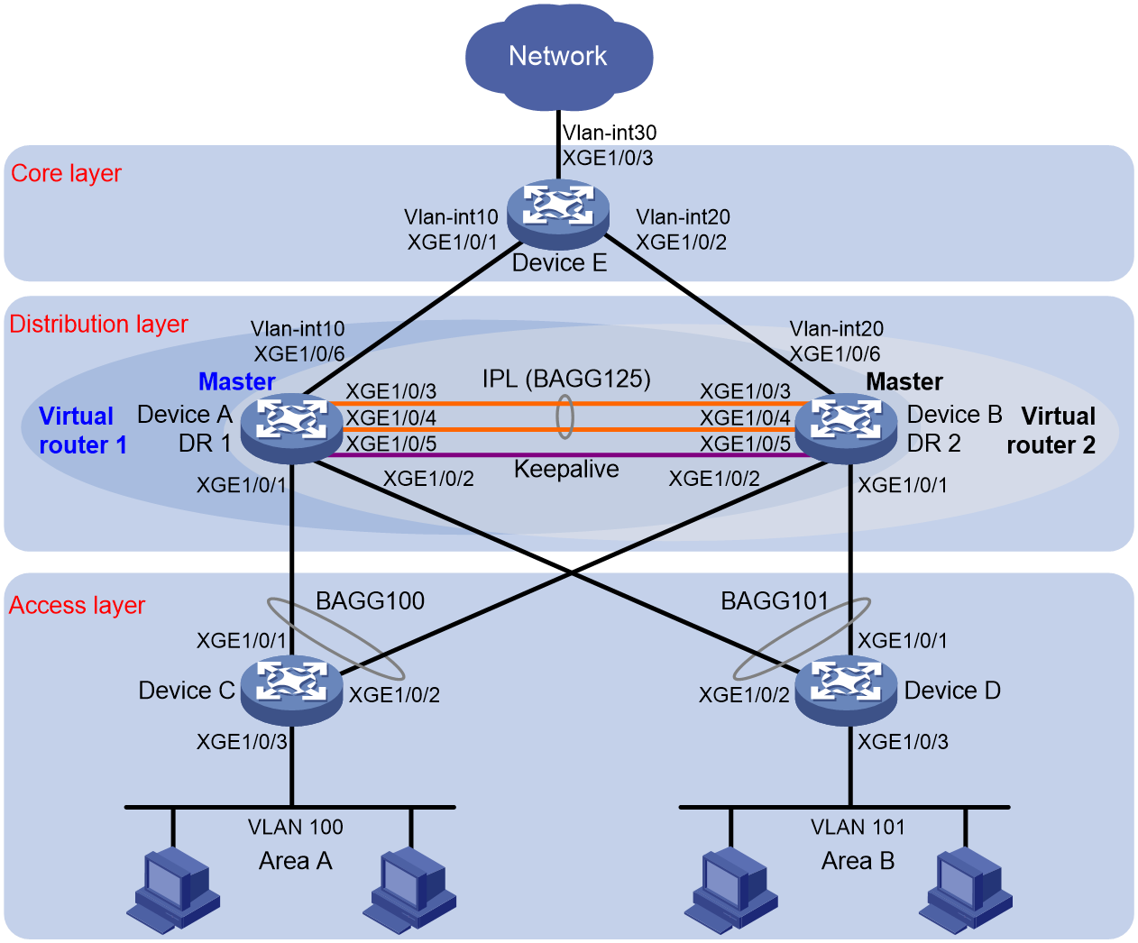
As shown in Figure 2:
· Configure Device A and Device B as a DR system to establish one multichassis aggregate link with Device C and Device D.
· Set up a keepalive link between Ten-GigabitEthernet 1/0/5 of Device A and Ten-GigabitEthernet 1/0/5 of Device B, and exclude the interfaces from the shutdown action by DRNI MAD.
· Configure two VRRP groups on Device A and Device B to provide gateway services for VLAN 100 and VLAN 101.
¡ Configure VRRP group 1 to provide gateway services for hosts in VLAN 100 (Area A). Add Device A and Device B to the group as the master and backup devices, respectively.
¡ Configure VRRP group 2 to provide gateway services for hosts in VLAN 101 (Area B). Add Device B and Device A to the group as the master and backup devices, respectively.
· Configure OSPF on Device A, Device B, and Device E for the hosts to communicate with external networks at Layer 3.
|
Device |
Interface |
IP address |
Device |
Interface |
IP address |
|
Device A |
XGE 1/0/5 |
1.1.1.1/24 |
Device B |
XGE 1/0/5 |
1.1.1.2/24 |
|
|
VLAN-interface 100 |
100.1.1.1/24 |
|
VLAN-interface 100 |
100.1.1.2/24 |
|
|
VLAN-interface 101 |
101.1.1.1/24 |
|
VLAN-interface 101 |
101.1.1.2/24 |
|
|
VLAN-interface 10 |
10.1.1.1/24 |
|
VLAN-interface 20 |
20.1.1.1/24 |
|
|
Virtual IP 1 |
100.1.1.100/24 |
|
Virtual IP 1 |
100.1.1.100/24 |
|
|
Virtual IP 2 |
101.1.1.100/24 |
|
Virtual IP 2 |
101.1.1.100/24 |
|
Device E |
VLAN-interface 10 |
10.1.1.2/24 |
|
|
|
|
|
VLAN-interface 20 |
20.1.1.2/24 |
|
|
|
|
|
VLAN-interface 30 |
30.1.1.1/24 |
|
|
|
Analysis
For the secondary DR device to monitor the state of the primary device, establish a Layer 3 keepalive link between the DR member devices.
To balance traffic between two VRRP gateway devices, you can assign them to two VRRP groups with different priorities. In this example, Device A is assigned a higher priority than Device B in VRRP group 1 so Device A can become the master in this group. Device B is assigned a higher priority than Device A in VRRP group 2 so Device B can become the master in this group.
Restrictions and guidelines
DRNI restrictions and guidelines
For the DR member devices to be identified as one DR system, you must configure the same DR system MAC address and DR system priority on them. In addition, assign different DR system numbers to the DR member devices.
A DR member device can have only one IPP.
For correct keepalive detection, you must exclude the interfaces used for keepalive detection from the shutdown action by DRNI MAD.
VRRP restrictions and guidelines
You cannot specify the virtual IP address as any of the following IP addresses:
· All-zero address (0.0.0.0).
· Broadcast address (255.255.255.255).
· Loopback address.
· IP address of other than Class A, Class B, and Class C.
· Invalid IP address (for example, 0.0.0.1).
Make sure the virtual IP address assigned to an IPv4 VRRP group is from the same subnet as the downlink interface IP addresses of its group members.
Procedures
Configuring Device A
# Configure DR system settings.
<DeviceA> system-view
[DeviceA] drni system-mac 1-1-1
Changing the system MAC address might flap the intra-portal link and cause DR system setup failure. Continue? [Y/N]:y
[DeviceA] drni system-number 1
Changing the system number might flap the intra-portal link and cause DR system setup failure. Continue? [Y/N]:y
[DeviceA] drni system-priority 123
Changing the system priority might flap the intra-portal link and cause DR system setup failure. Continue? [Y/N]:y
# Configure DR keepalive packet parameters.
[DeviceA] drni keepalive ip destination 1.1.1.2 source 1.1.1.1
# Configure Ten-GigabitEthernet 1/0/5 as a routed (Layer 3) interface and assign the interface an IP address. The IP address will be used as the source IP address of keepalive packets.
[DeviceA] interface ten-gigabitethernet 1/0/5
[DeviceA-Ten-GigabitEthernet1/0/5] port link-mode route
[DeviceA-Ten-GigabitEthernet1/0/5] ip address 1.1.1.1 24
[DeviceA-Ten-GigabitEthernet1/0/5] quit
# Exclude the interface used for DR keepalive detection (Ten-GigabitEthernet 1/0/5) from the shutdown action by DRNI MAD.
[DeviceA] drni mad exclude interface ten-gigabitethernet 1/0/5
# Create Layer 2 dynamic aggregate interface Bridge-Aggregation 125 and specify it as the IPP.
[DeviceA] interface bridge-aggregation 125
[DeviceA-Bridge-Aggregation125] link-aggregation mode dynamic
[DeviceA-Bridge-Aggregation125] port drni intra-portal-port 1
[DeviceA-Bridge-Aggregation125] quit
# Assign Ten-GigabitEthernet 1/0/3 and Ten-GigabitEthernet 1/0/4 to aggregation group 125.
[DeviceA] interface ten-gigabitethernet 1/0/3
[DeviceA-Ten-GigabitEthernet1/0/3] port link-aggregation group 125
[DeviceA-Ten-GigabitEthernet1/0/3] quit
[DeviceA] interface ten-gigabitethernet 1/0/4
[DeviceA-Ten-GigabitEthernet1/0/4] port link-aggregation group 125
[DeviceA-Ten-GigabitEthernet1/0/4] quit
# Create Layer 2 dynamic aggregate interface Bridge-Aggregation 100 and assign it to DR group 1.
[DeviceA] interface bridge-aggregation 100
[DeviceA-Bridge-Aggregation100] link-aggregation mode dynamic
[DeviceA-Bridge-Aggregation100] port drni group 1
[DeviceA-Bridge-Aggregation100] quit
# Assign Ten-GigabitEthernet 1/0/1 to aggregation group 100.
[DeviceA] interface ten-gigabitethernet 1/0/1
[DeviceA-Ten-GigabitEthernet1/0/1] port link-aggregation group 100
[DeviceA-Ten-GigabitEthernet1/0/1] quit
# Create Layer 2 dynamic aggregate interface Bridge-Aggregation 101 and assign it to DR group 2.
[DeviceA] interface bridge-aggregation 101
[DeviceA-Bridge-Aggregation101] link-aggregation mode dynamic
[DeviceA-Bridge-Aggregation101] port drni group 2
[DeviceA-Bridge-Aggregation101] quit
# Assign Ten-GigabitEthernet 1/0/2 to aggregation group 101.
[DeviceA] interface ten-gigabitethernet 1/0/2
[DeviceA-Ten-GigabitEthernet1/0/2] port link-aggregation group 101
[DeviceA-Ten-GigabitEthernet1/0/2] quit
# Create VLAN 10, VLAN 100, and VLAN 101.
[DeviceA] vlan 10
[DeviceA-vlan10] quit
[DeviceA] vlan 100
[DeviceA-vlan100] quit
[DeviceA] vlan 101
[DeviceA-vlan101] quit
# Assign Ten-GigabitEthernet 1/0/6 to VLAN 10.
[DeviceA] vlan 10
[DeviceA-vlan10] port ten-gigabitethernet 1/0/6
[DeviceA-vlan10] quit
# Set the link type of Bridge-Aggregation 100 to trunk and assign it to VLAN 100.
[DeviceA] interface bridge-aggregation 100
[DeviceA-Bridge-Aggregation100] port link-type trunk
Configuring Ten-GigabitEthernet1/0/1 done.
[DeviceA-Bridge-Aggregation100] port trunk permit vlan 100
Configuring Ten-GigabitEthernet1/0/1 done.
[DeviceA-Bridge-Aggregation100] quit
# Set the link type of Bridge-Aggregation 101 to trunk and assign it to VLAN 101.
[DeviceA] interface bridge-aggregation 101
[DeviceA-Bridge-Aggregation101] port link-type trunk
Configuring Ten-GigabitEthernet1/0/2 done.
[DeviceA-Bridge-Aggregation101] port trunk permit vlan 101
Configuring Ten-GigabitEthernet1/0/2 done.
[DeviceA-Bridge-Aggregation101] quit
# Set the link type of Bridge-Aggregation 125 to trunk and assign it to VLAN 100 and VLAN 101.
[DeviceA] interface bridge-aggregation 125
[DeviceA-Bridge-Aggregation125] port link-type trunk
Configuring Ten-GigabitEthernet1/0/3 done.
Configuring Ten-GigabitEthernet1/0/4 done.
[DeviceA-Bridge-Aggregation125] port trunk permit vlan 100 101
Configuring Ten-GigabitEthernet1/0/3 done.
Configuring Ten-GigabitEthernet1/0/4 done.
[DeviceA-Bridge-Aggregation125] quit
# Create VLAN-interface 10, VLAN-interface 100, and VLAN-interface 101 and assign an IP address to each of them.
[DeviceA] interface vlan-interface 10
[DeviceA-vlan-interface10] ip address 10.1.1.1 24
[DeviceA-vlan-interface10] quit
[DeviceA] interface vlan-interface 100
[DeviceA-vlan-interface100] ip address 100.1.1.1 24
[DeviceA-vlan-interface100] quit
[DeviceA] interface vlan-interface 101
[DeviceA-vlan-interface101] ip address 101.1.1.1 24
[DeviceA-vlan-interface101] quit
# Configure OSPF.
[DeviceA] ospf
[DeviceA-ospf-1] import-route direct
[DeviceA-ospf-1] area 0
[DeviceA-ospf-1-area-0.0.0.0] network 10.1.1.0 0.0.0.255
[DeviceA-ospf-1-area-0.0.0.0] network 100.1.1.0 0.0.0.255
[DeviceA-ospf-1-area-0.0.0.0] network 101.1.1.0 0.0.0.255
[DeviceA-ospf-1-area-0.0.0.0] quit
[DeviceA-ospf-1] quit
# Create VRRP group 1 on VLAN-interface 100 and set its virtual IP address to 100.1.1.100.
[DeviceA] interface vlan-interface 100
[DeviceA-Vlan-interface100] vrrp vrid 1 virtual-ip 100.1.1.100
# Set the priority of Device A to 200 for it to become the master in VRRP group 1.
[DeviceA-Vlan-interface100] vrrp vrid 1 priority 200
[DeviceA-Vlan-interface100] quit
# Create VRRP group 2 on VLAN-interface 101 and set its virtual IP address to 101.1.1.100.
[DeviceA] interface vlan-interface 101
[DeviceA-Vlan-interface101] vrrp vrid 2 virtual-ip 101.1.1.100
[DeviceA-Vlan-interface101] quit
# Configure Device A to operate in preemptive mode in VRRP group 1. Set the preemption delay to 500 centiseconds to avoid frequent status switchover.
[DeviceA] interface vlan-interface 100
[DeviceA-Vlan-interface100] vrrp vrid 1 preempt-mode delay 500
[DeviceA-Vlan-interface100] quit
# Create track entry 1 to monitor the upstream link status of Ten-GigabitEthernet 1/0/6.
[DeviceA] track 1 interface ten-gigabitethernet 1/0/6
# Configure Device A in VRRP group 1 to monitor track entry 1, and decrease its priority by 150 when the track entry transits to Negative.
[DeviceA] interface vlan-interface 100
[DeviceA-Vlan-interface100] vrrp vrid 1 track 1 priority reduced 150
[DeviceA-Vlan-interface100] quit
Configuring Device B
# Configure DR system settings.
<DeviceB> system-view
[DeviceB] drni system-mac 1-1-1
Changing the system MAC address might flap the intra-portal link and cause DR system setup failure. Continue? [Y/N]:y
[DeviceB] drni system-number 2
Changing the system number might flap the intra-portal link and cause DR system setup failure. Continue? [Y/N]:y
[DeviceB] drni system-priority 123
Changing the system priority might flap the intra-portal link and cause DR system setup failure. Continue? [Y/N]:y
# Configure DR keepalive packet parameters.
[DeviceB] drni keepalive ip destination 1.1.1.1 source 1.1.1.2
# Configure Ten-GigabitEthernet 1/0/5 as a routed (Layer 3) interface and assign the interface an IP address. The IP address will be used as the source IP address of keepalive packets.
[DeviceB] interface ten-gigabitethernet 1/0/5
[DeviceB-Ten-GigabitEthernet1/0/5] port link-mode route
[DeviceB-Ten-GigabitEthernet1/0/5] ip address 1.1.1.2 24
[DeviceB-Ten-GigabitEthernet1/0/5] quit
# Exclude the interface used for DR keepalive detection (Ten-GigabitEthernet 1/0/5) from the shutdown action by DRNI MAD.
[DeviceB] drni mad exclude interface ten-gigabitethernet 1/0/5
# Create Layer 2 dynamic aggregate interface Bridge-Aggregation 125 and specify it as the IPP.
[DeviceB] interface bridge-aggregation 125
[DeviceB-Bridge-Aggregation125] link-aggregation mode dynamic
[DeviceB-Bridge-Aggregation125] port drni intra-portal-port 1
[DeviceB-Bridge-Aggregation125] quit
# Assign Ten-GigabitEthernet 1/0/3 and Ten-GigabitEthernet 1/0/4 to aggregation group 125.
[DeviceB] interface ten-gigabitethernet 1/0/3
[DeviceB-Ten-GigabitEthernet1/0/3] port link-aggregation group 125
[DeviceB-Ten-GigabitEthernet1/0/3] quit
[DeviceB] interface ten-gigabitethernet 1/0/4
[DeviceB-Ten-GigabitEthernet1/0/4] port link-aggregation group 125
[DeviceB-Ten-GigabitEthernet1/0/4] quit
# Create Layer 2 dynamic aggregate interface Bridge-Aggregation 100 and assign it to DR group 1.
[DeviceB] interface bridge-aggregation 100
[DeviceB-Bridge-Aggregation100] link-aggregation mode dynamic
[DeviceB-Bridge-Aggregation100] port drni group 1
[DeviceB-Bridge-Aggregation100] quit
# Assign Ten-GigabitEthernet 1/0/2 to aggregation group 100.
[DeviceB] interface ten-gigabitethernet 1/0/2
[DeviceB-Ten-GigabitEthernet1/0/2] port link-aggregation group 100
[DeviceB-Ten-GigabitEthernet1/0/2] quit
# Create Layer 2 dynamic aggregate interface Bridge-Aggregation 101 and assign it to DR group 2.
[DeviceB] interface bridge-aggregation 101
[DeviceB-Bridge-Aggregation101] link-aggregation mode dynamic
[DeviceB-Bridge-Aggregation101] port drni group 2
[DeviceB-Bridge-Aggregation101] quit
# Assign Ten-GigabitEthernet 1/0/1 to aggregation group 101.
[DeviceB] interface ten-gigabitethernet 1/0/1
[DeviceB-Ten-GigabitEthernet1/0/1] port link-aggregation group 101
[DeviceB-Ten-GigabitEthernet1/0/1] quit
# Create VLAN 20, VLAN 100, and VLAN 101.
[DeviceB] vlan 20
[DeviceB-vlan20] quit
[DeviceB] vlan 100
[DeviceB-vlan100] quit
[DeviceB] vlan 101
[DeviceB-vlan101] quit
# Assign Ten-GigabitEthernet 1/0/6 to VLAN 20.
[DeviceB] vlan 20
[DeviceB-vlan20] port ten-gigabitethernet 1/0/6
[DeviceB-vlan20] quit
# Set the link type of Bridge-Aggregation 100 to trunk and assign it to VLAN 100.
[DeviceB] interface bridge-aggregation 100
[DeviceB-Bridge-Aggregation100] port link-type trunk
Configuring Ten-GigabitEthernet1/0/2 done.
[DeviceB-Bridge-Aggregation100] port trunk permit vlan 100
Configuring Ten-GigabitEthernet1/0/2 done.
[DeviceB-Bridge-Aggregation100] quit
# Set the link type of Bridge-Aggregation 101 to trunk and assign it to VLAN 101.
[DeviceB] interface bridge-aggregation 101
[DeviceB-Bridge-Aggregation101] port link-type trunk
Configuring Ten-GigabitEthernet1/0/1 done.
[DeviceB-Bridge-Aggregation101] port trunk permit vlan 101
Configuring Ten-GigabitEthernet1/0/1 done.
[DeviceB-Bridge-Aggregation101] quit
# Set the link type of Bridge-Aggregation 125 to trunk and assign it to VLAN 100 and VLAN 101.
[DeviceB] interface bridge-aggregation 125
[DeviceB-Bridge-Aggregation125] port link-type trunk
Configuring Ten-GigabitEthernet1/0/3 done.
Configuring Ten-GigabitEthernet1/0/4 done.
[DeviceB-Bridge-Aggregation125] port trunk permit vlan 100 101
Configuring Ten-GigabitEthernet1/0/3 done.
Configuring Ten-GigabitEthernet1/0/4 done.
[DeviceB-Bridge-Aggregation125] quit
# Create VLAN-interface 20, VLAN-interface 100, and VLAN-interface 101 and assign an IP address to each of them.
[DeviceB] interface vlan-interface 20
[DeviceB-vlan-interface20] ip address 20.1.1.1 24
[DeviceB-vlan-interface20] quit
[DeviceB] interface vlan-interface 100
[DeviceB-vlan-interface100] ip address 100.1.1.2 24
[DeviceB-vlan-interface100] quit
[DeviceB] interface vlan-interface 101
[DeviceB-vlan-interface101] ip address 101.1.1.2 24
[DeviceB-vlan-interface101] quit
# Configure OSPF.
[DeviceB] ospf
[DeviceB-ospf-1] import-route direct
[DeviceB-ospf-1] area 0
[DeviceB-ospf-1-area-0.0.0.0] network 20.1.1.0 0.0.0.255
[DeviceB-ospf-1-area-0.0.0.0] network 100.1.1.0 0.0.0.255
[DeviceB-ospf-1-area-0.0.0.0] network 101.1.1.0 0.0.0.255
[DeviceB-ospf-1-area-0.0.0.0] quit
[DeviceB-ospf-1] quit
# Create VRRP group 1 on VLAN-interface 100 and set its virtual IP address to 100.1.1.100.
[DeviceB] interface vlan-interface 100
[DeviceB-Vlan-interface100] vrrp vrid 1 virtual-ip 100.1.1.100
[DeviceB-Vlan-interface100] quit
# Create VRRP group 2 on VLAN-interface 101 and set its virtual IP address to 101.1.1.100.
[DeviceB] interface vlan-interface 101
[DeviceB-Vlan-interface101] vrrp vrid 2 virtual-ip 101.1.1.100
# Set the priority of Device B to 200 for it to become the master in VRRP group 2.
[DeviceB-Vlan-interface101] vrrp vrid 2 priority 200
# Configure Device B to operate in preemptive mode in VRRP group 2. Set the preemption delay to 500 centiseconds to avoid frequent status switchover.
[DeviceB-Vlan-interface101] vrrp vrid 2 preempt-mode delay 500
[DeviceB-Vlan-interface101] quit
# Create track entry 2 to monitor the upstream link status of Ten-GigabitEthernet 1/0/6.
[DeviceB] track 2 interface ten-gigabitethernet 1/0/6
# Configure Device B in VRRP group 2 to monitor track entry 2, and decrease its priority by 150 when the track entry transits to Negative.
[DeviceB] interface vlan-interface 101
[DeviceB-Vlan-interface101] vrrp vrid 2 track 2 priority reduced 150
[DeviceB-Vlan-interface101] quit
Configuring Device C
# Create VLAN 100.
[DeviceC] vlan 100
[DeviceC-vlan100] quit
# Assign Ten-GigabitEthernet 1/0/3 to VLAN 100.
[DeviceC] interface ten-gigabitethernet 1/0/3
[DeviceC-Ten-GigabitEthernet1/0/3] port access vlan 100
[DeviceC-Ten-GigabitEthernet1/0/3] quit
# Create Layer 2 dynamic aggregate interface Bridge-Aggregation 100.
<DeviceC> system-view
[DeviceC] interface bridge-aggregation 100
[DeviceC-Bridge-Aggregation100] link-aggregation mode dynamic
[DeviceC-Bridge-Aggregation100] quit
# Assign Ten-GigabitEthernet 1/0/1 and Ten-GigabitEthernet 1/0/2 to aggregation group 100.
[DeviceC] interface range ten-gigabitethernet 1/0/1 to ten-gigabitethernet 1/0/2
[DeviceC-if-range] port link-aggregation group 100
[DeviceC-if-range] quit
# Set the link type of Bridge-Aggregation 100 to trunk and assign it to VLAN 100.
[DeviceC] interface bridge-aggregation 100
[DeviceC-Bridge-Aggregation100] port link-type trunk
Configuring Ten-GigabitEthernet1/0/1 done.
Configuring Ten-GigabitEthernet1/0/2 done.
[DeviceC-Bridge-Aggregation100] port trunk permit vlan 100
Configuring Ten-GigabitEthernet1/0/1 done.
Configuring Ten-GigabitEthernet1/0/2 done.
[DeviceC-Bridge-Aggregation100] quit
Configuring Device D
# Create VLAN 101.
[DeviceD] vlan 101
[DeviceD-vlan101] quit
# Assign Ten-GigabitEthernet 1/0/3 to VLAN 101.
[DeviceD] interface ten-gigabitethernet 1/0/3
[DeviceD-Ten-GigabitEthernet1/0/3] port access vlan 101
[DeviceD-Ten-GigabitEthernet1/0/3] quit
# Create Layer 2 dynamic aggregate interface Bridge-Aggregation 101.
<DeviceD> system-view
[DeviceD] interface bridge-aggregation 101
[DeviceD-Bridge-Aggregation101] link-aggregation mode dynamic
[DeviceD-Bridge-Aggregation101] quit
# Assign Ten-GigabitEthernet 1/0/1 and Ten-GigabitEthernet 1/0/2 to aggregation group 101.
[DeviceD] interface range ten-gigabitethernet 1/0/1 to ten-gigabitethernet 1/0/2
[DeviceD-if-range] port link-aggregation group 101
[DeviceD-if-range] quit
# Set the link type of Bridge-Aggregation 101 to trunk and assign it to VLAN 101.
[DeviceD] interface bridge-aggregation 101
[DeviceD-Bridge-Aggregation101] port link-type trunk
Configuring Ten-GigabitEthernet1/0/1 done.
Configuring Ten-GigabitEthernet1/0/2 done.
[DeviceD-Bridge-Aggregation101] port trunk permit vlan 101
Configuring Ten-GigabitEthernet1/0/1 done.
Configuring Ten-GigabitEthernet1/0/2 done.
[DeviceD-Bridge-Aggregation101] quit
Configuring Device E
# Create VLAN 10 and assign Ten-GigabitEthernet 1/0/1 to the VLAN.
<DeviceE> system-view
[DeviceE] vlan 10
[DeviceE-vlan10] port ten-gigabitethernet 1/0/1
[DeviceE-vlan10] quit
# Create VLAN-interface 10 and assign it an IP address.
[DeviceE] interface vlan-interface 10
[DeviceE-vlan-interface10] ip address 10.1.1.2 24
[DeviceE-vlan-interface10] quit
# Create VLAN 20 and assign Ten-GigabitEthernet 1/0/2 to the VLAN.
[DeviceE] vlan 20
[DeviceE-vlan20] port ten-gigabitethernet 1/0/2
[DeviceE-vlan20] quit
# Create VLAN-interface 20 and assign it an IP address.
[DeviceE] interface vlan-interface 20
[DeviceE-vlan-interface20] ip address 20.1.1.2 24
[DeviceE-vlan-interface20] quit
# Create VLAN 30 and assign Ten-GigabitEthernet 1/0/3 to the VLAN.
[DeviceE] vlan 30
[DeviceE-vlan30] port ten-gigabitethernet 1/0/3
[DeviceE-vlan30] quit
# Create VLAN-interface 30 and assign it an IP address.
[DeviceE] interface vlan-interface 30
[DeviceE-vlan-interface30] ip address 30.1.1.1 24
[DeviceE-vlan-interface30] quit
# Configure OSPF.
[DeviceE] ospf
[DeviceE-ospf-1] area 0
[DeviceE-ospf-1-area-0.0.0.0] network 10.1.1.0 0.0.0.255
[DeviceE-ospf-1-area-0.0.0.0] network 20.1.1.0 0.0.0.255
[DeviceE-ospf-1-area-0.0.0.0] network 30.1.1.0 0.0.0.255
[DeviceE-ospf-1-area-0.0.0.0] quit
[DeviceE-ospf-1] quit
Verifying the configuration
# Verify that Device A and Device B have formed a DR system.
[DeviceA] display drni summary
Global consistency check : SUCCESS
Inconsistent type 1 global settings: -
IPP IPP ID State
BAGG125 1 UP
DR interface DR group ID State Check result Type 1 inconsistency
BAGG100 1 UP SUCCESS -
BAGG101 2 UP SUCCESS -
[DeviceA] display drni verbose
Flags: A -- Home_Gateway, B -- Neighbor_Gateway, C -- Other_Gateway,
D -- IPP_Activity, E -- DRCP_Timeout, F -- Gateway_Sync,
G -- Port_Sync, H -- Expired
IPP/IPP ID: BAGG125/1
State: UP
Local state/Peer state: ABDFG/ABDFG
Local Selected ports Index: 1, 4
Peer Selected ports Index: 1, 4
DR interface/DR group ID: BAGG100/1
State: UP
Local state/Peer state: ADFG/BDFG
Local Selected ports Index: 16386
Peer Selected ports Index:
DR interface/DR group ID: BAGG101/2
State: UP
Local state/Peer state: ADFG/BDFG
Local Selected ports Index: 16387
Peer Selected ports Index:
# Verify that all member ports of aggregation group 100 are in Selected state on Device C, which indicates a successful link aggregation between the DR system and Device C.
[DeviceC] display link-aggregation verbose
Loadsharing Type: Shar -- Loadsharing, NonS -- Non-Loadsharing
Port Status: S -- Selected, U -- Unselected, I -- Individual
Port: A -- Auto port, M -- Management port, R -- Reference port
Flags: A -- LACP_Activity, B -- LACP_Timeout, C -- Aggregation,
D -- Synchronization, E -- Collecting, F -- Distributing,
G -- Defaulted, H -- Expired
Aggregate Interface: Bridge-Aggregation100
Creation Mode: Manual
Aggregation Mode: Dynamic
Loadsharing Type: Shar
Management VLANs: None
System ID: 0x8000, 8e33-8e4a-0300
Local:
Port Status Priority Index Oper-Key Flag
XGE1/0/1 S 32768 1 1 {ACDEF}
XGE1/0/2 S 32768 2 1 {ACDEF}
Remote:
Actor Priority Index Oper-Key SystemID Flag
XGE1/0/1(R) 32768 16386 40001 0x7b , 0001-0001-0001 {ACDEF}
XGE1/0/2 32768 32770 40001 0x7b , 0001-0001-0001 {ACDEF}
# Verify that all member ports of aggregation group 101 are in Selected state on Device D, which indicates a successful link aggregation between the DR system and Device D.
[DeviceD] display link-aggregation verbose
Loadsharing Type: Shar -- Loadsharing, NonS -- Non-Loadsharing
Port Status: S -- Selected, U -- Unselected, I -- Individual
Port: A -- Auto port, M -- Management port, R -- Reference port
Flags: A -- LACP_Activity, B -- LACP_Timeout, C -- Aggregation,
D -- Synchronization, E -- Collecting, F -- Distributing,
G -- Defaulted, H -- Expired
Aggregate Interface: Bridge-Aggregation101
Creation Mode: Manual
Aggregation Mode: Dynamic
Loadsharing Type: Shar
Management VLANs: None
System ID: 0x8000, 8e33-9400-0400
Local:
Port Status Priority Index Oper-Key Flag
XGE1/0/1 S 32768 1 1 {ACDEF}
XGE1/0/2 S 32768 2 1 {ACDEF}
Remote:
Actor Priority Index Oper-Key SystemID Flag
XGE1/0/1(R) 32768 16387 40002 0x7b , 0001-0001-0001 {ACDEF}
XGE1/0/2 32768 32771 40002 0x7b , 0001-0001-0001 {ACDEF}
# Verify that Device A is the master in VRRP group 1 and Device B is the master in VRRP group 2.
[DeviceA] display vrrp
IPv4 Virtual Router Information:
Running mode : Standard
Total number of virtual routers : 2
Interface VRID State Running Adver Auth Virtual
Pri Timer Type IP
---------------------------------------------------------------------
Vlan100 1 Master 200 100 None 100.1.1.100
Vlan101 2 Backup 100 100 None 101.1.1.100
[DeviceB] display vrrp
IPv4 Virtual Router Information:
Running mode : Standard
Total number of virtual routers : 2
Interface VRID State Running Adver Auth Virtual
Pri Timer Type IP
---------------------------------------------------------------------
Vlan100 1 Backup 100 100 None 100.1.1.100
Vlan101 2 Master 200 100 None 101.1.1.100
# Verify that Device E has established OSPF neighbor relationships with Device A and Device B.
[DeviceE] display ospf peer
OSPF Process 1 with Router ID 30.1.1.1
Neighbor Brief Information
Area: 0.0.0.0
Router ID Address Pri Dead-Time State Interface
101.1.1.1 10.1.1.1 1 34 Full/DR Vlan10
101.1.1.2 20.1.1.1 1 36 Full/DR Vlan20
# Verify that a host in Area A can ping the host at 101.1.1.4 in Area B.
C:\Documents and Settings\Administrator>ping 101.1.1.4
Pinging 101.1.1.4 with 32 bytes of data:
Reply from 101.1.1.4: bytes=32 time=1ms TTL=126
Reply from 101.1.1.4: bytes=32 time=1ms TTL=126
Reply from 101.1.1.4: bytes=32 time=1ms TTL=126
Reply from 101.1.1.4: bytes=32 time=1ms TTL=126
Ping statistics for 101.1.1.4:
Packets: Sent = 4, Received = 4, Lost = 0 (0% loss),
Approximate round trip times in milli-seconds:
Minimum = 1ms, Maximum = 1ms, Average = 1ms
# Verify that a host in Area A can ping VLAN-interface 30 (30.1.1.1) on Device E.
C:\Documents and Settings\Administrator>ping 30.1.1.1
Pinging 30.1.1.1 with 32 bytes of data:
Reply from 30.1.1.1: bytes=32 time=1ms TTL=126
Reply from 30.1.1.1: bytes=32 time=1ms TTL=126
Reply from 30.1.1.1: bytes=32 time=1ms TTL=126
Reply from 30.1.1.1: bytes=32 time=1ms TTL=126
Ping statistics for 30.1.1.1:
Packets: Sent = 4, Received = 4, Lost = 0 (0% loss),
Approximate round trip times in milli-seconds:
Minimum = 1ms, Maximum = 1ms, Average = 1ms
Configuration files
· Device A:
#
ospf 1
area 0.0.0.0
network 10.1.1.0 0.0.0.255
network 100.1.1.0 0.0.0.255
network 101.1.1.0 0.0.0.255
#
vlan 10
#
vlan 100 to 101
#
interface Bridge-Aggregation100
port link-type trunk
port trunk permit vlan 1 100
link-aggregation mode dynamic
port drni group 1
#
interface Bridge-Aggregation101
port link-type trunk
port trunk permit vlan 1 101
link-aggregation mode dynamic
port drni group 2
#
interface Bridge-Aggregation125
port link-type trunk
port trunk permit vlan 1 100 to 101
link-aggregation mode dynamic
port drni intra-portal-port 1
#
interface Vlan-interface10
ip address 10.1.1.1 255.255.255.0
#
interface Vlan-interface100
ip address 100.1.1.1 255.255.255.0
vrrp vrid 1 virtual-ip 100.1.1.100
vrrp vrid 1 priority 200
vrrp vrid 1 preempt-mode delay 500
vrrp vrid 1 track 1 priority reduced 150
#
interface Vlan-interface101
ip address 101.1.1.1 255.255.255.0
vrrp vrid 2 virtual-ip 101.1.1.100
#
interface Ten-GigabitEthernet1/0/5
port link-mode route
ip address 1.1.1.1 255.255.255.0
#
interface Ten-GigabitEthernet1/0/1
port link-mode bridge
port link-type trunk
port trunk permit vlan 1 100
port link-aggregation group 100
#
interface Ten-GigabitEthernet1/0/2
port link-mode bridge
port link-type trunk
port trunk permit vlan 1 101
port link-aggregation group 101
#
interface Ten-GigabitEthernet1/0/3
port link-mode bridge
port link-type trunk
port trunk permit vlan 1 100 to 101
port link-aggregation group 125
#
interface Ten-GigabitEthernet1/0/4
port link-mode bridge
port link-type trunk
port trunk permit vlan 1 100 to 101
port link-aggregation group 125
#
interface Ten-GigabitEthernet1/0/6
port link-mode bridge
port access vlan 10
#
drni system-mac 0001-0001-0001
drni system-number 1
drni system-priority 123
drni keepalive ip destination 1.1.1.2 source 1.1.1.1
#
drni mad exclude interface Ten-GigabitEthernet1/0/5
#
track 1 interface Ten-GigabitEthernet1/0/6
#
· Device B:
ospf 1
area 0.0.0.0
network 20.1.1.0 0.0.0.255
network 100.1.1.0 0.0.0.255
network 101.1.1.0 0.0.0.255
#
vlan 20
#
vlan 100 to 101
#
interface Bridge-Aggregation100
port link-type trunk
port trunk permit vlan 1 100
link-aggregation mode dynamic
port drni group 1
#
interface Bridge-Aggregation101
port link-type trunk
port trunk permit vlan 1 101
link-aggregation mode dynamic
port drni group 2
#
interface Bridge-Aggregation125
port link-type trunk
port trunk permit vlan 1 100 to 101
link-aggregation mode dynamic
port drni intra-portal-port 1
#
interface Vlan-interface20
ip address 20.1.1.1 255.255.255.0
#
interface Vlan-interface100
ip address 100.1.1.2 255.255.255.0
vrrp vrid 1 virtual-ip 100.1.1.100
#
interface Vlan-interface101
ip address 101.1.1.2 255.255.255.0
vrrp vrid 2 virtual-ip 101.1.1.100
vrrp vrid 2 priority 200
vrrp vrid 2 preempt-mode delay 500
vrrp vrid 2 track 2 priority reduced 150
#
interface Ten-GigabitEthernet1/0/5
port link-mode route
ip address 1.1.1.2 255.255.255.0
#
interface Ten-GigabitEthernet1/0/1
port link-mode bridge
port link-type trunk
port trunk permit vlan 1 101
port link-aggregation group 101
#
interface Ten-GigabitEthernet1/0/2
port link-mode bridge
port link-type trunk
port trunk permit vlan 1 100
port link-aggregation group 100
#
interface Ten-GigabitEthernet1/0/3
port link-mode bridge
port link-type trunk
port trunk permit vlan 1 100 to 101
port link-aggregation group 125
#
interface Ten-GigabitEthernet1/0/4
port link-mode bridge
port link-type trunk
port trunk permit vlan 1 100 to 101
port link-aggregation group 125
#
interface Ten-GigabitEthernet1/0/6
port link-mode bridge
port access vlan 20
#
drni system-mac 0001-0001-0001
drni system-number 2
drni system-priority 123
drni keepalive ip destination 1.1.1.1 source 1.1.1.2
#
drni mad exclude interface Ten-GigabitEthernet1/0/5
#
track 2 interface Ten-GigabitEthernet1/0/6
#
· Device C:
#
vlan 100
#
interface Bridge-Aggregation100
port link-type trunk
port trunk permit vlan 1 100
link-aggregation mode dynamic
#
interface Ten-GigabitEthernet1/0/1
port link-mode bridge
port link-type trunk
port trunk permit vlan 1 100
port link-aggregation group 100
#
interface Ten-GigabitEthernet1/0/2
port link-mode bridge
port link-type trunk
port trunk permit vlan 1 100
port link-aggregation group 100
#
interface Ten-GigabitEthernet1/0/3
port link-mode bridge
port access vlan 100
#
· Device D:
#
vlan 101
#
interface Bridge-Aggregation101
port link-type trunk
port trunk permit vlan 1 101
link-aggregation mode dynamic
#
interface Ten-GigabitEthernet1/0/1
port link-mode bridge
port link-type trunk
port trunk permit vlan 1 101
port link-aggregation group 101
#
interface Ten-GigabitEthernet1/0/2
port link-mode bridge
port link-type trunk
port trunk permit vlan 1 101
port link-aggregation group 101
#
interface Ten-GigabitEthernet1/0/3
port link-mode bridge
port access vlan 101
#
· Device E:
#
ospf 1
area 0.0.0.0
network 10.1.1.0 0.0.0.255
network 20.1.1.0 0.0.0.255
network 30.1.1.0 0.0.0.255
#
vlan 10
#
vlan 20
#
vlan 30
#
interface Vlan-interface10
ip address 10.1.1.2 255.255.255.0
#
interface Vlan-interface20
ip address 20.1.1.2 255.255.255.0
#
interface Vlan-interface30
ip address 30.1.1.1 255.255.255.0
#
interface Ten-GigabitEthernet1/0/1
port link-mode bridge
port access vlan 10
#
interface Ten-GigabitEthernet1/0/2
port link-mode bridge
port access vlan 20
#
interface Ten-GigabitEthernet1/0/3
port link-mode bridge
port access vlan 30
#
Related documentation
· H3C S7500X Switch Series Layer 2—LAN Switching Command Reference-R758X
· H3C S7500X Switch Series Layer 2—LAN Switching Configuration Guide-R758X