- Table of Contents
-
- 03-Layer 2 - LAN Switching Configuration Examples
- 01-H3C_MAC_Address_Table_Configuration_Examples
- 02-H3C_Ethernet_Link_Aggregation_Configuration_Examples
- 03-H3C_Port_Isolation_Configuration_Examples
- 04-H3C_Spanning_Tree_Configuration_Examples
- 05-H3C_VLAN_Configuration_Examples
- 06-H3C_MVRP_Configuration_Examples
- 07-H3C_QinQ_Configuration_Examples
- 08-H3C_VLAN_Mapping_Configuration_Examples
- 09-H3C_DRNI_Configuration_Examples
- 10-S-MLAG_Configuration_Examples
- Related Documents
-
| Title | Size | Download |
|---|---|---|
| 04-H3C_Spanning_Tree_Configuration_Examples | 184.25 KB |
|
|
|
H3C Spanning Tree Configuration Examples |
|
|
|
|
|
|
Software version: Release 7585P05
Document version: 6W100-20200330
Copyright © 2020 New H3C Technologies Co., Ltd. All rights reserved.
No part of this manual may be reproduced or transmitted in any form or by any means without prior written consent of New H3C Technologies Co., Ltd.
Except for the trademarks of New H3C Technologies Co., Ltd., any trademarks that may be mentioned in this document are the property of their respective owners.
The information in this document is subject to change without notice.
Contents
Introduction
This document provides spanning tree configuration examples.
Prerequisites
The configuration examples in this document were created and verified in a lab environment, and all the devices were started with the factory default configuration. When you are working on a live network, make sure you understand the potential impact of every command on your network.
This document assumes that you have basic knowledge of spanning tree protocols.
Example: Configuring MSTP
Network configuration
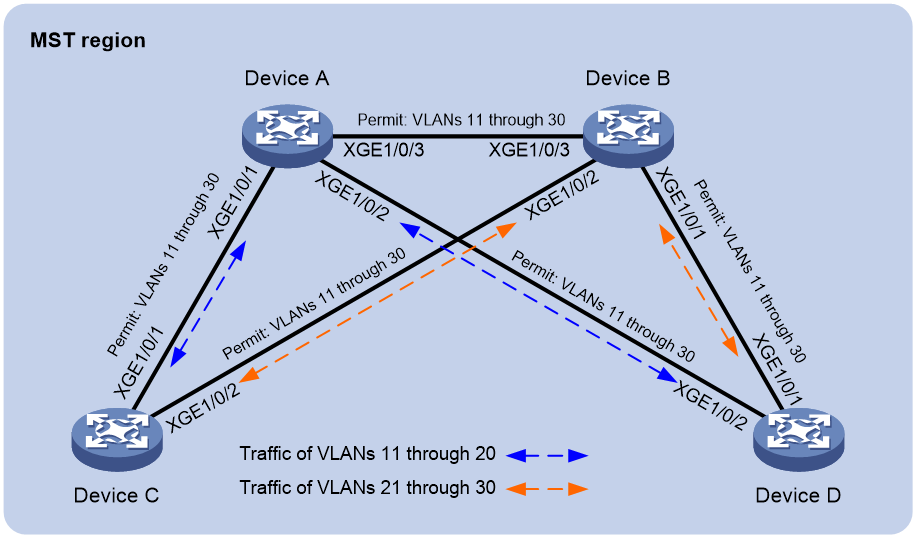
As shown in Figure 1, Device A and Device B operate at the core layer, and Device C and Device D operate at the distribution layer. The ports on the devices have the same path cost, and they all permit VLANs 11 through 30.
Configure MSTP to meet the following requirements:
· Device A, Device B, Device C, and Device D belong to the same MST region.
· MSTIs are used to share the traffic of VLANs 11 through 20 and of VLANs 21 through 30.
Analysis
To assign the devices to the same MST region, make sure the following MST region parameters are the same on the devices:
· Spanning tree mode (the default mode MSTP is used).
· Region name (test in this example).
· Revision level (the default value 0 is used).
· VLAN-to-instance mappings (VLANs 11 through 20 to MIST 1, and VLANs 21 through 30 to MIST 2).
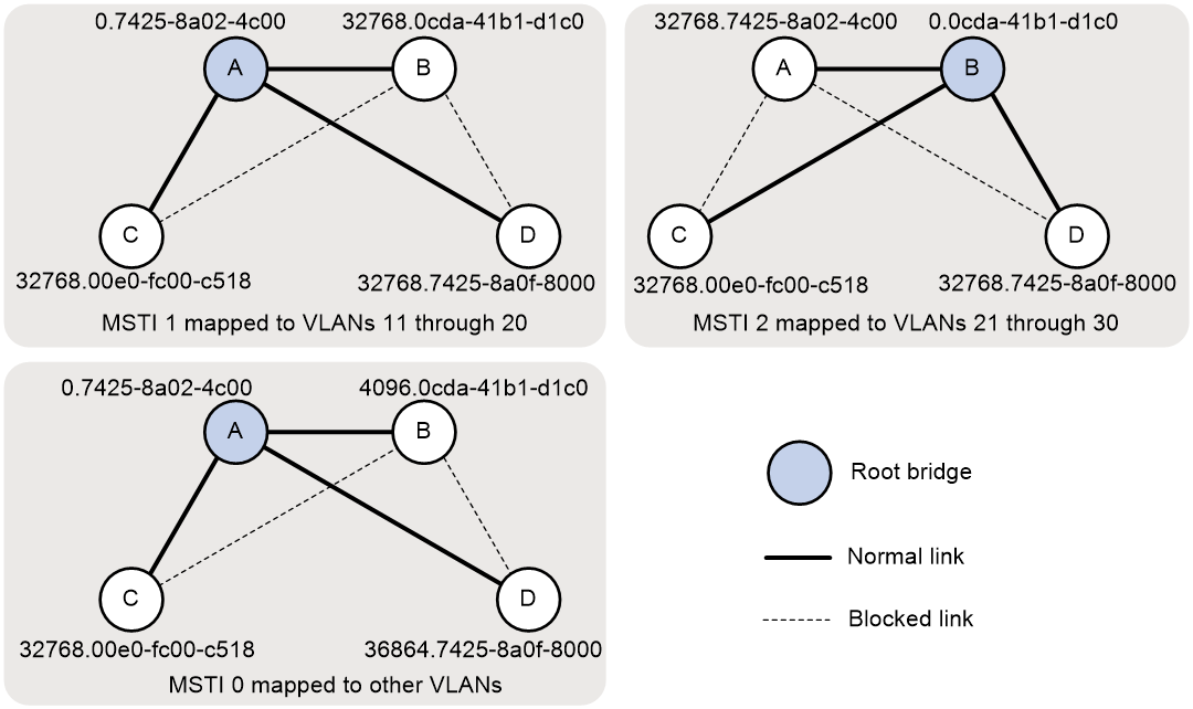
To use redundant links to share the traffic of different VLANs (as shown in Figure 2), perform the following tasks:
· Configure Device A as the root bridge of MSTI 1.
· Configure Device B as the root bridge of MIST 2.
· Assign priorities to Device A, Device B, Device C, and Device D in MSTI 0 in descending order for Device A to be the regional root bridge.
Figure 2 MSTIs mapped to different VLANs
Procedures
Configuring Device A
# Create VLANs 11 through 30.
<DeviceA> system-view
[DeviceA] vlan 11 to 30
# Configure Ten-GigabitEthernet 1/0/1, Ten-GigabitEthernet 1/0/2, and Ten-GigabitEthernet 1/0/3 to trunk VLANs 11 through 30.
[DeviceA] interface range ten-gigabitethernet 1/0/1 to ten-gigabitethernet 1/0/3
[DeviceA-if-range] port link-mode bridge
[DeviceA-if-range] port link-type trunk
[DeviceA-if-range] port trunk permit vlan 11 to 30
[DeviceA-if-range] undo shutdown
[DeviceA-if-range] quit
# Configure the MST region name as test.
[DeviceA] stp region-configuration
[DeviceA-mst-region] region-name test
# Map VLANs 11 through 20 to MSTI 1, and map VLANs 21 through 30 to MSTI 2.
[DeviceA-mst-region] instance 1 vlan 11 to 20
[DeviceA-mst-region] instance 2 vlan 21 to 30
# Activate the MST region configuration.
[DeviceA-mst-region] active region-configuration
[DeviceA-mst-region] quit
# Configure Device A as the root bridge of MSTI 0 and MSTI 1.
[DeviceA] stp instance 0 to 1 root primary
# Enable the spanning tree feature globally.
[DeviceA] stp global enable
Configuring Device B
# Create VLANs 11 through 30.
<DeviceB> system-view
[DeviceB] vlan 11 to 30
# Configure Ten-GigabitEthernet 1/0/1, Ten-GigabitEthernet 1/0/2, and Ten-GigabitEthernet 1/0/3 to trunk VLANs 11 through 30.
[DeviceB] interface range ten-gigabitethernet 1/0/1 to ten-gigabitethernet 1/0/3
[DeviceB-if-range] port link-mode bridge
[DeviceB-if-range] port link-type trunk
[DeviceB-if-range] port trunk permit vlan 11 to 30
[DeviceB-if-range] undo shutdown
[DeviceB-if-range] quit
# Configure the MST region name as test.
[DeviceB] stp region-configuration
[DeviceB-mst-region] region-name test
# Map VLANs 11 through 20 to MSTI 1, and map VLANs 21 through 30 to MSTI 2.
[DeviceB-mst-region] instance 1 vlan 11 to 20
[DeviceB-mst-region] instance 2 vlan 21 to 30
# Activate the MST region configuration.
[DeviceB-mst-region] active region-configuration
[DeviceB-mst-region] quit
# Configure Device B as the root bridge of MSTI 2 and a secondary root bridge of MSTI 0.
[DeviceB] stp instance 2 root primary
[DeviceB] stp instance 0 root secondary
# Enable the spanning tree feature globally.
[DeviceB] stp global enable
Configuring Device C
# Create VLANs 11 through 30.
<DeviceC> system-view
[DeviceC] vlan 11 to 30
# Configure Ten-GigabitEthernet 1/0/1 and Ten-GigabitEthernet 1/0/2 to trunk VLANs 11 through 30.
[DeviceC] interface range ten-gigabitethernet 1/0/1 to ten-gigabitethernet 1/0/2
[DeviceC-if-range] port link-mode bridge
[DeviceC-if-range] port link-type trunk
[DeviceC-if-range] port trunk permit vlan 11 to 30
[DeviceC-if-range] undo shutdown
[DeviceC-if-range] quit
# Configure the MST region name as test.
[DeviceC] stp region-configuration
[DeviceC-mst-region] region-name test
# Map VLANs 11 through 20 through MSTI 1, and map VLANs 21 through 30 to MSTI 2.
[DeviceC-mst-region] instance 1 vlan 11 to 20
[DeviceC-mst-region] instance 2 vlan 21 to 30
# Activate the MST region configuration.
[DeviceC-mst-region] active region-configuration
[DeviceC-mst-region] quit
# Enable the spanning tree feature globally.
[DeviceC] stp global enable
Configuring Device D
# Create VLANs 11 through 30.
<DeviceD> system-view
[DeviceD] vlan 11 to 30
# Configure Ten-GigabitEthernet 1/0/1 and Ten-GigabitEthernet 1/0/2 to trunk VLANs 11 through 30.
[DeviceD] interface range ten-gigabitethernet 1/0/1 to ten-gigabitethernet 1/0/2
[DeviceD-if-range] port link-mode bridge
[DeviceD-if-range] port link-type trunk
[DeviceD-if-range] port trunk permit vlan 11 to 30
[DeviceD-if-range] undo shutdown
[DeviceD-if-range] quit
# Configure the MST region name as test.
[DeviceD] stp region-configuration
[DeviceD-mst-region] region-name test
# Map VLANs 11 through 20 to MSTI 1, and map VLANs 21 through 30 to MSTI 2.
[DeviceD-mst-region] instance 1 vlan 11 to 20
[DeviceD-mst-region] instance 2 vlan 21 to 30
# Activate the MST region configuration.
[DeviceD-mst-region] active region-configuration
[DeviceD-mst-region] quit
# Set the device priority to 36864 in MSTI 0, which is lower than the default priority 32768 of Device C.
[DeviceD] stp instance 0 priority 36864
# Enable the spanning tree feature globally.
[DeviceD] stp global enable
Verifying the configuration
1. Verify that Layer 2 loops have been eliminated in each MSTI:
Use the display stp brief command to display brief spanning tree information on each device.
# Display brief spanning tree information on Device A.
[DeviceA] display stp brief
MST ID Port Role STP State Protection
0 Ten-GigabitEthernet1/0/1 DESI FORWARDING NONE
0 Ten-GigabitEthernet1/0/2 DESI FORWARDING NONE
0 Ten-GigabitEthernet1/0/3 DESI FORWARDING NONE
1 Ten-GigabitEthernet1/0/1 DESI FORWARDING NONE
1 Ten-GigabitEthernet1/0/2 DESI FORWARDING NONE
1 Ten-GigabitEthernet1/0/3 DESI FORWARDING NONE
2 Ten-GigabitEthernet1/0/1 ALTE DISCARDING NONE
2 Ten-GigabitEthernet1/0/2 DESI FORWARDING NONE
2 Ten-GigabitEthernet1/0/3 ROOT FORWARDING NONE
# Display brief spanning tree information on Device B.
[DeviceB] display stp brief
MST ID Port Role STP State Protection
0 Ten-GigabitEthernet1/0/1 DESI FORWARDING NONE
0 Ten-GigabitEthernet1/0/2 DESI FORWARDING NONE
0 Ten-GigabitEthernet1/0/3 ROOT FORWARDING NONE
1 Ten-GigabitEthernet1/0/1 DESI FORWARDING NONE
1 Ten-GigabitEthernet1/0/2 ALTE DISCARDING NONE
1 Ten-GigabitEthernet1/0/3 ROOT FORWARDING NONE
2 Ten-GigabitEthernet1/0/1 DESI FORWARDING NONE
2 Ten-GigabitEthernet1/0/2 DESI FORWARDING NONE
2 Ten-GigabitEthernet1/0/3 DESI FORWARDING NONE
# Display brief spanning tree information on Device C.
[DeviceC] display stp brief
MST ID Port Role STP State Protection
0 Ten-GigabitEthernet1/0/1 ROOT FORWARDING NONE
0 Ten-GigabitEthernet1/0/2 ALTE DISCARDING NONE
1 Ten-GigabitEthernet1/0/1 ROOT FORWARDING NONE
1 Ten-GigabitEthernet1/0/2 DESI FORWARDING NONE
2 Ten-GigabitEthernet1/0/1 DESI FORWARDING NONE
2 Ten-GigabitEthernet1/0/2 ROOT FORWARDING NONE
# Display brief spanning tree information on Device D.
[DeviceD] display stp brief
MST ID Port Role STP State Protection
0 Ten-GigabitEthernet1/0/1 ALTE DISCARDING NONE
0 Ten-GigabitEthernet1/0/2 ROOT FORWARDING NONE
1 Ten-GigabitEthernet1/0/1 ALTE DISCARDING NONE
1 Ten-GigabitEthernet1/0/2 ROOT FORWARDING NONE
2 Ten-GigabitEthernet1/0/1 ROOT FORWARDING NONE
2 Ten-GigabitEthernet1/0/2 ALTE DISCARDING NONE
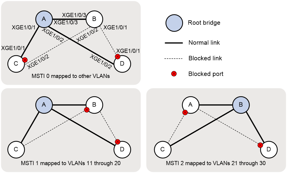
Based on the output, the topology for each MSTI is shown in Figure 3.
2. Verify that the network can accommodate topology changes:
# Shut down Ten-GigabitEthernet 1/0/1 on Device C. (Details not shown.)
# Display brief spanning tree information on all devices.
[DeviceA] display stp brief
MST ID Port Role STP State Protection
0 Ten-GigabitEthernet1/0/2 DESI FORWARDING NONE
0 Ten-GigabitEthernet1/0/3 DESI FORWARDING NONE
1 Ten-GigabitEthernet1/0/2 DESI FORWARDING NONE
1 Ten-GigabitEthernet1/0/3 DESI FORWARDING NONE
2 Ten-GigabitEthernet1/0/2 DESI FORWARDING NONE
2 Ten-GigabitEthernet1/0/3 ROOT FORWARDING NONE
[DeviceB] display stp brief
MST ID Port Role STP State Protection
0 Ten-GigabitEthernet1/0/1 DESI FORWARDING NONE
0 Ten-GigabitEthernet1/0/2 DESI FORWARDING NONE
0 Ten-GigabitEthernet1/0/3 ROOT FORWARDING NONE
1 Ten-GigabitEthernet1/0/1 DESI FORWARDING NONE
1 Ten-GigabitEthernet1/0/2 DESI FORWARDING NONE
1 Ten-GigabitEthernet1/0/3 ROOT FORWARDING NONE
2 Ten-GigabitEthernet1/0/1 DESI FORWARDING NONE
2 Ten-GigabitEthernet1/0/2 DESI FORWARDING NONE
2 Ten-GigabitEthernet1/0/3 DESI FORWARDING NONE
[DeviceC] display stp brief
MST ID Port Role STP State Protection
0 Ten-GigabitEthernet1/0/2 ROOT FORWARDING NONE
1 Ten-GigabitEthernet1/0/2 ROOT FORWARDING NONE
2 Ten-GigabitEthernet1/0/2 ROOT FORWARDING NONE
[DeviceD] display stp brief
MST ID Port Role STP State Protection
0 Ten-GigabitEthernet1/0/1 ALTE DISCARDING NONE
0 Ten-GigabitEthernet1/0/2 ROOT FORWARDING NONE
1 Ten-GigabitEthernet1/0/1 ALTE DISCARDING NONE
1 Ten-GigabitEthernet1/0/2 ROOT FORWARDING NONE
2 Ten-GigabitEthernet1/0/1 ROOT FORWARDING NONE
2 Ten-GigabitEthernet1/0/2 ALTE DISCARDING NONE
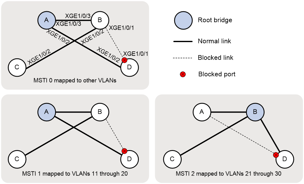
Based on the output, the topology for each MSTI is shown in Figure 4.
Configuration files
· Device A:
#
vlan 1
#
vlan 11 to 30
#
stp region-configuration
region-name test
instance 1 vlan 11 to 20
instance 2 vlan 21 to 30
active region-configuration
#
stp instance 0 to 1 root primary
stp global enable
#
interface Ten-GigabitEthernet1/0/1
port link-mode bridge
port link-type trunk
port trunk permit vlan 1 11 to 30
#
interface Ten-GigabitEthernet1/0/2
port link-mode bridge
port link-type trunk
port trunk permit vlan 1 11 to 30
#
interface Ten-GigabitEthernet1/0/3
port link-mode bridge
port link-type trunk
port trunk permit vlan 1 11 to 30
#
· Device B:
#
vlan 1
#
vlan 11 to 30
#
stp region-configuration
region-name test
instance 1 vlan 11 to 20
instance 2 vlan 21 to 30
active region-configuration
#
stp instance 0 root secondary
stp instance 2 root primary
stp global enable
#
interface Ten-GigabitEthernet1/0/1
port link-mode bridge
port link-type trunk
port trunk permit vlan 1 11 to 30
#
interface Ten-GigabitEthernet1/0/2
port link-mode bridge
port link-type trunk
port trunk permit vlan 1 11 to 30
#
interface Ten-GigabitEthernet1/0/3
port link-mode bridge
port link-type trunk
port trunk permit vlan 1 11 to 30
#
· Device C:
#
vlan 1
#
vlan 11 to 30
#
stp region-configuration
region-name test
instance 1 vlan 11 to 20
instance 2 vlan 21 to 30
active region-configuration
#
stp global enable
#
interface Ten-GigabitEthernet1/0/1
port link-mode bridge
port link-type trunk
port trunk permit vlan 1 11 to 30
#
interface Ten-GigabitEthernet1/0/2
port link-mode bridge
port link-type trunk
port trunk permit vlan 1 11 to 30
#
· Device D:
#
vlan 1
#
vlan 11 to 30
#
stp region-configuration
region-name test
instance 1 vlan 11 to 20
instance 2 vlan 21 to 30
active region-configuration
#
stp instance 0 priority 36864
stp global enable
#
interface Ten-GigabitEthernet1/0/1
port link-mode bridge
port link-type trunk
port trunk permit vlan 1 11 to 30
#
interface Ten-GigabitEthernet1/0/2
port link-mode bridge
port link-type trunk
port trunk permit vlan 1 11 to 30
#
Example: Configuring PVST
Network configuration
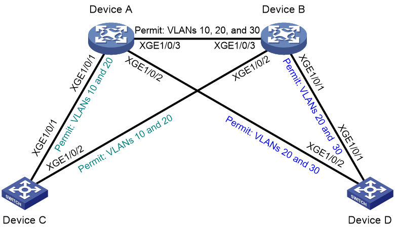
As shown in Figure 5, Device A and Device B operate at the distribution layer, and Device C and Device D operate at the access layer. The ports on the devices have the same path cost.
Configure PVST to meet the following requirements:
· Redundant links are used for load sharing.
· Packets of each VLAN are forwarded along its spanning tree.
Analysis
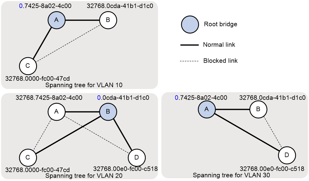
For traffic of different VLANs to be shared along the spanning trees in Figure 6, perform the following tasks:
· Configure Device A as the root bridge of the spanning trees for VLAN 10 and VLAN 30.
· Configure Device B as the root bridge of the spanning tree for VLAN 20.
Figure 6 VLAN spanning tree topologies
Procedures
Configuring Device A
# Create VLAN 10, VLAN 20, and VLAN 30.
<DeviceA> system-view
[DeviceA] vlan 10
[DeviceA-vlan10] vlan 20
[DeviceA-vlan20] vlan 30
[DeviceA-vlan30] quit
# Configure Ten-GigabitEthernet 1/0/1 to trunk VLAN 10 and VLAN 20.
[DeviceA] interface ten-gigabitethernet 1/0/1
[DeviceA-Ten-GigabitEthernet1/0/1] port link-mode bridge
[DeviceA-Ten-GigabitEthernet1/0/1] port link-type trunk
[DeviceA-Ten-GigabitEthernet1/0/1] port trunk permit vlan 10 20
[DeviceA-Ten-GigabitEthernet1/0/1] undo shutdown
[DeviceA-Ten-GigabitEthernet1/0/1] quit
# Configure Ten-GigabitEthernet 1/0/2 to trunk VLAN 20 and VLAN 30.
[DeviceA] interface ten-gigabitethernet 1/0/2
[DeviceA-Ten-GigabitEthernet1/0/2] port link-mode bridge
[DeviceA-Ten-GigabitEthernet1/0/2] port link-type trunk
[DeviceA-Ten-GigabitEthernet1/0/2] port trunk permit vlan 20 30
[DeviceA-Ten-GigabitEthernet1/0/2] undo shutdown
[DeviceA-Ten-GigabitEthernet1/0/2] quit
# Configure Ten-GigabitEthernet 1/0/3 to trunk VLAN 10, VLAN 20, and VLAN 30.
[DeviceA] interface ten-gigabitethernet 1/0/3
[DeviceA-Ten-GigabitEthernet1/0/3] port link-mode bridge
[DeviceA-Ten-GigabitEthernet1/0/3] port link-type trunk
[DeviceA-Ten-GigabitEthernet1/0/3] port trunk permit vlan 10 20 30
[DeviceA-Ten-GigabitEthernet1/0/3] undo shutdown
[DeviceA-Ten-GigabitEthernet1/0/3] quit
# Set the spanning tree mode to PVST.
[DeviceA] stp mode pvst
# Configure Device A as the root bridge of VLAN 10 and VLAN 30.
[DeviceA] stp vlan 10 30 root primary
# Enable the spanning tree feature globally.
[DeviceA] stp global enable
Configuring Device B
# Create VLAN 10, VLAN 20, and VLAN 30.
<DeviceB> system-view
[DeviceB] vlan 10
[DeviceB-vlan10] vlan 20
[DeviceB-vlan20] vlan 30
[DeviceB-vlan30] quit
# Configure Ten-GigabitEthernet 1/0/1 to trunk VLAN 20 and VLAN 30.
[DeviceB] interface ten-gigabitethernet 1/0/1
[DeviceB-Ten-GigabitEthernet1/0/1] port link-mode bridge
[DeviceB-Ten-GigabitEthernet1/0/1] port link-type trunk
[DeviceB-Ten-GigabitEthernet1/0/1] port trunk permit vlan 20 30
[DeviceB-Ten-GigabitEthernet1/0/1] undo shutdown
[DeviceB-Ten-GigabitEthernet1/0/1] quit
# Configure Ten-GigabitEthernet 1/0/2 to trunk VLAN 10 and VLAN 20.
[DeviceB] interface ten-gigabitethernet 1/0/2
[DeviceB-Ten-GigabitEthernet1/0/2] port link-mode bridge
[DeviceB-Ten-GigabitEthernet1/0/2] port link-type trunk
[DeviceB-Ten-GigabitEthernet1/0/2] port trunk permit vlan 10 20
[DeviceB-Ten-GigabitEthernet1/0/2] undo shutdown
[DeviceB-Ten-GigabitEthernet1/0/2] quit
# Configure Ten-GigabitEthernet 1/0/3 to trunk VLAN 10, VLAN 20, and VLAN 30.
[DeviceB] interface ten-gigabitethernet 1/0/3
[DeviceB-Ten-GigabitEthernet1/0/3] port link-mode bridge
[DeviceB-Ten-GigabitEthernet1/0/3] port link-type trunk
[DeviceB-Ten-GigabitEthernet1/0/3] port trunk permit vlan 10 20 30
[DeviceB-Ten-GigabitEthernet1/0/3] undo shutdown
[DeviceB-Ten-GigabitEthernet1/0/3] quit
# Set the spanning tree mode to PVST.
[DeviceB] stp mode pvst
# Configure Device B as the root bridge of VLAN 20.
[DeviceB] stp vlan 20 root primary
# Enable the spanning tree feature globally.
[DeviceB] stp global enable
Configuring Device C
# Create VLAN 10 and VLAN 20.
<DeviceC> system-view
[DeviceC] vlan 10
[DeviceC-vlan10] vlan 20
[DeviceC-vlan20] quit
# Configure Ten-GigabitEthernet 1/0/1 and Ten-GigabitEthernet 1/0/2 to trunk VLAN 10 and VLAN 20.
[DeviceC] interface range ten-gigabitethernet 1/0/1 ten-gigabitethernet 1/0/2
[DeviceC-if-range] port link-mode bridge
[DeviceC-if-range] port link-type trunk
[DeviceC-if-range] port trunk permit vlan 10 20
[DeviceC-if-range] undo shutdown
[DeviceC-if-range] quit
# Set the spanning tree mode to PVST.
[DeviceC] stp mode pvst
# Enable the spanning tree feature globally.
[DeviceC] stp global enable
Configuring Device D
# Create VLAN 20 and VLAN 30.
<DeviceD> system-view
[DeviceD] vlan 20
[DeviceD-vlan20] vlan 30
[DeviceD-vlan30] quit
# Configure Ten-GigabitEthernet 1/0/1 and Ten-GigabitEthernet 1/0/2 to trunk VLAN 20 and VLAN 30.
[DeviceD] interface range ten-gigabitethernet 1/0/1 ten-gigabitethernet 1/0/2
[DeviceD-if-range] port link-mode bridge
[DeviceD-if-range] port link-type trunk
[DeviceD-if-range] port trunk permit vlan 20 30
[DeviceD-if-range] undo shutdown
[DeviceD-if-range] quit
# Set the spanning tree mode to PVST.
[DeviceD] stp mode pvst
# Enable the spanning tree feature globally.
[DeviceD] stp global enable
Verifying the configuration
Use the display stp brief command to display brief spanning tree information on each device.
# Display brief spanning tree information on Device A.
[DeviceA] display stp brief
VLAN ID Port Role STP State Protection
1 Ten-GigabitEthernet1/0/1 ROOT FORWARDING NONE
1 Ten-GigabitEthernet1/0/2 DESI FORWARDING NONE
1 Ten-GigabitEthernet1/0/3 ALTE DISCARDING NONE
10 Ten-GigabitEthernet1/0/1 DESI FORWARDING NONE
10 Ten-GigabitEthernet1/0/3 DESI FORWARDING NONE
20 Ten-GigabitEthernet1/0/1 ALTE DISCARDING NONE
20 Ten-GigabitEthernet1/0/2 ALTE DISCARDING NONE
20 Ten-GigabitEthernet1/0/3 ROOT FORWARDING NONE
30 Ten-GigabitEthernet1/0/2 DESI FORWARDING NONE
30 Ten-GigabitEthernet1/0/3 DESI FORWARDING NONE
# Display brief spanning tree information on Device B.
[DeviceB] display stp brief
VLAN ID Port Role STP State Protection
1 Ten-GigabitEthernet1/0/1 DESI FORWARDING NONE
1 Ten-GigabitEthernet1/0/2 ROOT FORWARDING NONE
1 Ten-GigabitEthernet1/0/3 DESI FORWARDING NONE
10 Ten-GigabitEthernet1/0/2 ALTE DISCARDING NONE
10 Ten-GigabitEthernet1/0/3 ROOT FORWARDING NONE
20 Ten-GigabitEthernet1/0/1 DESI FORWARDING NONE
20 Ten-GigabitEthernet1/0/2 DESI FORWARDING NONE
20 Ten-GigabitEthernet1/0/3 DESI FORWARDING NONE
30 Ten-GigabitEthernet1/0/1 ALTE DISCARDING NONE
30 Ten-GigabitEthernet1/0/3 ROOT FORWARDING NONE
# Display brief spanning tree information on Device C.
[DeviceC] display stp brief
VLAN ID Port Role STP State Protection
1 Ten-GigabitEthernet1/0/1 DESI FORWARDING NONE
1 Ten-GigabitEthernet1/0/2 DESI FORWARDING NONE
10 Ten-GigabitEthernet1/0/1 ROOT FORWARDING NONE
10 Ten-GigabitEthernet1/0/2 DESI FORWARDING NONE
20 Ten-GigabitEthernet1/0/1 DESI FORWARDING NONE
20 Ten-GigabitEthernet1/0/2 ROOT FORWARDING NONE
# Display brief spanning tree information on Device D.
[DeviceD] display stp brief
VLAN ID Port Role STP State Protection
1 Ten-GigabitEthernet1/0/1 ROOT FORWARDING NONE
1 Ten-GigabitEthernet1/0/2 ALTE DISCARDING NONE
20 Ten-GigabitEthernet1/0/1 ROOT FORWARDING NONE
20 Ten-GigabitEthernet1/0/2 DESI FORWARDING NONE
30 Ten-GigabitEthernet1/0/1 DESI FORWARDING NONE
30 Ten-GigabitEthernet1/0/2 ROOT FORWARDING NONE
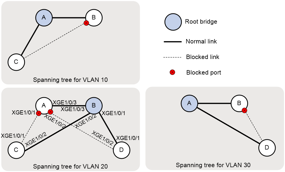
Based on the output, the topology for each VLAN is shown in Figure 7.
Figure 7 VLAN spanning tree topologies
Configuration files
· Device A:
#
vlan 1
#
vlan 10
#
vlan 20
#
vlan 30
#
stp vlan 10 30 root primary
stp mode pvst
stp global enable
#
interface Ten-GigabitEthernet1/0/1
port link-mode bridge
port link-type trunk
port trunk permit vlan 1 10 20
#
interface Ten-GigabitEthernet1/0/2
port link-mode bridge
port link-type trunk
port trunk permit vlan 1 20 30
#
interface Ten-GigabitEthernet1/0/3
port link-mode bridge
port link-type trunk
port trunk permit vlan 1 10 20 30
#
· Device B:
#
vlan 1
#
vlan 10
#
vlan 20
#
vlan 30
#
stp vlan 20 root primary
stp mode pvst
stp global enable
#
interface Ten-GigabitEthernet1/0/1
port link-mode bridge
port link-type trunk
port trunk permit vlan 1 20 30
#
interface Ten-GigabitEthernet1/0/2
port link-mode bridge
port link-type trunk
port trunk permit vlan 1 10 20
#
interface Ten-GigabitEthernet1/0/3
port link-mode bridge
port link-type trunk
port trunk permit vlan 1 10 20 30
#
· Device C:
#
vlan 1
#
vlan 10
#
vlan 20
#
stp mode pvst
stp global enable
#
interface Ten-GigabitEthernet1/0/1
port link-mode bridge
port link-type trunk
port trunk permit vlan 1 10 20
#
interface Ten-GigabitEthernet1/0/2
port link-mode bridge
port link-type trunk
port trunk permit vlan 1 10 20
#
· Device D:
#
vlan 1
#
vlan 20
#
vlan 30
#
stp mode pvst
stp global enable
#
interface Ten-GigabitEthernet1/0/1
port link-mode bridge
port link-type trunk
port trunk permit vlan 1 20 30
#
interface Ten-GigabitEthernet1/0/2
port link-mode bridge
port link-type trunk
port trunk permit vlan 1 20 30
#
Example: Configuring RSTP
Network configuration
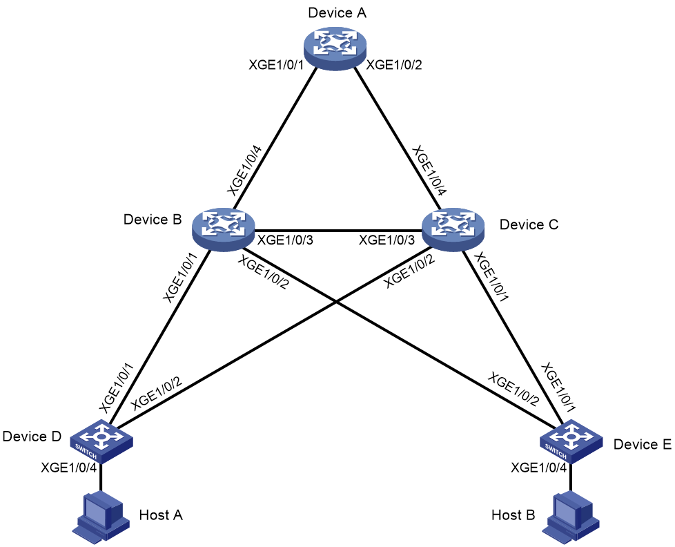
As shown in Figure 8, Device A operates at the core layer, Device B and Device C operate at the distribution layer, and Device D and Device E operate at the access layer. The ports on the devices have the same path cost.
Configure RSTP as follows:
· Configure Device A as the root bridge, and enable root guard to retain its root bridge role when configuration errors or malicious attacks occur.
· Configure Device C as a backup of Device B. When Device B fails, traffic is forwarded through Device C.
· Configure Ten-GigabitEthernet 1/0/4 on Device D and Ten-GigabitEthernet 1/0/4 on Device E as edge ports, and enable BPDU guard on the ports.
Analysis
For Device C to be a backup of Device B, make sure Device C's priority is lower than Device B's priority. In this example, configure the priorities of Device B and Device C as 4096 and 8192.
For Device A to be the root bridge, make sure Device A has the lowest bridge ID (containing the device's priority and MAC address) in the network. In this example, because Device A already has the lowest MAC address, configure the priority as 4096 for Device A to hold the lowest bridge ID.
|
|
NOTE: To configure a device as the root bridge, you also can use the stp root primary or stp priority 0 command to set the device's priority to 0. |
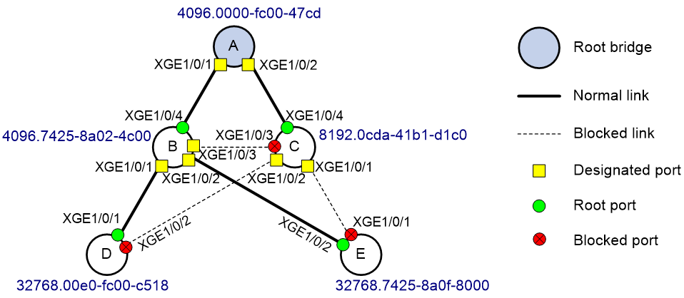
To retain Device A's root bridge role, enable root guard on the designated ports of Device A, Device B, and Device C. To identify the designated ports, use either of the following methods:
· Use the display stp brief command to display the brief spanning tree information. The role is DESI for a designated port.
· Identify the designated ports in the RSTP topology that is calculated based on the device configuration, as shown in Figure 9.
Procedures
Configuring Device A
# Set the spanning tree mode to RSTP.
<DeviceA> system-view
[DeviceA] stp mode rstp
# Configure the priority as 4096 for Device A.
[DeviceA] stp priority 4096
# Enable the spanning tree feature globally.
[DeviceA] stp global enable
# Enable root guard on designated ports Ten-GigabitEthernet 1/0/1 and Ten-GigabitEthernet 1/0/2.
[DeviceA] interface range ten-gigabitethernet 1/0/1 ten-gigabitethernet 1/0/2
[DeviceA-if-range] port link-mode bridge
[DeviceA-if-range] stp root-protection
[DeviceA-if-range] undo shutdown
[DeviceA-if-range] quit
Configuring Device B
# Set the spanning tree mode to RSTP.
<DeviceB> system-view
[DeviceB] stp mode rstp
# Configure the priority as 4096 for Device B.
[DeviceB] stp priority 4096
# Enable the spanning tree feature globally.
[DeviceB] stp global enable
# Enable root guard on designated ports Ten-GigabitEthernet 1/0/1, Ten-GigabitEthernet 1/0/2, and Ten-GigabitEthernet 1/0/3.
[DeviceB] interface range ten-gigabitethernet 1/0/1 to ten-gigabitethernet 1/0/3
[DeviceB-if-range] port link-mode bridge
[DeviceB-if-range] stp root-protection
[DeviceB-if-range] undo shutdown
[DeviceB-if-range] quit
# Bring up Ten-GigabitEthernet 1/0/4.
[DeviceB] interface ten-gigabitethernet 1/0/4
[DeviceB-Ten-GigabitEthernet1/0/4] port link-mode bridge
[DeviceB-Ten-GigabitEthernet1/0/4] undo shutdown
[DeviceB-Ten-GigabitEthernet1/0/4] quit
Configuring Device C
# Set the spanning tree mode to RSTP.
<DeviceC> system-view
[DeviceC] stp mode rstp
# Configure the priority as 8192 for Device C.
[DeviceC] stp priority 8192
# Enable the spanning tree feature globally.
[DeviceC] stp global enable
# Enable root guard on designated ports Ten-GigabitEthernet 1/0/1 and Ten-GigabitEthernet 1/0/2.
[DeviceC] interface range ten-gigabitethernet 1/0/1 to ten-gigabitethernet 1/0/2
[DeviceC-if-range] port link-mode bridge
[DeviceC-if-range] stp root-protection
[DeviceC-if-range] undo shutdown
[DeviceC-if-range] quit
# Bring up Ten-GigabitEthernet 1/0/3 and Ten-GigabitEthernet 1/0/4.
[DeviceC] interface range ten-gigabitethernet 1/0/3 to ten-gigabitethernet 1/0/4
[DeviceC-if-range] port link-mode bridge
[DeviceC-if-range] undo shutdown
[DeviceC-if-range] quit
Configuring Device D
# Set the spanning tree mode to RSTP.
<DeviceD> system-view
[DeviceD] stp mode rstp
# Enable the spanning tree feature globally.
[DeviceD] stp global enable
# Configure Ten-GigabitEthernet 1/0/4 as an edge port, and enable BPDU guard.
[DeviceD] interface ten-gigabitethernet 1/0/4
[DeviceD-Ten-GigabitEthernet1/0/4] port link-mode bridge
[DeviceD-Ten-GigabitEthernet1/0/4] stp edged-port
[DeviceD-Ten-GigabitEthernet1/0/4] undo shutdown
[DeviceD-Ten-GigabitEthernet1/0/4] quit
[DeviceD] stp bpdu-protection
# Bring up Ten-GigabitEthernet 1/0/1 and Ten-GigabitEthernet 1/0/2.
[DeviceD] interface range ten-gigabitethernet 1/0/1 to ten-gigabitethernet 1/0/2
[DeviceD-if-range] port link-mode bridge
[DeviceD-if-range] undo shutdown
[DeviceD-if-range] quit
Configuring Device E
# Configure Device E in the same way Device D is configured. (Details not shown.)
Verifying the configuration
1. Verify that Layer 2 loops have been eliminated in the network:
Use the display stp brief command to display brief spanning tree information on each device.
# Display the brief spanning tree information on Device A.
[DeviceA] display stp brief
MST ID Port Role STP State Protection
0 Ten-GigabitEthernet1/0/1 DESI FORWARDING NONE
0 Ten-GigabitEthernet1/0/2 DESI FORWARDING NONE
# Display the brief spanning tree information on Device B.
[DeviceB] display stp brief
MST ID Port Role STP State Protection
0 Ten-GigabitEthernet1/0/1 DESI FORWARDING NONE
0 Ten-GigabitEthernet1/0/2 DESI FORWARDING NONE
0 Ten-GigabitEthernet1/0/3 DESI FORWARDING NONE
0 Ten-GigabitEthernet1/0/4 ROOT FORWARDING NONE
# Display the brief spanning tree information on Device C.
[DeviceC] display stp brief
MST ID Port Role STP State Protection
0 Ten-GigabitEthernet1/0/1 DESI FORWARDING NONE
0 Ten-GigabitEthernet1/0/2 DESI FORWARDING NONE
0 Ten-GigabitEthernet1/0/3 ALTE DISCARDING NONE
0 Ten-GigabitEthernet1/0/4 ROOT FORWARDING NONE
# Display the brief spanning tree information on Device D.
[DeviceD] display stp brief
MST ID Port Role STP State Protection
0 Ten-GigabitEthernet1/0/1 ROOT FORWARDING NONE
0 Ten-GigabitEthernet1/0/2 ALTE DISCARDING NONE
0 Ten-GigabitEthernet1/0/4 DESI FORWARDING BPDU
# Display the brief spanning tree information on Device E.
[DeviceE] display stp brief
MST ID Port Role STP State Protection
0 Ten-GigabitEthernet1/0/1 ALTE DISCARDING NONE
0 Ten-GigabitEthernet1/0/2 ROOT FORWARDING NONE
0 Ten-GigabitEthernet1/0/4 DESI FORWARDING BPDU
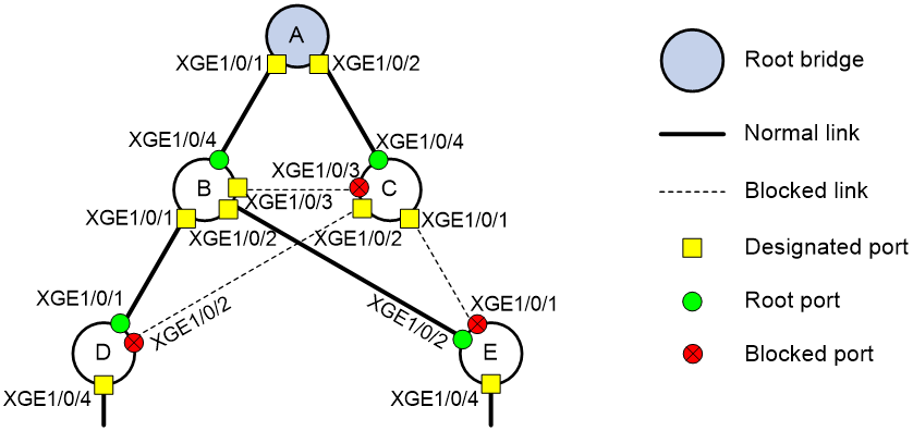
Based on the output, the topology for the network is shown in Figure 10.
2. Verify that root guard can retain Device A's root bridge role:
# Verify that Device A is the root bridge in the network.
[DeviceD] display stp
-------[CIST Global Info] [Mode RSTP] -------
Bridge ID : 32768.00e0-fc00-c518
Bridge times : Hello 2s MaxAge 20s FwdDelay 15s MaxHops 20
Root ID/ERPC : 4096.0000-fc00-47cd, 40
RegRoot ID/IRPC : 32768.00e0-fc00-c518, 0
...
# Set the priority to 0 for Device D. Because the priority is higher than the priority of Device A, Device D considers itself as the root bridge and sends BPDUs that contain its bridge ID 0.00e0-fc00-c518.
[DeviceD] stp priority 0
[DeviceD] display stp
-------[CIST Global Info] [Mode RSTP] -------
Bridge ID : 0.00e0-fc00-c518
Bridge times : Hello 2s MaxAge 20s FwdDelay 15s MaxHops 20
Root ID/ERPC : 0.00e0-fc00-c518, 0
RegRoot ID/IRPC : 0.00e0-fc00-c518, 0
...
# Set the priority to 0 for Device E. Because the priority is higher than the priority of Device A. Device E considers itself as the root bridge and sends BPDUs that contain its bridge ID 0.7425-8a0f-8000.
[DeviceE] stp priority 0
[DeviceE] display stp
-------[CIST Global Info] [Mode RSTP] -------
Bridge ID : 0.7425-8a0f-8000
Bridge times : Hello 2s MaxAge 20s FwdDelay 15s MaxHops 20
Root ID/ERPC : 0.7425-8a0f-8000, 0
RegRoot ID/IRPC : 0.7425-8a0f-8000, 0
...
# Verify that Device A is still the root bridge in the network.
[DeviceB] display stp
-------[CIST Global Info] [Mode RSTP] -------
Bridge ID : 4096.7425-8a02-4c00
Bridge times : Hello 2s MaxAge 20s FwdDelay 15s MaxHops 20
Root ID/ERPC : 4096.0000-fc00-47cd, 20
RegRoot ID/IRPC : 4096.7425-8a02-4c00, 0
...
[DeviceC] display stp
-------[CIST Global Info] [Mode RSTP] -------
Bridge ID : 8192.0cda-41b1-d1c0
Bridge times : Hello 2s MaxAge 20s FwdDelay 15s MaxHops 20
Root ID/ERPC : 4096.0000-fc00-47cd, 20
RegRoot ID/IRPC : 8192.0cda-41b1-d1c0, 0
...
# Verify that Device A cannot retain its root bridge role when root guard is disabled on a designated port on Device B (for example, Ten-GigabitEthernet 1/0/2).
[DeviceB] interface ten-gigabitethernet 1/0/2
[DeviceB-Ten-GigabitEthernet1/0/2] undo stp root-protection
[DeviceB-Ten-GigabitEthernet1/0/2] display stp
-------[CIST Global Info] [Mode RSTP] -------
Bridge ID : 4096.7425-8a02-4c00
Bridge times : Hello 2s MaxAge 20s FwdDelay 15s MaxHops 20
Root ID/ERPC : 0.7425-8a0f-8000, 20
...
[DeviceB-Ten-GigabitEthernet1/0/2] display stp brief
MST ID Port Role STP State Protection
0 Ten-GigabitEthernet1/0/1 DESI DISCARDING ROOT
0 Ten-GigabitEthernet1/0/2 ROOT FORWARDING NONE
0 Ten-GigabitEthernet1/0/3 DESI FORWARDING NONE
0 Ten-GigabitEthernet1/0/4 DESI FORWARDING NONE
3. Verify that traffic is forwarded through Device C when Device B fails:
# Reboot Device B. (Details not shown.)
# Display the brief spanning tree information on Device A, Device C, Device D, and Device E before Device B completes the reboot.
[DeviceA] dis stp brief
MST ID Port Role STP State Protection
0 Ten-GigabitEthernet1/0/2 DESI FORWARDING ROOT
[DeviceC] dis stp brief
MST ID Port Role STP State Protection
0 Ten-GigabitEthernet1/0/1 DESI FORWARDING ROOT
0 Ten-GigabitEthernet1/0/2 DESI FORWARDING ROOT
0 Ten-GigabitEthernet1/0/4 ROOT FORWARDING NONE
[DeviceD] dis stp brief
MST ID Port Role STP State Protection
0 Ten-GigabitEthernet1/0/2 ROOT FORWARDING NONE
0 Ten-GigabitEthernet1/0/4 DESI FORWARDING BPDU
[DeviceE] dis stp brief
MST ID Port Role STP State Protection
0 Ten-GigabitEthernet1/0/1 ROOT FORWARDING NONE
0 Ten-GigabitEthernet1/0/4 DESI FORWARDING BPDU
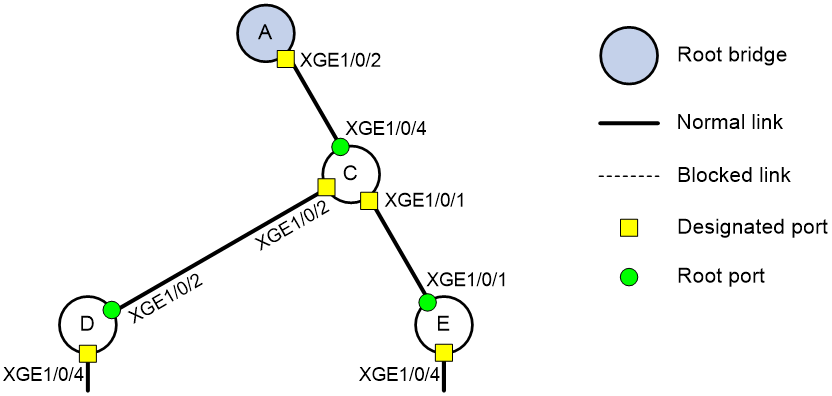
Based on the network topology, the topology for the network is shown in Figure 11.
4. Verify that BPDU guard can protect edge ports from attacks:
# Verify that the edge port Ten-GigabitEthernet 1/0/4 on Device D goes down when the port receives configuration BPDUs.
[DeviceD] display stp down-port
Down Port Reason
Ten-GigabitEthernet1/0/4 BPDU-Protected
# Verify that Ten-GigabitEthernet 1/0/4 goes up when it does not receive any configuration BPDUs from the peer end.
[DeviceD] display interface brief | include UP
InLoop0 UP UP(s) --
M-E0/0/0 UP UP 192.168.2.125
NULL0 UP UP(s) --
XGE1/0/1 UP 1G(a) F(a) T 1
XGE1/0/2 UP 1G(a) F(a) T 1
XGE1/0/4 UP 1G(a) F(a) A 1
Configuration files
· Device A:
#
vlan 1
#
stp instance 0 priority 4096
stp mode rstp
stp global enable
#
interface Ten-GigabitEthernet1/0/1
port link-mode bridge
stp root-protection
#
interface Ten-GigabitEthernet1/0/2
port link-mode bridge
stp root-protection
#
· Device B:
#
vlan 1
#
stp instance 0 priority 4096
stp mode rstp
stp global enable
#
interface Ten-GigabitEthernet1/0/1
port link-mode bridge
stp root-protection
#
interface Ten-GigabitEthernet1/0/2
port link-mode bridge
stp root-protection
#
interface Ten-GigabitEthernet1/0/3
port link-mode bridge
stp root-protection
#
interface Ten-GigabitEthernet1/0/4
port link-mode bridge
#
· Device C:
#
vlan 1
#
stp instance 0 priority 8192
stp mode rstp
stp global enable
#
interface Ten-GigabitEthernet1/0/1
port link-mode bridge
stp root-protection
#
interface Ten-GigabitEthernet1/0/2
port link-mode bridge
stp root-protection
#
interface Ten-GigabitEthernet1/0/3
port link-mode bridge
#
interface Ten-GigabitEthernet1/0/4
port link-mode bridge
#
· Device D:
#
vlan 1
#
stp mode rstp
stp bpdu-protection
stp global enable
#
interface Ten-GigabitEthernet1/0/1
port link-mode bridge
#
interface Ten-GigabitEthernet1/0/2
port link-mode bridge
#
interface Ten-GigabitEthernet1/0/4
port link-mode bridge
stp edged-port
#
· Device E:
#
vlan 1
#
stp mode rstp
stp bpdu-protection
stp global enable
#
interface Ten-GigabitEthernet1/0/1
port link-mode bridge
#
interface Ten-GigabitEthernet1/0/2
port link-mode bridge
#
interface Ten-GigabitEthernet1/0/4
port link-mode bridge
stp edged-port
#
Related documentation
· H3C S7500X Switch Series Layer 2—LAN Switching Configuration Guide-R758X
· H3C S7500X Switch Series Layer 2—LAN Switching Command Reference-R758X