| Title | Size | Downloads |
|---|---|---|
| 16-EPON Configuration Examples-H3C_EPON_Configuration_Examples.pdf | 98.72 KB |
- Table of Contents
- Related Documents
-
| Title | Size | Download |
|---|---|---|
| 01-H3C_EPON_Configuration_Examples | 98.72 KB |
|
|
|
H3C EPON Configuration Examples |
|
|
|
|
|
|
Software version: Release 7585P05
Document version: 6W100-20200330
Copyright © 2020 New H3C Technologies Co., Ltd. All rights reserved.
No part of this manual may be reproduced or transmitted in any form or by any means without prior written consent of New H3C Technologies Co., Ltd.
Except for the trademarks of New H3C Technologies Co., Ltd., any trademarks that may be mentioned in this document are the property of their respective owners.
The information in this document is subject to change without notice.
Contents
Example: Configuring the EPON video monitoring service (VLAN tag mode)
Example: Configuring an EPON campus wireless network (VLAN trunk mode)
Introduction
This document provides examples of configuring Ethernet Passive Optical Network (EPON).
EPON combines the benefits of Ethernet and PON, and is applicable to remote broadband IP services.
Prerequisites
The configuration examples in this document were created and verified in a lab environment, and all the devices were started with the factory default configuration. When you are working on a live network, make sure you understand the potential impact of every command on your network.
This document assumes that you have basic knowledge of EPON.
Example: Configuring the EPON video monitoring service (VLAN tag mode)
Network configuration
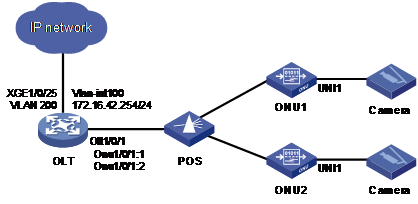
As shown in Figure 1, a community uses ONUs to connect video monitoring cameras. Configure EPON to meet the following requirements:
· Use the OLT to remotely manage the ONUs.
· The data from cameras is managed in a separate VLAN in the EPON network, and can be transmitted to an external IP network.
· To guarantee video quality, expand the maximum uplink bandwidth to 1 Gbps and perform flow control on the video traffic.
Analysis
To meet the requirements, perform the following tasks on the OLT:
· Bind ONUs to the OLT, and then remotely manage ONUs through ONU interfaces. This section uses ONU 1/0/1:1 to manage ONU1 as an example.
· Use VLAN 100 as the management VLAN of ONUs.
¡ Configure the downlink packets from the OLT interface and its ONU interfaces to carry VLAN tag 100.
¡ To Telnet to ONUs, create VLAN interface 100 on the OLT for the management VLAN of ONUs.
· Use VLAN 200 as the video service VLAN.
¡ To tag the data packets from cameras with VLAN tag 200, configure the VLAN tag mode on the UNIs connecting to cameras.
¡ To transmit the video packets in VLAN 200 to an external network, assign the uplink interface XGE 1/0/25 to VLAN 200.
Procedures
1. Bind ONUs to the OLT.
# Set the device name for the OLT.
<Sysname> system-view
[Sysname] sysname OLT
# Bind the two ONUs to ONU interfaces on the OLT. This example uses automatic binding. ONU interfaces ONU 1/0/1:1 and ONU 1/0/1:2 will be automatically created and bound to ONUs separately.
[OLT] ftth
[OLT-ftth] onu bind auto slot 1
[OLT-ftth] quit
2. Configure the management VLAN for ONUs.
# Create VLAN 100 on the OLT. Create VLAN-interface 100, and assign IP address 172.16.42.254 to the VLAN interface. The IP address will be used as the gateway IP address of ONUs.
[OLT] vlan 100
[OLT-vlan100] quit
[OLT] interface vlan-interface 100
[OLT-Vlan-interface100] ip address 172.16.42.254 24
[OLT-Vlan-interface100] quit
# Configure OLT 1/0/1 as a hybrid port, and assign it to VLAN 100 as a tagged member.
[OLT] interface olt1/0/1
[OLT-Olt1/0/1] port link-type hybrid
[OLT-Olt1/0/1] port hybrid vlan 100 tagged
[OLT-Olt1/0/1] quit
# Configure ONU 1/0/1:1 as a trunk port and assign it to all VLANs.
[OLT] interface onu1/0/1:1
[OLT-Onu1/0/1:1] port link-type trunk
[OLT-Onu1/0/1:1] port trunk permit vlan all
# Configure VLAN 100 as the management VLAN for ONU1 bound to ONU 1/0/1:1. Bring up management VLAN interface 100, assign IP address 172.16.42.24 to it, and specify the gateway address as the IP address of VLAN 100 on the OLT.
[OLT-Onu1/0/1:1] management-vlan 100
[OLT-Onu1/0/1:1] undo shutdown management-vlan-interface
[OLT-Onu1/0/1:1] ip address 172.16.42.24 24 gateway 172.16.42.254
[OLT-Onu1/0/1:1] quit
3. Configure the video service VLAN:
# Create VLAN 200, which is to be used as the video service VLAN. Set the VLAN operation mode to tag mode on UNI 1 on ONU1. Then, packets received on UNI 1 will be tagged with VLAN 200.
[OLT] vlan 200
[OLT-vlan200] quit
[OLT] interface onu1/0/1:1
[OLT-Onu1/0/1:1] uni 1 vlan-mode tag pvid 200
[OLT-Onu1/0/1:1] quit
# Assign the interfaces that video packets pass through (including ONU 1/0/1:1, OLT 1/0/1, and uplink interface XGE 1/0/25 connecting to the external network) to VLAN 200. ONU 1/0/1:1 has been assigned to all VLANs, so you do not need to assign it to VLAN 200 again.
[OLT] interface olt1/0/1
[OLT-Olt1/0/1] port hybrid vlan 200 tagged
[OLT-Olt1/0/1] quit
[OLT] interface ten-gigabitethernet 1/0/25
[OLT-Ten-GigabitEthernet1/0/25] port link-type hybrid
[OLT-Ten-GigabitEthernet1/0/25] port hybrid vlan 200 tagged
[OLT-Ten-GigabitEthernet1/0/25] quit
4. Configure the maximum uplink bandwidth and flow control
# Set the maximum uplink bandwidth to 1000000 kbps on ONU 1. Because the maximum-bandwidth argument is measured in 64 kbps, set the maximum-bandwidth argument to 1000000/64=15625.
[OLT] interface onu1/0/1:1
[OLT-Onu1/0/1:1] upstream-sla maximum-bandwidth 15625
The maximum-bandwidth of upstream is 1000000 kbps
# Enable flow control on UNI 1 to avoid packet loss caused by congestion.
[OLT-Onu1/0/1:1] uni 1 flow-control
|
|
NOTE: You also need to enable flow control on the peer of the UNI, the camera connecting to the UNI. |
Verifying the configuration
1. Display information about VLAN 200 on the OLT.
<OLT> display vlan 200
VLAN ID: 200
VLAN type: Static
Route interface: Not configured
Description: VLAN 0200
Name: VLAN 0200
Tagged ports:
Olt1/0/1
Onu1/0/1:1
Ten-GigabitEthernet1/0/25
Untagged ports: None
The output shows that the interfaces that video packets pass through are assigned to VLAN 200.
When untagged packets are received on UNI 1 of ONU1, packets carrying VLAN tag 200 can be received on XGE 1/0/25 of the OLT.
2. Verify that you can Telnet to the ONU through the IP address of the ONU's management VLAN interface 100.
<OLT> telnet 172.16.42.24
Trying 172.16.42.24 ...
Press CTRL+K to abort
Connected to 172.16.42.24 ...
Login: admin
Password:
...
Copyright (c) 2004-2019 New H3C Technologies Co., Ltd. All rights reserved.
H3C ET354 uptime is 01:13:40 11 days
Hardware version : A
Vendor ID : H3C
Onu Model : 3540
Build time : 2019-04-24 13:48:28
Internal version : V100R001B01D016SP01
Configuration files
sysname OLT
#
vlan 100
#
vlan 200
#
ftth
onu bind auto slot 1
#
interface Vlan-interface100
ip address 172.16.42.254 255.255.255.0
#
interface Ten-GigabitEthernet1/0/25
port link-type hybrid
port hybrid vlan 200 tagged
port hybrid vlan 1 untagged
#
interface Olt1/0/1
using onu 1
port link-type hybrid
port hybrid vlan 100 200 tagged
port hybrid vlan 1 untagged
#
interface Onu1/0/1:1
bind onu-id 9428-2ec3-61b6
management-vlan 100
undo shutdown management-vlan-interface
upstream-sla maximum-bandwidth 15625
ip address 172.16.42.24 255.255.255.0 gateway 172.16.42.254
uni 1 flow-control
uni 1 vlan-mode tag pvid 200
port link-type trunk
port trunk permit vlan all
#
Example: Configuring an EPON campus wireless network (VLAN trunk mode)
Network configuration
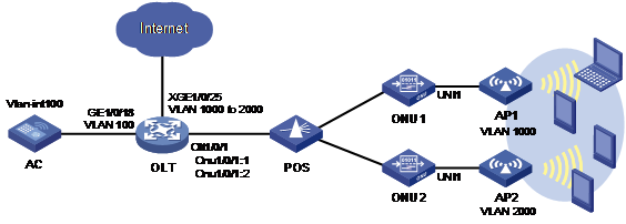
As shown in Figure 2, a campus has multiple APs deployed to provide wireless network access services. Configure EPON to meet the following requirements:
· Use an AC to manage the attached APs through an EPON network.
· Each AP can use VLANs 1000 through 2000 to isolate the network accessing traffic. Packets from these VLANs can be forwarded to Internet through the EPON network.
Analysis
To meet the requirements, perform the following tasks on the OLT:
· Bind ONUs to the OLT.
· Configure VLAN 100 as the management VLAN. Assign the interfaces along the management packet transmission path (AC-> OLT-> ONU-> AP) to VLAN 100.
· Configure VLANs 1000 through 2000 as the network access service VLANs.
¡ Because APs have added VLAN tags to packets, you only need to set the VLAN operation mode to trunk mode on ONU UNIs connecting to APs and allow packets from these VLANs to pass through. This section uses ONU 1/0/1:1 to manage ONU1 as an example.
¡ To transmit the packets from these VLANs to Internet, assign the uplink interface XGE 1/0/25 to VLANs 1000 through 2000.
Procedures
1. Bind ONUs to the OLT.
# Set the device name for the OLT.
<Sysname> system-view
[Sysname] sysname OLT
# Bind the two ONUs to ONU interfaces on the OLT. This example uses automatic binding.
[OLT] ftth
[OLT-ftth] onu bind auto slot 1
[OLT-ftth] quit
2. Configure the management VLAN.
# Create VLAN 100 on the OLT. The VLAN is to be used as the management VLAN.
[OLT] vlan 100
[OLT-vlan100] quit
# Configure GE 1/0/18 (interface connecting to the AC) and OLT 1/0/1 (interface connecting to ONUs) as hybrid ports and assign them to VLAN 100 as tagged members.
[OLT] interface gigabitethernet 1/0/18
[OLT-GigabitEthernet1/0/18] port link-type hybrid
[OLT-GigabitEthernet1/0/18] port hybrid vlan 100 tagged
[OLT-GigabitEthernet1/0/18] quit
[OLT] interface olt1/0/1
[OLT-Olt1/0/1] port link-type hybrid
[OLT-Olt1/0/1] port hybrid vlan 100 tagged
[OLT-Olt1/0/1] quit
# Configure ONU 1/0/1:1 as a trunk port and assign it to all VLANs.
[OLT] interface onu1/0/1:1
[OLT-Onu1/0/1:1] port link-type trunk
[OLT-Onu1/0/1:1] port trunk permit vlan all
[OLT-Onu1/0/1:1] quit
3. Configure the network access service VLANs:
# Create network access service VLANs 1000 through 2000.
[OLT] vlan 1000 to 2000
[OLT-vlan200] quit
# Set the VLAN operation mode to trunk on UNI 1 of ONU1. Specify the PVID as 100, so that the untagged management packets from APs will be tagged with VLAN 100. Permit packets from network access service VLANs 1000 through 2000 to pass through.
[OLT] interface onu1/0/1:1
[OLT-Onu1/0/1:1] uni 1 vlan-mode trunk pvid 100 1000 to 2000
[OLT-Onu1/0/1:1] quit
# Assign the interfaces that network accessing packets pass through (including ONU 1/0/1:1, OLT 1/0/1, and uplink interface XGE 1/0/25 connecting to the external network) to VLANs 1000 through 2000. ONU 1/0/1:1 has been assigned to all VLANs, so you do not need to assign it to VLAN 200 again.
[OLT] interface olt1/0/1
[OLT-Olt1/0/1] port hybrid vlan 1000 to 2000 tagged
[OLT-Olt1/0/1] quit
[OLT] interface ten-gigabitethernet 1/0/25
[OLT-Ten-GigabitEthernet1/0/25] port link-type hybrid
[OLT-Ten-GigabitEthernet1/0/25] port hybrid vlan 1000 to 2000 tagged
[OLT-Ten-GigabitEthernet1/0/25] quit
Verifying the configuration
1. When the AC and an AP are on the same network segment, they can ping each other, and the AP can register with the AC.
2. When an AP sends packets from VLANs 1000 through 2000 to the ONU, uplink interface XGE 1/0/25 on the OLT can receive these packets.
Configuration profiles
#
sysname OLT
#
vlan 100
#
vlan 1000 to 2000
#
ftth
onu bind auto slot 1
#
interface GigabitEthernet1/0/18
port link-type hybrid
port hybrid vlan 100 tagged
port hybrid vlan 1 untagged
combo enable copper
#
interface Ten-GigabitEthernet1/0/25
port link-type hybrid
port hybrid vlan 1000 to 2000 tagged
port hybrid vlan 1 untagged
#
interface Olt1/0/1
using onu 1
port link-type hybrid
port hybrid vlan 100 1000 to 2000 tagged
port hybrid vlan 1 untagged
#
interface Onu1/0/1:1
bind onu-id 9428-2ec3-61b6
uni 1 vlan-mode trunk pvid 100 1000 to 2000
port link-type trunk
port trunk permit vlan all
#
Related documentation
· H3C S7500E Switch Series EPON Configuration Guide-R758X
· H3C S7500E Switch Series EPON Command Reference-R758X
