- Table of Contents
- Related Documents
-
| Title | Size | Download |
|---|---|---|
| 01-H3C_EVI_Configuration_Examples | 329.49 KB |
|
|
|
H3C EVI Configuration Examples |
|
|
|
|
|
|
Software version: Release 7585P05
Document version: 6W100-20200330
Copyright © 2020 New H3C Technologies Co., Ltd. All rights reserved.
No part of this manual may be reproduced or transmitted in any form or by any means without prior written consent of New H3C Technologies Co., Ltd.
Except for the trademarks of New H3C Technologies Co., Ltd., any trademarks that may be mentioned in this document are the property of their respective owners.
The information in this document is subject to change without notice.
Contents
General restrictions and guidelines
Example: Configuring EVI with MDC
Example: Configuring EVI with IRF
Introduction
This document provides examples for using EVI with MDC and IRF.
Ethernet Virtual Interconnect (EVI) is a MAC-in-IP technology that provides Layer 2 connectivity between distant Layer 2 network sites across an IP routed network. It is used for connecting geographically dispersed sites of a virtualized large-scale data center that requires Layer 2 adjacency.
EVI enables long-distance virtual machine workload mobility and data mobility, disaster recovery, and business continuity. For example, virtual machines can move between data center sites without changing their IP addresses, so their movements are transparent to users and do not disrupt traffic.
Prerequisites
The configuration examples in this document were created and verified in a lab environment, and all the devices were started with the factory default configuration. When you are working on a live network, make sure you understand the potential impact of every command on your network.
This document assumes that you have basic knowledge of EVI, MDC, and IRF.
General restrictions and guidelines
When you configure EVI, follow these restrictions and guidelines:
· For an extended VLAN at a site, you must place the VLAN's gateway on the edge device at the local site rather than a remote site.
· You must install licenses for EVI and MDC. Licenses include DATACENTER licenses and CAMPUS licenses. A DATACENTER license covers both EVI and MDC. A CAMPUS license covers only MDC.
Example: Configuring EVI with MDC
Network configuration
As shown in Figure 1:
· Set up an EVI network to extend VLAN 1000 across two data center sites in different cities over an IP transport network. The gateways and IP addresses of servers or virtual machines in VLAN 1000 must not change after they are moved from one site to another.
· Use MDCs on edge devices to separate EVI tunneling services from gateway services.
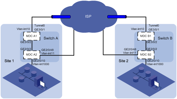
Table 1 IP address assignment
|
Device |
Interface |
IP address |
Device |
Interface |
IP address |
|
MDC A1 |
Loopback 0 |
1.1.1.1/32 |
MDC B1 |
Loopback 0 |
2.2.2.2/32 |
|
|
VLAN-interface 10 |
10.1.1.1/24 |
|
VLAN-interface 10 |
10.1.2.1/24 |
|
MDC A2 |
VLAN-interface 11 |
11.1.1.1/24 |
MDC B2 |
VLAN-interface 11 |
11.1.2.1/24 |
|
|
VLAN-interface 1000 |
100.0.0.1/24 |
|
VLAN-interface 1000 |
100.0.0.2/24 |
|
|
NOTE: · IP address of Loopback 0 is the source IP address of the EVI tunnel on each edge device. · VLAN-interface 10 and VLAN-interface 11 are interfaces connected to the transport network (the ISP network). |
Analysis
· Configure MDC A2 and MDC B2 to form a VRRP group to provide gateway services at the virtual IP address 100.0.0.254 for VLAN 1000.
· For MDC A2 to become the master, assign a priority of 110 to MDC A2 and configure MDC B2 to use the default priority 100.
· For the EVI network to transmit VRRP protocol packets, enable selective flood for the destination MAC address of VRRP packets (0100-5e00-0012).
Restrictions and guidelines
When you configure EVI with MDC, follow these restrictions and guidelines:
|
Configuration |
Restrictions and guidelines |
|
EVI network ID |
· All edge devices must use the same network ID for the EVI tunnels in the same EVI network. · The EVI tunnels on an edge device must use different network IDs. |
|
Extended VLAN |
· Extended VLANs assigned to different EVI networks cannot be duplicated. · To avoid data breach, ensure that all edge devices in an EVI network maintain the same extended VLANs. |
|
Outgoing interface to the transport network |
· For data security, do not use VLAN-interface 1 as an outgoing interface. Remove transport-facing physical interfaces from VLAN 1. · Do not use the VLAN interface of an extended VLAN as an outgoing interface to the transport network. |
|
MDC |
To avoid loops, use physical links to connect the two MDCs on a device only after you have created the MDCs. |
Procedures
Configuring Switch A
Dividing MDCs
# Change the device name of the default MDC to MDCA1. This example uses the default MDC as MDC A1 to provide EVI tunneling services.
<SwitchA> system-view
[SwitchA] sysname MDCA1
# Configure MDC A2 and start the MDC. This example uses MDC A2 to provide gateway services.
[MDCA1] mdc Admin
[MDCA1-mdc-1-Admin] undo location slot 2
[MDCA1-mdc-1-Admin] quit
[MDCA1] mdc MDCA2
[MDCA1-mdc-2-MDCA2] allocate interface gigabitethernet 2/0/1 to gigabitethernet 2/0/48
[MDCA1-mdc-2-MDCA2] location slot 2
[MDCA1-mdc-2-MDCA2] mdc start
[MDCA1-mdc-2-MDCA2] quit
Configuring MDC A1
1. Assign IP addresses to interfaces and configure a routing protocol:
# Create VLAN 10, and assign the transport-facing interface GigabitEthernet 3/0/1 to VLAN 10.
[MDCA1] vlan 10
[MDCA1-vlan10] quit
[MDCA1] interface gigabitethernet 3/0/1
[MDCA1-GigabitEthernet3/0/1] port access vlan 10
[MDCA1-GigabitEthernet3/0/1] undo shutdown
[MDCA1-GigabitEthernet3/0/1] quit
# Assign an IP address to VLAN-interface 10.
[MDCA1] interface vlan-interface 10
[MDCA1-Vlan-interface10] ip address 10.1.1.1 24
[MDCA1-Vlan-interface10] undo shutdown
[MDCA1-Vlan-interface10] quit
# Create VLAN 1000.
[MDCA1] vlan 1000
[MDCA1-vlan1000] quit
# Assign the port that connects MDC A1 to MDC A2 to VLAN 1000.
[MDCA1] interface gigabitethernet 3/0/2
[MDCA1-GigabitEthernet3/0/2] port link-type trunk
[MDCA1-GigabitEthernet3/0/2] port trunk permit vlan 1000
[MDCA1-GigabitEthernet3/0/2] undo shutdown
[MDCA1-GigabitEthernet3/0/2] quit
# Assign an IP address to Loopback 0.
[MDCA1] interface loopback 0
[MDCA1-LoopBack0] ip address 1.1.1.1 32
[MDCA1-LoopBack0] quit
# Create an OSPF process (process 1 in this example), and enable OSPF on the loopback interface and VLAN-interface 10.
[MDCA1] ospf 1
[MDCA1-ospf-1] area 0
[MDCA1-ospf-1-area-0.0.0.0] network 10.1.1.0 0.0.0.255
[MDCA1-ospf-1-area-0.0.0.0] network 1.1.1.1 0.0.0.0
[MDCA1-ospf-1-area-0.0.0.0] quit
[MDCA1-ospf-1] quit
2. Configure EVI:
# Configure EVI tunnel 1 for EVI network 1.
[MDCA1] interface Tunnel 1 mode evi
[MDCA1-Tunnel1] source loopback 0
[MDCA1-Tunnel1] evi network-id 1
# Configure MDC A1 as an ENDS for the EVI network.
[MDCA1-Tunnel1] evi neighbor-discovery server enable
# Specify VLAN 1000 as an extended VLAN on the tunnel.
[MDCA1-Tunnel1] evi extend-vlan 1000
# Enable selective flood for the MAC address 0100-5e00-0012.
[MDCA1-Tunnel1] evi selective-flooding mac-address 0100-5e00-0012 vlan 1000
[MDCA1-Tunnel1] quit
# Enable EVI and disable the spanning tree feature on the transport-facing physical interface GigabitEthernet 3/0/1.
[MDCA1] interface gigabitethernet 3/0/1
[MDCA1-GigabitEthernet3/0/1] evi enable
[MDCA1-GigabitEthernet3/0/1] undo stp enable
[MDCA1-GigabitEthernet3/0/1] quit
Configuring MDC A2
1. Log in to MDC A2 and change its device name to MDCA2.
[MDCA1] switchto MDCA2
<Sysname> system-view
[Sysname] sysname MDCA2
[MDCA2]
2. Assign IP addresses to interfaces and configure a routing protocol:
# Create VLAN 11, and assign an IP address to VLAN-interface 11.
[MDCA2] vlan 11
[MDCA2-vlan11] quit
[MDCA2] interface vlan-interface 11
[MDCA2-Vlan-interface11] ip address 11.1.1.1 24
[MDCA2-Vlan-interface11] undo shutdown
[MDCA2-Vlan-interface11] quit
# Assign the transport-facing interface GigabitEthernet 2/0/48 to VLAN 11.
[MDCA2] interface gigabitethernet 2/0/48
[MDCA2-GigabitEthernet2/0/48] port access vlan 11
[MDCA2-GigabitEthernet2/0/48] undo shutdown
[MDCA2-GigabitEthernet2/0/48] quit
# Create an OSPF process (process 1 in this example), and enable OSPF on VLAN-interface 11 and VLAN-interface 1000.
[MDCA2] ospf 1
[MDCA2-ospf-1] area 0
[MDCA2-ospf-1-area-0.0.0.0] network 11.1.1.0 0.0.0.255
[MDCA2-ospf-1-area-0.0.0.0] network 100.0.0.0 0.0.0.255
[MDCA2-ospf-1-area-0.0.0.0] quit
[MDCA2-ospf-1] quit
# Configure VLAN-interface 1000 (site 1's gateway address for devices in VLAN 1000).
[MDCA2] vlan 1000
[MDCA2-vlan1000] quit
[MDCA2] interface vlan-interface 1000
[MDCA2-Vlan-interface1000] ip address 100.0.0.1 24
[MDCA2-Vlan-interface1000] undo shutdown
[MDCA2-Vlan-interface1000] quit
# Assign ports to VLAN 1000 if they are on the path for VLAN 1000 traffic to reach MDC A2.
[MDCA2] interface gigabitethernet 2/0/2
[MDCA2-GigabitEthernet2/0/2] port link-type trunk
[MDCA2-GigabitEthernet2/0/2] port trunk permit vlan 1000
[MDCA2-GigabitEthernet2/0/2] undo shutdown
[MDCA2-GigabitEthernet2/0/2] quit
[MDCA2] interface gigabitethernet 2/0/10
[MDCA2-GigabitEthernet2/0/10] port link-type trunk
[MDCA2-GigabitEthernet2/0/10] port trunk permit vlan 1000
[MDCA2-GigabitEthernet2/0/10] undo shutdown
[MDCA2-GigabitEthernet2/0/10] quit
3. Add MDC A2 to VRRP group 1:
# Configure VRRP group 1 on VLAN-interface 1000.
[MDCA2] interface vlan-interface 1000
[MDCA2-Vlan-interface1000] vrrp vrid 1 virtual-ip 100.0.0.254
# Assign a priority of 110 to MDC A2 in VRRP group 1.
[MDCA2-Vlan-interface1000] vrrp vrid 1 priority 110
[MDCA2-Vlan-interface1000] quit
Configuring Switch B
Dividing MDCs
# Change the device name of the default MDC to MDCB1. This example uses the default MDC as MDC B1 to provide EVI tunneling services.
<SwitchB> system-view
[SwitchB] sysname MDCB1
# Configure MDC B2 and start the MDC. This example uses MDC B2 to provide gateway services.
[MDCB1] mdc Admin
[MDCB1-mdc-1-Admin] undo location slot 2
[MDCB1-mdc-1-Admin] quit
[MDCB1] mdc MDCB2
[MDCB1-mdc-2-MDCB2] allocate interface gigabitethernet 2/0/1 to gigabitethernet 2/0/48
[MDCB1-mdc-2-MDCB2] location slot 2
[MDCB1-mdc-2-MDCB2] mdc start
[MDCB1-mdc-2-MDCB2] quit
Configuring MDC B1
1. Assign IP addresses to interfaces and configure a routing protocol:
# Create VLAN 10, and assign the transport-facing interface GigabitEthernet 3/0/1 to VLAN 10.
[MDCB1] vlan 10
[MDCB1-vlan10] quit
[MDCB1] interface gigabitethernet 3/0/1
[MDCB1-GigabitEthernet3/0/1] port access vlan 10
[MDCB1-GigabitEthernet3/0/1] undo shutdown
[MDCB1-GigabitEthernet3/0/1] quit
# Assign an IP address to VLAN-interface 10.
[MDCB1] interface vlan-interface 10
[MDCB1-Vlan-interface10] ip address 10.1.2.1 24
[MDCB1-Vlan-interface10] undo shutdown
[MDCB1-Vlan-interface10] quit
# Create VLAN 1000, and assign the port that connects MDC B1 to MDC B2 to VLAN 1000.
[MDCB1] vlan 1000
[MDCB1-vlan1000] quit
[MDCB1] interface gigabitethernet 3/0/2
[MDCB1-GigabitEthernet3/0/2] port link-type trunk
[MDCB1-GigabitEthernet3/0/2] port trunk permit vlan 1000
[MDCB1-GigabitEthernet3/0/2] undo shutdown
[MDCB1-GigabitEthernet3/0/2] quit
# Assign an IP address to Loopback 0.
[MDCB1]interface loopback 0
[MDCB1-LoopBack0] ip address 2.2.2.2 32
[MDCB1-LoopBack0] quit
# Create an OSPF process (process 1 in this example), and enable OSPF on the loopback interface and VLAN-interface 10.
[MDCB1] ospf 1
[MDCB1-ospf-1] area 0
[MDCB1-ospf-1-area-0.0.0.0] network 10.1.2.0 0.0.0.255
[MDCB1-ospf-1-area-0.0.0.0] network 2.2.2.2 0.0.0.0
[MDCB1-ospf-1-area-0.0.0.0] quit
[MDCB1-ospf-1] quit
2. Configure EVI:
# Configure EVI tunnel 1 for EVI network 1.
[MDCB1] interface Tunnel 1 mode evi
[MDCB1-Tunnel1] source loopback 0
[MDCB1-Tunnel1] evi network-id 1
# Configure MDC B1 as an ENDC of MDC A1.
[MDCB1-Tunnel1] evi neighbor-discovery client enable 1.1.1.1
# Specify VLAN 1000 as an extended VLAN on the EVI tunnel.
[MDCB1-Tunnel1] evi extend-vlan 1000
# Enable selective flood for the MAC address 0100-5e00-0012.
[MDCB1-Tunnel1] evi selective-flooding mac-address 0100-5e00-0012 vlan 1000
[MDCB1-Tunnel1] quit
# Enable EVI and disable the spanning tree feature on the transport-facing physical interface GigabitEthernet 3/0/1.
[MDCB1] interface gigabitethernet 3/0/1
[MDCB1-GigabitEthernet3/0/1] evi enable
[MDCB1-GigabitEthernet3/0/1] undo stp enable
[MDCB1-GigabitEthernet3/0/1] quit
Configuring MDC B2
1. Log in to MDC B2 and change its device name to MDCB2.
[MDCB1] switchto MDCB2
<Sysname> system-view
[Sysname] sysname MDCB2
[MDCB2]
2. Assign IP addresses to interfaces and configure a routing protocol:
# Create VLAN 11, and assign an IP address to VLAN-interface 11.
[MDCB2] vlan 11
[MDCB2-vlan11] quit
[MDCB2] interface vlan-interface 11
[MDCB2-Vlan-interface11] ip address 11.1.2.1 24
[MDCB2-Vlan-interface11] undo shutdown
[MDCB2-Vlan-interface11] quit
# Assign the transport-facing interface GigabitEthernet 2/0/48 to VLAN 11.
[MDCB2] interface gigabitethernet 2/0/48
[MDCB2-GigabitEthernet2/0/48] port access vlan 11
[MDCB2-GigabitEthernet2/0/48] undo shutdown
[MDCB2-GigabitEthernet2/0/48] quit
# Create an OSPF process (process 1 in this example), and enable OSPF on VLAN-interface 11 and VLAN-interface 1000.
[MDCB2] ospf 1
[MDCB2-ospf-1] area 0
[MDCB2-ospf-1-area-0.0.0.0] network 11.1.2.0 0.0.0.255
[MDCB2-ospf-1-area-0.0.0.0] network 100.0.0.0 0.0.0.255
[MDCB2-ospf-1-area-0.0.0.0] quit
[MDCB2-ospf-1] quit
# Configure VLAN-interface 1000 (site 1's gateway address for devices in VLAN 1000).
[MDCB2] vlan 1000
[MDCB2-vlan1000] quit
[MDCB2] interface vlan-interface 1000
[MDCB2-Vlan-interface1000] ip address 100.0.0.2 24
[MDCB2-Vlan-interface1000] undo shutdown
[MDCB2-Vlan-interface1000] quit
# Assign ports to VLAN 1000 if they are on the path for VLAN 1000 traffic to reach MDC B2.
[MDCB2] interface gigabitethernet 2/0/2
[MDCB2-GigabitEthernet2/0/2] port link-type trunk
[MDCB2-GigabitEthernet2/0/2] port trunk permit vlan 1000
[MDCB2-GigabitEthernet2/0/2] undo shutdown
[MDCB2-GigabitEthernet2/0/2] quit
[MDCB2] interface gigabitethernet 2/0/10
[MDCB2-GigabitEthernet2/0/10] port link-type trunk
[MDCB2-GigabitEthernet2/0/10] port trunk permit vlan 1000
[MDCB2-GigabitEthernet2/0/10] undo shutdown
[MDCB2-GigabitEthernet2/0/10] quit
3. Configure VRRP group 1 on VLAN-interface 1000 to add MDC B2 to VRRP group 1.
[MDCB2] interface vlan-interface 1000
[MDCB2-Vlan-interface1000] vrrp vrid 1 virtual-ip 100.0.0.254
[MDCB2-Vlan-interface1000] quit
|
|
NOTE: The virtual IP address of the VRRP group must be the same as the address configured for VRRP group 1 on MDC A2. |
Verifying the configuration
# Move a server (100.0.0.100) from site 1 to site 2 without changing its IP address. (Details not shown.)
# Verify that the server can be pinged.
C:\>ping 100.0.0.100
Pinging 100.0.0.100 with 32 bytes of data:
Reply from 100.0.0.100: bytes=32 time=1ms TTL=128
Reply from 100.0.0.100: bytes=32 time=37ms TTL=128
Reply from 100.0.0.100: bytes=32 time=1ms TTL=128
Reply from 100.0.0.100: bytes=32 time=1ms TTL=128
Ping statistics for 100.0.0.100:
Packets: Sent = 4, Received = 4, Lost = 0 (0% loss),
Approximate round trip times in milli-seconds:
Minimum = 1ms, Maximum = 37ms, Average = 10ms
C:\>
Configuration files
· MDC A1:
#
mdc Admin id 1
undo location slot 2
#
mdc MDCA2 id 2
location slot 2
mdc start
allocate interface gigabitethernet2/0/1 to GigabitEthernet2/0/48
#
sysname MDCA1
#
vlan 1
#
vlan 10
#
vlan 1000
#
interface LoopBack0
ip address 1.1.1.1 255.255.255.255
#
interface Vlan-interface10
ip address 10.1.1.1 255.255.255.0
#
interface GigabitEthernet3/0/2
port link-mode bridge
port link-type trunk
port trunk permit vlan 1 1000
#
interface GigabitEthernet3/0/1
port link-mode bridge
port access vlan 10
undo stp enable
evi enable
#
interface Tunnel1 mode evi
evi selective-flooding mac-address 0100-5e00-0012 vlan 1000
evi extend-vlan 1000
source LoopBack0
evi network-id 1
evi neighbor-discovery server enable
#
ospf 1
area 0.0.0.0
network 1.1.1.1 0.0.0.0
network 10.1.1.0 0.0.0.255
#
return
· MDC A2:
#
sysname MDCA2
#
vlan 1
#
vlan 11
#
vlan 1000
#
interface Vlan-interface11
ip address 11.1.1.1 255.255.255.0
#
interface Vlan-interface1000
ip address 100.0.0.1 255.255.255.0
vrrp vrid 1 virtual-ip 100.0.0.254
vrrp vrid 1 priority 110
#
interface GigabitEthernet2/0/1
port link-mode bridge
port link-type trunk
port trunk permit vlan 1 1000
#
interface GigabitEthernet2/0/10
port link-mode bridge
port link-type trunk
port trunk permit vlan all
#
interface GigabitEthernet2/0/48
port link-mode bridge
port access vlan 10
#
ospf 1
area 0.0.0.0
network 11.1.1.1 0.0.0.255
network 100.0.0.0 0.0.0.255
#
return
· MDC B1:
#
mdc Admin id 1
undo location slot 2
#
mdc MDCB2 id 2
location slot 2
mdc start
allocate interface GigabitEthernet2/0/1 to GigabitEthernet2/0/48
#
sysname MDCB1
#
vlan 1
#
vlan 10
#
vlan 1000
#
interface LoopBack0
ip address 2.2.2.2 255.255.255.255
#
interface Vlan-interface10
ip address 10.1.2.1 255.255.255.0
#
interface GigabitEthernet3/0/2
port link-mode bridge
port link-type trunk
port trunk permit vlan 1 1000
#
interface GigabitEthernet3/0/1
port link-mode bridge
port access vlan 10
undo stp enable
evi enable
#
interface Tunnel1 mode evi
evi selective-flooding mac-address 0100-5e00-0012 vlan 1000
evi extend-vlan 1000
source LoopBack0
evi network-id 1
evi neighbor-discovery client enable 1.1.1.1
#
ospf 1
area 0.0.0.0
network 2.2.2.2 0.0.0.0
network 10.1.2.0 0.0.0.255
#
return
· MDC B2:
#
version 7.1.045, Release 7328
#
sysname MDCB2
#
vlan 1
#
vlan 11
#
vlan 1000
#
interface Vlan-interface11
ip address 11.1.2.1 255.255.255.0
#
interface Vlan-interface1000
ip address 100.0.0.2 255.255.255.0
vrrp vrid 1 virtual-ip 100.0.0.254
#
interface GigabitEthernet2/0/1
port link-mode bridge
port link-type trunk
port trunk permit vlan 1 1000
#
interface GigabitEthernet2/0/10
port link-mode bridge
port link-type trunk
port trunk permit vlan all
#
interface GigabitEthernet2/0/48
port link-mode bridge
port access vlan 10
#
ospf 1
area 0.0.0.0
network 11.1.2.1 0.0.0.255
network 100.0.0.0 0.0.0.255
#
return
Example: Configuring EVI with IRF
Network configuration
As shown in Figure 2:
· Set up an EVI network to extend VLAN 1000 across two data center sites in different cities over an IP transport network. The gateways and IP addresses of servers or virtual machines in VLAN 1000 must not change after they are moved from one site to another.
· Deploy one IRF fabric as the EVI edge device in each site for high availability.
· Use CEs as the gateways for VLAN 1000 in their respective sites.
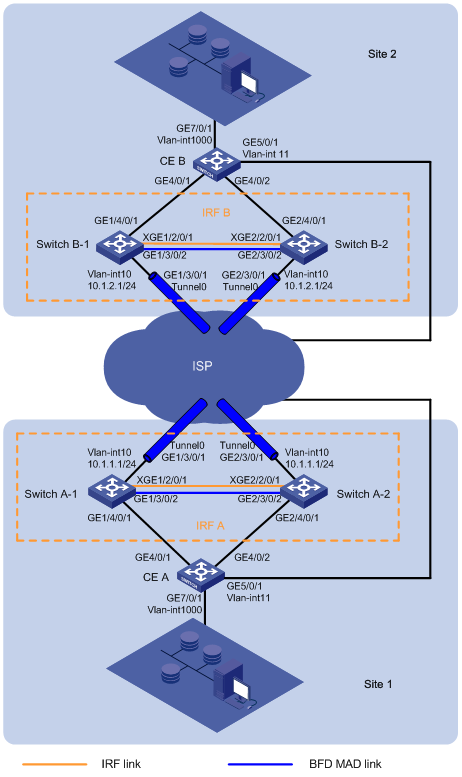
Table 2 IP address assignment
|
Device |
Interface |
IP address |
Device |
Interface |
IP address |
|
IRF A |
Loopback 0 |
1.1.1.1/32 |
IRF B |
Loopback 0 |
2.2.2.2/32 |
|
|
VLAN-interface 10 |
10.1.1.1/24 |
|
VLAN-interface 10 |
10.1.2.1/24 |
|
CE A |
VLAN-interface 11 |
11.1.1.1/24 |
CE B |
VLAN-interface 11 |
11.1.2.1/24 |
|
|
VLAN-interface 1000 |
100.0.0.1/24 |
|
VLAN-interface 1000 |
100.0.0.2/24 |
|
|
NOTE: · IP address of Loopback 0 is the source IP address of the EVI tunnel on each edge device. · VLAN-interface 10 and VLAN-interface 11 are interfaces connected to the transport network (the ISP network). |
Analysis
· To avoid IP address or gateway changes for virtual machines after inter-site migration, deploy VRRP as follows:
¡ Configure CE A and CE B to form a VRRP group to provide gateway services at the virtual IP address 100.0.0.254 for VLAN 1000.
¡ For CE A to become the master, assign a priority of 110 to CE A and configure CE B to use the default priority 100.
¡ For the EVI network to transmit VRRP protocol packets, enable selective flood for the destination MAC address of VRRP packets (0100-5e00-0012).
· For high availability, configure link aggregation for both uplinks and downlinks of the IRF fabrics.
Restrictions and guidelines
When you configure EVI with IRF, follow these restrictions and guidelines:
|
Configuration |
Restrictions and guidelines |
|
EVI network ID |
· All edge devices must use the same network ID for the EVI tunnels in the same EVI network. · The EVI tunnels on an edge device must use different network IDs. |
|
Extended VLAN |
· Extended VLANs assigned to different EVI networks cannot be duplicated. · To avoid data breach, ensure that all edge devices in an EVI network maintain the same extended VLANs. |
|
Outgoing interface to the transport network |
· For data security, do not use VLAN-interface 1 as an outgoing interface. Remove transport-facing physical interfaces from VLAN 1. · Do not use the VLAN interface of an extended VLAN as an outgoing interface to the transport network. |
|
IRF |
In IRF mode, any type of outbound policies (for example, the outbound QoS policy) on an interface does not take effect on packets that are received from an EVI tunnel. |
|
Spanning tree |
The spanning tree feature and BFD MAD are mutually exclusive. You must disable the spanning tree feature on the IRF fabrics. |
Procedures
Configuring IRF A
1. Connect IRF physical ports, as shown in Figure 2.
2. Configure IRF on Switch A-1:
# Assign member ID 1 to Switch A-1, and bind Ten-GigabitEthernet 2/0/1 to IRF-port 2.
<SwitchA-1> system-view
[SwitchA-1] irf member 1
[SwitchA-1] irf-port 2
[SwitchA-1-irf-port2] port group interface ten-gigabitethernet 2/0/1
[SwitchA-1-irf-port2] quit
[SwitchA-1] interface ten-gigabitethernet 2/0/1
[SwitchA-1-Ten-GigabitEthernet2/0/1] undo shutdown
[SwitchA-1-Ten-GigabitEthernet2/0/1] quit
# Save the configuration.
[SwitchA-1] save
The current configuration will be written to the device. Are you sure? [Y/N]:y
Please input the file name(*.cfg)[flash:/startup.cfg]
(To leave the existing filename unchanged, press the enter key):
flash:/startup.cfg exists, overwrite? [Y/N]:y
Validating file. Please wait...
Saved the current configuration to mainboard device successfully.
# Enable IRF mode.
[SwitchA-1] chassis convert mode irf
The device will switch to IRF mode and reboot. You are recommended to save the current running configuration and specify the configuration file for the next startup. Continue? [Y/N]:y
Do you want to convert the content of the next startup configuration file flash:/startup.cfg to make it available in IRF mode? [Y/N]:y
Please wait...
Saving the converted configuration file to the main board succeeded.
Slot 1:
Saving the converted configuration file succeeded.
Now rebooting, please wait...
Switch A-1 reboots to form a single-chassis IRF fabric.
3. Configure IRF on Switch A-2:
# Assign member ID 2 to Switch A-2, and bind Ten-GigabitEthernet 2/0/1 to IRF-port 1.
<SwitchA-2> system-view
[SwitchA-2] irf member 2
[SwitchA-2] irf-port 1
[SwitchA-2-irf-port1] port group interface ten-gigabitethernet 2/0/1
[SwitchA-2-irf-port1] quit
[SwitchA-2] interface ten-gigabitethernet 2/0/1
[SwitchA-2-Ten-GigabitEthernet2/0/1] undo shutdown
[SwitchA-2-Ten-GigabitEthernet2/0/1] quit
# Save the configuration.
[SwitchA-2] save
The current configuration will be written to the device. Are you sure? [Y/N]:y
Please input the file name(*.cfg)[flash:/startup.cfg]
(To leave the existing filename unchanged, press the enter key):
flash:/startup.cfg exists, overwrite? [Y/N]:y
Validating file. Please wait...
Saved the current configuration to mainboard device successfully.
# Enable IRF mode.
[SwitchA-2] chassis convert mode irf
The device will switch to IRF mode and reboot. You are recommended to save the current running configuration and specify the configuration file for the next startup. Continue? [Y/N]:y
Do you want to convert the content of the next startup configuration file flash:/startup.cfg to make it available in IRF mode? [Y/N]:y
Please wait...
Saving the converted configuration file to the main board succeeded.
Slot 1:
Saving the converted configuration file succeeded.
Now rebooting, please wait...
Switch A-2 reboots to form a two-chassis IRF fabric with Switch A-1.
4. Configure BFD MAD on IRF A:
# Log in to the IRF fabric and change its device name to IRFA. Set the domain ID of IRF A to 1.
<SwitchA-1> system-view
[SwitchA-1] sysname IRFA
[IRFA] irf domain 1
# Create VLAN 3, and assign GigabitEthernet 1/3/0/2 (on Switch A-1) and GigabitEthernet 2/3/0/2 (on Switch A-2) to VLAN 3.
[IRFA] vlan 3
[IRFA-vlan3] port gigabitethernet 1/3/0/2 gigabitethernet 2/3/0/2
[IRFA-vlan3] quit
# Create VLAN-interface 3, and configure a MAD IP address for each IRF member device on the VLAN interface.
[IRFA] interface vlan-interface 3
[IRFA-Vlan-interface3] mad bfd enable
[IRFA-Vlan-interface3] mad ip address 192.168.2.1 24 member 1
[IRFA-Vlan-interface3] mad ip address 192.168.2.2 24 member 2
[IRFA-Vlan-interface3] undo shutdown
[IRFA-Vlan-interface3] quit
# Disable the spanning tree feature on GigabitEthernet 1/3/0/2 and GigabitEthernet 2/3/0/2.
[IRFA] interface range gigabitethernet 1/3/0/2 gigabitethernet 2/3/0/2
[IRFA-if-range] undo stp enable
[IRFA-if-range] undo shutdown
[IRFA-if-range] quit
5. Assign IP addresses to interfaces and configure a routing protocol:
# Create VLAN 10, and assign an IP address to VLAN-interface 10.
[IRFA] vlan 10
[IRFA-vlan10] quit
[IRFA] interface vlan-interface 10
[IRFA-Vlan-interface10] ip address 10.1.1.1 24
[IRFA-Vlan-interface10] undo shutdown
[IRFA-Vlan-interface10] quit
# Create aggregate interface Bridge-Aggregation 1 (transport-facing), and assign the aggregate interface to VLAN 10.
[IRFA] interface bridge-aggregation 1
[IRFA-Bridge-Aggregation1] link-aggregation mode dynamic
[IRFA-Bridge-Aggregation1] port access vlan 10
[IRFA-Bridge-Aggregation1] undo shutdown
[IRFA-Bridge-Aggregation1] quit
# Assign GigabitEthernet 1/3/0/1 and GigabitEthernet 2/3/0/1 to aggregation group 1.
[IRFA] interface gigabitethernet 1/3/0/1
[IRFA-GigabitEthernet1/3/0/1] undo shutdown
[IRFA-GigabitEthernet1/3/0/1] port link-aggregation group 1
[IRFA-GigabitEthernet1/3/0/1] quit
[IRFA] interface gigabitethernet 2/3/0/1
[IRFA-GigabitEthernet2/3/0/1] undo shutdown
[IRFA-GigabitEthernet2/3/0/1] port link-aggregation group 1
[IRFA-GigabitEthernet2/3/0/1] quit
# Create VLAN 1000.
[IRFA] vlan 1000
[IRFA-vlan1000] quit
# Create aggregate interface Bridge-Aggregation 2 (site-facing), and assign the aggregate interface to VLAN 1000.
[IRFA] interface bridge-aggregation 2
[IRFA-Bridge-Aggregation2] link-aggregation mode dynamic
[IRFA-Bridge-Aggregation2] port link-type trunk
[IRFA-Bridge-Aggregation2] port trunk permit vlan 1000
[IRFA-Bridge-Aggregation2] undo shutdown
[IRFA-Bridge-Aggregation2] quit
# Assign GigabitEthernet 1/4/0/1 and GigabitEthernet 2/4/0/1 to aggregation group 2.
[IRFA] interface gigabitethernet 1/4/0/1
[IRFA-GigabitEthernet1/4/0/1] port link-aggregation group 2
[IRFA-GigabitEthernet1/4/0/1] undo shutdown
[IRFA-GigabitEthernet1/4/0/1] quit
[IRFA] interface gigabitethernet 2/4/0/1
[IRFA-GigabitEthernet2/4/0/1] port link-aggregation group 2
[IRFA-GigabitEthernet2/4/0/1] undo shutdown
[IRFA-GigabitEthernet2/4/0/1] quit
# Assign an IP address to Loopback 0.
[IRFA] interface loopback 0
[IRFA-LoopBack0] ip address 1.1.1.1 32
[IRFA-LoopBack0] quit
# Create an OSPF process (process 1 in this example), and enable OSPF on the loopback interface and VLAN-interface 10.
[IRFA] ospf 1
[IRFA-ospf-1] area 0
[IRFA-ospf-1-area-0.0.0.0] network 10.1.1.0 0.0.0.255
[IRFA-ospf-1-area-0.0.0.0] network 1.1.1.1 0.0.0.0
[IRFA-ospf-1-area-0.0.0.0] quit
[IRFA-ospf-1] quit
6. Configure EVI:
# Configure EVI tunnel 1 for EVI network 1.
[IRFA] interface Tunnel 1 mode evi
[IRFA-Tunnel1] source loopback 0
[IRFA-Tunnel1] evi network-id 1
# Configure IRF A as an ENDS for the EVI network.
[IRFA-Tunnel1] evi neighbor-discovery server enable
# Specify VLAN 1000 as an extended VLAN on the tunnel.
[IRFA-Tunnel1] evi extend-vlan 1000
# Enable selective flood for the MAC address 0100-5e00-0012.
[IRFA-Tunnel1] evi selective-flooding mac-address 0100-5e00-0012 vlan 1000
[IRFA-Tunnel1] quit
# Enable EVI and disable the spanning tree feature on the transport-facing physical interfaces GigabitEthernet 1/3/0/1 and GigabitEthernet 2/3/0/1.
[IRFA] interface gigabitethernet 1/3/0/1
[IRFA-GigabitEthernet1/3/0/1] evi enable
[IRFA-GigabitEthernet1/3/0/1] undo stp enable
[IRFA-GigabitEthernet1/3/0/1] quit
[IRFA] interface gigabitethernet 2/3/0/1
[IRFA-GigabitEthernet2/3/0/1] evi enable
[IRFA-GigabitEthernet2/3/0/1] undo stp enable
[IRFA-GigabitEthernet2/3/0/1] quit
Configuring CE A
1. Assign IP addresses to interfaces and configure a routing protocol:
# Create VLAN 11, and assign an IP address to VLAN-interface 11.
<CEA> system-view
[CEA] vlan 11
[CEA-vlan11] quit
[CEA] interface vlan-interface 11
[CEA-Vlan-interface11] ip address 11.1.1.1 24
[CEA-Vlan-interface11] undo shutdown
[CEA-Vlan-interface11] quit
# Assign the transport-facing interface GigabitEthernet 5/0/1 to VLAN 11.
[CEA] interface gigabitethernet 5/0/1
[CEA-GigabitEthernet5/0/1] port access vlan 11
[CEA-GigabitEthernet5/0/1] undo shutdown
[CEA-GigabitEthernet5/0/1] quit
# Create an OSPF process (process 1 in this example), and enable OSPF on VLAN-interface 11 and VLAN-interface 1000.
[CEA] ospf 1
[CEA-ospf-1] area 0
[CEA-ospf-1-area-0.0.0.0] network 11.1.1.0 0.0.0.255
[CEA-ospf-1-area-0.0.0.0] network 100.0.0.0 0.0.0.255
[CEA-ospf-1-area-0.0.0.0] quit
[CEA-ospf-1] quit
# Create VLAN 1000, and assign an IP address to VLAN-interface 1000. VLAN-interface 1000 is the gateway in site 2 for devices in VLAN 1000.
[CEA] vlan 1000
[CEA-vlan1000] quit
[CEA] interface vlan-interface 1000
[CEA-Vlan-interface1000] ip address 100.0.0.1 24
[CEA-Vlan-interface1000] undo shutdown
[CEA-Vlan-interface1000] quit
# Set up the link aggregation between CE A and IRF A, and assign the aggregate interface to VLAN 1000.
[CEA] interface bridge-aggregation 2
[CEA-Bridge-Aggregation2] link-aggregation mode dynamic
[CEA-Bridge-Aggregation2] port link-type trunk
[CEA-Bridge-Aggregation2] port trunk permit vlan 1000
[CEA-Bridge-Aggregation2] quit
[CEA] interface gigabitethernet 4/0/1
[CEA-GigabitEthernet4/0/1] port link-aggregation group 2
[CEA-GigabitEthernet4/0/1] undo shutdown
[CEA-GigabitEthernet4/0/1] quit
[CEA] interface gigabitethernet 4/0/2
[CEA-GigabitEthernet4/0/2] port link-aggregation group 2
[CEA-GigabitEthernet4/0/2] undo shutdown
[CEA-GigabitEthernet4/0/2] quit
# Assign the site-facing interface GigabitEthernet 7/0/1 to VLAN 1000.
[CEA] interface gigabitethernet 7/0/1
[CEA-GigabitEthernet7/0/1] port link-type trunk
[CEA-GigabitEthernet7/0/1] port trunk permit vlan 1000
[CEA-GigabitEthernet7/0/1] undo shutdown
[CEA] quit
2. Add CE A to VRRP group 1:
# Configure VRRP group 1 on VLAN-interface 1000.
[CEA] interface vlan-interface 1000
[CEA-Vlan-interface1000] vrrp vrid 1 virtual-ip 100.0.0.254
# Assign a priority of 110 to CE A in the VRRP group.
[CEA-Vlan-interface1000] vrrp vrid 1 priority 110
[CEA-Vlan-interface1000] quit
Configuring IRF B
1. Connect IRF physical ports, as shown in Figure 2.
2. Configure IRF on Switch B-1:
# Assign the member ID 1 to Switch B-1, and bind Ten-GigabitEthernet 2/0/1 to IRF-port 2.
<SwitchB-1> system-view
[SwitchB-1] irf member 1.
[SwitchB-1] irf-port 2
[SwitchB-1-irf-port2] port group interface ten-GigabitEthernet 2/0/1
[SwitchB-1-irf-port2] quit
[SwitchB-1] interface ten-GigabitEthernet 2/0/1
[SwitchB-1-Ten-GigabitEthernet2/0/1] undo shutdown
[SwitchB-1-Ten-GigabitEthernet2/0/1] quit
# Save the configuration.
[SwitchB-1] save
The current configuration will be written to the device. Are you sure? [Y/N]:y
Please input the file name(*.cfg)[flash:/startup.cfg]
(To leave the existing filename unchanged, press the enter key):
flash:/startup.cfg exists, overwrite? [Y/N]:y
Validating file. Please wait...
Saved the current configuration to mainboard device successfully.
# Enable IRF mode.
[SwitchB-1] chassis convert mode irf
The device will switch to IRF mode and reboot. You are recommended to save the current running configuration and specify the configuration file for the next startup. Continue? [Y/N]:y
Do you want to convert the content of the next startup configuration file flash:/startup.cfg to make it available in IRF mode? [Y/N]:y
Please wait...
Saving the converted configuration file to the main board succeeded.
Slot 1:
Saving the converted configuration file succeeded.
Now rebooting, please wait...
Switch B-1 reboots to form a single-chassis IRF fabric.
3. Configure IRF on Switch B-2:
# Assign the member ID 2 to Switch B-2, and bind Ten-GigabitEthernet 2/0/1 to IRF-port 1.
<SwitchB-2> system-view
[SwitchB-2] irf member 2
[SwitchB-2] irf-port 1
[SwitchB-2-irf-port1] port group interface ten-GigabitEthernet 2/0/1
[SwitchB-2-irf-port1] quit
[SwitchB-2] interface ten-GigabitEthernet 2/0/1
[SwitchB-2-Ten-GigabitEthernet2/0/1] undo shutdown
[SwitchB-2-Ten-GigabitEthernet2/0/1] quit
# Save the configuration.
[SwitchB-2] save
The current configuration will be written to the device. Are you sure? [Y/N]:y
Please input the file name(*.cfg)[flash:/startup.cfg]
(To leave the existing filename unchanged, press the enter key):
flash:/startup.cfg exists, overwrite? [Y/N]:y
Validating file. Please wait...
Saved the current configuration to mainboard device successfully.
# Enable IRF mode.
[SwitchB-2] chassis convert mode irf
The device will switch to IRF mode and reboot. You are recommended to save the current running configuration and specify the configuration file for the next startup. Continue? [Y/N]:y
Do you want to convert the content of the next startup configuration file flash:/startup.cfg to make it available in IRF mode? [Y/N]:y
Please wait...
Saving the converted configuration file to the main board succeeded.
Slot 1:
Saving the converted configuration file succeeded.
Now rebooting, please wait...
Switch B-2 reboots to form a two-chassis IRF fabric with Switch B-1.
4. Configure BFD MAD on IRF B:
# Log in to the IRF fabric and change its device name to IRFB. Set the domain ID to 2 for IRF B.
<SwitchB-1> system-view
[SwitchB-1] sysname IRFB
[IRFB] irf domain 2
# Create VLAN 3, and assign GigabitEthernet 1/3/0/2 (on Switch B-1) and GigabitEthernet 2/3/0/2 (Switch B-2) to VLAN 3.
[IRFB] vlan 3
[IRFB-vlan3] port gigabitethernet 1/3/0/2 gigabitethernet 2/3/0/2
[IRFB-vlan3] quit
# Create VLAN-interface 3, and configure a MAD IP address for each IRF member device on the VLAN interface.
[IRFB] interface vlan-interface 3
[IRFB-Vlan-interface3] mad bfd enable
[IRFB-Vlan-interface3] mad ip address 192.168.2.1 24 member 1
[IRFB-Vlan-interface3] mad ip address 192.168.2.2 24 member 2
[IRFB-Vlan-interface3] undo shutdown
[IRFB-Vlan-interface3] quit
# Disable the spanning tree feature on GigabitEthernet 1/3/0/2 and GigabitEthernet 2/3/0/2.
[IRFB] interface range gigabitethernet 1/3/0/2 gigabitethernet 2/3/0/2
[IRFB-if-range] undo stp enable
[IRFB-if-range] undo shutdown
[IRFB-if-range] quit
5. Assign IP addresses to interfaces and configure a routing protocol:
# Create VLAN 10, and assign an IP address to VLAN-interface 10.
[IRFB] vlan 10
[IRFB-vlan10] quit
[IRFB] interface vlan-interface 10
[IRFB-Vlan-interface10] ip address 10.1.2.1 24
[IRFB-Vlan-interface10] undo shutdown
[IRFB-Vlan-interface10] quit
# Create aggregate interface Bridge-Aggregation 1 (transport-facing), and assign the aggregate interface to VLAN 10.
[IRFB] interface bridge-aggregation 1
[IRFB-Bridge-Aggregation1] link-aggregation mode dynamic
[IRFB-Bridge-Aggregation1] port access vlan 10
[IRFB-Bridge-Aggregation1] undo shutdown
[IRFB-Bridge-Aggregation1] quit
# Assign GigabitEthernet 1/3/0/1 and GigabitEthernet 2/3/0/1 to aggregation group 1.
[IRFB] interface gigabitethernet 1/3/0/1
[IRFB-GigabitEthernet1/3/0/1] undo shutdown
[IRFB-GigabitEthernet1/3/0/1] port link-aggregation group 1
[IRFB-GigabitEthernet1/3/0/1] quit
[IRFB] interface gigabitethernet 2/3/0/1
[IRFB-GigabitEthernet2/3/0/1] undo shutdown
[IRFB-GigabitEthernet2/3/0/1] port link-aggregation group 1
[IRFB-GigabitEthernet2/3/0/1] quit
# Create VLAN 1000.
[IRFB] vlan 1000
[IRFB-vlan1000] quit
# Create aggregate interface Bridge-Aggregation 2 (site-facing), and assign the aggregate interface to VLAN 1000.
[IRFB] interface bridge-aggregation 2
[IRFB-Bridge-Aggregation2] link-aggregation mode dynamic
[IRFB-Bridge-Aggregation2] port link-type trunk
[IRFB-Bridge-Aggregation2] port trunk permit vlan 1000
[IRFB-Bridge-Aggregation2] undo shutdown
[IRFB-Bridge-Aggregation2] quit
# Assign GigabitEthernet 1/4/0/1 and GigabitEthernet 2/4/0/1 to aggregation group 2.
[IRFB] interface gigabitethernet 1/4/0/1
[IRFB-GigabitEthernet1/4/0/1] port link-aggregation group 2
[IRFB-GigabitEthernet1/4/0/1] undo shutdown
[IRFB-GigabitEthernet1/4/0/1] quit
[IRFB] interface gigabitethernet 2/4/0/1
[IRFB-GigabitEthernet2/4/0/1] port link-aggregation group 2
[IRFB-GigabitEthernet2/4/0/1] undo shutdown
[IRFB-GigabitEthernet2/4/0/1] quit
# Assign an IP address to Loopback 0.
[IRFB] interface loopback 0
[IRFB-LoopBack0] ip address 2.2.2.2 32
[IRFB-LoopBack0] quit
# Create an OSPF process (process 1 in this example), and enable OSPF on the loopback interface and VLAN-interface 10.
[IRFB] ospf 1
[IRFB-ospf-1] area 0
[IRFB-ospf-1-area-0.0.0.0] network 10.1.2.0 0.0.0.255
[IRFB-ospf-1-area-0.0.0.0] network 2.2.2.2 0.0.0.0
[IRFB-ospf-1-area-0.0.0.0] quit
[IRFB-ospf-1] quit
6. Configure EVI:
# Configure EVI tunnel 1 for EVI network 1.
[IRFB] interface Tunnel 1 mode evi
[IRFB-Tunnel1] source loopback 0
[IRFB-Tunnel1] evi network-id 1
# Configure IRF B as an ENDC of IRF A.
[IRFB-Tunnel1] evi neighbor-discovery client enable 1.1.1.1
# Specify VLAN 1000 as an extended VLAN on the tunnel.
[IRFB-Tunnel1] evi extend-vlan 1000
# Enable selective flood for MAC address 0100-5e00-0012.
[IRFB-Tunnel1] evi selective-flooding mac-address 0100-5e00-0012 vlan 1000
[IRFB-Tunnel1] quit
# Enable EVI and disable the spanning tree feature on the transport-facing physical interfaces GigabitEthernet 1/3/0/1 and GigabitEthernet 2/3/0/1.
[IRFB] interface gigabitethernet 1/3/0/1
[IRFB-GigabitEthernet1/3/0/1] evi enable
[IRFB-GigabitEthernet1/3/0/1] undo stp enable
[IRFB-GigabitEthernet1/3/0/1] quit
[IRFB] interface gigabitethernet 2/3/0/1
[IRFB-GigabitEthernet2/3/0/1] evi enable
[IRFB-GigabitEthernet2/3/0/1] undo stp enable
[IRFB-GigabitEthernet2/3/0/1] quit
Configure CE B
1. Assign IP addresses to interfaces and configure a routing protocol:
# Create VLAN 11, and assign an IP address to VLAN-interface 11.
<CEB> system-view
[CEB] vlan 11
[CEB-vlan11] quit
[CEB] interface vlan-interface 11
[CEB-Vlan-interface11] ip address 11.1.2.1 24
[CEB-Vlan-interface11] undo shutdown
[CEB-Vlan-interface11] quit
# Assign the transport-facing interface GigabitEthernet 5/0/1 to VLAN 11.
[CEB] interface gigabitethernet 5/0/1
[CEB-GigabitEthernet5/0/1] port access vlan 11
[CEB-GigabitEthernet5/0/1] undo shutdown
[CEB-GigabitEthernet5/0/1] quit
# Create an OSPF process (process 1 in this example), and enable OSPF on VLAN-interface 11 and VLAN-interface 1000.
[CEB] ospf 1
[CEB-ospf-1] area 0
[CEB-ospf-1-area-0.0.0.0] network 11.1.2.0 0.0.0.255
[CEB-ospf-1-area-0.0.0.0] network 100.0.0.0 0.0.0.255
[CEB-ospf-1-area-0.0.0.0] quit
[CEB-ospf-1] quit
# Create VLAN 1000, and assign an IP address to VLAN-interface 1000. VLAN-interface 1000 is the gateway in site 2 for devices in VLAN 1000.
[CEB] vlan 1000
[CEB-vlan1000] quit
[CEB] interface vlan-interface 1000
[CEB-Vlan-interface1000] ip address 100.0.0.2 24
[CEB-Vlan-interface1000] undo shutdown
[CEB-Vlan-interface1000] quit
# Set up the link aggregation between CE B and IRF B, and assign the aggregate interface to VLAN 1000.
[CEB] interface bridge-aggregation 2
[CEB-Bridge-Aggregation2] link-aggregation mode dynamic
[CEB-Bridge-Aggregation2] port link-type trunk
[CEB-Bridge-Aggregation2] port trunk permit vlan 1000
[CEB-Bridge-Aggregation2] quit
[CEB] interface gigabitethernet 4/0/1
[CEB-GigabitEthernet4/0/1] port link-aggregation group 2
[CEB-GigabitEthernet4/0/1] undo shutdown
[CEB-GigabitEthernet4/0/1] quit
[CEB] interface gigabitethernet 4/0/2
[CEB-GigabitEthernet4/0/2] port link-aggregation group 2
[CEB-GigabitEthernet4/0/2] undo shutdown
[CEB-GigabitEthernet4/0/2] quit
# Assign the site-facing interface GigabitEthernet 7/0/1 to VLAN 1000.
[CEB] interface gigabitethernet 7/0/1
[CEB-GigabitEthernet7/0/1] port link-type trunk
[CEB-GigabitEthernet7/0/1] port trunk permit vlan 1000
[CEB-GigabitEthernet7/0/1] undo shutdown
[CEB] quit
2. Configure VRRP group 1 on VLAN-interface 1000 to add CE B to VRRP group 1.
[CEB] interface vlan-interface 1000
[CEB-Vlan-interface1000] vrrp vrid 1 virtual-ip 100.0.0.254
[CEB-Vlan-interface1000] quit
|
|
NOTE: The virtual IP address of the VRRP group must be the same as the address configured for VRRP group 1 on CE A. |
Verifying the configuration
# Move a server (100.0.0.100) from site 1 to site 2 without changing its IP address. (Details not shown.)
# Verify that the server can be pinged.
C:\>ping 100.0.0.100
Pinging 100.0.0.100 with 32 bytes of data:
Reply from 100.0.0.100: bytes=32 time=1ms TTL=128
Reply from 100.0.0.100: bytes=32 time=37ms TTL=128
Reply from 100.0.0.100: bytes=32 time=1ms TTL=128
Reply from 100.0.0.100: bytes=32 time=1ms TTL=128
Ping statistics for 100.0.0.100:
Packets: Sent = 4, Received = 4, Lost = 0 (0% loss),
Approximate round trip times in milli-seconds:
Minimum = 1ms, Maximum = 37ms, Average = 10ms
C:\>
Configuration files
· IRF A:
#
sysname IRFA
#
vlan 1
#
vlan 3
#
vlan 10
#
vlan 1000
#
irf-port 1/2
port group mdc 1 interface Ten-GigabitEthernet1/2/0/1
#
irf-port 2/1
port group mdc 1 interface Ten-GigabitEthernet2/2/0/1
#
interface Bridge-Aggregation1
port access vlan 10
link-aggregation mode dynamic
#
interface Bridge-Aggregation2
port link-type trunk
port trunk permit vlan 1 1000
link-aggregation mode dynamic
#
interface LoopBack0
ip address 1.1.1.1 255.255.255.255
#
interface Vlan-interface3
mad bfd enable
mad ip address 192.168.2.1 255.255.255.0 member 1
mad ip address 192.168.2.2 255.255.255.0 member 2
#
interface Vlan-interface10
ip address 10.1.1.1 255.255.255.0
#
interface GigabitEthernet1/3/0/1
port link-mode bridge
port access vlan 10
undo stp enable
evi enable
port link-aggregation group 1
#
interface GigabitEthernet2/3/0/1
port link-mode bridge
port access vlan 10
undo stp enable
evi enable
port link-aggregation group 1
#
interface GigabitEthernet1/3/0/2
port link-mode bridge
port access vlan 3
undo stp enable
#
interface GigabitEthernet2/3/0/2
port link-mode bridge
port access vlan 3
undo stp enable
#
interface GigabitEthernet1/4/0/1
port link-mode bridge
port link-aggregation group 2
#
interface GigabitEthernet2/4/0/1
port link-mode bridge
port link-aggregation group 2
#
interface Ten-GigabitEthernet1/2/0/1
#
interface Tunnel1 mode evi
evi selective-flooding mac-address 0100-5e00-0012 vlan 1000
evi extend-vlan 1000
source LoopBack0
evi network-id 1
evi neighbor-discovery server enable
#
ospf 1
area 0.0.0.0
network 1.1.1.1 0.0.0.0
network 10.1.1.0 0.0.0.255
#
return
· CE A:
#
sysname CEA
#
vlan 1
#
vlan 11
#
vlan 1000
#
interface Bridge-Aggregation2
port link-type trunk
port trunk permit vlan 1 1000
link-aggregation mode dynamic
#
interface Vlan-interface11
ip address 11.1.1.1 255.255.255.0
#
interface Vlan-interface1000
ip address 100.0.0.1 255.255.255.0
vrrp vrid 1 virtual-ip 100.0.0.254
vrrp vrid 1 priority 110
#
interface GigabitEthernet4/0/1
port link-mode bridge
port link-aggregation group 2
#
interface GigabitEthernet4/0/2
port link-mode bridge
port link-aggregation group 2
#
interface GigabitEthernet5/0/1
port link-mode bridge
port access vlan 11
#
interface GigabitEthernet7/0/1
port link-mode bridge
port link-type trunk
port trunk permit vlan 1 1000
#
ospf 1
area 0.0.0.0
network 11.1.1.0 0.0.0.255
network 100.0.0.0 0.0.0.255
#
return
· IRF B:
#
sysname IRFB
#
vlan 1
#
vlan 3
#
vlan 10
#
vlan 1000
#
irf-port 1/2
port group mdc 1 interface Ten-GigabitEthernet1/2/0/1
#
irf-port 2/1
port group mdc 1 interface Ten-GigabitEthernet2/2/0/1
#
interface Bridge-Aggregation1
port access vlan 10
link-aggregation mode dynamic
#
interface Bridge-Aggregation2
port link-type trunk
port trunk permit vlan 1 1000
link-aggregation mode dynamic
#
interface LoopBack0
ip address 2.2.2.2 255.255.255.255
#
interface Vlan-interface3
mad bfd enable
mad ip address 192.168.2.1 255.255.255.0 member 1
mad ip address 192.168.2.2 255.255.255.0 member 2
#
interface Vlan-interface10
ip address 10.1.2.1 255.255.255.0
#
interface GigabitEthernet1/3/0/1
port link-mode bridge
port access vlan 10
undo stp enable
evi enable
port link-aggregation group 1
#
interface GigabitEthernet2/3/0/1
port link-mode bridge
port access vlan 10
undo stp enable
evi enable
port link-aggregation group 1
#
interface GigabitEthernet1/3/0/2
port link-mode bridge
port access vlan 3
undo stp enable
#
interface GigabitEthernet2/3/0/2
port link-mode bridge
port access vlan 3
undo stp enable
#
interface GigabitEthernet1/4/0/1
port link-mode bridge
port link-aggregation group 2
#
interface GigabitEthernet2/4/0/1
port link-mode bridge
port link-aggregation group 2
#
interface Ten-GigabitEthernet1/2/0/1
#
interface Tunnel1 mode evi
evi selective-flooding mac-address 0100-5e00-0012 vlan 1000
evi extend-vlan 1000
source LoopBack0
evi network-id 1
evi neighbor-discovery client enable 1.1.1.1
#
ospf 1
area 0.0.0.0
network 2.2.2.2 0.0.0.0
network 10.1.2.0 0.0.0.255
#
return
· CE B:
#
sysname CEB
#
vlan 1
#
vlan 11
#
vlan 1000
#
stp global enable
#
interface Bridge-Aggregation2
port link-type trunk
port trunk permit vlan 1 1000
link-aggregation mode dynamic
#
interface Vlan-interface11
ip address 11.1.2.1 255.255.255.0
#
interface Vlan-interface1000
ip address 100.0.0.2 255.255.255.0
vrrp vrid 1 virtual-ip 100.0.0.254
#
interface GigabitEthernet4/0/1
port link-mode bridge
port link-aggregation group 2
#
interface GigabitEthernet4/0/2
port link-mode bridge
port link-aggregation group 2
#
interface GigabitEthernet5/0/1
port link-mode bridge
port access vlan 11
#
interface GigabitEthernet7/0/1
port link-mode bridge
port link-type trunk
port trunk permit vlan 1 1000
#
ospf 1
area 0.0.0.0
network 11.1.2.0 0.0.0.255
network 100.0.0.0 0.0.0.255
#
return
Related documentation
· H3C S7500E Switch Series EVI Command Reference-R758X
· H3C S7500E Switch Series EVI Configuration Guide-R758X
· H3C S7500E Switch Series Virtual Technologies Command Reference-R758X
· H3C S7500E Switch Series Virtual Technologies Configuration Guide-R758X
