- Table of Contents
-
- 11-Network Management and Monitoring Configuration Examples
- 01-H3C_NQA_Configuration_Examples
- 02-H3C_NTP_Configuration_Examples
- 03-H3C_SNMP_Configuration_Examples
- 04-H3C_EAA_Configuration_Examples
- 05-H3C_Mirroring_Configuration_Examples
- 06-H3C_NetStream_Configuration_Examples
- 07-H3C_sFlow_Configuration_Examples
- Related Documents
-
| Title | Size | Download |
|---|---|---|
| 06-H3C_NetStream_Configuration_Examples | 407.96 KB |
|
|
|
H3C NetStream Configuration Examples |
|
|
|
|
|
|
Software version: 6W100-20200330
Document version: Release 7585P05
Copyright © 2020 New H3C Technologies Co., Ltd. All rights reserved.
No part of this manual may be reproduced or transmitted in any form or by any means without prior written consent of New H3C Technologies Co., Ltd.
Except for the trademarks of New H3C Technologies Co., Ltd., any trademarks that may be mentioned in this document are the property of their respective owners.
The information in this document is subject to change without notice.
Contents
General restrictions and guidelines
Example: Configuring IPv4 NetStream
Configuring the NetStream server
Example: Configuring IPv6 NetStream
Configuring the NetStream server
Introduction
This document provides IPv4 NetStream and IPv6 NetStream configuration examples.
Prerequisites
The configuration examples in this document were created and verified in a lab environment, and all the devices were started with the factory default configuration. When you are working on a live network, make sure you understand the potential impact of every command on your network.
This document assumes that you have basic knowledge of NetStream.
General restrictions and guidelines
The NetStream feature is available on the following interface modules:
· SD, EB, and EC.
· LSQ3GV48SC0.
· LSQ1TGS8SC0.
Example: Configuring IPv4 NetStream
Network configuration
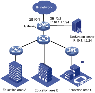
As shown in Figure 1, configure IPv4 NetStream on the gateway to monitor traffic and user behavior of internal users in the education areas.
Restrictions and guidelines
When you configure IPv4 NetStream, follow these restrictions and guidelines:
· You must specify the UDP port number of the NetStream server as the destination UDP port for NetStream data export.
· In this example, the NetStream server runs IMC PLAT 7.0 (E0202).
Procedures
Configuring the gateway
# Mirror both incoming and outgoing traffic on GigabitEthernet 1/0/1.
[Gateway] interface gigabitethernet 1/0/1
[Gateway-GigabitEthernet1/0/1] ip netstream inbound
[Gateway-GigabitEthernet1/0/1] ip netstream outbound
[Gateway-GigabitEthernet1/0/1] quit
# Specify GigabitEthernet 1/0/2 as the source interface for NetStream traditional data packets.
[Gateway] interface gigabitethernet 1/0/2
[Gateway-GigabitEthernet1/0/2] ip address 10.1.1.1 255.255.255.0
[Gateway-GigabitEthernet1/0/2] quit
[Gateway] ip netstream export source interface gigabitethernet 1/0/2
# Specify the destination host as 10.1.1.2 and UDP port 5000.
[Gateway] ip netstream export host 10.1.1.2 5000
Configuring the NetStream server
Adding the gateway to the NetStream server
1. Click the Service tab.
2. From the navigation tree, select Traffic Analysis and Audit > Settings.
3. In the Guide to Quick Traffic Analysis And Audit Configuration area, click Device Management.
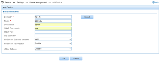
4. In the Device List area, click Add.
5. Add the gateway, as shown in Figure 2.
Deploying the server configuration
1. Click the Service tab.
2. From the navigation tree, select Traffic Analysis and Audit > Settings.
3. In the Guide to Quick Traffic Analysis And Audit Configuration area, click Server Management.
4.
In the Server List area, click the Modify icon
![]() .
.
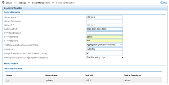
5. Configure the NetStream server parameters, as shown in Figure 3.
6. Click Deploy.
Figure 3 Deploying the server configuration
Adding an interface traffic analysis task
You can add multiple types of traffic analysis tasks. This example uses the interface traffic analysis task type.
1. Click the Service tab.
2. From the navigation tree, select Traffic Analysis and Audit > Settings.
3. In the Guide to Quick Traffic Analysis And Audit Configuration area, click Traffic Analysis Task Management.
4. In the Traffic Analysis Task List area, click Add.
5. In the Select Task Type area, select Interface, and click Next.
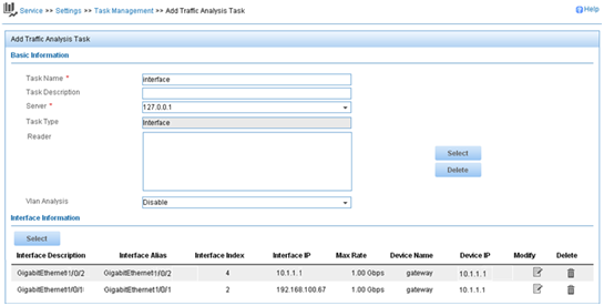
6. Configure basic task parameters, select interfaces, and click OK, as shown in Figure 4.
Figure 4 Adding an interface traffic analysis task
Verifying the configuration
1. Verify that the gateway exports NetStream data to the NetStream server.
[Gateway] display ip netstream export
IP export information:
Flow source interface : GigabitEthernet1/0/2
Flow destination VPN instance : Not specified
Flow destination IP address (UDP) : 10.1.1.2 (5000)
Version 5 exported flow number : 0
Version 5 exported UDP datagram number (failed) : 0 (0)
Version 9 exported flow number : 0
Version 9 exported UDP datagram number (failed) : 0 (0)
Version 10 exported flow number : 0
Version 10 exported UDP datagram number (failed): 0 (0)
L2 export information:
Flow source interface : GigabitEthernet1/0/2
Flow destination VPN instance : Not specified
Flow destination IP address (UDP) : 10.1.1.2 (5000)
Version 9 exported flow number : 0
Version 9 exported UDP datagram number (failed) : 0 (0)
Version 10 exported flow number : 0
Version 10 exported UDP datagram number (failed): 0 (0)
2. Display the report of an interface traffic analysis task:
a. Click the Service tab.
b. From the navigation tree, select Traffic Analysis and Audit > Interface Traffic Analysis Task.
c. Click the Expand icon next to Interface Traffic Analysis Task, and select interface from the shortcut menu.
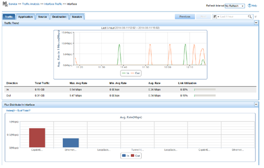
The Traffic tab page displays interface traffic statistics for the task, as shown in Figure 5.
Figure 5 Interface traffic analysis
Configuration files
interface GigabitEthernet1/0/2
ip address 10.1.1.1 255.255.255.0
#
interface GigabitEthernet1/0/1
ip netstream inbound
ip netstream outbound
#
ip netstream export host 10.1.1.2 5000
ip netstream export source interface GigabitEthernet1/0/2
#
Example: Configuring IPv6 NetStream
Network configuration
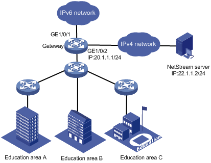
As shown in Figure 6, configure IPv6 NetStream on the gateway to monitor traffic and user behavior of internal users in the education areas.
Software version used
This configuration example was created and verified on S7500E-CMW710-R7577P01.
Restrictions and guidelines
When you configure IPv6 NetStream, follow these restrictions and guidelines:
· You must specify the UDP port number of the NetStream server as the destination UDP port for IPv6 NetStream data export.
· In this example, the NetStream server runs IMC PLAT 7.0 (E0202).
Procedures
Configuring the gateway
# Assign an IP address to the NetStream server. Make sure the gateway and NetStream server can reach each other. (Details not shown.)
# Enable IPv6 NetStream for both incoming and outgoing traffic on GigabitEthernet 1/0/1.
<Gateway> system-view
[Gateway] interface GigabitEthernet 1/0/1
[Gateway-GigabitEthernet1/0/1] ipv6 netstream inbound
[Gateway-GigabitEthernet1/0/1] ipv6 netstream outbound
[Gateway-GigabitEthernet1/0/1] quit
# Assign an IP address to GigabitEthernet 1/0/2.
[Gateway] interface gigabitethernet 1/0/2
[Gateway-GigabitEthernet1/0/2] ip address 20.1.1.1 255.255.255.0
[Gateway-GigabitEthernet1/0/2] quit
# Specify GigabitEthernet 1/0/2 as the source interface for IPv6 NetStream data packets.
[Gateway] ipv6 netstream export source interface GigabitEthernet 1/0/2
# Specify the destination host as 22.1.1.2 and UDP port 5000.
[Gateway] ipv6 netstream export host 22.1.1.2 5000
Configuring the NetStream server
Adding the gateway to the NetStream server
1. Click the Service tab.
2. From the navigation tree, select Traffic Analysis and Audit > Settings.
3. In the Guide to Quick Traffic Analysis And Audit Configuration area, click Device Management.
4. In the Device List area, click Add.
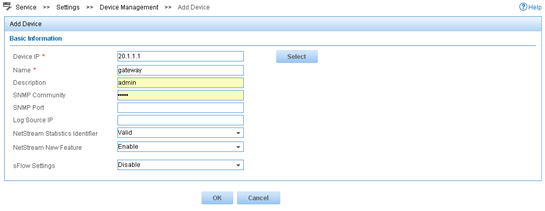
5. Add the gateway, as shown in Figure 7.
Deploying the server configuration
1. Click the Service tab.
2. From the navigation tree, select Traffic Analysis and Audit > Settings.
3. In the Guide to Quick Traffic Analysis And Audit Configuration area, click Server Management.
4.
In the Server List area, click the Modify icon
![]() .
.
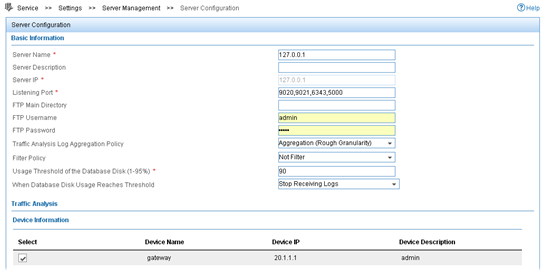
5. Configure the NetStream server parameters, as shown in Figure 8.
6. Click Deploy.
Figure 8 Deploying the server configuration
Adding an interface traffic analysis task
You can add multiple types of traffic analysis tasks. This example uses the interface traffic analysis task type.
1. Click the Service tab.
2. From the navigation tree, select Traffic Analysis and Audit > Settings.
3. In the Guide to Quick Traffic Analysis And Audit Configuration area, click Traffic Analysis Task Management.
4. In the Traffic Analysis Task List area, click Add.
5. In the Select Task Type area, select Interface, and click Next.
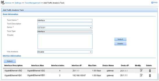
6. Configure basic task parameters, select interfaces, and click OK, as shown in Figure 9.
Figure 9 Adding an interface traffic analysis task
Verifying the configuration
1. Verify that the gateway exports IPv6 NetStream data to the NetStream server.
[Gateway] display ipv6 netstream export
IPv6 export information:
Flow source interface : GigabitEthernet1/0/2
Flow destination VPN instance : Not specified
Flow destination IP address (UDP) : 22.1.1.2 (5000)
Version 9 exported flow number : 0
Version 9 exported UDP datagram number (failed) : 0 (0)
Version 10 exported flow number : 0
Version 10 exported UDP datagram number (failed): 0 (0)
2. Display the report of an interface traffic analysis task:
a. Click the Service tab.
b. From the navigation tree, select Traffic Analysis and Audit > Interface Traffic Analysis Task.
c. Click the Expand icon next to Interface Traffic Analysis Task, and select interface from the shortcut menu.
The Traffic tab page displays interface traffic statistics for the task, as shown in Figure 10.
Figure 10 Interface traffic analysis
Configuration files
#
interface GigabitEthernet1/0/2
ip address 20.1.1.1 255.255.255.0
#
interface GigabitEthernet1/0/1
ipv6 netstream inbound
ipv6 netstream outbound
#
ipv6 netstream export host 22.1.1.2 5000
ipv6 netstream export source interface GigabitEthernet1/0/2
Related documentation
· H3C S7500E Switch Series Network Management and Monitoring Configuration Guide-R758X
· H3C S7500E Switch Series Network Management and Monitoring Command Reference-R758X