- Table of Contents
-
- 10-High Availability Configuration Examples
- 01-H3C_Ethernet_OAM_Configuration_Examples
- 02-H3C_CFD_Configuration_Examples
- 03-H3C_DLDP_Configuration_Examples
- 04-H3C_RRPP_configuration_examples
- 05-H3C_Smart_Link_Configuration_Examples
- 06-H3C_VRRP_Configuration_Examples
- 07-H3C_BFD_Configuration_Examples
- Related Documents
-
| Title | Size | Download |
|---|---|---|
| 04-H3C_RRPP_configuration_examples | 503.59 KB |
|
|
|
H3C RRPP Configuration Examples |
|
|
|
|
Software version: Release 7585P05
Document version: 6W100-20200330
Copyright © 2020 New H3C Technologies Co., Ltd. All rights reserved.
No part of this manual may be reproduced or transmitted in any form or by any means without prior written consent of New H3C Technologies Co., Ltd.
Except for the trademarks of New H3C Technologies Co., Ltd., any trademarks that may be mentioned in this document are the property of their respective owners.
The information in this document is subject to change without notice.
Contents
General restrictions and guidelines
Example: Configuring a single ring
Example: Configuring intersecting rings
Example: Configuring dual-homed intersecting rings
Introduction
This document provides RRPP configuration examples.
Prerequisites
The configuration examples in this document were created and verified in a lab environment, and all the devices were started with the factory default configuration. When you are working on a live network, make sure you understand the potential impact of every command on your network.
This document assumes that you have basic knowledge of RRPP.
General restrictions and guidelines
When you configure RRPP, follow these restrictions and guidelines:
· Do not configure the default VLAN of a port accessing an RRPP ring as the control VLAN, and do not enable QinQ or VLAN mapping on control VLANs. If you do, RRPPDUs cannot be correctly forwarded.
· To prevent temporary broadcast storms, do not enable the OAM remote loopback feature on an RRPP port.
Example: Configuring a single ring
Network configuration
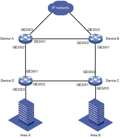
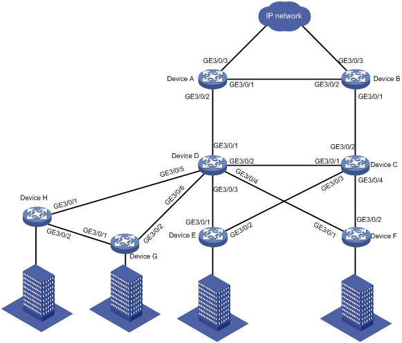
As shown in Figure 1, area A and area B are connected to a ring-shaped distribution layer network. Configure RRPP to implement the following requirements in the network:
· Eliminate loops and implement link recovery in the Layer 2 network.
· Implement link load balancing by forwarding voice traffic in VLAN 100 through VLAN 150 and video traffic in VLAN 151 through VLAN 200.
· Improve RRPP topology convergence speed by setting the physical state change suppression interval to 0 seconds for all Ethernet interfaces on the RRPP ring.
Analysis
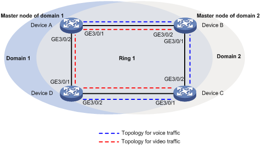
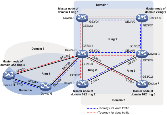
For voice and video traffic to be forwarded in different topologies, create two RRPP domains.
· In RRPP domain 1, specify VLAN 100 through VLAN 150 as protected VLANs, and specify Device A as the master node.
· In RRPP domain 2, specify VLAN 151 through VLAN 200 as protected VLANs, and specify Device B as the master node.
To implement load balancing for voice and video traffic, perform the following tasks:
· On Device A, specify GigabitEthernet 3/0/1 as the primary port, and GigabitEthernet 3/0/2 as the secondary port.
· On Device B, specify GigabitEthernet 3/0/2 as the primary port, and GigabitEthernet 3/0/1 as the secondary port.
Figure 2 Topologies for voice and video traffic
Restrictions and guidelines
When you configure a single RRPP ring, follow these restrictions and guidelines:
· After you configure RRPP rings for an RRPP domain, you cannot delete or modify the primary control VLAN of the domain. You can only use the undo control-vlan command to delete a primary control VLAN.
· When you configure load balancing, you must configure different protected VLANs for different RRPP domains.
Procedures
Configuring Device A
# Create VLANs 100 through 200.
<DeviceA> system-view
[DeviceA] vlan 100 to 200
# Map VLANs 100 through 150 to MSTI 1, and VLANs 151 through 200 to MSTI 2.
[DeviceA] stp region-configuration
[DeviceA-mst-region] instance 1 vlan 100 to 150
[DeviceA-mst-region] instance 2 vlan 151 to 200
# Activate the MST region configuration.
[DeviceA-mst-region] active region-configuration
[DeviceA-mst-region] quit
# Configure GigabitEthernet 3/0/1 as a trunk port.
[DeviceA] interface gigabitEthernet 3/0/1
[DeviceA-GigabitEthernet3/0/1] port link-type trunk
# Assign the port to VLANs 100 through 200, and remove it from VLAN 1.
[DeviceA-GigabitEthernet3/0/1] port trunk permit vlan 100 to 200
[DeviceA-GigabitEthernet3/0/1] undo port trunk permit vlan 1
# Set the physical state change suppression interval to 0 seconds on the port.
[DeviceA-GigabitEthernet3/0/1] link-delay 0 mode updown
# Disable the spanning tree feature on the port.
[DeviceA-GigabitEthernet3/0/1] undo stp enable
[DeviceA-GigabitEthernet3/0/1] quit
# Configure GigabitEthernet 3/0/2 in the same way GigabitEthernet 3/0/1 is configured.
[DeviceA] interface gigabitEthernet 3/0/2
[DeviceA-GigabitEthernet3/0/2] port link-type trunk
[DeviceA-GigabitEthernet3/0/2] port trunk permit vlan 100 to 200
[DeviceA-GigabitEthernet3/0/2] undo port trunk permit vlan 1
[DeviceA-GigabitEthernet3/0/2] link-delay 0 mode updown
[DeviceA-GigabitEthernet3/0/2] undo stp enable
[DeviceA-GigabitEthernet3/0/2] quit
# Create RRPP domain 1.
[DeviceA] rrpp domain 1
# Configure VLAN 1000 as the primary control VLAN of RRPP domain 1.
[DeviceA-rrpp-domain1] control-vlan 1000
# Configure the VLANs mapped to MSTI 1 as the protected VLANs of RRPP domain 1.
[DeviceA-rrpp-domain1] protected-vlan reference-instance 1
# Configure Device A as the master node of primary ring 1, with GigabitEthernet 3/0/1 as the primary port and GigabitEthernet 3/0/2 as the secondary port. Enable ring 1.
[DeviceA-rrpp-domain1] ring 1 node-mode master primary-port gigabitEthernet 3/0/1 secondary-port GigabitEthernet 3/0/2 level 0
[DeviceA-rrpp-domain1] ring 1 enable
[DeviceA-rrpp-domain1] quit
# Create RRPP domain 2.
[DeviceA] rrpp domain 2
# Configure VLAN 2000 as the primary control VLAN of RRPP domain 2.
[DeviceA-rrpp-domain2] control-vlan 2000
# Configure the VLANs mapped to MSTI 2 as the protected VLANs of RRPP domain 2.
[DeviceA-rrpp-domain2] protected-vlan reference-instance 2
# Configure Device A as the transit node of primary ring 1, with GigabitEthernet 3/0/1 as the primary port and GigabitEthernet 3/0/2 as the secondary port. Enable ring 1.
[DeviceA-rrpp-domain2] ring 1 node-mode transit primary-port gigabitEthernet 3/0/1 secondary-port GigabitEthernet 3/0/2 level 0
[DeviceA-rrpp-domain2] ring 1 enable
[DeviceA-rrpp-domain2] quit
# Enable RRPP.
[DeviceA] rrpp enable
Configuring Device B
# Create VLANs 100 through 200.
<DeviceB> system-view
[DeviceB] vlan 100 to 200
# Map VLANs 100 through 150 to MSTI 1, and VLANs 151 through 200 to MSTI 2.
[DeviceB] stp region-configuration
[DeviceB-mst-region] instance 1 vlan 100 to 150
[DeviceB-mst-region] instance 2 vlan 151 to 200
# Activate the MST region configuration.
[DeviceB-mst-region] active region-configuration
[DeviceB-mst-region] quit
# Configure GigabitEthernet 3/0/1 as a trunk port.
[DeviceB] interface gigabitEthernet 3/0/1
[DeviceB-GigabitEthernet3/0/1] port link-type trunk
# Assign the port to VLANs 100 through 200, and remove it from VLAN 1.
[DeviceB-GigabitEthernet3/0/1] port trunk permit vlan 100 to 200
[DeviceB-GigabitEthernet3/0/1] undo port trunk permit vlan 1
# Set the physical state change suppression interval to 0 seconds on the port.
[DeviceB-GigabitEthernet3/0/1] link-delay 0 mode updown
# Disable the spanning tree feature on the port.
[DeviceB-GigabitEthernet3/0/1] undo stp enable
[DeviceB-GigabitEthernet3/0/1] quit
# Configure GigabitEthernet 3/0/2 in the same way GigabitEthernet 3/0/1 is configured.
[DeviceB] interface gigabitEthernet 3/0/2
[DeviceB-GigabitEthernet3/0/2] port link-type trunk
[DeviceB-GigabitEthernet3/0/2] port trunk permit vlan 100 to 200
[DeviceB-GigabitEthernet3/0/2] undo port trunk permit vlan 1
[DeviceB-GigabitEthernet3/0/2] link-delay 0 mode updown
[DeviceB-GigabitEthernet3/0/2] undo stp enable
[DeviceB-GigabitEthernet3/0/2] quit
# Create RRPP domain 1.
[DeviceB] rrpp domain 1
# Configure VLAN 1000 as the primary control VLAN of RRPP domain 1.
[DeviceB-rrpp-domain1] control-vlan 1000
# Configure the VLANs mapped to MSTI 1 as the protected VLANs of RRPP domain 1.
[DeviceB-rrpp-domain1] protected-vlan reference-instance 1
# Configure Device B as the transit node of primary ring 1, with GigabitEthernet 3/0/2 as the primary port and GigabitEthernet 3/0/1 as the secondary port. Enable ring 1.
[DeviceB-rrpp-domain1] ring 1 node-mode transit primary-port gigabitEthernet 3/0/2 secondary-port GigabitEthernet 3/0/1 level 0
[DeviceB-rrpp-domain1] ring 1 enable
[DeviceB-rrpp-domain1] quit
# Create RRPP domain 2.
[DeviceB] rrpp domain 2
# Configure VLAN 2000 as the primary control VLAN of RRPP domain 2.
[DeviceB-rrpp-domain2] control-vlan 2000
# Configure the VLANs mapped to MSTI 2 as the protected VLANs of RRPP domain 2.
[DeviceB-rrpp-domain2] protected-vlan reference-instance 2
# Configure Device B as the master node of primary ring 1, with GigabitEthernet 3/0/2 as the primary port and GigabitEthernet 3/0/1 as the secondary port. Enable ring 1.
[DeviceB-rrpp-domain2] ring 1 node-mode master primary-port gigabitEthernet 3/0/2 secondary-port GigabitEthernet 3/0/1 level 0
[DeviceB-rrpp-domain2] ring 1 enable
[DeviceB-rrpp-domain2] quit
# Enable RRPP.
[DeviceB] rrpp enable
Configuring Device C
# Create VLANs 100 through 200.
<DeviceC> system-view
[DeviceC] vlan 100 to 200
# Map VLANs 100 through 150 to MSTI 1, and VLANs 151 through 200 to MSTI 2.
[DeviceC] stp region-configuration
[DeviceC-mst-region] instance 1 vlan 100 to 150
[DeviceC-mst-region] instance 2 vlan 151 to 200
# Activate the MST region configuration.
[DeviceC-mst-region] active region-configuration
[DeviceC-mst-region] quit
# Configure GigabitEthernet 3/0/1 as a trunk port.
[DeviceC] interface gigabitEthernet 3/0/1
[DeviceC-GigabitEthernet3/0/1] port link-type trunk
# Assign the port to VLANs 100 through 200, and remove it from VLAN 1.
[DeviceC-GigabitEthernet3/0/1] port trunk permit vlan 100 to 200
[DeviceC-GigabitEthernet3/0/1] undo port trunk permit vlan 1
# Set the physical state change suppression interval to 0 seconds on the port.
[DeviceC-GigabitEthernet3/0/1] link-delay 0 mode updown
# Disable the spanning tree feature on the port.
[DeviceC-GigabitEthernet3/0/1] undo stp enable
[DeviceC-GigabitEthernet3/0/1] quit
# Configure GigabitEthernet 3/0/2 in the same way GigabitEthernet 3/0/1 is configured.
[DeviceC] interface gigabitEthernet 3/0/2
[DeviceC-GigabitEthernet3/0/2] port link-type trunk
[DeviceC-GigabitEthernet3/0/2] port trunk permit vlan 100 to 200
[DeviceC-GigabitEthernet3/0/2] undo port trunk permit vlan 1
[DeviceC-GigabitEthernet3/0/2] link-delay 0 mode updown
[DeviceC-GigabitEthernet3/0/2] undo stp enable
[DeviceC-GigabitEthernet3/0/2] quit
# Create RRPP domain 1.
[DeviceC] rrpp domain 1
# Configure VLAN 1000 as the primary control VLAN of RRPP domain 1.
[DeviceC-rrpp-domain1] control-vlan 1000
# Configure the VLANs mapped to MSTI 1 as the protected VLANs of RRPP domain 1.
[DeviceC-rrpp-domain1] protected-vlan reference-instance 1
# Configure Device C as the transit node of primary ring 1, with GigabitEthernet 3/0/1 as the primary port and GigabitEthernet 3/0/2 as the secondary port. Enable ring 1.
[DeviceC-rrpp-domain1] ring 1 node-mode transit primary-port gigabitEthernet 3/0/1 secondary-port GigabitEthernet 3/0/2 level 0
[DeviceC-rrpp-domain1] ring 1 enable
[DeviceC-rrpp-domain1] quit
# Create RRPP domain 2.
[DeviceC] rrpp domain 2
# Configure VLAN 2000 as the primary control VLAN of RRPP domain 2.
[DeviceC-rrpp-domain2] control-vlan 2000
# Configure the VLANs mapped to MSTI 2 as the protected VLANs of RRPP domain 2.
[DeviceC-rrpp-domain2] protected-vlan reference-instance 2
# Configure Device C as the transit node of primary ring 1, with GigabitEthernet 3/0/1 as the primary port and GigabitEthernet 3/0/2 as the secondary port. Enable ring 1.
[DeviceC-rrpp-domain2] ring 1 node-mode transit primary-port gigabitEthernet 3/0/1 secondary-port GigabitEthernet 3/0/2 level 0
[DeviceC-rrpp-domain2] ring 1 enable
[DeviceC-rrpp-domain2] quit
# Enable RRPP.
[DeviceC] rrpp enable
Configuring Device D
# Create VLANs 100 through 200.
<DeviceD> system-view
[DeviceD] vlan 100 to 200
# Map VLANs 100 through 150 to MSTI 1, and VLANs 151 through 200 to MSTI 2.
[DeviceD] stp region-configuration
[DeviceD-mst-region] instance 1 vlan 100 to 150
[DeviceD-mst-region] instance 2 vlan 151 to 200
# Activate the MST region configuration.
[DeviceD-mst-region] active region-configuration
[DeviceD-mst-region] quit
# Configure GigabitEthernet 3/0/1 as a trunk port.
[DeviceD] interface gigabitEthernet 3/0/1
[DeviceD-GigabitEthernet3/0/1] port link-type trunk
# Assign the port to VLANs 100 through 200, and remove it from VLAN 1.
[DeviceD-GigabitEthernet3/0/1] port trunk permit vlan 100 to 200
[DeviceD-GigabitEthernet3/0/1] undo port trunk permit vlan 1
# Set the physical state change suppression interval to 0 seconds on the port.
[DeviceD-GigabitEthernet3/0/1] link-delay 0 mode updown
# Disable the spanning tree feature on the port.
[DeviceD-GigabitEthernet3/0/1] undo stp enable
[DeviceD-GigabitEthernet3/0/1] quit
# Configure GigabitEthernet 3/0/2 in the same way GigabitEthernet 3/0/1 is configured.
[DeviceD] interface gigabitEthernet 3/0/2
[DeviceD-GigabitEthernet3/0/2] port link-type trunk
[DeviceD-GigabitEthernet3/0/2] port trunk permit vlan 100 to 200
[DeviceD-GigabitEthernet3/0/2] undo port trunk permit vlan 1
[DeviceD-GigabitEthernet3/0/2] link-delay 0 mode updown
[DeviceD-GigabitEthernet3/0/2] undo stp enable
[DeviceD-GigabitEthernet3/0/2] quit
# Create RRPP domain 1.
[DeviceD] rrpp domain 1
# Configure VLAN 1000 as the primary control VLAN of RRPP domain 1.
[DeviceD-rrpp-domain1] control-vlan 1000
# Configure the VLANs mapped to MSTI 1 as the protected VLANs of RRPP domain 1.
[DeviceD-rrpp-domain1] protected-vlan reference-instance 1
# Configure Device D as the transit node of primary ring 1, with GigabitEthernet 3/0/1 as the primary port and GigabitEthernet 3/0/2 as the secondary port. Enable ring 1.
[DeviceD-rrpp-domain1] ring 1 node-mode transit primary-port gigabitEthernet 3/0/1 secondary-port GigabitEthernet 3/0/2 level 0
[DeviceD-rrpp-domain1] ring 1 enable
[DeviceD-rrpp-domain1] quit
# Create RRPP domain 2.
[DeviceD] rrpp domain 2
# Configure VLAN 2000 as the primary control VLAN of RRPP domain 2.
[DeviceD-rrpp-domain2] control-vlan 2000
# Configure the VLANs mapped to MSTI 2 as the protected VLANs of RRPP domain 2.
[DeviceD-rrpp-domain2] protected-vlan reference-instance 2
# Configure Device D as the transit node of primary ring 1, with GigabitEthernet 3/0/1 as the primary port and GigabitEthernet 3/0/2 as the secondary port. Enable ring 1.
[DeviceD-rrpp-domain2] ring 1 node-mode transit primary-port gigabitEthernet 3/0/1 secondary-port GigabitEthernet 3/0/2 level 0
[DeviceD-rrpp-domain2] ring 1 enable
[DeviceD-rrpp-domain2] quit
# Enable RRPP.
[DeviceD] rrpp enable
Verifying the configuration
# View detailed information about RRPP domain 1 on Device A.
[DeviceA] display rrpp verbose domain 1
Domain ID : 1
Control VLAN : Primary 1000, Secondary 1001
Protected VLAN: Reference instance 1
Hello timer : 1 seconds, Fail timer: 3 seconds
Fast detection status: Disabled
Fast-Hello timer: 20 ms, Fast-Fail timer: 60 ms
Fast-Edge-Hello timer: 10 ms, Fast-Edge-Fail timer: 30 ms
Ring ID : 1
Ring Level : 0
Node Mode : Master
Ring State : Complete
Enable Status : Yes Active Status: Yes
Primary port : GE3/0/1 Port status: UP
Secondary port: GE3/0/2 Port status: BLOCK
The output shows the following information:
· Device A is the master node in RRPP domain 1.
· The primary ring state of RRPP domain 1 is complete.
· The primary port is up, and the secondary port is blocked.
# View detailed information about RRPP domain 2 on Device A.
[DeviceA] display rrpp verbose domain 2
Domain ID : 2
Control VLAN : Primary 2000, Secondary 2001
Protected VLAN: Reference instance 2
Hello timer : 1 seconds, Fail timer: 3 seconds
Fast detection status: Disabled
Fast-Hello timer: 20 ms, Fast-Fail timer: 60 ms
Fast-Edge-Hello timer: 10 ms, Fast-Edge-Fail timer: 30 ms
Ring ID : 1
Ring Level : 0
Node Mode : Transit
Ring State : -
Enable Status : Yes Active Status: Yes
Primary port : GE3/0/1 Port status: UP
Secondary port: GE3/0/2 Port status: UP
The output shows the following information:
· Device A is the transit node in RRPP domain 2.
· The primary and secondary ports are up.
# View detailed information about RRPP domain 1 on Device B.
[DeviceB] display rrpp verbose domain 1
Domain ID : 1
Control VLAN : Primary 1000, Secondary 1001
Protected VLAN: Reference instance 1
Hello timer : 1 seconds, Fail timer: 3 seconds
Fast detection status: Disabled
Fast-Hello timer: 20 ms, Fast-Fail timer: 60 ms
Fast-Edge-Hello timer: 10 ms, Fast-Edge-Fail timer: 30 ms
Ring ID : 1
Ring Level : 0
Node Mode : Transit
Ring State : -
Enable Status : Yes Active Status: Yes
Primary port : GE3/0/2 Port status: UP
Secondary port: GE3/0/1 Port status: UP
The output shows the following information:
· Device B is the transit node in RRPP domain 1.
· The primary and secondary ports are up.
# View detailed information about RRPP domain 2 on Device B.
[DeviceB] display rrpp verbose domain 2
Domain ID : 2
Control VLAN : Primary 2000, Secondary 2001
Protected VLAN: Reference instance 2
Hello timer : 1 seconds, Fail timer: 3 seconds
Fast detection status: Disabled
Fast-Hello timer: 20 ms, Fast-Fail timer: 60 ms
Fast-Edge-Hello timer: 10 ms, Fast-Edge-Fail timer: 30 ms
Ring ID : 1
Ring Level : 0
Node Mode : Master
Ring State : Complete
Enable Status : Yes Active Status: Yes
Primary port : GE3/0/2 Port status: UP
Secondary port: GE3/0/1 Port status: BLOCK
The output shows the following information:
· Device B is the master node in RRPP domain 2.
· The primary ring state of RRPP domain 2 is complete.
· The primary port is up, and the secondary port is blocked.
# View detailed information about RRPP domain 1 on Device C.
[DeviceC] display rrpp verbose domain 1
Domain ID : 1
Control VLAN : Primary 1000, Secondary 1001
Protected VLAN: Reference instance 1
Hello timer : 1 seconds, Fail timer: 3 seconds
Fast detection status: Disabled
Fast-Hello timer: 20 ms, Fast-Fail timer: 60 ms
Fast-Edge-Hello timer: 10 ms, Fast-Edge-Fail timer: 30 ms
Ring ID : 1
Ring Level : 0
Node Mode : Transit
Ring State : -
Enable Status : Yes Active Status: Yes
Primary port : GE3/0/1 Port status: UP
Secondary port: GE3/0/2 Port status: UP
The output shows the following information:
· Device C is the transit node in RRPP domain 1.
· The primary and secondary ports are up.
# View detailed information about RRPP domain 2 on Device C.
[DeviceC] display rrpp verbose domain 2
Domain ID : 2
Control VLAN : Primary 2000, Secondary 2001
Protected VLAN: Reference instance 2
Hello timer : 1 seconds, Fail timer: 3 seconds
Fast detection status: Disabled
Fast-Hello timer: 20 ms, Fast-Fail timer: 60 ms
Fast-Edge-Hello timer: 10 ms, Fast-Edge-Fail timer: 30 ms
Ring ID : 1
Ring Level : 0
Node Mode : Transit
Ring State : -
Enable Status : Yes Active Status: Yes
Primary port : GE3/0/1 Port status: UP
Secondary port: GE3/0/2 Port status: UP
The output shows the following information:
· Device C is the transit node in RRPP domain 2.
· The primary and secondary ports are up.
# View detailed RRPP domain information on Device D. (Details not shown.)
Configuration files
· Device A:
#
sysname DeviceA
#
vlan 1
#
vlan 100 to 200
#
stp region-configuration
instance 1 vlan 100 to 150
instance 2 vlan 151 to 200
active region-configuration
#
interface GigabitEthernet3/0/1
port link-mode bridge
port link-type trunk
undo port trunk permit vlan 1
port trunk permit vlan 100 to 200
link-delay 0 mode updown
undo stp enable
#
interface GigabitEthernet3/0/2
port link-mode bridge
port link-type trunk
undo port trunk permit vlan 1
port trunk permit vlan 100 to 200
link-delay 0 mode updown
undo stp enable
#
rrpp domain 1
control-vlan 1000
protected-vlan reference-instance 1
ring 1 node-mode master primary-port GigabitEthernet3/0/1 secondary-port GigabitEthernet3/0/2 level 0
ring 1 enable
#
rrpp domain 2
control-vlan 2000
protected-vlan reference-instance 2
ring 1 node-mode transit primary-port GigabitEthernet3/0/1 secondary-port GigabitEthernet3/0/2 level 0
ring 1 enable
#
rrpp enable
#
· Device B:
#
sysname DeviceB
#
vlan 1
#
vlan 100 to 200
#
stp region-configuration
instance 1 vlan 100 to 150
instance 2 vlan 151 to 200
active region-configuration
#
interface GigabitEthernet3/0/1
port link-mode bridge
port link-type trunk
undo port trunk permit vlan 1
port trunk permit vlan 100 to 200
link-delay 0 mode updown
undo stp enable
#
interface GigabitEthernet3/0/2
port link-mode bridge
port link-type trunk
undo port trunk permit vlan 1
port trunk permit vlan 100 to 200
link-delay 0 mode updown
undo stp enable
#
rrpp domain 1
control-vlan 1000
protected-vlan reference-instance 1
ring 1 node-mode transit primary-port GigabitEthernet3/0/2 secondary-port GigabitEthernet3/0/1 level 0
ring 1 enable
#
rrpp domain 2
control-vlan 2000
protected-vlan reference-instance 2
ring 1 node-mode master primary-port GigabitEthernet3/0/2 secondary-port GigabitEthernet3/0/1 level 0
ring 1 enable
#
rrpp enable
#
· Device C:
#
sysname DeviceC
#
vlan 1
#
vlan 100 to 200
#
stp region-configuration
instance 1 vlan 100 to 150
instance 2 vlan 151 to 200
active region-configuration
#
interface GigabitEthernet3/0/1
port link-mode bridge
port link-type trunk
undo port trunk permit vlan 1
port trunk permit vlan 100 to 200
link-delay 0 mode updown
undo stp enable
#
interface GigabitEthernet3/0/2
port link-mode bridge
port link-type trunk
undo port trunk permit vlan 1
port trunk permit vlan 100 to 200
link-delay 0 mode updown
undo stp enable
#
rrpp domain 1
control-vlan 1000
protected-vlan reference-instance 1
ring 1 node-mode transit primary-port GigabitEthernet3/0/1 secondary-port GigabitEthernet3/0/2 level 0
ring 1 enable
#
rrpp domain 2
control-vlan 2000
protected-vlan reference-instance 2
ring 1 node-mode transit primary-port GigabitEthernet3/0/1 secondary-port GigabitEthernet3/0/2 level 0
ring 1 enable
#
rrpp enable
#
· Device D:
#
sysname DeviceD
#
vlan 1
#
vlan 100 to 200
#
stp region-configuration
instance 1 vlan 100 to 150
instance 2 vlan 151 to 200
active region-configuration
#
interface GigabitEthernet3/0/1
port link-mode bridge
port link-type trunk
undo port trunk permit vlan 1
port trunk permit vlan 100 to 200
link-delay 0 mode updown
undo stp enable
#
interface GigabitEthernet3/0/2
port link-mode bridge
port link-type trunk
undo port trunk permit vlan 1
port trunk permit vlan 100 to 200
link-delay 0 mode updown
undo stp enable
#
rrpp domain 1
control-vlan 1000
protected-vlan reference-instance 1
ring 1 node-mode transit primary-port GigabitEthernet3/0/1 secondary-port GigabitEthernet3/0/2 level 0
ring 1 enable
#
rrpp domain 2
control-vlan 2000
protected-vlan reference-instance 2
ring 1 node-mode transit primary-port GigabitEthernet3/0/1 secondary-port GigabitEthernet3/0/2 level 0
ring 1 enable
#
rrpp enable
#
Example: Configuring intersecting rings
Network configuration
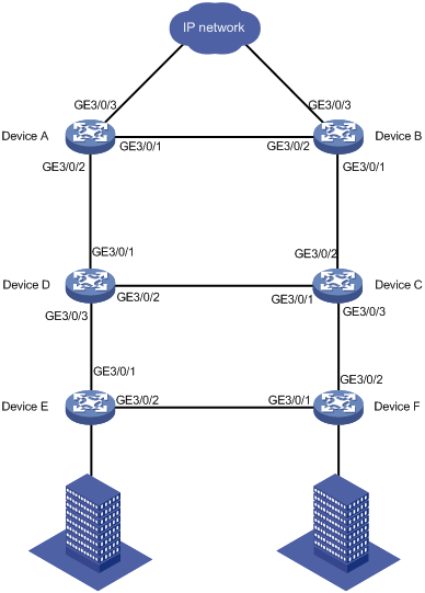
As shown in Figure 3, a ring-shaped access layer network is connected to a ring-shaped distribution layer network. Configure RRPP to implement the following requirements in the network:
· Eliminate loops and implement link recovery in the Layer 2 network.
· Implement link load balancing by forwarding voice traffic in VLAN 100 through VLAN 150 and video traffic in VLAN 151 through VLAN 200.
· Improve RRPP topology convergence speed by setting the physical state change suppression interval to 0 seconds for all Ethernet interfaces on the RRPP ring.
Analysis
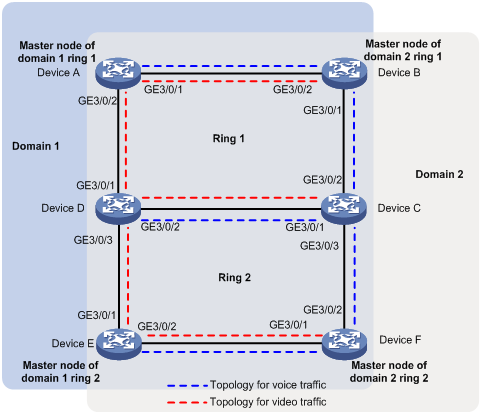
For voice and video traffic to be forwarded in different topologies, create two RRPP domains.
· In RRPP domain 1, specify VLAN 100 through VLAN 150 as protected VLANs. Specify Device A as the master node of primary ring 1, and Device E as the master node of subring 2.
· In RRPP domain 2, specify VLAN 151 through VLAN 200 as protected VLANs. Specify Device B as the master node of primary ring 1, and Device F as the master node of subring 2.
To implement load balancing for voice and video traffic, perform the following tasks:
· On Device A, specify GigabitEthernet 3/0/1 as the primary port, and GigabitEthernet 3/0/2 as the secondary port.
· On Device B, specify GigabitEthernet 3/0/2 as the primary port, and GigabitEthernet 3/0/1 as the secondary port.
· On Device E, specify GigabitEthernet 3/0/2 as the primary port, and GigabitEthernet 3/0/1 as the secondary port.
· On Device F, specify GigabitEthernet 3/0/1 as the primary port, and GigabitEthernet 3/0/2 as the secondary port.
Figure 4 Topologies for voice and video traffic
Restrictions and guidelines
When you configure intersecting rings, follow these restrictions and guidelines:
· When you configure fast detection in an RRPP domain, enable fast detection first on the edge node, and then on the assistant edge node. When you configure an edge node or assistant edge node, you must configure the primary ring before configuring the subrings.
· After you configure RRPP rings for an RRPP domain, you cannot delete or modify the primary control VLAN of the domain. You can only use the undo control-vlan command to delete a primary control VLAN.
· When you configure load balancing, you must configure different protected VLANs for different RRPP domains.
· Before you enable subrings on a device, you must enable the primary ring. Before you disable the primary ring on the device, you must disable all subrings.
· If a device carries multiple RRPP rings in an RRPP domain, it can only be an edge node or an assistant edge node on a subring.
· To prevent Hello packets of subrings from being looped on the primary ring, first enable the primary ring on its master node. Then enable the subrings on their respective master nodes.
Procedures
Configuring Device A
# Create VLANs 100 through 200.
<DeviceA> system-view
[DeviceA] vlan 100 to 200
# Map VLANs 100 through 150 to MSTI 1, and VLANs 151 through 200 to MSTI 2.
[DeviceA] stp region-configuration
[DeviceA-mst-region] instance 1 vlan 100 to 150
[DeviceA-mst-region] instance 2 vlan 151 to 200
# Activate the MST region configuration.
[DeviceA-mst-region] active region-configuration
[DeviceA-mst-region] quit
# Configure GigabitEthernet 3/0/1 as a trunk port.
[DeviceA] interface gigabitEthernet 3/0/1
[DeviceA-GigabitEthernet3/0/1] port link-type trunk
# Assign the port to VLANs 100 through 200, and remove it from VLAN 1.
[DeviceA-GigabitEthernet3/0/1] port trunk permit vlan 100 to 200
[DeviceA-GigabitEthernet3/0/1] undo port trunk permit vlan 1
# Set the physical state change suppression interval to 0 seconds on the port.
[DeviceA-GigabitEthernet3/0/1] link-delay 0 mode updown
# Disable the spanning tree feature on the port.
[DeviceA-GigabitEthernet3/0/1] undo stp enable
[DeviceA-GigabitEthernet3/0/1] quit
# Configure GigabitEthernet 3/0/2 in the same way GigabitEthernet 3/0/1 is configured.
[DeviceA] interface gigabitEthernet 3/0/2
[DeviceA-GigabitEthernet3/0/2] port link-type trunk
[DeviceA-GigabitEthernet3/0/2] port trunk permit vlan 100 to 200
[DeviceA-GigabitEthernet3/0/2] undo port trunk permit vlan 1
[DeviceA-GigabitEthernet3/0/2] link-delay 0 mode updown
[DeviceA-GigabitEthernet3/0/2] undo stp enable
[DeviceA-GigabitEthernet3/0/2] quit
# Create RRPP domain 1.
[DeviceA] rrpp domain 1
# Configure VLAN 1000 as the primary control VLAN of RRPP domain 1.
[DeviceA-rrpp-domain1] control-vlan 1000
# Configure the VLANs mapped to MSTI 1 as the protected VLANs of RRPP domain 1.
[DeviceA-rrpp-domain1] protected-vlan reference-instance 1
# Configure Device A as the master node of primary ring 1, with GigabitEthernet 3/0/1 as the primary port and GigabitEthernet 3/0/2 as the secondary port. Enable ring 1.
[DeviceA-rrpp-domain1] ring 1 node-mode master primary-port gigabitEthernet 3/0/1 secondary-port gigabitEthernet 3/0/2 level 0
[DeviceA-rrpp-domain1] ring 1 enable
[DeviceA-rrpp-domain1] quit
# Create RRPP domain 2.
[DeviceA] rrpp domain 2
# Configure VLAN 2000 as the primary control VLAN of RRPP domain 2.
[DeviceA-rrpp-domain2] control-vlan 2000
# Configure the VLANs mapped to MSTI 2 as the protected VLANs of RRPP domain 2.
[DeviceA-rrpp-domain2] protected-vlan reference-instance 2
# Configure Device A as the transit node of primary ring 1, with GigabitEthernet 3/0/1 as the primary port and GigabitEthernet 3/0/2 as the secondary port. Enable ring 1.
[DeviceA-rrpp-domain2] ring 1 node-mode transit primary-port gigabitEthernet 3/0/1 secondary-port gigabitEthernet 3/0/2 level 0
[DeviceA-rrpp-domain2] ring 1 enable
[DeviceA-rrpp-domain2] quit
# Enable RRPP.
[DeviceA] rrpp enable
Configuring Device B
# Create VLANs 100 through 200.
<DeviceB> system-view
[DeviceB] vlan 100 to 200
# Map VLANs 100 through 150 to MSTI 1, and VLANs 151 through 200 to MSTI 2.
[DeviceB] stp region-configuration
[DeviceB-mst-region] instance 1 vlan 100 to 150
[DeviceB-mst-region] instance 2 vlan 151 to 200
# Activate the MST region configuration.
[DeviceB-mst-region] active region-configuration
[DeviceB-mst-region] quit
# Configure GigabitEthernet 3/0/1 as a trunk port.
[DeviceB] interface gigabitEthernet 3/0/1
[DeviceB-GigabitEthernet3/0/1] port link-type trunk
# Assign the port to VLANs 100 through 200, and remove it from VLAN 1.
[DeviceB-GigabitEthernet3/0/1] port trunk permit vlan 100 to 200
[DeviceB-GigabitEthernet3/0/1] undo port trunk permit vlan 1
# Set the physical state change suppression interval to 0 seconds on the port.
[DeviceB-GigabitEthernet3/0/1] link-delay 0 mode updown
# Disable the spanning tree feature on the port.
[DeviceB-GigabitEthernet3/0/1] undo stp enable
[DeviceB-GigabitEthernet3/0/1] quit
# Configure GigabitEthernet 3/0/2 in the same way GigabitEthernet 3/0/1 is configured.
[DeviceB] interface gigabitEthernet 3/0/2
[DeviceB-GigabitEthernet3/0/2] port link-type trunk
[DeviceB-GigabitEthernet3/0/2] port trunk permit vlan 100 to 200
[DeviceB-GigabitEthernet3/0/2] undo port trunk permit vlan 1
[DeviceB-GigabitEthernet3/0/2] link-delay 0 mode updown
[DeviceB-GigabitEthernet3/0/2] undo stp enable
[DeviceB-GigabitEthernet3/0/2] quit
# Create RRPP domain 1.
[DeviceB] rrpp domain 1
# Configure VLAN 1000 as the primary control VLAN of RRPP domain 1.
[DeviceB-rrpp-domain1] control-vlan 1000
# Configure the VLANs mapped to MSTI 1 as the protected VLANs of RRPP domain 1.
[DeviceB-rrpp-domain1] protected-vlan reference-instance 1
# Configure Device B as the transit node of primary ring 1, with GigabitEthernet 3/0/2 as the primary port and GigabitEthernet 3/0/1 as the secondary port. Enable ring 1.
[DeviceB-rrpp-domain1] ring 1 node-mode transit primary-port gigabitEthernet 3/0/2 secondary-port GigabitEthernet 3/0/1 level 0
[DeviceB-rrpp-domain1] ring 1 enable
[DeviceB-rrpp-domain1] quit
# Create RRPP domain 2.
[DeviceB] rrpp domain 2
# Configure VLAN 2000 as the primary control VLAN of RRPP domain 2.
[DeviceB-rrpp-domain2] control-vlan 2000
# Configure the VLANs mapped to MSTI 2 as the protected VLANs of RRPP domain 2.
[DeviceB-rrpp-domain2] protected-vlan reference-instance 2
# Configure Device B as the master node of primary ring 1, with GigabitEthernet 3/0/2 as the primary port and GigabitEthernet 3/0/1 as the secondary port. Enable ring 1.
[DeviceB-rrpp-domain2] ring 1 node-mode master primary-port gigabitEthernet 3/0/2 secondary-port GigabitEthernet 3/0/1 level 0
[DeviceB-rrpp-domain2] ring 1 enable
[DeviceB-rrpp-domain2] quit
# Enable RRPP.
[DeviceB] rrpp enable
Configuring Device C
# Create VLANs 100 through 200.
<DeviceC> system-view
[DeviceC] vlan 100 to 200
# Map VLANs 100 through 150 to MSTI 1, and VLANs 151 through 200 to MSTI 2.
[DeviceC] stp region-configuration
[DeviceC-mst-region] instance 1 vlan 100 to 150
[DeviceC-mst-region] instance 2 vlan 151 to 200
# Activate the MST region configuration.
[DeviceC-mst-region] active region-configuration
[DeviceC-mst-region] quit
# Configure GigabitEthernet 3/0/1 as a trunk port.
[DeviceC] interface gigabitEthernet 3/0/1
[DeviceC-GigabitEthernet3/0/1] port link-type trunk
# Assign the port to VLANs 100 through 200, and remove it from VLAN 1.
[DeviceC-GigabitEthernet3/0/1] port trunk permit vlan 100 to 200
[DeviceC-GigabitEthernet3/0/1] undo port trunk permit vlan 1
# Set the physical state change suppression interval to 0 seconds on the port.
[DeviceC-GigabitEthernet3/0/1] link-delay 0 mode updown
# Disable the spanning tree feature on the port.
[DeviceC-GigabitEthernet3/0/1] undo stp enable
[DeviceC-GigabitEthernet3/0/1] quit
# Configure GigabitEthernet 3/0/2 in the same way GigabitEthernet 3/0/1 is configured.
[DeviceC] interface gigabitEthernet 3/0/2
[DeviceC-GigabitEthernet3/0/2] port link-type trunk
[DeviceC-GigabitEthernet3/0/2] port trunk permit vlan 100 to 200
[DeviceC-GigabitEthernet3/0/2] undo port trunk permit vlan 1
[DeviceC-GigabitEthernet3/0/2] link-delay 0 mode updown
[DeviceC-GigabitEthernet3/0/2] undo stp enable
[DeviceC-GigabitEthernet3/0/2] quit
# Configure GigabitEthernet 3/0/3 in the same way GigabitEthernet 3/0/1 is configured.
[DeviceC] interface gigabitEthernet 3/0/3
[DeviceC-GigabitEthernet3/0/3] port link-type trunk
[DeviceC-GigabitEthernet3/0/3] port trunk permit vlan 100 to 200
[DeviceC-GigabitEthernet3/0/3] undo port trunk permit vlan 1
[DeviceC-GigabitEthernet3/0/3] link-delay 0 mode updown
[DeviceC-GigabitEthernet3/0/3] undo stp enable
[DeviceC-GigabitEthernet3/0/3] quit
# Create RRPP domain 1.
[DeviceC] rrpp domain 1
# Configure VLAN 1000 as the primary control VLAN of RRPP domain 1.
[DeviceC-rrpp-domain1] control-vlan 1000
# Configure the VLANs mapped to MSTI 1 as the protected VLANs of RRPP domain 1.
[DeviceC-rrpp-domain1] protected-vlan reference-instance 1
# Configure Device C as the transit node of primary ring 1, with GigabitEthernet 3/0/1 as the primary port and GigabitEthernet 3/0/2 as the secondary port. Enable ring 1.
[DeviceC-rrpp-domain1] ring 1 node-mode transit primary-port gigabitEthernet 3/0/1 secondary-port GigabitEthernet 3/0/2 level 0
[DeviceC-rrpp-domain1] ring 1 enable
# Configure Device C as the edge node of subring 2, with GigabitEthernet 3/0/3 as the edge port. Enable ring 2.
[DeviceC-rrpp-domain1] ring 2 node-mode edge edge-port gigabitEthernet 3/0/3
[DeviceC-rrpp-domain1] ring 2 enable
[DeviceC-rrpp-domain1] quit
# Create RRPP domain 2.
[DeviceC] rrpp domain 2
# Configure VLAN 2000 as the primary control VLAN of RRPP domain 2.
[DeviceC-rrpp-domain2] control-vlan 2000
# Configure the VLANs mapped to MSTI 2 as the protected VLANs of RRPP domain 2.
[DeviceC-rrpp-domain2] protected-vlan reference-instance 2
# Configure Device C as the transit node of primary ring 1, with GigabitEthernet 3/0/1 as the primary port and GigabitEthernet 3/0/2 as the secondary port. Enable ring 1.
[DeviceC-rrpp-domain2] ring 1 node-mode transit primary-port gigabitEthernet 3/0/1 secondary-port gigabitEthernet 3/0/2 level 0
[DeviceC-rrpp-domain2] ring 1 enable
# Configure Device C as the edge node of subring 2, with GigabitEthernet 3/0/3 as the edge port. Enable ring 2.
[DeviceC-rrpp-domain2] ring 2 node-mode edge edge-port gigabitEthernet 3/0/3
[DeviceC-rrpp-domain2] ring 2 enable
[DeviceC-rrpp-domain2] quit
# Enable RRPP.
[DeviceC] rrpp enable
Configuring Device D
# Create VLANs 100 through 200.
<DeviceD> system-view
[DeviceD] vlan 100 to 200
# Map VLANs 100 through 150 to MSTI 1, and VLANs 151 through 200 to MSTI 2.
[DeviceD] stp region-configuration
[DeviceD-mst-region] instance 1 vlan 100 to 150
[DeviceD-mst-region] instance 2 vlan 151 to 200
# Activate the MST region configuration.
[DeviceD-mst-region] active region-configuration
[DeviceD-mst-region] quit
# Configure GigabitEthernet 3/0/1 as a trunk port.
[DeviceD] interface gigabitEthernet 3/0/1
[DeviceD-GigabitEthernet3/0/1] port link-type trunk
# Assign the port to VLANs 100 through 200, and remove it from VLAN 1.
[DeviceD-GigabitEthernet3/0/1] port trunk permit vlan 100 to 200
[DeviceD-GigabitEthernet3/0/1] undo port trunk permit vlan 1
# Set the physical state change suppression interval to 0 seconds on the port.
[DeviceD-GigabitEthernet3/0/1] link-delay 0 mode updown
# Disable the spanning tree feature on the port.
[DeviceD-GigabitEthernet3/0/1] undo stp enable
[DeviceD-GigabitEthernet3/0/1] quit
# Configure GigabitEthernet 3/0/2 in the same way GigabitEthernet 3/0/1 is configured.
[DeviceD] interface gigabitEthernet 3/0/2
[DeviceD-GigabitEthernet3/0/2] port link-type trunk
[DeviceD-GigabitEthernet3/0/2] port trunk permit vlan 100 to 200
[DeviceD-GigabitEthernet3/0/2] undo port trunk permit vlan 1
[DeviceD-GigabitEthernet3/0/2] link-delay 0 mode updown
[DeviceD-GigabitEthernet3/0/2] undo stp enable
[DeviceD-GigabitEthernet3/0/2] quit
# Configure GigabitEthernet 3/0/3 in the same way GigabitEthernet 3/0/1 is configured.
[DeviceD] interface gigabitEthernet 3/0/3
[DeviceD-GigabitEthernet3/0/3] port link-type trunk
[DeviceD-GigabitEthernet3/0/3] port trunk permit vlan 100 to 200
[DeviceD-GigabitEthernet3/0/3] undo port trunk permit vlan 1
[DeviceD-GigabitEthernet3/0/3] link-delay 0 mode updown
[DeviceD-GigabitEthernet3/0/3] undo stp enable
[DeviceD-GigabitEthernet3/0/3] quit
# Create RRPP domain 1.
[DeviceD] rrpp domain 1
# Configure VLAN 1000 as the primary control VLAN of RRPP domain 1.
[DeviceD-rrpp-domain1] control-vlan 1000
# Configure the VLANs mapped to MSTI 1 as the protected VLANs of RRPP domain 1.
[DeviceD-rrpp-domain1] protected-vlan reference-instance 1
# Configure Device D as the transit node of primary ring 1, with GigabitEthernet 3/0/1 as the primary port and GigabitEthernet 3/0/2 as the secondary port. Enable ring 1.
[DeviceD-rrpp-domain1] ring 1 node-mode transit primary-port gigabitEthernet 3/0/1 secondary-port GigabitEthernet 3/0/2 level 0
[DeviceD-rrpp-domain1] ring 1 enable
# Configure Device D as the assistant edge node of subring 2, with GigabitEthernet 3/0/3 as the edge port. Enable ring 2.
[DeviceD-rrpp-domain1] ring 2 node-mode assistant-edge edge-port gigabitEthernet 3/0/3
[DeviceD-rrpp-domain1] ring 2 enable
[DeviceD-rrpp-domain1] quit
# Create RRPP domain 2.
[DeviceD] rrpp domain 2
# Configure VLAN 2000 as the primary control VLAN of RRPP domain 2.
[DeviceD-rrpp-domain2] control-vlan 2000
# Configure the VLANs mapped to MSTI 2 as the protected VLANs of RRPP domain 2.
[DeviceD-rrpp-domain2] protected-vlan reference-instance 2
# Configure Device D as the transit node of primary ring 1, with GigabitEthernet 3/0/1 as the primary port and GigabitEthernet 3/0/2 as the secondary port. Enable ring 1.
[DeviceD-rrpp-domain2] ring 1 node-mode transit primary-port gigabitEthernet 3/0/1 secondary-port gigabitEthernet 3/0/2 level 0
[DeviceD-rrpp-domain2] ring 1 enable
# Configure Device D as the assistant edge node of subring 2, with GigabitEthernet 3/0/3 as the edge port. Enable ring 2.
[DeviceD-rrpp-domain2] ring 2 node-mode assistant-edge edge-port gigabitEthernet 3/0/3
[DeviceD-rrpp-domain2] ring 2 enable
[DeviceD-rrpp-domain2] quit
# Enable RRPP.
[DeviceD] rrpp enable
Configuring Device E
# Create VLANs 100 through 200.
<DeviceE> system-view
[DeviceE] vlan 100 to 200
# Map VLANs 100 through 150 to MSTI 1, and VLANs 151 through 200 to MSTI 2.
[DeviceE] stp region-configuration
[DeviceE-mst-region] instance 1 vlan 100 to 150
[DeviceE-mst-region] instance 2 vlan 151 to 200
# Activate the MST region configuration.
[DeviceE-mst-region] active region-configuration
[DeviceE-mst-region] quit
# Configure GigabitEthernet 3/0/1 as a trunk port.
[DeviceE] interface gigabitEthernet 3/0/1
[DeviceE-GigabitEthernet3/0/1] port link-type trunk
# Assign the port to VLANs 100 through 200, and remove it from VLAN 1.
[DeviceE-GigabitEthernet3/0/1] port trunk permit vlan 100 to 200
[DeviceE-GigabitEthernet3/0/1] undo port trunk permit vlan 1
# Set the physical state change suppression interval to 0 seconds on the port.
[DeviceE-GigabitEthernet3/0/1] link-delay 0 mode updown
# Disable the spanning tree feature on the port.
[DeviceE-GigabitEthernet3/0/1] undo stp enable
[DeviceE-GigabitEthernet3/0/1] quit
# Configure GigabitEthernet 3/0/2 in the same way GigabitEthernet 3/0/1 is configured.
[DeviceE] interface gigabitEthernet 3/0/2
[DeviceE-GigabitEthernet3/0/2] port link-type trunk
[DeviceE-GigabitEthernet3/0/2] port trunk permit vlan 100 to 200
[DeviceE-GigabitEthernet3/0/2] undo port trunk permit vlan 1
[DeviceE-GigabitEthernet3/0/2] link-delay 0 mode updown
[DeviceE-GigabitEthernet3/0/2] undo stp enable
[DeviceE-GigabitEthernet3/0/2] quit
# Create RRPP domain 1.
[DeviceE] rrpp domain 1
# Configure VLAN 1000 as the primary control VLAN of RRPP domain 1.
[DeviceE-rrpp-domain1] control-vlan 1000
# Configure the VLANs mapped to MSTI 1 as the protected VLANs of RRPP domain 1.
[DeviceE-rrpp-domain1] protected-vlan reference-instance 1
# Configure Device E as the master node of subring 2, with GigabitEthernet 3/0/2 as the primary port and GigabitEthernet 3/0/1 as the secondary port. Enable ring 2.
[DeviceE-rrpp-domain1] ring 2 node-mode master primary-port gigabitEthernet 3/0/2 secondary-port gigabitEthernet 3/0/1 level 1
[DeviceE-rrpp-domain1] ring 2 enable
[DeviceE-rrpp-domain1] quit
# Create RRPP domain 2.
[DeviceE] rrpp domain 2
# Configure VLAN 2000 as the primary control VLAN of RRPP domain 2.
[DeviceE-rrpp-domain2] control-vlan 2000
# Configure the VLANs mapped to MSTI 2 as the protected VLANs of RRPP domain 2.
[DeviceE-rrpp-domain2] protected-vlan reference-instance 2
# Configure Device E as the transit node of subring 2, with GigabitEthernet 3/0/2 as the primary port and GigabitEthernet 3/0/1 as the secondary port. Enable ring 2.
[DeviceE-rrpp-domain2] ring 2 node-mode transit primary-port gigabitEthernet 3/0/2 secondary-port gigabitEthernet 3/0/1 level 1
[DeviceE-rrpp-domain2] ring 2 enable
[DeviceE-rrpp-domain2] quit
# Enable RRPP.
[DeviceE] rrpp enable
Configuring Device F
# Create VLANs 100 through 200.
<DeviceF> system-view
[DeviceF] vlan 100 to 200
# Map VLANs 100 through 150 to MSTI 1, and VLANs 151 through 200 to MSTI 2.
[DeviceF] stp region-configuration
[DeviceF-mst-region] instance 1 vlan 100 to 150
[DeviceF-mst-region] instance 2 vlan 151 to 200
# Activate the MST region configuration.
[DeviceF-mst-region] active region-configuration
[DeviceF-mst-region] quit
# Configure GigabitEthernet 3/0/1 as a trunk port.
[DeviceF] interface gigabitEthernet 3/0/1
[DeviceF-GigabitEthernet3/0/1] port link-type trunk
# Assign the port to VLANs 100 through 200, and remove it from VLAN 1.
[DeviceF-GigabitEthernet3/0/1] port trunk permit vlan 100 to 200
[DeviceF-GigabitEthernet3/0/1] undo port trunk permit vlan 1
# Set the physical state change suppression interval to 0 seconds on the port.
[DeviceF-GigabitEthernet3/0/1] link-delay 0 mode updown
# Disable the spanning tree feature on the port.
[DeviceF-GigabitEthernet3/0/1] undo stp enable
[DeviceF-GigabitEthernet3/0/1] quit
# Configure GigabitEthernet 3/0/2 in the same way GigabitEthernet 3/0/1 is configured.
[DeviceF] interface gigabitEthernet 3/0/2
[DeviceF-GigabitEthernet3/0/2] port link-type trunk
[DeviceF-GigabitEthernet3/0/2] port trunk permit vlan 100 to 200
[DeviceF-GigabitEthernet3/0/2] undo port trunk permit vlan 1
[DeviceF-GigabitEthernet3/0/2] link-delay 0 mode updown
[DeviceF-GigabitEthernet3/0/2] undo stp enable
[DeviceF-GigabitEthernet3/0/2] quit
# Create RRPP domain 1.
[DeviceF] rrpp domain 1
# Configure VLAN 1000 as the primary control VLAN of RRPP domain 1.
[DeviceF-rrpp-domain1] control-vlan 1000
# Configure the VLANs mapped to MSTI 1 as the protected VLANs of RRPP domain 1.
[DeviceF-rrpp-domain1] protected-vlan reference-instance 1
# Configure Device F as the transit node of subring 2, with GigabitEthernet 3/0/1 as the primary port and GigabitEthernet 3/0/2 as the secondary port. Enable ring 2.
[DeviceF-rrpp-domain1] ring 2 node-mode transit primary-port gigabitEthernet 3/0/1 secondary-port gigabitEthernet 3/0/2 level 1
[DeviceF-rrpp-domain1] ring 2 enable
[DeviceF-rrpp-domain1] quit
# Create RRPP domain 2.
[DeviceF] rrpp domain 2
# Configure VLAN 2000 as the primary control VLAN of RRPP domain 2.
[DeviceF-rrpp-domain2] control-vlan 2000
# Configure the VLANs mapped to MSTI 2 as the protected VLANs of RRPP domain 2.
[DeviceF-rrpp-domain2] protected-vlan reference-instance 2
# Configure Device F as the master node of subring 2, with GigabitEthernet 3/0/1 as the primary port and GigabitEthernet 3/0/2 as the secondary port. Enable ring 2.
[DeviceF-rrpp-domain2] ring 2 node-mode master primary-port gigabitEthernet 3/0/1 secondary-port gigabitEthernet 3/0/2 level 1
[DeviceF-rrpp-domain2] ring 2 enable
[DeviceF-rrpp-domain2] quit
# Enable RRPP.
[DeviceF] rrpp enable
Verifying the configuration
# View detailed information about RRPP domain 1 on Device A.
[DeviceA] display rrpp verbose domain 1
Domain ID : 1
Control VLAN : Primary 1000, Secondary 1001
Protected VLAN: Reference instance 1
Hello timer : 1 seconds, Fail timer: 3 seconds
Fast detection status: Disabled
Fast-Hello timer: 20 ms, Fast-Fail timer: 60 ms
Fast-Edge-Hello timer: 10 ms, Fast-Edge-Fail timer: 30 ms
Ring ID : 1
Ring Level : 0
Node Mode : Master
Ring State : Complete
Enable Status : Yes Active Status: Yes
Primary port : GE3/0/1 Port status: UP
Secondary port: GE3/0/2 Port status: BLOCK
The output shows the following information:
· Device A is the master node of primary ring 1 in RRPP domain 1.
· The primary ring state of RRPP domain 1 is complete.
· The primary port is up, and the secondary port is blocked.
# View detailed information about RRPP domain 2 on Device A.
[DeviceA] display rrpp verbose domain 2
Domain ID : 2
Control VLAN : Primary 2000, Secondary 2001
Protected VLAN: Reference instance 2
Hello timer : 1 seconds, Fail timer: 3 seconds
Fast detection status: Disabled
Fast-Hello timer: 20 ms, Fast-Fail timer: 60 ms
Fast-Edge-Hello timer: 10 ms, Fast-Edge-Fail timer: 30 ms
Ring ID : 1
Ring Level : 0
Node Mode : Transit
Ring State : -
Enable Status : Yes Active Status: Yes
Primary port : GE3/0/1 Port status: UP
Secondary port: GE3/0/2 Port status: UP
The output shows the following information:
· Device A is the transit node of primary ring 1 in RRPP domain 2.
· The primary and secondary ports are up.
# View detailed information about RRPP domain 1 on Device B.
[DeviceB] display rrpp verbose domain 1
Domain ID : 1
Control VLAN : Primary 1000, Secondary 1001
Protected VLAN: Reference instance 1
Hello timer : 1 seconds, Fail timer: 3 seconds
Fast detection status: Disabled
Fast-Hello timer: 20 ms, Fast-Fail timer: 60 ms
Fast-Edge-Hello timer: 10 ms, Fast-Edge-Fail timer: 30 ms
Ring ID : 1
Ring Level : 0
Node Mode : Transit
Ring State : -
Enable Status : Yes Active Status: Yes
Primary port : GE3/0/2 Port status: UP
Secondary port: GE3/0/1 Port status: UP
The output shows the following information:
· Device B is the transit node of primary ring 1 in RRPP domain 1.
· The primary and secondary ports are up.
# View detailed information about RRPP domain 2 on Device B.
[DeviceB] display rrpp verbose domain 2
Domain ID : 2
Control VLAN : Primary 2000, Secondary 2001
Protected VLAN: Reference instance 2
Hello timer : 1 seconds, Fail timer: 3 seconds
Fast detection status: Disabled
Fast-Hello timer: 20 ms, Fast-Fail timer: 60 ms
Fast-Edge-Hello timer: 10 ms, Fast-Edge-Fail timer: 30 ms
Ring ID : 1
Ring Level : 0
Node Mode : Master
Ring State : Complete
Enable Status : Yes Active Status: Yes
Primary port : GE3/0/2 Port status: UP
Secondary port: GE3/0/1 Port status: BLOCK
The output shows the following information:
· Device B is the master node of primary ring 1 in RRPP domain 2.
· The primary ring state of RRPP domain 2 is complete.
· The primary port is up, and the secondary port is blocked.
# View detailed information about RRPP domain 1 on Device C.
[DeviceC] display rrpp verbose domain 1
Domain ID : 1
Control VLAN : Primary 1000, Secondary 1001
Protected VLAN: Reference instance 1
Hello timer : 1 seconds, Fail timer: 3 seconds
Fast detection status: Disabled
Fast-Hello timer: 20 ms, Fast-Fail timer: 60 ms
Fast-Edge-Hello timer: 10 ms, Fast-Edge-Fail timer: 30 ms
Ring ID : 1
Ring Level : 0
Node Mode : Transit
Ring State : -
Enable Status : Yes Active Status: Yes
Primary port : GE3/0/1 Port status: UP
Secondary port: GE3/0/2 Port status: UP
Ring ID : 2
Ring Level : 1
Node Mode : Edge
Ring State : -
Enable Status : Yes Active Status: Yes
Common port : GE3/0/1 Port status: UP
GE3/0/2 Port status: UP
Edge port : GE3/0/3 Port status: UP
The output shows the following information:
· Device C is the transit node of primary ring 1 and edge node of subring 2 in RRPP domain 1.
· The primary and secondary ports are up.
# View detailed information about RRPP domain 2 on Device C.
[DeviceC] display rrpp verbose domain 2
Domain ID : 2
Control VLAN : Primary 2000, Secondary 2001
Protected VLAN: Reference instance 2
Hello timer : 1 seconds, Fail timer: 3 seconds
Fast detection status: Disabled
Fast-Hello timer: 20 ms, Fast-Fail timer: 60 ms
Fast-Edge-Hello timer: 10 ms, Fast-Edge-Fail timer: 30 ms
Ring ID : 1
Ring Level : 0
Node Mode : Transit
Ring State : -
Enable Status : Yes Active Status: Yes
Primary port : GE3/0/1 Port status: UP
Secondary port: GE3/0/2 Port status: UP
Ring ID : 2
Ring Level : 1
Node Mode : Edge
Ring State : -
Enable Status : Yes Active Status: Yes
Common port : GE3/0/1 Port status: UP
GE3/0/2 Port status: UP
Edge port : GE3/0/3 Port status: UP
The output shows the following information:
· Device C is the transit node of primary ring 1 and edge node of subring 2 in RRPP domain 2.
· The primary and secondary ports are up.
# View detailed information about RRPP domain 1 on Device D.
[DeviceD] display rrpp verbose domain 1
Domain ID : 1
Control VLAN : Primary 1000, Secondary 1001
Protected VLAN: Reference instance 1
Hello timer : 1 seconds, Fail timer: 3 seconds
Fast detection status: Disabled
Fast-Hello timer: 20 ms, Fast-Fail timer: 60 ms
Fast-Edge-Hello timer: 10 ms, Fast-Edge-Fail timer: 30 ms
Ring ID : 1
Ring Level : 0
Node Mode : Transit
Ring State : -
Enable Status : Yes Active Status: Yes
Primary port : GE3/0/1 Port status: UP
Secondary port: GE3/0/2 Port status: UP
Ring ID : 2
Ring Level : 1
Node Mode : Assistant-edge
Ring State : -
Enable Status : Yes Active Status: Yes
Common port : GE3/0/1 Port status: UP
GE3/0/2 Port status: UP
Edge port : GE3/0/3 Port status: UP
The output shows the following information:
· Device D is the transit node of primary ring 1 and assistant edge node of subring 2 in RRPP domain 1.
· The primary and secondary ports are up.
# View detailed information about RRPP domain 2 on Device D.
[DeviceD] display rrpp verbose domain 2
Domain ID : 2
Control VLAN : Primary 2000, Secondary 2001
Protected VLAN: Reference instance 2
Hello timer : 1 seconds, Fail timer: 3 seconds
Fast detection status: Disabled
Fast-Hello timer: 20 ms, Fast-Fail timer: 60 ms
Fast-Edge-Hello timer: 10 ms, Fast-Edge-Fail timer: 30 ms
Ring ID : 1
Ring Level : 0
Node Mode : Transit
Ring State : -
Enable Status : Yes Active Status: Yes
Primary port : GE3/0/1 Port status: UP
Secondary port: GE3/0/2 Port status: UP
Ring ID : 2
Ring Level : 1
Node Mode : Assistant-edge
Ring State : -
Enable Status : Yes Active Status: Yes
Common port : GE3/0/1 Port status: UP
GE3/0/2 Port status: UP
Edge port : GE3/0/3 Port status: UP
The output shows the following information:
· Device D is the transit node of primary ring 1 and assistant edge node of subring 2 in RRPP domain 2.
· The primary and secondary ports are up.
# View detailed information about RRPP domain 1 on Device E.
[DeviceE] display rrpp verbose domain 1
Domain ID : 1
Control VLAN : Primary 1000, Secondary 1001
Protected VLAN: Reference instance 1
Hello timer : 1 seconds, Fail timer: 3 seconds
Fast detection status: Disabled
Fast-Hello timer: 20 ms, Fast-Fail timer: 60 ms
Fast-Edge-Hello timer: 10 ms, Fast-Edge-Fail timer: 30 ms
Ring ID : 2
Ring Level : 1
Node Mode : Master
Ring State : Complete
Enable Status : Yes Active Status: Yes
Primary port : GE3/0/2 Port status: UP
Secondary port: GE3/0/1 Port status: BLOCK
The output shows the following information:
· Device E is the master node of subring 2 in RRPP domain 1.
· The subring state of RRPP domain 1 is complete.
· The primary port is up, and the secondary port is blocked.
# View detailed information about RRPP domain 2 on Device E.
[DeviceE] display rrpp verbose domain 2
Domain ID : 2
Control VLAN : Primary 2000, Secondary 2001
Protected VLAN: Reference instance 2
Hello timer : 1 seconds, Fail timer: 3 seconds
Fast detection status: Disabled
Fast-Hello timer: 20 ms, Fast-Fail timer: 60 ms
Fast-Edge-Hello timer: 10 ms, Fast-Edge-Fail timer: 30 ms
Ring ID : 2
Ring Level : 1
Node Mode : Transit
Ring State : -
Enable Status : Yes Active Status: Yes
Primary port : GE3/0/2 Port status: UP
Secondary port: GE3/0/1 Port status: UP
The output shows the following information:
· Device E is the transit node of subring 2 in RRPP domain 2.
· The primary and secondary ports are up.
# View detailed information about RRPP domain 1 on Device F.
[DeviceF] display rrpp verbose domain 1
Domain ID : 1
Control VLAN : Primary 1000, Secondary 1001
Protected VLAN: Reference instance 1
Hello timer : 1 seconds, Fail timer: 3 seconds
Fast detection status: Disabled
Fast-Hello timer: 20 ms, Fast-Fail timer: 60 ms
Fast-Edge-Hello timer: 10 ms, Fast-Edge-Fail timer: 30 ms
Ring ID : 2
Ring Level : 1
Node Mode : Transit
Ring State : -
Enable Status : Yes Active Status: Yes
Primary port : GE3/0/1 Port status: UP
Secondary port: GE3/0/2 Port status: UP
The output shows the following information:
· Device F is the transit node of subring 2 in RRPP domain 1.
· The primary and secondary ports are up.
# View detailed information about RRPP domain 2 on Device F.
[DeviceF] display rrpp verbose domain 2
Domain ID : 2
Control VLAN : Primary 2000, Secondary 2001
Protected VLAN: Reference instance 2
Hello timer : 1 seconds, Fail timer: 3 seconds
Fast detection status: Disabled
Fast-Hello timer: 20 ms, Fast-Fail timer: 60 ms
Fast-Edge-Hello timer: 10 ms, Fast-Edge-Fail timer: 30 ms
Ring ID : 2
Ring Level : 1
Node Mode : Master
Ring State : Complete
Enable Status : Yes Active Status: Yes
Primary port : GE3/0/1 Port status: UP
Secondary port: GE3/0/2 Port status: BLOCK
The output shows the following information:
· Device F is the master node of subring 2 in RRPP domain 2.
· The subring state of RRPP domain 2 is complete.
· The primary port is up, and the secondary port is blocked.
Configuration files
· Device A:
#
sysname DeviceA
#
vlan 1
#
vlan 100 to 200
#
stp region-configuration
instance 1 vlan 100 to 150
instance 2 vlan 151 to 200
active region-configuration
#
interface GigabitEthernet3/0/1
port link-mode bridge
port link-type trunk
undo port trunk permit vlan 1
port trunk permit vlan 100 to 200
link-delay 0 mode updown
undo stp enable
#
interface GigabitEthernet3/0/2
port link-mode bridge
port link-type trunk
undo port trunk permit vlan 1
port trunk permit vlan 100 to 200
link-delay 0 mode updown
undo stp enable
#
rrpp domain 1
control-vlan 1000
protected-vlan reference-instance 1
ring 1 node-mode master primary-port GigabitEthernet3/0/1 secondary-port GigabitEthernet3/0/2 level 0
ring 1 enable
#
rrpp domain 2
control-vlan 2000
protected-vlan reference-instance 2
ring 1 node-mode transit primary-port GigabitEthernet3/0/1 secondary-port GigabitEthernet3/0/2 level 0
ring 1 enable
#
rrpp enable
#
· Device B:
#
sysname DeviceB
#
vlan 1
#
vlan 100 to 200
#
stp region-configuration
instance 1 vlan 100 to 150
instance 2 vlan 151 to 200
active region-configuration
#
interface GigabitEthernet3/0/1
port link-mode bridge
port link-type trunk
undo port trunk permit vlan 1
port trunk permit vlan 100 to 200
link-delay 0 mode updown
undo stp enable
#
interface GigabitEthernet3/0/2
port link-mode bridge
port link-type trunk
undo port trunk permit vlan 1
port trunk permit vlan 100 to 200
link-delay 0 mode updown
undo stp enable
#
rrpp domain 1
control-vlan 1000
protected-vlan reference-instance 1
ring 1 node-mode transit primary-port GigabitEthernet3/0/2 secondary-port GigabitEthernet3/0/1 level 0
ring 1 enable
#
rrpp domain 2
control-vlan 2000
protected-vlan reference-instance 2
ring 1 node-mode master primary-port GigabitEthernet3/0/2 secondary-port GigabitEthernet3/0/1 level 0
ring 1 enable
#
rrpp enable
#
· Device C:
#
sysname DeviceC
#
vlan 1
#
vlan 100 to 200
#
stp region-configuration
instance 1 vlan 100 to 150
instance 2 vlan 151 to 200
active region-configuration
#
interface GigabitEthernet3/0/1
port link-mode bridge
port link-type trunk
undo port trunk permit vlan 1
port trunk permit vlan 100 to 200
link-delay 0 mode updown
undo stp enable
#
interface GigabitEthernet3/0/2
port link-mode bridge
port link-type trunk
undo port trunk permit vlan 1
port trunk permit vlan 100 to 200
link-delay 0 mode updown
undo stp enable
#
interface GigabitEthernet3/0/3
port link-mode bridge
port link-type trunk
undo port trunk permit vlan 1
port trunk permit vlan 100 to 200
link-delay 0 mode updown
undo stp enable
#
rrpp domain 1
control-vlan 1000
protected-vlan reference-instance 1
ring 1 node-mode transit primary-port GigabitEthernet3/0/1 secondary-port GigabitEthernet3/0/2 level 0
ring 1 enable
ring 2 node-mode edge edge-port GigabitEthernet 3/0/3
ring 2 enable
#
rrpp domain 2
control-vlan 2000
protected-vlan reference-instance 2
ring 1 node-mode transit primary-port GigabitEthernet3/0/1 secondary-port GigabitEthernet3/0/2 level 0
ring 1 enable
ring 2 node-mode edge edge-port GigabitEthernet 3/0/3
ring 2 enable
#
rrpp enable
#
· Device D:
#
sysname DeviceD
#
vlan 1
#
vlan 100 to 200
#
stp region-configuration
instance 1 vlan 100 to 150
instance 2 vlan 151 to 200
active region-configuration
#
interface GigabitEthernet3/0/1
port link-mode bridge
port link-type trunk
undo port trunk permit vlan 1
port trunk permit vlan 100 to 200
link-delay 0 mode updown
undo stp enable
#
interface GigabitEthernet3/0/2
port link-mode bridge
port link-type trunk
undo port trunk permit vlan 1
port trunk permit vlan 100 to 200
link-delay 0 mode updown
undo stp enable
#
interface GigabitEthernet3/0/3
port link-mode bridge
port link-type trunk
undo port trunk permit vlan 1
port trunk permit vlan 100 to 200
link-delay 0 mode updown
undo stp enable
#
rrpp domain 1
control-vlan 1000
protected-vlan reference-instance 1
ring 1 node-mode transit primary-port GigabitEthernet3/0/1 secondary-port GigabitEthernet3/0/2 level 0
ring 1 enable
ring 2 node-mode assistant-edge edge-port GigabitEthernet 3/0/3
ring 2 enable
#
rrpp domain 2
control-vlan 2000
protected-vlan reference-instance 2
ring 1 node-mode transit primary-port GigabitEthernet3/0/1 secondary-port GigabitEthernet3/0/2 level 0
ring 1 enable
ring 2 node-mode assistant-edge edge-port GigabitEthernet 3/0/3
ring 2 enable
#
rrpp enable
#
· Device E:
#
sysname DeviceE
#
vlan 1
#
vlan 100 to 200
#
stp region-configuration
instance 1 vlan 100 to 150
instance 2 vlan 151 to 200
active region-configuration
#
interface GigabitEthernet3/0/1
port link-mode bridge
port link-type trunk
undo port trunk permit vlan 1
port trunk permit vlan 100 to 200
link-delay 0 mode updown
undo stp enable
#
interface GigabitEthernet3/0/2
port link-mode bridge
port link-type trunk
undo port trunk permit vlan 1
port trunk permit vlan 100 to 200
link-delay 0 mode updown
undo stp enable
#
rrpp domain 1
control-vlan 1000
protected-vlan reference-instance 1
ring 2 node-mode master primary-port GigabitEthernet3/0/2 secondary-port GigabitEthernet3/0/1 level 1
ring 2 enable
#
rrpp domain 2
control-vlan 2000
protected-vlan reference-instance 2
ring 2 node-mode transit primary-port GigabitEthernet3/0/2 secondary-port GigabitEthernet3/0/1 level 1
ring 2 enable
#
rrpp enable
#
· Device F:
#
sysname DeviceF
#
vlan 1
#
vlan 100 to 200
#
stp region-configuration
instance 1 vlan 100 to 150
instance 2 vlan 151 to 200
active region-configuration
#
interface GigabitEthernet3/0/1
port link-mode bridge
port link-type trunk
undo port trunk permit vlan 1
port trunk permit vlan 100 to 200
link-delay 0 mode updown
undo stp enable
#
interface GigabitEthernet3/0/2
port link-mode bridge
port link-type trunk
undo port trunk permit vlan 1
port trunk permit vlan 100 to 200
link-delay 0 mode updown
undo stp enable
#
rrpp domain 1
control-vlan 1000
protected-vlan reference-instance 1
ring 2 node-mode transit primary-port GigabitEthernet3/0/1 secondary-port GigabitEthernet3/0/2 level 1
ring 2 enable
#
rrpp domain 2
control-vlan 2000
protected-vlan reference-instance 2
ring 2 node-mode master primary-port GigabitEthernet3/0/1 secondary-port GigabitEthernet3/0/2 level 1
ring 2 enable
#
rrpp enable
#
Example: Configuring dual-homed intersecting rings
Network configuration
As shown in Figure 5, a ring-shaped campus network is connected to a ring-shaped distribution layer network through an access layer device. Configure RRPP to implement the following requirements in the network:
· Eliminate loops and implement link recovery in the Layer 2 network.
· Implement link load balancing by forwarding voice traffic in VLAN 100 through VLAN 150 and video traffic in VLAN 151 through VLAN 200.
· Improve RRPP topology convergence speed by setting the physical state change suppression interval to 0 seconds for all Ethernet interfaces on the RRPP ring.
· Reduce the number of Edge-Hello packets.
Analysis
For voice and video traffic to be forwarded in different topologies, create four RRPP domains.
· In RRPP domain 1 and domain 4, specify VLAN 100 through VLAN 150 as protected VLANs, and configure the node roles as follows:
¡ Specify Device A as the master node of primary ring 1.
¡ Specify Device E as the master node of subring 2.
¡ Specify Device F as the master node of subring 3.
¡ Specify Device H as the master node of subring 4.
· In RRPP domain 2 and domain 3, specify VLAN 151 through VLAN 200 as protected VLANs, and configure the node roles as follows:
¡ Specify Device B as the master node of primary ring 1.
¡ Specify Device E as the master node of subring 2.
¡ Specify Device F as the master node of subring 3.
¡ Specify Device H as the master node of subring 4.
To implement load balancing for voice and video traffic, perform the following tasks:
· On Device A, specify GigabitEthernet 3/0/1 as the primary port, and GigabitEthernet 3/0/2 as the secondary port.
· On Device B, specify GigabitEthernet 3/0/2 as the primary port, and GigabitEthernet 3/0/1 as the secondary port.
· On Device E, specify GigabitEthernet 3/0/1 as the secondary port in RRPP domain 1 and primary port in RRPP domain 2. Specify GigabitEthernet 3/0/2 as the primary port in RRPP domain 1 and secondary port in RRPP domain 2.
· On Device F, specify GigabitEthernet 3/0/1 as the secondary port in RRPP domain 1 and primary port in RRPP domain 2. Specify GigabitEthernet 3/0/2 as the primary port in RRPP domain 1 and secondary port in RRPP domain 2.
· On Device H, specify GigabitEthernet 3/0/1 as the secondary port in RRPP domain 3 and primary port in RRPP domain 4. Specify GigabitEthernet 3/0/2 as the primary port in RRPP domain 3 and secondary port in RRPP domain 4.
To reduce the number of Edge-Hello packets, add ring 2 and ring 3 in RRPP domain 1 and 2 to a ring group.
Figure 6 Topologies for voice and video traffic
Restrictions and guidelines
When you configure dual-homed intersecting rings, follow these restrictions and guidelines:
· To avoid temporary loops when the primary ring fails, make sure the difference between the Fail timer values on the master node of the subring and primary ring is greater than twice the Hello timer value on the master node of the subring.
· When you configure fast detection in an RRPP domain, enable fast detection first on the edge node, and then on the assistant edge node. When you configure an edge node or assistant edge node, you must configure the primary ring before configuring the subrings.
· After you configure RRPP rings for an RRPP domain, you cannot delete or modify the primary control VLAN of the domain. You can only use the undo control-vlan command to delete a primary control VLAN.
· When you configure load balancing, you must configure different protected VLANs for different RRPP domains.
· Before you enable subrings on a device, you must enable the primary ring. Before you disable the primary ring on the device, you must disable all subrings.
· If a device carries multiple RRPP rings in an RRPP domain, it can only be an edge node or an assistant edge node on a subring.
· To prevent Hello packets of subrings from being looped on the primary ring, first enable the primary ring on its master node. Then enable the subrings on their respective master nodes.
· Make sure all subrings in an RRPP ring group have the same SRPTs. You can assign a subring to only one RRPP ring group. For the RRPP ring group to operate correctly, the RRPP ring groups configured on the edge node and the assistant edge node must contain the same subrings.
· Make sure the RRPP ring groups on the edge node and the assistant edge node have the same configurations and activation status.
Procedures
Configuring Device A
# Create VLANs 100 through 200.
<DeviceA> system-view
[DeviceA] vlan 100 to 200
# Map VLANs 100 through 150 to MSTI 1, and VLANs 151 through 200 to MSTI 2.
[DeviceA] stp region-configuration
[DeviceA-mst-region] instance 1 vlan 100 to 150
[DeviceA-mst-region] instance 2 vlan 151 to 200
# Activate the MST region configuration.
[DeviceA-mst-region] active region-configuration
[DeviceA-mst-region] quit
# Configure GigabitEthernet 3/0/1 as a trunk port.
[DeviceA] interface gigabitEthernet 3/0/1
[DeviceA-GigabitEthernet3/0/1] port link-type trunk
# Assign the port to VLANs 100 through 200, and remove it from VLAN 1.
[DeviceA-GigabitEthernet3/0/1] port trunk permit vlan 100 to 200
[DeviceA-GigabitEthernet3/0/1] undo port trunk permit vlan 1
# Set the physical state change suppression interval to 0 seconds on the port.
[DeviceA-GigabitEthernet3/0/1] link-delay 0 mode updown
# Disable the spanning tree feature on the port.
[DeviceA-GigabitEthernet3/0/1] undo stp enable
[DeviceA-GigabitEthernet3/0/1] quit
# Configure GigabitEthernet 3/0/2 in the same way GigabitEthernet 3/0/1 is configured.
[DeviceA] interface gigabitEthernet 3/0/2
[DeviceA-GigabitEthernet3/0/2] port link-type trunk
[DeviceA-GigabitEthernet3/0/2] port trunk permit vlan 100 to 200
[DeviceA-GigabitEthernet3/0/2] undo port trunk permit vlan 1
[DeviceA-GigabitEthernet3/0/2] link-delay 0 mode updown
[DeviceA-GigabitEthernet3/0/2] undo stp enable
[DeviceA-GigabitEthernet3/0/2] quit
# Create RRPP domain 1.
[DeviceA] rrpp domain 1
# Configure VLAN 1000 as the primary control VLAN of RRPP domain 1.
[DeviceA-rrpp-domain1] control-vlan 1000
# Configure the VLANs mapped to MSTI 1 as the protected VLANs of RRPP domain 1.
[DeviceA-rrpp-domain1] protected-vlan reference-instance 1
# Configure Device A as the master node of primary ring 1, with GigabitEthernet 3/0/1 as the primary port and GigabitEthernet 3/0/2 as the secondary port. Enable ring 1.
[DeviceA-rrpp-domain1] ring 1 node-mode master primary-port gigabitEthernet 3/0/1 secondary-port gigabitEthernet 3/0/2 level 0
[DeviceA-rrpp-domain1] ring 1 enable
[DeviceA-rrpp-domain1] quit
# Create RRPP domain 2.
[DeviceA] rrpp domain 2
# Configure VLAN 2000 as the primary control VLAN of RRPP domain 2.
[DeviceA-rrpp-domain2] control-vlan 2000
# Configure the VLANs mapped to MSTI 2 as the protected VLANs of RRPP domain 2.
[DeviceA-rrpp-domain2] protected-vlan reference-instance 2
# Configure Device A as the transit node of primary ring 1, with GigabitEthernet 3/0/1 as the primary port and GigabitEthernet 3/0/2 as the secondary port. Enable ring 1.
[DeviceA-rrpp-domain2] ring 1 node-mode transit primary-port gigabitEthernet 3/0/1 secondary-port gigabitEthernet 3/0/2 level 0
[DeviceA-rrpp-domain2] ring 1 enable
[DeviceA-rrpp-domain2] quit
# Enable RRPP.
[DeviceA] rrpp enable
Configuring Device B
# Create VLANs 100 through 200.
<DeviceB> system-view
[DeviceB] vlan 100 to 200
# Map VLANs 100 through 150 to MSTI 1, and VLANs 151 through 200 to MSTI 2.
[DeviceB] stp region-configuration
[DeviceB-mst-region] instance 1 vlan 100 to 150
[DeviceB-mst-region] instance 2 vlan 151 to 200
# Activate the MST region configuration.
[DeviceB-mst-region] active region-configuration
[DeviceB-mst-region] quit
# Configure GigabitEthernet 3/0/1 as a trunk port.
[DeviceB] interface gigabitEthernet 3/0/1
[DeviceB-GigabitEthernet3/0/1] port link-type trunk
# Assign the port to VLANs 100 through 200, and remove it from VLAN 1.
[DeviceB-GigabitEthernet3/0/1] port trunk permit vlan 100 to 200
[DeviceB-GigabitEthernet3/0/1] undo port trunk permit vlan 1
# Set the physical state change suppression interval to 0 seconds on the port.
[DeviceB-GigabitEthernet3/0/1] link-delay 0 mode updown
# Disable the spanning tree feature on the port.
[DeviceB-GigabitEthernet3/0/1] undo stp enable
[DeviceB-GigabitEthernet3/0/1] quit
# Configure GigabitEthernet 3/0/2 in the same way GigabitEthernet 3/0/1 is configured.
[DeviceB] interface gigabitEthernet 3/0/2
[DeviceB-GigabitEthernet3/0/2] port link-type trunk
[DeviceB-GigabitEthernet3/0/2] port trunk permit vlan 100 to 200
[DeviceB-GigabitEthernet3/0/2] undo port trunk permit vlan 1
[DeviceB-GigabitEthernet3/0/2] link-delay 0 mode updown
[DeviceB-GigabitEthernet3/0/2] undo stp enable
[DeviceB-GigabitEthernet3/0/2] quit
# Create RRPP domain 1.
[DeviceB] rrpp domain 1
# Configure VLAN 1000 as the primary control VLAN of RRPP domain 1.
[DeviceB-rrpp-domain1] control-vlan 1000
# Configure the VLANs mapped to MSTI 1 as the protected VLANs of RRPP domain 1.
[DeviceB-rrpp-domain1] protected-vlan reference-instance 1
# Configure Device B as the transit node of primary ring 1, with GigabitEthernet 3/0/2 as the primary port and GigabitEthernet 3/0/1 as the secondary port. Enable ring 1.
[DeviceB-rrpp-domain1] ring 1 node-mode transit primary-port gigabitEthernet 3/0/2 secondary-port GigabitEthernet 3/0/1 level 0
[DeviceB-rrpp-domain1] ring 1 enable
[DeviceB-rrpp-domain1] quit
# Create RRPP domain 2.
[DeviceB] rrpp domain 2
# Configure VLAN 2000 as the primary control VLAN of RRPP domain 2.
[DeviceB-rrpp-domain2] control-vlan 2000
# Configure the VLANs mapped to MSTI 2 as the protected VLANs of RRPP domain 2.
[DeviceB-rrpp-domain2] protected-vlan reference-instance 2
# Configure Device B as the master node of primary ring 1, with GigabitEthernet 3/0/2 as the primary port and GigabitEthernet 3/0/1 as the secondary port. Enable ring 1.
[DeviceB-rrpp-domain2] ring 1 node-mode master primary-port gigabitEthernet 3/0/2 secondary-port GigabitEthernet 3/0/1 level 0
[DeviceB-rrpp-domain2] ring 1 enable
[DeviceB-rrpp-domain2] quit
# Enable RRPP.
[DeviceB] rrpp enable
Configuring Device C
# Create VLANs 100 through 200.
<DeviceC> system-view
[DeviceC] vlan 100 to 200
# Map VLANs 100 through 150 to MSTI 1, and VLANs 151 through 200 to MSTI 2.
[DeviceC] stp region-configuration
[DeviceC-mst-region] instance 1 vlan 100 to 150
[DeviceC-mst-region] instance 2 vlan 151 to 200
# Activate the MST region configuration.
[DeviceC-mst-region] active region-configuration
[DeviceC-mst-region] quit
# Configure GigabitEthernet 3/0/1 as a trunk port.
[DeviceC] interface gigabitEthernet 3/0/1
[DeviceC-GigabitEthernet3/0/1] port link-type trunk
# Assign the port to VLANs 100 through 200, and remove it from VLAN 1.
[DeviceC-GigabitEthernet3/0/1] port trunk permit vlan 100 to 200
[DeviceC-GigabitEthernet3/0/1] undo port trunk permit vlan 1
# Set the physical state change suppression interval to 0 seconds on the port.
[DeviceC-GigabitEthernet3/0/1] link-delay 0 mode updown
# Disable the spanning tree feature on the port.
[DeviceC-GigabitEthernet3/0/1] undo stp enable
[DeviceC-GigabitEthernet3/0/1] quit
# Configure GigabitEthernet 3/0/2 in the same way GigabitEthernet 3/0/1 is configured.
[DeviceC] interface gigabitEthernet 3/0/2
[DeviceC-GigabitEthernet3/0/2] port link-type trunk
[DeviceC-GigabitEthernet3/0/2] port trunk permit vlan 100 to 200
[DeviceC-GigabitEthernet3/0/2] undo port trunk permit vlan 1
[DeviceC-GigabitEthernet3/0/2] link-delay 0 mode updown
[DeviceC-GigabitEthernet3/0/2] undo stp enable
[DeviceC-GigabitEthernet3/0/2] quit
# Configure GigabitEthernet 3/0/3 in the same way GigabitEthernet 3/0/1 is configured.
[DeviceC] interface gigabitEthernet 3/0/3
[DeviceC-GigabitEthernet3/0/3] port link-type trunk
[DeviceC-GigabitEthernet3/0/3] port trunk permit vlan 100 to 200
[DeviceC-GigabitEthernet3/0/3] undo port trunk permit vlan 1
[DeviceC-GigabitEthernet3/0/3] link-delay 0 mode updown
[DeviceC-GigabitEthernet3/0/3] undo stp enable
[DeviceC-GigabitEthernet3/0/3] quit
# Configure GigabitEthernet 3/0/4 in the same way GigabitEthernet 3/0/1 is configured.
[DeviceC] interface gigabitEthernet 3/0/4
[DeviceC-GigabitEthernet3/0/4] port link-type trunk
[DeviceC-GigabitEthernet3/0/4] port trunk permit vlan 100 to 200
[DeviceC-GigabitEthernet3/0/4] undo port trunk permit vlan 1
[DeviceC-GigabitEthernet3/0/4] link-delay 0 mode updown
[DeviceC-GigabitEthernet3/0/4] undo stp enable
[DeviceC-GigabitEthernet3/0/4] quit
# Create RRPP domain 1.
[DeviceC] rrpp domain 1
# Configure VLAN 1000 as the primary control VLAN of RRPP domain 1.
[DeviceC-rrpp-domain1] control-vlan 1000
# Configure the VLANs mapped to MSTI 1 as the protected VLANs of RRPP domain 1.
[DeviceC-rrpp-domain1] protected-vlan reference-instance 1
# Configure Device C as the transit node of primary ring 1, with GigabitEthernet 3/0/1 as the primary port and GigabitEthernet 3/0/2 as the secondary port. Enable ring 1.
[DeviceC-rrpp-domain1] ring 1 node-mode transit primary-port gigabitEthernet 3/0/1 secondary-port GigabitEthernet 3/0/2 level 0
[DeviceC-rrpp-domain1] ring 1 enable
# Configure Device C as the edge node of subring 2, with GigabitEthernet 3/0/3 as the edge port. Enable ring 2.
[DeviceC-rrpp-domain1] ring 2 node-mode edge edge-port gigabitEthernet 3/0/3
[DeviceC-rrpp-domain1] ring 2 enable
# Configure Device C as the edge node of subring 3, with GigabitEthernet 3/0/4 as the edge port. Enable ring 3.
[DeviceC-rrpp-domain1] ring 3 node-mode edge edge-port gigabitEthernet 3/0/4
[DeviceC-rrpp-domain1] ring 3 enable
[DeviceC-rrpp-domain1] quit
# Create RRPP domain 2.
[DeviceC] rrpp domain 2
# Configure VLAN 2000 as the primary control VLAN of RRPP domain 2.
[DeviceC-rrpp-domain2] control-vlan 2000
# Configure the VLANs mapped to MSTI 2 as the protected VLANs of RRPP domain 2.
[DeviceC-rrpp-domain2] protected-vlan reference-instance 2
# Configure Device C as the transit node of primary ring 1, with GigabitEthernet 3/0/1 as the primary port and GigabitEthernet 3/0/2 as the secondary port. Enable ring 1.
[DeviceC-rrpp-domain2] ring 1 node-mode transit primary-port gigabitEthernet 3/0/1 secondary-port gigabitEthernet 3/0/2 level 0
[DeviceC-rrpp-domain2] ring 1 enable
# Configure Device C as the edge node of subring 2, with GigabitEthernet 3/0/3 as the edge port. Enable ring 2.
[DeviceC-rrpp-domain2] ring 2 node-mode edge edge-port gigabitEthernet 3/0/3
[DeviceC-rrpp-domain2] ring 2 enable
# Configure Device C as the edge node of subring 3, with GigabitEthernet 3/0/4 as the edge port. Enable ring 3.
[DeviceC-rrpp-domain2] ring 3 node-mode edge edge-port gigabitEthernet 3/0/4
[DeviceC-rrpp-domain2] ring 3 enable
[DeviceC-rrpp-domain2] quit
# Create RRPP ring group 1, and add subrings 2 and 3 in RRPP domains 1 and 2 to the RRPP ring group.
[DeviceC] rrpp ring-group 1
[DeviceC-ring-group1] domain 1 ring 2 3
[DeviceC-ring-group1] domain 2 ring 2 3
[DeviceC-ring-group1] quit
# Enable RRPP.
[DeviceC] rrpp enable
Configuring Device D
# Create VLANs 100 through 200.
<DeviceD> system-view
[DeviceD] vlan 100 to 200
# Map VLANs 100 through 150 to MSTI 1, and VLANs 151 through 200 to MSTI 2.
[DeviceD] stp region-configuration
[DeviceD-mst-region] instance 1 vlan 100 to 150
[DeviceD-mst-region] instance 2 vlan 151 to 200
# Activate the MST region configuration.
[DeviceD-mst-region] active region-configuration
[DeviceD-mst-region] quit
# Configure GigabitEthernet 3/0/1 as a trunk port.
[DeviceD] interface gigabitEthernet 3/0/1
[DeviceD-GigabitEthernet3/0/1] port link-type trunk
# Assign the port to VLANs 100 through 200, and remove it from VLAN 1.
[DeviceD-GigabitEthernet3/0/1] port trunk permit vlan 100 to 200
[DeviceD-GigabitEthernet3/0/1] undo port trunk permit vlan 1
# Set the physical state change suppression interval to 0 seconds on the port.
[DeviceD-GigabitEthernet3/0/1] link-delay 0 mode updown
# Disable the spanning tree feature on the port.
[DeviceD-GigabitEthernet3/0/1] undo stp enable
[DeviceD-GigabitEthernet3/0/1] quit
# Configure GigabitEthernet 3/0/2 in the same way GigabitEthernet 3/0/1 is configured.
[DeviceD] interface gigabitEthernet 3/0/2
[DeviceD-GigabitEthernet3/0/2] port link-type trunk
[DeviceD-GigabitEthernet3/0/2] port trunk permit vlan 100 to 200
[DeviceD-GigabitEthernet3/0/2] undo port trunk permit vlan 1
[DeviceD-GigabitEthernet3/0/2] link-delay 0 mode updown
[DeviceD-GigabitEthernet3/0/2] undo stp enable
[DeviceD-GigabitEthernet3/0/2] quit
# Configure GigabitEthernet 3/0/3 in the same way GigabitEthernet 3/0/1 is configured.
[DeviceD] interface gigabitEthernet 3/0/3
[DeviceD-GigabitEthernet3/0/3] port link-type trunk
[DeviceD-GigabitEthernet3/0/3] port trunk permit vlan 100 to 200
[DeviceD-GigabitEthernet3/0/3] undo port trunk permit vlan 1
[DeviceD-GigabitEthernet3/0/3] link-delay 0 mode updown
[DeviceD-GigabitEthernet3/0/3] undo stp enable
[DeviceD-GigabitEthernet3/0/3] quit
# Configure GigabitEthernet 3/0/4 in the same way GigabitEthernet 3/0/1 is configured.
[DeviceD] interface gigabitEthernet 3/0/4
[DeviceD-GigabitEthernet3/0/4] port link-type trunk
[DeviceD-GigabitEthernet3/0/4] port trunk permit vlan 100 to 200
[DeviceD-GigabitEthernet3/0/4] undo port trunk permit vlan 1
[DeviceD-GigabitEthernet3/0/4] link-delay 0 mode updown
[DeviceD-GigabitEthernet3/0/4] undo stp enable
[DeviceD-GigabitEthernet3/0/4] quit
# Create RRPP domain 1.
[DeviceD] rrpp domain 1
# Configure VLAN 1000 as the primary control VLAN of RRPP domain 1.
[DeviceD-rrpp-domain1] control-vlan 1000
# Configure the VLANs mapped to MSTI 1 as the protected VLANs of RRPP domain 1.
[DeviceD-rrpp-domain1] protected-vlan reference-instance 1
# Configure Device D as the transit node of primary ring 1, with GigabitEthernet 3/0/1 as the primary port and GigabitEthernet 3/0/2 as the secondary port. Enable ring 1.
[DeviceD-rrpp-domain1] ring 1 node-mode transit primary-port gigabitEthernet 3/0/1 secondary-port GigabitEthernet 3/0/2 level 0
[DeviceD-rrpp-domain1] ring 1 enable
# Configure Device D as the assistant edge node of subring 2, with GigabitEthernet 3/0/3 as the edge port. Enable ring 2.
[DeviceD-rrpp-domain1] ring 2 node-mode assistant-edge edge-port gigabitEthernet 3/0/3
[DeviceD-rrpp-domain1] ring 2 enable
# Configure Device D as the assistant edge node of subring 3, with GigabitEthernet 3/0/4 as the edge port. Enable ring 3.
[DeviceD-rrpp-domain1] ring 3 node-mode assistant-edge edge-port gigabitEthernet 3/0/4
[DeviceD-rrpp-domain1] ring 3 enable
[DeviceD-rrpp-domain1] quit
# Create RRPP domain 2.
[DeviceD] rrpp domain 2
# Configure VLAN 2000 as the primary control VLAN of RRPP domain 2.
[DeviceD-rrpp-domain2] control-vlan 2000
# Configure the VLANs mapped to MSTI 2 as the protected VLANs of RRPP domain 2.
[DeviceD-rrpp-domain2] protected-vlan reference-instance 2
# Configure Device D as the transit node of primary ring 1, with GigabitEthernet 3/0/1 as the primary port and GigabitEthernet 3/0/2 as the secondary port. Enable ring 1.
[DeviceD-rrpp-domain2] ring 1 node-mode transit primary-port gigabitEthernet 3/0/1 secondary-port gigabitEthernet 3/0/2 level 0
[DeviceD-rrpp-domain2] ring 1 enable
# Create RRPP domain 3.
[DeviceD] rrpp domain 3
# Configure VLAN 500 as the primary control VLAN of RRPP domain 3.
[DeviceD-rrpp-domain3] control-vlan 500
# Configure the VLANs mapped to MSTI 1 as the protected VLANs of RRPP domain 3.
[DeviceD-rrpp-domain3] protected-vlan reference-instance 1
# Configure Device D as the transit node of primary ring 4, with GigabitEthernet 3/0/5 as the primary port and GigabitEthernet 3/0/6 as the secondary port. Enable ring 4.
[DeviceD-rrpp-domain3] ring 4 node-mode transit primary-port gigabitEthernet 3/0/5 secondary-port gigabitEthernet 3/0/6 level 0
[DeviceD-rrpp-domain3] ring 4 enable
[DeviceD-rrpp-domain3] quit
# Create RRPP domain 4.
[DeviceD] rrpp domain 4
# Configure VLAN 1500 as the primary control VLAN of RRPP domain 4.
[DeviceD-rrpp-domain4] control-vlan 1500
# Configure the VLANs mapped to MSTI 2 as the protected VLANs of RRPP domain 4.
[DeviceD-rrpp-domain4] protected-vlan reference-instance 2
# Configure Device D as the transit node of primary ring 4, with GigabitEthernet 3/0/5 as the primary port and GigabitEthernet 3/0/6 as the secondary port. Enable ring 4.
[DeviceD-rrpp-domain4] ring 4 node-mode transit primary-port gigabitEthernet 3/0/5 secondary-port gigabitEthernet 3/0/6 level 0
[DeviceD-rrpp-domain4] ring 4 enable
[DeviceD-rrpp-domain4] quit
# Create RRPP ring group 1, and add subrings 2 and 3 in RRPP domains 1 and 2 to the RRPP ring group.
[DeviceD] rrpp ring 1
[DeviceD-ring-group1] domain 1 ring 2 3
[DeviceD-ring-group1] domain 2 ring 2 3
[DeviceD-ring-group1] quit
# Enable RRPP.
[DeviceD] rrpp enable
Configuring Device E
# Create VLANs 100 through 200.
<DeviceE> system-view
[DeviceE] vlan 100 to 200
# Map VLANs 100 through 150 to MSTI 1, and VLANs 151 through 200 to MSTI 2.
[DeviceE] stp region-configuration
[DeviceE-mst-region] instance 1 vlan 100 to 150
[DeviceE-mst-region] instance 2 vlan 151 to 200
# Activate the MST region configuration.
[DeviceE-mst-region] active region-configuration
[DeviceE-mst-region] quit
# Configure GigabitEthernet 3/0/1 as a trunk port.
[DeviceE] interface gigabitEthernet 3/0/1
[DeviceE-GigabitEthernet3/0/1] port link-type trunk
# Assign the port to VLANs 100 through 200, and remove it from VLAN 1.
[DeviceE-GigabitEthernet3/0/1] port trunk permit vlan 100 to 200
[DeviceE-GigabitEthernet3/0/1] undo port trunk permit vlan 1
# Set the physical state change suppression interval to 0 seconds on the port.
[DeviceE-GigabitEthernet3/0/1] link-delay 0 mode updown
# Disable the spanning tree feature on the port.
[DeviceE-GigabitEthernet3/0/1] undo stp enable
[DeviceE-GigabitEthernet3/0/1] quit
# Configure GigabitEthernet 3/0/2 in the same way GigabitEthernet 3/0/1 is configured.
[DeviceE] interface gigabitEthernet 3/0/2
[DeviceE-GigabitEthernet3/0/2] port link-type trunk
[DeviceE-GigabitEthernet3/0/2] port trunk permit vlan 100 to 200
[DeviceE-GigabitEthernet3/0/2] undo port trunk permit vlan 1
[DeviceE-GigabitEthernet3/0/2] link-delay 0 mode updown
[DeviceE-GigabitEthernet3/0/2] undo stp enable
[DeviceE-GigabitEthernet3/0/2] quit
# Create RRPP domain 1.
[DeviceE] rrpp domain 1
# Configure VLAN 1000 as the primary control VLAN of RRPP domain 1.
[DeviceE-rrpp-domain1] control-vlan 1000
# Configure the VLANs mapped to MSTI 1 as the protected VLANs of RRPP domain 1.
[DeviceE-rrpp-domain1] protected-vlan reference-instance 1
# Configure Device E as the master node of subring 2, with GigabitEthernet 3/0/2 as the primary port and GigabitEthernet 3/0/1 as the secondary port. Enable ring 2.
[DeviceE-rrpp-domain1] ring 2 node-mode master primary-port gigabitEthernet 3/0/2 secondary-port gigabitEthernet 3/0/1 level 1
[DeviceE-rrpp-domain1] ring 2 enable
[DeviceE-rrpp-domain1] quit
# Create RRPP domain 2.
[DeviceE] rrpp domain 2
# Configure VLAN 2000 as the primary control VLAN of RRPP domain 2.
[DeviceE-rrpp-domain2] control-vlan 2000
# Configure the VLANs mapped to MSTI 2 as the protected VLANs of RRPP domain 2.
[DeviceE-rrpp-domain2] protected-vlan reference-instance 2
# Configure Device E as the master node of subring 2, with GigabitEthernet 3/0/1 as the primary port and GigabitEthernet 3/0/2 as the secondary port. Enable ring 2.
[DeviceE-rrpp-domain2] ring 2 node-mode master primary-port gigabitEthernet 3/0/1 secondary-port gigabitEthernet 3/0/2 level 1
[DeviceE-rrpp-domain2] ring 2 enable
[DeviceE-rrpp-domain2] quit
# Enable RRPP.
[DeviceE] rrpp enable
Configuring Device F
# Create VLANs 100 through 200.
<DeviceF> system-view
[DeviceF] vlan 100 to 200
# Map VLANs 100 through 150 to MSTI 1, and VLANs 151 through 200 to MSTI 2.
[DeviceF] stp region-configuration
[DeviceF-mst-region] instance 1 vlan 100 to 150
[DeviceF-mst-region] instance 2 vlan 151 to 200
# Activate the MST region configuration.
[DeviceF-mst-region] active region-configuration
[DeviceF-mst-region] quit
# Configure GigabitEthernet 3/0/1 as a trunk port.
[DeviceF] interface gigabitEthernet 3/0/1
[DeviceF-GigabitEthernet3/0/1] port link-type trunk
# Assign the port to VLANs 100 through 200, and remove it from VLAN 1.
[DeviceF-GigabitEthernet3/0/1] port trunk permit vlan 100 to 200
[DeviceF-GigabitEthernet3/0/1] undo port trunk permit vlan 1
# Set the physical state change suppression interval to 0 seconds on the port.
[DeviceF-GigabitEthernet3/0/1] link-delay 0 mode updown
# Disable the spanning tree feature on the port.
[DeviceF-GigabitEthernet3/0/1] undo stp enable
[DeviceF-GigabitEthernet3/0/1] quit
# Configure GigabitEthernet 3/0/2 in the same way GigabitEthernet 3/0/1 is configured.
[DeviceF] interface gigabitEthernet 3/0/2
[DeviceF-GigabitEthernet3/0/2] port link-type trunk
[DeviceF-GigabitEthernet3/0/2] port trunk permit vlan 100 to 200
[DeviceF-GigabitEthernet3/0/2] undo port trunk permit vlan 1
[DeviceF-GigabitEthernet3/0/2] link-delay 0 mode updown
[DeviceF-GigabitEthernet3/0/2] undo stp enable
[DeviceF-GigabitEthernet3/0/2] quit
# Create RRPP domain 1.
[DeviceF] rrpp domain 1
# Configure VLAN 1000 as the primary control VLAN of RRPP domain 1.
[DeviceF-rrpp-domain1] control-vlan 1000
# Configure the VLANs mapped to MSTI 1 as the protected VLANs of RRPP domain 1.
[DeviceF-rrpp-domain1] protected-vlan reference-instance 1
# Configure Device F as the master node of subring 3, with GigabitEthernet 3/0/2 as the primary port and GigabitEthernet 3/0/1 as the secondary port. Enable ring 3.
[DeviceF-rrpp-domain1] ring 3 node-mode master primary-port gigabitEthernet 3/0/2 secondary-port gigabitEthernet 3/0/1 level 1
[DeviceF-rrpp-domain1] ring 3 enable
[DeviceF-rrpp-domain1] quit
# Create RRPP domain 2.
[DeviceF] rrpp domain 2
# Configure VLAN 2000 as the primary control VLAN of RRPP domain 2.
[DeviceF-rrpp-domain2] control-vlan 2000
# Configure the VLANs mapped to MSTI 2 as the protected VLANs of RRPP domain 2.
[DeviceF-rrpp-domain2] protected-vlan reference-instance 2
# Configure Device F as the master node of subring 3, with GigabitEthernet 3/0/1 as the primary port and GigabitEthernet 3/0/2 as the secondary port. Enable ring 3.
[DeviceF-rrpp-domain2] ring 3 node-mode master primary-port gigabitEthernet 3/0/1 secondary-port gigabitEthernet 3/0/2 level 1
[DeviceF-rrpp-domain2] ring 3 enable
[DeviceF-rrpp-domain2] quit
# Enable RRPP.
[DeviceF] rrpp enable
Configuring Device G
# Create VLANs 100 through 200.
<DeviceG> system-view
[DeviceG] vlan 100 to 200
# Map VLANs 100 through 150 to MSTI 1, and VLANs 151 through 200 to MSTI 2.
[DeviceG] stp region-configuration
[DeviceG-mst-region] instance 1 vlan 100 to 150
[DeviceG-mst-region] instance 2 vlan 151 to 200
# Activate the MST region configuration.
[DeviceG-mst-region] active region-configuration
[DeviceG-mst-region] quit
# Configure GigabitEthernet 3/0/1 as a trunk port.
[DeviceG] interface gigabitEthernet 3/0/1
[DeviceG-GigabitEthernet3/0/1] port link-type trunk
# Assign the port to VLANs 100 through 200, and remove it from VLAN 1.
[DeviceG-GigabitEthernet3/0/1] port trunk permit vlan 100 to 200
[DeviceG-GigabitEthernet3/0/1] undo port trunk permit vlan 1
# Set the physical state change suppression interval to 0 seconds on the port.
[DeviceG-GigabitEthernet3/0/1] link-delay 0 mode updown
# Disable the spanning tree feature on the port.
[DeviceG-GigabitEthernet3/0/1] undo stp enable
[DeviceG-GigabitEthernet3/0/1] quit
# Configure GigabitEthernet 3/0/2 in the same way GigabitEthernet 3/0/1 is configured.
[DeviceG] interface gigabitEthernet 3/0/2
[DeviceG-GigabitEthernet3/0/2] port link-type trunk
[DeviceG-GigabitEthernet3/0/2] port trunk permit vlan 100 to 200
[DeviceG-GigabitEthernet3/0/2] undo port trunk permit vlan 1
[DeviceG-GigabitEthernet3/0/2] link-delay 0 mode updown
[DeviceG-GigabitEthernet3/0/2] undo stp enable
[DeviceG-GigabitEthernet3/0/2] quit
# Create RRPP domain 3.
[DeviceG] rrpp domain 3
# Configure VLAN 500 as the primary control VLAN of RRPP domain 3.
[DeviceG-rrpp-domain3] control-vlan 500
# Configure the VLANs mapped to MSTI 1 as the protected VLANs of RRPP domain 3.
[DeviceG-rrpp-domain3] protected-vlan reference-instance 1
# Configure Device G as the transit node of primary ring 4, with GigabitEthernet 3/0/2 as the primary port and GigabitEthernet 3/0/1 as the secondary port. Enable ring 4.
[DeviceG-rrpp-domain1] ring 4 node-mode transit primary-port gigabitEthernet 3/0/2 secondary-port gigabitEthernet 3/0/1 level 0
[DeviceG-rrpp-domain1] ring 4 enable
[DeviceG-rrpp-domain1] quit
# Create RRPP domain 4.
[DeviceG] rrpp domain 4
# Configure VLAN 1500 as the primary control VLAN of RRPP domain 4.
[DeviceG-rrpp-domain4] control-vlan 1500
# Configure the VLANs mapped to MSTI 2 as the protected VLANs of RRPP domain 4.
[DeviceG-rrpp-domain4] protected-vlan reference-instance 2
# Configure Device G as the transit node of primary ring 4, with GigabitEthernet 3/0/2 as the primary port and GigabitEthernet 3/0/1 as the secondary port. Enable ring 4.
[DeviceG-rrpp-domain4] ring 4 node-mode transit primary-port gigabitEthernet 3/0/2 secondary-port gigabitEthernet 3/0/1 level 0
[DeviceG-rrpp-domain4] ring 4 enable
[DeviceG-rrpp-domain4] quit
# Enable RRPP.
[DeviceG] rrpp enable
Configuring Device H
# Create VLANs 100 through 200.
<DeviceH> system-view
[DeviceH] vlan 100 to 200
# Map VLANs 100 through 150 to MSTI 1, and VLANs 151 through 200 to MSTI 2.
[DeviceH] stp region-configuration
[DeviceH-mst-region] instance 1 vlan 100 to 150
[DeviceH-mst-region] instance 2 vlan 151 to 200
# Activate the MST region configuration.
[DeviceH-mst-region] active region-configuration
[DeviceH-mst-region] quit
# Configure GigabitEthernet 3/0/1 as a trunk port.
[DeviceH] interface gigabitEthernet 3/0/1
[DeviceH-GigabitEthernet3/0/1] port link-type trunk
# Assign the port to VLANs 100 through 200, and remove it from VLAN 1.
[DeviceH-GigabitEthernet3/0/1] port trunk permit vlan 100 to 200
[DeviceH-GigabitEthernet3/0/1] undo port trunk permit vlan 1
# Set the physical state change suppression interval to 0 seconds on the port.
[DeviceH-GigabitEthernet3/0/1] link-delay 0 mode updown
# Disable the spanning tree feature on the port.
[DeviceH-GigabitEthernet3/0/1] undo stp enable
[DeviceH-GigabitEthernet3/0/1] quit
# Configure GigabitEthernet 3/0/2 in the same way GigabitEthernet 3/0/1 is configured.
[DeviceH] interface gigabitEthernet 3/0/2
[DeviceH-GigabitEthernet3/0/2] port link-type trunk
[DeviceH-GigabitEthernet3/0/2] port trunk permit vlan 100 to 200
[DeviceH-GigabitEthernet3/0/2] undo port trunk permit vlan 1
[DeviceH-GigabitEthernet3/0/2] link-delay 0 mode updown
[DeviceH-GigabitEthernet3/0/2] undo stp enable
[DeviceH-GigabitEthernet3/0/2] quit
# Create RRPP domain 3.
[DeviceH] rrpp domain 3
# Configure VLAN 500 as the primary control VLAN of RRPP domain 3.
[DeviceH-rrpp-domain3] control-vlan 500
# Configure the VLANs mapped to MSTI 1 as the protected VLANs of RRPP domain 3.
[DeviceH-rrpp-domain3] protected-vlan reference-instance 1
# Configure Device H as the master node of primary ring 4, with GigabitEthernet 3/0/1 as the primary port and GigabitEthernet 3/0/2 as the secondary port. Enable ring 4.
[DeviceH-rrpp-domain3] ring 4 node-mode master primary-port gigabitEthernet 3/0/1 secondary-port gigabitEthernet 3/0/2 level 0
[DeviceH-rrpp-domain3] ring 4 enable
[DeviceH-rrpp-domain3] quit
# Create RRPP domain 4.
[DeviceH] rrpp domain 4
# Configure VLAN 1500 as the primary control VLAN of RRPP domain 4.
[DeviceH-rrpp-domain4] control-vlan 1500
# Configure the VLANs mapped to MSTI 2 as the protected VLANs of RRPP domain 4.
[DeviceH-rrpp-domain4] protected-vlan reference-instance 2
# Configure Device H as the master node of primary ring 4, with GigabitEthernet 3/0/2 as the primary port and GigabitEthernet 3/0/1 as the secondary port. Enable ring 4.
[DeviceH-rrpp-domain4] ring 4 node-mode master primary-port gigabitEthernet 3/0/2 secondary-port gigabitEthernet 3/0/1 level 0
[DeviceH-rrpp-domain4] ring 4 enable
[DeviceH-rrpp-domain4] quit
# Enable RRPP.
[DeviceH] rrpp enable
Verifying the configuration
# View detailed information about RRPP domain 1 on Device A.
[DeviceA] display rrpp verbose domain 1
Domain ID : 1
Control VLAN : Primary 1000, Secondary 1001
Protected VLAN: Reference instance 1
Hello timer : 1 seconds, Fail timer: 3 seconds
Fast detection status: Disabled
Fast-Hello timer: 20 ms, Fast-Fail timer: 60 ms
Fast-Edge-Hello timer: 10 ms, Fast-Edge-Fail timer: 30 ms
Ring ID : 1
Ring Level : 0
Node Mode : Master
Ring State : Complete
Enable Status : Yes Active Status: Yes
Primary port : GE3/0/1 Port status: UP
Secondary port: GE3/0/2 Port status: BLOCK
The output shows the following information:
· Device A is the master node of primary ring 1 in RRPP domain 1.
· The primary ring state of RRPP domain 1 is complete.
· The primary port is up, and the secondary port is blocked.
# View detailed information about RRPP domain 2 on Device A.
[DeviceA] display rrpp verbose domain 2
Domain ID : 2
Control VLAN : Primary 2000, Secondary 2001
Protected VLAN: Reference instance 2
Hello timer : 1 seconds, Fail timer: 3 seconds
Fast detection status: Disabled
Fast-Hello timer: 20 ms, Fast-Fail timer: 60 ms
Fast-Edge-Hello timer: 10 ms, Fast-Edge-Fail timer: 30 ms
Ring ID : 1
Ring Level : 0
Node Mode : Transit
Ring State : -
Enable Status : Yes Active Status: Yes
Primary port : GE3/0/1 Port status: UP
Secondary port: GE3/0/2 Port status: UP
The output shows the following information:
· Device A is the transit node of primary ring 1 in RRPP domain 2.
· The primary and secondary ports are up.
# View detailed information about RRPP domain 1 on Device B.
[DeviceB] display rrpp verbose domain 1
Domain ID : 1
Control VLAN : Primary 1000, Secondary 1001
Protected VLAN: Reference instance 1
Hello timer : 1 seconds, Fail timer: 3 seconds
Fast detection status: Disabled
Fast-Hello timer: 20 ms, Fast-Fail timer: 60 ms
Fast-Edge-Hello timer: 10 ms, Fast-Edge-Fail timer: 30 ms
Ring ID : 1
Ring Level : 0
Node Mode : Transit
Ring State : -
Enable Status : Yes Active Status: Yes
Primary port : GE3/0/2 Port status: UP
Secondary port: GE3/0/1 Port status: UP
The output shows the following information:
· Device B is the transit node of primary ring 1 in RRPP domain 1.
· The primary and secondary ports are up.
# View detailed information about RRPP domain 2 on Device B.
[DeviceB] display rrpp verbose domain 2
Domain ID : 2
Control VLAN : Primary 2000, Secondary 2001
Protected VLAN: Reference instance 2
Hello timer : 1 seconds, Fail timer: 3 seconds
Fast detection status: Disabled
Fast-Hello timer: 20 ms, Fast-Fail timer: 60 ms
Fast-Edge-Hello timer: 10 ms, Fast-Edge-Fail timer: 30 ms
Ring ID : 1
Ring Level : 0
Node Mode : Master
Ring State : Complete
Enable Status : Yes Active Status: Yes
Primary port : GE3/0/2 Port status: UP
Secondary port: GE3/0/1 Port status: BLOCK
The output shows the following information:
· Device B is the master node of primary ring 1 in RRPP domain 2.
· The primary ring state of RRPP domain 2 is complete.
· The primary port is up, and the secondary port is blocked.
# View detailed information about RRPP domain 1 on Device C.
[DeviceC] display rrpp verbose domain 1
Domain ID : 1
Control VLAN : Primary 1000, Secondary 1001
Protected VLAN: Reference instance 1
Hello timer : 1 seconds, Fail timer: 3 seconds
Fast detection status: Disabled
Fast-Hello timer: 20 ms, Fast-Fail timer: 60 ms
Fast-Edge-Hello timer: 10 ms, Fast-Edge-Fail timer: 30 ms
Ring ID : 1
Ring Level : 0
Node Mode : Transit
Ring State : -
Enable Status : Yes Active Status: Yes
Primary port : GE3/0/1 Port status: UP
Secondary port: GE3/0/2 Port status: UP
Ring ID : 2
Ring Level : 1
Node Mode : Edge
Ring State : -
Enable Status : Yes Active Status: Yes
Common port : GE3/0/1 Port status: UP
GE3/0/2 Port status: UP
Edge port : GE3/0/3 Port status: UP
Ring ID : 3
Ring Level : 1
Node Mode : Edge
Ring State : -
Enable Status : Yes Active Status: Yes
Common port : GE3/0/1 Port status: UP
GE3/0/2 Port status: UP
Edge port : GE3/0/4 Port status: UP
The output shows the following information:
· Device C is the transit node of primary ring 1 and edge node of subrings 2 and 3 in RRPP domain 1.
· The primary and secondary ports are up.
# View detailed information about RRPP domain 2 on Device C.
[DeviceC] display rrpp verbose domain 2
Domain ID : 2
Control VLAN : Primary 2000, Secondary 2001
Protected VLAN: Reference instance 2
Hello timer : 1 seconds, Fail timer: 3 seconds
Fast detection status: Disabled
Fast-Hello timer: 20 ms, Fast-Fail timer: 60 ms
Fast-Edge-Hello timer: 10 ms, Fast-Edge-Fail timer: 30 ms
Ring ID : 1
Ring Level : 0
Node Mode : Transit
Ring State : -
Enable Status : Yes Active Status: Yes
Primary port : GE3/0/1 Port status: UP
Secondary port: GE3/0/2 Port status: UP
Ring ID : 2
Ring Level : 1
Node Mode : Edge
Ring State : -
Enable Status : Yes Active Status: Yes
Common port : GE3/0/1 Port status: UP
GE3/0/2 Port status: UP
Edge port : GE3/0/3 Port status: UP
Ring ID : 3
Ring Level : 1
Node Mode : Edge
Ring State : -
Enable Status : Yes Active Status: Yes
Common port : GE3/0/1 Port status: UP
GE3/0/2 Port status: UP
Edge port : GE3/0/4 Port status: UP
The output shows the following information:
· Device C is the transit node of primary ring 1 and edge node of subrings 2 and 3 in RRPP domain 2.
· The primary and secondary ports are up.
# View RRPP ring group information for the edge node and assistant edge node on Device C.
<DeviceC> display rrpp ring-group 1
Ring Group 1:
Domain 1 Ring 2 to 3
Domain 2 Ring 2 to 3
# View detailed information about RRPP domain 1 on Device D.
[DeviceD] display rrpp verbose domain 1
Domain ID : 1
Control VLAN : Primary 1000, Secondary 1001
Protected VLAN: Reference instance 1
Hello timer : 1 seconds, Fail timer: 3 seconds
Fast detection status: Disabled
Fast-Hello timer: 20 ms, Fast-Fail timer: 60 ms
Fast-Edge-Hello timer: 10 ms, Fast-Edge-Fail timer: 30 ms
Ring ID : 1
Ring Level : 0
Node Mode : Transit
Ring State : -
Enable Status : Yes Active Status: Yes
Primary port : GE3/0/1 Port status: UP
Secondary port: GE3/0/2 Port status: UP
Ring ID : 2
Ring Level : 1
Node Mode : Assistant-edge
Ring State : -
Enable Status : Yes Active Status: Yes
Common port : GE3/0/1 Port status: UP
GE3/0/2 Port status: UP
Edge port : GE3/0/3 Port status: UP
Ring ID : 3
Ring Level : 1
Node Mode : Assistant-edge
Ring State : -
Enable Status : Yes Active Status: Yes
Common port : GE3/0/1 Port status: UP
GE3/0/2 Port status: UP
Edge port : GE3/0/4 Port status: UP
The output shows the following information:
· Device D is the transit node of primary ring 1 and assistant edge node of subrings 2 and 3 in RRPP domain 1.
· The primary and secondary ports are up.
# View detailed information about RRPP domain 2 on Device D.
[DeviceD] display rrpp verbose domain 2
Domain ID : 2
Control VLAN : Primary 2000, Secondary 2001
Protected VLAN: Reference instance 2
Hello timer : 1 seconds, Fail timer: 3 seconds
Fast detection status: Disabled
Fast-Hello timer: 20 ms, Fast-Fail timer: 60 ms
Fast-Edge-Hello timer: 10 ms, Fast-Edge-Fail timer: 30 ms
Ring ID : 1
Ring Level : 0
Node Mode : Transit
Ring State : -
Enable Status : Yes Active Status: Yes
Primary port : GE3/0/1 Port status: UP
Secondary port: GE3/0/2 Port status: UP
Ring ID : 2
Ring Level : 1
Node Mode : Assistant-edge
Ring State : -
Enable Status : Yes Active Status: Yes
Common port : GE3/0/1 Port status: UP
GE3/0/2 Port status: UP
Edge port : GE3/0/3 Port status: UP
Ring ID : 3
Ring Level : 1
Node Mode : Assistant-edge
Ring State : -
Enable Status : Yes Active Status: Yes
Common port : GE3/0/1 Port status: UP
GE3/0/2 Port status: UP
Edge port : GE3/0/4 Port status: UP
The output shows the following information:
· Device D is the transit node of primary ring 1 and assistant edge node of subrings 2 and 3 in RRPP domain 2.
· The primary and secondary ports are up.
# View detailed information about RRPP domain 3 on Device D.
[DeviceD] display rrpp verbose domain 3
Domain ID : 3
Control VLAN : Primary 500, Secondary 501
Protected VLAN: Reference instance 1
Hello timer : 1 seconds, Fail timer: 3 seconds
Fast detection status: Disabled
Fast-Hello timer: 20 ms, Fast-Fail timer: 60 ms
Fast-Edge-Hello timer: 10 ms, Fast-Edge-Fail timer: 30 ms
Ring ID : 4
Ring Level : 0
Node Mode : Transit
Ring State : -
Enable Status : Yes Active Status: Yes
Primary port : GE3/0/2 Port status: UP
Secondary port: GE3/0/1 Port status: UP
The output shows the following information:
· Device D is the transit node of primary ring 4 in RRPP domain 3.
· The primary and secondary ports are up.
# View detailed information about RRPP domain 4 on Device D.
[DeviceD] display rrpp verbose domain 4
Domain ID : 4
Control VLAN : Primary 1500, Secondary 1501
Protected VLAN: Reference instance 2
Hello timer : 1 seconds, Fail timer: 3 seconds
Fast detection status: Disabled
Fast-Hello timer: 20 ms, Fast-Fail timer: 60 ms
Fast-Edge-Hello timer: 10 ms, Fast-Edge-Fail timer: 30 ms
Ring ID : 4
Ring Level : 0
Node Mode : Transit
Ring State : -
Enable Status : Yes Active Status: Yes
Primary port : GE3/0/2 Port status: UP
Secondary port: GE3/0/1 Port status: UP
The output shows the following information:
· Device D is the transit node of primary ring 4 in RRPP domain 4.
· The primary and secondary ports are up.
# View RRPP ring group information for the edge node and assistant edge node on Device D.
<DeviceD> display rrpp ring-group 1
Ring Group 1:
Domain 1 Ring 2 to 3
Domain 2 Ring 2 to 3
# View detailed information about RRPP domain 1 on Device E.
[DeviceE] display rrpp verbose domain 1
Domain ID : 1
Control VLAN : Primary 1000, Secondary 1001
Protected VLAN: Reference instance 1
Hello timer : 1 seconds, Fail timer: 3 seconds
Fast detection status: Disabled
Fast-Hello timer: 20 ms, Fast-Fail timer: 60 ms
Fast-Edge-Hello timer: 10 ms, Fast-Edge-Fail timer: 30 ms
Ring ID : 2
Ring Level : 1
Node Mode : Master
Ring State : Complete
Enable Status : Yes Active Status: Yes
Primary port : GE3/0/2 Port status: UP
Secondary port: GE3/0/1 Port status: BLOCK
The output shows the following information:
· Device E is the master node of subring 2 in RRPP domain 1.
· The subring state of RRPP domain 1 is complete.
· The primary port is up, and the secondary port is blocked.
# View detailed information about RRPP domain 2 on Device E.
[DeviceE] display rrpp verbose domain 2
Domain ID : 2
Control VLAN : Primary 2000, Secondary 2001
Protected VLAN: Reference instance 2
Hello timer : 1 seconds, Fail timer: 3 seconds
Fast detection status: Disabled
Fast-Hello timer: 20 ms, Fast-Fail timer: 60 ms
Fast-Edge-Hello timer: 10 ms, Fast-Edge-Fail timer: 30 ms
Ring ID : 2
Ring Level : 1
Node Mode : Master
Ring State : Complete
Enable Status : Yes Active Status: Yes
Primary port : GE3/0/1 Port status: UP
Secondary port: GE3/0/2 Port status: BLOCK
The output shows the following information:
· Device E is the master node of subring 2 in RRPP domain 2.
· The subring state of RRPP domain 2 is complete.
· The primary port is up, and the secondary port is blocked.
# View detailed information about RRPP domain 1 on Device F.
[DeviceF] display rrpp verbose domain 1
Domain ID : 1
Control VLAN : Primary 1000, Secondary 1001
Protected VLAN: Reference instance 1
Hello timer : 1 seconds, Fail timer: 3 seconds
Fast detection status: Disabled
Fast-Hello timer: 20 ms, Fast-Fail timer: 60 ms
Fast-Edge-Hello timer: 10 ms, Fast-Edge-Fail timer: 30 ms
Ring ID : 3
Ring Level : 1
Node Mode : Master
Ring State : Complete
Enable Status : Yes Active Status: Yes
Primary port : GE3/0/2 Port status: UP
Secondary port: GE3/0/1 Port status: BLOCK
The output shows the following information:
· Device F is the master node of subring 3 in RRPP domain 1.
· The subring state of RRPP domain 1 is complete.
· The primary port is up, and the secondary port is blocked.
# View detailed information about RRPP domain 2 on Device F.
[DeviceF] display rrpp verbose domain 2
Domain ID : 2
Control VLAN : Primary 2000, Secondary 2001
Protected VLAN: Reference instance 2
Hello timer : 1 seconds, Fail timer: 3 seconds
Fast detection status: Disabled
Fast-Hello timer: 20 ms, Fast-Fail timer: 60 ms
Fast-Edge-Hello timer: 10 ms, Fast-Edge-Fail timer: 30 ms
Ring ID : 3
Ring Level : 1
Node Mode : Master
Ring State : Complete
Enable Status : Yes Active Status: Yes
Primary port : GE3/0/1 Port status: UP
Secondary port: GE3/0/2 Port status: BLOCK
The output shows the following information:
· Device F is the master node of subring 3 in RRPP domain 2.
· The subring state of RRPP domain 2 is complete.
· The primary port is up, and the secondary port is blocked.
# View detailed information about RRPP domain 3 on Device H.
[DeviceH] display rrpp verbose domain 3
Domain ID : 3
Control VLAN : Primary 500, Secondary 501
Protected VLAN: Reference instance 1
Hello timer : 1 seconds, Fail timer: 3 seconds
Fast detection status: Disabled
Fast-Hello timer: 20 ms, Fast-Fail timer: 60 ms
Fast-Edge-Hello timer: 10 ms, Fast-Edge-Fail timer: 30 ms
Ring ID : 4
Ring Level : 0
Node Mode : Master
Ring State : Complete
Enable Status : Yes Active Status: Yes
Primary port : GE3/0/1 Port status: UP
Secondary port: GE3/0/2 Port status: BLOCK
The output shows the following information:
· Device H is the master node of primary ring 4 in RRPP domain 3.
· The primary ring state of RRPP domain 3 is complete.
· The primary port is up, and the secondary port is blocked.
# View detailed information about RRPP domain 4 on Device H.
[DeviceH] display rrpp verbose domain 4
Domain ID : 4
Control VLAN : Primary 1500, Secondary 1501
Protected VLAN: Reference instance 2
Hello timer : 1 seconds, Fail timer: 3 seconds
Fast detection status: Disabled
Fast-Hello timer: 20 ms, Fast-Fail timer: 60 ms
Fast-Edge-Hello timer: 10 ms, Fast-Edge-Fail timer: 30 ms
Ring ID : 4
Ring Level : 0
Node Mode : Master
Ring State : Complete
Enable Status : Yes Active Status: Yes
Primary port : GE3/0/2 Port status: UP
Secondary port: GE3/0/1 Port status: BLOCK
The output shows the following information:
· Device H is the master node of primary ring 4 in RRPP domain 4.
· The primary ring state of RRPP domain 4 is complete.
· The primary port is up, and the secondary port is blocked.
# View detailed information about RRPP domain 3 on Device G.
[DeviceG] display rrpp verbose domain 3
Domain ID : 3
Control VLAN : Primary 500, Secondary 501
Protected VLAN: Reference instance 1
Hello timer : 1 seconds, Fail timer: 3 seconds
Fast detection status: Disabled
Fast-Hello timer: 20 ms, Fast-Fail timer: 60 ms
Fast-Edge-Hello timer: 10 ms, Fast-Edge-Fail timer: 30 ms
Ring ID : 4
Ring Level : 0
Node Mode : Transit
Ring State : -
Enable Status : Yes Active Status: Yes
Primary port : GE3/0/2 Port status: UP
Secondary port: GE3/0/1 Port status: UP
The output shows the following information:
· Device G is the transit node of primary ring 4 in RRPP domain 3.
· The primary and secondary ports are up.
# View detailed information about RRPP domain 4 on Device G.
[DeviceG] display rrpp verbose domain 4
Domain ID : 4
Control VLAN : Primary 1500, Secondary 1501
Protected VLAN: Reference instance 2
Hello timer : 1 seconds, Fail timer: 3 seconds
Fast detection status: Disabled
Fast-Hello timer: 20 ms, Fast-Fail timer: 60 ms
Fast-Edge-Hello timer: 10 ms, Fast-Edge-Fail timer: 30 ms
Ring ID : 4
Ring Level : 0
Node Mode : Transit
Ring State : -
Enable Status : Yes Active Status: Yes
Primary port : GE3/0/2 Port status: UP
Secondary port: GE3/0/1 Port status: UP
The output shows the following information:
· Device G is the transit node of primary ring 4 in RRPP domain 4.
· The primary and secondary ports are up.
Configuration files
· Device A:
#
sysname DeviceA
#
vlan 1
#
vlan 100 to 200
#
stp region-configuration
instance 1 vlan 100 to 150
instance 2 vlan 151 to 200
active region-configuration
#
interface GigabitEthernet3/0/1
port link-mode bridge
port link-type trunk
undo port trunk permit vlan 1
port trunk permit vlan 100 to 200
link-delay 0 mode updown
undo stp enable
#
interface GigabitEthernet3/0/2
port link-mode bridge
port link-type trunk
undo port trunk permit vlan 1
port trunk permit vlan 100 to 200
link-delay 0 mode updown
undo stp enable
#
rrpp domain 1
control-vlan 1000
protected-vlan reference-instance 1
ring 1 node-mode master primary-port GigabitEthernet3/0/1 secondary-port GigabitEthernet3/0/2 level 0
ring 1 enable
#
rrpp domain 2
control-vlan 2000
protected-vlan reference-instance 2
ring 1 node-mode transit primary-port GigabitEthernet3/0/1 secondary-port GigabitEthernet3/0/2 level 0
ring 1 enable
#
rrpp enable
#
· Device B:
#
sysname DeviceB
#
vlan 1
#
vlan 100 to 200
#
stp region-configuration
instance 1 vlan 100 to 150
instance 2 vlan 151 to 200
active region-configuration
#
interface GigabitEthernet3/0/1
port link-mode bridge
port link-type trunk
undo port trunk permit vlan 1
port trunk permit vlan 100 to 200
link-delay 0 mode updown
undo stp enable
#
interface GigabitEthernet3/0/2
port link-mode bridge
port link-type trunk
undo port trunk permit vlan 1
port trunk permit vlan 100 to 200
link-delay 0 mode updown
undo stp enable
#
rrpp domain 1
control-vlan 1000
protected-vlan reference-instance 1
ring 1 node-mode transit primary-port GigabitEthernet3/0/2 secondary-port GigabitEthernet3/0/1 level 0
ring 1 enable
#
rrpp domain 2
control-vlan 2000
protected-vlan reference-instance 2
ring 1 node-mode master primary-port GigabitEthernet3/0/2 secondary-port GigabitEthernet3/0/1 level 0
ring 1 enable
#
rrpp enable
#
· Device C:
#
sysname DeviceC
#
vlan 1
#
vlan 100 to 200
#
stp region-configuration
instance 1 vlan 100 to 150
instance 2 vlan 151 to 200
active region-configuration
#
interface GigabitEthernet3/0/1
port link-mode bridge
port link-type trunk
undo port trunk permit vlan 1
port trunk permit vlan 100 to 200
link-delay 0 mode updown
undo stp enable
#
interface GigabitEthernet3/0/2
port link-mode bridge
port link-type trunk
undo port trunk permit vlan 1
port trunk permit vlan 100 to 200
link-delay 0 mode updown
undo stp enable
#
interface GigabitEthernet3/0/3
port link-mode bridge
port link-type trunk
undo port trunk permit vlan 1
port trunk permit vlan 100 to 200
link-delay 0 mode updown
undo stp enable
#
interface GigabitEthernet3/0/4
port link-mode bridge
port link-type trunk
undo port trunk permit vlan 1
port trunk permit vlan 100 to 200
link-delay 0 mode updown
undo stp enable
#
rrpp domain 1
control-vlan 1000
protected-vlan reference-instance 1
ring 1 node-mode transit primary-port GigabitEthernet3/0/1 secondary-port GigabitEthernet3/0/2 level 0
ring 1 enable
ring 2 node-mode edge edge-port GigabitEthernet 3/0/3
ring 2 enable
ring 3 node-mode edge edge-port GigabitEthernet 3/0/4
ring 3 enable
#
rrpp domain 2
control-vlan 2000
protected-vlan reference-instance 2
ring 1 node-mode transit primary-port GigabitEthernet3/0/1 secondary-port GigabitEthernet3/0/2 level 0
ring 1 enable
ring 2 node-mode edge edge-port GigabitEthernet 3/0/3
ring 2 enable
ring 3 node-mode edge edge-port GigabitEthernet 3/0/4
ring 3 enable
#
rrpp ring-group 1
domain 1 ring 2 to 3
domain 2 ring 2 to 3
#
rrpp enable
#
· Device D:
#
sysname DeviceD
#
vlan 1
#
vlan 100 to 200
#
stp region-configuration
instance 1 vlan 100 to 150
instance 2 vlan 151 to 200
active region-configuration
#
interface GigabitEthernet3/0/1
port link-mode bridge
port link-type trunk
undo port trunk permit vlan 1
port trunk permit vlan 100 to 200
link-delay 0 mode updown
undo stp enable
#
interface GigabitEthernet3/0/2
port link-mode bridge
port link-type trunk
undo port trunk permit vlan 1
port trunk permit vlan 100 to 200
link-delay 0 mode updown
undo stp enable
#
interface GigabitEthernet3/0/3
port link-mode bridge
port link-type trunk
undo port trunk permit vlan 1
port trunk permit vlan 100 to 200
link-delay 0 mode updown
undo stp enable
#
interface GigabitEthernet3/0/4
port link-mode bridge
port link-type trunk
undo port trunk permit vlan 1
port trunk permit vlan 100 to 200
link-delay 0 mode updown
undo stp enable
#
rrpp domain 1
control-vlan 1000
protected-vlan reference-instance 1
ring 1 node-mode transit primary-port GigabitEthernet3/0/1 secondary-port GigabitEthernet3/0/2 level 0
ring 1 enable
ring 2 node-mode assistant-edge edge-port GigabitEthernet 3/0/3
ring 2 enable
ring 3 node-mode assistant-edge edge-port GigabitEthernet 3/0/4
ring 3 enable
#
rrpp domain 2
control-vlan 2000
protected-vlan reference-instance 2
ring 1 node-mode transit primary-port GigabitEthernet3/0/1 secondary-port GigabitEthernet3/0/2 level 0
ring 1 enable
#
rrpp domain 3
control-vlan 500
protected-vlan reference-instance 1
ring 4 node-mode transit primary-port GigabitEthernet3/0/2 secondary-port GigabitEthernet3/0/1 level 0
ring 4 enable
#
rrpp domain 4
control-vlan 1500
protected-vlan reference-instance 2
ring 2 node-mode assistant-edge edge-port GigabitEthernet 3/0/3
ring 2 enable
ring 3 node-mode assistant-edge edge-port GigabitEthernet 3/0/4
ring 3 enable
ring 4 node-mode transit primary-port GigabitEthernet3/0/2 secondary-port GigabitEthernet3/0/1 level 0
ring 4 enable
#
rrpp ring-group 1
domain 1 ring 2 to 3
domain 2 ring 2 to 3
#
rrpp enable
#
· Device E:
#
sysname DeviceE
#
vlan 1
#
vlan 100 to 200
#
stp region-configuration
instance 1 vlan 100 to 150
instance 2 vlan 151 to 200
active region-configuration
#
interface GigabitEthernet3/0/1
port link-mode bridge
port link-type trunk
undo port trunk permit vlan 1
port trunk permit vlan 100 to 200
link-delay 0 mode updown
undo stp enable
#
interface GigabitEthernet3/0/2
port link-mode bridge
port link-type trunk
undo port trunk permit vlan 1
port trunk permit vlan 100 to 200
link-delay 0 mode updown
undo stp enable
#
rrpp domain 1
control-vlan 1000
protected-vlan reference-instance 1
ring 2 node-mode master primary-port GigabitEthernet3/0/2 secondary-port GigabitEthernet3/0/1 level 1
ring 2 enable
#
rrpp domain 2
control-vlan 2000
protected-vlan reference-instance 2
ring 2 node-mode master primary-port GigabitEthernet3/0/1 secondary-port GigabitEthernet3/0/2 level 1
ring 2 enable
#
rrpp enable
#
· Device F:
#
sysname DeviceF
#
vlan 1
#
vlan 100 to 200
#
stp region-configuration
instance 1 vlan 100 to 150
instance 2 vlan 151 to 200
active region-configuration
#
interface GigabitEthernet3/0/1
port link-mode bridge
port link-type trunk
undo port trunk permit vlan 1
port trunk permit vlan 100 to 200
link-delay 0 mode updown
undo stp enable
#
interface GigabitEthernet3/0/2
port link-mode bridge
port link-type trunk
undo port trunk permit vlan 1
port trunk permit vlan 100 to 200
link-delay 0 mode updown
undo stp enable
#
rrpp domain 1
control-vlan 1000
protected-vlan reference-instance 1
ring 3 node-mode master primary-port GigabitEthernet3/0/2 secondary-port GigabitEthernet3/0/1 level 1
ring 3 enable
#
rrpp domain 2
control-vlan 2000
protected-vlan reference-instance 2
ring 3 node-mode master primary-port GigabitEthernet3/0/1 secondary-port GigabitEthernet3/0/2 level 1
ring 3 enable
#
rrpp enable
#
· Device G:
#
sysname DeviceG
#
vlan 1
#
vlan 100 to 200
#
stp region-configuration
instance 1 vlan 100 to 150
instance 2 vlan 151 to 200
active region-configuration
#
interface GigabitEthernet3/0/1
port link-mode bridge
port link-type trunk
undo port trunk permit vlan 1
port trunk permit vlan 100 to 200
link-delay 0 mode updown
undo stp enable
#
interface GigabitEthernet3/0/2
port link-mode bridge
port link-type trunk
undo port trunk permit vlan 1
port trunk permit vlan 100 to 200
link-delay 0 mode updown
undo stp enable
#
rrpp domain 3
control-vlan 500
protected-vlan reference-instance 1
ring 4 node-mode transit primary-port GigabitEthernet3/0/2 secondary-port GigabitEthernet3/0/1 level 0
ring 4 enable
#
rrpp domain 4
control-vlan 1500
protected-vlan reference-instance 2
ring 4 node-mode master primary-port GigabitEthernet3/0/2 secondary-port GigabitEthernet3/0/1 level 0
ring 4 enable
#
rrpp enable
#
· Device H:
#
sysname DeviceH
#
vlan 1
#
vlan 100 to 200
#
stp region-configuration
instance 1 vlan 100 to 150
instance 2 vlan 151 to 200
active region-configuration
#
interface GigabitEthernet3/0/1
port link-mode bridge
port link-type trunk
undo port trunk permit vlan 1
port trunk permit vlan 100 to 200
link-delay 0 mode updown
undo stp enable
#
interface GigabitEthernet3/0/2
port link-mode bridge
port link-type trunk
undo port trunk permit vlan 1
port trunk permit vlan 100 to 200
link-delay 0 mode updown
undo stp enable
#
rrpp domain 3
control-vlan 500
protected-vlan reference-instance 1
ring 4 node-mode master primary-port GigabitEthernet3/0/1 secondary-port GigabitEthernet3/0/2 level 0
ring 4 enable
#
rrpp domain 4
control-vlan 1500
protected-vlan reference-instance 2
ring 4 node-mode master primary-port GigabitEthernet3/0/2 secondary-port GigabitEthernet3/0/1 level 0
ring 4 enable
#
rrpp enable
#
Related documentation
· H3C S7500E Switch Series High Availability Command Reference-R758X
· H3C S7500E Switch Series High Availability Configuration Guide-R758X
· H3C S7500E Switch Series Layer 2—LAN Switching Configuration Guide-R758X
· H3C S7500E Switch Series Layer 2—LAN Switching Command Reference-R758X
