- Table of Contents
- Related Documents
-
| Title | Size | Download |
|---|---|---|
| 01-H3C_RBAC_Configuration_Examples | 464.08 KB |
|
|
|
H3C RBAC Configuration Examples |
|
|
|
|
|
|
Software version: Release 7585P05
Document version: 6W100-20200330
Copyright © 2020 New H3C Technologies Co., Ltd. All rights reserved.
No part of this manual may be reproduced or transmitted in any form or by any means without prior written consent of New H3C Technologies Co., Ltd.
Except for the trademarks of New H3C Technologies Co., Ltd., any trademarks that may be mentioned in this document are the property of their respective owners.
The information in this document is subject to change without notice.
Example: Configuring Telnet user to have access to read and write commands of specific features
Example: Assigning access permissions to Telnet user through RADIUS server
Example: Configuring Telnet user to have access to specific commands in specific VPNs
Example: Changing user access permissions by assigning new user roles
Assigning user role role1 to the Telnet users
Verifying the access permissions of user role role1
Assigning user role role2 to Telnet user 1
Example: Configuring temporary user role authorization
Example: Assigning ACL and QoS access permissions to Telnet users
Introduction
This document provides role-based access control (RBAC) examples to control access permissions of login users.
Prerequisites
The configuration examples in this document were created and verified in a lab environment, and all the devices were started with the factory default configuration. When you are working on a live network, make sure you understand the potential impact of every command on your network.
This document assumes that you have basic knowledge of RBAC.
Example: Configuring Telnet user to have access to read and write commands of specific features
Network configuration
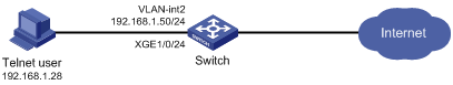
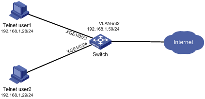
As shown in Figure 1, configure the switch to meet the following requirements:
· The Telnet user is authenticated on the switch in ISP domain bbb.
· The Telnet user is allowed to execute the read and write commands of the ospf and filesystem features after the user passes authentication.
Add a user account named telnetuser on the switch for the Telnet user, and set the user password to aabbcc.
Analysis
To meet the network requirements, you must perform the following tasks:
· Create a user role and configure rules for it. This allows the user role to have access permission to the required commands.
· Assign the user role to the Telnet user, so the Telnet user can obtain the required access permissions.
· Remove the default user role from the Telnet user, so the user can only have the access permissions of the configured user role.
Restrictions and guidelines
When you configure RBAC for local AAA users, follow these restrictions and guidelines:
· An ISP domain cannot be deleted when it is the default ISP domain. Before you use the undo domain command, change the domain to a non-default ISP domain by using the undo domain default enable command.
· You can create multiple rules for a user role. Each rule is uniquely identified by the rule number. A user role can access all commands permitted by the user role rules.
· If two user-defined rules conflict, the rule with the higher number takes effect. For example, the user role can use the tracert command but not the ping command if the user role contains rules configured by using the following commands:
¡ rule 1 permit command ping
¡ rule 2 permit command tracert
¡ rule 3 deny command ping
Procedures
1. Configure VLAN settings:
# Create VLAN 2.
<Sysname> system-view
[Sysname] vlan 2
[Sysname-vlan2] quit
# Assign Ten-GigabitEthernet 1/0/24 (the interface connected to the Telnet user) to VLAN 2.
[Sysname] interface ten-gigabitethernet 1/0/24
[Sysname-Ten-GigabitEthernet1/0/24] port access vlan 2
[Sysname-Ten-GigabitEthernet1/0/24] quit
# Assign an IP address to VLAN-interface 2.
[Sysname] interface vlan-interface 2
[Sysname-Vlan-interface2] ip address 192.168.1.50 24
[Sysname-Vlan-interface2] quit
2. Configure the user login authentication method:
# Enable Telnet server.
[Sysname] telnet server enable
# Enable scheme authentication on user lines VTY 0 through VTY 63.
[Sysname] line vty 0 63
[Sysname-line-vty0-63] authentication-mode scheme
[Sysname-line-vty0-63] quit
3. Configure the authentication domain:
# Create ISP domain bbb and enter ISP domain view.
[Sysname] domain bbb
# Configure the authentication and authorization methods as local for login users in the domain.
[Sysname-isp-bbb] authentication login local
[Sysname-isp-bbb] authorization login local
[Sysname-isp-bbb] quit
4. Configure device management user telnetuser:
# Create device management user telnetuser and enter local user view.
[Sysname] local-user telnetuser class manage
# Set the user password to aabbcc in plain text.
[Sysname-luser-manage-telnetuser] password simple aabbcc
# Specify the service type as Telnet.
[Sysname-luser-manage-telnetuser] service-type telnet
[Sysname-luser-manage-telnetuser] quit
5. Configure user role role1:
# Create user role role1 and enter user role view.
[Sysname] role name role1
# Configure rule 1 to permit the user role to access the read and write commands of the ospf feature.
[Sysname-role-role1] rule 1 permit read write feature ospf
# Configure rule 2 to permit the user role to access the read and write commands of the filesystem feature.
[Sysname-role-role1] rule 2 permit read write feature filesystem
[Sysname-role-role1] quit
6. Assign user role role1 to device management user telnetuser:
# Enter the view of the device management user.
[Sysname] local-user telnetuser class manage
# Assign user role role1 to the user.
[Sysname-luser-manage-telnetuser] authorization-attribute user-role role1
# Remove the default user role network-operator from the user.
[Sysname-luser-manage-telnetuser] undo authorization-attribute user-role network-operator
[Sysname-luser-manage-telnetuser] quit
Verifying the configuration
1. Display information about the user role role1.
[Sysname] display role name role1
Role: role1
Description:
VLAN policy: permit (default)
Interface policy: permit (default)
VPN instance policy: permit (default)
-------------------------------------------------------------------
Rule Perm Type Scope Entity
-------------------------------------------------------------------
1 permit RW- feature ospf
2 permit RW- feature filesystem
R:Read W:Write X:Execute
2. Verify that you can Telnet to the switch.
C:\Documents and Settings\user> telnet 192.168.1.50
login: telnetuser@bbb
Password:
******************************************************************************
* Copyright (c) 2004-2019 New H3C Technologies Co., Ltd. All rights reserved.*
* Without the owner's prior written consent, *
* no decompiling or reverse-engineering shall be allowed. *
******************************************************************************
<Sysname>
3. Verify that you have the access permissions of user role role1:
# Verify that you can execute the write commands of the ospf feature. For example, configure OSPF.
<Sysname> system-view
[Sysname] ospf 1
[Sysname-ospf-1] area 0
[Sysname-ospf-1-area-0.0.0.0] network 1.1.1.1 0.0.0.0
[Sysname-ospf-1-area-0.0.0.0] quit
[Sysname-ospf-1] quit
# Verify that you can execute the read commands of the ospf feature.
[Sysname] display ospf
OSPF Process 1 with Router ID 192.168.1.50
OSPF Protocol Information
RouterID: 192.168.1.50 Router type:
Route tag: 0
Multi-VPN-Instance is not enabled
Ext-community type: Domain ID 0x5, Route Type 0x306, Router ID 0x107
Domain ID: 0.0.0.0
Opaque capable
ISPF is enabled
SPF-schedule-interval: 5 50 200
LSA generation interval: 5 50 200
LSA arrival interval: 1000
Transmit pacing: Interval: 20 Count: 3
Default ASE parameters: Metric: 1 Tag: 1 Type: 2
Route preference: 10
ASE route preference: 150
SPF calculation count: 0
RFC 1583 compatible
Graceful restart interval: 120
SNMP trap rate limit interval: 10 Count: 7
Area count: 0 NSSA area count: 0
ExChange/Loading neighbors: 0
# Verify that you can execute the read and write commands of the filesystem feature. For example, specify the source IP address for outgoing FTP packets as 192.168.0.60.
[Sysname] ftp client source ip 192.168.0.60
[Sysname] quit
# Verify that you cannot use the execute commands of the filesystem feature. For example, enter FTP client view.
<Sysname> ftp
Permission denied.
Configuration files
#
telnet server enable
#
vlan 2
#
interface Vlan-interface2
ip address 192.168.1.50 255.255.255.0
#
interface Ten-GigabitEthernet1/0/24
port access vlan 2
#
line vty 0 63
authentication-mode scheme
user-role network-operator
#
domain bbb
authentication login local
authorization login local
#
role name role1
rule 1 permit read write feature ospf
rule 2 permit read write feature filesystem
#
local-user telnetuser class manage
password hash $h$6$kZw1rKFsAY4lhgUz$+teVLy8gmKN4Mr00VWgXQTB8ai94gKHlrys5OkytGf4
kT+nz5X1ZGASjc282CYAR6A1upH2jbmRoTcfDzZ9Gmw==
service-type telnet
authorization-attribute user-role role1
Example: Assigning access permissions to Telnet user through RADIUS server
Network configuration
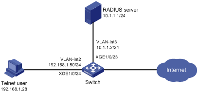
As shown in Figure 2, IMC is the RADIUS server, and the switch uses the RADIUS server to authenticate the Telnet user.
The server assigns the following access permissions to the Telnet user after the user passes authentication:
· Can execute all commands available in ISP domain view.
· Can execute the read and write commands of the ARP and RADIUS features.
· Can create VLANs and execute all commands available in VLAN view.
· Cannot access any VLANs except VLANs 10 to 20.
· Can enter interface view and execute all commands available in interface view.
· Cannot access any interfaces except Ten-GigabitEthernet 1/0/1 to Ten-GigabitEthernet 1/0/3.
Add a user account named telnetuser@bbb on the server for the Telnet user, and specify a password for the account.
Analysis
To meet the network requirements, you must perform the following tasks:
· Add the ARP and RADIUS features to a feature group, so you can manage the features in a centralized manner.
· Create a user role and configure user role rules and resource access policies on the switch, so the user role can have the required access permissions.
· Specify the user role in the Telnet user account on the server, so the server can assign the user role to the Telnet user after the user passes authentication.
Restrictions and guidelines
When you configure RBAC for remote AAA users, follow these guidelines:
· An ISP domain cannot be deleted when it is the default ISP domain. Before you use the undo domain command, change the domain to a non-default ISP domain by using the undo domain default enable command.
· Because RADIUS user authorization information is piggybacked in authentication responses, the authentication and authorization methods must use the same RADIUS scheme.
· You can create multiple rules for a user role. Each rule is uniquely identified by the rule number. A user role can access all commands permitted by the user role rules.
· If two user-defined rules conflict, the rule with the higher number takes effect. For example, the user role can use the tracert command but not the ping command if the user role contains rules configured by using the following commands:
¡ rule 1 permit command ping
¡ rule 2 permit command tracert
¡ rule 3 deny command ping
Procedures
Configuring the switch
1. Configure VLAN settings:
# Create VLAN 2.
<Sysname> system-view
[Sysname] vlan 2
[Sysname-vlan2] quit
# Assign Ten-GigabitEthernet 1/0/24 (the interface connected to the Telnet user) to VLAN 2.
[Sysname] interface ten-gigabitethernet 1/0/24
[Sysname-Ten-GigabitEthernet1/0/24] port access vlan 2
[Sysname-Ten-GigabitEthernet1/0/24] quit
# Assign an IP address to VLAN-interface 2.
[Sysname] interface vlan-interface 2
[Sysname-Vlan-interface2] ip address 192.168.1.50 24
[Sysname-Vlan-interface2] quit
# Create VLAN 3.
[Sysname] vlan 3
[Sysname-vlan3] quit
# Assign Ten-GigabitEthernet 1/0/23 (the interface connected to the RADIUS server) to VLAN 3.
[Sysname] interface ten-gigabitethernet 1/0/23
[Sysname-Ten-GigabitEthernet1/0/23] port access vlan 3
[Sysname-Ten-GigabitEthernet1/0/23] quit
# Assign an IP address to VLAN-interface 3.
[Sysname] interface Vlan-interface 3
[Sysname-Vlan-interface3] ip address 10.1.1.2 24
[Sysname-Vlan-interface3] quit
2. Configure the user login authentication method:
# Enable Telnet server.
[Sysname] telnet server enable
# Enable scheme authentication on user lines VTY 0 through VTY 63.
[Sysname] line vty 0 63
[Sysname-line-vty0-63] authentication-mode scheme
[Sysname-line-vty0-63] quit
3. Configure RADIUS scheme rad:
# Create RADIUS scheme rad and enter RADIUS scheme view.
[Sysname] radius scheme rad
# Specify the primary RADIUS authentication server at 10.1.1.1.
[Sysname-radius-rad] primary authentication 10.1.1.1
# Specify the primary RADIUS accounting server at 10.1.1.1.
[Sysname-radius-rad] primary accounting 10.1.1.1
# Set the authentication shared key to aabbcc in plain text for secure RADIUS communication.
[Sysname-radius-rad] key authentication simple aabbcc
# Set the accounting shared key to aabbcc in plain text for secure RADIUS communication.
[Sysname-radius-rad] key accounting simple aabbcc
[Sysname-radius-rad] quit
4. Configure ISP domain bbb:
# Create ISP domain bbb and enter ISP domain view.
[Sysname] domain bbb
# Configure authentication, authorization, and accounting methods for the login users in the ISP domain.
[Sysname-isp-bbb] authentication login radius-scheme rad
[Sysname-isp-bbb] authorization login radius-scheme rad
[Sysname-isp-bbb] accounting login radius-scheme rad
[Sysname-isp-bbb] quit
5. Configure feature group fgroup1:
# Create feature group fgroup1 and enter feature group view.
[Sysname] role feature-group name fgroup1
# Assign the ARP and RADIUS features to the feature group.
[Sysname-featuregrp-fgroup1] feature arp
[Sysname-featuregrp-fgroup1] feature radius
[Sysname-featuregrp-fgroup1] quit
6. Configure user role role1:
# Create user role role1 and enter user role view.
[Sysname] role name role1
# Configure rule 1 to permit the user role to access all commands in ISP domain view.
[Sysname-role-role1] rule 1 permit command system-view ; domain *
# Configure rule 2 to permit the user role to access all read and write commands of the features in feature group fgroup1.
[Sysname-role-role1] rule 2 permit read write feature-group fgroup1
# Configure rule 3 to permit the user role to create VLANs.
[Sysname-role-role1] rule 3 permit command system-view ; vlan *
# Configure rule 4 to permit the user role to enter interface view and execute all commands available in interface view.
[Sysname-role-role1] rule 4 permit command system-view ; interface *
# Enter user role VLAN policy view, and permit the user role to access only VLANs 10 through 20.
[Sysname-role-role1] vlan policy deny
[Sysname-role-role1-vlanpolicy] permit vlan 10 to 20
[Sysname-role-role1-vlanpolicy] quit
# Enter user role interface policy view, and permit the user role to access only interfaces Ten-GigabitEthernet 1/0/1 through Ten-GigabitEthernet 1/0/3.
[Sysname-role-role1] interface policy deny
[Sysname-role-role1-ifpolicy] permit interface ten-gigabitethernet 1/0/1 to ten-gigabitethernet 1/0/3
[Sysname-role-role1-ifpolicy] quit
[Sysname-role-role1] quit
Configuring the RADIUS server
This example uses IMC PLAT 7.0 (E0202) and IMC UAM 7.0 (E0202) to show the procedure.
1. Add the switch to IMC as an access device:
a. Click the User tab.
b. From the navigation tree, select User Access Policy > Access Device Management > Access Device.
c. Click Add.
The Add Access Device page appears.
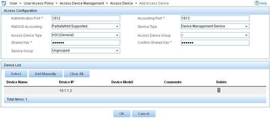
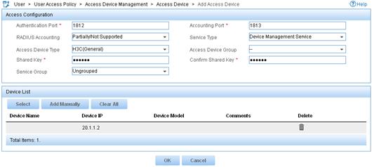
d. In the Access Configuration area, configure the following parameters, as shown in Figure 3:
- Enter 1812 in the Authentication Port field, and enter 1813 in the Accounting Port field.
- Enter aabbcc in the Shared Key and Confirm Shared Key fields.
- Select Device Management Service from the Service Type list.
- Select H3C(General) from the Access Device Type list.
- Use the default values for other parameters.
Figure 3 Adding an access device

e. In the Device List area, click Select or Add Manually to add the switch (10.1.1.2) to IMC as an access device.
f. Click OK.
2. Add a device management user:
a. Click the User tab.
b. From the navigation tree, select Access User > Device User.
c. Click Add.
The Add Device User page appears.
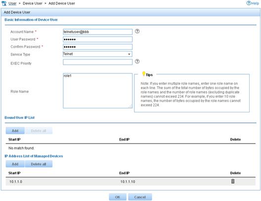
d. In the Basic Information of Device User area, configure the following parameters, as shown in Figure 4:
- Enter telnetuser@bbb in the Account Name field.
- Enter a password in the User Password and Confirm Password fields.
- Select Telnet from the Service Type list.
- Enter role1 in the Role Name field.
Figure 4 Adding a device management user

e. In the IP Address List of Managed Devices area, click Add to specify the IP address subnet in the range of 10.1.1.0 to 10.1.1.10.
f. Click OK.
Verifying the configuration
1. Display information about user role role1.
[Sysname] display role name role1
Role: role1
Description:
VLAN policy: deny
Permitted VLANs: 10 to 20
Interface policy: deny
Permitted interfaces: Ten-GigabitEthernet1/0/1 to Ten-GigabitEthernet1/0/3
VPN instance policy: permit (default)
-------------------------------------------------------------------
Rule Perm Type Scope Entity
-------------------------------------------------------------------
1 permit command system-view ; domain *
2 permit RW- feature-group fgroup1
3 permit command system-view ; vlan *
4 permit command system-view ; interface *
R:Read W:Write X:Execute
2. Verify that you can Telnet to the switch.
C:\Documents and Settings\user> telnet 192.168.1.50
login: telnetuser@bbb
Password:
******************************************************************************
* Copyright (c) 2004-2019 New H3C Technologies Co., Ltd. All rights reserved.*
* Without the owner's prior written consent, *
* no decompiling or reverse-engineering shall be allowed. *
******************************************************************************
<Sysname>
3. Verify that you have the access permissions of user role role1:
# Verify that you can execute all commands available in ISP domain view.
<Sysname> system-view
[Sysname] domain abc
[Sysname-isp-abc] authentication login radius-scheme abc
[Sysname-isp-abc] quit
# Verify that you can execute the read and write commands of the ARP and RADIUS features. For example, configure a RADIUS scheme.
[Sysname] radius scheme rad
[Sysname-radius-rad] primary authentication 2.2.2.2
[Sysname-radius-rad] display radius scheme rad
[Sysname-radius-rad] quit
# Verify that you can access only VLANs 10 to 20. For example, create VLANs 10 and 30.
[Sysname] vlan 10
[Sysname-vlan10] quit
[Sysname] vlan 30
Permission denied.
# Verify that you can access interfaces Ten-GigabitEthernet 1/0/1 to Ten-GigabitEthernet 1/0/3. For example, configure Ten-GigabitEthernet 1/0/1.
[Sysname] interface ten-gigabitethernet 1/0/1
[Sysname-Ten-GigabitEthernet1/0/1] speed auto
[Sysname-Ten-GigabitEthernet1/0/1] quit
# Verify that you cannot access any interface except Ten-GigabitEthernet 1/0/1 to Ten-GigabitEthernet 1/0/3.. For example, enter the view of Ten-GigabitEthernet 1/0/6.
[Sysname] interface ten-gigabitethernet 1/0/6
Permission denied.
Configuration files
#
telnet server enable
#
vlan 2 to 3
#
interface Vlan-interface2
ip address 192.168.1.50 255.255.255.0
#
interface Vlan-interface3
ip address 10.1.1.2 255.255.255.0
#
interface Ten-GigabitEthernet1/0/23
port access vlan 3
#
interface Ten-GigabitEthernet1/0/24
port access vlan 2
#
line vty 0 63
authentication-mode scheme
user-role network-operator
#
radius scheme rad
primary authentication 10.1.1.1
primary accounting 10.1.1.1
key authentication cipher $c$3$JzDegvL0G5KZIcJhzscTHLA4WasBVh0UOw==
key accounting cipher $c$3$CdejNYYxvjW0Y+Zydi4rZgBwjYb4h6LKmg==
#
domain bbb
authentication login radius-scheme rad
authorization login radius-scheme rad
accounting login radius-scheme rad
#
role feature-group name fgroup1
feature arp
feature radius
#
role name role1
rule 1 permit command system-view ; domain *
rule 2 permit read write feature-group fgroup1
rule 3 permit command system-view ; vlan *
rule 4 permit command system-view ; interface *
vlan policy deny
permit vlan 10 to 20
interface policy deny
permit interface Ten-GigabitEthernet1/0/1 to Ten-GigabitEthernet1/0/3
#
Example: Configuring Telnet user to have access to specific commands in specific VPNs
Network configuration
As shown in Figure 5, IMC is the RADIUS server, and the switch uses the RADIUS server to authenticate the Telnet user.
The server authorizes the following access permissions to the Telnet user after the user passes authentication:
· Can execute all commands available in the predefined feature group L3.
· Can execute all commands that start with the display keyword.
· Can access only VPN instances vpn1, vpn2, and vpn3.
Add a user account named telnetuser@bbb on the server for the Telnet user, and specify a password for the account.
Analysis
To meet the network requirements, you must perform the following tasks:
· Create a user role and configure user role rules and resource access policies on the switch, so the user role can have the required access permissions.
· Specify the user role in the Telnet user account on the server, so the server can assign the user role to the Telnet user after the user passes authentication.
Restrictions and guidelines
When you configure RBAC for remote AAA users, follow these restrictions and guidelines:
· An ISP domain cannot be deleted when it is the default ISP domain. Before you use the undo domain command, change the domain to a non-default ISP domain by using the undo domain default enable command.
· Because RADIUS user authorization information is piggybacked in authentication responses, the authentication and authorization methods must use the same RADIUS scheme.
· You can create multiple rules for a user role. Each rule is uniquely identified by the rule number. A user role can access all commands permitted by the user role rules.
· If two user-defined rules conflict, the rule with the higher number takes effect. For example, the user role can use the tracert command but not the ping command if the user role contains rules configured by using the following commands:
¡ rule 1 permit command ping
¡ rule 2 permit command tracert
¡ rule 3 deny command ping
Procedures
Configuring the switch
1. Configure VLAN settings:
# Create VLAN 2.
<Sysname> system-view
[Sysname] vlan 2
[Sysname-vlan2] quit
# Assign Ten-GigabitEthernet 1/0/24 (the interface connected to the Telnet user) to VLAN 2.
[Sysname] interface ten-gigabitethernet 1/0/24
[Sysname-Ten-GigabitEthernet1/0/24] port access vlan 2
[Sysname-Ten-GigabitEthernet1/0/24] quit
# Assign an IP address to VLAN-interface 2.
[Sysname] interface vlan-interface 2
[Sysname-Vlan-interface2] ip address 192.168.1.50 24
[Sysname-Vlan-interface2] quit
# Create VLAN 3.
[Sysname] vlan 3
[Sysname-vlan3] quit
# Assign Ten-GigabitEthernet 1/0/23 (the interface connected to the RADIUS server) to VLAN 3.
[Sysname] interface ten-gigabitethernet 1/0/23
[Sysname-Ten-GigabitEthernet1/0/23] port access vlan 3
[Sysname-Ten-GigabitEthernet1/0/23] quit
# Assign an IP address to VLAN-interface 3.
[Sysname] interface vlan-interface 3
[Sysname-Vlan-interface3] ip address 10.1.1.2 24
[Sysname-Vlan-interface3] quit
2. Configure the user login authentication method:
# Enable Telnet server.
[Sysname] telnet server enable
# Enable scheme authentication on user lines VTY 0 through VTY 63.
[Sysname] line vty 0 63
[Sysname-line-vty0-63] authentication-mode scheme
[Sysname-line-vty0-63] quit
3. Configure RADIUS scheme rad:
# Create RADIUS scheme rad and enter RADIUS scheme view.
[Sysname] radius scheme rad
# Specify the primary RADIUS authentication server at 10.1.1.1.
[Sysname-radius-rad] primary authentication 10.1.1.1
# Specify the primary RADIUS accounting server at 10.1.1.1.
[Sysname-radius-rad] primary accounting 10.1.1.1
# Set the authentication shared key to aabbcc in plain text for secure RADIUS communication.
[Sysname-radius-rad] key authentication simple aabbcc
# Set the accounting shared key to aabbcc in plain text for secure RADIUS communication.
[Sysname-radius-rad] key accounting simple aabbcc
[Sysname-radius-rad] quit
4. Configure ISP domain bbb:
# Create ISP domain bbb and enter ISP domain view.
[Sysname] domain bbb
# Specify the authentication, authorization, and accounting methods for the login users in the ISP domain.
[Sysname-isp-bbb] authentication login radius-scheme rad
[Sysname-isp-bbb] authorization login radius-scheme rad
[Sysname-isp-bbb] accounting login radius-scheme rad
[Sysname-isp-bbb] quit
5. Configure user role role1:
# Create user role role1 and enter user role view.
[Sysname] role name role1
# Configure rule 1 to permit the user role to access all commands in the L3 feature group.
[Sysname-role-role1] rule 1 permit execute read write feature-group L3
# Configure rule 2 to permit the user role to access all commands that start with the display keyword.
[Sysname-role-role1] rule 2 permit command display *
# Enter user role VPN instance policy view, and configure the user role to have access only to VPN instances vpn1, vpn2, and vpn3.
[Sysname-role-role1] vpn policy deny
[Sysname-role-role1-vpnpolicy] permit vpn-instance vpn1 vpn2 vpn3
[Sysname-role-role1-vpnpolicy] quit
[Sysname-role-role1] quit
Configuring the RADIUS server
This example uses IMC PLAT 7.0 (E0202) and IMC UAM 7.0 (E0202) to show the procedure.
1. Add the switch to IMC as an access device:
a. Click the User tab.
b. From the navigation tree, select User Access Policy > Access Device Management > Access Device.
c. Click Add.
The Add Access Device page appears.
d. In the Access Configuration area, configure the following parameters, as shown in Figure 6:
- Enter 1812 in the Authentication Port field, and enter 1813 in the Accounting Port field.
- Enter aabbcc in the Shared Key and Confirm Shared Key fields.
- Select Device Management Service from the Service Type list.
- Select H3C(General) from the Access Device Type list.
- Use the default values for other parameters.
Figure 6 Adding an access device
e. In the Device List area, click Select or Add Manually to add the switch (10.1.1.2) to IMC as an access device.
f. Click OK.
2. Add a device management user:
a. Click the User tab.
b. From the navigation tree, select Access User > Device User.
c. Click Add.
The Add Device User page appears.
d. In the Basic Information of Device User area, configure the following parameters, as shown in Figure 7:
- Enter telnetuser@bbb in the Account Name field.
- Enter a password in the User Password and Confirm Password fields.
- Select Telnet from the Service Type list.
- Enter role1 in the Role Name field.
Figure 7 Adding a device management user
e. In the IP Address List of Managed Devices area, click Add to specify the IP address subnet in the range of 10.1.1.0 to 10.1.1.10.
f. Click OK.
Verifying the configuration
1. Display information about user role role1.
[Sysname] display role name role1
Role: role1
Description:
VLAN policy: permit (default)
Interface policy: permit (default)
VPN instance policy: deny
Permitted VPN instances: vpn1, vpn2, vpn3
-------------------------------------------------------------------
Rule Perm Type Scope Entity
-------------------------------------------------------------------
1 permit RWX feature-group L3
2 permit command display *
R:Read W:Write X:Execute
2. Use the display role feature-group command to display the features in feature group L3. (Details not shown.)
3. Verify that you can Telnet to the switch.
C:\Documents and Settings\user> telnet 192.168.1.50
login: telnetuser@bbb
Password:
******************************************************************************
* Copyright (c) 2004-2019 New H3C Technologies Co., Ltd. All rights reserved.*
* Without the owner's prior written consent, *
* no decompiling or reverse-engineering shall be allowed. *
******************************************************************************
<Sysname>
4. Verify that you have the access permissions of user role role1:
# Verify that you can execute all commands available in the L3 feature group. For example, create VPN instance vpn1 and configure a RD for the VPN instance.
<Sysname> system-view
[Sysname] ip vpn-instance vpn1
[Sysname-vpn-instance-vpn1] route-distinguisher 22:1
[Sysname-vpn-instance-vpn1] display this
#
ip vpn-instance vpn1
route-distinguisher 22:1
#
return
[Sysname-vpn-instance-vpn1] quit
# Verify that you cannot access any VPN instance except vpn1, vpn2, and vpn3. For example, create VPN instance vpn5.
[Sysname] ip vpn-instance vpn5
Permission denied.
Configuration files
#
telnet server enable
#
vlan 2 to 3
#
interface Vlan-interface2
ip address 192.168.1.50 255.255.255.0
#
interface Vlan-interface3
ip address 10.1.1.2 255.255.255.0
#
interface Ten-GigabitEthernet1/0/23
port access vlan 3
#
interface Ten-GigabitEthernet1/0/24
port access vlan 2
#
line vty 0 63
authentication-mode scheme
user-role network-operator
#
radius scheme rad
primary authentication 10.1.1.1
primary accounting 10.1.1.1
key authentication cipher $c$3$JzDegvL0G5KZIcJhzscTHLA4WasBVh0UOw==
key accounting cipher $c$3$CdejNYYxvjW0Y+Zydi4rZgBwjYb4h6LKmg==
#
domain bbb
authentication login radius-scheme rad
authorization login radius-scheme rad
accounting login radius-scheme rad
#
role name role1
rule 1 permit read write execute feature-group L3
rule 2 permit command display *
vpn-instance policy deny
permit vpn-instance vpn1
permit vpn-instance vpn2
permit vpn-instance vpn3
#
Example: Changing user access permissions by assigning new user roles
Network configuration
As shown in Figure 8, add two user accounts telnetuser1 and telnetuser2 on the switch for Telnet user 1 and Telnet user 2, respectively. Set both the users' passwords to aabbcc in plain text.
Configure the switch to meet the following requirements:
· The Telnet users are authenticated on the switch in ISP domain bbb.
· User role role1 is assigned to the Telnet users after they pass authentication.
User role role1 has the following access permissions:
· Can execute all commands that start with the display keyword.
· Can create VLANs.
· Can access only VLANs 10 to 15.
· Can access only interface Ten-GigabitEthernet 1/0/1.
Telnet user 1 requires adding the following access permissions:
· Can access VLANs 16 to 20.
· Can access interfaces Ten-GigabitEthernet 1/0/2 to Ten-GigabitEthernet 1/0/3.
Analysis
To meet the network requirements, you must perform the following tasks:
· Create a user role and configure user role rules and resource access policies, so the user role can have the additional access permissions of Telnet user 1.
· Assign the user role to Telnet user 1, so the user can have the additional access permissions at the next login.
Restrictions and guidelines
When you assign another user role to a user, follow these restrictions and guidelines:
· You can create multiple rules for a user role. Each rule is uniquely identified by the rule number. A user role can access all commands permitted by the user role rules.
· If two user-defined rules conflict, the rule with the higher number takes effect. For example, the user role can use the tracert command but not the ping command if the user role contains rules configured by using the following commands:
¡ rule 1 permit command ping
¡ rule 2 permit command tracert
¡ rule 3 deny command ping
· You can assign multiple user roles to a user. The user can use the collection of items and resources accessible to any user role assigned to it.
· If you assign a new user role to a user when the user is online, the assignment does not take effect on the user at the current login. The user obtains the user role the next time it logs in to the switch.
Procedures
Assigning user role role1 to the Telnet users
1. Configure VLAN settings:
# Create VLAN 2.
<Sysname> system-view
[Sysname] vlan 2
[Sysname-vlan2] quit
# Assign interfaces Ten-GigabitEthernet 1/0/23 and Ten-GigabitEthernet 1/0/24 (the interfaces connected to the Telnet users) to VLAN 2.
[Sysname] interface ten-gigabitethernet 1/0/23
[Sysname-Ten-GigabitEthernet1/0/23] port access vlan 2
[Sysname-Ten-GigabitEthernet1/0/23] quit
[Sysname] interface ten-gigabitethernet 1/0/24
[Sysname-Ten-GigabitEthernet1/0/24] port access vlan 2
[Sysname-Ten-GigabitEthernet1/0/24] quit
# Assign an IP address to VLAN-interface 2.
[Sysname] interface vlan-interface 2
[Sysname-Vlan-interface2] ip address 192.168.1.50 24
[Sysname-Vlan-interface2] quit
2. Configure the user login authentication method:
# Enable Telnet server.
[Sysname] telnet server enable
# Enable scheme authentication on user lines VTY 0 through VTY 63.
[Sysname] line vty 0 63
[Sysname-line-vty0-63] authentication-mode scheme
[Sysname-line-vty0-63] quit
3. Configure ISP domain bbb:
# Create ISP domain bbb and enter ISP domain view.
[Sysname] domain bbb
# Configure the authentication and authorization methods for the login users in the ISP domain.
[Sysname-isp-bbb] authentication login local
[Sysname-isp-bbb] authorization login local
[Sysname-isp-bbb] quit
4. Configure device management users telnetuser1 and telnetuser2:
# Create device management user telnetuser1 and enter local user view.
[Sysname] local-user telnetuser1 class manage
# Set the password to aabbcc in plain text.
[Sysname-luser-manage-telnetuser1] password simple aabbcc
# Specify the service type as Telnet.
[Sysname-luser-manage-telnetuser1] service-type telnet
[Sysname-luser-manage-telnetuser1] quit
# Create device management user telnetuser2 and enter local user view.
[Sysname] local-user telnetuser2 class manage
# Set the password to aabbcc in plain text.
[Sysname-luser-manage-telnetuser2] password simple aabbcc
# Specify the service type as Telnet.
[Sysname-luser-manage-telnetuser2] service-type telnet
[Sysname-luser-manage-telnetuser2] quit
5. Configure user role role1:
# Create user role role1 and enter user role view.
[Sysname] role name role1
# Configure rule 1 to permit the user role to access all commands that start with the display keyword.
[Sysname-role-role1] rule 1 permit command display *
# Configure rule 2 to permit the user role to access VLAN view.
[Sysname-role-role1] rule 2 permit command system-view ; vlan *
# Configure rule 3 to permit the user role to enter interface view and execute all commands available in interface view.
[Sysname-role-role1] rule 3 permit command system-view ; interface *
# Enter user role VLAN policy view, and allow the user role to access only VLANs 10 to 15.
[Sysname-role-role1] vlan policy deny
[Sysname-role-role1-vlanpolicy] permit vlan 10 to 15
[Sysname-role-role1-vlanpolicy] quit
# Enter user role interface policy view, and allow the user role to access only interface Ten-GigabitEthernet 1/0/1.
[Sysname-role-role1] interface policy deny
[Sysname-role-role1-ifpolicy] permit interface ten-gigabitethernet 1/0/1
[Sysname-role-role1] quit
6. Authorize user role role1 to the device management users:
# Enter the view of telnetuser1.
[Sysname] local-user telnetuser1 class manage
# Assign user role role1 to telnetuser1.
[Sysname-luser-manage-telnetuser1] authorization-attribute user-role role1
# Remove the default user role network-operator from telnetuser1.
[Sysname-luser-manage-telnetuser1] undo authorization-attribute user-role network-operator
[Sysname-luser-manage-telnetuser1] quit
# Enter the view of telnetuser2.
[Sysname] local-user telnetuser2 class manage
# Assign user role role1 to telnetuser2.
[Sysname-luser-manage-telnetuser2] authorization-attribute user-role role1
# Remove the default user role network-operator from telnetuser2.
[Sysname-luser-manage-telnetuser2] undo authorization-attribute user-role network-operator
[Sysname-luser-manage-telnetuser2] quit
Verifying the access permissions of user role role1
1. Display information about user role role1.
[Sysname] display role name role1
Role: role1
Description:
VLAN policy: deny
Permitted VLANs: 10 to 15
Interface policy: deny
Permitted interfaces: Ten-GigabitEthernet1/0/1
VPN instance policy: permit (default)
-------------------------------------------------------------------
Rule Perm Type Scope Entity
-------------------------------------------------------------------
1 permit command display *
2 permit command system-view ; vlan *
3 permit command system-view ; interface *
R:Read W:Write X:Execute
2. Verify that you can Telnet to the switch. This example uses the user account telnetuser1@bbb.
C:\Documents and Settings\user> telnet 192.168.1.50
login: telnetuser1@bbb
Password:
******************************************************************************
* Copyright (c) 2004-2019 New H3C Technologies Co., Ltd. All rights reserved.*
* Without the owner's prior written consent, *
* no decompiling or reverse-engineering shall be allowed. *
******************************************************************************
<Sysname>
3. Verify that you have the access permissions of user role role1:
# Verify that you can configure VLANs 10 to 15. For example, create VLAN 15.
<Sysname> system-view
[Sysname] vlan 15
[Sysname-vlan15] quit
# Verify that you cannot access any other VLAN except VLANs 10 to 15. For example, create VLAN 20.
[Sysname] vlan 20
Permission denied.
# Verify that you can access interface Ten-GigabitEthernet 1/0/1.
[Sysname] interface ten-gigabitethernet 1/0/1
[Sysname-Ten-GigabitEthernet1/0/1] speed auto
[Sysname-Ten-GigabitEthernet1/0/1] quit
Assigning user role role2 to Telnet user 1
1. Configure user role role2:
# Create user role role2 and enter user role view.
[Sysname] role name role2
# Configure rule 1 to permit the user role to enter interface view and execute all commands available in interface view.
[Sysname-role-role2] rule 1 permit command system-view ; interface *
# Enter user role VLAN policy view, and allow the user role to access only VLANs 16 to 20.
[Sysname-role-role2] vlan policy deny
[Sysname-role-role2-vlanpolicy] permit vlan 16 to 20
[Sysname-role-role2-vlanpolicy] quit
# Enter user role interface policy view, and allow the user role to access only interfaces Ten-GigabitEthernet 1/0/2 to Ten-GigabitEthernet 1/0/3.
[Sysname-role-role2] interface policy deny
[Sysname-role-role2-ifpolicy] permit interface ten-gigabitethernet 1/0/2 to ten-gigabitethernet 1/0/3
[Sysname-role-role2-ifpolicy] quit
[Sysname-role-role2] quit
2. Authorize user role role2 to telnetuser1:
# Enter the view of telnetuser1.
[Sysname] local-user telnetuser1 class manage
# Assign user role role2 to telnetuser1.
[Sysname-luser-manage-telnetuser1] authorization-attribute user-role role2
[Sysname-luser-manage-telnetuser1] quit
Verifying the configuration
1. Display information about user role role2.
[Sysname] display role name role2
Role: role2
Description:
VLAN policy: deny
Permitted VLANs: 16 to 20
Interface policy: deny
Permitted interfaces: Ten-GigabitEthernet1/0/2~Ten-GigabitEthernet1/0/3
VPN instance policy: permit (default)
-------------------------------------------------------------------
Rule Perm Type Scope Entity
-------------------------------------------------------------------
1 permit command system-view ; interface *
R:Read W:Write X:Execute
2. Verify that you can Telnet to the switch.
C:\Documents and Settings\user> telnet 192.168.1.50
login: telnetuser1@bbb
Password:
******************************************************************************
* Copyright (c) 2004-2019 New H3C Technologies Co., Ltd. All rights reserved.*
* Without the owner's prior written consent, *
* no decompiling or reverse-engineering shall be allowed. *
******************************************************************************
<Sysname>
3. Verify that you have the access permissions of user role role2:
# Verify that you can access VLANs 16 to 20. For example, create VLAN 16.
<Sysname> system-view
[Sysname] vlan 16
[Sysname-vlan16] quit
# Verify that you can access interfaces Ten-GigabitEthernet 1/0/2 and Ten-GigabitEthernet 1/0/3. For example, configure Ten-GigabitEthernet 1/0/2.
[Sysname] interface ten-gigabitethernet 1/0/2
[Sysname-Ten-GigabitEthernet1/0/2] speed auto
[Sysname-Ten-GigabitEthernet1/0/2] quit
# Verify that you cannot access any other interface except interfaces Ten-GigabitEthernet 1/0/1 to Ten-GigabitEthernet 1/0/3. For example, enter the view of Ten-GigabitEthernet 1/0/5.
[Sysname] interface ten-gigabitethernet 1/0/5
Permission denied.
Configuration files
#
telnet server enable
#
vlan 2
#
interface Vlan-interface2
ip address 192.168.1.50 255.255.255.0
#
interface Ten-GigabitEthernet1/0/23
port access vlan 2
#
interface Ten-GigabitEthernet1/0/24
port access vlan 2
#
line vty 0 63
authentication-mode scheme
user-role network-operator
#
domain bbb
authentication login local
authorization login local
#
role name role1
rule 1 permit command display *
rule 2 permit command system-view ; vlan *
rule 3 permit command system-view ; interface *
vlan policy deny
permit vlan 10 to 15
interface policy deny
permit interface Ten-GigabitEthernet1/0/1
#
role name role2
rule 1 permit command system-view ; interface *
vlan policy deny
permit vlan 16 to 20
interface policy deny
permit interface Ten-GigabitEthernet1/0/2 to Ten-GigabitEthernet1/0/3
#
local-user telnetuser1 class manage
password hash $h$6$kZw1rKFsAY4lhgUz$+teVLy8gmKN4Mr00VWgXQTB8ai94gKHlrys5OkytGf4
kT+nz5X1ZGASjc282CYAR6A1upH2jbmRoTcfDzZ9Gmw==
service-type telnet
authorization-attribute user-role role1
authorization-attribute user-role role2
#
local-user telnetuser2 class manage
password hash TPcgyTQJZShe$h$6$vaSj2xKc8yFiNdfQ$Jzb3PXo2lt4jk KSZqJUVhjP634Wol/
Qx8TLU748IHoeui0w5n/XRzpNqbNnpxikym39gGJCwYw==
service-type telnet
authorization-attribute user-role role1
#
Example: Configuring temporary user role authorization
Network configuration
As shown in Figure 9, the switch performs local AAA authentication for the Telnet user. It assigns user role role1 to the Telnet user after the user passes authentication.
The switch performs local-only authentication for the Telnet user to obtain the user role role2 or network-operator for temporary authorization.
User role role1 has the following access permissions:
· Can execute all commands available in the L3 feature group.
· Can execute all commands that start with the display keyword.
· Can execute all commands that start with the super keyword.
· Can access all interfaces, VLANs, and VPNs.
User role role2 has the following access permissions:
· Can execute all commands available in the L2 feature group.
· Can access all interfaces, VLANs, and VPNs.
Add a user account named telnetuser on the switch for the Telnet user, set the password to aabbcc in plain text.
Analysis
To meet the network requirements, you must perform the following tasks:
· Create user roles role1 and role2, and configure user role rules and resource access policies, so the user roles can have the required access permissions.
· Assign user role role1 to the Telnet user, so the user can obtain the user role after it passes authentication.
· Configure user role authentication settings for role2 and network-operator, so the Telnet user can obtain the user roles for temporary authorization.
· For security purposes, configure different authentication passwords for the user roles role2 and network-operator.
Restrictions and guidelines
When you configure temporary user role authorization, follow these restrictions and guidelines:
· An ISP domain cannot be deleted when it is the default ISP domain. Before you use the undo domain command, change the domain to a non-default ISP domain by using the undo domain default enable command.
· You can create multiple rules for a user role. Each rule is uniquely identified by the rule number. A user role can access all commands permitted by the user role rules.
· If two user-defined rules conflict, the rule with the higher number takes effect. For example, the user role can use the tracert command but not the ping command if the user role contains rules configured by using the following commands:
¡ rule 1 permit command ping
¡ rule 2 permit command tracert
¡ rule 3 deny command ping
· Temporary user role authorization is effective only on the current login. This feature does not change the user role settings in the user account that you have been logged in with. The next time you are logged in with the user account, the original user role settings take effect.
Procedures
1. Configure VLAN settings:
# Create VLAN 2.
<Sysname> system-view
[Sysname] vlan 2
[Sysname-vlan2] quit
# Assign Ten-GigabitEthernet 1/0/24 (the interface connected to the Telnet user) to VLAN 2.
[Sysname] interface ten-gigabitethernet 1/0/24
[Sysname-Ten-GigabitEthernet1/0/24] port access vlan 2
[Sysname-Ten-GigabitEthernet1/0/24] quit
# Assign an IP address to VLAN-interface 2.
[Sysname] interface vlan-interface 2
[Sysname-Vlan-interface2] ip address 192.168.1.50 24
[Sysname-Vlan-interface2] quit
2. Configure the user login authentication method:
# Enable Telnet server.
[Sysname] telnet server enable
# Enable scheme authentication on user lines VTY 0 through VTY 63.
[Sysname] line vty 0 63
[Sysname-line-vty0-63] authentication-mode scheme
[Sysname-line-vty0-63] quit
3. Configure ISP domain bbb:
# Create ISP domain bbb and enter ISP domain view.
[Sysname] domain bbb
# Configure the authentication and authorization methods for the login users in the ISP domain.
[Sysname-isp-bbb] authentication login local
[Sysname-isp-bbb] authorization login local
[Sysname-isp-bbb] quit
4. Configure device management user telnetuser:
# Create device management user telnetuser and enter local user view.
[Sysname] local-user telnetuser class manage
# Set the user password to aabbcc in plain text.
[Sysname-luser-manage-telnetuser] password simple aabbcc
# Specify the service type as Telnet.
[Sysname-luser-manage-telnetuser] service-type telnet
[Sysname-luser-manage-telnetuser] quit
5. Configure user role role1:
# Create user role role1 and enter user role view.
[Sysname] role name role1
# Configure rule 1 to permit the user role to access all commands of the L3 feature group.
[Sysname-role-role1] rule 1 permit execute read write feature-group L3
# Configure rule 2 to permit the user role to access all commands that start with the display keyword.
[Sysname-role-role1] rule 2 permit command display *
# Configure rule 3 to permit the user role to access all commands that start with the super keyword.
[Sysname-role-role1] rule 3 permit command super *
[Sysname-role-role1] quit
6. Configure user role role2:
# Create user role role2 and enter user role view.
[Sysname] role name role2
# Configure rule 1 to permit the user role to access all commands of the L2 feature group.
[Sysname-role-role2] rule 1 permit execute read write feature-group L2
[Sysname-role-role2] quit
7. Authorize user role role1 to device management user telnetuser:
# Enter the view of the device management user.
[Sysname] local-user telnetuser class manage
# Authorize user role role1 to the user.
[Sysname-luser-manage-telnetuser] authorization-attribute user-role role1
# Remove the default user role network-operator from the user.
[Sysname-luser-manage-telnetuser] undo authorization-attribute user-role network-operator
[Sysname-luser-manage-telnetuser] quit
8. Configure temporary user role authorization:
# Enable local-only authentication for temporary user role authorization.
[Sysname] super authentication-mode local
# Set the local authentication password to 123456TESTplat&! in plain text for user role role2.
[Sysname] super password role role2 simple 123456TESTplat&!
# Set the local authentication password to 987654TESTplat&! in plain text for user role network-operator.
[Sysname] super password role network-operator simple 987654TESTplat&!
Verifying the configuration
1. Verify that the user roles are correctly configured:
# Display information about user role role1.
[Sysname] display role name role1
Role: role1
Description:
VLAN policy: permit (default)
Interface policy: permit (default)
VPN instance policy: permit (default)
-------------------------------------------------------------------
Rule Perm Type Scope Entity
-------------------------------------------------------------------
1 permit RWX feature-group L3
2 permit command display *
3 permit command super *
R:Read W:Write X:Execute
# Display information about user role role2.
[Sysname] display role name role2
Role: role2
Description:
VLAN policy: permit (default)
Interface policy: permit (default)
VPN instance policy: permit (default)
-------------------------------------------------------------------
Rule Perm Type Scope Entity
-------------------------------------------------------------------
1 permit RWX feature-group L2
R:Read W:Write X:Execute
# Display information about user role network-operator.
[Sysname] display role name network-operator
Role: network-operator
Description: Predefined network operator role has access to all read commands
on the device
VLAN policy: permit (default)
Interface policy: permit (default)
VPN instance policy: permit (default)
-------------------------------------------------------------------
Rule Perm Type Scope Entity
-------------------------------------------------------------------
sys-1 permit command display *
sys-2 permit command xml
sys-3 permit command system-view ; probe ; display *
sys-4 deny command display history-command all
sys-5 deny command display exception *
sys-6 deny command display cpu-usage configuration
*
sys-7 deny command display kernel exception *
sys-8 deny command display kernel deadloop *
sys-9 deny command display kernel starvation *
sys-10 deny command display kernel reboot *
sys-11 deny command display memory trace *
sys-12 deny command display kernel memory *
sys-13 permit command system-view ; local-user *
sys-14 permit command system-view ; switchto mdc *
sys-16 permit R-- web-menu -
sys-17 permit RW- web-menu m_device/m_maintenance/
m_changepassword
sys-18 permit R-- xml-element -
sys-19 deny command display security-logfile summary
sys-20 deny command display security-logfile buffer
sys-21 deny command system-view ; info-center
security-logfile directory *
sys-22 deny command security-logfile save
sys-23 deny command system-view ; local-user-import
*
sys-24 deny command system-view ; local-user-export
*
sys-25 permit R-- oid 1
sys-26 deny command display smartmc *
R:Read W:Write X:Execute
2. Use the display role feature-group command to display the features in the L2 and L3 feature groups. (Details not shown.)
3. Verify that you can Telnet to the switch.
C:\Documents and Settings\user> telnet 192.168.1.50
login: telnetuser@bbb
Password:
******************************************************************************
* Copyright (c) 2004-2019 New H3C Technologies Co., Ltd. All rights reserved.*
* Without the owner's prior written consent, *
* no decompiling or reverse-engineering shall be allowed. *
******************************************************************************
<Sysname>
4. Verify that you have the access permissions of user role role1:
# Verify that you can access all commands in the L3 feature group. For example, create VPN vpn1.
<Sysname> system-view
[Sysname] ip vpn-instance vpn1
[Sysname-vpn-instance-vpn1] quit
# Verify that you can use all commands that start with the display keyword. For example, display the system time and date.
[Sysname] display clock
09:31:56 UTC Tue 01/01/2019
[Sysname] quit
5. Verify that you can obtain the authorization of user role role2 without reconnecting to the switch:
# Obtain the user role role2.
<Sysname> super role2
Password:
User privilege role is role2, and only those commands that authorized to the role can be used.
<Sysname>
# Verify that you can use all commands in the L2 feature group. For example, create VLAN 10.
<Sysname> system-view
[Sysname] vlan 10
[Sysname-vlan10] quit
[Sysname] quit
# Verify that you cannot use the commands of any features except the features in the L2 feature group. For example, obtain the user role network-operator for temporary authorization.
<Sysname> super network-operator
Permission denied.
# Verify that you cannot use the commands that start with the display keyword. For example, display the system date and time.
<Sysname> display clock
Permission denied.
6. Disconnect from the switch, and Telnet to the switch again.
C:\Documents and Settings\user> telnet 192.168.1.50
login: telnetuser@bbb
Password:
******************************************************************************
* Copyright (c) 2004-2019 New H3C Technologies Co., Ltd. All rights reserved.*
* Without the owner's prior written consent, *
* no decompiling or reverse-engineering shall be allowed. *
******************************************************************************
<Sysname>
7. Verify that you can obtain the network-operator user role.
<Sysname> super network-operator
Password:
User privilege role is network-operator, and only those commands that authorized
to the role can be used.
<Sysname>
Configuration files
#
telnet server enable
#
vlan 2
#
interface Vlan-interface2
ip address 192.168.1.50 255.255.255.0
#
interface Ten-GigabitEthernet1/0/24
port access vlan 2
#
line vty 0 63
authentication-mode scheme
user-role network-operator
#
super password role role2 hash $h$6$D0kjHFktkktzgR5g$e673xFnIcKytCj6EDAw+pvwgh3
/ung3WNWHnrUTnXT862B+s7PaLfKTdil8ef71RBOvuJvPAZHjiLjrMPyWHQw==
super password role network-operator hash $h$6$3s5KMmscn9hJ6gPx$IcxbNjUc8u4yxwR
m87b/Jki8BoPAxw/s5bEcPQjQj/cbbXwTVcnQGL91WOd7ssO2rX/wKzfyzAO5VhBTn9Q4zQ==
#
domain bbb
authentication login local
authorization login local
#
role name role1
rule 1 permit read write execute feature-group L3
rule 2 permit command display *
rule 3 permit command super *
#
role name role2
rule 1 permit read write execute feature-group L2
#
local-user telnetuser class manage
password hash $h$6$kZw1rKFsAY4lhgUz$+teVLy8gmKN4Mr00VWgXQTB8ai94gKHlrys5OkytGf4
kT+nz5X1ZGASjc282CYAR6A1upH2jbmRoTcfDzZ9Gmw==
service-type telnet
authorization-attribute user-role role1
#
Example: Assigning ACL and QoS access permissions to Telnet users
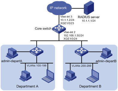
Network configuration
As shown in Figure 10, the core switch is an S7500E switch, and IMC is the RADIUS server. Users in Department A are in VLANs 100 to 199, and users in Department B are in VLANs 200 to 299. Users in the two departments cannot reach each other at Layer 2.
Add Telnet user accounts admin-departA@bbb and admin-departB@bbb on the RADIUS server for the network administrators in Department A and Department B, respectively.
The core switch uses the RADIUS server to authenticate the network administrators in ISP domain bbb.
The server authorizes the following access permissions to admin-departA after it passes authentication:
· Can access all commands of the ACL and QoS features.
· Cannot access any interface and VPN.
· Can access only VLANs 100 to 199.
The server authorizes the following access permissions to admin-departB after it passes authentication:
· Can access all commands of the ACL and QoS features.
· Cannot access any interface and VPN.
· Can access only VLANs 200 to 299.
Analysis
To meet the network requirements, you must perform the following tasks:
· Create a user role and configure user role rules and resource access policies on the core switch for each administrator, so the user roles can have the required access permissions.
· Specify the correct user role in each Telnet user account on the server, so the server can assign the correct user role to each administrator.
Restrictions and guidelines
Because RADIUS user authorization information is piggybacked in authentication responses, the authentication and authorization methods must use the same RADIUS scheme.
Procedures
Configuring the core switch
1. Configure VLAN settings:
# Create VLAN 2.
<Sysname> system-view
[Sysname] vlan 2
[Sysname-vlan2] quit
# Assign Ten-GigabitEthernet 1/0/24 (the interface connected to the Telnet users) to VLAN 2.
[Sysname] interface ten-gigabitethernet 1/0/24
[Sysname-Ten-GigabitEthernet1/0/24] port access vlan 2
[Sysname-Ten-GigabitEthernet1/0/24] quit
# Assign an IP address to VLAN-interface 2.
[Sysname] interface vlan-interface 2
[Sysname-Vlan-interface2] ip address 192.168.1.50 24
[Sysname-Vlan-interface2] quit
# Create VLAN 3.
[Sysname] vlan 3
[Sysname-vlan3] quit
# Assign Ten-GigabitEthernet 1/0/23 (the interface connected to the RADIUS server) to VLAN 3.
[Sysname] interface ten-gigabitethernet 1/0/23
[Sysname-Ten-GigabitEthernet1/0/23] port access vlan 3
[Sysname-Ten-GigabitEthernet1/0/23] quit
# Assign an IP address to VLAN-interface 3.
[Sysname] interface vlan-interface 3
[Sysname-Vlan-interface3] ip address 20.1.1.2 24
[Sysname-Vlan-interface3] quit
2. Configure the user login authentication method:
# Enable Telnet server.
[Sysname] telnet server enable
# Enable scheme authentication on user lines VTY 0 through VTY 63.
[Sysname] line vty 0 63
[Sysname-line-vty0-63] authentication-mode scheme
[Sysname-line-vty0-63] quit
3. Configure RADIUS scheme rad:
# Create RADIUS scheme rad and enter RADIUS scheme view.
[Sysname] radius scheme rad
# Specify the primary RADIUS authentication server at 10.1.1.1.
[Sysname-radius-rad] primary authentication 10.1.1.1
# Specify the primary RADIUS accounting server at 10.1.1.1.
[Sysname-radius-rad] primary accounting 10.1.1.1
# Set the authentication shared key to aabbcc in plain text for secure RADIUS communication.
[Sysname-radius-rad] key authentication simple aabbcc
# Set the accounting shared key to aabbcc in plain text for secure RADIUS communication.
[Sysname-radius-rad] key accounting simple aabbcc
[Sysname-radius-rad] quit
4. Configure ISP domain bbb:
# Create ISP domain bbb and enter ISP domain view.
[Sysname] domain bbb
# Configure authentication, authorization, and accounting methods for the login users in the ISP domain.
[Sysname-isp-bbb] authentication login radius-scheme rad
[Sysname-isp-bbb] authorization login radius-scheme rad
[Sysname-isp-bbb] accounting login radius-scheme rad
[Sysname-isp-bbb] quit
5. Configure user role departA-resource:
# Create user role departA-resource and enter user role view.
[Sysname] role name departA-resource
# Configure rule 1 to permit the user role to access all commands of the QoS feature.
[Sysname-role-departA-resource] rule 1 permit read write execute feature qos
# Configure rule 2 to permit the user role to access all commands of the ACL feature.
[Sysname-role-departA-resource] rule 2 permit read write execute feature acl
# Enter user role VLAN policy view, and permit the user role to access only VLANs 100 to 199.
[Sysname-role-departA-resource] vlan policy deny
[Sysname-role-departA-resource-vlanpolicy] permit vlan 100 to 199
[Sysname-role-departA-resource-vlanpolicy] quit
# Deny the user role to access any interface and VPN.
[Sysname-role-departA-resource] interface policy deny
[Sysname-role-departA-resource-ifpolicy] quit
[Sysname-role-departA-resource] vpn policy deny
[Sysname-role-departA-resource-vpnpolicy] quit
[Sysname-role-departA-resource] quit
6. Configure user role departB-resource:
# Create user role departB-resource and enter user role view.
[Sysname] role name departB-resource
# Configure rule 1 to permit the user role to access all commands of the QoS feature.
[Sysname-role-departB-resource] rule 1 permit read write execute feature qos
# Configure rule 2 to permit the user role to access all commands of the ACL feature.
[Sysname-role-departB-resource] rule 2 permit read write execute feature acl
# Enter user role VLAN policy view, and permit the user role to access only VLANs 200 to 299.
[Sysname-role-departB-resource] vlan policy deny
[Sysname-role-departB-resource-vlanpolicy] permit vlan 200 to 299
[Sysname-role-departB-resource-vlanpolicy] quit
# Deny the user role to access any interface and VPN.
[Sysname-role-departB-resource] interface policy deny
[Sysname-role-departB-resource-ifpolicy] quit
[Sysname-role-departB-resource] vpn policy deny
[Sysname-role-departB-resource-vpnpolicy] quit
[Sysname-role-departB-resource] quit
Configuring the RADIUS server
This example uses IMC PLAT 7.0 (E0202) and IMC UAM 7.0 (E0202) to show the procedure.
1. Add the core switch to IMC as an access device:
a. Click the User tab.
b. From the navigation tree, select User Access Policy > Access Device Management > Access Device.
c. Click Add.
The Add Access Device page appears.
d. In the Access Configuration area, configure the following parameters, as shown in Figure 11:
- Enter 1812 in the Authentication Port field, and enter 1813 in the Accounting Port field.
- Enter aabbcc in the Shared Key and Confirm Shared Key fields.
- Select Device Management Service from the Service Type list.
- Select H3C(General) from the Access Device Type list.
- Use the default values for other parameters.
Figure 11 Adding an access device
e. In the Device List area, click Select or Add Manually to add the core switch (20.1.1.2) to IMC as an access device.
f. Click OK.
2. Add a device management user:
a. Click the User tab.
b. From the navigation tree, select Access User > Device User.
c. Click Add.
The Add Device User page appears.
d. In the Basic Information of Device User area, configure the following parameters, as shown in Figure 12:
- Enter admin-departA@bbb in the Account Name field.
- Enter a password in the User Password and Confirm Password fields.
- Select Telnet from the Service Type list.
- Enter departA-resource in the Role Name field.
Figure 12 Adding a device management user

e. In the IP Address List of Managed Devices area, click Add to specify the IP address subnet in the range of 20.1.1.0 to 20.1.1.10.
f. Click OK.
The device user list displays the added user.
g. Click Add.
The Add Device User page appears.
h. In the Basic Information of Device User area, configure the following parameters, as shown in Figure 13:
- Enter admin-departB@bbb in the Account Name field.
- Enter a password in the User Password and Confirm Password fields.
- Select Telnet from the Service Type list.
- Enter departB-resource in the Role Name field.
Figure 13 Adding a device management user

i. In the IP Address List of Managed Devices area, click Add to specify the IP address subnet in the range of 20.1.1.0 to 20.1.1.10.
j. Click OK.
Verifying the configuration
1. Verify that the user roles are correctly configured:
# Display information about user role departA-resource.
[Sysname] display role name departA-resource
Role: departA-resource
Description:
VLAN policy: deny
Permitted VLANs: 100 to 199
Interface policy: deny
VPN instance policy: deny
-------------------------------------------------------------------
Rule Perm Type Scope Entity
-------------------------------------------------------------------
1 permit RWX feature qos
2 permit RWX feature acl
R:Read W:Write X:Execute
# Display information about user role departB-resource.
[Sysname] display role name departB-resource
Role: departB-resource
Description:
VLAN policy: deny
Permitted VLANs: 200 to 299
Interface policy: deny
VPN instance policy: deny
-------------------------------------------------------------------
Rule Perm Type Scope Entity
-------------------------------------------------------------------
1 permit RWX feature qos
2 permit RWX feature acl
R:Read W:Write X:Execute
2. Verify that you can Telnet to the core switch by using the account admin-departA@bbb from Department A:
C:\Documents and Settings\user> telnet 192.168.1.50
login: admin-departA@bbb
Password:
******************************************************************************
* Copyright (c) 2004-2019 New H3C Technologies Co., Ltd. All rights reserved.*
* Without the owner's prior written consent, *
* no decompiling or reverse-engineering shall be allowed. *
******************************************************************************
<Sysname>
3. Verify that you have the access permission of user role departA-resource:
a. Verify that you can use all commands of the QoS and ACL features:
# Create IPv4 advanced ACL 3000 and enter ACL view.
<Sysname> system-view
[Sysname] acl advanced 3000
# Create an IPv4 advanced ACL rule to permit outbound FTP packets.
[Sysname-acl-ipv4-adv-3000] rule permit tcp destination-port eq ftp-data
[Sysname-acl-ipv4-adv-3000] quit
# Create traffic class 1 and enter traffic class view.
[Sysname] traffic classifier 1
# Define a match criterion for traffic class 1 to match the advanced ACL 3000.
[Sysname-classifier-1] if-match acl 3000
[Sysname-classifier-1] quit
# Create traffic behavior 1 and enter traffic behavior view.
[Sysname] traffic behavior 1
# Set the CIR of the CAR action to 2000 kbps.
[Sysname-behavior-1] car cir 2000
[Sysname-behavior-1] quit
# Create QoS policy 1, and associate traffic class 1 with traffic behavior 1 in the QoS policy.
[Sysname] qos policy 1
[Sysname-qospolicy-1] classifier 1 behavior 1
[Sysname-qospolicy-1] quit
b. Verify that you can access VLANs 100 through 199. For example, apply QoS policy 1 to the incoming traffic of VLANs 100 through 107.
[Sysname] qos vlan-policy 1 vlan 100 to 107 inbound
c. Verify that you cannot access any other VLANs except VLANs 100 through 199. For example, apply QoS policy 1 to the incoming traffic of VLANs 200 through 207.
[Sysname] qos vlan-policy 1 vlan 200 to 207 inbound
Permission denied.
4. Verify that you can Telnet to the core switch by using the account admin-departB@bbb from Department B. (Details not shown.)
5. Verify that you have the access permission of user role departB-resource:
a. Verify that you can use all commands of the QoS and ACL features:
# Create IPv4 advanced ACL 3001 and enter ACL view.
<Sysname> system-view
[Sysname] acl advanced 3001
# Create an IPv4 advanced ACL rule to permit outbound FTP packets.
[Sysname-acl-ipv4-adv-3001] rule permit tcp destination-port eq ftp-data
[Sysname-acl-ipv4-adv-3001] quit
# Create traffic class 2 and enter traffic class view.
[Sysname] traffic classifier 2
# Define a match criterion for traffic class 2 to match the advanced ACL 3001.
[Sysname-classifier-2] if-match acl 3001
[Sysname-classifier-2] quit
# Create traffic behavior 2 and enter traffic behavior view.
[Sysname] traffic behavior 2
# Set the CIR of the CAR action to 2000 kbps.
[Sysname-behavior-2] car cir 2000
[Sysname-behavior-2] quit
# Create QoS policy 2, and associate traffic class 2 with traffic behavior 2 in the QoS policy.
[Sysname] qos policy 2
[Sysname-qospolicy-2] classifier 2 behavior 2
[Sysname-qospolicy-2] quit
b. Verify that you can access VLANs 200 through 299. For example, apply QoS policy 2 to the incoming traffic of VLANs 200 through 207.
[Sysname] qos vlan-policy 2 vlan 200 to 207 inbound
c. Verify that you cannot access any other VLANs except VLANs 200 through 299. For example, apply QoS policy 2 to the incoming traffic of VLANs 100 through 107.
[Sysname] qos vlan-policy 2 vlan 100 to 107 inbound
Permission denied.
Configuration files
#
telnet server enable
#
vlan 2 to 3
#
interface Vlan-interface2
ip address 192.168.1.50 255.255.255.0
#
interface Vlan-interface3
ip address 20.1.1.2 255.255.255.0
#
interface Ten-GigabitEthernet1/0/23
port access vlan 3
#
interface Ten-GigabitEthernet1/0/24
port access vlan 2
#
line vty 0 63
authentication-mode scheme
user-role network-operator
#
radius scheme rad
primary authentication 10.1.1.1
primary accounting 10.1.1.1
key authentication cipher $c$3$JzDegvL0G5KZIcJhzscTHLA4WasBVh0UOw==
key accounting cipher $c$3$CdejNYYxvjW0Y+Zydi4rZgBwjYb4h6LKmg==
#
domain bbb
authentication login radius-scheme rad
authorization login radius-scheme rad
accounting login radius-scheme rad
#
role name departA-resource
rule 1 permit read write execute feature qos
rule 2 permit read write execute feature acl
vlan policy deny
permit vlan 100 to 199
interface policy deny
vpn-instance policy deny
#
role name departB-resource
rule 1 permit read write execute feature qos
rule 2 permit read write execute feature acl
vlan policy deny
permit vlan 200 to 299
interface policy deny
vpn-instance policy deny
#
Related documentation
· H3C S7500E Switch Series Fundamentals Configuration Guide-R758X
· H3C S7500E Switch Series Fundamentals Command Reference-R758X