- Table of Contents
- Related Documents
-
| Title | Size | Download |
|---|---|---|
| 01-EVPN configuration | 394.49 KB |
Contents
Assignment of traffic to VXLANs
Traffic from the local site to a remote site
Traffic from a remote site to the local site
RD and route targets of BGP EVPN routes
Restrictions and guidelines: EVPN configuration
Restrictions and guidelines for VXLAN configuration on a VSI
Restrictions and guidelines for EVPN multihoming
Assigning an ESI to an interface
Disabling advertisement of EVPN multihoming routes
Configuring BGP to advertise BGP EVPN routes
Restrictions and guidelines for BGP EVPN route advertisement
Enabling BGP to advertise BGP EVPN routes
Configuring optimal route selection and route advertisement settings
Mapping a static Ethernet service instance to a VSI
Mapping dynamic Ethernet service instances to VSIs
Managing remote MAC address entries and remote ARP or ND learning
Disabling remote MAC address learning and remote ARP or ND learning
Disabling MAC address advertisement
Disabling learning of MAC addresses from ARP or ND information
Enabling conversational learning for remote MAC address entries
Enabling ARP or ND flood suppression
Enabling packet statistics for VXLAN tunnels
Configuring EVPN distributed relay
Display and maintenance commands for EVPN
Example: Configuring an EVPN network
EVPN overview
Ethernet Virtual Private Network (EVPN) is a Layer 2 VPN technology that provides both Layer 2 and Layer 3 connectivity between distant network sites across an IP network. EVPN uses MP-BGP in the control plane and VXLAN in the data plane. EVPN is typically used in data centers for multitenant services.
EVPN provides the following benefits:
· Configuration automation—MP-BGP automates VTEP discovery, VXLAN tunnel establishment, and VXLAN tunnel assignment to ease deployment.
· Separation of the control plane and the data plane—EVPN uses MP-BGP to advertise host reachability information in the control plane and uses VXLAN to forward traffic in the data plane.
· Integrated routing and bridging (IRB)—MP-BGP advertises both Layer 2 and Layer 3 host reachability information to provide optimal forwarding paths and minimize flooding.
EVPN network model
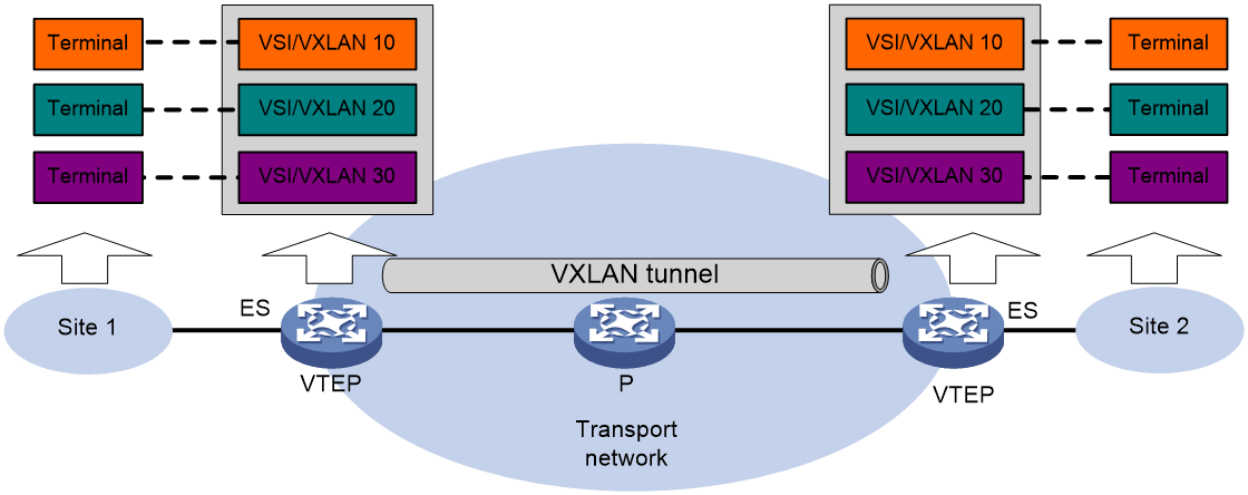
As shown in Figure 1, EVPN uses the VXLAN technology for traffic forwarding in the data plane. The transport edge devices assign user terminals to different VXLANs, and then forward traffic between sites for user terminals by using VXLAN tunnels. The transport edge devices are VXLAN tunnel endpoints (VTEPs).
Supported user terminals include PCs, wireless terminals, and VMs on servers.
|
|
NOTE: This document uses VMs as examples to describe the mechanisms of EVPN. The mechanisms do not differ between different kinds of user terminals. |
A VTEP uses ESs, VSIs, and VXLAN tunnels to provide VXLAN services:
· Ethernet segment (ES)—An ES is a link that connects a site to a VTEP. Each ES is uniquely identified by an Ethernet segment identifier (ESI).
· VSI—A virtual switch instance is a virtual Layer 2 switched domain. Each VSI provides switching services only for one VXLAN. VSIs learn MAC addresses and forward frames independently of one another. User terminals in different sites have Layer 2 connectivity if they are in the same VXLAN. A VXLAN is identified by a 24-bit VXLAN ID which is also called the virtual network identifier (VNI). A VXLAN corresponds to an EVPN instance.
· VXLAN tunnel—Logical point-to-point tunnels between VTEPs over the transport network. Each VXLAN tunnel can trunk multiple VXLANs.
All VXLAN processing is performed on VTEPs. The ingress VTEP encapsulates VXLAN traffic in the VXLAN, outer UDP, and outer IP headers, and forwards the traffic through VXLAN tunnels. The egress VTEP removes the VXLAN encapsulation and forwards the traffic to the destination. Transport network devices (for example, the P device in Figure 1) forward VXLAN traffic only based on the outer IP header of VXLAN packets.
Layered transport network
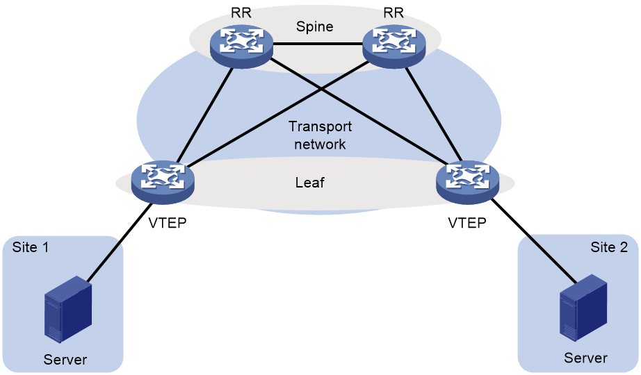
As shown in Figure 2, typically the EVPN transport network uses a layered structure. On the transport network, leaf nodes act as VTEPs to provide VXLAN services, and spine nodes perform forwarding for VXLAN traffic based on the outer IP header. If all VTEPs and transport network devices of an EVPN network belong to the same AS, the spine nodes can act as route reflectors (RRs) to reflect routes between the VTEPs. In this scenario, the spine nodes advertise and receive BGP EVPN routes, but do not perform VXLAN encapsulation and de-encapsulation.
Figure 2 Layered transport network
MP-BGP extension for EVPN
To support EVPN, MP-BGP introduces the EVPN subsequent address family under the L2VPN address family and the following network layer reachability information (BGP EVPN routes):
· Ethernet auto-discovery route—Advertises ES information in multihomed sites.
· MAC/IP advertisement route—Advertises MAC reachability information and host route information (host ARP or ND information).
· Inclusive multicast Ethernet tag (IMET) route—Advertises VTEP and VXLAN mappings for automating VTEP discovery, VXLAN tunnel establishment, and VXLAN tunnel assignment.
· Ethernet segment route—Advertises ES and VTEP mappings.
MP-BGP uses the route distinguisher (RD) field to differentiate BGP EVPN routes of different VXLANs and uses route targets to control the advertisement and acceptance of BGP EVPN routes. MP-BGP supports the following types of route targets:
· Export target—A VTEP sets the export targets for BGP EVPN routes learned from the local site before advertising them to remote VTEPs.
· Import target—A VTEP checks the export targets of BGP EVPN routes received from remote VTEPs. The VTEP imports the BGP EVPN routes only when their export targets match the local import targets.
Configuration automation
VTEPs advertise the VXLAN IDs they have through IMET routes. If two VTEPs have the same VXLAN ID, they automatically establish a VXLAN tunnel and assign the tunnel to the VXLAN.
Assignment of traffic to VXLANs
Traffic from the local site to a remote site
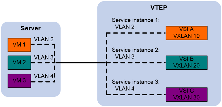
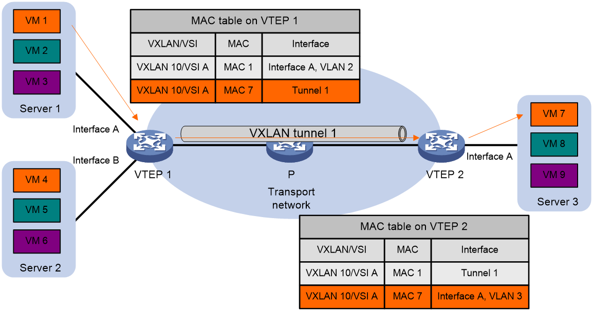
The VTEP uses an Ethernet service instance to match customer traffic on a site-facing interface. The VTEP assigns customer traffic to a VXLAN by mapping the Ethernet service instance to a VSI.
An Ethernet service instance is identical to an attachment circuit (AC) in L2VPN. An Ethernet service instance matches a list of VLANs on a Layer 2 Ethernet interface by using a frame match criterion. The frame match criterion specifies the characteristics of traffic from the VLANs, such as tagging status and VLAN IDs.
As shown in Figure 3, Ethernet service instance 1 matches VLAN 2 and is mapped to VSI A (VXLAN 10). When a frame from VLAN 2 arrives, the VTEP assigns the frame to VXLAN 10, and looks up VSI A's MAC address table for the outgoing interface.
Figure 3 Identifying traffic from the local site
Traffic from a remote site to the local site
When a VXLAN packet arrives at a VXLAN tunnel interface, the VTEP uses the VXLAN ID in the packet to identify its VXLAN.
Layer 2 forwarding
MAC learning
The VTEP performs Layer 2 forwarding based on a VSI's MAC address table. The VTEP learns MAC addresses by using the following methods:
· Local MAC learning—The VTEP automatically learns the source MAC addresses of frames sent from the local site. The outgoing interfaces of local MAC address entries are site-facing interfaces on which the MAC addresses are learned.
· Remote MAC learning—The VTEP uses MP-BGP to advertise local MAC reachability information to remote sites and learn MAC reachability information from remote sites. The outgoing interfaces of MAC address entries advertised from a remote site are VXLAN tunnel interfaces.
Unicast
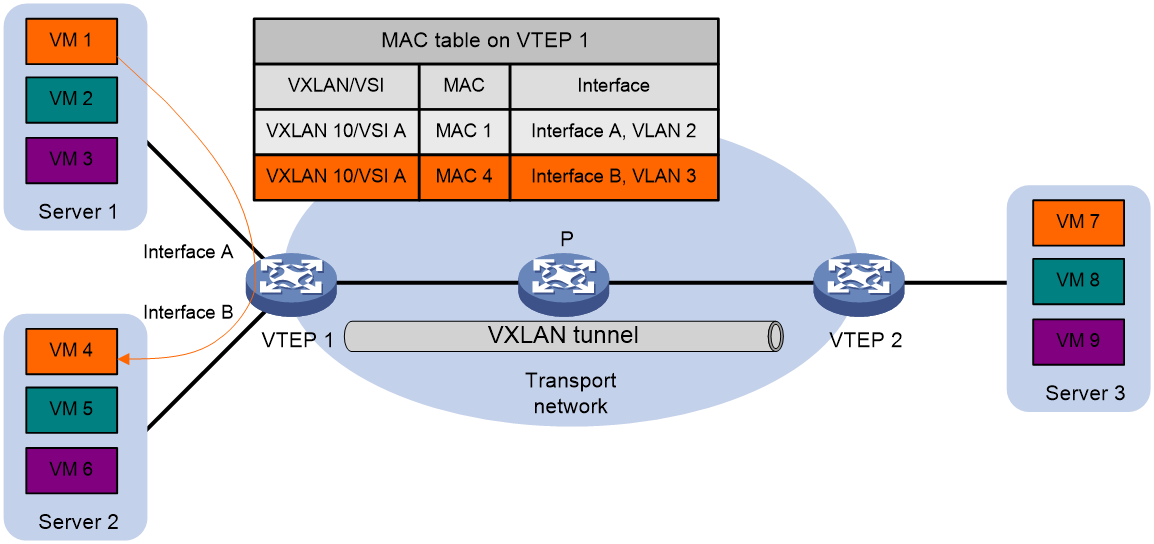
As shown in Figure 4, the VTEP performs typical Layer 2 forwarding for known unicast traffic within the local site.
As shown in Figure 5, the following process applies to a known unicast frame between sites:
1. The source VTEP encapsulates the Ethernet frame in the VXLAN/UDP/IP header.
In the outer IP header, the source IP address is the source VTEP's VXLAN tunnel source IP address. The destination IP address is the VXLAN tunnel destination IP address.
2. The source VTEP forwards the encapsulated packet out of the outgoing VXLAN tunnel interface found in the VSI's MAC address table.
3. The intermediate transport devices (P devices) forward the packet to the destination VTEP by using the outer IP header.
4. The destination VTEP removes the headers on top of the inner Ethernet frame. It then performs MAC address table lookup in the VXLAN's VSI to forward the frame out of the matching outgoing interface.
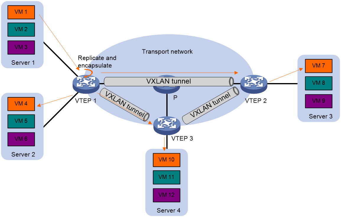
Flood
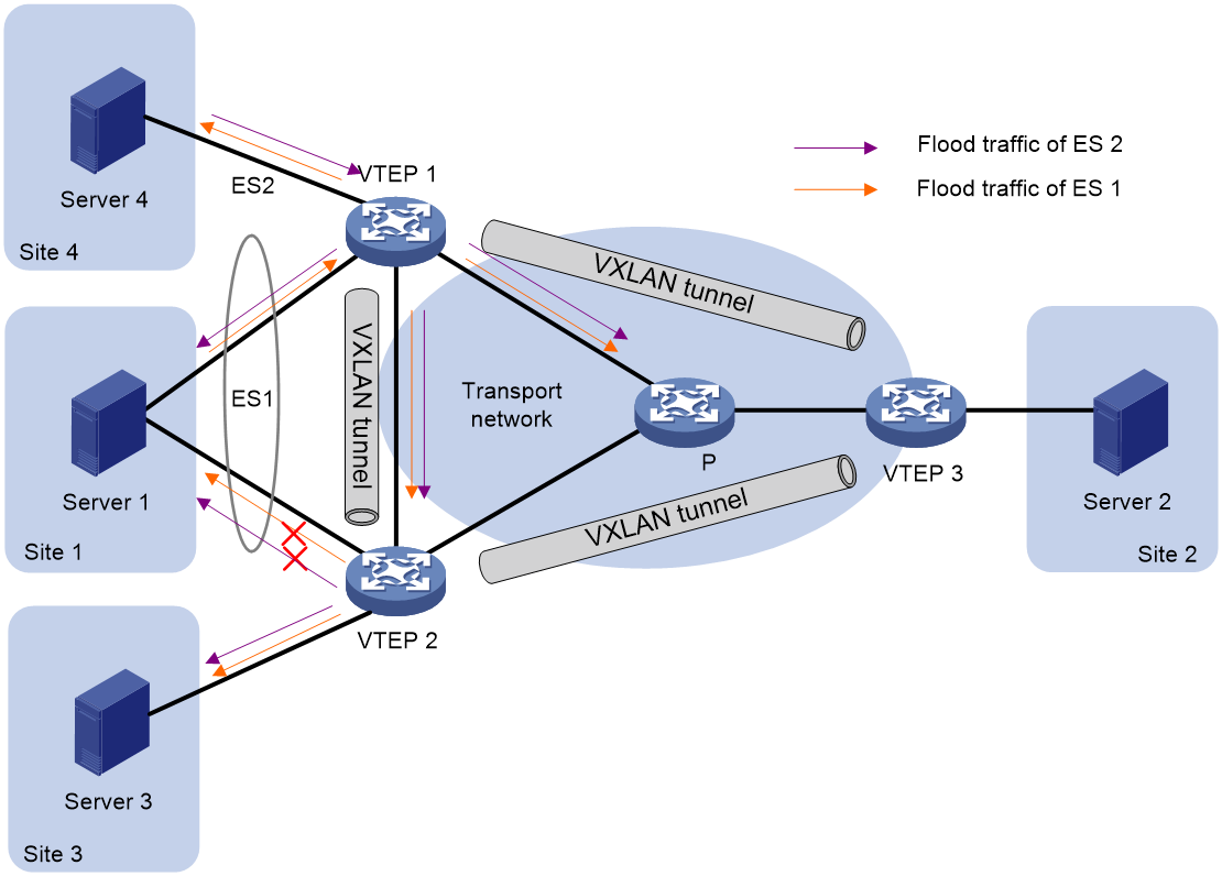
As shown in Figure 6, a VTEP floods a broadcast, multicast, or unknown unicast frame to all site-facing interfaces and VXLAN tunnels in the VXLAN, except for the incoming interface. The source VTEP replicates the flood frame, and then sends one replica to the destination IP address of each VXLAN tunnel in the VXLAN. Each destination VTEP floods the inner Ethernet frame to all the site-facing interfaces in the VXLAN. To avoid loops, the destination VTEPs do not flood the frame to VXLAN tunnels.
Figure 6 Forwarding of flood traffic
RD and route targets of BGP EVPN routes
The device uses the RD and route targets configured in EVPN instance view when advertising and accepting IMET routes and MAC/IP advertisement routes.
EVPN multihoming
|
|
IMPORTANT: EVPN multihoming supports only IPv4 underlay networks. |
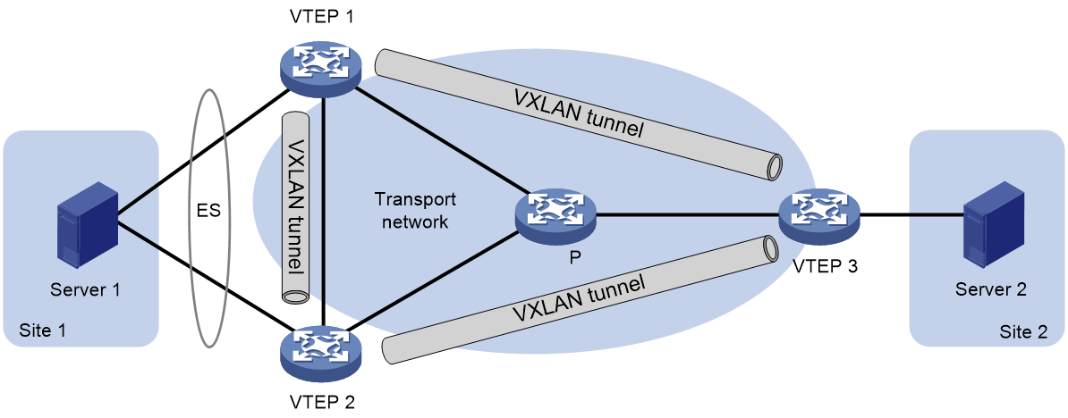
About EVPN multihoming
As shown in Figure 7, EVPN supports deploying multiple VTEPs at a site for redundancy and high availability. On the redundant VTEPs, Ethernet links connected to the site form an Ethernet segment (ES) that is uniquely identified by an Ethernet segment identifier (ESI).
DF election
To prevent redundant VTEPs from sending duplicate flood traffic to a multihomed site, a designated forwarder (DF) is elected from the VTEPs for each AC to forward flood traffic to the AC. VTEPs that fail the election are assigned the backup designated forwarder (BDF) role. BDFs of an AC do not forward flood traffic to the AC.
A remote VTEP takes part in the DF election of a multihomed site. Redundant VTEPs of the site send Ethernet segment routes to the remote VTEP to advertise ES and VTEP IP mappings. Then, the VTEPs select a DF for each AC based on the ES and VTEP IP mappings by using the following procedure:
2. Divide the lowest VLAN ID permitted on an AC by the number of the redundant VTEPs, and match the reminder to the sequence numbers of IP addresses.
3. Assign the DF role to the VTEP that uses the IP address with the matching sequence number.
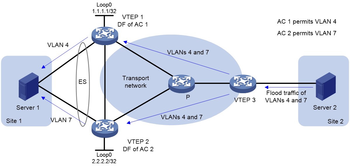
The following uses AC 1 in Figure 8 as an example to explain the DF election procedure:
1. VTEP 1 and VTEP 2 send Ethernet segment routes to VTEP 3.
2. Sequence numbers 0 and 1 are assigned to IP addresses 1.1.1.1 and 2.2.2.2 in the Ethernet segment routes, respectively.
3. The VTEPs divide 4 (the lowest VLAN ID permitted by AC 1) by 2 (the number of redundant VTEPs), and match the reminder 0 to the sequence numbers of the IP addresses.
4. The DF role is assigned to VTEP 1 at 1.1.1.1.
Split horizon
In a multihomed site, a VTEP forwards multicast, broadcast, and unknown unicast frames received from ACs out of all site-facing interfaces and VXLAN tunnels in the corresponding VXLAN, except for the incoming interface. As a result, the other VTEPs at the site receive these flood frames and forward them to site-facing interfaces, which causes duplicate floods and loops. EVPN introduces split horizon to resolve this issue. Split horizon disables a VTEP from forwarding flood traffic received from another local VTEP to site-facing interfaces if an ES on that local VTEP has the same ESI as these interfaces. As shown in Figure 9, both VTEP 1 and VTEP 2 have ES 1. When receiving flood traffic from VTEP 1, VTEP 2 does not forward the traffic to interfaces with ESI 1.
Redundancy mode
The device supports the all-active redundancy mode of EVPN multihoming. This mode allows all redundant VTEPs at a multihomed site to forward broadcast, multicast, and unknown unicast traffic.
· For flood frames received from remotes sites, a VTEP forwards them to the ACs of which it is the DF.
· For flood frames received from the local site, a VTEP forwards them out of all site-facing interfaces and VXLAN tunnels in the corresponding VXLAN, except for the incoming interfaces. For flood frames to be sent out of a VXLAN tunnel interface, a VTEP replicates each flood frame and sends one replica to all the other VTEPs in the corresponding VXLAN.
IP aliasing
In all-active redundancy mode, all redundant VTEPs of an ES advertise the ES to remote VTEPs through MP-BGP. IP aliasing allows a remote VTEP to add the IP addresses of all the redundant VTEPs as the next hops for the MAC or ARP information received from one of these VTEPs. This mechanism creates ECMP routes between the remote VTEP and the redundant VTEPs.
ARP and ND flood suppression
ARP or ND flood suppression reduces ARP request broadcasts or ND request multicasts by enabling the VTEP to reply to ARP or ND requests on behalf of VMs.
As shown in Figure 10, this feature snoops ARP or ND requests, ARP or ND responses, and BGP EVPN routes to populate the ARP or ND flood suppression table with local and remote MAC addresses. If an ARP or ND request has a matching entry, the VTEP replies to the request on behalf of the VM. If no match is found, the VTEP floods the request to both local and remote sites.
Figure 10 ARP and ND flood suppression
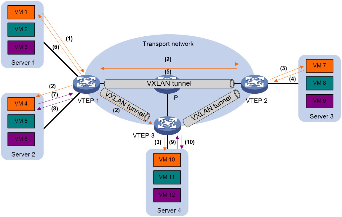
The following uses ARP flood suppression as an example to explain the flood suppression workflow:
1. VM 1 sends an ARP request to obtain the MAC address of VM 7.
2. VTEP 1 creates a suppression entry for VM 1, floods the ARP request in the VXLAN, and sends the suppression entry to VTEP 2 and VTEP 3 through BGP EVPN.
3. VTEP 2 and VTEP 3 de-encapsulate the ARP request and broadcast the request in the local site.
4. VM 7 sends an ARP reply.
5. VTEP 2 creates a suppression entry for VM 7, forwards the ARP reply to VTEP 1, and sends the suppression entry to VTEP 1 and VTEP 3 through BGP EVPN.
6. VTEP 1 de-encapsulates the ARP reply and forwards the ARP reply to VM 1.
7. VM 4 sends an ARP request to obtain the MAC address of VM 1.
8. VTEP 1 creates a suppression entry for VM 4 and replies to the ARP request.
9. VM 10 sends an ARP request to obtain the MAC address of VM 1.
10. VTEP 3 creates a suppression entry for VM 10 and replies to the ARP request.
MAC mobility
MAC mobility refers to that a VM or host moves from one ES to another. The source VTEP is unaware of the MAC move event. To notify other VTEPs of the change, the destination VTEP advertises a MAC/IP advertisement route for the MAC address. The source VTEP withdraws the old route for the MAC address after receiving the new route. The MAC/IP advertisement route has a sequence number that increases when the MAC address moves. The sequence number identifies the most recent move if the MAC address moves multiple times.
EVPN distributed relay
|
|
IMPORTANT: EVPN distributed relay supports only IPv4 sites and IPv4 underlay networks. |
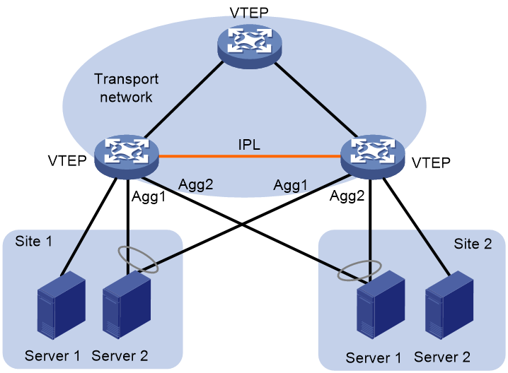
As shown in Figure 11, EVPN distributed relay virtualizes two VTEPs or EVPN gateways into one distributed-relay (DR) system through Distributed Resilient Network Interconnect (DRNI) to avoid single points of failure. The VTEPs or EVPN gateways are called DR member devices. For more information about DRNI, see Layer 2—LAN Switching Configuration Guide.
EVPN distributed relay uses the following mechanisms:
· VM reachability information synchronization—To ensure VM reachability information consistency in the DR system, the DR member devices synchronize MAC address entries and ARP information with each other through an intra-portal link (IPL). The IPL can be an Ethernet aggregate link or a VXLAN tunnel.
|
IMPORTANT: The VXLAN tunnel that acts as the IPL is automatically associated with all VXLANs on each DR member device. |
· Virtual VTEP address—The DR member devices use a virtual VTEP address to set up VXLAN tunnels with remote VTEPs or EVPN gateways.
· Independent BGP neighbor relationship establishment—The DR member devices use different BGP peer addresses to establish neighbor relationships with remote devices. For load sharing and link redundancy, a neighbor sends traffic destined for the virtual VTEP address to both of the DR member devices through ECMP routes of the underlay network.
· Site-facing link redundancy—As shown in Figure 11, a VM accesses the EVPN network through multiple Ethernet links that connect to the VTEPs. On each VTEP, all site-facing Ethernet links are assigned to a Layer 2 aggregation group for high availability. On the corresponding Layer 2 aggregate interfaces, Ethernet service instances are configured as ACs of VXLANs to match customer traffic.
¡ If you specify the Ethernet aggregate link between the VTEPs as the IPL, the site-facing link backup mechanism is as follows:
When a site-facing AC is configured on a DR member device, the device automatically creates an AC on the IPL with the same traffic match criterion as the site-facing AC. Then, it maps the automatically created AC to the VSI of the site-facing AC. When the site-facing AC is down, traffic sent to the AC is forwarded to the other DR member device through the IPL. This mechanism ensures service continuity in case of AC failure.
¡ If a VXLAN tunnel acts as the IPL, the site-facing link backup mechanism is as follows:
If a site-facing AC on a DR member device is down, traffic sent to the AC will be encapsulated into VXLAN packets. The VXLAN ID belongs to the VXLAN that is associated with the VSI of the site-facing AC. The DR member device forwards the VXLAN packets through the IPL VXLAN tunnel to the peer DR member device. The peer DR member device assigns the traffic to the correct VSI based on the VXLAN ID in the received packets.
¡ If you specify the Ethernet aggregate link between the VTEPs as the IPL, the traffic forwarding mechanism is as follows:
When a single-armed AC is configured on a VTEP, the VTEP automatically creates an AC on the IPL with the same traffic match criterion as the single-armed AC. Then, it maps the automatically created AC to the VSI of the single-armed AC. When receiving traffic from the single-armed AC, the VTEP sends the traffic to the other VTEP through the IPL. Then the other VTEP identifies the VSI of the traffic and forwards it.
¡ If a VXLAN tunnel acts as the IPL, the traffic forwarding mechanism is as follows:
When receiving traffic from a single-armed AC, a VTEP encapsulates the traffic into VXLAN packets and sends them to the other VTEP through the IPL. The VXLAN ID in the VXLAN packets belongs to the VSI to which the single-armed AC is mapped. Then the other VTEP identifies the VSI of the traffic and forwards it.
Figure 11 EVPN distributed relay
Configuring EVPN
Restrictions and guidelines: EVPN configuration
Make sure the following VXLAN tunnels are not associated with the same VXLAN when they have the same tunnel destination IP address:
· A VXLAN tunnel automatically created by EVPN.
· A manually created VXLAN tunnel.
For more information about manual tunnel configuration, see VXLAN Configuration Guide.
EVPN tasks at a glance
To configure EVPN, perform the following tasks:
1. Configuring a VXLAN on a VSI
b. (Optional.) Configuring VSI parameters
2. Configuring an EVPN instance
3. (Optional.) Configuring EVPN multihoming
a. Assigning an ESI to an interface
b. (Optional.) Setting the DF election delay
c. Disabling advertisement of EVPN multihoming routes
4. Configuring BGP to advertise BGP EVPN routes
a. Enabling BGP to advertise BGP EVPN routes
b. (Optional.) Configuring optimal route selection and route advertisement settings
c. (Optional.) Maintaining BGP sessions
6. (Optional.) Managing remote MAC address entries and remote ARP or ND learning
¡ Disabling remote MAC address learning and remote ARP or ND learning
¡ Disabling MAC address advertisement
¡ Disabling learning of MAC addresses from ARP or ND information
7. (Optional.) Enabling conversational learning for remote MAC address entries
To save device hardware resources, remote MAC entries are issued to the hardware only when the entries are required for packet forwarding.
8. (Optional.) Maintaining and optimizing an EVPN network
¡ Disabling flooding for a VSI
¡ Enabling ARP or ND flood suppression
¡ Enabling packet statistics for VXLAN tunnels
9. (Optional.) Configuring EVPN distributed relay
Perform this task to virtualize two VTEPs or EVPN gateways into one DR system to avoid single points of failure.
Configuring a VXLAN on a VSI
Restrictions and guidelines for VXLAN configuration on a VSI
For more information about the VXLAN commands in this task, see VXLAN Command Reference.
Creating a VXLAN on a VSI
1. Enter system view.
system-view
2. Enable L2VPN.
l2vpn enable
By default, L2VPN is disabled.
3. Create a VSI and enter VSI view.
vsi vsi-name
4. Enable the VSI.
undo shutdown
By default, a VSI is enabled.
5. Create a VXLAN and enter VXLAN view.
vxlan vxlan-id
You can create only one VXLAN on a VSI. The VXLAN ID must be unique for each VSI.
Configuring VSI parameters
1. Enter system view.
system-view
2. Enter VSI view.
vsi vsi-name
3. Configure a VSI description.
description text
By default, a VSI does not have a description.
4. Set the MTU for the VSI.
mtu size
The default MTU is 1500 bytes for a VSI.
5. Set the maximum bandwidth for known unicast traffic of the VSI.
bandwidth bandwidth
By default, the maximum bandwidth is not limited for known unicast traffic of a VSI.
6. Set the broadcast, multicast, or unknown unicast restraint bandwidth for the VSI.
restrain { broadcast | multicast | unknown-unicast } bandwidth
By default, a VSI's broadcast restraint bandwidth, multicast restraint bandwidth, and unknown unicast restraint bandwidth are not set.
7. Enable MAC address learning for the VSI.
mac-learning enable
By default, MAC address learning is enabled for a VSI.
Configuring an EVPN instance
About EVPN instances
You do not need to associate a VPN instance with a VXLAN that requires only Layer 2 connectivity. The BGP EVPN routes advertised by the device carry the RD and route targets configured for the EVPN instance associated with the VXLAN.
Procedure
1. Enter system view.
system-view
2. Enter VSI view.
vsi vsi-name
3. Create an EVPN instance and enter EVPN instance view.
evpn encapsulation vxlan
4. Configure an RD for the EVPN instance.
route-distinguisher { route-distinguisher | auto [ router-id ] }
By default, no RD is configured for an EVPN instance.
5. Configure route targets for the EVPN instance.
vpn-target { vpn-target&<1-8> | auto } [ both | export-extcommunity | import-extcommunity ]
By default, an EVPN instance does not have route targets.
Configuring EVPN multihoming
Restrictions and guidelines for EVPN multihoming
In a multihomed site, AC configuration and VXLAN IDs must be consistent on redundant VTEPs of the same ES. For each VXLAN ID, you must configure unique RDs for the EVPN instance of VSIs on the redundant VTEPs. You must configure different RDs for the VPN instances and the public instance that use the same VXLAN IP gateway.
Assigning an ESI to an interface
About ESIs
An ESI uniquely identifies an ES. The links on interfaces with the same ESI belong to the same ES. Traffic of the ES can be distributed among the links for load sharing.
Procedure
1. Enter system view.
system-view
2. Enter interface view.
¡ Enter Layer 2 Ethernet interface view.
interface interface-type interface-number
¡ Enter Layer 2 aggregate interface view.
interface bridge-aggregation interface-number
¡ Enter Layer 3 Ethernet interface view.
interface interface-type interface-number
¡ Enter Layer 3 aggregate interface view.
interface route-aggregation interface-number
3. Assign an ESI to the interface.
esi esi-id
By default, no ESI is assigned to an interface.
Setting the DF election delay
About the DF election delay
The DF election can be triggered by site-facing interface status changes, redundant VTEP membership changes, and interface ESI changes. To prevent frequent DF elections from degrading network performance, set the DF election delay. The DF election delay defines the minimum interval allowed between two DF elections.
Procedure
1. Enter system view.
system-view
2. Set the DF election delay.
evpn multihoming timer df-delay delay-value
By default, the DF election delay is 3 seconds.
Disabling advertisement of EVPN multihoming routes
About advertisement of EVPN multihoming routes
EVPN multihoming routes include Ethernet auto-discovery routes and Ethernet segment routes.
In a multihomed EVPN network, perform this task on a redundant VTEP before you reboot it. This operation allows other VTEPs to refresh their EVPN routing table to prevent traffic interruption caused by the reboot.
Procedure
1. Enter system view.
system-view
2. Disable advertisement of EVPN multihoming routes and withdraw the EVPN multihoming routes that have been advertised to remote sites.
evpn multihoming advertise disable
By default, the device advertises EVPN multihoming routes.
Configuring BGP to advertise BGP EVPN routes
Restrictions and guidelines for BGP EVPN route advertisement
For more information about BGP commands in this task, see Layer 3—IP Routing Command Reference.
Enabling BGP to advertise BGP EVPN routes
1. Enter system view.
system-view
2. Configure a global router ID.
router id router-id
By default, no global router ID is configured.
3. Enable a BGP instance and enter BGP instance view.
bgp as-number [ instance instance-name ]
By default, BGP is disabled and no BGP instances exist.
4. Specify remote VTEPs as BGP peers.
peer { group-name | ipv4-address [ mask-length ] } as-number as-number
5. Create the BGP EVPN address family and enter BGP EVPN address family view.
address-family l2vpn evpn
6. Enable BGP to exchange BGP EVPN routes with a peer or peer group.
peer { group-name | ipv4-address [ mask-length ] } enable
By default, BGP does not exchange BGP EVPN routes with peers.
Configuring optimal route selection and route advertisement settings
1. Enter system view.
system-view
2. Enter BGP instance view.
bgp as-number [ instance instance-name ]
3. Enter BGP EVPN address family view.
address-family l2vpn evpn
4. Permit the local AS number to appear in routes from a peer or peer group and set the number of appearances.
peer { group-name | ipv4-address [ mask-length ] } allow-as-loop [ number ]
By default, the local AS number is not allowed in routes from peers.
5. Enable route target filtering for BGP EVPN routes.
policy vpn-target
By default, route target filtering is enabled for BGP EVPN routes.
6. (Optional.) Set the optimal route selection delay timer.
route-select delay delay-value
By default, the optimal route selection delay timer is 0 seconds, which means optimal route selection is not delayed.
7. Configure BGP route reflection settings:
a. Configure the device as an RR and specify a peer or peer group as its client.
peer { group-name | ipv4-address [ mask-length ] } reflect-client
By default, no RR or client is configured.
b. (Optional.) Enable BGP EVPN route reflection between clients.
reflect between-clients
By default, BGP EVPN route reflection between clients is enabled.
c. (Optional.) Configure the cluster ID of the RR.
reflector cluster-id { cluster-id | ipv4-address }
By default, an RR uses its own router ID as the cluster ID.
d. (Optional.) Create a reflection policy for the RR to filter reflected BGP EVPN routes.
rr-filter ext-comm-list-number
By default, an RR does not filter reflected BGP EVPN routes.
e. (Optional.) Enable the RR to change the attributes of routes to be reflected.
reflect change-path-attribute
By default, an RR cannot change the attributes of routes to be reflected.
8. Apply a routing policy to routes received from or advertised to a peer or peer group.
peer { group-name | ipv4-address [ mask-length ] } route-policy route-policy-name { export | import }
By default, no routing policies are applied to routes received from or advertised to peers or peer groups.
9. Advertise the COMMUNITY attribute to a peer or peer group.
peer { group-name | ipv4-address [ mask-length ] } advertise-community
By default, the device does not advertise the COMMUNITY attribute to peers or peer groups.
Maintaining BGP sessions
Perform the following tasks in user view:
· Reset BGP sessions of the BGP EVPN address family.
reset bgp [ instance instance-name ] { as-number | ipv4-address [ mask-length ] | all | external | group group-name | internal } l2vpn evpn
· Soft-reset BGP sessions of the BGP EVPN address family.
refresh bgp [ instance instance-name ] { ipv4-address [ mask-length ] | all | external | group group-name | internal } { export | import } l2vpn evpn
Mapping ACs to a VSI
Mapping a static Ethernet service instance to a VSI
About static Ethernet service instance mappings
A static Ethernet service instance matches a list of VLANs on a site-facing interface by using a frame match criterion. The VTEP assigns traffic from the VLANs to a VXLAN by mapping the Ethernet service instance to a VSI. The VSI performs Layer 2 forwarding for the VLANs based on its MAC address table.
For more information about the VXLAN commands in this task, see VXLAN Command Reference.
Restrictions and guidelines
Ethernet service instance bindings of VSIs are mutually exclusive with port bridging, QinQ, and VLAN mapping on a Layer 2 Ethernet interface or Layer 2 aggregate interface. Do not configure these features simultaneously on the same interface. Otherwise, the features cannot take effect.
Make sure the VLANs that Ethernet service instances match have been created on the device, and the interfaces where the Ethernet service instances are have been assigned to these VLANs.
For information about the frame match criterion configuration restrictions and guidelines of Ethernet service instances, see VXLAN Command Reference.
Procedure
1. Enter system view.
system-view
2. Enter interface view.
¡ Enter Layer 2 Ethernet interface view.
interface interface-type interface-number
¡ Enter Layer 2 aggregate interface view.
interface bridge-aggregation interface-number
3. Create an Ethernet service instance and enter Ethernet service instance view.
service-instance instance-id
4. Choose one option to configure a frame match criterion.
¡ Match frames with the specified outer VLAN tags.
encapsulation s-vid vlan-id [ only-tagged ]
encapsulation s-vid vlan-id-list
¡ Match frames with the specified inner and outer VLAN tags.
encapsulation s-vid vlan-id-list c-vid vlan-id
encapsulation s-vid vlan-id c-vid { vlan-id | all }
¡ Match any VLAN tagged or untagged frames.
encapsulation { tagged | untagged }
¡ Match frames that do not match any other service instance on the interface.
encapsulation default
An interface can contain only one Ethernet service instance that uses the encapsulation default criterion.
An Ethernet service instance that uses the encapsulation default criterion matches any frames if it is the only instance on the interface.
By default, an Ethernet service instance does not contain a frame match criterion.
5. Map the Ethernet service instance to a VSI.
xconnect vsi vsi-name [ access-mode { ethernet | vlan } ] [ track track-entry-number&<1-3> ]
By default, an Ethernet service instance is not mapped to any VSI.
Mapping dynamic Ethernet service instances to VSIs
About dynamic Ethernet service instance mappings
The 802.1X or MAC authentication feature can use the authorization VSI, the guest VSI, the Auth-Fail VSI, and the critical VSI to control the access of users to network resources. When assigning a user to a VSI, 802.1X or MAC authentication sends the VXLAN feature the VSI information and the user's access information, including access interface, VLAN, and MAC address. Then the VXLAN feature creates a dynamic Ethernet service instance for the user and maps it to the VSI. For more information about 802.1X authentication and MAC authentication, see Security Configuration Guide.
A dynamic Ethernet service instance supports MAC-based match mode. This mode matches frames by VLAN ID and source MAC address. To use MAC-based traffic match mode for dynamic Ethernet service instances, you must enable MAC authentication or 802.1X authentication that uses MAC-based access control.
Procedure
1. Enter system view.
system-view
2. Enter interface view.
¡ Enter Layer 2 Ethernet interface view.
interface interface-type interface-number
¡ Enter Layer 2 aggregate interface view.
interface bridge-aggregation interface-number
3. Enable MAC-based traffic match mode for dynamic Ethernet service instances on the interface.
mac-based ac
By default, MAC-based traffic match mode is disabled for dynamic Ethernet service instances.
For more information about this command, see VXLAN Command Reference.
4. Enable MAC authentication or 802.1X authentication that uses MAC-based access control.
To use the MAC-based traffic match mode, configure MAC authentication or 802.1X authentication that uses MAC-based access control and perform one of the following tasks:
¡ Configure the guest VSI, Auth-Fail VSI, or critical VSI on the 802.1X- or MAC authentication-enabled interface.
¡ Issue an authorization VSI to an 802.1X or MAC authentication user from a remote AAA server.
Then, the device will automatically create a dynamic Ethernet service instance for the 802.1X or MAC authentication user and map the Ethernet service instance to a VSI.
For more information about configuring 802.1X authentication and MAC authentication, see Security Configuration Guide.
Managing remote MAC address entries and remote ARP or ND learning
Disabling remote MAC address learning and remote ARP or ND learning
About remote MAC address learning and remote ARP or ND learning
By default, the device learns MAC information, ARP information, and ND information of remote user terminals from packets received on VXLAN tunnel interfaces. The automatically learned remote MAC, ARP, and ND information might conflict with the remote MAC, ARP, and ND information advertised through BGP. As a best practice to avoid the conflicts, disable remote MAC address learning and remote ARP or ND learning on the device.
For more information about the VXLAN commands in this task, see VXLAN Command Reference.
Procedure
1. Enter system view.
system-view
2. Disable remote MAC address learning.
vxlan tunnel mac-learning disable
By default, remote MAC address learning is enabled.
3. Disable remote ARP learning.
vxlan tunnel arp-learning disable
By default, remote ARP learning is enabled.
4. Disable remote ND learning.
vxlan tunnel nd-learning disable
By default, remote ND learning is enabled.
Disabling MAC address advertisement
About MAC address advertisement
The MAC information and ARP or ND information advertised by the VTEP overlap. To avoid duplication, disable MAC address advertisement and withdraw the MAC addresses advertised to remote VTEPs.
Procedure
1. Enter system view.
system-view
2. Enter VSI view.
vsi vsi-name
3. Enter EVPN instance view.
evpn encapsulation vxlan
4. Disable MAC address advertisement and withdraw advertised MAC addresses.
mac-advertising disable
By default, MAC address advertisement is enabled.
Disabling learning of MAC addresses from ARP or ND information
About MAC address learning based on ARP or ND information
The MAC information and ARP or ND information advertised by a remote VTEP overlap. To avoid duplication, disable the learning of MAC addresses from ARP or ND information. EVPN will learn remote MAC addresses only from the MAC information advertised from remote sites.
Procedure
1. Enter system view.
system-view
2. Enter VSI view.
vsi vsi-name
3. Enter EVPN instance view.
evpn encapsulation vxlan
4. Disable the EVPN instance from learning MAC addresses from ARP information.
arp mac-learning disable
By default, an EVPN instance learns MAC addresses from ARP information.
5. Disable the EVPN instance from learning MAC addresses from ND information.
nd mac-learning disable
By default, an EVPN instance learns MAC addresses from ND information.
Enabling conversational learning for remote MAC address entries
About conversational learning for remote MAC address entries
By default, the device issues a remote MAC address entry to the hardware after the remote MAC address is advertised to the local site by BGP EVPN routes. This feature enables the device to issue a remote MAC address entry to the hardware only when the entry is required for packet forwarding. This feature saves hardware resources on the device.
With this feature enabled, the device generates a blackhole MAC address entry for an unknown MAC address if receiving 50 frames destined for that MAC address within the MAC aging time. For more information about the MAC aging time and blackhole MAC address entries, see MAC address table configuration in Layer 2—LAN Switching Configuration Guide.
Restrictions and guidelines
Perform this task only on an EVPN network.
Procedure
1. Enter system view.
system-view
2. Enable conversational learning for remote MAC address entries.
mac-address forwarding-conversational-learning
By default, conversational learning is disabled for remote MAC address entries.
Disabling flooding for a VSI
About VSI flooding
By default, the VTEP floods broadcast, unknown unicast, and unknown multicast frames received from the local site to the following interfaces in the frame's VXLAN:
· All site-facing interfaces except for the incoming interface.
· All VXLAN tunnel interfaces.
When receiving broadcast, unknown unicast, and unknown multicast frames on VXLAN tunnel interfaces, the device floods the frames to all site-facing interfaces in the frames' VXLAN.
To confine a kind of flood traffic, disable flooding for that kind of flood traffic on the VSI bound to the VXLAN.
You can use selective flood to exclude a remote MAC address from the remote flood suppression done by using the flooding disable command. The VTEP will flood the frames destined for the specified MAC address to remote sites when floods are confined to the local site.
For more information about the VXLAN commands in this task, see VXLAN Command Reference.
Procedure
1. Enter system view.
system-view
2. Enter VSI view.
vsi vsi-name
3. Disable flooding for the VSI.
flooding disable { all | { broadcast | unknown-multicast | unknown-unicast } * } [ all-direction ]
By default, flooding is enabled for a VSI.
4. (Optional.) Enable selective flood for a MAC address.
selective-flooding mac-address mac-address
Enabling ARP or ND flood suppression
About ARP or ND flood suppression
Use ARP or ND flood suppression to reduce ARP request broadcasts or ND request multicasts.
The aging timer is fixed at 25 minutes for ARP or ND flood suppression entries. If the flooding disable command is configured, set the MAC aging timer to a higher value than the aging timer for ARP or ND flood suppression entries on all VTEPs. This setting prevents the traffic blackhole that occurs when a MAC address entry ages out before its ARP or ND flood suppression entry ages out. To set the MAC aging timer, use the mac-address timer command.
When remote ARP or ND learning is disabled for VXLANs, the device does not use ARP or ND flood suppression entries to respond to ARP or ND requests received on VXLAN tunnels.
Enabling ARP flood suppression
1. Enter system view.
system-view
2. Enter VSI view.
vsi vsi-name
3. Enable ARP flood suppression.
arp suppression enable
By default, ARP flood suppression is disabled.
For more information about this command, see VXLAN Command Reference.
Enabling ND flood suppression
1. Enter system view.
system-view
2. Enter VSI view.
vsi vsi-name
3. Enable ND flood suppression.
ipv6 nd suppression enable
By default, ND flood suppression is disabled.
For more information about this command, see VXLAN Command Reference.
Enabling packet statistics for VXLAN tunnels
About packet statistics of VXLAN tunnels
Perform this task to enable packet statistics globally for automatically created VXLAN tunnels.
To display the packet statistics for a VXLAN tunnel, use the display interface tunnel command in any view.
To clear the packet statistics for a VXLAN tunnel, use the reset counters interface tunnel command in user view.
Procedure
1. Enter system view.
system-view
2. Enable packet statistics for automatically created VXLAN tunnels.
tunnel statistics vxlan auto [ destination ipv4-address ]
By default, the packet statistics feature is disabled for automatically created VXLAN tunnels.
For more information about this command, see VXLAN Command Reference.
Configuring EVPN distributed relay
About EVPN distributed relay
EVPN distributed relay virtualizes two VTEPs or EVPN gateways into one DR system to avoid single points of failure. The VTEPs or EVPN gateways use a virtual VTEP address to establish VXLAN tunnels to remote devices.
An AC that is attached to only one of the VTEPs in a DR system is called a single-armed AC. To ensure that the traffic of a single-armed AC is forwarded to its attached VTEP, specify the IP addresses of the VTEPs in the DR system by using the evpn drni local command. After you configure this command, each VTEP in a DR system changes the next hop of the routes for single-armed ACs to its local VTEP IP address when advertising the routes. When a VTEP receives BGP EVPN routes from the peer VTEP IP address specified by using this command, it does not set up a VXLAN tunnel to the peer VTEP.
You must execute the evpn drni local command if single-armed ACs are attached to a DR system that uses an Ethernet aggregate link as the IPL. You do not need to execute this command on a DR system that uses a VXLAN tunnel as the IPL. In such a DR system, a VTEP uses the source IP address of the IPL as the next hop of routes for single-armed ACs to ensure correct traffic forwarding.
Restrictions and guidelines
When you configure EVPN distributed relay, follow these restrictions and guidelines:
· In a DR system, DR member devices must have the same EVPN configuration.
· Do not configure overlapping outer VLAN IDs for Ethernet service instances of different VSIs.
· For a DR member device to re-establish VXLAN tunnels, you must execute the address-family l2vpn evpn command in BGP instance view after you enable or disable EVPN distributed relay.
· You cannot specify a secondary IP address of an interface as the virtual VTEP address.
· You must execute the undo mac-address static source-check enable command on the Layer 2 aggregate interfaces or Layer 2 Ethernet interfaces that act as IPPs and on transport-facing physical interfaces.
If an Ethernet aggregate link is used as the IPL, follow these restrictions:
· You can configure only the following criteria for Ethernet service instances:
¡ encapsulation s-vid { vlan-id | vlan-id-list }
¡ encapsulation untagged
· Make sure the Ethernet service instances that use the same match criterion are mapped to the same VSI.
· As a best practice, do not redistribute external routes on the DR member devices.
Prerequisites
In addition to EVPN distributed relay configuration, you must configure the following settings:
· Configure other DRNI and EVPN settings depending on your network. For information about DRNI configuration, see Layer 2—LAN Switching Configuration Guide.
· Use the drni mad exclude interface command to exclude all interfaces used by EVPN from the MAD shutdown action by DRNI. The interfaces include VSI interfaces, interfaces that provide BGP peer addresses, interfaces used for setting up the keepalive link, and transport-facing outgoing interfaces of VXLAN tunnels.
· Execute the drni restore-delay command to set the data restoration interval to a value equal to or larger than 180 seconds.
If you use a VXLAN tunnel as the IPL, you must also complete the following tasks:
· Manually create the VXLAN tunnel interface and configure it as the IPP. An automatically created VXLAN tunnel cannot be used as an IPL.
· As a best practice, use different physical interfaces as the traffic outgoing interfaces of the IPL VXLAN tunnel and non-IPL VXLAN tunnels.
· Use the drni mad exclude interface command to exclude IPPs from the MAD shutdown action by DRNI.
· The source address of the IPL VXLAN tunnel must be the address used by the device to establish BGP peer relationships with other devices.
· To prioritize transmission of DRNI protocol packets on the IPL, use the tunnel tos command on the VXLAN tunnel interface to set a high ToS value for tunneled packets.
· Specify the virtual VTEP address and the source address of the IPL VXLAN tunnel as the IP addresses of different loopback interfaces. Configure a routing protocol to advertise the IP addresses.
· You must disable spanning tree on the Layer 2 Ethernet interface that acts as the physical traffic outgoing interface of the IPL VXLAN tunnel. If you enable spanning tree on that interface, the upstream device will falsely block the interfaces connected to the DR member devices.
· Use the reserved vxlan command to specify a reserved VXLAN to forward DRNI protocol packets. The DR member devices in a DR system must have the same reserved VXLAN.
Procedure
1. Enter system view.
system-view
2. Enable EVPN distributed relay and specify the virtual VTEP address.
evpn drni group virtual-vtep-ip
By default, EVPN distributed relay is disabled.
To modify the virtual VTEP address, you must first delete the original virtual VTEP address.
3. Specify the IP addresses of the VTEPs in the DR system.
evpn drni local local-ip remote remote-ip
By default, the IP addresses of the VTEPs in a DR system are not specified.
Make sure the IP address of the local VTEP belongs to a local interface. Make sure the local VTEP IP address and peer VTEP IP address are reversed on the VTEPs in the DR system.
Display and maintenance commands for EVPN
Execute display commands in any view and reset commands in user view.
|
Task |
Command |
|
Display BGP peer group information. |
display bgp [ instance instance-name ] group l2vpn evpn [ group-name group-name ] |
|
Display BGP EVPN routes. |
display bgp [ instance instance-name ] l2vpn evpn [ peer { ipv4-address | ipv6-address } { advertised-routes | received-routes } [ statistics ] | [ route-distinguisher route-distinguisher | route-type { auto-discovery | es | imet | mac-ip } ] * [ { evpn-route route-length | evpn-prefix } [ advertise-info ] | ipv4-address | ipv6-address | mac-address ] | statistics ] |
|
Display BGP peer or peer group information. |
display bgp [ instance instance-name ] peer l2vpn evpn [ ipv4-address mask-length | ipv6-address prefix-length | { ipv4-address | group-name group-name } log-info | [ ipv4-address ] verbose ] |
|
Display information about BGP update groups. |
display bgp [ instance instance-name ] update-group l2vpn evpn [ ipv4-address ] |
|
Display information about IPv4 peers that are automatically discovered through BGP. |
display evpn auto-discovery { imet [ peer ip-address] [ vsi vsi-name ] | mac-ip [ count ] } |
|
Display DR-synchronized MAC address entries. |
display evpn drni synchronized-mac [ vsi vsi-name ] [ count ] |
|
Display EVPN ES information. |
display evpn es { local [ vsi vsi-name ] [ esi esi-id ] [ verbose ] | remote [ vsi vsi-name ] [ esi esi-id ] [ nexthop next-hop ] } |
|
Display ARP flood suppression entries. |
display evpn route arp suppression [ local | remote ] [ vsi vsi-name ] [ count ] |
|
Display EVPN MAC address entries. |
display evpn route mac [ local | remote ] [ vsi vsi-name ] [ count ] |
|
Display EVPN ND entries. |
display evpn route nd [ local | remote ] [ count ] |
|
Display the routing table for a VPN instance. |
display evpn routing-table [ ipv6 ] [ count ] |
|
Display site-facing interfaces excluded from traffic forwarding by split horizon. |
display l2vpn forwarding evpn split-horizon [ tunnel tunnel-number ] slot slot-number |
|
|
NOTE: For more information about the display bgp group, display bgp peer, and display bgp update-group commands, see BGP commands in Layer 3—IP Routing Command Reference. |
EVPN configuration examples
Example: Configuring an EVPN network
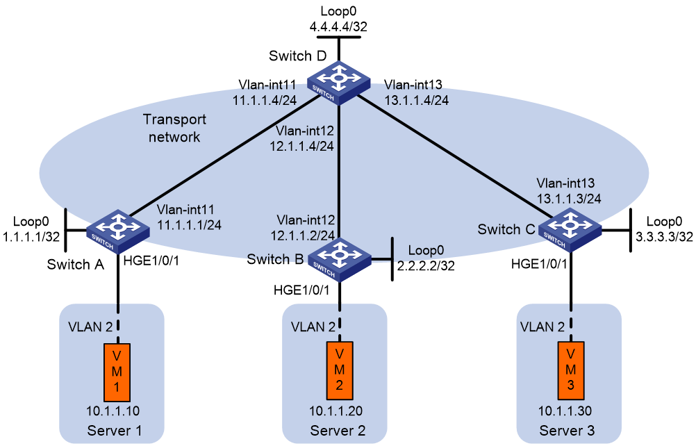
Network configuration
As shown in Figure 12, configure VXLAN 10 on Switch A, Switch B, and Switch C to provide connectivity for the VMs across the network sites.
Procedure
1. Configure IP addresses and unicast routing settings:
# Assign IP addresses to interfaces, as shown in Figure 12. (Details not shown.)
# Configure OSPF on all transport network switches (Switches A through D) for them to reach one another. (Details not shown.)
2. Configure Switch A:
# Enable L2VPN.
<SwitchA> system-view
[SwitchA] l2vpn enable
# Disable remote MAC address learning.
[SwitchA] vxlan tunnel mac-learning disable
# Create an EVPN instance on VSI vpna, and configure the switch to automatically generate an RD and a route target for the EVPN instance.
[SwitchA] vsi vpna
[SwitchA-vsi-vpna] evpn encapsulation vxlan
[SwitchA-vsi-vpna-evpn-vxlan] route-distinguisher auto
[SwitchA-vsi-vpna-evpn-vxlan] vpn-target auto
[SwitchA-vsi-vpna-evpn-vxlan] quit
# Create VXLAN 10.
[SwitchA-vsi-vpna] vxlan 10
[SwitchA-vsi-vpna-vxlan-10] quit
[SwitchA-vsi-vpna] quit
# Configure BGP to advertise BGP EVPN routes.
[SwitchA] bgp 200
[SwitchA-bgp-default] peer 4.4.4.4 as-number 200
[SwitchA-bgp-default] peer 4.4.4.4 connect-interface loopback 0
[SwitchA-bgp-default] address-family l2vpn evpn
[SwitchA-bgp-default-evpn] peer 4.4.4.4 enable
[SwitchA-bgp-default-evpn] quit
[SwitchA-bgp-default] quit
# On HundredGigE 1/0/1, create Ethernet service instance 1000 to match VLAN 2.
[SwitchA] interface hundredgige 1/0/1
[SwitchA-HundredGigE1/0/1] service-instance 1000
[SwitchA-HundredGigE1/0/1-srv1000] encapsulation s-vid 2
# Map Ethernet service instance 1000 to VSI vpna.
[SwitchA-HundredGigE1/0/1-srv1000] xconnect vsi vpna
[SwitchA-HundredGigE1/0/1-srv1000] quit
[SwitchA-HundredGigE1/0/1] quit
3. Configure Switch B:
# Enable L2VPN.
<SwitchB> system-view
[SwitchB] l2vpn enable
# Disable remote MAC address learning.
[SwitchB] vxlan tunnel mac-learning disable
# Create an EVPN instance on VSI vpna, and configure the switch to automatically generate an RD and a route target for the EVPN instance.
[SwitchB] vsi vpna
[SwitchB-vsi-vpna] evpn encapsulation vxlan
[SwitchB-vsi-vpna-evpn-vxlan] route-distinguisher auto
[SwitchB-vsi-vpna-evpn-vxlan] vpn-target auto
[SwitchB-vsi-vpna-evpn-vxlan] quit
# Create VXLAN 10.
[SwitchB-vsi-vpna] vxlan 10
[SwitchB-vsi-vpna-vxlan-10] quit
[SwitchB-vsi-vpna] quit
# Configure BGP to advertise BGP EVPN routes.
[SwitchB] bgp 200
[SwitchB-bgp-default] peer 4.4.4.4 as-number 200
[SwitchB-bgp-default] peer 4.4.4.4 connect-interface loopback 0
[SwitchB-bgp-default] address-family l2vpn evpn
[SwitchB-bgp-default-evpn] peer 4.4.4.4 enable
[SwitchB-bgp-default-evpn] quit
[SwitchB-bgp-default] quit
# On HundredGigE 1/0/1, create Ethernet service instance 1000 to match VLAN 2.
[SwitchB] interface hundredgige 1/0/1
[SwitchB-HundredGigE1/0/1] service-instance 1000
[SwitchB-HundredGigE1/0/1-srv1000] encapsulation s-vid 2
# Map Ethernet service instance 1000 to VSI vpna.
[SwitchB-HundredGigE1/0/1-srv1000] xconnect vsi vpna
[SwitchB-HundredGigE1/0/1-srv1000] quit
[SwitchB-HundredGigE1/0/1] quit
4. Configure Switch A:
# Enable L2VPN.
<SwitchC> system-view
[SwitchC] l2vpn enable
# Disable remote MAC address learning.
[SwitchC] vxlan tunnel mac-learning disable
# Create an EVPN instance on VSI vpna, and configure the switch to automatically generate an RD and a route target for the EVPN instance.
[SwitchB] vsi vpna
[SwitchB-vsi-vpna] evpn encapsulation vxlan
[SwitchB-vsi-vpna-evpn-vxlan] route-distinguisher auto
[SwitchB-vsi-vpna-evpn-vxlan] vpn-target auto
[SwitchB-vsi-vpna-evpn-vxlan] quit
# Create VXLAN 10.
[SwitchB-vsi-vpna] vxlan 10
[SwitchB-vsi-vpna-vxlan-10] quit
[SwitchB-vsi-vpna] quit
# Configure BGP to advertise BGP EVPN routes.
[SwitchC] bgp 200
[SwitchC-bgp-default] peer 4.4.4.4 as-number 200
[SwitchC-bgp-default] peer 4.4.4.4 connect-interface loopback 0
[SwitchC-bgp-default] address-family l2vpn evpn
[SwitchC-bgp-default-evpn] peer 4.4.4.4 enable
[SwitchC-bgp-default-evpn] quit
[SwitchC-bgp-default] quit
# On HundredGigE 1/0/1, create Ethernet service instance 1000 to match VLAN 2.
[SwitchC] interface hundredgige 1/0/1
[SwitchC-HundredGigE1/0/1] service-instance 1000
[SwitchC-HundredGigE1/0/1-srv1000] encapsulation s-vid 2
# Map Ethernet service instance 1000 to VSI vpna.
[SwitchC-HundredGigE1/0/1-srv1000] xconnect vsi vpna
[SwitchC-HundredGigE1/0/1-srv1000] quit
[SwitchC-HundredGigE1/0/1] quit
5. Configure Switch D:
# Establish BGP connections with other transport network switches.
<SwitchD> system-view
[SwitchD] bgp 200
[SwitchD-bgp-default] group evpn
[SwitchD-bgp-default] peer 1.1.1.1 group evpn
[SwitchD-bgp-default] peer 2.2.2.2 group evpn
[SwitchD-bgp-default] peer 3.3.3.3 group evpn
[SwitchD-bgp-default] peer evpn as-number 200
[SwitchD-bgp-default] peer evpn connect-interface loopback 0
# Configure BGP to advertise BGP EVPN routes, and disable route target filtering for BGP EVPN routes.
[SwitchD-bgp-default] address-family l2vpn evpn
[SwitchD-bgp-default-evpn] peer evpn enable
[SwitchD-bgp-default-evpn] undo policy vpn-target
# Configure Switch D as an RR.
[SwitchD-bgp-default-evpn] peer evpn reflect-client
[SwitchD-bgp-default-evpn] quit
[SwitchD-bgp-default] quit
Verifying the configuration
1. Verify the EVPN settings on Switch A:
# Verify that Switch A has advertised MAC/IP advertisement routes and IMET routes and received MAC/IP advertisement routes and IMET routes from Switch B and Switch C.
[SwitchA] display bgp l2vpn evpn
BGP local router ID is 1.1.1.1
Status codes: * - valid, > - best, d - dampened, h - history
s - suppressed, S - stale, i - internal, e - external
a - additional-path
Origin: i - IGP, e - EGP, ? - incomplete
Total number of routes from all PEs: 4
Route distinguisher: 1:10
Total number of routes: 6
Network NextHop MED LocPrf PrefVal Path/Ogn
* >i [2][0][48][0a00-2700-0010][0][0.0.0.0]/104
2.2.2.2 0 100 0 i
* >i [2][0][48][0a00-2700-0013][0][0.0.0.0]/104
3.3.3.3 0 100 0 i
* > [2][0][48][0a00-2700-0018][0][0.0.0.0]/104
0.0.0.0 0 100 32768 i
* > [3][0][32][1.1.1.1]/80
0.0.0.0 0 100 32768 i
* >i [3][0][32][2.2.2.2]/80
2.2.2.2 0 100 0 i
* >i [3][0][32][3.3.3.3]/80
3.3.3.3 0 100 0 i
# Verify that the VXLAN tunnel interfaces are up on Switch A. This step uses Tunnel 0 as an example.
[SwitchA] display interface tunnel 0
Tunnel0
Current state: UP
Line protocol state: UP
Description: Tunnel0 Interface
Bandwidth: 64 kbps
Maximum transmission unit: 1464
Internet protocol processing: Disabled
Last clearing of counters: Never
Tunnel source 1.1.1.1, destination 2.2.2.2
Tunnel protocol/transport UDP_VXLAN/IP
Last 300 seconds input rate: 134 bytes/sec, 1072 bits/sec, 1 packets/sec
Last 300 seconds output rate: 136 bytes/sec, 1088 bits/sec, 1 packets/sec
Input: 480 packets, 41764 bytes, 0 drops
Output: 480 packets, 42482 bytes, 0 drops
# Verify that the VXLAN tunnels have been assigned to the VXLAN.
[SwitchA] display l2vpn vsi verbose
VSI Name: vpna
VSI Index : 0
VSI State : Up
MTU : 1500
Bandwidth : Unlimited
Broadcast Restrain : Unlimited
Multicast Restrain : Unlimited
Unknown Unicast Restrain: Unlimited
MAC Learning : Enabled
MAC Table Limit : -
MAC Learning rate : -
Drop Unknown : -
Flooding : Enabled
Statistics : Disabled
VXLAN ID : 10
Tunnels:
Tunnel Name Link ID State Type Flood proxy
Tunnel0 0x5000000 UP Auto Disabled
Tunnel1 0x5000001 UP Auto Disabled
ACs:
AC Link ID State Type
HGE0/0/1 srv1000 0 Up Manual
# Verify that Switch A has created MAC entries for the VMs.
<SwitchA> display l2vpn mac-address
MAC Address State VSI Name Link ID/Name Aging
0a00-2700-0010 EVPN vpna Tunnel0 NotAging
0a00-2700-0013 EVPN vpna Tunnel1 NotAging
0a00-2700-0018 Dynamic vpna HGE0/0/1 Aging
--- 3 mac address(es) found ---
2. Verify that VM 1, VM 2, and VM 3 can communicate with one another. (Details not shown.)