- Table of Contents
- Related Documents
-
| Title | Size | Download |
|---|---|---|
| 01-Text | 6.73 MB |
Contents
Examining the installation site
2 Installing the device in a rack
Installing slide rails on the rack posts
Installing cage nuts for attaching mounting brackets
3 Installing removable components
Installing and removing interface modules
Removing the protective blank panel
Installing an interface module
Installing a filler panel in an empty interface module slot
Installing cable management brackets
Installing and removing fan trays
Installing and removing power supplies
(Optional) Installing transceiver modules
Installing a QSFP+/QSFP28 transceiver module
Connecting a QSFP+/QSFP28 cable
Viewing device startup information
1 Preparing for installation
ESD prevention
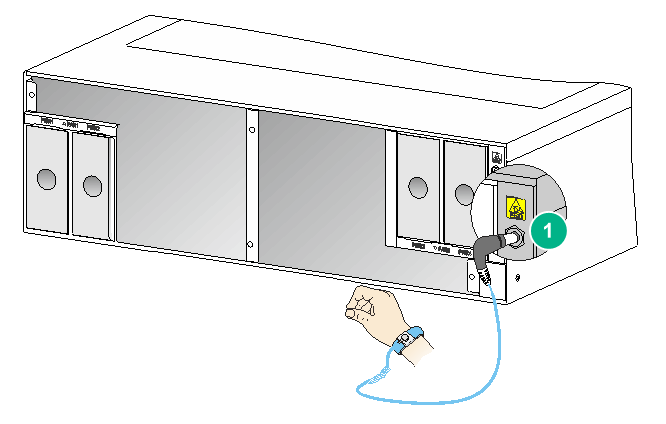
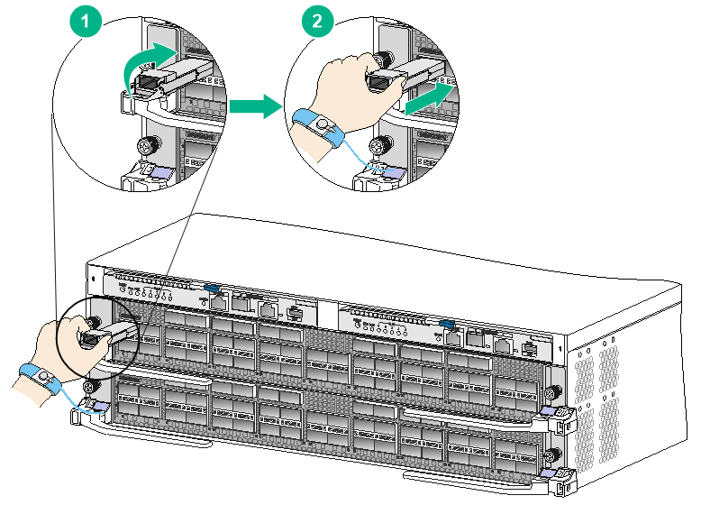
To prevent electrostatic discharge (ESD) damage, always wear an ESD wrist strap when working with the device or any component. Make sure the wrist strap makes good skin contact and is reliably grounded.
Figure 1-1 Attaching an ESD wrist strap
|
(1) ESD jack (with an ESD sign) |
Examining the installation site
The device must be used indoors. To ensure correct operation of the device and to prolong its service lifetime, the installation site must meet the load-bearing, temperature, humidity, cleanliness, EMI, grounding, power supply, ventilation, and space requirements. Reserve a minimum clearance of 1.2 m (3.94 ft) between the device and walls or other devices.
For more information, see H3C S12500R-2L Switch Router Installation Guide.
Installation tools
No installation tools are provided with the device. Prepare them yourself as required. Installation tools in Table 1-1 are for your reference.
|
Name |
Description |
|
ESD wrist strap |
|
|
Marker |
|
|
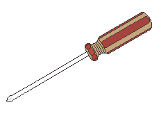
Phillips screwdriver |
|


2 Installing the device in a rack
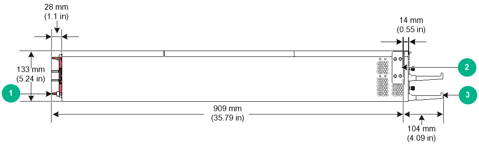
Device dimensions
Figure 2-1 Device dimensions
|
(1) Power supply handle |
(2) Mounting bracket |
|
(3) Cable management bracket |
|
Rack requirements
Table 2-1 Rack requirements
|
Device dimensions |
Rack requirements |
|
· Height—133 mm (5.24 in) (3 RU). · Width—440 mm (17.32 in). · Chassis depth—895 mm (35.24 in) · Total depth—1013 mm (39.88 in) ¡ 104 mm (4.09 in) from the rack-facing surface of the mounting brackets to the front ends of the cable management brackets ¡ 909 mm (35.79 in) from the rack-facing surface of the mounting brackets to the power supply handles at the chassis rear |
· A minimum of 1.1 m (3.61 ft) in depth (recommended) · A minimum of 130 mm (5.12 in) from the front rack post to the front door · A minimum of 950 mm (37.40 in) from the front rack post to the rear door |
|
|
NOTE: As a best practice, use a rack that has a single door at the front. |
Installing slide rails on the rack posts
Slide rail requirements
Table 2-2 Slide rail requirements
|
Max. chassis weight (fully configured) |
Applicable slide rails |
|
|
Slide rail model |
Adjustment range |
|
|
70 kg (154.32 lb) |
LSVM1BSR10 |
630 mm to 900 mm (24.80 in to 35.43 in) |
|
|
IMPORTANT: If you are not to use LSVM1BSR10 slide rails, use a tray with a load bearing capacity not less than 60 kg (132.28 lb) to support the device in the rack. |
Installing slide rails
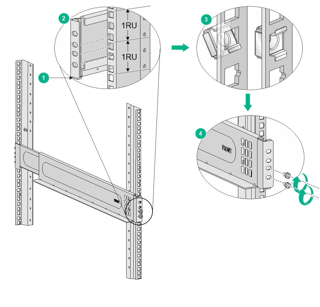
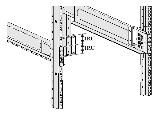
1. Read the signs on the slide rails to identify the front and rear ends of the slide rails.
2. Insert the locating pins at the bottom of the slide rails into the lowest square holes within the target 2U space on the rack posts. Make sure the four installation holes on each end of the slide rails align with the four square holes on the rack posts.
3. As shown in Figure 2-2, mark the cage nut installation holes on each rack post for installing the slide rails. Make sure the installation holes are at the same height on the four rack posts.
¡ On each front rack post, mark the lower three aligned square holes. The top aligned square hole will be blocked by the mounting bracket.
¡ On each rear rack post, mark the four aligned square holes.
4. Install cage nuts in the marked square holes on each rack post. See callout 3 in Figure 2-2.
5. Use M6 screws to secure the slide rails to the rack posts. The recommended torque for the M6 screws is 30 kgf-cm (2.94 Nm).
¡ On each front rack post, install M6 screws in the two lower cage nuts. The upper cage nut on each front rack post will be used for securing the mounting bracket.
¡ On each rear rack post, install M6 screws in all the four cage nuts.
Make sure the load-bearing surface of the slide rails is perpendicular to the rack posts.
Figure 2-2 Installing slide rails
|
(1) Locating pin |
(2) Mark the cage nuts installation holes |
|
(3) Install cage nuts in the marked square holes |
|
|
(4) Use the provided M6 screws to secure the slide rails to the rack posts |
|
Installing cage nuts for attaching mounting brackets
1. As shown in Figure 2-3, determine the cage nut installation holes and then mark them on the front rack post.
2. Install cage nuts in the marked square holes on the front rack posts. If you have installed screws in the marked holes, remove them first.
Figure 2-3 Installing cage nuts
Mounting the device in a rack
|
|
CAUTION: · Hold the chassis handles to move the device. Do not hold the handle of a fan tray, a power supply, or a module to move the device. Any attempt to carry the device with these parts might cause equipment damage or even bodily injury. · After you place the device on the slide rails, do not leave go of your hands immediately because this might tip the device, damaging the device or even causing bodily injury. · Do not place your hand into any slot when you move the chassis. |
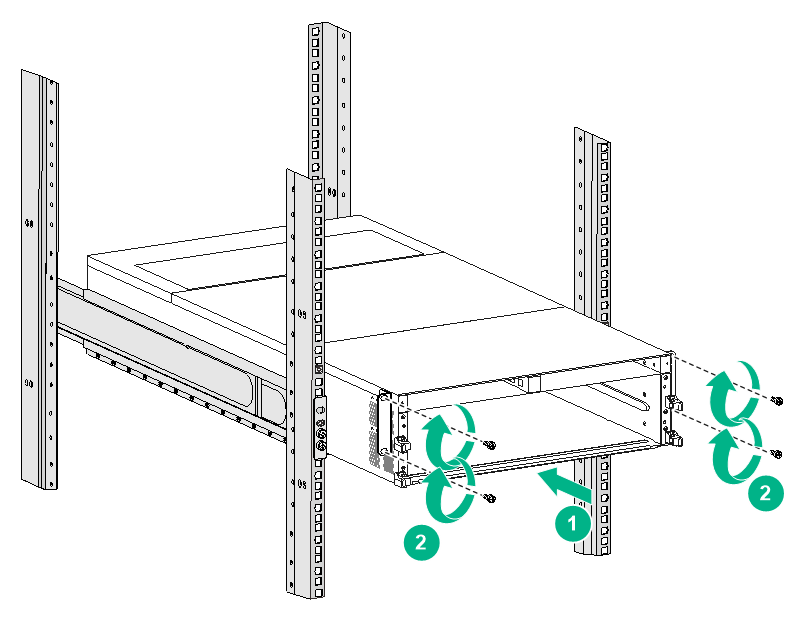
To mount the device in the rack:
1. Face the rear of the chassis towards the front of the rack.
2. Move the device by holding the chassis handles.
3. Place the device on the slide rails from the front of the rack and slide the device along the guide rails until the mounting brackets on the device touch the front rack posts tightly, as shown by callout 1 in Figure 2-4.
4. Use the provided M6 screws provided with the device to attach the mounting brackets to the rack posts. The recommended torque for the M6 screws is 30 kgf-cm (2.94 Nm).
If the mounting holes in the mounting brackets cannot align with the cage nuts on the rack, verify that the cage nuts are installed correctly. For cage nut installation, see "Installing cage nuts for attaching mounting brackets".
Figure 2-4 Mounting the device in the rack
|
(1) Slide the chassis into the rack |
|
(2) Use the provided M6 screws to secure the mounting brackets to the rack |
Grounding the device
|
|
CAUTION: · Grounding the device reliably is crucial to lightning protection and EMI protection. Ground the device reliably before you use it. · Use the grounding cable (yellow-green grounding cable) provided with the device. · Connect the grounding cable to the grounding point on the rack or a grounding strip in the equipment room. Do not connect it to a fire main or lightning rod. |
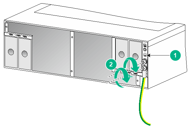
To ground the device:
1. Unpack the grounding cable.
The grounding cable provided with the device is compliant with the NEBS standards. The two-hole grounding lug of the grounding cable is used for connecting the chassis. The ring terminal of the grounding cable is used for connecting the grounding strip.
2. Remove the two M6 grounding screws from the grounding holes at the rear of the chassis.
A grounding sign is provided with the grounding holes, as shown by callout 1 in Figure 2-5.
3. Use M6 grounding screws to attach the two-hole grounding lug of the grounding cable to the chassis.
The recommended torque for M6 grounding screws is 30 kgf-cm (2.94 Nm).
4. Connect the other end of the grounding cable to the grounding point on the rack or a grounding strip in the equipment room.
Figure 2-5 Connecting the grounding cable
|
(1) Grounding sign |
(2) Use grounding screws to attach the two-hole grounding lug to the grounding point |
3 Installing removable components
This section describes the installation procedures for the supervisor engine units (SEUs, also called MPUs), interface modules, fan trays, and power supplies. For the removable components available for the device, see H3C S12500R-2L Switch Router Installation Guide.
|
|
WARNING! Long-time exposure to strong air flow might cause discomfort. As a best practice, do not stand close to the air outlet vents while the device is operating. If you must be next to the device on the air outlet vent side for an extended period, avoid the air flow or take other protective measures. |
|
|
CAUTION: For good ventilation of the device, install filler panels in the empty module and power supply slots. |
Attaching an ESD wrist strap
To prevent ESD damage, always wear an ESD wrist strap when working with any component of the device. Make sure the wrist strap makes good skin contact and is reliably grounded. See Figure 1-1 for attaching an ESD wrist strap.
Installing and removing SEUs
|
|
CAUTION: · If you are not to install an SEU in an SEU slot, keep the filler panel in the slot. · When you install an SEU, avoid damaging the connectors on the SEU. |
You can install one SEU, or two SEUs for redundancy on the device. If you are to install one SEU, install it in either of the SEU slots.
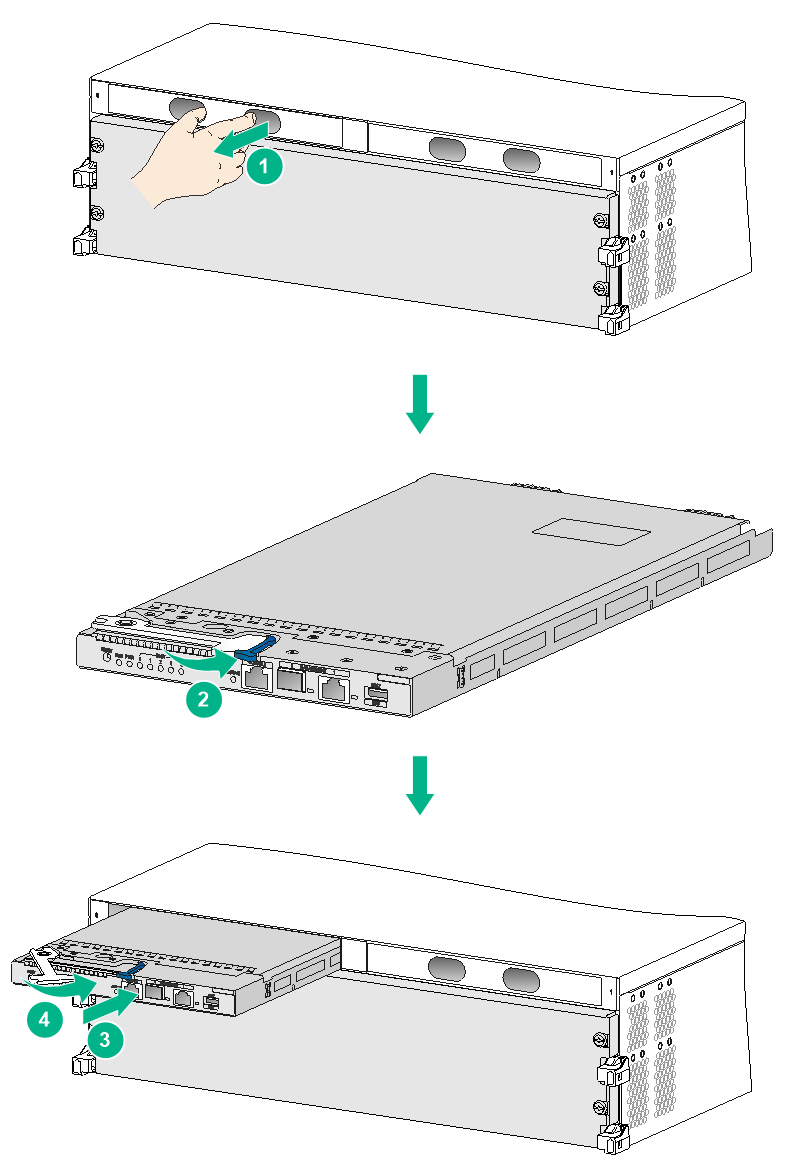
Installing an SEU
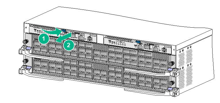
1. As shown by callout 1 in Figure 3-1, remove the filler panel from the target SEU slot.
Keep the removed filler panel secure for future use.
2. As shown by callout 2 in Figure 3-1, press the latch on the SEU to release the ejector lever. Rotate outward the ejector lever to the outmost.
3. As shown by callout 3 in Figure 3-1, orient the SEU with the upside up. Hold the SEU by the front panel with one hand and support the bottom with the other. Push the SEU steadily into the slot along the guide rails until it has firm contact with the slot.
Keep the SEU parallel to the slot to avoid touching other components in the chassis.
4. As shown by callout 4 in Figure 3-1, rotate inward the ejector lever until the latch locks the ejector lever in place.
Removing an SEU
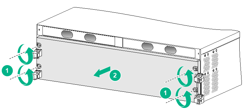
1. As shown by callout 1 in Figure 3-2, press the latch to release the ejector lever.
2. Hold the ejector lever to pull the SEU part way out of the slot. See callout 2 in Figure 3-2.
3. Holding the SEU by the front panel with one hand and supporting the bottom with the other, pull the SEU steadily out of the slot along the guide rails.
Keep the SEU parallel to the slot to avoid touching other components in the chassis.
Installing and removing interface modules
Removing the protective blank panel
|
|
WARNING! The protective blank panel is heavy. To avoid bodily injury, use both hands to remove it. |
The device comes with a protective blank panel installed over the interface module slots to protect the device from damage during shipment.
To remove the protective blank panel:
1. Remove the screws that secure the protective blank panel to the device. See callout 1 in Figure 3-3.
2. As shown by callout 2 in Figure 3-3, remove the protective blank panel with both hands.
Keep the removed protective blank panel and screws secure for future use.
Figure 3-3 Removing the protective blank panel
Installing an interface module
The ejector levers of the interface modules and the ejector lever pillow blocks have purple marks.
To install an interface module:
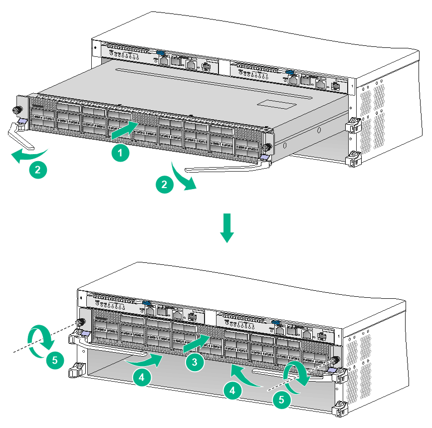
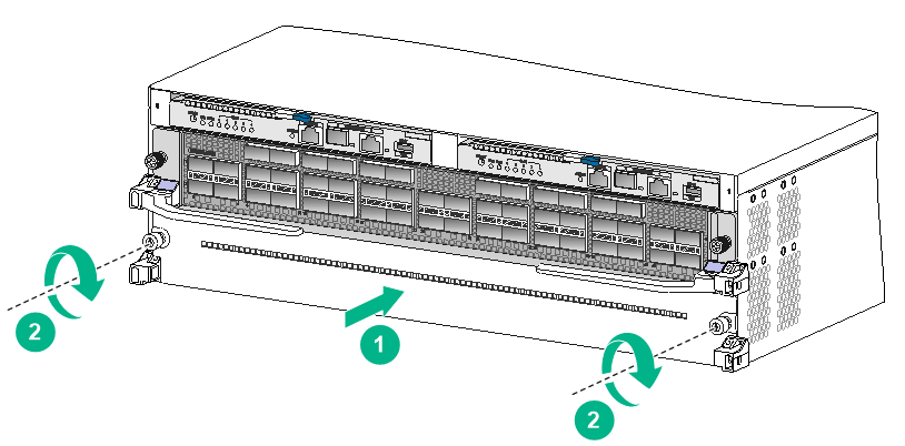
1. Orient the interface module with the lettering on it upward.
2. As shown by callout 1 in Figure 3-4, hold the interface module by the front panel with one hand and support its bottom with the other. Slide the interface module steadily into the target slot along the guide rails.
Keep the interface module parallel to the slot to avoid touching other components in the chassis.
3. As shown by callout 2 in Figure 3-4, fully open the ejector levers when most of the interface module is inserted into the slot.
4. Push the interface module until the brakes on the ejector levers touch the slot edges tightly.
5. As shown by callout 3 in Figure 3-4, continue to push the interface module by its middle part on the front panel until you cannot move it.
6. As shown by callout 4 in Figure 3-4, push the ejector levers inward until they come in close contact with the panel.
7. As shown by callout 5 in Figure 3-4, fasten the captive screws to secure the interface module to the chassis.
The recommended torque for the captive screws is 5 kgf-cm (0.49 Nm).
Figure 3-4 Installing an interface module
Removing an interface module
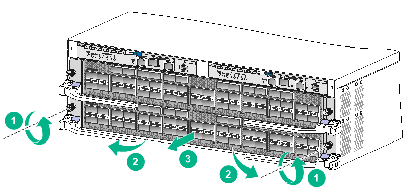
1. As shown by callout 1 in Figure 3-5, loosen the captive screws on the interface module
2. As shown by callout 2 in Figure 3-5, open the ejector levers fully.
3. As shown by callout 3 in Figure 3-5, pull the interface module part way out of the slot. Holding the interface module by the front panel with one hand and supporting the bottom with the other, pull the interface module steadily out of the slot along the guide rails.
To avoid touching other components in the chassis, keep the interface module parallel to the slot while pulling it out.
Figure 3-5 Removing an interface module
Installing a filler panel in an empty interface module slot
An interface module slot filler panel is provided with the device. If you are not to install an interface module in an interface module slot, install the filler panel in the slot.
To install a filler panel in an empty interface module slot:
1. As shown by callout 1 in Figure 3-6, align the two captive screws on the filler panel with the installation holes on the slot.
2. As shown by callout 2 in Figure 3-6, fasten the captive screws on the filler panel.
The recommended torque is 5 kgf-cm (0.49 Nm).
Figure 3-6 Installing the filler panel in an empty interface module slot
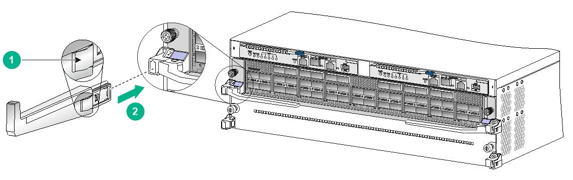
Installing cable management brackets
|
|
CAUTION: To avoid device damage, press the spring tab when you remove a cable management bracket. |
The cable management brackets are installed on the two sides of the interface module slots. As a best practice, install cable management brackets after you have installed interface modules.
As shown in Figure 3-7, insert the cable management bracket end that has a spring tab into the cable management bracket hole until the bracket has close contact with the hole.
Figure 3-7 Installing a cable management bracket
|
(1) Spring tab on the cable management bracket |
|
(2) Align the cable management bracket with the bracket hole |
Installing and removing fan trays
Follow these restrictions and guidelines when you install a fan tray:
· The device has two fan tray slots: FAN1 and FAN2. Install two fan trays on the device.
· To prevent dust from entering the chassis, keep the fan trays in position if the device is not in use.
· The fan tray is hot swappable. Follow these guidelines when you hot swap a fan tray:
¡ Ensure electricity safety.
¡ Replace a fan tray only when the other fan tray is operating correctly.
¡ To prevent dust from entering the chassis, keep the failed fan tray in position before the replacement.
· To install a fan tray in slot FAN1, orient the fan tray so that the LED is on the left side of the front panel. To install a fan tray in slot FAN2, orient the fan tray so that the LED is on the right side of the front panel.
· To avoid damaging the fan tray, use both hands when installing or removing a fan tray.
· When you hot swap a fan tray, only one fan tray is operating and it automatically increases the fan rotation speed and makes louder noise. Take protection measures such as wearing an earmuff or earplug. In addition, make good preparation before the hot swapping to minimize the operation time.
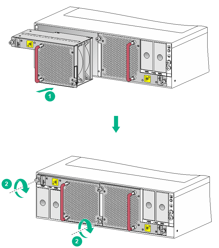
Installing fan trays
The following procedure installs a fan tray in the FAN1 slot:
1. Unpack the fan tray.
2. Orient the fan tray correctly. Align the fan tray with the fan tray slot.
3. Holding the fan tray handle with one hand and supporting the bottom of the fan tray with the other, insert the fan tray part way into the slot, as shown by callout 1 in Figure 3-8.
Keep the fan tray as steady as possible while inserting it into the slot.
4. Squeezing the captive screw at the air vents side with one hand and holding the fan tray handle with the other, push the fan tray fully into the slot.
5. Fasten the captive screws on the fan tray.
The recommended torque for the captive screws is 5 kgf-cm (0.49 Nm).
Figure 3-8 Installing a fan tray
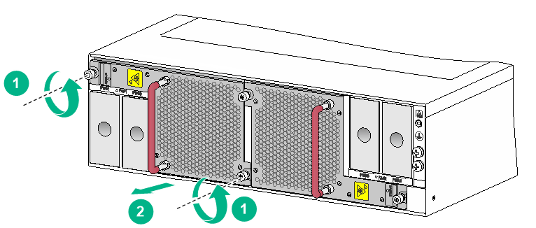
Removing a fan tray
The following procedure removes the fan tray from the FAN1 slot:
1. As shown by callout 1 in Figure 3-9, loosen the captive screws on the fan tray.
2. Squeezing the captive screw at the air vents side with one hand and holding the fan tray handle, pull the fan tray outward until it is disengaged from the chassis. Remove the fan tray after the fan stops rotating.
Figure 3-9 Removing a fan tray
Installing and removing power supplies
Installing a power supply
|
|
CAUTION: The device comes with a filler panel in each power supply slot. If you are not to install a power supply in a slot, install a filler panel in the slot to prevent dust from entering the chassis. |
The installation procedure is the same for AC and DC power supplies. The following procedure installs an AC power supply.
To install a power supply:
1. Remove the filler panel from the target power supply slot. As shown by callout 1 in Figure 3-10, put your forefinger into the hole of the filler panel and pull the filler panel out of the slot along the guide rails.
2. As shown by callout 2 in Figure 3-10, holding the power supply handle with one hand and supporting the power supply bottom with the other, slide the power supply along the guide rails into the slot until the latch locks the power supply in place.
Figure 3-10 Installing a power supply
Removing a power supply
|
|
CAUTION: Before removing a power supply, disconnect the power cord from it. |
The removal procedure is the same for AC and DC power supplies. The following procedure removes an AC power supply.
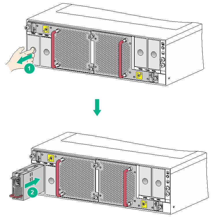
To remove a power supply:
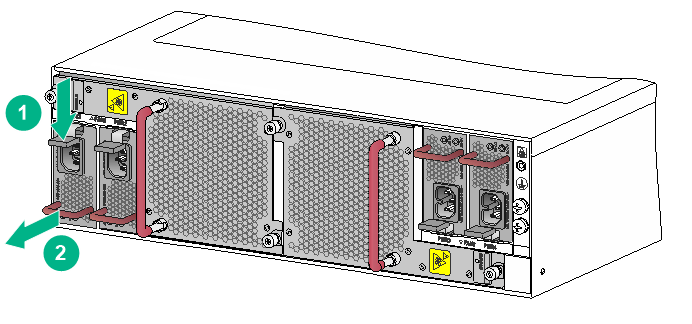
1. Hold the handle on the power supply with one hand and pull downward the latch. See callout 1 in Figure 3-11.
2. Pull the power supply part out of the slot. Holding the bottom of the power supply with the other hand, pull the power supply out of the slot slowly. See callout 2 in Figure 3-11.
Figure 3-11 Removing a power supply
Connecting the power cord
|
|
CAUTION: · Power on the device after you have completed installation. · Prepare a separate circuit breaker for power input of each power cord. · Turn off the circuit breaker before you connect the power cord. |
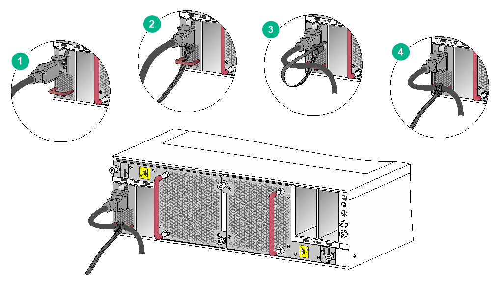
Connecting the AC power cord
1. Plug the AC power cord connector into the AC input receptacle of the power supply.
2. Use a removable cable tie or self-adhesive cable tie (provided with the power supply) to secure the power cord to the handle of the power supply.
3. Connect the other end of the power cord to an AC power source.
Figure 3-12 Using a removable cable tie to secure the power cord to the device
Connecting the DC power cord
|
|
WARNING! · Before connecting the DC power cord, make sure the circuit breakers for both the positive lead (+) and the negative lead (–) are turned off. · To avoid electrical shock, a plastic cover is installed over the terminal blocks. Remove the cover when you connect the DC power cord and install the cover in time after you connect the DC power cord. |
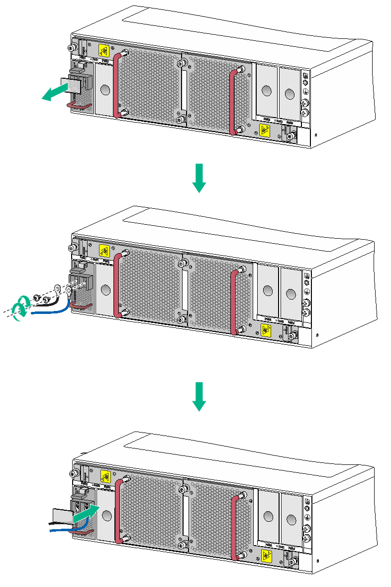
To connect the DC power cord:
1. Remove the plastic cover over the wiring terminals, and use a Phillips screwdriver to remove the M5 screws.
The recommended torque is 20 kgf-cm (1.96 Nm).
2. Connect the wire marked with the negative polarity symbol (–) to the negative terminal (–) on the power supply. Connect the wire marked with the positive polarity symbol (+) to the positive terminal (+) on the power supply.
3. Fasten the M5 screws to secure the wires and then install the plastic cover.
4. Connect the other end of the power cord to a DC power source.
5. Examine the input status LED (IN OK) on the power supply. If the LED is green, the power cord is successfully connected. If the LED is off, examine the installation, troubleshoot the problems, and try again until the LED is on.
Figure 3-13 Connecting the DC power cord
(Optional) Installing transceiver modules
|
|
CAUTION: To prevent particles from entering the ports, install the dust plugs that come with the interface modules in the QSFP+/QSFP28 ports if you are not to install transceiver modules or cables in the ports. |
Installing a QSFP+/QSFP28 transceiver module
|
|
CAUTION: · Read the following instructions before you install a QSFP+/QSFP28 transceiver module. Failure to follow these instructions might cause damage to the module. · Do not remove the dust plug from the QSFP+/QSFP28 transceiver module if you are not to connect an optical fiber to the module. · Before you install a QSFP+/QSFP28 transceiver module, remove the optical fiber (if any) from it. |
To install a QSFP+/QSFP28 transceiver module:
1. Unpack the module.
Do not touch the golden plating of the module.
2. Pivot the clasp of the module up. Holding the module, gently push the module into the slot until it has firm contact with the slot, as shown in Figure 3-14.
¡ For a module that uses a plastic pull latch, skip this step.
¡ If you cannot hold the module by its two sides because of high module density, press the module on its head end to push it in.
Figure 3-14 Installing a QSFP+/QSFP28 module
Connecting a QSFP+/QSFP28 cable
|
|
CAUTION: When you connect a fiber cable, make sure the bend radius of the cable is not less than eight times the fiber diameter. |
The cables are hot swappable.
Use QSFP+ cables to connect QSFP+ ports and QSFP28 cables to connect QSFP28 ports.
To connect a QSFP+/QSFP28 cable:
1. Unpack the cable.
2. Plug the cable connector into the port. Make sure the cable connector is correctly oriented.
4 Cabling recommendations
Routing network cables
The cable management brackets are installed on the two sides of the interface module section. As a best practice, route network cables from the left and right sides.
Routing power cords
When you route power cords, take consideration of the layout of the equipment room, including the locations of the power distribution cabinet, AC power receptacles, and lightning protection box. Ensure safety when routing power cords.
The power supplies of the device are located on the far left and far right of the rear panel. As a best practice, route power cords for the left power supplies from left of the device and route power cords for the right power supplies from right of the device.
5 Accessing the device
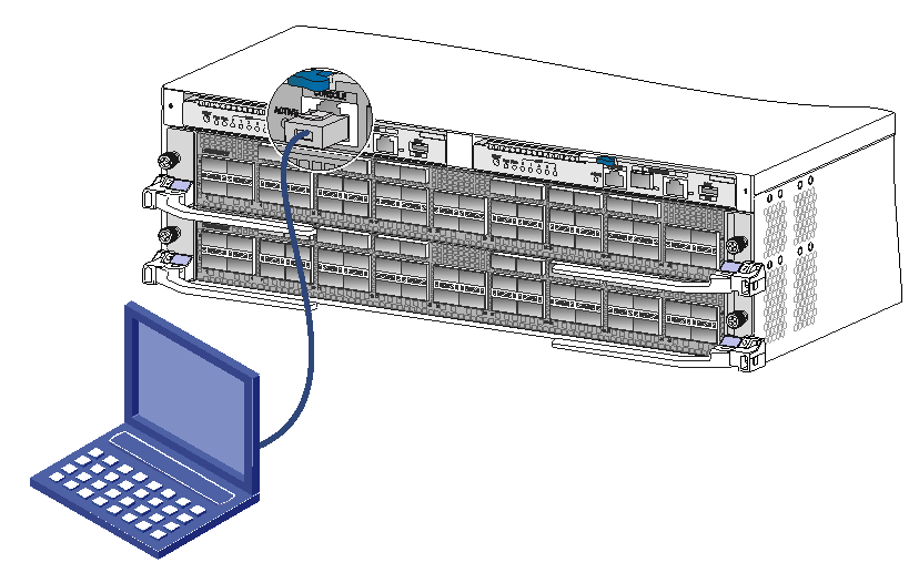
The first time you access the device, you can only log in to the device through the console port. Use a console cable to connect a console terminal, for example, a PC, to the console port on the device.
Connecting the console cable
|
|
IMPORTANT: · Identify the mark on the console port and make sure you are connecting to the correct port. · The serial ports on PCs do not support hot swapping. If the device has been powered on, connect the console cable to the PC before connecting to the device, and when you disconnect the cable, first disconnect from the device. |
To connect the console cable:
1. Plug the DB-9 female connector of the console cable to the serial port of the PC.
2. Plug the RJ-45 connector of the console cable to the console port of the device.
Figure 5-1 Connecting a terminal to the console port
Verification before login
Before you log in to the device, perform the following tasks:
· Verify that the device has been correctly installed.
· Verify that all modules have been correctly installed.
· Verify that all the network cables, fibers, power cord, and grounding cables have been correctly connected.
· Verify that the voltage of the power source is as required.
· Verify that the console cable has been correctly connected, the terminal or PC used for configuration has started, and the configuration parameters have been set.
· Verify that the device has been powered on.
Viewing device startup information
After the device is powered on, the configuration terminal output startup information. The output information varies by software versions.
The following shows a sample output you will see when the device starts up:
System is Starting....
Press Ctrl+D to access BASIC-BOOTWARE MENU
Press Ctrl+T to access BOOTWARE DIAG-TEST MENU
Booting Normal Extend Bootware
[Warning]Use default bootware config!
****************************************************************************
* *
* BootWare, Version 1.02 *
* *
****************************************************************************
Copyright (c) 2004-2020 New H3C Technologies Co., Ltd.
Compiled Date : Jul 4 2019
Memory Type : DDR4 SDRAM
Memory Size : 16384MB
Memory Speed : 2133MHz
flash Size : 7296MB
CPLD 1 Version : 0.0
CPLD 2 Version : 0.0
CPLD 3 Version : 0.0
PCB Version : Ver.A
BootWare Validating...
Press Ctrl+B to access EXTENDED-BOOTWARE MENU...
Loading the main image files...
Loading file flash:/SYSTEM.bin..............................................
............................................................................
............................................................................
....................................Done.
Loading file flash:/BOOT.bin................................................
............................................................................
............................................................................
............................................................................
................Done.
Image file flash:/BOOT.bin is self-decompressing............................
............................................................................
.............................................Done.
System image is starting...
Line aux1/0 is available.
Press ENTER to get started.
Press Enter at the prompt. When the prompt <Sysname> appears, you can configure the device.
After the device finishes startup, verify the following items:
· The cooling system is working, and you can hear fan rotating noise and feel air being blown out.
· The LEDs on the SEU show that the system is operating correctly. For more information about LEDs, see H3C S12500R-2L Switch Router Installation Guide.