- Table of Contents
- Related Documents
-
| Title | Size | Download |
|---|---|---|
| 01-Text | 1.49 MB |
Determining the installation position
Connecting the AP to the network
Verifying network connectivity when the AP operates as a fit AP
Verifying network connectivity when the AP operates as a fat AP
Logging in to the fat AP through the console port
Setting up the configuration environment
Logging in to the AP through Telnet or the Web interface
1 Preparing for installation
Safety recommendations
|
|
WARNING! Only professional technical personnel can install and remove the AP and its accessories. You must read all safety instructions carefully before working with the AP. |
To avoid possible bodily injury and equipment damage, read the following safety recommendations before installing the AP. Note that the recommendations do not cover every possible hazardous condition.
· To avoid bodily injury and device damage, take adequate safety measures.
· Place the AP in a dry and flat location and take anti-slip measures.
· Keep the AP clean and dust-free.
· Do not place the AP in a moist area and avoid liquid intrusion.
· Keep the AP and installation tools away from walkways.
Site preparation
Before installing the AP, examine the installation site and make sure the AP will operate in a favorable environment. Make sure the temperature and humidity at the installation site meet the requirements in Table1-1.
Table1-1 Temperature and humidity requirements
|
Item |
Specification |
|
Operating temperature |
–10°C to +55°C (–14°F to +131°F) |
|
Storage temperature |
–40°C to +70°C (–40°F to +158°F) |
|
Operating humidity |
5% RH to 95% RH, noncondensing |
Installation accessories
Figure1-1 Installation accessories
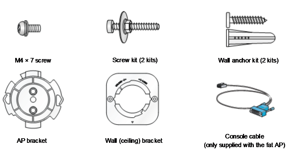
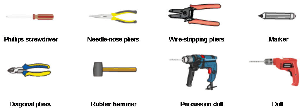
Installation tools
When installing the AP, you might need the following tools. Prepare the installation tools yourself as required.
Figure1-2 Installation tools
2 Installing the AP
Installation flowchart
Figure2-1 Installation flowchart

Pre-installation tasks
Before installing the AP, perform the following tasks:
· Power on the AP and connect the AP to the network. Examine the LEDs to verify that the AP is operating correctly. For information about the LEDs, see "LEDs."
· Record the MAC address and serial number of the AP for future use.
Determining the installation position
Determine the installation position by observing the following principles:
· As few obstacles (for example, walls) as possible exist between the AP and clients.
· The AP is far away from electronic devices (such as microwave oven) that might generate radio frequency (RF) noise.
· The AP does not hinder people’s daily work and life.
· The place is not water seeping, water soaking, and condensing.
Mounting the AP
The AP can be installed only indoors. You can mount the AP on a wall or on a ceiling.
Mounting brackets
The AP comes with an AP bracket and a wall (ceiling) bracket. To mount the AP on a wall or a ceiling, attach the AP bracket to the AP, and attach the wall (ceiling) bracket to the wall or ceiling.
Figure2-2 Installation holes on the wall (ceiling) bracket

Figure2-3 AP bracket and wall (ceiling) bracket
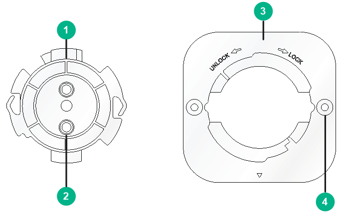
|
(1) AP bracket |
(2) Guide pin |
|
(3) Wall (ceiling) bracket |
(4) Installation hole |
Mounting the AP on a wall
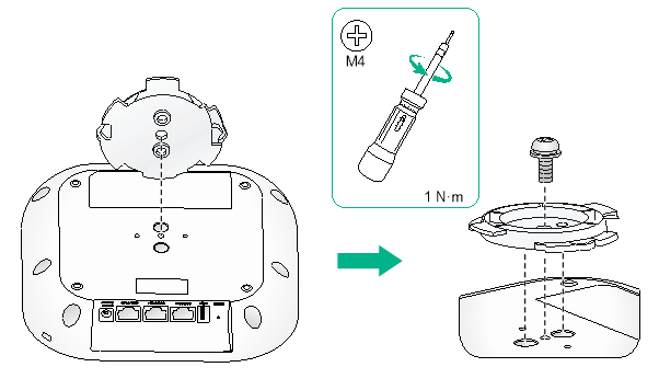
1. Align the guide pins on the AP bracket with the guide holes in the AP, and use the M4 × 7 screw to attach the AP bracket to the AP.
Figure2-4 Attaching the AP bracket to the AP
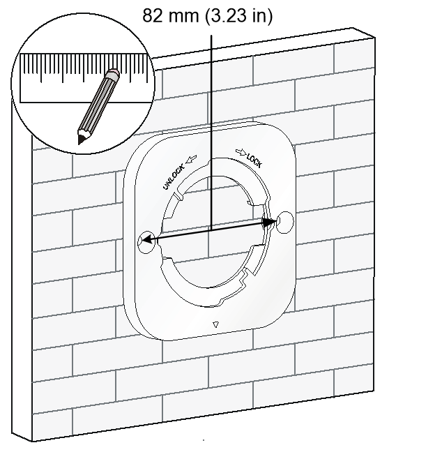
2. Mark the installation holes on the wall by using the wall bracket.
Figure2-5 Marking the installation holes on the wall
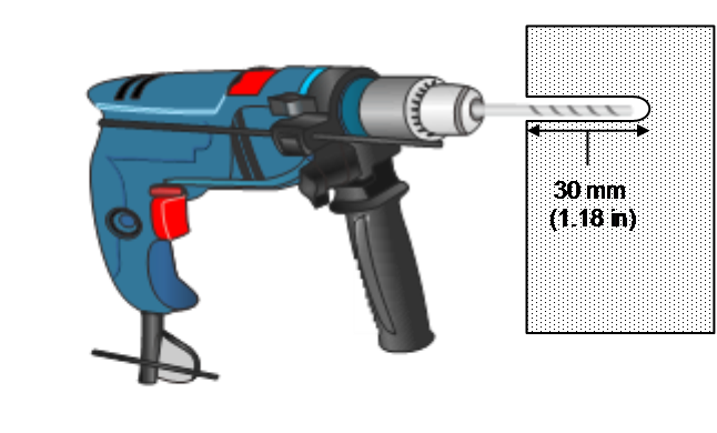
3. Drill two holes with a diameter of 6 mm (0.24 in) and a depth of 30 mm (1.18 in) in the marked locations.
Figure2-6 Drilling holes in the wall
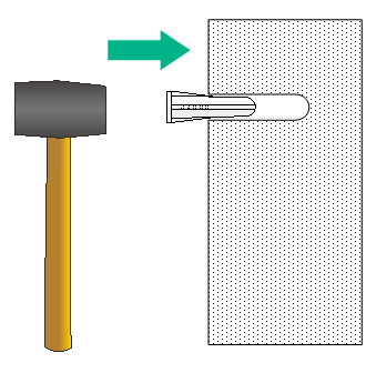
4. Insert a screw anchor into each hole, and tap the screw anchor by using a rubber hammer until it is all flush with the wall surface.
Figure2-7 Hammering wall anchors into holes
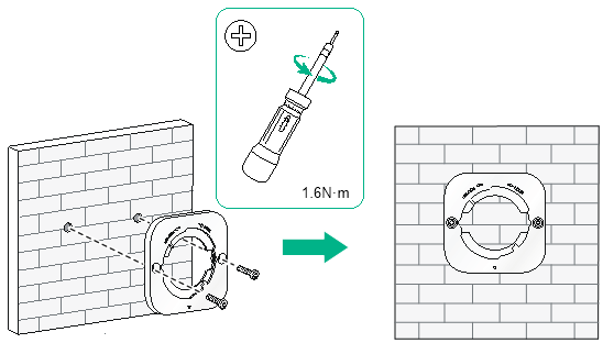
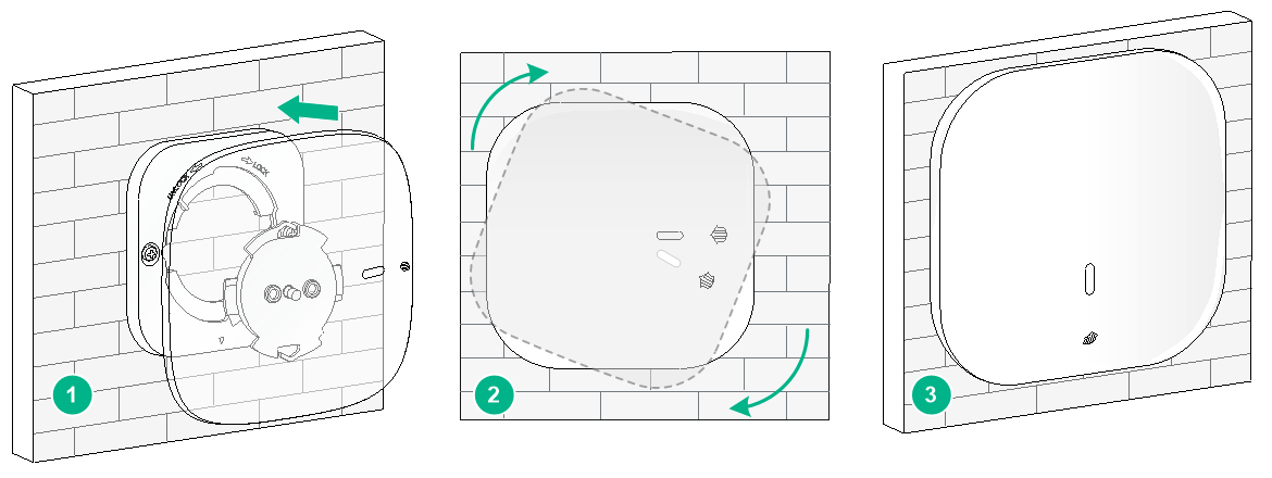
5. Align the installation holes in the wall bracket with the holes in the wall, and use screws to attach the wall bracket to the wall.
Figure2-8 Attaching the wall bracket to the wall
6. Align the AP with the wall bracket in the direction as shown Figure2-9, and rotate the AP clockwise until it clicks into place.
Figure2-9 Attaching the AP to the wall bracket
Mounting the AP on a ceiling
|
|
CAUTION: The ceiling for installing the AP must be less than 18 mm (0.71 in) in thickness, and can bear a load of 5 kg (11.02 lb). If the ceiling is not strong enough, use boards to reinforce the ceiling as a best practice. |
To mount the AP on a ceiling:
1. Align the guide pins on the AP bracket with the guide holes in the AP, and use a M4 × 7 screw to attach the AP bracket to the AP, as shown in Figure2-4.
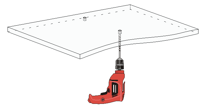
2. Remove the ceiling tile and use the ceiling bracket to mark the installation holes on the ceiling tile. Drill two holes with a diameter of 5 mm (0.20 in) in the marked positions.
Figure2-10 Drilling holes in the ceiling tile
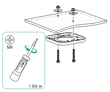
3. Thread pan-head screws through the installation holes in the ceiling bracket and into the holes in the ceiling. Fasten washers and nuts at the other side of the ceiling to attach the mounting bracket to the ceiling.
Figure2-11 Attaching the ceiling bracket to the ceiling
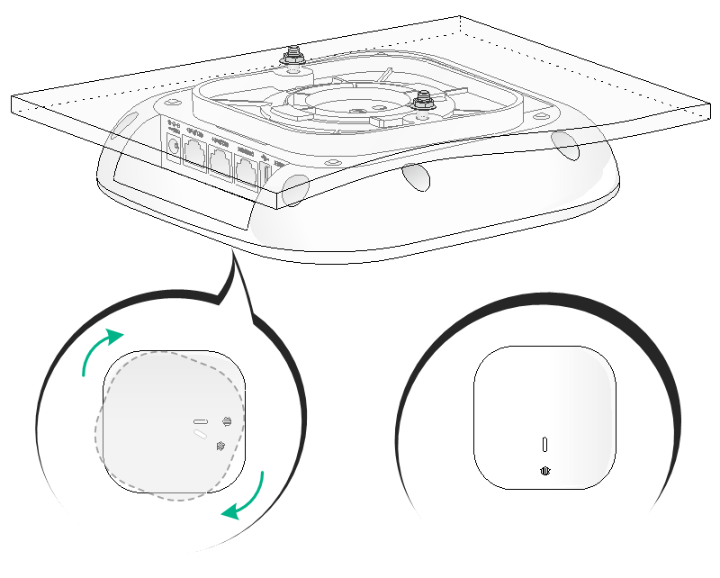
4. Align the AP with the ceiling bracket in the direction as shown in Figure2-12, and rotate the AP clockwise until it clicks into place.
|
|
CAUTION: Verify that the AP is securely seated over the ceiling bracket. |
Figure2-12 Attaching the AP to the ceiling bracket
Powering on the AP
You can supply power to the AP by using a power adapter or through 802.3at-compliant PoE.
Prerequisites
Make sure the local power source or PSE is reliably grounded.
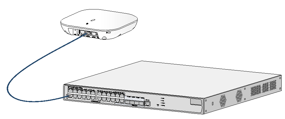
Connecting the PoE power supply
Use an Ethernet cable to connect an Ethernet port on the AP to a port on a switch that supports PoE.
Figure2-13 Connecting the PoE power supply
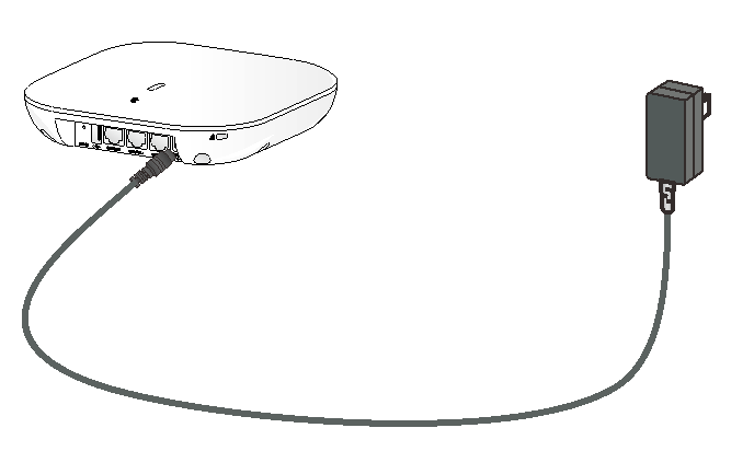
Connecting a power adapter
Use a power adapter to connect the AP to a local power source. The AP does not come with a power adapter. Purchase one as needed.
Table2-1 describes the power adapter specifications.
Table2-1 Power adapter specifications
|
Item |
Specifications |
|
Power input |
100 V to 240 VAC |
|
Power output |
48 VDC |
Figure2-14 Connecting the AP to a local power source by using a power adapter
Verifying the connection
After connecting the AP to a power source, examine the AP LED to verify the connection. For more information about the AP LED, see "LEDs."
Connecting the AP to the network
Verifying network connectivity when the AP operates as a fit AP
All AP settings are configured on the AC when the AP operates as a fit AP. Execute the display wlan ap all command on the AC. If the AP status is R/M, the AP has been connected to the network.
<AC> display wlan ap all
Total number of APs: 1
Total number of connected APs: 1
Total number of connected manual APs: 1
Total number of connected auto APs: 0
Total number of connected common APs: 1
Total number of connected WTUs: 0
Total number of inside APs: 0
Maximum supported APs: 512
Remaining APs: 511
Total AP licenses: 128
Local AP licenses: 127
Server AP licenses: 0
Remaining local AP licenses: 127
Sync AP licenses: 01
AP information
State : I = Idle, J = Join, JA = JoinAck, IL = ImageLoad
C = Config, DC = DataCheck, R = Run M = Master, B = Backup
AP name APID State Model Serial ID
ap1 1 I WA5530 219801A0YF9167G00000
Verifying network connectivity when the AP operates as a fat AP
Ping the uplink network device from the fat AP. If the ping operation succeeds, the AP has been connected to the network.
3 Logging in to the fat AP
Typically, the AP is installed at a high position. As a best practice, log in to the AP and configure settings before installing the AP.
You can log in to the fat AP through the console port, Telnet, or Web interface.
Logging in to the fat AP through the console port
Logging in through the console port requires the following items:
· Console cable—An eight-core shielded cable with a crimped RJ-45 connector at one end and a DB-9 connector at the other.
· Configuration terminal—A PC or a data terminal that has an RS-232 interface.
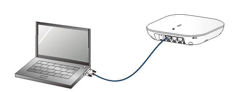
Setting up the configuration environment
|
|
IMPORTANT: · To connect a PC to a switch, first connect the PC end as a best practice. To disconnect a PC from a switch, first disconnect the switch end as a best practice. · If the PC does not have an RS-232 interface but has a USB port, you can use a USB-to-RS232 converter and install the RS232 driver. |
As shown in Figure3-1, connect the DB-9 connector of the console cable to the configuration terminal, and then connect the RJ-45 connector to the console port on the AP.
Figure3-1 Connecting the console cable
Setting terminal parameters
To configure and manage the AP through the console port, you must run a terminal emulator program, Super Terminal or PuTTY, on your PC. You can use the emulator program to connect a network device, a Telnet site, or an SSH site. For more information about the terminal emulator programs, see the user guides for these programs.
The following are the required terminal settings:
· Bits per second—9,600.
· Data bits—8.
· Stop bits—1.
· Parity—None.
· Flow control—None.
Powering on the AP
After the console cable is correctly connected, power on the AP. The following AP startup information will be displayed on the configuration terminal:
System is starting...
Booting Normal Extend BootWare.
……
System application is starting...
Startup configuration file does not exist.
User interface con0 is available.
Press ENTER to get started.
At the prompt, press Enter to configure the AP.
Logging in to the AP through Telnet or the Web interface
Telnet and Web access are enabled by default. The default username, password, and management IP address of VLAN-interface 1 are admin, h3capadmin, 192.168.0.50/24, respectively.
If the IP address has been changed, please contact your network administrator to obtain the new IP address.
4 Appendix A Technical specifications
The H3C WA5530 can operate as a fit AP or a fat AP.
Figure4-1 Fit AP networking
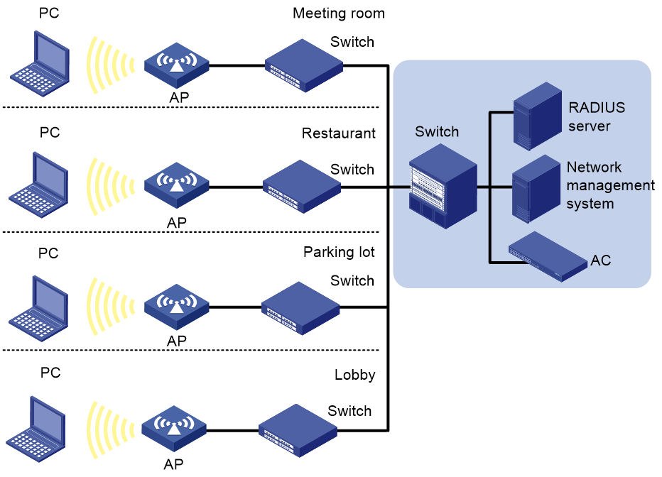
Figure4-2 Fat AP networking
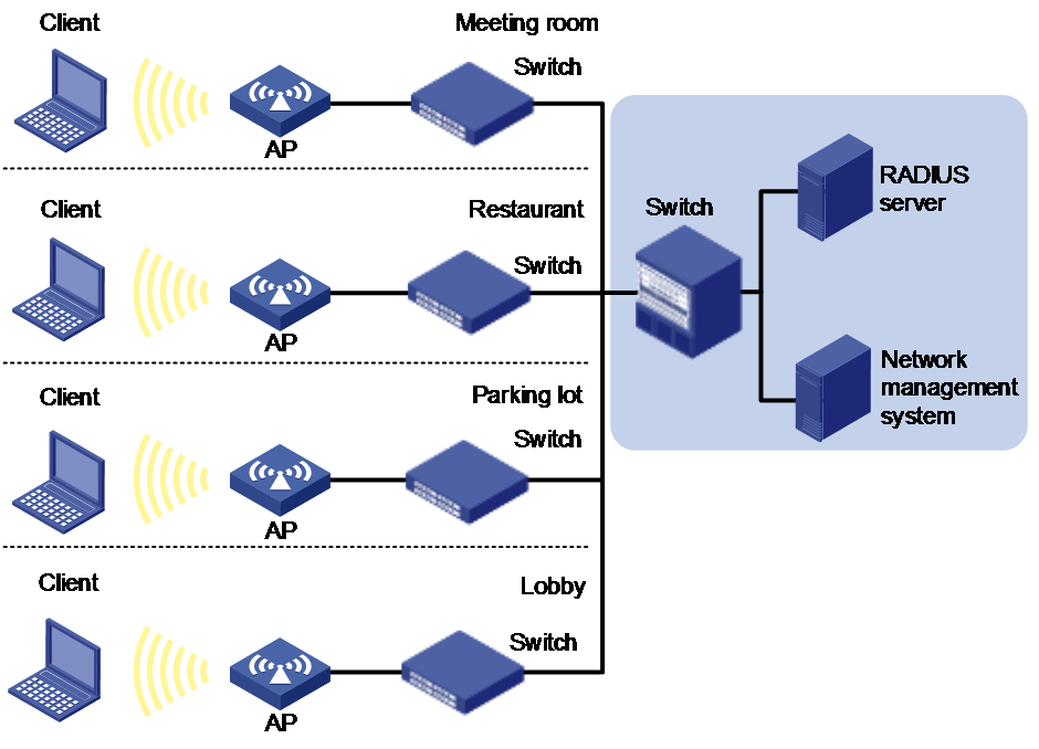
Table4-2 Technical specifications
|
Item |
Specification |
|
Dimensions (W × D × H) |
183 × 183 × 40 mm (7.20 × 7.20 × 1.57 in) |
|
Weight |
700 g (24.69 oz) |
|
Radios |
Three |
|
Antenna (built-in) |
· 2.4 G: 3 dBi gain · 5 G: 3 dBi gain |
|
Max. system power consumption |
25 W |
|
Power supply |
· 48 VDC · 802.3at-compliant PoE |
|
Protocol compliance |
· IEEE 802.11a/b/g/n/ac Wave 2 · 802.3at |
5 Appendix B Ports and LEDs
LEDs
Table5-1 LED description (fit AP mode)
|
LED |
Color |
Status |
Description |
|
|
N/A |
Off |
No power is present or the LED has been disabled. |
|
Amber |
Steady on |
· The AP has been initialized and the application program is starting up. · An initialization exception has occurred. |
|
|
Flashing at 1 Hz |
No radio cards have been detected. |
||
|
Flashing at 2 Hz |
The Ethernet interfaces are down and no mesh links are present. |
||
|
Green |
Steady on |
The AP has registered on an AC, but does not have any associated clients. |
|
|
Flashing at 0.5 Hz |
The AP is updating its application program. |
||
|
Flashing at 1 Hz |
Only the 2.4 G radio has associated clients. |
||
|
Flashing at 2 Hz |
The AP has started up, but has not registered on an AC. |
||
|
Blue |
Flashing at 1 Hz |
Only the 5 G radio has associated clients. |
|
|
Alternating between green and blue at 1 Hz |
Both the 2.4 G and 5 G radios have associated clients. |
||
Table5-2 LED description (fat AP mode)
|
LED |
Color |
Status |
Description |
|
|
N/A |
Off |
· The AP has been initialized and the application program is starting up. · An initialization exception has occurred. |
|
Amber |
Steady on |
The device is being initialized or an initialization error has occurred. |
|
|
Flashing at 1 Hz |
No radio cards have been detected. |
||
|
Flashing at 2 Hz |
The Ethernet interfaces are down and no mesh links are present. |
||
|
Green |
Steady on |
The AP has started up, but does not have any associated clients. |
|
|
Flashing at 1 Hz |
Only the 2.4 G radio has associated clients. |
||
|
Blue |
Flashing at 1 Hz |
Only the 5 G radio has associated clients. |
|
|
Alternating between green and blue at 1 Hz |
Both the 2.4 G and 5 G radios have associated clients. |
||
Ports
The AP provides the following ports:
· One USB port
· One console port
· Two 10/100/1000M Ethernet copper ports
· One power port
The AP also has a reset button and a security slot. The security slot is 8 × 4 mm (0.32 × 0.16 in) in size.
Figure5-1 Front view
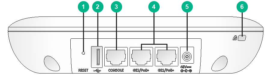
|
(1) Reset button |
(2) USB port |
(3) Console port |
|
(4) 10/100/1000M Ethernet fiber ports |
(5) Power port |
(6) Security slot |
Table5-3 Port descriptions
|
Port |
Standards and protocols |
Description |
|
Console port |
RS/EIA-232 |
Used by technical personnel only for device configuration and management. |
|
GE1/PoE+ |
· IEEE802.3 · IEEE802.3u · IEEE802.3af · IEEE802.3at |
Used for connecting the AP to an uplink device for Internet or MAN access. It can also receive PoE power from the uplink device. Ports GE1/PoE+ and GE2/PoE+ are named GE1/0/1 and GE1/0/2 in MAP files, and gigabitethernet1 and gigabitethernet2 on the AC, respectively. |
|
GE2/PoE+ |
||
|
48V DC |
N/A |
Used for receiving +48 VDC power from the local power source. |
|
USB |
USB 2.0 |
N/A |
|
Reset |
N/A |
Used for restarting the AP or deleting the configuration file. · To restart the AP, press the button for 5 seconds or shorter. · To restart the AP with its configuration file removed, press the button for over 5 seconds. |