- Table of Contents
- Related Documents
-
| Title | Size | Download |
|---|---|---|
| 01-Text | 2.27 MB |
Determining the installation position
Connecting the AP to a power source
Connecting a local power source
Connecting the AP to the network
Verifying network connectivity when the AP operates as a fit AP
Verifying network connectivity when the AP operates as a cloud-managed AP
3 Accessing the cloud-managed AP
Accessing the cloud-managed AP from the Web interface
Accessing the cloud-managed AP from the Oasis platform
4 Appendix A Technical specifications
1 Preparing for installation
Safety recommendations
|
|
WARNING! Only professional personnel can install and remove the AP and its accessories. You must read all safety instructions carefully before working with the AP. |
To avoid possible bodily injury and equipment damage, read the following safety recommendations before installing the AP. Note that the recommendations do not cover every possible hazardous condition.
· To avoid bodily injury and device damage, take adequate safety measures.
· Place the AP in a dry and flat location and take anti-slip measures.
· Keep the AP clean and dust-free.
· Do not place the AP in a moist area and avoid liquid intrusion.
· Keep the AP and installation tools away from walkways.
Site preparation
Before installing the AP, examine the installation site and make sure the AP will operate in a favorable environment. Make sure the temperate and humidity at the installation site meet the requirements in Table1-1.
Table1-1 Temperature and humidity requirements
|
Item |
Specification |
|
Operating temperature |
–10°C to +55°C (14°F to 131°F) |
|
Storage temperature |
–40°C to +70°C (–40°F to +158°F) |
|
Operating humidity |
5% RH to 95% RH, noncondensing |
Installation accessories
Figure1-1 Accessories provided with the AP
|
|
|
|
|
AP bracket |
Wall/Ceiling bracket |
Wall anchor kit |
|
|
|
|
|
M4×30 pan head screw |
M4×7 bolt |
|


Installation tools
When installing the AP, you might need the following tools. Prepare the installation tools yourself as required.
Figure1-2 Installation tools
|
|
|
|
|
|
Needle-nose pliers |
Wire-stripping pliers |
Diagonal pliers |
Marker |
|
|
|
|
|
|
Percussion drill (provided with multiple bits) |
Rubber hammer |
Phillips screwdriver |
|

2 Installing the AP
Installation flowchart
Figure2-1 Installation flowchart
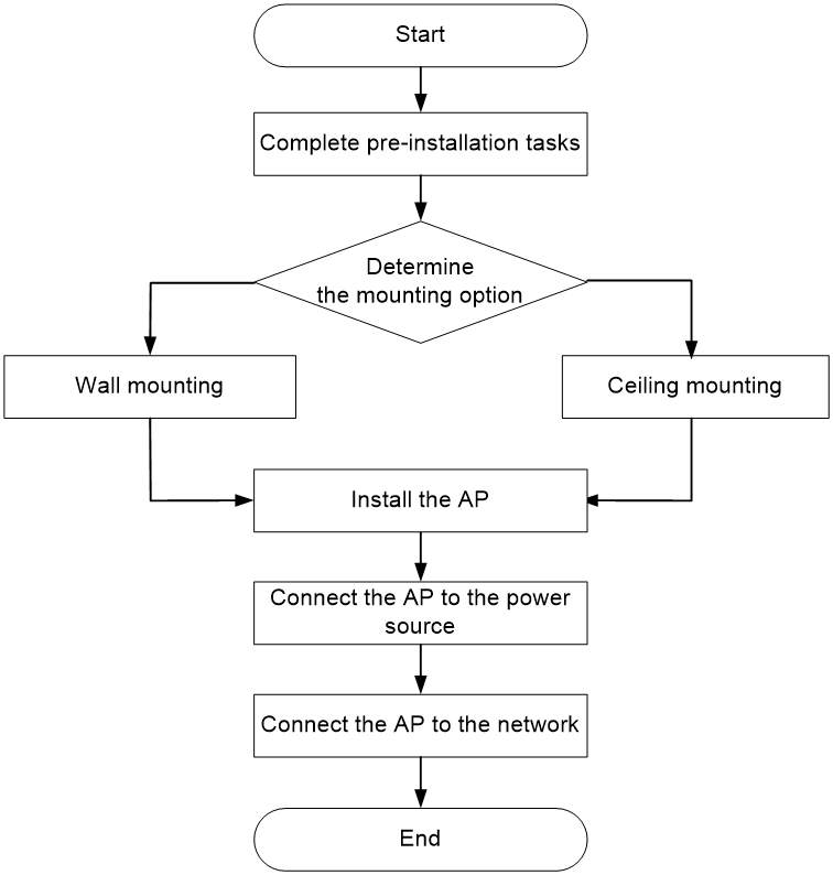
Pre-installation tasks
Before installing the AP, perform the following tasks:
· Connect the AP to a power source and the network. Examine the LEDs to verify that the AP is operating correctly. For information about AP LEDs, see "Appendix C LEDs."
· Record the MAC address and serial number at the rear of the AP for future use.
Determining the installation position
Determine the installation position for the AP by observing the following principles:
· As few obstacles (for example, walls) as possible exist between the AP and clients.
· The AP is far away from electronic devices (such as microwave oven) that might generate radio frequency (RF) noise.
· The AP does not hinder people’s daily work and life.
· The place is not water seeping, water soaking, or condensing.
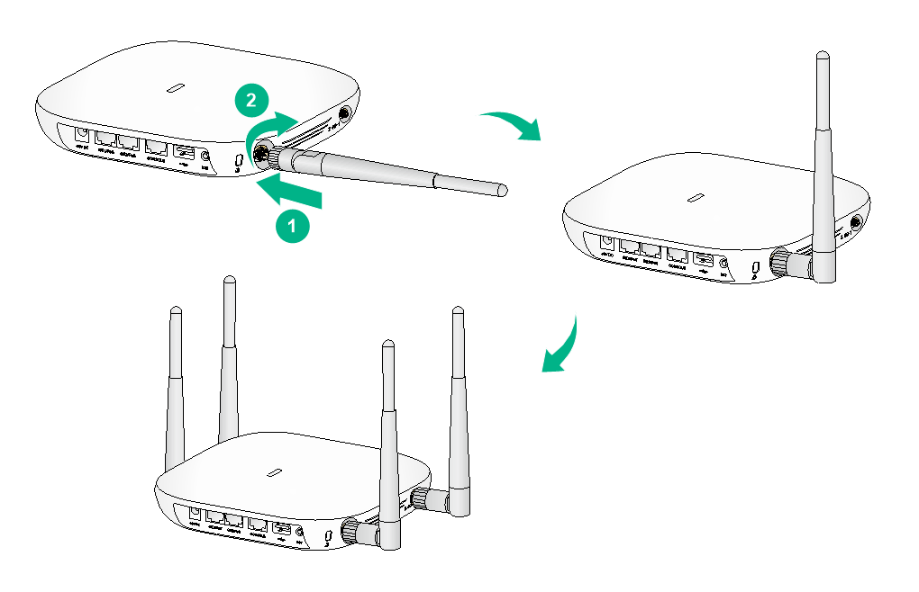
Attaching antennas to the AP
The WA5320E AP supports external antennas. To attach an antenna to the AP, screw the antenna onto an antenna connector on the AP until it is hand tight.
Figure2-2 Attaching antennas to the AP
Mounting the AP
The AP can be installed only indoors. You can mount the AP on a wall or a ceiling.
The WA5320 and WA5320E APs use the same installation procedure. The following procedures install a WA5320 AP.
The mounting bracket kit for the AP includes an AP bracket and a wall/ceiling bracket. To install the AP on a wall or ceiling, attach the AP bracket to the AP and the wall/ceiling bracket to the wall or ceiling.
Mounting bracket kit
The mounting bracket kit includes an AP bracket and a wall/ceiling bracket. To mount the AP on a wall or a ceiling, attach the AP bracket to the AP, and attach the wall/ceiling bracket to the wall or ceiling.
Figure2-3 AP bracket and wall/ceiling bracket
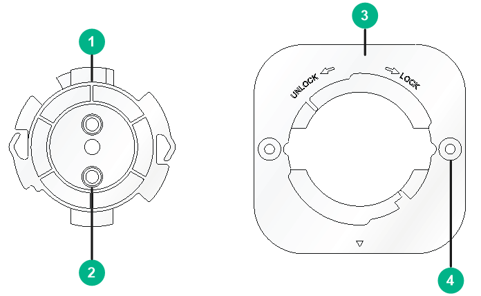
|
(1) AP bracket |
(2) Alignment pin |
|
(3) Wall/ceiling bracket |
(4) Installation hole |
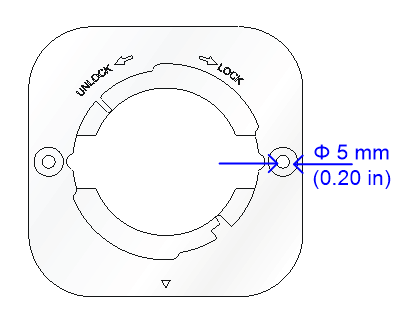
Figure2-4 Installation holes in the wall/ceiling bracket
Mounting the AP on a wall
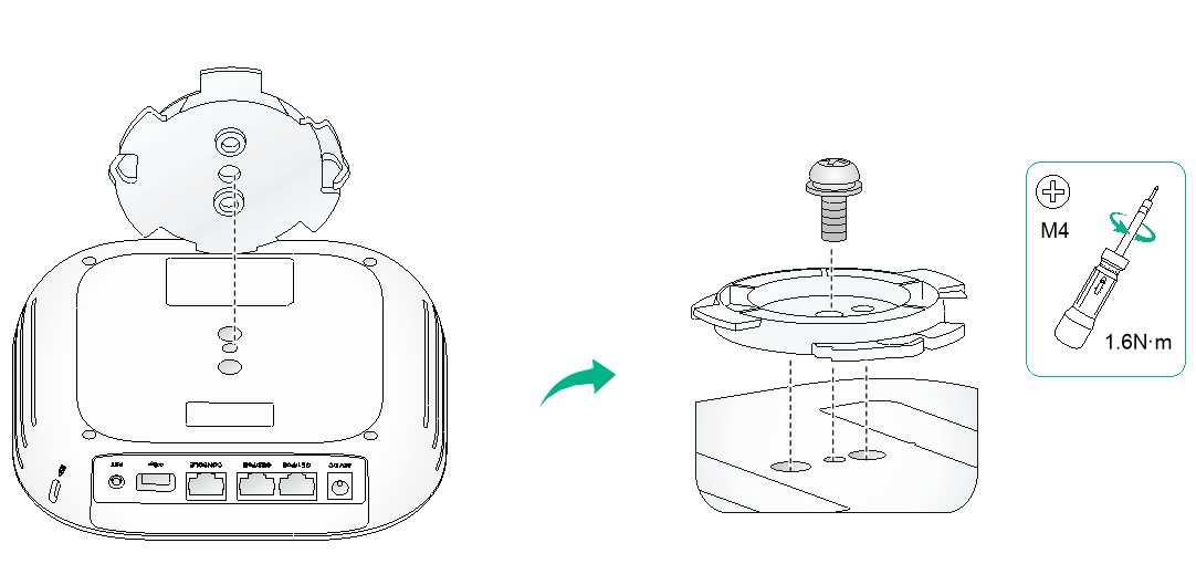
1. Align the guide pins on the AP bracket with the guide holes in the AP, and use the M4 × 7 screw to attach the AP bracket to the AP.
Figure2-5 Attaching the AP bracket to the AP
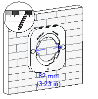
2. Mark the installation holes on the wall by using the wall/ceiling bracket.
Figure2-6 Marking the installation holes on the wall
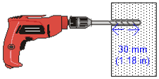
3. Drill two holes with a diameter of 6 mm (0.24 in) and a depth of 30 mm (1.18 in) in the marked locations.
Figure2-7 Drilling holes in the wall
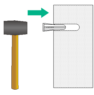
4. Insert a screw anchor into each hole, and tap the screw anchor by using a rubber hammer until it is all flush with the wall surface.
Figure2-8 Hammering wall anchors into holes
5. Align the installation holes in the wall/ceiling bracket with the screw anchor holes in the wall, and use screws to attach the wall bracket to the wall.
Figure2-9 Attaching the wall bracket to the wall
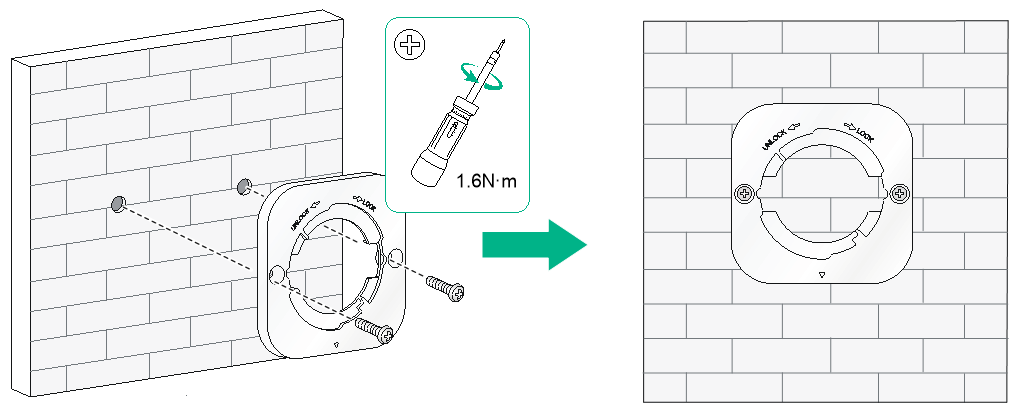
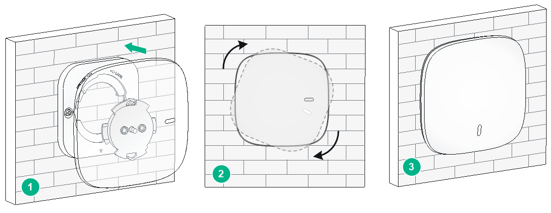
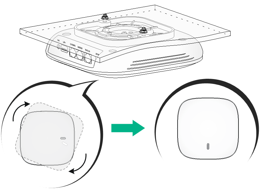
6. Align the AP with the wall/ceiling bracket in the direction as shown Figure2-10, and rotate the AP clockwise until it clicks into place.
Figure2-10 Attaching the AP to the wall/ceiling bracket
Mounting the AP on a ceiling
|
|
WARNING! The ceiling for installing the AP must be less than 18 mm (0.71 in) in thickness, and can bear a load of 5 kg (11.02 lb). If the ceiling is not strong enough, use boards to reinforce the ceiling as a best practice. |
To mount the AP on a ceiling:
1. Align the guide pins on the AP bracket with the guide holes in the AP, and use a M4 × 7 screw to attach the AP bracket to the AP, as shown in Figure2-5.
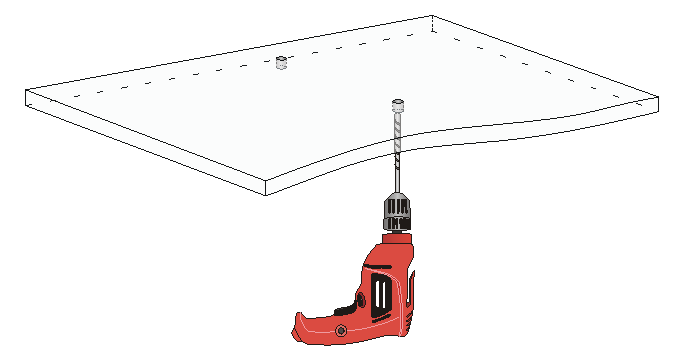
2. Remove the ceiling tile and use the ceiling bracket to mark the installation holes on the ceiling tile. Drill two holes with a diameter of 5 mm (0.20 in) in the marked positions.
Figure2-11 Drilling holes in the ceiling tile
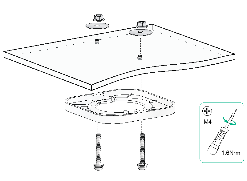
3. Thread pan-head screws through the installation holes in the wall/ceiling bracket and into the holes in the ceiling. Fasten washers and nuts at the other side of the ceiling to attach the mounting bracket to the ceiling.
Figure2-12 Attaching the wall/ceiling bracket to the ceiling
4. Align the AP with the wall/ceiling bracket in the direction as shown in Figure2-13, and rotate the AP clockwise until it clicks into place.
|
|
WARNING! Verify that the AP is securely seated over the wall/ceiling bracket. |
Figure2-13 Attaching the AP to the wall/ceiling bracket
Connecting the AP to a power source
You can supply power to the AP by using a local power source or through 802.3af/802.at PoE as required. Before powering the AP, make sure the power source (the local power source or the PSE) is reliably grounded.
Connecting a PoE power source
|
|
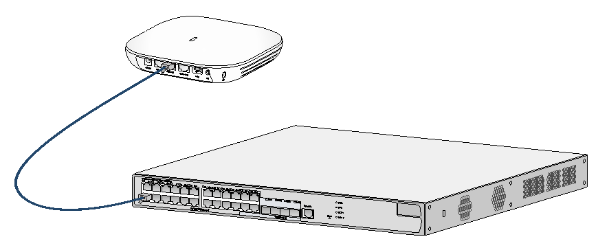
CAUTION: If you are to power the AP through PoE, connect one of the GE ports to a PoE switch. If you are to connect the other GE port, wait until the AP powers up. |
To power the AP through PoE, use an Ethernet cable to connect an Ethernet port on the AP to a PoE switch.
Figure2-14 Powering the AP through PoE
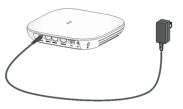
Connecting a local power source
You can use an AC/DC power adapter to connect the AP to a local power source. No power adapter is provided with the AP. Prepare one yourself as required. Table2-1 describes the power adapter specifications.
Table2-1 Power adapter specifications
|
Item |
Specification |
|
Input |
100 VAC to 240 VAC |
|
Output |
+48 VDC |
Figure2-15 Using a power adapter to connect the AP to a local power source
Check after power-on
Examine the LEDs on the AP after you power on it to verify that the AP is operating correctly. For more information about AP LEDs, see "Appendix C LEDs."
Connecting the AP to the network
Connect the Ethernet ports on the AP to an Ethernet switch and verify network connectivity.
Verifying network connectivity when the AP operates as a fit AP
All AP settings are configured on the AC when the AP operates as a fit AP. Execute the display wlan ap all command on the AC. If the AP status is R/M, the AP has been connected to the network.
<AC> display wlan ap all
Total number of APs: 1
Total number of connected APs: 1
Total number of connected manual APs: 1
Total number of connected auto APs: 0
Total number of connected common APs: 1
Total number of connected WTUs: 0
Total number of inside APs: 0
Maximum supported APs: 3072
Remaining APs: 3071
Total AP licenses: 128
Remaining AP licenses: 127
Sync AP licenses: 0
AP information
State : I = Idle, J = Join, JA = JoinAck, IL = ImageLoad
C = Config, DC = DataCheck, R = Run M = Master, B = Backup
AP name AP ID State Model Serial ID
ap1 1 R/M WA5320 219801A0YD8166E00000
Verifying network connectivity when the AP operates as a cloud-managed AP
The WA5320 AP can operate as a cloud-managed AP. When the AP operates in cloud-managed AP mode, use a wireless client that connects to the AP to access the network. If the AP can access the network, the AP has been connected to the network.
3 Accessing the cloud-managed AP
You can access the cloud-managed AP from the local Web interface or the Oasis platform.
Accessing the cloud-managed AP from the Web interface
You can access the cloud-managed AP from the Web interface only through a wireless connection.
Make sure the wireless client you use for cloud-managed AP login has a dynamically obtained IP address.
To access the cloud-managed AP from the Web interface:
1. Connect a wireless client to SSID H3C_xxxxxx. The xxxxxx argument represents the last six characters of the AP's MAC address.
2. Enter http://myap.h3c.com in the address bar of a browser and then press Enter.
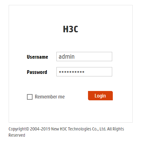
3. On the login page that opens, enter the username and password, and then lick Login.
The default username and password are admin and h3capadmin, respectively.
Figure3-1 Login page
Accessing the cloud-managed AP from the Oasis platform
By default, the AP obtains IP addresses from the DHCP server. To access the AP from the Oasis platform, make sure the AP can reach the public network.
To access the AP from the Oasis platform:
1. Access the Oasis platform.
¡ To access the platform from the Web interface, visit oasis.h3c.com through a browser, and then enter the username and password on the page that opens.
¡ To access the platform from an app, use a smartphone to scan the following QR code and install Oasis Manager. Then, open the app and enter the username and password on the page that opens.
Make sure the smartphone uses Android 4.0, iOS7.0, or a higher version.
Figure3-2 Oasis Manager QR code

2. Add the AP to the Oasis platform. For more information, see the H3C Oasis Platform Deployment Guide.
4 Appendix A Technical specifications
The H3C WA5320E can operate as a fit AP. The WA5320 can operate as a fit AP, or operate in cloud-managed AP mode to work with the Oasis platform.
Figure4-1 Fit AP networking
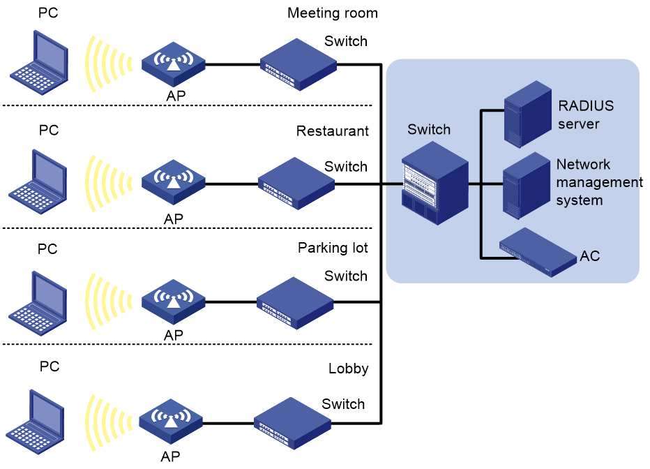
Figure4-2 Cloud-managed AP networking

Table4-2 Technical specifications
|
Item |
WA5320 |
WA5320E |
|
Dimensions (W × D × H) |
170 × 170 ×35.5 mm (6.69 × 6.69 ×1.40 in) |
170 × 170 ×35.5 mm (6.69 × 6.69 ×1.40 in) |
|
Weight |
340 g (11.99 oz) |
360 g (12.70 oz) |
|
Antenna |
· 2.4 GHz built-in antenna: 3 dBi gain · 5 GHz built-in antenna: 3 dBi gain |
External antennas, user supplied For the antenna gain, see the user guide for the antenna. |
|
≤ 12.95 W |
≤ 12.95 W |
|
|
IEEE standards |
IEEE802.11a/b/g/n/ac wave2 |
IEEE802.11a/b/g/n/ac wave2 |
|
Radios |
2 |
2 |
5 Appendix B Ports
WA5320
The WA5320 AP provides the following ports:
· One console port
· Two GE ports
· One USB port
· One power port
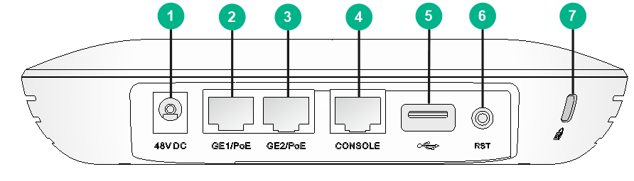
Figure5-1 Ports on the AP
|
(1) Power port |
(2) 10/100/1000 Mbps Ethernet port (GE1/PoE) |
|
(3) 10/100/1000 Mbps Ethernet port (GE2/PoE) |
(4) Console port |
|
(5) USB port |
(6) Reset button |
|
(7) Security slot |
|
|
|
NOTE: · The security slot is 7 × 3 mm (0.28 × 0.12 in) in size. · If you press and hold the reset button for 5 seconds or less, the AP restarts. If you press and hold the reset button for over 5 seconds, the AP restarts with factory defaults. |
Table5-1 Port descriptions
|
Port |
Standards and protocols |
Description |
|
Console port |
RS/EIA-232 |
Used by technical personnel for configuration and management. |
|
10/100/1000 Mbps Ethernet ports (GE1/PoE and GE2/PoE) |
· IEEE802.3 · IEEE802.3u · IEEE802.3af |
Used for connecting the AP to an uplink device for Internet or MAN access. It can also receive PoE power from the uplink device. In fit AP mode, ports GE1/PoE and GE2/PoE are named GE1/0/1 and GE1/0/2 in MAP files and gigabitethernet 1 and gigabitethernet 2 on the AC, respectively. |
|
USB port |
USB 2.0 |
Used for transferring data or supplying power. |
|
Power port (48V DC) |
N/A |
Used for receiving +48 VDC power from the local power source. |
WA5320E
The WA5320E AP provides the following ports:
· One console port
· Two GE ports
· One USB port
· Four SMA connectors
· One power port
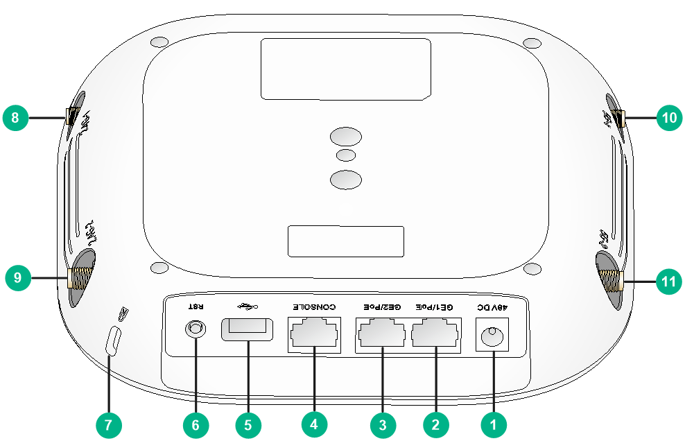
Figure5-2 Ports on the AP
|
(1) Power port |
(2) 10/100/1000 Mbps Ethernet port (GE1/PoE) |
|
(3) 10/100/1000 Mbps Ethernet port (GE2/PoE) |
(4) Console port |
|
(5) USB port |
(6) Reset button |
|
(7) Security slot |
(8) SMA connector (2.4G-1) |
|
(9) SMA connector (2.4G-2) |
(10) SMA connector (5G-1) |
|
(11) SMA connector (5G-2) |
|
|
|
NOTE: · The security slot is 7 × 3 mm (0.28 × 0.12 in) in size. · If you press and hold the reset button for 5 seconds or less, the AP restarts. If you press and hold the reset button for over 5 seconds, the AP restarts with factory defaults. |
Table5-2 Port and button descriptions
|
Port |
Standards and protocols |
Description |
|
Console port |
RS/EIA-232 |
Used by technical personnel for device configuration and management. |
|
10/100/1000 Mbps Ethernet ports (GE1/PoE and GE2/PoE) |
· IEEE802.3 · IEEE802.3u · IEEE802.3af |
Used for connecting the AP to an uplink device for Internet or MAN access. It can also receive PoE power from the uplink device. In fit AP mode, ports GE1/PoE and GE2/PoE are named GE1/0/1 and GE1/0/2 in MAP files and gigabitethernet 1 and gigabitethernet 2 on the AC, respectively. |
|
USB port |
USB 2.0 |
Used for transferring data or supplying power. |
|
2.4G/5G antenna connector (2.4G-1, 2.4G-2, 5G-1, 5G-2) |
· IEEE802.11a · IEEE802.11b · IEEE802.11g · IEEE802.11n · IEEE802.11ac wave2 |
Used for connecting antennas. |
|
Power port (48V DC) |
N/A |
Used for receiving +48 VDC power from the local power source. |
6 Appendix C LEDs
Table6-1 LED descriptions (fit mode)
|
LED |
Status |
Description |
|
|
|
Off |
No power is present or the LED has been disabled. |
|
|
Yellow |
Steady on |
The AP is initializing, or an initialization exception has occurred. |
|
|
Flashing at 1 Hz |
No radio interfaces have been detected. |
||
|
Flashing at 2 Hz |
The Ethernet interfaces are down and no mesh links are established. |
||
|
Green |
Steady on |
The AP has registered to an AC, but does not have any associated clients. |
|
|
Flashing at 0.5 Hz |
The AP has started up but has not registered to any AC. |
||
|
Flashing at 1 Hz |
Only the 2.4G radio has associated clients. |
||
|
Flashing at 2 Hz |
The AP is upgrading the image. |
||
|
Blue |
Flashing at 1 Hz |
Only the 5G radio has associated clients. |
|
|
Alternating between green and blue at 1 Hz |
Both the 2.4G and 5G radios have associated clients. |
||
Table6-2 LED descriptions (cloud mode, supported only by the WA5320 AP)
|
LED |
Status |
Description |
|
|
|
Off |
No power is present or the LED has been disabled. |
|
|
Yellow |
Steady on |
The AP is initializing, or an initialization exception has occurred. |
|
|
Flashing at 1 Hz |
No radio interfaces have been detected. |
||
|
Flashing at 2 Hz |
The Ethernet interfaces are down and no mesh links are established. |
||
|
Green |
Steady on |
The AP is in standby state and does not have any associated clients. |
|
|
Flashing at 1 Hz |
Only the 2.4G radio has associated clients. |
||
|
Flashing at 2 Hz |
The AP is upgrading the image. |
||
|
Blue |
Flashing at 1 Hz |
Only the 5G radio has associated clients. |
|
|
Alternating between green and blue at 1 Hz |
Both the 2.4G and 5G radios have associated clients. |
||