- Table of Contents
- Related Documents
-
| Title | Size | Download |
|---|---|---|
| 01-Text | 1.22 MB |
Overview
Table 1 PSR3000-54A power module features
|
Feature |
Description |
|
Protection |
Protection against input under-voltage, input over-voltage, output over-voltage, output short circuit, output under-current, output over-current, and overheat. |
|
Redundancy |
The power modules can operate in N+1 or N+N redundancy. For more information, see "Power module configuration." |
|
Hot swapping |
You can install or remove a power module when the device is operating. |
The power module shuts down automatically when its temperature exceeds the acceptable range. When the temperature returns to the acceptable range, the power module automatically restarts.
Front panel
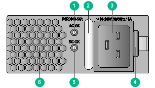
Figure 1 Front panel
|
(1) Power input LED (AC OK) |
(2) Handle |
|
(3) AC input receptacle |
(4) Latch |
|
(5) Power output LED (DC OK) |
(6) Air outlet vents |
LEDs
Each PSR3000-54A power module has two LEDs.
Table 2 LED description
|
LED |
Mark |
Color |
Description |
|
Power input LED |
AC OK |
Off |
No AC power input. |
|
Low AC input voltage. The power module has entered protected state. |
|||
|
Green |
Normal AC input. |
||
|
Power output LED |
DC OK |
Green |
Normal DC output. |
|
Red |
DC output failure. An alarm condition occurs, for example, output short circuit, output over-current, output over-voltage, output under-voltage, or remote shutdown. The power module has entered the protected state. |
||
|
Orange |
High temperature. |
|
|
NOTE: After the circuit breaker of the power module is switched off, the LEDs on the power module will remain on for a while. |
Technical specifications
Table 3 Technical specifications
|
Item |
Specifications |
|
|
Rated input voltage |
100 to 240 VAC @ 50 or 60 Hz |
|
|
Rated output voltage |
54 VDC |
|
|
Maximum input current |
16 A |
|
|
Maximum output current |
55.6 A |
|
|
Maximum output power |
· 1200 W @ 100 to 175 VAC · 3000 W @ 175 to 240 VAC |
|
|
Dimensions (H × W × D) |
41 × 100 × 332 mm (1.61 × 3.94 × 13.07 in) |
|
|
Ambient temperature |
Operating temperature |
–10°C to +50°C (–14°F to +122°F) |
|
Storage temperature |
–40°C to + 70°C (–40°F to +158°F) |
|
Power module configuration
Follow these guidelines to configure power modules for the device:
· Determine the total number of power modules based on the actual power consumption, the power module slot number, and power redundancy design.
· Determine the power module redundancy design based on the power source conditions.
¡ When two mains power inputs are provided, you can configure the power modules in N+N redundancy. N+N must be not greater than the total number of power module slots.
¡ When one mains power input is provided, you can configure the power modules in N+1 or N+N redundancy. N+1 or N+N must be not greater than the total number of power module slots.
· For easy usage and maintenance, configure a circuit breaker for each power input. The rated current of the circuit breaker must be a minimum of 20 A.
Installing and removing the power module
Installing the power module
To avoid bodily injury and device damage, follow the procedures in Figure 2 to install a power module.
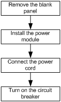
Figure 2 Power module installation procedure
Before the installation, prepare an ESD wrist strap and a flat-blade screwdriver yourself.
Installing the power module
1. Wear an ESD wrist strap, and make sure the strap makes good skin contact and is correctly grounded.
2. Remove the blank panel from the target power module slot.
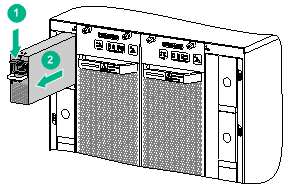
¡ If the blank panel is as shown in Figure 3, thread the flat-blade screwdriver through the hole in the handle of the blank panel and pull the blank panel out.
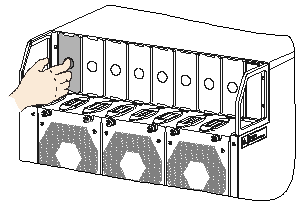
¡ If the blank panel is as shown in Figure 4, put your forefinger in the hole in the blank panel and pull the blank panel out.
Skip this step if the target slot has no blank panel installed.
Figure 3 Removing a blank panel (1)
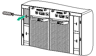
Figure 4 Removing a blank panel (2)
3. Unpack the power module.
4. Correctly orient the power module.
If you install the power module in a left power module slot, make sure the latch is above the handle. If you install the power module in a right power module slot, make sure the latch is below the handle.
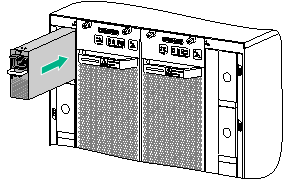
5. Holding the handle of the power module with one hand and supporting the bottom of the power module with the other, slide the power module along the guide rails into the slot until you hear a click.
The power module is foolproof. If the power module is oriented incorrectly, you cannot install the power module into the slot. If you encounter a hard resistance while inserting the power module, pull out the power module, reorient it, and then insert it again.
Figure 5 Installing a power module
Connecting the power cord
|
|
WARNING! · Make sure each power cord has a separate circuit breaker. · Turn off the circuit breaker before you connect the power cord. |
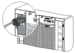
The PSR3000-54A power module is provided with a 16 A AC power cord with a C19 angled connector. You can also use a 16 A AC power cord with a straight entry C19 connector.
To connect the power cord:
1. Plug the AC power cord connector into the AC input receptacle of the power module.
2. Use a removable cable tie or self-adhesive cable tie to secure the power cord to the handle of the power module.
Route the power cords of the left power modules to the left side. Route the power cords of the right power modules to the right side.
Figure 6 Securing the power cord with a C19 angled connector by using a removable cable tie
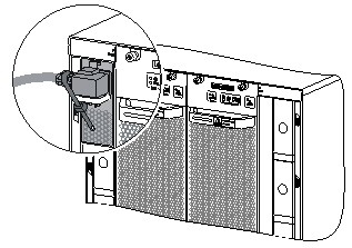
Figure 7 Securing the power cord with a straight entry C19 connector by using an self-adhesive cable tie
3. Plug the other end of the power cord into an AC power receptacle, and turn on the circuit breaker.
4. Verify that the power input LED is ON. If the LED is on, the power cord is correctly connected. If the LED is OFF, troubleshoot the installation process.
Removing a power module
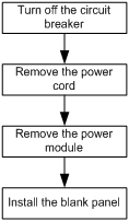
To avoid device damage and bodily injury, follow the procedures in Figure 8 to remove the power module.
Figure 8 Power module removal procedure
Before you remove a power module, prepare an ESD wrist strap yourself.
Removing the power cord
1. Turn off the circuit breaker of the power cord.
2. Wear an ESD wrist strap, and make sure the strap makes good skin contact and is correctly grounded.
3. Remove the cable tie, and pull the power cord out.
Removing the power module
|
|
CAUTION: Before you insert a removed power module into a power module slot, make sure the LEDs on the power module are off. |
To remove the power module:
1. Pressing the latch towards the handle direction, pull the power module out along the guide rails until it is part way out of the slot.
2. As shown in Figure 9, grasping the handle of the power module with one hand and supporting the bottom of the power module with the other hand, pull the module slowly along the guide rails out of the slot.
Figure 9 Removing a power module
3. Place the power module on an antistatic mat.
