- Table of Contents
- Related Documents
-
| Title | Size | Download |
|---|---|---|
| 01-Text | 946.11 KB |
Service data interaction modes of the VM
Deploying the EPS gateway in a network
Prerequisites for EPS gateway deployment
Preparing a management host and tool software
Connecting the management host and EPS gateway
Configuring IP address settings for the management host
Preparing for VNC Viewer login
Configuring VLAN settings for the VM NIC
Configuring VM network settings
Specifying an EPS server for the EPS scanner
Verifying the functionalities of the EPS gateway
Exporting the VM to a .pkg file
Display and maintenance commands for VM management
Introduction
The H3C MSR3610-I ES Gateway (referred to as the EPS gateway hereinafter) is deployed in the Endpoint Profiling System (EPS). The EPS gateway has capabilities of keenly perceiving network connection, proactively identifying access devices, and managing device baselines. In addition, the EPS gateway can uniformly scan and monitor various endpoints.
The EPS gateway is shipped with a VM that is installed with an EPS 2.0 scanner. The VM runs the CentOS operating system and has a high-performance SR-IOV NIC. To deploy the EPS gateway in a network, you need to configure IP address settings for the VM.
Factory defaults
Interfaces
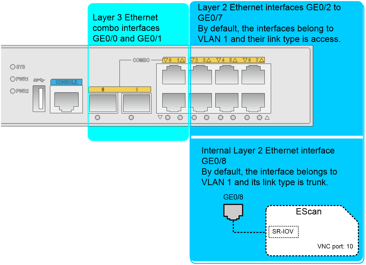
The EPS gateway provides the following interfaces by default:
· Layer 3 Ethernet combo interfaces GigabitEthernet 0/0 and GigabitEthernet 0/1, in which the IP address of GigabitEthernet 0/0 is 192.168.0.1/23.
· Layer 2 Ethernet interfaces GigabitEthernet 0/2 to GigabitEthernet 0/8, in which GigabitEthernet 0/8 is an internal interface used to connect the SR-IOV NIC of the VM.
Figure 1 shows the interfaces on the EPS gateway.
Figure 1 Interface network diagram
Default VM parameters
The EPS gateway is shipped with a VM. The default VM parameters are as follows:
· The VM name is EScan, which is case sensitive.
· The VM operating system is CentOS.
· The VNC port number is 10. Users can log in to the desktop of the VM by using this port number through VNC Viewer.
· The VM is assigned an SR-IOV NIC. The SR-IOV NIC does not have an IP address.
VM login method
To use a management host to log in to the VM, make sure the management host can reach the EPS gateway.
The EPS gateway allows users that use VNC Viewer to log in to the desktop of the VM by connecting to the VM VNC server in VNC server IP address:VNC port number format.
· VNC server IP address—The IP address of a Layer 3 interface or VLAN interface on the EPS gateway.
· VNC port number—The VNC port number of the VM. The VNC port number is configurable at the CLI.
Figure 2 VM login through the IP address of a VLAN interface
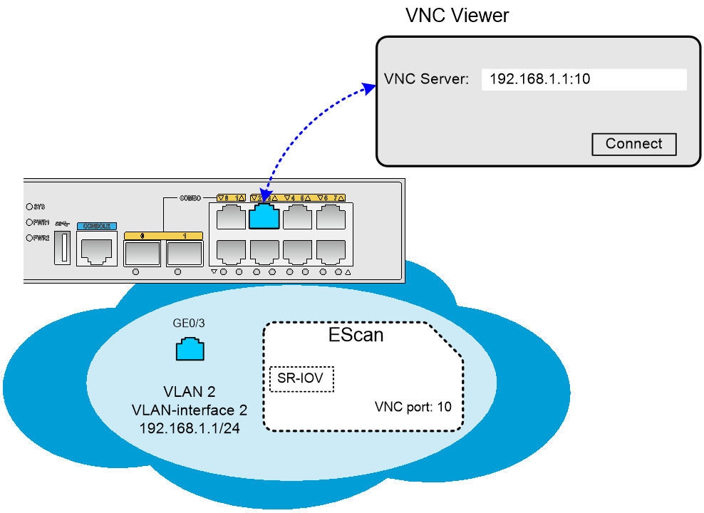
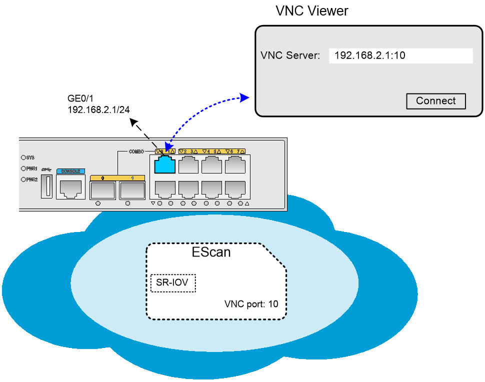
Figure 3 VM login through the IP address of a Layer 3 Ethernet interface
VM network configuration
The VM deployed on the EPS gateway is assigned a high-performance SR-IOV NIC by default. The NIC does not have an IP address. For client hosts to access the VM, log in to the desktop of the VM and configure an IP address for the VM NIC according to the user network configuration.
Service data interaction modes of the VM
The EPS gateway provides the following service data interaction modes for the VM:
· Intra-VLAN broadcasting.
· Layer 3 routing.
|
|
IMPORTANT: By default, the SR-IOV NIC of the VM does not belong to a VLAN. · If the intra-VLAN broadcasting mode is used, configure the VM and the client hosts that interact with the VM to belong to the same VLAN. · If the Layer 3 routing mode is used, assign the VM NIC to a VLAN (not VLAN 1) and configure the IP address of the VLAN interface as the default gateway address of the VM. |
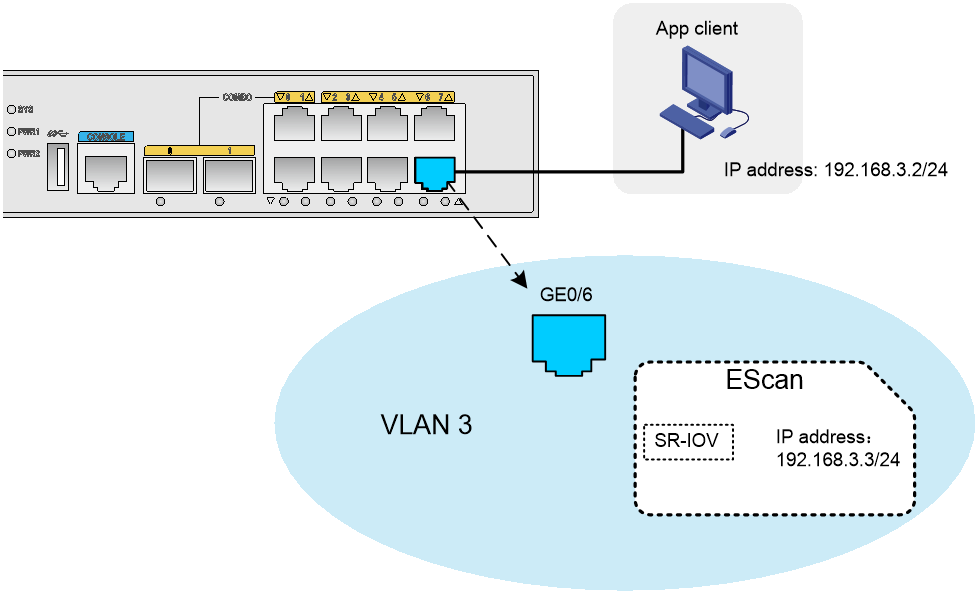
Intra-VLAN broadcasting
For a client host to access the VM, configure the client host and the VM to use IP addresses that belong to the same subnet. As shown in Figure 4, the client host accesses the VM through a Layer 2 Ethernet interface on the EPS gateway.
Figure 4 Intra-VLAN broadcasting mode
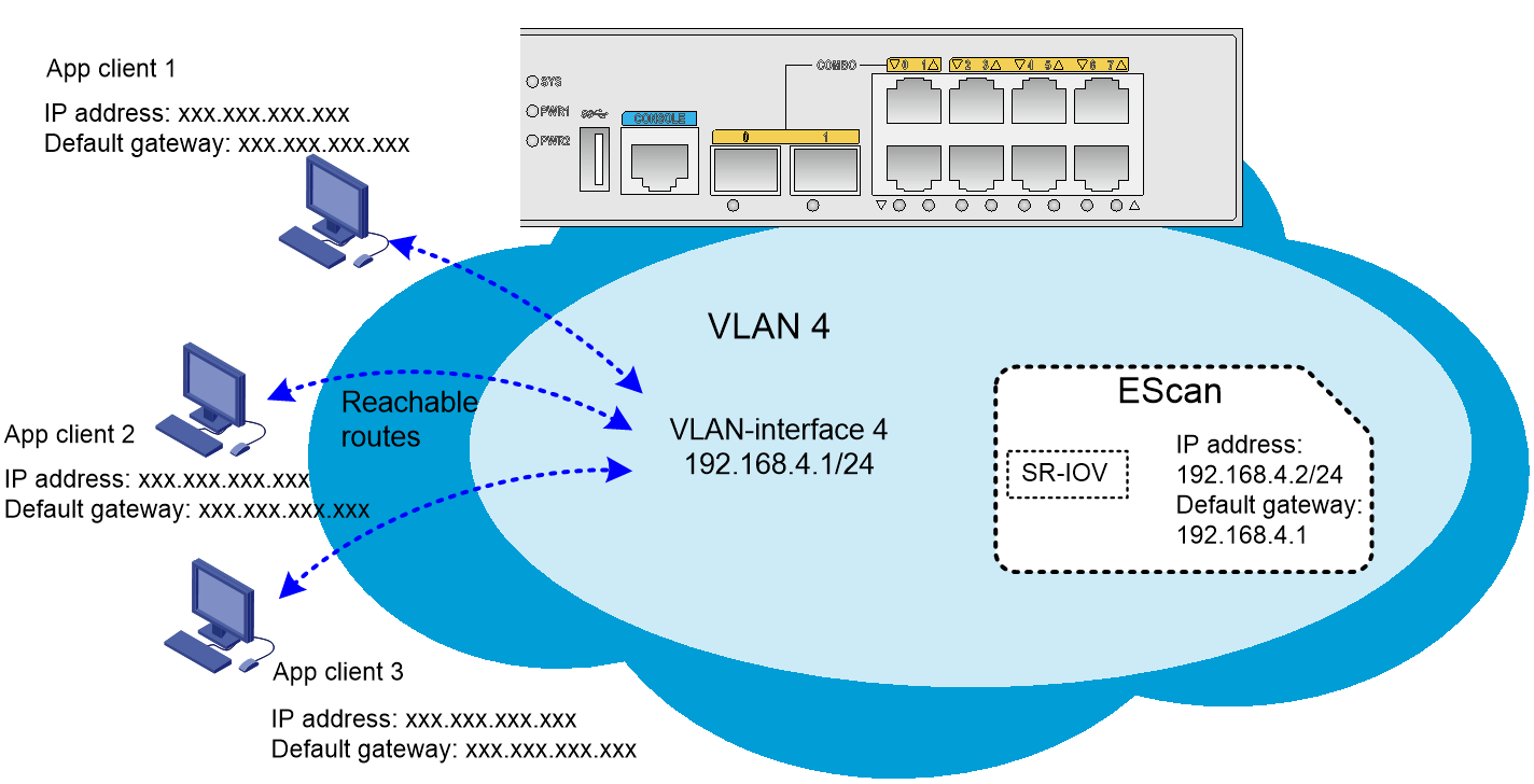
Layer 3 routing
Set the IP address and default gateway address of the VM to IP addresses that are reachable to client hosts. The client hosts access the VM through a Layer 3 Ethernet interface or VLAN interface on the EPS gateway, as shown in Figure 5.
Deploying the EPS gateway in a network
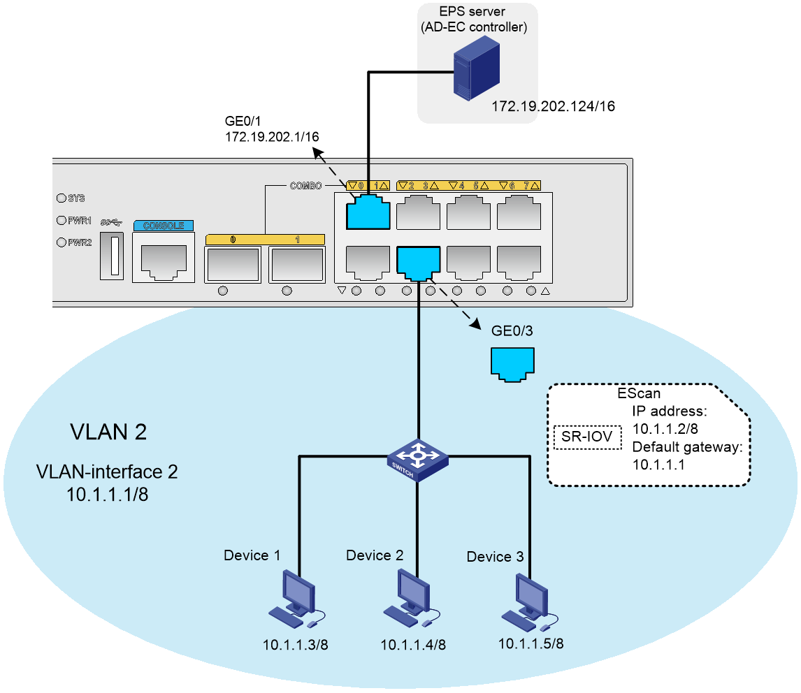
Network configuration
As shown in Figure 6, Device 1, Device 2, and Device 3 access Layer 2 Ethernet interface GigabitEthernet 0/3 on the EPS gateway through the switch.
The EPS server is connected to Layer 3 Ethernet interface GigabitEthernet 0/1 on the EPS gateway.
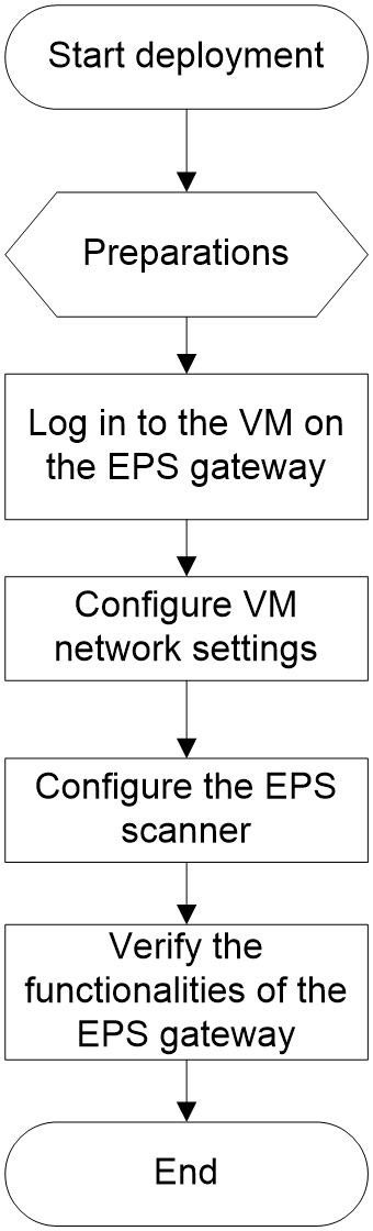
Deployment process
Deploy the EPS gateway to scan endpoints in the network, collect data for the endpoints, and upload the scanned data to the EPS server. Figure 7 shows the deployment process of the EPS gateway.
Prerequisites for EPS gateway deployment
Preparing a management host and tool software
· Prepare a management host used to log in to the VM on the EPS gateway. Prepare a serial cable and a network cable to connect the host to the EPS gateway.
· Install a terminal emulation program (for example, PuTTY) on the management host used to log in to the CLI of the EPS gateway for VM parameter configuration and query.
· Install remote login software (for example, VNC Viewer) on the management host used to log in to the desktop of the VM and process services on the VM operating system.
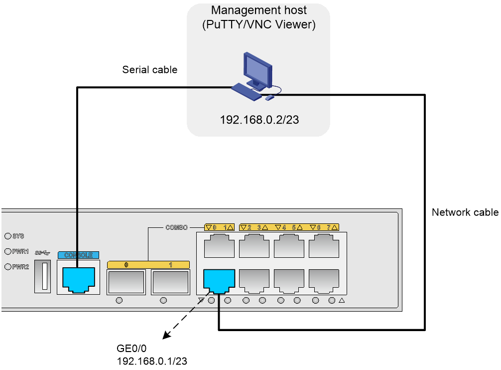
Connecting the management host and EPS gateway
Use the serial cable to connect the management host and the console port of the EPS gateway. The management host can use the PuTTY software to log in to the CLI of the EPS gateway through the serial cable.
Use the network cable to connect the management host and GigabitEthernet 0/0 on the EPS gateway. The management host can communicate with the EPS gateway through the network cable.
Figure 8 shows the network diagram.
Figure 8 Connecting the management host and EPS gateway
Configuring IP address settings for the management host
Procedure
1. Open the Network and Sharing Center and select Local Area Connection.
2. In the dialog box that opens, click Properties.
3. In the dialog box that opens, select Internet Protocol Version 4 (TCP/IPv4) and click Properties.
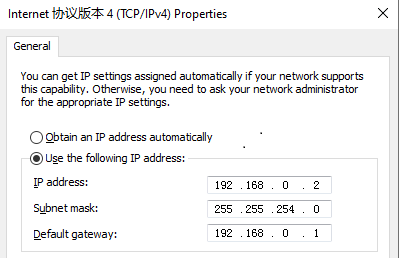
4. In the dialog box that opens, configure the IP address settings as shown in Figure 9.
In this example, the IP address is 192.168.0.2/23.
Figure 9 Configuring IP address settings for the management host
Verifying the configuration
# Verify that the management host can ping the EPS gateway and the EPS gateway can ping the management host. (Details not shown.)
Preparing for VNC Viewer login
About this task
To use VNC Viewer to log in to the desktop of the VM, you must obtain the VM name and VNC port number and make sure the VM has been started. Perform this task to obtain the VM name and VNC port number and view the VM status. If the VM has not been started, start the VM.
By default, the VM name on the EPS gateway is EScan and the VNC port number is 10.
Obtaining the VM name and VM status
Log in to the CLI of the EPS gateway and use the display vmlist command to obtain the VM name and status. If the VM is in shutoff state, use the start vm command to start the VM.
# Obtain the VM name and status.
<H3C> display vmlist
Id Name Status
------------------------------------------
1 EScan shutoff
# Start the VM.
<H3C> system-view
[H3C] vmm
[H3C-vmm] start vm EScan
Domain EScan started
Obtaining the VNC port number of the VM
# Obtain the VNC port number of the VM.
<H3C> display vncport vm EScan
:10
Configuring VLAN settings for the VM NIC
About this task
By default, the NIC of the VM on the EPS gateway is not assigned to any VLAN. For the VM to communicate with the EPS server and service endpoints, you must manually assign the VM NIC to a VLAN. In addition, specify the IP address of the VLAN interface as the default gateway address of the VM for Layer 3 communication.
Procedure
1. Display PF and VF interface information about the SR-IOV NIC on VM EScan.
<H3C> system-view
[H3C] vmm
[H3C-vmm] display vminterface vm EScan
Interface Type Model MAC
-----------------------------------------------------------------
PF0/VF0 hostdev - 04D7-A557-9603
2. Create VLAN 2 and assign the SR-IOV NIC of the VM to the VLAN:
# Create VLAN 2.
<H3C> system-view
[H3C] vlan 2
[H3C-vlan2] quit
# Assign the SR-IOV NIC of VM EScan to VLAN 2.
[H3C] vmm
[H3C-vmm] set sriov pf 0 vf 0 vlan 2
3. Configure an IP address for VLAN-interface 2. This IP address will be used as the default gateway address for the VM to communicate with the EPS server and service endpoints.
<H3C> system-view
[H3C] interface vlan-interface 2
[H3C-Vlan-interface20] ip address 10.1.1.1 8
[H3C-Vlan-interface20] quit
Logging in to the VM
In this example, the VNC server IP address is the default IP address of Layer 3 Ethernet interface GigabitEthernet 0/0 on the EPS gateway.
Logging in to the desktop of the VM
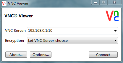
1. On the management host, open VNC Viewer, and connect to the desktop of the VM by using the VNC server in the format of VNC server IP address:VNC port number, as shown in Figure 10.
Figure 10 VNC Viewer login interface
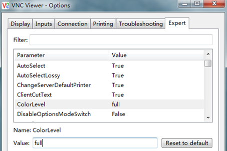
2. If VNC Viewer flashes to exit, please set the VNC configuration color level to full as shown in Figure 11.
a. Click Options on the login interface.
b. Click the Expert tab.
c. Select ColorLevel.
d. Set the value of ColorLevel to full.
Figure 11 Modifying ColorLevel
Logging in to the VM operating system
As a best practice to ensure VM security, change the default login password of the VM operating system.
After you use VNC Viewer to log in to the desktop of the VM, enter the username and password to log in to the VM operating system.
By default, the VM on the EPS gateway has two users, one of which is assigned the privileges of common users and the other is assigned the privileges of administrators. As a best practice, use the administrator to log in to the VM operating system.
· The username of the common user is admin and the password is admin.
· The username of the administrator is root and the password is root.
To log in to the VM operating system with the administrator account:
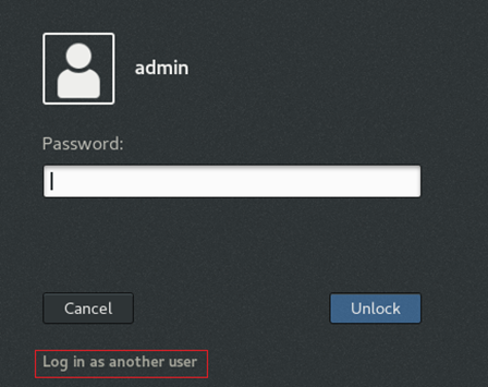
1. Click Log in as another user to use another user account to log in to the VM operating system, as shown in Figure 12. By default, the login page opens for user admin.
Figure 12 Using another user account to log in to the VM operating system
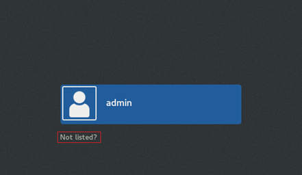
2. Click Not listed? as shown in Figure 13.
Figure 13 Selecting a login user
3. Enter the username and password of administrator root to log in to the VM operating system. (Details not shown.)
Configuring VM network settings
About this task
Perform this task to configure the IP address and gateway settings for the VM on the EPS gateway. Configure the default gateway address of the VM as the VLAN interface IP address of the VLAN to which the VM NIC belongs.
Procedure
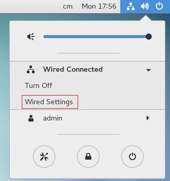
1. In the upper right corner of the desktop, select the Network Settings menu.
2. Select Wired Connected and click Wired Settings, as shown in Figure 14.
Figure 14 Opening the wired connection
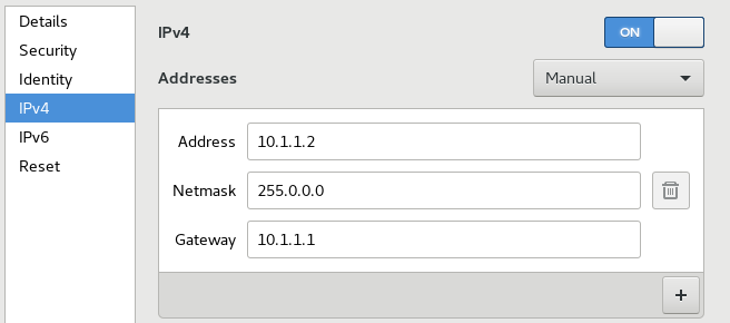
3. Configure IP address settings for the VM, as shown in Figure 15.
Figure 15 Configuring IP address settings
Verifying the configuration
To ensure a successful ping operation, make sure the firewall of the VM is disabled.
To ping the management host from the VM:
1. Right-click the desktop and select Open Terminal to enter the CLI of the CentOS system. The CLI is as shown in Figure 16.
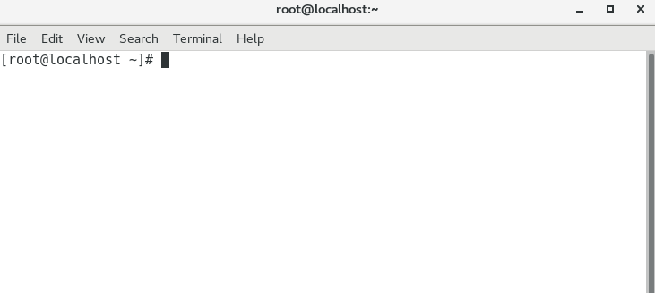
2. Stop the firewall on the VM.
[root@localhost~]# sudo systemctl stop firewalld
3. Verify that the VM can ping the management host. (Details not shown.)
Configuring the EPS scanner
Managing the EPS scanner
About this task
Perform this task to start or stop the EPS scanner. By default, the EPS scanner automatically starts up when the VM starts up.
Procedure
1. Display the running status of the EPS scanner.
[root@localhost~]# service EScanserver status
EScan is running
2. Perform one of the following tasks to start or stop the EPS scanner:
¡ Start the EPS scanner.
[root@localhost~]# service EScanserver start
¡ Stop the EPS scanner.
[root@localhost~]# service EScanserver stop
Specifying an EPS server for the EPS scanner
About this task
The built-in EPS scanner on the VM of the EPS gateway must cooperate with an EPS server installed with the H3C AD-EC controller. You can specify the IP address of the EPS server on the EPS scanner.
Procedure
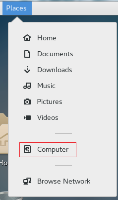
1. Select the Places menu in the left upper corner of the desktop, and then click Computer, as shown in Figure 17.
Figure 17 Opening the Computer option
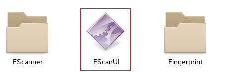
2. Find the EScan folder and open the folder. The folder path is opt/EScan, in which the folder name is case sensitive.
3. Open EScanUI in the opt/EScan/ directory as shown in Figure 18.
4. In the dialog box that opens, configure EPS server IP address settings. (Details not shown.)
5. Verify that the EPS server can deploy scanning tasks to the EPS gateway. (Details not shown.)
Verifying the functionalities of the EPS gateway
Verify that the EPS scanner on the VM of the EPS gateway can perform the following operations:
1. Receive scanning tasks from the EPS server.
2. Finish the tasks by scanning endpoints in the network.
3. Upload the scanned data to the EPS server.
Managing VMs
The built-in VM on the EPS gateway is installed in the root directory of disk sda1. The file saving path and hard disk path in the following examples both use the root directory of sda1. If external hard disk hda0 is inserted into the EPS gateway, you can specify a directory on sda1 or hda0 to save hard disk files and other files for the VM.
Starting the VM
1. Enter VMM view.
<H3C> system-view
[H3C] vmm
2. Start VM EScan.
[H3C-vmm] start vm EScan
Stopping the VM
About this task
Stopping the VM uses less than 6 minutes. If the VM cannot be normally stopped, you must use the stop command with the force keyword to forcibly stop the VM.
Procedure
1. Enter VMM view.
<H3C> system-view
[H3C] vmm
2. Stop VM EScan.
[H3C-vmm] stop vm EScan
Configuring VM auto-start
Restrictions and guidelines
If you enable or disable VM auto-start on the running VM, the configuration will take effect after you restart the VM.
If you enable or disable VM auto-start on the stopped VM, the configuration will take effect after you start the VM.
Procedure
1. Enter VMM view.
<H3C> system-view
[H3C] vmm
2. Enable VM auto-start on VM EScan.
[H3C-vmm] autostart vm EScan
3. Disable VM auto-start on VM EScan.
[H3C-vmm] undo autostart vm EScan
Backing up the VM
About this task
Perform this task to back up the VM in stopped state. The backup file is a .vmb file.
You can use a .vmb file to restore the VM when the VM fails.
Procedure
1. Enter VMM view.
<H3C> system-view
[H3C] vmm
2. Back up VM EScan to file sda1:/EScan.vmb.
[H3C-vmm] backup vm EScan sda1:/EScan.vmb
Restoring the VM
About this task
Perform this task to restore the VM from a .vmb backup file.
Procedure
1. Enter VMM view.
<H3C> system-view
[H3C] vmm
2. Restore the VM from file sda1:/EScan.vmb.
[H3C-vmm] restore pakagepath sda1:/EScan.vmb
Exporting the VM to a .pkg file
About this task
Perform this task to export the VM in stopped state to a .pkg file. You can use the .pkg file to redeploy the VM on the EPS gateway.
Procedure
1. Enter VMM view.
<H3C> system-view
[H3C] vmm
2. Export VM EScan to file sda1:/EScan.pkg.
[H3C-vmm] export vm EScan sda1:/EScan.pkg
Uninstalling the VM
About this task
Perform this task to uninstall the VM in stopped state.
Procedure
1. Enter VMM view.
<H3C> system-view
[H3C] vmm
2. Uninstall VM EScan.
[H3C-vmm] uninstall vm EScan
Adding a disk to the VM
Restrictions and guidelines
Before you add a disk to the VM, you must create the disk.
If you add disks to the running VM, you must restart the VM for the add operation to take effect.
If you add disks to the stopped VM, the add operation will take effect after you start the VM.
Procedure
1. Enter VMM view.
<H3C> system-view
[H3C] vmm
2. Create a VM disk.
create-disk disk-file size size format { raw | qcow2 }
3. Add the disk to the VM.
add disk vm vm-name format { raw | qcow2 } disk-file path-file disk-bus { ide | virtio }
For example:
# Enter VMM view.
<H3C> system-view
[H3C] vmm
# Create a disk. The disk file path is sda1:/EScan.qcow, the size is 30 GB, and the format is QCOW2.
[H3C-vmm] create-disk sda1:/EScan.qcow size 30 format qcow2
# Add the disk to VM EScan.
[H3C-vmm] add disk vm EScan format qcow2 disk-file sda1:/EScan.qcow disk-bus ide
Configuring VMs
For more information about configuring hard disks, vNICs, memory, vCPUs, and other parameters for the VM and the related commands, see the following manuals:
· VM configuration in Virtual Technologies Configuration Guide of H3C MSR810[2600][3600] Routers Configuration Guides.
· VM commands in Virtual Technologies Command Reference of H3C MSR810[2600][3600] Routers Command References.
Display and maintenance commands for VM management
Execute display commands in any view.
|
Command |
|
|
Display the VM list. |
display vmlist |
|
Display VM disk and CD-ROM information. |
display vmdisklist [ vm vm-name ] |
|
Display detailed VM information. |
display vm [ vm-name ] |
|
Display the number of CPUs allocated to the VM. |
display vcpu-pool |
|
Display VM CPU usage. |
display vmcpu-usage vm vm-name |
|
Display VM memory usage. |
display vmmem-usage vm vm-name |
|
Display SR-IOV NIC information. |
display sriov |
|
Display VM network interface information. |
display vminterface [ vm vm-name ] |
|
Display the VM VNC port number. |
display vncport vm vm-name |
|
Display the bindings between vCPUs and physical CPUs. |
display vmcpupin [ vm vm-name ] |
|
Display VM disk usage information. |
display vmdisk-usage vm vm-name |
|
Display physical NIC information. |
display passthrough |
|
Display the SR-IOV NIC network mode. |
display vm-network-mode |