- Table of Contents
-
- 16-High Availability Configuration Guide
- 00-Preface
- 01-VRRP configuration
- 02-Reth interface and redundancy group configuration
- 03-BFD configuration
- 04-Track configuration
- 05-Process placement configuration
- 06-Interface collaboration configuration
- 07-Monitor Link configuration
- 08-Interface backup configuration
- 09-RBM configuration
- 10-Smart Link configuration
- 11-Hot backup configuration
- Related Documents
-
| Title | Size | Download |
|---|---|---|
| 09-RBM configuration | 476.93 KB |
Contents
Configuration consistency check
Restrictions and guidelines: RBM configuration
Prerequisites for RBM configuration
Configuring the RBM control channel
Configuring the RBM data channel
Configuring the active/standby hot backup mode
Configuring the dual-active hot backup mode
Configuring RBM configuration synchronization
Setting the VRRP state switchover delay
Display and maintenance commands for RBM
Example: Configuring a VRRP hot backup system operating in active/standby mode
Example: Configuring a VRRP hot backup system operating in dual-active mode
Configuring RBM
About RBM
Remote Backup Management (RBM) provides backup for important configuration and service entries between devices. It can collaborate with VRRP to implement hot backup that enables smooth master/backup switchover upon link failures for service continuity. For more information about VRRP, see "Configuring VRRP." For more information about hot backup, see hot backup configuration.
Limitations of VRRP
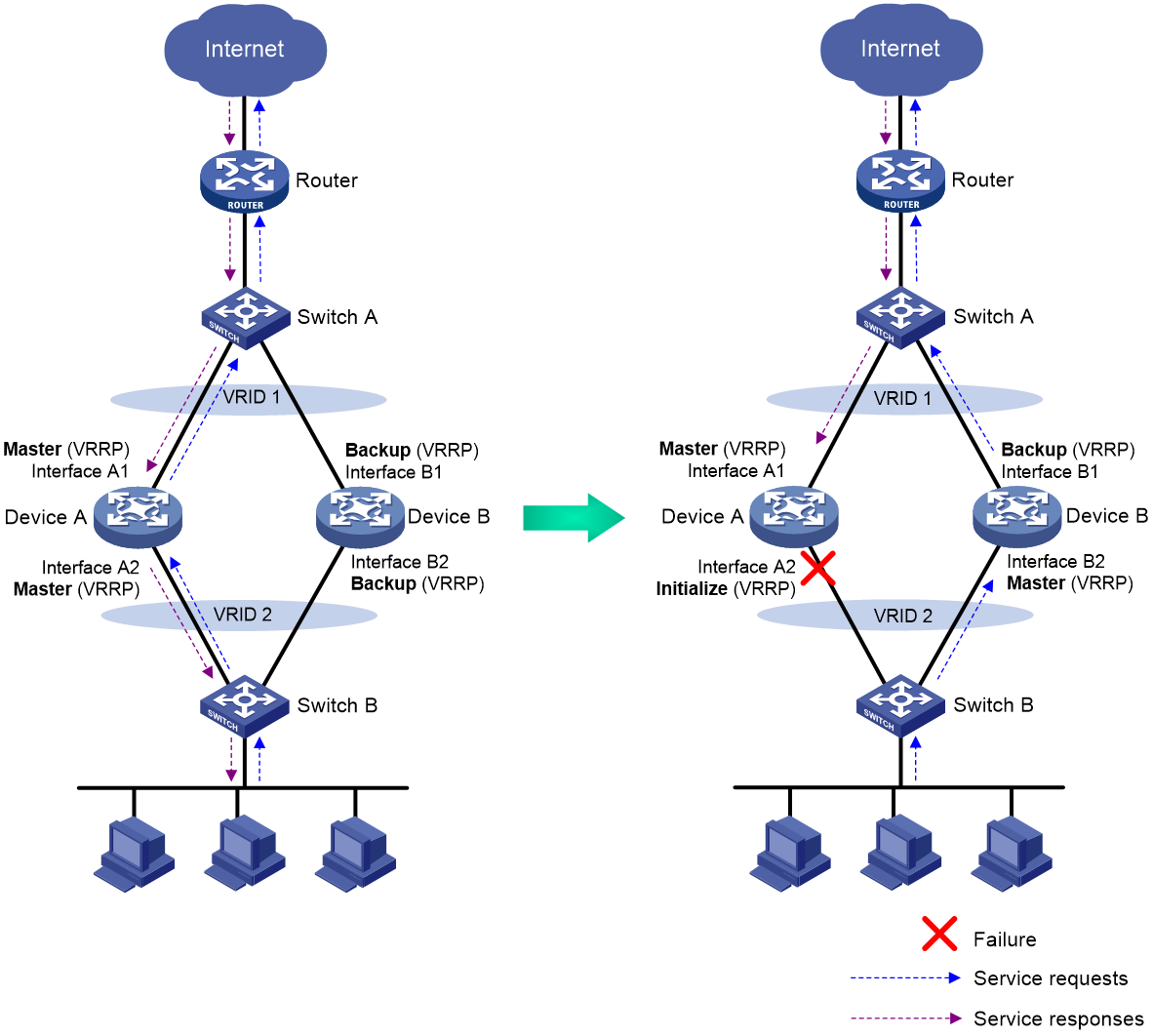
As shown in Figure 1, a traditional VRRP network can ensure high availability, but cannot resolve the following problems:
· Asymmetric forwarding path
Different VRRP groups on a device are independent of each other and cannot ensure that the traffic of a flow is forwarded and processed through the same device. As shown in Figure 1, when Interface A2 on Device A fails, Device A changes to Initialize state and Device B becomes the master in VRRP group 2. Because Interface A1 on Device A is operating correctly, Device A is still the master in VRRP group 1. As a result, the traffic sent from the PCs is distributed to Device B, but the return traffic sent from the Internet is distributed to Device A. Device A will drop the traffic because Interface A2 has failed.
· Configuration inconsistency
The devices in a VRRP group exchange only VRRP status information. They do not exchange important configuration information and service entries. Traditional network devices such as switches and routers require only device redundancy at Layer 2 and route backup to ensure service continuity. Services might be interrupted because of configuration inconsistency on security devices that perform status check and policy processing on packets, such as firewalls, IPSs, and network access behavior auditors.
Advantages of RBM
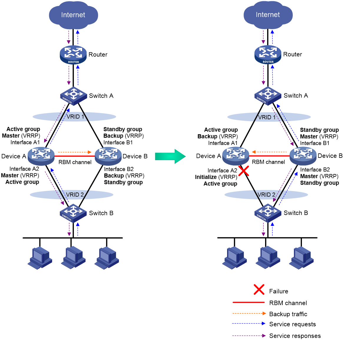
As shown in Figure 2, RBM can ensure symmetric forwarding and configuration consistency which cannot be provided by VRRP.
· RBM can centrally manage multiple VRRP groups on two devices to ensure that they have the same VRRP master and backup. As shown in Figure 2, when Interface A2 on Device A fails, RBM assigns the master role to Device B in both VRRP group 1 and VRRP group 2. In this way, the outbound traffic and return traffic will be forwarded and processed through the same device.
· RBM can synchronize important configuration and service entries between the master and the backup devices in VRRP groups.
Figure 2 Hot backup implemented by RBM-VRRP association
Basic concepts in RBM
Basic concepts in RBM are as follows:
· Remote backup group—Includes the two devices in a hot backup system. The remote backup group manages member switchover for multiple VRRP groups on the devices, and backs up important configuration and service entries.
· RBM primary and secondary roles—The primary and secondary roles are assigned to the two devices in a remote backup group to control the configuration synchronization between the devices.
· VRRP master and backup roles—Determine which device forwards and processes traffic in a VRRP group. The master and backup roles are assigned to the primary and secondary devices in a remote backup group, respectively. In a VRRP group, the master forwards traffic of services and backs up service entries to the backup in real time. When the master fails, the backup takes over the master role to ensure service continuity.
· VRRP active and standby groups—Associate RBM with VRRP for RBM to centrally manage the status of multiple VRRP groups.
· RBM channels—Transmit status information, important configuration, and service entries between the remote backup group members.
· Hot backup modes—Include active/standby mode and dual-active mode. In active/standby mode, the primary device processes all services. In dual-active mode, both devices process services to increase the capability of the hot backup system and load share traffic.
· RBM packets—Transmitted through TCP over the RBM channel between the remote backup group members.
RBM channels
Control channel and data channel
RBM transmits remote backup group status, important configuration, and service entries between the remote backup group members through the following channels:
· Control channel—Transmits data by using packets, including remote backup group status packets, configuration consistency check packets, and configuration synchronization packets.
· Data channel—Transmits only hot backup packets and packets that require transparent transmission. The data channel uses the hardware driver for data transmission and supports only Layer 2 forwarding.
Establishment and keepalive mechanism of the control channel
The control channel uses the keepalive mechanism of TCP for reachability detection. When detecting that the TCP connection is disconnected, RBM sends five consecutive reconnection requests to the peer end at intervals of one second. If all reconnection attempts fail, RBM disconnects the control channel.
Service entry backup
Overview
RBM backs up the service entries generated on the primary device to the secondary device to prevent service interruption when a primary/secondary member switchover occurs.
Security devices generate a session entry for each dynamic connection. In a remote backup group, only the primary device processes traffic and generates session entries. To ensure service continuity, the primary device backs up its session entries to the secondary device in real time. After a primary/secondary member switchover, the new primary device can forward the packets of the existing services based on the session entries without interruption.
Supported service entries
RBM can perform hot backup for the following service entries:
· Session entries.
· Session relation entries.
· NAT port blocks.
· Entries generated by security service modules.
Configuration backup
Overview
RBM backs up important configuration from the primary device to the secondary device to prevent service interruption when a primary/secondary member switchover occurs.
· When both devices are operating correctly, the primary device synchronizes configuration to the secondary device. The configuration on the secondary device is overwritten. As a best practice to ensure correct operation of RBM, enable configuration backup on the primary device.
· When one of the devices reboots, the device that completes reboot obtains configuration from the device that is not rebooted. The configuration on the rebooted device is overwritten.
RBM supports both automatic backup and manual backup.
Supported services
RBM can perform configuration backup for the following services:
· Resources—VPN instance, ACL, object group, time range, security zone, session management, APR, AAA, and NQA.
· DPI—Application layer inspection engine, IPS, URL filter, data filter, file filter, anti-virus, and data analysis center.
· Polices—Object policy, security policy, ASPF, attack detection and prevention, connection limit, NAT, AFT, load balancing, bandwidth management, application auditing and management, shared network access management, and proxy policy.
· Logs—Fast log output and flow log.
· VPN—SSL VPN.
Configuration consistency check
RBM verifies configuration consistency between the remote backup group members by using configuration consistency check packets. If a device detects configuration inconsistency, it generates a log for you to manually synchronize configuration.
Configuration consistency check operates as follows:
1. The primary device sends configuration consistency check packets to the secondary device and collects configuration digests of related modules at the same time.
2. The secondary device receives the packets, encapsulates its configuration digests into configuration consistency check packets, and sends these packets to the primary device.
3. The primary device compares its configuration digests with those of the secondary device. If inconsistency is detected, the primary device generates a log.
VRRP group management of RBM
Overview
As shown in Figure 3, VRRP cannot ensure symmetric forwarding upon failure on a device, which causes traffic interruption. RBM assigns Device A and Device B the same role in all VRRP groups configured on them, ensuring symmetric forwarding and service continuity.
You can associate RBM with VRRP by assigning the remote backup group members to the VRRP active group and VRRP standby group, respectively. After the RBM control channel is established, RBM determines the roles of the devices in all configured VRRP groups. The master election mechanism of VRRP no longer takes effect. If the RBM control channel is disconnected, the master election mechanism of VRRP takes effect again.
Figure 3 VRRP group management of RBM
VRRP active/standby group
A VRRP active/standby group can be in master or backup state, which determines the state of devices in the associated VRRP groups. For example, if a VRRP active group is in master state, all devices in the associated VRRP groups are masters.
The initial state of a VRRP active/standby group is depends on the hot backup mode.
· Active/Standby mode—On the primary device, the initial state is master for the VRRP active and standby groups. On the secondary device, the initial state is backup for the VRRP active and standby groups.
· Dual-active mode—The state of a VRRP active/standby group is not affected by the RBM roles. The initial state is master for the VRRP active group and is backup for the VRRP standby group.
VRRP master election in the RBM environment
After RBM is associated with VRRP, RBM determines the roles of the devices in the VRRP groups. As shown in Figure 3, Device A is the master in VRRP group 1 and VRRP group 2, and Device B is the backup in VRRP group 1 and VRRP group 2. When Interface A2 on Device A fails, the following events occur:
1. RBM receives an interface failure event and sends the status change information of the VRRP active and standby groups to Device B.
2. Device B sets its role to master in the VRRP standby group and then becomes the master in VRRP group 1 and VRRP group 2.
3. Device B sends a response to Device A after the master/backup switchover.
4. Device A sets its role to backup in the VRRP active group and then becomes the backup in VRRP group 1 and VRRP group 2.
When Interface A2 recovers, RBM performs another master/backup switchover following the same procedure. Traffic is switched back to Device A after the switchover.
VRRP hot backup mode
VRRP hot backup supports active/standby mode and dual-active mode.
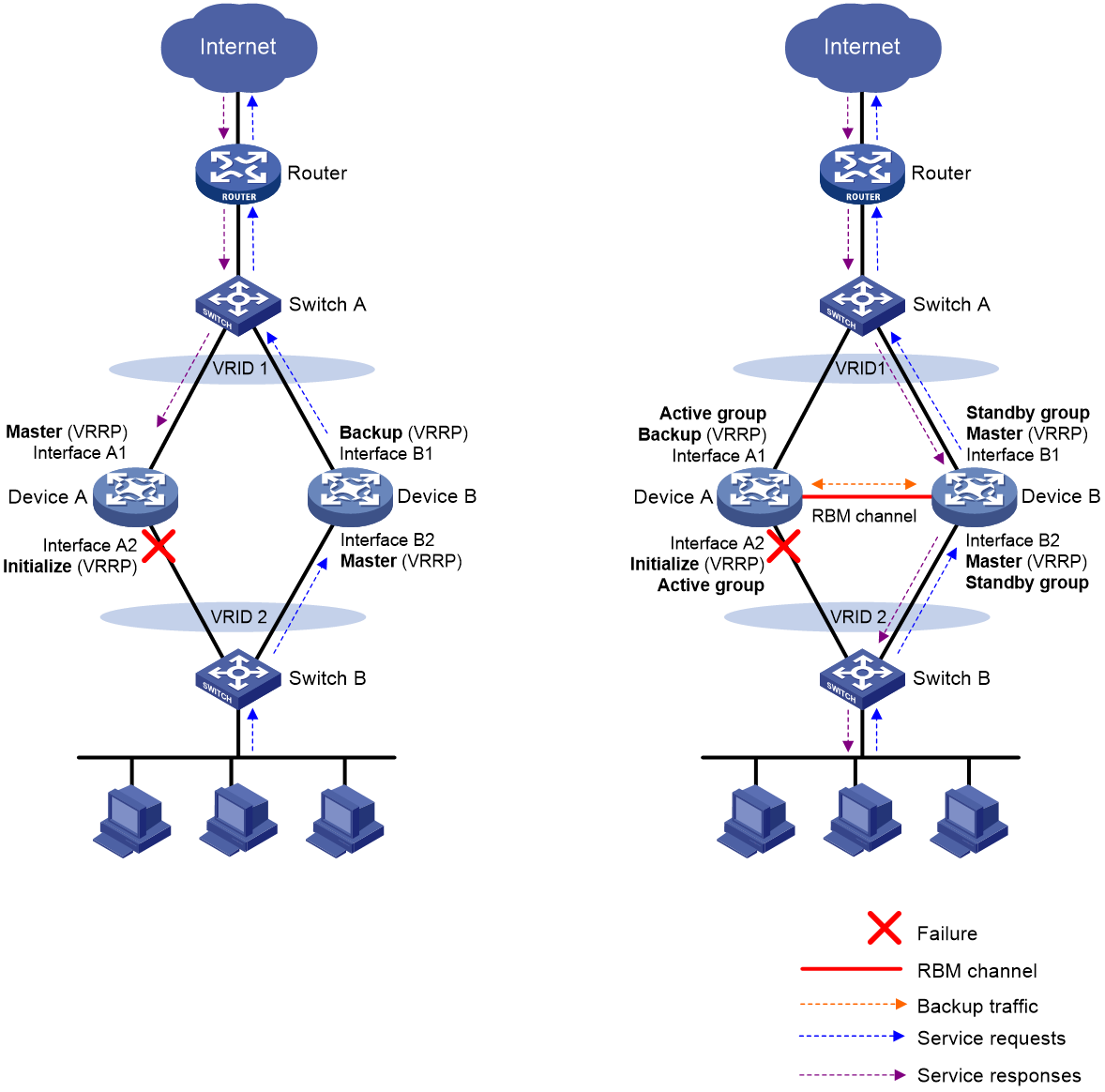
Active/standby mode
In active/standby mode, the primary device processes services, and the secondary device stands by. When failure occurs on the primary device, such as interface failure, link failure, and device failure, the secondary device takes over to process services.
As shown in Figure 4, to use the active/standby mode, perform the following tasks:
1. Create VRRP group 1 on the uplink interfaces of Device A and Device B.
2. Create VRRP group 2 on the downlink interfaces of Device A and Device B.
3. On Device A, associate VRRP group 1 and VRRP group 2 with the VRRP active group.
4. On Device B, associate VRRP group 1 and VRRP group 2 with the VRRP standby group.
5. Set the hot backup mode to active/standby.
6. Assign Device A and Device B to the remote backup group, and assign the primary role to Device A and secondary role to Device B.
Device A creates a session for a service when receiving the first packet of the service, and backs up the session entries to Device B in real time. When the downlink of Device A fails, Device B takes over the primary role, and the traffic that has been processed by Device A is switched to Device B without traffic loss. Then Device B creates sessions for new flows and backs up the session entries to Device A.
Figure 4 Active/standby mode of VRRP hot backup

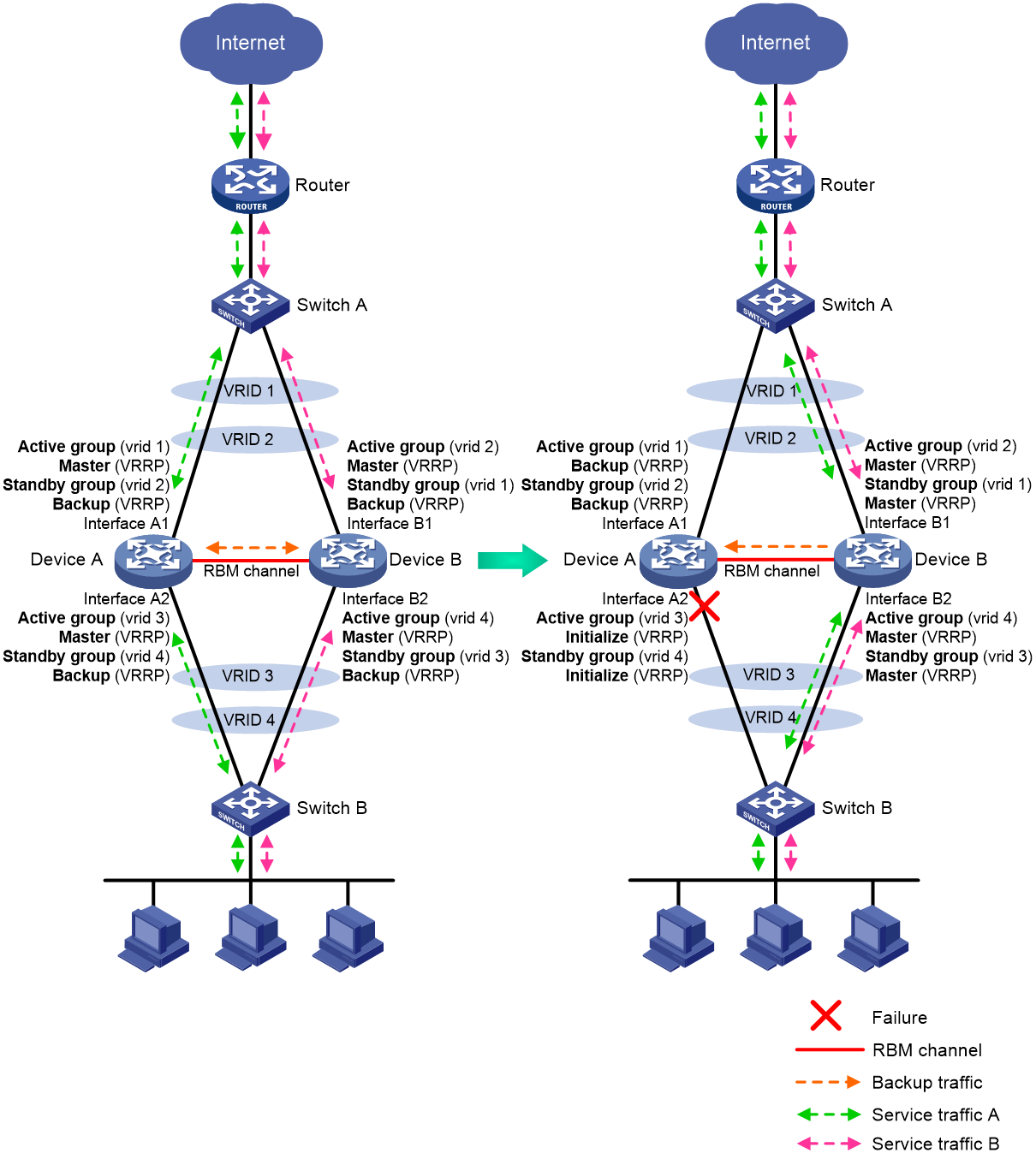
Dual-active mode
In dual-active mode, both devices process services to load share traffic and increase capability of the hot backup system. When one device fails, traffic is switched to the other device without traffic loss.
As shown in Figure 5, to use the dual-active mode, perform the following tasks:
1. Create VRRP group 1 and VRRP group 2 on the uplink interfaces of Device A and Device B.
2. Create VRRP group 3 and VRRP group 4 on the downlink interfaces of Device A and Device B.
3. On Device A, associate VRRP group 1 and VRRP group 3 with the VRRP active group, and associate VRRP group 2 and VRRP group 4 with the VRRP standby group.
4. On Device B, associate VRRP group 1 and VRRP group 3 with the VRRP standby group, and associate VRRP group 2 and VRRP group 4 with the VRRP active group.
5. Set the hot backup mode to dual-active.
6. Assign Device A and Device B to the remote backup group, and assign the primary role to Device A and secondary role to Device B.
In dual-active mode, Device A and Device B create sessions and back up their session entries to each other. When the downlink of Device A fails, Device B takes over the primary role, and the traffic that has been processed by Device A is switched to Device B without traffic loss. Then Device B creates sessions for new services and backs up the session entries to Device A.
Figure 5 Dual-active mode of VRRP hot backup
Restrictions and guidelines: RBM configuration
A remote backup group can contain a maximum of two devices.
The RBM-VRRP association requires configuration on two directly connected devices. For each device, uplink and downlink devices must be Layer 2 devices.
RBM applies only to VRRP standard mode. VRRP load sharing mode does not support RBM.
As a best practice, add the primary device to the VRRP active group and the secondary device to the VRRP standby group.
Prerequisites for RBM configuration
Before you configure RBM, verify that the following hardware and software settings are the same on the devices to be assigned to a remote backup group:
· Device model.
· Software version.
· IRF member ID.
· Interface for setting up the control channel.
· Interface for setting up the data channel.
· Security zone configuration on the interfaces with the same slot number.
· Location, number, and type of service modules.
· Location, number, and type of interface modules.
RBM configuration flow
Figure 6 shows the configuration flow of RBM.
Figure 6 RBM configuration flow chart
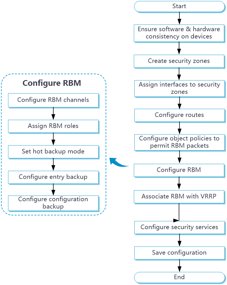
RBM tasks at a glance
To configure RBM, perform the following tasks:
1. Configuring the RBM control channel
2. Configuring the RBM data channel
4. Configuring the hot backup mode for RBM
Choose one of the following tasks:
¡ Configuring the active/standby hot backup mode
¡ Configuring the dual-active hot backup mode
6. Configuring RBM configuration synchronization
8. (Optional.) Setting the VRRP state switchover delay
Configuring the RBM control channel
About this task
RBM compares the specified local and peer IP address to determine the device role for setting up the control channel. The device with higher IP address acts as the server to listen for TCP connection requests, and the other device acts as the client to initiate the TCP connection.
If the port number is configured on the server, the port provides services for the client. If the port number is configured on the client, the port serves as the destination port to establish TCP connection to the server. The source port is randomly generated on the client.
Restrictions and guidelines
You can specify only one peer IP address with the same port number on the primary and secondary devices. The specified port cannot be the same as the TCP listening port in use.
Procedure
1. Enter system view.
system-view
2. Enter remote backup group view.
remote-backup group
3. Configure the peer IP address for setting up the RBM control channel.
remote-ip ip-address [ port port-number ]
By default, the peer IP address is not configured.
4. Configure the local IP address for setting up the RBM control channel.
local-ip ip-address
By default, the local IP address is not configured.
Configuring the RBM data channel
About this task
RBM can use the same physical interface or different physical interfaces for setting up the RBM data channel and control channel.
Perform this task to set up a dedicated data channel that transmits only hot backup packets and the packets that require transparent transmission. This ensures that the packets are not interrupted by other packets transmitted between the primary and secondary devices and saves link bandwidth.
Procedure
1. Enter system view.
system-view
2. Enter remote backup group view.
remote-backup group
3. Configure an RBM data channel.
data-channel interface interface-type interface-number
By default, no RBM data channel is configured.
Configuring the RBM role
About this task
RBM backs up important configuration from the primary device to the secondary device to prevent service interruption when a primary/secondary member switchover occurs. The configuration on the secondary device is overwritten. The unidirectional backup mechanism avoids configuration conflicts, especially in dual-active mode. The RBM roles can only be manually assigned to devices.
Restrictions and guidelines
You must assign the primary and secondary roles to the two member devices in a VRRP hot backup system, respectively.
As a best practice to ensure correct operation of RBM, enable configuration backup on the primary device.
Procedure
1. Enter system view.
system-view
2. Enter remote backup group view.
remote-backup group
3. Configure the RBM role.
device-role { primary | secondary }
By default, the RBM role is not configured.
Configuring the active/standby hot backup mode
1. Enter system view.
system-view
2. Enter remote backup group view.
remote-backup group
3. Configure the active/standby hot backup mode.
undo backup-mode dual-active
By default, the hot backup mode is active/standby.
Configuring the dual-active hot backup mode
1. Enter system view.
system-view
2. Enter remote backup group view.
remote-backup group
3. Configure the dual-active hot backup mode.
backup-mode dual-active
By default, the hot backup mode is active/standby.
Enabling RBM hot backup
About this task
Perform this task to enable the primary device in the remote backup group to back up service entries to the secondary device in real time.
Procedure
1. Enter system view.
system-view
2. Enter remote backup group view.
remote-backup group
3. Enable RBM hot backup.
hot-backup enable
By default, RBM hot backup is enabled.
Configuring RBM configuration synchronization
About this task
The automatic configuration synchronization feature synchronizes existing configuration on the primary device in bulk to the secondary device. Consequent synchronization for added, deleted, or modified configuration will be performed in real time.
Restrictions and guidelines
If the amount of configuration to be synchronized is large, bulk synchronization might take one to two hours. To avoid the issue, you can perform one of the following operations:
· Enable automatic configuration synchronization first when you configure RBM.
· Copy the configuration file to the secondary device during initial network deployment and then enable configuration consistency check.
Procedure
1. Enter system view.
system-view
2. Enter remote backup group view.
remote-backup group
3. Enable automatic configuration synchronization.
configuration auto-sync enable
By default, automatic configuration synchronization is disabled.
4. Enable configuration consistency check.
configuration sync-check [ interval interval ]
By default, configuration consistency check is disabled.
5. (Optional.) Manually synchronize the configuration of the primary device to the secondary device.
configuration manual-sync
For manual configuration synchronization to take effect, you must first enable automatic configuration synchronization.
Associating RBM with VRRP
1. Enter system view.
system-view
2. Enter interface view.
interface interface-type interface-number
3. Create an IPv4 VRRP group and associate it with RBM.
vrrp vrid virtual-router-id virtual-ip virtual-address { active | standby }
By default, no IPv4 VRRP groups exist.
For more information about this command, see High Availability Command Reference.
Setting the VRRP state switchover delay
About this task
Perform this task to set the delay that the primary and secondary devices must wait before a switchback. This delay ensures that the devices can finish service entry backup to prevent traffic loss.
Procedure
1. Enter system view.
system-view
2. Enter remote backup group view.
remote-backup group
3. Set the VRRP state switchover delay.
vrrp delay-time [ delay-time ]
By default, the VRRP state switchover delay is one minute.
Display and maintenance commands for RBM
Execute display commands in any view.
|
Task |
Command |
|
Display remote backup group status information. |
display remote-backup-group status |
|
Display the configuration consistency check result for the remote backup group. |
display remote-backup-group sync-check |
RBM configuration examples
Example: Configuring a VRRP hot backup system operating in active/standby mode
For more information about this configuration example, see "Configuring VRRP hot backup."
Example: Configuring a VRRP hot backup system operating in dual-active mode
For more information about this configuration example, see "Configuring VRRP hot backup."