- Table of Contents
- Related Documents
-
| Title | Size | Download |
|---|---|---|
| 01-EPON configuration | 741.94 KB |
EPON port types and port numbering rules
Multicast in IGMP snooping mode
Multicast in multicast control mode
Restrictions and guidelines: OLT configuration
Setting the ONU authentication mode
Configuring the OLT operating mode
Changing the type of fiber interfaces
Setting the link type of an OLT port
Setting the link type of an OLT port to hybrid
Setting the link type of an OLT port to trunk
Setting the link type of an OLT port to access
Enabling compatibility with third-party ONUs
Enabling grant filtering on an OLT port
Setting the processing mode for frames with an invalid source MAC address
Setting the LLID key update interval
Setting the maximum ONU-OLT RTT
Setting the timeout timer for extended OAM discovery
Setting the maximum number of ONU E1/UNI/VoIP ports that can be queried by SNMP
Display and maintenance commands for the OLT
Fiber backup configuration example
Restrictions and guidelines: ONU configuration
Enabling ONU user authentication
Restrictions and guidelines for ONU bindings
Enabling automatic ONU binding
Enabling ONU binding control on OLT ports
Setting the aging timer for dynamic MAC address entries for an ONU
Configuring the management VLAN of an ONU
Setting the link type of an ONU port and assigning the port to VLANs
About VLAN configuration of ONU ports
Configuring an ONU port as an access port and assigning the port to a VLAN
Configuring an ONU port as a trunk port and assigning the port to VLANs
Enabling user network management features on an ONU
Configuring the loop protection action
Setting the multicast mode of an ONU
Configuring ONU bandwidth allocation and related parameters
Configuring congestion management for uplink ONU traffic
Configuring CoS-to-local priority mappings
Configuring priority marking on a UNI
Configuring traffic policing on a UNI
Setting the state of the transmit power supply for transceiver modules of ONU PON ports
Enabling UNI count-based PON port activation for an ONU
Enabling an ONU to send flush messages
Enabling packet statistics for an ONU
Enabling event reporting for an ONU
Enabling downlink traffic encryption for an ONU
Bringing up a VoIP interface on an ONU
Configuring basic settings of UNIs
Setting the MAC learning limit on a UNI
Setting the VLAN operation mode for a UNI
Enabling fast-leave processing for a UNI
Configuring UNI port isolation
Enabling unknown multicast packet transparent transmission for UNIs
Configuring port mirroring on a UNI
Enabling packet statistics for a UNI
Testing the cable connected to a UNI
Configuring ONU serial interfaces
Display and maintenance commands for ONUs
ONU binding configuration example
ONU user authentication configuration example
Multicast in IGMP snooping mode configuration example
Multicast in multicast control mode configuration example
ONU update configuration example
Configuring an OLT as a BCMP proxy
Appendix: Support for non-EPON features and configuration restrictions
OLT port features and restrictions
Commands unavailable in OLT port view
ONU port features and restrictions
Commands unavailable in ONU port view
EPON overview
Ethernet Passive Optical Network (EPON) is a Passive Optical Network (PON) that carries Ethernet frames encapsulated in 802.3 standards. EPON is a combination of Ethernet technology and PON technology in compliance with the IEEE 802.3ah standards issued in June 2004.
EPON architecture
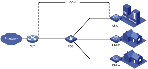
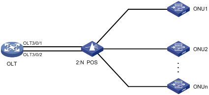
As shown in Figure 1, a typical EPON system contains optical line terminals (OLTs), optical network units (ONUs), and optical distribution networks (ODNs).
· OLT—The core device of an EPON system, located at the central office. The OLT manages ONUs in the EPON system and forwards traffic between the EPON system and the IP network.
· ONU—A device connected to customer premises equipment such as PCs, set-top boxes, and switches. Typically, ONUs are placed at customers' homes, corridors, or roadsides. ONUs forward uplink data sent by customer premises equipment (from ONU to OLT) and selectively forward downlink broadcasts sent by OLTs (from OLT to ONU).
· ODN—A network formed by optical fibers, one or multiple passive optical splitters (POSs), and other passive optical components. ODNs provide optical signal transmission paths between OLTs and ONUs. A POS can couple uplink data into a single piece of fiber and distribute downlink data to ONUs.
EPON uses the single-fiber wavelength division multiplexing (WDM) technology to implement single-fiber bidirectional transmission. WDM uses a downlink central wavelength of 1490 nm and an uplink central wavelength of 1310 nm. WDM can support a transmission distance of up to 20 km (12.43 miles).
Figure 1 Typical EPON architecture
Working mechanisms
An EPON system must complete ONU registration, extended OAM connection establishment, and bandwidth allocation before it can transmit data.
ONU registration
EPON uses the following types of Multipoint Control Protocol (MPCP) messages for ONU registration:
· GATE messages, including:
? Discovery GATE message, broadcasted by the OLT to discover ONUs.
? General GATE message, unicasted by the OLT to allocate bandwidth to ONUs.
· REGISTER_REQ message.
· REGISTER message.
· REGISTER_ACK message.
Each of these messages contains a timestamp field that records the local clock at the time of packet transmission.
An ONU can register with an OLT by using its MAC address, logical ONU identifier (LOID), or LOID and LOID password. An ONU is registered by using the following workflow when its MAC address is used for registration:
1. An OLT broadcasts a discovery GATE message to notify the start time and length of the discovery timeslot to all ONUs.
2. An unregistered ONU receives the discovery GATE message and sets its local clock to be the same as the timestamp contained in the message. When the local clock reaches the start time, the ONU sends a REGISTER_REQ message to the OLT after a random delay. The REGISTER_REQ message contains the MAC address of the ONU and the local timestamp of the ONU when the message is sent.
3. The OLT receives the REGISTER_REQ message and obtains the MAC address of the ONU and ONU-OLT round trip time (RTT). The ONU-OLT RTT is mainly used for time synchronization between an OLT and ONUs.
4. The OLT parses the REGISTER_REQ message, and uses the MAC address in the message to unicast a REGISTER message to the ONU. The REGISTER message contains a logical link ID (LLID) assigned to the ONU as a unique identifier.
5. The OLT sends a general GATE message to the same ONU immediately after sending the REGISTER message.
6. The ONU receives the REGISTER message and general GATE message. Then, the ONU sends a REGISTER_ACK message in the timeslot assigned in the GATE message to notify the OLT that the REGISTER message is parsed successfully.
ONU registration is completed.
Extended OAM connection establishment
EPON supports Ethernet Operation, Administration and Maintenance (OAM) and extended OAM functions. Ethernet OAM is a network monitoring tool that operates at the data link layer. It reports link status by periodically exchanging OAMPDUs between devices for administrators to effectively manage the network. Extended OAM uses both basic OAMPDUs and extended OAMPDUs for OLTs and ONUs to establish connections and implement remote management.
An extended OAM connection is established by using the following workflow:
1. An OLT and an ONU establish a standard OAM connection.
2. The ONU reports the supported organizationally unique identifier (OUI) and extended OAM version number to the OLT.
3. The OLT identifies whether the OLT supports the reported OUI and extended OAM version number.
? If the OLT supports the reported OUI and extended OAM version, the extended OAM connection for the ONU is established successfully.
? If the reported OUI and extended OAM version are not supported, the extended OAM connection cannot be established.
Bandwidth allocation
After the extended OAM connection is established, downlink data transmission can begin. Uplink data transmission can begin only after uplink bandwidth is allocated.
An OLT allocates uplink bandwidth to an ONU by using the following workflow:
1. The OLT sends a general GATE message to assign a transmission timeslot to the ONU.
2. The ONU sends a REPORT message to report the local status information such as buffer usage to the OLT. The OLT assigns timeslots intelligently based on the local status information of ONUs.
3. The OLT receives the REPORT message, and sends a general GATE message to assign the ONU a data transmission timeslot based on the current bandwidth.
4. The ONU receives the GATE message and transmits data at the transmission start time contained in the message.
Data transmission
EPON transmits uplink data and downlink data differently.
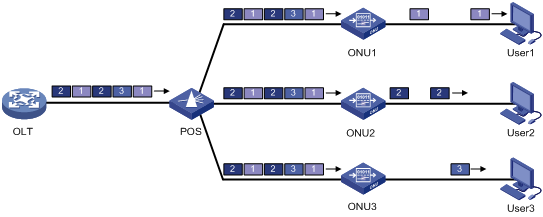
· Downlink data transmission—As shown in Figure 2, the OLT broadcasts downlink data to ONUs. Each ONU receives packets destined for it based on the LLID and drops the other packets.
Figure 2 Downlink data transmission in an EPON system
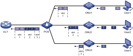
· Uplink data transmission—As shown in Figure 3, each ONU buffers the data frames received from users and sends the frames at the full wire-speed when the timeslot for the ONU arrives.
EPON uses the Time Division Multiple Access (TDMA) technology to transmit uplink data. This technology ensures that one optical fiber between the OLT and the POS can transmit data signals from multiple ONUs to the OLT without signal interference.
Figure 3 Uplink data transmission in an EPON system
EPON port types and port numbering rules
As shown in Figure 4, EPON defines the following port types:
· OLT port—A physical ONU-facing port on an OLT. Each OLT port on an EPON card acts as an independent OLT device.
OLT ports are numbered in the format of EPON card slot number/subcard slot number/OLT port number, for example, OLT 3/0/1.
· ONU port—A virtual port created on an OLT port.
ONU ports are numbered in the format of EPON card slot number/subcard slot number/OLT port number:ONU port number, for example, ONU 3/0/1:1.
Each ONU port corresponds to a physical ONU. The configuration performed in ONU port view takes effect on the ONU bound to the ONU port. An ONU port can identify an ONU only after the port is bound to the ONU.
· UNI—User network interface, a physical user-facing port on an ONU.
UNIs can be remotely configured and managed by executing commands in ONU port view.
Figure 4 EPON port types and port numbers
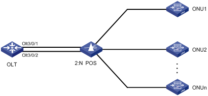
EPON system reliability
To ensure high reliability for the trunk fibers and OLTs in an EPON system, you can assign two OLT ports to a fiber backup group. The two OLT ports can reside on one EPON card or on two different EPON cards. The OLT port assigned first acts as the master port, and the other OLT port acts as the subordinate port. Only the master OLT port forwards traffic.
When a system fault occurs (for example, the trunk fiber of the master port is disconnected or the master port goes down), an automatic master/subordinate switchover is performed. Alternatively, you can perform a manual master/subordinate switchover. Figure 5 shows a fiber backup group, where the POS is a 2:N optical splitter.
ONU multicast mode
EPON supports the IGMP snooping mode and multicast control mode for ONUs. For more information about IGMP snooping, see IP Multicast Configuration Guide.
Multicast in IGMP snooping mode
In IGMP snooping mode, the OLT and ONUs mainly use IGMP report, leave, and query messages to manage dynamic multicast group membership. The OLT can implement simple user multicast access control through the multicast VLAN configuration on UNIs of ONUs.
When an ONU receives an IGMP membership report from a multicast group member, the ONU forwards the message to the OLT. When multiple members of a multicast group are attached to the ONU, the OLT will receive duplicate IGMP reports from these members. To reduce IGMP reports, enable IGMP report suppression. Within each query cycle, the ONU forwards only the first IGMP report of a multicast group to the OLT. Subsequent IGMP reports from the same multicast group are not forwarded.
On the OLT, you can configure the router port aging timer, the multicast group member port aging timer, and the query response timer for an ONU.
· Router port aging timer—The router port is the port that connects the ONU to the router. The ONU receives IGMP general query messages from the router through this port. If no IGMP general query message is received through the router port when the router port aging timer expires, the ONU determines that the port is not a router port. The router port aging timer must be a value about 2.5 times of the general query interval. For more information about the general query interval, see IGMP in IP Multicast Configuration Guide.
· Multicast group member port aging timer—This timer determines how often multicast group members are refreshed. If the ONU does not receive an IGMP report from a multicast group member port when this timer expires, the ONU deletes the port. In a network where multicast group members change frequently, set this timer to a small value.
· Query response timer—This timer sets the response timeout time for group-specific queries. If the ONU does not receive a response before the query response timer expires for the first time, it re-sends group-specific queries and re-starts the query response timer. If the ONU still does not receive a response when the timer expires, the multicast group on the ONU is deleted.
Multicast in multicast control mode
In multicast control mode, the OLT performs the following operations:
· The OLT maintains an access control table for user multicast services to centrally manage user multicast service access rights.
· The OLT identifies users based on the user LLID and the VLAN tag (same as the UNI number) carried in uplink IGMP report messages. The OLT also determines whether a user has the right to access the requested multicast service and determines the related parameters.
· The OLT uses extended multicast control OAM packets to send the ONU a user's access right to a multicast channel. This allows the ONU to forward or shut off the multicast traffic for the user. The network management system on the OLT centrally manages multicast access control. Multicast right management is governed by the OLT and executed by ONUs. The OLT also supports the cooperation between IGMP proxy and upper-layer multicast routers to dynamically request and deliver multicast traffic.
In multicast control mode, an ONU performs the following operations:
· The ONU maintains a table for multicast address filtering and multicast forwarding. The ONU performs flow control only for the current multicast service on the ONU.
· The ONU adds VLAN tags to untagged IGMP report and leave messages to identify users and transparently sends the messages to the OLT. The VLAN tag ID is the same as the UNI number. For example, the packets received on UNI 1 are tagged with VLAN ID 1. The ONU adds or deletes the group address filtering and multicast forwarding entries on the ONU based on the multicast control OAM packets delivered by the OLT. The multicast control OAM packets contain a series of multicast control entries. Based on the action taken on the entries, the ONU forwards or shuts off multicast traffic.
EPON QoS
Figure 6 shows the QoS model of an EPON system.
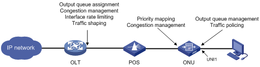
This section describes QoS features for an ONU. For information about QoS features on an OLT, see "OLT port features and restrictions."
An ONU supports the following QoS features:
· Congestion management for uplink ONU traffic
By configuring Service Level Agreement (SLA) attributes, you can remotely manage the fixed bandwidth, guaranteed bandwidth, and best-effort bandwidth for each queue on an ONU. During each DBA scheduling cycle, the ONU granularly manages the uplink bandwidth for each queue according to the uplink traffic queue scheduling configuration of the ONU and the DBA configuration on the OLT.
The following queue scheduling modes are supported:
? SP—Strict priority queueing, which classifies the eight output queues into eight classes, 7, 6, 5, 4, 3, 2, 1, and 0, in descending order of priority.
? WRR—Weighted round robin, which schedules queues according to their weights in a round robin way. WRR guarantees certain service time for each queue.
? SP+WRR—Uses SP and WRR together to schedule queues.
For more information about SP and WRR, see hardware congestion management configuration in ACL and QoS Configuration Guide.
· CoS-to-local priority mapping
When an ONU receives downlink traffic from an ONU port of an OLT, the ONU assigns the traffic to different output queues based on CoS-to-local priority mappings.
· UNI priority marking
Priority marking enables an ONU to perform the following operations on packets received from a UNI:
a. Classifies packets received from a UNI into multiple classes based on information of the packets, such as MAC addresses and IP addresses.
b. Applies different priority mapping policies to packets of different classes.
· UNI traffic policing
Traffic policing allows ONUs to evaluate traffic and limit the traffic rate. Traffic evaluation is implemented through the token bucket mechanism.
The token bucket mechanism evaluates traffic by checking the number of tokens in the bucket.
? If the number of tokens in the bucket is enough for forwarding the packets, the traffic conforms to the specification (called conforming traffic).
? If the number of tokens is not enough, the traffic does not conform to the specification (called excess traffic).
A token bucket has the following parameters:
? Committed information rate (CIR)—Rate at which tokens are put into the bucket, or the permitted average rate of traffic.
? Committed burst size (CBS)—Burst size or the capacity of the token bucket. It is the maximum traffic size permitted in each burst. The burst size must be greater than the maximum packet size.
? Excess Burst Size (EBS). For more information, see ACL and QoS Configuration Guide.
? Peak Information Rate (PIR). For more information, see ACL and QoS Configuration Guide.
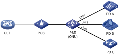
EPON PoE
On an OLT, you can remotely configure PoE for ONUs.
As shown in Figure 7, the PoE model of the EPON system includes the following elements:
· PSE—A power sourcing equipment (PSE) is an ONU that supplies power to PDs through UNIs.
· PD—A powered device (PD) receives power from a PSE. PDs include IP telephones and APs.
Figure 7 EPON PoE model
BCMP
Broadband-access-network Cluster Management Protocol (BCMP) uses a BCMP server to centrally manage an EPON system as a management domain.
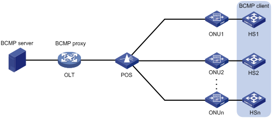
BCMP architecture
As shown in Figure 8, a BCMP system contains the following components:
· BCMP server—Master management server in a BCMP system. The BCMP server performs registration, configuration, management, and monitoring for members in the BCMP system.
· BCMP proxy—Proxy management server in a BCMP system. The BCMP proxy forwards member registration information and configuration between the BCMP server and BCMP clients.
· BCMP client—Member network elements in a BCMP system. BCMP clients are high-performance (HS) switches connected to ONUs or ONUs integrated with HS. The BCMP server centrally manages the BCMP clients through the BCMP proxy.
Figure 8 BCMP system architecture
Working mechanism
The BCMP server registers and configures a BCMP client by using the following procedure:
1. The BCMP client sends a registration request that contains its MAC address to the BCMP server.
2. The ONU connected to the BCMP client adds the UNI number of the client to the request, and forwards the request to the BCMP proxy (OLT).
3. The OLT performs the following operations:
a. Extracts the client MAC address and UNI number from the request.
b. Adds the ONU MAC address when re-encapsulating the request.
c. Sends the request to the BCMP server.
4. The BCMP server performs the following operations:
a. Extracts information from the request.
b. Creates a physical status entry for the BCMP client.
c. Sends the BCMP proxy the configuration for the client, including the management VLAN, management IP address, default gateway, and SNMP settings.
5. The BCMP proxy forwards the configuration to the BCMP client.
Configuring an OLT
Restrictions and guidelines: OLT configuration
This section lists only OLT tasks. For non-EPON features supported by the device, see "OLT port features and restrictions."
EPON is supported only on the default MDC. For more information about MDCs, see Virtual Technologies Configuration Guide.
The device supports the following EPON cards:
· 10G-EPON: LSQM1XPT12TSFD0 interface card.
10G-EPON cards support the following types of ONUs:
? 1G-EPON ONU: The downlink bandwidth and uplink bandwidth of EPON interfaces of the ONU are both 1 Gbps.
? 10G/1G-EPON ONU: The downlink bandwidth and uplink bandwidth of EPON interfaces of the ONU are both 10 Gbps and 1 Gbps, respectively.
? 10G/10G-EPON ONU: The downlink bandwidth and uplink bandwidth of EPON interfaces of the ONU are both 10 Gbps.
· 1G-EPON cards:
? LSQM1PT8TSSC0 interface card.
? LSQM1PT24TSSC0 interface card.
1G-EPON cards support only 1G-EPON ONUs.
On a 10G-EPON card, the total downlink bandwidth and the total uplink bandwidth of all 1G-EPON ONUs connected to each OLT port cannot exceed 1 Gbps separately.
The device does not support connecting to a DHCP server through an OLT port.
For more information about commands not supported by OLT ports, see "Commands unavailable in OLT port view."
OLT tasks at a glance
All OLT configuration tasks are optional.
To configure an OLT, perform the following tasks:
· Setting the ONU authentication mode
· Configuring the OLT operating mode
· Changing the type of fiber interfaces
· Setting the link type of an OLT port
· Enabling compatibility with third-party ONUs
· Enabling grant filtering on an OLT port
Perform this task to ensure correct data transmission.
· Setting the processing mode for frames with an invalid source MAC address
· Tuning EPON system parameters
? Setting the LLID key update interval
? Setting the maximum ONU-OLT RTT
? Setting the timeout timer for extended OAM discovery
? Setting the maximum number of ONU E1/UNI/VoIP ports that can be queried by SNMP
Perform this task to enable an OLT to record basic access information of users.
Setting the ONU authentication mode
About the ONU authentication mode
An OLT supports the following ONU authentication modes:
· MAC mode—Authenticates ONUs based on the MAC address.
· LOID mode—Authenticates ONUs based on the LOID.
· LOID-password mode—Authenticates ONUs based on the LOID and LOID password.
Restrictions and guidelines
You can set the ONU authentication mode in OLT port view or in FTTH view. If you set this mode in OLT port view, the configuration takes effect only on the OLT port. If you set this mode in FTTH view, the configuration takes effect on all OLT ports. An OLT port preferentially uses the port-specific ONU authentication mode. If no port-specific ONU authentication mode is available, the OLT port uses the ONU authentication mode configured in FTTH view.
You can configure multiple ONU authentication mode settings. The LOID mode and the LOID-password mode are mutually exclusive.
Procedure
|
Step |
Command |
Remarks |
|
1. Enter system view. |
system-view |
N/A |
|
2. Enter FTTH view or OLT port view. |
· Enter FTTH view: · Enter OLT port view: |
N/A |
|
3. Set the ONU authentication mode. |
authentication-mode { mac | loid | loid-password } * |
By default, an OLT port uses the MAC mode for ONU authentication. |
Configuring the OLT operating mode
About OLT operating modes
10G-EPON cards support the following OLT operating modes:
· 64-ONU mode—Each OLT port supports creating up to 64 ONU ports.
· 128-ONU mode—Each OLT port supports creating up to 128 ONU ports.
Restrictions and guidelines
After you change the OLT operating mode for a slot, you must reboot the slot or the whole device to make the OLT operating mode change take effect.
· If the slot is rebooted, all OLT ports in the slot are restored to the default settings, and the ONU ports created on the OLT ports are deleted.
· If the whole device is rebooted and the running configuration is saved, ONU ports numbered from 1 to 64 and OLT ports are not affected. When the OLT operating mode is changed from 128-ONU to 64-ONU, ONU ports numbered more than 64 are deleted.
Procedure
|
Step |
Command |
Remarks |
|
1. Enter system view. |
system-view |
N/A |
|
2. Enter FTTH view. |
ftth |
N/A |
|
3. Set the OLT operating mode for the specified slot. |
In standalone mode: In IRF mode: |
By default, the OLT operating mode is 64-ONU. |
Changing the type of fiber interfaces
About changing the fiber interface type
You can configure the EPON fiber interfaces on the LSQM1PT24TSSC0 interface card as OLT ports or GigabitEthernet interfaces.
Restrictions and guidelines
The fiber interfaces on the LSQM1PT24TSSC0 interface card are grouped by port number in order, starting from 1. Each group contains four interfaces. To change the type of an interface in a group, you must change the type of all the four interfaces in the group. For the interface type change to take effect, reboot the interface card.
If you change the type of an interface, the system automatically removes the original interface and then creates the target interface with the same number as the original interface.
When you use a GigabitEthernet interface that is changed from an OLT port, follow these restrictions and guidelines:
· The interface does not support jumbo frames larger than 2043 bytes. As a best practice, set the permitted jumbo frame length of the interface to 2043 bytes or a smaller value by using the jumboframe enable command.
· The interface does not support the following commands in Interface Command Reference:
? duplex
? eee enable
? flow-control
? flow-control receive enable
? loopback
? mdix-mode
? port up-mode
? speed
· The interface does not support a 100-Mbps optical transceiver module.
· For the peer interface to come up, you must configure it to work in full duplex mode and set its speed to 1000 Mbps.
· The interface does not support IPv6 services.
· The interface does not support 802.1X or Ethernet OAM. For more information, see Security Configuration Guide and High Availability Configuration Guide.
Procedure
|
Step |
Command |
Remarks |
|
1. Enter system view. |
system-view |
N/A |
|
2. Enter interface range view. |
· Enter OLT port range view: · Enter Layer 2/Layer 3 GigabitEthernet
interface range view: |
N/A |
|
3. Change the type of the interfaces. |
· Change the OLT ports to GigabitEthernet
interfaces: · Change the GigabitEthernet interfaces to OLT
ports: |
By default, a GigabitEthernet interface changed from an OLT port is in Layer 2 mode. |
Setting the link type of an OLT port
Restrictions and guidelines
You can set the link type of an OLT port to hybrid, trunk, or access. For more information about port link types, see VLAN configuration in Layer 2—LAN Switching Configuration Guide.
The downlink packets of an OLT port of the access type can only be broadcast. As a best practice, do not set the link type of an OLT port to access.
As a best practice, configure hybrid OLT ports on 10G-EPON cards as tagged members of VLANs by using the port hybrid vlan vlan-id-list tagged command. If these ports are configured as untagged members of VLANs, the downlink packets of these ports can only be broadcast.
To change the link type of a port from trunk to hybrid or vice versa, first set the link type to access.
Setting the link type of an OLT port to hybrid
Restrictions and guidelines
To enable a hybrid port to transmit packets from its PVID, you must assign the hybrid port to the PVID by using the port hybrid vlan command.
Procedure
|
Step |
Command |
Remarks |
|
1. Enter system view. |
system-view |
N/A |
|
2. Enter OLT port view. |
interface olt interface-number |
N/A |
|
3. Set the link type of the OLT port to hybrid. |
port link-type hybrid |
By default, the link type of an OLT port is hybrid. |
|
4. Assign the OLT port to VLANs as a tagged or untagged member. |
port hybrid vlan vlan-id-list { tagged | untagged } |
By default, an OLT port is an untagged member of VLAN 1. Make sure the specified VLANs have been created. |
|
5. (Optional.) Set the PVID of the OLT port. |
port hybrid pvid vlan vlan-id |
By default, the PVID of an OLT port is VLAN 1. |
Setting the link type of an OLT port to trunk
Restrictions and guidelines
To enable a trunk port to transmit packets from its PVID, you must assign the trunk port to the PVID by using the port trunk permit vlan command.
Procedure
|
Step |
Command |
Remarks |
|
1. Enter system view. |
system-view |
N/A |
|
2. Enter OLT port view. |
interface olt interface-number |
N/A |
|
3. Set the link type of the OLT port to trunk. |
port link-type trunk |
By default, the link type of an OLT port is hybrid. |
|
4. Assign the trunk port to VLANs. |
port trunk permit vlan { vlan-id-list | all } |
By default, a trunk port allows packets only from VLAN 1 to pass through. |
|
5. (Optional.) Set the PVID of the trunk port. |
port trunk pvid vlan vlan-id |
By default, the PVID of a trunk port is VLAN 1. |
Setting the link type of an OLT port to access
Restrictions and guidelines
After you set the link type of an OLT port to access, you must set the link type to access for the PON port connecting the ONU to the OLT port and assign the PON port to the same VLAN as the OLT port.
Procedure
|
Step |
Command |
Remarks |
|
1. Enter system view. |
system-view |
N/A |
|
2. Enter OLT port view. |
interface olt interface-number |
N/A |
|
3. Set the link type of the OLT port to access. |
port link-type access |
By default, the link type of an OLT port is hybrid. |
|
4. Assign the access port to a VLAN. |
port access vlan vlan-id |
By default, all access ports belong to VLAN 1. Make sure the specified VLAN already exists. |
Configuring fiber backup
Restrictions and guidelines
When you configure fiber backup, follow these restrictions and guidelines:
· A fiber backup group contains a maximum of two OLT ports. An OLT port can be assigned to only one fiber backup group.
· Before you delete a fiber backup group, make sure all OLT ports have been removed from the group.
· To ensure correct traffic forwarding after switchovers, make sure the OLT ports in a fiber backup group have the same settings in OLT port view and ONU configuration.
You can assign an OLT port to a fiber backup group in fiber backup group view or OLT port view.
Assigning an OLT port to a fiber backup group in system view
|
Step |
Command |
Remarks |
|
1. Enter system view. |
system-view |
N/A |
|
2. Enter FTTH view. |
ftth |
N/A |
|
3. Create a fiber backup group and enter its view. |
fiber-backup group group-number |
By default, no fiber backup groups exist. |
|
4. Assign an OLT port to the fiber backup group. |
member olt interface-number |
By default, a fiber backup group does not contain any OLT ports. |
Assigning an OLT port to a fiber backup group in OLT port view
|
Step |
Command |
Remarks |
|
1. Enter system view. |
system-view |
N/A |
|
2. Enter OLT port view. |
interface olt interface-number |
N/A |
|
3. Assign the OLT port to a fiber backup group. |
port fiber-backup group group-number |
By default, a fiber backup group does not contain any OLT ports. Make sure the specified fiber backup group has been created. To create a fiber backup group, use the fiber-backup group command. |
Performing a manual master/subordinate switchover
|
Step |
Command |
Remarks |
|
1. Enter system view. |
system-view |
N/A |
|
2. Enter FTTH view. |
ftth |
N/A |
|
3. Enter fiber backup group view. |
fiber-backup group group-number |
Make sure the specified fiber backup group has been created and contains two OLT ports. To create a fiber backup group, use the fiber-backup group command. |
|
4. Perform a manual master/subordinate switchover. |
port switch-over |
For successful command execution, use this command when the subordinate OLT port is in Ready state. |
Enabling compatibility with third-party ONUs
About compatibility with third-party ONUs
To allow non-H3C ONUs to register with an OLT, enable compatibility with third-party ONUs. If this feature is disabled, only H3C ONUs can register with the OLT.
Restrictions and guidelines
If you bind a non-H3C ONU to an ONU port before this feature is enabled, the ONU cannot register with the OLT even if you enable this feature. For successful registration, you must perform one of the following tasks:
· Use the deregister onu command to deregister the ONU.
· Use the shutdown command to shut down the ONU port and then use the undo shutdown command to bring it up.
Procedure
|
Step |
Command |
Remarks |
|
1. Enter system view. |
system-view |
N/A |
|
2. Enter FTTH view. |
ftth |
N/A |
|
3. Enable compatibility with third-party ONUs. |
In standalone mode: In IRF mode: |
By default, compatibility with third-party ONUs is enabled. |
Enabling grant filtering on an OLT port
About grant filtering
If time synchronization of an EPON system is accurate, an OLT receives packets from an ONU only within the timeslot assigned to the ONU. If the clock of an ONU is inaccurate, the ONU might send packets to the OLT in another ONU's timeslot. For correct data transmission, enable grant filtering on the OLT port. The OLT port will drop the packets that are transmitted in an incorrect timeslot.
Procedure
|
Step |
Command |
Remarks |
|
1. Enter system view. |
system-view |
N/A |
|
2. Enter OLT port view. |
interface olt interface-number |
N/A |
|
3. Enable grant filtering on the OLT port. |
grant-filtering enable |
By default, grant filtering is enabled on an OLT port. |
Setting the processing mode for frames with an invalid source MAC address
About the processing mode for frames with an invalid source MAC address
An invalid MAC address is a MAC address whose seventh bit of the first byte is 1, for example, 02-10-94-00-00-02 (the first byte is 00000010). This task sets the mode for the OLT to process a frame with an invalid source MAC address.
· Abandon mode—The OLT drops frames with an invalid source MAC address.
· Broadcast mode—The OLT forwards frames sourced from an invalid MAC address without learning the source MAC address. When the OLT receives a frame with an invalid destination MAC address, it floods the frame to all interfaces in the frame's VLAN except for the incoming interface.
· Unicast mode—The OLT forwards frames sourced from an invalid MAC address and generates a unicast MAC address entry for the invalid MAC address. The OLT uses the entry for forwarding frames destined for the invalid MAC address.
Restrictions and guidelines
The processing mode for frames with an invalid source MAC address does not affect the following interfaces:
· OLT ports on 10G-EPON cards.
· GE interfaces changed from EPON fiber interfaces.
Procedure
|
Step |
Command |
Remarks |
|
1. Enter system view. |
system-view |
N/A |
|
2. Enter FTTH view. |
ftth |
N/A |
|
3. Set the processing mode for frames with an invalid source MAC address. |
onu invalid-address mode { abandon | broadcast | unicast } |
By default, the abandon mode is enabled for frames with an invalid source MAC address. |
Tuning EPON system parameters
Setting the LLID key update interval
About the LLID key update interval
An OLT broadcasts downlink data to ONUs. To secure user data transmission, each LLID in an EPON system uses an independent key. The OLT periodically requests ONUs to update their LLID keys. Each ONU responds with a new LLID key after it receives the LLID key update request from the OLT.
Procedure
|
Step |
Command |
Remarks |
|
1. Enter system view. |
system-view |
N/A |
|
2. Enter FTTH view. |
ftth |
N/A |
|
3. Set the LLID key update interval. |
In standalone mode: In IRF mode: |
By default, the LLID key update interval is 10 seconds. |
Setting the maximum ONU-OLT RTT
About the maximum ONU-OLT RTT
You can adjust the scale of an EPON system by setting the maximum ONU-OLT RTT on the OLT. An ONU cannot be registered if its RTT is greater than the maximum ONU-OLT RTT set on the OLT.
An ONU distant from the OLT suffers high optical power attenuation. To prevent distant ONUs from registering with the EPON system, set a short maximum ONU-OLT RTT.
The unit of RTT is time quantum (TQ). 1 TQ is equal to 16 ns, the time for transmitting two bytes of data at 1 Gbps.
Restrictions and guidelines
Make sure you are fully aware of the impact of this task when you perform it on a live network.
The maximum ONU-OLT RTT takes effect only on unregistered ONUs.
Procedure
|
Step |
Command |
Remarks |
|
1. Enter system view. |
system-view |
N/A |
|
2. Enter OLT port view. |
interface olt interface-number |
N/A |
|
3. Set the maximum ONU-OLT RTT. |
max-rtt value |
By default, the maximum ONU-OLT RTT is 15000 TQ. |
Setting the timeout timer for extended OAM discovery
About the timeout timer for extended OAM discovery
The timeout timer for extended OAM discovery determines the timeout period for extended OAM messages during extended OAM discovery.
As a best practice, use the default setting for this timer. Increase this timer on the card that hosts an OLT port if an ONU connected to the OLT and bound to an ONU port remains down.
Procedure
|
Step |
Command |
Remarks |
|
1. Enter system view. |
system-view |
N/A |
|
2. Enter FTTH view. |
ftth |
N/A |
|
3. Set the timeout timer for extended OAM discovery. |
In standalone mode: In IRF mode: |
The unit for the value argument is 100 milliseconds. By default, the timeout timer for extended OAM discovery is 3 seconds. |
Setting DBA parameters
About DBA parameters
An OLT uses dynamic bandwidth allocation (DBA) to adjust the uplink bandwidth of individual ONUs in real time based on the traffic status of the ONUs.
DBA is implemented through a request-response mechanism as follows:
1. An OLT obtains the traffic information of ONUs from the bandwidth requests (REPORT messages) received from ONUs.
2. The OLT uses a bandwidth allocation algorithm to calculate the bandwidth to be allocated for this cycle within the uplink bandwidth range for each ONU.
3. The OLT sends the bandwidth allocation results to the ONUs through bandwidth authorization (general GATE messages).
DBA ensures that uplink data sent by ONUs will not conflict with each other. For more information about uplink bandwidth allocation configuration, see "Configuring uplink bandwidth allocation."
Restrictions and guidelines
Incorrect DBA settings might interrupt services. Make sure you are fully aware of the impact of this task when you perform it on a live network.
Procedure
|
Step |
Command |
Remarks |
|
1. Enter system view. |
system-view |
N/A |
|
2. Enter OLT port view. |
interface olt interface-number |
N/A |
|
3. Set ONU discovery parameters. |
dba-parameters { discovery-frequency frequency | discovery-length length } * |
By default, an OLT port initiates ONU discovery at an interval of 500 milliseconds, and each ONU discovery process lasts for 3076 TQ. The unit of the frequency argument is 0.1 millisecond. The unit of the length argument is time quantum (TQ). 1 TQ is equal to 16 ns. |
|
4. Return to system view. |
quit |
N/A |
|
5. Enter ONU port view. |
interface onu interface-number |
N/A |
|
6. Set the number of queue sets that ONU REPORT messages support. |
dba-report queue-set-number queue-set-number |
By default, ONU REPORT messages support two queue sets. |
|
7. Configure the threshold for a queue. |
dba-report queue-set-id queue-set-id queue-id queue-id { active | inactive } threshold threshold-value |
The default thresholds are as follows: · 0 for queues 1 through 3, and the threshold is activated. · 65535 for queues 4 and 5, and the threshold is activated. · 0 for queues 6 through 8, and the threshold is not activated. |
Setting the maximum number of ONU E1/UNI/VoIP ports that can be queried by SNMP
About setting the maximum number of ONU E1/UNI/VoIP ports that can be queried by SNMP
By decreasing the maximum number of ONU E1/UNI/VoIP ports that can be queried by SNMP, you can reduce the resource consumption of the device.
Restrictions and guidelines
This feature is only for administrators. As a best practice, do not use this feature as a common user.
This feature applies to all ONU ports of all OLT ports, and takes effect only on offline ONU ports of ONUs.
Procedure
|
Step |
Command |
Remarks |
|
1. Enter system view. |
system-view |
N/A |
|
2. Enter FTTH view. |
ftth |
N/A |
|
3. Set the maximum number of ONU E1/UNI/VoIP ports that can be queried by SNMP. |
onu snmp port-limit { e1 e1-count | uni uni-count | voip voip-count }* |
By default: · The maximum number of UNI ports that can be queried by SNMP is 4. · The maximum number of E1 or VoIP ports that can be queried by SNMP is 0. |
Configuring CDR
About CDR
The Call Detail Record (CDR) feature enables the OLT to record basic access information of users, including:
· IGMP query type (report or leave).
· IGMP request time.
· User identification.
· Requested channels.
· Leave mode (passive or active).
· CDR record generation time.
The information is saved in the CDR buffer. You can use one of the following methods to send CDR records to the information center module:
· Set the upper limit for the CDR buffer.
· Set the CDR sending interval.
· Manually send CDR records.
The CDR records sent to the information center are deleted from the CDR buffer. You can set CDR record output rules, including output destinations. For more information about using the information center, see Network Management and Monitoring Configuration Guide.
Procedure
|
Step |
Command |
Remarks |
|
1. Enter system view. |
system-view |
N/A |
|
2. Enter FTTH view. |
ftth |
N/A |
|
3. Enable CDR. |
multicast call-detail-record enable |
By default, CDR is disabled. CDR takes effect only on ONUs in multicast control mode. |
|
4. Set the upper limit for the CDR buffer. |
multicast call-detail-record cache-limit number |
By default, the CDR buffer can save a maximum of 32 records. |
|
5. Set the CDR generation delay. |
multicast call-detail-record record-delay delay-time |
By default, the CDR generation delay is 30 seconds. After CDR is enabled, the OLT periodically checks the online duration of users. If the online duration of a user is longer than the CDR generation delay, the OLT generates a CDR record and saves it to the CDR buffer. |
|
6. Set the CDR sending interval. |
multicast call-detail-record report-interval interval |
By default, the CDR sending interval is 30 seconds. |
|
7. Manually send CDR records. |
multicast call-detail-record send |
N/A |
Configuring EPON alarms
About alarms on OLT ports
To report critical EPON events, enable alarms for EPON. For EPON event alarms to be sent correctly, you must also configure SNMP on the device. For more information about SNMP configuration, see Network Management and Monitoring Configuration Guide.
Restrictions and guidelines
If you enable alarms in OLT port view, the configuration takes effect only on the OLT port. If you enable alarms in FTTH view, the configuration takes effect on all OLT ports.
If you configure alarms in both OLT port view and FTTH view, the most recent configuration takes effect on the OLT port.
To view alarm settings, use the display this command in FTTH view or OLT port view.
Procedure
|
Step |
Command |
Remarks |
|
1. Enter system view. |
system-view |
N/A |
|
2. Enter FTTH view. |
ftth |
N/A |
|
3. Enable alarm monitoring. |
monitor enable |
By default, alarm monitoring is enabled. |
|
4. (Optional.) Set the alarm monitoring interval. |
timer monitor seconds |
By default, the alarm monitoring interval is 80 seconds. |
|
5. Return to system view. |
quit |
N/A |
|
6. Enter FTTH view or OLT port view. |
· Enter FTTH view: · Enter OLT port view: |
N/A |
|
7. Enable the device fatal error alarm. |
alarm device-fatal-error enable |
By default, the device fatal error alarm is enabled. This alarm is sent if an error that causes system unavailability occurs, such as memory leak and high memory usage. |
|
8. Enable the critical event alarm. |
alarm oam critical-event enable |
By default, the critical event alarm is enabled. This alarm is sent if the local link fault or dying gasp alarm is sent. |
|
9. Enable the dying gasp alarm. |
alarm oam dying-gasp enable |
By default, the dying gasp alarm is enabled. This alarm is sent if an irrecoverable error occurs, such as a system error and a data loading error. |
|
10. Enable the local link fault alarm. |
alarm oam local-link-fault enable |
By default, the local link fault alarm is enabled. This alarm is sent if a fault occurs in the inbound direction on the OLT. |
|
11. Enable the ONU laser-always-on alarm. |
alarm onu-laser always-on enable [ action power-off ] |
By default, the ONU laser-always-on alarm is enabled. This alarm is sent if an ONU keeps sending optical signals for a long period of time. With the action power-off keyword specified, the OLT generates laser-always-on alarms and powers off the Tx power (Tx power for the transceiver module of a PON port) of an ONU when the OLT detects laser-always-on events on the ONU. |
|
12. Enable the ONU over limit alarm. |
alarm onu-over-limit enable |
By default, the ONU over limit alarm is enabled. This alarm is sent if the number of ONUs connected to the OLT reaches the upper limit. |
|
13. Enable the registration error alarm. |
alarm registration-error enable |
By default, the registration error alarm is enabled. This alarm is sent if an error occur during ONU registration. |
Display and maintenance commands for the OLT
Execute display commands in any view.
|
Task |
Command |
|
Display EPON alarm information. |
display epon alarm history [ interface interface-type interface-number ] [ count number ] [ from start-time ] [ to end-time ] |
|
Display EPON alarm statistics. |
display epon alarm statistics [ interface interface-type interface-number ] [ from start-time ] [ to end-time ] |
|
Display ONU authentication mode settings. |
display epon authentication-mode [ interface interface-type interface-number ] |
|
Display information about fiber backup groups. |
display epon fiber-backup group { group-number | all } |
|
Display OAM information for an ONU port. |
display epon oam interface interface-type interface-number |
|
Display ONU registration and deregistration records for an ONU port. |
display epon onu-event interface interface-type interface-number |
|
Display optical parameters for an OLT port. |
display epon optics-parameters interface interface-type interface-number |
|
(In standalone mode.) Display EPON system parameters. |
display epon parameter slot slot-number |
|
(In IRF mode.) Display EPON system parameters. |
display epon parameter chassis chassis-number slot slot-number |
|
Display packet error rates on an ONU port. |
display epon statistics interface interface-type interface-number |
|
Display version information for an OLT or ONU port. |
display epon version interface interface-type interface-number |
|
Display the operating mode of an OLT or ONU port. |
display epon workmode interface interface-type interface-number |
|
Display information about OLT/ONU ports. |
display interface [ interface-type [ interface-number ] ] [ brief [ description | down ] ] |
OLT configuration examples
Fiber backup configuration example
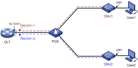
Network requirements
As shown in Figure 9, configure fiber backup for the two OLT ports to back up each other.
Configuration procedure
# Create fiber backup group 1.
<OLT> system-view
[OLT] ftth
[OLT-ftth] fiber-backup group 1
# Assign OLT 3/0/1 and OLT 3/0/2 to the fiber backup group in sequence. OLT 3/0/1 is the master port, and OLT 3/0/2 is the subordinate port.
[OLT-fiber-group1] member olt3/0/1
[OLT-fiber-group1] member olt3/0/2
[OLT-fiber-group1] display epon fiber-backup group 1
Fiber backup group 1 information:
Member Role State
OLT3/0/1 Master Active
OLT3/0/2 Standby Ready
Verifying the configuration
# Perform a master/subordinate switchover, and verify that OLT 3/0/2 becomes the master port.
[OLT-fiber-group1] port switch-over
[OLT-fiber-group1] display epon fiber-backup group 1
Fiber backup group 1 information:
Member Role State
OLT3/0/2 Master Active
OLT3/0/1 Standby Ready
# Shut down OLT 3/0/2, and verify that OLT 3/0/1 becomes the master port.
[OLT-fiber-group1] quit
[OLT] interface olt3/0/2
[OLT-Olt3/0/2] shutdown
[OLT-Olt3/0/2] display epon fiber-backup group 1
Fiber backup group 1 information:
Member Role State
OLT3/0/1 Master Active
OLT3/0/2 Standby Other
Remotely managing ONUs
Restrictions and guidelines: ONU configuration
Support for ONU features depends on the ONU model.
This section introduces only ONU configuration tasks. For information about non-EPON features supported by ONU ports, see "ONU port features and restrictions."
EPON is supported only on the default MDC. For more information about MDCs, see Virtual Technologies Configuration Guide.
ONU ports do not support ARP detection and MFF. For more information about ARP detection and MFF, see Security Configuration Guide.
For more information about commands not supported by ONU ports, see "Commands unavailable in ONU port view."
ONU tasks at a glance
To remotely manage ONUs, perform the following tasks:
2. (Optional.) Enabling ONU user authentication
4. (Optional.) Enabling ONU binding control on OLT ports
5. (Optional.) Configuring basic ONU management features
? Setting the aging timer for dynamic MAC address entries for an ONU
? Configuring the management VLAN of an ONU
? Setting the link type of an ONU port and assigning the port to VLANs
? Enabling user network management features on an ONU
? Configuring the loop protection action
6. (Optional.) Configuring advanced ONU management features
? Setting the multicast mode of an ONU
? Configuring ONU bandwidth allocation and related parameters
? Setting the state of the transmit power supply for transceiver modules of ONU PON ports
? Enabling UNI count-based PON port activation for an ONU
? Enabling an ONU to send flush messages
? Enabling packet statistics for an ONU
? Enabling event reporting for an ONU
? Enabling downlink traffic encryption for an ONU
? Bringing up a VoIP interface on an ONU
7. (Optional.) Updating and managing ONUs
8. (Optional.) Configuring UNIs
? Configuring basic settings of UNIs
? Setting the MAC learning limit on a UNI
? Setting the VLAN operation mode for a UNI
? Enabling fast-leave processing for a UNI
? Configuring UNI port isolation
? Enabling unknown multicast packet transparent transmission for UNIs
? Configuring port mirroring on a UNI
? Enabling packet statistics for a UNI
? Testing the cable connected to a UNI
9. (Optional.) Configuring ONU serial interfaces
Creating ONU ports
|
Command |
Remarks |
|
|
1. Enter system view. |
system-view |
N/A |
|
2. Enter OLT port view. |
interface olt interface-number |
N/A |
|
3. Create ONU ports. |
using onu onu-number-list |
By default, no ONU ports exist. |
Enabling ONU user authentication
About ONU user authentication
After you specify an authentication domain for ONU users on an OLT port, all users that access through the OLT port are authenticated by using the specified authentication domain.
The authentication domain defines the authentication scheme for ONU users. For more information about authentication domains, see Security Configuration Guide.
Restrictions and guidelines
The ONU authentication feature takes effect only when the automatic ONU binding feature is enabled. After you configure this feature, you must enable automatic ONU binding feature for the slot where the OLT port resides. For more information, see "Enabling automatic ONU binding."
Procedure
|
Step |
Command |
Remarks |
|
1. Enter system view. |
system-view |
N/A |
|
2. Enter OLT port view. |
interface olt interface-number |
N/A |
|
3. Enable ONU authentication and specify the domain used for ONU users. |
onu authentication-domain domain-name |
By default, ONU authentication is disabled on an OLT port. |
Configuring ONU bindings
About ONU bindings
An OLT authenticates ONUs based on the MAC address, LOID, or LOID and LOID password, and denies illegal ONU access to the system. For an ONU to pass authentication and be registered, you must bind the ONU to an ONU port. After the ONU passes authentication, the bound ONU port comes up, and the ONU comes online.
You can bind ONUs to ONU ports by using the following methods:
· Manually binding ONUs to ONU ports one by one—If the EPON system contains a small number of ONUs, you can manually bind each ONU to an ONU port.
· Performing batch ONU binding—If an ONU is not bound to any ONU port, the ONU cannot be registered. Such an ONU is called a silent ONU. Batch ONU binding automatically binds existing silent ONUs to ONU ports at a time. The ONUs that join the system after batch ONU binding is performed will not be bound.
Batch ONU binding applies to a newly established EPON system that contains only legal ONUs. You can use the bind onu-id command to manually bind new ONUs after batch ONU binding is performed.
· Enabling automatic ONU binding—Automatic ONU binding automatically binds ONU ports to existing silent ONUs and ONUs that join the system after this feature is enabled.
Automatic ONU binding applies to an EPON system where ONUs attached to the OLT are completely trustworthy. To unbind an ONU, first use the undo onu bind auto command to disable automatic ONU binding.
Restrictions and guidelines for ONU bindings
An OLT port can register a maximum of 63 ONUs.
The ONU attributes (MAC address, LOID, and LOID password) you use for ONU binding are not restricted by the ONU authentication mode set by using the authentication-mode command.
An ONU goes offline when you use the undo bind onu-id command to unbind it from its ONU port.
When you bind an ONU to an ONU port manually, follow these restrictions and guidelines:
· If fiber backup is not configured, you can create only one-to-one bindings between ONUs and ONU ports.
· For a fiber backup group, you can bind an ONU to two ONU ports that are on different member OLT ports.
Binding an ONU to an ONU port
|
Step |
Command |
Remarks |
|
1. Enter system view. |
system-view |
N/A |
|
2. Enter ONU port view. |
interface onu interface-number |
N/A |
|
3. Bind an ONU to the ONU port. |
bind onu-id { mac-address | loid loid | loid-password loid { cipher | simple } password } |
By default, no ONU is bound to an ONU port. |
Performing batch ONU binding
|
Step |
Command |
Remarks |
|
1. Enter system view. |
system-view |
N/A |
|
2. Enter FTTH view. |
ftth |
N/A |
|
3. Perform batch ONU binding. |
In standalone mode: In IRF mode: |
By default, batch ONU binding is not performed. |
Enabling automatic ONU binding
|
Step |
Command |
Remarks |
|
1. Enter system view. |
system-view |
N/A |
|
2. Enter FTTH view. |
ftth |
N/A |
|
3. Enable automatic ONU binding. |
In standalone mode: In IRF mode: |
By default, automatic ONU binding is disabled. |
Enabling ONU binding control on OLT ports
About ONU binding control on OLT ports
This feature allows an ONU to be bound to only one ONU port of an OLT port. With this feature enabled on an OLT port, if an ONU has registered with the OLT port, the ONU cannot register with any other OLT port.
Retractions and guidelines
Enabling this feature does not affect ONUs registered with different OLT ports.
For a fiber backup group to operate properly, do not assign an OLT port with this feature enabled to a fiber backup group. The fiber backup feature requires an ONU to be simultaneously bound to two ONU ports on two OLT ports that back up each other.
When you roll back the configuration by using a configuration file with the onu bind one-to-one command and ONU ports on different OLT ports are bound to the same ONU by using the bind onu-id command, the bind onu-id command configuration is kept for only an ONU port on one OLT port after configuration rollback.
Configured in OLT port view, this feature takes effect only on the OLT port. Configured in FTTH view, this feature takes effect on all OLT ports. You cannot configure this feature in both OLT port view and FTTH view.
Procedure
|
Step |
Command |
Remarks |
|
1. Enter system view |
system-view |
N/A |
|
2. Enter FTTH view or OLT port view. |
· Enter FTTH view: · Enter OLT port view: |
N/A |
|
3. Enable ONU binding control on OLT ports. |
onu bind one-to-one |
By default, ONU binding control is disabled for OLT ports. |
Setting the aging timer for dynamic MAC address entries for an ONU
About the aging timer of dynamic MAC address entries
For security and efficient use of table space, the MAC address table uses an aging timer for each dynamic MAC address entry. If a dynamic MAC address entry is not updated before the aging timer expires, the device deletes the entry. This aging mechanism ensures that the MAC address table can promptly update to accommodate latest network topology changes.
Procedure
|
Step |
Command |
Remarks |
|
1. Enter system view. |
system-view |
N/A |
|
2. Enter ONU port view. |
interface onu interface-number |
N/A |
|
3. Set the aging timer for dynamic MAC address entries. |
onu mac-address timer { aging seconds | no-aging } |
The default aging timer for dynamic MAC address entries is 300 seconds. |
Configuring the management VLAN of an ONU
About ONU management VLANs
To manage an ONU through Telnet, you must assign an IP address to the management VLAN interface of the ONU. This task allows you to specify the management VLAN of an ONU.
The management VLAN interface of an ONU can obtain an IP address by using the following methods:
· Manual IP address configuration.
· DHCP (with the ONU as a DHCP client).
A new IP address overwrites the old IP address if both methods are used.
Procedure
|
Step |
Command |
Remarks |
|
1. Enter system view. |
system-view |
N/A |
|
2. Enter ONU port view. |
interface onu interface-number |
N/A |
|
3. Configure the management VLAN of the ONU. |
management-vlan vlan-id |
By default, the management VLAN of an ONU is VLAN 1. If the management VLAN is changed, the IP address of the original management VLAN interface is deleted. |
|
4. Bring up the management VLAN interface. |
undo shutdown management-vlan-interface |
By default, a management VLAN interface is down. |
|
5. Assign an IP address to the management VLAN interface. |
· Manual configuration: · Automatic allocation: |
By default, the management VLAN interface of an H3C ONU uses the IP address 192.168.0.240 and subnet mask 255.255.255.0. |
Setting the link type of an ONU port and assigning the port to VLANs
About VLAN configuration of ONU ports
Configure an ONU port as an access port or trunk port by using the following guidelines:
· If a PC is directly connected to the ONU, configure the ONU port as an access port. The ONU port will receive and transmit only untagged packets.
· If a home gateway or Layer 2 switch is connected to the ONU, configure the ONU port as a trunk port.
Table 1 shows how access and trunk ONU ports process traffic.
Table 1 ONU port link types and packet processing
|
Port link type |
Traffic direction |
Packet processing |
|
Access |
Uplink |
Permits only untagged packets and tags these packets with the PVID. |
|
Downlink |
Permits only PVID-tagged packets and untags these packets. |
|
|
Trunk |
Uplink |
· Tags untagged packets with the PVID. · Forwards tagged packets with their tags intact. |
|
Downlink |
Permits only tagged packets of the VLANs that the port belongs to. |
Table 1 does not describe how packets are processed by an access port in VLAN 1 (the default VLAN setting of an ONU port). An ONU port using the default VLAN setting processes packets as follows:
· Permits untagged uplink packets, and tags these packets with VLAN ID 1.
· Permits downlink packets tagged with VLAN ID 1, and processes the tag based on the link types of the other ONU ports on the same OLT port.
? Removes the VLAN tag if the other ONU ports are access ports.
? Keeps the VLAN tag if the other ONU ports are trunk ports.
Configuring an ONU port as an access port and assigning the port to a VLAN
|
Step |
Command |
Remarks |
|
1. Enter system view. |
system-view |
N/A |
|
2. Enter ONU port view. |
interface onu interface-number |
N/A |
|
3. Set the link type to access. |
port link-type access |
By default, the link type of an ONU port is access. |
|
4. Assign the ONU port to a VLAN. |
port access vlan vlan-id |
By default, all ONU ports belong to VLAN 1. |
Configuring an ONU port as a trunk port and assigning the port to VLANs
|
Step |
Command |
Remarks |
|
1. Enter system view. |
system-view |
N/A |
|
2. Enter ONU port view. |
interface onu interface-number |
N/A |
|
3. Set the link type to trunk. |
port link-type trunk |
By default, the link type of an ONU port is access. |
|
4. Assign the port to all VLANs. |
port trunk permit vlan all |
By default, a trunk port permits only VLAN 1. You must assign the trunk port to all VLANs. Do not use the undo port trunk permit vlan command. |
|
5. Set the PVID of the port. |
port trunk pvid vlan vlan-id |
By default, the PVID of a trunk port is VLAN 1. |
Enabling user network management features on an ONU
About user network management features of an ONU
You can use an OLT to remotely enable RSTP, DHCP snooping, DHCP snooping Option 82, and PPPoE+ on an ONU through extended OAM packets.
· RSTP—RSTP enables an ONU to eliminate the loops in the user networks by blocking redundant links. For more information about RSTP, see Layer 2—LAN Switching Configuration Guide.
· Loop detection—Loop detection enables an ONU to detect loops in the user networks. If a loop is detected, loop detection takes the loop protection action on the looped port. For more information about loop detection, see Layer 2—LAN Switching Configuration Guide.
· DHCP snooping—DHCP snooping enables an ONU to generate a DHCP snooping table. The table records the IP address that each connected DHCP client obtains from the DHCP server and client MAC address information. For more information about DHCP snooping, see Layer 3—IP Services Configuration Guide.
· DHCP snooping Option 82—DHCP snooping Option 82 allows a DHCP server to record the location of DHCP clients. If DHCP snooping Option 82 is enabled on an ONU, the ONU adds the Option 82 field to the DHCP requests sent by DHCP clients before broadcasting the requests. The Option 82 field contains the ONU MAC address, the number of the UNI connected to the DHCP client, and the VLAN to which the UNI belongs.
· PPPoE+—PPPoE+, also called PPPoE Intermediate Agent, implements user port identification by adding user port information into PPPoE packets.
After you enable PPPoE+ on an ONU, the ONU processes the request packet sent by a PPPoE client as follows:
? If the request packet does not carry a PPPoE tag, the ONU adds the tag (which contains the UNI information) to the packet and forwards it to the OLT.
? If the request packet carries a PPPoE tag, the ONU directly forwards the packet to the OLT.
Restrictions and guidelines
As a best practice, do not enable both RSTP and loop detection on an ONU. These features might operate incorrectly when used together.
If the spanning tree feature is enabled globally on the OLT, you must enable RSTP on all ONUs. To avoid forwarding failures in the EPON system, make sure the ONUs are not selected as root bridges.
Procedure
|
Step |
Command |
Remarks |
|
1. Enter system view. |
system-view |
N/A |
|
2. Enter ONU port view. |
interface onu interface-number |
N/A |
|
3. Enable a user network management feature. |
onu protocol { dhcp-snooping | dhcp-snooping information | loopback-detection | pppoe | stp } enable |
By default, loop detection is enabled, and DHCP snooping, DHCP snooping Option 82, PPPoE+, and RSTP are disabled on an ONU. |
Configuring the loop protection action
About the loop protection action
The loop protection action determines how an ONU deals with a looped port. Loop protection actions include the following:
· No-learning—Disables MAC address learning.
· Semi-block—Disables MAC address learning and blocks inbound traffic.
· Shutdown—Shuts down the port.
Procedure
|
Step |
Command |
Remarks |
|
1. Enter system view. |
system-view |
N/A |
|
2. Enter ONU port view. |
interface onu interface-number |
N/A |
|
3. Set the loop protection action. |
onu protocol loopback-detection action { no-learning | semi-block | shutdown } |
By default, the loop protection action of an ONU port is semi-block. |
Setting the multicast mode of an ONU
Prerequisites for setting the multicast mode of an ONU
Before you configure the multicast mode of an ONU, first map its multicast IP addresses to a multicast VLAN.
When receiving an IGMP report message, the OLT verifies whether the multicast IP address in the message belongs to the multicast VLAN.
· If the address belongs to the multicast VLAN, the OLT generates a multicast forwarding entry for the multicast VLAN.
· If the address does not belong to the multicast VLAN, the OLT drops the message.
The IGMP snooping querier might send IGMP general queries with the source IP address 0.0.0.0. The ONU PON port that receives such queries will not be maintained as a dynamic router port. This might prevent the associated dynamic IGMP snooping forwarding entry from being correctly created at the data link layer and eventually cause multicast traffic forwarding failures. To avoid this problem, you can configure a non-all-zero IP address as the source IP address of the IGMP queries on the IGMP snooping querier.
To complete prerequisites for multicast mode configuration:
|
Step |
Command |
Remarks |
|
1. Enter system view. |
system-view |
N/A |
|
2. Enter FTTH view. |
ftth |
N/A |
|
3. Map multicast IP addresses to a multicast VLAN. |
multicast vlan-id vlan-id ip ip-address-list |
By default, no multicast IP addresses are mapped to a multicast VLAN. A multicast IP address can be mapped to only one multicast VLAN. |
|
4. Return to system view. |
quit |
N/A |
|
5. Enable IGMP snooping globally. |
igmp-snooping |
By default, IGMP snooping is disabled globally. |
|
6. Return to system view. |
quit |
N/A |
|
7. Enter the view of the multicast VLAN. |
vlan vlan-id |
N/A |
|
8. Enable IGMP snooping in the multicast VLAN. |
igmp-snooping enable |
By default, IGMP snooping is disabled in a VLAN. |
|
9. Enable IGMP snooping querier. |
igmp-snooping querier |
By default, IGMP snooping querier is disabled. If a network does not contain Layer 3 multicast devices, you must enable IGMP snooping querier on Layer 2 devices for them to generate and maintain multicast forwarding entries at the data link layer. |
|
10. Configure the source IP address for IGMP general queries. |
igmp-snooping general-query source-ip ip-address |
By default, the source IP address of IGMP general queries is the IP address of the current VLAN interface. If the current VLAN interface does not have an IP address, the source IP address is 0.0.0.0. |
|
11. Configure the source IP address for IGMP group-specific queries. |
igmp-snooping special-query source-ip ip-address |
By default, the source IP address of IGMP group-specific queries is one of the following: · The source address of IGMP group-specific queries if the IGMP snooping querier of the VLAN has received IGMP general queries. · The IP address of the current VLAN interface if the IGMP snooping querier does not receive an IGMP general query. · 0.0.0.0 if the IGMP snooping querier does not receive an IGMP general query and the current VLAN interface does not have an IP address. |
|
12. (Optional.) Enable dropping unknown multicast traffic. |
igmp-snooping drop-unknown |
N/A |
Configuring multicast in IGMP snooping mode
|
Step |
Command |
Remarks |
|
1. Enter system view. |
system-view |
N/A |
|
2. Enter ONU port view. |
interface onu interface-number |
N/A |
|
3. Set the multicast mode to IGMP snooping. |
multicast mode igmp-snooping |
By default, the multicast mode of an ONU is IGMP snooping. |
|
4. Assign a UNI to multicast VLANs. |
uni uni-number multicast vlan vlan-id-list |
By default, a UNI is not assigned to any multicast VLANs. |
|
5. Configure the number of multicast channels that users can access at the same time on a UNI. |
uni uni-number multicast-group-number number |
By default, the users on a UNI can access 64 multicast channels at the same time. |
|
6. Configure a UNI to remove the VLAN tag of downlink multicast flows. |
uni uni-number multicast-strip-tag enable |
By default, a UNI does not remove the VLAN tag of downlink multicast flows. |
|
7. Set IGMP snooping timers. |
onu protocol igmp-snooping timer { host-aging-time host-aging-time | max-response-time max-response-time | router-aging-time router-aging-time } |
This command is available on the ET704 ONU. The default values of IGMP snooping timers are as follows: · The multicast group member port aging timer is 260 seconds. · The query response timer is 1 second. · The router port aging timer is 105 seconds. |
|
8. Enable IGMP membership report suppression or IGMP leave suppression. |
onu protocol igmp-snooping suppression { leave | report } |
This command is available on the ET704 ONU. By default, IGMP leave suppression is enabled, and IGMP membership report suppression is disabled. |
Configuring multicast in multicast control mode
|
Step |
Command |
Remarks |
|
1. Enter system view. |
system-view |
N/A |
|
2. Enter ONU port view. |
interface onu interface-number |
N/A |
|
3. Set the multicast mode to multicast control. |
multicast mode multicast-control |
By default, the multicast mode of an ONU is IGMP snooping. |
|
4. Set the multicast group member port aging timer. |
multicast-control host-aging-time host-aging-time |
By default, the multicast group member port aging timer is 260 seconds. |
|
5. Configure the access to multicast channels on a UNI. |
uni uni-number multicast-control multicast-address multicast-address-list [ source-ip ip-address [ to ip-address ] ] rule { deny | permit [ channel-limit channel-number ] | preview time-slice preview-time [ preview-interval interval-time | preview-times preview-times [ reset-interval reset-interval-time ] ]* } |
By default, the access to multicast channels is not configured on a UNI. |
|
6. Configure a UNI to remove the VLAN tag of downlink multicast flows. |
uni uni-number multicast-strip-tag enable |
By default, a UNI does not remove the VLAN tag of downlink multicast flows. |
Configuring ONU bandwidth allocation and related parameters
About ONU bandwidth allocation
Perform this task to allocate uplink and downlink bandwidth based on different terminal service requirements to realize efficient bandwidth utilization.
Configuring downlink bandwidth allocation
|
Step |
Command |
Remarks |
|
1. Enter system view. |
system-view |
N/A |
|
2. Enter ONU port view. |
interface onu interface-number |
N/A |
|
3. Enable the downlink bandwidth allocation policy. |
bandwidth-downstream policy enable |
By default, the downlink bandwidth allocation policy is disabled on an ONU port. Downlink bandwidth limits take effect only when the downlink bandwidth allocation policy is enabled. |
|
4. Configure the downlink bandwidth limits. |
bandwidth-downstream { max-bandwidth bandwidth | max-burstsize burstsize } * |
By default, the maximum downlink bandwidth is 999994 Kbps (9999940 Kbps for 10G-EPON cards), and the maximum downlink burst buffer is 4194240 bytes. The downlink bandwidth limits take effect only on known unicast packets. |
Configuring uplink bandwidth allocation
|
Step |
Command |
Remarks |
|
1. Enter system view. |
system-view |
N/A |
|
2. Enter ONU port view. |
interface onu interface-number |
N/A |
|
3. Configure the uplink bandwidth limits. |
upstream-sla { fixed-bandwidth fixed-value | maximum-bandwidth max-value | minimum-bandwidth min-value | weight weight-value } * |
By default, the fixed uplink bandwidth is 0 kbps, the maximum uplink bandwidth is 23552 kbps, the minimum uplink bandwidth is 2048 kbps, and the bandwidth allocation weight is 1. The fixed uplink bandwidth cannot be greater than the minimum uplink bandwidth. On a 1G-EPON card, the sum of the minimum uplink bandwidth for all ONU ports of a single OLT port cannot exceed 950 Mbps. On a 10G-EPON card, the sum of the minimum uplink bandwidth for all ONU ports of a single OLT port cannot exceed 9500 Mbps. |
Configuring QoS for an ONU
Configuring congestion management for uplink ONU traffic
Restrictions and guidelines
In SP+WRR mode, as a best practice, use the SP queue scheduling for packets with priority values 6 and 7 (for example, network control protocol packets and TDM packets).
In SP mode, you must configure a minimum of one SP queue.
In WRR mode, you must configure a minimum of one WRR queue.
In SP+WRR mode, you must configure a minimum of one SP queue and one WRR queue.
On an ONU port, the sum of WRR queue weights must be 100.
Procedure
|
Step |
Command |
Remarks |
|
1. Enter system view. |
system-view |
N/A |
|
2. Enter ONU port view. |
interface onu interface-number |
N/A |
|
3. Configure the uplink traffic queue scheduling mode for the ONU. |
service-sla mode { sp | wrr | sp-wrr high-priority-boundary boundary-queue-id } [ cycle-length length ] |
By default, no uplink traffic queue scheduling mode is configured for an ONU. In SP+WRR mode, queues with IDs as boundary-queue-id and higher are configured as SP queues, and queues with IDs smaller than boundary-queue-id are configured as WRR queues. The cycle-length keyword specifies the DBA polling cycle and is only for administrator use. As a best practice, do not configure this keyword as a common user. |
|
4. Configure the uplink traffic queue parameters. |
service-sla queue queue-id { sp | wrr weight weight } [ [ fixed-packet-size fixed-packet-size ] fixed-bandwidth fixed-bandwidth ] guaranteed-bandwidth guaranteed-bandwidth best-effort-bandwidth best-effort-bandwidth |
By default, no uplink traffic queue parameters are configured for an ONU. |
|
5. Apply the uplink traffic queue scheduling configuration to the ONU. |
service-sla apply |
To modify the queue scheduling mode or queue parameters after executing this command, first execute the undo service-sla apply command. |
Configuring CoS-to-local priority mappings
|
Step |
Command |
Remarks |
|
1. Enter system view. |
system-view |
N/A |
|
2. Enter ONU port view. |
interface onu interface-number |
N/A |
|
3. Configure CoS-to-local priority mappings. |
qos cos-local-precedence-map cos0 cos1 cos2 cos3 cos4 cos5 cos6 cos7 |
Table 2 shows default CoS-to-local priority mappings. |
Table 2 Default CoS-to-local priority mappings
|
CoS priority |
Local precedence |
|
0 |
0 |
|
1 |
0 |
|
2 |
1 |
|
3 |
1 |
|
4 |
2 |
|
5 |
2 |
|
6 |
3 |
|
7 |
3 |
Configuring priority marking on a UNI
|
Step |
Command |
Remarks |
|
1. Enter system view. |
system-view |
N/A |
|
2. Enter ONU port view. |
interface onu interface-number |
N/A |
|
3. Configure priority marking on a UNI. |
uni uni-number classification-marking index index queue qid priority priority { selector operator matched-value } & <1-4> uni uni-number classification-marking index index queue qid priority priority { always-match | never-match } |
By default, priority marking is not configured on a UNI. Do not use the uni classification-marking commands together with the qos trust dscp command. For more information about the qos trust command, see ACL and QoS Command Reference. |
Configuring traffic policing on a UNI
|
Step |
Command |
Remarks |
|
1. Enter system view. |
system-view |
N/A |
|
2. Enter ONU port view. |
interface onu interface-number |
N/A |
|
3. Configure uplink traffic policing on a UNI. |
uni uni-number port-policy inbound { bucket-depth bucket-depth-value | cir cir-value | extra-burst-size extra-burst-size-value } * |
The bucket-depth bucket-depth-value option sets the CBS, and the extra-burst-size extra-burst-size-value option sets the EBS. By default, the CBS is 1522 bytes, the CIR is 0 kbps, and the EBS is 0 bytes. |
|
4. Configure downlink traffic policing on a UNI. |
uni uni-number port-policy outbound cir cir-value [ pir pir-value ] |
By default, the CIR is 0 kbps and the PIR is 0 kbps. |
Setting the state of the transmit power supply for transceiver modules of ONU PON ports
About the transmit power supply of ONU PON ports
In an EPON system, ONUs cannot transmit upstream traffic simultaneously. If an ONU fails and keeps sending optical signals, the other ONUs in the system cannot transmit upstream traffic because their transmission timeslots are occupied. To locate the faulty ONU, you can use the transceiver-txpower command to disable the transmit power supply of ONUs.
Procedure
|
Step |
Command |
Remarks |
|
1. Enter system view. |
system-view |
N/A |
|
2. Enter OLT port view. |
interface olt interface-number |
N/A |
|
3. Set the state of the transmit power supply for transceiver modules of ONU PON ports. |
transceiver-txpower { on | off | off seconds } pon { all | main | standby } onu { all | onu-number-list } |
By default, the transmit power supply is turned on for transceiver modules of all PON ports on an ONU. |
Enabling FEC for an ONU
About FEC
Forward Error Correction (FEC) can implement downlink error correction on the OLT and uplink error correction on the ONU. This feature reduces the bit error rate and extends the optical transmission distance. Because error correction codes are added to packets, the actual uplink bandwidth of an ONU cannot reach the configured uplink bandwidth.
Restrictions and guidelines
When 10G/10G-EPON ONUs connected to ONU ports on 10G-EPON cards come online, these ONUs support FEC by default and do not need this configuration. The undo forward-error-correction enable command does not take effect on these ONU ports.
Procedure
|
Step |
Command |
Remarks |
|
1. Enter system view. |
system-view |
N/A |
|
2. Enter ONU port view. |
interface onu interface-number |
N/A |
|
3. Enable FEC. |
forward-error-correction enable |
By default, FEC is disabled on an ONU port. |
Enabling UNI count-based PON port activation for an ONU
About UNI count-based PON port activation
After this feature is enabled, the ONU activates the PON port that has more online UNIs if two PON ports are online.
Restrictions and guidelines
This feature is supported by ET824-E ONUs.
Procedure
|
Step |
Command |
Remarks |
|
1. Enter system view. |
system-view |
N/A |
|
2. Enter ONU port view. |
interface onu interface-number |
N/A |
|
3. Enable UNI count-based PON port activation for the ONU. |
onu protocol smart-link uni-bind enable |
By default, UNI count-based PON port activation is disabled for an ONU. |
Enabling an ONU to send flush messages
|
Step |
Command |
|
1. Enter system view. |
system-view |
|
2. Enter ONU port view. |
interface onu interface-number |
|
3. Enable the ONU to send flush messages. |
onu protocol smart-link flush enable [ control-vlan vlan-id ] |
Enabling ONU alarms
About ONU alarms
The device supports remote configuration of ONU device alarms, PON port alarms, and UNI alarms.
Restrictions and guidelines
You can specify only one CTC protocol version on an ONU port.
Figure 10 shows the relationships between the triggering threshold trigger-value and clearing threshold clear-value of an alarm.
· For a lower limit alarm, for example, temp-low-alarm, the clearing threshold must be higher than or equal to the triggering threshold. For an upper limit alarm, for example, temp-high-alarm, the triggering threshold must be higher than or equal to the clearing threshold.
· For a pair of upper limit alarm and lower limit alarm, for example, rx-power-high-alarm and rx-power-low-alarm, the following requirements must be met:
? The clearing threshold of the upper limit alarm must be higher than or equal to the triggering threshold of the lower limit alarm.
? The triggering threshold of the upper limit alarm must be higher than or equal to the clearing threshold of the lower limit alarm.
Figure 10 Relationships between the triggering thresholds and clearing thresholds
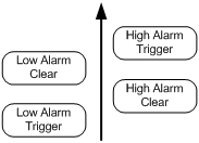
Procedure
|
Step |
Command |
Remarks |
|
1. Enter system view. |
system-view |
N/A |
|
2. Enter ONU port view. |
interface onu interface-number |
N/A |
|
3. Enable ONU alarms. |
alarm enable { onu onu-alarm | pon pon-alarm | uni uni-alarm } [ protocol { auto | ctc2.1 | ctc3.0 } ] [ threshold trigger-value clear-value ] |
By default, only the eth-port-loopback alarm is enabled for an ONU. If the protocol keyword is not specified, the autonegotiated CTC protocol is used. Whether the threshold keyword is required depends on the CTC alarms. For the support of the device for CTC alarms, see the alarm enable command in EPON Command Reference. |
Enabling packet statistics for an ONU
About ONU packet statistic collection
Perform this task to enable the packet statistics feature for an ONU.
Procedure
|
Step |
Command |
Remarks |
|
1. Enter system view. |
system-view |
N/A |
|
2. Enter ONU port view. |
interface onu interface-number |
N/A |
|
3. Enable packet statistics for the ONU. |
onu statistics enable [ period period-value ] |
By default, the packet statistics feature is enabled for an ONU, and the statistics collection interval is 4294967295 seconds. |
Enabling event reporting for an ONU
About event reporting
Perform this task for an ONU to inform the OLT of events such as configuration changes, failures, and debugging events.
Restrictions and guidelines
If an OLT manages a large number of ONUs, event report traffic from the ONUs might cause congestion. As a best practice, enable reporting only for critical events.
Procedure
|
Step |
Command |
Remarks |
|
1. Enter system view. |
system-view |
N/A |
|
2. Enter ONU port view. |
interface onu interface-number |
N/A |
|
3. Enable event reporting for the ONU. |
onu event { debug | log | trap } enable level severity |
By default, event reporting is disabled for an ONU. |
Enabling downlink traffic encryption for an ONU
About downlink traffic encryption
To protect user information against illegal access, enable encryption for the downlink traffic transmitted from the OLT to ONUs.
Procedure
|
Step |
Command |
Remarks |
|
1. Enter system view. |
system-view |
N/A |
|
2. Enter ONU port view. |
interface onu interface-number |
N/A |
|
3. Enable downlink traffic encryption for the ONU. |
encryption enable |
By default, downlink traffic encryption is enabled for an ONU. |
Bringing up a VoIP interface on an ONU
|
Step |
Command |
Remarks |
|
1. Enter system view. |
system-view |
N/A |
|
2. Enter ONU port view. |
interface onu interface-number |
N/A |
|
3. Bring up a VoIP interface. |
undo voip-port port-number shutdown |
By default, a VoIP interface is down. |
Updating and managing ONUs
You can update, deregister, or reboot an ONU from an OLT.
Updating ONUs
About ONU update
Table 3 shows the methods for updating ONUs. You can use one or multiple of the methods based on the network requirements.
Table 3 Remote ONU update methods
|
Method |
Description |
|
Update the ONUs of a specific type. You can perform this take multiple times to update different types of ONUs. This feature enables the OLT to automatically update ONUs that match the specified ONU type and do not have an update file. If a matching ONU is online, the ONU is updated. If a matching ONU is not online, the ONU is updated when it is online. |
|
|
Update the ONU bound to an ONU port. |
|
|
Update all ONUs attached to an OLT port. After you perform this task, whether the OLT updates a matching ONU that newly comes online depends on the creation time of the corresponding ONU port. · If the ONU port is created before you perform this task, the ONU will be updated. · If the ONU port is created after you perform this task, the ONU will not be updated. |
Prerequisites for ONU update
Before you perform an update, follow these restrictions and guidelines:
· You must upload the ONU update files to the active MPU of the OLT.
· To ensure successful update for ONUs that come online after an active/standby switchover, you must upload the update files to both the active and standby MPUs.
· Make sure the update files match the ONUs to be updated. If ONUs and update files do not match, the update for the ONUs will fail. For example, if you specify the update file for ET704-A ONUs in OLT port view, other types of ONUs attached to the OLT port cannot be updated.
· Update commands in interface view take precedence over the update commands in FTTH view. For example, the ONU bound to ONU 3/0/1:1 is the A type. If you specify the update file 1.app for ONUs of the A type in FTTH view and specify the update file 2.app in the view of ONU 3/0/1:1, the ONU uses 2.app for update. If you cancel the update configuration in the view of ONU 3/0/1:1, the OLT does not immediately update the ONU by using 1.app. The ONU will be updated after it is reregistered and its ONU port comes up.
Restrictions and guidelines
As a best practice, use the H3C protocol for H3C ONUs. To update ONUs from other vendors, use the CTC protocol. When the OLT operating mode of a 10G-EPON card is changed to 128-ONU, the ONUs connected to the EPON card do not support using the H3C protocol for upgrading ONUs.
During an update, follow these restrictions and guidelines:
· ONUs automatically reboot to update after they obtain update files from the OLT. To avoid update failures, do not power off the ONUs during an update.
· The update commands are automatically saved to the configuration file of the OLT after execution. If you only want to update online ONUs, use the undo form of the update commands after the update is completed on online ONUs.
· If an ONU is not online or its ONU port is down during an update, the OLT updates the ONU after the ONU is registered and its ONU port comes up.
Batch updating ONUs by type
|
Command |
Remarks |
|
|
1. Enter system view. |
system-view |
N/A |
|
2. Enter FTTH view. |
ftth |
N/A |
|
3. Update the ONUs of the specified type. |
update onu type onu-type [ protocol-type { h3c | ctc } ] filename filename |
You can update a maximum of 64 types of ONUs at the same time. |
Updating a single ONU
|
Step |
Command |
|
1. Enter system view. |
system-view |
|
2. Enter ONU port view. |
interface onu interface-number |
|
3. Update the ONU. |
update onu [ protocol-type { h3c | ctc } ] filename filename |
Batch updating ONUs by OLT port
|
update onu [ protocol-type { h3c | ctc } ] filename filename |
Deregistering an ONU
About ONU deregistration
After you deregister an ONU, the ONU will be re-registered.
Procedure
|
Step |
Command |
|
1. Enter system view. |
system-view |
|
2. Enter ONU port view. |
interface onu interface-number |
|
3. Deregister the ONU. |
deregister onu |
Rebooting an ONU
|
Step |
Command |
|
1. Enter system view. |
system-view |
|
2. Enter ONU port view. |
interface onu interface-number |
|
3. Reboot the ONU. |
reboot onu |
Configuring UNIs
Configuring basic settings of UNIs
About basic UNI settings
Basic settings of a UNI include the following:
· Duplex mode—When a UNI is operating in full duplex mode, it can send and receive packets simultaneously. When a UNI is operating in half duplex mode, it can either send or receive packets at a given time. When a UNI is operating in autonegotiation mode, the UNI and its peer port determine the duplex mode of the UNI through negotiation.
· Autonegotiation—The UNI and its peer port determine the duplex mode, cable type, and port rate of the UNI through negotiation.
· Flow control—If flow control is enabled for a UNI and its peer, the UNI will send messages to notify the peer to stop sending packets temporarily when congestion occurs on the UNI. This mechanism avoids packet loss.
· MDIX mode—You can use both crossover and straight-through Ethernet cables to connect UNIs to user terminals. To accommodate these types of cables, set the MDIX mode of a UNI by following these guidelines:
? As a best practice, set the MDIX mode to AutoMDIX. Set the MDIX mode to MDI or MDIX only when the device cannot determine the cable type.
? When a straight-through cable is used, configure the UNI to operate in an MDIX mode different than its peer.
? When a crossover cable is used, perform one of the following tasks:
- Configure the UNI to operate in the same MDIX mode as its peer.
- Configure either end to operate in AutoMDIX mode.
· Port rate—The port rate of a UNI can be manually set or autonegotiated by the UNI and its peer port.
Restrictions and guidelines
On a UNI, do not enable autonegotiation and manually set the duplex mode, MDIX mode, or port rate at the same time.
Procedure
|
Step |
Command |
Remarks |
|
1. Enter system view. |
system-view |
N/A |
|
2. Enter ONU port view. |
interface onu interface-number |
N/A |
|
3. Enable autonegotiation on a UNI. |
uni uni-number auto-negotiation |
By default, autonegotiation is enabled on a UNI. |
|
4. Configure the description for a UNI. |
uni uni-number description text |
By default, a UNI does not have a description. |
|
5. Set the duplex mode of a UNI. |
uni uni-number duplex { auto | full | half } |
By default, a UNI is operating in full-duplex mode. |
|
6. Enable flow control for a UNI. |
uni uni-number flow-control |
By default, flow control is disabled for a UNI. |
|
7. Set the MDIX mode for a UNI. |
uni uni-number mdix-mode { automdix | mdi | mdix } |
By default, the MDIX mode of a UNI is automdix. ET254 ONUs do not support this command. |
|
8. Shut down a UNI. |
uni uni-number shutdown |
By default, a UNI is up. |
|
9. Set the rate of a UNI. |
uni uni-number speed { 10 | 100 | 1000 | auto } |
By default, the rate of a UNI is 100 Mbps. |
|
10. Force a UNI to restart autonegotiation. |
uni uni-number restart auto-negotiation |
This command can be used only when autonegotiation is enabled. |
Setting the MAC learning limit on a UNI
About UNI MAC learning limit
This feature limits the MAC address table size for an ONU. A large MAC address table will degrade forwarding performance. When the MAC learning limit is reached on a UNI, the UNI stops learning MAC addresses.
Procedure
|
Step |
Command |
Remarks |
|
1. Enter system view. |
system-view |
N/A |
|
2. Enter ONU port view. |
interface onu interface-number |
N/A |
|
3. Set the MAC learning limit on a UNI. |
uni uni-number mac-address max-mac-count count |
By default, the number of MAC addresses that a UNI can learn is not limited. |
Setting the VLAN operation mode for a UNI
About the VLAN operation mode
The VLAN operation mode of a UNI can be one of the following:
· Transparent mode—Applicable when the service provider provides and manages the user-end family gateway or switch. In this scenario, the VLAN tags generated by the family gateway or switch are trusted. In transparent mode, an ONU transparently forwards the received uplink Ethernet packets (whether the Ethernet packets are VLAN-tagged or not) to the OLT without changing them. Downlink Ethernet packets are also forwarded transparently.
· Tag mode—Applicable when the VLAN tags generated by the user-end family gateway or switch are not trusted. For packet processing in tag mode, see Table 4.
· Translation mode—In translation mode, an ONU translates the CVLAN tag into a unique SVLAN tag. Translation mode ensures correct traffic forwarding if two users in an EPON system use the same VLAN ID. For packet processing in translation mode, see Table 4.
· QinQ mode—In QinQ mode, an ONU adds an SVLAN tag to packets that have a CVLAN tag. Then, the service provider can centrally manage and control the VLANs of the packets.
You can enable transparent transmission for VLANs used for special purposes when the QinQ mode is used. For example, a VLAN dedicated to a corporation or a management VLAN. When receiving packets tagged with the VLAN ID, the ONU does not add the SVLAN tag to the packets before forwarding them to the service provider network.
How an ONU in QinQ mode processes packets depends on the ONU model.
· Trunk mode—In this mode, a UNI of an ONU can send traffic from multiple VLANs. The traffic from the PVID of the UNI is untagged, and traffic from the other VLANs is VLAN-tagged. Typically, this mode is used for connecting network transmission devices. For packet processing in trunk mode, see Table 4.
· N:1 aggregation mode—In this mode, the ONU translates multiple VLAN tags of the uplink traffic into a unique SVLAN tag, and translates the SVLAN tag of the downlink traffic back into the original VLAN tags. For packet processing in N:1 aggregation mode, see Table 4.
Table 4 Packet processing for VLAN operation modes
|
VLAN operation mode |
Traffic direction |
Tagging status of packets |
Packet processing |
|
Transparent mode |
Uplink |
Tagged |
The UNI forwards the packet without any tag processing. |
|
Untagged |
|||
|
Downlink |
Tagged |
||
|
Untagged |
|||
|
Tag mode |
Uplink |
Tagged |
The UNI drops the packet. |
|
Untagged |
The UNI tags the packet with the PVID and forwards it. |
||
|
Downlink |
Tagged |
The ONU forwards the packet to the outgoing UNI based on the VLAN tag and removes the VLAN tag before sending the packet. |
|
|
Untagged |
The UNI drops the packet. |
||
|
Translation mode |
Uplink |
Tagged |
· If the VLAN tag is the PVID of the UNI, the UNI drops the packet. · If the VLAN tag matches a VLAN translation entry for the UNI, the UNI replaces the VLAN tag and forwards the packet. If no matching entry is found, the UNI drops the packet. |
|
Untagged |
The UNI tags the packet with the PVID and forwards the packet. |
||
|
Downlink |
Tagged |
· If the VLAN tag is the PVID of the UNI, the UNI removes the VLAN tag and forwards the packet. · If the VLAN tag matches a VLAN translation entry for the UNI, the UNI replaces the VLAN tag and forwards the packet. If no matching entry is found, the UNI drops the packet. |
|
|
Untagged |
The UNI drops the packet. |
||
|
Trunk mode |
Uplink |
Tagged |
If the VLAN ID of the packet is permitted by the UNI, the UNI forwards the packet. If the VLAN ID of the packet is not permitted by the UNI, the UNI drops the packet. |
|
Untagged |
The UNI tags the packet with the PVID and forwards it. |
||
|
Downlink |
Tagged |
If the VLAN ID of the packet is the PVID, processing for the packet depends on the ONU model and the software version. If the VLAN ID of the packet is permitted by the UNI, the UNI forwards the packet. If the VLAN ID of the packet is not permitted by the UNI, the UNI drops the packet. |
|
|
Untagged |
The UNI drops the packet. |
||
|
N:1 aggregation mode |
Uplink |
Tagged |
If the VLAN ID of the packet matches a VLAN aggregation entry on the UNI, the UNI translates the VLAN ID into the target VLAN ID in the entry, and records the MAC address of the packet. Then, the UNI forwards the packet. If the VLAN ID of the packet does not match a VLAN aggregation entry on the UNI, the UNI drops the packet. |
|
Untagged |
The UNI tags the packet with the PVID and forwards it. |
||
|
Downlink |
Tagged |
If the VLAN ID of the packet is the PVID, the UNI removes the VLAN tag of the packet and then forwards the packets. If the VLAN ID of the packet matches a VLAN aggregation entry on the UNI, the UNI translates the VLAN ID into the original VLAN ID in the entry based on the MAC address of the packet. Then, the UNI forwards the packet. If the VLAN ID of the packet does not match a VLAN aggregation entry on the UNI, the UNI drops the packet. |
|
|
Untagged |
The UNI drops the packet. |
Restrictions and guidelines
If the link type of all ONU ports on an OLT port is access, you must set the transparent mode for UNIs of the ONUs. This setting ensures that the ONU ports and users receive only untagged packets.
Procedure
|
Step |
Command |
Remarks |
|
1. Enter system view. |
system-view |
N/A |
|
2. Enter ONU port view. |
interface onu interface-number |
N/A |
|
3. Set the VLAN operation mode for a UNI. |
· Transparent mode: · Tag mode: · Translation mode: · QinQ mode: ? Enable QinQ mode: ? (Optional.) Specify the SVLAN tag for packets with the specified CVLAN
tags: ? (Optional.) Enable transparent transmission for the specified CVLANs: · Trunk mode: · N:1 aggregation mode: |
By default, the VLAN operation mode of a UNI is transparent. |
Enabling fast-leave processing for a UNI
About fast-leave processing
This feature immediately removes a UNI from the outgoing port list of the forwarding table when the UNI receives an IGMP leave message for a multicast group. Then, when the ONU receives IGMP group-specific queries for that multicast group, the ONU does not forward them to that UNI.
If only one host is attached to a UNI, fast-leave processing helps improve bandwidth and resource usage. If multiple hosts in the same multicast group are attached to a UNI, when one host leaves the multicast group, the other hosts cannot receive multicast data.
Before you enable fast-leave processing, make sure the ONU is operating in IGMP snooping mode. This feature takes effect only for IGMPv2 or IGMPv3 clients.
Procedure
|
Step |
Command |
Remarks |
|
1. Enter system view. |
system-view |
N/A |
|
2. Enter ONU port view. |
interface onu interface-number |
N/A |
|
3. (Optional.) Set the multicast mode to IGMP snooping. |
multicast mode igmp-snooping |
By default, the multicast mode of an ONU is IGMP snooping. |
|
4. Enable fast-leave processing for UNIs. |
· Enable fast-leave processing for all UNIs: · Enable fast-leave processing for a UNI: |
You cannot use both commands. By default, fast-leave processing is disabled for a UNI. |
Configuring UNI port isolation
About UNI port isolation
UNI port isolation improves security and allows flexible networking schemes by isolating UNIs at Layer 2. UNIs in an isolation group cannot communicate with each other.
Restrictions and guidelines
An ONU supports only one isolation group. The number of UNIs in the isolation group is not limited.
Procedure
|
Step |
Command |
Remarks |
|
1. Enter system view. |
system-view |
N/A |
|
2. Enter ONU port view. |
interface onu interface-number |
N/A |
|
3. Configure UNI port isolation. |
· Assign all UNIs on the ONU to the
isolation group: · Assign a UNI to the isolation group: |
You cannot use both commands. By default, a UNI is not in the isolation group. |
Enabling unknown multicast packet transparent transmission for UNIs
About unknown multicast packet transparent transmission for UNIs
With this feature enabled, UNIs on an ONU process frames destined for the specified multicast MAC addresses as follows:
· If the destination MAC address is 0100-ffff-ffff (referred to as global transparent transmission MAC address), the UNI ports flood the multicast packets destined for the MAC addresses starting with 0x0100.
When this feature is configured, as a best practice, do not configure known multicast services.
· If the destination MAC address is a value except 0100-ffff-ffff (referred to as non-global transparent transmission MAC address), the UNI ports multicast the multicast packets destined for the MAC address.
This feature forwards only unknown multicast packets. As a best practice, make sure the MAC address does not overlap with that of a known multicast service.
Restrictions and guidelines
On an ONU interface, the global transparent transmission MAC address configuration is mutually exclusive with the non-global transparent transmission MAC address configuration.
The global transparent transmission MAC address can be configured only by using the onu protocol transparent-multicast dest-mac mac-address command and does not support the vlan keyword.
Non-global transparent transmission MAC address configuration is supported in multicast control mode.
ET254-G-A ONUs support only the global transparent transmission MAC address configuration.
Procedure
|
Step |
Command |
Remarks |
|
1. Enter system view. |
system-view |
N/A |
|
2. Enter ONU port view. |
interface onu interface-number |
N/A |
|
3. Enable unknown multicast packet transparent transmission for UNIs. |
· Enable unknown multicast packet
transparent transmission for all UNIs on the ONU: · Enable unknown multicast packet transparent transmission
for a UNI on the ONU: |
Use either command. The two commands are mutually exclusive. By default, unknown multicast packet transparent transmission is disabled on UNIs. The ONU might drop unknown multicast packets. If you do not specify the vlan keyword, VLAN 1 is used. |
Configuring PoE for UNIs
Restrictions and guidelines
You can configure PoE for UNIs by using the onu poe command series and the uni poe command series. On one UNI, the onu poe command series and the uni poe command series for configuring the same feature are mutually exclusive.
· To configure PoE with the same parameters on all UNIs of an ONU, use the onu poe command series.
· To configure PoE on only some UNIs of an ONU or configure PoE with different parameters on UNIs of an ONU, use the uni poe command series.
· To switch the current commands series to the other command series, use the undo forms of the current command series to cancel the configuration first.
When the sum of power supplied to all PDs connected to UNIs of an ONU exceeds the maximum power of the ONU, the ONU might disable PoE for some UNIs to avoid power overload. As a best practice, use the alarm enable onu power-alarm command to enable the ONU to report power alarms to the OLT. For more information about the alarm enable command, see EPON Command Reference.
Configuring PoE for all UNIs of an ONU
|
Step |
Command |
Remarks |
|
1. Enter system view. |
system-view |
N/A |
|
2. Enter ONU port view. |
interface onu interface-number |
N/A |
|
3. Enable PoE for all UNIs of the ONU. |
onu poe enable |
By default, PoE is enabled for all UNIs of an ONU. |
|
4. Configure a power transmission mode for all UNIs of the ONU. |
onu poe mode { signal | spare } |
By default, the power transmission mode is power over signal cables (signal) for UNIs. |
|
5. (Optional.) Enable nonstandard PD detection for all UNIs of the ONU. |
onu poe legacy enable |
By default, nonstandard PD detection is disabled for UNIs. |
|
6. (Optional.) Configure the maximum PoE power for each UNI of the ONU. |
onu poe max-power { class { class0 | class1 | class2 | class3 | class4 | default } | value max-power-value } |
By default, the maximum power of an UNI depends on the maximum power class of the PD attached to the UNI. |
Configuring PoE for an UNI of an ONU
|
Step |
Command |
Remarks |
|
1. Enter system view. |
system-view |
N/A |
|
2. Enter ONU port view. |
interface onu interface-number |
N/A |
|
3. Enable PoE on a single UNI. |
uni uni-number poe enable |
By default, PoE is disabled for a single UNI. The default of the onu poe enable command takes effect preferentially, and PoE is enabled for all UNIs of an ONU. |
|
4. Configure a power transmission mode for an UNI. |
uni uni-number poe mode { signal | spare } |
By default, the power transmission mode is power over signal cables (signal) for an UNI. |
|
5. (Optional.) Enable nonstandard PD detection for an UNI. |
uni uni-number poe legacy enable |
By default, nonstandard PD detection is disabled for an UNI. |
|
6. (Optional.) Configure the maximum power of an UNI. |
uni uni-number poe max-power { class { default | class0 | class1 | class2 | class3 | class4 } | value max-power-value } |
By default, the maximum power of an UNI depends on the maximum power class of the PD attached to the UNI. |
|
7. (Optional.) Configure the power supply priority for an UNI. |
uni uni-number poe priority { critical | high | low } |
By default, the PoE priority of an UNI is critical. |
Configuring port mirroring on a UNI
About port mirroring
Port mirroring copies the packets passing through a port to another port that connects to a data monitoring device for packet analysis. The monitored port is the mirroring source port. The port connected to the data monitoring device is the mirroring destination port.
Restrictions and guidelines
A UNI cannot be both a mirroring source port and destination port.
Procedure
|
Step |
Command |
Remarks |
|
1. Enter system view. |
system-view |
N/A |
|
2. Enter ONU port view. |
interface onu interface-number |
N/A |
|
3. Configure a UNI as a mirroring source port. |
uni uni-number mirroring-port { both | inbound | outbound } |
By default, a UNI is not a mirroring source port. |
|
4. Configure a UNI as a mirroring destination port. |
uni uni-number monitor-port |
By default, a UNI is not a mirroring destination port. |
Enabling packet statistics for a UNI
About UNI packet statistic collection
Perform this task to enable the packet statistics feature for a UNI of an ONU.
Procedure
|
Step |
Command |
Remarks |
|
1. Enter system view. |
system-view |
N/A |
|
2. Enter ONU port view. |
interface onu interface-number |
N/A |
|
3. Enable packet statistics for a UNI. |
uni uni-number statistics enable [ period period-value ] |
By default, the packet statistics feature is enabled for a UNI, and the statistics collection interval is 4294967295 seconds. |
Testing the cable connected to a UNI
About the UNI cable test
Perform this task to test the cable connected to a UNI and display the test result.
Procedure
|
Step |
Command |
|
1. Enter system view. |
system-view |
|
2. Enter ONU port view. |
interface onu interface-number |
|
3. Test the cable connected to a UNI. |
uni uni-number virtual-cable-test |
Configuring ONU serial interfaces
About ONU serial interface configuration
Perform this task to set serial interface parameters and establish sessions on serial interfaces of an ONU.
Procedure
|
Step |
Command |
Remarks |
|
1. Enter system view. |
system-view |
N/A |
|
2. Enter ONU port view. |
interface onu interface-number |
N/A |
|
3. Set the number of data bits for a serial interface. |
serial interface-number databit { 5 | 6 | 7 | 8 } |
By default, the number of data bits is 8 for an ONU serial interface. |
|
4. Set the parity type for a serial interface. |
serial interface-number parity { even | mark | none | odd | space } |
By default, the parity type of an ONU serial interface is none, which indicates that no parity is used. |
|
5. Set the baud rate for a serial interface. |
serial interface-number speed { 300 | 600 | 1200 | 2400 | 4800 | 9600 | 19200 | 38400 | 57600 | 115200 } |
By default, the baud rate of an ONU serial interface is 9600 bps. |
|
6. Set the number of stop bits for a serial interface. |
serial interface-number stopbit { 1 | 1.5 | 2 } |
By default, the number of stop bits is 1 for an ONU serial interface. |
|
7. Establish a session on a serial interface. |
· Establish a TCP session with the ONU as the
client: · Establish a TCP session with the ONU as
the server: · Establish a UDP session with the ONU as
both the server and client: |
By default, no session is established on an ONU serial interface. |
Display and maintenance commands for ONUs
|
Task |
Command |
View |
|
Display IP address assignment information for an ONU that acts as a DHCP client. |
display dhcp-client |
ONU port view |
|
Display multicast information for an ONU port in multicast control mode. |
display epon multicast |
ONU port view |
|
(In standalone mode.) Display ONU information. |
display onu [ silent [ mac | loid ] ] { interface interface-type interface-number | slot slot-number } |
Any view |
|
(In IRF mode.) Display ONU information. |
display onu [ silent [ mac | loid ] ] { interface interface-type interface-number | chassis chassis-number slot slot-number } |
Any view |
|
Display information about a legal ONU by specifying its LOID. |
display onu loid loid |
Any view |
|
Display information about a legal ONU by specifying its MAC address. |
display onu mac-address mac-address |
Any view |
|
Display information about protocols supported by an ONU. |
display onu protocol { dhcp-snooping information | igmp-snooping | loopback-detection | pppoe | smart-link | stp } |
ONU port view |
|
Display information about UNI count-based PON port activation for an ONU. |
display onu protocol smart-link uni-bind information |
ONU port view |
|
Display unknown multicast packet transparent transmission configuration. |
display onu protocol transparent-multicast |
ONU port view |
|
Display information about a serial interface on an ONU. |
display serial-information interface-number |
ONU port view |
|
Display information about a UNI on an ONU. |
display uni uni-number |
ONU port view |
|
Display detailed information about an ONU. |
display vendor-specific information |
ONU port view |
|
Clear packet statistics on a serial interface on an ONU. |
reset counters serial serial-port-id |
ONU port view |
|
Clear packet statistics on UNIs. |
reset counters uni [ uni-number ] |
ONU port view |
|
Display information of a UNI. |
display uni uni-number |
ONU port view |
|
Clear packet statistics on UNIs. |
reset counters uni [ uni-number ] |
ONU port view |
ONU configuration examples
ONU binding configuration example
Network requirements
As shown in Figure 11, bind ONU1 (000f-e200-0031) and ONU2 (000f-e200-3749) to ONU ports ONU 3/0/1:1 and ONU 3/0/1:2, respectively.
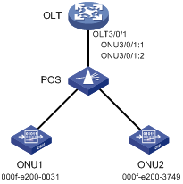
Configuration procedure
# Create ONU ports ONU 3/0/1:1 and ONU 3/0/1:2.
<OLT> system-view
[OLT] interface olt 3/0/1
[OLT-Olt3/0/1] using onu 1 to 2
[OLT-Olt3/0/1] quit
# Bind ONU1 to ONU 3/0/1:1.
[OLT] interface onu 3/0/1:1
[OLT-Onu3/0/1:1] bind onu-id 000f-e200-0031
[OLT-Onu3/0/1:1] quit
# Bind ONU2 to ONU 3/0/1:2.
[OLT] interface onu 3/0/1:2
[OLT-Onu3/0/1:2] bind onu-id 000f-e200-3749
[OLT-Onu3/0/1:2] quit
Verifying the configuration
# Power on ONU1 and ONU2, and verify that the ONUs have been bound to their respective ONU port.
<OLT> display onu interface olt 3/0/1
MAC LOID LLID Dist(M) Port Mode
l/Version Sft/Epm State Aging
000f-e200-0031 1 1 Onu1/0/1:1 302
105/100 Up N/A
000f-e200-3749 2 1 Onu1/0/1:2 320
105/100 Up N/A
--- 2 entries found ---
ONU user authentication configuration example
Network requirements
As shown in Figure 12, configure the OLT to use the RADIUS server to authenticate ONU users accessing the OLT as follows:
· The shared key for exchanging packets between the OLT and the RADIUS server is expert. The usernames sent to the RADIUS server do not carry domain names.
· When a user performs authentication, both the username and the password are the MAC address of the ONU (for example, 3C8C-40CF-0523).
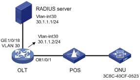
Configuration procedure
1. Configure ports and VLANs as shown in the network diagram. (Details not shown.)
2. Configure the OLT (RADIUS client):
# Create a RADIUS scheme named olt.
<OLT> system-view
[OLT] radius scheme olt
New RADIUS scheme.
# In RADIUS scheme olt, specify the primary authentication server with IP address 30.1.1.1 and plaintext shared key expert, and configure the device to remove the domain name from the usernames sent to the RADIUS servers.
[OLT-radius-olt] primary authentication 30.1.1.1 key simple expert
[OLT-radius-olt] user-name-format without-domain
[OLT-radius-olt] quit
# Create ISP domain 111, and configure the ISP domain to use RADIUS scheme olt for ONU user authentication.
[OLT] domain 111
[OLT-isp-111] authentication onu radius-scheme olt
[OLT-isp-111] quit
# Enable ONU authentication on OLT 1/0/1, and specify OLT 1/0/1 to use ISP domain 111 for ONU user authentication.
[OLT] interface Olt 1/0/1
[OLT-Olt1/0/1] onu authentication-domain 111
[OLT-Olt1/0/1] quit
# Enable automatic ONU binding on slot 1.
[OLT] ftth
[OLT-ftth] onu bind auto slot 1
[OLT-ftth] quit
|
|
NOTE: For information about the radius scheme, primary authentication, user-name-format, domain, and authentication onu commands, see AAA commands in Security Command Reference. |
3. Configure the RADIUS server:
# Add a local network access user named 3C8C-40CF-0523, and set the password to 3C8C-40CF-0523 in plain text for the user.
<RADIUS> system-view
[RADIUS] local-user 3C8C-40CF-0523 class network
New local user added.
[RADIUS-luser-network-3C8C-40CF-0523] password simple 3C8C-40CF-0523
[RADIUS-luser-network-3C8C-40CF-0523] quit
# Configure the IP address of the RADIUS client as 30.1.1.2 and the shared key as expert in plaintext form.
[RADIUS] radius-server client ip 30.1.1.2 key simple expert
# Activate the RADIUS server configuration.
[RADIUS] radius-server activate
|
|
NOTE: For information about the local-user, password, authorization-attribute, radius-server client, and radius-server activate commands, see AAA commands in Security Command Reference. |
Verifying the configuration
# Display information about activated RADIUS clients and RADIUS users on the RADIUS server.
[RADIUS] display radius-server active-client
Total 1 RADIUS clients.
Client IP: 30.1.1.2
[RADIUS] display radius-server active-user
Total 1 RADIUS users matched.
Username: 3C8C-40CF-0523
Description: Not configured
Authorization attributes:
VLAN ID: Not configured
ACL number: Not configured
Validity period:
Expiration time: Not configured
# Display ONU information on OLT 1/0/1.
[OLT] display onu interface olt 1/0/1
MAC LOID LLID Dist(M) Port Mode
l/Version Sft/Epm State Aging
3C8C-40CF-0523 10 1200 Onu1/0/1:1 BT/BV
S/E Up N/A
--- 1 entry found ---
The output shows that:
· After the ONU passes AAA authentication, its MAC address 3C8C-40CF-0523 is bound to ONU 1/0/1:1.
· The ONU port is up.
Multicast in IGMP snooping mode configuration example
Network requirements
As shown in Figure 13, the ONU has been bound to ONU 3/0/1:1.
Configure multicast in IGMP snooping mode on the ONU for User 1 to access channels 225.1.2.1 through 225.1.2.255 and User 2 to access channels 225.1.3.1 through 225.1.3.255.
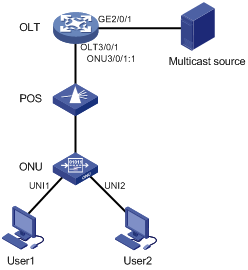
Configuration procedure
# Map the multicast IP addresses to multicast VLANs.
<OLT> system-view
[OLT] ftth
[OLT-ftth] multicast vlan-id 1002 ip 225.1.2.1 to 225.1.2.255
[OLT-ftth] multicast vlan-id 1003 ip 225.1.3.1 to 225.1.3.255
[OLT-ftth] quit
# Enable IGMP snooping globally.
[OLT] igmp-snooping
[OLT-igmp-snooping] quit
# Enable IGMP snooping and IGMP snooping querier and set the source IP addresses of IGMP general queries and group-specific queries to a valid IP address on the device in VLAN 1002 and VLAN 1003.
[OLT] vlan 1002
[OLT-vlan1002] igmp-snooping enable
[OLT-vlan1002] igmp-snooping querier
[OLT-vlan1002] igmp-snooping general-query source-ip 10.1.1.1
[OLT-vlan1002] igmp-snooping special-query source-ip 10.1.1.1
[OLT-vlan1002] quit
[OLT] vlan 1003
[OLT-vlan1003] igmp-snooping enable
[OLT-vlan1003] igmp-snooping querier
[OLT-vlan1003] igmp-snooping general-query source-ip 10.1.1.1
[OLT-vlan1003] igmp-snooping special-query source-ip 10.1.1.1
[OLT-vlan1003] quit
# Set the multicast mode to IGMP snooping on ONU 3/0/1:1.
[OLT] interface onu 3/0/1:1
[OLT-Onu3/0/1:1] multicast mode igmp-snooping
# Assign UNI 1 and UNI 2 of the ONU to multicast VLANs 1002 and 1003, respectively.
[OLT-Onu3/0/1:1] uni 1 multicast vlan 1002
[OLT-Onu3/0/1:1] uni 2 multicast vlan 1003
# Configure ONU 3/0/1:1 as a trunk port that permits all VLANs.
[OLT-Onu3/0/1:1] port link-type trunk
[OLT-Onu3/0/1:1] port trunk permit vlan all
# Configure UNI 1 and UNI 2 to remove the VLAN tag of downlink multicast flows.
[OLT-Onu3/0/1:1] uni 1 multicast-strip-tag enable
[OLT-Onu3/0/1:1] uni 2 multicast-strip-tag enable
[OLT-Onu3/0/1:1] quit
# Configure OLT 3/0/1 as a hybrid port, and assign it to VLAN 1002 and VLAN 1003 as a tagged member.
[OLT] interface olt 3/0/1
[OLT-Olt3/0/1] port link-type hybrid
[OLT-Olt3/0/1] port hybrid vlan 1002 1003 tagged
[OLT-Olt3/0/1] quit
# Configure GigabitEthernet 2/0/1 as a trunk port that permits VLAN 1002 and VLAN 1003.
[OLT] interface gigabitethernet2/0/1
[OLT-GigabitEthernet2/0/1] port link-type trunk
[OLT-GigabitEthernet2/0/1] port trunk permit vlan 1002 1003
[OLT-GigabitEthernet2/0/1] quit
Multicast in multicast control mode configuration example
Network requirements
As shown in Figure 14, the ONU has been bound to ONU 3/0/1:1.
Configure multicast in multicast control mode to provide different access rights for User 1 and User 2.
· User 1 has full access to Channel 1(225.1.1.1) and 60-second preview access to Channel 2 (225.1.2.1)
· User 2 only has access to Channel 2.
Configuration procedure
# Map the multicast IP addresses to multicast VLANs.
<OLT> system-view
[OLT] ftth
[OLT-ftth] multicast vlan-id 1002 ip 225.1.1.1
[OLT-ftth] multicast vlan-id 1003 ip 225.1.2.1
[OLT-ftth] quit
# Enable IGMP snooping globally.
[OLT] igmp-snooping
[OLT-igmp-snooping] quit
# Enable IGMP snooping in VLAN 1002 and VLAN 1003.
[OLT] vlan 1002
[OLT-vlan1002] igmp-snooping enable
[OLT-vlan1002] vlan 1003
[OLT-vlan1003] igmp-snooping enable
[OLT-vlan1003] quit
# Set the multicast mode to multicast control on ONU 3/0/1:1.
[OLT] interface onu 3/0/1:1
[OLT-Onu3/0/1:1] multicast mode multicast-control
# Configure UNI 1 to allow User 1 to access Channel 1 and to preview Channel 2 for only 60 seconds.
[OLT-Onu3/0/1:1] uni 1 multicast-control multicast-address 225.1.1.1 rule permit
[OLT-Onu3/0/1:1] uni 1 multicast-control multicast-address 225.1.2.1 rule preview time-slice 1
# Configure UNI 1 to remove the VLAN tags from downlink multicast packets.
[OLT-Onu3/0/1:1] uni 1 multicast-strip-tag enable
# Configure UNI 2 to allow User 2 to access Channel 2 only.
[OLT-Onu3/0/1:1] uni 2 multicast-control multicast-address 225.1.1.1 rule deny
[OLT-Onu3/0/1:1] uni 2 multicast-control multicast-address 225.1.2.1 rule permit
# Configure UNI 2 to remove the VLAN tags from downlink multicast packets.
[OLT-Onu3/0/1:1] uni 2 multicast-strip-tag enable
# Configure ONU 3/0/1:1 as a trunk port that permits all VLANs.
[OLT-Onu3/0/1:1] port link-type trunk
[OLT-Onu3/0/1:1] port trunk permit vlan all
[OLT-Onu3/0/1:1] quit
# Configure OLT 3/0/1 as a hybrid port, and assign it to VLAN 1002 and VLAN 1003 as a tagged member.
[OLT] interface olt 3/0/1
[OLT-Olt3/0/1] port link-type hybrid
[OLT-Olt3/0/1] port hybrid vlan 1002 1003 tagged
[OLT-Olt3/0/1] quit
# Configure GigabitEthernet 2/0/1 as a trunk port that permits VLAN 1002 and VLAN 1003.
[OLT] interface GigabitEthernet2/0/1
[OLT-GigabitEthernet2/0/1] port link-type trunk
[OLT-GigabitEthernet2/0/1] port trunk permit vlan 1002 1003
[OLT-GigabitEthernet2/0/1] quit
ONU update configuration example
Network requirements
As shown in Figure 15, update the type-A ONU bound to ONU 3/0/1:1 at Site A with the enhanced software version 110.
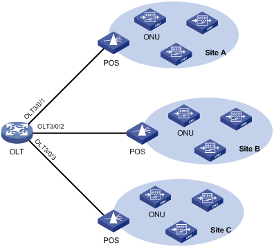
Configuration procedure
# Upload the file a110.app to the active and standby MPUs of the OLT. (Details not shown.)
# Update the type-A ONU bound to ONU 3/0/1:1 with the file a110.app.
<OLT> system-view
[OLT] interface onu 3/0/1:1
[OLT-Onu3/0/1:1] update onu filename a110.app
Update flash:/ a110.app?[Y/N]:y
Info: Download file to onu may take a long time, please wait...
Please wait while the firmware is being burnt, and check the software version after re-registration!
[OLT-Onu3/0/1:1] quit
Configuring BCMP proxy
Configuring an OLT as a BCMP proxy
About BCMP proxy
For a BCMP proxy to communicate with a BCMP server, you must specify the IP address of the server on the BCMP proxy.
Procedure
|
Step |
Command |
Remarks |
|
1. Enter system view. |
system-view |
N/A |
|
2. Enable the BCMP proxy feature. |
bcmp-proxy enable |
By default, the BCMP proxy feature is disabled. |
|
3. (Optional.) Specify the BCMP VLAN. |
bcmp-proxy vlan vlan-id |
By default, the BCMP VLAN is 4041. |
|
4. Specify the IP address of the BCMP server. |
bcmp-proxy server address ip-address |
By default, the IP address of the BCMP server is not specified. |
|
5. (Optional.) Specify the port number of the BCMP server. |
bcmp-proxy server port port-number |
By default, the port number of the BCMP server is 5000. |
Appendix: Support for non-EPON features and configuration restrictions
|
|
NOTE: Support for the non-EPON features depends on the ONU model and software version. |
OLT port features and restrictions
Table 5 shows the features supported by an OLT port.
|
Feature |
Tasks/commands and restrictions |
Related chapter/book |
|
Transceiver module management |
· Display transceiver alarms (display transceiver alarm). · Display the current values of the digital diagnosis parameters on transceiver modules (display transceiver diagnosis). · Display the key parameters of transceiver modules (display transceiver interface). · Display electronic label information for transceiver modules (display transceiver manuinfo). |
Fundamentals Command Reference |
|
Basic port parameters |
· Restore the default settings for an OLT port (default). · Configure a description for an OLT port (description). · Bring up or shut down an OLT port (shutdown). · Clear packet statistics on an OLT port (reset counters interface). · Enable broadcast storm suppression (broadcast-suppression). · Enable multicast storm suppression (multicast-suppression). · Enable unknown unicast storm suppression (unicast-suppression). When configuring broadcast/multicast/unknown unicast storm suppression on an OLT port of an 10G-EPON card, the pps keyword is not supported. |
Interface Command Reference |
|
Configure port isolation for OLT ports (port-isolate enable). |
Layer 2—LAN Switching Command Reference |
|
|
QinQ and VLAN mapping |
· Configure user-side QinQ or VLAN mapping. · Configure network-side VLAN mapping. |
"Configuring QinQ" "Configuring VLAN mapping" |
|
IGMP snooping |
Configure IPv4 multicast source port filtering (igmp-snooping source-deny). |
IP Multicast Command Reference |
|
MPLS L2VPN/VPLS/VXLAN |
Configure Ethernet service instances. Transparent transmission of 802.1X, IGMP, MLD, and BCMP protocol packets is not supported by VPLS. The Ethernet service instances on an OLT port support only the VLAN access mode. |
MPLS Configuration Guide VXLAN Configuration Guide |
|
QoS |
· Apply QoS policies on OLT ports (qos apply policy). · Display QoS policy information for OLT ports (display qos policy interface). · Configure priority mapping: ? Configure the DSCP priority for an OLT port (qos priority dscp priority-value). ? Configure the priority trust mode for an OLT port (qos trust). ? Display the priority trust mode and port priorities of an OLT port (display qos trust interface). · Set GTS parameters (qos gts). · Display the GTS information for OLT ports (display qos gts interface). · Configure rate limiting on an OLT port (qos lr). · Display the rate limit information for OLT ports (display qos lr). · Configure hardware congestion management: ? Enable SP queuing on an OLT port (qos sp). ? Display the SP queuing configuration of an OLT port (display qos queue sp interface). ? Enable WRR queuing on an OLT port (qos wrr). ? Display the WRR queuing configuration of an OLT port (display qos queue wrr interface). |
ACL and QoS Command Reference |
|
802.1X |
Configure 802.1X on an OLT port. When you configure 802.1X for EPON, as a best practice, execute the dot1x port-method macbased commando to configure MAC-based access control on an OLT port. If you configure this feature on an OLT port, you cannot configure this feature on the corresponding ONU ports. |
Security Configuration Guide |
|
MAC authentication |
· Enable MAC authentication (mac-authentication). · Display MAC authentication information for OLT ports (display mac-authentication). · Clear MAC authentication statistics (reset mac-authentication statistics). |
Security Command Reference |
|
Port security |
Configure port security on an OLT port. |
Security Configuration Guide |
|
IP source guard |
Configure IP source guard on OLT ports. |
Security Configuration Guide |
|
ARP attack protection |
· Enable the ARP packet rate limit feature (arp rate-limit) · Display ARP attack entries detected by source MAC-based ARP attack detection (display arp source-mac) · Configure an interface as an ARP trusted interface (arp detection trust). Only OLT ports on 10G-EPON cards support this feature. |
Security Command Reference |
|
ND attack defense |
· Display statistics for ND messages dropped by ND attack detection (display ipv6 nd detection statistics). · Configure an interface as an ND trusted interface (ipv6 nd detection trust). · Clear ND attack detection statistics (reset ipv6 nd detection statistics). Only OLT ports on 10G-EPON cards support this feature. |
Security Command Reference |
|
Smart Link |
Enable receiving of flush messages (smart-link flush enable). |
High Availability Command Reference |
|
Monitor Link |
Configure OLT ports as members of a monitor link group (port monitor-link group). |
High Availability Command Reference |
|
Port mirroring |
· Configure an OLT port as a source port for a mirroring group (mirroring-group mirroring-port). |
Network Management and Monitoring Command Reference |
|
SNMP notifications |
Enable link state notifications for OLT ports (enable snmp trap updown). |
Network Management and Monitoring Command Reference |
Commands unavailable in OLT port view
Table 6 Commands unavailable in OLT port view
|
Chapter |
Unavailable commands |
|
Interface Command Reference |
flow-control |
|
Layer 2—LAN Switching Command Reference |
· qinq ethernet-type · All loop detection commands |
|
IP Multicast Command Reference |
mld-snooping source-deny |
|
ACL and QoS Command Reference |
packet-filter |
|
ACL and QoS Command Reference |
qos priority |
|
Network Management and Monitoring Command Reference |
mirroring-group monitor-port |
ONU port features and restrictions
Table 7 ONU port features
|
Feature |
Tasks/commands and restrictions |
Related chapter/book |
|
Basic port parameters |
· Restore the default settings for an ONU port (default). · Configure a description for an ONU port (description). · Bring up or shut down an ONU port (shutdown). · Clear packet statistics on an ONU port (reset counters interface). · Enable broadcast suppression on an ONU port (broadcast-suppression). · Enable multicast storm suppression on an ONU port (multicast-suppression). · Enable unknown unicast storm suppression on an
ONU port (unicast-suppression). |
Interface Command Reference |
|
MAC address table |
· Display MAC address entries (display mac-address). · Display the global MAC address learning status and the MAC learning status of ONU ports (display mac-address mac-learning). · Add or modify a MAC address entry (mac-address). · Set the MAC learning limit on an OLT port (mac-address max-mac-count). |
Layer 2—LAN Switching Command Reference |
|
VLAN mapping |
Configure one-to-one VLAN mapping on ONU ports. |
Layer 2—LAN Switching Configuration Guide |
|
Loop detection |
Configure loop detection on ONU ports. When loop detection is enabled globally on a device, loop detection does not take effect on ONU ports. With the loopback-detection action { block | no-learning } command configured on an ONU port, the system disables MAC address learning on the ONU port when detecting loops on the ONU port. In this case, if you use the display loopback-detection command to display VLANs where loops are detected, the command output might display only part of the VLANs to which the ONU port belongs. |
Layer 2—LAN Switching Command Reference |
|
DHCP |
· Enable recording of client information in DHCP snooping entries (dhcp snooping binding record). · Enable MAC address check for DHCP snooping (dhcp snooping check mac-address). · Enable DHCP-REQUEST check for DHCP snooping (dhcp snooping check request-message). · Configure an ONU port as a DHCP packet blocking port (dhcp snooping deny). · Disable DHCP snooping on an ONU port (dhcp snooping disable). · Set the maximum number of DHCP snooping entries that an ONU port can learn (dhcp snooping max-learning-num). · Configure an ONU port as a trusted port (dhcp snooping trust). · Configure DHCP snooping to support Option 82: ? Enable DHCP snooping to support Option 82 (dhcp snooping information enable). ? Configure the padding mode and padding format for the Circuit ID sub-option (dhcp snooping information circuit-id). ? Configure the padding mode and padding format for the Remote ID sub-option (dhcp snooping information remote-id). ? Configure the handling strategy for Option 82 in request messages (dhcp snooping information strategy). ? Display Option 82 configuration on the DHCP snooping device (display dhcp snooping information). |
Layer 3—IP Services Command Reference |
|
IGMP snooping |
· Enable fast-leave processing on an ONU port (igmp-snooping fast-leave). · Set the maximum number of multicast groups that an ONU port can join (igmp-snooping group-limit). · Configure a multicast group policy on an ONU port to control the multicast groups that hosts attached to the port can join (igmp-snooping group-policy). · Configure an ONU port as a simulated member host for a multicast group (igmp-snooping host-join). · Enable multicast group replacement on an ONU port (igmp-snooping overflow-replace). · Configure a port as a static member port of a multicast group (igmp-snooping static-group). · Configure a port as a static router port (igmp-snooping static-router-port). |
IP Multicast Command Reference |
|
QoS |
· Apply QoS policies on ONU ports (qos apply policy). · Display QoS policy information for ONU ports (display qos policy interface). · Configure priority mapping: ? Configure the port priority for an ONU port (qos priority). ? Configure the priority trust mode for an ONU port (qos trust). ? Display the priority trust mode and port priorities of an ONU port (display qos trust interface). · Configure hardware congestion management: ? Enable SP queuing on an ONU port (qos sp). ? Display the SP queuing configuration of an ONU port (display qos queue sp interface). ? Configure WFQ queuing on an ONU port (qos wfq). ? Display the WFQ configuration of an ONU port (display qos queue wfq interface). |
ACL and QoS Command Reference |
|
802.1X |
Configure 802.1X authentication on ONU ports. ONU ports support only port-based access control. |
Security Configuration Guide |
|
Monitor Link |
Configure ONU ports as members of a monitor link group (port monitor-link group). |
High Availability Command Reference |
|
SNMP notifications |
Enable link state notifications for ONU ports (enable snmp trap updown). |
Network Management and Monitoring Command Reference |
Table 8 QoS configuration restrictions
|
Feature |
Restrictions |
|
ACL rule action |
When an ACL rule is used in a traffic class of a QoS policy, the action defined in the ACL rule (deny or permit) does not take effect. Instead, the traffic behavior associated with the traffic class determines the actions on the packets that match the ACL rule. |
|
Packet filtering |
· ONU ports only support packet filtering based on the following criteria: ? Source MAC address. ? Destination MAC address. ? Ethernet type. ? VLAN ID. ? Source IP address. ? Destination IP address. ? Source TCP port. ? Source UDP port. · Source MAC address-based packet filtering on an ONU port works only on the uplink direction and supports a maximum of 32 ACL rules. · Destination MAC address-based packet filtering on an ONU port works on both uplink and downlink directions at the same time and supports a maximum of 32 ACL rules. |
|
ACL rule limit |
· The number of ACL rules supported by Ethernet type-based packet filtering on an ONU port depends on the direction: ? Supports a maximum of 30 ACL rules if configured only in one direction. ? Supports a maximum of 16 ACL rules for each direction if configured in both directions. · The number of ACL rules supported by VLAN ID-based packet filtering on an ONU port depends on the direction: ? Supports a maximum of 6 ACL rules for the uplink direction. ? Supports a maximum 8 ACL rules for the downlink direction. · The number of ACL rules supported by source or destination IP address-based packet filtering on an ONU port depends on the direction: ? Supports a maximum of 24 ACL rules if configured only in one direction. ? Supports a maximum of 16 ACL rules for each direction if configured in both directions. · The number of ACL rules supported by source TCP/UDP port-based packet filtering on an ONU port depends on the direction: ? Supports a maximum of 24 ACL rules if configured only in one direction. ? Supports a maximum of 32 ACL rules if configured in both directions. |
Commands unavailable in ONU port view
Table 9 Commands unavailable in ONU port view
|
Chapter |
Unavailable commands |
|
Interface Command Reference |
· link-delay · loopback |
|
Layer 2—LAN Switching Command Reference |
· undo mac-address max-mac-count enable-forwarding · Many-to-one, one-to-two, and two-to-two VLAN mapping configuration commands · Two-to-one VLAN mapping configuration command (vlan mapping egress) · Zero-to-two VLAN mapping configuration command (vlan mapping untagged) |
|
Security Command Reference |
· arp rate-limit · dot1x unicast-trigger |
|
Layer 3—IP Services Command Reference |
dhcp snooping rate-limit |
|
IP Multicast Command Reference |
All MLD snooping commands |
|
Network Management and Monitoring Command Reference |
· mirroring-group mirroring-port · mirroring-group monitor-port |