- Table of Contents
-
- 12-Network Management and Monitoring Configuration Guide
- 00-Preface
- 01-System maintenance and debugging configuration
- 02-NQA configuration
- 03-NTP configuration
- 04-PoE configuration
- 05-SNMP configuration
- 06-RMON configuration
- 07-NETCONF configuration
- 08-EAA configuration
- 09-Process monitoring and maintenance configuration
- 10-Sampler configuration
- 11-Mirroring configuration
- 12-NetStream configuration
- 13-IPv6 NetStream configuration
- 14-sFlow configuration
- 15-Information center configuration
- 16-GOLD configuration
- 17-Packet capture configuration
- 18-VCF fabric configuration
- 19-CWMP configuration
- 20-SmartMC configuration
- 21-Ansible configuration
- Related Documents
-
| Title | Size | Download |
|---|---|---|
| 04-PoE configuration | 198.55 KB |
Configuration restrictions and guidelines
Enabling nonstandard PD detection
Configuring the maximum PoE power
Configuring the maximum PSE power
Configuring the maximum PI power
Configuring the PoE priority policy
Configuring the PSE priority policy
Configuring the PI priority policy
Configuring PSE power monitoring
Enabling PoE over-temperature protection
Configuring a PI by using a PoE profile
Upgrading PSE firmware in service
Displaying and maintaining PoE
Failure to set the priority of a PI to critical
Failure to apply a PoE profile to a PI
Configuring PoE
Overview
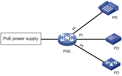
IEEE 802.3af-compliant power over Ethernet (PoE) enables a network device to supply power to terminals over twisted pair cables.
As shown in Figure 1, a PoE system includes the following elements:
· PoE power supply—A PoE power supply provides power for the entire PoE system.
· PSE—A power sourcing equipment (PSE) detects and classifies powered devices (PDs), supplies power to PDs, and monitors the PD power. PSEs include endpoint PSEs and midspan PSEs. An endpoint PSE is integrated in the device. A midspan PSE is independent of the device.
H3C PSEs are endpoint PSEs. Endpoint PSE devices are classified into single-PSE devices and multiple-PSE devices.
¡ A single-PSE device has only one PSE firmware.
¡ A multiple-PSE device has multiple PSEs. An interface card that can supply PoE power is a PSE. A multiple-PSE device uses PSE IDs to identify different PSEs. To display the mapping between the ID and slot number of a PSE, execute the display poe device command. The device is a multiple-PSE device.
· PI—A power interface (PI) is a PoE-capable Ethernet interface on a PSE.
· PD—A PD receives power from the PSE.
PDs include IP telephones, APs, portable chargers, POS terminals, and Web cameras.
You can also connect a PD to a redundant power source for reliability.
Configuration restrictions and guidelines
All models of the switch series, except for the S7506E (non-PoE) and S7506E-MF (non-PoE), support PoE. For a PoE-capable switch to supply PoE power, install an LSQ1GV48SD0, LSQ3GV48SC0, LSQM4GV48SA0, or LSQM4GV48SC0 interface module on the switch.
PoE configuration task list
You can configure a PI directly on the port or by configuring a PoE profile and applying the PoE profile to the PI. To configure one PI, configure it on the port. To configure multiple PIs in batches, use the PoE profile.
Before configuring PoE, make sure the PoE power supply and PSE are operating correctly. Otherwise, either you cannot configure PoE or the PoE configuration cannot take effect.
To configure PoE, perform the following tasks:
|
Tasks at a glance |
|
(Required.) Enabling PoE: |
|
(Optional.) Enabling nonstandard PD detection |
|
(Optional.) Configuring the PoE power: · Configuring the maximum PoE power |
|
(Optional.) Configuring the PoE priority policy: |
|
(Optional.) Configuring the PoE monitoring function: |
|
(Optional.) Configuring a PI by using a PoE profile: |
|
(Optional.) Upgrading PSE firmware in service |
Enabling PoE
Enabling PoE for a PSE
About enabling PoE for a PSE
The device that does not support dynamic power allocation has the following limitations:
· You cannot enable PoE for a PSE when the remaining PoE power is less than the PSE power, even if you are to use only a few PIs on the PSE.
· PSEs with higher power priority take precedence to receiver power over other PSEs. The device reserves power for PSEs with higher power priority even if no PDs are connected to them.
· When power overload occurs, the device cuts off power to PSEs with lower power priority (even if quite a few PDs are connected to them) to ensure power supply for PSEs with higher power priority.
The device that supports dynamic power allocation supplies power to PSEs as follows:
· PSEs configured with a maximum power
The device first ensures power supply for PSEs configured with a maximum power (these PSEs can grab power from PSEs not configured with a maximum power). These PSEs do not participate in dynamic power allocation. The device assigns power to them based on the PSE priority policy.
If the remaining power is not sufficient, you cannot enable PoE for a PSE configured with a maximum power.
· PSEs not configured with a maximum power
You can enable PoE for a PSE not configured with a maximum power regardless of whether the remaining power is sufficient.
The device dynamically allocates the remaining power to these PSEs.
¡ The power that the device allocates to a PSE equals the sum of its PD power consumptions. (The power allocated to a PSE will not exceed the PSE's maximum power. If the sum of the PD power consumptions exceeds the PSE's maximum power, the device allocates the maximum power to the PSE.)
¡ The device supplies power to a connected PD as long as the device has remaining power.
¡ If the device has remaining power after supplying power to all PDs on the PSEs, it reserves power for these PSEs for a newly connected PD.
Restrictions and guidelines
A PSE configured with a maximum power can grab power from PSEs participating in dynamic power distribution.
The PoE power will be reallocated upon the following events:
· Removal and reconnection of the PoE power supply.
· Change of the maximum PoE power.
· Increase or decrease of PSEs.
· Enabling or disabling PoE on a PSE.
· Change of a PSE's maximum power.
· Change of a PSE's power.
· Change of the PSE priority policy or PSE priorities.
· Change of the number of PDs on a PSE participating in dynamic power allocation.
· Master/subordinate device switchover or active/standby MPU switchover.
· Restoration of the device settings.
If the PoE power increases, the device dynamically allocates the increased power to unpowered PDs.
If the PoE power decreases and is not sufficient to support all PDs, the device performs the following tasks until the power is sufficient:
1. Cuts off PDs that participate in dynamic power allocation.
2. Cuts off PSEs configured with a maximum power based on the power cutoff priority.
Among the PSEs participating in dynamic power allocation, if PoE overload occurs because of power increase of PSEs that are receiving power, the device performs the following operations.
· If the PSE priority policy is enabled, the device cuts off power to the PSE with the lowest priority. For multiple PSEs with the same lower priority, the PSE with the largest ID will be cut off.
· If the PSE priority policy is not enabled, the PSE with the largest ID will be cut off.
· The PIs will be cut off based on the PI priority policy.
Procedure
To enable PoE for a PSE:
|
Step |
Command |
Remarks |
|
1. Enter system view. |
system-view |
N/A |
|
2. Enable PoE for a PSE. |
poe enable pse pse-id |
By default, a PSE is PoE-disabled. This configuration is supported only on the default MDC. To use this command to enable PoE for two PSEs, do not specify the second PSE until power is dynamically allocated to the first-specified PSE. |
Enabling PoE for a PI
About enabling PoE for a PI
After you enable PoE for a PI, the PI supplies power to the connected PD if the PI will not result in PSE power overload. PSE overload occurs when the sum of the power consumption of all PIs exceeds the maximum power of the PSE.
If the PI will result in PSE power overload, the following restrictions apply:
· If the PI priority policy is not enabled, the PI does not supply power to the connected PD.
· If the PI priority policy is enabled, whether the PDs can be powered depends on the priority of the PI.
For more information about the PI priority policy, see "Configuring the PI priority policy."
Power can be transmitted over a twisted pair cable in the following modes:
· Signal pair mode—Signal pairs (on pins 1, 2, 3, and 6) of the twisted pair cable are used for power transmission.
· Spare pair mode—Spare pairs (on pins 4, 5, 7, and 8) of the twisted pair cable are used for power transmission.
Restrictions and guidelines
A PI can supply power to a PD only when the PI and PD use the same power transmission mode. The PIs of the device support only the signal pair power transmission mode. It can supply power only to PDs that support signal pair power transmission mode.
Procedure
To enable PoE for a PI:
|
Step |
Command |
Remarks |
|
1. Enter system view. |
system-view |
N/A |
|
2. Enter PI view. |
interface interface-type interface-number |
N/A |
|
3. Enable PoE for the PI. |
poe enable |
By default, a PI is PoE-disabled. |
|
4. (Optional.) Configure power transmission mode. |
poe mode { signal | spare } |
By default, power is transmitted over the signal pairs of a twisted pair cable. The device does not support the spare pair power transmission mode. |
|
5. (Optional.) Configure a description for the PD connected to the PI. |
poe pd-description text |
By default, no description is available for the PD connected to the PI. |
Enabling nonstandard PD detection
|
Step |
Command |
Remarks |
|
1. Enter system view. |
system-view |
N/A |
|
2. Enable nonstandard PD detection. |
poe legacy enable pse pse-id |
By default, nonstandard PD detection is disabled. The PSE detects only IEEE 802.3af-compliant standard PDs and supplies power to them. This configuration is supported only on the default MDC. |
Configuring the PoE power
This section describes how to configure the maximum PoE power, the maximum PSE power, and the maximum PI power.
Configuring the maximum PoE power
The maximum PoE power is the maximum power that the device can provide to all PSEs.
The PoE power supply has a self-protection mechanism. When it is overloaded, the PoE power supply stops supplying power to all PSEs. To avoid this situation, you can configure a maximum PoE power smaller than the default maximum PoE power. After you configure the maximum PoE power, the system reallocates power based on the configured power. When PSEs require more power than the configured maximum power, the system does not supply power to new PSEs causing the power overload.
To configure the maximum PoE power:
|
Step |
Command |
Remarks |
|
1. Enter system view. |
system-view |
N/A |
|
2. Configure the maximum PoE power. |
· In standalone mode: · In IRF mode: |
By default, the maximum PoE power is the total maximum power of all operating power modules in the PoE power frame. This configuration is supported only on the default MDC. |
Configuring the maximum PSE power
The maximum power of a PSE is the maximum power that the PSE can provide to all its attached PDs.
Follow these guidelines when you configure the maximum PSE power:
· To avoid the PoE power overload situation, make sure the total power of all PSEs is less than the maximum PoE power.
· The maximum power of the PSE must be greater than or equal to the total maximum power of all its critical PIs to guarantee these PIs' power.
To configure the maximum PSE power:
|
Step |
Command |
Remarks |
|
1. Enter system view. |
system-view |
N/A |
|
2. Configure the maximum power for a PSE. |
poe pse pse-id max-power max-power |
By default, the maximum PSE power varies by PSE. You can perform the following operations to verify the default maximum power of a PSE: 1. Execute the undo poe pse pse-id max-power command. 2. Execute the display poe pse [ pse-id ] command. This configuration is supported only on the default MDC. |
Configuring the maximum PI power
The maximum PI power is the maximum power that a PI can provide to the connected PD. If the PD requires more power than the maximum PI power, the PI does not supply power to the PD.
To configure the maximum PI power:
|
Step |
Command |
Remarks |
|
1. Enter system view. |
system-view |
N/A |
|
2. Enter PI view. |
interface interface-type interface-number |
N/A |
|
3. Configure the maximum power for the PI. |
poe max-power max-power |
By default, the maximum power of a PI is 30000 milliwatts. |
Configuring the PoE priority policy
Configuring the PSE priority policy
About the PSE priority policy
The PSE priority policy performs priority-based power allocation in PoE power overload situations. The priority levels of a PSE are critical, high, and low in descending order. If the PoE power is sufficient, you do not need to enable the PSE priority policy.
(Device that has PSEs configured with a maximum power)
When PoE power overload occurs, the system supplies power to PSEs as follows:
· If you have not enabled the PSE priority policy, the system supplies power to PSEs depending on whether you have configured the maximum PoE power. For more information, see "_Ref381629437."
· If you have enabled the PSE priority policy, the system supplies power to PSEs as follows:
¡ If a PSE being powered causes PoE power overload, the system stops supplying power to the PSE.
¡ If a new PSE causes PoE power overload, the system supplies power to PSEs in priority descending order. If the new PSE has the same priority as a PSE being powered, the PSE being powered takes precedence. If multiple PSEs being powered have the same priority, the one with the smallest PSE ID takes precedence.
(Device that does not have PSEs configured with a maximum power)
If PSEs that participate in dynamic power allocation each have unpowered PDs because of PoE power insufficiency, you can enable the PSE priority policy for the device. The device supplies power to these PSEs based on the PSE priority policy when additional power is available. The PSE supplies power to the PIs based on the PI priority policy.
Restrictions and guidelines
Before you configure a PSE with critical priority, make sure the remaining power from the maximum PoE power minus maximum powers of PSEs with critical priority is greater than the maximum power of the PSE. This restriction does not apply to configuring PSEs with high and low priorities.
Configuration of PSEs whose power is preempted remains unchanged.
Procedure
To configure the PSE priority policy:
|
Step |
Command |
Remarks |
|
1. Enter system view. |
system-view |
N/A |
|
2. Enable the PSE priority policy. |
poe pse-policy priority |
By default, the PSE priority policy is disabled. This configuration is supported only on the default MDC. |
|
3. (Optional.) Configure a priority for a PSE. |
poe priority { critical | high | low } pse pse-id |
By default, the priority for a PSE is low. This configuration is supported only on the default MDC. |
Configuring the PI priority policy
About the PI priority policy
The PI priority policy enables the PSE to perform priority-based power allocation to PIs when PSE power overload occurs. The priority levels for PIs are critical, high, and low in descending order.
When PSE power overload occurs, the PSE supplies power to PDs as follows:
· If the PI priority policy is disabled, the PSE supplies power to PDs depending on whether you have configured the maximum PSE power.
¡ If you have configured the maximum PSE power, the PSE does not supply power to the newly-added or existing PD that causes PSE power overload.
¡ If you have not configured the maximum PSE power, the PoE self-protection mechanism is triggered. The PSE stops supplying power to all PDs.
· If the PI priority policy is enabled, the PSE supplies power to PDs as follows:
¡ If a PD being powered causes PSE power overload, the PSE stops supplying power to the PD.
¡ If a newly-added PD causes PSE power overload, the PSE supplies power to PDs in priority descending order of the PIs to which they are connected. If the newly-added PD and a PD being powered have the same priority, the PD being powered takes precedence. If multiple PIs being powered have the same priority, the PIs with smaller IDs takes precedence.
Restrictions and guidelines
Before you configure a PI with critical priority, make sure the remaining power from the maximum PSE power minus the maximum powers of the existing PIs with critical priority is greater than maximum power of the PI.
Configuration of a PI whose power is preempted remains unchanged.
Procedure
To configure the PI priority policy:
|
Step |
Command |
Remarks |
|
1. Enter system view. |
system-view |
N/A |
|
2. Enable the PI priority policy. |
poe pd-policy priority |
By default, the PI priority policy is disabled. |
|
3. Enter PI view. |
interface interface-type interface-number |
N/A |
|
4. (Optional.) Configure a priority for the PI. |
poe priority { critical | high | low } |
By default, the priority for a PI is low. |
Configuring PoE monitoring
When the PoE monitoring function is enabled, the system monitors PSEs, PDs, and device temperature in real time. If a specific value exceeds the threshold, the system automatically takes self-protection measures.
If a PSE starts or stops power supply to a PD, the system automatically sends a notification message. For more information, see "Configuring SNMP."
Configuring PSE power monitoring
The system monitors PSE power utilization and sends notification messages when PSE power utilization exceeds or drops below the threshold. If PSE power utilization crosses the threshold multiple times in succession, the system sends notification messages only for the first crossing. For more information about the notification message, see "Configuring SNMP."
To configure a PSE power alarm threshold:
|
Step |
Command |
Remarks |
|
1. Enter system view. |
system-view |
N/A |
|
2. Configure a power alarm threshold for the PSE. |
poe utilization-threshold utilization-threshold-value pse pse-id |
By default, the power alarm threshold for the PSE is 80%. This configuration is supported only on the default MDC. |
Enabling PoE over-temperature protection
The PoE over-temperature protection enables the system to monitor the chassis internal temperature in real time. When the temperature exceeds the upper limit or drops below the lower limit, the system disables PoE for all PIs. The upper and lower temperature limits depend on hardware specifications and are not configurable at the CLI.
To enable PoE over-temperature protection:
|
Step |
Command |
Remarks |
|
1. Enter system view. |
system-view |
N/A |
|
2. Enable PoE over-temperature protection. |
poe temperature-protection enable |
By default, PoE over-temperature protection is enabled. This configuration is supported only on the default MDC. |
Configuring a PI by using a PoE profile
A PoE profile is a set of PoE configurations. You can apply a PoE profile to one or multiple PIs. When a PD is moved to another PI, you only need to apply the PoE profile to the new PI.
You can configure a PI either on the port or by using a PoE profile. Follow these guidelines when you configure parameters for a PI:
· The poe max-power max-power and poe priority { critical | high | low } commands must be configured in the same method.
· If you configure a parameter twice with different methods, only the first configuration takes effect. To validate the second configuration, delete the first configuration.
Configuring a PoE profile
|
Step |
Command |
Remarks |
|
1. Enter system view. |
system-view |
N/A |
|
2. Create a PoE profile, and enter PoE profile view. |
poe-profile profile-name [ index ] |
N/A |
|
3. Enable PoE. |
poe enable |
By default, this function is disabled. |
|
4. (Optional.) Configure the maximum PI power. |
poe max-power max-power |
The default maximum PI power is 30000 milliwatts. |
|
5. (Optional.) Configure PoE power transmission mode. |
poe mode { signal | spare } |
The default mode is power over signal pins (signal). The device does not support the spare mode. |
|
6. (Optional.) Configure PI priority. |
poe priority { critical | high | low } |
The default priority is low. |
Applying a PoE profile
You can apply a PoE profile in system view or PI view. If you perform the operation in both views, the most recent operation takes effect. To apply a PoE profile to multiple PIs, perform the operation in system view. If a PoE profile is applied, it cannot be deleted or modified before you remove its application.
A PoE profile can be applied to multiple PIs, but a PI can have only one PoE profile.
Applying a PoE profile to multiple PIs in system view
|
Step |
Command |
|
1. Enter system view. |
system-view |
|
2. Apply a PoE profile to one or multiple PIs. |
apply poe-profile { index index | name profile-name } interface interface-range |
Applying a PoE profile to a PI in PI view
|
Step |
Command |
|
1. Enter system view. |
system-view |
|
2. Enter PI view. |
interface interface-type interface-number |
|
3. Apply the PoE profile to the interface. |
apply poe-profile { index index | name profile-name } |
Upgrading PSE firmware in service
You can upgrade the PSE firmware in service in either of the following modes:
· Refresh mode—Updates the PSE firmware without deleting it. You can use this mode if the firmware is available.
· Full mode—Deletes the current PSE firmware and reloads a new one. You can use this mode if the firmware is unavailable, and execution of all PoE commands fails.
If the PSE firmware upgrade fails because of interruption such as a device reboot, you can restart the device and upgrade it in full mode again. After the upgrade, the PSE will automatically restart and the PIs will be temporarily powered off. After the restart, the new PSE firmware will take effect and the PIs will be powered on again.
To upgrade the PSE firmware in service:
|
Step |
Command |
Remarks |
|
1. Enter system view. |
system-view |
N/A |
|
2. Upgrade the PSE firmware in service. |
This configuration is supported only on the default MDC. |
Displaying and maintaining PoE
Except for the display poe interface, display poe interface power, display poe-profile, and display poe-profile interface commands, all the other display commands are supported only on the default MDC.
Execute display commands in any view.
|
Task |
Command |
Remarks |
|
Display general PSE information (in standalone mode). |
display poe device [ slot slot-number ] |
This configuration is supported only on the default MDC. |
|
Display general PSE information (in IRF mode). |
display poe device [ chassis chassis-number slot slot-number ] |
This configuration is supported only on the default MDC. |
|
Display the power supplying information for the specified PI. |
display poe interface [ interface-type interface-number ] |
This configuration is supported only on the default MDC. |
|
Display power information for PIs. |
display poe interface power [ interface-type interface-number ] |
This configuration is supported only on the default MDC. |
|
Display PoE power usage information (in standalone mode). |
display poe power-usage |
This configuration is supported only on the default MDC. |
|
Display PoE power usage information (in IRF mode). |
display poe power-usage [ chassis chassis-number] |
This configuration is supported only on the default MDC. |
|
Display detailed PSE information. |
display poe pse [ pse-id ] |
This configuration is supported only on the default MDC. |
|
Display the power supplying information for all PIs on a PSE. |
display poe pse pse-id interface |
This configuration is supported only on the default MDC. |
|
Display power information for all PIs on a PSE. |
display poe pse pse-id interface power |
This configuration is supported only on the default MDC. |
|
Display information about the PoE power supply (in standalone mode). |
display poe-power |
This configuration is supported only on the default MDC. |
|
Display information about the PoE power supply (in IRF mode). |
display poe-power [ chassis chassis-number ] |
This configuration is supported only on the default MDC. |
|
Display PoE power information (in standalone mode). |
display poe-power |
This configuration is supported only on the default MDC. |
|
Display PoE power information (in IRF mode). |
display poe-power [ chassis chassis-number ] |
This configuration is supported only on the default MDC. |
|
Display all information about the PoE profile. |
display poe-profile [ index index | name profile-name ] |
N/A |
|
Display all information about the PoE profile applied to the specified PI. |
display poe-profile interface interface-type interface-number |
N/A |
PoE configuration example
Network requirements
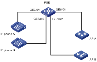
As shown in Figure 2, the device has PSE 10 and PSE 16 in slot 3 and slot 5, respectively. Configure PoE to meet the following requirements:
· PSE 10 has a maximum power of 400 watts.
· The device supplies PoE power to IP phones and APs.
· IP phone B takes precedence over other devices to receive power when a power overload occurs.
· The power supplied to AP B does not exceed 9000 milliwatts.
Configuration procedure
# Enable the PI priority policy.
<PSE> system-view
[PSE] poe pd-policy priority
# Enable PoE for the PSEs.
[PSE] poe enable pse 16
# Set the maximum power of PSE 10 to 400 watts.
[PSE] poe pse 10 max-power 400
# Enable PoE on GigabitEthernet 3/0/1 and GigabitEthernet 5/0/1.
[PSE] interface gigabitethernet 3/0/1
[PSE-GigabitEthernet3/0/1] poe enable
[PSE-GigabitEthernet3/0/1] quit
[PSE] interface gigabitethernet 5/0/1
[PSE-GigabitEthernet5/0/1] poe enable
[PSE-GigabitEthernet5/0/1] quit
# Enable PoE on GigabitEthernet 3/0/2, and set its power priority to critical.
[PSE] interface gigabitethernet 3/0/2
[PSE-GigabitEthernet3/0/2] poe enable
[PSE-GigabitEthernet3/0/2] poe priority critical
[PSE-GigabitEthernet3/0/2] quit
# Enable PoE on GigabitEthernet 5/0/2, and set its maximum power to 9000 milliwatts.
[PSE] interface gigabitethernet 5/0/2
[PSE-GigabitEthernet5/0/2] poe enable
[PSE-GigabitEthernet5/0/2] poe max-power 9000
Verifying the configuration
# Verify that the device is supplying power correctly to the IP phones and APs, and the IP phones and APs are operating correctly.
Troubleshooting PoE
Failure to set the priority of a PI to critical
Symptom
Power supply priority configuration for a PI failed.
Solution
To resolve the problem:
1. Increase the maximum PSE power or reduce the maximum power of the PI if the remaining guaranteed power of the PSE cannot be modified.
2. Remove the priority that is already configured.
3. If the problem persists, contact H3C Support.
Failure to apply a PoE profile to a PI
Symptom
PoE profile application for a PI failed.
Solution
To resolve the problem:
1. Remove the original configurations.
2. Modify the configurations in the PoE profile.
3. Remove the application of the undesired PoE profile from the PI.
4. If the problem persists, contact H3C Support.