- Table of Contents
-
- 07-IP Multicast Configuration Guide
- 00-Preface
- 01-Multicast Overview
- 02-IGMP snooping configuration
- 03-PIM snooping configuration
- 04-Multicast VLAN configuration
- 05-Multicast routing and forwarding configuration
- 06-IGMP configuration
- 07-PIM configuration
- 08-MSDP configuration
- 09-Multicast VPN configuration
- 10-MLD snooping configuration
- 11-IPv6 PIM snooping configuration
- 12-IPv6 multicast VLAN configuration
- 13-IPv6 multicast routing and forwarding configuration
- 14-MLD configuration
- 15-IPv6 PIM configuration
- Related Documents
-
| Title | Size | Download |
|---|---|---|
| 04-Multicast VLAN configuration | 163.58 KB |
Multicast VLAN configuration task list
Configuring a sub-VLAN-based multicast VLAN
Configuration restrictions and guidelines
Configuring a port-based multicast VLAN
Configuring user port attributes
Assigning user ports to a multicast VLAN
Setting the maximum number of multicast VLAN forwarding entries
Displaying and maintaining multicast VLANs
Multicast VLAN configuration examples
Sub-VLAN-based multicast VLAN configuration example
Port-based multicast VLAN configuration example
Configuring multicast VLANs
Overview
As shown in Figure 1, Host A, Host B, and Host C are in three different VLANs and the same multicast group. When Switch A (Layer 3 device) receives multicast data for that group, it sends three copies of the multicast data to Switch B (Layer 2 device). This occupies a large amount of bandwidth and increases the burden on the Layer 3 device.
Figure 1 Multicast transmission without the multicast VLAN feature
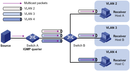
After a multicast VLAN is configured on Switch B, Switch A sends only one copy of the multicast data to the multicast VLAN on Switch B. This method saves network bandwidth and lessens the burden on the Layer 3 device.
Multicast VLANs include sub-VLAN-based multicast VLANs and port-based multicast VLANs.
Sub-VLAN-based multicast VLAN
As shown in Figure 2:
· Host A, Host B, and Host C are in VLAN 2 through VLAN 4, respectively.
· On Switch B, VLAN 10 is a multicast VLAN. VLAN 2 through VLAN 4 are sub-VLANs of VLAN 10.
· IGMP snooping is enabled for the multicast VLAN and its sub-VLANs.
Figure 2 Sub-VLAN-based multicast VLAN
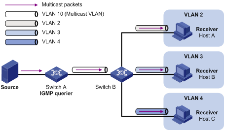
IGMP snooping manages router ports in the multicast VLAN and member ports in each sub-VLAN. When Switch A receives multicast data from the multicast source, it sends only one copy of the multicast data to the multicast VLAN on Switch B. Then, Switch B sends a separate copy to each sub-VLAN in the multicast VLAN.
Port-based multicast VLAN
As shown in Figure 3:
· Host A, Host B, and Host C are in VLAN 2 through VLAN 4, respectively.
· On Switch B, VLAN 10 is a multicast VLAN. All the user ports are hybrid ports and are assigned to VLAN 10.
· IGMP snooping is enabled for the multicast VLAN and VLAN 2 through VLAN 4.
Figure 3 Port-based multicast VLAN
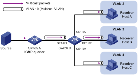
IGMP snooping manages the router ports and member ports in the multicast VLAN. When Switch A receives multicast data from the multicast source, it sends only one copy of the multicast data to the multicast VLAN on Switch B. Switch B sends a separate copy to each user port in the multicast VLAN.
Multicast VLAN configuration task list
|
Tasks at a glance |
|
(Required.) Perform one of the following tasks: · Configuring a sub-VLAN-based multicast VLAN · Configuring a port-based multicast VLAN: |
|
(Optional.) Setting the maximum number of multicast VLAN forwarding entries |
When you configure the multicast VLANs, follow these guidelines:
· If you have configured both a sub-VLAN-based multicast VLAN and a port-based multicast VLAN on a device, the port-based multicast VLAN configuration takes effect.
· Do not configure a multicast VLAN on a device that is enabled with IP multicast routing. Otherwise, the system displays errors.
· Do not enable IP multicast routing on a device that is configured with multicast VLANs. Otherwise, multicast forwarding exceptions occur.
· Do not configure a VLAN as a multicast VLAN or a multicast sub-VLAN if the VLAN interface is enabled with PIM or IGMP. Otherwise, the system displays errors.
· Do not enable PIM or IGMP on a VLAN interface if the VLAN interface belongs to a multicast VLAN or a multicast sub-VLAN. Otherwise, multicast forwarding exceptions occur.
· The multicast VLAN feature does not take effect on secondary VLANs. As a best practice, do not configure the multicast VLAN feature for secondary VLANs. For more information about secondary VLANs, see Layer 2—LAN Switching Configuration Guide.
Configuring a sub-VLAN-based multicast VLAN
To configure a sub-VLAN-based multicast VLAN, configure a VLAN as a multicast VLAN, and assign the VLANs that contain multicast receivers to the multicast VLAN as sub-VLANs.
Configuration prerequisites
Before you configure a sub-VLAN-based multicast VLAN, complete the following tasks:
· Create VLANs as required.
Configuration restrictions and guidelines
When you configure a sub-VLAN-based multicast VLAN, follow these restrictions and guidelines:
· The VLAN to be configured as the multicast VLAN must exist.
· The VLANs to be configured as sub-VLANs of the multicast VLAN must exist and cannot be multicast VLANs or sub-VLANs of any other multicast VLAN.
· You can configure a maximum of five multicast VLANs.
Configuration procedure
To configure a sub-VLAN-based multicast VLAN:
|
Step |
Command |
Remarks |
|
1. Enter system view. |
system-view |
N/A |
|
2. Configure a VLAN as a multicast VLAN and enter its view. |
multicast-vlan vlan-id |
By default, a VLAN is not a multicast VLAN. |
|
3. Assign the specified VLANs to the multicast VLAN as sub-VLANs. |
subvlan vlan-list |
By default, a multicast VLAN does not have any sub-VLANs. |
Configuring a port-based multicast VLAN
You can assign only Layer 2 Ethernet interfaces or Layer 2 aggregate interfaces to a multicast VLAN.
Configuration prerequisites
Before you configure a port-based multicast VLAN, complete the following tasks:
· Create VLANs as required.
· Enable IGMP snooping for the VLAN to be configured as the multicast VLAN.
· Enable IGMP snooping for all the VLANs that contain the multicast receivers.
Configuring user port attributes
|
Step |
Command |
Remarks |
|
1. Enter system view. |
system-view |
N/A |
|
2. Enter interface view. |
interface interface-type interface-number |
N/A |
|
3. Configure the link type of the user port as hybrid. |
port link-type hybrid |
The default setting is access. For more information about this command, see Layer 2—LAN Switching Command Reference. |
|
4. Specify the PVID of the current user port as the VLAN to which the user port belongs. |
port hybrid pvid vlan vlan-id |
By default, the PVID for a hybrid port is VLAN 1. For more information about this command, see Layer 2—LAN Switching Command Reference. |
|
5. Configure the current user port to permit multicast VLAN and to untag the packets. |
port hybrid vlan vlan-id-list untagged |
By default, a hybrid port permits only VLAN 1. For more information about this command, see Layer 2—LAN Switching Command Reference. |
Assigning user ports to a multicast VLAN
You can assign user ports to a multicast VLAN in multicast VLAN view or assign a user port to a multicast VLAN in interface view. These configurations have the same priority.
Configuration restrictions and guidelines
When you assign user ports to a multicast VLAN, follow these restrictions and guidelines:
· The VLAN to be configured as a multicast VLAN must exist.
· A port can belong to only one multicast VLAN.
Configuration procedure
To assign user ports to a multicast VLAN in multicast VLAN view:
|
Step |
Command |
Remarks |
|
1. Enter system view. |
system-view |
N/A |
|
2. Configure a VLAN as a multicast VLAN and enter its view. |
multicast-vlan vlan-id |
By default, a VLAN is not a multicast VLAN. |
|
3. Assign ports to the multicast VLAN. |
port interface-list |
By default, a multicast VLAN does not have any user ports. |
To assign a user port to a multicast VLAN in interface view:
|
Step |
Command |
Remarks |
|
1. Enter system view. |
system-view |
N/A |
|
2. Configure a VLAN as a multicast VLAN and enter its view. |
multicast-vlan vlan-id |
By default, a VLAN is not a multicast VLAN. |
|
3. Return to system view. |
quit |
N/A |
|
4. Enter interface view. |
interface interface-type interface-number |
N/A |
|
5. Assign the current port to the multicast VLAN. |
port multicast-vlan vlan-id |
By default, a user port does not belong to any multicast VLAN. |
Setting the maximum number of multicast VLAN forwarding entries
You can set the maximum number of multicast VLAN forwarding entries on the device. When the upper limit is reached, the device does not create multicast VLAN forwarding entries until some entries age out or are manually removed.
If the total number of the entries exceeds the upper limit value that you are setting, the system does not automatically remove existing entries or create new entries. In this case, remove excess entries manually.
To set the maximum number of multicast VLAN forwarding entries:
|
Step |
Command |
Remarks |
|
1. Enter system view. |
system-view |
N/A |
|
2. Set the maximum number of multicast VLAN forwarding entries. |
multicast-vlan entry-limit limit |
By default, the maximum number of multicast VLAN forwarding entries is 16384. |
Displaying and maintaining multicast VLANs
Execute display commands in any view and reset commands in user view.
|
Command |
|
|
Display information about multicast VLANs. |
display multicast-vlan [ vlan-id ] |
|
(In standalone mode.) Display information about multicast groups in multicast VLANs. |
display multicast-vlan group [ source-address | group-address | slot slot-number | verbose | vlan vlan-id ] * |
|
(In IRF mode.) Display information about multicast groups in multicast VLANs. |
display multicast-vlan group [ source-address | group-address | chassis chassis-number slot slot-number | verbose | vlan vlan-id ] * |
|
(In standalone mode.) Display information about multicast VLAN forwarding entries. |
display multicast-vlan forwarding-table [ group-address [ mask { mask-length | mask } ] | source-address [ mask { mask-length | mask } ] | slot slot-number | subvlan vlan-id | vlan vlan-id ] * |
|
(In IRF mode.) Display information about multicast VLAN forwarding entries. |
display multicast-vlan forwarding-table [ group-address [ mask { mask-length | mask } ] | source-address [ mask { mask-length | mask } ] | chassis chassis-number slot slot-number | subvlan vlan-id | vlan vlan-id ] * |
|
Clear multicast groups in multicast VLANs. |
reset multicast-vlan group [ source-address [ mask { mask-length | mask } ] | group-address [ mask { mask-length | mask } ] | vlan vlan-id ] * |
Multicast VLAN configuration examples
Sub-VLAN-based multicast VLAN configuration example
Network requirements
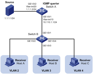
As shown in Figure 4:
· Layer 3 device Switch A runs IGMPv2 and acts as the IGMP querier. Layer 2 device Switch B runs IGMPv2 snooping.
· The multicast source sends multicast data to multicast group 224.1.1.1. Receivers Host A, Host B, and Host C belong to VLAN 2, VLAN 3, and VLAN 4, respectively.
Configure a sub-VLAN-based multicast VLAN on Switch B to meet the following requirements:
· Switch A sends the multicast data to Switch B through the multicast VLAN.
· Switch B forwards the multicast data to the receivers in different user VLANs.
Configuration procedure
1. Configure Switch A:
# Enable IP multicast routing.
<SwitchA> system-view
[SwitchA] multicast routing
[SwitchA-mrib] quit
# Create VLAN 20, and assign GigabitEthernet 1/0/2 to the VLAN.
[SwitchA] vlan 20
[SwitchA-vlan20] port gigabitethernet 1/0/2
[SwitchA-vlan20] quit
# Assign an IP address to VLAN-interface 20, and enable PIM-DM on the interface.
[SwitchA] interface vlan-interface 20
[SwitchA-Vlan-interface20] ip address 1.1.1.2 24
[SwitchA-Vlan-interface20] pim dm
[SwitchA-Vlan-interface20] quit
# Create VLAN 10.
[SwitchA] vlan 10
[SwitchA-vlan10] quit
# Configure GigabitEthernet 1/0/1 as a hybrid port, and assign the port to VLAN 10 as a tagged VLAN member.
[SwitchA] interface gigabitethernet 1/0/1
[SwitchA-GigabitEthernet1/0/1] port link-type hybrid
[SwitchA-GigabitEthernet1/0/1] port hybrid vlan 10 tagged
[SwitchA-GigabitEthernet1/0/1] quit
# Assign an IP address to VLAN-interface 10, and enable IGMP on the interface.
[SwitchA] interface vlan-interface 10
[SwitchA-Vlan-interface10] ip address 10.110.1.1 24
[SwitchA-Vlan-interface10] igmp enable
[SwitchA-Vlan-interface10] quit
2. Configure Switch B:
# Enable IGMP snooping globally.
<SwitchB> system-view
[SwitchB] igmp-snooping
[SwitchB-igmp-snooping] quit
# Create VLAN 2, assign GigabitEthernet 1/0/2 to the VLAN, and enable IGMP snooping for the VLAN.
[SwitchB] vlan 2
[SwitchB-vlan2] port gigabitethernet 1/0/2
[SwitchB-vlan2] igmp-snooping enable
[SwitchB-vlan2] quit
# Create VLAN 3, assign GigabitEthernet 1/0/3 to the VLAN, and enable IGMP snooping in the VLAN.
[SwitchB] vlan 3
[SwitchB-vlan3] port gigabitethernet 1/0/3
[SwitchB-vlan3] igmp-snooping enable
[SwitchB-vlan3] quit
# Create VLAN 4, assign GigabitEthernet 1/0/4 to the VLAN, and enable IGMP snooping in the VLAN.
[SwitchB] vlan 4
[SwitchB-vlan4] port gigabitethernet 1/0/4
[SwitchB-vlan4] igmp-snooping enable
[SwitchB-vlan4] quit
# Create VLAN 10, and enable IGMP snooping for the VLAN.
[SwitchB] vlan 10
[SwitchB-vlan10] igmp-snooping enable
[SwitchB-vlan10] quit
# Configure GigabitEthernet 1/0/1 as a hybrid port, and assign the port to VLAN 10 as a tagged VLAN member.
[SwitchB] interface gigabitethernet 1/0/1
[SwitchB-GigabitEthernet1/0/1] port link-type hybrid
[SwitchB-GigabitEthernet1/0/1] port hybrid vlan 10 tagged
[SwitchB-GigabitEthernet1/0/1] quit
# Configure VLAN 10 as a multicast VLAN, and assign VLAN 2 through VLAN 4 as sub-VLANs to multicast VLAN 10.
[SwitchB] multicast-vlan 10
[SwitchB-mvlan-10] subvlan 2 to 4
[SwitchB-mvlan-10] quit
Verifying the configuration
# Display information about all multicast VLANs on Switch B.
[SwitchB] display multicast-vlan
Total 1 multicast VLANs.
Multicast VLAN 10:
Sub-VLAN list(3 in total):
2-4
Port list(0 in total):
# Display information about multicast groups in multicast VLANs on Switch B.
[SwitchB] display multicast-vlan group
Total 1 entries.
Multicast VLAN 10: Total 1 entries.
(0.0.0.0, 224.1.1.1)
Sub-VLANs (3 in total):
VLAN 2
VLAN 3
VLAN 4
The output shows that multicast group 224.1.1.1 belongs to multicast VLAN 10. Multicast VLAN 10 contains sub-VLANs VLAN 2 through VLAN 4. Switch B will replicate the multicast data of VLAN 10 to VLAN 2 through VLAN 4.
Port-based multicast VLAN configuration example
Network requirements
As shown in Figure 5:
· Layer 3 device Switch A runs IGMPv2 and acts as the IGMP querier. Layer 2 device Switch B runs IGMPv2 snooping.
· The multicast source sends multicast data to multicast group 224.1.1.1. Receivers Host A, Host B, and Host C belong to VLAN 2, VLAN 3, and VLAN 4, respectively.
Configure a port-based multicast VLAN on Switch B to meet the following requirements:
· Switch A sends multicast data to Switch B through the multicast VLAN.
· Switch B forwards the multicast data to the receivers in different user VLANs.
Configuration procedure
1. Configure Switch A:
# Enable IP multicast routing.
<SwitchA> system-view
[SwitchA] multicast routing
[SwitchA-mrib] quit
# Create VLAN 20, and assign GigabitEthernet 1/0/2 to the VLAN.
[SwitchA] vlan 20
[SwitchA-vlan20] port gigabitethernet 1/0/2
[SwitchA-vlan20] quit
# Assign an IP address to VLAN-interface 20, and enable PIM-DM on the interface.
[SwitchA] interface vlan-interface 20
[SwitchA-Vlan-interface20] ip address 1.1.1.2 24
[SwitchA-Vlan-interface20] pim dm
[SwitchA-Vlan-interface20] quit
# Create VLAN 10, and assign GigabitEthernet 1/0/1 to the VLAN.
[SwitchA] vlan 10
[SwitchA-vlan10] port gigabitethernet 1/0/1
[SwitchA-vlan10] quit
# Assign an IP address to VLAN-interface 10, and enable IGMP on the interface.
[SwitchA] interface vlan-interface 10
[SwitchA-Vlan-interface10] ip address 10.110.1.1 24
[SwitchA-Vlan-interface10] igmp enable
[SwitchA-Vlan-interface10] quit
2. Configure Switch B:
# Enable IGMP snooping globally.
<SwitchB> system-view
[SwitchB] igmp-snooping
[SwitchB-igmp-snooping] quit
# Create VLAN 10, assign GigabitEthernet 1/0/1 to the VLAN, and enable IGMP snooping for the VLAN.
[SwitchB] vlan 10
[SwitchB-vlan10] port gigabitethernet 1/0/1
[SwitchB-vlan10] igmp-snooping enable
[SwitchB-vlan10] quit
# Create VLAN 2, and enable IGMP snooping for the VLAN.
[SwitchB] vlan 2
[SwitchB-vlan2] igmp-snooping enable
[SwitchB-vlan2] quit
# Create VLAN 3, and enable IGMP snooping for the VLAN.
[SwitchB] vlan 3
[SwitchB-vlan3] igmp-snooping enable
[SwitchB-vlan3] quit
# Create VLAN 4, and enable IGMP snooping for the VLAN.
[SwitchB] vlan 4
[SwitchB-vlan4] igmp-snooping enable
[SwitchB-vlan4] quit
# Configure GigabitEthernet 1/0/2 as a hybrid port, and configure VLAN 2 as the PVID of the hybrid port.
[SwitchB] interface gigabitethernet 1/0/2
[SwitchB-GigabitEthernet1/0/2] port link-type hybrid
[SwitchB-GigabitEthernet1/0/2] port hybrid pvid vlan 2
# Assign GigabitEthernet 1/0/2 to VLAN 2 and VLAN 10 as an untagged VLAN member.
[SwitchB-GigabitEthernet1/0/2] port hybrid vlan 2 untagged
[SwitchB-GigabitEthernet1/0/2] port hybrid vlan 10 untagged
[SwitchB-GigabitEthernet1/0/2] quit
# Configure GigabitEthernet 1/0/3 as a hybrid port, and configure VLAN 3 as the PVID of the hybrid port.
[SwitchB] interface gigabitethernet 1/0/3
[SwitchB-GigabitEthernet1/0/3] port link-type hybrid
[SwitchB-GigabitEthernet1/0/3] port hybrid pvid vlan 3
# Assign GigabitEthernet 1/0/3 to VLAN 3 and VLAN 10 as an untagged VLAN member.
[SwitchB-GigabitEthernet1/0/3] port hybrid vlan 3 untagged
[SwitchB-GigabitEthernet1/0/3] port hybrid vlan 10 untagged
[SwitchB-GigabitEthernet1/0/3] quit
# Configure GigabitEthernet 1/0/4 as a hybrid port, and configure VLAN 4 as the PVID of the hybrid port.
[SwitchB] interface gigabitethernet 1/0/4
[SwitchB-GigabitEthernet1/0/4] port link-type hybrid
[SwitchB-GigabitEthernet1/0/4] port hybrid pvid vlan 4
# Assign GigabitEthernet 1/0/4 to VLAN 4 and VLAN 10 as an untagged VLAN member.
[SwitchB-GigabitEthernet1/0/4] port hybrid vlan 4 untagged
[SwitchB-GigabitEthernet1/0/4] port hybrid vlan 10 untagged
[SwitchB-GigabitEthernet1/0/4] quit
# Configure VLAN 10 as a multicast VLAN.
[SwitchB] multicast-vlan 10
# Assign GigabitEthernet 1/0/2 and GigabitEthernet 1/0/3 to VLAN 10.
[SwitchB-mvlan-10] port gigabitethernet 1/0/2 to gigabitethernet 1/0/3
[SwitchB-mvlan-10] quit
# Assign GigabitEthernet 1/0/4 to VLAN 10.
[SwitchB] interface gigabitethernet 1/0/4
[SwitchB-GigabitEthernet1/0/4] port multicast-vlan 10
[SwitchB-GigabitEthernet1/0/4] quit
Verifying the configuration
# Display information about multicast VLANs on Switch B.
[SwitchB] display multicast-vlan
Total 1 multicast VLANs.
Multicast VLAN 10:
Sub-VLAN list(0 in total):
Port list(3 in total):
GE1/0/2
GE1/0/3
GE1/0/4
# Display dynamic IGMP snooping forwarding entries on Switch B.
[SwitchB] display igmp-snooping group
Total 1 entries.
VLAN 10: Total 1 entries.
(0.0.0.0, 224.1.1.1)
Host slots (0 in total):
Host ports (3 in total):
GE1/0/2 (00:03:23)
GE1/0/3 (00:04:07)
GE1/0/4 (00:04:16)
The output shows that IGMP snooping maintains the user ports in the multicast VLAN (VLAN 10). Switch B will forward the multicast data of VLAN 10 through these user ports.