- Table of Contents
- Related Documents
-
| Title | Size | Download |
|---|---|---|
| 02-MDC configuration | 305.07 KB |
Default MDC and non-default MDCs
Feature and hardware compatibility
Assigning hardware resources to an MDC
Assigning LPUs and interfaces to an MDC
Specifying a CPU weight for an MDC
Specifying a disk space percentage for an MDC
Specifying a memory space percentage for an MDC
Displaying and maintaining MDCs
MDC configuration example (in standalone mode)
MDC configuration example (in IRF mode)
Configuring MDCs
Overview
The Multitenant Device Context (MDC) technology can partition a physical device or an IRF fabric into multiple logical switches called MDCs. Each MDC uses its own hardware and software resources, runs independently of other MDCs, and provides services for its own customer. Creating, starting, rebooting, or deleting an MDC does not affect any other MDCs. From the user's perspective, an MDC is a standalone physical device.
Each MDC is isolated from the other MDCs on the same physical device and cannot directly communicate with them. To allow two MDCs on the same physical device to communicate, you must physically connect a port allocated to one MDC to a port allocated to the other MDC.
To manage the MDCs on the same physical device, you only need to log in to the physical device.
Using MDC together with the IRF technology, you can improve network resource efficiency while integrating network resources.
MDC applications
As shown in Figure 1, LAN 1, LAN 2, and LAN 3 are three companies' LANs. To provide access service for the three companies, you can deploy a single physical device and configure an MDC for each company on the device. Then, the administrators of each company can log in only to their own MDC to maintain their own network, without affecting any other MDCs or networks. This has the same effect as deploying a separate gateway for each company.
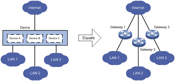
Default MDC and non-default MDCs
A device that supports MDCs is called the default MDC (for example, Device in Figure 1). The default MDC always uses the name Admin and the ID 1. You cannot delete it or change its name or ID.
When you log in to the physical device, you are logged in to the default MDC. Configuring the physical device is the same as configuring the default MDC.
On the default MDC, you can perform the following tasks:
· Manage the entire physical device.
· Create and delete non-default MDCs (for example, Device A, Device B, and Device C in Figure 1).
· Assign resources to non-default MDCs. These resources include interfaces, CPU resources, disk space, and memory space.
No MDCs can be created on a non-default MDC. Administrators of non-default MDCs can only manage and maintain their respective MDCs.
A non-default MDC can use only the resources assigned to it. It cannot use the resources assigned to other MDCs or the remaining resources on the physical device. Resources that are not assigned to any non-default MDC belong to the default MDC.
All commands in this chapter are supported on the default MDC, except for the switchback command. Non-default MDCs support only the following commands: display mdc, display mdc interface, display mdc resource, and switchback.
Unless otherwise stated, the term "MDC" refers to a non-default MDC in the following sections.
Feature and hardware compatibility
MDC is not supported on S7503E-M switches.
MDC configuration guidelines
You must install a valid license to use the MDC feature. After the license expires or is uninstalled, you cannot create, start, or use non-default MDCs. For more information about licenses, see "Managing licenses."
Do not configure MDCs on a device installed with the following cards, or install the following cards on a device configured with MDCs:
· EB interface modules.
· SC interface modules LSQ3GV48SC0 and LSQ1TGS8SC0.
· SD interface modules.
When you configure MDCs on an IRF fabric, also follow these guidelines:
· To configure MDCs for a device that you want to add to an IRF fabric, add the device to the IRF fabric before configuring MDCs. After a device joins an IRF fabric, it reboots and loads the master's configuration instead of its own.
· On an IRF fabric that has more than two member devices, you can configure only one non-default MDC.
· To forward traffic between member devices, an MDC established across members must have IRF links in up state between the default MDCs on the members.
· Assigning an IRF physical interface of the default MDC to a non-default MDC clears all IRF settings on the interface and disconnects the IRF link. To avoid IRF fabric split, make sure there are IRF links in up state between the member devices at any time.
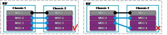
· For an IRF link to be established correctly, make sure the two IRF physical interfaces belong to the same MDC.
Figure 2 Two IRF physical interfaces of an IRF link must belong to the same MDC
· To remove an LPU where an IRF physical interface of a non-default MDC resides, first undo the IRF physical interface configuration and save the running configuration.
· To delete an MDC to which an IRF physical interface belongs, first undo the IRF physical interface configuration and save the running configuration.
For more information about IRF, see "IRF overview" and "Setting up an IRF fabric."
MDC configuration task list
|
Tasks at a glance |
|
(Required.) Creating an MDC |
|
Assigning hardware resources to an MDC: · (Required.) Assigning LPUs and interfaces to an MDC · (Optional.) Specifying a CPU weight for an MDC · (Optional.) Specifying a disk space percentage for an MDC · (Optional.) Specifying a memory space percentage for an MDC |
|
(Required.) Starting an MDC |
|
(Required.) Accessing an MDC |
|
(Optional.) Deleting an MDC |
You can assign hardware resources to MDCs before or after you start the MDCs. As a best practice, assign MDCs resources before starting them.
All MDC configuration tasks are available only on the default MDC.
Creating an MDC
|
Step |
Command |
Remarks |
|
1. Enter system view. |
system-view |
N/A |
|
2. Create an MDC. |
mdc mdc-name [ id mdc-id ] |
By default, there is a default MDC with the name Admin and ID 1. The default MDC is system defined. You cannot delete it. The MDC starts to work after you execute the mdc start command. |
Assigning hardware resources to an MDC
When you create an MDC, the system automatically assigns CPU and memory space resources on the MPUs to the MDC to ensure its operation. You can adjust the resource allocations as required.
The system does not automatically assign LPUs or interfaces to a non-default MDC. A non-default MDC cannot access any resources on LPUs by default. For a non-default MDC to forward traffic, you must assign LPUs and interfaces to the MDC.
The console port belongs to the default MDC. You cannot assign it to a non-default MDC.
The physical management Ethernet interfaces belong to the default MDC and cannot be assigned to a non-default MDC. When a non-default MDC is created, the system automatically creates one virtual management Ethernet interface for each physical management Ethernet interface.
· A virtual management Ethernet interface uses the same interface number, physical port, and link as its corresponding physical management Ethernet interface.
· You can assign IP addresses to the virtual management Ethernet interfaces for access to the MDC. The IP addresses for the virtual management Ethernet interfaces can belong to different subnets.
· To use the shutdown command to shut down a management Ethernet interface, you must be on the default MDC.
Assigning LPUs and interfaces to an MDC
Assignment restrictions and guidelines
When you assign interfaces to MDCs, follow these guidelines:
· You can assign multiple interfaces to a non-default MDC. A physical interface can belong to only one MDC.
· A physical interface must meet the following requirements to be assigned to a non-default MDC:
? The interface is not the console port or management Ethernet interface.
? The interface belongs to the default MDC.
If the interface has been assigned to another non-default MDC, you must first reclaim the interface to return the interface to the default MDC.
? The interface is not a 10-GE or 40-GE interface on an LSQM2MPUD0 or LSQM1SRP8X2QE0 MPU.
MPUs cannot be assigned to a non-default MDC.
· All interfaces on an LPU belong to the same interface group. They must be assigned to the same MDC at the same time.
· To configure a physical interface assigned to an MDC, you must log in to the MDC.
Assignment procedure
To assign LPUs and interfaces to an MDC:
|
Step |
Command |
Remarks |
|
1. Enter system view. |
system-view |
N/A |
|
2. Display the MDC to which the LPU belongs. |
display mdc [ name mdc-name ] interface |
N/A |
|
3. Enter the MDC view of the MDC. |
mdc mdc-name [ id mdc-id ] |
N/A |
|
4. Reclaim the LPU from the MDC. |
· In standalone mode: · In IRF mode: |
By default, all LPUs of the device belong to the default MDC. This step is required even if the LPU belongs to the default MDC. |
|
5. (Optional.) Reclaim interfaces from the MDC. |
· Reclaim individual
interfaces: · Reclaim a range
of interfaces: |
By default, all physical interfaces belong to the default MDC. A non-default MDC cannot use any physical interfaces. Reclaimed interfaces belong to the default MDC. This command is not supported on the default MDC. |
|
6. Exit to system view. |
quit |
N/A |
|
7. Enter the MDC view of the target non-default MDC. |
mdc mdc-name [ id mdc-id ] |
N/A |
|
8. Assign physical interfaces to the MDC. |
· Assign individual interfaces: · Assign a range of interfaces: |
Use either or both of the commands. By default, all physical interfaces belong to the default MDC. A non-default MDC cannot use any physical interfaces. This command is not supported on the default MDC. |
|
9. Assign LPUs to the MDC. |
· In standalone mode: · In IRF mode: |
By default, all LPUs of the device belong to the default MDC. A non-default MDC cannot use any LPUs. To assign multiple LPUs to the MDC, repeat this step. |
Assigning PEXs to an MDC
Assignment restrictions and guidelines
This feature is supported in an IRF system.
A PEX can be assigned to only one MDC. A tier-2 PEX must be assigned to the same MDC as the tier-1 PEX.
Assigning a PEX to an MDC assigns all interfaces on the PEX to the MDC.
After you assign PEXs to MDCs, complete PEX configuration tasks, for example, configure cascade ports and assign virtual chassis numbers. For more information, see IRF configuration in Virtual Technologies Configuration Guide.
Preparing for PEX assignment
Before assigning PEXs to MDCs, perform the following tasks:
· Identify the PEXs to be assigned.
· Identify the MDCs to which you want to assign PEXs.
· Identify the parent devices' physical interfaces to which the level-1 PEXs are attached, and assign the interfaces and the LPUs that hold the interfaces to the MDCs.
· Reclaim the PEXs from the default MDC.
Assignment procedure
To assign PEXs to an MDC:
|
Step |
Command |
Remarks |
|
1. Enter system view. |
system-view |
N/A |
|
2. Enter the view of the default MDC. |
mdc Admin |
N/A |
|
3. Reclaim PEXs from the default MDC. |
undo location pex chassis-list |
By default, all PEXs belong to the default MDC. |
|
4. Exit to system view. |
quit |
N/A |
|
5. Enter the MDC view of the target non-default MDC. |
mdc mdc-name [ id mdc-id ] |
N/A |
|
6. Assign the PEXs to the MDC. |
location pex chassis-list |
By default, a non-default MDC cannot use any PEXs. |
Specifying a CPU weight for an MDC
To ensure correct operation of all MDCs, assign them CPU weights. All MDCs share the CPU resources of the MPUs on the device. If one MDC occupies too many CPU resources, the other MDCs might not be able to operate.
The amount of CPU resources an MDC can use depends on the percentage of its CPU weight among the CPU weights of all MDCs that share the same CPU. For example, if three MDCs share the same CPU, setting their weights to 10, 10, and 5 is equivalent to setting their weights to 2, 2, and 1.
· The two MDCs with the same weight can use the CPU for approximately the same period of time.
· The third MDC can use the CPU for approximately half of the time for each of the other two MDCs.
The CPU weight setting for an MDC applies to all cards that the MDC can use, including the MPUs and the assigned LPUs.
To specify a CPU weight for an MDC:
|
Step |
Command |
Remarks |
|
1. Enter system view. |
system-view |
N/A |
|
2. Enter MDC view. |
mdc mdc-name [ id mdc-id ] |
N/A |
|
3. Specify a CPU weight for the MDC. |
limit-resource cpu weight weight-value |
The defaults are as follows: · The default MDC has a CPU weight of 10 on each MPU. · Each non-default MDC has a CPU weight of 10 on each MPU. The CPU weight for the default MDC is fixed at 10 and cannot be changed. |
Specifying a disk space percentage for an MDC
Restrictions and guidelines
The MDCs on a device share and compete for the disk space on the device's storage media. If an MDC occupies too much disk space, the other MDCs might not be able to save information such as configuration files and system logs. To avoid this problem, specify a disk space percentage for each MDC.
Before you specify a disk space percentage for an MDC, use the display mdc resource command to view how much disk space the MDC is using. The disk space you assign to an MDC must be greater than the disk space the MDC is using. If not, the MDC cannot apply for more disk space and no additional folders or files can be created or saved for the MDC.
If a card has more than one storage medium, the disk space percentage specified for an MDC takes effect on all the media.
Assignment procedure
To specify a disk space percentage for an MDC:
|
Step |
Command |
Remarks |
|
1. Enter system view. |
system-view |
N/A |
|
2. Enter MDC view. |
mdc mdc-name [ id mdc-id ] |
N/A |
|
3. Specify a disk space percentage for the MDC. |
· In standalone mode: · In IRF mode: |
By default, all MDCs share the disk space in the system, and an MDC can use all free disk space in the system. |
Specifying a memory space percentage for an MDC
The MDCs on a device share and compete for the system memory space. If an MDC occupies too much memory space, the other MDCs might not be able to operate correctly. To avoid this problem, specify a memory space percentage for each MDC.
Before you specify a memory space percentage for an MDC, use the display mdc resource command to view how much memory space the MDC is using. Make sure the memory space you assign to an MDC is sufficient for the MDC to operate correctly.
To specify a memory space percentage for an MDC:
|
Step |
Command |
Remarks |
|
1. Enter system view. |
system-view |
N/A |
|
2. Enter MDC view. |
mdc mdc-name [ id mdc-id ] |
N/A |
|
3. Specify a memory space percentage for the MDC. |
· In standalone mode: · In IRF mode: |
By default, all MDCs share the memory space in the system, and an MDC can use all free memory space in the system. |
Starting an MDC
For an MDC to operate, you must start the MDC. Starting an MDC is the same as powering on a device.
After you start an MDC, the MDC first starts the automatic configuration process. To identify whether the process is completed, use the switchto mdc command to log in to the MDC. If the resources for automatic configuration are not available, stop the automatic configuration process as prompted. For more information about automatic configuration, see "Using automatic configuration."
To start an MDC:
|
Step |
Command |
|
1. Enter system view. |
system-view |
|
2. Enter MDC view. |
mdc mdc-name [ id mdc-id ] |
|
3. Start the MDC. |
mdc start |
Accessing an MDC
A non-default MDC operates in the same way as a standalone device. From the system view of the default MDC, you can log in to a non-default MDC and enter MDC system view. To allow administrators of an MDC to log in to the MDC by using Telnet or SSH, you must complete one of the following tasks in MDC system view:
· Assign an IP address to the management Ethernet interface.
· Create a VLAN interface on the MDC and assign an IP address to the interface.
To return from an MDC to the default MDC, use the switchback or quit command.
To log in to a non-default MDC from the system view of the default MDC:
|
Step |
Command |
Remarks |
|
1. Enter system view. |
system-view |
N/A |
|
2. Log in to an MDC. |
switchto mdc mdc-name |
You can use this command to log in only to an MDC that is in active state. |
Deleting an MDC
To delete an MDC, strictly follow the procedure described below. If you fail to follow the procedure, the LPUs assigned to the MDC might not be available for re-allocation.
To delete an MDC:
|
Step |
Command |
Remarks |
|
1. Enter system view. |
system-view |
N/A |
|
2. Enter MDC view. |
mdc mdc-name [ id mdc-id ] |
N/A |
|
3. Display the running configuration on the MDC. |
display this |
N/A |
|
4. Stop the MDC. |
undo mdc start |
N/A |
|
5. Identify whether the MDC has IRF physical interfaces. |
display irf link |
If yes, use the undo port group command to remove the IRF port binding. |
|
6. Reclaim all LPUs assigned to the MDC. |
undo location |
N/A |
|
7. Reclaim all physical interfaces assigned to the MDC. |
undo allocate interface |
N/A |
|
8. Delete the MDC. |
undo mdc |
N/A |
Displaying and maintaining MDCs
Execute display commands in any view on the default MDC:
|
Task |
Command |
|
Display MDCs and their status. |
display mdc [ name mdc-name ] |
|
Display the interfaces of MDCs. |
display mdc [ name mdc-name ] interface |
|
Display the CPU, disk space, and memory space usage of MDCs. (In standalone mode.) |
display mdc [ name mdc-name ] resource [ cpu | disk | memory ] [ slot slot-number ] |
|
Display the CPU, disk space, and memory space usage of MDCs. (In IRF mode.) |
display mdc [ name mdc-name ] resource [ cpu | disk | memory ] [ chassis chassis-number slot slot-number ] |
Execute display commands in any view on a non-default MDC:
|
Task |
Command |
|
Display the ID, name, and status of the MDC. |
display mdc |
|
Display the interfaces of the MDC. |
display mdc interface |
|
Display the CPU, disk space, and memory space usage of the MDC. (In standalone mode.) |
display mdc resource [ cpu | disk | memory ] [ slot slot-number ] |
|
Display the CPU, disk space, and memory space usage of the MDC. (In IRF mode.) |
display mdc resource [ cpu | disk | memory ] [ chassis chassis-number slot slot-number ] |
MDC configuration examples
MDC configuration example (in standalone mode)
Network requirements
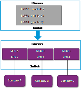
As shown in Figure 3, a service provider wants to use the device to meet the Internet access requirements of three companies.
· Company A is a network service provider and has a data center. It has a lot of servers and storage devices, and has a large amount of traffic.
· Company B and Company C are financial companies. Each of them requires a separate Internet gateway and has higher security and availability requirements.
· Company C has less Internet traffic.
Configure an MDC for each company to meet the Internet access requirements.
Configuration procedure
1. Configure the Telnet service on the device to allow Telnet login to the default MDC:
# Assign an IP address to the management interface of the device.
<Device> system-view
[Device] interface M-GigabitEthernet 0/0/0
[Device-M-GigabitEthernet0/0/0] ip address 192.168.0.250 16
[Device-M-GigabitEthernet0/0/0] quit
# Enable Telnet service.
[Device] telnet server enable
[Device] user-interface vty 0 15
[Device-ui-vty0-15] authentication-mode none
[Device-ui-vty0-15] user-role network-admin
[Device-ui-vty0-15] quit
2. Reclaim the LPUs to be assigned to the target MDCs. In this example, the LPUs belong to the default MDC.
[Device] mdc Admin
[Device-mdc-1-Admin] undo location slot 2
The configuration associated with the specified slot of MDC will be lost. Continue? [Y/N]:y
[Device-mdc-1-Admin] undo location slot 3
The configuration associated with the specified slot of MDC will be lost. Continue? [Y/N]:y
[Device-mdc-1-Admin] undo location slot 4
The configuration associated with the specified slot of MDC will be lost. Continue? [Y/N]:y
[Device-mdc-1-Admin] quit
3. Create and configure MDCA for Company A:
# Create MDCA.
<Device> system-view
[Device] mdc MDCA
It will take some time to create MDC...
MDC created successfully.
# Assign interfaces GigabitEthernet 2/0/1 through GigabitEthernet 2/0/44 and Ten-GigabitEthernet 2/0/45 through Ten-GigabitEthernet 2/0/48 to MDCA.
[Device-mdc-2-MDCA] allocate interface GigabitEthernet 2/0/1 to GigabitEthernet 2/0/44 Ten-GigabitEthernet 2/0/45 to Ten-GigabitEthernet 2/0/48
The configurations of the interfaces will be lost. Continue? [Y/N]:y
# Assign the LPU in slot 2 to MDCA.
[Device-mdc-2-MDCA] location slot 2
# Start MDCA.
[Device-mdc-2-MDCA] mdc start
It will take some time to start MDC...
MDC started successfully.
[Device-mdc-2-MDCA] quit
# Log in to MDCA from the default MDC.
[Device] switchto mdc MDCA
******************************************************************************
* Copyright (c) 2004-2018 New H3C Technologies Co., Ltd. All rights reserved.*
* Without the owner's prior written consent, *
* no decompiling or reverse-engineering shall be allowed. *
******************************************************************************
<Device> system-view
# Change the device name to MDCA for easy identification of the MDC.
[Device] sysname MDCA
# Assign an IP address to the management interface for MDCA.
[MDCA] interface M-GigabitEthernet 0/0/0
[MDCA-M-GigabitEthernet0/0/0] ip address 192.168.1.251 24
[MDCA-M-GigabitEthernet0/0/0] quit
# Configure the Telnet service to allow Telnet login to MDCA.
[MDCA] telnet server enable
[MDCA] user-interface vty 0 15
[MDCA-ui-vty0-15] authentication-mode none
[MDCA-ui-vty0-15] user-role mdc-admin
# Return to the default MDC.
[MDCA-ui-vty0-15] return
<MDCA> switchback
[Device]
4. Create and configure MDCB for Company B:
# Create MDCB.
[Device] mdc MDCB
It will take some time to create MDC...
MDC created successfully.
# Assign interfaces GigabitEthernet 3/0/1 through GigabitEthernet 3/0/44 and Ten-GigabitEthernet 3/0/45 through Ten-GigabitEthernet 3/0/48 to MDCB.
[Device-mdc-3-MDCB] allocate interface GigabitEthernet 3/0/1 to GigabitEthernet 3/0/44 Ten-GigabitEthernet 3/0/45 to Ten-GigabitEthernet 3/0/48
The configurations of the interfaces will be lost. Continue? [Y/N]:y
# Assign the LPU in slot 3 to MDCB.
[Device-mdc-3-MDCB] location slot 3
# Start MDCB.
[Device-mdc-3-MDCB] mdc start
It will take some time to start MDC...
MDC started successfully.
[Device-mdc-3-MDCB] quit
# Log in to MDCB from the default MDC.
[Device] switchto mdc MDCB
******************************************************************************
* Copyright (c) 2004-2018 New H3C Technologies Co., Ltd. All rights reserved.*
* Without the owner's prior written consent, *
* no decompiling or reverse-engineering shall be allowed. *
******************************************************************************
<Device> system-view
# Change the device name to MDCB for easy identification of the MDC.
[Device] sysname MDCB
# Assign an IP address to the management interface for MDCB.
[MDCB] interface M-GigabitEthernet 0/0/0
[MDCB-M-GigabitEthernet0/0/0] ip address 192.168.2.251 24
[MDCB-M-GigabitEthernet0/0/0] quit
# Configure the Telnet service to allow Telnet login to MDCB.
[MDCB] telnet server enable
[MDCB] user-interface vty 0 15
[MDCB-ui-vty0-15] authentication-mode none
[MDCB-ui-vty0-15] user-role mdc-admin
# Return to the default MDC.
[MDCB-ui-vty0-15] return
<MDCB> switchback
[Device]
5. Create and configure MDCC for Company C:
# Create MDCC.
[Device] mdc MDCC
It will take some time to create MDC...
MDC created successfully.
# Assign interfaces GigabitEthernet 4/0/1 through GigabitEthernet 4/0/44 and Ten-GigabitEthernet 4/0/45 through Ten-GigabitEthernet 4/0/48 to MDCC.
[Device-mdc-3-MDCC] allocate interface GigabitEthernet 4/0/1 to GigabitEthernet 4/0/44 Ten-GigabitEthernet 4/0/45 to Ten-GigabitEthernet 4/0/48
The configurations of the interfaces will be lost. Continue? [Y/N]:y
# Assign the LPU in slot 4 to MDCC.
[Device-mdc-4-MDCC] location slot 4
# Start MDCC.
[Device-mdc-4-MDCC] mdc start
It will take some time to start MDC...
MDC started successfully.
[Device-mdc-4-MDCC] quit
# Log in to MDCC from the default MDC.
[Device] switchto mdc MDCC
******************************************************************************
* Copyright (c) 2004-2018 New H3C Technologies Co., Ltd. All rights reserved.*
* Without the owner's prior written consent, *
* no decompiling or reverse-engineering shall be allowed. *
******************************************************************************
<Device> system-view
# Change the device name to MDCC for easy identification of the MDC.
[Device] sysname MDCC
# Assign an IP address to the management interface for MDCC.
[MDCC] interface M-GigabitEthernet 0/0/0
[MDCC-M-GigabitEthernet0/0/0] ip address 192.168.3.251 24
[MDCC-M-GigabitEthernet0/0/0] quit
# Configure the Telnet service to allow Telnet login to MDCC.
[MDCC] telnet server enable
[MDCC] user-interface vty 0 15
[MDCC-ui-vty0-15] authentication-mode none
[MDCC-ui-vty0-15] user-role mdc-admin
# Return to the default MDC.
[MDCC-ui-vty0-15] return
<MDCC> switchback
[Device]
Verifying the configuration
1. Verify that the MDCs exist and are operating correctly.
<Device> display mdc
ID Name Status
1 Admin active
2 MDCA active
3 MDCB active
4 MDCC active
2. Log in to MDCA as an administrator of Company A and display the running configuration.
C:\> telnet 192.168.1.251
******************************************************************************
* Copyright (c) 2004-2018 New H3C Technologies Co., Ltd. All rights reserved.*
* Without the owner's prior written consent, *
* no decompiling or reverse-engineering shall be allowed. *
******************************************************************************
<MDCA> display current-configuration
...
MDC configuration example (in IRF mode)
Network requirements
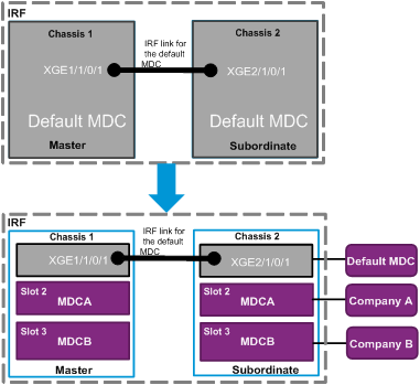
As shown in Figure 4, a service provider wants to use the IRF fabric to meet the Internet access requirements of two companies. Company A is a network service provider and has a data center. It has a lot of servers and storage devices, and has a large amount of traffic. Company B is a financial company. It requires a separate Internet gateway and has higher security and availability requirements.
The IRF fabric has two members. The master uses member ID 1. The subordinate member uses member ID 2. Each member device has one LPU in slot 2 and one LPU in slot 3. Each LPU has 16 10-GE interfaces.
Configure an MDC for each company to meet the Internet access requirements.
Configuration procedure
1. Set up an IRF fabric on the default MDC. For more information about IRF fabric setup, see "Setting up an IRF fabric."
2. Configure the Telnet service on the IRF to allow Telnet login to the default MDC:
# Assign an IP address to the management interface.
<IRF> system-view
[IRF] interface M-GigabitEthernet 1/0/0/0
[IRF-M-GigabitEthernet1/0/0/0] ip address 192.168.0.250 16
[IRF-M-GigabitEthernet1/0/0/0] quit
# Enable Telnet service.
[IRF] telnet server enable
3. Reclaim the LPUs to be assigned to the target MDCs. In this example, the LPUs belong to the default MDC.
[IRF] mdc Admin
[IRF-mdc-1-Admin] undo location chassis 1 slot 2
The configuration associated with the specified slot of MDC will be lost. Continue? [Y/N]:y
[IRF-mdc-1-Admin] undo location chassis 1 slot 3
The configuration associated with the specified slot of MDC will be lost. Continue? [Y/N]:y
[IRF-mdc-1-Admin] undo location chassis 2 slot 2
The configuration associated with the specified slot of MDC will be lost. Continue? [Y/N]:y
[IRF-mdc-1-Admin] quit
[IRF-mdc-1-Admin] undo location chassis 2 slot 3
The configuration associated with the specified slot of MDC will be lost. Continue? [Y/N]:y
[IRF-mdc-1-Admin] quit
4. Create and configure MDCA for Company A:
# Create MDCA.
<IRF> system-view
[IRF] mdc MDCA
It will take some time to create MDC...
MDC created successfully.
# Assign interfaces Ten-GigabitEthernet 1/2/0/1 through Ten-GigabitEthernet 1/2/0/16 and Ten-GigabitEthernet 2/2/0/1 through Ten-GigabitEthernet 2/2/0/16 to MDCA.
[IRF-mdc-2-MDCA] allocate interface ten-gigabitethernet 1/2/0/1 to ten-gigabitethernet 1/2/0/16
Configurations of the interfaces will be lost. Continue? [Y/N]:y
[IRF-mdc-2-MDCA] allocate interface ten-gigabitethernet 2/2/0/1 to ten-gigabitethernet 2/2/0/16
Configurations of the interfaces will be lost. Continue? [Y/N]:y
# Assign the LPU in the master's slot 2 and the LPU in the subordinate member's slot 2 to MDCA.
[IRF-mdc-2-MDCA] location chassis 1 slot 2
[IRF-mdc-2-MDCA] location chassis 2 slot 2
# Start MDCA.
[IRF-mdc-2-MDCA] mdc start
It will take some time to start MDC...
MDC started successfully.
[IRF-mdc-2-MDCA] quit
# Log in to MDCA from the default MDC.
[IRF] switchto mdc MDCA
******************************************************************************
* Copyright (c) 2004-2018 New H3C Technologies Co., Ltd. All rights reserved.*
* Without the owner's prior written consent, *
* no decompiling or reverse-engineering shall be allowed. *
******************************************************************************
<Sysname> system-view
# Set the device name to MDCA.
[Sysname] sysname MDCA
# Assign an IP address to the management interface for MDCA.
[MDCA] interface M-GigabitEthernet 1/0/0/0
[MDCA-M-GigabitEthernet1/0/0/0] ip address 192.168.1.251 24
[MDCA-M-GigabitEthernet1/0/0/0] quit
# Configure the Telnet service to allow Telnet login to MDCA.
[MDCA] telnet server enable
[MDCA] user-interface vty 0 15
[MDCA-ui-vty0-15] authentication-mode none
[MDCA-ui-vty0-15] user-role mdc-admin
# Return to the default MDC.
[MDCA-ui-vty0-15] return
<MDCA> switchback
[IRF]
5. Create and configure MDCB for Company B:
# Create MDCB.
[IRF] mdc MDCB
It will take some time to create MDC...
MDC created successfully.
# Assign interfaces Ten-GigabitEthernet 1/3/0/1 through Ten-GigabitEthernet 1/3/0/16 and Ten-GigabitEthernet 2/3/0/1 through Ten-GigabitEthernet 2/3/0/16 to MDCB.
[IRF-mdc-3-MDCB] allocate interface ten-gigabitethernet 1/3/0/1 to ten-gigabitethernet 1/3/0/16
Configurations of the interfaces will be lost. Continue? [Y/N]:y
[IRF-mdc-3-MDCB] allocate interface ten-gigabitethernet 2/3/0/1 to ten-gigabitethernet 2/3/0/16
Configurations of the interfaces will be lost. Continue? [Y/N]:y
# Assign the LPU in the master's slot 3 and the LPU in the subordinate member's slot 3 to MDCB.
[IRF-mdc-3-MDCB] location chassis 1 slot 3
[IRF-mdc-3-MDCB] location chassis 2 slot 3
# Start MDCB.
[IRF-mdc-3-MDCB] mdc start
It will take some time to start MDC...
MDC started successfully.
[IRF-mdc-3-MDCB] quit
# Log in to MDCB from the default MDC.
[IRF]switchto mdc MDCB
******************************************************************************
* Copyright (c) 2004-2018 New H3C Technologies Co., Ltd. All rights reserved.*
* Without the owner's prior written consent, *
* no decompiling or reverse-engineering shall be allowed. *
******************************************************************************
<Sysname> system-view
# Set the device name to MDCB.
[Sysname] sysname MDCB
# Assign an IP address to the management interface for MDCB.
[MDCB] interface M-GigabitEthernet 1/0/0/0
[MDCB-M-GigabitEthernet1/0/0/0] ip address 192.168.2.251 24
[MDCB-M-GigabitEthernet1/0/0/0] quit
# Configure the Telnet service to allow Telnet login to MDCB.
[MDCB] telnet server enable
[MDCB] user-interface vty 0 15
[MDCB-ui-vty0-15] authentication-mode none
[MDCB-ui-vty0-15] user-role mdc-admin
# Return to the default MDC.
[MDCB-ui-vty0-15] return
<MDCB> switchback
[IRF]
Verifying the configuration
1. Verify that the MDCs exist and are operating correctly.
<Device> display mdc
ID Name Status
1 Admin active
2 MDCA active
3 MDCB active