- Table of Contents
- Related Documents
-
| Title | Size | Download |
|---|---|---|
| 01-Text | 1.25 MB |
Contents
Configuration restrictions and guidelines
Interface backup configuration task list
Configuring strict active/standby interface backup
Explicitly specifying backup interfaces without traffic thresholds
Using interface backup with the Track module
Configuring load-shared interface backup
Displaying and maintaining interface backup
Interface backup configuration examples
Strict active/standby interface backup configuration example
Strict active/standby interface backup with the Track module configuration example
Load-shared interface backup configuration example
Configuring basic CFD settings
Configuring MIP auto-generation rules
Configuring port collaboration
Displaying and maintaining CFD
BFD session establishment and termination
BFD session modes and operating modes
Configuring BFD basic functions
Configuring control packet mode
Enabling SNMP notifications for BFD
Displaying and maintaining BFD
Collaboration application example
Associating Track with a detection module object
Associating Track with interface management
Associating Track with route management
Associating Track with a tracked list
Associating Track with a Boolean list
Associating Track with a percentage threshold list
Associating Track with a weight threshold list
Associating the Track module with an application module
Associating Track with static routing
Associating Track with interface backup
Associating Track with MPLS L2VPN
Displaying and maintaining track entries
VRRP-Track-NQA collaboration configuration example
Configuring BFD for a VRRP backup to monitor the master
Configuring BFD for the VRRP master to monitor the uplink
Static routing-Track-NQA collaboration configuration example
Static routing-Track-BFD collaboration configuration example
VRRP-Track-interface management collaboration configuration example
VRRP-Track-route management collaboration configuration example
Router priority in a VRRP group
Virtual MAC address assignment
IPv4 VRRP configuration task list
Specifying an IPv4 VRRP operating mode
Specifying the IPv4 VRRP version
Creating a VRRP group and assigning a virtual IP address
Configuring the router priority, preemptive mode, and tracking function
Configuring IPv4 VRRP packet attributes
Enabling SNMP notifications for VRRP
Displaying and maintaining IPv4 VRRP
IPv6 VRRP configuration task list
Specifying an IPv6 VRRP operating mode
Creating a VRRP group and assigning a virtual IPv6 address
Configuring the router priority, preemptive mode, and tracking function
Configuring IPv6 VRRP packet attributes
Displaying and maintaining IPv6 VRRP
IPv4 VRRP configuration examples
Single VRRP group configuration example
Multiple VRRP groups configuration example
VRRP load balancing configuration example
IPv6 VRRP configuration examples
Single VRRP group configuration example
Multiple VRRP groups configuration example
VRRP load balancing configuration example
Multiple masters appear in a VRRP group
Process placement policy and optimization
Feature and hardware compatibility
Command and hardware compatibility
Configuration restrictions and guidelines
Process placement configuration task list
Configuring process placement policy
Configuring a location affinity
Configuring a location type affinity
Configuring a process affinity
Configuration restrictions and guidelines
Setting the interval to send advertisement packets
Setting the port shutdown mode
Configuring DLDP authentication
Displaying and maintaining DLDP
Automatically shutting down unidirectional links
Manually shutting down unidirectional links
Configuring interface backup
Overview
Interface backup enables you to configure multiple backup interfaces for a Layer 3 interface to increase link availability. When the primary interface fails or is overloaded, its backup interfaces can take over or participate in traffic forwarding.
Compatible interfaces
The interface backup feature is configurable for the interfaces in Table 1.
Table 1 Interfaces that support interface backup
|
Category |
Interfaces |
Remarks |
|
Ethernet |
Layer 3 Ethernet interfaces/subinterfaces Layer 3 VE interfaces |
N/A |
|
WAN |
AM interfaces ATM interfaces ISDN BRI interfaces POS interfaces Serial interfaces (asynchronous, synchronous) |
The AM interfaces can only work as backup interfaces. All the other interfaces can work as both primary and backup interfaces. An ISDN BRI interface can work as the primary interface only when it is configured to provide leased line services. An asynchronous serial interface cannot work as the primary interface if DDR is configured on it. |
|
Others |
AUX ports Dialer interfaces MP-group interfaces Tunnel interfaces |
A dialer interface can be used as the primary interface only when it is a PPPoE client in permanent session mode. |
Backup modes
The primary interface and its backup interfaces can operate in strict active/standby mode or load sharing mode.
· Strict active/standby mode—Only one interface transmits traffic. All the other interfaces are in STANDBY state.
· Load sharing mode—Backup interfaces participate in traffic forwarding when the amount of traffic on the primary interface reaches the upper threshold. They are activated and deactivated depending on the amount of traffic.
In strict active/standby mode, traffic loss occurs when the active interface is overloaded. Load sharing mode improves link efficiency and reduces the risk of packet loss.
Strict active/standby mode
In strict active/standby mode, the primary interface always has higher priority than all backup interfaces.
· When the primary interface is operating correctly, all traffic is transmitted through the primary interface.
· When the primary interface fails, the highest-priority backup interface takes over. If the highest-priority backup interface also fails, the second highest-priority backup interface takes over, and so forth.
|
|
NOTE: If two backup interfaces have the same priority, the one configured first has preference. |
An active backup interface is always preempted by the primary interface. However, a higher-priority backup interface cannot preempt a lower-priority backup interface that has taken over the primary interface.
· The primary interface takes over when it recovers from a failure condition.
· The higher-priority backup interface cannot take over when it recovers from a failure condition while the primary interface is still down.
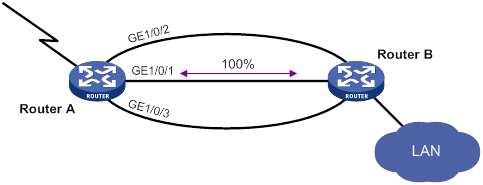
As shown in Figure 1, GigabitEthernet 1/0/1 on Router A is the primary interface. GigabitEthernet 1/0/2 (with a priority of 30) and GigabitEthernet 1/0/3 (with a priority of 20) are its backup interfaces.
· When GigabitEthernet 1/0/1 is operating correctly, all traffic is transmitted through GigabitEthernet 1/0/1.
· When GigabitEthernet 1/0/1 fails, GigabitEthernet 1/0/2 takes over because it has higher priority than GigabitEthernet 1/0/3. If GigabitEthernet 1/0/2 also fails, GigabitEthernet 1/0/3 takes over.
· When GigabitEthernet 1/0/1 is recovered, it preempts the active backup interface because it is the primary interface. If GigabitEthernet 1/0/2 is recovered while GigabitEthernet 1/0/1 is still down, GigabitEthernet 1/0/2 cannot preempt GigabitEthernet 1/0/3 to forward traffic.
Figure 1 Strict active/backup mode
Load sharing mode
In load sharing mode, the backup interfaces are activated to transmit traffic depending on the traffic load on the primary interface.
· When the amount of traffic on the primary interface exceeds the upper threshold, the backup interfaces are activated in descending order of priority. This action continues until the traffic drops below the upper threshold.
· When the total amount of traffic on all load-shared interfaces decreases below the lower threshold, the backup interfaces are deactivated in ascending order of priority. This action continues until the total amount of traffic exceeds the lower threshold.
· When the primary interface fails (in DOWN state), the strict active/standby mode applies. Only one backup interface can forward traffic.
The upper and lower thresholds are user configurable.
|
|
NOTE: · "Traffic" on an interface refers to the amount of incoming or outgoing traffic, whichever is higher. · If two backup interfaces have the same priority, the one configured first has preference. |
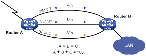
As shown in Figure 2, GigabitEthernet 1/0/1 on Router A is the primary interface. GigabitEthernet 1/0/2 (with a priority of 30) and GigabitEthernet 1/0/3 (with a priority of 20) are its backup interfaces.
· When the amount of traffic on GigabitEthernet 1/0/1 exceeds the upper threshold, GigabitEthernet 1/0/2 is activated, because it has higher priority than GigabitEthernet 1/0/3. If the amount of traffic on GigabitEthernet 1/0/1 still exceeds the upper threshold, GigabitEthernet 1/0/3 is activated.
· When the total amount of traffic on all load-shared interfaces decreases below the lower threshold, GigabitEthernet 1/0/3 is first deactivated, because its priority is lower than GigabitEthernet 1/0/2. If the total amount of traffic on GigabitEthernet 1/0/1 and GigabitEthernet 1/0/2 is still below the lower threshold, GigabitEthernet 1/0/2 is deactivated.
Configuration restrictions and guidelines
When you configure interface backup, follow these restrictions and guidelines:
· The device supports up to 10 primary interfaces.
· An interface can be configured as a backup only for one interface.
· An interface cannot be both a primary and backup interface.
· For correct traffic forwarding, make sure the primary and backup interfaces have routes to the destination network.
Interface backup configuration task list
|
Task |
Remarks |
|
Configuring strict active/standby interface backup: · (Method 1.) Explicitly specifying backup interfaces without traffic thresholds · (Method 2.) Using interface backup with the Track module |
You cannot use these two methods at the same time for a primary interface and its backup interfaces. Use method 1 if you want to monitor the interface state of the primary interface for a switchover to occur. Use method 2 if you want to monitor any other state, such as the link state of the primary interface. |
|
A primary interface and its backup interfaces operate in load sharing mode after you specify the traffic thresholds on the primary interface. This method cannot be used with the other two methods at the same time for an interface. |
Configuring strict active/standby interface backup
You can use one of the following methods to configure strict active/standby interface backup:
· Explicitly specify backup interfaces for a primary interface. If this method is used, interface backup changes the state of the backup interface in response to the interface state change of the primary interface.
· Use interface backup with the Track module. If this method is used, interface backup uses a track entry to monitor the link state of the primary interface. Interface backup changes the state of a backup interface in response to the link state change of the primary interface.
Explicitly specifying backup interfaces without traffic thresholds
For the primary and backup interfaces to operate in strict active/standby mode, do not specify the traffic thresholds on the primary interface. If the traffic thresholds are configured, the interfaces will operate in load sharing mode.
You can assign priority to backup interfaces. When the primary interface fails, the backup interfaces are activated in descending order of priority, with the highest-priority interface activated first. If two backup interfaces have the same priority, the one configured first has preference.
To prevent link flapping from causing frequent interface switchovers, you can configure the following switchover delay timers:
· Up delay timer—Number of seconds that the primary or backup interface must wait before it can come up.
· Down delay timer—Number of seconds that the active primary or backup interface must wait before it is set to down state.
When the link of the active interface fails, the interface state does not change immediately. Instead, a down delay timer starts. If the link recovers before the timer expires, the interface state does not change. If the link is still down when the timer expires, the interface state changes to down.
To configure strict active/standby interface backup for a primary interface:
|
Step |
Command |
Remarks |
|
1. Enter system view. |
system-view |
N/A |
|
2. Enter interface view. |
interface interface-type interface-number |
This interface must be the primary interface. |
|
3. Specify a backup interface. |
backup interface interface-type interface-number [ priority ] |
By default, an interface does not have any backup interfaces. Repeat this command to specify up to three backup interfaces for the interface. |
|
4. Set the switchover delay timers. |
backup timer delay up-delay down-delay |
By default, the up and down delay timers are both 5 seconds. |
Using interface backup with the Track module
To use interface backup with the Track module to provide strict active/standby backup for a primary interface:
· Configure a track entry to monitor state information of the primary interface. For example, monitor its link state.
· Associate the track entry with a backup interface.
Interface backup changes the state of the backup interface in response to the track entry state, as shown in Table 2.
Table 2 Action on the backup interface in response to the track entry state change
|
Track entry state |
State of the monitored primary link |
Action on the backup interface |
|
Positive |
The primary link is operating correctly. |
Places the backup interface in STANDBY state. |
|
Negative |
The primary link has failed. |
Activates the backup interface to take over. |
|
NotReady |
The primary link is not monitored. This situation occurs when the track module or the monitoring module is not ready, for example, because the Track module is restarting or the monitoring settings are incomplete. In this situation, interface backup cannot obtain information about the primary link from the track module. |
· If the track entry state stays in NotReady state after it is created, interface backup does not change the state of the backup interface. · If the track entry state changes to NotReady from Positive or Negative, the backup interface changes back to the forwarding state before it was used for interface backup. |
For more information about configuring a track entry, see "Configuring Track."
When you associate a backup interface with a track entry, follow these guidelines:
· You can associate an interface with only one track entry.
· You can create the associated track entry before or after the association. The association takes effect after the track entry is created.
· To maintain performance, limit the number of associations to 64.
To associate Track with an interface:
|
Step |
Command |
Remarks |
|
1. Enter system view. |
system-view |
N/A |
|
2. Enter interface view. |
interface interface-type interface-number |
This interface must be the interface you are using as a backup. |
|
3. Associate the interface with a track entry. |
backup track track-entry-number |
By default, an interface is not associated with a track entry. |
Configuring load-shared interface backup
To implement load-shared interface backup, you must configure the traffic thresholds on the primary interface. Interface backup regularly compares the amount of traffic with the thresholds to determine whether to activate or deactivate a backup interface. The traffic polling interval is user configurable.
|
|
NOTE: When configuring load-shared interface backup, you must set the maximum available bandwidth of involved logical interfaces. As a best practice, set the maximum available interface bandwidth to be less than or equal to the actual available bandwidth of the corresponding physical interface or logical link. |
You can assign priority to backup interfaces.
· When the amount of traffic on the primary interface exceeds the upper threshold, the backup interfaces are activated in descending order of priority.
· When the total amount of traffic on all load-shared interfaces decreases below the lower threshold, the backup interfaces are deactivated in ascending order of priority.
If two backup interfaces have the same priority, the one configured first has preference.
If a traffic flow has a fast forwarding entry, all packets of the flow will be forwarded out of the outgoing interface in the entry. The packets of the flow will not be distributed between interfaces when the upper threshold is reached. For more information about fast forwarding, see Layer 3—IP Services Configuration Guide.
To configure load-shared backup for an interface:
|
Step |
Command |
Remarks |
|
1. Enter system view. |
system-view |
N/A |
|
2. Enter interface view. |
interface interface-type interface-number |
You must enter the view of the primary interface. |
|
3. Configure a backup interface for the interface. |
backup interface interface-type interface-number [ priority ] |
By default, an interface does not have any backup interfaces. Repeat this command to specify up to three backup interfaces. |
|
4. Set backup load sharing thresholds. |
backup threshold upper-threshold lower-threshold |
By default, no traffic thresholds are configured. |
|
5. Set the traffic polling interval. |
backup timer flow-check interval |
The default interval is 30 seconds. |
Displaying and maintaining interface backup
Execute display commands in any view.
|
Command |
|
|
Display traffic statistics for load-shared interfaces. |
display interface-backup statistics |
|
Display the status of primary and backup interfaces. |
display interface-backup state |
Interface backup configuration examples
Strict active/standby interface backup configuration example
Network requirements
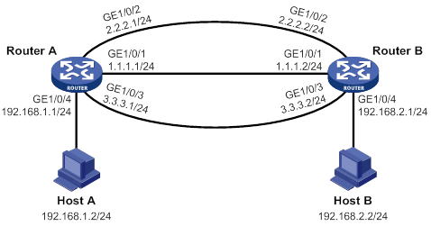
As shown in Figure 3:
· Specify GigabitEthernet 1/0/2 and GigabitEthernet 1/0/3 on Router A to back up GigabitEthernet 1/0/1.
· Assign GigabitEthernet 1/0/2 a higher priority than GigabitEthernet 1/0/3.
· Set the up and down delay timers to 10 seconds for the backup interfaces.
Configuration procedure
1. Assign IP addresses to interfaces, as shown in Figure 3. (Details not shown.)
2. Configure routes:
# On Router A, configure static routes to 192.168.2.0/24 through the primary and backup interfaces.
<RouterA> system-view
[RouterA] ip route-static 192.168.2.0 24 gigabitethernet 1/0/1 1.1.1.2
[RouterA] ip route-static 192.168.2.0 24 gigabitethernet 1/0/2 2.2.2.2
[RouterA] ip route-static 192.168.2.0 24 gigabitethernet 1/0/3 3.3.3.2
# On Router B, configure static routes to 192.168.1.0/24.
[RouterB] ip route-static 192.168.1.0 24 gigabitethernet 1/0/1 1.1.1.1
[RouterB] ip route-static 192.168.1.0 24 gigabitethernet 1/0/2 2.2.2.1
[RouterB] ip route-static 192.168.1.0 24 gigabitethernet 1/0/3 3.3.3.1
3. On Router A, configure backup interfaces and switchover delays:
# Specify GigabitEthernet 1/0/2 and GigabitEthernet 1/0/3 to back up GigabitEthernet 1/0/1, and assign them a priority of 30 and 20, respectively.
[RouterA] interface gigabitethernet 1/0/1
[RouterA-GigabitEthernet1/0/1] backup interface gigabitethernet 1/0/2 30
[RouterA-GigabitEthernet1/0/1] backup interface gigabitethernet 1/0/3 20
# Set both up and down delay timers to 10 seconds.
[RouterA-GigabitEthernet1/0/1] backup timer delay 10 10
Verifying the configuration
# Display states of the primary and backup interfaces.
[RouterA-GigabitEthernet1/0/1] display interface-backup state
Interface: GE1/0/1
UpDelay: 10 s
DownDelay: 10 s
State: UP
Backup interfaces:
GE1/0/2 Priority: 30 State: STANDBY
GE1/0/3 Priority: 20 State: STANDBY
The output shows that GigabitEthernet 1/0/1 is in UP state and the two backup interfaces are in STANDBY state.
# Shut down the primary interface GigabitEthernet 1/0/1.
[RouterA-GigabitEthernet1/0/1] shutdown
[RouterA-GigabitEthernet1/0/1] display interface-backup state
Interface: GE1/0/1
UpDelay: 10 s
DownDelay: 10 s
State: DOWN
Backup interfaces:
GE1/0/2 Priority: 30 State: UP
GE1/0/3 Priority: 20 State: STANDBY
Strict active/standby interface backup with the Track module configuration example
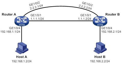
Network requirements
As shown in Figure 4, configure a track entry to monitor the link state of GigabitEthernet 1/0/1. When the link of GigabitEthernet 1/0/1 fails, the backup interface GigabitEthernet 1/0/2 comes up to take over.
Configuration procedure
1. Assign IP addresses to interfaces, as shown in Figure 4. (Details not shown.)
2. Configure routes:
# On Router A, configure static routes to 192.168.2.0/24 through the primary and backup interfaces.
<RouterA> system-view
[RouterA] ip route-static 192.168.2.0 24 gigabitethernet 1/0/1 1.1.1.2
[RouterA] ip route-static 192.168.2.0 24 gigabitethernet 1/0/2 2.2.2.2
# On Router B, configure static routes to 192.168.1.0/24.
<RouterB> system-view
[RouterB] ip route-static 192.168.1.0 24 gigabitethernet 1/0/1 1.1.1.1
[RouterB] ip route-static 192.168.1.0 24 gigabitethernet 1/0/2 2.2.2.1
3. On Router A, configure track settings:
# Configure track entry 1 to monitor the link state of GigabitEthernet 1/0/1.
[RouterA] track 1 interface gigabitethernet 1/0/1
# Associate track entry 1 with the backup interface GigabitEthernet 1/0/2.
[RouterA] interface gigabitethernet 1/0/2
[RouterA-GigabitEthernet1/0/2] backup track 1
[RouterA-GigabitEthernet1/0/2] quit
Verifying the configuration
# Verify that the backup interface GigabitEthernet 1/0/2 is in STANDBY state while the primary link is operating correctly.
[RouterA] display interface-backup state
IB Track Information:
GE1/0/2 Track: 1 State: STANDBY
# Shut down the primary interface GigabitEthernet 1/0/1.
[RouterA] interface gigabitethernet 1/0/1
[RouterA-GigabitEthernet1/0/1] shutdown
# Verify that the backup interface GigabitEthernet 1/0/2 comes up after the primary link goes down.
[RouterA-GigabitEthernet1/0/1] display interface-backup state
IB Track Information:
GE1/0/2 Track: 1 State: UP
Load-shared interface backup configuration example
Network requirements
As shown in Figure 5:
· Configure GigabitEthernet 1/0/2 and GigabitEthernet 1/0/3 on Router A to back up the primary interface GigabitEthernet 1/0/1.
· Assign GigabitEthernet 1/0/2 higher priority than GigabitEthernet 1/0/3.
· On the primary interface:
? Specify the interface bandwidth used for traffic load calculation.
? Set the upper and lower thresholds to 80 and 20, respectively.
Configuration procedure
1. Assign IP addresses to interfaces, as shown in Figure 5. (Details not shown.)
2. Configure routes:
# On Router A, configure routes to 192.168.2.0/24 through the primary and backup interfaces.
<RouterA> system-view
[RouterA] ip route-static 192.168.2.0 24 gigabitethernet 1/0/1 1.1.1.2
[RouterA] ip route-static 192.168.2.0 24 gigabitethernet 1/0/2 2.2.2.2
[RouterA] ip route-static 192.168.2.0 24 gigabitethernet 1/0/3 3.3.3.2
# On Router B, configure routes to 192.168.1.0/24.
<RouterB> system-view
[RouterB] ip route-static 192.168.1.0 24 gigabitethernet 1/0/1 1.1.1.1
[RouterB] ip route-static 192.168.1.0 24 gigabitethernet 1/0/2 2.2.2.1
[RouterB] ip route-static 192.168.1.0 24 gigabitethernet 1/0/3 3.3.3.1
3. On Router A, configure backup interfaces and traffic thresholds:
# Specify GigabitEthernet 1/0/2 and GigabitEthernet 1/0/3 to back up GigabitEthernet 1/0/1, and assign them with a priority of 30 and 20, respectively.
[RouterA] interface gigabitethernet 1/0/1
[RouterA-GigabitEthernet1/0/1] backup interface gigabitethernet 1/0/2 30
[RouterA-GigabitEthernet1/0/1] backup interface gigabitethernet 1/0/3 20
# Set the expected bandwidth to 10000 kbps on the primary interface.
[RouterA-GigabitEthernet1/0/1] bandwidth 10000
# Set the upper and lower thresholds to 80 and 20, respectively.
[RouterA-GigabitEthernet1/0/1] backup threshold 80 20
Verifying the configuration
# Display traffic statistics for load-shared interfaces.
[RouterA-GigabitEthernet1/0/1] display interface-backup statistics
Interface: GigabitEthernet1/0/1
Statistics interval: 30 s
Bandwidth: 10000000 bps
PrimaryTotalIn: 102 bytes
PrimaryTotalOut: 108 bytes
PrimaryIntervalIn: 102 bytes
PrimaryIntervalOut: 108 bytes
Primary used bandwidth: 28 bps
TotalIn: 102 bytes
TotalOut: 108 bytes
TotalIntervalIn: 102 bytes
TotalIntervalOut: 108 bytes
Total used bandwidth: 28 bps
The output shows that the upper traffic threshold has not been exceeded. All traffic is transmitted through the primary interface GigabitEthernet 1/0/1.
# Verify that both backup interfaces are in STANDBY state because the upper threshold has not been exceeded.
[RouterA-GigabitEthernet1/0/1] display interface-backup state
Interface: GE1/0/1
UpDelay: 5 s
DownDelay: 5 s
Upper threshold: 80
Lower threshold: 20
State: UP
Backup interfaces:
GE1/0/2 Priority: 30 State: STANDBY
GE1/0/3 Priority: 20 State: STANDBY
# Increase the incoming or outgoing traffic rate to be higher than 8000 kbps (80% of the specified bandwidth) on the primary interface. (Details not shown.)
# Verify that the backup interface GigabitEthernet 1/0/2 comes up to participate in traffic forwarding, because it has higher priority than GigabitEthernet 1/0/3.
[RouterA-GigabitEthernet1/0/1] display interface-backup state
Interface: GE1/0/1
UpDelay: 5 s
Upper threshold: 80
Lower threshold: 20
State: UP
Backup interfaces:
GE1/0/2 Priority: 30 State: UP
GE1/0/3 Priority: 20 State: STANDBY
Configuring CFD
Overview
Connectivity Fault Detection (CFD), which conforms to IEEE 802.1ag Connectivity Fault Management (CFM) and ITU-T Y.1731, is an end-to-end link layer OAM mechanism. CFD is used for link connectivity detection, fault verification, and fault location in Ethernet networks and MPLS Layer 2 VPNs. For information about MPLS Layer 2 VPNs, see MPLS Configuration Guide.
Basic CFD concepts
Maintenance domain
A maintenance domain (MD) defines the network or part of the network where CFD plays its role. An MD is identified by its MD name.
To accurately locate faults, CFD introduces eight levels (from 0 to 7) to MDs. The bigger the number, the higher the level and the larger the area covered. Domains can touch or nest (if the outer domain has a higher level than the nested one) but cannot intersect or overlap.
MD levels facilitate fault location and make fault location more accurate. As shown in Figure 6, MD_A in light blue nests MD_B in dark blue. If a connectivity fault is detected at the boundary of MD_A, any of the devices in MD_A, including Device A through Device E, might fail. If a connectivity fault is also detected at the boundary of MD_B, the failure points can be any of Device B through Device D. If the devices in MD_B can operate correctly, at least Device C is operational.
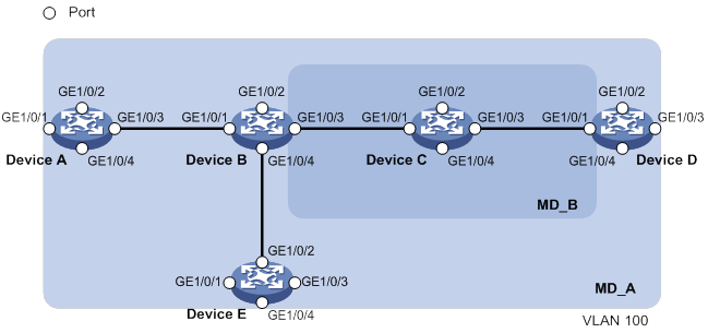
CFD exchanges messages and performs operations on a per-domain basis. By planning MDs correctly in a network, you can use CFD to rapidly locate failure points.
Maintenance association
A maintenance association (MA) is a part of an MD. You can configure multiple MAs in an MD as needed. An MA is identified by the MD name + MA name.
In an Ethernet network, an MA serves the specified VLAN or no VLAN. An MA that serves a VLAN is considered to be carrying VLAN attribute. An MA that serves no VLAN is considered to be carrying no VLAN attribute.
In an MPLS Layer 2 VPN, an MA can only serve the specified cross-connect.
An MP can receive packets sent by other MPs in the same MA. The level of an MA equals the level of the MD that the MA belongs to.
Maintenance point
An MP is configured on a port and belongs to an MA. MPs include the following types: maintenance association end points (MEPs) and maintenance association intermediate points (MIPs).
· MEP
MEPs define the boundary of the MA. Each MEP is identified by a MEP ID.
In an Ethernet network, the MA to which a MEP belongs defines the VLAN of packets sent by the MEP.
In an MPLS Layer 2 VPN, the MA to which a MEP belongs defines the cross-connect of packets sent by the MEP.
The level of a MEP equals the level of the MD to which the MEP belongs. The level of packets sent by a MEP equals the level of the MEP.
The level of a MEP determines the levels of packets that the MEP can process. A MEP forwards packets at a higher level and processes packet of its level or lower.
MEPs include inward-facing MEPs and outward-facing MEPs:
? An inward-facing MEP does not send packets to its host port. Rather, it sends packets to other ports on the device. In an Ethernet network, the packets are broadcast in the VLAN that the MA of the MEP serves. In an MPLS Layer 2 VPN, the packets are broadcast in the cross-connect to which the MEP belongs.
? An outward-facing MEP sends packets to its host port. Outward-facing MEPs are supported only in Ethernet networks.
· MIP
A MIP is internal to an MA. It cannot send CFD packets actively, but it can handle and respond to CFD packets. By cooperating with MEPs, a MIP can perform a function similar to ping and traceroute. A MIP forwards packets of a different level without any processing and only processes packet of its level.
The MA to which a MIP belongs defines the VLAN of packets that the MIP can receive.
The MIP-related configuration takes effect only in Ethernet networks.
The level of a MIP is defined by its generation rule and the MD to which the MIP belongs. MIPs are generated on each port automatically according to the following MIP generation rules:
? Default rule—If no lower-level MIP exists on an interface, a MIP is created on the current level. A MIP can be created even if no MEP is configured on the interface.
? Explicit rule—If no lower-level MIP exists and a lower-level MEP exists on an interface, a MIP is created on the current level. A MIP can be created only when a lower-level MEP is created on the interface.
If a port has no MIP, the system will check the MAs in each MD (from low to high levels), and follow the procedure as described in Figure 7 to create or not to create MIPs at the current level.
Figure 7 Procedure of creating MIPs
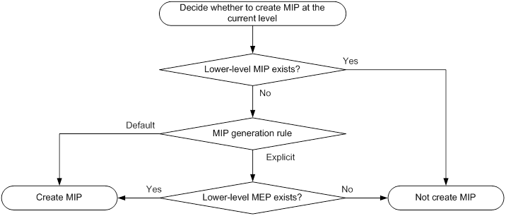
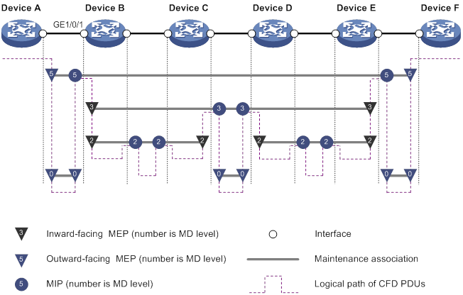
Figure 8 demonstrates a grading example of the CFD module. Four levels of MDs (0, 2, 3, and 5) are designed. The bigger the number, the higher the level and the larger the area covered. MPs are configured on the ports of Device A through Device F. GigabitEthernet 1/0/1 of Device B is configured with the following MPs:
· A level 5 MIP.
· A level 3 inward-facing MEP.
· A level 2 inward-facing MEP.
· A level 0 outward-facing MEP.
MEP list
A MEP list is a collection of local MEPs allowed to be configured and the remote MEPs to be monitored in the same MA. It lists all the MEPs configured on different devices in the same MA. The MEPs all have unique MEP IDs. When a MEP receives from a remote device a continuity check message (CCM) carrying a MEP ID not in the MEP list of the MA, it drops the message.
The local device must send CCM messages carrying the Remote Defect Indication (RDI) flag bits. Otherwise, the peer device cannot sense certain failures. When a local MEP has not learned all remote MEPs in the MEP list, the MEPs in the MA will not carry the RDI flag bits in CCMs.
CFD functions
CFD functions, which are implemented through the MPs, include:
· Continuity check (CC).
· Loopback (LB).
· Linktrace (LT).
· Alarm indication signal (AIS).
· Loss measurement (LM).
· Delay measurement (DM).
· Test (TST).
Continuity check
Connectivity faults are usually caused by device faults or configuration errors. Continuity check examines the connectivity between MEPs. This function is implemented through periodic sending of CCMs by the MEPs. A CCM sent by one MEP is intended to be received by all the other MEPs in the same MA. If a MEP fails to receive the CCMs within 3.5 times the sending interval, the link is considered as faulty and a log is generated. When multiple MEPs send CCMs at the same time, the multipoint-to-multipoint link check is achieved. CCM frames are multicast frames.
Loopback
Similar to ping at the IP layer, loopback verifies the connectivity between a source device and a target device. To implement this function, the source MEP sends loopback messages (LBMs) to the target MEP. Depending on whether the source MEP can receive a loopback reply message (LBR) from the target MEP, the link state between the two can be verified.
LBM frames are multicast and unicast frames. The device can send and receive unicast LBM frames, and can receive multicast LBM frames but cannot send multicast LBM frames. LBR frames are unicast frames.
Linktrace
Linktrace is similar to traceroute. It identifies the path between the source MEP and the target MP. The source MEP sends the linktrace messages (LTMs) to the target MP. After receiving the messages, the target MP and the MIPs that the LTM frames pass send back linktrace reply messages (LTRs) to the source MEP. Based on the reply messages, the source MEP can identify the path to the target MP. LTM frames are multicast frames and LTRs are unicast frames.
AIS
The AIS function suppresses the number of error alarms reported by MEPs. If a local MEP does not receive any CCM frames from its peer MEP within 3.5 times the CCM transmission interval, it immediately starts sending AIS frames. The AIS frames are sent periodically in the opposite direction of CCM frames. When the peer MEP receives the AIS frames, it suppresses the error alarms locally, and continues to send the AIS frames. If the local MEP receives CCM frames within 3.5 times the CCM transmission interval, it stops sending AIS frames and restores the error alarm function. AIS frames are multicast frames.
This function can be configured only in Ethernet networks.
LM
The LM function measures the frame loss in a certain direction between a pair of MEPs. The source MEP sends loss measurement messages (LMMs) to the target MEP. The target MEP responds with loss measurement replies (LMRs). The source MEP calculates the number of lost frames according to the counter values of the two consecutive LMRs (the current LMR and the previous LMR). LMMs and LMRs are unicast frames.
The LM function can be implemented in one of the following ways:
· Short-period LM—The source MEP sends a configurable number of LMMs at a configurable interval.
· Continual LM—The source MEP continually sends LMMs at a configurable interval until continual LM is administratively disabled. To view the test result, use the display cfd slm history command on the target MEP.
Continual LM can work with port collaboration. Port collaboration shuts down or blocks a port based on the continual LM result. For more information about port collaboration, see "Port collaboration."
DM
The DM function measures frame delays between two MEPs, including the following types:
· One-way frame delay measurement
The source MEP sends a one-way delay measurement (1DM) frame, which carries the transmission time, to the target MEP. When the target MEP receives the 1DM frame, it does the following:
? Records the reception time.
? Calculates and records the link transmission delay and jitter (delay variation) according to the transmission time and reception time.
1DM frames are unicast frames.
This function can be configured only in Ethernet networks.
· Two-way frame delay measurement
The source MEP sends a delay measurement message (DMM), which carries the transmission time, to the target MEP. When the target MEP receives the DMM, it responds with a delay measurement reply (DMR). The DMR carries the reception time and transmission time of the DMM and the transmission time of the DMR. When the source MEP receives the DMR, it does the following:
? Records the DMR reception time.
? Calculates the link transmission delay and jitter according to the DMR reception time and DMM transmission time.
DMM frames and DMR frames are unicast frames.
The two-way DM function can be implemented in one of the following ways:
? Short-period two-way DM—The source MEP sends a configurable number of DMMs at a configurable interval.
? Continual two-way DM—The source MEP continually sends DMMs at a configurable interval until continual two-way DM is administratively disabled. To view the test result, use the display cfd dm two-way history command on the target MEP.
Continual two-way DM can work with port collaboration. Port collaboration shuts down or blocks a port based on the continual two-way DM result. For more information about port collaboration, see "Port collaboration."
TST
The TST function tests the bit errors between two MEPs. The source MEP sends a TST frame, which carries the test pattern, such as pseudo random bit sequence (PRBS) or all-zero, to the target MEP. When the target MEP receives the TST frame, it determines the bit errors by calculating and comparing the content of the TST frame. TST frames are unicast frames.
This function can be configured only in Ethernet networks.
The TST function can be implemented in one of the following ways:
· Short-period TST—The source MEP sends a configurable number of TST frames at a configurable interval.
· Continual TST—The source MEP continually sends TST frames at a configurable interval until continual TST is administratively disabled. To view the test result, use the display cfd tst history command on the target MEP.
Continual TST can work with port collaboration. Port collaboration shuts down or blocks a port based on the continual TST result. For more information about port collaboration, see "Port collaboration."
Port collaboration
Triggering events
Port collaboration shuts down or blocks ports based on the result of link detection performed by outward-facing MEPs.
Port collaboration can be triggered by the following events:
· Continuity check expires.
· The link transmission delay in continual two-way DM reaches or exceeds the upper limit, or reaches or falls below the lower limit.
· The CCMs with the RDI flag bit set are received.
· The packet loss ratio in continual LM reaches or exceeds the upper limit, or reaches or falls below the lower limit.
· The bit error ratio in continual TST reaches or exceeds the upper limit, or reaches or falls below the lower limit.
You can specify multiple triggering events for an interface. All configured triggering events can take effect.
Triggered actions
Port collaboration takes one of the following triggered actions:
· Blocks the port by changing its link layer protocol state to DOWN (CFD). The port cannot send or receive any data packets.
· Shuts down the port by changing its physical state to CFD DOWN. The port cannot send or receive any data packets or protocol packets.
Link recovery
If a port is blocked by CFD, it can automatically come up when the link recovers, except that the block action is triggered by continual LM. To bring up the port blocked in continual LM, execute the undo cfd port-trigger slm action or cfd slm port-trigger up-delay command.
If a port is shut down by CFD, it cannot automatically come up when the link recovers. To bring up the port, you must execute the undo shutdown or undo cfd port-trigger command.
Protocols and standards
· IEEE 802.1ag, Virtual Bridged Local Area Networks Amendment 5: Connectivity Fault Management
· ITU-T Y.1731, OAM functions and mechanisms for Ethernet based networks
CFD configuration task list
For CFD to work correctly, design the network by performing the following tasks:
· Grade the MDs in the entire network, and define the boundary of each MD.
· Assign a name for each MD. Make sure that the devices in the same MD use the same MD name.
· Define the MA in each MD according to the VLAN or cross-connect you want to monitor.
· Assign a name for each MA. Make sure that the devices in the same MA in the same MD use the same MA name.
· Determine the MEP list of each MA in each MD. Make sure that devices in the same MA maintain the same MEP list.
· At the edges of MD and MA, MEPs must be designed at the device interface. MIPs can be designed on devices or interfaces that are not at the edges in Ethernet networks.
To configure CFD, perform the following tasks:
|
Tasks at a glance |
|
|
Configuring basic CFD settings: · (Required.) Enabling CFD · (Required.) Configuring service instances · (Required.) Configuring MEPs · (Required.) Configuring MIP auto-generation rules |
|
|
· (Required.) Configuring CC · (Optional.) Configuring LB · (Optional.) Configuring LT · (Optional.) Configuring AIS · (Optional.) Configuring LM · (Optional.) Configuring one-way DM · (Optional.) Configuring two-way DM · (Optional.) Configuring TST |
|
|
(Optional.) Configuring port collaboration |
Typically, an interface blocked by the spanning tree feature cannot receive or send CFD messages except in the following cases:
· The interface is configured as an outward-facing MEP.
· The interface is configured as a MIP or inward-facing MEP, which can still receive and send CFD messages except CCM messages.
For more information about the spanning tree feature, see Layer 2—LAN Switching Configuration Guide.
Configuring basic CFD settings
Enabling CFD
|
Step |
Command |
Remarks |
|
1. Enter system view. |
system-view |
N/A |
|
2. Enable CFD. |
cfd enable |
By default, CFD is disabled. |
Configuring service instances
Before configuring the MEPs and MIPs, you must first configure service instances. A service instance is a set of service access points (SAPs), and belongs to an MA in an MD.
The MD and MA define the level attribute and VLAN attribute of the messages handled by the MPs in a service instance. The MPs of the MA that carries no VLAN attribute do not belong to any VLAN.
To configure a service instance with the MD name:
|
Step |
Command |
Remarks |
|
1. Enter system view. |
system-view |
N/A |
|
2. Create an MD. |
cfd md md-name [ index index-value ] level level-value |
By default, no MDs exist. |
|
3. Create a service instance. |
cfd service-instance instance-id ma-id { icc-based ma-name | integer ma-num | string ma-name | vlan-based [ vlan-id ] } [ ma-index index-value ] md md-name [ vlan vlan-id ] |
By default, no service instance exists. |
Configuring MEPs
CFD is implemented through various operations on MEPs. As a MEP is configured on a service instance, the MD level and VLAN or cross-connect attribute of the service instance become the attribute of the MEP.
Before creating MEPs, configure the MEP list. A MEP list is a collection of local MEPs that can be configured in an MA and the remote MEPs to be monitored. You cannot create a MEP if the MEP ID is not included in the MEP list of the service instance.
You can specify an interface as the MEP for only one of the non-VLAN-specific MAs at the same level. In addition, the MEP must be outward facing.
To create a MEP for an MA that carries VLAN attribute on an Layer 3 Ethernet interface, make sure the following requirements are met:
· The device supports subinterfaces.
· The subinterfaces support VLAN termination. For more information about VLAN termination, see Layer 2—LAN Switching Configuration Guide.
To configure a MEP:
|
Step |
Command |
Remarks |
|
1. Enter system view. |
system-view |
N/A |
|
2. Configure a MEP list. |
cfd meplist mep-list service-instance instance-id |
By default, no MEP list is configured. |
|
3. Enter Layer 2 or Layer 3 Ethernet interface view or Layer 2 aggregate interface view. |
interface interface-type interface-number |
N/A |
|
4. Create a MEP. |
·
Create a MEP in Layer 2 Ethernet
interface view or Layer 2 aggregate interface view: ·
Create a MEP in Layer 3 Ethernet interface
view: |
By default, no MEPs are configured. |
Configuring MIP auto-generation rules
As functional entities in a service instance, MIPs respond to various CFD frames, such as LTM and LBM frames. You can configure MIP auto-generation rules for the system to automatically create MIPs.
The MIP-related configuration takes effect only in Ethernet networks.
Any of the following events can cause MIPs to be created or deleted after you have configured the cfd mip-rule command:
· Enabling or disabling CFD.
· Creating or deleting MEPs on a port.
· Changes occur to the VLAN attribute of an interface.
· The rule specified in the cfd mip-rule command changes.
An MA carrying no VLAN attribute is typically used to detect direct link status. The system cannot generate MIPs for such MAs.
For an MA carrying VLAN attribute, the system does not generate MIPs if the same or a higher level MEP exists on the interface.
To configure the rules for generating MIPs:
|
Step |
Command |
Remarks |
|
1. Enter system view. |
system-view |
N/A |
|
2. Configure MIP auto-generation rules. |
cfd mip-rule { default | explicit } service-instance instance-id |
By default, no rules for generating MIPs are configured, and the system does not automatically create any MIP. |
Configuring CFD functions
Configuration prerequisites
Complete basic CFD settings.
Configuring CC
Configure CC before you use the MEP ID of the remote MEP to configure other CFD functions. This restriction does not apply when you use the MAC address of the remote MEP to configure other CFD functions.
After the CC function is configured, MEPs in an MA can periodically send CCM frames to maintain connectivity. When the lifetime of a CCM frame expires, the link to the sending MEP is considered disconnected. When setting the CCM interval, use the settings described in Table 3.
Table 3 CCM interval field encoding
|
CCM interval field |
Transmission interval |
Maximum CCM lifetime |
|
1 |
10/3 milliseconds |
35/3 milliseconds |
|
2 |
10 milliseconds |
35 milliseconds |
|
3 |
100 milliseconds |
350 milliseconds |
|
4 |
1 second |
3.5 seconds |
|
5 |
10 seconds |
35 seconds |
|
6 |
60 seconds |
210 seconds |
|
7 |
600 seconds |
2100 seconds |
|
|
NOTE: The CCM messages with an interval field value of 1 to 3 are short-interval CCM messages. The CCM messages with an interval field value of 4 to 7 are long-interval CCM messages. |
Follow these guidelines when you configure CC on a MEP:
· Configure the same CCM interval field value for all MEPs in the same MA.
· After the CCM interval field is modified, the MEP that does not support hardware CC must wait for another CCM interval before sending CCMs.
· If the device cannot process short-interval CCM messages, setting the CCM interval field value to smaller than 4 might cause the CC function to operate unsteadily.
· If the device has multiple cards with auxiliary CPUs, all MEPs on the device send CCM frames through one of these cards. If the sending card is removed, another card takes over to send CCM frames. If all these cards are removed, MEPs with a short CCM interval immediately stop sending CCM frames. MEPs with a long CCM interval send CCM frames through the cards where the MEPs are created.
· The cards without auxiliary CPUs discard short-interval CCM messages to reduce impact on CPU performance. If your device does not have an auxiliary CPU, configure a long CCM interval for all MEPs as a best practice.
· Only the outward-facing MEP on a physical port supports hardware CC. The hardware CC function does not take effect on the physical port in either of the following cases:
? The physical port is added to an aggregation group.
? The MEP on the physical port is an inward-facing MEP.
To make the outward-facing MEP on the card that supports hardware CC receive CCMs, enable hardware CC on the port where the outward-facing MEP resides.
Configuring CC on a MEP in an Ethernet network
|
Step |
Command |
Remarks |
|
1. Enter system view. |
system-view |
N/A |
|
2. (Optional.) Set the CCM interval field. |
cfd cc interval interval-value service-instance instance-id |
By default, the interval field value is 4. |
|
3. Enter Layer 2 or Layer 3 Ethernet interface view or Layer 2 aggregate interface view. |
interface interface-type interface-number |
N/A |
|
4. Enable CCM sending on a MEP. |
cfd cc service-instance instance-id mep mep-id enable |
By default, CCM sending is disabled on a MEP. |
|
5. Return to system view. |
quit |
N/A |
|
6. Enter Layer 2 or Layer 3 Ethernet interface view. |
interface interface-type interface-number |
N/A |
|
7. (Optional.) Enable hardware CC on a MEP. |
cfd hardware-cc service-instance instance-id remote-mep mep-list |
By default, hardware CC is disabled on a MEP. |
Configuring CC on a MEP in an MPLS Layer 2 VPN
|
Step |
Command |
Remarks |
|
1. Enter system view. |
system-view |
N/A |
|
2. (Optional.) Set the CCM interval field. |
cfd cc interval interval-value service-instance instance-id |
By default, the interval field value is 4. |
|
3. Enter Layer 3 Ethernet subinterface view. |
interface interface-type interface-number.subnumber |
N/A |
|
4. Enable CCM sending on a MEP. |
cfd cc service-instance instance-id mep mep-id enable |
By default, CCM sending is disabled on a MEP. |
Configuring LB
The LB function can verify the link state between the local MEP and the remote MEP or MIP.
To configure LB on a MEP:
|
Task |
Command |
Remarks |
|
Enable LB. |
cfd loopback service-instance instance-id mep mep-id { target-mac mac-address | target-mep target-mep-id } [ number number ] |
Available in any view. |
Configuring LT
LT can trace the path between source and target MEPs, and can locate link faults by automatically sending LT messages. The two functions are implemented in the following way:
· Tracing path—The source MEP first sends LTM messages to the target MEP. Based on the LTR messages in response to the LTM messages, the path between the two MEPs is identified.
· LT messages automatic sending—If the source MEP fails to receive CCM frames from the target MEP within 3.5 times the transmission interval, it considers the link faulty. The source MEP then sends LTM frames, with the TTL field set to the maximum value 255, to the target MEP. Based on the returned LTRs, the fault source is located.
|
|
IMPORTANT: · In an Ethernet network, before you configure LT on a MEP in an MA carrying VLAN attribute, create the VLAN to which the MA belongs. · In an MPLS Layer 2 VPN, before you configure LT on a MEP in an MA carrying cross-connect attribute, create the cross-connect to which the MA belongs. |
To configure LT on MEPs:
|
Step |
Command |
Remarks |
|
1. Identify the path between a source MEP and a target MEP. |
cfd linktrace service-instance instance-id mep mep-id { target-mac mac-address | target-mep target-mep-id } [ ttl ttl-value ] [ hw-only ] |
Available in any view. |
|
2. Enter system view. |
system-view |
N/A |
|
3. Enable LT messages automatic sending. |
cfd linktrace auto-detection [ size size-value ] |
By default, LT messages automatic sending is disabled. |
Configuring AIS
The AIS function suppresses the number of error alarms reported by MEPs.
This function can be configured only in Ethernet networks.
To make a MEP in the service instance send AIS frames, set the AIS frame transmission level to be higher than the MD level of the MEP.
Enable AIS and configure a correct AIS frame transmission level on the target MEP, so the target MEP can do the following:
· Suppress the error alarms.
· Send the AIS frame to the MD of a higher level.
If you enable AIS but do not configure a correct AIS frame transmission level, the target MEP can suppress the error alarms, but cannot send the AIS frames.
To configure AIS:
|
Step |
Command |
Remarks |
|
1. Enter system view. |
system-view |
N/A |
|
2. Enable AIS. |
cfd ais enable |
By default, AIS is disabled. |
|
3. Configure the AIS frame transmission level. |
cfd ais level level-value service-instance instance-id |
By default, the AIS frame transmission level is not configured. |
|
4. Configure the AIS frame transmission interval. |
cfd ais period period-value service-instance instance-id |
By default, the AIS frame transmission interval is 1 second. |
Configuring LM
About LM
The LM function measures frame loss between MEPs. Frame loss statistics include the number of lost frames, the frame loss ratio, and the average number of lost frames for the source and target MEPs.
Configuring short-period LM in an Ethernet network
|
Task |
Command |
Remarks |
|
Configure short-period LM. |
cfd slm service-instance instance-id mep mep-id { target-mac mac-address | target-mep target-mep-id } [ dot1p dot1p-value ] [ number number ] [ interval interval ] |
Available in any view. |
Configuring continual LM in an Ethernet network
Continual LM is not supported in an MPLS Layer 2 VPN.
To configure continual LM in an Ethernet network:
|
Step |
Command |
Remarks |
|
1. Enter system view. |
system-view |
N/A |
|
2. Configure continual LM. |
cfd slm continual service-instance instance-id mep mep-id { target-mac mac-address | target-mep target-mep-id } [ dot1p dot1p-value ] [ interval interval ] |
By default, continual LM is not configured. |
Configuring short-period LM in an MPLS Layer 2 VPN
|
Task |
Command |
Remarks |
|
Configure short-period LM. |
cfd slm service-instance instance-id mep mep-id { target-mac mac-address | target-mep target-mep-id } [ dot1p dot1p-value ] [ number number ] [ interval interval ] |
Available in any view. |
Configuring one-way DM
The one-way DM function measures the one-way frame delay between two MEPs, and monitors and manages the link transmission performance.
This function can be configured only in Ethernet networks.
One-way DM requires that the time setting at the source MEP and the target MEP be the same. For the purpose of frame delay variation measurement, the requirement can be relaxed.
To view the test result, use the display cfd dm one-way history command on the target MEP.
To configure one-way DM:
|
Task |
Command |
Remarks |
|
Configure one-way DM. |
cfd dm one-way service-instance instance-id mep mep-id { target-mac mac-address | target-mep target-mep-id } [ number number ] |
Available in any view. |
Configuring two-way DM
About two-way DM
The two-way DM function measures the two-way frame delay, average two-way frame delay, and two-way frame delay variation between two MEPs. It also monitors and manages the link transmission performance.
Configuring short-period two-way DM
|
Task |
Command |
Remarks |
|
Configure short-period two-way DM. |
cfd dm two-way service-instance instance-id mep mep-id { target-mac mac-address | target-mep target-mep-id } [ dot1p dot1p-value ] [ number number ] [ interval interval ] |
Available in any view. |
Configuring continual two-way DM
This function can be configured only in Ethernet networks.
To configure continual two-way DM:
|
Step |
Command |
Remarks |
|
1. Enter system view. |
system-view |
N/A |
|
2. Configure continual two-way DM. |
cfd dm two-way continual service-instance instance-id mep mep-id { target-mac mac-address | target-mep target-mep-id } [ dot1p dot1p-value ] [ interval interval ] |
By default, continual two-way DM is not configured. |
Configuring TST
About TST
The TST function detects bit errors on a link, and monitors and manages the link transmission performance.
Restrictions and guidelines
This function can be configured only in Ethernet networks.
Configuring short-period TST
|
Task |
Command |
Remarks |
|
Configure short-period TST. |
cfd tst service-instance instance-id mep mep-id { target-mac mac-address | target-mep target-mep-id } [ number number ] [ length-of-test length ] [ pattern-of-test { all-zero | prbs } [ with-crc ] ] |
Available in any view. |
Configuring continual TST
|
Step |
Command |
Remarks |
|
1. Enter system view. |
system-view |
N/A |
|
2. Configure continual TST. |
cfd tst continual service-instance instance-id mep mep-id { target-mac mac-address | target-mep target-mep-id } [ length-of-test length ] [ pattern-of-test { all-zero | prbs } [ with-crc ] ] [ interval interval ] |
By default, continual TST is not configured. |
Configuring port collaboration
Restrictions and guidelines
This function can be configured only in Ethernet networks.
This function takes effect only on the ports with outward-facing MEPs configured.
Configuring port collaboration for CC
|
Step |
Command |
|
1. Enter system view. |
system-view |
|
2. Enter Layer 2/Layer 3 Ethernet interface view or Layer 2 aggregate interface view. |
interface interface-type interface-number |
|
3. Configure port collaboration for CC. |
cfd port-trigger cc-expire action { block | shutdown } |
Configuring port collaboration for continual two-way DM
|
Step |
Command |
Remarks |
|
1. Enter system view. |
system-view |
N/A |
|
2. Enter Layer 2/Layer 3 Ethernet interface view or Layer 2 aggregate interface view. |
interface interface-type interface-number |
N/A |
|
3. Configure port collaboration for continual two-way DM. |
cfd port-trigger dm action { block | shutdown } |
N/A |
|
4. Return to system view. |
quit |
N/A |
|
5. Configure the lower limit and upper limit for continual two-way DM. |
cfd dm two-way threshold service-instance instance-id mep mep-id { lower-limit lower-limit | upper-limit upper-limit } * |
By default, the lower limit and upper limit for continual two-way DM are 0 and 4294967295 microseconds, respectively. |
Configuring port collaboration for RDI
|
Step |
Command |
|
1. Enter system view. |
system-view |
|
2. Enter Layer 2/Layer 3 Ethernet interface view or Layer 2 aggregate interface view. |
interface interface-type interface-number |
|
3. Configure port collaboration for RDI. |
cfd port-trigger rdi action { block | shutdown } |
Configuring port collaboration for continual LM
|
Step |
Command |
Remarks |
|
1. Enter system view. |
system-view |
N/A |
|
2. Enter Layer 2/Layer 3 Ethernet interface view or Layer 2 aggregate interface view. |
interface interface-type interface-number |
N/A |
|
3. Configure port collaboration for continual LM. |
cfd port-trigger slm action { block | shutdown } |
N/A |
|
4. Return to system view. |
quit |
N/A |
|
5. Configure the lower limit and upper limit for continual LM. |
cfd slm { far-end | near-end } threshold service-instance instance-id mep mep-id { lower-limit lower-limit | upper-limit upper-limit } * |
By default, the lower limit and upper limit for continual LM are 0 and 100%, respectively. |
|
6. Enable automatic port recovery for continual LM and set the delay time for automatic recovery. |
cfd slm port-trigger up-delay delay |
By default, the undo cfd port-trigger slm action command is required to bring up a port blocked in continual LM. For devices that support this command, see High Availability Command Reference. |
Configuring port collaboration for continual TST
|
Step |
Command |
Remarks |
|
1. Enter system view. |
system-view |
N/A |
|
2. Enter Layer 2/Layer 3 Ethernet interface view or Layer 2 aggregate interface view. |
interface interface-type interface-number |
N/A |
|
3. Configure port collaboration for continual TST. |
cfd port-trigger tst action { block | shutdown } |
N/A |
|
4. Return to system view. |
quit |
N/A |
|
5. Configure the lower limit and upper limit for continual TST. |
cfd tst threshold service-instance instance-id mep mep-id { lower-limit lower-limit | upper-limit upper-limit } * |
By default, the lower limit and upper limit for continual TST are 0 and 100%, respectively. |
Displaying and maintaining CFD
Execute display commands in any view and reset commands in user view.
|
Task |
Command |
|
Display the AIS configuration and information on the specified MEP. |
display cfd ais [ service-instance instance-id [ mep mep-id ] ] |
|
Display the one-way DM result on the specified MEP. |
display cfd dm one-way history [ service-instance instance-id [ mep mep-id ] ] |
|
Display LTR information received by a MEP. |
display cfd linktrace-reply [ service-instance instance-id [ mep mep-id ] ] |
|
Display the content of the LTR messages received as responses to the automatically sent LTMs. |
display cfd linktrace-reply auto-detection [ size size-value ] |
|
Display MD configuration information. |
display cfd md |
|
Display the attribute and running information of the MEPs. |
display cfd mep mep-id service-instance instance-id |
|
Display MEP lists in a service instance. |
display cfd meplist [ service-instance instance-id ] |
|
Display MP information. |
display cfd mp [ interface interface-type interface-number ] |
|
Display information about a remote MEP. |
display cfd remote-mep service-instance instance-id mep mep-id |
|
Display service instance configuration information. |
display cfd service-instance [ instance-id ] |
|
Display CFD status. |
display cfd status |
|
Display the TST result on the specified MEP. |
display cfd tst [ service-instance instance-id [ mep mep-id ] ] |
|
Clear the one-way DM result on the specified MEP. |
reset cfd dm one-way history [ service-instance instance-id [ mep mep-id ] ] |
|
Clear the TST result on the specified MEP. |
reset cfd tst [ service-instance instance-id [ mep mep-id ] ] |
Configuring BFD
Overview
Bidirectional forwarding detection (BFD) provides a general-purpose, standard, medium- and protocol-independent fast failure detection mechanism. It can detect and monitor the connectivity of links in IP to detect communication failures quickly so that measures can be taken to ensure service continuity and enhance network availability.
BFD can uniformly and quickly detect the failures of the bidirectional forwarding paths between two devices for upper-layer protocols such as routing protocols and MPLS. The hello mechanism used by upper-layer protocols needs seconds to detect a link failure, while BFD can provide detection measured in milliseconds.
BFD can be used for single-hop and multihop detections.
· Single-hop detection—Detects the IP connectivity between two directly connected systems.
· Multihop detection—Detects any of the paths between two systems. These paths have multiple hops, and might overlap.
BFD session establishment and termination
Establishing a BFD session
BFD does not provide any neighbor discovery mechanisms. The upper protocol notifies BFD of the routers to which it needs to establish sessions.
A BFD session is established as follows:
1. A protocol sends Hello messages to discover neighbors and establish neighborships.
2. After establishing a neighborship, the protocol notifies BFD of the neighbor information, including destination and source addresses.
3. BFD uses the information to establish a BFD session.
Terminating a BFD session
When BFD detects a link failure, it performs the following tasks:
1. BFD clears the neighbor session.
2. BFD notifies the protocol of the failure.
3. The protocol terminates the neighborship on the link.
4. If a backup link is available, the protocol will use it for communication.
BFD session modes and operating modes
BFD sessions use the following types of packets:
· Echo packets—Encapsulated into UDP packets with port number 3785.
· Control packets—Encapsulated into UDP packets with port number 3784 for single-hop detection or port number 4784 for multihop detection.
Echo packet mode
The local end of the link sends echo packets to establish BFD sessions and monitor link status. The peer end does not establish BFD sessions and only forwards the packets back to the originating end.
In echo packet mode, BFD supports only single-hop detection and the BFD session is independent of the operating mode.
Control packet mode
Both ends of the link exchange BFD control packets to monitor link status.
Before a BFD session is established, BFD has two operating modes—active and passive.
· Active mode—BFD actively sends BFD control packets regardless of whether any BFD control packet is received from the peer.
· Passive mode—BFD does not send control packets until a BFD control packet is received from the peer.
At least one end must operate in active mode for a BFD session to be established.
After a BFD session is established, the two ends can operate in the following BFD operating modes:
· Asynchronous mode—The device periodically sends BFD control packets. The device considers that the session is down if it does not receive any BFD control packets within a specific interval.
· Demand mode—The device periodically sends BFD control packets. If the peer end is operating in Asynchronous mode (default), the peer end stops sending BFD control packets. If the peer end is operating in Demand mode, both ends stop sending BFD control packets. When the connectivity to another system needs to be verified explicitly, a system sends several BFD control packets with the Poll (P) bit set at the negotiated transmit interval. If no response is received within the detection interval, the session is considered down. If the connectivity is found to be up, no more BFD control packets are sent until the next command is issued.
In addition, both ends of the link can exchange BFD control packets to establish and maintain BFD sessions, and one end of the link sends echo packets to monitor link status.
Supported features
· Static routing. For more information, see Layer 3—IP Routing Configuration Guide.
· IPv6 static routing. For more information, see Layer 3—IP Routing Configuration Guide.
· RIP. For more information, see Layer 3—IP Routing Configuration Guide.
· OSPF. For more information, see Layer 3—IP Routing Configuration Guide.
· OSPFv3. For more information, see Layer 3—IP Routing Configuration Guide.
· IS-IS. For more information, see Layer 3—IP Routing Configuration Guide.
· IPv6 IS-IS. For more information, see Layer 3—IP Routing Configuration Guide.
· BGP. For more information, see Layer 3—IP Routing Configuration Guide.
· IPv6 BGP. For more information, see Layer 3—IP Routing Configuration Guide.
· PIM. For more information, see IP Multicast Configuration Guide.
· IPv6 PIM. For more information, see IP Multicast Configuration Guide.
· RSVP. For more information, see MPLS Configuration Guide.
· MPLS. For more information, see MPLS Configuration Guide.
· Track. For more information, see "Configuring Track."
· IP fast reroute (FRR). IP FRR is supported by BGP, OSPF, RIP, IS-IS and static routing. For more information, see Layer 3—IP Routing Configuration Guide.
· MPLS L3VPN FRR. For more information, see MPLS Configuration Guide.
· Ethernet link aggregation. For more information, see Layer 2—LAN Switching Configuration Guide.
Protocols and standards
· RFC 5880, Bidirectional Forwarding Detection (BFD)
· RFC 5881, Bidirectional Forwarding Detection (BFD) for IPv4 and IPv6 (Single Hop)
· RFC 5882, Generic Application of Bidirectional Forwarding Detection (BFD)
· RFC 5883, Bidirectional Forwarding Detection (BFD) for Multihop Paths
· RFC 5884, Bidirectional Forwarding Detection (BFD) for MPLS Label Switched Paths (LSPs)
· RFC 5885, Bidirectional Forwarding Detection (BFD) for the Pseudowire Virtual Circuit Connectivity Verification (VCCV)
· RFC 7130, Bidirectional Forwarding Detection (BFD) on Link Aggregation Group (LAG) Interfaces
Configuring BFD basic functions
Before configuring BFD basic functions, configure the network layer addresses of the interfaces so that adjacent nodes are reachable to each other at the network layer.
After a BFD session is established, the two ends negotiate BFD parameters, including minimum sending interval, minimum receiving interval, initialization mode, and packet authentication, by exchanging negotiation packets. They use the negotiated parameters without affecting the session status.
BFD session flapping might occur on an aggregate interface with member ports on different cards. When the card that receives and sends BFD packets is removed or restarted, the backup card might not immediately take over. For example, the backup card will not take over when the card has a short detection time or a large number of BFD sessions.
By default, the device runs BFD version 1 and is compatible with BFD version 0. You cannot change the BFD version to 0 through commands. When the peer device runs BFD version 0, the local device automatically switches to BFD version 0.
Configuring echo packet mode
|
|
CAUTION: To avoid echo packet loss, do not configure the echo packet mode on a device with uRPF enabled. For more information about uRPF, see Security Configuration Guide. |
To configure echo packet mode:
|
Step |
Command |
Remarks |
|
1. Enter system view. |
system-view |
N/A |
|
2. Configure the source IP address of echo packets. |
·
Configure the source IP address of echo
packets: ·
Configure the source IPv6 address of echo
packets: |
By default, no source IP address is configured for echo packets. The source IP address cannot be on the same network segment as any local interface's IP address. Otherwise, a large number of ICMP redirect packets might be sent from the peer, resulting in link congestion. The source IPv6 address of echo packets can only be a global unicast address. |
|
3. Enter interface view. |
interface interface-type interface-number |
N/A |
|
4. (Optional.) Set the minimum interval for receiving BFD echo packets. |
bfd min-echo-receive-interval interval |
By default, the minimum interval for receiving BFD echo packets is 1000 milliseconds. |
|
5. (Optional.) Set the single-hop detection time multiplier. |
bfd detect-multiplier value |
The default setting is 5. |
Configuring control packet mode
To configure control packet mode for single-hop detection:
|
Step |
Command |
Remarks |
|
1. Enter system view. |
system-view |
N/A |
|
2. Specify the mode for establishing a BFD session. |
bfd session init-mode { active | passive } |
By default, active is specified. BFD version 0 does not support this command. The configuration does not take effect. |
|
3. Enter interface view. |
interface interface-type interface-number |
N/A |
|
4. Configure the authentication mode for single-hop control packets. |
bfd authentication-mode { m-md5 | m-sha1 | md5 | sha1 | simple } key-id { cipher cipher-string | plain plain-string } |
By default, single-hop BFD packets are not authenticated. BFD version 0 does not support this command. The configuration does not take effect. |
|
5. Enable the Demand BFD session mode. |
bfd demand enable |
By default, the BFD session is in Asynchronous mode. BFD version 0 does not support this command. The configuration does not take effect. |
|
6. Enable the echo packet mode. |
bfd echo [ receive | send ] enable |
By default, the echo packet mode is disabled. BFD version 0 does not support this command. The configuration does not take effect. Configure this command for BFD sessions in which control packets are sent. When you enable the echo packet mode for such a session in up state, BFD periodically sends echo packets to detect link connectivity and decrease control packet receive rate. |
|
7. Set the minimum interval for transmitting single-hop BFD control packets. |
bfd min-transmit-interval interval |
By default, the minimum interval for transmitting single-hop BFD control packets is 1000 milliseconds. |
|
8. Set the minimum interval for receiving single-hop BFD control packets. |
bfd min-receive-interval interval |
By default, the minimum interval for receiving single-hop BFD control packets is 1000 milliseconds. |
|
9. Set the single-hop detection time multiplier. |
bfd detect-multiplier value |
The default setting is 5. |
|
10. Create a BFD session for detecting the local interface state. |
bfd detect-interface source-ip ip-address |
By default, no BFD session is created for detecting the local interface state. |
|
11. Return to system view. |
quit |
N/A |
|
12. (Optional.) Set the delay timer for BFD to notify upper-layer protocols of session establishment failures. |
bfd init-fail-timer seconds |
By default, BFD does not notify upper-layer protocols of session establishment failures. |
To configure control packet mode for multihop detection:
|
Step |
Command |
Remarks |
|
1. Enter system view. |
system-view |
N/A |
|
2. Specify the mode for establishing a BFD session. |
bfd session init-mode { active | passive } |
By default, active is specified. BFD version 0 does not support this command. The configuration does not take effect. |
|
3. Configure the authentication mode for multihop BFD control packets. |
bfd multi-hop authentication-mode { m-md5 | m-sha1 | md5 | sha1 | simple } key-id { cipher cipher-string | plain plain-string } |
By default, no authentication is performed. BFD version 0 does not support this command. The configuration does not take effect. |
|
4. Configure the destination port number for multihop BFD control packets. |
bfd multi-hop destination-port port-number |
The default setting is 4784. |
|
5. Set the multihop detection time multiplier. |
bfd multi-hop detect-multiplier value |
The default setting is 5. |
|
6. Set the minimum interval for receiving multihop BFD control packets. |
bfd multi-hop min-receive-interval interval |
By default, the minimum interval for receiving multihop BFD control packets is 1000 milliseconds. |
|
7. Set the minimum interval for transmitting multihop BFD control packets. |
bfd multi-hop min-transmit-interval interval |
By default, the minimum interval for transmitting multihop BFD control packets is 1000 milliseconds. |
|
8. (Optional.) Set the delay timer for BFD to notify upper-layer protocols of session establishment failures. |
bfd init-fail-timer seconds |
By default, BFD does not notify upper-layer protocols of session establishment failures. |
Configuring a BFD template
Perform this task to specify BFD parameters in a template for sessions without next hops. You can configure BFD parameters for LSPs and PWs through a BFD template.
To configure a BFD template:
|
Step |
Command |
Remarks |
|
1. Enter system view. |
system-view |
N/A |
|
2. Create a BFD template and enter BFD template view. |
bfd template template-name |
By default, no BFD templates exist. |
|
3. Configure the authentication mode for BFD control packets. |
bfd authentication-mode { m-md5 | m-sha1 | md5 | sha1 | simple } key-id { cipher cipher-string | plain plain-string } |
By default, no authentication is performed. BFD version 0 does not support this command. The configuration does not take effect. |
|
4. Set the detection time multiplier. |
bfd detect-multiplier value |
The default setting is 5. |
|
5. Set the minimum interval for receiving BFD control packets. |
bfd min-receive-interval interval |
By default, the minimum interval for receiving BFD control packets is 1000 milliseconds. |
|
6. Set the minimum interval for transmitting BFD control packets. |
bfd min-transmit-interval interval |
By default, the minimum interval for transmitting BFD control packets is 1000 milliseconds. |
Enabling SNMP notifications for BFD
To report critical BFD events to an NMS, enable SNMP notifications for BFD. For BFD event notifications to be sent correctly, you must also configure SNMP as described in Network Management and Monitoring Configuration Guide.
To enable SNMP notifications for BFD:
|
Command |
Remarks |
|
|
1. Enter system view. |
system-view |
N/A |
|
2. Enable SNMP notifications for BFD. |
By default, SNMP notifications are enabled for BFD. |
Displaying and maintaining BFD
Execute the display command in any view and the reset command in user view.
|
Task |
Command |
|
Display BFD session information. |
display bfd session [ discriminator value | verbose ] |
|
Clear BFD session statistics. |
reset bfd session statistics |
Configuring Track
Overview
The Track module works between application modules and detection modules, as shown in Figure 9. It shields the differences between various detection modules from application modules.
Collaboration is enabled when you associate the Track module with a detection module and an application module, and it operates as follows:
1. The detection module probes specific objects such as interface status, link status, network reachability, and network performance, and informs the Track module of detection results.
2. The Track module sends the detection results to the application module.
3. When notified of changes for the tracked object, the application modules can react to avoid communication interruption and network performance degradation.
Figure 9 Collaboration through the Track module
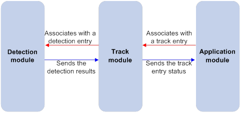
Collaboration fundamentals
The Track module collaborates with detection modules and application modules.
Collaboration between the Track module and a detection module
The detection module sends the detection result of the tracked object to the Track module. The Track module changes the status of the track entry as follows:
· If the tracked object operates correctly, the state of the track entry is Positive. For example, the track entry state is Positive in one of the following conditions:
? The target interface is up.
? The target network is reachable.
· If the tracked object does not operate correctly, the state of the track entry is Negative. For example, the track entry state is Negative in one of the following conditions:
? The target interface is down.
? The target network is unreachable.
· If the detection result is invalid, the state of the track entry is NotReady. For example, the track entry state is NotReady if its associated NQA operation does not exist.
The following detection modules can be associated with the Track module:
· NQA.
· BFD.
· Interface management.
· Route management.
You can associate a track entry with an object of a detection module, such as the state of an interface or reachability of an IP route. The state of the track entry is determined by the state of the tracked object.
You can also associate a track entry with a list of objects called a tracked list. The state of a tracked list is determined by the states of all objects in the list. The following types of tracked lists are supported:
· Boolean AND list—The state of a Boolean AND list is determined by the states of the tracked objects using the Boolean AND operation.
· Boolean OR list—The state of a Boolean OR list is determined by the states of the tracked objects using the Boolean OR operation.
· Percentage threshold list—The state of a percentage threshold list is determined by comparing the percentage of Positive objects in the list with the percentage thresholds configured for the list.
· Weight threshold list—The state of a weight threshold list is determined by comparing the weight of Positive objects in the list with the weight thresholds configured for the list.
Collaboration between the Track module and an application module
The following application modules can be associated with the Track module:
· VRRP.
· Static routing.
· PBR.
· Interface backup.
· VPLS.
· MPLS L2VPN.
· EAA.
· VXLAN.
When configuring a track entry for an application module, you can set a notification delay to avoid immediate notification of status changes.
When the delay is not configured and the route convergence is slower than the link state change notification, communication failures occur. For example, when the master in a VRRP group detects an uplink interface failure through Track, Track immediately notifies the master to decrease its priority. A backup with a higher priority then preempts as the new master. When the failed uplink interface recovers, the Track module immediately notifies the original master to restore its priority. If the uplink route has not recovered, forwarding failure will occur.
Collaboration application example
The following is an example of collaboration between NQA, Track, and static routing.
Configure a static route with next hop 192.168.0.88 on the device. If the next hop is reachable, the static route is valid. If the next hop becomes unreachable, the static route is invalid. For this purpose, configure NQA-Track-static routing collaboration as follows:
1. Create an NQA operation to monitor the accessibility of IP address 192.168.0.88.
2. Create a track entry and associate it with the NQA operation.
? When next hop 192.168.0.88 is reachable, NQA sends the result to the Track module. The Track module sets the track entry to Positive state.
? When the next hop becomes unreachable, NQA sends the result to the Track module. The Track module sets the track entry to Negative state.
3. Associate the track entry with the static route.
? When the track entry is in Positive state, the static routing module considers the static route to be valid.
? When the track entry is in Negative state, the static routing module considers the static route to be invalid.
Track configuration task list
To implement the collaboration function, establish associations between the Track module and detection modules, and between the Track module and application modules.
To configure the Track module, perform the following tasks:
|
Tasks at a glance |
Remarks |
|
Associating Track with a detection module object: |
Perform a minimum of one task. |
|
Associating Track with a tracked list: · Associating Track with a Boolean list |
|
|
Associating the Track module with an application module: · Associating Track with static routing · Associating Track with interface backup |
Perform a minimum of one task. |
Associating Track with a detection module object
Associating Track with NQA
NQA supports multiple operation types to analyze network performance and service quality. For example, an NQA operation can periodically detect whether a destination is reachable, or whether a TCP connection can be established.
An NQA operation operates as follows when it is associated with a track entry:
· If the consecutive failures reach the specified threshold, the NQA module notifies the Track module that the tracked object has malfunctioned. The Track module then sets the track entry to Negative state.
· If the specified threshold is not reached, the NQA module notifies the Track module that the tracked object is operating correctly. The Track module then sets the track entry to Positive state.
For more information about NQA, see Network Management and Monitoring Configuration Guide.
To associate Track with NQA:
|
Step |
Command |
Remarks |
|
1. Enter system view. |
system-view |
N/A |
|
2. Create a track entry, associate it with an NQA reaction entry, and enter its view. |
track track-entry-number nqa entry admin-name operation-tag reaction item-number |
By default, no track entries exist. If the specified NQA operation or the reaction entry in the track entry does not exist, the status of the track entry is NotReady. |
|
3. (Optional.) Set the delay for notifying the application module of track entry state changes. |
delay { negative negative-time | positive positive-time } * |
By default, the Track module notifies the application module immediately when the track entry state changes. |
Associating Track with BFD
BFD supports the control packet mode and echo packet mode. A track entry can be associated only with the echo-mode BFD session. For more information about BFD, see "Configuring BFD."
The associated Track and BFD operate as follows:
· If the BFD detects that the link fails, it informs the Track module of the link failure. The Track module sets the track entry to Negative state.
· If the BFD detects that the link is operating correctly, the Track module sets the track entry to Positive state.
Before you associate Track with BFD, configure the source IP address of BFD echo packets. For more information, see "Configuring BFD."
To associate Track with BFD:
|
Step |
Command |
Remarks |
|
1. Enter system view. |
system-view |
N/A |
|
2. Create a track entry, associate it with a BFD session, and enter its view. |
track track-entry-number bfd echo interface interface-type interface-number remote ip remote-ip-address local ip local-ip-address |
By default, no track entries exist. Do not configure the virtual IP address of a VRRP group as the local or remote address of a BFD session. |
|
3. (Optional.) Set the delay for notifying the application module of track entry state changes. |
delay { negative negative-time | positive positive-time } * |
By default, the Track module notifies the application module immediately when the track entry state changes. |
Associating Track with interface management
The interface management module monitors the physical status, link status, or network-layer protocol status of interfaces. The associated Track and interface management operate as follows:
· When the physical, link, or network-layer protocol status of the interface changes to up, the interface management module informs the Track module of the change. The Track module sets the track entry to Positive state.
· When the physical, link, or network-layer protocol status of the interface changes to down, the interface management module informs the Track module of the change. The Track module sets the track entry to Negative state.
To associate Track with interface management:
|
Step |
Command |
Remarks |
|
1. Enter system view. |
system-view |
N/A |
|
2. Create a track entry, associate it with an interface, and enter its view. |
·
Create a track entry to monitor the link
status of an interface: ·
Create a track entry to monitor the physical
status of an interface: ·
Create a track entry to monitor the network layer
protocol status of an interface: |
By default, no track entries exist. |
|
3. (Optional.) Set the delay for notifying the application module of track entry state changes. |
delay { negative negative-time | positive positive-time } * |
By default, the Track module notifies the application module immediately when the track entry state changes. |
Associating Track with route management
The route management module monitors route entry changes in the routing table. The associated Track and route management operate as follows:
· When a monitored route entry is found in the routing table, the route management module informs the Track module. The Track module sets the track entry to Positive state.
· When a monitored route entry is removed from the routing table, the route management module informs the Track module of the change. The Track module sets the track entry to Negative state.
To associate Track with route management:
|
Step |
Command |
Remarks |
|
1. Enter system view. |
system-view |
N/A |
|
2. Create a track entry, associate it with an IP route, and enter its view. |
track track-entry-number ip route [ vpn-instance vpn-instance-name ] ip-address { mask-length | mask } reachability |
By default, no track entries exist. |
|
3. (Optional.) Set the delay for notifying the application module of track entry state changes. |
delay { negative negative-time | positive positive-time } * |
By default, the Track module notifies the application module immediately when the track entry state changes. |
Associating Track with a tracked list
Associating Track with a Boolean list
About Boolean list
A Boolean list is a list of tracked objects based on a Boolean logic. It can be further divided into the following types:
· Boolean AND list—A Boolean AND list is set to the Positive state only when all objects are in Positive state. If one or more objects are in Negative state, the tracked list is set to the Negative state.
· Boolean OR list—A Boolean OR list is set to the Positive state if any object is in Positive state. If all objects are in Negative state, the tracked list is set to the Negative state.
Procedure
To associate Track with a Boolean list:
|
Step |
Command |
Remark |
|
1. Enter system view. |
system-view |
N/A |
|
2. Create a track entry. |
Create a track entry before you add it as a tracked object to a tracked list. A minimum of one track entry must be created. |
|
|
3. Create a Boolean tracked list and enter its view. |
track track-entry-number list boolean { and | or } |
By default, no tracked lists exist. |
|
4. Add the track entry as an object to the tracked list. |
object track-entry-number [ not ] |
By default, a tracked list does not contain any objects. Repeat this step to add all interested objects to the tracked list. |
|
5. (Optional.) Set the delay for notifying the application module of tracked list state changes. |
delay { negative negative-time | positive positive-time } * |
By default, the Track module notifies the application module immediately when the tracked list state changes. |
Associating Track with a percentage threshold list
About percentage threshold list
A percentage threshold list uses a percentage threshold to measure the state of the list.
· If the percentage of Positive objects is equal to or above the negative state threshold, the list is set to the Positive state.
· If the percentage of Positive objects is equal to or below the negative state threshold, the list is set to the Negative state.
· The state of a percentage threshold list remains unchanged if the percentage of Positive objects is below the positive state threshold and above the negative state threshold.
Procedure
To associate Track with a percentage threshold list:
|
Task |
Command |
Remark |
|
1. Enter system view. |
system-view |
N/A |
|
2. Create a track entry. |
Create a track entry before you add it as an tracked object to a tracked list. A minimum of one track entry must be created. |
|
|
3. Create a percentage threshold list and enter its view. |
track track-entry-number list threshold percentage |
By default, no tracked lists exist. |
|
4. Add the track entry as an object to the tracked list. |
object track-entry-id |
By default, a tracked list does not contain any objects. Repeat this step to add all interested objects to the tracked list. |
|
5. Configure the threshold values used to determine the state of the percentage threshold list. |
threshold percentage { negative negative-threshold | positive positive-threshold } * |
By default, the negative state threshold is 0% and the positive state threshold is 1%. |
|
6. (Optional.) Set the delay for notifying the application module of tracked list state changes. |
delay { negative negative-time | positive positive-time } * |
By default, the Track module notifies the application module immediately when the tracked list state changes. |
Associating Track with a weight threshold list
About weight threshold list
A weight threshold list uses a weight threshold to measure the state of the list.
· If the total weight of Positive objects is equal to or above the positive state threshold, the list is set to the Positive state.
· If the total weight of Positive objects is equal to or below the negative state threshold, the list is set to the Negative state.
· The state of a weight threshold list remains unchanged if the total weight of Positive objects is below the positive state threshold and above the negative state threshold.
Procedure
To associate Track with a weight threshold list:
|
Task |
Command |
Remark |
|
1. Enter system view. |
system-view |
N/A |
|
2. Create a track entry. |
Create a track entry before you add it as an tracked object to a tracked list. A minimum of one track entry must be created. |
|
|
3. Create a weight threshold list and enter its view. |
track track-entry-number list threshold weight |
By default, no tracked lists exist. |
|
4. Add the track entry as an object to the tracked list. |
object track-entry-id [ weight weight ] |
By default, a tracked list does not contain any objects. Repeat this step to add all interested objects to the tracked list. |
|
5. Configure the threshold values used to determine the state of the weight threshold list. |
threshold weight { negative negative-threshold | positive positive-threshold } * |
By default, the negative state threshold is 0 and the positive state threshold is 1. |
|
6. (Optional.) Set the delay for notifying the application module of tracked list state changes. |
delay { negative negative-time | positive positive-time } * |
By default, the Track module notifies the application module immediately when the tracked list state changes. |
Associating the Track module with an application module
Before you associate the Track module with an application module, make sure the associated track entry has been created.
Associating Track with VRRP
When VRRP is operating in standard mode or load balancing mode, associate the Track module with the VRRP group to implement the following actions:
· Change the priority of a router according to the status of the uplink. If a fault occurs on the uplink of the router, the VRRP group is not aware of the uplink failure. If the router is the master, hosts in the LAN cannot access the external network. To resolve this problem, configure a detection module-Track-VRRP collaboration. The detection module monitors the status of the uplink of the router and notifies the Track module of the detection result.
When the uplink fails, the detection module notifies the Track module to change the status of the monitored track entry to Negative. The priority of the master decreases by a user-specified value. A router with a higher priority in the VRRP group becomes the master.
· Monitor the master on a backup. If a fault occurs on the master, the backup operating in switchover mode will switch to the master immediately to maintain normal communication.
When VRRP is operating in load balancing mode, associate the Track module with the VRRP VF to implement the following functions:
· Change the priority of the AVF according to its uplink state. When the uplink of the AVF fails, the track entry changes to Negative state. The weight of the AVF decreases by a user-specified value. The VF with a higher priority becomes the new AVF to forward packets.
· Monitor the AVF status from the LVF. When the AVF fails, the LVF that is operating in switchover mode becomes the new AVF to ensure continuous forwarding.
When you associate Track with VRRP, follow these restrictions and guidelines:
· VRRP tracking does not take effect on an IP address owner. The configuration takes effect when the router does not act as the IP address owner.
An IP address owner is the router with its interface IP address used as the virtual IP address of the VRRP group.
· When the status of the track entry changes from Negative to Positive or NotReady, the associated router or VF restores its priority automatically.
Associating Track with a VRRP group
|
Step |
Command |
Remarks |
|
1. Enter system view. |
system-view |
N/A |
|
2. Enter interface view. |
interface interface-type interface-number |
N/A |
|
3. Associate a track entry with a VRRP group. |
vrrp [ ipv6 ] vrid virtual-router-id track track-entry-number { forwarder-switchover member-ip ip-address | priority reduced [ priority-reduced ] | switchover | weight reduced [ weight-reduced ] } |
By default, no track entry is specified for a VRRP group. This command is supported when VRRP is operating in both standard mode and load balancing mode. |
Associating Track with a VRRP VF
|
Step |
Command |
Remarks |
|
1. Enter system view. |
system-view |
N/A |
|
2. Enter interface view. |
interface interface-type interface-number |
N/A |
|
3. Associate Track with a VRRP VF. |
vrrp [ ipv6 ] vrid virtual-router-id track track-entry-number { forwarder-switchover member-ip ip-address | priority reduced [ priority-reduced ] | switchover | weight reduced [ weight-reduced ] } |
By default, no track entry is specified for a VF. This command is configurable when VRRP is operating in standard mode or load balancing mode. However, this command takes effect only when VRRP is operating in load balancing mode. |
Associating Track with static routing
A static route is a manually configured route to route packets. For more information about static route configuration, see Layer 3—IP Routing Configuration Guide.
Static routes cannot adapt to network topology changes. Link failures or network topological changes can make the routes unreachable and cause communication interruption.
To resolve this problem, configure another route to back up the static route. When the static route is reachable, packets are forwarded through the static route. When the static route is unreachable, packets are forwarded through the backup route.
To check the accessibility of a static route in real time, associate the Track module with the static route.
If you specify the next hop but not the output interface when configuring a static route, you can configure the static routing-Track-detection module collaboration. This collaboration enables you to verify the accessibility of the static route based on the track entry state.
· If the track entry is in Positive state, the following conditions exist:
? The next hop of the static route is reachable.
? The configured static route is valid.
· If the track entry is in Negative state, the following conditions exist:
? The next hop of the static route is not reachable.
? The configured static route is invalid.
· If the track entry is in NotReady state, the following conditions exist:
? The accessibility of the next hop of the static route is unknown.
? The static route is valid.
When you associate Track with static routing, follow these restrictions and guidelines:
· In static routing-Track-NQA collaboration, you must configure the same VPN instance name for the NQA operation and the next hop of the static route. Otherwise, the accessibility detection cannot operate correctly.
· If a static route needs route recursion, the associated track entry must monitor the next hop of the recursive route. The next hop of the static route cannot be monitored. Otherwise, a valid route might be considered invalid.
To associate Track with static routing:
|
Step |
Command |
Remarks |
|
1. Enter system view. |
system-view |
N/A |
|
2. Associate a static route with a track entry to check the accessibility of the next hop. |
By default, Track is not associated with static routing. |
Associating Track with PBR
PBR uses user-defined policies (based on criteria, such as the source address and packet length) to route packets. You can specify parameters to guide the forwarding of the packets that match specific ACLs or have specific lengths. The parameters include the VPN instance, packet priority, output interface, next hop, default output interface, and default next hop. For more information about PBR, see Layer 3—IP Routing Configuration Guide.
PBR cannot detect the availability of any action taken on packets. When an action is not available, packets processed by the action might be discarded. For example, if the output interface specified for PBR fails, PBR cannot detect the failure, and continues to forward matching packets out of the interface.
To enable PBR to detect topology changes and improve the flexibility of the PBR application, configure Track-PBR-detection module collaboration.
After you associate a track entry with an apply clause, the detection module associated with the track entry sends Track the detection result of the availability of the tracked object.
· The Positive state of the track entry indicates that the object is available, and the apply clause is valid.
· The Negative state of the track entry indicates that the object is not available, and the apply clause is invalid.
· The NotReady state of the track entry indicates that the apply clause is valid.
The following objects can be associated with a track entry:
· Output interface.
· Next hop.
· Default output interface.
· Default next hop.
Configuration prerequisites
Before you associate Track with PBR, create a policy or a policy node, and configure the match criteria.
Configuration procedure
To associate Track with PBR:
|
Step |
Command |
Remarks |
|
1. Enter system view. |
system-view |
N/A |
|
2. Create a policy or policy node and enter PBR policy node view. |
policy-based-route policy-name [ deny | permit ] node node-number |
N/A |
|
3. Define a match criterion. |
·
Define a packet length match criterion: ·
Define an ACL match criterion: ·
Define an application group match criterion: ·
Define a service object group match criterion: |
By default, no match criterion exists. |
|
4. Associate Track with PBR. |
·
Set the output interface, and associate it
with a track entry: ·
Set the next hop, and associate it with a
track entry: ·
Set the default output interface, and
associate it with a track entry: ·
Set the default next hop, and associate it
with a track entry: |
Use at least one of the commands. |
To associate Track with IPv6 PBR:
|
Step |
Command |
Remarks |
|
1. Enter system view. |
system-view |
N/A |
|
2. Create a policy or policy node and enter PBR policy node view. |
ipv6 policy-based-route policy-name [ deny | permit ] node node-number |
N/A |
|
3. Define a match criterion. |
·
Define an IPv6 packet length match criterion: ·
Define an ACL match criterion: |
By default, no match criterion exists. |
|
4. Associate Track with IPv6 PBR. |
·
Set the output interface, and associate it
with a track entry: ·
Set the next hop, and associate it with a
track entry: ·
Set the default output interface, and
associate it with a track entry: ·
Set the default next hop, and associate it
with a track entry: |
Use at least one of the commands. |
Associating Track with interface backup
Interface backup allows interfaces on a device to back up each other, with the active interface transmitting data and the standby interfaces staying in backup state. When the active interface or the link where the active interface resides fails, a standby interface takes over to transmit data. This feature enhances the availability of the network. For more information, see "Configuring interface backup."
To enable a standby interface to detect the status of the active interface, you can associate the standby interface with a track entry.
· If the track entry is in Positive state, the following conditions exist:
? The link where the active interface resides operates correctly.
? The standby interfaces stay in backup state.
· If the track entry is in Negative state, the following conditions exist:
? The link where the active interface resides has failed.
? A standby interface changes to the active interface for data transmission.
· If the track entry is in always NotReady state, the following conditions exist:
? The association does not take effect.
? Each interface keeps its original forwarding state.
When the track entry turns to NotReady from other state, a standby interface becomes the active interface.
To associate Track with interface backup:
|
Step |
Command |
Remarks |
|
1. Enter system view. |
system-view |
N/A |
|
2. Enter interface view. |
interface interface-type interface-number |
N/A |
|
3. Associate the interface with a track entry. |
backup track track-entry-number |
By default, no track entry is associated with an interface. You can associate an interface with only one track entry. If you execute this command multiple times, the most recent configuration takes effect. |
Associating Track with VPLS
The following matrix shows the feature and hardware compatibility:
|
Hardware |
Track and VPLS association compatibility |
|
MSR810/810-W/810-W-DB/810-LM/810-W-LM/810-10-PoE/810-LM-HK/810-W-LM-HK/810-LMS/810-LUS |
No |
|
MSR2600-6-X1/2600-10-X1 |
Yes |
|
MSR 2630 |
Yes |
|
MSR3600-28/3600-51 |
Yes |
|
MSR3600-28-SI/3600-51-SI |
No |
|
MSR3610-X1/3610-X1-DP/3610-X1-DC/3610-X1-DP-DC |
Yes |
|
MSR 3610/3620/3620-DP/3640/3660 |
Yes |
|
MSR5620/5660/5680 |
Yes |
|
Hardware |
Track and VPLS association compatibility |
|
MSR810-LM-GL |
No |
|
MSR810-W-LM-GL |
No |
|
MSR830-6EI-GL |
Yes |
|
MSR830-10EI-GL |
Yes |
|
MSR830-6HI-GL |
Yes |
|
MSR830-10HI-GL |
Yes |
|
MSR2600-6-X1-GL |
Yes |
|
MSR3600-28-SI-GL |
Yes |
When you associate Track with an AC (a Layer 3 interface) on a VPLS network, the AC is up only when one or more of the associated track entries are Positive.
Associating Track with an AC helps detects AC failures. For example, when an AC is a VE-L2VPN interface, the AC interface will not go down upon a link failure because the interface is a virtual interface. To resolve the problem, you can associate Track with the AC to detect failures on the link that connects the PE-agg to the L3VPN or IP backbone. When a failure occurs on the link, the VE-L2VPN interface is set to down. Consequently, the PW bound to the AC goes down. If the PW has a backup PW, traffic can be switched to the backup PW. For more information about VE-L2VPN interfaces and L2VPN access to L3VPN or IP backbone, see MPLS Configuration Guide.
To associate a Layer 3 interface with a track entry:
|
Step |
Command |
Remarks |
|
1. Enter system view. |
system-view |
N/A |
|
2. Enter Layer 3 interface view. |
interface interface-type interface-number |
N/A |
|
3. Bind the interface to a VSI and associate it with a track entry. |
xconnect vsi vsi-name [ hub ] [ track track-entry-number&<1-3> ] |
By default, the interface is not bound to any VSI or associated with any track entry. |
Associating Track with MPLS L2VPN
The following matrix shows the feature and hardware compatibility:
|
Hardware |
Track and VPLS association compatibility |
|
MSR810/810-W/810-W-DB/810-LM/810-W-LM/810-10-PoE/810-LM-HK/810-W-LM-HK/810-LMS/810-LUS |
No |
|
MSR2600-6-X1/2600-10-X1 |
Yes |
|
MSR 2630 |
Yes |
|
MSR3600-28/3600-51 |
Yes |
|
MSR3600-28-SI/3600-51-SI |
No |
|
MSR3610-X1/3610-X1-DP/3610-X1-DC/3610-X1-DP-DC |
Yes |
|
MSR 3610/3620/3620-DP/3640/3660 |
Yes |
|
MSR5620/5660/5680 |
Yes |
|
Hardware |
Track and MPLS L2VPN association compatibility |
|
MSR810-LM-GL |
No |
|
MSR810-W-LM-GL |
No |
|
MSR830-6EI-GL |
Yes |
|
MSR830-10EI-GL |
Yes |
|
MSR830-6HI-GL |
Yes |
|
MSR830-10HI-GL |
Yes |
|
MSR2600-6-X1-GL |
Yes |
|
MSR3600-28-SI-GL |
Yes |
When you bind an AC (a Layer 3 interface) to a cross-connect on an MPLS L2VPN network, you can associate Track with the AC. Then, the AC is up only when one or more of the associated track entries are Positive.
Associating Track with an AC helps detects AC failures. For example, when an AC is a VE-L2VPN interface, the AC interface will not go down upon a link failure because the interface is a virtual interface. To resolve the problem, you can associate Track with the AC to detect failures on the link that connects the PE-agg to the L3VPN or IP backbone. When a failure occurs on the link, the VE-L2VPN interface is set to down. Consequently, the PW bound to the AC goes down. If the PW has a backup PW, traffic can be switched to the backup PW. For more information about VE-L2VPN interfaces and L2VPN access to L3VPN or IP backbone, see MPLS Configuration Guide.
To associate a track entry with a Layer 3 interface bound to a non-BGP cross-connect:
|
Step |
Command |
Remarks |
|
1. Enter system view. |
system-view |
N/A |
|
2. Enter cross-connect group view. |
xconnect-group group-name |
N/A |
|
3. Enter cross-connect view. |
connection connection-name |
N/A |
|
4. Bind the Layer 3 interface to the non-BGP cross-connect and associate the interface with a track entry. |
ac interface interface-type interface-number track track-entry-number&<1-3> |
By default, the Layer 3 interface is not bound to any cross-connect or associated with any track entry. |
To associate a track entry with a Layer 3 interface bound to a BGP cross-connect:
|
Step |
Command |
Remarks |
|
1. Enter system view. |
system-view |
N/A |
|
2. Enter cross-connect group view. |
xconnect-group group-name |
N/A |
|
3. Enter auto-discovery cross-connect group view. |
auto-discovery bgp |
N/A |
|
4. Enter site view. |
site site-id [ range range-value ] [ default-offset default-offset-value ] |
N/A |
|
5. Enter auto-discovery cross-connect view. |
connection remote-site-id remote-site-id |
N/A |
|
6. Bind the Layer 3 interface to the BGP cross-connect and associate the interface with a track entry. |
ac interface interface-type interface-number track track-entry-number&<1-3> |
By default, the Layer 3 interface is not bound to any cross-connect or associated with any track entry. |
Associating Track with EAA
About Track association with EAA
You can configure EAA track event monitor policies to monitor the Positive-to-Negative or Negative-to-Positive state changes of track entries.
· If you specify only one track entry for a policy, EAA triggers the policy when it detects the specified state change on the track entry.
· If you specify multiple track entries for a policy, EAA triggers the policy when it detects the specified state change on the last monitored track entry. For example, if you configure a policy to monitor the Positive -to-Negative state change of multiple track entries, EAA triggers the policy when the last positive track entry monitored by the policy is changed to the Negative state.
You can set a suppression time for a track event monitor policy. The timer starts when the policy is triggered. The system does not process messages that report the monitored track event until the timer times out.
For more information about EAA, see Network Management and Monitoring Configuration Guide.
Procedure
To associate Track with EAA:
|
Step |
Command |
Remarks |
|
1. Enter system view. |
system-view |
N/A |
|
2. Create a CLI-defined monitor policy and enter its view, or enter the view of an existing CLI-defined monitor policy. |
rtm cli-policy policy-name |
By default, no CLI-defined monitor policies exist. |
|
3. Configure a track event. |
event track track-entry-number-list state { negative | positive } [ suppress-time suppress-time ] |
By default, a monitor policy does not contain any track event. |
Associating Track with VXLAN
The following matrix shows the feature and hardware compatibility:
|
Hardware |
Track and VXLAN association compatibility |
|
MSR810/810-W/810-W-DB/810-LM/810-W-LM/810-10-PoE/810-LM-HK/810-W-LM-HK |
Yes |
|
MSR810-LMS/810-LUS |
No |
|
MSR2600-6-X1/2600-10-X1 |
Yes |
|
MSR 2630 |
Yes |
|
MSR3600-28/3600-51 |
Yes |
|
MSR3600-28-SI/3600-51-SI |
No |
|
MSR3610-X1/3610-X1-DP/3610-X1-DC/3610-X1-DP-DC |
Yes |
|
MSR 3610/3620/3620-DP/3640/3660 |
Yes |
|
MSR5620/5660/5680 |
Yes |
|
Hardware |
Track and VXLAN association compatibility |
|
MSR810-LM-GL |
Yes |
|
MSR810-W-LM-GL |
Yes |
|
MSR830-6EI-GL |
Yes |
|
MSR830-10EI-GL |
Yes |
|
MSR830-6HI-GL |
Yes |
|
MSR830-10HI-GL |
Yes |
|
MSR2600-6-X1-GL |
Yes |
|
MSR3600-28-SI-GL |
No |
When you associate Track with an AC (a Layer 3 interface) on a VXLAN network, the AC is up only when one or more of the associated track entries are Positive.
To associate a Layer 3 interface with a track entry:
|
Step |
Command |
Remarks |
|
1. Enter system view. |
system-view |
N/A |
|
2. Enter Layer 3 interface view. |
interface interface-type interface-number |
N/A |
|
3. Bind the interface to a VSI and associate it with a track entry. |
xconnect vsi vsi-name track track-entry-number&<1-3> |
By default, the interface is not bound to any VSI or associated with any track entry. |
Displaying and maintaining track entries
Execute display commands in any view.
|
Task |
Command |
|
Display information about track entries. |
display track { track-entry-number | all [ negative | positive ] } [ brief ] |
Track configuration examples
VRRP-Track-NQA collaboration configuration example
Network requirements
As shown in Figure 10:
· Host A requires access to Host B. The default gateway of Host A is 10.1.1.10/24.
· Router A and Router B belong to VRRP group 1. The virtual IP address of VRRP group 1 is 10.1.1.10.
Configure VRRP-Track-NQA collaboration to monitor the uplink on the master and meet the following requirements:
· When Router A operates correctly, it forwards packets from Host A to Host B.
· When NQA detects a fault on the uplink of Router A, Router B forwards packets from Host A to Host B.
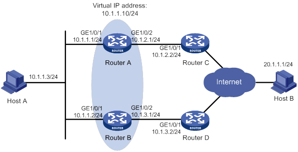
Configuration procedure
1. Configure the IP address of each interface, as shown in Figure 10. (Details not shown.)
2. Configure an NQA operation on Router A:
# Create an NQA operation with administrator name admin and operation tag test.
<RouterA> system-view
[RouterA] nqa entry admin test
# Specify the ICMP echo operation type.
[RouterA-nqa-admin-test] type icmp-echo
# Specify 10.1.2.2 as the destination address of ICMP echo requests.
[RouterA-nqa-admin-test-icmp-echo] destination ip 10.1.2.2
# Configure the ICMP echo operation to repeat every 100 milliseconds.
[RouterA-nqa-admin-test-icmp-echo] frequency 100
# Create reaction entry 1, specifying that five consecutive probe failures trigger the Track module.
[RouterA-nqa-admin-test-icmp-echo] reaction 1 checked-element probe-fail threshold-type consecutive 5 action-type trigger-only
[RouterA-nqa-admin-test-icmp-echo] quit
# Start the NQA operation.
[RouterA] nqa schedule admin test start-time now lifetime forever
3. On Router A, configure track entry 1, and associate it with reaction entry 1 of the NQA operation.
[RouterA] track 1 nqa entry admin test reaction 1
[RouterA-track-1] quit
4. Configure VRRP on Router A:
# Specify VRRPv2 to run on GigabitEthernet 1/0/1.
[RouterA] interface gigabitethernet 1/0/1
[RouterA-GigabitEthernet1/0/1] vrrp version 2
# Create VRRP group 1, and configure virtual IP address 10.1.1.10 for the group.
[RouterA-GigabitEthernet1/0/1] vrrp vrid 1 virtual-ip 10.1.1.10
# Set the priority of Router A to 110 in VRRP group 1.
[RouterA-GigabitEthernet1/0/1] vrrp vrid 1 priority 110
# Set the authentication mode of VRRP group 1 to simple, and the authentication key to hello.
[RouterA-GigabitEthernet1/0/1] vrrp vrid 1 authentication-mode simple plain hello
# Configure the master to send VRRP packets every 500 centiseconds.
[RouterA-GigabitEthernet1/0/1] vrrp vrid 1 timer advertise 500
# Configure Router A to operate in preemptive mode and set the preemption delay to 5000 centiseconds.
[RouterA-GigabitEthernet1/0/1] vrrp vrid 1 preempt-mode delay 5000
# Associate VRRP group 1 with track entry 1 and decrease the router priority by 30 when the state of track entry 1 changes to Negative.
[RouterA-GigabitEthernet1/0/1] vrrp vrid 1 track 1 priority reduced 30
5. Configure VRRP on Router B:
# Specify VRRPv2 to run on GigabitEthernet 1/0/1.
<RouterB> system-view
[RouterB] interface gigabitethernet 1/0/1
[RouterB-GigabitEthernet1/0/1] vrrp version 2
# Create VRRP group 1, and configure virtual IP address 10.1.1.10 for the group.
[RouterB-GigabitEthernet1/0/1] vrrp vrid 1 virtual-ip 10.1.1.10
# Set the authentication mode of VRRP group 1 to simple, and the authentication key to hello.
[RouterB-GigabitEthernet1/0/1] vrrp vrid 1 authentication-mode simple plain hello
# Configure the master to send VRRP packets every 500 centiseconds.
[RouterB-GigabitEthernet1/0/1] vrrp vrid 1 timer advertise 500
# Configure Router B to operate in preemptive mode and set the preemption delay to 5000 centiseconds.
[RouterB-GigabitEthernet1/0/1] vrrp vrid 1 preempt-mode delay 5000
Verifying the configuration
# Ping Host B from Host A to verify that Host B is reachable. (Details not shown.)
# Display detailed information about VRRP group 1 on Router A.
[RouterA-GigabitEthernet1/0/1] display vrrp verbose
IPv4 Virtual Router Information:
Running Mode : Standard
Total number of virtual routers : 1
Interface GigabitEthernet1/0/1
VRID : 1 Adver Timer : 500
Admin Status : Up State : Master
Config Pri : 110 Running Pri : 110
Preempt Mode : Yes Delay Time : 5000
Auth Type : Simple Key : ******
Virtual IP : 10.1.1.10
Virtual MAC : 0000-5e00-0101
Master IP : 10.1.1.1
VRRP Track Information:
Track Object : 1 State : Positive Pri Reduced : 30
# Display detailed information about VRRP group 1 on Router B.
[RouterB-GigabitEthernet1/0/1] display vrrp verbose
IPv4 Virtual Router Information:
Running Mode : Standard
Total number of virtual routers : 1
Interface GigabitEthernet1/0/1
VRID : 1 Adver Timer : 500
Admin Status : Up State : Backup
Config Pri : 100 Running Pri : 100
Preempt Mode : Yes Delay Time : 5000
Become Master : 2200ms left
Auth Type : Simple Key : ******
Virtual IP : 10.1.1.10
Master IP : 10.1.1.1
The output shows that in VRRP group 1, Router A is the master and Router B is a backup. Router A forwards packets from Host A to Host B.
# Disconnect the link between Router A and Router C, and verify that Host A can still ping Host B. (Details not shown.)
# Display detailed information about VRRP group 1 on Router A.
[RouterA-GigabitEthernet1/0/1] display vrrp verbose
IPv4 Virtual Router Information:
Running Mode : Standard
Total number of virtual routers : 1
Interface GigabitEthernet1/0/1
VRID : 1 Adver Timer : 500
Admin Status : Up State : Backup
Config Pri : 110 Running Pri : 80
Preempt Mode : Yes Delay Time : 5000
Become Master : 2200ms left
Auth Type : Simple Key : ******
Virtual IP : 10.1.1.10
Master IP : 10.1.1.2
VRRP Track Information:
Track Object : 1 State : Negative Pri Reduced : 30
# Display detailed information about VRRP group 1 on Router B when a fault is on the link between Router A and Router C.
[RouterB-GigabitEthernet1/0/1] display vrrp verbose
IPv4 Virtual Router Information:
Running Mode : Standard
Total number of virtual routers : 1
Interface GigabitEthernet1/0/1
VRID : 1 Adver Timer : 500
Admin Status : Up State : Master
Config Pri : 100 Running Pri : 100
Preempt Mode : Yes Delay Time : 5000
Auth Type : Simple Key : ******
Virtual IP : 10.1.1.10
Virtual MAC : 0000-5e00-0101
Master IP : 10.1.1.2
The output shows that Router A becomes the backup, and Router B becomes the master. Router B forwards packets from Host A to Host B.
Configuring BFD for a VRRP backup to monitor the master
Network requirements
As shown in Figure 11:
· Router A and Router B belong to VRRP group 1. The virtual IP address of VRRP group 1 is 192.168.0.10.
· The default gateway of the hosts in the LAN is 192.168.0.10.
Configure VRRP-Track-BFD collaboration to monitor the master on the backup and meet the following requirements:
· When Router A operates correctly, the hosts in the LAN access the Internet through Router A.
· When Router A fails, the backup (Router B) can detect the state change of the master through BFD and become the new master. The hosts in the LAN access the Internet through Router B.
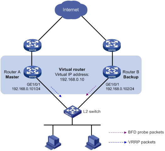
Configuration procedure
1. Configure Router A:
# Create VRRP group 1, and configure virtual IP address 192.168.0.10 for the group.
<RouterA> system-view
[RouterA] interface gigabitethernet 1/0/1
[RouterA-GigabitEthernet1/0/1] vrrp vrid 1 virtual-ip 192.168.0.10
# Set the priority of Router A to 110 in VRRP group 1.
[RouterA-GigabitEthernet1/0/1] vrrp vrid 1 priority 110
[RouterA-GigabitEthernet1/0/1] return
2. Configure Router B:
# Specify 10.10.10.10 as the source address of BFD echo packets.
<RouterB> system-view
[RouterB] bfd echo-source-ip 10.10.10.10
# Create track entry 1, and associate it with the BFD session to verify the reachability of Router A.
[RouterB] track 1 bfd echo interface gigabitethernet 1/0/1 remote ip 192.168.0.101 local ip 192.168.0.102
[RouterB-track-1] quit
# Create VRRP group 1, and configure virtual IP address 192.168.0.10 for the group.
[RouterB] interface gigabitethernet 1/0/1
[RouterB-GigabitEthernet1/0/1] vrrp vrid 1 virtual-ip 192.168.0.10
# Configure VRRP group 1 to monitor the status of track entry 1.
[RouterB-GigabitEthernet1/0/1] vrrp vrid 1 track 1 switchover
[RouterB-GigabitEthernet1/0/1] return
Verifying the configuration
# Display detailed information about VRRP group 1 on Router A.
<RouterA> display vrrp verbose
IPv4 Virtual Router Information:
Running Mode : Standard
Total number of virtual routers : 1
Interface GigabitEthernet1/0/1
VRID : 1 Adver Timer : 100
Admin Status : Up State : Master
Config Pri : 110 Running Pri : 110
Preempt Mode : Yes Delay Time : 0
Auth Type : None
Virtual IP : 192.168.0.10
Virtual MAC : 0000-5e00-0101
Master IP : 192.168.0.101
# Display detailed information about VRRP group 1 on Router B.
<RouterB> display vrrp verbose
IPv4 Virtual Router Information:
Running Mode : Standard
Total number of virtual routers : 1
Interface GigabitEthernet1/0/1
VRID : 1 Adver Timer : 100
Admin Status : Up State : Backup
Config Pri : 100 Running Pri : 100
Preempt Mode : Yes Delay Time : 0
Become Master : 2200ms left
Auth Type : None
Virtual IP : 192.168.0.10
Master IP : 192.168.0.101
VRRP Track Information:
Track Object : 1 State : Positive Switchover
# Display information about track entry 1 on Router B.
<RouterB> display track 1
Track ID: 1
State: Positive
Duration: 0 days 0 hours 0 minutes 32 seconds
Tracked object type: BFD
Notification delay: Positive 0, Negative 0 (in seconds)
Tracked object:
BFD session mode: Echo
Outgoing Interface: GigabitEthernet1/0/1
VPN instance name: --
Remote IP: 192.168.0.101
Local IP: 192.168.0.102
The output shows that when the status of the track entry becomes Positive, Router A is the master, and Router B the backup.
# Enable VRRP state debugging and BFD event notification debugging on Router B.
<RouterB> terminal debugging
<RouterB> terminal monitor
<RouterB> debugging vrrp fsm
<RouterB> debugging bfd ntfy
# When Router A fails, the following output is displayed on Router B.
*Dec 17 14:44:34:142 2008 RouterB BFD/7/DEBUG: Notify application:TRACK State:DOWN
*Dec 17 14:44:34:144 2008 RouterB VRRP4/7/FSM
IPv4 GigabitEthernet1/0/1 | Virtual Router 1 : Backup --> Master reason: The status of the tracked object changed
# Display detailed information about the VRRP group on Router B.
<RouterB> display vrrp verbose
IPv4 Virtual Router Information:
Running Mode : Standard
Total number of virtual routers : 1
Interface GigabitEthernet1/0/1
VRID : 1 Adver Timer : 100
Admin Status : Up State : Master
Config Pri : 100 Running Pri : 100
Preempt Mode : Yes Delay Time : 0
Auth Type : None
Virtual IP : 192.168.0.10
Virtual MAC : 0000-5e00-0101
Master IP : 192.168.0.102
VRRP Track Information:
Track Object : 1 State : Negative Switchover
The output shows that when BFD detects that Router A fails, the Track module notifies VRRP to change the status of Router B to master. The backup can quickly preempt as the master without waiting for a period three times the advertisement interval plus the Skew_Time.
Configuring BFD for the VRRP master to monitor the uplink
Network requirements
As shown in Figure 12:
· Router A and Router B belong to VRRP group 1. The virtual IP address of VRRP group 1 is 192.168.0.10.
· The default gateway of the hosts in the LAN is 192.168.0.10.
Configure VRRP-Track-BFD collaboration to monitor the uplink on the master and meet the following requirements:
· When Router A operates correctly, hosts in the LAN access the Internet through Router A.
· When Router A detects that the uplink is down through BFD, Router B can preempt as the master. The hosts in the LAN can access the Internet through Router B.
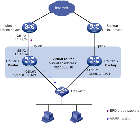
Configuration procedure
1. Configure Router A:
# Specify 10.10.10.10 as the source address of BFD echo packets.
<RouterA> system-view
[RouterA] bfd echo-source-ip 10.10.10.10
# Create track entry 1 for the BFD session on Router A to verify the reachability of the uplink device (1.1.1.2).
[RouterA] track 1 bfd echo interface gigabitethernet 1/0/1 remote ip 1.1.1.2 local ip 1.1.1.1
[RouterA-track-1] quit
# Create VRRP group 1, and specify 192.168.0.10 as the virtual IP address of the group.
[RouterA] interface gigabitethernet 1/0/2
[RouterA-GigabitEthernet1/0/2] vrrp vrid 1 virtual-ip 192.168.0.10
# Set the priority of Router A to 110 in VRRP group 1.
[RouterA-GigabitEthernet1/0/2] vrrp vrid 1 priority 110
# Associate VRRP group 1 with track entry 1 and decrease the router priority by 20 when the state of track entry 1 changes to Negative.
[RouterA-GigabitEthernet1/0/2] vrrp vrid 1 track 1 priority reduced 20
[RouterA-GigabitEthernet1/0/2] return
2. On Router B, create VRRP group 1, and specify 192.168.0.10 as the virtual IP address of the group.
<RouterB> system-view
[RouterB] interface gigabitethernet 1/0/2
[RouterB-GigabitEthernet1/0/2] vrrp vrid 1 virtual-ip 192.168.0.10
[RouterB-GigabitEthernet1/0/2] return
Verifying the configuration
# Display detailed information about the VRRP group on Router A.
<RouterA> display vrrp verbose
IPv4 Virtual Router Information:
Running Mode : Standard
Total number of virtual routers : 1
Interface GigabitEthernet1/0/2
VRID : 1 Adver Timer : 100
Admin Status : Up State : Master
Config Pri : 110 Running Pri : 110
Preempt Mode : Yes Delay Time : 0
Auth Type : None
Virtual IP : 192.168.0.10
Virtual MAC : 0000-5e00-0101
Master IP : 192.168.0.101
VRRP Track Information:
Track Object : 1 State : Positive Pri Reduced : 20
# Display information about track entry 1 on Router A.
<RouterA> display track 1
Track ID: 1
State: Positive
Duration: 0 days 0 hours 0 minutes 32 seconds
Tracked object type: BFD
Notification delay: Positive 0, Negative 0 (in seconds)
Tracked object:
BFD session mode: Echo
Outgoing interface: GigabitEthernet1/0/1
VPN instance name: --
Remote IP: 1.1.1.2
Local IP: 1.1.1.1
# Display detailed information about the VRRP group on Router B.
<RouterB> display vrrp verbose
IPv4 Virtual Router Information:
Running Mode : Standard
Total number of virtual routers : 1
Interface GigabitEthernet1/0/2
VRID : 1 Adver Timer : 100
Admin Status : Up State : Backup
Config Pri : 100 Running Pri : 100
Preempt Mode : Yes Delay Time : 0
Become Master : 2200ms left
Auth Type : None
Virtual IP : 192.168.0.10
Master IP : 192.168.0.101
The output shows that when the status of track entry 1 becomes Positive, Router A is the master and Router B the backup.
# Display information about track entry 1 when the uplink of Router A goes down.
<RouterA> display track 1
Track ID: 1
State: Negative
Duration: 0 days 0 hours 0 minutes 32 seconds
Tracked object type: BFD
Notification delay: Positive 0, Negative 0 (in seconds)
Tracked object:
BFD session mode: Echo
Outgoing interface: GigabitEthernet1/0/1
VPN instance name: --
Remote IP: 1.1.1.2
Local IP: 1.1.1.1
# Display detailed information about the VRRP group on Router A.
<RouterA> display vrrp verbose
IPv4 Virtual Router Information:
Running Mode : Standard
Total number of virtual routers : 1
Interface GigabitEthernet1/0/2
VRID : 1 Adver Timer : 100
Admin Status : Up State : Backup
Config Pri : 110 Running Pri : 90
Preempt Mode : Yes Delay Time : 0
Become Master : 2200ms left
Auth Type : None
Virtual IP : 192.168.0.10
Master IP : 192.168.0.102
VRRP Track Information:
Track Object : 1 State : Negative Pri Reduced : 20
# Display detailed information about VRRP group 1 on Router B.
<RouterB> display vrrp verbose
IPv4 Virtual Router Information:
Running Mode : Standard
Total number of virtual routers : 1
Interface GigabitEthernet1/0/2
VRID : 1 Adver Timer : 100
Admin Status : Up State : Master
Config Pri : 100 Running Pri : 100
Preempt Mode : Yes Delay Time : 0
Auth Type : None
Virtual IP : 192.168.0.10
Virtual MAC : 0000-5e00-0101
Master IP : 192.168.0.102
The output shows that when Router A detects that the uplink fails through BFD, it decreases its priority by 20. Router B then preempts as the master.
Static routing-Track-NQA collaboration configuration example
Network requirements
As shown in Figure 13:
· Router A is the default gateway of the hosts in network 20.1.1.0/24.
· Router D is the default gateway of the hosts in network 30.1.1.0/24.
· Hosts in the two networks communicate with each other through static routes.
To ensure network availability, configure route backup and static routing-Track-NQA collaboration on Router A and Router D as follows:
· On Router A, assign a higher priority to the static route to 30.1.1.0/24 with next hop Router B. This route is the master route. The static route to 30.1.1.0/24 with next hop Router C acts as the backup route. When the master route is unavailable, the backup route takes effect.
· On Router D, assign a higher priority to the static route to 20.1.1.0/24 with next hop Router B. This route is the master route. The static route to 20.1.1.0/24 with next hop Router C acts as the backup route. When the master route is unavailable, the backup route takes effect.
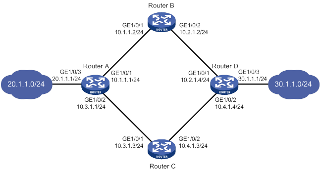
Configuration procedure
1. Configure the IP address of each interface, as shown in Figure 13. (Details not shown.)
2. Configure Router A:
# Configure a static route to 30.1.1.0/24 with next hop 10.1.1.2 and the default priority (60). Associate this static route with track entry 1.
<RouterA> system-view
[RouterA] ip route-static 30.1.1.0 24 10.1.1.2 track 1
# Configure a static route to 30.1.1.0/24 with next hop 10.3.1.3 and priority 80.
[RouterA] ip route-static 30.1.1.0 24 10.3.1.3 preference 80
# Configure a static route to 10.2.1.4 with next hop 10.1.1.2.
[RouterA] ip route-static 10.2.1.4 24 10.1.1.2
# Create an NQA operation with administrator name admin and operation tag test.
[RouterA] nqa entry admin test
# Specify the ICMP echo operation type.
[RouterA-nqa-admin-test] type icmp-echo
# Specify 10.2.1.4 as the destination address of the operation.
[RouterA-nqa-admin-test-icmp-echo] destination ip 10.2.1.4
# Specify 10.1.1.2 as the next hop of the operation.
[RouterA-nqa-admin-test-icmp-echo] next-hop ip 10.1.1.2
# Configure the ICMP echo operation to repeat every 100 milliseconds.
[RouterA-nqa-admin-test-icmp-echo] frequency 100
# Configure reaction entry 1, specifying that five consecutive probe failures trigger the Track module.
[RouterA-nqa-admin-test-icmp-echo] reaction 1 checked-element probe-fail threshold-type consecutive 5 action-type trigger-only
[RouterA-nqa-admin-test-icmp-echo] quit
# Start the NQA operation.
[RouterA] nqa schedule admin test start-time now lifetime forever
# Configure track entry 1, and associate it with reaction entry 1 of the NQA operation.
[RouterA] track 1 nqa entry admin test reaction 1
[RouterA-track-1] quit
3. Configure Router B:
# Configure a static route to 30.1.1.0/24 with next hop 10.2.1.4.
<RouterB> system-view
[RouterB] ip route-static 30.1.1.0 24 10.2.1.4
# Configure a static route to 20.1.1.0/24 with next hop 10.1.1.1.
[RouterB] ip route-static 20.1.1.0 24 10.1.1.1
4. Configure Router C:
# Configure a static route to 30.1.1.0/24 with next hop 10.4.1.4.
<RouterC> system-view
[RouterC] ip route-static 30.1.1.0 24 10.4.1.4
# Configure a static route to 20.1.1.0/24 with next hop 10.3.1.1.
[RouterC] ip route-static 20.1.1.0 24 10.3.1.1
5. Configure Router D:
# Configure a static route to 20.1.1.0/24 with next hop 10.2.1.2 and the default priority (60). Associate this static route with track entry 1.
<RouterD> system-view
[RouterD] ip route-static 20.1.1.0 24 10.2.1.2 track 1
# Configure a static route to 20.1.1.0/24 with next hop 10.4.1.3 and priority 80.
[RouterD] ip route-static 20.1.1.0 24 10.4.1.3 preference 80
# Configure a static route to 10.1.1.1 with next hop 10.2.1.2.
[RouterD] ip route-static 10.1.1.1 24 10.2.1.2
# Create an NQA operation with administrator name admin and operation tag test.
[RouterD] nqa entry admin test
# Specify the ICMP echo operation type.
[RouterD-nqa-admin-test] type icmp-echo
# Specify 10.1.1.1 as the destination address of the operation.
[RouterD-nqa-admin-test-icmp-echo] destination ip 10.1.1.1
# Specify 10.2.1.2 as the next hop of the operation.
[RouterD-nqa-admin-test-icmp-echo] next-hop ip 10.2.1.2
# Configure the ICMP echo operation to repeat every 100 milliseconds.
[RouterD-nqa-admin-test-icmp-echo] frequency 100
# Configure reaction entry 1, specifying that five consecutive probe failures trigger the Track module.
[RouterD-nqa-admin-test-icmp-echo] reaction 1 checked-element probe-fail threshold-type consecutive 5 action-type trigger-only
[RouterD-nqa-admin-test-icmp-echo] quit
# Start the NQA operation.
[RouterD] nqa schedule admin test start-time now lifetime forever
# Configure track entry 1, and associate it with reaction entry 1 of the NQA operation.
[RouterD] track 1 nqa entry admin test reaction 1
[RouterD-track-1] quit
Verifying the configuration
# Display track entry information on Router A.
[RouterA] display track all
Track ID: 1
State: Positive
Duration: 0 days 0 hours 0 minutes 32 seconds
Tracked object type: NQA
Notification delay: Positive 0, Negative 0 (in seconds)
Tracked object:
NQA entry: admin test
Reaction: 1
Remote IP/URL: 20.1.1.7
Local IP:--
Interface:--
The output shows that the status of track entry 1 is Positive, indicating that the NQA operation has succeeded and the master route is available.
# Display the routing table of Router A.
[RouterA] display ip routing-table
Destinations : 10 Routes : 10
Destination/Mask Proto Pre Cost NextHop Interface
10.1.1.0/24 Direct 0 0 10.1.1.1 GE1/0/1
10.1.1.1/32 Direct 0 0 127.0.0.1 InLoop0
10.2.1.0/24 Static 60 0 10.1.1.2 GE1/0/1
10.3.1.0/24 Direct 0 0 10.3.1.1 GE1/0/2
10.3.1.1/32 Direct 0 0 127.0.0.1 InLoop0
20.1.1.0/24 Direct 0 0 20.1.1.1 GE1/0/3
20.1.1.1/32 Direct 0 0 127.0.0.1 InLoop0
30.1.1.0/24 Static 60 0 10.1.1.2 GE1/0/1
127.0.0.0/8 Direct 0 0 127.0.0.1 InLoop0
127.0.0.1/32 Direct 0 0 127.0.0.1 InLoop0
The output shows that Router A forwards packets to 30.1.1.0/24 through Router B.
# Remove the IP address of GigabitEthernet 1/0/1 on Router B.
<RouterB> system-view
[RouterB] interface gigabitethernet 1/0/1
[RouterB-GigabitEthernet1/0/1] undo ip address
# Display information about the track entry on Router A.
[RouterA] display track all
Track ID: 1
State: Negative
Duration: 0 days 0 hours 0 minutes 32 seconds
Tracked object type: NQA
Notification delay: Positive 0, Negative 0 (in seconds)
Tracked object:
NQA entry: admin test
Reaction: 1
Remote IP/URL: 20.1.1.7
Local IP:--
Interface:--
The output shows that the status of the track entry is Negative, indicating that the NQA operation has failed and the master route is unavailable.
# Display the routing table of Router A.
[RouterA] display ip routing-table
Destinations : 10 Routes : 10
Destination/Mask Proto Pre Cost NextHop Interface
10.1.1.0/24 Direct 0 0 10.1.1.1 GE1/0/1
10.1.1.1/32 Direct 0 0 127.0.0.1 InLoop0
10.2.1.0/24 Static 60 0 10.1.1.2 GE1/0/1
10.3.1.0/24 Direct 0 0 10.3.1.1 GE1/0/2
10.3.1.1/32 Direct 0 0 127.0.0.1 InLoop0
20.1.1.0/24 Direct 0 0 20.1.1.1 GE1/0/3
20.1.1.1/32 Direct 0 0 127.0.0.1 InLoop0
30.1.1.0/24 Static 80 0 10.3.1.3 GE1/0/2
127.0.0.0/8 Direct 0 0 127.0.0.1 InLoop0
127.0.0.1/32 Direct 0 0 127.0.0.1 InLoop0
The output shows that Router A forwards packets to 30.1.1.0/24 through Router C. The backup static route has taken effect.
# Verify that hosts in 20.1.1.0/24 can communicate with the hosts in 30.1.1.0/24 when the master route fails.
[RouterA] ping -a 20.1.1.1 30.1.1.1
Ping 30.1.1.1: 56 data bytes, press CTRL_C to break
Reply from 30.1.1.1: bytes=56 Sequence=1 ttl=254 time=2 ms
Reply from 30.1.1.1: bytes=56 Sequence=2 ttl=254 time=1 ms
Reply from 30.1.1.1: bytes=56 Sequence=3 ttl=254 time=1 ms
Reply from 30.1.1.1: bytes=56 Sequence=4 ttl=254 time=2 ms
Reply from 30.1.1.1: bytes=56 Sequence=5 ttl=254 time=1 ms
--- Ping statistics for 30.1.1.1 ---
5 packet(s) transmitted, 5 packet(s) received, 0.00% packet loss
round-trip min/avg/max/std-dev = 1/1/2/1 ms
# Verify that the hosts in 30.1.1.0/24 can communicate with the hosts in 20.1.1.0/24 when the master route fails.
[RouterD] ping -a 30.1.1.1 20.1.1.1
Ping 20.1.1.1: 56 data bytes, press CTRL_C to break
Reply from 20.1.1.1: bytes=56 Sequence=1 ttl=254 time=2 ms
Reply from 20.1.1.1: bytes=56 Sequence=2 ttl=254 time=1 ms
Reply from 20.1.1.1: bytes=56 Sequence=3 ttl=254 time=1 ms
Reply from 20.1.1.1: bytes=56 Sequence=4 ttl=254 time=1 ms
Reply from 20.1.1.1: bytes=56 Sequence=5 ttl=254 time=1 ms
--- Ping statistics for 20.1.1.1 ---
5 packet(s) transmitted, 5 packet(s) received, 0.00% packet loss
round-trip min/avg/max/std-dev = 1/1/2/1 ms
Static routing-Track-BFD collaboration configuration example
Network requirements
As shown in Figure 14:
· Router A is the default gateway of the hosts in network 20.1.1.0/24.
· Router B is the default gateway of the hosts in network 30.1.1.0/24.
· Hosts in the two networks communicate with each other through static routes.
To ensure network availability, configure route backup and static routing-Track-BFD collaboration on Router A and Router B as follows:
· On Router A, assign a higher priority to the static route to 30.1.1.0/24 with next hop Router B. This route is the master route. The static route to 30.1.1.0/24 with next hop Router C acts as the backup route. When the master route is unavailable, BFD can quickly detect the route failure to make the backup route take effect.
· On Router B, assign a higher priority to the static route to 20.1.1.0/24 with next hop Router A. This route is the master route. The static route to 20.1.1.0/24 with next hop Router C acts as the backup route. When the master route is unavailable, BFD can quickly detect the route failure to make the backup route take effect.
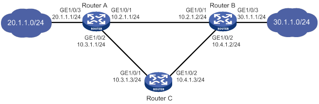
Configuration procedure
1. Configure the IP address of each interface, as shown in Figure 14. (Details not shown.)
2. Configure Router A:
# Configure a static route to 30.1.1.0/24 with next hop 10.2.1.2 and the default priority (60). Associate this static route with track entry 1.
<RouterA> system-view
[RouterA] ip route-static 30.1.1.0 24 10.2.1.2 track 1
# Configure a static route to 30.1.1.0/24 with next hop 10.3.1.3 and priority 80.
[RouterA] ip route-static 30.1.1.0 24 10.3.1.3 preference 80
# Specify 10.10.10.10 as the source address of BFD echo packets.
[RouterA] bfd echo-source-ip 10.10.10.10
# Configure track entry 1, and associate it with the BFD session to verify the connectivity between Router A and Router B.
[RouterA] track 1 bfd echo interface gigabitethernet 1/0/1 remote ip 10.2.1.2 local ip 10.2.1.1
[RouterA-track-1] quit
3. Configure Router B:
# Configure a static route to 20.1.1.0/24 with next hop 10.2.1.1 and the default priority (60). Associate this static route with track entry 1.
<RouterB> system-view
[RouterB] ip route-static 20.1.1.0 24 10.2.1.1 track 1
# Configure a static route to 20.1.1.0/24 with next hop 10.4.1.3 and priority 80.
[RouterB] ip route-static 20.1.1.0 24 10.4.1.3 preference 80
# Specify 1.1.1.1 as the source address of BFD echo packets.
[RouterB] bfd echo-source-ip 1.1.1.1
# Configure track entry 1, and associate it with the BFD session to verify the connectivity between Router B and Router A.
[RouterB] track 1 bfd echo interface gigabitethernet 1/0/1 remote ip 10.2.1.1 local ip 10.2.1.2
[RouterB-track-1] quit
4. Configure Router C:
# Configure a static route to 30.1.1.0/24 with next hop 10.4.1.2.
<RouterC> system-view
[RouterC] ip route-static 30.1.1.0 24 10.4.1.2
# Configure a static route to 20.1.1.0/24 with next hop 10.3.1.1.
[RouterB] ip route-static 20.1.1.0 24 10.3.1.1
Verifying the configuration
# Display information about the track entry on Router A.
[RouterA] display track all
Track ID: 1
State: Positive
Duration: 0 days 0 hours 0 minutes 32 seconds
Tracked object type: BFD
Notification delay: Positive 0, Negative 0 (in seconds)
Tracked object:
BFD session mode: Echo
Outgoing interface: GigabitEthernet1/0/1
VPN instance name: --
Remote IP: 10.2.1.2
Local IP: 10.2.1.1
The output shows that the status of the track entry is Positive, indicating that next hop 10.2.1.2 is reachable.
# Display the routing table of Router A.
[RouterA] display ip routing-table
Destinations : 9 Routes : 9
Destination/Mask Proto Pre Cost NextHop Interface
10.2.1.0/24 Direct 0 0 10.2.1.1 GE1/0/1
10.2.1.1/32 Direct 0 0 127.0.0.1 InLoop0
10.3.1.0/24 Direct 0 0 10.3.1.1 GE1/0/2
10.3.1.1/32 Direct 0 0 127.0.0.1 InLoop0
20.1.1.0/24 Direct 0 0 20.1.1.1 GE1/0/3
20.1.1.1/32 Direct 0 0 127.0.0.1 InLoop0
30.1.1.0/24 Static 60 0 10.2.1.2 GE1/0/1
127.0.0.0/8 Direct 0 0 127.0.0.1 InLoop0
127.0.0.1/32 Direct 0 0 127.0.0.1 InLoop0
The output shows that Router A forwards packets to 30.1.1.0/24 through Router B. The master static route has taken effect.
# Remove the IP address of GigabitEthernet 1/0/1 on Router B.
<RouterB> system-view
[RouterB] interface gigabitethernet 1/0/1
[RouterB-GigabitEthernet1/0/1] undo ip address
# Display information about the track entry on Router A.
[RouterA] display track all
Track ID: 1
State: Negative
Duration: 0 days 0 hours 0 minutes 32 seconds
Tracked object type: BFD
Notification delay: Positive 0, Negative 0 (in seconds)
Tracked object:
BFD session mode: Echo
Outgoing interface: GigabitEthernet1/0/1
VPN instance name: --
Remote IP: 10.2.1.2
Local IP: 10.2.1.1
The output shows that the status of the track entry is Negative, indicating that next hop 10.2.1.2 is unreachable.
# Display the routing table of Router A.
[RouterA] display ip routing-table
Destinations : 9 Routes : 9
Destination/Mask Proto Pre Cost NextHop Interface
10.2.1.0/24 Direct 0 0 10.2.1.1 GE1/0/1
10.2.1.1/32 Direct 0 0 127.0.0.1 InLoop0
10.3.1.0/24 Direct 0 0 10.3.1.1 GE1/0/2
10.3.1.1/32 Direct 0 0 127.0.0.1 InLoop0
20.1.1.0/24 Direct 0 0 20.1.1.1 GE1/0/3
20.1.1.1/32 Direct 0 0 127.0.0.1 InLoop0
30.1.1.0/24 Static 80 0 10.3.1.3 GE1/0/2
127.0.0.0/8 Direct 0 0 127.0.0.1 InLoop0
127.0.0.1/32 Direct 0 0 127.0.0.1 InLoop0
The output shows that Router A forwards packets to 30.1.1.0/24 through Router C. The backup static route has taken effect.
# Verify that the hosts in 20.1.1.0/24 can communicate with the hosts in 30.1.1.0/24 when the master route fails.
[RouterA] ping -a 20.1.1.1 30.1.1.1
Ping 30.1.1.1: 56 data bytes, press CTRL_C to break
Reply from 30.1.1.1: bytes=56 Sequence=1 ttl=254 time=2 ms
Reply from 30.1.1.1: bytes=56 Sequence=2 ttl=254 time=1 ms
Reply from 30.1.1.1: bytes=56 Sequence=3 ttl=254 time=1 ms
Reply from 30.1.1.1: bytes=56 Sequence=4 ttl=254 time=2 ms
Reply from 30.1.1.1: bytes=56 Sequence=5 ttl=254 time=1 ms
--- Ping statistics for 30.1.1.1 ---
5 packet(s) transmitted, 5 packet(s) received, 0.00% packet loss
round-trip min/avg/max/std-dev = 1/1/2/1 ms
# Verify that the hosts in 30.1.1.0/24 can communicate with the hosts in 20.1.1.0/24 when the master route fails.
[RouterB] ping -a 30.1.1.1 20.1.1.1
Ping 20.1.1.1: 56 data bytes, press CTRL_C to break
Reply from 20.1.1.1: bytes=56 Sequence=1 ttl=254 time=2 ms
Reply from 20.1.1.1: bytes=56 Sequence=2 ttl=254 time=1 ms
Reply from 20.1.1.1: bytes=56 Sequence=3 ttl=254 time=1 ms
Reply from 20.1.1.1: bytes=56 Sequence=4 ttl=254 time=1 ms
Reply from 20.1.1.1: bytes=56 Sequence=5 ttl=254 time=1 ms
--- Ping statistics for 20.1.1.1 ---
5 packet(s) transmitted, 5 packet(s) received, 0.00% packet loss
round-trip min/avg/max/std-dev = 1/1/2/1 ms
VRRP-Track-interface management collaboration configuration example
Network requirements
As shown in Figure 15:
· Host A requires access to Host B. The default gateway of Host A is 10.1.1.10/24.
· Router A and Router B belong to VRRP group 1. The virtual IP address of VRRP group 1 is 10.1.1.10.
Configure VRRP-Track-interface management collaboration to monitor the uplink interface on the master and meet the following requirements:
· When Router A operates correctly, Router A forwards packets from Host A to Host B.
· When VRRP detects a fault on the uplink interface of Router A through the interface management module, Router B forwards packets from Host A to Host B.
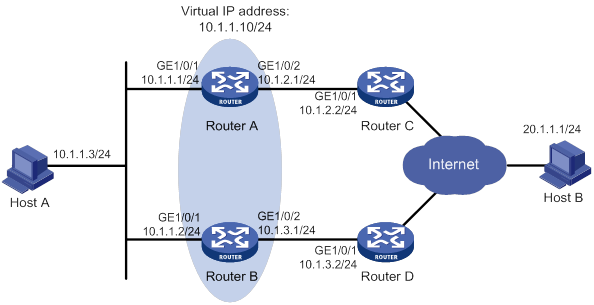
Configuration procedure
1. Configure the IP address of each interface, as shown in Figure 15. (Details not shown.)
2. Configure Router A:
# Configure track entry 1, and associate it with the link status of the uplink interface (GigabitEthernet 1/0/2).
[RouterA] track 1 interface gigabitethernet 1/0/2
[RouterA-track-1] quit
# Create VRRP group 1, and configure virtual IP address 10.1.1.10 for the group.
[RouterA] interface gigabitethernet 1/0/1
[RouterA-GigabitEthernet1/0/1] vrrp vrid 1 virtual-ip 10.1.1.10
# Set the priority of Router A to 110 in VRRP group 1.
[RouterA-GigabitEthernet1/0/1] vrrp vrid 1 priority 110
# Associate VRRP group 1 with track entry 1 and decrease the router priority by 30 when the state of track entry 1 changes to Negative.
[RouterA-GigabitEthernet1/0/1] vrrp vrid 1 track 1 priority reduced 30
3. On Router B, create VRRP group 1, and configure virtual IP address 10.1.1.10 for the group.
<RouterB> system-view
[RouterB] interface gigabitethernet 1/0/1
[RouterB-GigabitEthernet1/0/1] vrrp vrid 1 virtual-ip 10.1.1.10
Verifying the configuration
# Ping Host B from Host A to verify that Host B is reachable. (Details not shown.)
# Display detailed information about VRRP group 1 on Router A.
[RouterA-GigabitEthernet1/0/1] display vrrp verbose
IPv4 Virtual Router Information:
Running Mode : Standard
Total number of virtual routers : 1
Interface GigabitEthernet1/0/1
VRID : 1 Adver Timer : 100
Admin Status : Up State : Master
Config Pri : 110 Running Pri : 110
Preempt Mode : Yes Delay Time : 0
Auth Type : None
Virtual IP : 10.1.1.10
Virtual MAC : 0000-5e00-0101
Master IP : 10.1.1.1
VRRP Track Information:
Track Object : 1 State : Positive Pri Reduced : 30
# Display detailed information about VRRP group 1 on Router B.
[RouterB-GigabitEthernet1/0/1] display vrrp verbose
IPv4 Virtual Router Information:
Running Mode : Standard
Total number of virtual routers : 1
Interface GigabitEthernet1/0/1
VRID : 1 Adver Timer : 100
Admin Status : Up State : Backup
Config Pri : 100 Running Pri : 100
Preempt Mode : Yes Delay Time : 0
Become Master : 2200ms left
Auth Type : None
Virtual IP : 10.1.1.10
Master IP : 10.1.1.1
The output shows that in VRRP group 1, Router A is the master and Router B is a backup. Router A forwards packets from Host A to Host B.
# Shut down the uplink interface (GigabitEthernet 1/0/2) on Router A.
[RouterA-GigabitEthernet1/0/1] interface gigabitethernet 1/0/2
[RouterA-GigabitEthernet1/0/2] shutdown
# Ping Host B from Host A to verify that Host B is reachable. (Details not shown.)
# Display detailed information about VRRP group 1 on Router A.
[RouterA-GigabitEthernet1/0/2] display vrrp verbose
IPv4 Virtual Router Information:
Running Mode : Standard
Total number of virtual routers : 1
Interface GigabitEthernet1/0/1
VRID : 1 Adver Timer : 100
Admin Status : Up State : Backup
Config Pri : 110 Running Pri : 80
Preempt Mode : Yes Delay Time : 0
Become Master : 2200ms left
Auth Type : None
Virtual IP : 10.1.1.10
Master IP : 10.1.1.2
VRRP Track Information:
Track Object : 1 State : Negative Pri Reduced : 30
# Display detailed information about VRRP group 1 on Router B.
[RouterB-GigabitEthernet1/0/1] display vrrp verbose
IPv4 Virtual Router Information:
Running Mode : Standard
Total number of virtual routers : 1
Interface GigabitEthernet1/0/1
VRID : 1 Adver Timer : 100
Admin Status : Up State : Master
Config Pri : 100 Running Pri : 100
Preempt Mode : Yes Delay Time : 0
Auth Type : None
Virtual IP : 10.1.1.10
Virtual MAC : 0000-5e00-0101
Master IP : 10.1.1.2
The output shows that Router A becomes the backup, and Router B becomes the master. Router B forwards packets from Host A to Host B.
VRRP-Track-route management collaboration configuration example
Network requirements
As shown in Figure 16:
· Host A requires access to Host B. The default gateway of Host A is 10.1.1.10/24.
· Router A and Router B belong to VRRP group 1. The virtual IP address of VRRP group 1 is 10.1.1.10.
· BGP peer relationships are established between Router A and Router C and between Router B and Router D. Router C and Router D advertise default route 0.0.0.0/0 to Router A and Router B.
Configure VRRP-Track-route management collaboration to meet the following requirements:
· When Router A operates correctly, Router A forwards packets from Host A to Host B.
· When VRRP detects the removal of the default route from the routing table of Router A through route management, Router B forwards packets from Host A to Host B.
Configuration procedure
1. Configure the IP address of each interface, as shown in Figure 16. (Details not shown.)
2. Establish an IBGP peer relationship between Router A and Router C, and configure Router C to advertise default route 0.0.0.0/0 to Router A.
<RouterA> system-view
[RouterA] bgp 100
[RouterA-bgp-default] peer 10.1.2.2 as-number 100
[RouterA-bgp-default] address-family ipv4
[RouterA-bgp-default-ipv4] peer 10.1.2.2 enable
<RouterC> system-view
[RouterC] bgp 100
[RouterC-bgp-default] peer 10.1.2.1 as-number 100
[RouterC-bgp-default] address-family ipv4
[RouterC-bgp-default-ipv4] peer 10.1.2.1 enable
[RouterC-bgp-default-ipv4] peer 10.1.2.1 default-route-advertise
[RouterC-bgp-default-ipv4] quit
3. Configure Router B and Router D in the same way Router A and Router C are configured. (Details not shown.)
4. Configure Track and VRRP on Router A:
# Configure track entry 1, and associate it with default route 0.0.0.0/0.
[RouterA] track 1 ip route 0.0.0.0 0.0.0.0 reachability
[RouterA-track-1] quit
# Create VRRP group 1, and configure virtual IP address 10.1.1.10 for the group.
[RouterA] interface gigabitethernet 1/0/1
[RouterA-GigabitEthernet1/0/1] vrrp vrid 1 virtual-ip 10.1.1.10
# Set the priority of Router A to 110 in VRRP group 1.
[RouterA-GigabitEthernet1/0/1] vrrp vrid 1 priority 110
# Associate VRRP group 1 with track entry 1 and decrease the router priority by 30 when the state of track entry 1 changes to Negative.
[RouterA-GigabitEthernet1/0/1] vrrp vrid 1 track 1 priority reduced 30
[RouterA-GigabitEthernet1/0/1] quit
5. On Router B, create VRRP group 1, and configure virtual IP address 10.1.1.10 for the group.
<RouterB> system-view
[RouterB] interface gigabitethernet 1/0/1
[RouterB-GigabitEthernet1/0/1] vrrp vrid 1 virtual-ip 10.1.1.10
[RouterB-GigabitEthernet1/0/1] quit
Verifying the configuration
# Ping Host B from Host A to verify that Host B is reachable. (Details not shown.)
# Display detailed information about VRRP group 1 on Router A.
[RouterA] display vrrp verbose
IPv4 Virtual Router Information:
Running Mode : Standard
Total number of virtual routers : 1
Interface GigabitEthernet1/0/1
VRID : 1 Adver Timer : 100
Admin Status : Up State : Master
Config Pri : 110 Running Pri : 110
Preempt Mode : Yes Delay Time : 0
Auth Type : None
Virtual IP : 10.1.1.10
Virtual MAC : 0000-5e00-0101
Master IP : 10.1.1.1
VRRP Track Information:
Track Object : 1 State : Positive Pri Reduced : 30
# Display detailed information about VRRP group 1 on Router B.
[RouterB] display vrrp verbose
IPv4 Virtual Router Information:
Running Mode : Standard
Total number of virtual routers : 1
Interface GigabitEthernet1/0/1
VRID : 1 Adver Timer : 100
Admin Status : Up State : Backup
Config Pri : 100 Running Pri : 100
Preempt Mode : Yes Delay Time : 0
Become Master : 2200ms left
Auth Type : None
Virtual IP : 10.1.1.10
Master IP : 10.1.1.1
The output shows that in VRRP group 1, Router A is the master and Router B is a backup. Router A forwards packets from Host A to Host B.
# Disable Router C from exchanging routing information with Router A so that default route 0.0.0.0/0 is removed from Router A.
[RouterC-bgp-default-ipv4] undo peer 10.1.2.1 enable
# Ping Host B from Host A to verify that Host B is reachable. (Details not shown.)
# Display detailed information about VRRP group 1 on Router A.
[RouterA] display vrrp verbose
IPv4 Virtual Router Information:
Running Mode : Standard
Total number of virtual routers : 1
Interface GigabitEthernet1/0/1
VRID : 1 Adver Timer : 100
Admin Status : Up State : Backup
Config Pri : 110 Running Pri : 80
Preempt Mode : Yes Delay Time : 0
Become Master : 2200ms left
Auth Type : None
Virtual IP : 10.1.1.10
Master IP : 10.1.1.2
VRRP Track Information:
Track Object : 1 State : Negative Pri Reduced : 30
# Display detailed information about VRRP group 1 on Router B.
[RouterB] display vrrp verbose
IPv4 Virtual Router Information:
Running Mode : Standard
Total number of virtual routers : 1
Interface GigabitEthernet1/0/1
VRID : 1 Adver Timer : 100
Admin Status : Up State : Master
Config Pri : 100 Running Pri : 100
Preempt Mode : Yes Delay Time : 0
Auth Type : None
Virtual IP : 10.1.1.10
Virtual MAC : 0000-5e00-0101
Master IP : 10.1.1.2
The output shows that Router A becomes the backup, and Router B becomes the master. Router B forwards packets from Host A to Host B.
Configuring VRRP
Overview
Typically, you can configure a default gateway for every host on a LAN. All packets destined for other networks are sent through the default gateway. As shown in Figure 17, when the default gateway fails, no hosts can communicate with external networks.
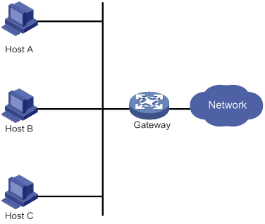
Using a default gateway facilitates your configuration but requires high availability. Using more egress gateways improves link availability but introduces the problem of routing among the egresses.
Virtual Router Redundancy Protocol (VRRP) is designed to address this issue. VRRP adds a group of network gateways to a VRRP group called a virtual router. The VRRP group has one master and multiple backups, and provides a virtual IP address. The hosts on the subnet use the virtual IP address as their default network gateway to communicate with external networks.
The virtual IP address of the virtual router can be either of the following IP addresses:
· Unused IP address on the subnet where the VRRP group resides.
· IP address of an interface on a router in the VRRP group.
In the latter case, the router is called the IP address owner. A VRRP group can have only one IP address owner.
VRRP avoids single points of failure and simplifies the configuration on hosts. When the master in the VRRP group on a multicast or broadcast LAN (for example, an Ethernet network) fails, another router in the VRRP group takes over. The switchover is complete without causing dynamic route recalculation, route re-discovery, gateway reconfiguration on the hosts, or traffic interruption.
VRRP operates in either of the following modes:
· Standard mode—Implemented based on RFCs. For more information, see "VRRP standard mode."
· Load balancing mode—Extends the VRRP standard mode to distribute load across VRRP group members. For more information, see "VRRP load balancing mode."
VRRP has two versions: VRRPv2 and VRRPv3. VRRPv2 supports IPv4 VRRP. VRRPv3 supports IPv4 VRRP and IPv6 VRRP.
VRRP standard mode
In VRRP standard mode, only the master in the VRRP group can provide gateway service. When the master fails, the backup routers elect a new master to take over for nonstop gateway service.
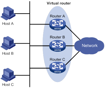
As shown in Figure 18, Router A, Router B, and Router C form a virtual router, which has its own IP address. Hosts on the subnet use the virtual router as the default gateway.
The router with the highest priority among the three routers is elected as the master, and the other two are backups.
Router priority in a VRRP group
VRRP determines the role (master or backup) of each router in a VRRP group by priority. A router with higher priority is more likely to become the master.
A VRRP priority can be in the range of 0 to 255, and a greater number represents a higher priority. Priorities 1 to 254 are configurable. Priority 0 is reserved for special uses, and priority 255 is for the IP address owner. The IP address owner in a VRRP group always has a running priority of 255 and acts as the master as long as it operates correctly.
Preemption
A router in a VRRP group operates in either non-preemptive mode or preemptive mode.
· Non-preemptive mode—The master router acts as the master as long as it operates correctly, even if a backup router is later assigned a higher priority. Non-preemptive mode helps avoid frequent switchover between the master and backup routers.
· Preemptive mode—A backup starts a new master election and takes over as master when it detects that it has a higher priority than the current master. Preemptive mode ensures that the router with the highest priority in a VRRP group always acts as the master.
Authentication method
To avoid attacks from unauthorized users, VRRP member routers add authentication keys in VRRP packets to authenticate one another. VRRP provides the following authentication methods:
· Simple authentication
The sender fills an authentication key into the VRRP packet, and the receiver compares the received authentication key with its local authentication key. If the two authentication keys match, the received VRRP packet is legitimate. Otherwise, the received packet is illegitimate and gets discarded.
· MD5 authentication
The sender computes a digest for the VRRP packet by using the authentication key and MD5 algorithm, and saves the result to the packet. The receiver performs the same operation with the authentication key and MD5 algorithm, and compares the result with the content in the authentication header. If the results match, the received VRRP packet is legitimate. Otherwise, the received packet is illegitimate and gets discarded.
On a secure network, you can choose to not authenticate VRRP packets.
|
|
NOTE: IPv4 VRRPv3 and IPv6 VRRPv3 do not support VRRP packet authentication. |
VRRP timers
Skew_Time
Skew_Time helps avoid the situation that multiple backups in a VRRP group become the master when the master in the VRRP group fails.
Skew_Time is not configurable; its value depends on the VRRP version.
· In VRRPv2 (described in RFC 3768), Skew_Time is (256 – Router priority)/256.
· In VRRPv3 (described in RFC 5798), Skew_Time is ((256 – Router priority) × VRRP advertisement interval)/256.
VRRP advertisement interval
The master in a VRRP group periodically sends VRRP advertisements to declare its presence.
You can configure the interval at which the master sends VRRP advertisements. If a backup does not receive any VRRP advertisement when the timer (3 × VRRP advertisement interval + Skew_Time) expires, it takes over as the master.
VRRP preemption delay timer
You can configure the VRRP preemption delay timer for the following purposes:
· Avoid frequent state changes among members in a VRRP group.
· Provide the backups with enough time to collect information (such as routing information).
In preempt mode, a backup does not immediately become the master after it receives an advertisement with lower priority than the local priority. Instead, it waits for a period of time (preemption delay time + Skew_Time) before taking over as the master.
Master election
Routers in a VRRP group determine their roles by priority. When a router joins a VRRP group, it has a backup role. The router role changes according to the following situations:
· If the backup does not receive any VRRP advertisement when the timer (3 × advertisement interval + Skew_Time) expires, it becomes the master.
· If the backup receives a VRRP advertisement with the same or greater priority within the timer (3 × advertisement interval + Skew_Time), it remains a backup.
· If the backup receives a VRRP advertisement with a smaller priority within the timer (3 × advertisement interval + Skew_Time), the following results apply:
? It remains a backup when operating in non-preemptive mode.
? It becomes the master when operating in preemptive mode.
The elected master starts a VRRP advertisement interval to periodically send VRRP advertisements to notify the backups that it is operating correctly. Each of the backups starts a timer to wait for advertisements from the master.
After a backup receives a VRRP advertisement, it compares only the priority in the packet with its own priority.
When multiple routers in a VRRP group declare that they are the master because of network problems, the one with the highest priority becomes the master. If two routers have the same priority, the one with the highest IP address becomes the master.
VRRP tracking
To enable VRRP tracking, configure the routers in the VRRP group to operate in preemptive mode first. This configuration ensures that only the router with the highest priority operates as the master.
The VRRP tracking function uses network quality analyzer (NQA) or bidirectional forwarding detection (BFD) to monitor the state of the master or the upstream link. The collaboration between VRRP and NQA or BFD through a track entry implements the following functions:
· Monitors the upstream link and changes the priority of the router according to the state of the link. If the upstream link fails, the hosts on the subnet cannot access external networks through the router and the state of the track entry becomes Negative. The priority of the master decreases by a specified value, and a router with a higher priority in the VRRP group becomes the master. The switchover ensures uninterrupted communication between the hosts on the subnet and external networks.
· Monitors the state of the master on the backups. When the master fails, a backup immediately takes over to ensure uninterrupted communication.
When the track entry changes from Negative to Positive or Notready, the router automatically restores its priority. For more information about track entries, see "Configuring Track."
VRRP application
Master/backup
In master/backup mode, only the master forwards packets, as shown in Figure 19. When the master fails, a new master is elected from among the backups. This mode requires only one VRRP group, and each router in the group has a different priority. The one with the highest priority becomes the master.
Figure 19 VRRP in master/backup mode
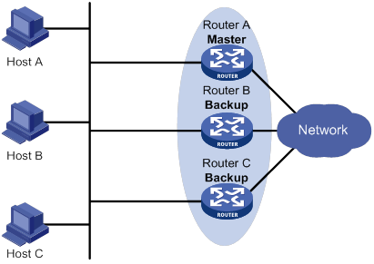
Assume that Router A is acting as the master to forward packets to external networks, and Router B and Router C are backups in listening state. When Router A fails, Router B and Router C elect a new master to forward packets for hosts on the subnet.
Load sharing
A router can join multiple VRRP groups. With different priorities in different VRRP groups, the router can act as the master in one VRRP group and a backup in another.
In load sharing mode, multiple VRRP groups provide gateway services. This mode requires a minimum of two VRRP groups, and each group has one master and multiple backups. The master roles in the VRRP groups are assumed by different routers, as shown in Figure 20.
Figure 20 Load sharing of VRRP
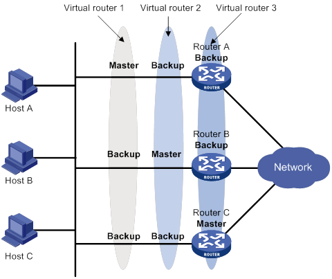
A router can be in multiple VRRP groups and have a different priority in each group.
As shown in Figure 20, the following VRRP groups exist:
· VRRP group 1—Router A is the master. Router B and Router C are the backups.
· VRRP group 2—Router B is the master. Router A and Router C are the backups.
· VRRP group 3—Router C is the master. Router A and Router B are the backups.
To implement load sharing among Router A, Router B, and Router C, perform the following tasks:
· Configure the virtual IP addresses of VRRP group 1, 2, and 3 as default gateway IP addresses for hosts on the subnet.
· Assign the highest priority to Router A, B, and C in VRRP group 1, 2, and 3, respectively.
VRRP load balancing mode
In a standard-mode VRRP group, only the master can forward packets and backups are in listening state. You can create multiple VRRP groups to share traffic, but you must configure different gateways for hosts on the subnet.
In load balancing mode, a VRRP group maps its virtual IP address to multiple virtual MAC addresses, assigning one virtual MAC address to each member router. Every router in this VRRP group can forward traffic and respond to IPv4 ARP requests or IPv6 ND requests from hosts. Because their virtual MAC addresses are different, traffic from hosts is distributed across the VRRP group members. Load balancing mode simplifies configuration and improves forwarding efficiency.
VRRP load balancing mode uses the same master election, preemption, and tracking mechanisms as the standard mode. New mechanisms have been introduced to VRRP load balancing mode, as described in the following sections.
Virtual MAC address assignment
In load balancing mode, the master assigns virtual MAC addresses to routers in the VRRP group. The master uses different MAC addresses to respond to ARP requests or ND requests from different hosts. The backup routers, however, do not answer ARP requests or ND requests from hosts.
In an IPv4 network, a load balanced VRRP group works as follows:
1. The master assigns virtual MAC addresses to all member routers, including itself. This example assumes that the virtual IP address of the VRRP group is 10.1.1.1/24, Router A is the master, and Router B is the backup. Router A assigns 000f-e2ff-0011 for itself and 000f-e2ff-0012 for Router B. See Figure 21.
Figure 21 Virtual MAC address assignment
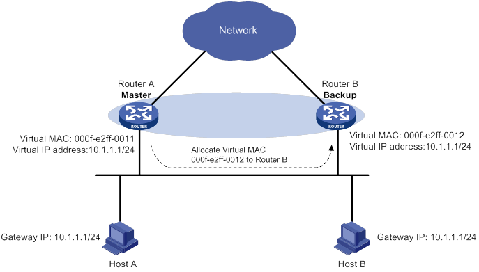
2. When an ARP request arrives, the master (Router A) selects a virtual MAC address based on the load balancing algorithm to answer the ARP request. In this example, Router A returns the virtual MAC address of itself in response to the ARP request from Host A. Router A returns the virtual MAC address of Router B in response to the ARP request from Host B. See Figure 22.
Figure 22 Answering ARP requests
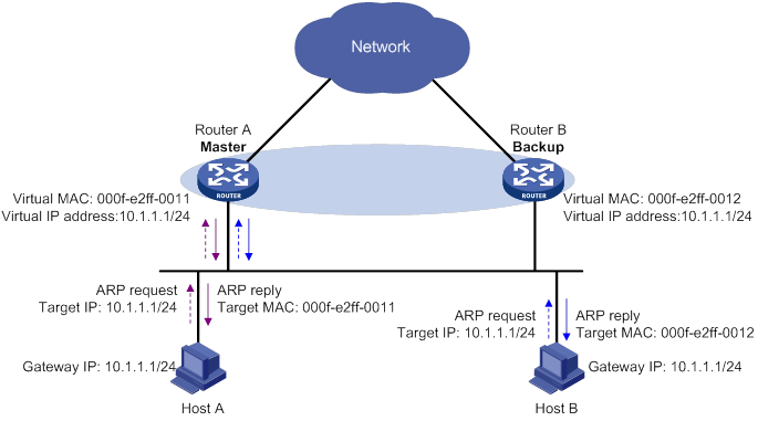
3. Each host sends packets to the returned MAC address. As shown in Figure 23, Host A sends packets to Router A and Host B sends packets to Router B.
Figure 23 Sending packets to different routers for forwarding
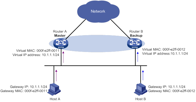
In the ARP reply sent by the master, the source MAC address in the Ethernet header is different from the sender MAC address in the message body. For the Layer 2 device to forward the ARP packet, follow these configuration guidelines on the Layer 2 device:
· Do not enable ARP packet source MAC address consistency check.
· Do not specify the src-mac keyword when you enable ARP packet validity check for ARP detection.
For more information about ARP packet source MAC address consistency check and ARP detection, see Security Configuration Guide.
Virtual forwarder
Virtual forwarder creation
Virtual MAC addresses enable traffic distribution across routers in a VRRP group. To enable routers in the VRRP group to forward packets, VFs must be created on them. Each VF is associated with a virtual MAC address in the VRRP group and forwards packets that are sent to this virtual MAC address.
VFs are created on routers in a VRRP group, as follows:
1. The master assigns virtual MAC addresses to all routers in the VRRP group. Each member router creates a VF for this MAC address and becomes the owner of this VF.
2. Each VF owner advertises its VF information to the other member routers.
3. After receiving the VF advertisement, each of the other routers creates the advertised VF.
Eventually, every member router maintains one VF for each virtual MAC address in the VRRP group.
VF weight and priority
The weight of a VF indicates the forwarding capability of a VF. A higher weight means higher forwarding capability. When the weight is lower than the lower limit of failure, the VF cannot forward packets.
The priority of a VF determines the VF state. Among the VFs created on different member routers for the same virtual MAC address, the VF with the highest priority is in active state. This VF, known as the active virtual forwarder (AVF), forwards packets. All other VFs listen to the state of the AVF and are known as the listening virtual forwarders (LVFs). VF priority is in the range of 0 to 255, where 255 is reserved for the VF owner. When the weight of a VF owner is higher than or equal to the lower limit of failure, the priority of the VF owner is 255.
The priority of a VF is calculated based on its weight.
· If the VF weight is higher than or equal to the lower limit of failure, the following VF priorities apply:
? On a VF owner, the VF priority is 255.
? On a non-VF owner, the VF priority is calculated as weight/(number of local AVFs + 1).
· If the VF weight is lower than the lower limit of failure, the VF priority is 0.
VF backup
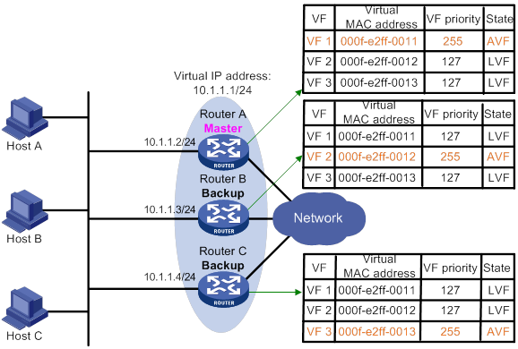
Figure 24 shows the VF table on each router in the VRRP group and how the VFs back up one another. The master, Router A, assigns virtual MAC addresses 000f-e2ff-0011, 000f-e2ff-0012, and 000f-e2ff-0013 to itself, Router B, and Router C, respectively. Each router creates VF 1, VF 2, and VF 3 for virtual MAC addresses 000f-e2ff-0011, 000f-e2ff-0012, and 000f-e2ff-0013, respectively. The VFs for the same virtual MAC address on different routers back up one another. For example, the VF 1 instances on Router A, Router B, and Router C back up one another.
· The VF 1 instances on Router B and Router C have a priority of 255/(1 + 1), or 127. Because their priorities are lower than the priority of the VF 1 instance on Router A, they act as LVFs. These LVFs listen to the state of the VF 1 instance on Router A.
· When the VF 1 instance on Router A fails, the VF 1 instances on Router B and Router C elect the one with higher priority as the new AVF. This AVF forwards packets destined for virtual MAC address 000f-e2ff-0011. If the two LVFs' priorities are the same, the LVF with a greater device MAC address becomes the new AVF.
A VF always operates in preemptive mode. When an LVF finds its priority value higher than the one advertised by the AVF, the LVF declares itself as the AVF.
VF timers
When the AVF on a router fails, the new AVF on another router creates the following timers for the failed AVF:
· Redirect timer—Before this timer expires, the master still uses the virtual MAC address corresponding to the failed AVF to respond to ARP/ND requests from hosts. The VF owner can share traffic load if the VF owner resumes normal operation within this time. When this timer expires, the master stops using the virtual MAC address corresponding to the failed AVF to respond to ARP/ND requests from hosts.
· Timeout timer—The duration after which the new AVF takes over responsibilities of the failed VF owner. Before this timer expires, all routers in the VRRP group keep the VFs that correspond to the failed AVF. The new AVF forwards packets destined for the virtual MAC address of the failed AVF. When this timer expires, all routers in the VRRP group remove the VFs that correspond to the failed AVF, including the new AVF. Packets destined for the virtual MAC address of the failed AVF are not forwarded any longer.
VF tracking
An AVF forwards packets destined for the MAC address of the AVF. If the AVF's upstream link fails but no LVF takes over, the hosts that use the AVF's MAC address as their gateway MAC address cannot access the external network.
The VF tracking function can solve this problem. You can use NQA or BFD to monitor the upstream link state of the VF owner, and associate the VFs with NQA or BFD through the tracking function. This enables the collaboration between VRRP and NQA or BFD through the Track module. When the upstream link fails, the state of the track entry changes to Negative. The weights of the VFs (including the AVF) on the router decrease by a specific value. The corresponding LVF with a higher priority on another router becomes the AVF and forwards packets.
Protocols and standards
· RFC 3768, Virtual Router Redundancy Protocol (VRRP)
· RFC 5798, Virtual Router Redundancy Protocol (VRRP) Version 3 for IPv4 and IPv6
Configuring IPv4 VRRP
VRRP cannot be configured on member ports of aggregation groups.
IPv4 VRRP configuration task list
|
Tasks at a glance |
Remarks |
|
(Required.) Specifying an IPv4 VRRP operating mode |
N/A |
|
(Optional.) Specifying the IPv4 VRRP version |
N/A |
|
(Required.) Creating a VRRP group and assigning a virtual IP address |
N/A |
|
(Optional.) Configuring the router priority, preemptive mode, and tracking function |
N/A |
|
N/A |
|
|
(Optional.) Configuring VF tracking |
This configuration applies only to VRRP load balancing mode. |
|
(Optional.) Enabling SNMP notifications for VRRP |
N/A |
|
(Optional.) Disabling an IPv4 VRRP group |
N/A |
Specifying an IPv4 VRRP operating mode
A VRRP group can operate in either of the following modes:
· Standard mode—Only the master can forward packets.
· Load balancing mode—All members that have an AVF can forward packets.
After an IPv4 VRRP operating mode is configured on a router, all IPv4 VRRP groups on the router operate in the specified operating mode.
To specify an IPv4 VRRP operating mode:
|
Step |
Command |
Remarks |
|
1. Enter system view. |
system-view |
N/A |
|
2. Specify an IPv4 VRRP operating mode. |
·
Specify the standard mode: ·
Specify the load balancing mode: |
By default, VRRP operates in standard mode. |
Specifying the IPv4 VRRP version
The VRRP version on all routers in an IPv4 VRRP group must be the same.
To specify the version of IPv4 VRRP:
|
Step |
Command |
Remarks |
|
1. Enter system view. |
system-view |
N/A |
|
2. Enter interface view. |
interface interface-type interface-number |
N/A |
|
3. Specify the version of VRRP. |
vrrp version version-number |
By default, VRRPv3 is used. |
Creating a VRRP group and assigning a virtual IP address
A VRRP group can operate correctly after you create it and assign a minimum of one virtual IP address to it. You can configure multiple virtual IP addresses for the VRRP group on an interface that connects to multiple subnets for router backup on different subnets.
Configuration guidelines
· An interface supports a maximum of 16 VRRP groups. A VRRP group supports a maximum of 16 virtual IP addresses.
· In VRRP load balancing mode, the device supports a maximum of MaxVRNum/N VRRP groups. MaxVRNum refers to the maximum number of VRRP groups supported by the device in VRRP standard mode. N refers to the number of devices in the VRRP group.
· When VRRP is operating in standard mode, the virtual IP address of a VRRP group can be either of the following addresses:
? Unused IP address on the subnet where the VRRP group resides.
? IP address of an interface on a router in the VRRP group.
· In load balancing mode, the virtual IP address of a VRRP group can be any unassigned IP address of the subnet where the VRRP group resides. It cannot be the IP address of any interface in the VRRP group. No IP address owner can exist in a VRRP group.
· On an IP address owner, as a best practice, do not use the network command to enable OSPF on the interface owning the virtual IP address of the VRRP group. For more information about the network command, see Layer 3—IP Routing Command Reference.
· If you create an IPv4 VRRP group without assigning virtual IP address to it, the VRRP group stays in inactive state and does not function.
· Removal of the VRRP group on the IP address owner causes IP address collision. To avoid the collision, change the IP address of the interface on the IP address owner before you remove the VRRP group from the interface.
· The virtual IP address of an IPv4 VRRP group and the downlink interface IP address of the VRRP group must be in the same subnet. Otherwise, the hosts in the subnet might fail to access external networks.
Configuration procedure
To create a VRRP group and assign a virtual IP address:
|
Step |
Command |
Remarks |
|
1. Enter system view. |
system-view |
N/A |
|
2. Enter interface view. |
interface interface-type interface-number |
N/A |
|
3. Create a VRRP group and assign a virtual IP address. |
vrrp vrid virtual-router-id virtual-ip virtual-address |
By default, no VRRP groups exist. |
Configuring the router priority, preemptive mode, and tracking function
The router priority determines which router in the VRRP group acts as the master. The preemptive mode enables a backup to take over as the master when it detects that it has a higher priority than the current master. The tracking function decreases the router priority or enables the backup to take over as the master when the state of the monitored track entry transits to Negative.
Configuration guidelines
· The running priority of an IP address owner is always 255, and you do not need to configure it. An IP address owner always operates in preemptive mode.
· If you configure the vrrp vrid track priority reduced or vrrp vrid track switchover command on an IP address owner, the configuration does not take effect until the router becomes a non-IP address owner.
Configuration procedure
To configure the router priority, preemptive mode, and tracking function:
|
Step |
Command |
Remarks |
|
1. Enter system view. |
system-view |
N/A |
|
2. Enter interface view. |
interface interface-type interface-number |
N/A |
|
3. Set the priority of the router in the VRRP group. |
vrrp vrid virtual-router-id priority priority-value |
The default setting is 100. |
|
4. Enable the preemptive mode for the router in a VRRP group and set the preemption delay time. |
vrrp vrid virtual-router-id preempt-mode [ delay delay-value ] |
By default, the router in a VRRP group operates in preemptive mode and the preemption delay time is 0 centiseconds, which means an immediate preemption. |
|
5. Associate a VRRP group with a track entry. |
vrrp vrid virtual-router-id track track-entry-number { forwarder-switchover member-ip ip-address | priority reduced [ priority-reduced ] | switchover | weight reduced [ weight-reduced ] } |
By default, a VRRP group is not associated with any track entry. |
Configuring IPv4 VRRP packet attributes
Configuration guidelines
· You can configure different authentication modes and authentication keys for VRRP groups on an interface. However, members of the same VRRP group must use the same authentication mode and authentication key.
· In VRRPv2, all routers in a VRRP group must have the same VRRP advertisement interval.
· In VRRPv3, authentication mode and authentication key settings do not take effect.
· In VRRPv3, routers in an IPv4 VRRP group can have different intervals for sending VRRP advertisements. The master in the VRRP group sends VRRP advertisements at specified intervals, and carries the interval in the advertisements. After a backup receives the advertisement, it records the interval in the advertisement. If the backup does not receive a VRRP advertisement before the timer (3 x recorded interval + Skew_Time) expires, it regards the master as failed and takes over.
Configuration procedure
To configure VRRP packet attributes:
|
Step |
Command |
Remarks |
|
1. Enter system view. |
system-view |
N/A |
|
2. Enter interface view. |
interface interface-type interface-number |
N/A |
|
3. Configure the authentication mode and authentication key for an IPv4 VRRP group to send and receive VRRP packets. |
vrrp vrid virtual-router-id authentication-mode { md5 | simple } { cipher | plain } string |
By default, authentication is disabled. |
|
4. Set the interval at which the master in an IPv4 VRRP group sends VRRP advertisements. |
vrrp vrid virtual-router-id timer advertise adver-interval |
The default setting is 100 centiseconds. As a best practice to maintain system stability, set the VRRP advertisement interval to be greater than 100 centiseconds. |
|
5. Specify the source interface for receiving and sending VRRP packets. |
vrrp vrid virtual-router-id source-interface interface-type interface-number |
By default, the source interface for receiving and sending VRRP packets is not specified. The interface where the VRRP group resides sends and receives VRRP packets. |
|
6. Enable TTL check for IPv4 VRRP packets. |
vrrp check-ttl enable |
By default, TTL check for IPv4 VRRP packets is enabled. |
|
7. Return to system view. |
quit |
N/A |
|
8. Set a DSCP value for VRRP packets. |
vrrp dscp dscp-value |
The DSCP value identifies the packet priority during transmission. By default, the DSCP value for VRRP packets is 48. |
Configuring VF tracking
You can configure VF tracking in both standard mode and load balancing mode, but the function takes effect only in load balancing mode.
In load balancing mode, you can establish the collaboration between the VFs and NQA or BFD through the tracking function. When the state of the track entry transits to Negative, the weights of all VFs in the VRRP group on the router decrease by a specific value. When the state of the track entry transits to Positive or Notready, the original weight values of the VFs restore.
Configuration guidelines
· By default, the weight of a VF is 255, and its lower limit of failure is 10.
· When the weight of a VF owner is higher than or equal to the lower limit of failure, its priority is always 255. The priority does not change with the weight. When the upstream link of the VF owner fails, an LVF must take over as the AVF. The switchover happens when the weight of the VF owner drops below the lower limit of failure. This requires that the reduced weight for the VF owner be higher than 245.
Configuration procedure
To configure VF tracking:
|
Step |
Command |
Remarks |
|
1. Enter system view. |
system-view |
N/A |
|
2. Enter interface view. |
interface interface-type interface-number |
N/A |
|
3. Configure the VFs in a VRRP group to monitor a track entry and configure the reduced weight. |
vrrp vrid virtual-router-id track track-entry-number { forwarder-switchover member-ip ip-address | priority reduced [ priority-reduced ] | switchover | weight reduced [ weight-reduced ] } |
By default, no track entry is specified. |
Enabling SNMP notifications for VRRP
Perform this task to enable VRRP to report important events through notifications to the SNMP module. The SNMP module determines how to output the notifications according to the configured output rules. For more information about notifications, see Network Management and Monitoring Configuration Guide.
To enable SNMP notifications for VRRP:
|
Step |
Command |
Remarks |
|
1. Enter system view. |
system-view |
N/A |
|
2. Enable SNMP notifications for VRRP. |
snmp-agent trap enable vrrp [ auth-failure | new-master ] |
By default, SNMP notifications for VRRP are enabled. |
Disabling an IPv4 VRRP group
You can temporarily disable an IPv4 VRRP group. After being disabled, the VRRP group stays in initialized state, and its configurations remain unchanged. You can change the configuration of a VRRP group when the VRRP group is disabled. Your changes take effect when you enable the VRRP group again.
To disable an IPv4 VRRP group:
|
Step |
Command |
Remarks |
|
1. Enter system view. |
system-view |
N/A |
|
2. Enter interface view. |
interface interface-type interface-number |
N/A |
|
3. Disable a VRRP group. |
vrrp vrid virtual-router-id shutdown |
By default, a VRRP group is enabled. |
Displaying and maintaining IPv4 VRRP
Execute display commands in any view and the reset command in user view.
|
Task |
Command |
|
Display states of IPv4 VRRP groups. |
display vrrp [ interface interface-type interface-number [ vrid virtual-router-id ] ] [ verbose ] |
|
Display statistics for IPv4 VRRP groups. |
display vrrp statistics [ interface interface-type interface-number [ vrid virtual-router-id ] ] |
|
Clear statistics for IPv4 VRRP groups. |
reset vrrp statistics [ interface interface-type interface-number [ vrid virtual-router-id ] ] |
Configuring IPv6 VRRP
This section describes how to configure IPv6 VRRP.
IPv6 VRRP configuration task list
|
Tasks at a glance |
Remarks |
|
(Required.) Specifying an IPv6 VRRP operating mode |
N/A |
|
(Required.) Creating a VRRP group and assigning a virtual IPv6 address |
N/A |
|
(Optional.) Configuring the router priority, preemptive mode, and tracking function |
N/A |
|
(Optional.) Configuring VF tracking |
This configuration applies only to VRRP load balancing mode. |
|
(Optional.) Configuring IPv6 VRRP packet attributes |
N/A |
|
(Optional.) Disabling an IPv6 VRRP group |
N/A |
Specifying an IPv6 VRRP operating mode
A VRRP group can operate in either of the following modes:
· Standard mode—Only the master can forward packets.
· Load balancing mode—All members that have an AVF can forward packets.
After the IPv6 VRRP operating mode is specified on a router, all IPv6 VRRP groups on the router operate in the specified operating mode.
To specify an IPv6 VRRP operating mode:
|
Step |
Command |
Remarks |
|
1. Enter system view. |
system-view |
N/A |
|
2. Specify an IPv6 VRRP operating mode. |
·
Specify the standard mode: ·
Specify the load balancing mode: |
By default, VRRP operates in standard mode. |
Creating a VRRP group and assigning a virtual IPv6 address
Configuration guidelines
· On an IP address owner, as a best practice, do not use the ospfv3 area command to enable OSPF on the interface owning the virtual IPv6 address of the VRRP group. For more information about the ospfv3 area command, see Layer 3—IP Routing Command Reference.
· In load balancing mode, the virtual IPv6 address of a VRRP group cannot be the same as the IPv6 address of any interface in the VRRP group.
· An interface supports a maximum of 16 VRRP groups. A VRRP group supports a maximum of 16 virtual IPv6 addresses.
· In VRRP load balancing mode, the device supports a maximum of MaxVRNum/N VRRP groups. MaxVRNum refers to the maximum number of VRRP groups supported by the device in VRRP standard mode. N refers to the number of devices in the VRRP group.
· If you create an IPv6 VRRP group without assigning virtual IPv6 address to it, the VRRP group stays in inactive state and does not function.
· Removal of the VRRP group on the IP address owner causes IP address collision. To avoid the collision, change the IPv6 address of the interface on the IP address owner before you remove the VRRP group from the interface.
· The virtual IPv6 address of an IPv6 VRRP group and the downlink interface IPv6 address of the VRRP group must be in the same subnet. Otherwise, the hosts in the subnet might fail to access external networks.
Configuration procedure
To create a VRRP group and assign a virtual IPv6 address:
|
Step |
Command |
Remarks |
|
1. Enter system view. |
system-view |
N/A |
|
2. Enter interface view. |
interface interface-type interface-number |
N/A |
|
3. Create a VRRP group and assign a virtual IPv6 address, which is a link-local address. |
vrrp ipv6 vrid virtual-router-id virtual-ip virtual-address link-local |
By default, no VRRP groups exist. The first virtual IPv6 address that you assign to an IPv6 VRRP group must be a link-local address. It must be the last address you remove. Only one link local address is allowed in a VRRP group. |
|
4. (Optional.) Assign a virtual IPv6 address, which is a global unicast address. |
vrrp ipv6 vrid virtual-router-id virtual-ip virtual-address |
By default, no global unicast address is assigned for an IPv6 VRRP group. |
Configuring the router priority, preemptive mode, and tracking function
Configuration guidelines
· The running priority of an IP address owner is always 255, and you do not need to configure it. An IP address owner always operates in preemptive mode.
· If you configure the vrrp ipv6 vrid track priority reduced or vrrp ipv6 vrid track switchover command on an IP address owner, the configuration does not take effect until the router becomes a non-IP address owner.
· When the track entry changes from Negative to Positive or Notready, the router automatically restores its priority or the failed master router becomes the master again.
Configuration procedure
To configure the router priority, preemptive mode, and tracking function:
|
Step |
Command |
Remarks |
|
1. Enter system view. |
system-view |
N/A |
|
2. Enter interface view. |
interface interface-type interface-number |
N/A |
|
3. Set the priority of the router in the VRRP group. |
vrrp ipv6 vrid virtual-router-id priority priority-value |
The default setting is 100. |
|
4. Enable the preemptive mode for the router in a VRRP group and set the preemption delay time. |
vrrp ipv6 vrid virtual-router-id preempt-mode [ delay delay-value ] |
By default, the router in a VRRP group operates in preemptive mode and the preemption delay time is 0 centiseconds, which means an immediate preemption. |
|
5. Associate a VRRP group with a track entry. |
vrrp ipv6 vrid virtual-router-id track track-entry-number { forwarder-switchover member-ip ipv6-address | priority reduced [ priority-reduced ] | switchover | weight reduced [ weight-reduced ] } |
By default, a VRRP group is not associated with any track entry. |
Configuring VF tracking
You can configure VF tracking in both standard mode and load balancing mode, but the function takes effect only in load balancing mode.
In load balancing mode, you can configure the VFs in a VRRP group to monitor a track entry. When the state of the track entry transits to Negative, the weights of all VFs in the VRRP group on the router decrease by a specific value. When the state of the track entry transits to Positive or Notready, the original weights of the VFs restore.
Configuration guidelines
· By default, the weight of a VF is 255, and its lower limit of failure is 10.
· When the weight of a VF owner is higher than or equal to the lower limit of failure, its priority is always 255. The priority does not change with the weight. When the upstream link of the VF owner fails, an LVF must take over as the AVF. The switchover happens when the weight of the VF owner drops below the lower limit of failure. This requires that the reduced weight for the VF owner be higher than 245.
Configuration procedure
To configure VF tracking:
|
Step |
Command |
Remarks |
|
1. Enter system view. |
system-view |
N/A |
|
2. Enter interface view. |
interface interface-type interface-number |
N/A |
|
3. Configure the VFs in a VRRP group to monitor a track entry and configure the reduced weight. |
vrrp ipv6 vrid virtual-router-id track track-entry-number { forwarder-switchover member-ip ipv6-address | priority reduced [ priority-reduced ] | switchover | weight reduced [ weight-reduced ] } |
By default, no track entry is specified. |
Configuring IPv6 VRRP packet attributes
This section describes how to configure IPv6 VRRP packet attributes.
Configuration guidelines
· The routers in an IPv6 VRRP group can have different intervals for sending VRRP advertisements. The master in the VRRP group sends VRRP advertisements at the specified interval and carries the interval attribute in the advertisements. After a backup receives the advertisement, it records the interval in the advertisement. If the backup does not receive a VRRP advertisement before the timer (3 x recorded interval + Skew_Time) expires, it regards the master as failed and takes over.
· A high volume of network traffic might cause a backup to fail to receive VRRP advertisements from the master within the specified time. As a result, an unexpected master switchover occurs. To solve this problem, configure a larger interval.
Configuration procedure
To configure the IPv6 VRRP packet attribute:
|
Step |
Command |
Remarks |
|
1. Enter system view. |
system-view |
N/A |
|
2. Enter interface view. |
interface interface-type interface-number |
N/A |
|
3. Set the IPv6 VRRP advertisement interval. |
vrrp ipv6 vrid virtual-router-id timer advertise adver-interval |
The default setting is 100 centiseconds. As a best practice to maintain system stability, set the VRRP advertisement interval to be greater than 100 centiseconds. |
|
4. Return to system view. |
quit |
N/A |
|
5. Set a DSCP value for IPv6 VRRP packets. |
vrrp ipv6 dscp dscp-value |
The DSCP value identifies the packet priority during transmission. By default, the DSCP value for IPv6 VRRP packets is 56. |
Disabling an IPv6 VRRP group
You can temporarily disable an IPv6 VRRP group. After being disabled, the VRRP group stays in initialized state, and its configurations remain unchanged. You can change the configuration of a VRRP group when it is disabled. Your changes take effect when you enable the VRRP group again.
To disable an IPv6 VRRP group:
|
Step |
Command |
Remarks |
|
1. Enter system view. |
system-view |
N/A |
|
2. Enter interface view. |
interface interface-type interface-number |
N/A |
|
3. Disable an IPv6 VRRP group. |
vrrp ipv6 vrid virtual-router-id shutdown |
By default, an IPv6 VRRP group is enabled. |
Displaying and maintaining IPv6 VRRP
Execute display commands in any view and the reset command in user view.
|
Task |
Command |
|
Display the states of IPv6 VRRP groups. |
display vrrp ipv6 [ interface interface-type interface-number [ vrid virtual-router-id ] ] [ verbose ] |
|
Display statistics for IPv6 VRRP groups. |
display vrrp ipv6 statistics [ interface interface-type interface-number [ vrid virtual-router-id ] ] |
|
Clear statistics for IPv6 VRRP groups. |
reset vrrp ipv6 statistics [ interface interface-type interface-number [ vrid virtual-router-id ] ] |
IPv4 VRRP configuration examples
Single VRRP group configuration example
Network requirements
As shown in Figure 25, Router A and Router B form a VRRP group. They use the virtual IP address 10.1.1.111/24 to provide gateway service for the subnet where Host A resides.
Router A operates as the master to forward packets from Host A to Host B. When Router A fails, Router B takes over to forward packets for Host A.
Configure Router A to operate in preempt mode so Router A can forward traffic as long as Router A operates correctly. Set the preemption delay to 5000 centiseconds to avoid frequent status change.
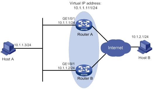
Configuration procedure
1. Configure Router A:
# Specify an IP address for Router A.
<RouterA> system-view
[RouterA] interface gigabitethernet 1/0/1
[RouterA-GigabitEthernet1/0/1] ip address 10.1.1.1 255.255.255.0
# Create VRRP group 1 on GigabitEthernet 1/0/1 and set its virtual IP address to 10.1.1.111.
[RouterA-GigabitEthernet1/0/1] vrrp vrid 1 virtual-ip 10.1.1.111
# Assign Router A a higher priority than Router B in VRRP group 1, so Router A can become the master.
[RouterA-GigabitEthernet1/0/1] vrrp vrid 1 priority 110
# Configure Router A to operate in preemptive mode, so it can become the master whenever it operates correctly. Set the preemption delay to 5000 centiseconds to avoid frequent status switchover.
[RouterA-GigabitEthernet1/0/1] vrrp vrid 1 preempt-mode delay 5000
2. Configure Router B:
# Specify an IP address for Router A.
<RouterB> system-view
[RouterB] interface gigabitethernet 1/0/1
[RouterB-GigabitEthernet1/0/1] ip address 10.1.1.2 255.255.255.0
# Create VRRP group 1 on GigabitEthernet 1/0/1 and set its virtual IP address to 10.1.1.111.
[RouterB-GigabitEthernet1/0/1] vrrp vrid 1 virtual-ip 10.1.1.111
# Set the priority of Router B to 100 in VRRP group 1.
[RouterB-GigabitEthernet1/0/1] vrrp vrid 1 priority 100
# Configure Router B to operate in preemptive mode, and set the preemption delay to 5000 centiseconds.
[RouterB-GigabitEthernet1/0/1] vrrp vrid 1 preempt-mode delay 5000
Verifying the configuration
# Ping Host B from Host A. (Details not shown.)
# Display detailed information about VRRP group 1 on Router A.
[RouterA-GigabitEthernet1/0/1] display vrrp verbose
IPv4 Virtual Router Information:
Running Mode : Standard
Total number of virtual routers : 1
Interface GigabitEthernet1/0/1
VRID : 1 Adver Timer : 100
Admin Status : Up State : Master
Config Pri : 110 Running Pri : 110
Preempt Mode : Yes Delay Time : 5000
Auth Type : None
Virtual IP : 10.1.1.111
Virtual MAC : 0000-5e00-0101
Master IP : 10.1.1.1
# Display detailed information about VRRP group 1 on Router B.
[RouterB-GigabitEthernet1/0/1] display vrrp verbose
IPv4 Virtual Router Information:
Running Mode : Standard
Total number of virtual routers : 1
Interface GigabitEthernet1/0/1
VRID : 1 Adver Timer : 100
Admin Status : Up State : Backup
Config Pri : 100 Running Pri : 100
Preempt Mode : Yes Delay Time : 5000
Become Master : 412ms left
Auth Type : None
Virtual IP : 10.1.1.111
Master IP : 10.1.1.1
The output shows that Router A is operating as the master in VRRP group 1 to forward packets from Host A to Host B.
# Disconnect the link between Host A and Router A, and verify that Host A can still ping Host B. (Details not shown.)
# Display detailed information about VRRP group 1 on Router B.
[RouterB-GigabitEthernet1/0/1] display vrrp verbose
IPv4 Virtual Router Information:
Running Mode : Standard
Total number of virtual routers : 1
Interface GigabitEthernet1/0/1
VRID : 1 Adver Timer : 100
Admin Status : Up State : Master
Config Pri : 100 Running Pri : 100
Preempt Mode : Yes Delay Time : 5000
Auth Type : None
Virtual IP : 10.1.1.111
Virtual MAC : 0000-5e00-0101
Master IP : 10.1.1.2
The output shows that when Router A fails, Router B takes over to forward packets from Host A to Host B.
# Recover the link between Host A and Router A, and display detailed information about VRRP group 1 on Router A.
[RouterA-GigabitEthernet1/0/1] display vrrp verbose
IPv4 Virtual Router Information:
Running Mode : Standard
Total number of virtual routers : 1
Interface GigabitEthernet1/0/1
VRID : 1 Adver Timer : 100
Admin Status : Up State : Master
Config Pri : 110 Running Pri : 110
Preempt Mode : Yes Delay Time : 5000
Auth Type : None
Virtual IP : 10.1.1.111
Virtual MAC : 0000-5e00-0101
Master IP : 10.1.1.1
The output shows that after Router A resumes normal operation, it becomes the master to forward packets from Host A to Host B.
Multiple VRRP groups configuration example
To implement load sharing between the VRRP groups, manually configure the default gateway 10.1.1.111 for some hosts and 10.1.1.112 for the other on the subnet 10.1.1.0/24.
Network requirements
As shown in Figure 26, Router A and Router B form two VRRP groups to implement load sharing and mutual backup. VRRP group 1 uses the virtual IP address 10.1.1.111/24 to provide gateway service for some hosts on the subnet 10.1.1.0/24. VRRP group 2 uses the virtual IP address 10.1.1.112/24 to provide gateway service for the other hosts on the subnet.
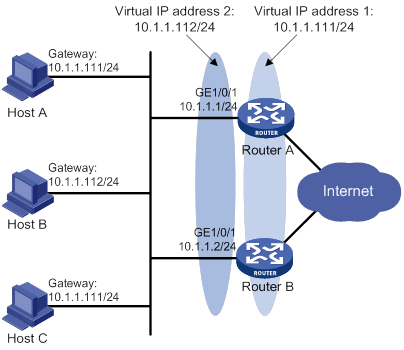
Configuration procedure
1. Configure Router A:
# Specify an IP address for Router A.
<RouterA> system-view
[RouterA] interface gigabitethernet 1/0/1
[RouterA-GigabitEthernet1/0/1] ip address 10.1.1.1 255.255.255.0
# Create VRRP group 1 and set its virtual IP address to 10.1.1.111.
[RouterA-GigabitEthernet1/0/1] vrrp vrid 1 virtual-ip 10.1.1.111
# Assign Router A a higher priority than Router B in VRRP group 1, so Router A can become the master in the group.
[RouterA-GigabitEthernet1/0/1] vrrp vrid 1 priority 110
# Create VRRP group 2, and set its virtual IP address to 10.1.1.112.
[RouterA-GigabitEthernet1/0/1] vrrp vrid 2 virtual-ip 10.1.1.112
2. Configure Router B:
# Specify an IP address for Router B.
<RouterB> system-view
[RouterB] interface gigabitethernet 1/0/1
[RouterB-GigabitEthernet1/0/1] ip address 10.1.1.2 255.255.255.0
# Create VRRP group 1, and set its virtual IP address to 10.1.1.111.
[RouterB-GigabitEthernet1/0/1] vrrp vrid 1 virtual-ip 10.1.1.111
# Create VRRP group 2, and set its virtual IP address to 10.1.1.112.
[RouterB-GigabitEthernet1/0/1] vrrp vrid 2 virtual-ip 10.1.1.112
# Assign Router B a higher priority than Router A in VRRP group 2, so Router B can become the master in the group.
[RouterB-GigabitEthernet1/0/1] vrrp vrid 2 priority 110
Verifying the configuration
# Display detailed information about the VRRP groups on Router A.
[RouterA-GigabitEthernet1/0/1] display vrrp verbose
IPv4 Virtual Router Information:
Running Mode : Standard
Total number of virtual routers : 2
Interface GigabitEthernet1/0/1
VRID : 1 Adver Timer : 100
Admin Status : Up State : Master
Config Pri : 110 Running Pri : 110
Preempt Mode : Yes Delay Time : 0
Auth Type : None
Virtual IP : 10.1.1.111
Virtual MAC : 0000-5e00-0101
Master IP : 10.1.1.1
Interface GigabitEthernet1/0/1
VRID : 2 Adver Timer : 100
Admin Status : Up State : Backup
Config Pri : 100 Running Pri : 100
Preempt Mode : Yes Delay Time : 0
Become Master : 201ms left
Auth Type : None
Virtual IP : 10.1.1.112
Master IP : 10.1.1.2
# Display detailed information about the VRRP groups on Router B.
[RouterB-GigabitEthernet1/0/1] display vrrp verbose
IPv4 Virtual Router Information:
Running Mode : Standard
Total number of virtual routers : 2
Interface GigabitEthernet1/0/1
VRID : 1 Adver Timer : 100
Admin Status : Up State : Backup
Config Pri : 100 Running Pri : 100
Preempt Mode : Yes Delay Time : 0
Become Master : 185ms left
Auth Type : None
Virtual IP : 10.1.1.111
Master IP : 10.1.1.1
Interface GigabitEthernet1/0/1
VRID : 2 Adver Timer : 100
Admin Status : Up State : Master
Config Pri : 110 Running Pri : 110
Preempt Mode : Yes Delay Time : 0
Auth Type : None
Virtual IP : 10.1.1.112
Virtual MAC : 0000-5e00-0102
Master IP : 10.1.1.2
The output shows the following information:
· Router A is operating as the master in VRRP group 1 to forward Internet traffic for hosts that use the default gateway 10.1.1.111/24.
· Router B is operating as the master in VRRP group 2 to forward Internet traffic for hosts that use the default gateway 10.1.1.112/24.
VRRP load balancing configuration example
Network requirements
As shown in Figure 27, Router A, Router B, and Router C form a load-balanced VRRP group. They use the virtual IP address 10.1.1.1/24 to provide gateway service for subnet 10.1.1.0/24.
Configure VFs on Router A, Router B, and Router C to monitor their respective GigabitEthernet 1/0/2. When the interface on any one of them fails, the weights of the VFs on the problematic router decrease so another AVF can take over.
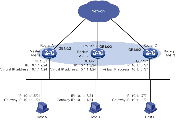
Configuration procedure
1. Configure Router A:
# Configure VRRP to operate in load balancing mode.
<RouterA> system-view
[RouterA] vrrp mode load-balance
# Create VRRP group 1, and set its virtual IP address to 10.1.1.1.
[RouterA] interface gigabitethernet 1/0/1
[RouterA-GigabitEthernet1/0/1] ip address 10.1.1.2 24
[RouterA-GigabitEthernet1/0/1] vrrp vrid 1 virtual-ip 10.1.1.1
# Assign Router A the highest priority in VRRP group 1, so Router A can become the master.
[RouterA-GigabitEthernet1/0/1] vrrp vrid 1 priority 120
# Configure Router A to operate in preemptive mode, so it can become the master whenever it operates correctly. Set the preemption delay to 5000 centiseconds to avoid frequent status switchover.
[RouterA-GigabitEthernet1/0/1] vrrp vrid 1 preempt-mode delay 5000
[RouterA-GigabitEthernet1/0/1] quit
# Create track entry 1 to monitor the upstream link status of GigabitEthernet 1/0/2. When the upstream link fails, the track entry transits to Negative.
[RouterA] track 1 interface gigabitethernet 1/0/2
# Configure the VFs in VRRP group 1 to monitor track entry 1, and decrease their weights by 250 when the track entry transits to Negative.
[RouterA] interface gigabitethernet 1/0/1
[RouterA-GigabitEthernet1/0/1] vrrp vrid 1 track 1 weight reduced 250
2. Configure Router B:
# Configure VRRP to operate in load balancing mode.
<RouterB> system-view
[RouterB] vrrp mode load-balance
# Create VRRP group 1, and set its virtual IP address to 10.1.1.1.
[RouterB] interface gigabitethernet 1/0/1
[RouterB-GigabitEthernet1/0/1] ip address 10.1.1.3 24
[RouterB-GigabitEthernet1/0/1] vrrp vrid 1 virtual-ip 10.1.1.1
# Assign Router B a higher priority than Router C in VRRP group 1, so Router B can become the master when Router A fails.
[RouterB-GigabitEthernet1/0/1] vrrp vrid 1 priority 110
# Configure Router B to operate in preemptive mode, and set the preemption delay to 5000 centiseconds.
[RouterB-GigabitEthernet1/0/1] vrrp vrid 1 preempt-mode delay 5000
[RouterB-GigabitEthernet1/0/1] quit
# Create track entry 1 to monitor the upstream link status of GigabitEthernet 1/0/2. When the upstream link fails, the track entry transits to Negative.
[RouterB] track 1 interface gigabitethernet 1/0/2
# Configure the VFs in VRRP group 1 to monitor track entry 1, and decrease their weights by 250 when the track entry transits to Negative.
[RouterB] interface gigabitethernet 1/0/1
[RouterB-GigabitEthernet1/0/1] vrrp vrid 1 track 1 weight reduced 250
3. Configure Router C:
# Configure VRRP to operate in load balancing mode.
<RouterC> system-view
[RouterC] vrrp mode load-balance
# Create VRRP group 1, and set its virtual IP address as 10.1.1.1.
[RouterC] interface gigabitethernet 1/0/1
[RouterC-GigabitEthernet1/0/1] ip address 10.1.1.4 24
[RouterC-GigabitEthernet1/0/1] vrrp vrid 1 virtual-ip 10.1.1.1
# Configure Router C to operate in preemptive mode, and set the preemption delay to 5000 centiseconds.
[RouterC-GigabitEthernet1/0/1] vrrp vrid 1 preempt-mode delay 5000
[RouterC-GigabitEthernet1/0/1] quit
# Create track entry 1 to monitor the upstream link status of GigabitEthernet 1/0/2. When the upstream link fails, the track entry transits to Negative.
[RouterC] track 1 interface gigabitethernet 1/0/2
# Configure the VFs in VRRP group 1 to monitor track entry 1, and decrease their weights by 250 when the track entry transits to Negative.
[RouterC] interface gigabitethernet 1/0/1
[RouterC-GigabitEthernet1/0/1] vrrp vrid 1 track 1 weight reduced 250
Verifying the configuration
# Verify that Host A can ping the external network. (Details not shown.)
# Display detailed information about VRRP group 1 on Router A.
[RouterA-GigabitEthernet1/0/1] display vrrp verbose
IPv4 Virtual Router Information:
Running Mode : Load Balance
Total number of virtual routers : 1
Interface GigabitEthernet1/0/1
VRID : 1 Adver Timer : 100
Admin Status : Up State : Master
Config Pri : 120 Running Pri : 120
Preempt Mode : Yes Delay Time : 5000
Auth Type : None
Virtual IP : 10.1.1.1
Member IP List : 10.1.1.2 (Local, Master)
10.1.1.3 (Backup)
10.1.1.4 (Backup)
Forwarder Information: 3 Forwarders 1 Active
Config Weight : 255
Running Weight : 255
Forwarder 01
State : Active
Virtual MAC : 000f-e2ff-0011 (Owner)
Owner ID : 0000-5e01-1101
Priority : 255
Active : local
Forwarder 02
State : Listening
Virtual MAC : 000f-e2ff-0012 (Learnt)
Owner ID : 0000-5e01-1103
Priority : 127
Active : 10.1.1.3
Forwarder 03
State : Listening
Virtual MAC : 000f-e2ff-0013 (Learnt)
Owner ID : 0000-5e01-1105
Priority : 127
Active : 10.1.1.4
Forwarder Weight Track Information:
Track Object : 1 State : Positive Weight Reduced : 250
# Display detailed information about VRRP group 1 on Router B.
[RouterB-GigabitEthernet1/0/1] display vrrp verbose
IPv4 Virtual Router Information:
Running Mode : Load Balance
Total number of virtual routers : 1
Interface GigabitEthernet1/0/1
VRID : 1 Adver Timer : 100
Admin Status : Up State : Backup
Config Pri : 110 Running Pri : 110
Preempt Mode : Yes Delay Time : 5000
Become Master : 426ms left
Auth Type : None
Virtual IP : 10.1.1.1
Member IP List : 10.1.1.3 (Local, Backup)
10.1.1.2 (Master)
10.1.1.4 (Backup)
Forwarder Information: 3 Forwarders 1 Active
Config Weight : 255
Running Weight : 255
Forwarder 01
State : Listening
Virtual MAC : 000f-e2ff-0011 (Learnt)
Owner ID : 0000-5e01-1101
Priority : 127
Active : 10.1.1.2
Forwarder 02
State : Active
Virtual MAC : 000f-e2ff-0012 (Owner)
Owner ID : 0000-5e01-1103
Priority : 255
Active : local
Forwarder 03
State : Listening
Virtual MAC : 000f-e2ff-0013 (Learnt)
Owner ID : 0000-5e01-1105
Priority : 127
Active : 10.1.1.4
Forwarder Weight Track Information:
Track Object : 1 State : Positive Weight Reduced : 250
# Display detailed information about VRRP group 1 on Router C.
[RouterC-GigabitEthernet1/0/1] display vrrp verbose
IPv4 Virtual Router Information:
Running Mode : Load Balance
Total number of virtual routers : 1
Interface GigabitEthernet1/0/1
VRID : 1 Adver Timer : 100
Admin Status : Up State : Backup
Config Pri : 100 Running Pri : 100
Preempt Mode : Yes Delay Time : 5000
Become Master : 417ms left
Auth Type : None
Virtual IP : 10.1.1.1
Member IP List : 10.1.1.4 (Local, Backup)
10.1.1.2 (Master)
10.1.1.3 (Backup)
Forwarder Information: 3 Forwarders 1 Active
Config Weight : 255
Running Weight : 255
Forwarder 01
State : Listening
Virtual MAC : 000f-e2ff-0011 (Learnt)
Owner ID : 0000-5e01-1101
Priority : 127
Active : 10.1.1.2
Forwarder 02
State : Listening
Virtual MAC : 000f-e2ff-0012 (Learnt)
Owner ID : 0000-5e01-1103
Priority : 127
Active : 10.1.1.3
Forwarder 03
State : Active
Virtual MAC : 000f-e2ff-0013 (Owner)
Owner ID : 0000-5e01-1105
Priority : 255
Active : local
Forwarder Weight Track Information:
Track Object : 1 State : Positive Weight Reduced : 250
The output shows that Router A is the master in VRRP group 1, and each of the three routers has one AVF and two LVFs.
# Disconnect the link of GigabitEthernet 1/0/2 on Router A, and display detailed information about VRRP group 1 on Router A.
[RouterA-GigabitEthernet1/0/1] display vrrp verbose
IPv4 Virtual Router Information:
Running Mode : Load Balance
Total number of virtual routers : 1
Interface GigabitEthernet1/0/1
VRID : 1 Adver Timer : 100
Admin Status : Up State : Master
Config Pri : 120 Running Pri : 120
Preempt Mode : Yes Delay Time : 5000
Auth Type : None
Virtual IP : 10.1.1.1
Member IP List : 10.1.1.2 (Local, Master)
10.1.1.3 (Backup)
10.1.1.4 (Backup)
Forwarder Information: 3 Forwarders 0 Active
Config Weight : 255
Running Weight : 5
Forwarder 01
State : Initialize
Virtual MAC : 000f-e2ff-0011 (Owner)
Owner ID : 0000-5e01-1101
Priority : 0
Active : 10.1.1.4
Forwarder 02
State : Initialize
Virtual MAC : 000f-e2ff-0012 (Learnt)
Owner ID : 0000-5e01-1103
Priority : 0
Active : 10.1.1.3
Forwarder 03
State : Initialize
Virtual MAC : 000f-e2ff-0013 (Learnt)
Owner ID : 0000-5e01-1105
Priority : 0
Active : 10.1.1.4
Forwarder Weight Track Information:
Track Object : 1 State : Negative Weight Reduced : 250
# Display detailed information about VRRP group 1 on Router C.
[RouterC-GigabitEthernet1/0/1] display vrrp verbose
IPv4 Virtual Router Information:
Running Mode : Load Balance
Total number of virtual routers : 1
Interface GigabitEthernet1/0/1
VRID : 1 Adver Timer : 100
Admin Status : Up State : Backup
Config Pri : 100 Running Pri : 100
Preempt Mode : Yes Delay Time : 5000
Become Master : 412ms left
Auth Type : None
Virtual IP : 10.1.1.1
Member IP List : 10.1.1.4 (Local, Backup)
10.1.1.2 (Master)
10.1.1.3 (Backup)
Forwarder Information: 3 Forwarders 2 Active
Config Weight : 255
Running Weight : 255
Forwarder 01
State : Active
Virtual MAC : 000f-e2ff-0011 (Take Over)
Owner ID : 0000-5e01-1101
Priority : 85
Active : local
Forwarder 02
State : Listening
Virtual MAC : 000f-e2ff-0012 (Learnt)
Owner ID : 0000-5e01-1103
Priority : 85
Active : 10.1.1.3
Forwarder 03
State : Active
Virtual MAC : 000f-e2ff-0013 (Owner)
Owner ID : 0000-5e01-1105
Priority : 255
Active : local
Forwarder Weight Track Information:
Track Object : 1 State : Positive Weight Reduced : 250
The output shows that when GigabitEthernet 1/0/2 on Router A fails, the weights of the VFs on Router A drop below the lower limit of failure. All VFs on Router A transit to the Initialized state and cannot forward traffic. The VF for MAC address 000f-e2ff-0011 on Router C becomes the AVF to forward traffic.
# When the timeout timer (about 1800 seconds) expires, display detailed information about VRRP group 1 on Router C.
[RouterC-GigabitEthernet1/0/1] display vrrp verbose
IPv4 Virtual Router Information:
Running Mode : Load Balance
Total number of virtual routers : 1
Interface GigabitEthernet1/0/1
VRID : 1 Adver Timer : 100
Admin Status : Up State : Backup
Config Pri : 100 Running Pri : 100
Preempt Mode : Yes Delay Time : 5000
Auth Type : None
Virtual IP : 10.1.1.1
Member IP List : 10.1.1.4 (Local, Backup)
10.1.1.2 (Master)
10.1.1.3 (Backup)
Forwarder Information: 2 Forwarders 1 Active
Config Weight : 255
Running Weight : 255
Forwarder 02
State : Listening
Virtual MAC : 000f-e2ff-0012 (Learnt)
Owner ID : 0000-5e01-1103
Priority : 127
Active : 10.1.1.3
Forwarder 03
State : Active
Virtual MAC : 000f-e2ff-0013 (Owner)
Owner ID : 0000-5e01-1105
Priority : 255
Active : local
Forwarder Weight Track Information:
Track Object : 1 State : Positive Weight Reduced : 250
The output shows that when the timeout timer expires, the VF for virtual MAC address 000f-e2ff-0011 is removed. The VF no longer forwards the packets destined for the MAC address.
# When Router A fails, display detailed information about VRRP group 1 on Router B.
[RouterB-GigabitEthernet1/0/1] display vrrp verbose
IPv4 Virtual Router Information:
Running Mode : Load Balance
Total number of virtual routers : 1
Interface GigabitEthernet1/0/1
VRID : 1 Adver Timer : 100
Admin Status : Up State : Master
Config Pri : 110 Running Pri : 110
Preempt Mode : Yes Delay Time : 5000
Auth Type : None
Virtual IP : 10.1.1.1
Member IP List : 10.1.1.3 (Local, Master)
10.1.1.4 (Backup)
Forwarder Information: 2 Forwarders 1 Active
Config Weight : 255
Running Weight : 255
Forwarder 02
State : Active
Virtual MAC : 000f-e2ff-0012 (Owner)
Owner ID : 0000-5e01-1103
Priority : 255
Active : local
Forwarder 03
State : Listening
Virtual MAC : 000f-e2ff-0013 (Learnt)
Owner ID : 0000-5e01-1105
Priority : 127
Active : 10.1.1.4
Forwarder Weight Track Information:
Track Object : 1 State : Positive Weight Reduced : 250
The output shows the following information:
· When Router A fails, Router B becomes the master because it has a higher priority than Router C.
· The VF for virtual MAC address 000f-e2ff-0011 is removed.
IPv6 VRRP configuration examples
Single VRRP group configuration example
Network requirements
As shown in Figure 28, Router A and Router B form a VRRP group. They use the virtual IP addresses 1::10/64 and FE80::10 to provide gateway service for the subnet where Host A resides.
Host A learns 1::10/64 as its default gateway from RA messages sent by the routers.
Router A operates as the master to forward packets from Host A to Host B. When Router A fails, Router B takes over to forward packets for Host A.
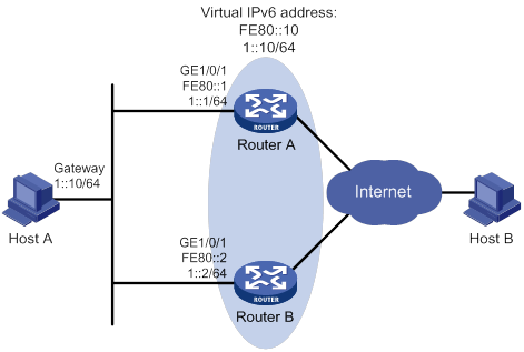
Configuration procedure
1. Configure Router A:
# Specify an IPv6 address for Router A.
<RouterA> system-view
[RouterA] interface gigabitethernet 1/0/1
[RouterA-GigabitEthernet1/0/1] ipv6 address fe80::1 link-local
[RouterA-GigabitEthernet1/0/1] ipv6 address 1::1 64
# Create VRRP group 1, and set its virtual IPv6 addresses to FE80::10 and 1::10.
[RouterA-GigabitEthernet1/0/1] vrrp ipv6 vrid 1 virtual-ip fe80::10 link-local
[RouterA-GigabitEthernet1/0/1] vrrp ipv6 vrid 1 virtual-ip 1::10
# Assign Router A a higher priority than Router B in VRRP group 1, so Router A can become the master.
[RouterA-GigabitEthernet1/0/1] vrrp ipv6 vrid 1 priority 110
# Configure Router A to operate in preemptive mode, so it can become the master whenever it operates correctly. Set the preemption delay to 5000 centiseconds to avoid frequent status switchover.
[RouterA-GigabitEthernet1/0/1] vrrp ipv6 vrid 1 preempt-mode delay 5000
# Enable Router A to send RA messages, so Host A can learn the default gateway address.
[RouterA-GigabitEthernet1/0/1] undo ipv6 nd ra halt
2. Configure Router B:
# Specify an IPv6 address for Router B.
<RouterB> system-view
[RouterB] interface gigabitethernet 1/0/1
[RouterB-GigabitEthernet1/0/1] ipv6 address fe80::2 link-local
[RouterB-GigabitEthernet1/0/1] ipv6 address 1::2 64
# Create VRRP group 1, and set its virtual IPv6 addresses to FE80::10 and 1::10.
[RouterB-GigabitEthernet1/0/1] vrrp ipv6 vrid 1 virtual-ip fe80::10 link-local
[RouterB-GigabitEthernet1/0/1] vrrp ipv6 vrid 1 virtual-ip 1::10
# Configure Router B to operate in preemptive mode, and set the preemption delay to 5000 centiseconds.
[RouterB-GigabitEthernet1/0/1] vrrp ipv6 vrid 1 preempt-mode delay 5000
# Enable Router B to send RA messages, so Host A can learn the default gateway address.
[RouterB-GigabitEthernet1/0/1] undo ipv6 nd ra halt
Verifying the configuration
# Ping Host B from Host A. (Details not shown.)
# Display detailed information about VRRP group 1 on Router A.
[RouterA-GigabitEthernet1/0/1] display vrrp ipv6 verbose
IPv6 Virtual Router Information:
Running Mode : Standard
Total number of virtual routers : 1
Interface GigabitEthernet1/0/1
VRID : 1 Adver Timer : 100
Admin Status : Up State : Master
Config Pri : 110 Running Pri : 110
Preempt Mode : Yes Delay Time : 5000
Auth Type : None
Virtual IP : FE80::10
1::10
Virtual MAC : 0000-5e00-0201
Master IP : FE80::1
# Display detailed information about VRRP group 1 on Router B.
[RouterB-GigabitEthernet1/0/1] display vrrp ipv6 verbose
IPv6 Virtual Router Information:
Running Mode : Standard
Total number of virtual routers : 1
Interface GigabitEthernet1/0/1
VRID : 1 Adver Timer : 100
Admin Status : Up State : Backup
Config Pri : 100 Running Pri : 100
Preempt Mode : Yes Delay Time : 5000
Become Master : 411ms left
Auth Type : None
Virtual IP : FE80::10
1::10
Master IP : FE80::1
The output shows that Router A is operating as the master in VRRP group 1 to forward packets from Host A to Host B.
# Disconnect the link between Host A and Router A, and verify that Host A can still ping Host B. (Details not shown.)
# Display detailed information about VRRP group 1 on Router B.
[RouterB-GigabitEthernet1/0/1] display vrrp ipv6 verbose
IPv6 Virtual Router Information:
Running Mode : Standard
Total number of virtual routers : 1
Interface GigabitEthernet1/0/1
VRID : 1 Adver Timer : 100
Admin Status : Up State : Master
Config Pri : 100 Running Pri : 100
Preempt Mode : Yes Delay Time : 5000
Auth Type : None
Virtual IP : FE80::10
1::10
Virtual MAC : 0000-5e00-0201
Master IP : FE80::2
The output shows that when Router A fails, Router B takes over to forward packets from Host A to Host B.
# Recover the link between Host A and Router A, and display detailed information about VRRP group 1 on Router A.
[RouterA-GigabitEthernet1/0/1] display vrrp ipv6 verbose
IPv6 Virtual Router Information:
Running Mode : Standard
Total number of virtual routers : 1
Interface GigabitEthernet1/0/1
VRID : 1 Adver Timer : 100
Admin Status : Up State : Master
Config Pri : 110 Running Pri : 110
Preempt Mode : Yes Delay Time : 5000
Auth Type : None
Virtual IP : FE80::10
1::10
Virtual MAC : 0000-5e00-0201
Master IP : FE80::1
The output shows that after Router A resumes normal operation, it becomes the master to forward packets from Host A to Host B.
Multiple VRRP groups configuration example
To implement load sharing between the VRRP groups, manually configure the default gateway 1::10 for some hosts and 1::20 for the other hosts on the subnet 1::/64.
Network requirements
As shown in Figure 29, Router A and Router B form two VRRP groups to implement load sharing and mutual backup. VRRP group 1 uses the virtual IP address 1::10/64 to provide gateway service for some hosts on the subnet 1::/64. VRRP group 2 uses the virtual IP address 1::20/64 to provide gateway service for the other hosts on the subnet.
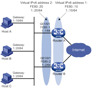
Configuration procedure
1. Configure Router A:
# Specify an IPv6 address for Router A.
<RouterA> system-view
[RouterA] interface gigabitethernet 1/0/1
[RouterA-GigabitEthernet1/0/1] ipv6 address fe80::1 link-local
[RouterA-GigabitEthernet1/0/1] ipv6 address 1::1 64
# Create VRRP group 1, and set its virtual IPv6 addresses to FE80::10 to 1::10.
[RouterA-GigabitEthernet1/0/1] vrrp ipv6 vrid 1 virtual-ip fe80::10 link-local
[RouterA-GigabitEthernet1/0/1] vrrp ipv6 vrid 1 virtual-ip 1::10
# Assign a higher priority to Router A than Router B in VRRP group 1, so Router A can become the master in the group.
[RouterA-GigabitEthernet1/0/1] vrrp ipv6 vrid 1 priority 110
# Create VRRP group 2, and set its virtual IPv6 addresses to FE80::20 and 1::20.
[RouterA-GigabitEthernet1/0/1] vrrp ipv6 vrid 2 virtual-ip fe80::20 link-local
[RouterA-GigabitEthernet1/0/1] vrrp ipv6 vrid 2 virtual-ip 1::20
2. Configure Router B:
# Specify an IPv6 address for Router B.
<RouterB> system-view
[RouterB] interface gigabitethernet 1/0/1
[RouterB-GigabitEthernet1/0/1] ipv6 address fe80::2 link-local
[RouterB-GigabitEthernet1/0/1] ipv6 address 1::2 64
# Create VRRP group 1, and set its virtual IPv6 addresses to FE80::10 and 1::10.
[RouterB-GigabitEthernet1/0/1] vrrp ipv6 vrid 1 virtual-ip fe80::10 link-local
[RouterB-GigabitEthernet1/0/1] vrrp ipv6 vrid 1 virtual-ip 1::10
# Create VRRP group 2, and set its virtual IPv6 addresses to FE80::20 and 1::20.
[RouterB-GigabitEthernet1/0/1] vrrp ipv6 vrid 2 virtual-ip fe80::20 link-local
[RouterB-GigabitEthernet1/0/1] vrrp ipv6 vrid 2 virtual-ip 1::20
# Assign Router B a higher priority than Router A in VRRP group 2, so Router B can become the master in the group.
[RouterB-GigabitEthernet1/0/1] vrrp ipv6 vrid 2 priority 110
Verifying the configuration
# Display detailed information about the VRRP groups on Router A.
[RouterA-GigabitEthernet1/0/1] display vrrp ipv6 verbose
IPv6 Virtual Router Information:
Running Mode : Standard
Total number of virtual routers : 2
Interface GigabitEthernet1/0/1
VRID : 1 Adver Timer : 100
Admin Status : Up State : Master
Config Pri : 110 Running Pri : 110
Preempt Mode : Yes Delay Time : 0
Auth Type : None
Virtual IP : FE80::10
1::10
Virtual MAC : 0000-5e00-0201
Master IP : FE80::1
Interface GigabitEthernet1/0/1
VRID : 2 Adver Timer : 100
Admin Status : Up State : Backup
Config Pri : 100 Running Pri : 100
Preempt Mode : Yes Delay Time : 0
Become Master : 410ms left
Auth Type : None
Virtual IP : FE80::20
1::20
Master IP : FE80::2
# Display detailed information about the VRRP groups on Router B.
[RouterB-GigabitEthernet1/0/1] display vrrp ipv6 verbose
IPv6 Virtual Router Information:
Running Mode : Standard
Total number of virtual routers : 2
Interface GigabitEthernet1/0/1
VRID : 1 Adver Timer : 100
Admin Status : Up State : Backup
Config Pri : 100 Running Pri : 100
Preempt Mode : Yes Delay Time : 0
Become Master : 407ms left
Auth Type : None
Virtual IP : FE80::10
1::10
Master IP : FE80::1
Interface GigabitEthernet1/0/1
VRID : 2 Adver Timer : 100
Admin Status : Up State : Master
Config Pri : 110 Running Pri : 110
Preempt Mode : Yes Delay Time : 0
Auth Type : None
Virtual IP : FE80::20
1::20
Virtual MAC : 0000-5e00-0202
Master IP : FE80::2
The output shows the following information:
· Router A is operating as the master in VRRP group 1 to forward Internet traffic for hosts that use the default gateway 1::10/64.
· Router B is operating as the master in VRRP group 2 to forward Internet traffic for hosts that use the default gateway 1::20/64.
VRRP load balancing configuration example
Network requirements
As shown in Figure 30, Router A, Router B, and Router C form a load balanced VRRP group and use the virtual IPv6 addresses FE80::10 and 1::10 to provide gateway service for the subnet 1::/64.
Hosts on subnet 1::/64 learn 1::10 as their default gateway from RA messages sent by the routers.
Configure VFs on Router A, Router B, or Router C to monitor their respective GigabitEthernet 1/0/2. When the interface on any of them fails, the weights of the VFs on the problematic router decrease so another AVF can take over.
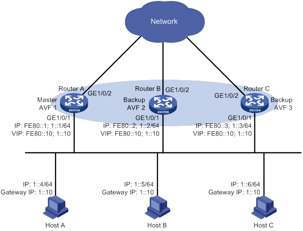
Configuration procedure
1. Configure Router A:
# Configure VRRP to operate in load balancing mode.
<RouterA> system-view
[RouterA] vrrp ipv6 mode load-balance
# Create VRRP group 1, and set its virtual IPv6 addresses to FE80::10 and 1::10.
[RouterA] interface gigabitethernet 1/0/1
[RouterA-GigabitEthernet1/0/1] ipv6 address fe80::1 link-local
[RouterA-GigabitEthernet1/0/1] ipv6 address 1::1 64
[RouterA-GigabitEthernet1/0/1] vrrp ipv6 vrid 1 virtual-ip fe80::10 link-local
[RouterA-GigabitEthernet1/0/1] vrrp ipv6 vrid 1 virtual-ip 1::10
# Assign Router A the highest priority in VRRP group 1, so Router A can become the master.
[RouterA-GigabitEthernet1/0/1] vrrp ipv6 vrid 1 priority 120
# Configure Router A to operate in preemptive mode, so it can become the master whenever it operates correctly. Set the preemption delay to 5000 centiseconds to avoid frequent status switchover.
[RouterA-GigabitEthernet1/0/1] vrrp ipv6 vrid 1 preempt-mode delay 5000
# Enable Router A to send RA messages, so hosts on subnet 1::/64 can learn the default gateway address.
[RouterA-GigabitEthernet1/0/1] undo ipv6 nd ra halt
[RouterA-GigabitEthernet1/0/1] quit
# Create track entry 1 to monitor the upstream link status of GigabitEthernet 1/0/2. When the upstream link fails, the track entry transits to Negative.
[RouterA] track 1 interface gigabitethernet 1/0/2
# Configure the VFs in VRRP group 1 to monitor track entry 1, and decrease their weights by 250 when the track entry transits to Negative.
[RouterA] interface gigabitethernet 1/0/1
[RouterA-GigabitEthernet1/0/1] vrrp ipv6 vrid 1 track 1 weight reduced 250
2. Configure Router B:
# Configure VRRP to operate in load balancing mode.
<RouterB> system-view
[RouterB] vrrp ipv6 mode load-balance
# Create VRRP group 1, and set its virtual IPv6 addresses to FE80::10 and 1::10.
[RouterB] interface gigabitethernet 1/0/1
[RouterB-GigabitEthernet1/0/1] ipv6 address fe80::2 link-local
[RouterB-GigabitEthernet1/0/1] ipv6 address 1::2 64
[RouterB-GigabitEthernet1/0/1] vrrp ipv6 vrid 1 virtual-ip fe80::10 link-local
[RouterB-GigabitEthernet1/0/1] vrrp ipv6 vrid 1 virtual-ip 1::10
# Assign Router B a higher priority than Router C in VRRP group 1, so Router B can become the master when Router A fails.
[RouterB-GigabitEthernet1/0/1] vrrp ipv6 vrid 1 priority 110
# Configure Router B to operate in preemptive mode and set the preemption delay to 5000 centiseconds.
[RouterB-GigabitEthernet1/0/1] vrrp ipv6 vrid 1 preempt-mode delay 5000
# Enable Router B to send RA messages, so hosts on subnet 1::/64 can learn the default gateway address.
[RouterB-GigabitEthernet1/0/1] undo ipv6 nd ra halt
[RouterB-GigabitEthernet1/0/1] quit
# Create track entry 1 to monitor the upstream link status of GigabitEthernet 1/0/2. When the upstream link fails, the track entry transits to Negative.
[RouterB] track 1 interface gigabitethernet 1/0/2
# Configure the VFs in VRRP group 1 to monitor track entry 1, and decrease their weights by 250 when the track entry transits to Negative.
[RouterB] interface gigabitethernet 1/0/1
[RouterB-GigabitEthernet1/0/1] vrrp ipv6 vrid 1 track 1 weight reduced 250
3. Configure Router C:
# Configure VRRP to operate in load balancing mode.
<RouterC> system-view
[RouterC] vrrp ipv6 mode load-balance
# Create VRRP group 1 and set its virtual IPv6 addresses to FE80::10 and 1::10.
[RouterC] interface gigabitethernet 1/0/1
[RouterC-GigabitEthernet1/0/1] ipv6 address fe80::3 link-local
[RouterC-GigabitEthernet1/0/1] ipv6 address 1::3 64
[RouterC-GigabitEthernet1/0/1] vrrp ipv6 vrid 1 virtual-ip fe80::10 link-local
[RouterC-GigabitEthernet1/0/1] vrrp ipv6 vrid 1 virtual-ip 1::10
# Configure Router C to operate in preemptive mode and set the preemption delay to 5000 centiseconds.
[RouterC-GigabitEthernet1/0/1] vrrp ipv6 vrid 1 preempt-mode delay 5000
# Enable Router C to send RA messages, so hosts on subnet 1::/64 can learn the default gateway address.
[RouterC-GigabitEthernet1/0/1] undo ipv6 nd ra halt
[RouterC-GigabitEthernet1/0/1] quit
# Create track entry 1 to monitor the upstream link status of GigabitEthernet 1/0/2. When the upstream link fails, the track entry transits to Negative.
[RouterC] track 1 interface gigabitethernet 1/0/2
# Configure the VFs in VRRP group 1 to monitor track entry 1, and decrease their weights by 250 when the track entry transits to Negative.
[RouterC] interface gigabitethernet 1/0/1
[RouterC-GigabitEthernet1/0/1] vrrp ipv6 vrid 1 track 1 weight reduced 250
Verifying the configuration
# Verify that Host A can ping the external network. (Details not shown.)
# Display detailed information about VRRP group 1 on Router A.
[RouterA-GigabitEthernet1/0/1] display vrrp ipv6 verbose
IPv6 Virtual Router Information:
Running Mode : Load Balance
Total number of virtual routers : 1
Interface GigabitEthernet1/0/1
VRID : 1 Adver Timer : 100
Admin Status : Up State : Master
Config Pri : 120 Running Pri : 120
Preempt Mode : Yes Delay Time : 5000
Auth Type : None
Virtual IP : FE80::10
1::10
Member IP List : FE80::1 (Local, Master)
FE80::2 (Backup)
FE80::3 (Backup)
Forwarder Information: 3 Forwarders 1 Active
Config Weight : 255
Running Weight : 255
Forwarder 01
State : Active
Virtual MAC : 000f-e2ff-4011 (Owner)
Owner ID : 0000-5e01-1101
Priority : 255
Active : local
Forwarder 02
State : Listening
Virtual MAC : 000f-e2ff-4012 (Learnt)
Owner ID : 0000-5e01-1103
Priority : 127
Active : FE80::2
Forwarder 03
State : Listening
Virtual MAC : 000f-e2ff-4013 (Learnt)
Owner ID : 0000-5e01-1105
Priority : 127
Active : FE80::3
Forwarder Weight Track Information:
Track Object : 1 State : Positive Weight Reduced : 250
# Display detailed information about VRRP group 1 on Router B.
[RouterB-GigabitEthernet1/0/1] display vrrp ipv6 verbose
IPv6 Virtual Router Information:
Running Mode : Load Balance
Total number of virtual routers : 1
Interface GigabitEthernet1/0/1
VRID : 1 Adver Timer : 100
Admin Status : Up State : Backup
Config Pri : 110 Running Pri : 110
Preempt Mode : Yes Delay Time : 5000
Become Master : 400ms left
Auth Type : None
Virtual IP : FE80::10
1::10
Member IP List : FE80::2 (Local, Backup)
FE80::1 (Master)
FE80::3 (Backup)
Forwarder Information: 3 Forwarders 1 Active
Config Weight : 255
Running Weight : 255
Forwarder 01
State : Listening
Virtual MAC : 000f-e2ff-4011 (Learnt)
Owner ID : 0000-5e01-1101
Priority : 127
Active : FE80::1
Forwarder 02
State : Active
Virtual MAC : 000f-e2ff-4012 (Owner)
Owner ID : 0000-5e01-1103
Priority : 255
Active : local
Forwarder 03
State : Listening
Virtual MAC : 000f-e2ff-4013 (Learnt)
Owner ID : 0000-5e01-1105
Priority : 127
Active : FE80::3
Forwarder Weight Track Information:
Track Object : 1 State : Positive Weight Reduced : 250
# Display detailed information about VRRP group 1 on Router C.
[RouterC-GigabitEthernet1/0/1] display vrrp ipv6 verbose
IPv6 Virtual Router Information:
Running Mode : Load Balance
Total number of virtual routers : 1
Interface GigabitEthernet1/0/1
VRID : 1 Adver Timer : 100
Admin Status : Up State : Backup
Config Pri : 100 Running Pri : 100
Preempt Mode : Yes Delay Time : 5000
Become Master : 402ms left
Auth Type : None
Virtual IP : FE80::10
1::10
Member IP List : FE80::3 (Local, Backup)
FE80::1 (Master)
FE80::2 (Backup)
Forwarder Information: 3 Forwarders 1 Active
Config Weight : 255
Running Weight : 255
Forwarder 01
State : Listening
Virtual MAC : 000f-e2ff-4011 (Learnt)
Owner ID : 0000-5e01-1101
Priority : 127
Active : FE80::1
Forwarder 02
State : Listening
Virtual MAC : 000f-e2ff-4012 (Learnt)
Owner ID : 0000-5e01-1103
Priority : 127
Active : FE80::2
Forwarder 03
State : Active
Virtual MAC : 000f-e2ff-4013 (Owner)
Owner ID : 0000-5e01-1105
Priority : 255
Active : local
Forwarder Weight Track Information:
Track Object : 1 State : Positive Weight Reduced : 250
The output shows that Router A is the master in VRRP group 1, and each of the three routers has one AVF and two LVFs.
# Disconnect the link of GigabitEthernet 1/0/2 on Router A, and display detailed information about VRRP group 1 on Router A.
[RouterA-GigabitEthernet1/0/1] display vrrp ipv6 verbose
IPv6 Virtual Router Information:
Running Mode : Load Balance
Total number of virtual routers : 1
Interface GigabitEthernet1/0/1
VRID : 1 Adver Timer : 100
Admin Status : Up State : Master
Config Pri : 120 Running Pri : 120
Preempt Mode : Yes Delay Time : 5000
Auth Type : None
Virtual IP : FE80::10
1::10
Member IP List : FE80::1 (Local, Master)
FE80::2 (Backup)
FE80::3 (Backup)
Forwarder Information: 3 Forwarders 0 Active
Config Weight : 255
Running Weight : 5
Forwarder 01
State : Initialize
Virtual MAC : 000f-e2ff-4011 (Owner)
Owner ID : 0000-5e01-1101
Priority : 0
Active : FE80::3
Forwarder 02
State : Initialize
Virtual MAC : 000f-e2ff-4012 (Learnt)
Owner ID : 0000-5e01-1103
Priority : 0
Active : FE80::2
Forwarder 03
State : Initialize
Virtual MAC : 000f-e2ff-4013 (Learnt)
Owner ID : 0000-5e01-1105
Priority : 0
Active : FE80::3
Forwarder Weight Track Information:
Track Object : 1 State : Negative Weight Reduced : 250
# Display detailed information about VRRP group 1 on Router C.
[RouterC-GigabitEthernet1/0/1] display vrrp ipv6 verbose
IPv6 Virtual Router Information:
Running Mode : Load Balance
Total number of virtual routers : 1
Interface GigabitEthernet1/0/1
VRID : 1 Adver Timer : 100
Admin Status : Up State : Backup
Config Pri : 100 Running Pri : 100
Preempt Mode : Yes Delay Time : 5000
Become Master : 401ms left
Auth Type : None
Virtual IP : FE80::10
1::10
Member IP List : FE80::3 (Local, Backup)
FE80::1 (Master)
FE80::2 (Backup)
Forwarder Information: 3 Forwarders 2 Active
Config Weight : 255
Running Weight : 255
Forwarder 01
State : Active
Virtual MAC : 000f-e2ff-4011 (Take Over)
Owner ID : 0000-5e01-1101
Priority : 85
Active : local
Forwarder 02
State : Listening
Virtual MAC : 000f-e2ff-4012 (Learnt)
Owner ID : 0000-5e01-1103
Priority : 85
Active : FE80::2
Forwarder 03
State : Active
Virtual MAC : 000f-e2ff-4013 (Owner)
Owner ID : 0000-5e01-1105
Priority : 255
Active : local
Forwarder Weight Track Information:
Track Object : 1 State : Positive Weight Reduced : 250
The output shows that when GigabitEthernet 1/0/2 on Router A fails, the weights of the VFs on Router A drop below the lower limit of failure. All VFs on Router A transit to the Initialized state and cannot forward traffic. The VF for MAC address 000f-e2ff-4011 on Router C becomes the AVF to forward traffic.
# When the timeout timer (about 1800 seconds) expires, display detailed information about VRRP group 1 on Router C.
[RouterC-GigabitEthernet1/0/1] display vrrp ipv6 verbose
IPv6 Virtual Router Information:
Running Mode : Load Balance
Total number of virtual routers : 1
Interface GigabitEthernet1/0/1
VRID : 1 Adver Timer : 100
Admin Status : Up State : Backup
Config Pri : 100 Running Pri : 100
Preempt Mode : Yes Delay Time : 5000
Become Master : 400ms left
Auth Type : None
Virtual IP : FE80::10
1::10
Member IP List : FE80::3 (Local, Backup)
FE80::1 (Master)
FE80::2 (Backup)
Forwarder Information: 2 Forwarders 1 Active
Config Weight : 255
Running Weight : 255
Forwarder 02
State : Listening
Virtual MAC : 000f-e2ff-4012 (Learnt)
Owner ID : 0000-5e01-1103
Priority : 127
Active : FE80::2
Forwarder 03
State : Active
Virtual MAC : 000f-e2ff-4013 (Owner)
Owner ID : 0000-5e01-1105
Priority : 255
Active : local
Forwarder Weight Track Information:
Track Object : 1 State : Positive Weight Reduced : 250
The output shows that when the timeout timer expires, the VF for virtual MAC address 000f-e2ff-4011 is removed. The VF no longer forwards the packets destined for the MAC address.
# When Router A fails, display detailed information about VRRP group 1 on Router B.
[RouterB-GigabitEthernet1/0/1] display vrrp ipv6 verbose
IPv6 Virtual Router Information:
Running Mode : Load Balance
Total number of virtual routers : 1
Interface GigabitEthernet1/0/1
VRID : 1 Adver Timer : 100
Admin Status : Up State : Master
Config Pri : 110 Running Pri : 110
Preempt Mode : Yes Delay Time : 5000
Auth Type : None
Virtual IP : FE80::10
1::10
Member IP List : FE80::2 (Local, Master)
FE80::3 (Backup)
Forwarder Information: 2 Forwarders 1 Active
Config Weight : 255
Running Weight : 255
Forwarder 02
State : Active
Virtual MAC : 000f-e2ff-4012 (Owner)
Owner ID : 0000-5e01-1103
Priority : 255
Active : local
Forwarder 03
State : Listening
Virtual MAC : 000f-e2ff-4013 (Learnt)
Owner ID : 0000-5e01-1105
Priority : 127
Active : FE80::3
Forwarder Weight Track Information:
Track Object : 1 State : Positive Weight Reduced : 250
The output shows the following information:
· When Router A fails, Router B becomes the master because it has a higher priority than Router C.
· The VF for virtual MAC address 000f-e2ff-4011 is removed.
Troubleshooting VRRP
An error prompt is displayed
Symptom
An error prompt "The virtual router detected a VRRP configuration error." is displayed during configuration.
Analysis
This symptom is probably caused by the following reasons:
· The VRRP advertisement interval in the packet is not the same as that for the current VRRP group (in VRRPv2 only).
· The number of virtual IP addresses in the packet is not the same as that for the current VRRP group.
· The virtual IP address list is not the same as that for the current VRRP group.
· A device in the VRRP group receives illegitimate VRRP packets. For example, the IP address owner receives a VRRP packet with the priority 255.
Solution
To resolve the problem:
1. Modify the configuration on routers in VRRP groups to ensure consistent configuration.
2. Take fault location and anti-attack measures to eliminate potential threats.
3. If the problem persists, contact H3C Support.
Multiple masters appear in a VRRP group
Symptom
Multiple masters appear in a VRRP group.
Analysis
It is normal for a VRRP group to have multiple masters for a short time, and this situation requires no manual intervention.
If multiple masters coexist for a longer period, check for the following conditions:
· The masters cannot receive advertisements from each other.
· The received advertisements are illegitimate.
Solution
To resolve the problem:
1. Ping between these masters:
? If the ping operation fails, examine network connectivity.
? If the ping operation succeeds, check for configuration inconsistencies in the number of virtual IP addresses, virtual IP addresses, and authentication. For IPv4 VRRP, also make sure the same version of VRRP is configured on all routers in the VRRP group. For VRRPv2, make sure the same VRRP advertisement interval is configured on the routers in the VRRP group.
2. If the problem persists, contact H3C Support.
Fast VRRP state flapping
Symptom
Fast VRRP state flapping occurs.
Analysis
The VRRP advertisement interval is set too short.
Solution
To resolve the problem:
1. Increase the interval for sending VRRP advertisements or introduce a preemption delay.
2. If the problem persists, contact H3C Support.
Configuring process placement
Overview
Process placement enables placing processes to specific CPUs (also called nodes) on the main processing units (MPUs) in your system for optimal distribution of CPU and memory resources.
Process
A process contains a set of codes and provides specific functionality. For example, an AAA process provides AAA functions.
Each process runs in a protected memory space to prevent problems with one process from impacting the entire system.
1:N process redundancy
The system backs up each active process running on one node to all the other nodes. When an active process fails, one of its standby processes promptly takes over without impacting any other service.
1:N process redundancy provides the following benefits:
· Improves service availability.
· Enables the system to quickly regain reliability after device status changes in such conditions as insertion and removal of cards, IRF split, and removal of an IRF member.
Process placement policy and optimization
Process placement policies
An active process running only on the active MPU does not support placement optimization. If you configure a process placement policy for the process, the system displays a configuration failure message. When such an active process fails, the system automatically restarts the process. The standby processes are used for active/standby switchover and ISSU.
Some active processes can run on either the active or standby MPU. When such an active process fails, the system uses a placement policy to select a new active process among standby processes.
The system provides a default process placement policy that takes effect for all processes. You can modify the default placement policy in the view you enter by using the placement program default command. You can also configure a placement policy for a specific process in the view you enter by using the placement program program-name [ instance instance-name ] command. A placement policy for a process takes precedence over the default process placement policy.
By default, the default process placement policy defines the following rules:
· The active process runs on the main CPU of the active MPU, and the standby processes run on the main CPU of the standby MPU. (Distributed devices in standalone mode.)
· The active process runs on the main CPU of the master, and the standby processes run on the main CPU of the subordinate device. (Centralized devices in IRF mode.)
· The active process runs on the main CPU of the global active MPU, and the standby processes run on the main CPU of the global standby MPU. (Distributed devices in IRF mode.)
· A process runs at the location where it ran the last time and does not move to any other location during startup or operation.
· The addition of a new node does not impact current active processes. A new active process selects one node with sufficient CPU and memory resources. (You can use the display cpu-usage and display memory commands to view CPU and memory usage information.)
Optimizing process placement
You can configure the following settings for a process placement policy to optimize process placement:
· affinity location-set—Location affinity, the preference for the process to run on a specific node.
· affinity location-type—Location type affinity, the preference for the process to run on a particular type of node. For more information about node types, see "Configuring a location type affinity."
· affinity program—Process affinity, the preference for the process to run on the same node as a particular process.
· affinity self—Self affinity, the preference for one instance of the process to run on the same node as any other instance of the process.
Affinities include positive affinities (attract) and negative affinities (repulse), all represented by integers in the range of 1 to 100000.
· The higher the attract value, the stronger the preference.
· The higher the repulse value, the weaker the preference.
After you apply new placement policies, the system makes placement decisions based on the new policies, node resources, and topology status. If the new location for an active process is different from the current node, the system changes the state of the process to standby, and uses the standby process on the preferred location as the new active process.
Compatibility information
Feature and hardware compatibility
|
Hardware |
Process placement compatibility |
|
MSR810/810-W/810-W-DB/810-LM/810-W-LM/810-10-PoE/810-LM-HK/810-W-LM-HK/810-LMS/810-LUS |
No |
|
MSR2600-6-X1/2600-10-X1 |
No |
|
MSR 2630 |
Yes |
|
MSR3600-28/3600-51 |
Yes |
|
MSR3600-28-SI/3600-51-SI |
No |
|
MSR3610-X1/3610-X1-DP/3610-X1-DC/3610-X1-DP-DC |
Yes |
|
MSR 3610/3620/3620-DP/3640/3660 |
Yes |
|
MSR5620/5660/5680 |
Yes |
|
Hardware |
Process placement compatibility |
|
MSR810-LM-GL |
No |
|
MSR810-W-LM-GL |
No |
|
MSR830-6EI-GL |
No |
|
MSR830-10EI-GL |
No |
|
MSR830-6HI-GL |
No |
|
MSR830-10HI-GL |
No |
|
MSR2600-6-X1-GL |
No |
|
MSR3600-28-SI-GL |
No |
Command and hardware compatibility
Commands and descriptions for centralized devices apply to the following routers:
· MSR810/810-W/810-W-DB/810-LM/810-W-LM/810-10-PoE/810-LM-HK/810-W-LM-HK/810-LMS/810-LUS.
· MSR2600-6-X1/2600-10-X1.
· MSR 2630.
· MSR3600-28/3600-51.
· MSR3600-28-SI/3600-51-SI.
· MSR3610-X1/3610-X1-DP/3610-X1-DC/3610-X1-DP-DC.
· MSR 3610/3620/3620-DP/3640/3660.
· MSR810-LM-GL/810-W-LM-GL/830-6EI-GL/830-10EI-GL/830-6HI-GL/830-10HI-GL/2600-6-X1-GL/3600-28-SI-GL.
Commands and descriptions for distributed devices apply to the following routers:
· MSR5620.
· MSR 5660.
· MSR 5680.
Configuration restrictions and guidelines
When you configure process placement, follow these restrictions and guidelines:
· Configuring process placement on a device with only one MPU does not change the location of processes. All processes run on the main CPU of the MPU.
· Configuring process placement on a device with multiple MPUs places specific active processes to specific CPUs. In case of multiple CPUs, the system performs 1:N process redundancy, where N must be less than the number of CPUs. The number of standby processes and their CPU locations vary by function module. The system by default automatically determines the location for each active process, and there is no need to optimize process placement. If optimization is needed, contact H3C Support to avoid service interruption.
· Process placement applies only to MPUs.
· The main and auxiliary CPUs on an MPU, if any, are equal for process placement. You can place an active process either on a main CPU or an auxiliary CPU. You can view the final result by using the placement reoptimize command.
Process placement configuration task list
|
Tasks at a glance |
|
|
Configuring process placement policy: · (Optional.) Configuring a location affinity · (Optional.) Configuring a location type affinity · (Optional.) Configuring a process affinity · (Optional.) Configuring a self affinity |
|
|
(Required.) Optimizing process placement |
Configuring process placement policy
Configuring a location affinity
|
Step |
Command |
Remarks |
|
1. Enter system view. |
system-view |
N/A |
|
2. Enter placement process view. |
·
Enter default placement process view: ·
Enter placement process view: |
Settings in default placement process view take effect for all processes. Settings in placement process view take effect only for the specified process. |
|
3. Set the location affinity. |
affinity location-set { slot slot-number }&<1-5> { attract strength | default | none | repulse strength } |
By default, no location affinity is set. |
|
4. Set the location affinity (distributed devices in IRF mode). |
affinity location-set { chassis chassis-number slot slot-number }&<1-5> { attract strength | default | none | repulse strength } |
By default, no location affinity is set. |
Configuring a location type affinity
The following location types are available:
· current—Current location of the active process, which can be displayed with the display placement program command.
· paired—Locations of standby processes.
· primary—Active MPU. (Distributed devices in standalone mode.)
· primary—Master device. (Centralized devices in IRF mode.)
· primary—Global active MPU. (Distributed devices in IRF mode.)
To configure a location type affinity:
|
Step |
Command |
Remarks |
|
1. Enter system view. |
system-view |
N/A |
|
2. Enter placement process view. |
·
Enter default placement process view: ·
Enter placement process view: |
Settings in default placement process view take effect for all processes. Settings in placement process view take effect only for the specified process. |
|
3. Set the location type affinity. |
affinity location-type { current | paired | primary } { attract strength | repulse strength | default | none } |
By default, no location type affinity is set. |
Configuring a process affinity
|
Step |
Command |
Remarks |
|
1. Enter system view. |
system-view |
N/A |
|
2. Enter placement process view. |
·
Enter default placement process view: ·
Enter placement process view: |
Settings in default placement process view take effect for all processes. Settings in placement process view take effect only for the specified process. |
|
3. Configure the affinity for the process to run on the same location as another process. |
affinity program program-name { attract strength | default | none | repulse strength } |
By default, no process affinity is set. |
Configuring a self affinity
Perform this task to configure the preference for one instance of a process to run on the same node as any other instance of the process. The self affinity setting does not take effect for a process that has only one instance.
To configure a self affinity:
|
Step |
Command |
Remarks |
|
1. Enter system view. |
system-view |
N/A |
|
2. Enter placement process view. |
·
Enter default placement process view: ·
Enter placement process view: |
Settings in default placement process view take effect for all processes. Settings in placement process view take effect only for the specified process. |
|
3. Configure a self affinity. |
affinity self { attract strength | repulse strength | default | none } |
By default, no self affinity is set. |
Optimizing process placement
|
Step |
Command |
Remarks |
|
1. Enter system view. |
system-view |
N/A |
|
2. Optimize process placement. |
placement reoptimize |
To keep the system stable, do not perform any tasks that require process restart when you execute this command. |
Displaying process placement
Execute display commands in any view.
|
Task |
Command |
|
Display process placement policy information. |
display placement policy program { program-name | all | default } |
|
Display the location of a process. |
display placement program { program-name | all } |
|
Display the running processes on a specific location (distributed devices in standalone mode/centralized devices in IRF mode). |
display placement location { slot slot-number | all } |
|
Display the running processes on a specific location (distributed devices in IRF mode). |
display placement location { chassis chassis-number slot slot-number | all } |
|
Display the predicted location of a process after process placement optimization. |
display placement reoptimize program { program-name [ instance instance-name ] | all } |
|
Display service group information. |
display ha service-group { program-name [ instance instance-name ] | all } |
Configuring DLDP
Overview
A link becomes unidirectional when only one end of the link can receive packets from the other end.
Unidirectional fiber links occur in the following cases:
· Fibers are cross-connected.
· A fiber is not connected at one end or one fiber of a fiber pair is broken.
Figure 31 shows a correct fiber connection and two types of unidirectional fiber connections.
Figure 31 Correct and incorrect fiber connections
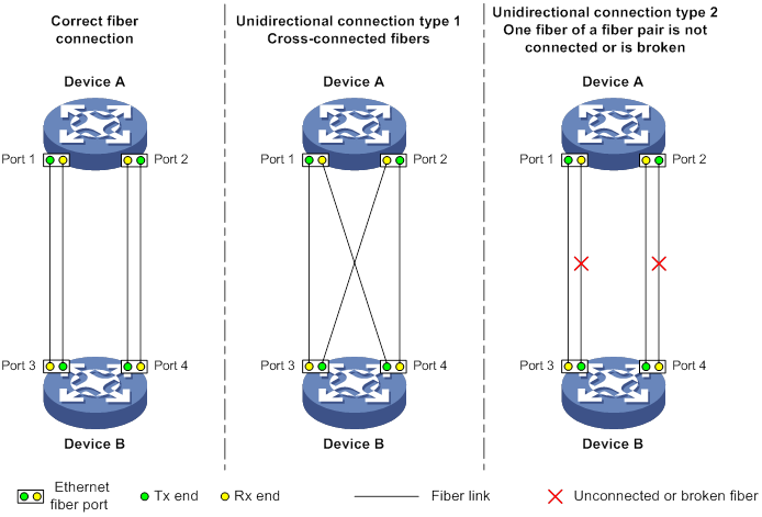
Physical layer detection mechanisms, such as auto-negotiation, can detect physical signals and faults. However, they cannot detect communication failures for unidirectional links where the physical layer is in connected state.
As a data link layer protocol, the Device Link Detection Protocol (DLDP) detects the following:
· Whether the fiber link or twisted-pair link is correctly connected at the link layer.
· Whether the two ends of the link can exchange packets correctly.
When DLDP detects unidirectional links, it can automatically shut down the faulty port to avoid network problems. Alternatively, a user can manually shut down the faulty port. DLDP cooperates with physical layer protocols to monitor link status and avoid physical and logical unidirectional links.
Basic concepts
DLDP neighbor states
If port A can receive link-layer packets from port B on the same link, port B is a DLDP neighbor of port A. Two ports that can exchange packets are neighbors.
Table 4 DLDP neighbor states
|
DLDP timer |
Description |
|
Confirmed |
The link to a DLDP neighbor is bidirectional. |
|
Unconfirmed |
The state of the link to a newly discovered neighbor is not determined. |
DLDP port states
A DLDP-enabled port is called a DLDP port. A DLDP port can have multiple neighbors, and its state varies by the DLDP neighbor state.
Table 5 DLDP port states
|
State |
Description |
|
Initial |
DLDP is enabled on the port, but is disabled globally. |
|
Inactive |
DLDP is enabled on the port and globally, and the link is physically down. |
|
Bidirectional |
DLDP is enabled on the port and globally, and at least one neighbor in Confirmed state exists. |
|
Unidirectional |
DLDP is enabled on the port and globally, and no neighbor in Confirmed state exists. In this state, a port does not send or receive packets other than DLDP packets any more. |
DLDP timers
Table 6 DLDP timers
|
DLDP timer |
Description |
|
Advertisement timer |
Advertisement packet sending interval (the default is 5 seconds and is configurable). |
|
Probe timer |
Probe packet sending interval. This timer is set to 1 second. |
|
Echo timer |
The Echo timer is triggered when a probe is launched for a new neighbor. This timer is set to 10 seconds. |
|
Entry timer |
When a new neighbor joins, a neighbor entry is created and the corresponding entry timer is triggered if the neighbor is in Confirmed state. When an Advertisement is received, the device updates the corresponding neighbor entry and the Entry timer. The setting of an Entry timer is three times that of the Advertisement timer. |
|
Enhanced timer |
The Enhanced timer is triggered, together with the Echo timer, when the Entry timer expires. The Enhanced timer is set to 1 second. |
|
DelayDown timer |
If a port is physically down, the device triggers the DelayDown timer, rather than removing the corresponding neighbor entry. The default DelayDown timer is 1 second and is configurable. When the DelayDown timer expires, the device removes the corresponding DLDP neighbor information if the port is down, and does not perform any operation if the port is up. |
|
RecoverProbe timer |
This timer is set to 2 seconds. A port in unidirectional state regularly sends RecoverProbe packets to detect whether a unidirectional link has been restored to bidirectional. |
DLDP authentication mode
You can use DLDP authentication to prevent network attacks and illegal detecting.
Table 7 DLDP authentication mode
|
Authentication mode |
Processing at the DLDP packet sending side |
Processing at the DLDP packet receiving side |
|
Non-authentication |
The sending side sets the Authentication field of DLDP packets to 0. |
The receiving side examines the authentication information of received DLDP packets and drops packets where the authentication information conflicts with the local configuration. |
|
Plaintext authentication |
The sending side sets the Authentication field to the password configured in plain text. |
|
|
MD5 authentication |
The sending side encrypts the user configured password by using MD5 algorithm, and assigns the digest to the Authentication field. |
How DLDP works
Detecting one neighbor
When two devices are connected through an optical fiber or a network cable, enable DLDP to detect unidirectional links to the neighbor. The following illustrates the unidirectional link detection process in two cases:
· Unidirectional links occur before you enable DLDP.
Figure 32 Cross-connected fibers
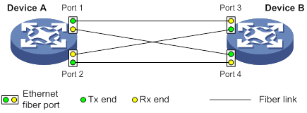
As shown in Figure 32, before you enable DLDP, the optical fibers between Device A and Device B are cross-connected. After you enable DLDP, the four ports are all up and in unidirectional state, and they send RecoverProbe packets. Take Port 1 as an example to illustrate the unidirectional link detection process.
a. Port 1 receives the RecoverProbe packet from Port 4, and returns a RecoverEcho packet.
b. Port 4 cannot receive any RecoverEcho packet from Port 1, so Port 4 cannot become the neighbor of Port 1.
c. Port 3 can receive the RecoverEcho packet from Port 1, but Port 3 is not the intended destination, so Port 3 cannot become the neighbor of Port 1.
The same process occurs on the other three ports. The four ports are all in unidirectional state.
· Unidirectional links occur after you enable DLDP.
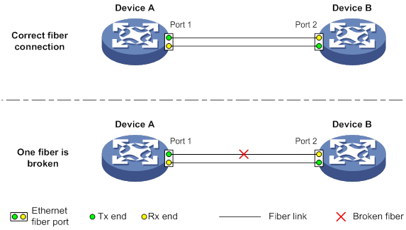
As shown in Figure 33, Device A and Device B are connected through an optical fiber. After you enable DLDP, Port 1 and Port 2 establish the bidirectional neighborship in the following way:
a. Port 1 that is physically up enters the unidirectional state and sends a RecoverProbe packet.
b. After receiving the RecoverProbe packet, Port 2 returns a RecoverEcho packet.
c. After Port 1 receives the RecoverEcho packet, it examines the neighbor information in the packet. If the neighbor information matches the local information, Port 1 establishes the neighborship with Port 2 and transits to bidirectional state. Port 1 then starts the Entry timer and periodically sends Advertisement packets.
d. After Port 2 receives the Advertisement packet, it establishes the Unconfirmed neighborship with Port 1. Port 2 then starts the Echo timer and Probe timer, and periodically sends Probe packets.
e. After receiving the Probe packet, Port 1 returns an Echo packet.
f. After Port 2 receives the Echo packet, it examines the neighbor information in the packet. If the neighbor information matches the local information, the neighbor state of Port 1 becomes Confirmed. Port 2 then transits to bidirectional state, starts the Entry timer, and periodically sends Advertisement packets.
The bidirectional neighborship between Port 1 and Port 2 is now established.
After that, when Port 2's Rx end fails to receive signals, Port 2 is physically down and enters the Inactive state. Because Port 2's Tx end can still send signals to Port 1, Port 1 stays up. After the Entry timer for Port 2 expires, Port 1 starts the Enhanced timer and Echo timer, and sends a probe packet to Port 2. Because Port 1's Tx line is broken, Port 1 cannot receive the Echo packet from Port 2 after the Echo timer expires. Port 1 then enters the unidirectional state, and sends a Disable packet to Port 2. At the same time, Port 1 deletes the neighborship with Port 2, and starts the RecoverProbe timer. Port 2 stays in Inactive state during this process.
When an interface is physically down, but the Tx end of the interface is still operating, DLDP sends a LinkDown packet to inform the peer to delete the relevant neighbor entry.
Detecting multiple neighbors
When multiple devices are connected through a hub, enable DLDP on all interfaces connected to the hub to detect unidirectional links among the neighbors. When no Confirmed neighbor exists, an interface enters the unidirectional state.
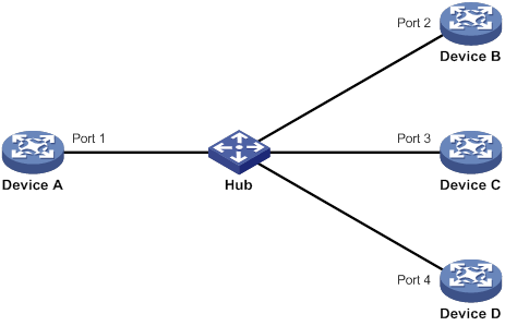
As shown in Figure 34, Device A through Device D are connected through a hub, and enabled with DLDP. When Ports 1, 2, and 3 detect that the link to Port 4 fails, they delete the neighborship with Port 4, but stay in bidirectional state.
Configuration restrictions and guidelines
When you configure DLDP, follow these configuration restrictions and guidelines:
· For DLDP to operate correctly, enable DLDP on both sides and make sure the following settings are consistent:
? Interval to send Advertisement packets.
? DLDP authentication mode.
? Password.
· For DLDP to operate correctly, configure the full duplex mode for the ports at the two ends of the link, and configure the same speed for the two ports.
DLDP configuration task list
|
Tasks at a glance |
|
(Required.) Enabling DLDP |
|
(Optional.) Setting the interval to send advertisement packets |
|
(Optional.) Setting the DelayDown timer |
|
(Optional.) Setting the port shutdown mode |
|
(Optional.) Configuring DLDP authentication |
Enabling DLDP
To correctly configure DLDP on the device, you must enable DLDP globally and on each port.
To enable DLDP:
|
Command |
Remarks |
|
|
1. Enter system view. |
system-view |
N/A |
|
2. Enable DLDP globally. |
dldp global enable |
By default, DLDP is globally disabled. |
|
3. Enter Ethernet interface view. |
interface interface-type interface-number |
N/A |
|
4. Enable DLDP. |
dldp enable |
By default, DLDP is disabled on an interface. |
Setting the interval to send advertisement packets
To make sure DLDP can detect unidirectional links before network performance deteriorates, set the advertisement interval appropriate for your network environment. As a best practice, use the default interval.
To set the Advertisement packet sending interval:
|
Step |
Command |
Remarks |
|
1. Enter system view. |
system-view |
N/A |
|
2. Set the interval to send Advertisement packets. |
dldp interval interval |
By default, the interval is 5 seconds. |
Setting the DelayDown timer
When the Tx line fails, some ports might go down and then come up again, causing optical signal jitters on the Rx line. To prevent the device from removing neighbor entries in such cases, set the DelayDown timer for the device. The device starts the DelayDown timer when a port goes down due to a Tx line failure. If the port remains down when the timer expires, the device removes the DLDP neighbor information. If the port comes up, the device takes no action.
To set the DelayDown timer:
|
Step |
Command |
Remarks |
|
1. Enter system view. |
system-view |
N/A |
|
2. Set the DelayDown timer. |
dldp delaydown-timer time |
The default is 1 second. The DelayDown timer setting applies to all DLDP-enabled ports. |
Setting the port shutdown mode
On detecting a unidirectional link, DLDP shuts down the ports in one of the following modes:
· Auto mode—When a unidirectional link is detected, DLDP changes the DLDP port state to unidirectional. The unidirectional port periodically sends RecoverProbe packets. When a correct RecoverEcho packet is received, the link is restored to a bidirectional link, and the port state changes from unidirectional to bidirectional. This process is called link auto-recovery mechanism.
· Manual mode—When a unidirectional link is detected, DLDP does not shut down the port, and you must manually shut it down. When the link state is restored to bidirectional, you must manually bring up the port. Use this mode to prevent normal links from being shut down because of false unidirectional link reports in the following cases:
? The network performance is low.
? The device is busy.
? The CPU usage is high.
To set port shutdown mode:
|
Step |
Command |
Remarks |
|
1. Enter system view. |
system-view |
N/A |
|
2. Set port shutdown mode. |
dldp unidirectional-shutdown { auto | manual } |
The default mode is auto. |
Configuring DLDP authentication
You can guard your network against attacks and malicious probes by configuring an appropriate DLDP authentication mode, which can be plain text authentication or MD5 authentication. If your network is safe, you can choose not to authenticate.
To configure DLDP authentication:
|
Step |
Command |
Remarks |
|
1. Enter system view. |
system-view |
N/A |
|
2. Configure a DLDP authentication mode. |
dldp authentication-mode { md5 | none | simple } |
The default authentication mode is none. |
|
3. Configure the password for DLDP authentication. |
dldp authentication-password { cipher | simple } string |
By default, no password is configured for DLDP authentication. If you do not configure the authentication password after you configure the authentication mode, the authentication mode is none no matter which authentication mode you configure. |
Displaying and maintaining DLDP
Execute display commands in any view and the reset command in user view.
|
Task |
Command |
|
Display the DLDP configuration globally and of a port. |
display dldp [ interface interface-type interface-number ] |
|
Display the statistics on DLDP packets passing through a port. |
display dldp statistics [ interface interface-type interface-number ] |
|
Clear the statistics on DLDP packets passing through a port. |
reset dldp statistics [ interface interface-type interface-number ] |
DLDP configuration examples
Automatically shutting down unidirectional links
Network requirements
As shown in Figure 35, Device A and Device B are connected through two fiber pairs.
Configure DLDP to automatically shut down the faulty port upon detecting a unidirectional link, and automatically bring up the port after you clear the fault.
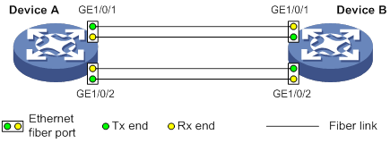
Configuration procedure
1. Configure Device A:
# Enable DLDP globally.
<DeviceA> system-view
[DeviceA] dldp global enable
# Configure GigabitEthernet 1/0/1 to operate in full duplex mode and at 1000 Mbps, and enable DLDP on the port.
[DeviceA] interface gigabitethernet 1/0/1
[DeviceA-GigabitEthernet1/0/1] duplex full
[DeviceA-GigabitEthernet1/0/1] speed 1000
[DeviceA-GigabitEthernet1/0/1] dldp enable
[DeviceA-GigabitEthernet1/0/1] quit
# Configure GigabitEthernet 1/0/2 to operate in full duplex mode and at 1000 Mbps, and enable DLDP on the port.
[DeviceA] interface gigabitethernet 1/0/2
[DeviceA-GigabitEthernet1/0/2] duplex full
[DeviceA-GigabitEthernet1/0/2] speed 1000
[DeviceA-GigabitEthernet1/0/2] dldp enable
[DeviceA-GigabitEthernet1/0/2] quit
# Set the port shutdown mode to auto.
[DeviceA] dldp unidirectional-shutdown auto
2. Configure Device B:
# Enable DLDP globally.
<DeviceB> system-view
[DeviceB] dldp global enable
# Configure GigabitEthernet 1/0/1 to operate in full duplex mode and at 1000 Mbps, and enable DLDP on it.
[DeviceB] interface gigabitethernet 1/0/1
[DeviceB-GigabitEthernet1/0/1] duplex full
[DeviceB-GigabitEthernet1/0/1] speed 1000
[DeviceB-GigabitEthernet1/0/1] dldp enable
[DeviceB-GigabitEthernet1/0/1] quit
# Configure GigabitEthernet 1/0/2 to operate in full duplex mode and at 1000 Mbps, and enable DLDP on it.
[DeviceB] interface gigabitethernet 1/0/2
[DeviceB-GigabitEthernet1/0/2] duplex full
[DeviceB-GigabitEthernet1/0/2] speed 1000
[DeviceB-GigabitEthernet1/0/2] dldp enable
[DeviceB-GigabitEthernet1/0/2] quit
# Set the port shutdown mode to auto.
[DeviceB] dldp unidirectional-shutdown auto
3. Verify the configuration:
# Display the DLDP configuration globally and on all the DLDP-enabled ports of Device A.
[DeviceA] display dldp
DLDP global status: Enabled
DLDP advertisement interval: 5s
DLDP authentication-mode: None
DLDP unidirectional-shutdown mode: Auto
DLDP delaydown-timer value: 1s
Number of enabled ports: 2
Interface GigabitEthernet1/0/1
DLDP port state: Bidirectional
Number of the port’s neighbors: 1
Neighbor MAC address: 0023-8956-3600
Neighbor port index: 1
Neighbor state: Confirmed
Neighbor aged time: 11s
Interface GigabitEthernet1/0/2
DLDP port state: Bidirectional
Number of the port’s neighbors: 1
Neighbor MAC address: 0023-8956-3600
Neighbor port index: 2
Neighbor state: Confirmed
Neighbor aged time: 12s
The output shows that both GigabitEthernet 1/0/1 and GigabitEthernet 1/0/2 are bidirectional.
# Enable the monitoring of logs on the current terminal on Device A. Set the lowest level of the logs that can be output to the current terminal to 6.
[DeviceA] quit
<DeviceA> terminal monitor
<DeviceA> terminal logging level 6
The following log information is displayed on Device A:
<DeviceA>%Jul 11 17:40:31:089 2012 DeviceA IFNET/3/PHY_UPDOWN: GigabitEthernet1/0/1 link status is DOWN.
%Jul 11 17:40:31:091 2012 DeviceA IFNET/5/LINK_UPDOWN: Line protocol on the interface GigabitEthernet1/0/1 is DOWN.
%Jul 11 17:40:31:677 2012 DeviceA IFNET/3/PHY_UPDOWN: GigabitEthernet1/0/2 link status is DOWN.
%Jul 11 17:40:31:678 2012 DeviceA IFNET/5/LINK_UPDOWN: Line protocol on the interface GigabitEthernet1/0/2 is DOWN.
%Jul 11 17:40:38:544 2012 DeviceA IFNET/3/PHY_UPDOWN: GigabitEthernet1/0/1 link status is UP.
%Jul 11 17:40:38:836 2012 DeviceA IFNET/3/PHY_UPDOWN: GigabitEthernet1/0/2 link status is UP.
The output shows the following:
? The port status of both GigabitEthernet 1/0/1 and GigabitEthernet 1/0/2 is down and then up.
? The link status of both GigabitEthernet 1/0/1 and GigabitEthernet 1/0/2 is always down.
# Display the DLDP configuration globally and of all the DLDP-enabled ports.
<DeviceA> display dldp
DLDP global status: Enabled
DLDP advertisement interval: 5s
DLDP authentication-mode: None
DLDP unidirectional-shutdown mode: Auto
DLDP delaydown-timer value: 1s
Number of enabled ports: 2
Interface GigabitEthernet1/0/1
DLDP port state: Unidirectional
Number of the port’s neighbors: 0 (Maximum number ever detected: 1)
Interface GigabitEthernet1/0/2
DLDP port state: Unidirectional
Number of the port’s neighbors: 0 (Maximum number ever detected: 1)
The output shows that the DLDP port status of both GigabitEthernet 1/0/1 and GigabitEthernet 1/0/2 is unidirectional. DLDP detects unidirectional links on them and automatically shuts down the two ports.
The unidirectional links are caused by cross-connected fibers. Correct the fiber connections. As a result, the ports shut down by DLDP automatically recover, and Device A displays the following log information:
<DeviceA>%Jul 11 17:42:57:709 2012 DeviceA IFNET/3/PHY_UPDOWN: GigabitEthernet1/0/1 link status is DOWN.
%Jul 11 17:42:58:603 2012 DeviceA IFNET/3/PHY_UPDOWN: GigabitEthernet1/0/2 link status is DOWN.
%Jul 11 17:43:02:342 2012 DeviceA IFNET/3/PHY_UPDOWN: GigabitEthernet1/0/1 link status is UP.
%Jul 11 17:43:02:343 2012 DeviceA DLDP/6/DLDP_NEIGHBOR_CONFIRMED: A neighbor was confirmed on interface GigabitEthernet1/0/1. The neighbor's system MAC is 0023-8956-3600, and the port index is 1.
%Jul 11 17:43:02:344 2012 DeviceA DLDP/6/DLDP_LINK_BIDIRECTIONAL: DLDP detected a bidirectional link on interface GigabitEthernet1/0/1.
%Jul 11 17:43:02:353 2012 DeviceA IFNET/5/LINK_UPDOWN: Line protocol on the interface GigabitEthernet1/0/1 is UP.
%Jul 11 17:43:02:357 2012 DeviceA IFNET/3/PHY_UPDOWN: GigabitEthernet1/0/2 link status is UP.
%Jul 11 17:43:02:362 2012 DeviceA DLDP/6/DLDP_NEIGHBOR_CONFIRMED: A neighbor was confirmed on interface GigabitEthernet1/0/2. The neighbor's system MAC is 0023-8956-3600, and the port index is 2.
%Jul 11 17:43:02:362 2012 DeviceA DLDP/6/DLDP_LINK_BIDIRECTIONAL: DLDP detected a bidirectional link on interface GigabitEthernet1/0/2.
%Jul 11 17:43:02:368 2012 DeviceA IFNET/5/LINK_UPDOWN: Line protocol on the interface GigabitEthernet1/0/2 is UP.
The output shows that the port status and link status of both GigabitEthernet 1/0/1 and GigabitEthernet 1/0/2 are now up and their DLDP neighbors are determined.
Manually shutting down unidirectional links
Network requirements
As shown in Figure 36, Device A and Device B are connected through two fiber pairs.
Configure DLDP to detect unidirectional links. When a unidirectional link is detected, the administrator must manually shut down the port.
Configuration procedure
1. Configure Device A:
# Enable DLDP globally.
<DeviceA> system-view
[DeviceA] dldp enable
# Configure GigabitEthernet 1/0/1 to operate in full duplex mode and at 1000 Mbps, and enable DLDP on the port.
[DeviceA] interface gigabitethernet 1/0/1
[DeviceA-GigabitEthernet1/0/1] duplex full
[DeviceA-GigabitEthernet1/0/1] speed 1000
[DeviceA-GigabitEthernet1/0/1] dldp enable
[DeviceA-GigabitEthernet1/0/1] quit
# Configure GigabitEthernet 1/0/2 to operate in full duplex mode and at 1000 Mbps, and enable DLDP on the port.
[DeviceA] interface gigabitethernet 1/0/2
[DeviceA-GigabitEthernet1/0/2] duplex full
[DeviceA-GigabitEthernet1/0/2] speed 1000
[DeviceA-GigabitEthernet1/0/2] dldp enable
[DeviceA-GigabitEthernet1/0/2] quit
# Set the port shutdown mode to manual.
[DeviceA] dldp unidirectional-shutdown manual
2. Configure Device B:
# Enable DLDP globally.
<DeviceB> system-view
[DeviceB] dldp global enable
# Configure GigabitEthernet 1/0/1 to operate in full duplex mode and at 1000 Mbps, and enable DLDP on it.
[DeviceB] interface gigabitethernet 1/0/1
[DeviceB-GigabitEthernet1/0/1] duplex full
[DeviceB-GigabitEthernet1/0/1] speed 1000
[DeviceB-GigabitEthernet1/0/1] dldp enable
[DeviceB-GigabitEthernet1/0/1] quit
# Configure GigabitEthernet 1/0/2 to operate in full duplex mode and at 1000 Mbps, and enable DLDP on it.
[DeviceB] interface gigabitethernet 1/0/2
[DeviceB-GigabitEthernet1/0/2] duplex full
[DeviceB-GigabitEthernet1/0/2] speed 1000
[DeviceB-GigabitEthernet1/0/2] dldp enable
[DeviceB-GigabitEthernet1/0/2] quit
# Set the port shutdown mode to manual.
[DeviceB] dldp unidirectional-shutdown manual
3. Verify the configuration:
# Display the DLDP configuration globally and on all the DLDP-enabled ports of Device A.
[DeviceA] display dldp
DLDP global status: Enabled
DLDP advertisement interval: 5s
DLDP authentication-mode: None
DLDP unidirectional-shutdown mode: Manual
DLDP delaydown-timer value: 1s
Number of enabled ports: 2
Interface GigabitEthernet1/0/1
DLDP port state: Bidirectional
Number of the port’s neighbors: 1
Neighbor MAC address: 0023-8956-3600
Neighbor port index: 1
Neighbor state: Confirmed
Neighbor aged time: 11s
Interface GigabitEthernet1/0/2
DLDP port state: Bidirectional
Number of the port’s neighbors: 1
Neighbor MAC address: 0023-8956-3600
Neighbor port index: 2
Neighbor state: Confirmed
Neighbor aged time: 12s
The output shows that both GigabitEthernet 1/0/1 and GigabitEthernet 1/0/2 are in bidirectional state, which means both links are bidirectional.
# Enable the monitoring of logs on the current terminal on Device A. Set the lowest level of the logs that can be output to the current terminal to 6.
[DeviceA] quit
<DeviceA> terminal monitor
<DeviceA> terminal logging level 6
The following log information is displayed on Device A:
<DeviceA>%Jul 12 08:29:17:786 2012 DeviceA IFNET/3/PHY_UPDOWN: GigabitEthernet1/0/1 link status is DOWN.
%Jul 12 08:29:17:787 2012 DeviceA IFNET/5/LINK_UPDOWN: Line protocol on the interface GigabitEthernet1/0/1 is DOWN.
%Jul 12 08:29:17:800 2012 DeviceA IFNET/3/PHY_UPDOWN: GigabitEthernet1/0/2 link status is DOWN.
%Jul 12 08:29:17:800 2012 DeviceA IFNET/5/LINK_UPDOWN: Line protocol on the interface GigabitEthernet1/0/2 is DOWN.
%Jul 12 08:29:25:004 2012 DeviceA IFNET/3/PHY_UPDOWN: GigabitEthernet1/0/1 link status is UP.
%Jul 12 08:29:25:005 2012 DeviceA IFNET/5/LINK_UPDOWN: Line protocol on the interface GigabitEthernet1/0/1 is UP.
%Jul 12 08:29:25:893 2012 DeviceA IFNET/3/PHY_UPDOWN: GigabitEthernet1/0/2 link status is UP.
%Jul 12 08:29:25:894 2012 DeviceA IFNET/5/LINK_UPDOWN: Line protocol on the interface GigabitEthernet1/0/2 is UP.
The output shows that the port status and link status of both GigabitEthernet 1/0/1 and GigabitEthernet 1/0/2 are down and then up.
# Display the DLDP configuration globally and of all the DLDP-enabled ports.
<DeviceA> display dldp
DLDP global status: Enabled
DLDP advertisement interval: 5s
DLDP authentication-mode: None
DLDP unidirectional-shutdown mode: Manual
DLDP delaydown-timer value: 1s
Number of enabled ports: 2
Interface GigabitEthernet1/0/1
DLDP port state: Unidirectional
Number of the port’s neighbors: 0 (Maximum number ever detected: 1)
Interface GigabitEthernet1/0/2
DLDP port state: Unidirectional
Number of the port’s neighbors: 0 (Maximum number ever detected: 1)
The output shows that the DLDP port status of both GigabitEthernet 1/0/1 and GigabitEthernet 1/0/2 is unidirectional. DLDP detects unidirectional links on the two ports but does not shut them down.
The unidirectional links are caused by cross-connected fibers. Manually shut down the two ports:
# Shut down GigabitEthernet 1/0/1.
<DeviceA> system-view
[DeviceA] interface gigabitethernet 1/0/1
[DeviceA-GigabitEthernet1/0/1] shutdown
The following log information is displayed on Device A:
[DeviceA-GigabitEthernet1/0/1]%Jul 12 08:34:23:717 2012 DeviceA IFNET/3/PHY_UPDOWN: GigabitEthernet1/0/1 link status is DOWN.
%Jul 12 08:34:23:718 2012 DeviceA IFNET/5/LINK_UPDOWN: Line protocol on the interface GigabitEthernet1/0/1 is DOWN.
%Jul 12 08:34:23:778 2012 DeviceA IFNET/3/PHY_UPDOWN: GigabitEthernet1/0/2 link status is DOWN.
%Jul 12 08:34:23:779 2012 DeviceA IFNET/5/LINK_UPDOWN: Line protocol on the interface GigabitEthernet1/0/2 is DOWN.
The output shows that the port status and link status of both GigabitEthernet 1/0/1 and GigabitEthernet 1/0/2 are now down.
# Shut down GigabitEthernet 1/0/2.
[DeviceA-GigabitEthernet1/0/1] quit
[DeviceA] interface gigabitethernet 1/0/2
[DeviceA-GigabitEthernet1/0/2] shutdown
Correct the fiber connections and bring up the two ports:
# Bring up GigabitEthernet 1/0/2.
[DeviceA-GigabitEthernet1/0/2] undo shutdown
The following log information is displayed on Device A:
[DeviceA-GigabitEthernet1/0/2]%Jul 12 08:46:17:677 2012 DeviceA IFNET/3/PHY_UPDOWN: GigabitEthernet1/0/2 link status is UP.
%Jul 12 08:46:17:678 2012 DeviceA IFNET/5/LINK_UPDOWN: Line protocol on the interface GigabitEthernet1/0/2 is UP.
%Jul 12 08:46:17:959 2012 DeviceA DLDP/6/DLDP_NEIGHBOR_CONFIRMED: A neighbor was confirmed on interface GigabitEthernet1/0/2. The neighbor's system MAC is 0023-8956-3600, and the port index is 2.
%Jul 12 08:46:17:959 2012 DeviceA DLDP/6/DLDP_LINK_BIDIRECTIONAL: DLDP detected a bidirectional link on interface GigabitEthernet1/0/2.
The output shows that the port status and link status of GigabitEthernet 1/0/2 are now up and its DLDP neighbors are determined.
# Bring up GigabitEthernet 1/0/1.
[DeviceA-GigabitEthernet1/0/2] quit
[DeviceA] interface gigabitethernet 1/0/1
[DeviceA-GigabitEthernet1/0/1] undo shutdown
The following log information is displayed on Device A:
[DeviceA-GigabitEthernet1/0/1]%Jul 12 08:48:25:952 2012 DeviceA IFNET/3/PHY_UPDOWN: GigabitEthernet1/0/1 link status is UP.
%Jul 12 08:48:25:952 2012 DeviceA DLDP/6/DLDP_NEIGHBOR_CONFIRMED: A neighbor was confirmed on interface GigabitEthernet1/0/1. The neighbor's system MAC is 0023-8956-3600, and the port index is 1.
%Jul 12 08:48:25:953 2012 DeviceA IFNET/5/LINK_UPDOWN: Line protocol on the interface GigabitEthernet1/0/1 is UP.
%Jul 12 08:48:25:953 2012 DeviceA DLDP/6/DLDP_LINK_BIDIRECTIONAL: DLDP detected a bidirectional link on interface GigabitEthernet1/0/1.
The output shows that the port status and link status of GigabitEthernet 1/0/1 are now up and its DLDP neighbors are determined.
Associating the Track module with an application module,42
Associating Track with a detection module object,37
Associating Track with a tracked list,40
CFD configuration task list,18
Compatibility information,123
Configuration restrictions and guidelines,124
Configuration restrictions and guidelines,132
Configuration restrictions and guidelines,3
Configuring a BFD template,33
Configuring basic CFD settings,18
Configuring BFD basic functions,31
Configuring CFD functions,20
Configuring DLDP authentication,134
Configuring IPv4 VRRP,84
Configuring IPv6 VRRP,89
Configuring load-shared interface backup,5
Configuring port collaboration,26
Configuring process placement policy,125
Configuring strict active/standby interface backup,4
Displaying and maintaining BFD,34
Displaying and maintaining CFD,28
Displaying and maintaining DLDP,134
Displaying and maintaining interface backup,6
Displaying and maintaining track entries,51
Displaying process placement,127
DLDP configuration examples,135
DLDP configuration task list,132
Enabling DLDP,132
Enabling SNMP notifications for BFD,34
Interface backup configuration examples,6
Interface backup configuration task list,3
IPv4 VRRP configuration examples,93
IPv6 VRRP configuration examples,106
Optimizing process placement,126
Overview,75
Overview,12
Overview,35
Overview,29
Overview,122
Overview,128
Overview,1
Process placement configuration task list,124
Protocols and standards,84
Setting the DelayDown timer,133
Setting the interval to send advertisement packets,133
Setting the port shutdown mode,133
Track configuration examples,51
Track configuration task list,37
Troubleshooting VRRP,120
VRRP load balancing mode,80
VRRP standard mode,76
