- Table of Contents
- Related Documents
-
| Title | Size | Download |
|---|---|---|
| 01-Text | 1.70 MB |
Feature and hardware compatibility
Radio management tasks at a glance
Enabling or disabling a radio interface
Configuring basic radio functions
Setting the maximum transmit power
Specifying a collision avoidance mode
Setting the fragmentation threshold
Setting the hardware retransmission limits
Setting the maximum number of clients that can associate with the AP
Configuring access services for 802.11b clients
Configuring 802.11g protection
Setting the maximum transmission distance
Enabling the continuous mode for a radio
Specifying the A-MPDU aggregation method
Specifying the A-MSDU aggregation method
Configuring the client dot11n-only feature
Setting the 802.11n bandwidth mode
Configuring 802.11n protection
Display and maintenance commands for radio management
Radio management configuration examples
Example: Configuring basic radio functions
Configuring WLAN radio resource measurement
About WLAN radio resource measurement
Feature and hardware compatibility
WLAN radio resource measurement tasks at a glance
Enabling radio resource management
Setting the measurement duration and interval
Setting the match mode for client radio resource measurement capabilities
Display and maintenance commands for WLAN radio resource measurement
Radio resource measurement configuration examples
Example: Configuring WLAN radio resource measurement
Feature and hardware compatibility
Restrictions and guidelines: band navigation configuration
Band navigation tasks at a glance
Prerequisites for band navigation
Enabling band navigation globally
Configuring load balancing for band navigation
Configuring band navigation parameters
Band navigation configuration examples
Example: Configuring band navigation
Whitelist- and blacklist-based access control
Whitelist-based access control
Blacklist-based access control
Feature and hardware compatibility
Configuring a service template
Configuring a description for a service template
Setting the maximum number of associated clients for a service template
Binding a service template to a radio interface
Configuring wireless client functions
Setting the client idle timeout
Setting the idle period before client reauthentication
Specifying the method for the AP to process traffic from unknown clients
Performing a wireless link quality test
Enabling the device to generate client logs in the specified format
Configuring client access control
Adding a client to the whitelist
Adding a client to the static blacklist
Configuring the dynamic blacklist
Disabling the AP from responding to broadcast probe requests
Enabling SNMP notifications for WLAN access
Display and maintenance commands for WLAN access
WLAN access configuration examples
Example: Configuring WLAN access
Example: Configuring the whitelist
Example: Configuring the static blacklist
802.11w management frame protection
About 802.11w management frame protection
Feature and hardware compatibility
WLAN security tasks at a glance
Setting the security information element
Setting the TKIP MIC failure hold time
Configuring 802.11w management frame protection
Enabling the dynamic WEP mechanism
Enabling SNMP notifications for WLAN security
Display and maintenance commands for WLAN security
WLAN security configuration examples
Example: Configuring shared key authentication
Example: Configuring PSK authentication and bypass authentication
Example: Configuring PSK authentication and MAC authentication
Example: Configuring 802.1X AKM
Example: Configuring management frame protection
Example: Configuring dynamic WEP
Example: Configuring private PSK authentication and MAC authentication
Configuring WLAN authentication
Feature and hardware compatibility
WLAN authentication tasks at a glance
Prerequisites for WLAN authentication
Configuring global WLAN authentication parameters
Setting OUIs for OUI authentication
Enabling EAP relay or EAP termination for 802.1X authentication
Specifying 802.1X-supported domain name delimiters
Setting the maximum number of 802.1X authentication request attempts
Setting the 802.1X authentication timers
Configuring the MAC authentication user account format
Specifying a global MAC authentication domain
Setting the MAC authentication server timeout timer
Configuring service-specific WLAN authentication parameters
Setting the authentication mode
Specifying an EAP mode for 802.1X authentication
Ignoring 802.1X or MAC authentication failures
Enabling URL redirection for WLAN MAC authentication clients
Configuring a WLAN Auth-Fail VLAN
Ignoring authorization information from the server
Enabling the authorization-fail-offline feature
Configuring intrusion protection
Configuring the online user handshake feature
Configuring the online user handshake security feature
Specifying an 802.1X authentication domain
Setting the maximum number of concurrent 802.1X clients
Enabling the periodic online user reauthentication feature
Setting the maximum number of concurrent MAC authentication clients
Specifying a service-specific MAC authentication domain
Configuring the accounting-start trigger feature
Configuring the accounting-update trigger feature
Display and maintenance commands for WLAN authentication settings
WLAN authentication configuration examples
Example: Configuring 802.1X CHAP local authentication
Example: Configuring 802.1X EAP-PEAP RADIUS authentication
Example: Configuring RADIUS-based MAC authentication
Feature and hardware compatibility
Setting EDCA parameters of AC-BE or AC-BK queues for clients
Setting EDCA parameters of AC-VI or AC-VO queues for clients
Configuring a port to trust packet priority for priority mapping
Display and maintenance commands for WMM
WLAN QoS configuration examples
Example: Configuring basic WMM
Example: Configuring SVP mapping
Example: Configuring traffic differentiation
Cloud connection establishment
Feature and hardware compatibility
Configuring a cloud connection
Configuring the H3C Oasis server
Display and maintenance commands for cloud connections
Cloud connection configuration examples
Example: Configuring a cloud connection
Configuring WLAN multicast optimization
About WLAN multicast optimization
WLAN multicast optimization mechanism
WLAN multicast optimization entries
Feature and hardware compatibility
WLAN multicast optimization tasks at a glance
Enabling WLAN multicast optimization
Configuring a multicast optimization policy
Setting rate limits for IGMP/MLD packets from clients
Setting the limit for multicast optimization entries
Setting the limit for multicast optimization entries per client
Setting the aging time for multicast optimization entries
Display and maintenance commands for WLAN multicast optimization
WLAN multicast optimization configuration examples
Example: Configuring basic WLAN multicast optimization
Configuring radio management
The term "AP" in this document refers to MSR routers that support WLAN.
About radio management
Radio frequency (RF) is a rate of electrical oscillation in the range of 300 KHz to 300 GHz. WLAN uses the 2.4 GHz band and 5 GHz band radio frequencies as the transmission media. The 2.4 GHz band includes radio frequencies from 2.4 GHz to 2.4835 GHz. The 5 GHz band includes radio frequencies from 5.150 GHz to 5.350 GHz and from 5.725 GHz to 5.850 GHz.
The term "radio frequency" or its abbreviation RF is also used as a synonym for "radio" in wireless communication.
Radio mode
IEEE defines the 802.11a, 802.11b, 802.11g, and 802.11n radio modes.
Table 1 provides a comparison of these radio modes.
Table 1 Comparison of 802.11 standards
|
IEEE standard |
Frequency band |
Maximum rate |
Indoor coverage |
Outdoor coverage |
|
802.11a |
5 GHz |
54 Mbps |
About 50 meters (164.04 ft) |
About 100 meters (328.08 ft) |
|
802.11b |
2.4 GHz |
11 Mbps |
About 300 meters (984.25 ft) |
About 600 meters (1968.50 ft) |
|
802.11g |
2.4 GHz |
54 Mbps |
About 300 meters (984.25 ft) |
About 600 meters (1968.50 ft) |
|
802.11n |
2.4 GHz or 5 GHz |
600 Mbps |
About 100 meters (328.08 ft) |
About 200 meters (656.17 ft) |
Channel
A channel is a range of frequencies with a specific bandwidth.
The 2.4 GHz band has 14 channels. The bandwidth for each channel is 20 MHz and each two channels are spaced 5 MHz apart. Among the 14 channels, four groups of non-overlapping channels exist and the most commonly used one contains channels 1, 6, and 11.
The 5 GHz band can provide higher rates and is more immune to interference. There are 24 non-overlapping channels designated to the 5 GHz band. The channels are spaced 20 MHz apart with a bandwidth of 20 MHz. The available channels vary by country.
Transmit power
Transmit power reflects the signal strength of a wireless device. A higher transmit power enables a radio to cover a larger area but it brings more interference to adjacent devices. The signal strength decreases as the transmission distance increases.
Transmission rate
Transmission rate refers to the speed at which wireless devices transmit traffic. It varies by radio mode and spreading, coding, and modulation schemes. The following are rates supported by different types of radios:
· 802.11a—6 Mbps, 9 Mbps, 12 Mbps, 18 Mbps, 24 Mbps, 36 Mbps, 48 Mbps, and 54 Mbps.
· 802.11b—1 Mbps, 2 Mbps, 5.5 Mbps, and 11 Mbps.
· 802.11g—1 Mbps, 2 Mbps, 5.5 Mbps, 6 Mbps, 9 Mbps, 11 Mbps, 12 Mbps, 18 Mbps, 24 Mbps, 36 Mbps, 48 Mbps, and 54 Mbps.
· 802.11n—Rates for 802.11n radios vary by channel bandwidth. For more information, see "MCS."
MCS
Modulation and Coding Scheme (MCS) defined in IEEE 802.11n-2009 determines the modulation, coding, and number of spatial streams.
MCS types
802.11n MCSs are classified into the following types:
· Mandatory MCSs—Mandatory MCSs for an AP. To associate with an 802.11n AP, a client must support the mandatory MCSs for the AP.
· Supported MCSs—MCSs supported by an AP besides the mandatory MCSs. If a client supports both mandatory and supported MCSs, the client can use a supported rate to communicate with the AP.
· Multicast MCS—MCS for the rate at which an AP transmits multicast frames.
MCS parameters
An MCS is identified by an MCS index, which is represented by an integer in the range of 0 to 76. An MCS index is the mapping from MCS to a data rate.
Table 2 through Table 9 show sample MCS parameters for 20 MHz and 40 MHz.
When the bandwidth mode is 20 MHz, MCS indexes 0 through 15 are mandatory for APs, and MCS indexes 0 through 7 are mandatory for clients.
Table 2 MCS parameters (20 MHz, NSS=1)
|
MCS index |
Number of spatial streams |
Modulation |
Data rate (Mbps) |
|
|
800ns GI |
400ns GI |
|||
|
0 |
1 |
BPSK |
6.5 |
7.2 |
|
1 |
1 |
QPSK |
13.0 |
14.4 |
|
2 |
1 |
QPSK |
19.5 |
21.7 |
|
3 |
1 |
16-QAM |
26.0 |
28.9 |
|
4 |
1 |
16-QAM |
39.0 |
43.3 |
|
5 |
1 |
64-QAM |
52.0 |
57.8 |
|
6 |
1 |
64-QAM |
58.5 |
65.0 |
|
7 |
1 |
64-QAM |
65.0 |
72.2 |
Table 3 MCS parameters (20 MHz, NSS=2)
|
MCS index |
Number of spatial streams |
Modulation |
Data rate (Mbps) |
|
|
800ns GI |
400ns GI |
|||
|
8 |
2 |
BPSK |
13.0 |
14.4 |
|
9 |
2 |
QPSK |
26.0 |
28.9 |
|
10 |
2 |
QPSK |
39.0 |
43.3 |
|
11 |
2 |
16-QAM |
52.0 |
57.8 |
|
12 |
2 |
16-QAM |
78.0 |
86.7 |
|
13 |
2 |
64-QAM |
104.0 |
115.6 |
|
14 |
2 |
64-QAM |
117.0 |
130.0 |
|
15 |
2 |
64-QAM |
130.0 |
144.4 |
Table 4 MCS parameters (20 MHz, NSS=3)
|
MCS index |
Number of spatial streams |
Modulation |
Data rate (Mbps) |
|
|
800ns GI |
400ns GI |
|||
|
16 |
3 |
BPSK |
19.5 |
21.7 |
|
17 |
3 |
QPSK |
39.0 |
43.3 |
|
18 |
3 |
QPSK |
58.5 |
65.0 |
|
19 |
3 |
16-QAM |
78.0 |
86.7 |
|
20 |
3 |
16-QAM |
117.0 |
130.0 |
|
21 |
3 |
64-QAM |
156.0 |
173.3 |
|
22 |
3 |
64-QAM |
175.5 |
195.0 |
|
23 |
3 |
64-QAM |
195.0 |
216.7 |
Table 5 MCS parameters (20 MHz, NSS=4)
|
MCS index |
Number of spatial streams |
Modulation |
Data rate (Mbps) |
|
|
800ns GI |
400ns GI |
|||
|
24 |
4 |
BPSK |
26.0 |
28.9 |
|
25 |
4 |
QPSK |
52.0 |
57.8 |
|
26 |
4 |
QPSK |
78.0 |
86.7 |
|
27 |
4 |
16-QAM |
104.0 |
115.6 |
|
28 |
4 |
16-QAM |
156.0 |
173.3 |
|
29 |
4 |
64-QAM |
208.0 |
231.1 |
|
30 |
4 |
64-QAM |
234.0 |
260.0 |
|
31 |
4 |
64-QAM |
260.0 |
288.9 |
Table 6 MCS parameters (40 MHz, NSS=1)
|
MCS index |
Number of spatial streams |
Modulation |
Data rate (Mbps) |
|
|
800ns GI |
400ns GI |
|||
|
0 |
1 |
BPSK |
13.5 |
15.0 |
|
1 |
1 |
QPSK |
27.0 |
30.0 |
|
2 |
1 |
QPSK |
40.5 |
45.0 |
|
3 |
1 |
16-QAM |
54.0 |
60.0 |
|
4 |
1 |
16-QAM |
81.0 |
90.0 |
|
5 |
1 |
64-QAM |
108.0 |
120.0 |
|
6 |
1 |
64-QAM |
121.5 |
135.0 |
|
7 |
1 |
64-QAM |
135.0 |
150.0 |
Table 7 MCS parameters (40 MHz, NSS=2)
|
MCS index |
Number of spatial streams |
Modulation |
Data rate (Mbps) |
|
|
800ns GI |
400ns GI |
|||
|
8 |
2 |
BPSK |
27.0 |
30.0 |
|
9 |
2 |
QPSK |
54.0 |
60.0 |
|
10 |
2 |
QPSK |
81.0 |
90.0 |
|
11 |
2 |
16-QAM |
108.0 |
120.0 |
|
12 |
2 |
16-QAM |
162.0 |
180.0 |
|
13 |
2 |
64-QAM |
216.0 |
240.0 |
|
14 |
2 |
64-QAM |
243.0 |
270.0 |
|
15 |
2 |
64-QAM |
270.0 |
300.0 |
Table 8 MCS parameters (40 MHz, NSS=3)
|
MCS index |
Number of spatial streams |
Modulation |
Data rate (Mbps) |
|
|
800ns GI |
400ns GI |
|||
|
16 |
3 |
BPSK |
40.5 |
45.0 |
|
17 |
3 |
QPSK |
81.0 |
90.0 |
|
18 |
3 |
QPSK |
121.5 |
135.0 |
|
19 |
3 |
16-QAM |
162.0 |
180.0 |
|
20 |
3 |
16-QAM |
243.0 |
270.0 |
|
21 |
3 |
64-QAM |
324.0 |
360.0 |
|
22 |
3 |
64-QAM |
364.5 |
405.0 |
|
23 |
3 |
64-QAM |
405.0 |
450.0 |
Table 9 MCS parameters (40 MHz, NSS=4)
|
MCS index |
Number of spatial streams |
Modulation |
Data rate (Mbps) |
|
|
800ns GI |
400ns GI |
|||
|
24 |
4 |
BPSK |
54.0 |
60.0 |
|
25 |
4 |
QPSK |
108.0 |
120.0 |
|
26 |
4 |
QPSK |
162.0 |
180.0 |
|
27 |
4 |
16-QAM |
216.0 |
240.0 |
|
28 |
4 |
16-QAM |
324.0 |
360.0 |
|
29 |
4 |
64-QAM |
432.0 |
480.0 |
|
30 |
4 |
64-QAM |
486.0 |
540.0 |
|
31 |
4 |
64-QAM |
540.0 |
600.0 |
|
|
NOTE: · For all the MCS data rate tables, see IEEE 802.11n-2009. · Support for MCS indexes depends on the device model. |
Feature and hardware compatibility
WLAN is supported only on the following routers:
· MSR810-W.
· MSR810-W-DB.
· MSR810-W-LM.
· MSR810-W-LM-HK.
· MSR810-W-LM-GL.
Radio management tasks at a glance
|
Tasks at a glance |
Remarks |
|
(Required.) Enabling or disabling a radio interface |
N/A |
|
(Required.) Specifying a radio mode |
N/A |
|
(Optional.) Configuring basic radio functions: · Specifying a working channel · Configuring antenna parameters: · Setting the maximum transmit power · Configuring beacon frames: · Configuring collision avoidance: ? Specifying a collision avoidance mode · Configuring frame parameters: ? Setting the fragmentation threshold ? Setting the hardware retransmission limits · Configuring access control: ? Setting the maximum number of clients that can associate with the AP ? Configuring access services for 802.11b clients · Configuring interference avoidance: |
The basic radio functions are applicable to all radios. |
|
(Optional.) Configuring 802.11n functions: · Specifying the A-MPDU aggregation method · Specifying the A-MSDU aggregation method · Configuring the client dot11n-only feature |
The 802.11n functions are applicable only to 802.11an and 802.11gn radios. |
Enabling or disabling a radio interface
|
Step |
Command |
Remarks |
|
1. Enter system view. |
system-view |
N/A |
|
2. Enter radio interface view. |
interface wlan-radio interface-number |
N/A |
|
3. Enable or disable the radio interface. |
·
Enable the radio interface: ·
Disable the radio interface: |
By default, a radio interface is enabled. |
Specifying a radio mode
About radio modes
Available radio functions vary by radio mode. You can configure basic radio functions for all radios, and 802.11n functions for 802.11an and 802.11gn radios.
Restrictions and guidelines
Support for channels and transmit powers depends on the radio mode. When you change the mode of a radio, the system automatically adjusts the channel and power parameters for the radio.
Procedure
|
Step |
Command |
Remarks |
|
1. Enter system view. |
system-view |
N/A |
|
2. Enter radio interface view. |
interface wlan-radio interface-number |
N/A |
|
3. Specify a radio mode. |
type { dot11a | dot11an | dot11b | dot11g | dot11gn } |
By default, WLAN-radio 0/0 operates in dot11an mode and WLAN-radio 0/1 operates in dot11gn mode. |
Configuring basic radio functions
Specifying a working channel
About specifying a working channel
Perform this task to reduce interference from both wireless and non-wireless devices. You can manually specify a channel or configure the system to automatically select a channel for a radio.
Procedure
|
Step |
Command |
Remarks |
|
1. Enter system view. |
system-view |
N/A |
|
2. Enter radio interface view. |
interface wlan-radio interface-number |
N/A |
|
3. Specify a working channel. |
channel { channel-number | auto } |
By default, the auto mode is used. |
Setting the antenna type
About setting the antenna type
Perform this task to set the antenna type for an AP. The antenna type setting for an AP must be consistent with the type of the antenna used on the AP.
To ensure that the Effective Isotropic Radiated Power (EIRP) is within the correct range, the antenna gain automatically changes after you set the antenna type.
Restrictions and guidelines
Antenna types supported by an AP vary by device model.
Procedure
|
Step |
Command |
Remarks |
|
1. Enter system view. |
system-view |
N/A |
|
2. Enter radio interface view. |
interface wlan-radio interface-number |
N/A |
|
3. Set the antenna type. |
antenna type antenna-type |
By default, the antenna type is external. |
Setting the antenna gain
About setting the antenna gain
EIRP is the actual transmit power of an antenna, and it is the sum of the antenna gain and the maximum transmit power of the radio.
Procedure
|
Step |
Command |
Remarks |
|
1. Enter system view. |
system-view |
N/A |
|
2. Enter radio interface view. |
interface wlan-radio interface-number |
N/A |
|
3. Set the antenna gain. |
custom-antenna gain antenna-gain |
By default, the antenna gain is 0 dBi. |
Setting the maximum transmit power
Restrictions and guidelines
The transmit power range supported by a radio varies by country code, channel, AP model, radio mode, antenna type, and bandwidth mode. If you change these attributes for a radio after you set the maximum transmit power, the configured maximum transmit power might be out of the supported transmit power range. If this happens, the system automatically adjusts the maximum transmit power to a valid value.
Procedure
|
Step |
Command |
Remarks |
|
1. Enter system view. |
system-view |
N/A |
|
2. Enter radio interface view. |
interface wlan-radio interface-number |
N/A |
|
3. Set the maximum transmit power. |
max-power radio-power |
By default, a radio interface uses the supported maximum transmit power. |
Setting transmission rates
About transmission rates
Transmission rates are classified into the following types:
· Prohibited rates—Rates that cannot be used by an AP.
· Mandatory rates—Rates that the clients must support to associate with an AP.
· Supported rates—Rates that an AP supports. After a client associates with an AP, the client can select a higher rate from the supported rates to communicate with the AP. The AP automatically decreases or increases the transmission rate as interference signals, retransmission packets, or dropped packets increase or decrease.
· Multicast rate—Rate at which an AP transmits multicasts and broadcasts. The multicast rate must be selected from the mandatory rates.
Procedure
|
Step |
Command |
Remarks |
|
1. Enter system view. |
system-view |
N/A |
|
2. Enter radio interface view. |
interface wlan-radio interface-number |
N/A |
|
3. Set the transmission rates for the radio. |
rate { multicast { auto | rate-value } | { disabled | mandatory | supported } rate-value } |
The default settings are as follows: · 802.11a/802.11an radios: ? Prohibited rates—None. ? Mandatory rates—6, 12, and 24. ? Multicast rate—Selected from the mandatory rates. ? Supported rates—9, 18, 36, 48, and 54. · 802.11b radios: ? Prohibited rates—None. ? Mandatory rates—1 and 2. ? Multicast rate—Selected from the mandatory rates. ? Supported rates—5.5, and 11. · 802.11g/802.11gn radios: ? Prohibited rates—None. ? Mandatory rates—1, 2, 5.5, and 11. ? Multicast rate—Selected from the mandatory rates. ? Supported rates—6, 9, 12, 18, 24, 36, 48, and 54. |
Setting the beacon interval
About setting the beacon interval
Perform this task to enable an AP to broadcast beacon frames at the specified interval. A short beacon interval enables clients to easily detect the AP but consumes more system resources.
Procedure
|
Step |
Command |
Remarks |
|
1. Enter system view. |
system-view |
N/A |
|
2. Enter radio interface view. |
interface wlan-radio interface-number |
N/A |
|
3. Set the beacon interval. |
beacon-interval interval |
By default, the beacon interval is 100 TU. |
Setting the DTIM interval
About setting the DTIM interval
An AP periodically broadcasts a beacon compliant with the Delivery Traffic Indication Map (DTIM). After the AP broadcasts the beacon, it sends buffered broadcast and multicast frames based on the value of the DTIM interval. For example, if you set the DTIM interval to 5, the AP sends buffered broadcast and multicast frames every five beacon frames.
Procedure
|
Step |
Command |
Remarks |
|
1. Enter system view. |
system-view |
N/A |
|
2. Enter radio interface view. |
interface wlan-radio interface-number |
N/A |
|
3. Set the DTIM interval. |
dtim counter |
By default, the DTIM interval is 1. |
Specifying a collision avoidance mode
About collision avoidance modes
Wireless devices operate in half duplex mode and cannot send and receive data simultaneously. To avoid collision, 802.11 allows wireless devices to send Request to Send (RTS) or Clear to Send (CTS) packets before they transmit data.
You can specify either of the following collision avoidance modes for an AP:
· RTS/CTS—An AP sends an RTS packet to a client before sending data to the client. After receiving the RTS packet, the client sends a CTS packet to the AP. The AP begins to send data after receiving the CTS packet, and other devices that detect the RTS or CTS packet do not send data within a specific time period.
· CTS-to-self—An AP sends a CTS packet with its own MAC address as the destination MAC address before sending data to a client. After receiving the CTS-to-self packet, the AP begins to send data, and other devices that detect the CTS-to-self packet do not send data within a specific time period. The CTS-to-self mode reduces the transmission time but might result in hidden node problems.
To ensure wireless resource efficiency, collision avoidance takes effect only when the following conditions are met:
· The size of the packets to be sent is larger than the RTS threshold 2346 bytes.
· 802.11g or 802.11n protection is enabled. For more information about 802.11g or 802.11n protection, see "Configuring 802.11g protection" and "Configuring 802.11n protection."
Procedure
|
Step |
Command |
Remarks |
|
1. Enter system view. |
system-view |
N/A |
|
2. Enter radio interface view. |
interface wlan-radio interface-number |
N/A |
|
3. Specify a collision avoidance mode. |
protection-mode { cts-to-self | rts-cts } |
By default, the CTS-to-self mode is used. |
Setting the RTS threshold
About setting the RTS threshold
802.11 allows wireless devices to send Request to Send (RTS) or Clear to Send (CTS) packets to avoid collision. However, excessive RTS and CTS packets consume system resources and reduce transmission efficiency. You can set an RTS threshold to resolve this problem. The system performs collision avoidance only for packets larger than the RTS threshold.
Restrictions and guidelines
In a low-density WLAN, increase the RTS threshold to improve the network throughput and efficiency. In a high-density WLAN, decrease the RTS threshold to reduce collisions in the network.
Procedure
|
Step |
Command |
Remarks |
|
1. Enter system view. |
system-view |
N/A |
|
2. Enter radio interface view. |
interface wlan-radio interface-number |
N/A |
|
3. Set the RTS threshold. |
protection-threshold size |
By default, the RTS threshold is 2346 bytes. |
Setting the fragmentation threshold
About setting the fragmentation threshold
Frames larger than the fragmentation threshold are fragmented before transmission. Frames smaller than the fragmentation threshold are transmitted without fragmentation.
When a fragment is not received, only this fragment rather than the whole frame is retransmitted.
Restrictions and guidelines
In a WLAN with great interference, decrease the fragmentation threshold and set the MTU (ip mtu command) of packets sent over the radio to be lower than the fragmentation threshold. This improves the network throughput and efficiency.
Procedure
|
Step |
Command |
Remarks |
|
1. Enter system view. |
system-view |
N/A |
|
2. Enter radio interface view. |
interface wlan-radio interface-number |
N/A |
|
3. Set the fragmentation threshold. |
fragment-threshold size |
By default, the fragmentation threshold is 2346 bytes. |
Setting the hardware retransmission limits
About the hardware retransmission limits
In wireless networks, unicast packets require acknowledgements. If a radio fails to receive the acknowledgement for a packet, it retransmits the packet.
You can set hardware retransmission limits for both large frames and small frames. Transmitting large frames requires a large buffer size and a long time because the system performs collision avoidance for large frames before transmission. Therefore, you can set a small hardware retransmission limit for large frames to save system buffer and transmission time.
Procedure
|
Step |
Command |
Remarks |
|
1. Enter system view. |
system-view |
N/A |
|
2. Enter radio interface view. |
interface wlan-radio interface-number |
N/A |
|
3. Set the hardware retransmission limit for small frames. |
short-retry threshold count |
By default, the hardware retransmission limit is 7 for small frames. |
|
4. Set the hardware retransmission limit for large frames. |
long-retry threshold count |
By default, the hardware retransmission limit is 4 for large frames. |
Setting the maximum number of clients that can associate with the AP
About the maximum number of associated clients on the AP
When the maximum number of clients is reached on the AP, the AP stops accepting new clients. This prevents the AP from being overloaded.
Procedure
|
Step |
Command |
Remarks |
|
1. Enter system view. |
system-view |
N/A |
|
2. Enter radio interface view. |
interface wlan-radio interface-number |
N/A |
|
3. Set the maximum number of clients that can associate with the AP. |
client max-count max-number |
By default, no limit is set for the number of clients that can associate with the AP. |
Configuring access services for 802.11b clients
About 802.11b client access
To prevent low-speed 802.11b clients from decreasing wireless data transmission performance, you can enable an 802.11g or 802.11gn radio to disable access services for 802.11b clients.
Procedure
|
Step |
Command |
Remarks |
|
1. Enter system view. |
system-view |
N/A |
|
2. Enter radio interface view. |
interface wlan-radio interface-number |
N/A |
|
3. Configure access services for 802.11b clients. |
client dot11b-forbidden { disable | enable } |
By default, the AP accepts 802.11b clients. |
Configuring 802.11g protection
About 802.11g protection
When both 802.11b and 802.11g clients exist in a WLAN, transmission collision might occur because they use different modulation modes. 802.11g protection can avoid such collision. It enables 802.11g or 802.11n devices to send RTS/CTS or CTS-to-self packets to inform 802.11b clients to defer access to the medium. For more information about RTS/CTS or CTS-to-self, see "Specifying a collision avoidance mode."
802.11g or 802.11n devices send RTS/CTS or CTS-to-self packets before sending data only when 802.11b signals are detected on the channel.
802.11g protection automatically takes effect when 802.11b clients associate with an 802.11g or 802.11n (2.4 GHz) AP.
Restrictions and guidelines
This feature is applicable only to 802.11g and 802.11n (2.4 GHz) radios.
Procedure
|
Step |
Command |
Remarks |
|
1. Enter system view. |
system-view |
N/A |
|
2. Enter radio interface view. |
interface wlan-radio interface-number |
N/A |
|
3. Configure 802.11g protection. |
dot11g protection { disable | enable } |
By default, 802.11g protection is disabled. |
Configuring ANI
About ANI
Adaptive Noise Immunity (ANI) enables the device to adjust the anti-noise level as required by the environment to reduce interference.
Procedure
|
Step |
Command |
Remarks |
|
1. Enter system view. |
system-view |
N/A |
|
2. Enter radio interface view. |
interface wlan-radio interface-number |
N/A |
|
3. Configure ANI. |
ani { disable | enable } |
By default, ANI is enabled. |
Setting the preamble type
About preambles
A preamble is a set of bits in a packet header to synchronize transmission signals between sender and receiver. A short preamble improves network performance and a long preamble ensures compatibility with wireless devices using long preambles.
Restrictions and guidelines
This feature is applicable only to 802.11b, 802.11g, and 802.11gn radios.
Procedure
|
Step |
Command |
Remarks |
|
1. Enter system view. |
system-view |
N/A |
|
2. Enter radio interface view. |
interface wlan-radio interface-number |
N/A |
|
3. Set the preamble type. |
preamble { long | short } |
By default, a short preamble is used. |
Setting the maximum transmission distance
About the maximum transmission distance
The strength of wireless signals gradually degrades as the transmission distance increases. The maximum transmission distance of wireless signals depends on the surrounding environment and on whether an external antenna is used.
· Without an external antenna—About 300 meters (984.25 ft).
· With an external antenna—30 km (18.64 miles) to 50 km (31.07 miles).
· In an area with obstacles—35 m (114.83 ft) to 50 m (164.04 ft).
Procedure
|
Step |
Command |
Remarks |
|
1. Enter system view. |
system-view |
N/A |
|
2. Enter radio interface view. |
interface wlan-radio interface-number |
N/A |
|
3. Set the maximum transmission distance. |
distance distance |
By default, the maximum transmission distance is 1 km (0.62 miles). |
Enabling the continuous mode for a radio
About the continuous mode
This feature is used for network testing only. Do not use it under any other circumstances.
The feature enables continuous data packet sending at the specified rate. When the feature is enabled, do not perform any other operations except for changing the transmit rate.
Procedure
|
Step |
Command |
Remarks |
|
1. Enter system view. |
system-view |
N/A |
|
2. Enter radio interface view. |
interface wlan-radio interface-number |
N/A |
|
3. Enable the continuous mode for the radio interface. |
continuous-mode { mcs mcs-index | nss nss-index vht-mcs vhtmcs-index | rate rate-value } |
By default, the continuous mode is disabled. The rate rate-value option applies to all radio types. The mcs mcs-index option applies only to 802.11n radios. |
Configuring 802.11n functions
Specifying the A-MPDU aggregation method
About MPDU aggregation
A MAC Protocol Data Unit (MPDU) is a data frame in 802.11 format. MPDU aggregation aggregates multiple MPDUs into one aggregate MPDU (A-MPDU) to reduce additional information, ACK frames, and Physical Layer Convergence Procedure (PLCP) header overhead. This improves network throughput and channel efficiency.
All MPDUs in an A-MPDU must have the same QoS priority, source address, and destination address.
Procedure
|
Step |
Command |
Remarks |
|
1. Enter system view. |
system-view |
N/A |
|
2. Enter radio interface view. |
interface wlan-radio interface-number |
N/A |
|
3. Specify the A-MPDU aggregation method. |
a-mpdu { disable | enable } |
By default, the A-MPDU aggregation method is enabled. |
Specifying the A-MSDU aggregation method
About MSDU aggregation
MSDU aggregation aggregates multiple MSDUs into one aggregate MSDU (A-MSDU) to reduce PLCP preamble, PLCP header, and MAC header overheads. This improves network throughput and frame forwarding efficiency.
All MSDUs in an A-MSDU must have the same QoS priority, source address, and destination address. When a device receives an A-MSDU, it restores the A-MSDU to multiple MSDUs for processing.
Procedure
|
Step |
Command |
Remarks |
|
1. Enter system view. |
system-view |
N/A |
|
2. Enter radio interface view. |
interface wlan-radio interface-number |
N/A |
|
3. Specify the A-MSDU aggregation method. |
a-msdu { disable | enable } |
By default, the A-MSDU aggregation method is enabled. |
Configuring short GI
About short GI
802.11 OFDM fragments frames to data blocks for transmission. It uses GI to ensure that the data block transmissions do not interfere with each other and are immune to transmission delays.
The GI used by 802.11a/g is 800 ns. 802.11n supports a short GI of 400 ns, which provides a 10% increase in data rate.
Both the 20 MHz and 40 MHz bandwidth modes support short GI.
Procedure
|
Step |
Command |
Remarks |
|
1. Enter system view. |
system-view |
N/A |
|
2. Enter radio interface view. |
interface wlan-radio interface-number |
N/A |
|
3. Configure short GI. |
short-gi { disable | enable } |
By default, short GI is enabled. |
Configuring LDPC
About LDPC
802.11n introduces the Low-Density Parity Check (LDPC) mechanism to increase the signal-to-noise ratio and enhance transmission quality. LDPC takes effect only when both ends support LDPC.
Procedure
|
Step |
Command |
Remarks |
|
1. Enter system view. |
system-view |
N/A |
|
2. Enter radio interface view. |
interface wlan-radio interface-number |
N/A |
|
3. Configure LDPC. |
ldpc { disable | enable } |
By default, LDPC is disabled. |
Configuring STBC
About STBC
The Space-Time Block Coding (STBC) mechanism enhances the reliability of data transmission and does not require clients to have high transmission rates.
Procedure
|
Step |
Command |
Remarks |
|
1. Enter system view. |
system-view |
N/A |
|
2. Enter radio interface view. |
interface wlan-radio interface-number |
N/A |
|
3. Configure STBC. |
stbc { disable | enable } |
By default, STBC is enabled. |
Setting MCS indexes
About MCS indexes
802.11n clients use the rate corresponding to the MCS index to send unicast frames. 802.11a/b/g clients use the 802.11a/b/g rate to send unicast frames.
If you do not set a multicast MCS index, 802.11n clients and the AP use the 802.11a/b/g multicast rate to send multicast frames. If you set a multicast MCS index, one of following events occurs:
· The AP and clients use the rate corresponding to the multicast MCS index to send multicast frames if only 802.11n clients exist.
· The AP and clients use the 802.11a/b/g multicast rate to send multicast frames if any 802.11a/b/g clients exist.
When you set the maximum mandatory or supported MCS index, you are specifying a range. For example, if you set the maximum mandatory MCS index to 5, rates corresponding to MCS indexes 0 through 5 are configured as 802.11n mandatory rates.
Restrictions and guidelines
The multicast MCS index cannot be greater than the maximum mandatory MCS index.
The maximum supported MCS index cannot be smaller than the maximum mandatory MCS index.
Procedure
|
Step |
Command |
Remarks |
|
1. Enter system view. |
system-view |
N/A |
|
2. Enter radio interface view. |
interface wlan-radio interface-number |
N/A |
|
3. Set the maximum mandatory MCS index. |
dot11n mandatory maximum-mcs index |
By default, no maximum mandatory MCS index is set. |
|
4. Set the maximum supported MCS index. |
dot11n support maximum-mcs index |
By default, the maximum supported MCS index is 76. |
|
5. Set the multicast MCS index. |
dot11n multicast-mcs index |
By default, no multicast MCS index is set. |
Configuring the client dot11n-only feature
About the client dot11n-only feature
To prevent low-speed 802.11a/b/g clients from decreasing wireless data transmission performance, you can enable the client dot11n-only feature for an AP to accept only 802.11n clients.
Procedure
|
Step |
Command |
Remarks |
|
1. Enter system view. |
system-view |
N/A |
|
2. Enter radio interface view. |
interface wlan-radio interface-number |
N/A |
|
3. Configure the client dot11n-only feature. |
client dot11n-only { disable | enable } |
By default, the client dot11n-only feature is disabled. |
Setting the 802.11n bandwidth mode
About 802.11n bandwidth modes
802.11n uses the channel structure of 802.11a/b/g, but it increases the number of data subchannels in each 20 MHz channel to 52. This improves data transmission rate.
802.11n binds two adjacent 20 MHz channels to form a 40 MHz channel (one primary channel and one secondary channel). This provides a simple way to double the data rate.
If the current channel of a radio does not support the specified bandwidth mode, the radio clears the channel configuration and selects another channel.
If the bandwidth mode is set to 40 MHz, the radio uses the 40 MHz bandwidth if two adjacent channels that can be bound together exist. If there are no adjacent channels that can be bound together, the radio uses the 20 MHz bandwidth.
Procedure
|
Step |
Command |
Remarks |
|
1. Enter system view. |
system-view |
N/A |
|
2. Enter radio interface view. |
interface wlan-radio interface-number |
N/A |
|
3. Set the 802.11n bandwidth mode. |
channel band-width { 20 | 40 } |
By default, the bandwidth mode is 40 MHz for 802.11an radios and 20 MHz for 802.11gn radios. |
Configuring energy saving
About energy saving
After you enable the energy-saving feature, the MIMO mode of a radio automatically changes to 1x1 if no clients associate with the radio.
Procedure
|
Step |
Command |
Remarks |
|
1. Enter system view. |
system-view |
N/A |
|
2. Enter radio interface view. |
interface wlan-radio interface-number |
N/A |
|
3. Configure energy saving. |
green-energy-management { disable | enable } |
By default, energy saving is disabled. |
Configuring 802.11n protection
About 802.11n protection
When both 802.11n and non-802.11n clients exist in a WLAN, transmission collision might occur because they use different modulation modes. 802.11n protection can avoid such collision. It enables 802.11n devices to send RTS/CTS or CTS-to-self packets to inform non-802.11n clients to defer access to the medium. For more information about RTS/CTS or CTS-to-self, see "Specifying a collision avoidance mode."
802.11n devices send RTS/CTS or CTS-to-self packets before sending data only when non-802.11n signals are detected on the channel.
802.11n protection automatically takes effect when non-802.11n clients associate with an 802.11n AP.
Procedure
|
Step |
Command |
Remarks |
|
1. Enter system view. |
system-view |
N/A |
|
2. Enter radio interface view. |
interface wlan-radio interface-number |
N/A |
|
3. Configure 802.11n protection. |
dot11n protection { disable | enable } |
By default, 802.11n protection is disabled. |
Display and maintenance commands for radio management
Execute display commands in any view.
|
Command |
|
|
Display client information. |
display wlan client [ interface interface-type interface-number | mac-address mac-address | service-template service-template-name ] [ verbose ] |
Radio management configuration examples
Example: Configuring basic radio functions
Network requirements
As shown in Figure 1, set the radio mode, working channel, and maximum transmit power to 802.11b, channel 6, and 19 dBm, respectively.

Configuration procedure
# Enter radio interface view.
<AP> system-view
[AP] interface wlan-radio 1/0/2
# Set the radio mode to dot11b.
[AP-WLAN-Radio1/0/2] type dot11b
# Configure the radio to work on channel 6.
[AP-WLAN-Radio1/0/2] channel 6
# Set the maximum transmit power to 19 dBm.
[AP-WLAN-Radio1/0/2] max-power 19
Verifying the configuration
# Verify that the online clients are 802.11b clients.
[AP-WLAN-Radio1/0/2] display wlan client verbose
Total number of clients: 1
MAC address : 000f-e265-6400
IPv4 address : 10.1.1.114
IPv6 address : 2001::1234:5678:0102:0304
Username : N/A
AID : 1
AP ID : 1
AP name : ap1
Radio ID : 1
SSID : office
BSSID : 0026-3e08-1150
VLAN ID : 1
Power save mode : Active
Wireless mode : 802.11b
Supported rates : 1, 2 Mbps
QoS mode : WMM
Listen interval : 10
RSSI : 62
Rx/Tx rate : 130/11
Authentication method : Open system
Security mode : PRE-RSNA
AKM mode : N/A
Cipher suite : N/A
User authentication mode : Bypass
Authorization ACL ID : 3001(Not effective)
Authorization user profile : N/A
Roam status : N/A
Key derivation : SHA1
PMF status : Enabled
Forward policy : N/A
Online time : 0hr 1min 13sec
FT status : Inactive
Example: Configuring 802.11n
Network requirements
As shown in Figure 2, specify the radio as an 802.11an radio, and enable the A-MSDU and A-MPDU aggregation methods on the radio.
Configuration procedure
# Enter radio interface view.
<AP> system-view
[AP] interface wlan-radio 1/0/2
# Set the radio mode to dot11an.
[AP-WLAN-Radio1/0/2] type dot11an
# Enable the A-MSDU and A-MPDU aggregation methods.
[AP-WLAN-Radio1/0/2] a-mpdu enable
[AP-WLAN-Radio1/0/2] a-msdu enable
# Enable the radio.
[AP-WLAN-Radio1/0/2] undo shutdown
Verifying the configuration
# Display client information. (Details not shown.)
Configuring WLAN radio resource measurement
The term "AP" in this document refers to MSR routers that support WLAN.
About WLAN radio resource measurement
WLAN radio resource measurement measures channel qualities and radio performance. It enables client and APs to learn the wireless environment and use wireless resources such as spectrum, power, and bandwidth more effectively.
WLAN radio resource measurement includes 802.11h measurement and 802.11k measurement.
802.11h measurement
802.11h measurement measures channels in the 5 GHz band. Table 10 lists the measurement types it supports.
|
Type |
Description |
|
|
Spectrum management measurement |
Basic |
Measures whether a client has detected any of the following: · Packets from other BSSs. · OFDM preambles. · Radar signals. · Unknown signals. |
|
Clear Channel Assessment (CCA) |
Percentage of time that the channel was busy during the measurement period. |
|
|
Receive Power Indication (RPI) |
Percentage of time that each RPI was used during the measurement period. |
|
|
Transmit Power Control (TPC) measurement |
Measures the link redundancy and transmission power for clients. |
|
802.11h measurement operates in the following procedure:
1. An AP sets the Spectrum Mgmt field to 1 in beacons, probe responses, association responses, or reassociation responses to notify the clients that they can send 802.11h measurement requests.
2. Upon receiving a measurement request from a client, the AP performs the required measurement and sends a report to the client.
The AP can also send measurement requests periodically to clients and collect measurement reports from clients.
802.11k measurement
802.11k measurement measures channels in both the 2.4 GHz and 5 GHz bands. Table 11 lists the measurement types it supports.
|
Type |
Description |
|
|
Radio measurement |
Beacon |
Measures the Received Channel Power Indicator (RCPI) and Received Signal to Noise Indicator (RSNI) of beacons, measurement pilot packets, and probe responses. |
|
Frame |
Measures the number of frames transmitted and the average RCPI for these frames. |
|
|
Station statistics |
Measures the received and transmitted fragment counts, received and transmitted multicast frame counts, failed counts, retry counts, ACK failure counts. |
|
|
Transmit stream |
Measures the frame of a specific transmit stream. |
|
|
Channel load |
Measures the channel usage. |
|
|
Location |
Measures the relative locations of a requester and the requested. |
|
|
Noise histogram |
Measures the distribution of noise in different decibel ranges. |
|
|
Link measurement |
Measures RCPI, RSNI, and link redundancy for a requested link. |
|
|
Neighbor measurement |
Measures the channel and BSSID of neighbor APs. |
|
802.11k measurement operates in the following procedure:
1. An AP sets the Radio Measurement field to 1 in beacons, probe responses, association responses, or reassociation responses to notify the clients that they can send 802.11k measurement requests.
These frames also carry measurement capabilities of the AP to inform clients of measurement types that the AP supports.
The AP periodically sends Measurement Pilot frames to help clients fast discover the AP. Measurement Pilot frames are sent more frequently than beacons and carry less information.
2. Upon receiving a measurement request from a client, the AP performs the required measurement and sends a report to the client.
The AP can also send measurement requests periodically to clients and collect measurement reports from clients.
Feature and hardware compatibility
WLAN is supported only on the following routers:
· MSR810-W.
· MSR810-W-DB.
· MSR810-W-LM.
· MSR810-W-LM-HK.
WLAN radio resource measurement tasks at a glance
|
Tasks at a glance |
|
(Required.) Enabling radio resource management |
|
(Optional.) Setting the measurement duration and interval |
|
(Optional.) Setting the match mode for client radio resource measurement capabilities |
Enabling radio resource management
|
Step |
Command |
Remarks |
|
1. Enter system view. |
system-view |
N/A |
|
2. Enter radio interface view. |
interface wlan-radio interface-number |
N/A |
|
3. Enable a measurement type. |
measure { all | link | neighbor | radio | spectrum | tpc } enable |
By default, the configuration in AP group view is used. The spectrum and tpc keywords are available only for 5 GHz radios. |
|
4. Enable radio resource measurement. |
resource-measure enable |
By default, the configuration in AP group view is used. You must enable radio resource measurement if you enable link, neighbor, or radio measurement. |
|
5. Enable spectrum management. |
spectrum-management enable |
By default, the configuration in AP group view is used. Spectrum or TPC measurement takes effect only after you enable spectrum management. For more information about this command, see WLAN Command Reference. |
Setting the measurement duration and interval
About radio resource measurement
When radio resource measurement is enabled for an AP, the AP sends measurement requests that carry the measurement duration to clients at the specified interval.
Procedure
|
Step |
Command |
Remarks |
|
1. Enter system view. |
system-view |
N/A |
|
2. Enter radio interface view. |
interface wlan-radio interface-number |
N/A |
|
3. Set the measurement duration. |
measure-duration time |
By default, the measurement duration is 500 TUs. |
|
4. Set the measurement interval. |
measure-interval value |
By default, the measurement interval is 30 seconds. |
Setting the match mode for client radio resource measurement capabilities
About the match modes for client radio resource measurement capabilities
Set the match mode to allow a client to associate with an AP based on the predefined match criteria. Radio resource measurement capability refers to the radio resource measurement types supported by the AP and client. The device supports the following match modes for client radio resource measurement capabilities:
· All—A client is allowed to associate with an AP only when all of its radio resource measurement capabilities match the AP's radio resource measurement capabilities.
· None—Client radio resource measurement capabilities are not checked.
· Partial—A client is allowed to associate with an AP as long as one of its radio resource measurement capabilities matches any of the AP's radio resource measurement capabilities.
Procedure
|
Step |
Command |
Remarks |
|
1. Enter system view. |
system-view |
N/A |
|
2. Enter radio interface view. |
interface wlan-radio interface-number |
N/A |
|
3. Set the match mode for client radio resource measurement capabilities. |
rm-capability mode { all | none | partial } |
By default, the configuration in AP group view is used. |
Display and maintenance commands for WLAN radio resource measurement
Execute display commands in any view.
|
Task |
Command |
|
Display client measurement reports. |
display wlan measure-report interface interface-type interface-number [ client mac-address mac-address ] |
Radio resource measurement configuration examples
Example: Configuring WLAN radio resource measurement
Network requirements
As shown in Figure 3, configure radio resource measurement to meet the following requirements:
· The client can come online only when all its radio resource measurement capabilities match the AP's.
· The client can perform all types of measurements.
Configuration procedures
# Create service template 1.
<FAT AP> system-view
[FAT AP] wlan service-template 1
# Set the SSID to resource-measure, and enable the service template.
[FAT AP-wlan-st-1] ssid resource-measure
[FAT AP-wlan-st-1] service-template enable
[FAT AP-wlan-st-1] quit
# Enter radio interface view of WLAN-Radio 1/0/1.
[FAT AP] interface wlan-radio 1/0/1
# Enable spectrum management.
[FAT AP-WLAN-Radio1/0/1] spectrum-management enable
# Enable radio resource measurement.
[FAT AP-WLAN-Radio1/0/1] resource-measure enable
# Enable all measurement features.
[FAT AP-WLAN-Radio1/0/1] measure all enable
# Set the match mode for client radio resource measurement capabilities to All.
[FAT AP-WLAN-Radio1/0/1] rm-capability mode all
# Bind the service template to radio interface WLAN-Radio 1/0/1.
[FAT AP-WLAN-Radio1/0/1] service-template 1
[FAT AP-WLAN-Radio1/0/1] quit
Verifying the configuration
# Verify that the client has come online.
[FAT AP] display wlan client
Total number of clients: 1
MAC address Username AP name RID IP address VLAN ID
00ee-bd44-557f N/A ap1 1 1.1.1.1 1
# Display the measurement reports from the client.
[FAT AP] display wlan measure-report interface wlan-radio 1/0/1
Total number of clients: 1
Client MAC address : 00ee-bd44-557f
Link measurement:
Link margin : 2 dBm
RCPI : -85 dBm
RSNI : 53 dBm
Noise histogram:
Antenna ID : 3
ANPI : -56 dBm
IPI0 to IPI10 density : 5 12 16 13 8 5 5 15 17 1 3
Spectrum measurement:
Transmit power : 20 dBm
BSS : Detected
OFDM preamble : Detected
Radar : Detected
Unidentified signal : Undetected
CCA busy fraction : 60
RPI0 to RPI7 density : 3 7 11 19 15 23 15 7
Frame report entry:
BSSID : a072-2351-e253
PHY type : fhss
Average RCPI : -10 dBm
Last RSNI : 2 dBm
Last RCPI : -20 dBm
Frames : 1
Dot11BSSAverageAccessDelay group:
Average access delay : 32 ms
BestEffort average access delay : 1 ms
Background average access delay : 1 ms
Video average access delay : 1 ms
Voice average access delay : 1 ms
Clients : 32
Channel utilization rate : 11
Transmit stream:
Traffic ID : 0
Sent MSDUs : 60
Discarded MSDUs : 5
Failed MSDUs : 3
MSDUs resent multiple times : 3
Lost QoS CF-Polls : 2
Average queue delay : 2 ms
Average transmit delay : 1 ms
Bin0 range : 0 to 10 ms
Bin0 to Bin5 : 5 10 10 5 10 10
Configuring band navigation
The term "AP" in this document refers to MSR routers that support WLAN.
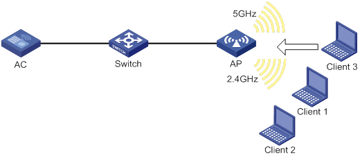
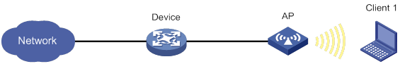
About band navigation
As shown in Figure 4, band navigation is enabled in the WLAN. Client 1 and Client 2 are associated with the 2.4 GHz radio. When the dual-band client Client 3 requests to associate with the 2.4 GHz radio, the AP rejects Client 3 and directs it to the 5 GHz radio.
Feature and hardware compatibility
WLAN is supported only on the following routers:
· MSR810-W.
· MSR810-W-DB.
· MSR810-W-LM.
· 810-W-LM-HK.
· MSR810-W-LM-GL.
Restrictions and guidelines: band navigation configuration
Do not enable band navigation in a WLAN where most clients in the WLAN support only the 2.4 GHz band or in a WLAN that is sensitive to traffic delay.
Band navigation tasks at a glance
|
Tasks at a glance |
|
(Required.) Enabling band navigation globally |
|
(Optional.) Configuring load balancing for band navigation |
|
(Optional.) Configuring band navigation parameters |
Prerequisites for band navigation
Complete the following tasks before configuring band navigation:
· Disable quick association. For more information about quick association, see "Configuring WLAN access."
· Enable both the 5 GHz and 2.4 GHz radios and bind the radios to the same service template.
Enabling band navigation globally
|
Step |
Command |
Remarks |
|
1. Enter system view. |
system-view |
N/A |
|
2. Enable band navigation globally. |
wlan band-navigation enable |
By default, band navigation is disabled globally. |
Configuring load balancing for band navigation
About load balancing for band navigation
An AP rejects the 5 GHz association request of a client when the following conditions are met:
· The number of clients on the 5 GHz radio reaches the specified threshold.
· The client number gap between the 5 GHz radio and the radio that has the fewest clients reaches the specified threshold.
Procedure
|
Step |
Command |
Remarks |
|
1. Enter system view. |
system-view |
N/A |
|
2. Configure load balancing for band navigation. |
wlan band-navigation balance session session [ gap gap ] |
By default, load balancing is disabled for band navigation. |
Configuring band navigation parameters
About band navigation parameters
The following parameters affect band navigation:
· Maximum number of denials for 5 GHz association requests—If the number of times that a 5 GHz radio rejects a client reaches the specified maximum number, the radio accepts the association request of the client.
· Band navigation RSSI threshold—A client might be detected by multiple radios. A 5 GHz radio rejects the association request of a client if the client's RSSI is lower than the band navigation RSSI threshold.
· Client information aging time—When an AP receives an association request from a client, the AP records the client's information and starts the client information aging timer. If the AP does not receive any probe requests or association requests from the client before the aging timer expires, the AP deletes the client's information.
Configure an appropriate client information aging time to ensure both client association and system resource efficiency.
Procedure
|
Step |
Command |
Remarks |
|
1. Enter system view. |
system-view |
N/A |
|
2. Set the maximum number of denials for 5 GHz association requests. |
wlan band-navigation balance access-denial access-denial |
By default, the maximum number of denials is 1 for 5 GHz association requests. |
|
3. Set the band navigation RSSI threshold. |
wlan band-navigation rssi-threshold rssi-threshold |
By default, the band navigation RSSI threshold is 15. |
|
4. Set the client information aging time. |
wlan band-navigation aging-time aging-time |
By default, the client information aging time is 180 seconds. |
Band navigation configuration examples
Example: Configuring band navigation
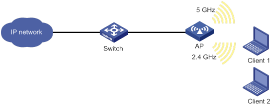
Network configuration
As shown in Figure 5, both the 5 GHz radio and the 2.4 GHz radio are enabled on the fat AP. Configure band navigation and load balancing for band navigation to load balance the radios.
Procedure
# Create service template 1 and set its SSID to band-navigation.
<FAT AP> system-view
[FAT AP] wlan service-template 1
[FAT AP-wlan-st-1] ssid band-navigation
[FAT AP-wlan-st-1] service-template enable
[FAT AP-wlan-st-1] quit
# Enter interface view of WLAN-Radio 1/0/1, and set the radio type to 802.11n (5 GHz).
[FAT AP] interface wlan-radio 1/0/1
[FAT AP-WLAN-Radio1/0/1] type dot11an
# Bind service template 1 to WLAN-Radio 1/0/1.
[FAT AP-WLAN-Radio1/0/1] service-template 1
[FAT AP-WLAN-Radio1/0/1] quit
# Enter interface view of WLAN-Radio 1/0/2, and set the radio type to 802.11n (2.4 GHz).
[FAT AP] interface wlan-radio 1/0/2
[FAT AP-WLAN-Radio1/0/2] type dot11gn
# Bind service template 1 to WLAN-Radio 1/0/2.
[FAT AP-WLAN-Radio1/0/2] service-template 1
[FAT AP-WLAN-Radio1/0/2] quit
# Enable band navigation globally.
[FAT AP] wlan band-navigation enable
# Enable load balancing for band navigation, and set the client number threshold and client number gap threshold to 5 and 2, respectively.
[FAT AP] wlan band-navigation balance session 5 gap 2
# Set the maximum number of denials for 5 GHz association requests to 3.
[FAT AP] wlan band-navigation balance access-denial 3
# Set the band navigation RSSI threshold to 30.
[FAT AP] wlan band-navigation rssi-threshold 30
# Set the client information aging time to 160 seconds.
[FAT AP] wlan band-navigation aging-time 160
Verifying the configuration
1. Verify that a dual-band client is associated with the 5 GHz radio when it requests to associate with the AP. (Details not shown.)
2. Verify that a dual-band client is associated with the 2.4 GHz radio when the following conditions are met:
? The number of clients on the 5 GHz radio reaches 5.
? The client number gap between the 5 GHz radio and the 2.4 GHz radio reaches 2. (Details not shown.)
Configuring WLAN access
The term "AP" in this document refers to MSR routers that support WLAN.
About WLAN access
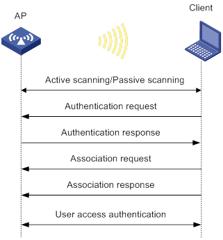
A wireless client can access a WLAN only when it completes the scanning, link layer authentication, association, and WLAN authentication processes.
For more information about data link layer authentication, see "Configuring WLAN security."
For more information about WLAN authentication, see "Configuring WLAN authentication."
Figure 6 WLAN access process
Scanning
Active scanning
A wireless client periodically scans surrounding wireless networks by sending probe requests. It obtains network information from received probe responses. Based on whether a probe request carries an SSID, active scanning can be divided into the following types:
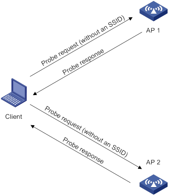
· Active scanning of all wireless networks.
As shown in Figure 7, the client periodically sends a probe request on each of its supported channels to scan wireless networks. APs that receive the probe request send a probe response that carries the available wireless network information. The client associates with the optimal AP.
Figure 7 Scanning all wireless networks
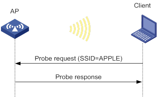
· Active scanning of a specific wireless network.
As shown in Figure 8, the client periodically sends a probe request carrying the specified SSID or the SSID of the wireless network it has been associated with. When an AP that can provide wireless services with the specified SSID receives the probe request, it sends a probe response.
Figure 8 Scanning a specific wireless network
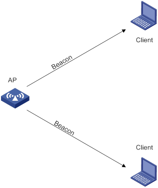
Passive scanning
As shown in Figure 9, the clients periodically listen for beacon frames sent by APs on their supported channels to get information about surrounding wireless networks. Then the clients select an AP for association. Passive scanning is used when clients want to save power.
Association
A client sends an association request to the associated AP after passing date link layer authentication. Upon receiving the request, the AP determines the capability supported by the wireless client and sends an association response to the client. Then the client is associated with the AP.
Whitelist- and blacklist-based access control
You can configure the whitelist or blacklists to filter frames from WLAN clients and implement client access control.
Whitelist-based access control
The whitelist contains the MAC addresses of all clients allowed to access the WLAN. Frames from clients not in the whitelist are discarded. This list is manually configured.
Blacklist-based access control
The following blacklists are available for access control:
· Static blacklist—Contains the MAC addresses of clients forbidden to access the WLAN. This list is manually configured.
· Dynamic blacklist—Contains the MAC addresses of clients forbidden to access the WLAN. An AP adds the MAC address of a client forbidden to access the WLAN to the list when URL redirection is enabled for WLAN MAC authentication clients. The entries in the list are removed when the aging time expires. For more information about WLAN MAC authentication, see "Configuring WLAN authentication."
Working mechanism
When the AP receives an association request, the AP performs the following operations to determine whether to permit the client:
1. Searches the whitelist:
? If the client MAC address does not match any entries in the whitelist, the client is rejected.
? If a match is found, the client is permitted.
2. Searches the static and dynamic blacklists if no whitelist entries exist:
? If the client MAC address matches an entry in either blacklist, the client is rejected.
? If no match is found, or no blacklist entries exist, the client is permitted.
Figure 10 Whitelist- and blacklist-based access control
Feature and hardware compatibility
WLAN is supported only on the following routers:
· MSR810-W.
· MSR810-W-DB.
· MSR810-W-LM.
· MSR810-W-LM-HK.
· MSR810-W-LM-GL.
WLAN access tasks at a glance
Configuring wireless services
Configuring a service template
About service templates
A service template defines a set of wireless service attributes, such as SSID and authentication method.
Procedure
|
Step |
Command |
Remarks |
|
1. Enter system view. |
system-view |
N/A |
|
2. Create a service template. |
wlan service-template service-template-name |
By default, no service template exists. |
|
3. Assign clients coming online through the service template to the specified VLAN. |
vlan vlan-id |
By default, clients are assigned VLAN 1 after coming online through a service template. |
Configuring a description for a service template
|
Step |
Command |
Remarks |
|
1. Enter system view. |
system-view |
N/A |
|
2. Enter service template view. |
wlan service-template service-template-name |
N/A |
|
3. Configure a description for the service template. |
description text |
By default, no description is configured for a service template. |
Setting an SSID
About SSIDs
APs advertise SSIDs in beacon frames. If the number of clients in a BSS exceeds the limit or the BSS is unavailable, you can enable SSID-hidden to prevent clients from discovering the BSS. When SSID-hidden is enabled, the BSS hides its SSID in beacon frames and does not respond to broadcast probe requests. A client must send probe requests with the specified SSID to access the WLAN. This feature can protect the WLAN from being attacked.
Procedure
|
Step |
Command |
Remarks |
|
1. Enter system view. |
system-view |
N/A |
|
2. Enter service template view. |
wlan service-template service-template-name |
N/A |
|
3. Set an SSID for the service template. |
ssid ssid-name |
By default, no SSID is set for a service template. |
|
4. (Optional.) Enable SSID-hidden in beacon frames. |
beacon ssid-hide |
By default, beacon frames carry SSIDs. |
Setting the maximum number of associated clients for a service template
About setting the client quantity limit for a service template
Perform this task to limit the associated client quantity to avoid overload. When this feature is configured, new clients cannot access the WLAN when the maximum number is reached.
Procedure
|
Step |
Command |
Remarks |
|
1. Enter system view. |
system-view |
N/A |
|
2. Enter service template view. |
wlan service-template service-template-name |
N/A |
|
3. Set the maximum number of associated clients for the service template. |
client max-count max-number |
By default, the number of associated clients for a service template is not limited. |
Enabling a service template
|
Step |
Command |
Remarks |
|
1. Enter system view. |
system-view |
N/A |
|
2. Enter service template view. |
wlan service-template service-template-name |
N/A |
|
3. Enable the service template. |
service-template enable |
By default, a service template is disabled. |
Binding a service template to a radio interface
Restrictions and guidelines
You can bind a maximum of 16 service templates to a radio interface.
Procedure
|
Step |
Command |
Remarks |
|
1. Enter system view. |
system-view |
N/A |
|
2. Enter WLAN-Radio interface view. |
interface wlan-radio interface-number |
N/A |
|
3. Bind a service template to the radio interface. |
service-template service-template-name |
By default, a radio interface is not bound to any service templates. |
Configuring wireless client functions
Setting the client idle timeout
About the client idle timeout
If an online client does not send any frames to the associated AP before the client idle timeout timer expires, the AP logs off the client.
Procedure
|
Step |
Command |
Remarks |
|
1. Enter system view. |
system-view |
N/A |
|
2. Set the client idle timeout. |
wlan client idle-timeout timeout |
By default, the client idle timeout is 3600 seconds. |
Configuring client keepalive
About client keepalive
This feature enables an AP to send keepalive packets to clients at the specified interval to determine whether the clients are online. If the AP does not receive any replies from a client within three keepalive intervals, it logs off the client.
Procedure
|
Step |
Command |
Remarks |
|
1. Enter system view. |
system-view |
N/A |
|
2. Enable client keepalive and set the client keepalive interval. |
wlan client keep-alive interval |
By default, client keepalive is disabled. |
Enabling quick association
About quick association
Enabling load balancing or band navigation might affect client association efficiency. For delay-sensitive services or in an environment where load balancing and band navigation is not needed, you can enable quick association for a service template.
Quick association disables load balancing or band navigation on clients associated with the service template. The device will not balance traffic or perform band navigation even if these two features are enabled in the WLAN.
Procedure
|
Step |
Command |
Remarks |
|
1. Enter system view. |
system-view |
N/A |
|
2. Enter service template view. |
wlan service-template service-template-name |
N/A |
|
3. Enable quick association. |
quick-association enable |
By default, quick association is disabled. |
Setting the idle period before client reauthentication
About the idle period before client reauthentication
Set the idle period before client reauthentication to reduce reauthentication failures.
When URL redirection is enabled for WLAN MAC authentication clients, an AP logs off a client that has passed MAC authentication. At the next MAC authentication attempt, the client can pass MAC authentication and access the WLAN. With the idle period configured, the AP adds the client to the dynamic blacklist after logging off the client and the client entry ages out after the specified idle period.
Procedure
|
Step |
Command |
Remarks |
|
1. Enter system view. |
system-view |
N/A |
|
2. Set the idle period before client reauthentication. |
wlan client reauthentication-period [ period-value ] |
By default, the idle period is not configured. |
Specifying the method for the AP to process traffic from unknown clients
About unknown client traffic processing
Perform this task to configure an AP using the specified service template to drop data packets from unknown clients and deauthenticate these clients or to drop the packets only.
Procedure
|
Step |
Command |
Remarks |
|
1. Enter system view. |
system-view |
N/A |
|
2. Enter service template view. |
wlan service-template service-template-name |
N/A |
|
3. Specify the method for the AP to process traffic from unknown clients. |
unknown-client [ deauthenticate | drop ] |
By default, the AP drops packets from unknown clients and deauthenticates these clients. |
Performing a wireless link quality test
About wireless link quality tests
This feature enables an AP to test the quality of the link to a wireless client. The AP sends empty data frames to the client at each supported rate. Then it calculates link quality information such as RSSI, packet retransmissions, and RTT based on the responses from the client.
The timeout for a wireless link quality test is 10 seconds. If the wireless link test is not completed before the timeout expires, test results cannot be obtained.
Procedure
|
Command |
|
|
Perform wireless link quality test. |
wlan link-test mac-address |
Enabling the device to generate client logs in the specified format
About client log formats
The device supports client logs in the following formats:
· H3C—Logs AP name, radio ID, client MAC address, SSID, BSSID, and client online status. By default, the device generates client logs only in H3C format.
· normal—Logs AP MAC address, AP name, client IP address, client MAC address, SSID, and BSSID.
· sangfor—Logs AP MAC address, client IP address, and client MAC address.
This feature enables the device to generate client logs in normal or sangfor format and send the logs to the information center. Log destinations are determined by the information center settings. For more information about the information center, see Network Management and Monitoring Configuration Guide.
This feature does not affect generation of client logs in H3C format.
Procedure
|
Step |
Command |
Remarks |
|
1. Enter system view. |
system-view |
N/A |
|
2. Enable the device to generate client logs in the specified format. |
customlog format wlan { normal | sangfor } |
By default, the device generates client logs only in the H3C format. |
Configuring client access control
Adding a client to the whitelist
Restrictions and guidelines
When you add the first client to the whitelist, the system asks you whether to disconnect all online clients. Enter Y at the prompt to configure the whitelist.
Procedure
|
Step |
Command |
Remarks |
|
1. Enter system view. |
system-view |
N/A |
|
2. Add a client to the whitelist. |
wlan whitelist mac-address mac-address |
By default, no clients exist in the whitelist. |
Adding a client to the static blacklist
Restrictions and guidelines
You cannot add a client to both the whitelist and the static blacklist.
If the whitelist and blacklists are configured, only the whitelist takes effect.
Procedure
|
Step |
Command |
Remarks |
|
1. Enter system view. |
system-view |
N/A |
|
2. Add a client to the static blacklist. |
wlan static-blacklist mac-address mac-address |
By default, no clients exist in the static blacklist. |
Configuring the dynamic blacklist
About the dynamic blacklist
The AP adds the MAC address of a client forbidden to access the WLAN to the list when URL redirection is enabled for WLAN MAC authentication clients.
Restrictions and guidelines
Entries in the dynamic blacklist are removed when the aging timer expires.
The configured aging timer takes effect only on entries newly added to the dynamic blacklist.
If the whitelist and blacklists are configured, only the whitelist takes effect.
Procedure
|
Step |
Command |
Remarks |
|
1. Enter system view. |
system-view |
N/A |
|
2. Set the aging timer for dynamic blacklist entries. |
wlan dynamic-blacklist lifetime lifetime |
By default, the aging timer is 300 seconds. The aging timer for dynamic blacklist entries takes effect only on rogue client entries. |
Specifying a region code
About region codes
A region code determines characteristics such as available frequencies, available channels, and transmit power level. Set a valid region code before configuring an AP.
To prevent regulation violation caused by region code modification, lock the region code.
Procedure
|
Step |
Command |
Remarks |
|
1. Enter system view. |
system-view |
N/A |
|
2. Enter global configuration view. |
wlan global-configuration |
N/A |
|
3. Specify a region code. |
region-code code |
By default, the region code is CN. |
|
4. Lock the region code. |
region-code-lock enable |
By default, region codes are not locked. |
Disabling the AP from responding to broadcast probe requests
About broadcast probe request responses
Broadcast probe requests do not carry any SSIDs. Upon receiving a broadcast probe request, an AP responds with a probe response that carries service information for the AP.
This feature enables clients that send unicast probe requests to the AP to associate with the AP more easily.
Procedure
|
Step |
Command |
Remarks |
|
1. Enter system view. |
system-view |
N/A |
|
2. Disable the AP from responding to broadcast probe requests. |
undo wlan broadcast-probe reply |
By default, the AP responds to broadcast probe requests. |
Enabling SNMP notifications for WLAN access
About SNMP notifications
To report critical WLAN access events to an NMS, enable SNMP notifications for WLAN access. For WLAN access event notifications to be sent correctly, you must also configure SNMP as described in Network Management and Monitoring Configuration Guide.
Procedure
|
Step |
Command |
Remarks |
|
1. Enter system view. |
system-view |
N/A |
|
2. Enable SNMP notification for client access. |
snmp-agent trap enable wlan client |
By default, SNMP notifications are disabled for client access. |
|
3. Enable SNMP notification for client audit. |
snmp-agent trap enable wlan client-audit |
By default, SNMP notifications are disabled for client audit. |
Display and maintenance commands for WLAN access
Execute display commands in any view and the reset command in user view.
|
Task |
Command |
|
Display the number of online clients and channel information for each radio. |
display wlan ap all radio client-number |
|
Display the number of online clients at both 2.4 GHz and 5 GHz bands. |
display wlan ap all client-number |
|
Display service template information. |
display wlan service-template [ service-template-name ] [ verbose ] |
|
Display basic service set (BSS) information. |
display wlan bss { all | bssid bssid } [ verbose ] |
|
Display client information. |
display wlan client [ interface wlan-radio interface-number | mac-address mac-address | service-template service-template-name ] [ verbose ] |
|
Display information about client IPv6 addresses. |
display wlan client ipv6 |
|
Display client online duration. |
display wlan client online-duration [ verbose ] |
|
Display client status information. |
display wlan client status [ mac-address mac-address ] [ verbose ] |
|
Display client statistics or service template statistics. |
display wlan statistics { client [ mac-address mac-address ] | service-template service-template-name [ connect-history ] } |
|
Display whitelist entries. |
display wlan whitelist |
|
Display blacklist entries. |
display wlan blacklist { dynamic | static } |
|
Remove the specified client or all clients from the dynamic blacklist. |
reset wlan dynamic-blacklist [ mac-address mac-address ] |
|
Log off the specified client or all clients. |
reset wlan client { all | mac-address mac-address } |
|
Clear client statistics. |
reset wlan statistics client { all | mac-address mac-address } |
|
Clear service template statistics. |
reset wlan statistics service-template service-template-name |
WLAN access configuration examples
Example: Configuring WLAN access
Network requirements
As shown in Figure 11, the switch acts as the DHCP server to assign IP addresses to the AP and the client. The AP provides wireless services with SSID trade-off.
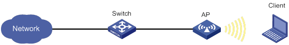
Configuration procedure
# Create service template service1, set the SSID to trade-off, and enable the service template.
<AP> system-view
[AP] wlan service-template service1
[AP-wlan-st-service1] ssid trade-off
[AP-wlan-st-service1] service-template enable
[AP-wlan-st-service1] quit
# Bind service template service1 to WLAN-Radio 1/0/1.
[AP] interface wlan-radio 1/0/1
[AP-WLAN-Radio1/0/1] undo shutdown
[AP-WLAN-Radio1/0/1] service-template service1
[AP-WLAN-Radio1/0/1] quit
Verifying the configuration
# Verify that the SSID is trade-off, and the service template is enabled.
[AP] display wlan service-template verbose
Service template name : service1
Description : Not configured
SSID : trade-off
SSID-hide : Disabled
User-isolation : Disabled
Service template status : Enabled
Maximum clients per BSS : Not configured
Frame format : Dot3
Seamless roam status : Disabled
Seamless roam RSSI threshold : 50
Seamless roam RSSI gap : 20
VLAN ID : 3
AKM mode : Not configured
Security IE : Not configured
Cipher suite : Not configured
TKIP countermeasure time : 0 s
PTK life time : 43200 s
GTK rekey : Enabled
GTK rekey method : Time-based
GTK rekey time : 86400 s
GTK rekey client-offline : Disabled
User authentication mode : Bypass
Intrusion protection : Disabled
Intrusion protection mode : Temporary-block
Temporary block time : 180 sec
Temporary service stop time : 20 sec
Fail VLAN ID : Not configured
Critical VLAN ID : Not configured
802.1X handshake : Disabled
802.1X handshake secure : Disabled
802.1X domain : my-domain
MAC-auth domain : Not configured
Max 802.1X users per BSS : 4096
Max MAC-auth users per BSS : 4096
802.1X re-authenticate : Disabled
Authorization fail mode : Online
Accounting fail mode : Online
Authorization : Permitted
Key derivation : SHA1
PMF status : Disabled
Hotspot policy number : Not configured
Forwarding policy status : Disabled
Forwarding policy name : Not configured
Forwarder : AC
FT status : Disabled
QoS trust : Port
QoS priority : 0
# Associate the client with the fat AP. (Details not shown.)
# Verify that the client can access the WLAN.
[AP] display wlan client service-template service1
Total number of clients: 1
MAC address Username AP name RID IP address IPv6 address VLAN
0023-8933-223b user ap1 1 3.0.0.3 3
Example: Configuring the whitelist
Network requirements
As shown in Figure 12, configure the whitelist to permit only the client whose MAC address is 0000-000f-1211 to access the WLAN.
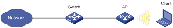
Configuration procedure
# Add MAC address 0000-000f-1211 to the whitelist.
<AP> system-view
[AP] wlan whitelist mac-address 0000-000f-1211
Verifying the configuration
# Verify that MAC address 0000-000f-1211 is in the whitelist.
<AP> display wlan whitelist
Total number of clients: 1
MAC addresses:
0000-000f-1211
Example: Configuring the static blacklist
Network requirements
As shown in Figure 13, configure the static blacklist to forbid the client whose MAC address is 0000-000f-1211 to access the WLAN.
Configuration procedure
# Add MAC address 0000-000f-1211 to the static blacklist.
<AP> system-view
[AP] wlan static-blacklist mac-address 0000-000f-1211
Verifying the configuration
# Verify that MAC address 0000-000f-1211 is in the static blacklist.
<AP> display wlan blacklist static
Total number of clients: 1
MAC addresses:
0000-000f-1211
Configuring WLAN security
The term "AP" in this document refers to MSR routers that support WLAN.
About WLAN security
WLAN security mechanisms include Pre Robust Security Network Association (Pre-RSNA), 802.11i, and 802.11w.
Pre-RSNA defines the original security mechanism, which is vulnerable to security attacks. To enhance WLAN security, 802.11i was introduced, but it encrypts only WLAN data traffic. Based on the 802.11i framework, 802.11w offers management frame protection to prevent attacks such as forged de-authentication and disassociation frames.
Pre-RSNA mechanism
The pre-RSNA mechanism uses the open system and shared key algorithms for authentication and uses WEP for data encryption. WEP uses the stream cipher RC4 for confidentiality and supports key sizes of 40 bits (WEP40), 104 bits (WEP104), and 128 bits (WEP128).
Open system authentication
Open system authentication is the default and simplest authentication algorithm. Any client that requests authentication by using this algorithm can pass the authentication.
Open system authentication uses the following process:
1. The client sends an authentication request to the AP.
2. The AP sends an authentication response to the client after the client passes the authentication.
Figure 14 Open system authentication process
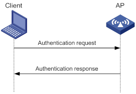
Shared key authentication
Shared key authentication uses a WEP key for the AP and client to complete authentication.
Shared key authentication uses the following process:
1. The client sends an authentication request to the AP.
2. The AP randomly generates a challenge text and sends it to the client.
3. The client uses the WEP key to encrypt the challenge text and sends it to the AP.
4. The AP uses the WEP key to decrypt the challenge text and compares the decrypted challenge text with the original challenge text. If they are identical, the client passes the authentication. If they are not, the authentication fails.
Figure 15 Shared key authentication process
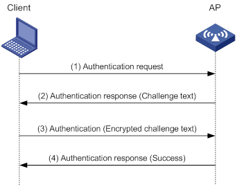
802.11i mechanism
|
|
IMPORTANT: 802.11i requires open system authentication for link layer authentication. |
Security modes
The 802.11i mechanism (the RSNA mechanism) provides WPA and RSN security modes. WPA implements a subset of an 802.11i draft to provide enhanced security over WEP and RSN implements the full 802.11i.
AKM
The 802.11i mechanism uses the following authentication and key management (AKM) modes for authenticating user integrity and dynamically generating and updating keys:
· 802.1X—802.1X performs user authentication and generates the pairwise master key (PMK) during authentication. The client and AP use the PMK to generate the pairwise transient key (PTK).
· Private PSK—The MAC address of the client is used as the PSK to generate the PMK. The client and AP use the PMK to generate the PTK.
· PSK—The PSK is used to generate the PMK. The client and AP use the PMK to generate the PTK.
Authentication
802.1X authentication is more secure than PSK authentication. For more information about 802.1X authentication, see "Configuring WLAN user access authentication."
PSK authentication requires the same PSK to be configured for both an AP and a client. PSK integrity is verified during the four-way handshake. If PTK negotiation succeeds, the client passes the authentication.
Key management
Key management defines how to generate and update the PTK and group temporary key (GTK). The PTK is used in unicast and the GTK is used in multicast and broadcast.
PTK and GTK
· PTK structure
![]()
? EAPOL-Key Confirmation Key (KCK) is used to verify the integrity of an EAPOL-Key frame.
? EAPOL-Key Encryption Key (KEK) is used to encrypt the key data in the EAPOL-Key frame.
? Temporal Key (TK) is used to encrypt unicast packets.
· The GTK includes the TK and other fields. The TK is used to encrypt multicast and broadcast packets.
EAPOL-Key packet
The IEEE 802.11i protocol uses EAPOL-Key packets during key negotiation.
Figure 16 EAPOL-Key structure
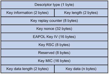
Table 12 EAPOL-Key field description
|
Field |
Description |
|
Descriptor type |
Specifies the network type: · WPA network. · RSN network. |
|
Key information |
For more information about this field, see Table 13. |
|
Key length |
Length of the key. |
|
Key replay counter |
Records the total number of GTK updates to prevent replay attacks. The AP sets this field to 0 at the beginning of the negotiation and increments the value on each successive EAPOL-Key frame. The client records this field from the last valid EAPOL-Key frame that it received if this field is greater than the field recorded previously. EAPOL-Key frame retransmission is required in the following situations: · The field received by the client is smaller than or equal to the field recorded by the client. · The field received by the AP is not equal to the field recorded on the AP. If the retransmission attempts exceed the maximum number, the AP disconnects the client. |
|
Key nonce |
Random value used to generate the PTK. |
|
EAPOL Key IV |
Encrypts the TKIP. This field is valid only when the encryption type is not CCMP. |
|
Key RSC |
Records the total number of multicast packets or broadcast packets to prevent replay attacks. The AP increments the value of this field on transmission of each multicast or broadcast packet. |
|
Reserved |
Reserved field. |
|
Key MIC |
Message integrity check. |
|
Key data length |
Length of the key data. |
|
Key data |
Data to be transmitted, such as the GTK and pairwise master key identifier (PMKID). |
Figure 17 Key information structure
![]()
Table 13 Key information description
|
Field |
Description |
|
Key Descriptor Version |
3-bit key version: · 1—Non-CCMP key. · 2—CCMP key. |
|
Key Type |
1-bit key type: · 0—Multicast negotiation key. · 1—Unicast negotiation key. |
|
Reserved |
2-bit field reserved. The sender sets this field to 0, and the receiver ignores this field. |
|
Install |
1-bit key installation field. If the Key Type field is 1, this field is 0 or 1. · 0—The AP does not request the client to install the TK. · 1—The AP requests the client to install the TK. If the Key type field is 0, the sender sets this field to 0, and the receiver ignores this field. |
|
Key Ack |
1-bit key acknowledgment field. The value 1 indicates that the AP requests an acknowledgement from the client. |
|
Key MIC |
Message integrity check. If this field is 1, the generated MIC must be included in the Key MIC field of the EAPOL-key frame. |
|
Secure |
1-bit key status. The value 1 indicates that the key has been generated. |
|
Error |
1-bit MIC check status. The value 1 indicates that a MIC failure has occurred. The client sets this field to 1 when the Request field is 1. |
|
Request |
1-bit request used by the client to request the AP to initiate the four-way handshake or multi-cast handshake in a MIC failure report. |
|
Encrypted Key Data |
1-bit key data encryption status. The value 1 indicates that the key data is encrypted. |
|
Reserved |
3-bit reserved field. The sender sets this field to 0, and the receiver ignores this field. |
WPA key negotiation
WPA uses EAPOL-Key packets in the four-way handshake to negotiate the PTK, and in the two-way handshake to negotiate the GTK.
Figure 18 WPA key negotiation process
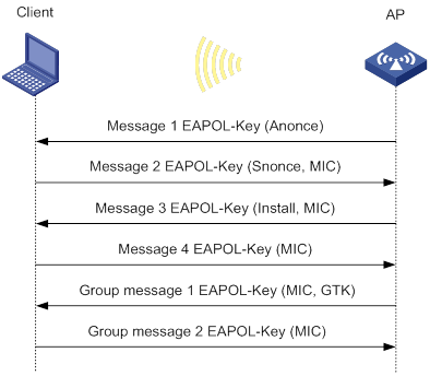
WPA key negotiation uses the following process:
1. The AP sends the client EAPOL-Key message 1 that contains a random value ANonce.
2. The client performs the following operations:
a. Uses the random value SNonce, ANonce, and PMK to generate a PTK by using the key derivation function (KDF).
b. Uses the KCK in the PTK to generate the MIC.
c. Returns EAPOL-Key message 2 that contains the SNonce and MIC.
3. The AP performs the following operations:
a. Uses the SNonce, ANonce, and PMK to generate a PTK by using the KDF.
b. Uses the KCK in the PTK to generate the MIC.
c. Compares the received MIC with the local MIC.
d. Returns EAPOL-Key message 3 that contains the PTK installation request tag and MIC if the two MICs are the same.
4. The client performs the following operations:
a. Compares the received MIC with the local MIC.
b. Installs the PTK and returns EAPOL-Key message 4 that contains the MIC if the two MICs are the same.
5. The AP performs the following operations:
a. Compares the received MIC with the local MIC.
b. Installs the PTK and generates a GTK with the GMK and MAC address of the AP by using the KDF if the two MICs are the same.
c. Returns EAPOL-Key group message 1 that contains the GTK and MIC.
6. The client performs the following operations:
a. Installs the GTK if the two MICs are the same.
b. Returns EAPOL-Key group message 2 that contains the MIC.
7. The AP performs the following operations:
a. Compares the received MIC with the local MIC.
b. Installs the GTK if the MICs are the same.
RSN key negotiation
RSN uses EAPOL-Key packets in the four-way handshake to negotiate the PTK and the GTK.
Figure 19 RSN key negotiation process
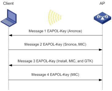
RSN key negotiation uses the following process:
1. The AP sends the client EAPOL-Key message 1 that contains a random value ANonce.
2. The client performs the following operations:
a. Uses the random value SNonce, ANonce, and PMK to generate a PTK by using the KDF.
b. Uses the KCK in the PTK to generate the MIC.
c. Returns EAPOL-Key message 2 that contains the SNonce and MIC.
3. The AP performs the following operations:
a. Uses the SNonce, ANonce, and PMK to generate a PTK by using the KDF.
b. Uses the KCK in the PTK to generate the MIC.
c. Compares the received MIC with the local MIC.
d. Generates a GTK with the random GMK and MAC address of the AP by using the KDF if the two MICs are the same.
e. Returns EAPOL-Key message 3 that contains the key installation request tag, MIC, and GTK.
4. The client performs the following operations:
a. Compares the received MIC with the local MIC.
b. Installs the PTK and GTK if the two MICs are the same.
c. Returns EAPOL-Key message 4 that contains the MIC.
5. The AP performs the following operations:
a. Compares the received MIC with the local MIC.
b. Installs the PTK and GTK if the two MICs are the same.
Key updates
Key updates enhance WLAN security. Key updates include PTK updates and GTK updates.
· PTK updates—Updates for the unicast keys using the four-way handshake negotiation.
· GTK updates—Updates for the multicast keys using the two-way handshake negotiation.
Cipher suites
TKIP
Temporal Key Integrity Protocol (TKIP) and WEP both use the RC4 algorithm. You can change the cipher suite from WEP to TKIP by updating the software without changing the hardware. TKIP has the following advantages over WEP:
· TKIP provides longer initialization vectors (IVs) to enhance encryption security. Compared with WEP encryption, TKIP encryption uses the 128-bit RC4 encryption algorithm, and increases the length of IVs from 24 bits to 48 bits.
· TKIP allows for dynamic key negotiation to avoid static key configuration. TKIP dynamic keys cannot be easily deciphered.
· TKIP offers MIC and countermeasures. If a packet has been tampered with, it will fail the MIC. If two packets fail the MIC in a period, the AP automatically takes countermeasures by stopping providing services in a period to prevent attacks.
CCMP
Counter mode with CBC-MAC Protocol (CCMP) is based on the Counter-Mode/CBC-MAC (CCM) of the Advanced Encryption Standard (AES) encryption algorithm.
CCMP contains a dynamic key negotiation and management method. Each client can dynamically negotiate a key suite, which can be updated periodically to further enhance the security of the CCMP cipher suite. During the encryption process, CCMP uses a 48-bit packet number (PN) to make sure each encrypted packet uses a different PN. This improves WLAN security.
Dynamic WEP mechanism
|
|
IMPORTANT: The dynamic WEP mechanism uses open system authentication for link layer authentication. |
802.11 provides the dynamic WEP mechanism to ensure that each user uses a private WEP key.
· For unicast communications, the mechanism uses the WEP key negotiated by the client and server during 802.1X authentication.
· For multicast and broadcast communications, the mechanism uses the configured WEP key. If you do not configure a WEP key, the AP randomly generates a WEP key for broadcast and multicast communications.
After the client passes 802.1X authentication, the AP sends the client an RC4-EAPOL packet that contains the unicast WEP key ID, and the multicast and broadcast WEP key and key ID. The unicast WEP key ID is 4.
802.11w management frame protection
About 802.11w management frame protection
The management frame protection service protects a set of robust management frames, such as de-authentication, disassociation, and some robust action frames.
· For unicast management frames, it uses the PTK to encrypt the frames and provides secrecy, integrity, and replay protection.
· For broadcast and multicast management frames, it uses the Broadcast Integrity Protocol (BIP) to provide integrity and replay protection.
The security association (SA) query mechanism is used to enhance security if the AP and client negotiate to use management frame protection. SA queries include active SA queries and passive SA queries.
Active SA query
As shown in Figure 20, active SA query uses the following process:
1. The client sends an association or reassociation request to the AP.
2. Upon receiving the request, the AP sends a response to inform the client that the request is denied and the client can associate at a later time. The response contains the association comeback time.
3. The AP sends an SA query request to verify the status of the client:
? If the AP receives an SA query response within the timeout time, it considers the client online.
? If the AP does not receive an SA query response within the timeout time, it sends another SA query request. If the AP receives an SA query response within the retransmission time, it considers the client online. The AP does not respond to any association or reassociation requests from the client until the association comeback time times out.
? If the AP does not receive an SA query response within the retransmission time, it considers the client offline and allows the client to reassociate.
Figure 20 Active SA query process
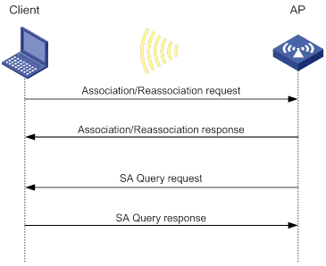
Passive SA query
As shown in Figure 21, passive SA query uses the following process:
1. The client triggers the SA query process upon receiving an unencrypted disassociation or deauthentication frame.
2. The client sends an SA query request to the AP.
3. The AP sends an SA query response to the client:
? If the client receives the response, the client determines that the AP is online and does not process the disassociation or deauthentication frame.
? If the client does not receive a response, the client determines that the AP is offline and disassociates with the AP.
Figure 21 Passive SA query process
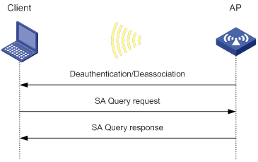
Protocols and standards
· IEEE Standard for Information technology—Telecommunications and information exchange between systems—Local and metropolitan area networks—Specific requirements—2004
· WI-FI Protected Access—Enhanced Security Implementation Based On IEEE P802.11i Standard-Aug 2004
· Information technology—Telecommunications and information exchange between systems—Local and metropolitan area networks—Specific requirements—802.11, 1999
· IEEE Standard for Local and metropolitan area networks "Port-Based Network Access Control" 802.1X™-2004
· 802.11i IEEE Standard for Information technology—Telecommunications and information exchange between systems—Local and metropolitan area networks—Specific requirements
· 802.11w IEEE Standard for Information technology—Telecommunications and information exchange between systems—Local and metropolitan area networks—Specific requirements
Feature and hardware compatibility
WLAN is supported only on the following routers:
· MSR810-W.
· MSR810-W-DB.
· MSR810-W-LM.
· MSR810-W-LM-HK.
WLAN security tasks at a glance
Pre-RSNA tasks at a glance
|
Tasks at a glance |
|
(Required.) Setting the cipher suite |
|
(Required.) Setting the WEP key |
|
(Optional.) Enabling SNMP notifications for WLAN security |
802.11i tasks at a glance
|
|
IMPORTANT: · 802.11i requires open system authentication for link layer authentication. · The AKM mode, security IE, and cipher suite must be configured for 802.11i networks. · Management frame protection takes effect only for a network that uses the 802.11i mechanism and is configured with the CCMP cipher suite and RSN security information element. |
|
Tasks at a glance |
|
(Required.) Configuring the AKM mode |
|
(Required.) Setting the security information element |
|
(Required.) Setting the cipher suite |
|
(Optional.) Setting the PSK |
|
(Optional.) Setting the KDF |
|
(Optional.) Configuring GTK update |
|
(Optional.) Configuring PTK update |
|
(Optional.) Setting the TKIP MIC failure hold time |
|
(Optional.) Setting the WEP key |
|
(Optional.) Configuring 802.11w management frame protection |
|
(Optional.) Enabling SNMP notifications for WLAN security |
Dynamic WEP tasks at a glance
|
Tasks at a glance |
|
(Optional.) Setting the cipher suite |
|
(Optional.) Setting the WEP key |
|
(Required.) Enabling the dynamic WEP mechanism |
|
(Optional.) Enabling SNMP notifications for WLAN security |
Configuring security features
Configuring the AKM mode
About AKM modes
Each of the following AKM modes must be used with a specific authentication mode:
· 802.1X AKM—802.1X authentication mode.
· Private PSK AKM—MAC authentication mode.
· PSK AKM—MAC or bypass authentication mode.
· WiFi alliance anonymous 802.1X AKM—802.1X authentication mode.
Procedure
|
Step |
Command |
Remarks |
|
1. Enter system view. |
system-view |
N/A |
|
2. Enter WLAN service template view. |
wlan service-template service-template-name |
N/A |
|
3. Configure the AKM mode. |
akm mode { dot1x | private-psk | psk | anonymous-dot1x } |
By default, no AKM mode is configured. |
Setting the security information element
About security information elements
Perform this task to enable an AP to set the security information element (security IE) bit in beacon and probe responses to notify clients of its security capabilities.
Procedure
|
Step |
Command |
Remarks |
|
1. Enter system view. |
system-view |
N/A |
|
2. Enter WLAN service template view. |
wlan service-template service-template-name |
N/A |
|
3. Set the security IE. |
security-ie { osen | rsn | wpa } |
By default, no security IE is set. |
Setting the cipher suite
About cipher suites
The following cipher suites are available:
· WEP (WEP40, WEP104, or WEP128).
· CCMP.
· TKIP.
Restrictions and guidelines
You cannot set both WEP 128 and CCMP or both WEP 128 and TKIP.
Procedure
|
Step |
Command |
Remarks |
|
1. Enter system view. |
system-view |
N/A |
|
2. Enter WLAN service template view. |
wlan service-template service-template-name |
N/A |
|
3. Set the cipher suite. |
cipher-suite { ccmp | tkip | wep40 | wep104 | wep128 } |
By default, no cipher suite is set. |
Setting the PSK
Restrictions and guidelines
The PSK must be set if the AKM mode is PSK. If you configure the PSK when the AKM mode is 802.1X, the WLAN service template can be enabled but the PSK configuration does not take effect.
Procedure
|
Step |
Command |
Remarks |
|
1. Enter system view. |
system-view |
N/A |
|
2. Enter WLAN service template view. |
wlan service-template service-template-name |
N/A |
|
3. Set the PSK. |
preshared-key { pass-phrase | raw-key } { cipher | simple } string |
By default, no PSK is set. |
Setting the KDF
About KDFs
KDFs are used by 802.11i networks to generate PTKs and GTKs. KDFs include HMAC-SHA1 and HMAC-SHA256 algorithms. The HMAC-SHA256 algorithm is more secure than the HMAC-SHA1 algorithm.
Procedure
|
Step |
Command |
Remarks |
|
1. Enter system view. |
system-view |
N/A |
|
2. Enter WLAN service template view. |
wlan service-template service-template-name |
N/A |
|
3. Set the KDF. |
key-derivation { sha1 | sha256 | sha1-and-sha256 } |
By default, the HMAC-SHA1 algorithm is set. |
Configuring GTK update
About GTK update
The system generates the GTK during key negotiation if the AKM, security IE, and cipher suite are configured. This feature updates the GTK to enhance key security based on the following updating modes:
· Time-based—The GTK is updated at the specified interval.
· Packet-based—The GTK is updated after the specified number of packets is sent.
· Offline-triggered—The GTK is updated when a client in the basic service set (BSS) goes offline.
Procedure
|
Step |
Command |
Remarks |
|
1. Enter system view. |
system-view |
N/A |
|
2. Enter WLAN service template view. |
wlan service-template service-template-name |
N/A |
|
3. Enable GTK update. |
gtk-rekey enable |
By default, GTK update is enabled. |
|
4. (Optional.) Configure a GTK update method. |
gtk-rekey method { packet-based [ packet ] | time-based [ time ] } |
By default, the GTK is updated at an interval of 85400 seconds. The default packet quantity is 10000000 for packet-based GTK update. |
|
5. (Optional.) Enable the offline-triggered GTK update. |
gtk-rekey client-offline enable |
By default, offline-triggered GTK update is disabled. |
Configuring PTK update
About PTK update
The system generates the PTK during key negotiation when the AKM, security IE, and cipher suite are configured. This feature updates the PTK after the PTK lifetime expires.
Procedure
|
Step |
Command |
Remarks |
|
1. Enter system view. |
system-view |
N/A |
|
2. Enter WLAN service template view. |
wlan service-template service-template-name |
N/A |
|
3. Enable PTK update. |
ptk-rekey enable |
By default, PTK update is enabled. |
|
4. Set the PTK lifetime. |
ptk-lifetime time |
By default, the PTK lifetime is 43200 seconds. |
Setting the TKIP MIC failure hold time
About the TKIP MIC failure hold time
After configuring the TKIP, you can configure the TKIP MIC failure hold time. If the AP detects two MIC failures within the MIC failure hold time, it disassociates all clients for 60 seconds.
Procedure
|
Step |
Command |
Remarks |
|
1. Enter system view. |
system-view |
N/A |
|
2. Enter WLAN service template view. |
wlan service-template service-template-name |
N/A |
|
3. Set the TKIP MIC failure hold time. |
tkip-cm-time time |
By default, the TKIP MIC failure hold time is 0. The AP does not take any countermeasures. |
Setting the WEP key
Restrictions and guidelines
The WEP key can be used to encrypt all packets for pre-RSNA networks and encrypt multicast packets for 802.11i networks. If the WEP key is not set, a pre-RSNA network does not encrypt packets and an 802.11i network uses the negotiated GTK to encrypt multicast packets.
Do not apply WEP key 4 if the dynamic WEP mechanism is enabled.
Procedure
|
Step |
Command |
Remarks |
|
1. Enter system view. |
system-view |
N/A |
|
2. Enter WLAN service template view. |
wlan service-template service-template-name |
N/A |
|
3. Set the WEP key. |
wep key key-id { wep40 | wep104 | wep128 } { pass-phrase | raw-key } { cipher | simple } string |
By default, no WEP key is set. |
|
4. (Optional.) Apply the WEP key. |
wep key-id { 1 | 2 | 3 | 4 } |
By default, WEP key 1 is applied. |
Configuring 802.11w management frame protection
About 802.11w management frame protection
When 802.11w management frame protection is disabled, network access is available for all clients, but management frame protection is not performed. When 802.11w management frame protection is enabled, network access and management frame protection availability varies by management frame protection mode.
· Optional mode—Network access is available for all clients, but management frame protection is performed only for clients that support management frame protection.
· Mandatory mode—Network access and management frame protection are available only for clients that support management frame protection.
Restrictions and guidelines
802.11w management frame protection takes effect only for a network that uses the 802.11i mechanism and is configured with the CCMP cipher suite and RSN security IE.
Procedure
|
Step |
Command |
Remarks |
|
1. Enter system view. |
system-view |
N/A |
|
2. Enter WLAN service template view. |
wlan service-template service-template-name |
N/A |
|
3. Enable management frame protection. |
pmf { optional | mandatory } |
By default, management frame protection is disabled. |
|
4. Set the interval for sending SA query requests. |
pmf saquery retrytimeout timeout |
By default, the interval for sending SA query requests is 200 milliseconds. |
|
5. Set the maximum transmission attempts for SA query requests. |
pmf saquery retrycount count |
By default, the maximum retransmission attempt number is 4 for SA query requests. |
|
6. Set the association comeback time. |
pmf association-comeback time |
By default, the association comeback time is 1 second. |
Enabling the dynamic WEP mechanism
About dynamic WEP
If dynamic WEP is enabled, the keys used for packet encryption depend on whether a WEP key is configured.
· If a WEP key is configured, the dynamic WEP mechanism uses the configured WEP key as the multicast and broadcast WEP key. The negotiated unicast WEP has an ID of 4 and uses the cipher suite length setting.
· If no WEP key is configured, the length for both dynamic WEP keys is 104 bits. The negotiated unicast WEP key has an ID of 4. The generated multicast and broadcast WEP key has an ID of 1.
Restrictions and guidelines
The dynamic WEP mechanism must be used with the 802.1X authentication mode.
Procedure
|
Step |
Command |
Remarks |
|
1. Enter system view. |
system-view |
N/A |
|
2. Enter WLAN service template view. |
wlan service-template service-template-name |
N/A |
|
3. Enable the dynamic WEP mechanism. |
wep mode dynamic |
By default, the dynamic WEP mechanism is disabled. |
Enabling SNMP notifications for WLAN security
About SNMP notifications
To report critical WLAN security events to an NMS, enable SNMP notifications for WLAN security. For WLAN security event notifications to be sent correctly, you must also configure SNMP as described in Network Management and Monitoring Configuration Guide.
Procedure
|
Step |
Command |
Remarks |
|
1. Enter system view. |
system-view |
N/A |
|
2. Enable SNMP notifications for WLAN security. |
snmp-agent trap enable wlan usersec |
By default, SNMP notifications are disabled for WLAN security. |
Display and maintenance commands for WLAN security
Execute display commands in any view.
|
Task |
Command |
|
Display client information. |
display wlan client [ interface interface-type interface-number | mac-address mac-address | service-template service-template-name ] [ verbose ] For more information about this command, see "WLAN access commands." |
|
Display WLAN service template information. |
display wlan service-template [ service-template-name ] [ verbose ] For more information about this command, see "WLAN access commands." |
WLAN security configuration examples
Example: Configuring shared key authentication
Network requirements
As shown in Figure 22, the switch functions as a DHCP server to assign IP addresses to the AP and client. Configure shared key authentication to enable the client to access the network by using WEP key 12345.
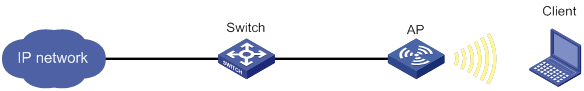
Configuration procedure
# Create a WLAN service template named service1.
<AP> system-view
[AP] wlan service-template service1
# Specify an SSID of service for the service template.
[AP-wlan-st-service1] ssid service
# Configure a WEP40 plaintext key of 12345 as WEP key 2, and apply WEP key 2.
[AP-wlan-st-service1] cipher-suite wep40
[AP-wlan-st-service1] wep key 2 wep40 pass-phrase simple 12345
[AP-wlan-st-service1] wep key-id 2
# Enable service template service1.
[AP-wlan-st-service1] service-template enable
[AP-wlan-st-service1] quit
# Bind service template service1 to radio interface WLAN-Radio 1/0/1 of the AP.
[AP] interface WLAN-Radio 1/0/1
[AP-WLAN-Radio1/0/1] undo shutdown
[AP-WLAN-Radio1/0/1] service-template service1
[AP-WLAN-Radio1/0/1] quit
Verifying the configuration
# Use the display wlan service-template command to verify that the WLAN service template has been configured correctly.
[AP] display wlan service-template service1 verbose
Service template name : service1
Description : Not configured
SSID : service
SSID-hide : Disabled
User-isolation : Disabled
Service template status : Enabled
Maximum clients per BSS : 64
Frame format : Dot3
Seamless roam status : Disabled
Seamless roam RSSI threshold : 50
Seamless roam RSSI gap : 20
VLAN ID : 1
AKM mode : Not configured
Security IE : Not configured
Cipher suite : WEP40
WEP key ID : 2
TKIP countermeasure time : 0
PTK lifetime : 43200 sec
PTK rekey : Enabled
GTK rekey : Enabled
GTK rekey method : Time-based
GTK rekey time : 86400 sec
GTK rekey client-offline : Enabled
User authentication mode : Shared-key
Intrusion protection : Disabled
Intrusion protection mode : Temporary-block
Temporary block time : 180 sec
Temporary service stop time : 20 sec
Fail VLAN ID : Not configured
802.1X handshake : Disabled
802.1X handshake secure : Disabled
802.1X domain : Not configured
MAC-auth domain : Not configured
Max 802.1X users per BSS : 4096
Max MAC-auth users per BSS : 4096
802.1X re-authenticate : Disabled
Authorization fail mode : Online
Accounting fail mode : Online
Authorization : Permitted
Key derivation : N/A
PMF status : Disabled
Hotspot policy number : Not configured
Forwarding policy status : Disabled
Forwarding policy name : Not configured
Forwarder : AP
FT status : Disabled
QoS trust : Port
QoS priority : 0
Example: Configuring PSK authentication and bypass authentication
Network requirements
As shown in Figure 23, the switch functions as a DHCP server to assign IP addresses to the AP and client.
· Configure open system authentication and bypass authentication.
· Configure the client to use preshared key 12345678 to access the network.
Configuration procedure
1. Create a WLAN service template named service1.
<AP> system-view
[AP] wlan service-template service1
2. Specify an SSID of service for the service template.
[AP-wlan-st-service1] ssid service
3. Configure WLAN security for service template service1:
# Configure the PSK AKM mode and the 12345678 plaintext key.
[AP-wlan-st-service1] akm mode psk
[AP-wlan-st-service1] preshared-key pass-phrase simple 12345678
# Configure CCMP as the cipher suite and WPA as the security IE.
[AP-wlan-st-service1] cipher-suite ccmp
[AP-wlan-st-service1] security-ie wpa
4. Enable service template service1.
[AP-wlan-st-service1] service-template enable
[AP-wlan-st-service1] quit
5. Bind service template service1 to radio interface WLAN-Radio 1/0/1 of the AP.
[AP] interface WLAN-Radio 1/0/1
[AP-WLAN-Radio1/0/1] undo shutdown
[AP-WLAN-Radio1/0/1] service-template service1
[AP-WLAN-Radio1/0/1] quit
Verifying the configuration
# Use the display wlan service-template command to verify that the WLAN service template has been configured correctly.
[AP] display wlan service-template service1 verbose
Service template name : service1
Description : Not configured
SSID : service
SSID-hide : Disabled
User-isolation : Disabled
Service template status : Enabled
Maximum clients per BSS : 64
Frame format : Dot3
Seamless roam status : Disabled
Seamless roam RSSI threshold : 50
Seamless roam RSSI gap : 20
VLAN ID : 1
AKM mode : PSK
Security IE : WPA
Cipher suite : CCMP
TKIP countermeasure time : 0
PTK lifetime : 43200 sec
PTK rekey : Enabled
GTK rekey : Enabled
GTK rekey method : Time-based
GTK rekey time : 86400 sec
GTK rekey client-offline : Enabled
User authentication mode : Bypass
Intrusion protection : Disabled
Intrusion protection mode : Temporary-block
Temporary block time : 180 sec
Temporary service stop time : 20 sec
Fail VLAN ID : Not configured
802.1X handshake : Disabled
802.1X handshake secure : Disabled
802.1X domain : Not configured
MAC-auth domain : Not configured
Max 802.1X users per BSS : 4096
Max MAC-auth users per BSS : 4096
802.1X re-authenticate : Disabled
Authorization fail mode : Online
Accounting fail mode : Online
Authorization : Permitted
Key derivation : N/A
PMF status : Disabled
Hotspot policy number : Not configured
Forwarding policy status : Disabled
Forwarding policy name : Not configured
Forwarder : AP
FT status : Disabled
QoS trust : Port
QoS priority : 0
Example: Configuring PSK authentication and MAC authentication
Network requirements
As shown in Figure 24, the switch functions as a DHCP server to assign IP addresses to the AP and client.
· Configure open system authentication and MAC authentication so that the client can access the network by using login username abc and password 123.
· Configure the client to use preshared key 12345678 to access the network.

Configuration procedure
1. Configure a username of abc and a password of 123 on the RADIUS server and make sure the RADIUS server and AP can reach each other. (Details not shown.)
2. Create a WLAN service template named service1.
<AP> system-view
[AP] wlan service-template service1
3. Specify an SSID of service for the service template.
[AP-wlan-st-service1] ssid service
4. Configure WLAN security for service template service1:
# Configure the PSK AKM mode and the 12345678 plaintext key.
[AP-wlan-st-service1] akm mode psk
[AP-wlan-st-service1] preshared-key pass-phrase simple 12345678
# Configure CCMP as the cipher suite and WPA as the security IE.
[AP-wlan-st-service1] cipher-suite ccmp
[AP-wlan-st-service1] security-ie wpa
# Configure the MAC-address-based authentication mode.
[AP-wlan-st-service1] client-security authentication-mode mac
5. Enable service template service1.
[AP-wlan-st-service1] service-template enable
[AP-wlan-st-service1] quit
6. Configure a RADIUS scheme:
# Create a RADIUS scheme named radius1 and enter its view.
[AP] radius scheme radius1
# Specify the primary authentication server and accounting server.
[AP-radius-radius1] primary authentication 10.1.1.3 1812
[AP-radius-radius1] primary accounting 10.1.1.3 1813
# Set the shared keys for authentication and accounting to 12345678 in plaintext.
[AP-radius-radius1] key authentication simple 12345678
[AP-radius-radius1] key accounting simple 12345678
# Configure the format for the usernames sent to the RADIUS server based on the RADIUS server configuration:
? Exclude domain names from the usernames sent to the RADIUS server.
[AP-radius-radius1] user-name-format without-domain
[AP-radius-radius1] quit
? Include domain names in the usernames sent to the RADIUS server.
[AP-radius-radius1] user-name-format with-domain
[AP-radius-radius1] quit
7. Create an ISP domain named dom1 and configure a RADIUS scheme for the ISP domain.
[AP] domain dom1
[AP-isp-dom1] authentication lan-access radius-scheme radius1
[AP-isp-dom1] authorization lan-access radius-scheme radius1
[AP-isp-dom1] accounting lan-access radius-scheme radius1
[AP-isp-dom1] quit
8. Configure an ISP domain of dom1, a username of abc, and a password of 123 for the user.
[AP] mac-authentication mac domain dom1
[AP] mac-authentication user-name-format fixed account abc password simple 123
9. Bind service template service1 to radio interface WLAN-Radio 1/0/1 of the AP.
[AP] interface WLAN-Radio 1/0/1
[AP-WLAN-Radio1/0/1] undo shutdown
[AP-WLAN-Radio1/0/1] service-template service1
[AP-WLAN-Radio1/0/1] quit
|
|
NOTE: For more information about the AAA and RADIUS commands in this section, see Security Command Reference. |
Verifying the configuration
# Use the display wlan service-template command to verify that the WLAN service template has been configured correctly.
[AP] display wlan service-template service1 verbose
Service template name : service1
Description : Not configured
SSID : service
SSID-hide : Disabled
User-isolation : Disabled
Service template status : Enabled
Maximum clients per BSS : 64
Frame format : Dot3
Seamless roam status : Disabled
Seamless roam RSSI threshold : 50
Seamless roam RSSI gap : 20
VLAN ID : 1
AKM mode : PSK
Security IE : WPA
Cipher suite : CCMP
TKIP countermeasure time : 0
PTK lifetime : 43200 sec
PTK rekey : Enabled
GTK rekey : Enabled
GTK rekey method : Time-based
GTK rekey time : 86400 sec
GTK rekey client-offline : Enabled
User authentication mode : MAC
Intrusion protection : Disabled
Intrusion protection mode : Temporary-block
Temporary block time : 180 sec
Temporary service stop time : 20 sec
Fail VLAN ID : Not configured
802.1X handshake : Disabled
802.1X handshake secure : Disabled
802.1X domain : Not configured
MAC-auth domain : Not configured
Max 802.1X users per BSS : 4096
Max MAC-auth users per BSS : 4096
802.1X re-authenticate : Disabled
Authorization fail mode : Online
Accounting fail mode : Online
Authorization : Permitted
Key derivation : N/A
PMF status : Disabled
Hotspot policy number : Not configured
Forwarding policy status : Disabled
Forwarding policy name : Not configured
Forwarder : AP
FT status : Disabled
QoS trust : Port
QoS priority : 0
Example: Configuring 802.1X AKM
Network requirements
As shown in Figure 25, the switch functions as a DHCP server to assign IP addresses to the AP and client.
· Configure open system authentication and 802.1X authentication so that the client can access the network by using login username abcdef and password 123456.
· Configure the 802.1X as the AKM mode.
Configuration procedure
1. Configure a username of abcdef and a password of 123456 on the RADIUS server and make sure the RADIUS server and AP can reach each other. (Details not shown.)
2. Configure the 802.1X client. (Details not shown.)
3. Create a WLAN service template named service1.
<AP> system-view
[AP] wlan service-template service1
4. Specify an SSID of service for the service template.
[AP-wlan-st-service1] ssid service
5. Configure WLAN security for service template service1:
# Configure 802.1X as the AKM mode.
[AP-wlan-st-service1] akm mode dot1x
# Configure CCMP as the cipher suite and WPA as the security IE.
[AP-wlan-st-service1] cipher-suite ccmp
[AP-wlan-st-service1] security-ie wpa
# Configure the 802.1X authentication mode.
[AP-wlan-st-service1] client-security authentication-mode dot1x
6. Enable service template service1.
[AP-wlan-st-service1] service-template enable
[AP-wlan-st-service1] quit
7. Configure a RADIUS scheme.
# Create a RADIUS scheme named radius1 and enter its view.
[AP] radius scheme radius1
# Specify the primary authentication server and accounting server.
[AP-radius-radius1] primary authentication 10.1.1.3 1812
[AP-radius-radius1] primary accounting 10.1.1.3 1813
# Set the shared keys for authentication and accounting to 12345 in plaintext.
[AP-radius-radius1] key authentication simple 12345
[AP-radius-radius1] key accounting simple 12345
# Configure the format for the usernames sent to the RADIUS server based on the RADIUS server configuration:
? Exclude domain names from the usernames sent to the RADIUS server.
[AP-radius-radius1] user-name-format without-domain
[AP-radius-radius1] quit
? Include domain names in the usernames sent to the RADIUS server.
[AP-radius-radius1] user-name-format with-domain
[AP-radius-radius1] quit
8. Create an ISP domain named dom1 and configure a RADIUS scheme for the ISP domain.
[AP] domain dom1
[AP-isp-dom1] authentication lan-access radius-scheme radius1
[AP-isp-dom1] authorization lan-access radius-scheme radius1
[AP-isp-dom1] accounting lan-access radius-scheme radius1
[AP-isp-dom1] quit
9. Configure ISP domain dom1 as the default ISP domain.
[AP] domain default enable dom1
10. Bind service template service1 to radio interface WLAN-Radio 1/0/1 of the AP.
[AP] interface WLAN-Radio 1/0/1
[AP-WLAN-Radio1/0/1] undo shutdown
[AP-WLAN-Radio1/0/1] service-template service1
[AP-WLAN-Radio1/0/1] quit
|
|
NOTE: For more information about the AAA and RADIUS commands in this section, see Security Command Reference. |
Verifying the configuration
# Use the display wlan service-template command to verify that the WLAN service template has been configured correctly.
[AP] display wlan service-template service1 verbose
Service template name : service1
Description : Not configured
SSID : service
SSID-hide : Disabled
User-isolation : Disabled
Service template status : Enabled
Maximum clients per BSS : 64
Frame format : Dot3
Seamless roam status : Disabled
Seamless roam RSSI threshold : 50
Seamless roam RSSI gap : 20
VLAN ID : 1
AKM mode : PSK
Security IE : WPA
Cipher suite : CCMP
TKIP countermeasure time : 0
PTK lifetime : 43200 sec
PTK rekey : Enabled
GTK rekey : Enabled
GTK rekey method : Time-based
GTK rekey time : 86400 sec
GTK rekey client-offline : Enabled
User authentication mode : 802.1X
Intrusion protection : Disabled
Intrusion protection mode : Temporary-block
Temporary block time : 180 sec
Temporary service stop time : 20 sec
Fail VLAN ID : Not configured
802.1X handshake : Disabled
802.1X handshake secure : Disabled
802.1X domain : Not configured
MAC-auth domain : Not configured
Max 802.1X users per BSS : 4096
Max MAC-auth users per BSS : 4096
802.1X re-authenticate : Disabled
Authorization fail mode : Online
Accounting fail mode : Online
Authorization : Permitted
Key derivation : N/A
PMF status : Disabled
Hotspot policy number : Not configured
Forwarding policy status : Disabled
Forwarding policy name : Not configured
Forwarder : AP
FT status : Disabled
QoS trust : Port
QoS priority : 0
Example: Configuring management frame protection
Network requirements
As shown in Figure 26, the switch functions as a DHCP server to assign IP addresses to the AP and client.
· Configure the client to use preshared key 12345678 to access the network.
· Configure the CCMP cipher suite, RSN security IE, and management frame protection.
Configuration procedure
1. Create a WLAN service template named service1.
<AP> system-view
[AP] wlan service-template service1
2. Specify an SSID of service for the service template.
[AP-wlan-st-service1] ssid service
3. Enable management frame protection in optional mode.
[AP-wlan-st-service1] pmf optional
4. Configure the 802.11i mechanism:
# Configure the PSK AKM mode and the 12345678 plaintext key.
[AP-wlan-st-service1] akm mode psk
[AP-wlan-st-service1] preshared-key pass-phrase simple 12345678
# Configure CCMP as the cipher suite and RSN as the security IE.
[AP-wlan-st-service1] cipher-suite ccmp
[AP-wlan-st-service1] security-ie rsn
5. Enable service template service1.
[AP-wlan-st-service1] service-template enable
[AP-wlan-st-service1] quit
6. Bind service template service1 to radio interface WLAN-Radio 1/0/1 of the AP.
[AP] interface WLAN-Radio 1/0/1
[AP-WLAN-Radio1/0/1] undo shutdown
[AP-WLAN-Radio1/0/1] service-template service1
[AP-WLAN-Radio1/0/1] quit
Verifying the configuration
# Use the display wlan service-template command to verify that the WLAN service template has been configured correctly.
[AP] display wlan service-template service1 verbose
Service template name : service1
Description : Not configured
SSID : service
SSID-hide : Disabled
User-isolation : Disabled
Service template status : Enabled
Maximum clients per BSS : 64
Frame format : Dot3
Seamless roam status : Disabled
Seamless roam RSSI threshold : 50
Seamless roam RSSI gap : 20
VLAN ID : 1
AKM mode : PSK
Security IE : RSN
Cipher suite : CCMP
TKIP countermeasure time : 0
PTK lifetime : 43200 sec
PTK rekey : Enabled
GTK rekey : Enabled
GTK rekey method : Time-based
GTK rekey time : 86400 sec
GTK rekey client-offline : Enabled
User authentication mode : Bypass
Intrusion protection : Disabled
Intrusion protection mode : Temporary-block
Temporary block time : 180 sec
Temporary service stop time : 20 sec
802.1X handshake : Disabled
802.1X handshake secure : Disabled
802.1X domain : Not configured
MAC-auth domain : Not configured
Max 802.1X users per BSS : 4096
Max MAC-auth users per BSS : 4096
802.1X re-authenticate : Disabled
Authorization fail mode : Online
Accounting fail mode : Online
Authorization : Permitted
Key derivation : SHA1-AND-SHA256
PMF status : Optional
Hotspot policy number : Not configured
Forwarding policy status : Disabled
Forwarding policy name : Not configured
Forwarder : AP
FT status : Disabled
QoS trust : Port
QoS priority : 0
# Use the display wlan client verbose command to verify the management frame protection negotiation results after a 802.11w client comes online.
[AP] display wlan client verbose
Total number of clients: 1
MAC address : 5250-0012-0411
Username : 11w
Radio ID : 1
SSID : service
BSSID : 1111-2222-3333
VLAN ID : 1
Power save mode : Active
Wireless mode : 802.11a
QoS mode : None
Listen interval : 100
RSSI : 0
Rx/Tx rate : 0/0
Authentication method : Open system
Security mode : RSN
AKM mode : PSK
Encryption cipher : CCMP
User authentication mode : Bypass
Authorization ACL ID : N/A
Authorization user profile : N/A
Roam status : Normal
Key derivation : SHA256
PMF status : Enabled
Online time : 0hr 0min 10sec
Example: Configuring dynamic WEP
Network requirements
As shown in Figure 27, the switch functions as a DHCP server to assign IP addresses to the AP and client.
· Configure open system authentication and 802.1X authentication so that the client can access the network by using login username abcdef and password 123456.
· Configure the dynamic WEP mechanism.
Configuration procedure
1. Configure a username of abcdef and a password of 123456 on the RADIUS server and make sure the RADIUS server and AP can reach each other. (Details not shown.)
2. Configure the 802.1X client. (Details not shown.)
3. Create a WLAN service template named service1.
<AP> system-view
[AP] wlan service-template service1
4. Specify an SSID of service for the service template.
[AP-wlan-st-service1] ssid service
5. Enable the dynamic WEP mechanism.
[AP-wlan-st-service1] wep mode dynamic
6. Configure the 802.1X authentication mode.
[AP-wlan-st-service1] client-security authentication-mode dot1x
7. Enable service template service1.
[AP-wlan-st-service1] service-template enable
[AP-wlan-st-service1] quit
8. Configure a RADIUS scheme:
# Create a RADIUS scheme named radius1 and enter its view.
[AP] radius scheme radius1
# Specify the primary authentication server and accounting server.
[AP-radius-radius1] primary authentication 10.1.1.3 1812
[AP-radius-radius1] primary accounting 10.1.1.3 1813
# Set the shared keys for authentication and accounting to 12345 in plaintext.
[AP-radius-radius1] key authentication simple 123456
[AP-radius-radius1] key accounting simple 123456
# Set the format for the usernames sent to the RADIUS server based on the RADIUS server configuration:
? Exclude domain names from the usernames sent to the RADIUS server.
[AP-radius-radius1] user-name-format without-domain
[AP-radius-radius1] quit
? Include domain names in the usernames sent to the RADIUS server.
[AP-radius-radius1] user-name-format with-domain
[AP-radius-radius1] quit
9. Create an ISP domain named dom1 and configure a RADIUS scheme for the ISP domain.
[AP] domain dom1
[AP-isp-dom1] authentication lan-access radius-scheme radius1
[AP-isp-dom1] authorization lan-access radius-scheme radius1
[AP-isp-dom1] accounting lan-access radius-scheme radius1
[AP-isp-dom1] quit
10. Configure ISP domain dom1 as the default ISP domain.
[AP] domain default enable dom1
11. Bind service template service1 to radio interface WLAN-Radio 1/0/1 of the AP.
[AP] interface WLAN-Radio 1/0/1
[AP-WLAN-Radio1/0/1] service-template service1
[AP-WLAN-Radio1/0/1] quit
|
|
NOTE: For more information about the AAA and RADIUS commands in this section, see Security Command Reference. |
Verifying the configuration
# Use the display wlan service-template command to verify that the WLAN service template has been configured correctly.
[AP] display wlan service-template service1 verbose
Service template name : service1
Description : Not configured
SSID : service
SSID-hide : Disabled
User-isolation : Disabled
Service template status : Enabled
Maximum clients per BSS : 64
Frame format : Dot3
Seamless roam status : Disabled
Seamless roam RSSI threshold : 50
Seamless roam RSSI gap : 20
VLAN ID : 1
AKM mode : Not configured
Security IE : Not configured
Cipher suite : WEP104
WEP key ID : 1
TKIP countermeasure time : 0
PTK lifetime : 43200 sec
PTK rekey : Enabled
GTK rekey : Enabled
GTK rekey method : Time-based
GTK rekey time : 86400 sec
GTK rekey client-offline : Enabled
User authentication mode : 802.1X
Intrusionprotection : Disabled
Intrusionprotection mode : Temporary-block
Temporary block time : 180 sec
Temporaryservicestop time : 20 sec
Fail VLAN ID : Not configured
802.1X handshake : Disabled
802.1X handshake secure : Disabled
802.1X domain : Not configured
MAC-auth domain : Not configured
Max 802.1X users per BSS : 4096
Max MAC-auth users per BSS : 4096
802.1X re-authenticate : Disabled
Authorization fail mode : Online
Accounting fail mode : Online
Authorization : Permitted
Key derivation : N/A
PMF status : Disabled
Hotspot policy number : Not configured
Forwarding policy status : Disabled
Forwarding policy name : Not configured
Forwarder : AP
FT status : Disabled
QoS trust : Port
QoS priority : 0
Example: Configuring private PSK authentication and MAC authentication
Network requirements
As shown in Figure 28, the switch functions as a DHCP server to assign IP addresses to the AP and client.
· Configure the MAC authentication mode so that the client can access the network by using its MAC address as the login username and password.
· Configure the private PSK AKM mode so that the client can use its MAC address as the PSK.

Configuration procedure
1. Configure a username of 00-23-12-45-67-7a and a password of 00-23-12-45-67-7a on the RADIUS server and make sure the RADIUS server and AP can reach each other. (Details not shown.)
2. Create a WLAN service template named service1.
<AP> system-view
[AP] wlan service-template service1
3. Specify an SSID of service for the service template.
[AP-wlan-st-service1] ssid service
4. Configure WLAN security for service template service1:
# Configure private PSK as the AKM mode.
[AP-wlan-st-service1] akm mode private-psk
# Configure CCMP as the cipher suite and WPA as the security IE.
[AP-wlan-st-service1] cipher-suite ccmp
[AP-wlan-st-service1] security-ie wpa
# Configure the MAC authentication mode.
[AP-wlan-st-service1] client-security authentication-mode mac
5. Enable service template service1.
[AP-wlan-st-service1] service-template enable
[AP-wlan-st-service1] quit
6. Configure a RADIUS scheme:
# Create a RADIUS scheme named radius1 and enter its view.
[AP] radius scheme radius1
# Specify the primary authentication server and accounting server.
[AP-radius-radius1] primary authentication 10.1.1.3 1812
[AP-radius-radius1] primary accounting 10.1.1.3 1813
# Set the shared keys for authentication and accounting to 12345678 in plaintext.
[AP-radius-radius1] key authentication simple 12345678
[AP-radius-radius1] key accounting simple 12345678
# Configure the format for the usernames sent to the RADIUS server based on the RADIUS server configuration:
? Exclude domain names from the usernames sent to the RADIUS server.
[AP-radius-radius1] user-name-format without-domain
[AP-radius-radius1] quit
? Include domain names in the usernames sent to the RADIUS server.
[AP-radius-radius1] user-name-format with-domain
[AP-radius-radius1] quit
7. Create an ISP domain named dom1 and configure a RADIUS scheme for the ISP domain.
[AP] domain dom1
[AP-isp-dom1] authentication lan-access radius-scheme radius1
[AP-isp-dom1] authorization lan-access radius-scheme radius1
[AP-isp-dom1] accounting lan-access radius-scheme radius1
[AP-isp-dom1] quit
8. Configure the MAC address as the username and password for ISP domain dom1.
[AP] mac-authentication domain dom1
[AP] mac-authentication user-name-format mac-address with-hyphen lowercase
9. Bind service template service1 to radio interface WLAN-Radio 1/0/1 of the AP.
[AP] interface WLAN-Radio 1/0/1
[AP-WLAN-Radio1/0/1] undo shutdown
[AP-WLAN-Radio1/0/1] service-template service1
[AP-WLAN-Radio1/0/1] quit
|
|
NOTE: For more information about the AAA and RADIUS commands in this section, see Security Command Reference. |
Verifying the configuration
# Use the display wlan service-template command to verify that the WLAN service template has been configured correctly.
[AP] display wlan service-template service1 verbose
Service template name : service1
Description : Not configured
SSID : service
SSID-hide : Disabled
User-isolation : Disabled
Service template status : Enabled
Maximum clients per BSS : 64
Frame format : Dot3
Seamless roam status : Disabled
Seamless roam RSSI threshold : 50
Seamless roam RSSI gap : 20
VLAN ID : 1
AKM mode : Private-PSK
Security IE : WPA
Cipher suite : CCMP
TKIP countermeasure time : 0
PTK lifetime : 43200 sec
PTK rekey : Enabled
GTK rekey : Enabled
GTK rekey method : Time-based
GTK rekey time : 86400 sec
GTK rekey client-offline : Enabled
User authentication mode : MAC
Intrusion protection : Disabled
Intrusion protection mode : Temporary-block
Temporary block time : 180 sec
Temporary service stop time : 20 sec
Fail VLAN ID : Not configured
802.1X handshake : Disabled
802.1X handshake secure : Disabled
802.1X domain : Not configured
MAC-auth domain : Not configured
Max 802.1X users per BSS : 4096
Max MAC-auth users per BSS : 4096
802.1X re-authenticate : Disabled
Authorization fail mode : Online
Accounting fail mode : Online
Authorization : Permitted
Key derivation : N/A
PMF status : Disabled
Hotspot policy number : Not configured
Forwarding policy status : Disabled
Forwarding policy name : Not configured
Forward policy : Not configured
Forwarder : AP
FT status : Disabled
QoS trust : Port
QoS priority : 0
Configuring WLAN authentication
About WLAN authentication
The term "AP" in this document refers to MSR routers that support WLAN.
This chapter describes H3C implementation of WLAN authentication. WLAN authentication performs MAC-based network access control for WLAN clients to ensure access security.
WLAN authentication includes the following authentication methods:
· 802.1X authentication—Uses Extensible Authentication Protocol (EAP) to transport authentication information for the client, the authenticator, and the authentication server.
· MAC authentication—Controls network access by authenticating source MAC addresses. The feature does not require any client software. Clients do not have to enter usernames or passwords for network access. The authenticator initiates a MAC authentication process when it detects an unknown source MAC address. If the MAC address passes authentication, the client can access authorized network resources. If the authentication fails, the authenticator marks the MAC address as a silent MAC address and rejects the client's access.
· OUI authentication—Examines the OUIs in the MAC addresses of clients. A client passes OUI authentication if the client's OUI matches one of the OUIs configured for the authenticator.
|
|
NOTE: An OUI is a 24-bit number that uniquely identifies a vendor, manufacturer, or organization. In MAC addresses, the first three octets are the OUI. |
Authentication modes
|
Authentication mode |
Working mechanism |
Whether intrusion protection can be triggered |
|
bypass (the default) |
Does not perform authentication. |
No |
|
dot1x |
Performs 802.1X authentication only. |
Yes |
|
mac |
Performs MAC authentication only. |
Yes |
|
mac-then-dot1x |
Performs MAC authentication first, and then 802.1X authentication. If the client passes MAC authentication, 802.1X authentication is not performed. |
Yes |
|
dot1x-then-mac |
Performs 802.1X authentication first, and then MAC authentication. If the client passes 802.1X authentication, MAC authentication is not performed. |
Yes |
|
oui-then-dot1x |
Performs OUI authentication first, and then 802.1X authentication. If the client passes OUI authentication, 802.1X authentication is not performed. |
Yes |
802.1X authentication
For more information about 802.1X architecture, EAP relay, EAP termination, and EAP packet encapsulation, see Security Configuration Guide.
Authentication methods
You can perform 802.1X authentication on the authenticator (local authentication) or through a RADIUS server. For information about RADIUS authentication and local authentication, see AAA in Security Configuration Guide.
Authenticator
The fat AP acts as the authenticator to authenticate the client to control access to the WLAN.
EAP packet encapsulation
802.1X defines EAP over LAN (EAPOL) for passing EAP packets between the client and the authenticator over a WLAN. Between the authenticator and the authentication server, 802.1X delivers authentication information by using one of the following methods:
· Encapsulates EAP packets in RADIUS by using EAP over RADIUS (EAPOR), as described in "EAP relay."
· Extracts authentication information from the EAP packets and encapsulates the information in standard RADIUS packets, as described in "EAP termination."
For information about EAP packet encapsulation, see Security Configuration Guide.
EAP relay
In this mode, the authenticator uses EAPOR packets to send authentication information to the RADIUS server. The RADIUS server must support the EAP-Message and Message-Authenticator attributes.
Figure 29 shows the basic 802.1X authentication process in EAP relay mode In this example, EAP-MD5 is used.
Figure 29 802.1X authentication process in EAP relay mode
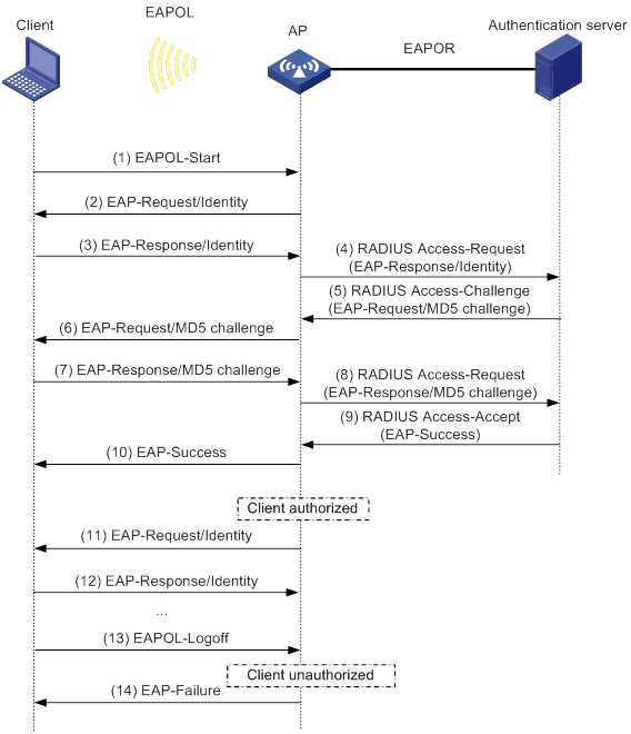
The following steps describe the 802.1X authentication process:
1. When a user launches the 802.1X client and enters a registered username and password, the 802.1X client sends an EAPOL-Start packet to the authenticator.
For information about the client and AP association, see "Configuring WLAN security."
2. The authenticator responds with an EAP-Request/Identity packet to request for the username.
3. The client sends the username in an EAP-Response/Identity packet to the authenticator.
4. The authenticator relays the EAP-Response/Identity packet in a RADIUS Access-Request packet to the authentication server.
6. The authenticator transmits the EAP-Request/MD5-Challenge packet to the client.
7. The client uses the received challenge to encrypt the password, and sends the encrypted password in an EAP-Response/MD5-Challenge packet to the authenticator.
8. The authenticator relays the EAP-Response/MD5-Challenge packet in a RADIUS Access-Request packet to the authentication server.
9. The authentication server compares the received encrypted password with the encrypted password it generated at step 5. If the two passwords are identical, the server considers the client valid and sends a RADIUS Access-Accept packet to the authenticator.
10. Upon receiving the RADIUS Access-Accept packet, the authenticator allows the client to access the network.
11. After the client comes online, the authenticator periodically sends handshake requests to examine whether the client is still online.
12. Upon receiving a handshake request, the client returns a response. If the client fails to return a response after a number of consecutive handshake attempts (two by default), the authenticator logs off the client. This handshake mechanism enables timely release of the network resources used by 802.1X clients that have abnormally gone offline.
13. The client sends an EAPOL-Logoff packet to request a logoff from the authenticator.
14. In response to the EAPOL-Logoff packet, the authenticator sends an EAP-Failure packet to the client.
EAP termination
In this mode, the authenticator performs the following operations:
1. Terminates the EAP packets received from the client.
2. Encapsulates the client authentication information in standard RADIUS packets.
3. Uses PAP or CHAP to communicate with the RADIUS server.
Figure 30 shows the basic 802.1X authentication process in EAP termination mode. In this example, CHAP authentication is used.
Figure 30 802.1X authentication process in EAP termination mode
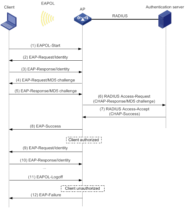
In EAP termination mode, the authentication device rather than the authentication server generates an MD5 challenge for password encryption. The authentication device then sends the MD5 challenge together with the username and encrypted password in a standard RADIUS packet to the RADIUS server.
802.1X authentication initiation
Both the client and the authenticator can initiate 802.1X authentication.
· Client initiation—After the client is associated with the authenticator, it sends an EAPOL-Start packet to the authenticator to initiate 802.1X authentication.
· Authenticator initiation—After the client is associated with the authenticator, the authenticator sends an EAP-Request/Identity packet to initiate the authentication. The authenticator retransmits the packet if no response has been received within the client timeout timer.
MAC authentication
Authentication methods
You can perform MAC authentication on the authenticator (local authentication) or through a RADIUS server. For information about RADIUS authentication and local authentication, see AAA in Security Configuration Guide.
Authenticator
The fat AP acts as the authenticator to authenticate the client to control access to the WLAN.
User account policies
User accounts are required for identifying clients. MAC authentication supports the following user account policies:
· One MAC-based user account for each client. The authenticator uses the unknown source MAC addresses in packets as the usernames and passwords of clients for MAC authentication.
· One shared user account for all clients. You specify one username and password, which are not necessarily a MAC address, for all MAC authentication clients on the authenticator. The username is a case-sensitive string of 1 to 55 characters which cannot include the at sign (@). The password can be a plaintext string of 1 to 63 characters or ciphertext string of 1 to 117 characters.
MAC authentication procedures
RADIUS authentication:
· MAC-based accounts—The authenticator sends the source MAC address of the packet as the username and password to the RADIUS server for authentication.
· A shared account—The authenticator sends the shared account username and password to the RADIUS server for authentication.
Local authentication:
· MAC-based accounts—The authenticator uses the source MAC address of the packet as the username and password to search the local account database for a match.
· A shared account—The authenticator uses the shared account username and password to search the local account database for a match.
Intrusion protection
When the authenticator detects an association request from a client that fails authentication, intrusion protection is triggered. The feature takes one of the following predefined actions on the BSS where the request is received:
· temporary-block (default)—Adds the source MAC address of the request to the blocked MAC address list and drops the request packet. The client at a blocked MAC address cannot establish connections with the AP within a period. To set the period, use the client-security intrusion-protection timer temporary-block command.
· service-stop—Stops the BSS where the request is received until the BSS is enabled manually on the radio interface.
· temporary-service-stop—Stops the BSS where the request is received for a period. To set the period, use the client-security intrusion-protection timer temporary-service-stop command.
|
|
NOTE: Intrusion protection action is not supported in bypass mode. |
WLAN VLAN manipulation
VLAN authorization
You can specify authorization VLANs for a WLAN client to control the client's access to network resources. When the client passes 802.1X or MAC authentication, the authentication server assigns the authorization VLAN information to the authenticator. When the device acts as the authenticator, it can resolve server-assigned VLANs of the following formats:
· VLAN ID.
· VLAN name.
The VLAN name represents the VLAN description on the access device.
· VLAN group name.
For more information about VLAN groups, see Layer 2—LAN Switching Configuration Guide.
· Combination of VLAN IDs and VLAN names.
In the string, some VLANs are represented by their IDs, and some VLANs are represented by their names.
If the server assigns a group of VLANs, the access device selects and assigns a VLAN according to the VLAN ID format. Table 14 describes the VLAN selection and assignment rules for a group of authorization VLANs.
Table 14 VLAN selection and assignment for a group of authorization VLANs
|
Types of authorized VLANs |
VLAN selection and assignment rules |
|
· VLANs by IDs · VLANs by names · Combination of VLAN IDs and VLAN names |
The device selects the VLAN with the lowest ID from the group of VLANs. |
|
VLAN group name |
1. The device selects the VLAN that has the fewest number of online users. 2. If multiple VLANs have the same number of online 802.1X users, the device selects the VLAN with the lowest ID. |
|
|
NOTE: The device converts VLAN names and VLAN group names into VLAN IDs before it assigns a VLAN to the client. |
The device fails VLAN authorization for a client in the following situations:
· The device fails to resolve the authorization VLAN information.
· The server assigns a VLAN name to the device, but the device does not have any VLAN using the name.
· The server assigns a VLAN group name to the device, but the VLAN group does not exist or the VLAN group has not been assigned any VLAN.
Authorization VLAN information is used to control data forwarding, so they must be assigned by the device that forwards data traffic. VLAN assignment can be local VLAN assignment or remote VLAN assignment, depending on whether the authenticator and the forwarding device are the same device.
· Local VLAN assignment—The authenticator and the forwarding device are the same device. After the authenticator obtains the authorization VLAN information, it resolves the information and assigns the VLAN.
· Remote VLAN assignment—The authenticator and the forwarding device are different devices. After the authenticator obtains the authorization VLAN information, it sends the information to the remote forwarding device. The forwarding device then resolves the information and assigns the VLAN.
For more information about VLANs, see Layer 2—LAN Switching Configuration Guide.
Auth-Fail VLAN
The WLAN Auth-Fail VLAN accommodates clients that have failed WLAN authentication because of the failure to comply with the organization security strategy. For example, the VLAN accommodates clients that have entered wrong passwords or usernames. The Auth-Fail VLAN does not accommodate WLAN clients that have failed authentication for authentication timeouts or network connection issues.
Clients in the Auth-Fail VLAN can access a limited set of network resources.
The authenticator reauthenticates a client in the Auth-Fail VLAN at the interval of 30 seconds.
· If the client passes the reauthentication, the authenticator assigns the client to the authorization VLAN. If no authorization VLAN is configured, the client is assigned to the initial VLAN.
· If the client fails the reauthentication, the client is still in the Auth-Fail VLAN.
Clients that use RSNA cannot be assigned to the Auth-Fail VLAN after they fail 802.1X authentication. The authenticator directly logs off the clients.
The Auth-Fail VLAN feature takes precedence over intrusion protection. When a client fails authentication, the Auth-Fail VLAN setting applies first. If no Auth-Fail VLAN is configured, the intrusion protection feature takes effect. If neither feature is configured, the authenticator directly logs off the client.
ACL assignment
You can specify an ACL for an 802.1X or MAC authentication client to control the client's access to network resources. After the client passes authentication, the authentication server assigns the ACL to the client for filtering traffic for this client. The authentication server can be on the AP that acts as the authenticator or on a RADIUS server. In either case, you must configure rules for the ACL on the authenticator.
To change the access control criteria for the client, you can use one of the following methods:
· Modify the ACL rules on the authenticator.
· Specify another ACL for the client on the authentication server.
For more information about ACLs, see ACL and QoS Configuration Guide.
User profile assignment
You can specify a user profile for a WLAN client to control the client's access to network resources. After the client passes 802.1X or MAC authentication, the authentication server assigns the user profile to the client for filtering traffic. The authentication server can be on the AP that acts as the authenticator or on a RADIUS server. In either case, you must configure the user profile on the authenticator.
To change the client's access permissions, you can use one of the following methods:
· Modify the user profile configuration on the authenticator.
· Specify another user profile for the client on the authentication server.
For more information about user profiles, see Security Configuration Guide.
BYOD access control
This feature allows the RADIUS server to push different register pages and assign different authorization attributes to clients on different endpoint devices.
|
|
NOTE: This feature supports only IMC servers to act as the RADIUS server at the current version. |
The following process illustrates the BYOD access control for a WLAN client that passes 802.1X or MAC authentication:
1. The authenticator performs the following operations:
a. Obtains the Option 55 attribute from DHCP packets.
b. Delivers the Option 55 attribute to the RADIUS server.
On an IMC server, the Option 55 attribute will be delivered to UAM.
2. The BYOD-capable RADIUS server performs the following operations:
a. Uses the Option 55 attribute to identify endpoint device information including endpoint type, operating system, and vendor.
b. Sends a register page and assigns authorization attributes to the client according to the device information.
Feature and hardware compatibility
WLAN is supported only on the following routers:
· MSR810-W.
· MSR810-W-DB.
· MSR810-W-LM.
· MSR810-W-LM-HK.
· MSR810-W-LM-GL.
WLAN authentication tasks at a glance
Prerequisites for WLAN authentication
802.1X configuration prerequisites
Before you configure 802.1X authentication, complete the following tasks:
· Configure an ISP domain and AAA scheme (local or RADIUS authentication) for 802.1X users. For more information, see AAA in Security Configuration Guide.
· If RADIUS authentication is used, create user accounts on the RADIUS server.
· If local authentication is used, create local user accounts on the access device and set the service type to lan-access.
MAC authentication configuration prerequisites
Before you configure MAC authentication, configure an ISP domain and specify an AAA method. For more information, see AAA in Security Configuration Guide.
· For local authentication, you must also create local user accounts (including usernames and passwords) and specify the lan-access service for local users.
· For RADIUS authentication, make sure the device and the RADIUS server can reach each other and create user accounts on the RADIUS server. If you are using MAC-based accounts, make sure the username and password for each account are the same as the MAC address of each MAC authentication user.
Configuring global WLAN authentication parameters
Setting OUIs for OUI authentication
About setting OUI values for OUI authentication
Perform this task only for the oui-then-dot1x authentication mode.
Restrictions and guidelines
The device supports a maximum of 16 OUIs.
Procedure
|
Step |
Command |
Remarks |
|
1. Enter system view. |
system-view |
N/A |
|
2. Set OUI values for OUI authentication. |
By default, no OUI values are set for OUI authentication. For more information about this command, see Security Command Reference. |
Enabling EAP relay or EAP termination for 802.1X authentication
Restrictions and guidelines
If EAP relay mode is used, the following restrictions and guidelines apply:
· The user-name-format command in RADIUS scheme view does not take effect. The device sends the authentication data from the client to the server without any modification. For information about the user-name-format command, see Security Command Reference.
· Make sure the RADIUS server use the same authentication method as the client. For the authenticator, you only need to use the dot1x authentication-method eap command to enable EAP relay.
Procedure
|
Step |
Command |
Remarks |
|
1. Enter system view. |
system-view |
N/A |
|
2. Enable EAP relay or EAP termination. |
dot1x authentication-method { chap | eap | pap } |
By default, the device performs EAP termination and uses CHAP to communicate with the RADIUS server. For more information about this command, see Security Command Reference. |
Specifying 802.1X-supported domain name delimiters
|
Step |
Command |
Remarks |
|
1. Enter system view. |
system-view |
N/A |
|
2. Specify a set of domain name delimiters for 802.1X clients. |
dot1x domain-delimiter string |
By default, only the at sign (@) delimiter is supported. For more information about this command, see Security Command Reference. |
Setting the maximum number of 802.1X authentication request attempts
|
Step |
Command |
Remarks |
|
1. Enter system view. |
system-view |
N/A |
|
2. Set the maximum number of attempts for sending an 802.1X authentication request. |
dot1x retry max-retry-value |
The default setting is 2. For more information about this command, see Security Command Reference. |
Setting the 802.1X authentication timers
About 802.1X authentication timers
802.1X uses the following timers to control interactions with the client and the RADIUS server:
· Client timeout timer—Starts when the device sends an EAP-Request/MD5-Challenge packet to a client. If the device does not receive a response when this timer expires, it retransmits the request to the client. If the device has made the maximum transmission attempts without receiving a response, the client fails authentication. To set the maximum attempts, use the dot1x retry command.
· Server timeout timer—Starts when the device sends a RADIUS Access-Request packet to the authentication server. If the device does not receive a response when this timer expires, the device retransmits the request to the server.
· Handshake timer—Starts after a client passes authentication when the online user handshake is enabled. The device sends handshake messages to the client at every handshake interval. The device logs off the client if it does not receive any response from the client after the maximum handshake attempts. To set the maximum attempts, use the dot1x retry command.
· Periodic reauthentication timer—Starts after a client passes authentication when periodic online user reauthentication is enabled. The device reauthenticates the client at the configured interval. Any change to the timer takes effect only on clients that come online after the change.
Restrictions and guidelines
In most cases, the default settings are sufficient. You can edit the timers, depending on the network conditions. The following are two examples:
· In a low-speed network, increase the client timeout timer.
· In a network with authentication servers of different performances, adjust the server timeout timer.
Procedure
|
Step |
Command |
Remarks |
|
1. Enter system view. |
system-view |
N/A |
|
2. Set the client timeout timer. |
dot1x timer supp-timeout supp-timeout-value |
The default setting is 30 seconds. For more information about this command, see Security Command Reference. |
|
3. Set the server timeout timer. |
dot1x timer server-timeout server-timeout-value |
The default setting is 100 seconds. For more information about this command, see Security Command Reference. |
|
4. Set the handshake timer. |
The default setting is 15 seconds. For more information about this command, see Security Command Reference. |
|
|
5. Set the periodic reauthentication timer. |
The default setting is 3600 seconds. For more information about this command, see Security Command Reference. |
Configuring the MAC authentication user account format
|
Step |
Command |
Remarks |
|
1. Enter system view. |
system-view |
N/A |
|
2. Configure the MAC authentication user account format. |
·
Use one MAC-based user account for each
client: ·
Use one shared user account for all
clients: |
By default, the device uses the MAC address of a client as the username and password for MAC authentication. The MAC address is in the hexadecimal notation without hyphens, and letters are in lower case. For more information about this command, see Security Command Reference. |
Specifying a global MAC authentication domain
About MAC authentication domain selection
MAC authentication chooses an ISP domain for WLAN clients in the following order:
1. The domain specified on the service template.
2. The global MAC authentication domain specified in system view.
3. The default domain.
Procedure
|
Step |
Command |
Remarks |
|
1. Enter system view. |
system-view |
N/A |
|
2. Specify an ISP domain for MAC authentication clients. |
By default, no ISP domain is specified for MAC authentication clients in system view. For more information about this command, see Security Command Reference. |
Setting the MAC authentication server timeout timer
About the MAC authentication server timeout timer
MAC authentication starts the server timeout timer when the device sends an authentication request to a RADIUS server. If the device does not receive any response from the RADIUS server within the timeout timer, the device regards the server unavailable. If the timer expires during MAC authentication, the client cannot access the network.
Procedure
|
Step |
Command |
Remarks |
|
1. Enter system view. |
system-view |
N/A |
|
2. Set the MAC authentication server timeout timer. |
mac-authentication timer server-timeout server-timeout-value |
The default setting is 100 seconds. For more information about this command, see Security Command Reference. |
Configuring service-specific WLAN authentication parameters
Setting the authentication mode
|
Step |
Command |
Remarks |
|
1. Enter system view. |
system-view |
N/A |
|
2. Enter service template view. |
N/A |
|
|
3. Set the authentication mode for WLAN clients. |
client-security authentication-mode { dot1x | dot1x-then-mac | mac | mac-then-dot1x | oui-then-dot1x } |
By default, the bypass mode applies. The device does not perform authentication. Clients can access the device directly. |
Specifying an EAP mode for 802.1X authentication
About specifying an EAP mode for 802.1X authentication
The EAP mode determines the EAP protocol provisions and packet format that the device uses to interact with clients.
802.1X supports the following EAP modes:
· extended—Requires the device to interact with clients according to the provisions and packet format defined by the H3C proprietary EAP protocol.
· standard—Requires the device to interact with clients according to the provisions and packet format defined by the standard EAP protocol.
Restrictions and guidelines
Perform this task only when an IMC server is used as the RADIUS server. Specify the extended mode for iNode clients, and specify the standard mode for other clients.
Procedure
|
Step |
Command |
Remarks |
|
1. Enter system view. |
system-view |
N/A |
|
2. Enter service template view. |
wlan service-template service-template-name |
N/A |
|
3. Specify an EAP mode for 802.1X authentication. |
dot1x eap { extended | standard } |
By default, the EAP mode is standard for 802.1X authentication. |
Ignoring 802.1X or MAC authentication failures
About ignoring 802.1X or MAC authentication failures
This feature applies to the following clients:
· Clients that use 802.1X authentication.
This feature enables the device to ignore the 802.1X authentication failures and allow clients that have failed 802.1X authentication to come online.
· Clients that use both RADIUS-based MAC authentication and portal authentication.
Typically, a WLAN client must pass MAC authentication and portal authentication in turn to access network resources. The client provides username and password each time portal authentication is performed.
This feature simplifies the authentication process for a client as follows:
? If the RADIUS server already records the client's MAC authentication information, the client passes MAC authentication. The device allows the client to access network resources without performing portal authentication.
? If the RADIUS server does not record the client's MAC authentication information, the client fails MAC authentication. The device ignores the MAC authentication failure and performs portal authentication for the client. If the client passes portal authentication, it can access network resources. The MAC address of the portal authenticated client will be recorded as MAC authentication information on the RADIUS server.
Restrictions and guidelines
For 802.1X clients that use RSN to roam to a new AP, do not configure this feature.
Procedure
|
Step |
Command |
Remarks |
|
1. Enter system view. |
system-view |
N/A |
|
2. Enter service template view. |
wlan service-template service-template-name |
N/A |
|
3. Configure the device to ignore 802.1X or MAC authentication failures. |
client-security ignore-authentication |
By default, the device does not ignore the authentication failures for wireless clients that perform 802.1X authentication or perform RADIUS-based MAC authentication. |
Enabling URL redirection for WLAN MAC authentication clients
About URL redirection
A client is allowed to pass RADIUS-based MAC authentication only when its credential information (username and password) and MAC address are recorded on the RADIUS server.
This feature facilitates MAC authentication for a client whose credential information and MAC address are not recorded on the RADIUS server. After this feature is enabled, RADIUS-based MAC authentication for the client proceeds as follows:
1. The RADIUS server assigns an authorization ACL and redirect URL after it receives the client's authentication request. The ACL denies the client's access to the external network.
2. The device redirects the client to the authentication page specified by the redirect URL when it receives the client's HTTP request.
3. On the authentication page, the client enters the username and password provided by the service provider to complete the Web authentication. The client's credential information and MAC address will be recorded.
4. After the client passes the Web authentication, the Web authentication server on the RADIUS server sends a DM request to log off the client.
For information about DMs, see AAA in Security Configuration Guide.
5. At the next MAC authentication attempt, the client can pass MAC authentication.
Restrictions and guidelines
This feature is applicable to scenarios where only RADIUS-based MAC authentication is used.
To cooperate with this feature, you must configure the authorization ACL and redirect URL for a client by following these restrictions and guidelines:
· The ACL must permit the client and the Web authentication server to exchange packets. For information about authorization ACLs, see MAC authentication in Security Configuration Guide.
· If the client uses DHCP to obtain a dynamic IP address, the ACL must permit the client and the DHCP server to exchange packets.
· You can configure other ACL rules as needed to filter packets.
· The redirect URL is the Web address that the client uses for Web authentication.
Procedure
|
Step |
Command |
Remarks |
|
1. Enter system view. |
system-view |
N/A |
|
2. Enter service template view. |
wlan service-template service-template-name |
N/A |
|
3. Enable URL redirection for WLAN authentication clients. |
client url-redirect enable |
By default, URL redirection is disabled for WLAN MAC authentication clients. |
Configuring a WLAN Auth-Fail VLAN
|
Step |
Command |
Remarks |
|
1. Enter system view. |
system-view |
N/A |
|
2. Enter service template view. |
N/A |
|
|
3. Configure a WLAN Auth-Fail VLAN. |
By default, no WLAN Auth-Fail VLAN exists. You can configure only one Auth-Fail VLAN for the service template. |
Ignoring authorization information from the server
About ignoring authorization information from the server
You can configure the device to ignore the authorization information received from the server (local or remote) after a client passes 802.1X or MAC authentication. Authorization information includes VLAN, ACL, and user profile information.
Procedure
|
Step |
Command |
Remarks |
|
1. Enter system view. |
system-view |
N/A |
|
2. Enter service template view. |
wlan service-template service-template-name |
N/A |
|
3. Ignore the authorization information received from the authentication server. |
By default, authorization information received from the authentication server is used. |
Enabling the authorization-fail-offline feature
About the authorization-fail-offline feature
The authorization-fail-offline feature logs off WLAN clients that fail ACL or user profile authorization.
A client fails ACL or user profile authorization in the following situations:
· The device or server fails to authorize the specified ACL or user profile to the client.
· The authorized ACL or user profile does not exist.
Restrictions and guidelines
This feature does not apply to clients that fail VLAN authorization. The device always logs off these clients.
Procedure
|
Command |
Remarks |
|
|
1. Enter system view. |
N/A |
|
|
2. Enter service template view. |
wlan service-template service-template-name |
N/A |
|
By default, this feature is disabled. The device does not log off clients that fail ACL or user profile authorization, and it outputs system logs. |
Configuring intrusion protection
About intrusion protection
This feature enables the device to take the predefined action on the BSS where an association request is received from a client that fails authentication. For more information, see "Intrusion protection."
Procedure
|
Step |
Command |
Remarks |
|
1. Enter system view. |
system-view |
N/A |
|
2. Enter service template view. |
wlan service-template service-template-name |
N/A |
|
3. Enable the intrusion protection feature. |
By default, intrusion protection is disabled. |
|
|
4. (Optional.) Configure the intrusion protection action. |
By default, temporary-block is used. |
|
|
5. (Optional.) Set the blocking period for illegal clients. |
client-security intrusion-protection timer temporary-block time |
The default setting is 180 seconds. |
|
6. (Optional.) Set the silence period during which the BSS remains disabled. |
client-security intrusion-protection timer temporary-service-stop time |
The default setting is 20 seconds. |
Configuring the online user handshake feature
About the online user handshake feature
The online user handshake feature examines the connectivity status of online 802.1X clients. The device sends handshake messages to online clients at the interval specified by the dot1x timer handshake-period command. If the device does not receive any responses from an online client after it has made the maximum handshake attempts, the device sets the client to offline state.
Procedure
|
Step |
Command |
Remarks |
|
1. Enter system view. |
system-view |
N/A |
|
2. Enter service template view. |
wlan service-template service-template-name |
N/A |
|
3. Enable the online user handshake feature. |
dot1x handshake enable |
By default, this feature is disabled. |
Configuring the online user handshake security feature
About the online user handshake security feature
The online user handshake security feature adds authentication information in the handshake messages. This feature can prevent illegal clients from forging legal 802.1X clients to exchange handshake messages with the device. With this feature, the device compares the authentication information in the handshake response message from a client with that assigned by the authentication server. If no match is found, the device logs off the client.
Restrictions and guidelines
To use the online user handshake security feature, make sure the online user handshake feature is enabled.
The online user handshake security feature protects only online authenticated 802.1X clients.
Procedure
|
Step |
Command |
Remarks |
|
1. Enter system view. |
system-view |
N/A |
|
2. Enter service template view. |
wlan service-template service-template-name |
N/A |
|
3. Enable the online user handshake feature. |
By default, this feature is disabled. |
|
|
4. Enable the online user handshake security feature. |
By default, this feature is disabled. |
Specifying an 802.1X authentication domain
About 802.1X authentication domain selection
802.1X authentication chooses an ISP domain for WLAN clients in the following order:
· The domain specified on the service template.
· The domain specified by username.
· The default domain.
Procedure
|
Step |
Command |
Remarks |
|
1. Enter system view. |
system-view |
N/A |
|
2. Enter service template view. |
wlan service-template service-template-name |
N/A |
|
3. Specify an 802.1X authentication domain for the service template. |
By default, no 802.1X authentication domain is specified for the service template. |
Setting the maximum number of concurrent 802.1X clients
About the maximum number of concurrent 802.1X clients
When the maximum number of concurrent 802.1X clients is reached for a service template, new 802.1X clients are rejected.
Procedure
|
Step |
Command |
Remarks |
|
1. Enter system view. |
system-view |
N/A |
|
2. Enter service template view. |
wlan service-template service-template-name |
N/A |
|
3. Set the maximum number of concurrent 802.1X clients for a service template. |
The default setting is 4096. |
Enabling the periodic online user reauthentication feature
About periodic online user reauthentication
Periodic online user reauthentication tracks the connection status of online clients, and updates the authorization attributes assigned by the server. The attributes include the ACL, VLAN, and user profile-based QoS. The reauthentication interval is user configurable.
The server-assigned session timeout timer (Session-Timeout attribute) and termination action (Termination-Action attribute) can affect the periodic online user reauthentication feature. To display the server-assigned Session-Timeout and Termination-Action attributes, use the display dot1x connection command (see Security Command Reference).
· If the termination action is Default (logoff), periodic online user reauthentication on the device takes effect only when the periodic reauthentication timer is shorter than the session timeout timer.
· If the termination action is Radius-request, the periodic online user reauthentication configuration on the device does not take effect. The device reauthenticates the online 802.1X clients after the session timeout timer expires.
Support for the assignment of Session-Timeout and Termination-Action attributes depends on the server model.
Procedure
|
Step |
Command |
Remarks |
|
1. Enter system view. |
system-view |
N/A |
|
2. Enter service template view. |
wlan service-template service-template-name |
N/A |
|
3. Enable periodic online user reauthentication. |
dot1x re-authenticate enable |
By default, this feature is disabled. |
Setting the maximum number of concurrent MAC authentication clients
About the maximum number of concurrent MAC authentication clients
When the maximum number of concurrent MAC authentication clients is reached for a service template, new MAC authentication clients are rejected.
Procedure
|
Step |
Command |
Remarks |
|
1. Enter system view. |
system-view |
N/A |
|
2. Enter service template view. |
wlan service-template service-template-name |
N/A |
|
3. Set the maximum number of concurrent MAC authentication clients for the service template. |
The default setting is 4096. |
Specifying a service-specific MAC authentication domain
About MAC authentication domain selection
MAC authentication chooses an ISP domain for WLAN clients in the following order:
· The domain specified on the service template.
· The global MAC authentication domain specified in system view.
· The default domain.
Procedure
|
Step |
Command |
Remarks |
|
1. Enter system view. |
system-view |
N/A |
|
2. Enter service template view. |
wlan service-template service-template-name |
N/A |
|
3. Specify an ISP domain for MAC authentication clients. |
mac-authentication domain domain-name |
By default, no ISP domain is specified for MAC authentication clients. |
Configuring the accounting-start trigger feature
About accounting-start trigger
This feature controls the device whether to send start-accounting requests to the accounting server for clients that use IP addresses of a specific type. The feature takes effect on clients that have passed 802.1X or MAC authentication. You can also set an accounting delay timer. The device can send start-accounting requests to the accounting server for 802.1X or MAC authenticated clients only when the delay timer expires for the clients. For more information about accounting, see AAA in Security Configuration Guide.
Restrictions and guidelines
To configure an IP address type to have the accounting-start qualification, you must enable learning for IP addresses of that type. For information about wireless client IP address learning, see "Configuring WLAN IP snooping."
If you configure the accounting-start trigger feature on a service template that has been enabled, the configuration takes effect only on subsequent clients. It does not affect clients that have been online since before the feature is configured.
Procedure
|
Step |
Command |
Remarks |
|
1. Enter system view. |
system-view |
N/A |
|
2. Enter service template view. |
wlan service-template service-template-name |
N/A |
|
3. Specify an IP address type to have the accounting-start qualification. |
client-security accounting-start trigger { ipv4 | ipv4-ipv6 | ipv6 | none } |
By default, only IPv4 addresses have the accounting-start qualification. |
|
4. (Optional.) Set the accounting delay. |
client-security accounting-delay time time [ no-ip-logoff ] |
By default, the device sends start-accounting requests for a client when it learns the required IP address of the client. |
Configuring the accounting-update trigger feature
About accounting-update trigger
This feature enables the device to send update-accounting requests to the accounting server for a client when the learned IP address of the client changes. The IP change-triggered accounting update facilitates precise accounting.
Restrictions and guidelines
This feature takes effect only when the accounting-start trigger feature takes effect.
This feature is independent of the periodic realtime accounting feature. For example, if you configure the accounting-update trigger as client IP addresses changing to IPv6 addresses and set the realtime accounting interval to 12 minutes, both settings take effect. For a client that uses the settings, the device sends update-accounting requests every 12 minutes and triggers accounting update whenever the client IP address changes to an IPv6 address. For more information about the realtime accounting interval, see AAA in Security Configuration Guide.
If you configure the accounting-update trigger feature on a service template that has been enabled, the configuration takes effect only on subsequent clients. It does not affect clients that have been online since before the feature is configured.
Procedure
To configure the accounting-update trigger feature:
|
Step |
Command |
Remarks |
|
1. Enter system view. |
system-view |
N/A |
|
2. Enter service template view. |
wlan service-template service-template-name |
N/A |
|
3. Specify an IP address type to have the accounting-update qualification. |
client-security accounting-update trigger { ipv4 | ipv4-ipv6 | ipv6 } |
By default, the device sends update-accounting requests to the accounting server at the server-assigned or user-defined realtime accounting interval. |
Display and maintenance commands for WLAN authentication settings
Execute display commands in any view and reset commands in user view.
|
Task |
Command |
|
Display online 802.1X client information. |
display dot1x connection [ interface interface-type interface-number | user-mac mac-address | user-name name-string ] |
|
Display 802.1X session connection information, statistics, or configuration information. |
display dot1x [ sessions | statistics ] [ interface interface-type interface-number ] |
|
Display MAC authentication connections. |
display mac-authentication connection [ interface interface-type interface-number | user-mac mac-address | user-name name-string ] |
|
Display MAC authentication information. |
display mac-authentication [ interface interface-type interface-number ] |
|
Display blocked MAC address information. |
display wlan client-security block-mac |
|
Clear 802.1X statistics. |
reset dot1x statistics [ interface interface-type interface-number ] |
|
Clear MAC authentication statistics. |
reset mac-authentication statistics [ interface interface-type interface-number ] |
|
|
NOTE: For more information about the display dot1x connection, display dot1x, reset dot1x statistics, display mac-authentication connection, display mac-authentication, and reset mac-authentication statistics commands, see Security Command Reference. |
WLAN authentication configuration examples
Example: Configuring 802.1X CHAP local authentication
Network configuration
As shown in Figure 31, configure the AP to use CHAP to perform 802.1X local authentication for the client.
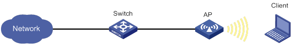
Procedure
1. Configure 802.1X and the local client:
# Configure the AP to perform EAP termination and use CHAP.
<AP> system-view
[AP] dot1x authentication-method chap
# Add a local network access user with username chap1 and password 123456 in plain text.
[AP] local-user chap1 class network
[AP-luser-network-chap1] password simple 123456
# Set the service type to lan-access.
[AP-luser-network-chap1] service-type lan-access
[AP-luser-network-chap1] quit
2. Configure AAA methods for the ISP domain:
# Create an ISP domain named local.
[AP] domain local
# Configure the ISP domain to use local authentication, local authorization, and local accounting for LAN clients.
[AP-isp-local] authentication lan-access local
[AP-isp-local] authorization lan-access local
[AP-isp-local] accounting lan-access local
[AP-isp-local] quit
3. Configure a service template:
# Create a service template named wlas_local_chap.
[AP] wlan service-template wlas_local_chap
# Set the authentication mode to 802.1X.
[AP-wlan-st-wlas_local_chap] client-security authentication-mode dot1x
# Specify ISP domain local for the service template.
[AP-wlan-st-wlas_local_chap] dot1x domain local
# Set the SSID to wlas_local_chap.
[AP-wlan-st-wlas_local_chap] ssid wlas_local_chap
# Enable the service template.
[AP-wlan-st-wlas_local_chap] service-template enable
[AP-wlan-st-wlas_local_chap] quit
4. Bind the service template to the AP radio.
[AP] interface wlan-radio 1/0/1
[AP-WLAN-Radio1/0/1] undo shutdown
[AP-WLAN-Radio1/0/1] service template wlas_local_chap
[AP-WLAN-Radio1/0/1] quit
Verifying the configuration
# Verify the 802.1X configuration.
[AP] display wlan service-template
[AP] display dot1x
# Display the client connection information after an 802.1X client passes authentication.
[AP] display dot1x connection
Example: Configuring 802.1X EAP-PEAP RADIUS authentication
Network configuration
As shown in Figure 32, configure the AP to perform 802.1X RADIUS authentication for the client by using EAP-PEAP.
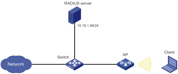
Procedure
1. Configure the AP:
a. Configure 802.1X and the RADIUS scheme:
# Configure the AP to use EAP relay to authenticate 802.1X clients.
<AP> system-view
[AP] dot1x authentication-method eap
# Create a RADIUS scheme.
[AP] radius scheme imcc
# Specify the primary authentication server and the primary accounting server.
[AP-radius-imcc] primary authentication 10.18.1.88 1812
[AP-radius-imcc] primary accounting 10.18.1.88 1813
# Set the authentication and accounting shared keys to 12345678 in plain text for secure RADIUS communication with the server.
[AP-radius-imcc] key authentication simple 12345678
[AP-radius-imcc] key accounting simple 12345678
# Exclude domain names from the usernames sent to the RADIUS server.
[AP-radius-imcc] user-name-format without-domain
[AP-radius-imcc] quit
b. Configure AAA methods for the ISP domain:
# Create an ISP domain named imc.
[AP] domain imc
# Configure the ISP domain to use RADIUS scheme imcc for authentication, authorization, and accounting of LAN clients.
[AP-isp-imc] authentication lan-access radius-scheme imcc
[AP-isp-imc] authorization lan-access radius-scheme imcc
[AP-isp-imc] accounting lan-access radius-scheme imcc
[AP-isp-imc] quit
c. Configure a service template:
# Create a service template named wlas_imc_peap.
[AP] wlan service-template wlas_imc_peap
# Set the authentication mode to 802.1X.
[AP-wlan-st-wlas_imc_peap] client-security authentication-mode dot1x
# Specify ISP domain imc for the service template.
[AP-wlan-st-wlas_imc_peap] dot1x domain imc
# Set the SSID to wlas_imc_peap.
[AP-wlan-st-wlas_imc_peap] ssid wlas_imc_peap
# Set the AKM mode to 802.1X.
[AP-wlan-st-wlas_imc_peap] akm mode dot1x
# Set the CCMP cipher suite.
[AP-wlan-st-wlas_imc_peap] cipher-suite ccmp
# Enable the RSN-IE in the beacon and probe responses.
[AP-wlan-st-wlas_imc_peap] security-ie rsn
# Enable the service template.
[AP-wlan-st-wlas_imc_peap] service-template enable
[AP-wlan-st-wlas_imc_peap] quit
d. Bind the service template to an AP radio.
[AP] interface wlan-radio 1/0/1
[AP-WLAN-Radio1/0/1] undo shutdown
[AP-WLAN-Radio1/0/1] service template wlas_local_chap
[AP-WLAN-Radio1/0/1] quit
2. Configure the RADIUS server:
In this example, the RADIUS server runs IMC PLAT 7.1 and IMC UAM 7.1, and the EAP-PEAP certificate has been installed.
# Add an access device:
a. Click the User tab.
b. From the navigation tree, select User Access Policy > Access Device Management > Access Device.
c. Click Add.
The Add Access Device page appears.
d. In the Access Configuration area, configure the following parameters, as shown in Figure 33:
- Enter 12345678 in the Shared Key and Confirm Shared Key fields.
- Use the default values for other parameters.
e. In the Device List area, click Select or Add Manually to add the device at 10.18.1.1 as an access device.
f. Click OK.
Figure 33 Adding an access device

# Add an access policy:
a. Click the User tab.
b. From the navigation tree, select User Access Policy > Access Policy.
c. Click Add.
d. On the Add Access Policy page, configure the following parameters, as shown in Figure 34:
- Enter dot1x in the Access Policy Name field.
- Select EAP for the Certificate Authentication field
- Select EAP-PEAP Auth from the Certificate Type list, and select MS-CHAPV2 Auth from the Certificate Sub-Type list.
The certificate sub-type on the IMC server must be the same as the identity authentication method configured on the client.
e. Click OK.
Figure 34 Adding an access policy
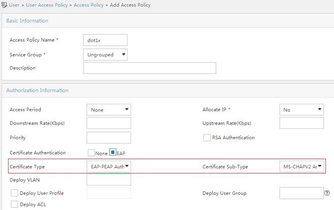
# Add an access service:
a. Click the User tab.
b. From the navigation tree, select User Access Policy > Access Service.
c. Click Add.
d. On the Add Access Service page, configure the following parameters, as shown in Figure 35:
- Enter dot1x in the Service Name field.
- Select dot1x from the Default Access Policy list.
e. Click OK.
Figure 35 Adding an access service
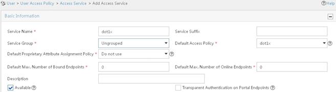
# Add an access user:
a. Click the User tab.
b. From the navigation tree, select Access User > All Access Users.
The access user list appears.
c. Click Add.
The Add Access User page appears.
d. In the Access Information area, configure the following parameters, as shown in Figure 36:
- Click Select or Add User to associate the user with IMC Platform user user.
- Enter user in the Account Name field.
- Enter dot1x in the Password and Confirm Password fields.
e. In the Access Service area, select dot1x from the list.
f. Click OK.
Figure 36 Adding an access user account
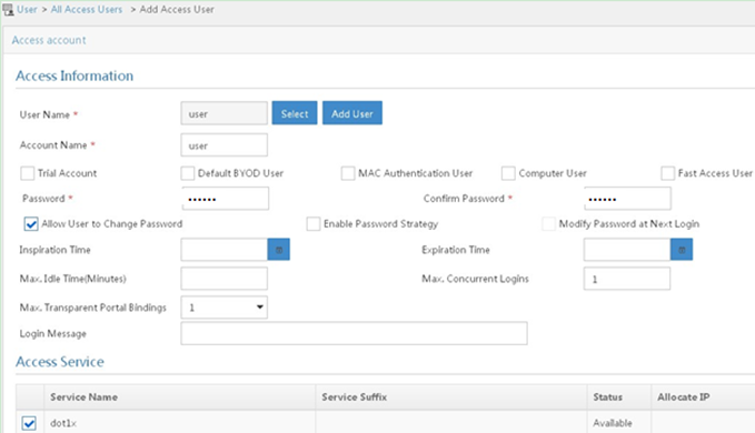
3. Configure the WLAN client:
The WLAN client has been installed with the EAP-PEAP certificate.
To configure the WLAN client, perform the following tasks (details not shown):
? Select PEAP for identity authentication.
? Disable the client from verifying the server certificate.
? Disable the client from automatically using the Windows login name and password.
Verifying the configuration
1. On the client, verify that you can use username user and password dot1x to access the network. (Details not shown.)
2. On the AP, perform the following tasks to verify that the user has passed authentication and come online:
# Display online 802.1X client information.
[AP] display dot1x connection
User MAC address : 0023-8933-2090
AP name : ap
Radio ID : 1
SSID : wlas_imc_peap
BSSID : 000f-e201-0003
User name : user
Authentication domain : imc
Authentication method : EAP
Initial VLAN : 1
Authorization VLAN : N/A
Authorization ACL number : N/A
Authorization user profile : N/A
Termination action : Default
Session timeout period : 6001 s
Online from : 2014/04/18 09:25:18
Online duration : 0h 1m 1s
Total connections: 1.
# Display WLAN client information.
[AP] display wlan client
Total number of clients : 1
MAC address Username AP name RID IP address IPv6 address VLAN
0023-8933-2090 user ap 1 10.18.1.100 1
Example: Configuring RADIUS-based MAC authentication
Network configuration
As shown in Figure 37, configure the AP to use the RADIUS server to perform MAC authentication for the client.
Procedure
Make sure the RADIUS server, switch, AP, and client can reach each other. (Details not shown.)
1. Configure the AP:
a. Configure the RADIUS scheme:
# Create a RADIUS scheme.
<AP> system-view
[AP] radius scheme imcc
# Specify the primary authentication server and the primary accounting server.
[AP-radius-imcc] primary authentication 10.18.1.88 1812
[AP-radius-imcc] primary accounting 10.18.1.88 1813
# Set the authentication and accounting shared keys to 12345678 in plain text for secure RADIUS communication with the server.
[AP-radius-imcc] key authentication simple 12345678
[AP-radius-imcc] key accounting simple 12345678
# Exclude domain names from the usernames sent to the RADIUS server.
[AP-radius-imcc] user-name-format without-domain
[AP-radius-imcc] quit
b. Configure AAA methods for the ISP domain:
# Create an ISP domain named imc.
[AP] domain imc
# Configure the ISP domain to use the RADIUS scheme imcc for authentication, authorization, and accounting of LAN clients.
[AP-isp-imc] authentication lan-access radius-scheme imcc
[AP-isp-imc] authorization lan-access radius-scheme imcc
[AP-isp-imc] accounting lan-access radius-scheme imcc
[AP-isp-imc] quit
c. Specify username 123 and password aaa_maca in plain text for the account shared by MAC authentication clients.
[AP] mac-authentication user-name-format fixed account 123 password simple aaa_maca
d. Configure a service template:
# Create a service template named maca_imc.
[AP] wlan service-template maca_imc
# Set the SSID to maca_imc.
[AP-wlan-st-maca_imc] ssid maca_imc
# Set the authentication mode to MAC authentication.
[AP-wlan-st-maca_imc] client-security authentication-mode mac
# Specify ISP domain imc for the service template.
[AP-wlan-st-maca_imc] mac-authentication domain imc
# Enable the service template.
[AP-wlan-st-maca_imc] service-template enable
[AP-wlan-st-maca_imc] quit
e. Bind the service template to an AP radio.
[AP] interface wlan-radio 1/0/1
[AP-WLAN-Radio1/0/1] undo shutdown
[AP-WLAN-Radio1/0/1] service template maca_imc
[AP-WLAN-Radio1/0/1] quit
2. Configure the RADIUS server:
In this example, the RADIUS server runs IMC PLAT 7.1 and IMC UAM 7.1.
# Add an access device:
a. Click the User tab.
b. From the navigation tree, select User Access Policy > Access Device Management > Access Device.
c. Click Add.
d. In the Access Configuration area, configure the following parameters, as shown in Figure 38:
- Enter 12345678 in the Shared Key and Confirm Shared Key fields.
- Use the default values for other parameters.
e. In the Device List area, click Select or Add Manually to add the device at 10.18.1.1 as an access device.
f. Click OK.
Figure 38 Adding an access device
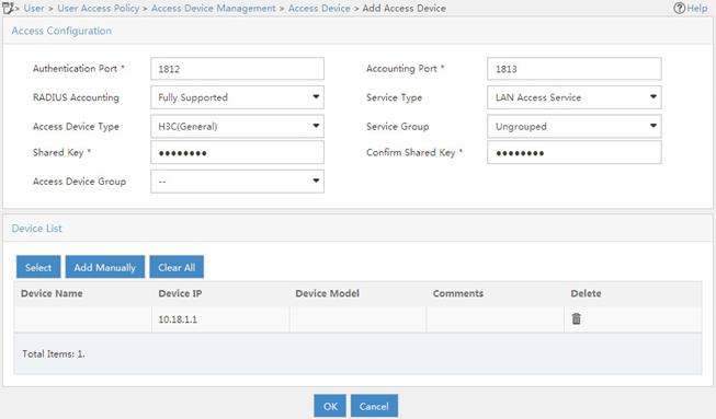
# Add an access policy:
a. Click the User tab.
b. From the navigation tree, select User Access Policy > Access Policy.
c. Click Add.
d. On the Add Access Policy page, configure the following parameters, as shown in Figure 39:
- Enter aaa_maca in the Access Policy Name field.
- Use the default values for other parameters.
e. Click OK.
Figure 39 Adding an access policy
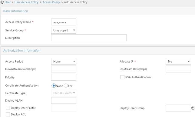
# Add an access service:
a. Click the User tab.
b. From the navigation tree, select User Access Policy > Access Service.
c. Click Add.
d. On the Add Access Service page, configure the following parameters, as shown in Figure 40:
- Enter aaa_maca in the Service Name field.
- Select aaa_maca from the Default Access Policy list.
e. Click OK.
Figure 40 Adding an access service
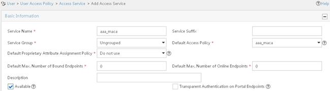
# Add an access user:
a. Click the User tab.
b. From the navigation tree, select Access User > All Access Users.
c. Click Add.
d. In the Access Information area, configure the following parameters, as shown in Figure 41:
- Click Select or Add User to associate the user with IMC Platform user 123.
- Enter 123 in the Account Name field.
- Enter aaa_maca in the Password and Confirm Password fields.
e. In the Access Service area, select aaa_maca from the list.
f. Click OK.
Figure 41 Adding an access user account
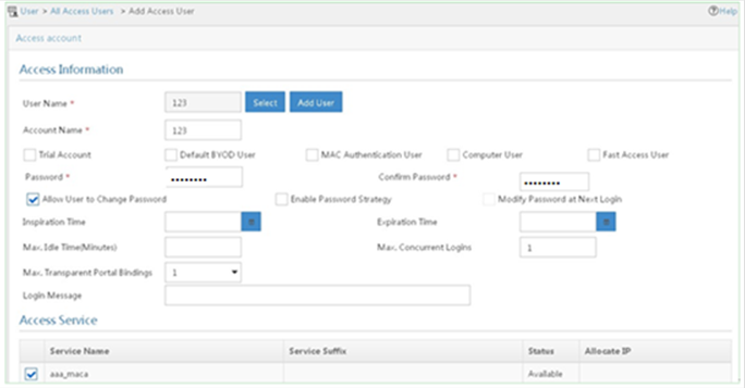
Verifying the configuration
1. On the client, verify that you can use username 123 and password aaa_maca to access the network. (Details not shown.)
2. On the AP, perform the following tasks to verify that the user has passed authentication and come online:
# Display online MAC authentication client information.
[AP] display mac-authentication connection
User MAC address : 0023-8933-2098
AP name : ap
Radio ID : 1
SSID : maca_imc
BSSID : 000f-e201-0001
User name : 123
Authentication domain : imc
Initial VLAN : 1
Authorization VLAN : N/A
Authorization ACL number : N/A
Authorization user profile : N/A
Termination action : Default
Session timeout period : 6001 s
Online from : 2014/04/17 17:21:12
Online duration : 0h 0m 30s
Total connections: 1.
# Display WLAN client information.
[AP] display wlan client
Total number of clients : 1
MAC address Username AP name RID IP address IPv6 address VLAN
0023-8933-2098 123 ap 1 10.18.1.100 1
Configuring WLAN QoS
The term "AP" in this document refers to MSR routers that support WLAN.
About WLAN QoS
An 802.11 network provides contention-based wireless access. To provide applications with QoS services, IEEE developed 802.11e for 802.11-based WLANs.
WLAN QoS features include WMM and SVP.
WMM protocol
About WMM
Wi-Fi Alliance defined the Wi-Fi Multimedia (WMM) standard to allow QoS provision devices of different vendors to interoperate. WMM enables a WLAN to provide QoS services, so that audio and video applications can have better performance in WLANs.
The Distributed Coordination Function (DCF) in 802.11 requires APs and clients to use the carrier sense multiple access with collision avoidance (CSMA/CA) access mechanism. APs or clients listen to the channel before they hold the channel for data transmission. When the specified idle duration of the channel times out, APs or clients randomly select a backoff slot within the contention window to perform backoff. The device that finishes backoff first gets the channel. With 802.11, all devices have the same idle duration and contention window. Therefore, they are equal when contending for a channel.
To provide QoS services, WMM divides data traffic into four ACs that have different priorities. Traffic in an AC with a high priority has a better chance to use the channel.
Terminology
· Enhanced distributed channel access—EDCA is a channel contention mechanism defined by WMM to preferentially transmit packets with high priority and allocate more bandwidth to such packets.
· Access category—WMM defines the following ACs: AC-VO for voice traffic, AC-VI for video traffic, AC-BE for best effort traffic, and AC-BK for background traffic. The priorities of the four ACs are in descending order.
· Connect Admission Control—CAC limits the number of clients that can use high-priority ACs (AC-VO and AC-VI) to make sure there is enough bandwidth for these clients.
· Unscheduled automatic power save delivery—U-APSD is a power saving method defined by WMM to save client power.
EDCA parameters
· Arbitration inter-frame spacing number—In 802.11-based WLAN, each client has the same idle duration (DIFS), but WMM defines an idle duration for each AC. The idle duration increases as the AIFSN increases.
· Exponent form of CWmin/Exponent form of CWmax—ECWmin/ECWmax determines the backoff slots, which increase as the two values increase.
· Transmission opportunity limit—TXOP limit specifies the maximum time that a client can hold the channel after a successful contention. A larger value represents a longer time. If the value is 0, a client can send only one packet each time it holds the channel.
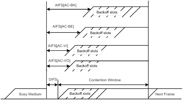
CAC admission policies
CAC requires a client to obtain permission from an AP before it can use a high-priority AC for transmission. This guarantees bandwidth for the clients that have gained access. CAC controls real time traffic (AC-VO and AC-VI traffic) but not common data traffic (AC-BE and AC-BK traffic).
If a client wants to use a high-priority AC (AC-VO or AC-VI), it must send a request to the AP. The AP returns a positive or negative response based on either of the following admission control policies:
· Channel usage-based admission policy—The AP calculates the total time that the existing high-priority AC queues occupy the channel per unit time, and then calculates the time that the requesting traffic will occupy the channel per unit time. If the sum of the two values is smaller than or equal to the maximum hold time of the channel, the client can use the requested AC queue. If it is not, the request is rejected.
· Client-based admission policy—If the number of clients using high-priority AC queues is smaller than the maximum number of high-priority AC clients, the request is accepted. If it is not, the request is rejected. During calculation, a client is counted as one client if it is using both the AC-VO and AC-VI queues.
If the request is rejected because of lack of media resources, the AP assigns AC-BE to the client. Clients that already use high-priority AC queues will not be affected.
When calculating media resources, the AP takes requests before CAC is enabled into account. Whether subsequent requests for high-priority AC queues will be accepted is greatly restricted by the resource usage.
U-APSD power-save mechanism
U-APSD enables clients in sleep mode to wake up and receive the specified number of packets only after receiving a trigger packet. U-APSD improves the 802.11 APSD power saving mechanism.
U-APSD is automatically enabled after you enable WMM.
ACK policy
WMM defines the following ACK policies:
· Normal ACK—The recipient acknowledges each received unicast packet.
· No ACK—The recipient does not acknowledge received packets during wireless packet exchange. This policy improves the transmission efficiency in an environment where communication quality is strong and interference is weak. If communication quality deteriorates, this policy might increase the packet loss rate. For A-MPDU packets sent by 802.11n clients, the No ACK policy does not take effect.
SVP
SpectraLink Voice Priority (SVP) is developed by SpectraLink to provide QoS services for voice traffic.
Protocols and standards
· 802.11e-2005, Amendment 8: Medium Access Control (MAC) Quality of Service Enhancements, IEEE Computer Society, 2005
· Wi-Fi, WMM Specification version 1.1, Wi-Fi Alliance, 2005
Feature and hardware compatibility
WLAN is supported only on the following routers:
· MSR810-W.
· MSR810-W-DB.
· MSR810-W-LM.
· MSR810-W-LM-HK.
· MSR810-W-LM-GL.
Configuring WMM
WMM tasks at a glance
|
Tasks at a glance |
|
(Required.) Enabling WMM |
|
(Optional.) Setting EDCA parameters |
|
(Optional.) Setting EDCA parameters of AC-BE or AC-BK queues for clients |
|
(Optional.) Setting EDCA parameters of AC-VI or AC-VO queues for clients |
|
(Optional.) Configuring a port to trust packet priority for priority mapping |
Enabling WMM
|
Step |
Command |
Remarks |
|
1. Enter system view. |
system-view |
N/A |
|
2. Enter radio interface view. |
interface wlan-radio interface-number |
N/A |
|
3. Enable WMM. |
wmm enable |
By default, WMM is enabled. The 802.11n protocol requires all 802.11n clients to support WLAN QoS. For 802.11n clients to communicate with the associated AP, enable WMM when the radio operates in 802.11an or 802.11gn mode. |
Setting EDCA parameters
|
Step |
Command |
Remarks |
|
1. Enter system view. |
system-view |
N/A |
|
2. Enter radio interface view. |
interface wlan-radio interface-number |
N/A |
|
3. Set EDCA parameters. |
edca radio { ac-be | ac-bk | ac-vi | ac-vo } { ack-policy { noack | normalack } | aifsn aifsn-value | ecw ecwmin ecwmin-value ecwmax ecwmax-value | txoplimit txoplimit-value } * |
The default values for EDCA parameters are shown in Table 15. |
Table 15 Default EDCA parameter values
|
AC |
AIFSN |
ECWmin |
ECWmax |
TXOP Limit |
|
AC-BK |
7 |
4 |
10 |
0 |
|
AC-BE |
3 |
4 |
6 |
0 |
|
AC-VI |
1 |
3 |
4 |
94 |
|
AC-VO |
1 |
2 |
3 |
47 |
Setting EDCA parameters of AC-BE or AC-BK queues for clients
|
Step |
Command |
Remarks |
|
1. Enter system view. |
system-view |
N/A |
|
2. Enter radio interface view. |
interface wlan-radio interface-number |
N/A |
|
3. Set EDCA parameters of AC-BE or AC-BK queues for clients. |
edca client { ac-be | ac-bk } { aifsn aifsn-value | ecw ecwmin ecwmin-value ecwmax ecwmax-value | txoplimit txoplimit-value } * |
The default values are shown in Table 16. |
Table 16 Default EDCA parameter values of AC-BE or AC-BK queues for clients
|
AC |
AIFSN |
ECWmin |
ECWmax |
TXOP Limit |
|
AC-BK |
7 |
4 |
10 |
0 |
|
AC-BE |
3 |
4 |
10 |
0 |
Setting EDCA parameters of AC-VI or AC-VO queues for clients
|
Step |
Command |
Remarks |
|
1. Enter system view. |
system-view |
N/A |
|
2. Enter radio interface view. |
interface wlan-radio interface-number |
N/A |
|
3. Set EDCA parameters of AC-VI or AC-VO queues for clients. |
edca client { ac-vi | ac-vo } { aifsn aifsn-value | cac { disable | enable } | ecw ecwmin ecwmin-value ecwmax ecwmax-value | txoplimit txoplimit-value } * |
The default values are shown in Table 17. |
|
4. (Optional.) Configure the CAC policy. |
cac policy { channelutilization [ channelutilization-value ] | client [ client-number ] } |
By default, the client-based admission policy is used, and the maximum number of admitted clients is 20. |
Table 17 Default EDCA parameter values of AC-VI or AC-VO queues for clients
|
AC |
AIFSN |
ECWmin |
ECWmax |
TXOP Limit |
|
AC-VI |
2 |
3 |
4 |
94 |
|
AC-VO |
2 |
2 |
3 |
47 |
Configuring a port to trust packet priority for priority mapping
About priority mapping
When the packet trust mode is disabled, an AP assigns the port priority to all packets for the service template.
Restrictions and guidelines
This feature takes effect only on uplink packets.
The port priority setting does not take effect if the trusted packet priority type is configured.
Procedure
|
Step |
Command |
Remarks |
|
1. Enter system view. |
system-view |
N/A |
|
2. Enter service template view. |
N/A |
|
|
3. Configure the trusted packet priority type. |
By default, the port priority is trusted. |
|
|
4. Set the port priority. |
By default, the port priority is 0. |
Configuring SVP mapping
About SVP mapping
This feature assigns packets that have the protocol ID 119 in the IP header to the AC-VI or AC-VO queue to provide SVP packets with the specified priority. SVP does not require random backoff for SVP packets. Therefore, you can set both ECWmin and ECWmax to 0 when there are only SVP packets in the AC-VI or AC-VO queue.
When SVP mapping is disabled, SVP packets are assigned to the AC-BE queue.
Restrictions and guidelines
SVP mapping takes effect only on non-WMM clients.
Procedure
|
Step |
Command |
Remarks |
|
1. Enter system view. |
system-view |
N/A |
|
2. Enter radio interface view. |
interface wlan-radio interface-number |
N/A |
|
3. Enable SVP mapping. |
svp map-ac { ac-vi | ac-vo } |
By default, SVP mapping is disabled. To disable SVP mapping, use the svp map-ac disable command. |
Display and maintenance commands for WMM
Execute display commands in any view and reset commands in user view.
|
Task |
Command |
|
Display WMM statistics for radios. |
display wlan wmm radio [ interface wlan-radio interface-number ] |
|
Display WMM statistics for clients. |
display wlan wmm client [ interface wlan-radio interface-number | mac-address mac-address ] |
|
Clear WMM statistics for radios. |
reset wlan wmm radio [ interface wlan-radio interface-number ] |
|
Clear WMM statistics for clients. |
reset wlan wmm client [ interface wlan-radio interface-number | mac-address mac-address ] |
WLAN QoS configuration examples
Example: Configuring basic WMM
Network configuration
As shown in Figure 43, enable WMM on the fat AP so that the fat AP and the client can prioritize the traffic.

Procedure
# Create a service template named market, set the SSID to market, and enable the service template.
<FAT AP> system-view
[FAT AP] wlan service-template market
[FAT AP-wlan-st-market] ssid market
[FAT AP-wlan-st-market] service-template enable
[FAT AP-wlan-st-market] quit
# Bind service template market to WLAN-Radio 0/1.
[FAT AP] interface wlan-radio 0/1
[FAT AP-WLAN-Radio0/1] undo shutdown
[FAT AP-WLAN-Radio0/1] service-template market
# Enable WMM.
[FAT AP-WLAN-Radio0/1] wmm enable
[FAT AP-WLAN-Radio0/1] quit
Verifying the configuration
# Display WMM statistics for radios.
[FAT AP] display wlan wmm radio
Radio : 1
Client EDCA updates : 0
QoS mode : WMM
WMM status : Enabled
Radio max AIFSN : 0 Radio max ECWmin : 0
Radio max TXOPLimit : 0 Radio max ECWmax : 0
CAC information
Clients accepted : 0
Voice : 0
Video : 0
Total request mediumtime (μs) : 0
Voice(μs) : 0
Video(μs) : 0
Calls rejected due to insufficient resources : 0
Calls rejected due to invalid parameters : 0
Calls rejected due to invalid medium time : 0
Calls rejected due to invalid delay bound : 0
Example: Configuring CAC
Network configuration
As shown in Figure 44, configure CAC to allow a maximum of 10 clients to use the AC-VO and AC-VI queues.
Procedure
# Create a service template named market, set the SSID to market, and enable the service template.
<FAT AP> system-view
[FAT AP] wlan service-template market
[FAT AP-wlan-st-market] ssid market
[FAT AP-wlan-st-market] service-template enable
[FAT AP-wlan-st-market] quit
# Bind service template market to WLAN-Radio 0/1.
[FAT AP] interface wlan-radio 0/1
[FAT AP-WLAN-Radio0/1] undo shutdown
[FAT AP-WLAN-Radio0/1] service-template market
# Enable WMM for AC-VO and AC-VI queues, and configure a CAC policy to limit the number of clients to 10.
[FAT AP-WLAN-Radio0/1] wmm enable
[FAT AP-WLAN-Radio0/1] edca client ac-vo cac enable
[FAT AP-WLAN-Radio0/1] edca client ac-vi cac enable
[FAT AP-WLAN-Radio0/1] cac policy client 10
Verifying the configuration
# Assume that a client requests to use a high-priority AC queue (AC-VO or AC-VI). Verify the following information:
· If the number of clients using high-priority AC queues is smaller than the maximum number of high-priority AC clients (10 in this example), the request is accepted.
· If the number of clients using high-priority AC queues is equal to the maximum number of high-priority AC clients (10 in this example), the request is rejected. The AP decreases the priority of packets from the client.
Example: Configuring SVP mapping
Network configuration
As shown in Figure 45, configure SVP mapping on the fat AP to assign SVP packets to the AC-VO queue. Set ECWmin and ECWmax to 0 for the AC-VO queue of the fat AP.
Procedure
# Create a service template named market, set the SSID to market, and enable the service template.
<FAT AP> system-view
[FAT AP] wlan service-template market
[FAT AP-wlan-st-market] ssid market
[FAT AP-wlan-st-market] service-template enable
[FAT AP-wlan-st-market] quit
# Bind service template market to WLAN-Radio 0/1.
[FAT AP] interface wlan-radio 0/1
[FAT AP-WLAN-Radio0/1] undo shutdown
[FAT AP-WLAN-Radio0/1] service-template market
# Enable WMM.
[FAT AP-WLAN-Radio0/1] wmm enable
# Assign SVP packets to the AC-VO queue, and set EDCA parameters of AC-VO queues for clients.
[FAT AP-WLAN-Radio0/1] svp map-ac ac-vo
[FAT AP-WLAN-Radio0/1] edca client ac-vo ecw ecwmin 0 ecwmax 0
Verifying the configuration
# Verify that the AC assigns SVP packets to the AC-VO queue if a non-WMM client comes online and sends SVP packets to the AC.
Example: Configuring traffic differentiation
Network configuration
As shown in Figure 46, configure priority mapping on the fat AP to add 802.11 packets from the client to the AC-VO queue.
Procedure
# Create a service template named market, set the SSID to market, and enable the service template.
<FAT AP> system-view
[FAT AP] wlan service-template market
[FAT AP-wlan-st-market] ssid market
[FAT AP-wlan-st-market] service-template enable
# Set the 802.11e priority of 802.11 packets from the client to 7.
[FAT AP-wlan-st-market] qos priority 7
[FAT AP-wlan-st-market] quit
# Bind service template market to WLAN-Radio 0/1.
[FAT AP] interface wlan-radio 0/1
[FAT AP-WLAN-Radio0/1] undo shutdown
[FAT AP-WLAN-Radio0/1] service-template market
# Enable WMM.
[FAT AP-WLAN-Radio0/1] wmm enable
[FAT AP-WLAN-Radio0/1] quit
Verifying the configuration
# Verify that packets from the client have been added to the AC-VO queue.
[FAT AP] display wlan statistics client
MAC address : 0015-005e-97cc
AP name : 7848-59f3-fd40
Radio ID : 1
SSID : market
BSSID : 7848-59f3-fd40
RSSI : 27
Sent frames:
Back ground : 0/0 (frames/bytes)
Best effort : 0/0 (frames/bytes)
Video : 0/0 (frames/bytes)
Voice : 14/1092 (frames/bytes)
Received frames:
Back ground : 0/0 (frames/bytes)
Best effort : 66/8177 (frames/bytes)
Video : 0/0 (frames/bytes)
Voice : 0/0 (frames/bytes)
Discarded frames:
Back ground : 0/0 (frames/bytes)
Best effort : 0/0 (frames/bytes)
Video : 0/0 (frames/bytes)
Voice : 0/0 (frames/bytes)
Configuring cloud connections
The term "AP" in this document refers to MSR routers that support WLAN.
About cloud connections
A cloud connection is a management tunnel established between a local device and the H3C Oasis server. It enables you to manage the local device from the H3C Oasis server without accessing the network where the device resides.
Multiple subconnections
After a local device establishes a connection with the H3C Oasis server, service modules on the local device can establish multiple subconnections with the microservices on the H3C Oasis server. These subconnections are independent from each other and provide separate communication channels for different services. This mechanism avoids interference among different services.
Cloud connection establishment
This section uses an AP and the H3C Oasis server as an example. The cloud connection is established as follows:
1. The AP sends an authentication request to the H3C Oasis server.
2. The H3C Oasis server sends an authentication success packet to the AP.
The AP passes the authentication only if the serial number of the AP has been added to the H3C Oasis server. If the authentication fails, the H3C Oasis server sends an authentication failure packet to the AP.
3. The AP sends a registration request to the H3C Oasis server.
4. The H3C Oasis server sends a registration response to the AP.
The registration response contains the uniform resource locator (URL) used to establish a cloud connection.
5. The AP uses the URL to send a handshake request (changing the protocol from HTTP to WebSocket) to the H3C Oasis server.
6. The H3C Oasis server sends a handshake response to the AP to finish establishing the cloud connection.
7. After the cloud connection is established, the AP automatically obtains the subconnection URLs and establishes subconnections with the H3C Oasis server based on the service needs.
Figure 47 Establishing a cloud connection
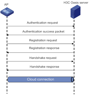
Feature and hardware compatibility
WLAN is supported only on the following routers:
· MSR810-W.
· MSR810-W-DB.
· MSR810-W-LM.
· MSR810-W-LM-HK.
· MSR810-W-LM-GL.
Configuring a cloud connection
Configuring the H3C Oasis server
For a successful cloud connection establishment, add the serial number of the device to be managed to the H3C Oasis server.
Configuring the local device
About configuring the local device
You can specify a domain name for the H3C Oasis server and log in to the server through the domain name on a remote PC to manage the local device.
If the local device does not receive a response from the H3C Oasis server within three keepalive intervals, the device sends a registration request to re-establish the cloud connection.
To prevent NAT entry aging, the local device sends ping packets to the H3C Oasis server periodically.
Restrictions and guidelines
Reduce the ping interval value if the network condition is poor or the NAT entry aging time is short.
Procedure
|
Step |
Command |
Remarks |
|
1. Enter system view. |
system-view |
N/A |
|
2. Configure the domain name of the H3C Oasis server. |
cloud-management server domain domain-name |
By default, the domain name of the H3C Oasis server is not configured. |
|
3. (Optional.) Set the keepalive interval. |
cloud-management keepalive interval |
By default, the keepalive interval is 180 seconds. |
|
4. (Optional.) Set the ping interval. |
cloud-management ping interval |
By default, the ping interval is 60 seconds. |
Display and maintenance commands for cloud connections
Execute display commands in any view.
|
Task |
Command |
|
Display cloud connection state information. |
display cloud-management state |
Cloud connection configuration examples
Example: Configuring a cloud connection
Network configuration
As shown in Figure 48, configure the AP to establish a cloud connection with the H3C Oasis server.
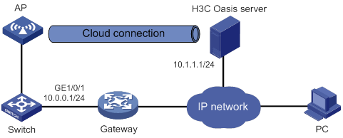
Procedure
1. Configure IP addresses for interfaces as shown in Figure 48, and configure a routing protocol to make sure the devices can reach each other. (Details not shown.)
2. Log in to the H3C Oasis server to add the serial number of the AP to the server. (Details not shown.)
3. Configure the domain name of the H3C Oasis server as lvzhouv3.h3c.com.
<AP> system-view
[AP] cloud-management server domain lvzhouv3.h3c.com
|
|
NOTE: The DNS service is provided by the ISP DNS server. |
Verifying the configuration
# Verify that the AP and the H3C Oasis server have established a cloud connection.
[AP] display cloud-management state
Cloud connection state : Established
Device state : Request_success
Cloud server address : 10.1.1.1
Cloud server domain name : lvzhouv3.h3c.com
Local port : 443
Connected at : Wed Jan 27 14:18:40 2016
Duration : 00d 00h 02m 01s
Configuring WLAN multicast optimization
The term "AP" in this document refers to MSR routers that support WLAN.
About WLAN multicast optimization
Multicast transmission in a wireless network has the following limitations:
· Great packet loss upon poor link quality—Multicast packets do not require acknowledgments and lost packets are not retransmitted.
· Low transmission efficiency—The device sends multicast packets at the lowest mandatory rate.
With these limitations, multicast transmission cannot meet the requirements for applications that are not sensitive to time delay but sensitive to data integrity. To address this issue, you can configure WLAN multicast optimization.
WLAN multicast optimization mechanism
WLAN multicast optimization enables an AP to convert multicast packets to unicast packets.
Figure 49 Data transmission with WLAN multicast optimization enabled
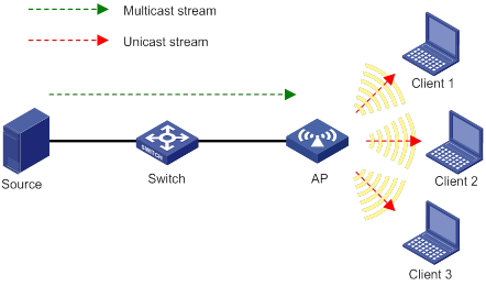
WLAN multicast optimization entries
WLAN multicast optimization uses multicast optimization entries to manage traffic forwarding. The multicast optimization entries use the clients' MAC addresses as indexes. A multicast optimization entry records information about multicast groups that clients join, multicast sources from which clients receive traffic, multicast group version, and multicast optimization mode.
After you enable WLAN multicast optimization, an AP creates or updates multicast optimization entries for a client according to the IGMP reports received from the client. If IGMPv3 or MLDv2 is used, the AP can also update the multicast sources allowed by the client. The AP removes a multicast optimization entry if it receives a leave message from the client or when the aging time for the entry expires. If you disable WLAN multicast optimization for the service template that an AP uses, the AP removes all multicast optimization entries.
When an AP receives a non-IGMP or non-MLD packet from a multicast source, the AP matches the multicast group address in the packet against the multicast optimization entries. If a match is found, the AP converts the multicast packet to unicast packets and sends the unicast packets to all clients in the multicast group. If no match is found, the AP discards the packet.
Feature and hardware compatibility
WLAN is supported only on the following routers:
· MSR810-W.
· MSR810-W-DB.
· MSR810-W-LM.
· MSR810-W-LM-HK.
· MSR810-W-LM-GL.
WLAN multicast optimization tasks at a glance
|
Tasks at a glance |
|
(Required.) Enabling WLAN multicast optimization |
|
(Optional.) Configuring a multicast optimization policy |
|
(Optional.) Setting rate limits for IGMP/MLD packets from clients |
|
(Optional.) Setting the limit for multicast optimization entries |
|
(Optional.) Setting the limit for multicast optimization entries per client |
|
(Optional.) Setting the aging time for multicast optimization entries |
Enabling WLAN multicast optimization
|
Step |
Command |
Remarks |
|
1. Enter system view. |
system-view |
N/A |
|
2. Enter service template view. |
wlan service-template service-template-name |
N/A |
|
3. Enable WLAN multicast optimization. |
·
Enable IPv4 WLAN multicast
optimization: ·
Enable IPv6 WLAN multicast optimization: |
By default, WLAN multicast optimization is disabled. |
Configuring a multicast optimization policy
About multicast optimization policies
A multicast optimization policy defines the maximum number of clients that WLAN multicast optimization supports and defines the following actions an AP takes when the limit is reached:
· Unicast forwarding—Sends unicast packets converted from a multicast packet to only n (n equal to the specified threshold) clients that are randomly selected.
· Multicast forwarding—Forwards the multicast packet to all clients.
· Packet dropping—Drops the multicast packet.
Procedure
|
Step |
Command |
Remarks |
|
1. Enter system view. |
system-view |
N/A |
|
2. Configure a multicast optimization policy. |
·
Configure an IPv4 WLAN multicast optimization
policy: ·
Configure an IPv6 WLAN multicast optimization
policy: |
By default, no multicast optimization policies exist and an AP performs multicast optimization for all clients. If you do not specify an action, an AP performs unicast forwarding. |
Setting rate limits for IGMP/MLD packets from clients
About rate limits for IGMP/MLD packets from clients
Perform this task to configure the maximum number of IGMP or MLD packets that an AP can receive from clients within the specified interval. The AP discards the excessive IGMP or MLD packets. For more information about IGMP or MLD, see IP Multicast Configuration Guide.
Procedure
|
Step |
Command |
Remarks |
|
1. Enter system view. |
system-view |
N/A |
|
2. Set the rate limit for IGMP or MLD packets from clients. |
·
Set the rate limit for IGMP packets from
clients: ·
Set the rate limit for MLD packets from
clients: |
By default, no rate limit is set for IGMP or MLD packets from clients. |
Setting the limit for multicast optimization entries
About the limit for multicast optimization entries
Each time a client joins a multicast group, the AP creates a multicast optimization entry for the multicast group. If multicast sources have been specified for a client when the client joins the multicast group, the AP also creates a multicast optimization entry for each multicast source. When a client leaves a multicast group or rejects a multicast source, the AP deletes the relevant multicast optimization entry for the client. These might consume system resources.
Perform this task to limit the number of multicast optimization entries to save system resources.
When the number of multicast optimization entries reaches the limit, the AP stops creating new entries until the number falls below the limit.
Procedure
|
Step |
Command |
Remarks |
|
1. Enter system view. |
system-view |
N/A |
|
2. Set the limit for multicast optimization entries. |
·
Set the limit for IPv4 multicast optimization
entries: ·
Set the limit for IPv6 multicast optimization
entries: |
By default, no limit is set for multicast optimization entries. |
Setting the limit for multicast optimization entries per client
About the limit for multicast optimization entries per client
Perform this task to limit the number of multicast optimization entries that an AP maintains for each client to prevent a client from occupying excessive system resources.
Procedure
|
Step |
Command |
Remarks |
|
1. Enter system view. |
system-view |
N/A |
|
2. Set the limit for multicast optimization entries per client. |
·
Set the limit for IPv4 multicast
optimization entries per client: ·
Set the limit for IPv6 multicast
optimization entries per client: |
By default, no limit is set for multicast optimization entries per client. |
Setting the aging time for multicast optimization entries
|
Step |
Command |
Remarks |
|
1. Enter system view. |
system-view |
N/A |
|
2. Set the aging time for multicast optimization entries. |
·
Set the aging time for IPv4 multicast
optimization entries: ·
Set the aging time for IPv6 multicast optimization
entries: |
By default, the aging time is 260 seconds for multicast optimization entries. |
Display and maintenance commands for WLAN multicast optimization
Execute display commands in any view and reset commands in user view.
|
Tasks |
Command |
|
Display IPv6 multicast optimization entry information. |
display wlan ipv6 multicast-optimization entry [ client mac-address [ group group-ip [ source source-ip ] ] ] |
|
Display IPv4 multicast optimization entry information. |
display wlan multicast-optimization entry [ client mac-address [ group group-ip [ source source-ip ] ] ] |
|
Clear IPv6 multicast optimization entries. |
reset wlan ipv6 multicast-optimization entry { all | client mac-address [ group group-ip [ source source-ip ] ] } |
|
Clear IPv6 multicast optimization entries for the specified multicast group. |
reset wlan ipv6 multicast-optimization entry group group-ip [ source source-ip ] |
|
Clear IPv4 multicast optimization entries. |
reset wlan multicast-optimization entry { all | client mac-address [ group group-ip [ source source-ip ] ] } |
|
Clear IPv4 multicast optimization entries for the specified multicast group. |
reset wlan multicast-optimization entry group group-ip [ source source-ip ] |
WLAN multicast optimization configuration examples
Example: Configuring basic WLAN multicast optimization
Network configuration
As shown in Figure 50, the switch acts as the DHCP server to assign IP addresses to the AP and clients. The AP provides wireless services to the clients through the SSID service. Configure WLAN multicast optimization to manage multicast packet forwarding.
Procedure
# Enable IGMP snooping both globally and for VLAN 1.
<AP> system-view
[AP] igmp-snooping
[AP-igmp-snooping] quit
[AP] vlan 1
[AP-vlan1] igmp-snooping enable
[AP-vlan1] quit
# Create service template 1, set its SSID to service, and enable WLAN multicast optimization for it.
[AP] wlan service-template 1
[AP-wlan-st-1] ssid service
[AP-wlan-st-1] service-template enable
[AP-wlan-st-1] multicast-optimization enable
[AP-wlan-st-1] quit
# Bind service template 1 to WLAN-Radio 1/0/1.
[AP] interface wlan-radio 1/0/1
[AP-WLAN-Radio1/0/1] undo shutdown
[AP-WLAN-Radio1/0/1] service-template 1
[AP-WLAN-Radio1/0/1] quit
# Set the aging time to 300 seconds for IPv4 multicast optimization entries.
[AP] wlan multicast-optimization aging-time 300
# Configure the AP to receive a maximum of 100 IGMP packets from clients every 60 seconds.
[AP] wlan multicast-optimization packet-rate-limit interval 60 threshold 100
# Set the limit for IPv4 multicast optimization entries to 100.
[AP] wlan multicast-optimization global entry-limit 100
# Set the limit for multicast optimization entries per client to 10.
[AP] wlan multicast-optimization client entry-limit 10
# Set the maximum number of clients that WLAN multicast optimization supports to 2, and configure the AP to drop multicast packets when the number of clients reaches the threshold.
[AP] wlan multicast-optimization entry client-limit 2 drop
Verifying the configuration
# Verify the following information after Client 1 and Client 2 join the multicast group with the address 230.1.1.1 and the multicast source address 1.1.1.1 has been specified. (Details not shown.):
· The AP has created multicast optimization entries for Client 1 and Client 2.
· Client 1 and Client 2 can receive traffic from the multicast source.
# Display information about multicast optimization entries after Client 3 joins the multicast group with the address 230.1.1.1 and the multicast source address 1.1.1.1 has been specified.
[AP] display wlan multicast-optimization entry
Total 3 clients reported
Client: 0001-0001-0001
Reported from AP 1 on radio 1
Total number of groups: 1
Group: 230.1.1.1
Version: IGMPv3
Mode: Include
Duration: 00h 00m 30s
Sources: 1
Source: 1.1.1.1
Duration: 00h 00m 30s
Client: 0001-0001-0002
Reported from AP 1 on radio 1
Total number of groups: 1
Group: 230.1.1.1
Version: IGMPv3
Mode: Include
Duration: 00h 00m 15s
Sources: 1
Source: 1.1.1.1
Duration: 00h 00m 15s
Client: 0001-0001-0003
Reported from AP 1 on radio 1
Total number of groups: 1
Group: 230.1.1.1
Version: IGMPv3
Mode: Include
Duration: 00h 00m 10s
Sources: 1
Source: 1.1.1.1
Duration: 00h 00m 10s
The output shows that the AP has created multicast optimization entries for Client 3.
# Verify that Client 1, Client 2, and Client 3 cannot receive traffic from the multicast source because the number of clients that WLAN multicast optimization supports exceeds the limit. (Details not shown.)
About band navigation,27
About cloud connections,123
About radio management,1
About WLAN access,31
About WLAN authentication,79
About WLAN multicast optimization,127
About WLAN QoS,113
About WLAN radio resource measurement,21
About WLAN security,46
Band navigation configuration examples,29
Band navigation tasks at a glance,27
Cloud connection configuration examples,125
Configuring 802.11n functions,14
Configuring a cloud connection,124
Configuring a multicast optimization policy,128
Configuring band navigation parameters,28
Configuring basic radio functions,7
Configuring client access control,39
Configuring global WLAN authentication parameters,88
Configuring load balancing for band navigation,28
Configuring security features,55
Configuring service-specific WLAN authentication parameters,92
Configuring SVP mapping,117
Configuring wireless client functions,37
Configuring wireless services,35
Configuring WMM,115
Disabling the AP from responding to broadcast probe requests,41
Display and maintenance commands for cloud connections,125
Display and maintenance commands for radio management,18
Display and maintenance commands for WLAN access,41
Display and maintenance commands for WLAN authentication settings,100
Display and maintenance commands for WLAN multicast optimization,131
Display and maintenance commands for WLAN radio resource measurement,24
Display and maintenance commands for WLAN security,60
Display and maintenance commands for WMM,118
Enabling band navigation globally,28
Enabling or disabling a radio interface,6
Enabling radio resource management,23
Enabling SNMP notifications for WLAN access,41
Enabling SNMP notifications for WLAN security,60
Enabling WLAN multicast optimization,128
Feature and hardware compatibility,128
Feature and hardware compatibility,124
Feature and hardware compatibility,5
Feature and hardware compatibility,115
Feature and hardware compatibility,22
Feature and hardware compatibility,87
Feature and hardware compatibility,54
Feature and hardware compatibility,27
Feature and hardware compatibility,34
Prerequisites for band navigation,28
Prerequisites for WLAN authentication,88
Pre-RSNA mechanism,46
Protocols and standards,54
Radio management configuration examples,19
Radio management tasks at a glance,5
Radio resource measurement configuration examples,24
Restrictions and guidelines: band navigation configuration,27
Setting rate limits for IGMP/MLD packets from clients,129
Setting the aging time for multicast optimization entries,130
Setting the limit for multicast optimization entries,129
Setting the limit for multicast optimization entries per client,130
Setting the match mode for client radio resource measurement capabilities,24
Setting the measurement duration and interval,23
Specifying a radio mode,6
Specifying a region code,40
Whitelist- and blacklist-based access control,33
WLAN access configuration examples,42
WLAN access tasks at a glance,34
WLAN authentication configuration examples,101
WLAN authentication tasks at a glance,87
WLAN multicast optimization configuration examples,131
WLAN multicast optimization tasks at a glance,128
WLAN QoS configuration examples,118
WLAN radio resource measurement tasks at a glance,22
WLAN security configuration examples,61
WLAN security tasks at a glance,54