- Table of Contents
- Related Documents
-
| Title | Size | Download |
|---|---|---|
| 01-Text | 3.54 MB |
Configuring analog voice interfaces
Feature and hardware compatibility
Command and hardware compatibility
Configuring call progress tones
Setting the electrical impedance
Configuring the packet loss compensation mode
Configuring an FXS interface to send LCFO signals
Configuring busy tone detection
Configuring ring detection parameters
Setting the electrical impedance
Configuring the packet loss compensation mode
Binding an FXS interface to an FXO interface
Configuring a start mode for E&M signaling
Configuring E&M non-signaling mode
Enabling E&M control signals pass-through
Configuring the output gain of SLIC chip
Configuring DTMF tone detection
Adjusting parameters for analog voice interfaces
Enabling the comfortable noise feature
Displaying and maintaining analog voice interfaces
Analog voice interface configuration examples
Two-dial configuration example for the FXO interface
FXO interface PLAR configuration example
E&M interface configuration example
E&M non-signaling mode configuration example
FXS&FXO 1:1 binding configuration example
Configuring digital voice interfaces
Feature and hardware compatibility
Command and hardware compatibility
E1 and T1 interface configuration task list
BSV interface configuration task list
Configuring basic parameters for an E1 interface
Configuring a TDM clock source
Configuring basic parameters for a T1 interface
Configuring a TDM clock source
Configuring a logical digital voice interface
Configuring basic R2 signaling parameters
Configuring R2 digital line signaling
Configuring R2 interregister signaling
Binding a digital voice interface to a POTS entity
Enabling the router to treat DISCONNECT messages with PI 8 as standard DISCONNECT messages
Adjusting parameters for digital voice interfaces
Enabling the comfortable noise feature
Displaying and maintaining digital voice interfaces
Digital voice interface configuration examples
R2 signaling configuration example
E1 DSS1 signaling configuration example
BSV DSS1 signaling configuration example
Feature and hardware compatibility
Creating a POTS entity and configuring basic parameters
Configuring codecs for a POTS entity
Configuring a POTS entity to register with the registrar
Configuring DTMF for a POTS entity
Setting a DSCP value for a POTS entity
Configuring playout delay for a POTS entity
Enabling VAD for a POTS entity
Configuring the POTS entity to play ringback tones
Configuring options related to dial program
Creating a VoIP entity and configuring basic parameters
Configuring codecs for a VoIP entity
Configuring DTMF for a VoIP entity
Enabling VAD for a VoIP entity
Setting a DSCP value for a VoIP entity
Configuring playout delay for a VoIP entity
Configuring the VoIP entity to play ringback tones
Configuring options related to dial program
Creating an IVR entity and configuring basic parameters
Configuring codecs for an IVR entity
Configuring an IVR entity to register with the registrar
Configuring DTMF for an IVR entity
Setting a DSCP value for an IVR entity
Enabling VAD for an IVR entity
Configuring options related to dial program
Setting the RTP timeout period
Setting the maximum duration of DSP-buffered data
Displaying and maintaining voice entities
Feature and hardware compatibility
Configuring caller group control
Configuring a subscriber group
Configuring a caller group on a voice entity
Enabling private line auto ring-down
Configuring a number match mode
Configuring the maximum number of calls allowed by a voice entity
Configuring number substitution
Number substitution on the calling router
Number substitution on the called router
Configuring global number substitution
Configuring number substitution for a voice entity
Configuring number substitution for a voice interface
Configuring a priority for a voice entity
Configuring the voice entity selection order
Configuring a number sending mode
Dial program configuration examples
Configuring number substitution
Configuring caller group control
Configuring the maximum number of calls
Transport protocols supported by SIP
Feature and hardware compatibility
Configuring SIP UA registration
Enabling a POTS entity to register with the registrar
Configuring the call destination address for a VoIP entity
Configuring the call destination IP address for a VoIP entity
Configuring a VoIP entity to obtain the call destination address from a proxy server
Configuring the destination domain name and port number for a VoIP entity
Configuring out-of-dialog keepalive for a VoIP entity
Configuring INVITE retransmission
Configuring extended SIP functions
Configuring source interface binding for outgoing SIP messages or media packets
Configuring out-of-band DTMF signaling
Configuring SIP session refresh
Configuring in-dialog keepalive
Configuring PSTN cause-to-SIP status mappings
Setting the P-Asserted-Identity or P-Preferred-Identity header field
Configuring reliable provisional responses
Configuring transport protocols for SIP calls
Configuring UDP or TCP for outgoing SIP calls
Enabling the UDP or TCP listening port
Setting the aging time for TCP connections
Configuring TLS as the transport protocol
Configuring SRTP for SIP calls
Specifying a global URL scheme for outgoing SIP calls
Specifying a URL scheme for outgoing SIP calls on a VoIP entity
Configuring QSIG tunneling over SIP-T
Displaying and maintaining SIP
Configuring direct SIP calling
Configuring SIP calling through a SIP server
Configuring SIP calling through DNS
Configuring SIP to use TCP as the transport protocol
Configuring SIP to use TLS as the transport protocol
Configuring out-of-band DTMF signaling
Feature and hardware compatibility
SIP trunk configuration task list
Configuring a SIP trunk account
Enabling codec transparent transmission
Displaying and maintaining SIP trunk
SIP trunk configuration examples
Feature and hardware compatibility
Call services configuration task list
Configuring the call hold mode
Displaying and maintaining MWI
Call services configuration examples
Call waiting configuration example
Call forwarding configuration example
Call transfer configuration example
Call backup configuration example
Three-party conference configuration example
Feature and hardware compatibility
Configuring the standard T.38 protocol
Configuring an NSF code for nonstandard capabilities negotiation
Configuring the maximum fax rate for rate training
Configuring a rate training mode
Adjusting the transmit energy level
Configuring modem pass-through
Configuring modem pass-through
Call services supported by SRST
Feature and hardware compatibility
Configuring SIP registration parameters
Configuring the keepalive feature
Configuring call services supported by SRST
Displaying and maintaining SRST
SIP registrar configuration example
Keepalive feature configuration example
PSTN backup configuration example
Basic call services configuration example
Call pickup configuration example
Call forwarding configuration example
Call blocking configuration example
FACs configuration example (on a gateway)
FACs for the call forwarding service configuration example (on a voice server)
FACs for the call pickup service configuration example (on a voice server)
Feature and hardware compatibility
Customizable IVR configuration task list
Specifying an ID for a media file
Configuring global handling policies
Displaying and maintaining customizable IVR
Customizable IVR configuration examples
Call node configuration example 1: dial terminator match, normal secondary call
Call node configuration example 2: number length match, normal secondary call
Call node configuration example 3: number match, normal secondary call
Call node configuration example 4: extension secondary call
Jump node configuration example
Service node configuration example 1
Service node configuration example 2
Comprehensive IVR node configuration example
Node depth exceeds eight levels
Configuring analog voice interfaces
Overview
Analog voice interfaces include FXS, FXO, and E&M interfaces.
FXS interface
A Foreign Exchange Station (FXS) interface connects to a standard telephone, fax machine, or a Private Branch Exchange (PBX) through an RJ-11 connector and a telephone cable. It provides ring, voltage, and dial tone based on level changes on the Tip/Ring line. An FXS interface can only connect to an FXO interface.
FXO interface
A foreign exchange office (FXO) interface connects to a PBX through an RJ-11 connector and a telephone cable. It provides ring, voltage, and dial tone based on level changes on the Tip/Ring line. An FXO interface can only connect to an FXS interface.
E&M interface
An ear & mouth or rEceive & transMit (E&M) interface is a common trunk line that connects to a PBX through an RJ-48 connector. The E&M interface supports E&M signaling. The E signaling receives signals from the peer, and the M signaling sends signals to the peer. An E&M interface can only connect to an E&M interface.
Compatibility information
Feature and hardware compatibility
|
Hardware |
Analog voice interface compatibility |
|
MSR810/810-W/810-W-DB/810-LM/810-W-LM/810-10-PoE/810-LM-HK/810-W-LM-HK/810-LMS/810-LUS |
No |
|
MSR2600-6-X1/2600-10-X1 |
Yes |
|
MSR 2630 |
Yes |
|
MSR3600-28/3600-51 |
Yes |
|
MSR3600-28-SI/3600-51-SI |
No |
|
MSR3610-X1/3610-X1-DP/3610-X1-DC/3610-X1-DP-DC |
Yes |
|
MSR 3610/3620/3620-DP/3640/3660 |
Yes |
|
MSR5620/5660/5680 |
Yes (not supported on the router installed with an SPU600-X1 card.) |
|
Hardware |
Analog voice interface compatibility |
|
MSR810-LM-GL |
No |
|
MSR810-W-LM-GL |
No |
|
MSR830-6EI-GL |
No |
|
MSR830-10EI-GL |
No |
|
MSR830-6HI-GL |
No |
|
MSR830-10HI-GL |
No |
|
MSR2600-6-X1-GL |
Yes |
|
MSR3600-28-SI-GL |
No |
Command and hardware compatibility
Commands and descriptions for centralized devices apply to the following routers:
· MSR810/810-W/810-W-DB/810-LM/810-W-LM/810-10-PoE/810-LM-HK/810-W-LM-HK/810-LMS/810-LUS.
· MSR2600-6-X1/2600-10-X1.
· MSR 2630.
· MSR3600-28/3600-51.
· MSR3600-28-SI/3600-51-SI.
· MSR3610-X1/3610-X1-DP/3610-X1-DC/3610-X1-DP-DC.
· MSR 3610/3620/3620-DP/3640/3660.
· MSR810-LM-GL/810-W-LM-GL/830-6EI-GL/830-10EI-GL/830-6HI-GL/830-10HI-GL/2600-6-X1-GL/3600-28-SI-GL.
Commands and descriptions for distributed devices apply to the following routers:
· MSR5620.
· MSR 5660.
· MSR 5680.
Configuration task list
|
Tasks at a glance |
|
(Optional.) Configuring basic settings |
|
(Optional.) Configuring call progress tones |
|
(Optional.) Configuring an FXS interface: · Setting the electrical impedance |
|
(Optional.) Configuring an FXO interface: · Configuring busy tone detection · Configuring an on-hook delay · Configuring the off-hook mode · Configuring ring detection parameters · Setting the electrical impedance |
|
(Optional.) Binding an FXS interface to an FXO interface |
|
(Optional.) Configuring an E&M interface: · Configuring a start mode for E&M signaling |
|
(Optional.) Configuring DTMF signaling: |
|
(Optional.) Adjusting parameters for analog voice interfaces: · Enabling the comfortable noise feature |
Configuring basic settings
|
Step |
Command |
Remarks |
|
1. Enter system view. |
system-view |
N/A |
|
2. Enter analog voice interface view. |
subscriber-line line-number |
N/A |
|
3. Configure a description for the analog voice interface. |
description text |
By default, the description of an analog voice interface is interface name Interface. |
|
4. Restore the default settings for the analog voice interface. |
default |
N/A |
|
5. Bring up the analog voice interface. |
undo shutdown |
By default, an analog voice interface is up. |
Configuring call progress tones
Perform this task to configure call progress tones for all voice interfaces on the device.
To configure call progress tones:
|
Step |
Command |
Remarks |
|
1. Enter system view. |
system-view |
N/A |
|
2. Enter voice view. |
voice-setup |
N/A |
|
3. Configure call progress tones. |
·
Specify a country: ·
Customize call progress tone parameters: |
By default, the call progress tones of China are used. |
|
4. Configure the amplitude value for call progress tones. |
cptone tone-type { all | busy-tone | congestion-tone | dial-tone | ringback-tone | special-dial-tone | waiting-tone } amplitude value |
Defaults are: · 1000 for busy tone and congestion tone. · 400 for dial tone and special dial tone. · 600 for ringback tone and waiting tone. |
Configuring an FXS interface
This section covers the procedures for configuring an FXS interface.
Configuring CID
Caller identification (CID) enables called terminals to display the calling information, including the calling number, calling name, date, and time.
CID supports the following data formats:
· Single-data-message format—Contains date and time when the voice call occurs (MM DD hh:mm), and calling number.
· Multiple-data-message format—Contains date and time when the voice call occurs (MM DD hh:mm), calling number, and calling name.
The called telephone displays the calling number differently as follows:
· The called telephone displays the calling number if the terminating device is enabled with CID and can obtain the calling number.
· The called telephone displays the character "O" if the terminating device is enabled with CID but fails to obtain the calling number (for example, the originating device does not send the calling number).
· The called telephone displays the character "P" if CID is disabled on the terminating device.
The FXS interface sends the CID to the called telephone through frequency shift keying (FSK) modulation between the first and second rings. For the CID to appear on the called telephone, the called user should pick up the handset after the second ring.
The CID feature requires configurations on both FXS and FXO interfaces. For configuration on the FXO interface, see "Configuring CID."
Configuration guidelines
· The PBX and called telephones must support CID.
· To ensure correct call time, make sure the router system time transmitted in data-message format stays synchronous with the local standard time.
· For the CID feature to operate correctly, keep the cid send command enabled.
Configuration procedure
|
Step |
Command |
Remarks |
|
1. Enter system view. |
system-view |
N/A |
|
2. Enter FXS interface view. |
subscriber-line line-number |
N/A |
|
3. (Optional.) Configure the calling name for the FXS interface. |
calling-name text |
By default, no calling name exists. The calling name can be sent only in the multiple-data-message format. |
|
4. Enable the FXS interface to send CID to the remote end. |
cid send |
Optional. By default, this feature is enabled. Use this command on the originating device. |
|
5. Configure the standard mode for sending CID. |
cid standard-type { bellcore | brazil } |
By default, the bellcore mode is used. This command is for use on the terminating device, which encapsulates the CID by using the configured standard mode and sends it to the called telephone. The message format configured by using the cid type command takes effect only when the bellcore mode is used. |
|
6. Configure the data message format. |
cid type { complex | simple } |
The default is complex. Use this command on the terminating device. When the originating device supports only one message format, you must use that message format on the terminating device. |
|
7. Enable CID on the FXS interface. |
cid display |
By default, CID is enabled on an FXS interface. Use this command on the terminating device. |
Setting the electrical impedance
The electrical impedance setting must be subject to country specifications. Each country corresponds to an impedance value. You specify an impedance value while specifying a country.
To set the electrical impedance:
|
Step |
Command |
Remarks |
|
1. Enter system view. |
system-view |
N/A |
|
2. Enter FXS interface view. |
subscriber-line line-number |
N/A |
|
3. Set the electrical impedance. |
impedance { country-name | r550 | r600 | r650 | r700 | r750 | r800 | r850 | r900 | r950 } |
The default is the electrical impedance of China. You must configure the same electrical impedance value on the originating and terminating devices. |
Configuring the packet loss compensation mode
You can configure the packet loss compensation mode to alleviate the impact of packet loss on voice quality.
· For discrete packet loss, you can use the general compensation mode to reconstruct lost packets.
· For continuous packet loss, you can use the voice gateway-specific compensation mode to compensate for lost packets.
To configure the packet loss compensation mode:
|
Step |
Command |
Remarks |
|
1. Enter system view. |
system-view |
N/A |
|
2. Enter FXS interface view. |
subscriber-line line-number |
N/A |
|
3. Configure the packet loss compensation mode for the FXS interface. |
plc-mode { general | specific } |
By default, the specific algorithm provided by the voice gateway is used for an FXS interface. |
Configuring an FXS interface to send LCFO signals
You can configure an FXS interface to send a loop current feed open (LCFO) signal to indicate a disconnection to the peer. This feature is used mainly in North America.
To configure an FXS interface to send LCFO signals:
|
Step |
Command |
Remarks |
|
1. Enter system view. |
system-view |
N/A |
|
2. Enter FXS interface view. |
subscriber-line line-number |
N/A |
|
3. Configure the FXS interface to send LCFO signals. |
disconnect lcfo |
By default, no LCFO signal is sent (a busy tone is played to the peer end). |
|
4. Set the duration of the LCFO signal. |
timer disconnect-pulse value |
The default is 750 milliseconds. |
Configuring an FXO interface
This section covers the procedures for configuring an FXO interface.
Configuring CID
The CID feature must be configured on both the FXS and FXO interfaces. For information about configuring this feature on the FXS interface, see "Configuring CID."
For the CID feature to work correctly, enable both CID receiving and CID sending.
Enabling CID receiving for an FXO interface
The FXO interface receives the CID. By default, it detects the CID from the PBX between the first and second rings.
To enable CID receiving:
|
Step |
Command |
Remarks |
|
1. Enter system view. |
system-view |
N/A |
|
2. Enter FXO interface view. |
subscriber-line line-number |
N/A |
|
3. Set the time for CID detection and the number of rings the FXO interface receives before going off-hook. |
cid ring { 0 | 1 | 2 } [ times ] |
By default, an FXO interface performs CID detection between the first and second rings, and it goes off-hook as soon as finishing the detection (cid ring 1 0). |
|
4. Enable CID receiving for the FXO interface. |
cid receive |
By default, this feature is enabled. |
Enabling CID sending for an FXO interface
|
Step |
Command |
Remarks |
|
1. Enter system view. |
system-view |
N/A |
|
2. Enter FXO interface view. |
subscriber-line line-number |
N/A |
|
3. Enable CID sending for the FXO interface. |
cid send |
By default, this feature is enabled. |
Configuring busy tone detection
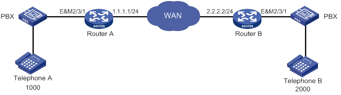
PBX switches might use different busy tone standards. If a user on the PBX side hangs up, the router knows the on-hook operation by detecting a busy tone. If the router cannot correctly identify the played busy tones, the FXO interface on the router will remain seized or goes on-hook prematurely.
As shown in Figure 1, Telephone A establishes a call to Telephone B, and then Telephone A goes on-hook. The PBX plays busy tones to Router A after detecting the on-hook condition of Telephone A. If Router A cannot detect the played busy tones, the FXO interface on Router A will remain seized. To solve this problem, you can configure busy tone detection for the FXO interface.

You can configure busy tone detection by customizing busy tone parameters or configuring automatic busy tone detection. If the tone that the router receives from the PBX matches the busy tone parameters, the router considers the tone as a busy tone and renders the FXO interface on-hook.
Configuring a busy tone standard
Two busy tone standards are available: European and North American. After you specify a standard, the device uses a set of parameters compliant with that standard for busy tone detection. If the actual busy tone data do not completely match the set of parameters, the device can use customized busy tone parameters or automatic busy tone detection to accurately detect busy tones.
To configure a busy tone standard:
|
Step |
Command |
Remarks |
|
1. Enter system view. |
system-view |
N/A |
|
2. Enter voice view. |
voice-setup |
N/A |
|
3. Specify a busy tone standard. |
area { europe | north-america } |
By default, the European standard is used. |
Customizing busy tone parameters
|
Step |
Command |
Remarks |
|
1. Enter system view. |
system-view |
N/A |
|
2. Enter voice view. |
voice-setup |
N/A |
|
3. Customize busy tone parameters. |
busytone-detect custom area-number index argu f1 f2 p1 p2 p3 p4 p5 p6 p7 |
By default, no custom busy tone parameters exist. The standard of busy tones depends on the area command. |
|
4. Enable using customized busy tone parameters. |
area custom |
By default, the European standard is used. This command takes effect on all FXO interfaces on the device. The customized busy tone parameters take effect only after you configure this command. |
Configuring automatic busy tone detection
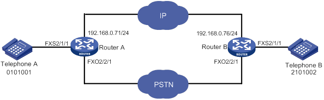
Figure 2 Automatic busy tone detection
As shown in Figure 2, the procedure for automatic busy tone detection is as follows:
1. Place a call from Telephone A to Telephone B.
2. Hang up Telephone A first.
The PBX plays a busy tone to Router A after detecting the on-hook condition.
3. Execute the busytone-detect auto command on Router A to detect busy tones.
As a best practice, execute this command two seconds after Telephone A goes on-hook to make sure the FXO interface can capture the busy tones sent by the PBX.
The console prompts that busy tone detection is in progress and prompts detection success when the detection is complete.
4. Check whether the detected busy tone parameters are valid by repeating steps 1 and 2.
After Telephone A goes on-hook, the PBX plays a busy tone to Router A. If Router A detects the busy tone, it shuts down the FXO interface.
To configure automatic busy tone detection:
|
Step |
Command |
Remarks |
|
1. Enter system view. |
system-view |
N/A |
|
2. Enter voice view. |
voice-setup |
N/A |
|
3. Configure automatic busy tone detection. |
busytone-detect auto index line-number |
N/A |
|
4. Return to system view. |
quit |
N/A |
|
5. Enter FXO interface view. |
subscriber-line line-number |
N/A |
|
6. Set the number of busy tone detection periods. |
busytone-detect period value |
The default is 2. Test multiple values to select the value that can ensure normal on-hook. |
Configuring busy tone sending
If the PBX does not play busy tones, configure the FXO interface to send busy tones.
To configure busy tone sending:
|
Step |
Command |
Remarks |
|
1. Enter system view. |
system-view |
N/A |
|
2. Enter FXO interface view. |
subscriber-line line-number |
N/A |
|
3. Enable busy tone sending. |
send-busytone enable |
By default, this feature is disabled. |
|
4. Set the busy tone duration. |
send-busytone time seconds |
The default is 3 seconds. |
Configuring silence detection-based automatic on-hook
|
|
CAUTION: Improper configuration of this feature can lead to false on-hook. To avoid false on-hook, configure multiple sets of parameters and select the set of parameters that will quickly release the FXO interface. |
If the device fails to detect busy tones or the PBX does not play busy tones, you can configure this feature to implement automatic on-hook.
When the duration of silence (whose volume is smaller than the configured threshold) exceeds the configured silence duration, the FXO interface automatically disconnects the call.
To configure silence detection-based automatic on-hook:
|
Step |
Command |
Remarks |
|
1. Enter system view. |
system-view |
N/A |
|
2. Enter FXO interface view. |
subscriber-line line-number |
N/A |
|
3. Configure silence detection-based automatic on-hook. |
silence-detect threshold threshold time time-length |
By default, the silence threshold is 20, and the silence duration is 7200 seconds (2 hours). |
Configuring forced on-hook
In some countries, PBXs do not play busy tones, or the busy tones only last for a short period of time. When noise is present on a link, even the silence detection-based automatic on-hook feature (configured with silence-detect threshold) cannot detect the busy tones and fails to release a call after on-hook. To solve this problem, configure the forced on-hook feature. Forced on-hook disconnects a call when the specified time expires, even if the call is ongoing.
To configure forced on-hook:
|
Step |
Command |
Remarks |
|
1. Enter system view. |
system-view |
N/A |
|
2. Enter FXO interface view. |
subscriber-line line-number |
N/A |
|
3. Configure forced on-hook. |
hookoff-time time |
By default, forced on-hook is disabled. If you configure this command on an FXO interface of a card, the configuration takes effect on all FXO subscriber lines of the card. |
Configuring an on-hook delay
An FXO interface goes on-hook when detecting a busy tone. This will cause the user of an IP phone connected to the FXO interface to mistake the on-hook as a line problem because the user cannot hear the busy tones.
To solve this problem, you can configure a delay time. During the delay time, the FXO interface continues sending the busy tones to the IP phone.
To configure an on-hook delay:
|
Step |
Command |
Remarks |
|
1. Enter system view. |
system-view |
N/A |
|
2. Enter FXO interface view. |
subscriber-line line-number |
N/A |
|
3. Set the delay time from when the FXO interface detects a busy tone to when the interface goes on-hook. |
The delay time is 0 seconds (the FXO interface goes on-hook immediately after detecting a busy tone). |
Configuring the off-hook mode
The FXO interface supports the following off-hook modes:
· Immediate mode—Upon receiving a call, the FXO interface goes off-hook and sends a dial tone to the calling party. Then, the calling party dials the destination number.
· Delay mode—Upon receiving a call, the FXO interface places a call to the specified private line number. When the called party picks up the phone, the FXO goes off-hook. This mode needs to work with the private line auto ring-down (PLAR) feature. For more information about PLAR, see "Configuring dial programs."
To configure the off-hook mode:
|
Step |
Command |
Remarks |
|
1. Enter system view. |
system-view |
N/A |
|
2. Enter FXO interface view. |
subscriber-line line-number |
N/A |
|
3. Configure the off-hook mode. |
hookoff-mode { delay | immediate } |
By default, the immediate mode is used. |
Configuring ring detection parameters
PBXs from different vendors use different types of ring signals. By setting ring detection parameters, you can enable the FXO interface to detect ring signals of different frequencies and waveforms.
To configure ring detection parameters:
|
Step |
Command |
Remarks |
|
1. Enter system view. |
system-view |
N/A |
|
2. Enter FXO interface view. |
subscriber-line line-number |
N/A |
|
3. Set the debounce time for ring detection on the FXO interface. |
ring-detect debounce value |
The default is 10 milliseconds. This command is supported only on the SIC-1FXO, SIC-2FXO, and HMIM-4FXO interface modules. Do not set the debounce time during a conversation. As a best practice, set the debounce time to be no less than 8 milliseconds to prevent interference from causing false ring tone recognition. If you configure this command on an FXO interface, the configuration takes effect on all FXO subscriber lines on the same module as that interface. |
|
4. Set the frequency value for ring detection. |
ring-detect frequency value |
The default is 40 Hz. This command is supported only on the SIC-2FXS1FXO, HMIM-8FXS8FXO, and DSIC-4FXS1FXO interface modules. |
Setting the electrical impedance
The electrical impedance setting must be subject to country specifications. Each country corresponds to an impedance value. You specify an impedance value while specifying a country.
To set the electrical impedance:
|
Step |
Command |
Remarks |
|
1. Enter system view. |
system-view |
N/A |
|
2. Enter FXO interface view. |
subscriber-line line-number |
N/A |
|
3. Set the electrical impedance of a country. |
impedance { country-name | r550 | r600 | r650 | r700 | r750 | r800 | r850 | r900 | r950 } |
The default is the electrical impedance of China. You must configure the same electrical impedance value on the originating and terminating devices. |
Configuring the packet loss compensation mode
You can configure the packet loss compensation mode to alleviate the impact on voice quality.
· For discrete packet loss, you can use the general compensation mode to reconstruct lost packets.
· For continuous packet loss, you can use the voice gateway-specific compensation mode to reconstruct lost packets.
To configure the packet loss compensation mode:
|
Step |
Command |
Remarks |
|
1. Enter system view. |
system-view |
N/A |
|
2. Enter FXO interface view. |
subscriber-line line-number |
N/A |
|
3. Specify a packet loss compensation mode for the FXO interface. |
plc-mode { general | specific } |
By default, the voice gateway-specific compensation mode is used for an FXO interface. |
Enabling online monitoring
This feature monitors the physical states of all FXO interfaces on the device.
If this feature is disabled, the device does not detect the physical states of FXO interfaces. All FXO interfaces are always shown in up state.
To enable online monitoring:
|
Step |
Command |
Remarks |
|
1. Enter system view. |
system-view |
N/A |
|
2. Enter voice view. |
voice-setup |
N/A |
|
3. Enable online monitoring. |
monitor enable |
By default, online monitoring is enabled. |
Binding an FXS interface to an FXO interface
The one-to-one binding between FXS and FXO interfaces enhances the reliability of voice communication. By working with the PLAR feature, this feature enables the telephone connected to the FXS interface to exclusively use the bound FXO interface to place and receive calls.
The on-hook/off-hook state of the bound FXS and FXO interfaces is consistent. If the FXS interface receives a call when the bound FXS interface goes off-hook, the calling party will hear a busy tone.
To bind an FXS interface to an FXO interface:
|
Command |
Remarks |
|
|
1. Enter system view. |
system-view |
N/A |
|
2. Enter FXO interface view. |
subscriber-line line-number |
N/A |
|
3. Bind an FXS interface to the FXO interface. |
hookoff-mode delay bind fxs-subscriber [ ring-immediately ] |
By default, no FXS interface is bound to an FXO interface. |
|
4. Enable the PLAR feature. |
private-line string |
By default, the PLAR feature is disabled. For more information about this command, see Voice Command Reference. |
|
5. Set the interval between on-hook and off-hook. |
timer hookoff-interval milliseconds |
The default is 500 milliseconds. |
Configuring an E&M interface
Configuring the cable type
You must configure the same cable type for the E&M interfaces on the originating and terminating devices. Otherwise, only one-way voice communication can be implemented.
To configure the cable type for an E&M interface:
|
Step |
Command |
Remarks |
|
1. Enter system view. |
system-view |
N/A |
|
2. Enter E&M interface view. |
subscriber-line line-number |
N/A |
|
3. Configure the cable type for the E&M interface. |
cable { 2-wire | 4-wire } |
The default is 4-wire. |
Configuring the signal type
You must configure the same signal type on the originating and terminating devices.
To configure the signal type for an E&M interface:
|
Step |
Command |
Remarks |
|
1. Enter system view. |
system-view |
N/A |
|
2. Enter E&M interface view. |
subscriber-line line-number |
N/A |
|
3. Configure a signal type for the E&M interface. |
type { 1 | 2 | 3 | 5 } |
The default is 5 (corresponding V type signal). |
Configuring a start mode for E&M signaling
E&M signaling supports the following start modes:
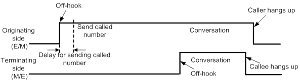
· Immediate start—After off-hook, the originating side waits for a specified period of time to send the called number to the terminating side. During this period of time, the originating side does not check whether the terminating side is ready to receive the called number. The terminating side enters off-hook state after receiving the called number.
Figure 3 Immediate start
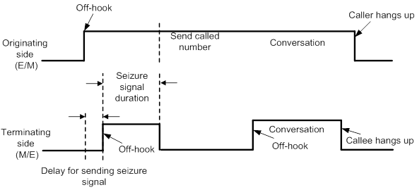
· Delay start—The originating side goes off-hook and seizes the trunk. After detecting the seizure signal from the originating side, the terminating side enters the off-hook state and remains in this state until it is ready to receive the called number. Then, the terminating side enters the on-hook state and sends a signal to indicate that the line is idle. After receiving the idle signal, the originating side sends the called number to the terminating side, which relays the call to the user phone.
Figure 4 Delay start
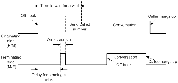
· Wink start—The terminating side remains in on-hook state until it receives the seizure signal from the originating side and then sends a wink to the originating side. After receiving the wink, the originating side sends the called number to the terminating side, which relays the call to the user phone.
Figure 5 Wink start
To configure the immediate start mode:
|
Step |
Command |
Remarks |
|
1. Enter system view. |
system-view |
N/A |
|
2. Enter E&M interface view. |
subscriber-line line-number |
N/A |
|
3. Configure the immediate start mode for the E&M interface. |
signal immediate |
The default is the immediate start mode. |
|
4. Set a delay for the originating side to wait to send DTMF tones in immediate start mode. |
delay send-dtmf milliseconds |
The default is 300 milliseconds. Use this command on the originating device. |
To configure the delay start mode:
|
Step |
Command |
Remarks |
|
1. Enter system view. |
system-view |
N/A |
|
2. Enter voice interface view. |
subscriber-line line-number |
N/A |
|
3. Specify the delay start mode for the E&M interface. |
signal delay |
The default is the immediate start mode. |
|
4. Set the seizure signal duration in delay start mode. |
delay hold milliseconds |
The default is 400 milliseconds. Use this command on the terminating device. |
|
5. Set the delay time from when the terminating side detects a seizure signal to when it sends the seizure signal in delay start mode. |
delay rising milliseconds |
The default is 300 milliseconds. Use this command on the terminating device. |
To configure the wink start mode:
|
Step |
Command |
Remarks |
|
1. Enter system view. |
system-view |
N/A |
|
2. Enter voice interface view. |
subscriber-line line-number |
N/A |
|
3. Specify the wink start mode for the E&M interface. |
signal wink |
The default is the immediate start mode. |
|
4. Set the delay time from when the terminating side receives a seizure signal to when it sends a wink signal in the wink start mode. |
delay send-wink milliseconds |
The default is 200 milliseconds. Use this command on the terminating device. |
|
5. Set the duration of a wink signal sent by the terminating side in wink start mode. |
delay wink-hold milliseconds |
The default is 500 milliseconds. Use this command on the terminating device. |
|
6. Set the timeout time for the originating side to wait for a wink signal after sending a seizure signal in the wink start mode. |
delay wink-rising milliseconds |
The default is 2000 milliseconds. Use this command on the originating device. |
Configuring E&M non-signaling mode
The E&M non-signaling mode is applied when the E&M interface of the peer device does not provide the M line and E line. In this mode, the E&M interface communicates with the peer device without signaling. You can configure the PLAR feature by using the private-line command to form a three-segment E&M virtual private line (E&M-VoIP-E&M). When a subscriber picks up the phone, the originating device directly dials the number specified by using the private-line command.
To configure E&M non-signaling mode:
|
Step |
Command |
Remarks |
|
1. Enter system view. |
system-view |
N/A |
|
2. Enter voice interface view. |
subscriber-line line-number |
N/A |
|
3. Specify the immediate start mode for the E&M interface. |
signal immediate |
The default is the immediate start mode. |
|
4. Enable E&M non-signaling mode. |
open-trunk { caller [ monitor interval ] | called } |
By default, E&M non-signaling mode is disabled. Configure the open-trunk caller [ monitor interval ] command on the originating device, and configure the open-trunk called command on the terminating device. |
|
5. Enable the PLAR feature. |
private-line string |
Use this command on the originating device. For more information about the PLAR feature, see "Configuring dial programs." |
Enabling E&M control signals pass-through
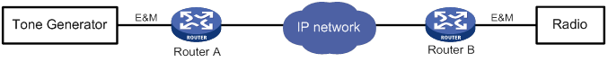
This feature operates only when the E&M non-signaling mode is enabled. As shown in Figure 6, an E&M virtual private line is established between the tone generator and the radio. Enable E&M control signals pass-through for Router A and Router B so that they can send seize and idle signals for the E&M virtual line over the IP network.
Figure 6 E&M analog control signals pass-through
To enable E&M control signals pass-through:
|
Step |
Command |
Remarks |
|
1. Enter system view. |
system-view |
N/A |
|
2. Enter voice interface view. |
subscriber-line line-number |
N/A |
|
3. Enable E&M control signals pass-through. |
passthrough |
By default, this feature is disabled. Configure this command on both the originating and terminating devices. |
Configuring the output gain of SLIC chip
|
Step |
Command |
Remarks |
|
1. Enter system view. |
system-view |
N/A |
|
2. Enter voice interface view. |
subscriber-line line-number |
N/A |
|
3. Set the output gain of the SLIC chip. |
slic-gain { 0 | 1 } |
Optional. The default is 0 (0.8 dB). This command controls signal amplification. |
Enabling E&M call logging
E&M call logging enables the device to log call events on E&M interfaces and send the log message to the information center. With the information center, you can set log message filtering and output rules, including output destinations. For more information about using the information center, see Network Management and Monitoring Configuration Guide.
To enable E&M interface logging:
|
Step |
Command |
Remarks |
|
1. Enter system view. |
system-view |
N/A |
|
2. Enter voice view. |
voice-setup |
N/A |
|
3. Enable E&M call logging. |
em log enable |
By default, E&M call logging is disabled. |
Configuring DTMF signaling
Dual tone multifrequency (DTMF) signaling uses a mixture of a high frequency tone and a lower frequency tone to represent a key on a keypad. Each column of keys is represented by a high frequency tone and each row of keys is represented by a low frequency tone. For example, as shown in Figure 7, the digit 1 is represented by the combination of a pure 697 Hz signal and a pure 1209 Hz signal. These DTMF tones offer good immunity to interference.
Figure 7 DTMF keypad frequencies
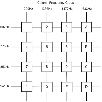
A DTMF tone must last a minimum of 45 milliseconds. A minimum interval of 23 milliseconds is required between two DTMF tones to make sure DTMF tones are recognizable. Such requirements are roughly the same in all countries. For more information, see the ITU-T Recommendation Q.24.
Configuring DTMF tone sending
|
Step |
Command |
Remarks |
|
1. Enter system view. |
system-view |
N/A |
|
2. Enter voice view. |
voice-setup |
N/A |
|
3. Set the duration of DTMF tones and the interval between DTMF tones. |
dtmf time {interval | persist } milliseconds |
The default duration and interval are both 120 milliseconds. |
|
4. Set the amplitude of DTMF tones. |
dtmf amplitude value |
The default is –9.0 dBm. |
Configuring DTMF tone detection
Perform this task to configure the threshold parameters and sensitivity level for DTMF detection.
· The threshold parameters are used to determine whether a DTMF tone is valid. The system calculates the spectrum shape of input DTMF signals and matches the spectrum shape with the threshold parameters. A DTMF tone is considered valid if it matches all threshold parameters.
· The sensitivity level is a trade-off between detection sensitivity and reliability. A higher DTMF detection sensitivity reduces the possibility of missing a true DTMF tone but increases the possibility of false detection. A lower DTMF detection sensitivity reduces the possibility of false detection but increases the possibility of missing a true DTMF tone.
To configure DTMF tone detection:
|
Step |
Command |
Remarks |
|
1. Enter system view. |
system-view |
N/A |
|
2. Enter voice interface view. |
subscriber-line line-number |
N/A |
|
3. Configure the threshold parameters for DTMF tone detection. |
dtmf threshold analog index value |
By default, indexes 0 to 12 correspond to 1400, 458, -9, -9, -9, -9, -3, -12, -12, 30, 300, 3200, and 375, respectively. This command is used by professional personnel to adjust the device in the case of DTMF tone detection failure. Typically, the default value is used. |
|
4. Set the DTMF tone detection sensitivity level. |
dtmf sensitivity-level { high | low | medium [ frequency-tolerance value ] } |
By default, the DTMF tone detection sensitivity is low. For the command and hardware compatibility, see Voice Command Reference. |
Adjusting parameters for analog voice interfaces
All configuration tasks in this section are optional.
Adjusting gains
You can adjust gains to control the amount of volume in the input or output direction.
|
|
IMPORTANT: To avoid call failures, adjust gains only if necessary and do it under the guidance of technical engineers. |
To adjust gains:
|
Step |
Command |
Remarks |
|
1. Enter system view. |
system-view |
N/A |
|
2. Enter analog voice interface view. |
subscriber-line line-number |
N/A |
|
3. Set the input gain. |
receive gain value |
The default is 0 dB. |
|
4. Set the output gain. |
transmit gain value |
The default is 0 dB. |
Adjusting timing parameters
|
Step |
Command |
Remarks |
|
1. Enter system view. |
system-view |
N/A |
|
2. Enter analog voice interface view. |
subscriber-line line-number |
N/A |
|
3. Set the interval between off-hook and dialing the first digit. |
timer first-dial seconds |
The default is 10 seconds. This command applies only to FXO and FXS interfaces. |
|
4. Set the maximum interval for dialing the next digit. |
timer dial-interval interval |
The default is 10 seconds. |
|
5. Set the maximum duration for playing ringback tones. |
timer ring-back seconds |
The default is 60 seconds. |
|
6. Set the dial delay time. |
delay start-dial seconds |
The default is 1 second. This command applies only to FXO and FXS interfaces. |
|
7. Set the hookflash time range. |
timer hookflash-detect hookflash-range |
By default, the hookflash time range is 50 to 180 milliseconds. If an on-hook condition lasts for a period that falls within the hookflash time range, it is considered a hookflash. This command applies only to FXS interfaces. |
|
8. Set the maximum duration the terminating device waits for the first digit. |
timer wait-digit { seconds | infinity } |
The default is 5 seconds. This command applies only to E&M interfaces. |
Enabling the comfortable noise feature
You can enable this feature to generate comfortable background noise to replace the silent gaps during a conversation.
To enable the comfortable noise feature:
|
Step |
Command |
Remarks |
|
1. Enter system view. |
system-view |
N/A |
|
2. Enter analog voice interface view. |
subscriber-line line-number |
N/A |
|
3. Enable the comfortable noise feature. |
cng-on |
By default, this feature is enabled. |
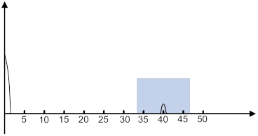
Configuring echo cancellation
An echo is the sound of your own voice going back to the phone receiver when you are speaking. The echo cancellation feature can alleviate the echo problem.
The time when an echo occurs and the size of the echo are relatively fixed. As shown in Figure 8, there is a voice signal at time 0, and an echo occurs after about 40 milliseconds (ms). To cancel this echo, perform the following tasks:
· Set the echo cancellation delay (the time between when an interface sends out a signal and when the interface receives an echo) to 33 ms.
· Set the echo cancellation coverage to 16 ms.
Configuring the echo cancellation feature
|
Step |
Command |
Remarks |
|
1. Enter system view. |
system-view |
N/A |
|
2. Enter analog voice interface view. |
N/A |
|
|
3. Enable the echo cancellation feature. |
echo-canceler enable |
By default, this feature is enabled. |
|
4. Set the echo cancellation delay. |
echo-canceler delay milliseconds |
The default is 0 milliseconds. |
|
5. Set the echo cancellation coverage. |
echo-canceler tail-length milliseconds |
The default is 128 milliseconds. |
Adjusting echo cancellation parameters
Table 1 describes how to adjust echo cancellation parameters for different symptoms.
Table 1 Adjusting echo cancellation parameters
|
Symptom |
Parameters adjusted |
|
A user hears echoes or loud background noises from the peer when speaking. |
Speed up the convergence of comfortable noise amplitudes. |
|
There are loud environment noises. |
Increase the maximum amplitude of comfortable noises. |
|
A user hears echoes when speaking. |
Enlarge the mixture proportion control factor of comfortable noises. |
|
There are echoes when both parties speak at the same time. |
Enlarge the two-way judgment threshold. |
To adjust echo cancellation parameters:
|
Step |
Command |
Remarks |
|
1. Enter system view. |
system-view |
N/A |
|
2. Enter voice view. |
voice-setup |
N/A |
|
3. Adjust echo cancellation parameters. |
echo-canceler { convergence-rate value | max-amplitude value | mix-proportion-ratio value | talk-threshold value } |
By default: · The convergence rate of comfort noise amplitude is 0. · The maximum amplitude of comfort noise is 256. · The comfort noise mixture proportion control factor is 100. · The two-way judgment threshold is 1. These parameters take effect only when the echo-canceler enable command is configured. |
Enabling the nonlinear feature of echo cancellation
After echo cancellation is enabled, nonlinear parts in the line can cause residual echo. The nonlinear feature (also called residual echo suppression) can remove the residual echo.
To enable the nonlinear feature of echo cancellation:
|
Step |
Command |
Remarks |
|
1. Enter system view. |
system-view |
N/A |
|
2. Enter analog voice interface view. |
subscriber-line line-number |
N/A |
|
3. Enable the nonlinear feature of echo cancellation. |
nlp-on |
By default, this feature is enabled. This command takes effect only when the echo-canceler enable command is configured. This command is not supported on the following interface modules: · DSIC-4FXS1FXO. · HMIM-16FXS. · HMIM-8FXS8FXO. · SIC-2FXS1FXO. |
Enabling PCM pass-through
The following matrix shows the feature and hardware compatibility:
|
Hardware |
PCM pass-through compatibility |
|
MSR810/810-W/810-W-DB/810-LM/810-W-LM/810-10-PoE/810-LM-HK/810-W-LM-HK/810-LMS/810-LUS |
No |
|
MSR2600-6-X1/2600-10-X1 |
No |
|
MSR 2630 |
No |
|
MSR3600-28/3600-51 |
No |
|
MSR3600-28-SI/3600-51-SI |
No |
|
MSR3610-X1/3610-X1-DP/3610-X1-DC/3610-X1-DP-DC |
No |
|
MSR 3610/3620/3640/3660 |
Yes (supported only on routers installed with E&M interface modules.) |
|
MSR5620/5660/5680 |
Yes (supported only on routers installed with E&M interface modules.) |
|
Hardware |
PCM pass-through compatibility |
|
MSR810-LM-GL |
No |
|
MSR810-W-LM-GL |
No |
|
MSR830-6EI-GL |
No |
|
MSR830-10EI-GL |
No |
|
MSR830-6HI-GL |
No |
|
MSR830-10HI-GL |
No |
|
MSR2600-6-X1-GL |
No |
|
MSR3600-28-SI-GL |
No |
This feature is supported only when G.711 A-Law is used. For this feature to take effect on a subcard, you must reboot the subcard. To check whether this feature takes effect, use the display device verbose command.
To enable PCM pass-through:
|
Step |
Command |
Remarks |
|
1. Enter system view. |
N/A |
|
|
2. Enter voice view. |
N/A |
|
|
3. Enable PCM pass-through. |
·
Centralized devices in standalone mode: ·
Distributed devices in standalone
mode/centralized devices in IRF mode: ·
Distributed devices in IRF mode: |
By default, PCM pass-through is disabled. |
Displaying and maintaining analog voice interfaces
Execute display commands in any view.
|
Task |
Command |
|
Display information about analog voice interfaces. |
display voice subscriber-line |
Analog voice interface configuration examples
Two-dial configuration example for the FXO interface
Network requirements
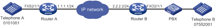
As shown in Figure 9, Router A and Router B are connected through an IP network and can reach each other. The PBX is configured with a trunk number 07552003.
Configure the two routers to enable Telephone B to establish a call with Telephone A through two dials.
Configuration procedure
1. On Router A, configure the local number as 0101001 for POTS entity 1001, and bind FXS interface line 2/1/1 to the POTS entity.
<RouterA> system-view
[RouterA] voice-setup
[RouterA-voice] dial-program
[RouterA-voice-dial] entity 1001 pots
[RouterA-voice-dial-entity1001] match-template 0101001
[RouterA-voice-dial-entity1001] line 2/1/1
2. Configure Router B:
# Configure the called number as 0101001 for VoIP entity 010, and configure the destination IP address as 1.1.1.1.
<RouterB> system-view
[RouterB] voice-setup
[RouterB-voice] dial-program
[RouterB-voice-dial] entity 010 voip
[RouterB-voice-dial-entity10] match-template 0101001
[RouterB-voice-dial-entity10] address sip ip 1.1.1.1
[RouterB-voice-dial-entity10] quit
# Configure the local number as 07552001 for POTS entity 2001, and bind FXO interface line 2/1/1 to POTS entity 2001.
[RouterB-voice-dial] entity 2001 pots
[RouterB-voice-dial-entity2001] match-template 07552001
[RouterB-voice-dial-entity2001] line 2/1/1
# Configure the number sending mode as all.
[RouterB-voice-dial-entity2001] send-number all
Verifying the configuration
# Dial 07552003 from Telephone B.
# After hearing a dial tone, dial 0101001 (Telephone A) from Telephone B to verify that Telephone B can establish calls with Telephone A through two dials.
FXO interface PLAR configuration example
Network requirements
As shown in Figure 10, Router A and Router B are connected through an IP network and can reach each other. The PBX is configured with a trunk number 07552003.
Configure PLAR for the FXO interface of Router B. When the user of Telephone B dials 07552003, the FXO interface automatically calls Telephone A.
Configuration procedure
1. On Router A, configure the local number as 0101001 for POTS entity 1001, and bind FXS interface line 2/1/1 to the POTS entity.
<RouterA> system-view
[RouterA] voice-setup
[RouterA-voice] dial-program
[RouterA-voice-dial] entity 1001 pots
[RouterA-voice-dial-entity1001] match-template 0101001
[RouterA-voice-dial-entity1001] line 2/1/1
2. Configure Router B:
# Configure the called number as 0101001 for VoIP entity 010, and configure the destination IP address as 1.1.1.1.
<RouterB> system-view
[RouterB] voice-setup
[RouterB-voice] dial-program
[RouterB-voice-dial] entity 010 voip
[RouterB-voice-dial-entity10] match-template 0101001
[RouterB-voice-dial-entity10] address sip ip 1.1.1.1
[RouterB-voice-dial-entity10] quit
# Configure the local number as 07552001 for POTS entity 2001, and bind FXO interface line 2/1/1 to the POTS entity.
[RouterB-voice-dial] entity 2001 pots
[RouterB-voice-dial-entity2001] match-template 07552001
[RouterB-voice-dial-entity2001] line 2/1/1
# Configure the number sending mode as all.
[RouterB-voice-dial-entity2001] send-number all
# Enable the PLAR feature and configure the delay off-hook mode for the FXO interface.
[RouterB] subscriber-line 2/1/1
[RouterB-subscriber-line2/1/1] private-line 0101001
[RouterB-subscriber-line2/1/1] hookoff-mode delay
Verifying the configuration
# Dial 07552003 from Telephone B to verify that Telephone B can automatically establish calls with Telephone A through the PLAR feature.
E&M interface configuration example
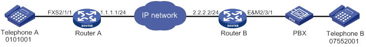
Network requirements
As shown in Figure 11, Router A and Router B are connected through an IP network and can reach each other.
Configure the two routers to enable Telephone A and Telephone B to establish calls.
Configuration procedure
1. Configure Router A:
# Configure the called number as 07552001 for VoIP entity 0755, and configure the destination IP address as 2.2.2.2.
<RouterA> system-view
[RouterA] voice-setup
[RouterA-voice] dial-program
[RouterA-voice-dial] entity 0755 voip
[RouterA-voice-dial-entity755] match-template 07552001
[RouterA-voice-dial-entity755] address sip ip 2.2.2.2
[RouterA-voice-dial-entity755] quit
# Configure the local number as 0101001 for POTS entity 1001, and bind FXS interface line 2/1/1 to the POTS entity.
[RouterA-voice-dial] entity 1001 pots
[RouterA-voice-dial-entity1001] match-template 0101001
[RouterA-voice-dial-entity1001] line 2/1/1
2. Configure Router B:
# Configure the called number as 0101001 for VoIP entity 010, and configure the destination IP address as 1.1.1.1.
<RouterB> system-view
[RouterB] voice-setup
[RouterB-voice] dial-program
[RouterB-voice-dial] entity 010 voip
[RouterB-voice-dial-entity10] match-template 0101001
[RouterB-voice-dial-entity10] address sip ip 1.1.1.1
[RouterB-voice-dial-entity10] quit
# Configure the local number as 07552001 for POTS entity 2001, and bind E&M interface line 2/3/1 to the POTS entity.
[RouterB-voice-dial] entity 2001 pots
[RouterB-voice-dial-entity2001] match-template 07552001
[RouterB-voice-dial-entity2001] send-number all
[RouterB-voice-dial-entity2001] line 2/3/1
[RouterB-voice-dial-entity2001] return
# Enter the view of E&M interface 5/0. The E&M interface must have the same configuration as the connected PBX.
<RouterB> system-view
[RouterB] subscriber-line 2/3/1
# Configure the wink start mode.
[RouterB-subscriber-line2/3/1] signal wink
# Configure the 4-wire cable type (optional, because the default is the 4-wire cable type).
[RouterB-subscriber-line2/3/1] cable 4-wire
# Configure the signal type as 5 (optional, because the default is 5).
[RouterB-subscriber-line2/3/1] type 5
Verifying the configuration
# Dial 07552001 (Telephone B) from Telephone A to verify that Telephone A can establish calls with Telephone B.
# Dial 0101001 (Telephone A) from Telephone B to verify that Telephone B can establish calls with Telephone A.
E&M non-signaling mode configuration example
Network requirements
As shown in Figure 12, configure the PLAR mode for the E&M interface on Router A. When the user of Telephone A picks up the handset, the E&M interface automatically calls Telephone B.
Configuration procedure
1. Configure Router A:
# Configure the called number as 2000 for VoIP entity 2000, and configure the destination IP address as 2.2.2.2.
<RouterA> system-view
[RouterA] voice-setup
[RouterA-voice] dial-program
[RouterA-voice-dial] entity 2000 voip
[RouterA-voice-dial-entity2000] match-template 2000
[RouterA-voice-dial-entity2000] address sip ip 2.2.2.2
[RouterA-voice-dial-entity2000] quit
# Configure the local number as 1000 for POTS entity 1000, and bind E&M interface line 2/3/1 to the POTS entity.
[RouterA-voice-dial] entity 1000 pots
[RouterA-voice-dial-entity1000] match-template 1000
[RouterA-voice-dial-entity1000] line 2/3/1
[RouterA-voice-dial-entity1000] return
# Enter the view of the E&M interface line 2/3/1.
<RouterA> system-view
[RouterA] subscriber-line 2/3/1
# Configure the immediate start mode (optional, because the default is the immediate start mode).
[RouterA-subscriber-line2/3/1] signal immediate
# Enable the PLAR feature.
[RouterA-subscriber-line2/3/1] private-line 2000
# Enable the E&M non-signaling mode.
[RouterA-subscriber-line2/3/1] open-trunk caller
# Enable E&M control signals pass-through.
[RouterA-subscriber-line2/3/1] passthrough
# Disable the echo cancellation feature.
[RouterA-subscriber-line2/3/1] undo echo-canceler enable
2. Configure Router B:
# Configure the called number as 1000 for VoIP entity 1000, and configure the destination IP address as 1.1.1.1.
<RouterB> system-view
[RouterB] voice-setup
[RouterB-voice] dial-program
[RouterB-voice-dial] entity 1000 voip
[RouterB-voice-dial-entity1000] match-template 1000
[RouterB-voice-dial-entity1000] address sip ip 1.1.1.1
[RouterB-voice-dial-entity1000] quit
# Configure the local number as 2000 for POTS entity 2000, and bind E&M interface line 2/3/1 to the POTS entity.
[RouterB-voice-dial] entity 2000 pots
[RouterB-voice-dial-entity2000] match-template 2000
[RouterB-voice-dial-entity2000] line 2/3/1
[RouterB-voice-dial-entity2000] return
# Enter the view of the E&M interface line 2/3/1.
<RouterB> system-view
[RouterB] subscriber-line 2/3/1
# Configure the immediate start mode. The default is the immediate start mode.
[RouterB-subscriber-line2/3/1] signal immediate
# Enable the E&M non-signaling mode.
[RouterB-subscriber-line2/3/1] open-trunk called
# Enable E&M control signals pass-through.
[RouterB-subscriber-line2/3/1] passthrough
# Disable the echo cancellation feature.
[RouterB-subscriber-line2/3/1] undo echo-canceler enable
Verifying the configuration
# Pick up the handset of Telephone A to verify that Telephone A can automatically establish calls with Telephone B through the PLAR feature.
FXS&FXO 1:1 binding configuration example
Network requirements
As shown in Figure 13, Telephone A calls Telephone B through the IP network. When the IP network is unavailable, Telephone A uses the bound FXO interface to call Telephone B through the PSTN network.
Configuration procedure
1. Configure Router A:
# Configure the called number template as 210…. for VoIP entity 210, and configure the destination IP address as 192.168.0.76.
<RouterA> system-view
[RouterA] voice-setup
[RouterA-voice] dial-program
[RouterA-voice-dial] entity 210 voip
[RouterA-voice-dial-entity210] match-template 210....
[RouterA-voice-dial-entity210] address sip ip 192.168.0.76
[RouterA-voice-dial-entity210] quit
# Configure the local number as 0101001 for POTS entity 0101001, and bind the FXS interface line 2/1/1 to the POTS entity.
[RouterA-voice-dial] entity 0101001 pots
[RouterA-voice-dial-entity101001] match-template 0101001
[RouterA-voice-dial-entity101001] line 2/1/1
[RouterA-voice-dial-entity101001] quit
# Configure the called number template as .T for POTS entity 211 used for call backup on FXO interface line 2/2/1, and configure the permitted calling number as 0101001.
[RouterA-voice-dial] entity 211 pots
[RouterA-voice-dial-entity211] match-template .T
[RouterA-voice-dial-entity211] line 2/2/1
[RouterA-voice-dial-entity211] send-number all
[RouterA-voice-dial-entity211] caller-permit 0101001
[RouterA-voice-dial-entity211] quit
[RouterA-voice-dial] quit
[RouterA-voice] quit
# Enable the PLAR feature for the FXO interface line 2/2/1, and bind the FXS interface line 2/1/1 to the FXO interface line 2/2/1.
[RouterA] subscriber-line 2/2/1
[RouterA-subscriber-line2/2/1] private-line 0101001
[RouterA-subscriber-line2/2/1] hookoff-mode delay bind 2/1/1
2. Configure Router B:
# Configure the called number template as 010…. for VoIP entity 010, and configure the destination IP address as 192.168.0.71.
<RouterB> system-view
[RouterB] voice-setup
[RouterB-voice] dial-program
[RouterB-voice-dial] entity 010 voip
[RouterB-voice-dial-entity10] match-template 010....
[RouterB-voice-dial-entity10] address sip ip 192.168.0.71
[RouterB-voice-dial-entity10] quit
# Configure the local number as 2101002 for POTS entity 2101002, and bind the FXS interface line 2/1/1 to the POTS entity.
[RouterB-voice-dial] entity 2101002 pots
[RouterB-voice-dial-entity2101002] match-template 2101002
[RouterB-voice-dial-entity2101002] line 2/1/1
[RouterB-voice-dial-entity2101002] quit
# Configure the called number template as .T for POTS entity 011 used for call backup on FXO interface line 2/2/1, and configure the permitted calling number as 2101002.
[RouterB-voice-dial] entity 011 pots
[RouterB-voice-dial-entity11] match-template .T
[RouterB-voice-dial-entity11] line 2/2/1
[RouterB-voice-dial-entity11] send-number all
[RouterB-voice-dial-entity11] caller-permit 2101002
[RouterB-voice-dial-entity11] quit
[RouterB-voice-dial] quit
[RouterB-voice] quit
# Enable the PLAR feature for the FXO interface line 2/2/1, and bind the FXS interface line 2/1/1 to the FXO interface line 2/2/1.
[RouterB] subscriber-line 2/2/1
[RouterB-subscriber-line2/2/1] private-line 2101002
[RouterB-subscriber-line2/2/1] hookoff-mode delay bind 1/0
Verifying the configuration
# When the IP network is available, place a call to verify that the call is established through the IP network.
# When the IP network is unavailable, place a call to verify that the call is established through the PSTN.
Configuring digital voice interfaces
Overview
Digital voice interfaces include E1, T1, and BSV interfaces.
E1 and T1 interfaces
E1 interfaces (also called VE1 interfaces) and T1 interfaces (also called VT1 interfaces) can connect to the PSTN as trunk interfaces. An E1 interface provides 32 timeslots and 2.048 Mbps bandwidth. A T1 interface provides 24 timeslots and 1.544 Mbps bandwidth. ITU-T E1 is used mainly in Europe and China. ANSI T1 is used mainly in America, Canada, and Japan.
E1/T1 voice transmission allows a router to provide more communication channels, which improves router utilization.
Figure 14 shows a typical network for E1/T1 interfaces.

BSV interfaces
BRI S/T voice (BSV) interfaces can compress, send, receive, and decompress voice packets. BSV interfaces connect to PBXs as trunk interfaces. A BSV interface provides two B channels and one D channel (2B+D) and supports only DSS1 signaling.
Compatibility information
Feature and hardware compatibility
|
Hardware |
Digital voice interface compatibility |
|
MSR810/810-W/810-W-DB/810-LM/810-W-LM/810-10-PoE/810-LM-HK/810-W-LM-HK/810-LMS/810-LUS |
No |
|
MSR2600-6-X1/2600-10-X1 |
Yes |
|
MSR 2630 |
Yes |
|
MSR3600-28/3600-51 |
Yes |
|
MSR3600-28-SI/3600-51-SI |
No |
|
MSR3610-X1/3610-X1-DP/3610-X1-DC/3610-X1-DP-DC |
No |
|
MSR 3610/3620/3620-DP/3640/3660 |
Yes |
|
MSR5620/5660/5680 |
Yes (not supported on the router installed with an SPU600-X1 card.) |
|
Hardware |
Digital voice interface compatibility |
|
MSR810-LM-GL |
No |
|
MSR810-W-LM-GL |
No |
|
MSR830-6EI-GL |
No |
|
MSR830-10EI-GL |
No |
|
MSR830-6HI-GL |
No |
|
MSR830-10HI-GL |
No |
|
MSR2600-6-X1-GL |
Yes |
|
MSR3600-28-SI-GL |
No |
Command and hardware compatibility
Commands and descriptions for centralized devices apply to the following routers:
· MSR810/810-W/810-W-DB/810-LM/810-W-LM/810-10-PoE/810-LM-HK/810-W-LM-HK/810-LMS/810-LUS.
· MSR2600-6-X1/2600-10-X1.
· MSR 2630.
· MSR3600-28/3600-51.
· MSR3600-28-SI/3600-51-SI.
· MSR3610-X1/3610-X1-DP/3610-X1-DC/3610-X1-DP-DC.
· MSR 3610/3620/3620-DP/3640/3660.
· MSR810-LM-GL/810-W-LM-GL/830-6EI-GL/830-10EI-GL/830-6HI-GL/830-10HI-GL/2600-6-X1-GL/3600-28-SI-GL.
Commands and descriptions for distributed devices apply to the following routers:
· MSR5620.
· MSR 5660.
· MSR 5680.
Configuration task lists
E1 and T1 interface configuration task list
|
Tasks at a glance |
|
(Optional.) Configuring basic settings |
|
(Required.) Perform one of the following tasks: · Configuring basic parameters for an E1 interface: ? Configuring a TDM clock source ? Configuring other parameters · Configuring basic parameters for a T1 interface: |
|
(Required.) Configuring a timeslot set: |
|
(Required.) Perform one of the following tasks: ? Configuring basic R2 signaling parameters ? Configuring R2 digital line signaling |
|
(Required.) Binding a digital voice interface to a POTS entity |
|
(Optional.) Configuring reverse charging |
|
(Optional.) Enabling the router to treat DISCONNECT messages with PI 8 as standard DISCONNECT messages |
|
(Optional.) Adjust ing parameters for digital voice interfaces: |
BSV interface configuration task list
|
Tasks at a glance |
|
(Optional.) Configuring basic settings |
|
(Required.) Configuring a BSV interface |
|
(Required.) Configuring the ISDN protocol |
|
(Required.) Binding a digital voice interface to a POTS entity |
|
(Optional.) Enabling the router to treat DISCONNECT messages with PI 8 as standard DISCONNECT messages |
|
(Optional.) Adjust ing parameters for digital voice interfaces |
Configuring basic settings
|
Step |
Command |
Remarks |
|
1. Enter system view. |
system-view |
N/A |
|
2. Enter digital voice interface view. |
N/A |
|
|
3. Configure a description for the digital voice interface. |
description text |
By default, the description of a digital voice interface is interface name Interface. |
|
4. Restore the default settings for the digital voice interface. |
default |
N/A |
|
5. Bring up the digital voice interface. |
undo shutdown |
By default, a digital voice interface is up. |
Configuring basic parameters for an E1 interface
This section describes basic E1 interface settings.
Configuring a TDM clock source
E1 interfaces must use a common TDM clock source during timeslot interchange to prevent frame slips and bit errors.
When both E1 and T1 interface modules are present on a device, all the E1 or T1 SIC interface modules are a subsystem, and each E1 or T1 HMIM interface module is a subsystem. Each subsystem determines the clock source according to the following rules:
· If the line keyword is specified for all interfaces, the clock on the interface with the lowest number is used. If the interface goes down, the clock on the interface with the second lowest number is used.
· If the line and primary keywords are specified for one interface and the line or internal keyword is specified for all other interfaces, the clock on that one interface is used.
· If the line keyword is specified for one interface and the internal keyword is specified for all other interfaces, the clock on that one interface is used.
· The clock source of only one interface can be set to line primary.
The TDM clock sources on the local and peer devices must match. For example, if you set the clock source to line for a subsystem on the local device, you must set the clock source to internal on the peer device, and vice versa.
To configure a TDM clock source for an E1 interface:
|
Step |
Command |
Remarks |
|
1. Enter system view. |
system-view |
N/A |
|
2. Enter E1 interface view. |
controller e1 number |
N/A |
|
3. Configure a TDM clock source for the E1 interface. |
tdm-clock { internal | line [ primary ] } |
The default is internal. |
Configuring other parameters
|
Step |
Command |
Remarks |
|
1. Enter system view. |
system-view |
N/A |
|
2. Enter E1 interface view. |
controller e1 number |
N/A |
|
3. Configure a description. |
description text |
The default is interface name Interface. |
|
4. Configure the framing format. |
frame-format { crc4 | no-crc4 } |
The default is no-crc4. |
|
5. Set the line coding format. |
code { ami | hdb3 } |
The default is hdb3. |
|
6. Set the cable type. |
cable { long | short } |
The default is long. |
|
7. Configure the link idle code type. |
idle-code { 7e | ff } |
The default is 0x7E. |
|
8. Set the interframe filling tag type. |
itf type { 7e | ff } |
The default is 0x7E. |
|
9. (Optional.) Enable loopback and set the loopback mode. |
loopback { local | payload | remote } |
By default, loopback is disabled. |
|
10. Restore the default settings for the E1 interface. |
default |
N/A |
|
11. Shut down the E1 interface. |
undo shutdown |
By default, an E1 interface is up. |
Configuring basic parameters for a T1 interface
This section describes the basic T1 interface settings.
Configuring a TDM clock source
A T1 interface has the same TDM clock source configuration as an E1 interface. For more information, see "Configuring a TDM clock source."
To configure a TDM clock source:
|
Step |
Command |
Remarks |
|
1. Enter system view. |
system-view |
N/A |
|
2. Enter T1 interface view. |
controller t1 number |
N/A |
|
3. Configure a TDM clock source for the T1 interface. |
tdm-clock { internal | line [ primary ] } |
The default is internal. |
Configuring other parameters
|
Step |
Command |
Remarks |
|
1. Enter system view. |
system-view |
N/A |
|
controller t1 number |
N/A |
|
|
3. Configure a description. |
description text |
The default is interface name Interface. |
|
4. Configure the framing format. |
frame-format { esf | sf } |
The default is esf. |
|
5. Set the line coding format. |
code { ami | b8zs } |
The default is b8zs. |
|
6. Set the cable type. |
cable { long | 0db | -7.5db | -15db | -22.5db | short | 133ft | 266ft | 399ft | 533ft | 655ft } |
The default is long 0db. |
|
7. Set the interframe filling tag type. |
itf type { 7e | ff } |
The default is 0x7E. |
|
8. Set alarm thresholds. |
alarm-threshold { ais { level-1 | level-2 } | lfa { level-1 | level-2 | level-3 | level-4 } | los { pulse-detection | pulse-recovery } value } |
By default: · For LOS alarms, the threshold of pulse-detection is 176 and the threshold of pulse-recovery is 22. If the number of pulses detected during the total length of 176 pulse detection intervals is smaller than 22 (the pulse-recovery threshold), a LOS alarm occurs. · Both AIS alarm threshold and LFA alarm threshold are level-1. |
|
9. Enable loopback and set the loopback mode. |
loopback { local | payload | remote } |
By default, loopback is disabled. |
|
10. Restore the default settings for the T1 interface. |
default |
N/A |
|
11. Bring up the T1 interface. |
undo shutdown |
By default, a T1 interface is up. |
Configuring a BSV interface
A BSV interface can generate basic rate interfaces (BRIs) and logical digital voice interfaces.
· BRI—Has the same logical characteristics as an ISDN BRI but can be used only for voice transmission. You can configure ISDN parameters on a BRI interface.
· Logical digital voice interface—Can be configured with voice commands. A logical digital voice interface has two subinterfaces, which correspond to the two B channels. You cannot configure commands on the subinterfaces, but you can use the display voice subscriber-line line-number.subnumber command to view the call state of a subinterface.
|
Step |
Command |
Remarks |
|
1. Enter system view. |
system-view |
N/A |
|
2. Enter BRI interface view. |
interface bri interface-number |
N/A |
|
3. (Optional.) Configure a description for the interface. |
description text |
The default is interface name Interface. |
|
4. (Optional.) Enable loopback detection for B channels. |
loopback { b1 | b2 | both } |
By default, loopback detection is disabled. |
|
5. (Optional.) Configure the expected bandwidth of the interface. |
bandwidth bandwidth-value |
The default is 0 kbps. |
|
6. Set the MTU of the interface. |
mtu size |
The default is 1500 bytes. |
|
7. Set the polling interval for the interface. |
timer-hold seconds |
The default is 10 seconds. |
|
8. (Optional.) Restore the default settings for the interface. |
default |
N/A |
|
9. Bring up the interface. |
undo shutdown |
By default, a BRI interface is up. |
|
10. (Optional.) Activate the interface. |
activate |
By default, a BRI interface is not activated. |
For more information about these commands, see Interface Command Reference.
Configuring a timeslot set
Creating a timeslot set
After you create a timeslot set and configure its signaling type on an E1 interface, the system automatically creates a logical digital voice interface. Timeslot 0 is used for frame synchronization, timeslot 16 is used to transmit signaling, and the other 30 timeslots are used to transmit voice packets.
A T1 interface is used in a similar way to an E1 interface, except that it has 24 timeslots and timeslot 24 is used to transmit signaling.
Only RS signaling can be configured for a timeslot set.
To create a timeslot set:
|
Step |
Command |
Remarks |
|
1. Enter system view. |
system-view |
N/A |
|
2. Enter E1 or T1 interface view. |
controller { e1 | t1 } number |
N/A |
|
3. Create a timeslot set and enable R2 signaling for it. |
timeslot-set ts-set-number timeslot-list timeslots-list signal r2 |
Configuring a logical digital voice interface
The system automatically creates a logical voice interface in the form of E1/T1 interface number:timeslot set number for a timeslot set.
To configure a logical digital voice interface:
|
Step |
Command |
Remarks |
|
1. Enter system view. |
system-view |
N/A |
|
2. Enter digital voice interface view. |
subscriber-line number:ts-set-number |
N/A |
|
3. Configure a companding law for PCM. |
pcm { a-law | μ-law } |
The default is a-law for logical digital voice interfaces of E1 interfaces and μ-law for logical digital voice interfaces of T1 interfaces. |
Configuring R2 signaling
ITU-T recommendations Q.400 through Q.490 define the R2 signaling standards. However, the R2 signaling standards implemented in different countries and regions are ITU variants.
In R2 signaling, the calling side acts as the originating PBX, and the called side acts as the terminating PBX. Signaling sent by the originating PBX is called forward signaling, and signaling sent by the terminating PBX is called backward signaling, as shown in Figure 15.
Figure 15 R2 signaling elements
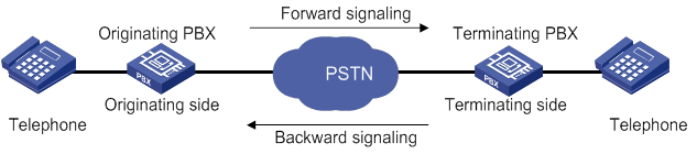
R2 signaling includes digital line signaling and interregister signaling. Digital line signaling conveys status information about E1 trunks to describe whether the trunks are seized, released, or blocked. Interregister signaling transmits and requests calling and called numbers.
ITU-T digital line signaling
Digital line signaling monitors the state of a trunk and controls calls. It can identify the following state changes:
· The calling party goes off-hook and seizes the line.
· The called party goes off-hook and answers the call.
· The calling party releases the call.
· The called party releases the call.
Digital line signaling sets the line to be idle or seized according to the state of the trunk. This signaling is transmitted through timeslot 16. The two transmission directions of each line have four bits (A, B, C and D) as flag bits, with C and D bits fixed to 01. The forward line signaling adopts af and bf bits, and the backward line signaling adopts ab and bb bits, as shown in Table 2.
Table 2 Line signaling bit description
|
Bit |
Description |
Value = 0 |
Value = 1 |
|
af |
Identifies the state of the originating device and indicates the state of the calling line. |
Off-hook, seized |
On-hook (idle) |
|
bf |
Indicates a fault state from the originating side to the terminating side. |
Normal |
Faulty |
|
ab |
Indicates the state of the called line (on-hook or off-hook). |
Off-hook by called party |
On-hook by called party |
|
bb |
Indicates the state of the terminating device (idle or seized). |
Idle |
Seized or blocked |
Table 3 State code of line signaling
|
State of the circuit |
Signaling code |
|||
|
Forward |
Backward |
|||
|
af |
bf |
ab |
bb |
|
|
Idle or release |
1 |
0 |
1 |
0 |
|
Seized |
0 |
0 |
1 |
0 |
|
Seizure-ack |
0 |
0 |
1 |
1 |
|
Answer |
0 |
0 |
0 |
1 |
|
Clear-back |
0 |
0 |
1 |
1 |
|
Clear-forward |
1 |
0 |
0/1 |
1 |
|
Blocked |
1 |
0 |
1 |
1 |
|
Unblocked |
1 |
0 |
1 |
0 |
R2 digital line signaling exchange includes the following processes:
· Call establishment.
When the circuit is idle, the originating side sends a forward seizure signal (00) to the terminating side, and the terminating side sends back a seizure acknowledgment signal (11). Then the circuit is seized, and interregister signaling exchange begins. When the called party picks up the phone, the terminating side sends a backward answer signal (01). After the originating side recognizes the received signal, it establishes the call.
Figure 16 Call establishment
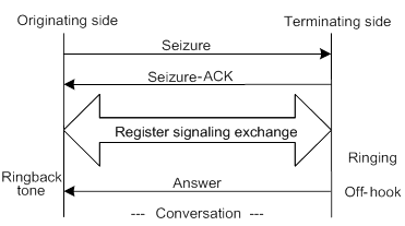
· Call release at the originating side.
The originating side sends a clear-forward signal 10. When the terminating side recognizes the clear-forward signal, it sends a backward signal 10. When the originating side recognizes the backward signal 10, it releases the call.
Figure 17 Call release at originating side
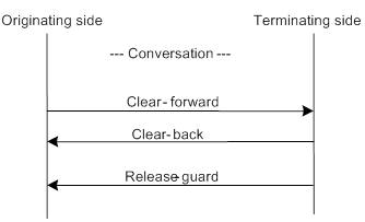
· Call release at the terminating side.
The terminating side sends a clear-back signal 11 to the originating side, and the originating side sends back a clear-forward signal 10. When the terminating side recognizes the forward signal 10, it sends a release-guard signal 10. When the originating side recognizes the release-guard signal 10, it releases the call.
Figure 18 Call release at terminating side
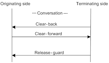
· Blocking in idle state or during conversation.
After the originating side receives a blocking signal 11 from the terminating side when the circuit is idle or during conversation, the circuit is blocked. In this case, the originating side still sends the forward signal 10 to indicate that the line is idle. When the terminating side unblocks the circuit, it sends a backward signal 10 to indicate that the line is idle. The originating side maintains the forward signal 10 and unblocks the local-end circuit for the next call.
ITU-T interregister signaling
Interregister signaling transmits and requests calling and called numbers. It adopts the multifrequency compelled (MFC) mode and includes forward signaling and backward signaling. Forward signaling exchange includes Group I and Group II, and backward signaling exchange includes Group A and Group B. When the originating side recognizes the seizure acknowledgment signal, interregister signaling begins to send the first digit of the called number, and waits for the response of Group A signaling from the terminating side.
· Group I forward signals—Include connection control signals and digit signals.
Table 4 Forward Group I signals
|
Designation |
Definition |
|
I-1 through I-10 |
Digits 1, 2, 3, 4, 5, 6, 7, 8, 9, and 0, responsible for sending number information to the terminating side. |
|
I-11 |
Spare for national use. |
|
I-12 |
Request refused. |
|
I-13 |
Connected to tested device. |
|
I-14 |
Spare for national use. |
|
I-15 |
Address identification terminator and pulse terminator (used in international calls). |
· Group A backward signals—Control signals used for controlling and acknowledging Group I forward signals.
Table 5 Group A backward signals
|
Designation |
Definition |
|
A-1 |
Send next digit. |
|
A-2 |
Send last but one digit. |
|
A-3 |
Address-complete; changeover to reception of Group B signals. |
|
A-4 |
Congestion in the national network. |
|
A-5 |
Send calling party's category. |
|
A-6 |
Address-complete, charge, and set up speech conditions. |
|
A-7 |
Send last but two digits. |
|
A-8 |
Send last but three digits. |
|
A-9 |
Spare for national use. |
|
A-10 |
Spare for national use. |
|
A-11 |
Send country code indicator. |
|
A-12 |
Send language or discrimination digit. |
|
A-13 |
Send nature of circuit. |
|
A-14 |
Request for information on use of an echo canceller (is an incoming half-echo suppressor required?). |
|
A-15 |
Congestion in an international exchange. Terminate interregister signaling interaction. |
· Group II forward signals—Identify the calling party category. The system looks at the calling party category to decide whether the calling party can perform forced release or break-in.
Table 6 Group II forward signals
|
Designation |
Definition |
|
II-1 |
Subscriber without priority. |
|
II-2 |
Subscriber with priority. |
|
II-3 |
Maintenance equipment. |
|
II-4 |
Spare for national use. |
|
II-5 |
Operator. |
|
II-6 |
Data transmission. |
|
II-7 |
Subscriber (or operator without forward transfer facility), for international use |
|
II-8 |
Data transmission (for international use). |
|
II-9 |
Subscriber with priority (for international use). |
|
II-10 |
Operator with forward transfer facility (for international aid use). |
|
II-11 through II-15 |
Spare for national use. |
· Group B backward signals—Acknowledge Group II signals and indicate the status of the called party.
Table 7 Group B backward signals
|
Designation |
Definition |
|
B-1 |
Spare for national use. |
|
B-2 |
Send special information tone. |
|
B-3 |
Subscriber line busy. |
|
B-4 |
Congestion. |
|
B-5 |
Unallocated number. |
|
B-6 |
Subscriber line free, charge. |
|
B-7 |
Subscriber line free, no charge. |
|
B-8 |
Subscriber line out of order. |
|
B-9 through B-15 |
Spare for national use. |
Figure 19 shows the exchange process requesting calling party information, which is typical of R2 interregister signaling.
Figure 19 ITU-T R2 interregister signaling exchange process
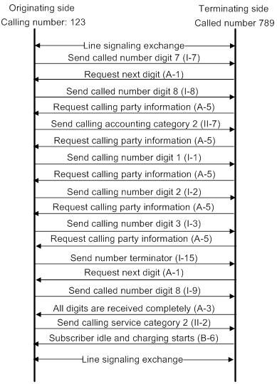
Configuring basic R2 signaling parameters
Configuring the R2 signaling standard
For the device to perform R2 signaling exchange with devices in a country or region, you need to specify the R2 signaling standard of that country or region.
To configure the R2 signaling standard:
|
Step |
Command |
Remarks |
|
1. Enter system view. |
system-view |
N/A |
|
2. Enter E1 or T1 interface view. |
controller { e1 | t1 } number |
N/A |
|
3. Create a timeslot set and enable R2 signaling for it. |
timeslot-set ts-set-number timeslot-list timeslots-list signal r2 |
By default, no timeslot sets exist. |
|
4. Enter R2 CAS view. |
cas ts-set-number |
N/A |
|
5. Specify the R2 signaling standard. |
mode zone-name [ default-standard ] |
By default, the ITU-T standard is adopted. |
Configuring the trunk direction and routing mode
|
Step |
Command |
Remarks |
|
1. Enter system view. |
system-view |
N/A |
|
2. Enter E1 or T1 interface view. |
controller { e1 | t1 } number |
N/A |
|
3. Create a timeslot set and enable R2 signaling for it. |
timeslot-set ts-set-number timeslot-list timeslots-list signal r2 |
By default, no timeslot sets exist. |
|
4. Enter R2 CAS view. |
cas ts-set-number |
N/A |
|
5. Configure the trunk direction. |
trunk-direction timeslots timeslots-list { dual | in | out } |
The default is dual. You cannot configure the in or out direction on both ends of a trunk. If you configure the dual direction on both ends, you need to configure different routing modes on the two ends by using the select-mode command to prevent timeslot contention. |
|
6. Specify a routing mode. |
select-mode { max | maxpoll | min | minpoll } |
The default is min. |
Configuring the terminating side to send busy tones to the originating side
|
Step |
Command |
Remarks |
|
1. Enter system view. |
system-view |
N/A |
|
2. Enter E1 or T1 interface view. |
controller { e1 | t1 } number |
N/A |
|
3. Create a timeslot set and enable R2 signaling for it. |
timeslot-set ts-set-number timeslot-list timeslots-list signal r2 |
By default, no timeslot sets exist. |
|
4. Enter R2 CAS view. |
cas ts-set-number |
N/A |
|
5. Configure the terminating side to send busy tones to the originating side. |
send ringbusy enable |
By default, the terminating side sends busy tones to the originating side. If you want the originating side to play busy tones, execute the undo send ringbusy enable command on the terminating side. |
|
6. Set the duration for playing busy tones. |
timer ringbusy time |
By default, the duration for playing busy tones is 30000 milliseconds. This command takes effect only after you configure the send ringbusy enable command. This command takes effect only on the terminating side. |
Configuring the duration for the terminating side to play ringback tones
|
Step |
Command |
Remarks |
|
1. Enter system view. |
system-view |
N/A |
|
2. Enter E1 or T1 interface view. |
controller { e1 | t1 } number |
N/A |
|
3. Create a timeslot set and enable R2 signaling for it. |
timeslot-set ts-set-number timeslot-list timeslots-list signal r2 |
By default, no timeslot sets exist. |
|
4. Enter R2 CAS view. |
cas ts-set-number |
N/A |
|
5. Set the duration for playing ringback tones. |
timer ringback time |
By default, the duration for playing ringback tones is 60000 milliseconds. |
Enabling DTMF to receive and send numbers
R2 signaling supports the following modes to send and receive numbers:
· MFC—The originating and terminating sides use interregister signaling to transmit and request number information, including the calling number, line information, and billing. In the exchange process, the terminating side sends responses to the originating side.
· DTMF—The originating side transmits the called number to the terminating side digit by digit. The terminating side does not send any responses.
Compared with the MFC mode, the DTMF mode has a faster connection speed but transmits a smaller amount of information.
To enable DTMF to receive and send numbers:
|
Step |
Command |
Remarks |
|
1. Enter system view. |
system-view |
N/A |
|
2. Enter E1 or T1 interface view. |
controller { e1 | t1 } number |
N/A |
|
3. Create a timeslot set and enable R2 signaling for it. |
timeslot-set ts-set-number timeslot-list timeslots-list signal r2 |
By default, no timeslot sets exist. |
|
4. Enter R2 CAS view. |
cas ts-set-number |
N/A |
|
5. Enable DTMF to receive and send numbers. |
dtmf enable |
By default, MFC mode is used. Configure the same mode on the originating and terminating devices. Otherwise, call establishment will fail. |
|
6. Set the delay before sending DTMF tones. |
timer dtmf-delay time |
The default is 50 milliseconds. This command takes effect only when the dtmf enable command has been configured. |
Configuring the connection mode
R2 signaling supports the following connection modes:
· terminal—After receiving the called number, the terminating side must wait for the state (busy or idle) of the called party before returning the corresponding interregister information to the originating side.
· segment—After receiving the called number, the terminating side directly returns the "called party idle" interregister signaling, without waiting for the real state of the terminating side. If the called party is busy, the terminating side plays busy tones to the originating side.
To configure the connection mode:
|
Step |
Command |
Remarks |
|
1. Enter system view. |
system-view |
N/A |
|
2. Enter E1 or T1 interface view. |
controller { e1 | t1 } number |
N/A |
|
3. Create a timeslot set and enable R2 signaling for it. |
timeslot-set ts-set-number timeslot-list timeslots-list signal r2 |
By default, no timeslot sets exist. |
|
4. Enter R2 CAS view. |
cas ts-set-number |
N/A |
|
5. Specify a connection mode. |
callmode { terminal | segment } |
By default, the terminal mode is used. |
Maintaining specified timeslots
|
Step |
Command |
Remarks |
|
1. Enter system view. |
system-view |
N/A |
|
2. Enter E1 or T1 interface view. |
controller { e1 | t1 } number |
N/A |
|
3. Create a timeslot set and enable R2 signaling for it. |
timeslot-set ts-set-number timeslot-list timeslots-list signal r2 |
By default, no timeslot sets exist. |
|
4. Enter R2 CAS view. |
cas ts-set-number |
N/A |
|
5. Maintain specified timeslots. |
ts { block | open | query | reset } timeslots timeslots-list |
N/A |
Configuring R2 digital line signaling
|
Step |
Command |
Remarks |
|
1. Enter system view. |
system-view |
N/A |
|
2. Enter E1 or T1 interface view. |
controller { e1 | t1 } number |
N/A |
|
3. Create a timeslot set and enable R2 signaling for it. |
timeslot-set ts-set-number timeslot-list timeslots-list signal r2 |
By default, no timeslot sets exist. |
|
4. Enter R2 CAS view. |
cas ts-set-number |
N/A |
|
5. Configure the originating side to require the terminating side to send answer signals. |
answer enable |
By default, the originating side requires the terminating side to send answer signals. |
|
6. Enable reanswer signal processing on the originating side. |
re-answer enable |
By default, reanswer signal processing is disabled on the originating side. |
|
7. Configure the terminating side to send clear-back signals when the originating side first disconnects the line. |
clear-forward-ack enable |
By default, the terminating side does not send clear-back signals when the originating side first disconnects the line. |
|
8. Enable metering signal processing. |
metering enable |
By default, metering signal processing is disabled. |
|
9. Configure the originating side to require the terminating side to send seizure acknowledgment signals. |
seizure-ack enable |
By default, the originating side requires the terminating side to send seizure acknowledgment signals. |
|
10. Configure the ABCD bit pattern for line signals. |
dl-bits { answer | blocking | clear-back | clear-forward | idle | release-guard | seizing | seizing-ack } { receive | transmit } ABCD |
The defaults are the values of the ITU-T standard. For the default values, see this command in Voice Command Reference. |
|
11. Configure the C and D signal bits. |
renew ABCD |
The default depends on the R2 signaling standard (configured by using the mode command). |
|
12. Configure line signal inversion mode. |
reverse ABCD |
The default is 0000, that is, line signal inversion is disabled. |
|
13. Set the timeout time of line signals. |
timer dl { answer | clear-back | clear-forward | | re-answer | release-guard | seizing } time |
By default, the timeout time is: · 60000 milliseconds for answer signals. · 10000 milliseconds for clear-back, clear-forward, and release-guard signals. · 1000 milliseconds for seizing and reanswer signals. |
Configuring R2 interregister signaling
|
Step |
Command |
Remarks |
|
1. Enter system view. |
system-view |
N/A |
|
2. Enter E1 or T1 interface view. |
controller { e1 | t1 } number |
N/A |
|
3. Create a timeslot set and enable R2 signaling for it. |
timeslot-set ts-set-number timeslot-list timeslots-list signal r2 |
By default, no timeslot sets exist. |
|
4. Enter R2 CAS view. |
cas ts-set-number |
N/A |
|
5. Configure the terminating side to request calling party information (calling category and calling number) from the originating side. |
ani { all | ka } |
By default, the terminating side does not request calling party information. |
|
6. Set the range for the number of calling number digits to be collected. |
ani-collected min min-value max max-value |
By default, no restriction is placed on the number of calling number digits to be collected. |
|
7. Configure the number of dialed digits that the terminating side collects before requesting calling party information. |
ani-digit number |
The default is 1. |
|
8. Set the interdigit timeout time in interregister signaling. |
ani-timeout timer-length |
By default, the interdigit timeout time in interregister signaling is 3 seconds. |
|
9. Use Group B signals to complete interregister signaling exchange. |
group-b enable |
By default, Group B signals are used. |
|
10. Configure the originating side to send a number terminator to the terminating side after sending the called number. |
final-callednum enable |
By default, the originating side does not send a number terminator to the terminating side after sending the called number. |
|
11. Configure a signal code for a special character. |
special-character character number |
By default, no signal code is configured for a special character. To configure signal codes for more special characters, repeat this command. |
|
12. Set interregister signal values. |
register-value { billingcategory | callcreate-in-groupa | callingcategory | congestion | demand-refused | digit-end | null-number | req-billingcategory | req-callednum-and-switchgroupa | req-callingcategory | req-currentcallednum-in-groupc | req-currentdigit | req-firstcallednum-in-groupc | req-firstcallingnum | req-firstdigit | req-lastfirstdigit | req-lastseconddigit | req-lastthirddigit | req-nextcallednum | req-nextcallingnum | req-switch-groupb | subscriber-abnormal |subscriber-busy | subscriber-charge |subscriber-idle } value |
The defaults depend on the R2 signaling standard (configured by using the mode command). |
|
13. Set the duration of register pulse signals. |
timer register-pulse time |
The default is 150 milliseconds. |
|
14. Set the maximum time to wait for a Group B signal. |
timer group-b time |
The default is 30000 milliseconds. |
Configuring the ISDN protocol
To use an E1 interface as an ISDN PRI, you need to create a PRI set by bundling timeslots other than timeslots 0 and 16. Timeslot 0 is used to transmit synchronization information, and timeslot 16 is used as the D channel for signaling transmission. For each PRI set, the system generates a serial interface and a logical digital voice interface. The serial interface is named serial interface-number:15, where interface-number is the number of the E1 interface. The serial interface has the same logical characteristics as synchronous serial interfaces and can be configured with ISDN settings.
A T1 interface is used in the same way as an E1 interface, except that it has 24 timeslots and timeslot 24 is used as the D channel for signaling transmission.
For more information about the ISDN protocol, see Layer 2—WAN Configuration Guide.
To configure the ISDN protocol:
|
Step |
Command |
|
1. Enter system view. |
system-view |
|
2. Enter E1 or T1 interface view. |
controller { e1 | t1 } number |
|
3. Bundle timeslots into a PRI set. |
pri-set [ timeslots-list range ] |
Binding a digital voice interface to a POTS entity
|
Step |
Command |
Remarks |
|
1. Enter system view. |
system-view |
N/A |
|
2. Enter voice view. |
voice-setup |
N/A |
|
3. Enter voice dial program view. |
dial-program |
N/A |
|
4. Create a POTS entity and enter POTS entity view. |
entity entity-number pots |
N/A |
|
5. Bind a digital voice interface to the POTS entity. |
·
For E1 and T1 interfaces: ·
For BSV interfaces: |
By default, no digital voice interface is bound to the POTS entity. |
Configuring reverse charging
This feature enables the router to identify a reverse-charge call by comparing the called number of an incoming call with a prefix. If the called number matches the prefix, the router interacts with the PBX device to charge the called party.
To configure reverse charging:
|
Command |
Remarks |
|
|
1. Enter system view. |
system-view |
N/A |
|
2. Enter digital voice interface view. |
subscriber-line line-number:{ ts-set-number | 15 | 23 } |
N/A |
|
3. Configure a prefix for reverse charging. |
reverse-charge prefix string |
By default, no prefix for reverse charging is configured. |
Enabling the router to treat DISCONNECT messages with PI 8 as standard DISCONNECT messages
When the router receives a standard DISCONNECT message, it brings down the user-side B-channel, sends a RELEASE message, and disconnects the call. When it receives a DISCONNECT message with Progress Indicator (PI) 8, it brings up the B-channel to receive in-band information. The device does not disconnect the call or release the B-channel resource until it receives a standard DISCONNECT messages.
To avoid unnecessarily occupying the B-channel resource, enable the device to treat DISCONNECT messages with PI 8 as standard DISCONNECT message.
To enable the router to treat DISCONNECT messages with PI 8 as standard DISCONNECT messages:
|
Step |
Command |
Remarks |
|
1. Enter system view. |
system-view |
N/A |
|
2. Enter voice view. |
voice-setup |
N/A |
|
3. Enable the router to treat DISCONNECT messages with PI 8 as standard DISCONNECT messages. |
By default, the router does not disconnect a call when it receives a DISCONNECT message with PI 8. |
Adjusting parameters for digital voice interfaces
All configuration tasks in this section are optional.
Adjusting gains
You can adjust gains to control the amount of volume in the input or output direction.
|
|
IMPORTANT: To avoid call failures, adjust gains only if necessary and do it under the guidance of technical engineers. |
To adjust gains:
|
Step |
Command |
Remarks |
|
1. Enter system view. |
system-view |
N/A |
|
2. Enter digital voice interface view. |
N/A |
|
|
3. Set the input gain. |
receive gain value |
The default is 0 dB. |
|
4. Set the output gain. |
transmit gain value |
The default is 0 dB. |
Enabling the comfortable noise feature
You can enable this feature to generate comfortable background noise to replace the silent gaps during a conversation.
To enable the comfortable noise feature:
|
Step |
Command |
Remarks |
|
1. Enter system view. |
system-view |
N/A |
|
2. Enter digital voice interface view. |
N/A |
|
|
3. Enable the comfortable noise feature. |
cng-on |
By default, this feature is enabled. |
Configuring echo cancellation
For more information about echo and echo cancellation, see "Configuring echo cancellation."
Configuring the echo cancellation feature
|
Step |
Command |
Remarks |
|
1. Enter system view. |
system-view |
N/A |
|
2. Enter digital voice interface view. |
subscriber-line line-number:{ ts-set-number | 15 | 23 } |
N/A |
|
3. Enable the echo cancellation feature. |
echo-canceler enable |
By default, this feature is enabled. |
|
4. Set the echo cancellation delay. |
echo-canceler delay milliseconds |
The default is 0 milliseconds. |
|
5. Set the echo cancellation coverage. |
echo-canceler tail-length milliseconds |
The default is 128 milliseconds. |
Adjusting echo cancellation parameters
Table 8 describes how to adjust echo cancellation parameters for different symptoms.
Table 8 Adjusting echo cancellation parameters
|
Symptom |
Parameters adjusted |
|
A user hears echoes or loud background noises from the peer when speaking. |
Speed up the convergence of comfortable noise amplitudes. |
|
There are loud environment noises. |
Increase the maximum amplitude of comfortable noises. |
|
A user hears echoes when speaking. |
Enlarge the mixture proportion control factor of comfortable noises. |
|
There are echoes when both parties speak at the same time. |
Enlarge the two-way judgment threshold. |
To adjust echo cancellation parameters:
|
Step |
Command |
Remarks |
|
1. Enter system view. |
system-view |
N/A |
|
2. Enter voice view. |
voice-setup |
N/A |
|
3. Adjust echo cancellation parameters. |
echo-canceler { convergence-rate value | max-amplitude value | mix-proportion-ratio value | talk-threshold value } |
By default: · The convergence rate of comfort noise amplitude is 0. · The maximum amplitude of comfort noise is 256. · The comfort noise mixture proportion control factor is 100. · The two-way judgment threshold is 1. These parameters take effect only when the echo-canceler enable command is configured. |
Enabling the nonlinear feature of echo cancellation
After echo cancellation is enabled, nonlinear parts in the line can cause residual echo. The nonlinear feature (also called residual echo suppression) can remove the residual echo.
To enable the nonlinear feature of echo cancellation:
|
Step |
Command |
Remarks |
|
1. Enter system view. |
system-view |
N/A |
|
2. Enter digital voice interface view. |
subscriber-line line-number:{ ts-set-number | 15 | 23 } |
N/A |
|
3. Enable the nonlinear feature of echo cancellation. |
nlp-on |
By default, this feature is enabled. This command takes effect only when the echo-canceler enable command is configured. |
Displaying and maintaining digital voice interfaces
Execute display commands in any view.
|
Task |
Command |
|
Display digital voice interfaces (for E1 or T1 interfaces). |
display voice subscriber line line-number:{ ts-set-number | ts-set-number.sub-timeslot | 15 | 23 } |
|
Display digital voice interfaces (for BSV interfaces). |
display voice subscriber line { line-number | ts-set-number.subnumber } |
Digital voice interface configuration examples
This section provides configuration examples for digital voice interfaces.
R2 signaling configuration example
Network requirements
As shown in Figure 20, configure R2 signaling on the routers so the telephones can call each other.
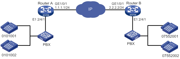
Configuration procedure
1. Configure Router A:
# Configure the IP address 1.1.1.1/24 for interface GigabitEthernet 1/0/1.
<RouterA> system-view
[RouterA] interface gigabitethernet 1/0/1
[RouterA-GigabitEthernet1/0/1] ip address 1.1.1.1 255.255.255.0
[RouterA-GigabitEthernet1/0/1] quit
# Create a timeslot set on interface E1 2/4/1.
[RouterA] controller e1 2/4/1
[RouterA-E1 2/4/1] timeslot-set 1 timeslot-list 1-31 signal r2
[RouterA-E1 2/4/1] quit
# Configure the local number 0101001 for POTS entity 1001, and bind the digital voice interface line 2/4/1:1 to the POTS entity.
[RouterA-voice-dial] entity 1001 pots
[RouterA-voice-dial-entity1001] match-template 0101001
[RouterA-voice-dial-entity1001] line 2/4/1:1
[RouterA-voice-dial-entity1001] send-number all
[RouterA-voice-dial-entity1001] quit
# Configure the local number 0101002 for POTS entity 1002, and bind the digital voice interface line 2/4/1:1 to the POTS entity.
[RouterA-voice-dial] entity 1002 pots
[RouterA-voice-dial-entity1002] match-template 0101002
[RouterA-voice-dial-entity1002] line 2/4/1:1
[RouterA-voice-dial-entity1002] send-number all
[RouterA-voice-dial-entity1002] quit
# Configure the called number template 0755…. for VoIP entity 0755, and configure the destination IP address as 2.2.2.2.
[RouterA-voice-dial] entity 0755 voip
[RouterA-voice-dial-entity755] match-template 0755....
[RouterA-voice-dial-entity755] address sip ip 2.2.2.2
2. Configure Router B:
# Configure the IP address 2.2.2.2/24 for interface GigabitEthernet 1/0/1.
<RouterB> system-view
[RouterB] interface gigabitethernet 1/0/1
[RouterB-GigabitEthernet1/0/1] ip address 2.2.2.2 255.255.255.0
[RouterB-GigabitEthernet1/0/1] quit
# Create a timeslot set on interface E1 2/4/1.
[RouterB] controller e1 2/4/1
[RouterB-E1 2/4/1] timeslot-set 1 timeslot-list 1-31 signal r2
[RouterB-E1 2/4/1] quit
# Configure the local number 07552001 for POTS entity 2001, and bind the digital voice interfaces line 2/4/1:1 to the POTS entity.
[RouterB] voice-setup
[RouterB-voice] dial-program
[RouterB-voice-dial] entity 2001 pots
[RouterB-voice-dial-entity2001] match-template 07552001
[RouterB-voice-dial-entity2001] line 2/4/1:1
[RouterB-voice-dial-entity2001] send-number all
[RouterB-voice-dial-entity2001] quit
# Configure the local number 07552002 for POTS entity 2002, and bind the digital voice interfaces line 2/4/1:1 to the POTS entity.
[RouterB-voice-dial] entity 2002 pots
[RouterB-voice-dial-entity2002] match-template 07552002
[RouterB-voice-dial-entity2002] line 2/4/1:1
[RouterB-voice-dial-entity2002] send-number all
[RouterB-voice-dial-entity2002] quit
# Configure the called number template 010…. for VoIP entity 010, and configure the destination IP address as 1.1.1.1.
[RouterB-voice-dial] entity 010 voip
[RouterB-voice-dial-entity10] match-template 010....
[RouterB-voice-dial-entity10] address ip 1.1.1.1
Verifying the configuration
# Place a call from a telephone attached to Router A to a telephone attached to Router B to verify that the telephones can call each other through R2 signaling.
# Use the display voice subscriber-line command to display information about digital voice interfaces. (Details not shown.)
E1 DSS1 signaling configuration example
Network requirements
As shown in Figure 21, the routers connect to the PBXs through E1 interfaces.
Configure DSS1 signaling on the routers so the telephones can call each other.
Configuration procedure
1. Configure Router A:
# Configure the IP address 1.1.1.1/24 for interface GigabitEthernet 1/0/1.
<RouterA> system-view
[RouterA] interface gigabitethernet 1/0/1
[RouterA-GigabitEthernet1/0/1] ip address 1.1.1.1 255.255.255.0
[RouterA-GigabitEthernet1/0/1] quit
# Bundle the timeslots on interface E1 2/4/1 into a PRI set.
[RouterA] controller e1 2/4/1
[RouterA-E1 2/4/1] pri-set
[RouterA-E1 2/4/1] quit
# Configure the local number 0101001 for POTS entity 1001, and bind the digital voice interfaces line 2/4/1:15 to the POTS entity.
[RouterA] voice-setup
[RouterA-voice] dial-program
[RouterA-voice-dial] entity 1001 pots
[RouterA-voice-dial-entity1001] match-template 0101001
[RouterA-voice-dial-entity1001] line 2/4/1:15
[RouterA-voice-dial-entity1001] send-number all
[RouterA-voice-dial-entity1001] quit
# Configure the local number 0101002 for POTS entity 1002, and bind the digital voice interfaces line 2/4/1:15 to the POTS entity.
[RouterA-voice-dial] entity 1002 pots
[RouterA-voice-dial-entity1002] match-template 0101002
[RouterA-voice-dial-entity1002] line 2/4/1:15
[RouterA-voice-dial-entity1002] send-number all
[RouterA-voice-dial-entity1002] quit
# Configure the called number template 0755…. for VoIP entity 0755, and configure the destination IP address as 2.2.2.2.
[RouterA-voice-dial] entity 0755 voip
[RouterA-voice-dial-entity755] match-template 0755....
[RouterA-voice-dial-entity755] address ip 2.2.2.2
2. Configure Router B:
# Configure the IP address 2.2.2.2/24 for interface GigabitEthernet 1/0/1.
<RouterB> system-view
[RouterB] interface gigabitethernet 1/0/1
[RouterB-GigabitEthernet1/0/1] ip address 2.2.2.2 255.255.255.0
[RouterB-GigabitEthernet1/0/1] quit
# Bundle the timeslots on interface E1 2/4/1 into a PRI set.
[RouterB] controller e1 2/4/1
[RouterB-E1 2/4/1] pri-set
[RouterB-E1 2/4/1] quit
# Configure the local number 07552001 for POTS entity 2001, and bind the digital voice interfaces line 2/4/1:15 to the POTS entity.
[RouterB] voice-setup
[RouterB-voice] dial-program
[RouterB-voice-dial] entity 2001 pots
[RouterB-voice-dial-entity2001] match-template 07552001
[RouterB-voice-dial-entity2001] line 2/4/1:15
[RouterB-voice-dial-entity2001] send-number all
[RouterB-voice-dial-entity2001] quit
# Configure the local number 07552002 for POTS entity 2002, and bind the digital voice interfaces line 2/4/1:15 to the POTS entity.
[RouterB-voice-dial] entity 2002 pots
[RouterB-voice-dial-entity2002] match-template 07552002
[RouterB-voice-dial-entity2002] line 2/4/1:15
[RouterB-voice-dial-entity2002] send-number all
[RouterB-voice-dial-entity2002] quit
# Configure the called number template 010…. for VoIP entity 010, and configure the destination IP address as 1.1.1.1.
[RouterB-voice-dial] entity 010 voip
[RouterB-voice-dial-entity10] match-template 010....
[RouterB-voice-dial-entity10] address ip 1.1.1.1
Verifying the configuration
# Place a call from a telephone attached to Router A to a telephone attached to Router B to verify that the telephones can call each other through DSS1 signaling.
# Use the display voice subscriber-line command to display information about digital voice interfaces. (Details not shown.)
BSV DSS1 signaling configuration example
Network requirements
As shown in Figure 22, the routers connect to the PBXs through BSV interfaces.
Configure DSS1 signaling on the routers so the telephones can call each other.

Configuration procedure
1. Configure Router A:
# Configure the IP address 1.1.1.1/24 for interface GigabitEthernet 1/0/1.
<RouterA> system-view
[RouterA] interface gigabitethernet 1/0/1
[RouterA-GigabitEthernet1/0/1] ip address 1.1.1.1 255.255.255.0
[RouterA-GigabitEthernet1/0/1] quit
# Configure the local number 0101001 for POTS entity 1001, and bind the digital voice interfaces line 2/5/1 to the POTS entity.
[RouterA] voice-setup
[RouterA-voice] dial-program
[RouterA-voice-dial] entity 1001 pots
[RouterA-voice-dial-entity1001] match-template 0101001
[RouterA-voice-dial-entity1001] line 2/5/1
[RouterA-voice-dial-entity1001] send-number all
[RouterA-voice-dial-entity1001] quit
# Configure the local number 0101002 for POTS entity 1002, and bind the digital voice interfaces line 2/5/1 to the POTS entity.
[RouterA-voice-dial] entity 1002 pots
[RouterA-voice-dial-entity1002] match-template 0101002
[RouterA-voice-dial-entity1002] line 2/5/1
[RouterA-voice-dial-entity1002] send-number all
[RouterA-voice-dial-entity1002] quit
# Configure the called number template 0755…. for VoIP entity 0755, and configure the destination IP address as 2.2.2.2.
[RouterA-voice-dial] entity 0755 voip
[RouterA-voice-dial-entity755] match-template 0755....
[RouterA-voice-dial-entity755] address sip ip 2.2.2.2
2. Configure Router B:
# Configure the IP address 2.2.2.2/24 for interface GigabitEthernet 1/0/1.
<RouterB> system-view
[RouterB] interface gigabitethernet 1/0/1
[RouterB-GigabitEthernet1/0/1] ip address 2.2.2.2 255.255.255.0
[RouterB-GigabitEthernet1/0/1] quit
# Configure the local number 07552001 for POTS entity 2001, and bind the digital voice interfaces line 2/5/1 to the POTS entity.
[RouterB] voice-setup
[RouterB-voice] dial-program
[RouterB-voice-dial] entity 2001 pots
[RouterB-voice-dial-entity2001] match-template 07552001
[RouterB-voice-dial-entity2001] line 2/5/1
[RouterB-voice-dial-entity2001] send-number all
[RouterB-voice-dial-entity2001] quit
# Configure the local number 07552002 for POTS entity 2002, and bind the digital voice interfaces line 2/5/1 to the POTS entity.
[RouterB-voice-dial] entity 2002 pots
[RouterB-voice-dial-entity2002] match-template 07552002
[RouterB-voice-dial-entity2002] line 2/5/1
[RouterB-voice-dial-entity2002] send-number all
[RouterB-voice-dial-entity2002] quit
# Configure the called number template 010…. for VoIP entity 010, and configure the destination IP address as 1.1.1.1.
[RouterB-voice-dial] entity 010 voip
[RouterB-voice-dial-entity10] match-template 010....
[RouterB-voice-dial-entity10] address ip 1.1.1.1
Verifying the configuration
# Place a call from a telephone attached to Router A to a telephone attached to Router B to verify that the telephones can call each other through DSS1 signaling.
# Use the display voice subscriber-line command to display information about digital voice interfaces. (Details not shown.)
Configuring voice entities
Overview
Based on the types of connected devices, voice entities include the following types:
· POTS entity—A local POTS entity connects to a local telephone and maintains local number information. A trunk POTS entity connects to the PSTN and maintains call destination information.
· VoIP entity—Connects to the IP side and uses SIP to make VoIP calls. VoIP entities include the following categories:
? Dynamic and static VoIP entities.
? Incoming and outgoing VoIP entities.
A static incoming VoIP entity maintains the called information such as called number and call destination. Other types of VoIP entities are used in SRST. For more information, see "Configuring SRST."
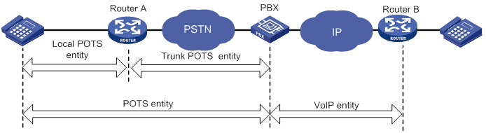
· IVR entity—Sets a customizable IVR system. For more information about IVR entities, see "Configuring customizable IVR."
Based on the directions of matching calls, voice entities include the following types:
· Incoming voice entity—Matches incoming calls. The device selects an incoming voice entity for an incoming call based on the calling number, the called number, or the PSTN interface. Incoming voice entities are used in the call pickup service and SIP register authentication.
· Outgoing voice entity—Matches outgoing calls. The device selects an outgoing voice entity for an outgoing call based on the called number. Outgoing voice entities are used to route calls to call destinations.
Feature and hardware compatibility
|
Hardware |
Voice entity compatibility |
|
MSR810/810-W/810-W-DB/810-LM/810-W-LM/810-10-PoE/810-LM-HK/810-W-LM-HK/810-LMS/810-LUS |
No |
|
MSR2600-6-X1/2600-10-X1 |
Yes |
|
MSR 2630 |
Yes |
|
MSR3600-28/3600-51 |
Yes |
|
MSR3600-28-SI/3600-51-SI |
No |
|
MSR3610-X1/3610-X1-DP/3610-X1-DC/3610-X1-DP-DC |
Yes |
|
MSR 3610/3620/3620-DP/3640/3660 |
Yes |
|
MSR5620/5660/5680 |
Yes (not supported on the router installed with an SPU600-X1 card.) |
|
Hardware |
Voice entity compatibility |
|
MSR810-LM-GL |
No |
|
MSR810-W-LM-GL |
No |
|
MSR830-6EI-GL |
No |
|
MSR830-10EI-GL |
No |
|
MSR830-6HI-GL |
No |
|
MSR830-10HI-GL |
No |
|
MSR2600-6-X1-GL |
Yes |
|
MSR3600-28-SI-GL |
No |
Configuration task list
|
Tasks at a glance |
|
Perform at least one of the following tasks: |
|
(Optional.) Setting the RTP timeout period |
|
(Optional.) Enabling SIP logging |
|
(Optional.) Setting the maximum duration of DSP-buffered data |
Configuring a POTS entity
This section covers the procedures for creating and configuring a POTS entity.
Configuration task list
|
Tasks at a glance |
|
(Required.) Creating a POTS entity and configuring basic parameters |
|
(Optional.) Configuring codecs for a POTS entity |
|
(Optional.) Configuring a POTS entity to register with the registrar |
|
(Optional.) Configuring DTMF for a POTS entity |
|
(Optional.) Setting a DSCP value for a POTS entity |
|
(Optional.) Configuring playout delay for a POTS entity |
|
(Optional.) Enabling VAD for a POTS entity |
|
(Optional.) Configuring the POTS entity to play ringback tones |
|
(Optional.) Configuring options related to dial program |
Creating a POTS entity and configuring basic parameters
Upon receiving a call, the router selects an incoming POTS entity by comparing the call information with POTS entity attributes in the following order:
1. Called number with the called number string configured by the incoming called-number command.
2. Calling number with the calling number string configured by the answer-address command.
3. Calling number with the number template configured by the match-template command.
Once the call matches a POTS entity, the router stops matching and routes the call based on the attributes of the matching POTS entity.
To create a POTS entity and configure basic parameters:
|
Step |
Command |
Remarks |
|
1. Enter system view. |
system-view |
N/A |
|
2. Enter voice view. |
voice-setup |
N/A |
|
3. Enter dial program view. |
dial-program |
N/A |
|
4. Create a POTS entity and enter its view. |
entity entity-number pots |
By default, no POTS entities exist. |
|
5. (Optional.) Configure a description for the POTS entity. |
description text |
By default, no description exists. |
|
6. Configure a number template for the POTS entity. |
match-template match-string |
By default, no number template exists. The POTS entity uses the number template to match phone numbers. For example, the match-template 20 command matches all numbers beginning with 20. |
|
7. Bind a voice interface to the POTS entity. |
line line-number |
By default, no voice interface is bound to a POTS entity. |
|
8. (Optional.) Configure a number string for the POTS entity to match incoming calls. |
·
(Method 1) Configure a called number string: ·
(Method 2) Configure a calling number
string: |
By default, no called number string or calling number string exists. |
|
9. Enable the POTS entity. |
undo shutdown |
By default, a POTS entity is enabled. |
Configuring codecs for a POTS entity
By default, a POTS entity has four codecs g729r8, g711alaw, g711ulaw, and g723r53 in descending order of priority.
You can use one of the following methods to configure codecs for a POTS entity:
· Method 1: Configure codecs for a POTS entity.
· Method 2: Create a codec template, assign priorities to codecs in the codec template, and bind the codec template to a POTS entity.
Two parties must have the same codecs to communicate with each other. You can use the display voice sip call command (see Voice Command Reference) to view the codec used by two parties.
To configure codecs for a POTS entity (method 1):
|
Step |
Command |
Remarks |
|
1. Enter system view. |
system-view |
N/A |
|
2. Enter voice view. |
voice-setup |
N/A |
|
3. Enter dial program view. |
dial-program |
N/A |
|
4. Enter POTS entity view. |
entity entity-number pots |
N/A |
|
5. Configure a codec for the POTS entity. |
codec { g711alaw | g711ulaw | g723r53 | g723r63 | g726r16 | g726r24 | g726r32 | g726r40 | g729a | g729br8 | g729r8 } [ bytes payload-size ] |
By default, no codec exists. |
To configure codecs for a POTS entity (method 2):
|
Step |
Command |
Remarks |
|
1. Enter system view. |
system-view |
N/A |
|
2. Enter voice view. |
voice-setup |
N/A |
|
3. Create a codec template and enter its view. |
voice class codec tag |
By default, no codec templates exist. |
|
4. Assign a priority to a codec in the codec template. |
codec preference priority { g711alaw | g711ulaw | g723r53 | g723r63 | g726r16 | g726r24 | g726r32 | g726r40 | g729a | g729br8 | g729r8 } [ bytes payload-size ] |
By default, no codecs exist in a codec template. Repeat this command to assign priorities to more codecs. |
|
5. Return to voice view. |
quit |
N/A |
|
6. Enter dial program view. |
dial-program |
N/A |
|
7. Enter POTS entity view. |
entity entity-number pots |
N/A |
|
8. Bind the codec template to the POTS entity. |
voice-class codec tag |
By default, the binding does not exist. |
Configuring a POTS entity to register with the registrar
|
Step |
Command |
Remarks |
|
1. Enter system view. |
system-view |
N/A |
|
2. Enter voice view. |
voice-setup |
N/A |
|
3. Enter dial program view. |
dial-program |
N/A |
|
4. Enter POTS entity view. |
entity entity-number pots |
N/A |
|
5. Configure the POTS entity to register with the registrar server. |
register number |
By default, a POTS entity initiates a registration to the registrar server after UA registration is configured. If you do not want to register a number or you want to deregister a number from the registrar, you can use the undo register number command. |
Configuring DTMF for a POTS entity
There are two ways to transmit DTMF tones: inband signaling and out-of-band signaling.
Inband signaling sends DTMF tones in RTP packets, and out-of-band signaling sends DTMF tones in SIP messages, or RFC 2883-compliant RTP messages (NTE mode).
To use NTE mode, configure the outband nte command and the same payload type value on the originating and terminating sides. Otherwise, the originating side might fail to transmit DTMF tones. For more information about out-of-band DTMF, see "Configuring SIP."
To configure DTMF for a POTS entity:
|
Step |
Command |
Remarks |
|
1. Enter system view. |
system-view |
N/A |
|
2. Enter voice view. |
voice-setup |
N/A |
|
3. Enter dial program view. |
dial-program |
N/A |
|
4. Enter POTS entity view. |
entity entity-number pots |
N/A |
|
5. Configure out-of-band DTMF. |
· (Method 1) Configure NTE mode: ? Enable NTE mode: ? Set the value of the payload type used by NTE: ·
(Method 2) Configure SIP mode: |
Use either method. By default, inband transmission is adopted, and the value of the payload type used by NTE is 101. When the device is connected to a device from another vendor, you cannot set the payload type field to any value forbidden by that device. Otherwise, an NTE negotiation failure might occur. |
Setting a DSCP value for a POTS entity
You can set a DSCP value for IP packets carrying media streams to provide differentiated voice services.
You can configure the ip qos dscp command both globally (in SIP view) and for a specific POTS entity (in POTS entity view). The configuration in POTS entity view takes precedence over the global configuration. A POTS entity uses the global configuration only when the ip qos dscp command is not configured in POTS entity view. For information about configuring a DSCP value in SIP view, see "Configuring SIP."
To set a DSCP value for a POTS entity:
|
Step |
Command |
Remarks |
|
1. Enter system view. |
system-view |
N/A |
|
2. Enter voice view. |
voice-setup |
N/A |
|
3. Enter dial program view. |
dial-program |
N/A |
|
4. Enter POTS entity view. |
entity entity-number pots |
N/A |
|
5. Set a DSCP value for IP packets carrying media streams. |
ip qos dscp { dscp-value | dscp-value-set } media |
The default value is ef (101110), the global default value. |
Configuring playout delay for a POTS entity
In an ideal voice network environment, the delay of each voice packet (time for each voice packet to travel from the sender to the receiver) is fixed. That is, the jitter is 0. In an actual voice network, the delay varies from packet to packet.
To smoothly play out voice packets received with different delay times, the receiver can buffer the voice packets for a period of time (playout delay time). By configuring playout delay, you can prevent delay variation (jitter) from affecting voice quality.
To configure playout delay for a POTS entity:
|
Step |
Command |
Remarks |
|
1. Enter system view. |
system-view |
N/A |
|
2. Enter voice view. |
voice-setup |
N/A |
|
3. Enter dial program view. |
dial-program |
N/A |
|
4. Enter POTS entity view. |
entity entity-number pots |
N/A |
|
5. Configure the playout delay mode for the POTS entity. |
playout-delay mode { adaptive | fixed } |
The default mode is fixed. |
|
6. Configure the playout delay time. |
playout-delay { initial milliseconds | maximum milliseconds | minimum milliseconds } |
By default: · The initial playout delay time is 30 milliseconds. · The maximum playout delay time is 160 milliseconds. · The minimum playout delay time is 10 milliseconds. |
Enabling VAD for a POTS entity
The voice activity detection (VAD) feature discriminates between silence and speech on a voice connection according to their energies. With VAD, a POTS entity does not generate traffic during periods of silence.
When you configure VAD for a POTS entity, follow these restrictions and guidelines:
· G.711 codec is supported only on the following interface modules:
? DSIC-4FXS1FXO-H3.
? HMIM-1VE1
? HMIM-1VT1
? HMIM-2VE1
? HMIM-2VT1.
? RT-SIC-1VE1T1.
? SIC-1BSV-H3.
? SIC-1VE1-H3.
? SIC-1VT1-H3.
? SIC-2BSV-H3.
? SIC-2FXS1FXO-H3.
· Make sure the DSP image on the device is a Microsoft-verified version. To set the DSP image type, use the dsp-image ms command.
· G.726 codec does not support VAD.
· G.729br8 codec always supports VAD.
To enable VAD for a POTS entity:
|
Step |
Command |
Remarks |
|
1. Enter system view. |
system-view |
N/A |
|
2. Enter voice view. |
voice-setup |
N/A |
|
3. Enter dial program view. |
dial-program |
N/A |
|
4. Enter POTS entity view. |
entity entity-number pots |
N/A |
|
5. Enable VAD for the POTS entity. |
vad-on [ g711 | g723r53 | g723r63 | g729a | g729r8 ] * |
By default, VAD is disabled for a POTS entity. |
Configuring the POTS entity to play ringback tones
If the terminating side of a call cannot play ringback tones, configure the POTS entity on the originating side to play ringback tones.
This feature does not take effect if the POTS entity is bound to an FXS or FXO interface.
To configure the POTS entity to play ringback tones:
|
Step |
Command |
Remarks |
|
1. Enter system view. |
system-view |
N/A |
|
2. Enter voice view. |
voice-setup |
N/A |
|
3. Enter dial program view. |
dial-program |
N/A |
|
4. Enter POTS entity view. |
entity entity-number pots |
N/A |
|
5. Configure the POTS entity to play ringback tones. |
send-ring |
By default, a POTS entity does not play ringback tones. |
Configuring options related to dial program
|
Step |
Command |
Remarks |
|
1. Enter system view. |
system-view |
N/A |
|
2. Enter voice view. |
voice-setup |
N/A |
|
3. Enter dial program view. |
dial-program |
N/A |
|
4. Enter POTS entity view. |
entity entity-number pots |
N/A |
|
5. Configure permitted calling numbers. |
caller-permit calling-string |
By default, a POTS entity permits all calling numbers. |
|
6. Configure the priority of the POTS entity. |
priority priority-order |
By default, the priority level is 0. The smaller the number, the higher the priority. |
|
7. Configure the maximum number of calls allowed by the POTS entity. |
max-conn max-number |
By default, the number of calls allowed by a POTS entity is not limited. |
|
8. Configure a dial prefix for the POTS entity |
dial-prefix string |
By default, no dial prefix exists. |
|
9. Bind a number substitution rule list to the POTS entity. |
substitute { called | calling } list-number |
By default, no number substitution rule list is bound to a POTS entity (no number substitution is performed). |
|
10. Bind a subscriber group to the POTS entity. |
caller-group { deny | permit } group-id |
By default, no subscriber group is bound to a POTS entity (any calling number is allowed to originate calls). |
|
11. Configure the number sending mode. |
send-number { digit-number | all | truncate } |
By default, the truncate mode is used. |
For more information about the above commands, see "Configuring dial programs."
Configuring a VoIP entity
This section covers the procedures for creating and configuring a VoIP entity.
Configuration task list
|
Tasks at a glance |
|
(Required.) Creating a VoIP entity and configuring basic parameters |
|
(Optional.) Configuring codecs for a VoIP entity |
|
(Optional.) Configuring DTMF for a VoIP entity |
|
(Optional.) Enabling VAD for a VoIP entity |
|
(Optional.) Setting a DSCP value for a VoIP entity |
|
(Optional.) Configuring playout delay for a VoIP entity |
|
(Optional.) Configuring the VoIP entity to play ringback tones |
|
(Optional.) Configuring options related to dial program |
Creating a VoIP entity and configuring basic parameters
Upon receiving a call, the router selects an incoming VoIP entity by comparing the call information with VoIP entity attributes in the following order:
1. Called number with the called number string configured by the incoming called-number command.
2. Calling number with the calling number string configured by the answer-address command.
3. Calling number with the number template configured by the match-template command.
Once the call matches a VoIP entity, the router stops matching and routes the call based on the attributes of the matching VoIP entity.
To create a VoIP entity and configure basic parameters:
|
Step |
Command |
Remarks |
|
1. Enter system view. |
system-view |
N/A |
|
2. Enter voice view. |
voice-setup |
N/A |
|
3. Enter dial program view. |
dial-program |
N/A |
|
4. Create a VoIP entity and enter its view. |
entity entity-number voip |
By default, no VoIP entities exist. |
|
5. (Optional.) Configure a description for the VoIP entity. |
description text |
By default, no description exists. |
|
6. Configure a number template for the VoIP entity. |
match-template match-string |
By default, no number template exists. The VoIP entity uses the number template to match phone numbers. For example, the match-template 20 command matches all numbers beginning with 20. |
|
7. Configure the destination IP address. |
address sip ip ip-address [ port port-number ] |
By default, no destination IP address exists. For more information about this command, see Voice Command Reference. |
|
8. (Optional.) Configure number string for the VoIP entity to match incoming calls. |
·
(Method 1) Configure a called number string: ·
(Method 2) Configure a calling number
string: |
By default, no called number string or calling number string exists. |
|
9. Enable the VoIP entity. |
undo shutdown |
By default, a VoIP entity is enabled. |
Configuring codecs for a VoIP entity
By default, a VoIP entity has four codecs g729r8, g711alaw, g711ulaw, and g723r53 in descending order of priority.
You can use one of the following methods to configure codecs for a VoIP entity:
· Method 1: Configure codecs directly for a VoIP entity.
· Method 2: Create a codec template, assign priorities to codecs in the codec template, and bind the codec template to a VoIP entity.
Two parties must have the same codecs to communicate with each other. You can use the display voice sip call command (see Voice Command Reference) to view the codec used by two parties.
To configure codecs for a VoIP entity (method 1):
|
Step |
Command |
Remarks |
|
1. Enter system view. |
system-view |
N/A |
|
2. Enter voice view. |
voice-setup |
N/A |
|
3. Enter dial program view. |
dial-program |
N/A |
|
4. Enter VoIP entity view. |
entity entity-number voip |
N/A |
|
5. Specify a codec for the VoIP entity. |
codec { g711alaw | g711ulaw | g723r53 | g723r63 | g726r16 | g726r24 | g726r32 | g726r40 | g729a | g729br8 | g729r8 } [ bytes payload-size ] |
By default, no codec exists. |
To configure codecs for a VoIP entity (method 2):
|
Step |
Command |
Remarks |
|
1. Enter system view. |
system-view |
N/A |
|
2. Enter voice view. |
voice-setup |
N/A |
|
3. Create a codec template and enter its view. |
voice class codec tag |
By default, no codec templates exist. |
|
4. Assign a priority to a codec in the codec template. |
codec preference priority { g711alaw | g711ulaw | g723r53 | g723r63 | g726r16 | g726r24 | g726r32 | g726r40 | g729a | g729br8 | g729r8 } [ bytes payload-size ] |
By default, no codecs exist in a codec template. Repeat this command to assign priorities to more codecs. |
|
5. Return to voice view. |
quit |
N/A |
|
6. Enter dial program view. |
dial-program |
N/A |
|
7. Enter VoIP entity view. |
entity entity-number voip |
N/A |
|
8. Bind the codec template to the VoIP entity. |
voice-class codec tag |
By default, no codec template is bound to a VoIP entity. |
Configuring DTMF for a VoIP entity
There are two ways to transmit DTMF tones: inband signaling and out-of-band signaling.
Inband signaling sends DTMF tones in RTP packets. Out-of-band signaling sends DTMF tones in SIP messages, or RFC 2883-compliant RTP packets (NTE mode).
To use the NTE mode, configure command outband nte and the same payload type value on both the originating and terminating sides. Otherwise, the originating side might fail to transmit DTMF tones. For more information about out-of-band DTMF, see "Configuring SIP."
To configure DTMF for a VoIP entity:
|
Step |
Command |
Remarks |
|
1. Enter system view. |
system-view |
N/A |
|
2. Enter voice view. |
voice-setup |
N/A |
|
3. Enter dial program view. |
dial-program |
N/A |
|
4. Enter VoIP entity view. |
entity entity-number voip |
N/A |
|
5. Configure out-of-band DTMF signaling. |
· (Method 1) Configure NTE mode: a. Enable NTE mode: b. Configure the value of the NTE payload type: ·
(Method 2) Configure SIP mode: |
Use either method. By default, inband DTMF signaling is used, and the value of the NTE payload type is 101. When the device is connected to a device from another vendor, you cannot set the payload type field to any value forbidden by that device. Otherwise, an NTE negotiation failure might occur. |
Enabling VAD for a VoIP entity
The voice activity detection (VAD) feature discriminates between silence and speech on a voice connection according to their energies. With VAD, a POTS entity does not generate traffic during periods of silence in an active voice connection.
When you configure VAD for a VoIP entity, follow these restrictions and guidelines:
· G.711 codec is supported only on the following interface modules:
? DSIC-4FXS1FXO-H3.
? HMIM-1VE1
? HMIM-1VT1
? HMIM-2VE1
? HMIM-2VT1.
? RT-SIC-1VE1T1.
? SIC-1BSV-H3.
? SIC-1VE1-H3.
? SIC-1VT1-H3.
? SIC-2BSV-H3.
? SIC-2FXS1FXO-H3.
· Make sure the DSP image on the device is a Microsoft-verified version. To set the DSP image type, use the dsp-image ms command.
· G.726 codec does not support VAD.
· G.729br8 codec always supports VAD.
To enable VAD for a VoIP entity:
|
Step |
Command |
Remarks |
|
1. Enter system view. |
system-view |
N/A |
|
2. Enter voice view. |
voice-setup |
N/A |
|
3. Enter dial program view. |
dial-program |
N/A |
|
4. Enter VoIP entity view. |
entity entity-number voip |
N/A |
|
5. Enable VAD for a VoIP entity. |
vad-on [ g711 | g723r53 | g723r63 | g729a | g729r8 ] * |
By default, VAD is disabled for a VoIP entity. |
Setting a DSCP value for a VoIP entity
You can set a DSCP value for IP packets carrying media streams to provide differentiated voice services.
You can configure the ip qos dscp command both globally (in SIP view) and for a specific VoIP entity (in VoIP entity view).The configuration in VoIP entity view takes precedence over the global configuration. A VoIP entity uses the global configuration only when the ip qos dscp command is not configured in VoIP entity view. For information about configuring a DSCP value in SIP view, see "Configuring SIP."
To set a DSCP value for a VoIP entity:
|
Step |
Command |
Remarks |
|
1. Enter system view. |
system-view |
N/A |
|
2. Enter voice view. |
voice-setup |
N/A |
|
3. Enter dial program view. |
dial-program |
N/A |
|
4. Enter VoIP entity view. |
entity entity-number voip |
N/A |
|
5. Set a DSCP value for IP packets carrying media streams. |
ip qos dscp { dscp-value | dscp-value-set } media |
The default value is ef (101110), the global default value. |
Configuring playout delay for a VoIP entity
In an ideal voice network environment, the delay of each voice packet (time for each voice packet to transmit from the sender to the receiver) is fixed. That is, the jitter is 0. In an actual voice network, the delay varies from packet to packet.
To smoothly play out voice packets received with different delay times, the receiver can buffer the voice packets for a period of time (playout delay time). By configuring playout delay, you can prevent delay variation (jitter) from affecting voice quality.
To configure playout delay for a VoIP entity:
|
Step |
Command |
Remarks |
|
1. Enter system view. |
system-view |
N/A |
|
2. Enter voice view. |
voice-setup |
N/A |
|
3. Enter dial program view. |
dial-program |
N/A |
|
4. Enter VoIP entity view. |
entity entity-number voip |
N/A |
|
5. Configure the playout delay mode for the VoIP entity. |
playout-delay mode { adaptive | fixed } |
The default mode is fixed. |
|
6. Configure the playout delay time. |
playout-delay { initial milliseconds | maximum milliseconds | minimum milliseconds } |
By default: · The initial playout delay time is 30 milliseconds. · The maximum playout delay time is 160 milliseconds. · The minimum playout delay time is 10 milliseconds. |
Configuring the VoIP entity to play ringback tones
If the terminating side of a call cannot play ringback tones, configure the VoIP entity on the originating side to play ringback tones.
To configure the VoIP entity to play ringback tones:
|
Step |
Command |
Remarks |
|
1. Enter system view. |
system-view |
N/A |
|
2. Enter voice view. |
voice-setup |
N/A |
|
3. Enter dial program view. |
dial-program |
N/A |
|
4. Enter VoIP entity view. |
entity entity-number voip |
N/A |
|
5. Configure the VoIP entity to play ringback tones. |
send-ring |
By default, a VoIP entity does not play ringback tones. |
Configuring options related to dial program
|
Step |
Command |
Remarks |
|
1. Enter system view. |
system-view |
N/A |
|
2. Enter voice view. |
voice-setup |
N/A |
|
3. Enter dial program view. |
dial-program |
N/A |
|
4. Enter VoIP entity view. |
entity entity-number voip |
N/A |
|
5. Configure the permitted calling numbers. |
caller-permit calling-string |
By default, a voice entity permits all calling numbers. |
|
6. Configure the maximum number of calls allowed by the VoIP entity. |
max-conn max-number |
By default, the number of calls allowed by a VoIP entity is not limited. |
|
7. Configure the priority of the VoIP entity. |
priority priority-order |
By default, the priority level is 0. The smaller the number, the higher the priority. |
|
8. Bind a number substitution rule list to the VoIP entity. |
substitute { called | calling } list-number |
By default, no number substitution rule list is bound to a VoIP entity. |
|
9. Bind a subscriber group to the VoIP entity. |
caller-group { deny | permit } group-id |
By default, no subscriber group is bound to a VoIP entity. |
For more information about the above commands, see "Configuring dial programs."
Configuring an IVR entity
This section covers the procedures for creating and configuring an IVR entity.
Configuration task list
|
Tasks at a glance |
|
(Required.) Creating an IVR entity and configuring basic parameters |
|
(Optional.) Configuring codecs for an IVR entity |
|
(Optional.) Configuring an IVR entity to register with the registrar |
|
(Optional.) Configuring DTMF for an IVR entity |
|
(Optional.) Setting a DSCP value for an IVR entity |
|
(Optional.) Enabling VAD for an IVR entity |
|
(Optional.) Configuring options related to dial program |
Creating an IVR entity and configuring basic parameters
|
Step |
Command |
Remarks |
|
1. Enter system view. |
system-view |
N/A |
|
2. Enter voice view. |
voice-setup |
N/A |
|
3. Enter dial program view. |
dial-program |
N/A |
|
4. Create an IVR entity and enter its view. |
entity entity-number ivr |
By default, no IVR entities exist. |
|
5. (Optional.) Configure a description for the IVR entity. |
description text |
By default, no description exists. |
|
6. Configure a number template for the IVR entity. |
match-template match-string |
By default, no number template exists. The IVR entity uses the number template to match phone numbers. For example, the match-template 20 command matches all numbers beginning with 20. |
|
7. Configure a root node for the IVR entity. |
ivr-root node-id |
By default, no root node exists. For more information about this command, see Voice Command Reference. |
|
8. Enable the IVR entity. |
undo shutdown |
By default, an IVR entity is enabled. |
Configuring codecs for an IVR entity
By default, an IVR entity has four codecs g729r8, g711alaw, g711ulaw, and g723r53 in descending order of priority.
You can use one of the following methods to configure codecs for an IVR entity:
· Method 1: Configure codecs directly for an IVR entity.
· Method 2: Create a codec template, assign priorities to codecs in the codec template, and bind the codec template to an IVR entity.
Two parties must have the same codecs to communicate with each other. You can use the display voice sip call command (see Voice Command Reference) to view the codec used by two parties.
To configure codecs for an IVR entity (method 1):
|
Step |
Command |
Remarks |
|
1. Enter system view. |
system-view |
N/A |
|
2. Enter voice view. |
voice-setup |
N/A |
|
3. Enter dial program view. |
dial-program |
N/A |
|
4. Enter IVR entity view. |
entity entity-number ivr |
N/A |
|
5. Specify a codec for the IVR entity. |
codec { g711alaw | g711ulaw | g723r53 | g723r63 | g726r16 | g726r24 | g726r32 | g726r40 | g729a | g729br8 | g729r8 } [ bytes payload-size ] |
By default, no codec exists. |
To configure codecs for an IVR entity (method 2):
|
Step |
Command |
Remarks |
|
1. Enter system view. |
system-view |
N/A |
|
2. Enter voice view. |
voice-setup |
N/A |
|
3. Create a codec template and enter its view. |
voice class codec tag |
By default, no codec templates exist. |
|
4. Assign a priority to a codec in the codec template. |
codec preference priority { g711alaw | g711ulaw | g723r53 | g723r63 | g726r16 | g726r24 | g726r32 | g726r40 | g729a | g729br8 | g729r8 } [ bytes payload-size ] |
By default, no codecs exist in a codec template. Repeat this command to assign priorities to more codecs. |
|
5. Return to voice view. |
quit |
N/A |
|
6. Enter dial program view. |
dial-program |
N/A |
|
7. Enter IVR entity view. |
entity entity-number ivr |
N/A |
|
8. Bind the codec template to the IVR entity. |
voice-class codec tag |
By default, the binding does not exist. |
Configuring an IVR entity to register with the registrar
|
Step |
Command |
Remarks |
|
1. Enter system view. |
system-view |
N/A |
|
2. Enter voice view. |
voice-setup |
N/A |
|
3. Enter dial program view. |
dial-program |
N/A |
|
4. Enter IVR entity view. |
entity entity-number ivr |
N/A |
|
5. Configure the IVR entity to register with the registrar. |
By default, an IVR entity initiates a registration to the registrar after UA registration is configured. If you do not want to register a number or you want to deregister a number from the registrar, you can use the undo register number command. |
Configuring DTMF for an IVR entity
There are two ways to transmit DTMF tones: inband signaling and out-of-band signaling.
Inband signaling sends DTMF tones in RTP packets, and out-of-band signaling sends DTMF tones in SIP messages, or RFC 2883-compliant RTP packets (NTE mode).
To use the NTE mode, configure command outband nte and the same payload type value on both the originating and terminating sides. Otherwise, the originating side might fail to transmit DTMF tones.
To configure DTMF for an IVR entity:
|
Step |
Command |
Remarks |
|
1. Enter system view. |
system-view |
N/A |
|
2. Enter voice view. |
voice-setup |
N/A |
|
3. Enter dial program view. |
dial-program |
N/A |
|
4. Enter IVR entity view. |
entity entity-number ivr |
N/A |
|
5. Configure out-of-band DTMF by using NTE mode. |
·
Enable NTE mode: ·
Configure the value of the NTE payload type: |
By default, inband DTMF signaling is used, and the value of the NTE payload type is 101. When the device is connected to a device from another vendor, you cannot set the payload type field to any value forbidden by that device. Otherwise, an NTE negotiation failure might occur. |
Setting a DSCP value for an IVR entity
You can set a DSCP value for IP packets carrying media streams to provide differentiated voice services.
You can configure the ip qos dscp command both globally (in SIP view) and for a specific IVR entity (in IVR entity view).The configuration in IVR entity view takes precedence over the global configuration. An IVR entity uses the global configuration only when the ip qos dscp command is not configured in IVR entity view. For information about configuring a DSCP value in SIP view, see "Configuring SIP."
To set a DSCP value for an IVR entity:
|
Step |
Command |
Remarks |
|
1. Enter system view. |
system-view |
N/A |
|
2. Enter voice view. |
voice-setup |
N/A |
|
3. Enter dial program view. |
dial-program |
N/A |
|
4. Enter IVR entity view. |
entity entity-number ivr |
N/A |
|
5. Set a DSCP value for IP packets carrying media streams. |
ip qos dscp { dscp-value | dscp-value-set } media |
The default value is ef (101110), the global default value. |
Enabling VAD for an IVR entity
The voice activity detection (VAD) feature discriminates between silence and speech on a voice connection according to their energies. With VAD, an IVR entity does not generate traffic during periods of silence in an active voice connection.
When you configure VAD for an IVR entity, follow these restrictions and guidelines:
· G.711 codec is supported only on the following interface modules:
? DSIC-4FXS1FXO-H3.
? HMIM-1VE1
? HMIM-1VT1
? HMIM-2VE1
? HMIM-2VT1.
? RT-SIC-1VE1T1.
? SIC-1BSV-H3.
? SIC-1VE1-H3.
? SIC-1VT1-H3.
? SIC-2BSV-H3.
? SIC-2FXS1FXO-H3.
· Make sure the DSP image on the device is a Microsoft-verified version. To set the DSP image type, use the dsp-image ms command.
· G.726 codec does not support VAD.
· G.729br8 codec always supports VAD.
To enable VAD for an IVR entity:
|
Step |
Command |
Remarks |
|
1. Enter system view. |
system-view |
N/A |
|
2. Enter voice view. |
voice-setup |
N/A |
|
3. Enter dial program view. |
dial-program |
N/A |
|
4. Enter IVR entity view. |
entity entity-number ivr |
N/A |
|
5. Enable VAD for the IVR entity. |
vad-on [ g711 | g723r53 | g723r63 | g729a | g729r8 ] * |
By default, VAD is disabled for an IVR entity. |
Configuring options related to dial program
|
Step |
Command |
Remarks |
|
1. Enter system view. |
system-view |
N/A |
|
2. Enter voice view. |
voice-setup |
N/A |
|
3. Enter dial program view. |
dial-program |
N/A |
|
4. Enter IVR entity view. |
entity entity-number ivr |
N/A |
|
5. Configure the permitted calling numbers. |
caller-permit calling-string |
By default, an IVR entity permits all calling numbers. |
|
6. Configure the priority of the IVR entity. |
priority priority-order |
By default, the priority level is 0. The smaller the number, the higher the priority. |
|
7. Configure the maximum number of calls allowed by the IVR entity. |
max-conn max-number |
By default, the number of calls allowed by an IVR entity is not limited. |
|
8. Bind a number substitution rule list to the IVR entity. |
substitute { called | calling } list-number |
By default, no number substitution rule list is bound to an IVR entity. |
|
9. Bind a subscriber group to the IVR entity. |
caller-group { deny | permit } group-id |
By default, no subscriber group is bound to an IVR entity. |
For more information about the above commands, see "Configuring dial programs."
Setting the RTP timeout period
The device disconnects a call if it does not receive RTP traffic during the set timeout period.
To set the RTP timeout period:
|
Step |
Command |
Remarks |
|
1. Enter system view. |
system-view |
N/A |
|
2. Enter voice view. |
voice-setup |
N/A |
|
3. Set the RTP timeout period. |
rtp-detect timeout value |
By default, the RTP timeout period is 120 seconds. |
Enabling SIP logging
SIP logging enables the device to log SIP call events and send the log message to the information center. With the information center, you can set log message filtering and output rules, including output destinations. For more information about using the information center, see Network Management and Monitoring Configuration Guide.
To enable SIP logging:
|
Step |
Command |
Remarks |
|
1. Enter system view. |
system-view |
N/A |
|
2. Enter voice view. |
voice-setup |
N/A |
|
3. Enable SIP logging. |
sip log enable |
By default, SIP logging is disabled. |
Setting the maximum duration of DSP-buffered data
The following matrix shows the feature and hardware compatibility:
|
Hardware |
Feature compatibility |
|
MSR810/810-W/810-W-DB/810-LM/810-W-LM/810-10-PoE/810-LM-HK/810-W-LM-HK/810-LMS/810-LUS |
No |
|
MSR2600-6-X1/2600-10-X1 |
Yes |
|
MSR 2630 |
No |
|
MSR3600-28/3600-51 |
Yes |
|
MSR3600-28-SI/3600-51-SI |
No |
|
MSR3610-X1/3610-X1-DP/3610-X1-DC/3610-X1-DP-DC |
Yes |
|
MSR 3610/3620/3620-DP/3640/3660 |
Yes |
|
MSR5620/5660/5680 |
Yes (not supported on the router installed with an SPU600-X1 card.) |
|
Hardware |
Feature compatibility |
|
MSR810-LM-GL |
No |
|
MSR810-W-LM-GL |
No |
|
MSR830-6EI-GL |
No |
|
MSR830-10EI-GL |
No |
|
MSR830-6HI-GL |
No |
|
MSR830-10HI-GL |
No |
|
MSR2600-6-X1-GL |
Yes |
|
MSR3600-28-SI-GL |
No |
VoIP voice data is buffered in the DSP buffer if a network latency or jitter exists. When the maximum duration of DSP-buffered data is reached, the device clears the DSP buffer to improve the quality of VoIP calls. You can adjust the maximum duration of DSP-buffered data.
Restrictions and guidelines
When PCM pass-through is enabled, the set maximum duration of DSP-buffered data takes effect.
When PCM pass-through is disabled, one of the following rules applies:
· If the set maximum duration of DSP-buffered data is in the range of 10 to 179 milliseconds, the default value (270 milliseconds) takes effect.
· If the set maximum duration of DSP-buffered data is 0 or in the range of 180 to 480 milliseconds, the set value takes effect.
For more information about PCM pass-through, see "Configuring voice interfaces."
Procedure
To set the maximum duration of DSP-buffered data:
|
Step |
Command |
Remarks |
|
1. Enter system view. |
system-view |
N/A |
|
2. Enter voice view. |
voice-setup |
N/A |
|
3. Set the maximum duration of DSP-buffered data. |
vqa dsp-buffer maximum-time time |
By default, the maximum duration of DSP-buffered data is 270 milliseconds. |
Displaying and maintaining voice entities
Execute display commands in any view.
|
Task |
Command |
|
Display voice call information. |
display voice call-info { tag | all } |
|
Display the configuration of voice entities. |
display voice entity { entity-tag | all | ivr | pots | voip } |
|
Display control information about calls in progress. |
display voice call |
Configuring dial programs
This chapter describes using dial programs to define call control policies such as caller control, number substitution, call sending, and number match policies.
Feature and hardware compatibility
|
Hardware |
Dial program compatibility |
|
MSR810/810-W/810-W-DB/810-LM/810-W-LM/810-10-PoE/810-LM-HK/810-W-LM-HK/810-LMS/810-LUS |
No |
|
MSR2600-6-X1/2600-10-X1 |
Yes |
|
MSR 2630 |
Yes |
|
MSR3600-28/3600-51 |
Yes |
|
MSR3600-28-SI/3600-51-SI |
No |
|
MSR3610-X1/3610-X1-DP/3610-X1-DC/3610-X1-DP-DC |
Yes |
|
MSR 3610/3620/3620-DP/3640/3660 |
Yes |
|
MSR5620/5660/5680 |
Yes (not supported on the router installed with an SPU600-X1 card.) |
|
Hardware |
Dial program compatibility |
|
MSR810-LM-GL |
No |
|
MSR810-W-LM-GL |
No |
|
MSR830-6EI-GL |
No |
|
MSR830-10EI-GL |
No |
|
MSR830-6HI-GL |
No |
|
MSR830-10HI-GL |
No |
|
MSR2600-6-X1-GL |
Yes |
|
MSR3600-28-SI-GL |
No |
Configuration task list
|
Tasks at a glance |
|
(Optional.) Configuring caller control |
|
(Optional.) Configuring caller group control |
|
(Optional.) Enabling private line auto ring-down |
|
(Optional.) Configuring a number match mode |
|
(Optional.) Configuring the maximum number of calls allowed by a voice entity |
|
(Optional.) Configuring number substitution |
|
(Optional.) Configuring a priority for a voice entity |
|
(Optional.) Configuring the voice entity selection order |
|
(Optional.) Configuring a number sending mode |
|
(Optional.) Configuring a dial prefix |
Configuring caller control
Caller control allows you to filter outgoing calls on the calling side or filter incoming calls on the called side based on calling numbers.
Procedure
To configure caller control:
|
Step |
Command |
Remarks |
|
1. Enter system view. |
system-view |
N/A |
|
2. Enter voice view. |
voice-setup |
N/A |
|
3. Enter dial program view. |
dial-program |
N/A |
|
4. Create a voice entity and enter its view. |
entity entity-number { ivr | pots | voip } |
By default, no voice entities exist. |
|
5. Configure permitted calling numbers. |
caller-permit calling-string |
By default, a voice entity permits all calling numbers. The calling-string argument is in the format of { [ + ] string [ $ ] }| $. For details, see Voice Command Reference. |
Examples
As shown in Figure 24, configure caller control to permit only the number 1000 to call the number 2000.
Figure 24 Caller control diagram
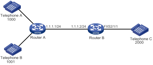
You can configure caller control either on the calling side or on the called side to meet the requirement.
· Method 1: Configure the calling side to permit only the calling number 1000 to call the number 2000.
[RouterA] voice-setup
[RouterA-voice] dial-program
[RouterA-voice-dial] entity 2000 voip
[RouterA-voice-dial-entity2000] match-template 2000
[RouterA-voice-dial-entity2000] address sip ip 1.1.1.2
[RouterA-voice-dial-entity2000] caller-permit 1000$
· Method 2: Configure the called side to permit only the calling number 1000 to call the number 2000.
[RouterB] voice-setup
[RouterB-voice] dial-program
[RouterB-voice-dial] entity 2000 pots
[RouterB-voice-dial-entity2000] match-template 2000
[RouterB-voice-dial-entity2000] caller-permit 1000$
[RouterB-voice-dial-entity2000] line 2/1/1
Configuring caller group control
Caller group control allows you to filter outgoing calls on the calling side or filter incoming calls on the called side based on caller groups. Caller group control is often used on the calling side.
A caller group references a subscriber group that defines the matching calling numbers. After you bind a caller group to a voice entity on the calling side, only the permitted calling numbers can call the called numbers on the voice entity.
Configuring a subscriber group
|
Step |
Command |
Remarks |
|
1. Enter system view. |
system-view |
N/A |
|
2. Enter voice view. |
voice-setup |
N/A |
|
3. Enter dial program view. |
dial-program |
N/A |
|
4. Create a subscriber group and enter its view. |
subscriber-group group-id |
By default, no subscriber groups exist. You can configure a maximum of 10 subscriber groups. |
|
5. (Optional.) Configure a description for the subscriber group. |
description text |
By default, no description is configured for a subscriber group. |
|
6. Configure a match template for the subscriber group. |
match-template match-string |
By default, no match templates are configured for a subscriber group. You can configure multiple match templates for a subscriber group. |
Configuring a caller group on a voice entity
|
Step |
Command |
Remarks |
|
1. Enter system view. |
system-view |
N/A |
|
2. Enter voice view. |
voice-setup |
N/A |
|
3. Enter dial program view. |
dial-program |
N/A |
|
4. Create a voice entity and enter its view. |
entity entity-number { ivr | pots | voip } |
By default, no voice entities exist. |
|
5. Configure the voice entity to permit or deny the calling numbers in the specified subscriber group. |
caller-group { deny | permit } group-id |
By default, all calling numbers are permitted. |
Enabling private line auto ring-down
The private line auto ring-down (PLAR) feature enables a subscriber line to automatically call the specified called number when the phone goes off-hook.
To configure the PLAR feature:
|
Step |
Command |
Remarks |
|
1. Enter system view. |
system-view |
N/A |
|
2. Enter subscriber line view. |
subscriber-line line-number |
N/A |
|
3. Configure PLAR. |
private-line string |
By default, PLAR is disabled. |
Configuring a number match mode
Two number match modes are available: longest match and shortest match.
Suppose you have configured match-template 0106688 on a voice entity and match-template 01066880011 on another voice entity.
When a subscriber dials 01066880011, the following rules apply:
· If shortest match is used, the router matches and calls the number 0106688.
· If longest match is used, the router matches and calls the number 01066880011.
When a subscriber dials 0106688, the following rules apply:
· If shortest match is used, the router matches and calls the number 0106688.
· If longest match is used, the router waits until the dial timer expires. Then the router matches the received number against match templates. If a match is found, the router calls the matching number. If no match is found, the router releases the call.
You can configure a terminator that identifies the end of a number. For example, suppose the terminator is the pound sign #. When a subscriber dials 0106688#, the router immediately matches the number 0106688 with match templates regardless of whether or not longest match is used. If a match is found, the router calls the matching number.
Procedure
To configure a number match mode:
|
Step |
Command |
Remarks |
|
1. Enter system view. |
system-view |
N/A |
|
2. Enter voice view. |
voice-setup |
N/A |
|
3. Enter dial program view. |
dial-program |
N/A |
|
4. Configure a number match mode. |
number-match { longest | shortest } |
By default, shortest match is used. |
|
5. Configure a terminator. |
terminator character |
By default, no terminator is configured. |
Examples
As shown in Figure 25, configure number match modes for calls from Telephone A to Telephones B and C.
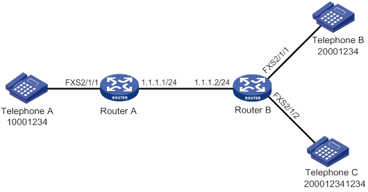
Using shortest match
1. Configure Router A:
# Configure POTS entity 1000.
<RouterA> system-view
[RouterA] voice-setup
[RouterA-voice] dial-program
[RouterA-voice-dial] entity 1000 pots
[RouterA-voice-dial-entity1000] match-template 10001234$
[RouterA-voice-dial-entity1000] line 2/1/1
[RouterA-voice-dial-entity1000] quit
# Configure VoIP entity 2000 and VoIP entity 2001.
[RouterA-voice-dial] entity2000 voip
[RouterA-voice-dial-entity2000] match-template 20001234$
[RouterA-voice-dial-entity2000] address ip 1.1.1.2
[RouterA-voice-dial-entity2000] quit
[RouterA-voice-dial] entity2001 voip
[RouterA-voice-dial-entity2001] match-template 200012341234$
[RouterA-voice-dial-entity2001] address ip 1.1.1.2
[RouterA-voice-dial-entity2001] quit
2. Configure Router B:
# Configure POTS entity 2000 and POTS entity 2001.
<RouterB> system-view
[RouterB] voice-setup
[RouterB-voice] dial-program
[RouterB-voice-dial] entity 2000 pots
[RouterB-voice-dial-entity2000] match-template 20001234$
[RouterB-voice-dial-entity2000] line 2/1/1
[RouterB-voice-dial-entity2000] quit
[RouterB-voice-dial] entity2001 pots
[RouterB-voice-dial-entity2001] match-template 200012341234$
[RouterB-voice-dial-entity2001] line 2/1/2
After you dial number 20001234 at Telephone A, the number matches VoIP entity 2000 and Telephone B rings because the device uses shortest match mode by default.
Configuring longest match
# Configure the longest match mode on Router A.
[RouterA-voice-dial] number-match longest
After you dial number 20001234 at Telephone A and waits for a period of time, the number matches VoIP entity 2000 and Telephone B rings. If you dial 1234 during the waiting period (the dialed number is 200012341234), the number matches VoIP entity 2001 and Telephone C rings.
Configuring a terminator
# Configure the terminator # on Router A.
[RouterA-voice-dial] terminator #
After you dial 20001234# at Telephone A, the number immediately matches VoIP entity 2000 and Telephone B rings.
Configuring the maximum number of calls allowed by a voice entity
You can limit the maximum number of calls allowed by a voice entity. The device stops establishing new calls when the limit is reached.
To configure the maximum number of calls allowed:
|
Step |
Command |
Remarks |
|
1. Enter system view. |
system-view |
N/A |
|
2. Enter voice view. |
voice-setup |
N/A |
|
3. Enter dial program view. |
dial-program |
N/A |
|
4. Enter voice entity view. |
entity entity-number { ivr | pots | voip } |
N/A |
|
5. Set the maximum number of calls allowed by the voice entity. |
max-conn max-number |
By default, the number of calls allowed by a voice entity is not limited. |
Configuring number substitution
A number substitution rule replaces a matching number with another number. You can configure number substation rules and then apply these rules globally or to voice entities and voice interfaces.
A number substitution process is as follows:
1. The router first matches a number against the preferred number substitution rule. If they match, the router replaces the number based on the preferred rule.
2. If the match fails, the router matches the number against other number substitution rules in sequence. Once a rule is matched, the router replaces the number based on the matching rule and stops matching other number substitution rules.
Number substitution on the calling router
As shown Figure 26, the calling router performs number substitution for a number as follows:
1. The router receives a call on a voice interface.
2. The router matches the calling or called number of the call against different types of number substitution rules in the following order:
a. Rules on the voice entity.
b. Global rules.
c. Rules on the incoming voice entity (if the number matches one).
d. Rules on the outgoing voice entity (if the number matches one).
If a match is found for a rule type, the router replaces the number, and matches the new number against the next rule type. If no match is found for a rule type, the router keeps matching the number against the next rule type. This matching process continues until all rule types are matched. For each rule type, the router performs only one number substitution.
3. The router places the call to the called party.
Figure 26 Flow chart for number substitution on the calling router
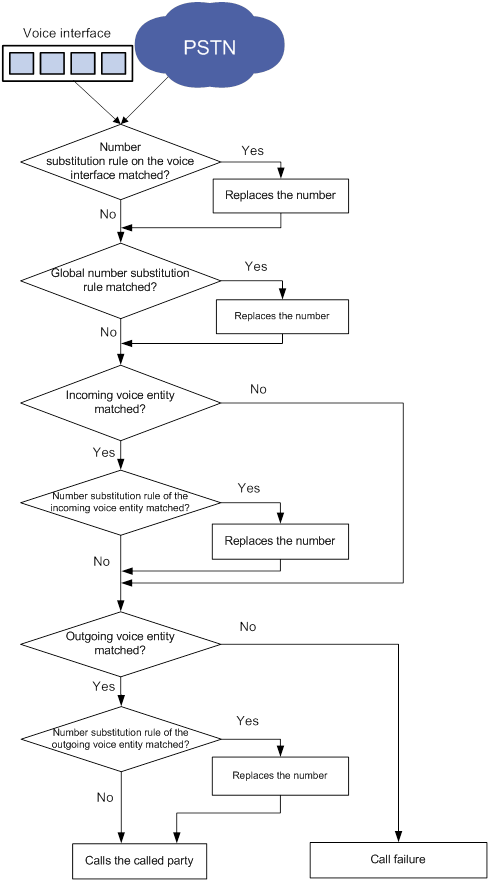
Number substitution on the called router
As shown Figure 27, the called router performs number substitution for a number as follows:
1. The router receives a call.
2. The router matches the called number against different types of number substitution rules in the following order:
a. Global rules.
b. Rules on the incoming voice entity (if the number matches one).
c. Rules on the outgoing voice entity (if the number matches one).
If a match is found for a rule type, the router replaces the number, and matches the new number against the next rule type. If no match is found for a rule type, the router keeps matching the number against the next rule type. The matching process continues until all rule types are matched. For each type, the router performs only one number substitution.
3. The router calls the called number if the called party is on a local voice interface, or initiates a call to the PSTN if the called party is in the PSTN.
Figure 27 Flow chart for number substitution on the called router
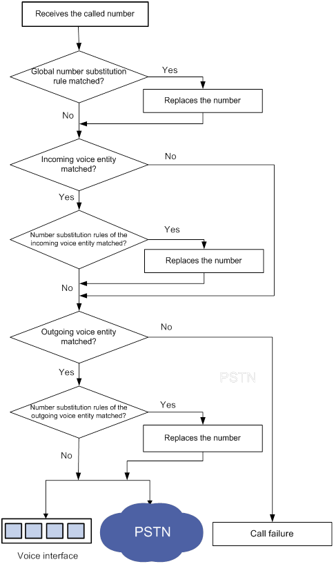
Configuring global number substitution
|
Step |
Command |
Remarks |
|
1. Enter system view. |
system-view |
N/A |
|
2. Enter voice view. |
voice-setup |
N/A |
|
3. Enter dial program view. |
dial-program |
N/A |
|
4. Create a number substitution rule list and enter its view. |
number-substitute list-number |
By default, no number substitution rule list exists. |
|
5. Configure a dot-match rule. |
dot-match { end-only | left-right | right-left } |
By default, the dot match rule is end-only. |
|
6. Configure a number substitution rule. |
By default, no number substitution rules exist. |
|
|
7. (Optional.) Configure the preferred number substitution rule. |
first-rule id |
By default, no preferred number substitution rule exists. |
|
8. Return to dial program view. |
quit |
N/A |
|
9. Apply the number substitution rule list to the calling/called number of incoming/outgoing calls. |
substitute { incoming-call | outgoing-call } { called | calling } list-number |
By default, no number substitution rule list is applied (no number substitution is performed). |
Configuring number substitution for a voice entity
|
Step |
Command |
Remarks |
|
1. Enter system view. |
system-view |
N/A |
|
2. Enter voice view. |
voice-setup |
N/A |
|
3. Enter dial program view. |
dial-program |
N/A |
|
4. Create a number substitution rule list and enter its view. |
number-substitute list-number |
By default, no number substitution rule list exists. |
|
5. Configure a dot match rule. |
dot-match { end-only | left-right | right-left } |
By default, the dot match rule is end-only. |
|
6. Configure a number substitution rule. |
rule id input-template output-template [ number-type input-number-type output-number-type | numbering-plan input-numbering-plan output-numbering-plan ] * |
By default, no number substitution rules exist. |
|
7. (Optional.) Configure the preferred number substitution rule. |
first-rule id |
By default, no preferred number substitution rule exists. |
|
8. Return to dial program view. |
quit |
N/A |
|
9. Enter voice entity view. |
entity entity-number { ivr | pots |voip } |
N/A |
|
10. Apply the number substitution rule list to the voice entity. |
substitute { called | calling } list-number |
By default, no number substitution rule list is applied to a voice entity. (The voice entity does not perform number substitution.) |
Configuring number substitution for a voice interface
|
Step |
Command |
Remarks |
|
1. Enter system view. |
system-view |
N/A |
|
2. Enter voice view. |
voice-setup |
N/A |
|
3. Enter dial program view. |
dial-program |
N/A |
|
4. Create a number substitution rule list and enter its view. |
number-substitute list-number |
By default, no number substitution rule lists exist. |
|
5. Configure a dot match rule. |
dot-match { end-only | left-right | right-left } |
By default, the dot match rule is end-only. |
|
6. Configure a number substitution rule. |
rule rule-tag input-template output-template [ number-type input-number-type output-number-type | numbering-plan input-numbering-plan output-numbering-plan ] * |
By default, no number substitution rules exist. |
|
7. (Optional.) Configure the preferred number substitution rule. |
first-rule rule-number |
By default, no preferred number substitution rule exists. |
|
8. Return to dial program view. |
quit |
N/A |
|
9. Return to voice view. |
voice-setup |
N/A |
|
10. Return to system view. |
system-view |
N/A |
|
11. Enter voice interface view. |
subscriber-line line-number |
N/A |
|
12. Apply the number substitution rule list to the voice interface. |
substitute { called | calling } list-number |
By default, no number substitution rule list is applied to a voice interface. (The voice entity does not perform number substitution.) |
Examples
Figure 28 Network diagram
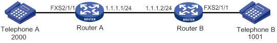
Configuring global number substitution
# Create number substitution rule list 1 and add a rule to the list.
[RouterA] voice-setup
[RouterA-voice] dial-program
[RouterA-voice-dial] number-substitute 1
[RouterA-voice-dial-substitute1] rule 0 ^010....$ ....
[RouterA-voice-dial-substitute1] quit
# Configure the destination address as 1.1.1.2 and the called number as 1001 for VoIP entity 1001.
[RouterA-voice-dial] entity 1001 voip
[RouterA-voice-dial-entity1001] address sip ip 1.1.1.2
[RouterA-voice-dial-entity1001] match-template 1001
[RouterA-voice-dial-entity1001] quit
# Apply number substitution rule list 1 to the called number of outgoing calls.
[RouterA-voice-dial] substitute outgoing-call called 1
When you use Telephone A to call number 0101001, Router A replaces 0101001 with 1001 and sends the call to the destination address 1.1.1.2. Then Telephone B rings.
Configuring voice entity number substitution
# Create number substitution rule list 1 and add a rule to the list.
[RouterA] voice-setup
[RouterA-voice] dial-program
[RouterA-voice-dial] number-substitute 1
[RouterA-voice-dial-substitute1] rule 0 ^010....$ ....
[RouterA-voice-dial-substitute1] quit
[RouterA-voice-dial] entity 1001 voip
[RouterA-voice-dial-entity1001] address sip ip 1.1.1.2
[RouterA-voice-dial-entity1001] match-template 0101001
# Apply number substitution rule list 1 to the called number on VoIP entity 1001.
[RouterA-voice-dial-entity1001] substitute called 1
When you use Telephone A to call number 0101001, VoIP entity 1001 replaces 0101001 with 1001 and sends the call to the destination address 1.1.1.2. Then Telephone B rings.
Configuring voice interface number substitution
# Create number substitution rule list 1 and add a rule to the list.
<RouterA> system-view
[RouterA] voice-setup
[RouterA-voice] dial-program
[RouterA-voice-dial] number-substitute 1
[RouterA-voice-dial-substitute1] rule 0 ^010....$ ....
[RouterA-voice-dial-substitute1] quit
# Configure the destination address as 1.1.1.2 and the called number as 1001 for VoIP entity 1001.
[RouterA-voice-dial] entity 1001 voip
[RouterA-voice-dial-entity1001] address sip ip 1.1.1.2
[RouterA-voice-dial-entity1001] match-template 1001
[RouterA-voice-dial-entity1001] quit
[RouterA-voice-dial] quit
[RouterA-voice] quit
# Apply number substitution rule list 1 to the called number on FXS interface 2/1/1.
[RouterA] subscriber-line 2/1/1
[RouterA-voice-line2/1/1] substitute called 1
When you use Telephone A to call number 0101001, FXS interface 2/1/1 replaces 0101001 with 1001 and sends the call to the destination address 1.1.1.2. Then Telephone B rings.
Configuring a priority for a voice entity
If a number matches multiple voice entities, the router selects the voice entity with the highest priority.
To configure a priority for a voice entity:
|
Step |
Command |
Remarks |
|
1. Enter system view. |
system-view |
N/A |
|
2. Enter voice view. |
voice-setup |
N/A |
|
3. Enter dial program view. |
dial-program |
N/A |
|
4. Enter voice entity view. |
entity entity-number { ivr | pots | voip } |
N/A |
|
5. Configure a priority for the voice entity. |
priority priority |
By default, the priority for a voice entity is 0. |
Configuring the voice entity selection order
If a number matches multiple voice entities, the router selects a voice entity based on the configured selection order.
To configure a voice entity selection order:
|
Step |
Command |
Remarks |
|
1. Enter system view. |
system-view |
N/A |
|
2. Enter voice view. |
voice-setup |
N/A |
|
3. Enter dial program view. |
dial-program |
N/A |
|
4. Configure a voice entity selection order. |
entity hunt hunt-number |
The default hunt-number is 0, which specifies longest match, voice entity priority, and random selection. For information about these selection rules, see this command in Voice Command Reference. |
Configuring a number sending mode
The number sending mode controls how the originating router sends a called number. The router supports the following number sending modes:
· Sends the least significant digits of a called number. The number of the least significant digits is specified by using the send-number digit-number command.
· Sends all the digits of a called number.
· Sends a truncated called number. When the match-template command configured for a voice entity contains dots (.), only the digits that match the dots are sent.
Procedure
To configure a number sending mode:
|
Step |
Command |
Remarks |
|
1. Enter system view. |
system-view |
N/A |
|
2. Enter voice view. |
voice-setup |
N/A |
|
3. Enter dial program view. |
dial-program |
N/A |
|
4. Enter POTS voice entity view. |
entity entity-number pots |
N/A |
|
5. Configure a number sending mode. |
send-number { digit-number | all | truncate } |
By default, the truncate mode is used. |
Examples
As shown in Figure 29, Router A and Router B connect to each other through an IP link and an E1 link. The telephones at two sides call each other through the E1 link. This section provides examples for configuring number sending modes to achieve different call policies.
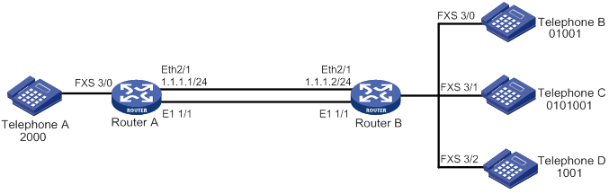
Configuring basic settings
# Configure a timeslot set using R2 signaling for controller E1 2/4/1.
<RouterA> system-view
[RouterA-E1 2/4/1] timeslot-set 0 timeslot-list 1-31 signal r2
[RouterA-E1 2/4/1] quit
[RouterA] voice-setup
[RouterA-voice] dial-program
# Configure a match template to match 010….$ for POTS entity 1001 and bind line 2/4/1:0 to the entity.
[RouterA-voice-dial] entity 1001 pots
[RouterA-voice-dial-entity1001] match-template 010....$
[RouterA-voice-dial-entity1001] line 2/4/1:0
# Configure a local number 2000 for POTS entity 2000, and bind line 2/1/1 to the entity.
[RouterA-voice-dial] entity 2000 pots
[RouterA-voice-dial-entity2000] match-template 2000
[RouterA-voice-dial-entity2000] line 2/1/1
# Configure a timeslot set using R2 signaling for controller E1 2/4/1.
<RouterB> system-view
[RouterB-E1 2/4/1] timeslot-set 0 timeslot-list 1-31 signal r2
[RouterB-E1 2/4/1] quit
# Configure a local number 01001 for POTS entity 1002, and bind line 2/1/1 to the entity.
[RouterB-voice] dial-program
[RouterB] voice-setup
[RouterB-voice] dial-program
[RouterB-voice-dial] entity 1002 pots
[RouterB-voice-dial-entity1002] match-template 01001
[RouterB-voice-dial-entity1002] line 2/1/1
[RouterB-voice-dial-entity1002] quit
# Configure a local number 0101001 for POTS entity 0101001, and bind line 2/1/2 to the entity.
[RouterB-voice-dial] entity 0101001 pots
[RouterB-voice-dial-entity101001] match-template 0101001
[RouterB-voice-dial-entity101001] line 2/1/2
[RouterB-voice-dial-entity101001] quit
# Configure a local number 1001 for POTS entity 1001, and bind line 2/1/3 to the entity.
[RouterB-voice-dial] entity 1001 pots
[RouterB-voice-dial-entity1001] match-template 1001
[RouterB-voice-dial-entity1001] line 2/1/3
[RouterB-voice-dial-entity1001] quit
Configuring number sending modes on Router A
# Configure Router A to send the five least significant digits of a called number.
[RouterA-voice-dial-entity1001] send-number 5
If you use Telephone A to call 0101001, Router A sends the called number 01001, which are the five least significant digits. Then Telephone B rings.
# Configure Router A to send all the digits of a called number.
[RouterA-voice-dial-entity1001] send-number all
# Configure Router A to send a truncated called number.
[RouterA-voice-dial-entity1001] send-number truncate
If you use Telephone A to call 0101001, Router A sends the called number 1001, which match the dots in "010….$". Then Telephone D rings.
Configuring a dial prefix
After you configure a dial prefix, the router adds the prefix before each called number. If the called number exceeds 31 digits, the router sends only the first 31 digits.
To configure a dial prefix:
|
Step |
Command |
Remarks |
|
1. Enter system view. |
system-view |
N/A |
|
2. Enter voice view. |
voice-setup |
N/A |
|
3. Enter dial program view. |
dial-program |
N/A |
|
4. Enter POTS entity view. |
entity entity-number pots |
N/A |
|
5. Configure a dial prefix. |
dial-prefix string |
By default, no dial prefix is configured. |
Dial program configuration examples
This section provides dial program configuration examples.
Configuring number substitution
Network requirements
As shown in Figure 30, configure number substitution on the routers so departments in different areas can call each other by using the area code of the destination area plus a four-digit local number.
For example, to use phone 1688 of the F department in area B to call phone 6788 of the M department in area A, dial the number 0103366. The sequence 3366 is the number of the M department in area B.
On phone 6788, the calling number 1688 is displayed as 0211234, which is the area code of area A plus the number of the F department in area A.
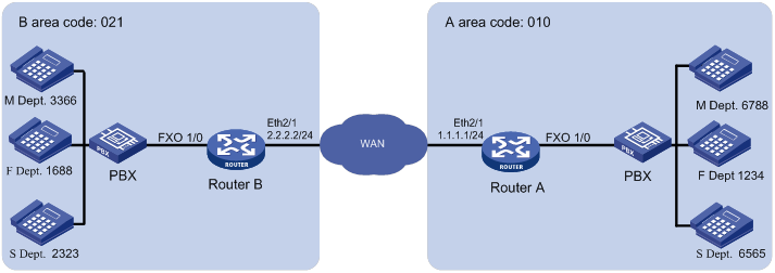
Configuration procedure
The following provides the number substitution configuration only for calls from area B to area A.
1. Configure Router B:
# Create number substitution rule list 21101 and add rules to the list.
[RouterB] voice-setup
[RouterB-voice] dial-program
[RouterB-voice-dial] number-substitute 21101
[RouterB-voice-dial-substitute21101] rule 1 ^0101688$ 0001
[RouterB-voice-dial-substitute21101] rule 2 ^0103366$ 0002
[RouterB-voice-dial-substitute21101] rule 3 ^0102323$ 0003
[RouterB-voice-dial-substitute21101] quit
# Create number substitution rule list 21102 and add rules to the list.
[RouterB-voice-dial] number-substitute 21102
[RouterB-voice-dial-substitute21102] rule 1 ^1688$ 0210001
[RouterB-voice-dial-substitute21102] rule 2 ^3366$ 0210002
[RouterB-voice-dial-substitute21102] rule 3 ^2323$ 0210003
[RouterB-voice-dial-substitute21102] quit
# Configure the match template 010.... to match called numbers, and set the destination IP address as 1.1.1.1 for VoIP entity 10.
[RouterB-voice-dial] entity 10 voip
[RouterB-voice-dial-entity10] match-template 010....
[RouterB-voice-dial-entity10] address sip ip 1.1.1.1
# Apply the number substitution rule list 21101 to called numbers on VoIP entity 10. This will change the called numbers 0101688, 0103366, and 0102323 into 0001, 0002, and 0003 respectively.
[RouterB-voice-dial-entity10] substitute called 21101
# Apply the number substitution rule list 21102 to calling numbers on VoIP entity 10. This will change the calling numbers 1688, 3366, and 2323 into 0210001, 0210002, and 0210003 respectively.
[RouterB-voice-dial-entity10] substitute calling 21102
2. Configure Router A:
# Create number substitution rule list 101 and add rules to the list.
[RouterA] voice-setup
[RouterA-voice] dial-program
[RouterA-voice-dial] number-substitute 101
[RouterA-voice-dial-substitute101] rule 1 ^0001$ 1234
[RouterA-voice-dial-substitute101] rule 2 ^0002$ 6788
[RouterA-voice-dial-substitute101] rule 3 ^0003$ 6565
[RouterA-voice-dial-substitute101] quit
# Create number substitution rule list 102 and add rules to the list.
[RouterA-voice-dial] number-substitute 102
[RouterA-voice-dial-substitute102] dot-match left-right
[RouterA-voice-dial-substitute102] rule 1 ^...0001$ ...1234
[RouterA-voice-dial-substitute102] rule 2 ^...0002$ ...6788
[RouterA-voice-dial-substitute102] rule 3 ^...0003$ ...6565
[RouterA-voice-dial-substitute102] quit
# Apply the number substitution rule list 101 to the called numbers of incoming calls. This will change the called numbers 0001, 0002, and 0003 into 1234, 6788, and 6565 respectively.
[RouterA-voice-dial] substitute incoming-call called 101
# Apply the number substitution rule list 102 to the calling numbers of incoming calls. This will change the called numbers 0210001, 0210002, and 0210003 into 0211234, 0216788, and 0216565 respectively.
[RouterA-voice-dial] substitute incoming-call calling 102
# Configure the match template …. for POTS entity 1010, bind line 2/1/1 to the entity, and configure the entity to send all the digits of a called number.
[RouterA-voice-dial] entity 1010 pots
[RouterA-voice-dial-entity1010] match-template ....
[RouterA-voice-dial-entity1010] line 2/1/1
[RouterA-voice-dial-entity1010] send-number all
Verifying the configuration
# Use phone 1688 to dial the number 0103366 to verify that phone 6788 rings and the displayed calling number is 0211234.
During the calling process, Router B changes the calling number 1688 into 0210001 and changes the called number 0103366 into 0002. Then Router A changes 0210001 into 0211234 and changes 0002 into 6788.
Configuring caller group control
Network requirements
As shown in Figure 31, areas A, B, and C call each other through the SIP server. Configure caller group control on Router A so when the SIP server fails, the areas call each other though the public PBXs in PSTN as follows:
· The phone numbers starting with 1100 in area A can only call the phone numbers in area B.
· The phone numbers starting with 1200 in area A can call the phone numbers both in area B and area C.
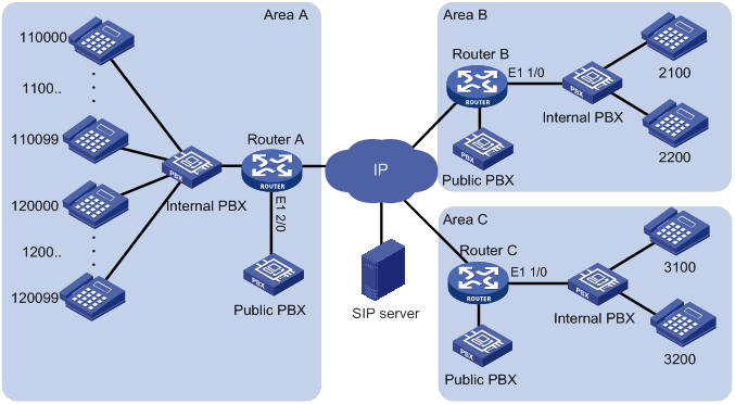
Configuration procedure
This example does not provide SIP server and digital voice interface configurations. For information about configuring SIP servers and digital voice interfaces, see "Configuring SIP" and "Configuring voice interfaces."
1. Configure Router A:
# Configure subscriber group 1 that matches calling numbers starting with 1100 and configure subscriber group 2 that matches calling numbers starting with 1200.
<RouterA> system-view
[RouterA] voice-setup
[RouterA-voice] dial-program
[RouterA-voice-dial] subscriber-group 1
[RouterA-voice-dial-group1] match-template 1100..
[RouterA-voice-dial-group1] quit
[RouterA-voice-dial] subscriber-group 2
[RouterA-voice-dial-group2] match-template 1200..
[RouterA-voice-dial-group2] quit
# Configure VoIP entity 2000 to use the SIP proxy server to find call destination addresses and to match called numbers in area B.
[RouterA-voice-dial] entity 2000 voip
[RouterA-voice-dial-entity2000] address sip proxy
[RouterA-voice-dial-entity2000] match-template 2...
[RouterA-voice-dial-entity2000] quit
# Configure VoIP entity 3000 to use the SIP proxy server to find call destination addresses and to match called numbers in area C.
[RouterA-voice-dial] entity 3000 voip
[RouterA-voice-dial-entity3000] address sip proxy
[RouterA-voice-dial-entity3000] match-template 3...
[RouterA-voice-dial-entity3000] quit
# Configure a caller group to permit subscriber groups 1 and 2 on POTS entity 2100 so the phone numbers starting with 1100 or 1200 in area A can call the phone numbers in area B.
[RouterA-voice-dial] entity 2100 pots
[RouterA-voice-dial-entity2100] line 2/0:15
[RouterA-voice-dial-entity2100] send-number all
[RouterA-voice-dial-entity2100] match-template 2...
[RouterA-voice-dial-entity2100] caller-group permit 1
[RouterA-voice-dial-entity2100] caller-group permit 2
[RouterA-voice-dial-entity2100] quit
# Configure a caller group to permit subscriber group 2 on POTS entity 3100 so the phone numbers starting with 1200 in area A can call the phone numbers in area C.
[RouterA-voice-dial] entity 3100 pots
[RouterA-voice-dial-entity3100] line 2/0:15
[RouterA-voice-dial-entity3100] send-number all
[RouterA-voice-dial-entity3100] match-template 3...
[RouterA-voice-dial-entity3100] caller-group permit 2
[RouterA-voice-dial] quit
# Configure POTS entity 2100 to match local numbers and bind line 2/1/1:15 to the entity.
[RouterA-voice-dial] entity 2100 pots
[RouterA-voice-dial-entity2100] line 2/1/1:15
[RouterA-voice-dial-entity2100] send-number all
[RouterA-voice-dial-entity2100] match-template 1.....
2. Configure Router B:
# Configure POTS entity 2100 to match local numbers and bind line 2/1/1:15 to the entity.
[RouterB] voice-setup
[RouterB-voice] dial-program
[RouterB-voice-dial] entity 2100 pots
[RouterB-voice-dial-entity2100] line 2/1/1:15
[RouterB-voice-dial-entity2100] send-number all
[RouterB-voice-dial-entity2100] match-template 2...
3. Configure Router C:
# Configure POTS entity 3100 to match local numbers and bind line 2/1/1:15 to the entity.
[RouterC] voice-setup
[RouterC-voice] dial-program
[RouterC-voice-dial] entity 3100 pots
[RouterC-voice-dial-entity3100] line 2/1/1:15
[RouterC-voice-dial-entity3100] send-number all
[RouterC-voice-dial-entity3100] match-template 3...
Verifying the configuration
# Place calls to verify that the phone numbers starting with 1100 in area A can only call the phone numbers in area B.
# Place calls to verify that the phone numbers starting with 1200 in area A can call the phone numbers both in area B and area C.
Configuring the maximum number of calls
Network requirements
As shown in Figure 32, configure the maximum number of calls placed from Router A and Router B to Router C.
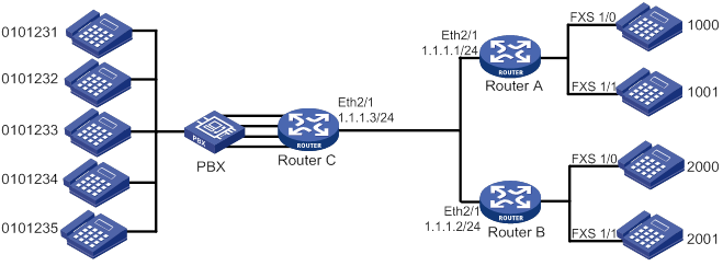
Configuration procedure
1. Configure Router A:
# Configure the called number template as 010…. for VoIP entity 2000, and configure the destination IP address as 1.1.1.3.
[RouterA] voice-setup
[RouterA-voice] dial-program
[RouterA-voice-dial] entity 2000 voip
[RouterA-voice-dial-entity2000] match-template 010....
[RouterA-voice-dial-entity2000] address sip ip 1.1.1.3
[RouterA-voice-dial-entity2000] quit
# Configure the local number as 1000 for POTS entity 1000, and bind FXS interface line 2/1/1 to the POTS entity.
[RouterA-voice-dial] entity 1000 pots
[RouterA-voice-dial-entity1000] match-template 1000
[RouterA-voice-dial-entity1000] line 2/1/1
[RouterA-voice-dial-entity1000] quit
# Configure the local number as 1001 for POTS entity 1001, and bind FXS interface line 1/1 to the POTS entity.
[RouterA-voice-dial] entity 1001 pots
[RouterA-voice-dial-entity1001] match-template 1001
[RouterA-voice-dial-entity1001] line 1/1
[RouterA-voice-dial-entity1001] quit
# Configure the maximum number of calls allowed by VoIP entity 2000 as 2.
[RouterA-voice-dial] entity 2000 voip
[RouterA-voice-dial-entity2000] max-conn 2
2. Configure Router B:
# Configure the called number template as 010…. for VoIP entity 1000, and configure the destination IP address as 1.1.1.3.
[RouterB] voice-setup
[RouterB-voice] dial-program
[RouterB-voice-dial] entity 1000 voip
[RouterB-voice-dial-entity1000] match-template 010....
[RouterB-voice-dial-entity1000] address sip ip 1.1.1.3
[RouterB-voice-dial-entity1000] quit
# Configure the local number as 2000 for POTS entity 2000, and bind FXS interface line 2/1/1 to the POTS entity.
[RouterB-voice-dial] entity 2000 pots
[RouterB-voice-dial-entity2000] match-template 2000
[RouterB-voice-dial-entity2000] line 2/1/1
[RouterB-voice-dial-entity2000] quit
# Configure the local number as 2001 for POTS entity 2001, and bind FXS interface line 1/1 to the POTS entity.
[RouterB-voice-dial] entity 2001 pots
[RouterB-voice-dial-entity2001] match-template 2001
[RouterB-voice-dial-entity2001] line 1/1
[RouterB-voice-dial-entity2001] quit
# Configure the maximum number of calls allowed by VoIP entity 1000 as 2.
[RouterB-voice-dial] entity 1000 voip
[RouterB-voice-dial-entity1000] max-conn 2
3. Configure Router C:
# Configure the local number template as 010…. for POTS entity 1000, bind FXO interface line 5/0 to the POTS entity, and configure the number sending mode as all.
<RouterC> system-view
[RouterC-voice-dial] entity 1000 pots
[RouterC-voice-dial-entity1000] match-template 010....
[RouterC-voice-dial-entity1000] line 5/0
[RouterC-voice-dial-entity1000] send-number all
[RouterC-voice-dial-entity1000] quit
# Configure the local number template as 010…. for POTS entity 1001, bind FXO interface line 5/1 to the POTS entity, and configure the number sending mode as all.
[RouterC-voice-dial] entity 1001 pots
[RouterC-voice-dial-entity1001] match-template 010....
[RouterC-voice-dial-entity1001] line 5/1
[RouterC-voice-dial-entity1001] send-number all
[RouterC-voice-dial-entity1001] quit
# Configure the local number template as 010…. for POTS entity 1002, bind FXO interface line 5/2 to the POTS entity, and configure the number sending mode as all.
[RouterC-voice-dial] entity 1002 pots
[RouterC-voice-dial-entity1002] match-template 010....
[RouterC-voice-dial-entity1002] line 5/2
[RouterC-voice-dial-entity1002] send-number all
[RouterC-voice-dial-entity1002] quit
# Configure the local number template as 010…. for POTS entity 1003, bind FXO interface line 5/3 to the POTS entity, and configure the number sending mode as all.
[RouterC-voice-dial] entity 1003 pots
[RouterC-voice-dial-entity1003] match-template 010....
[RouterC-voice-dial-entity1003] line 5/3
[RouterC-voice-dial-entity1003] send-number all
Verifying the configuration
# Initiate the maximum number of concurrent calls, for example, from 1000 and 1001. (Details not shown.)
# Initiate a call while the above calls are present to verify that the call is rejected. (Details not shown.)
Configuring SIP
Overview
The Session Initiation Protocol (SIP) is an application layer control protocol that can create, modify, and terminate multimedia sessions such as voice and video calls over IP networks.
Terminology
User agent
A user agent (UA) is a SIP endpoint such as a phone, a gateway, or a router.
There are two types of UAs: user agent client (UAC) and user agent server (UAS). A UAC sends SIP requests, and a UAS receives SIP requests and returns SIP responses. These roles of UAC and UAS only last for the duration of a SIP transaction.
Proxy server
A proxy server primarily forwards session requests and responses. It can also provide call control, accounting, and authorization functions.
Redirect server
A redirect server sends new addresses to UACs so the UAC sends session requests to the new addresses.
Location server
A location server provides UA information to proxy and redirect servers.
Registrar
A registrar receives registrations from UAs and generates UA information. The UA information is stored on the location server.
SIP functions
SIP supports the following facets of establishing and terminating multimedia communications:
· User location—Determines the end system to be used for communication. SIP can use UA information on the registrar or use information provided by DNS or LDAP to locate end systems.
· User availability—Determines the willingness of the called party to engage in communications.
· User capabilities—Determines the media type and media parameters to be used. In a message exchange process, each SIP endpoint advertises media information so that all other participants can learn about its capabilities.
· Session establishment—Establishes session parameters at both called and calling parties.
· Session management—Transfers and terminates sessions, modifies session parameters, and invokes services.
SIP messages
SIP is a text-based protocol. A SIP message is either a request from a client to a server, or a response from a server to a client.
SIP requests include INVITE, ACK, OPTIONS, BYE, CANCEL, and REGISTER.
· INVITE—Invites a user to join a call.
· ACK—Acknowledges the response to a request.
· OPTIONS—Queries for the capabilities.
· BYE—Releases an established call.
· CANCEL—Gives up a call attempt.
· REGISTER—Registers with the SIP registrar.
SIP responses indicate the status of a call or registration. Responses are distinguished by status codes. As shown in Table 9, each status code is a 3-digit integer, where the first digit defines the class of the response, and the last two digits describe the response message in more detail.
Table 9 Status codes of responses
|
Code |
Description |
Class |
|
100–199 |
The request was received and is being processed. |
Provisional |
|
200–299 |
The request was successfully received, understood, and accepted. |
Success |
|
300–399 |
A further action must be taken to complete the request. |
Redirection |
|
400–499 |
The request contains bad syntax or cannot be fulfilled at this server. |
Client failure |
|
500–599 |
The server failed to fulfill an apparently valid request. |
Server failure |
|
600–699 |
The request cannot be fulfilled at any server. |
Global failure |
Transport protocols supported by SIP
SIP supports the following transport protocols:
· UDP—Connectionless and unreliable. SIP connections over UDP are unreliable.
· TCP—Connection-oriented and reliable. TCP solves packet loss and retransmission issues for SIP messages and voice packets. SIP also supports Transport Layer Security (TLS) over TCP. TLS over TCP provides security for SIP messages. For more information, see "Signaling authentication and encryption."
When active calls are present, switching transport protocols is not supported.
SIP security
Signaling authentication and encryption
TLS over TCP provides a security solution for mutual authentication and encryption. The two communication parties authenticate each other by using digital certificates before establishing a TLS connection. SIP messages are encrypted over the TLS connection. For more information about TLS, see "Configuring TLS as the transport protocol." To use TLS for SIP, you must also configure TLS security policies (see Security Configuration Guide).
Media authentication and encryption
SIP supports two media stream protocols: Real-Time Transport Protocol (RTP) and Real-Time Transport Control Protocol (RTCP). RTP provides end-to-end transmission for real-time data, such as interactive voice and video. RTCP monitors transmission quality and provides congestion control and flow control. RTP and RTCP work together to achieve optimal transmission efficiency by providing efficient feedback and minimizing overheads.
Secure Real-Time Transport Protocol (SRTP) enhances RTP by encrypting RTP/RTCP packets and providing authentication and retransmission. For information about configuring media stream protocols for SIP, see "Configuring SRTP for SIP calls."
SRTP requires encryption negotiation. The device supports encryption negotiation only through the crypto headers in the Session Description Protocol (SDP). The initiator of negotiation sends its encryption attributes to the peer, and the peer returns the attributes if it accepts them. Each party encrypts and decrypts RTP/RTCP packets by using the negotiated key.
Table 10 Negotiation attributes
|
Attribute |
Description |
Remarks |
|
Identifies a particular cryptographic attribute to determine which of the offered cryptographic attributes was chosen by the receiver. |
Mandatory. |
|
|
Defines the encryption and authentication algorithms. The device only supports the AES_CM_128_HMAC_SHA1_80 and AES_CM_128_HMAC_SHA1_32 suites. |
Mandatory. |
|
|
Includes the key generation method and key value. |
Mandatory. |
|
|
Includes the key derivation rate, UNENCRYPTED_SRTP, UNENCRYPTED_SRTCP, UNAUTHENTICATED_SRTP, and FEC. |
Optional; not supported. |
TLS and SRTP can be used separately or together. TLS can secure SIP messages (user information), and SRTP can secure media packets (the contents of calls). As a best practice, enable both TLS and SRTP.
Crypto engine for SIP
Signaling/media authentication and encryption can be implemented by software or hardware.
· Software implementation—Complex authentication and encryption/decryption algorithms consume excessive CPU resources and affect overall device processing efficiency.
· Hardware implementation—Complex algorithms are processed by the hardware crypto engine and have no impact on device processing efficiency. The device sends the data to the hardware crypto engine. After the crypto engine completes data encryption/decryption, it sends the data back to the device.
For more information about crypto engines, see Security Configuration Guide.
Feature and hardware compatibility
|
Hardware |
SIP compatibility |
|
MSR810/810-W/810-W-DB/810-LM/810-W-LM/810-10-PoE/810-LM-HK/810-W-LM-HK/810-LMS/810-LUS |
No |
|
MSR2600-6-X1/2600-10-X1 |
Yes |
|
MSR 2630 |
Yes |
|
MSR3600-28/3600-51 |
Yes |
|
MSR3600-28-SI/3600-51-SI |
No |
|
MSR3610-X1/3610-X1-DP/3610-X1-DC/3610-X1-DP-DC |
Yes |
|
MSR 3610/3620/3620-DP/3640/3660 |
Yes |
|
MSR5620/5660/5680 |
Yes (not supported on the router installed with an SPU600-X1 card.) |
|
Hardware |
SIP compatibility |
|
MSR810-LM-GL |
No |
|
MSR810-W-LM-GL |
No |
|
MSR830-6EI-GL |
No |
|
MSR830-10EI-GL |
No |
|
MSR830-6HI-GL |
No |
|
MSR830-10HI-GL |
No |
|
MSR2600-6-X1-GL |
Yes |
|
MSR3600-28-SI-GL |
No |
SIP configuration task list
Configuring SIP UA registration
A SIP UA registers with a SIP registrar as shown in Figure 33.
1. The SIP UA sends a REGISTER request to the registrar.
2. The registrar returns a 200 OK response to the UA if the registration is accepted.
Figure 33 Registration process
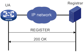
If the registrar needs to authenticate the UA, the UA registers with the registrar as shown in Figure 34.
3. The UA sends a REGISTER request to the registrar.
4. The registrar returns a 401/407 response, challenging the originator to provide credentials.
5. The UA sends a REGISTER request that includes credentials to the registrar.
6. The registrar returns a 200 OK response to the UA if the authentication succeeds.
Figure 34 Registration process with authentication
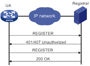
Configuration prerequisites
Complete the following tasks before you configure SIP credentials information:
· Configure a number template on each voice entity by using the match-template command. Bind each voice entity to a voice interface by using the line command.
· Enable the voice entities and voice interfaces (in undo shutdown state).
Configuring SIP credentials
If the registrar provides UA authentication, configure SIP credentials on the SIP UA in the following ways:
· Use the user command in SIP view to configure global SIP credentials.
· Use the credentials command to configure SIP credentials for a SIP trunk account. For more information about SIP trunk, see "Configuring SIP trunk."
· Use the user command in voice entity view to configure SIP credentials for a voice entity.
Registration with multiple registrars
A SIP UA can register with up to six registrars, and it uses the realm in the 401/407 response from a registrar to identify the credentials to be sent to the registrar.
You can configure only one username by using the user command in SIP view or voice entity view. The username can contain 12 credentials bindings. A binding that does not include a realm can be used to respond to a 401/407 response that does not match any realm-included binding. The following example configures four credentials bindings:
[Sysname-voice-dial-entity100] user 1000 password simple 1000 realm server1
[Sysname-voice-dial-entity100] user 1000 password simple 1000 realm server2
[Sysname-voice-dial-entity100] user 1000 password simple 2000 realm server3
[Sysname-voice-dial-entity100] user 1000 password simple 3000
The first three bindings each contain a realm, and the last binding contains no realm. If the SIP UA receives a 401/407 response that includes a realm server2, the SIP UA responds with the username 1000 and password 1000. If the SIP UA receives a 401/407 response that includes a realm server4, the SIP UA responds with the username 1000 and password 3000 because no credentials binding contains the realm server4.
Credentials selection for a phone number that exists on multiple voice entities
Upon receiving a 401/407 response for a phone number that exists on multiple voice entities, the SIP UA considers the phone number to belong to the voice entity with the smallest ID. The SIP UA selects the credentials for the phone number in the following order:
1. Credentials on the voice entity with the smallest ID.
2. Credentials configured by using the credentials command.
3. Credentials configured in SIP view.
The SIP UA always uses the matching credentials for the phone number even if a voice entity that has a higher match priority is added. If no matching credentials are found, the SIP UA fails to register the phone number.
For example, the registrar maintains the username abcd, password 1234, and domain name abc for the phone number 1000. The SIP UA has the following settings for the phone number 1000:
· POTS entity 1 maintains the username abcd, password 1234, and domain name aaa for the phone number 1000.
[Sysname] voice-setup
[Sysname-voice] dial-program
[Sysname-voice-dial] entity 1 pots
[Sysname-voice-dial-entity1] match-template 1000
[Sysname-voice-dial-entity1] user abcd password simple 1234 realm aaa
· POTS entity 2 maintains the username abcd, password 1234, and domain name abc for the phone number 1000.
[Sysname] voice-setup
[Sysname-voice] dial-program
[Sysname-voice-dial] entity 2 pots
[Sysname-voice-dial-entity2] match-template 1000
[Sysname-voice-dial-entity2] user abcd password simple 1234 realm abc
· The SIP trunk account maintains the username abcd, password 1234, and domain name abc for the phone number 1000.
[Sysname] voice-setup
[Sysname-voice] sip
[Sysname-voice-sip] credentials number 1000 username abcd password simple 1234 realm abc
· The global SIP credentials information includes the username abcd, password 1234, and domain name abc.
[Sysname] voice-setup
[Sysname-voice] sip
[Sysname-voice-sip] user abcd password simple 1234 realm abc
Upon receiving a 401/407 response for the phone number 1000, the SIP UA considers the phone number to belong to POTS entity 1. The SIP UA selects the credentials on POTS entity 1 because POTS entity 1 has a smaller ID, but the credentials fail the authentication. Then the SIP UA selects the credentials configured by using the credentials command, and the credentials pass the authentication. The output from the display voice sip register-status command shows that the phone number 1000 belongs to voice entity 1.
<Sysname> display voice sip register-status
Number Entity Registrar Server Expires Status
--------------------------------------------------------------------------------
1000 1 192.168.4.240:5060 2877 Online
Configuring global SIP credentials
|
Step |
Command |
Remarks |
|
1. Enter system view. |
system-view |
N/A |
|
2. Enter voice view. |
voice-setup |
N/A |
|
3. Enter SIP view. |
sip |
N/A |
|
4. Configure global SIP credentials. |
user username password { cipher | simple } string [ realm realm ] |
By default, no global SIP credentials exist. |
Configuring SIP credentials for a POTS entity
|
Step |
Command |
Remarks |
|
1. Enter system view. |
system-view |
N/A |
|
2. Enter voice view. |
voice-setup |
N/A |
|
3. Enter dial program view. |
dial-program |
N/A |
|
4. Enter POTS entity view. |
N/A |
|
|
5. Configure SIP credentials for the POTS entity. |
user username password { cipher | simple } string [ cnonce cnonce | realm realm ] * |
By default, no SIP credentials exist. |
Enabling a POTS entity to register with the registrar
Perform this task to enable a POTS entity to register with the registrar. You can also disable a POTS entity from registering with the registrar by using the undo register-number command if registration is not needed.
To enable a POTS entity to register with the registrar:
|
Step |
Command |
Remarks |
|
1. Enter system view. |
system-view |
N/A |
|
2. Enter voice view. |
voice-setup |
N/A |
|
3. Enter dial program view. |
dial-program |
N/A |
|
4. Enter POTS entity view. |
entity entity-number pots |
N/A |
|
5. Enable the POTS entity to register with the registrar. |
register-number |
By default, a POTS entity registers with the registrar after UA registration is configured. |
Specifying registrars
Perform this task to specify a registrar. The expires keyword sets the registration expiration time, and the refresh-ratio keyword sets the refresh percentage. When the registration time reaches the registration expiration time multiplied by the refresh percentage, a voice entity or SIP trunk re-registers the number with the registrar to avoid expiration.
To specify a registrar:
|
Step |
Command |
Remarks |
|
1. Enter system view. |
system-view |
N/A |
|
2. Enter voice view. |
voice-setup |
N/A |
|
3. Enter SIP view. |
sip |
N/A |
|
4. Specify a registrar. |
registrar registrar-index { ip ip-address | dns domain-name } [ port port-number ] [ expires seconds ] [ refresh-ratio ratio-percentage ] [ scheme { sip | sips } ] [ tcp [ tls ] ] |
By default, no registrars are specified. |
Configuring the call destination address for a VoIP entity
You can configure the call destination address for a VoIP entity in one of the following ways:
· Configure the call destination IP address.
· Configure the VoIP entity to obtain the call destination address from a proxy server.
· Configure the destination domain name and port number. Only DNS A records are supported. For more information about DNS, see Layer 3—IP Services Configuration Guide.
Configuring the call destination IP address for a VoIP entity
|
Step |
Command |
Remarks |
|
1. Enter system view. |
system-view |
N/A |
|
2. Enter voice view. |
voice-setup |
N/A |
|
3. Enter dial program view. |
dial-program |
N/A |
|
4. Enter VoIP entity view. |
entity entity-number voip |
N/A |
|
5. Configure the call destination IP address. |
address sip ip ip-address [ port port-number ] |
By default, no call destination IP address exists. |
Configuring a VoIP entity to obtain the call destination address from a proxy server
|
Step |
Command |
Remarks |
|
1. Enter system view. |
system-view |
N/A |
|
2. Enter voice view. |
voice-setup |
N/A |
|
3. Enter SIP view. |
N/A |
|
|
4. Specify the proxy server. |
proxy { dns domain-name port port-number | ip ip-address [ port port-number ] } |
By default, no proxy server is specified. |
|
5. Return to voice view. |
N/A |
|
|
6. Enter dial program view. |
dial-program |
N/A |
|
7. Enter VoIP entity view. |
entity entity-number voip |
N/A |
|
8. Enable the VoIP entity to obtain the call destination address from the proxy server. |
address sip proxy |
By default, a VoIP entity does not obtain the call destination address from the proxy server. |
Configuring the destination domain name and port number for a VoIP entity
|
Step |
Command |
Remarks |
|
1. Enter system view. |
system-view |
N/A |
|
2. Enter voice view. |
voice-setup |
N/A |
|
3. Enter dial program view. |
dial-program |
N/A |
|
4. Enter VoIP entity view. |
entity entity-number voip |
N/A |
|
5. Configure the destination domain name and port number. |
By default, no destination domain name or port number exists. |
Configuring out-of-dialog keepalive for a VoIP entity
After you enable out-of-dialog keepalive, the UA sends OPTIONS packets at the up-interval. If the UA receives a response within the up-interval, it considers the VoIP entity to be available. If the UA receives no response within the up-interval, or if it receives an error response, it sends OPTIONS packets at the timers options interval. (Error responses include 408, 499, and 5XX responses except for 500, 501, 502, 503, 504, and 513 responses.) If the UA still receives no responses after the maximum number of retries is reached, it considers the VoIP entity to be unavailable.
Then, the UA sends OPTIONS packets at the down-interval. If the UA receives a response within the down-interval, it sends OPTIONS packets at the timers options interval. If the UA still can receive responses after the number of retries is reached, it considers the VoIP entity to be available.
This feature does not take effect for a VoIP entity that has been shut down by using the shutdown command.
To enable out-of-dialog keepalive for a VoIP entity:
|
Step |
Command |
Remarks |
|
1. Enter system view. |
system-view |
N/A |
|
2. Enter voice view. |
voice-setup |
N/A |
|
3. Enter dial program view. |
dial-program |
N/A |
|
4. Enter VoIP entity view. |
entity entity-number voip |
N/A |
|
5. Enable out-of-dialog keepalive for the VoIP entity. |
By default, out-of-dialog keepalive is disabled for a VoIP entity. |
|
|
6. Return to voice view. |
N/A |
|
|
7. Enter SIP view. |
N/A |
|
|
8. Set the interval for sending OPTIONS messages. |
The default setting is 500 milliseconds. This interval takes effect only for VoIP entities that have been enabled with out-of-dialog keepalive. |
Configuring INVITE retransmission
The originating device starts an INVITE retry timer when sending an INVITE request. If no 100 response arrives when the timer expires, the originating device retransmits the INVITE request. If no 100 response arrives when the maximum number of INVITE retries is reached, the originating device clears the call.
To configure INVITE retransmission:
|
Step |
Command |
Remarks |
|
1. Enter system view. |
system-view |
N/A |
|
2. Enter voice view. |
voice-setup |
N/A |
|
3. Enter SIP view. |
sip |
N/A |
|
4. Set the maximum number of INVITE retries. |
retry invite times |
By default, the maximum number of INVITE retries is 6. |
|
5. Set the INVITE retry timer. |
timers trying timer-length |
By default, the INVITE retry timer is 500 milliseconds. |
Configuring a trusted node
By default, the router accepts all SIP calls. This feature enables the router to accept SIP calls only from trusted nodes.
To configure a trusted node:
|
Step |
Command |
Remarks |
|
1. Enter system view. |
system-view |
N/A |
|
2. Enter voice view. |
voice-setup |
N/A |
|
3. Enter SIP view. |
sip |
N/A |
|
4. Enable IP address trusted authentication. |
By default, IP address trusted authentication is disabled. |
|
|
5. Enable the trusted node list and enter trusted node list view. |
By default, no trusted node list exists. |
|
|
6. Specify a trusted node. |
By default, no trusted nodes exist. |
Configuring extended SIP functions
This section describes extended SIP configurations.
Configuring source interface binding for outgoing SIP messages or media packets
Perform this task to specify the source interface for outgoing SIP messages and media packets. The IP address of the specified source interface is used as the source address. If the source interface obtains its IP address from a DHCP or PPPoE server, you do not need to manually reconfigure the source address when the IP address of the source interface is changed. Only the Layer 3 Ethernet interfaces, VLAN interfaces, dialer interfaces, and loopback interfaces that are up and have a primary IP address support interface binding. Loopback interfaces support configuring interface binding only in system view.
For more information about DHCP, see Layer 3—IP Services Configuration Guide.
For more information about PPPoE, see Layer 2—WAN Access Configuration Guide.
You can configure source interface binding both globally (by using the bind command in SIP view) and for a VoIP entity (by using the voice-class sip bind command in VoIP entity view). The configuration in VoIP entity view takes precedence over the global configuration. A VoIP entity uses the global configuration only when source interface binding is not configured in VoIP entity view.
The following table describes how source interface binding works in different conditions:
|
Condition |
Result |
|
Configure a new source interface when ongoing calls exist. |
· The new source interface takes effect for new SIP media sessions but does not take effect for existing SIP media sessions. · The new source interface immediately takes effect for all SIP signaling sessions. |
|
The bound source interface is shut down. |
The source interface binding function does not take effect, and the default setting is restored. |
|
The IP address of the bound source interface or the bound source interface is removed. |
|
|
The physical or link layer state of the bound interface is down. |
|
|
The bound source interface obtains a new IP address from the DHCP or PPPoE server. |
The new IP address is used as the source IP address. |
|
Configure a new source interface during SIP registration. |
The new source interface takes effect for new registrations. |
Configuring global source interface binding
|
Step |
Command |
Remarks |
|
1. Enter system view. |
system-view |
N/A |
|
2. Enter voice view. |
voice-setup |
N/A |
|
3. Enter SIP view. |
sip |
N/A |
|
4. Configure global source interface binding for outgoing SIP messages or media packets. |
bind { control | media } source interface interface-type interface-number |
By default, the egress interface is used as the global source interface of SIP messages or media packets. |
Configuring source interface binding on a VoIP entity
|
Step |
Command |
Remarks |
|
1. Enter system view. |
system-view |
N/A |
|
2. Enter voice view. |
voice-setup |
N/A |
|
3. Enter SIP view. |
sip |
N/A |
|
4. Enter VoIP entity view. |
entity entity-number voip |
N/A |
|
5. Configure source interface binding for outgoing SIP messages or media packets. |
voice-class sip bind { control | media } source interface interface-type interface-number |
By default, the default global source interface is used. |
Configuring out-of-band DTMF signaling
There are two ways to transmit DTMF tones: in-band signaling and out-of-band signaling. In-band signaling sends DTMF tones in RTP packets, and out-of-band signaling sends DTMF tones in SIP messages.
To use out-of-band signaling, configure the outband sip command on both the calling and called devices.
To enable out-of-band DTMF signaling:
|
Step |
Command |
Remarks |
|
1. Enter system view. |
system-view |
N/A |
|
2. Enter voice view. |
voice-setup |
N/A |
|
3. Enter dial program view. |
dial-program |
N/A |
|
4. Enter voice entity view. |
entity entity-number { pots | voip } |
N/A |
|
5. Enable out-of-band DTMF signaling. |
outband sip |
By default, inband DTMF signaling is enabled. |
Configuring SIP session refresh
If a proxy server fails to receive a BYE message, it will always retain the state for the session. To solve this problem, RFC 4082 defines a session refresh mechanism, which periodically sends re-INVITE or UPDATE requests (referred to as refresh requests) to notify the proxy server of the current session state. The refresh interval is determined through negotiation between the SIP UA and the SIP proxy server.
Session refresh uses two header fields Session-Expires and Min-SE, and a 422 response.
· Session-Expires—Conveys the maximum session expiration time. If no refresh request is received within this time, the session is considered ended.
· Min-SE—Conveys the minimum session expiration time, which is used to avoid frequent refresh requests from occupying excessive network bandwidth.
· 422 response—When a UAS or SIP proxy server receives a request in which the Session-Expires field conveys a value smaller than the local Min-SE value, the UAS or SIP proxy server sends a 422 response that contains the local Min-SE value to notify the requesting party of the minimum session expiration time.
To configure SIP session refresh globally:
|
Step |
Command |
Remarks |
|
1. Enter system view. |
system-view |
N/A |
|
2. Enter voice view. |
voice-setup |
N/A |
|
3. Enter SIP view. |
sip |
N/A |
|
4. Enable SIP session refresh globally. |
By default, SIP session refresh is globally disabled if the device acts as a UAC, and is globally enabled if the device acts as a UAS. Configure this command on the UAC. |
|
|
5. Set the maximum session expiration time and minimum session expiration time. |
By default, both the maximum session expiration time and minimum session expiration time are 1800 seconds. |
To configure SIP session refresh for a VoIP entity:
|
Step |
Command |
Remarks |
|
1. Enter system view. |
system-view |
N/A |
|
2. Enter voice view. |
voice-setup |
N/A |
|
3. Enter dial program view. |
dial-program |
N/A |
|
4. Create a VoIP entity and enter its view. |
By default, no VoIP entities exist. |
|
|
5. Configure SIP session refresh for the VoIP entity . |
By default, the global configuration for SIP session refresh applies to the VoIP entity. |
Configuring in-dialog keepalive
This feature enables the device to periodically send OPTIONS messages to monitor the status of the remote SIP UA during a SIP session. You can enable this feature when a call party does not support the session refresh mechanism.
To enable in-dialog keepalive globally:
|
Step |
Command |
Remarks |
|
1. Enter system view. |
system-view |
N/A |
|
2. Enter voice view. |
voice-setup |
N/A |
|
3. Enter SIP view |
sip |
N/A |
|
4. Enable in-dialog keepalive globally and set the interval for sending OPTIONS messages. |
options-ping seconds |
By default, in-dialog keepalive is globally disabled. This command does not take effect if the session refresh negotiation succeeds before a call is established. |
To enable in-dialog keepalive for a VoIP entity:
|
Step |
Command |
Remarks |
|
1. Enter system view. |
system-view |
N/A |
|
2. Enter voice view. |
voice-setup |
N/A |
|
3. Enter dial program view. |
dial-program |
N/A |
|
4. Create a VoIP entity and enter its view. |
entity entity-number voip |
By default, no VoIP entities exist. |
|
5. Enable in-dialog keepalive for the VoIP entity and set the interval for sending OPTIONS messages. |
By default, the global configuration is used. |
Configuring PSTN cause-to-SIP status mappings
The default PSTN cause-to-SIP status mappings are used for communication between a SIP network and a PSTN. For information about these default mappings, see Voice Command Reference. You can also change the default mappings to meet specific needs.
To configure PSTN cause-to-SIP status mappings:
|
Step |
Command |
Remarks |
|
1. Enter system view. |
system-view |
N/A |
|
2. Enter voice view. |
voice-setup |
N/A |
|
3. Enter SIP view. |
sip |
N/A |
|
4. Configure a PSTN cause code-to-SIP status mapping. |
For information about default PSTN cause code-to-SIP status mappings, see Voice Command Reference. |
|
|
5. Configure a SIP status-to-PSTN cause mapping. |
For information about default SIP status-to-PSTN cause mappings, see Voice Command Reference. |
|
|
6. Display PSTN cause-to-SIP status mappings. |
N/A |
Configuring caller privacy
SIP uses the following header fields to provide caller privacy:
· Privacy—If the Privacy header field carries "Privacy: none", the caller ID is displayed. If the Privacy header field carries "Privacy: id", the caller ID is hidden.
· Remote-Party-ID—If the Remote-Party-ID header field carries "privacy=off", the caller ID is displayed. If the Remote-Party-ID header field carries "privacy=full", the caller ID is hidden. If the Remote-Party-ID header field is set, the device adds this field to an INVITE request. A device that receives the INVITE request preferably obtains caller information from this field regardless of whether the local Remote-Party-ID header field is set.
|
|
NOTE: The Remote-Party-ID header field cannot coexist with the P-Preferred-Identity or P-Asserted-Identity header field. |
To configure caller privacy:
|
Step |
Command |
Remarks |
|
1. Enter system view. |
system-view |
N/A |
|
2. Enter voice view. |
voice-setup |
N/A |
|
3. Enter SIP view. |
sip |
N/A |
|
4. Add the Privacy header field into INVITE requests. |
privacy |
By default, INVITE requests do not carry the Privacy header field. |
|
5. Add the Remote-Party-ID header field to INVITE requests. |
remote-party-id |
By default, INVITE requests do not include the Remote-Party-ID header field. |
Setting the P-Asserted-Identity or P-Preferred-Identity header field
Any two of the P-Asserted-Identity, P-Preferred-Identity, and Remote-Party-ID header fields cannot coexist.
To set the P-Asserted-Identity or P-Preferred-Identity header field:
|
Step |
Command |
Remarks |
|
1. Enter system view. |
system-view |
N/A |
|
2. Enter voice view. |
voice-setup |
N/A |
|
3. Enter SIP view. |
sip |
N/A |
|
4. Add the P-Asserted-Identity or P-Preferred-Identity header field to SIP messages. |
By default, SIP messages do not include the P-Asserted-Identity or P-Preferred-Identity header field. |
Configuring reliable provisional responses
This feature can ensure reliable delivery of 18x provisional responses even in bad network conditions.
The following describes the process for reliable provisional responses:
1. The UAC sends an INVITE request with the Require or Supported header field to indicate its requirement or support for reliable provisional responses.
2. The UAS returns a reliable provisional response (18x response with the Require: value header field).
3. The UAC sends a PRACK message to confirm the reception of the response.
If the UAS fails to receive the PRACK message from the UAC within a specified time, the UAS retransmits the 18x response.
4. The UAS returns a 200 OK.
For more information about reliable provisional responses, see RFC 3262.
You must enable reliable provisional responses and configure the same value for the value argument on both the UAC and UAS.
The following describes the differences between rel1xx require and rel1xx supported:
· With the rel1xx require command configured, the UAC sends INVITE requests with the Require: value header field to indicate its requirement for reliable provisional responses (18x responses with the Require: value header field). If the rel1xx disable command is configured on the UAS, the UAS returns a 420 response and disconnects the call.
· With the rel1xx supported command configured, the UAC sends INVITE requests with the Require: value header field to indicate its support for reliable provisional responses. If the rel1xx disable command is configured on the UAS, the UAS returns an unreliable provisional response (18x response without the Supported: value header field). In this case, the call continues with unreliable delivery of provisional responses.
To configure reliable provisional responses:
|
Step |
Command |
Remarks |
|
1. Enter system view. |
system-view |
N/A |
|
2. Enter voice view. |
voice-setup |
N/A |
|
3. Enter SIP view. |
sip |
N/A |
|
4. Configure reliable provisional responses. |
rel1xx { disable | require value | supported value } |
By default, SIP messages carry the Supported: value header field (the rel1xx supported 100rel command applies). |
Enabling SIP support for VRF
This feature enables a PE device to provide SIP services for a VPN instance by associating the VPN instance with SIP on the PE device. The PE device uses the interface bound to the VPN instance as the source for sending SIP signaling and media streams.
When you enable SIP support for VRF, follow these guidelines:
· You cannot associate a VPN instance with SIP or remove the association when a SIP service such as calling, registration, subscription or keepalive is being used.
· The VPN instance to be associated with SIP must already be created.
To enable SIP support for VRF:
|
Step |
Command |
Remarks |
|
1. Enter system view. |
system-view |
N/A |
|
2. Create a VPN instance. |
ip vpn-instance vpn-instance-name |
By default, no VPN instance exists. |
|
3. Return to system view. |
quit |
N/A |
|
4. Enter voice view. |
voice-setup |
N/A |
|
5. Enter SIP view. |
sip |
N/A |
|
6. Associate a VPN instance with SIP. |
vpn-instance vpn-instance-name |
By default, no VPN instance is associated with SIP. |
Configuring a SIP domain name
To populate the SIP domain name in the Contact header field of outgoing SIP packets, perform this task. If you do not configure a SIP domain name, the Contact header field contains the IP address of the outgoing interface.
To configure a SIP domain name for the device:
|
Step |
Command |
Remarks |
|
1. Enter system view. |
system-view |
N/A |
|
2. Enter voice view. |
voice-setup |
N/A |
|
3. Enter SIP view. |
sip |
N/A |
|
4. Configure a SIP domain name for the device. |
sip-domain domain-name |
By default, no SIP domain name is configured. |
Configuring SIP compatibility
If some SIP implementations of a third-party device are special, you can configure SIP compatibility for the device to interoperate with the third-party device.
SIP compatibility supports the following parameters:
· cause-code—Used for SIP cause code interaction.
· early-media—Used to retain the established early media channel upon receiving an 18x message without SDP from the terminating side.
· t38—Used for standard T.38 fax.
· x-param—Used for fax pass-through and modem pass-through.
To configure SIP compatibility:
|
Step |
Command |
Remarks |
|
1. Enter system view. |
system-view |
N/A |
|
2. Enter voice view. |
voice-setup |
N/A |
|
3. Enter SIP view. |
sip |
N/A |
|
4. Configure SIP compatibility. |
sip-compatible { cause-code | early-media | t38 | x-param } |
By default, SIP compatibility is not configured. You can execute this command multiple times to specify multiple parameters. |
Configuring transport protocols for SIP calls
When you configure transport protocols, follows these restrictions and guidelines:
· Configure the same transport protocol on the called and calling devices. For example, if you configure the session transport tcp command on the calling device, you must configure the transport tcp command on the called device.
· To use TCP for calls, registrations, or subscriptions, enable the TCP listening port.
· You can configure the transport protocol both globally (in SIP view) and for a VoIP entity (in VoIP entity view). The configuration in VoIP entity view takes precedence over the global configuration. A VoIP entity uses the global configuration only when no transport protocol is configured in VoIP entity view.
Configuring UDP or TCP for outgoing SIP calls
Specifying UDP or TCP as the global transport protocol
|
Step |
Command |
Remarks |
|
1. Enter system view. |
system-view |
N/A |
|
2. Enter voice view. |
voice-setup |
N/A |
|
3. Enter SIP view. |
sip |
N/A |
|
4. Specify UDP or TCP as the global transport protocol for outgoing SIP calls. |
session transport { tcp | udp } |
By default, UDP is used as the global transport protocol for outgoing SIP calls. |
Specifying UDP or TCP as the transport protocol on a VoIP entity
|
Step |
Command |
Remarks |
|
1. Enter system view. |
system-view |
N/A |
|
2. Enter voice view. |
voice-setup |
N/A |
|
3. Enter dial program view. |
dial-program |
N/A |
|
4. Enter VoIP entity view. |
entity entity-number voip |
N/A |
|
5. Specify UDP or TCP as the transport protocol for outgoing SIP calls. |
session transport { tcp | udp } |
By default, the default global transport protocol (UDP) is used. |
Enabling the UDP or TCP listening port
To receive the packets transported over UDP or TCP, enable the UDP or TCP listening port.
To enable the UDP or TCP listening port:
|
Step |
Command |
Remarks |
|
1. Enter system view. |
system-view |
N/A |
|
2. Enter voice view. |
voice-setup |
N/A |
|
3. Enter SIP view. |
sip |
N/A |
|
4. Enable the UDP or TCP listening port. |
transport { tcp | udp } |
By default, both the UDP and TCP listening ports are enabled. The undo transport command removes established connections. |
Setting the aging time for TCP connections
Perform this task to specify the amount of idle time that elapses before a TCP connection is removed.
To set the aging time for TCP connections:
|
Step |
Command |
Remarks |
|
1. Enter system view. |
system-view |
N/A |
|
2. Enter voice view. |
voice-setup |
N/A |
|
3. Enter SIP view. |
sip |
N/A |
|
4. Set the aging time for TCP connections. |
timers connection aging tcp tcp-age-time |
By default, the aging time for TCP connections is 5 minutes. |
Configuring SIP security
This section describes how to configure TLS for outgoing SIP calls and media flow protocols for SIP calls.
Configuring TLS as the transport protocol
When you configure TLS, follows these restrictions and guidelines:
· Configure the same transport protocol on the called and calling devices. For example, if you configure the session transport tcp tls command on the calling device, you must configure the transport tcp tls command on the called device.
· To use TLS for calls, registrations, or subscriptions, do the following:
? Configure SSL policies on the device.
? Make sure the certificate can be used.
? Enable the TLS listening port.
For information about configuring SSL policies, see Security Configuration Guide.
Specifying SSL policies to be used by TLS
|
Step |
Command |
Remarks |
|
1. Enter system view. |
system-view |
N/A |
|
2. Enter voice view. |
voice-setup |
N/A |
|
3. Enter SIP view. |
sip |
N/A |
|
4. Specify an SSL client policy. |
crypto ssl-client-policy client-policy-name |
By default, no SSL client policies exist. |
|
5. Specify an SSL server policy. |
crypto ssl-server-policy server-policy-name |
By default, no SSL server policies exist. |
Specifying TLS as the global transport protocol for outgoing SIP calls
You can configure the session transport command both globally (in SIP view) and for a VoIP entity (in VoIP entity view). The configuration in VoIP entity view takes precedence over the global configuration. A VoIP entity uses the global configuration only when the session transport command is not configured in VoIP entity view.
To specify TLS as the global transport protocol for outgoing SIP calls:
|
Step |
Command |
Remarks |
|
1. Enter system view. |
system-view |
N/A |
|
2. Enter voice view. |
voice-setup |
N/A |
|
3. Enter SIP view. |
sip |
N/A |
|
4. Specify TLS as the global transport protocol for outgoing SIP calls. |
session transport tcp [ tls ] |
By default, UDP is used as the global transport protocol. |
Specifying TLS as the transport protocol for outgoing SIP calls on a VoIP entity
|
Step |
Command |
Remarks |
|
1. Enter system view. |
system-view |
N/A |
|
2. Enter voice view. |
voice-setup |
N/A |
|
3. Enter dial program view. |
dial-program |
N/A |
|
4. Enter VoIP entity view. |
entity entity-number voip |
N/A |
|
5. Specify TLS as the transport protocol for outgoing SIP calls. |
session transport tcp [ tls ] |
By default, the default global transport protocol (UDP) is used. |
Enabling the TLS listening port
To receive the packets transported over TLS, enable the TLS listening port.
To enable the TLS listening port:
|
Step |
Command |
Remarks |
|
1. Enter system view. |
system-view |
N/A |
|
2. Enter voice view. |
voice-setup |
N/A |
|
3. Enter SIP view. |
sip |
N/A |
|
4. Enable the TLS listening port. |
transport tcp [ tls ] |
By default, the TLS listening port is disabled. The undo transport command removes established connections. |
Setting the aging time for TLS connections
Perform this task to specify the amount of idle time that elapses before a TLS connection is removed.
To set the aging time for TLS connections:
|
Step |
Command |
Remarks |
|
1. Enter system view. |
system-view |
N/A |
|
2. Enter voice view. |
voice-setup |
N/A |
|
3. Enter SIP view. |
sip |
N/A |
|
4. Set the aging time for TLS connections. |
timers connection aging tls tls-age-time |
By default, the aging time for TLS connections is 30 minutes. |
Configuring SRTP for SIP calls
The differences between the srtp and srtp fallback commands are as follows:
· If the srtp command is configured, the following conditions exist:
? The device includes crypto and RTP/SAVP parameters in outgoing INVITE requests and disconnects the call after receiving a 488 response.
? The device can only accept calls using SRTP.
· If the srtp fallback command is configured, the following conditions exist:
? The device includes crypto and RTP/SAVP parameters in outgoing INVITE requests and retransmits INVITE requests with RTP/AVP parameters after receiving a 488 response.
? The device can accept calls using SRTP or RTP. SRTP is preferred for media stream protocol negotiation. If the negotiation fails, RTP is used.
You can configure the srtp command globally (in SIP view) and for a VoIP entity (in VoIP entity view). The configuration in VoIP entity view takes precedence over the global configuration. A VoIP entity uses the global configuration only when the srtp command is not configured in VoIP entity view.
Enabling SRTP globally
|
Step |
Command |
Remarks |
|
1. Enter system view. |
system-view |
N/A |
|
2. Enter voice view. |
voice-setup |
N/A |
|
3. Enter SIP view. |
sip |
N/A |
|
4. Enable SRTP globally. |
srtp [ fallback ] |
By default, RTP is enabled globally. |
Enabling SRTP on a VoIP entity
|
Step |
Command |
Remarks |
|
1. Enter system view. |
system-view |
N/A |
|
2. Enter voice view. |
voice-setup |
N/A |
|
3. Enter SIP view. |
sip |
N/A |
|
4. Enter VoIP entity view. |
entity entity-number voip |
N/A |
|
5. Enable SRTP for the VoIP entity. |
srtp [ fallback ] |
By default, RTP is used. |
Setting the MKI field
This feature takes effect only on SIP calls that use SRTP as the media stream protocol. This feature allows the device to add the MKI field to outgoing SRTP and SRTCP packets and identify the MKI field in incoming SRTP and SRTCP packets.
For SIP calls to be established, you must configure this feature on both the originating and terminating devices.
To set the MKI field:
|
Step |
Command |
Remarks |
|
1. Enter system view. |
system-view |
N/A |
|
2. Enter voice view. |
voice-setup |
N/A |
|
3. Enter SIP view. |
sip |
N/A |
|
4. Enable support for the MKI field and set the length of the MKI field. |
mki mki-length |
By default, the MKI field is not supported. |
Specifying a URL scheme
The device provides two URL schemes: SIP and SIP secure (SIPS). To ensure end-to-end transmission security, specify the SIPS scheme. This scheme requires using TLS as the transport protocol.
You can configure the URL scheme both globally (by using the url command in SIP view) and for a VoIP entity (by using the voice-class sip url command in VoIP entity view). The configuration in VoIP entity view takes precedence over the global configuration. A VoIP entity uses the global configuration only when no URL scheme is configured in VoIP entity view.
Specifying a global URL scheme for outgoing SIP calls
|
Step |
Command |
Remarks |
|
1. Enter system view. |
system-view |
N/A |
|
2. Enter voice view. |
voice-setup |
N/A |
|
3. Enter SIP view. |
sip |
N/A |
|
4. Specify a global URL scheme for outgoing SIP calls. |
url { sip | sips } |
By default, the SIP scheme is used. The SIPS scheme takes effect only when the transport protocol is TLS. |
Specifying a URL scheme for outgoing SIP calls on a VoIP entity
|
Step |
Command |
Remarks |
|
1. Enter system view. |
system-view |
N/A |
|
2. Enter voice view. |
voice-setup |
N/A |
|
3. Enter dial program view. |
dial-program |
N/A |
|
4. Enter VoIP entity view. |
entity entity-number voip |
N/A |
|
5. Specify a URL scheme for outgoing SIP calls. |
voice-class sip url { sip | sips } |
By default, the default global URL scheme (SIP scheme) is used. The SIPS scheme takes effect only when the transport protocol is TLS. |
Setting the global DSCP value
You can set the DSCP value of IP packets carrying media streams or signaling to provide differentiated voice services.
You can configure the ip qos dscp command both globally (in SIP view) and for a POTS/VoIP entity (in POTS/VoIP entity view). The configuration in POTS/VoIP entity view takes precedence over the global configuration. A POTS/VoIP entity uses the global configuration only when the ip qos dscp command is not configured in POTS/VoIP entity view. For information about configuring the DSCP value in POTS/VoIP entity view, see "Configuring voice entities."
To set the global DSCP value:
|
Step |
Command |
Remarks |
|
1. Enter system view. |
system-view |
N/A |
|
2. Enter voice view. |
voice-setup |
N/A |
|
3. Enter SIP view. |
sip |
N/A |
|
4. Set the DSCP value of IP packets carrying media streams or signaling. |
ip qos dscp { dscp-value | dscp-value-set } { media | signaling } |
The default value is ef (101110). |
Configuring QSIG tunneling over SIP-T
QSIG tunneling over SIP-T encapsulates ISDN signaling within SIP messages. It enables ISDN networks to communicate over a SIP network.
SIP-T enhances the mapping between QSIG signaling and SIP signaling by encapsulating entire QSIG messages within SIP messages.
As shown in Figure 35, to transparently tunnel QSIG signaling from Router A to Router B over the SIP network, configure the signaling forward rawmsg command on Router A. When Router B receives a SIP message carrying QSIG signaling from Router A, it extracts the QSIG signaling from the SIP message and sends it to the ISDN side. When Router B receives QSIG signaling from the ISDN side, it sends the QSIG signaling in a SIP message to Router A.
Figure 35 Tunneling QSIG over SIP-T
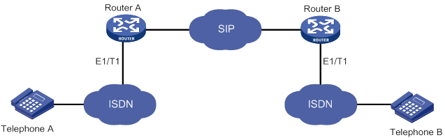
The SIP server might fail to interpret SIP messages carrying QSIG signaling. As a best practice, do not enable QSIG tunneling over SIP-T on a network where the device communicates with the SIP server.
To configure QSIG tunneling over SIP-T:
|
Step |
Command |
Remarks |
|
1. Enter system view. |
system-view |
N/A |
|
2. Enter voice view. |
voice-setup |
N/A |
|
3. Enter dial program view. |
dial-program |
N/A |
|
4. Create a VoIP entity and enter VoIP entity view. |
entity entity-number voip |
N/A |
|
5. Enable QSIG tunneling over SIP-T. |
signaling forward rawmsg |
By default, QSIG tunneling over SIP-T is disabled. If the ISDN network uses overlap sending, the device does not support QSIG tunneling over SIP-T. |
Displaying and maintaining SIP
Execute display commands in any view and reset commands in user view.
|
Task |
Command |
|
Display trusted node list information. |
|
|
Display SIP UA registration status information. |
|
|
Display PSTN cause-to-SIP status mappings. |
|
|
Display SIP calling information. |
|
|
Display information about SIP connections. |
display voice sip connection { tcp | tls } |
|
Disconnect a specific SIP connection. |
reset voice sip connection { tcp | tls } id conn-id |
SIP UA configuration examples
Configuring direct SIP calling
Network requirements
As shown in Figure 36, configure direct SIP calling on Router A and Router B so the phones 1111 and 2222 can call each other.
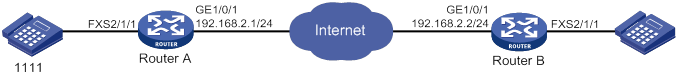
Configuration procedure
1. Configure Router A:
# Assign an IP address to GigabitEthernet 1/0/1.
<RouterA> system-view
[RouterA] interface gigabitethernet 1/0/1
[RouterA-GigabitEthernet1/0/1] ip address 192.168.2.1 255.255.255.0
[RouterA-GigabitEthernet1/0/1] quit
# Set the call destination address to 192.168.2.2, and set the called number to 2222 on VoIP entity 2222.
[RouterA-voice] dial-program
[RouterA-voice-dial] entity 2222 voip
[RouterA-voice-dial-entity2222] address sip ip 192.168.2.2
[RouterA-voice-dial-entity2222] match-template 2222
[RouterA-voice-dial-entity2222] quit
# Bind FXS interface 2/1/1 to POTS entity 1111, and set the local number to 1111 on the POTS entity.
[RouterA-voice-dial] entity 1111 pots
[RouterA-voice-dial-entity1111] line 2/1/1
[RouterA-voice-dial-entity1111] match-template 1111
2. Configure Router B:
# Assign an IP address to GigabitEthernet 1/0/1.
<RouterB> system-view
[RouterB] interface gigabitethernet 1/0/1
[RouterB-GigabitEthernet1/0/1] ip address 192.168.2.2 255.255.255.0
[RouterB-GigabitEthernet1/0/1] quit
# Bind FXS interface 2/1/1 to POTS entity 2222, and set the local number to 2222 on the POTS entity.
[RouterB] voice-setup
[RouterB-voice] dial-program
[RouterB-voice-dial] entity 2222 pots
[RouterB-voice-dial-entity2222] line 2/1/1
[RouterB-voice-dial-entity2222] match-template 2222
[RouterB-voice-dial-entity2222] quit
# Set the call destination address to 192.168.2.1, and set the called number to 1111 on VoIP entity 1111.
[RouterB-voice-dial]entity 1111 voip
[RouterB-voice-dial-entity1111] address sip ip 192.168.2.1
[RouterB-voice-dial-entity1111] match-template 1111
Verifying the configuration
# Place calls to verify that phone 1111 and phone 2222 can call each other.
# Execute the display voice sip call command to display the SIP call information.
Configuring SIP calling through a SIP server
Network requirements
As shown in Figure 37, configure SIP calling through the SIP server on Router A and Router B so the phones 1111 and 2222 can call each other.
On Router A, all phone numbers use the same username routerA and password 1234.
On Router B, phone number 2222 uses the username routerB, password 7890, and domain name server1.
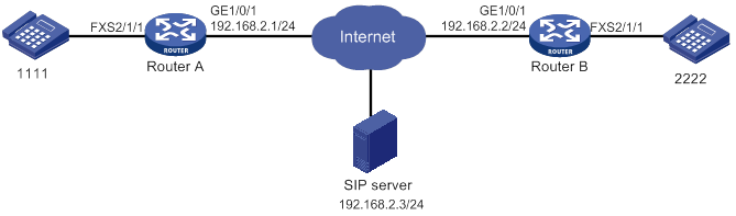
Configuration procedure
1. Configure Router A:
# Assign an IP address to GigabitEthernet 1/0/1.
<RouterA> system-view
[RouterA] interface gigabitethernet 1/0/1
[RouterA-GigabitEthernet1/0/1] ip address 192.168.2.1 255.255.255.0
[RouterA-GigabitEthernet1/0/1] quit
# Specify the SIP registrar and proxy server.
[RouterA-voice] sip
[RouterA-voice-sip] registrar 1 ip 192.168.2.3
[RouterA-voice-sip] proxy ip 192.168.2.3
# Configure global SIP credentials that include username routerA and plaintext password 1234.
[RouterA-voice-sip] user routerA password simple 1234
[RouterA-voice-sip] quit
# Bind FXS interface 2/1/1 to POTS entity 1111, and set the local number to 1111 on the POTS entity.
[RouterA-voice-dial] entity 1111 pots
[RouterA-voice-dial-entity1111] line 2/1/1
[RouterA-voice-dial-entity1111] match-template 1111
[RouterA-voice-dial-entity1111] quit
# Configure VoIP entity 2222 to get the call destination address from the proxy server, and set the called number to 2222 on the VoIP entity.
[RouterA-voice-dial] entity 2222 voip
[RouterA-voice-dial-entity2222] address sip proxy
[RouterA-voice-dial-entity2222] match-template 2222
[RouterA-voice-dial-entity2222] quit
2. Configure Router B:
# Assign an IP address to GigabitEthernet 1/0/1.
<RouterB> system-view
[RouterB] interface gigabitethernet 1/0/1
[RouterB-GigabitEthernet1/0/1] ip address 192.168.2.2 255.255.255.0
[RouterB-GigabitEthernet1/0/1] quit
# Specify the SIP registrar and proxy server.
[RouterB-voice] sip
[RouterB-voice-sip] registrar 1 ip 192.168.2.3
[RouterB-voice-sip] proxy ip 192.168.2.3
[RouterB-voice-sip] quit
# Bind FXS interface 2/1/1 to POTS entity 2222, and set the local number to 2222 on the POTS entity.
[RouterB-voice-dial] entity 2222 pots
[RouterB-voice-dial-entity2222] line 2/1/1
[RouterB-voice-dial-entity2222] match-template 2222
# Configure SIP credentials that include username routerB, plaintext password 7890, and domain name server1 for POTS entity 2222.
[RouterB-voice-dial-entity2222] user routerB password simple 7890 realm server1
# Configure VoIP entity 2222 to get the call destination address from the proxy server, and set the called number to 1111 on the VoIP entity.
[RouterB-voice-dial-entity2222] quit
[RouterB-voice-dial] entity 1111 voip
[RouterB-voice-dial-entity1111] address sip proxy
[RouterB-voice-dial-entity1111] match-template 1111
[RouterB-voice-dial-entity1111] quit
Verifying the configuration
# After the routers register phone numbers on the registrar, place calls to verify that phone 1111 and phone 2222 can call each other through the SIP proxy server. (Details not shown.)
# Execute the display voice sip register-status command to display the registration state for phones 1111 and 2222. (Details not shown.)
# Execute the display voice sip call command to display the SIP call information. (Details not shown.)
Configuring SIP calling through DNS
Network requirements
As shown in Figure 38, configure Router A to get the call destination address through DNS, and configure Router B to use a static call destination address so the phones 1111 and 2222 can call each other.
Configuration procedure
1. Configure Router A:
# Assign an IP address to GigabitEthernet 1/0/1.
<RouterA> system-view
[RouterA] interface gigabitethernet 1/0/1
[RouterA-GigabitEthernet1/0/1] ip address 192.168.2.1 255.255.255.0
[RouterA-GigabitEthernet1/0/1] quit
# Map the IP address 192.168.2.2 to the host name cc.news.com.
[RouterA] ip host cc.news.com 192.168.2.2
# Configure the VoIP entity 2222 to call the destination through domain name cc.news.com, and set the called number to 2222 on the VoIP entity.
[RouterA-voice] dial-program
[RouterA-voice-dial] entity 2222 voip
[RouterA-voice-dial-entity2222] address sip dns cc.news.com port 5060
[RouterA-voice-dial-entity2222] match-template 2222
[RouterA-voice-dial-entity2222] quit
# Bind FXS interface 2/1/1 to POTS entity 1111, and set the local number to 1111 on the POTS entity.
[RouterA-voice-dial] entity 1111 pots
[RouterA-voice-dial-entity1111] line 2/1/1
[RouterA-voice-dial-entity1111] match-template 1111
2. Configure Router B:
# Assign an IP address to GigabitEthernet 1/0/1.
[RouterB] interface gigabitethernet 1/0/1
[RouterB-GigabitEthernet1/0/1] ip address 192.168.2.2 255.255.255.0
[RouterB-GigabitEthernet1/0/1] quit
# Bind FXS interface 2/1/1 to POTS entity 2222, and set the local number to 2222 on the POTS entity.
[RouterB] voice-setup
[RouterB-voice] dial-program
[RouterB-voice-dial] entity 2222 pots
[RouterB-voice-dial-entity2222] line 2/1/1
[RouterB-voice-dial-entity2222] match-template 2222
[RouterB-voice-dial-entity2222] quit
# Set the destination address to 192.168.2.1, and set the called number to 1111 on VoIP entity 1111.
[RouterB-voice-dial]entity 1111 voip
[RouterB-voice-dial-entity1111] address sip ip 192.168.2.1
[RouterB-voice-dial-entity1111] match-template 1111
Verifying the configuration
# Place calls to verify that phone 1111 and phone 2222 can call each other. (Details not shown.)
# Execute the display voice sip call command to display the SIP call information. (Details not shown.)
Configuring SIP to use TCP as the transport protocol
Network requirements
As shown in Figure 39, configure SIP to use TCP as the transport protocol on Router A and Router B, so phone 1111 can call phone 2222 over TCP.
Configuration procedure
1. Configure Router A:
# Assign an IP address to GigabitEthernet 1/0/1.
<RouterA> system-view
[RouterA] interface gigabitethernet 1/0/1
[RouterA-GigabitEthernet1/0/1] ip address 192.168.2.1 255.255.255.0
[RouterA-GigabitEthernet1/0/1] quit
# Configure TCP as the global transport protocol for outgoing SIP calls.
[RouterA-voice] sip
[RouterA-voice-sip] session transport tcp
[RouterA-voice-sip] quit
# Set the destination IP address to 192.168.2.2, and set the called number to 2222 on VoIP entity 2222.
[RouterA-voice-dial] entity 2222 voip
[RouterA-voice-dial-entity2222] address sip ip 192.168.2.2
[RouterA-voice-dial-entity2222] match-template 2222
[RouterA-voice-dial-entity2222] quit
# Bind FXS interface line 2/1/1 to POTS entity 1111, and set the local number to 1111 on the POTS entity.
[RouterA-voice-dial] entity 1111 pots
[RouterA-voice-dial-entity1111] line 2/1/1
[RouterA-voice-dial-entity1111] match-template 1111
2. Configure Router B:
# Assign an IP address to GigabitEthernet 1/0/1.
<RouterB> system-view
[RouterB] interface gigabitethernet 1/0/1
[RouterB-GigabitEthernet1/0/1] ip address 192.168.2.2 255.255.255.0
[RouterB-GigabitEthernet1/0/1] quit
# Enable the TCP listening port. By default, the TCP listening port is enabled.
[RouterB-voice] sip
[RouterB-voice-sip] transport tcp
[RouterB-voice-sip] quit
# Bind FXS interface 2/1/1 to POTS entity 2222, and set the local number to 2222 on the POTS entity.
[RouterB-voice-dial] entity 2222 pots
[RouterB-voice-dial-entity2222] line 2/1/1
[RouterB-voice-dial-entity2222] match-template 2222
# Set the destination address to 192.168.2.1, and set the called number to 1111 on VoIP entity 1111.
[RouterB-voice-dial]entity 1111 voip
[RouterB-voice-dial-entity1111] address sip ip 192.168.2.1
[RouterB-voice-dial-entity1111] match-template 1111
Verifying the configuration
# Place a call to verify that phone 1111 can call phone 2222 over TCP. (Details not shown.)
# Execute the display voice sip connection tcp command to display TCP connection information. (Details not shown.)
Configuring SIP to use TLS as the transport protocol
Network requirements
As shown in Figure 40, configure SIP to use TLS as the transport protocol on Router A and Router B, so phone 1111 can call phone 2222 over TLS.

Configuration procedure
In this example, the CA server runs RSA Keon.
To make sure the certificate on the device is valid, the device system time must be earlier than the expiration time of the certificate.
1. Configure Router A:
# Assign an IP address to GigabitEthernet 1/0/1.
<RouterA> system-view
[RouterA] interface gigabitethernet 1/0/1
[RouterA-GigabitEthernet1/0/1] ip address 192.168.2.1 255.255.255.0
[RouterA-GigabitEthernet1/0/1] quit
# Create a PKI entity named aaa with the common name as RouterA.
[RouterA-pki-entity-aaa] common-name RouterA
[RouterA-pki-entity-aaa] quit
# Create a PKI domain named voice, and specify the name of the trusted CA as voice.
[RouterA-pki-domain-voice] ca identifier voice
# Configure the URL of the registration server in the form of http://host:port/Issuing Jurisdiction ID, where Issuing Jurisdiction ID is a hexadecimal string generated on the CA server.
[RouterA-pki-domain-voice] certificate request url http://192.168.2.88:446/bd0683e5a369eb4edbb4ef502eaca6ec42d24e97
# Specify the CA for accepting certificate requests.
[RouterA-pki-domain-voice] certificate request from ca
# Specify the PKI entity name as aaa, and specify the RSA key pair as keyname and the purpose as general.
[RouterA-pki-domain-voice] certificate request entity aaa
[RouterA-pki-domain-voice] public-key rsa general name keyname
[RouterA-pki-domain-voice] quit
# Generate a local RSA key pair named keyname.
[RouterA] public-key local create rsa name keyname
# Obtain the CA certificate and save it locally.
[RouterA] pki retrieve-certificate domain voice ca
# Submit a certificate request manually.
[RouterA] pki request-certificate domain voice
# Create an SSL server policy, and specify a PKI domain for the SSL server policy.
[RouterA] ssl server-policy server
[RouterA-ssl-server-policy-server] pki-domain voice
# Create an SSL client policy, and specify a PKI domain for the SSL client policy.
[RouterA] ssl client-policy client
[RouterA-ssl-client-policy-client] pki-domain voice
# Specify SSL policies to be used by TLS.
[RouterA-voice] sip
[RouterA-voice-sip] crypto ssl-server-policy server
[RouterA-voice-sip] crypto ssl-client-policy client
# Configure TLS as the global transport protocol for outgoing SIP calls.
[RouterA-voice-sip] session transport tcp tls
# Enable the TLS listening port.
[RouterA-voice-sip] transport tcp tls
[RouterA-voice-sip] quit
# Set the destination IP address and port number to 192.168.2.2 and 5061, and set the called number to 2222 on VoIP entity 2222.
[RouterA-voice-dial] entity 2222 voip
[RouterA-voice-dial-entity2222] address sip ip 192.168.2.2 port 5061
[RouterA-voice-dial-entity2222] match-template 2222
[RouterA-voice-dial-entity2222] quit
# Bind FXS interface 2/1/1 to POTS entity 1111, and set the local number to 1111 on the POTS entity.
[RouterA-voice-dial] entity 1111 pots
[RouterA-voice-dial-entity1111] line 2/1/1
[RouterA-voice-dial-entity1111] match-template 1111
2. Configure Router B:
# Assign an IP address to GigabitEthernet 1/0/1.
<RouterB> system-view
[RouterB] interface gigabitethernet 1/0/1
[RouterB-GigabitEthernet1/0/1] ip address 192.168.2.2 255.255.255.0
[RouterB-GigabitEthernet1/0/1] quit
# Create a PKI entity named aaa with the common name as RouterB.
[RouterB-pki-entity-aaa] common-name RouterB
[RouterB-pki-entity-aaa] quit
# Create a PKI domain named voice, and specify the name of the trusted CA as voice.
[RouterB] pki domain voice
[RouterB-pki-domain-voice] ca identifier voice
# Configure the URL of the registration server in the form of http://host:port/Issuing Jurisdiction ID, where Issuing Jurisdiction ID is a hexadecimal string generated on the CA server.
[RouterB-pki-domain-voice] certificate request url http://192.168.2.88:446/bd0683e5a369eb4edbb4ef502eaca6ec42d24e97
# Specify the CA for accepting certificate requests.
[RouterB-pki-domain-voice] certificate request from ca
# Specify the PKI entity name as voice.
[RouterB-pki-domain-voice] certificate request entity aaa
[RouterB-pki-domain-voice] quit
# Generate a local RSA key pair.
[RouterB] public-key local create rsa
# Obtain the CA certificate and save it locally.
[RouterB] pki retrieve-certificate domain voice ca
# Submit a certificate request manually.
[RouterB] pki request-certificate domain voice
# Create an SSL server policy, and specify a PKI domain for the SSL server policy.
[RouterB] ssl server-policy server
[RouterB-ssl-server-policy-server] pki-domain voice
# Create an SSL client policy, and specify a PKI domain for the SSL client policy.
[RouterB] ssl client-policy client
[RouterB-ssl-client-policy-client] pki-domain voice
# Specify SSL policies to be used by TLS.
[RouterB] voice-setup
[RouterB-voice] sip
[RouterB-voice-sip] crypto ssl-server-policy server
[RouterB-voice-sip] crypto ssl-client-policy client
# Specify TLS as the global transport protocol for outgoing SIP calls.
[RouterB-voice-sip] session transport tcp tls
# Enable the TLS listening port.
[RouterB-voice-sip] transport tcp tls
[RouterB-voice-sip] quit
# Bind FXS interface 2/1/1 to POTS entity 2222, and set the local number to 2222 on the POTS entity.
[RouterB-voice] dial-program
[RouterB-voice-dial] entity 2222 pots
[RouterB-voice-dial-entity2222] line 2/1/1
[RouterB-voice-dial-entity2222] match-template 2222
# Set the destination IP address and port number to 192.168.2.1 and 5061, and set the called number to 1111 on VoIP entity 1111.
[RouterB-voice-dial] entity 1111 voip
[RouterB-voice-dial-entity1111] address sip ip 192.168.2.1 port 5061
[RouterB-voice-dial-entity1111] match-template 1111
Verifying the configuration
# Place calls to verify that phone 1111 and phone 2222 can call each other over TLS. (Details not shown.)
# Execute the display voice sip connection tls command to display TLS connection information. (Details not shown.)
Configuring out-of-band DTMF signaling
Network requirements
As shown in Figure 41, configure Router A and Router B to use out-of-band signaling to transmit DTMF tones so the phones 1111 and 2222 can call each other.
Configuration procedure
1. Configure Router A:
# Assign an IP address to GigabitEthernet 1/0/1.
<RouterA> system-view
[RouterA] interface gigabitethernet 1/0/1
[RouterA-GigabitEthernet1/0/1] ip address 192.168.2.1 255.255.255.0
[RouterA-GigabitEthernet1/0/1] quit
# Set the call destination address to 192.168.2.2, and set the called number to 2222 on VoIP entity 2222.
[RouterA-voice] dial-program
[RouterA-voice-dial] entity 2222 voip
[RouterA-voice-dial-entity2222] address sip ip 192.168.2.2
[RouterA-voice-dial-entity2222] match-template 2222
# Enable out-of-band DTMF signaling for VoIP entity 2222.
[RouterA-voice-dial-entity2222] outband sip
[RouterA-voice-dial-entity2222] quit
# Bind FXS interface 2/1/1 to POTS entity 1111, and set the local number to 1111 on the POTS entity.
[RouterA-voice-dial] entity 1111 pots
[RouterA-voice-dial-entity1111] line 2/1/1
[RouterA-voice-dial-entity1111] match-template 1111
# Enable out-of-band DTMF signaling for POTS entity 1111.
[RouterA-voice-dial-entity1111] outband sip
2. Configure Router B:
# Assign an IP address to GigabitEthernet 1/0/1.
<RouterB> system-view
[RouterB] interface gigabitethernet 1/0/1
[RouterB-GigabitEthernet1/0/1] ip address 192.168.2.2 255.255.255.0
[RouterB-GigabitEthernet1/0/1] quit
# Set the call destination address to 192.168.2.1, and set the called number to 1111 on VoIP entity 1111.
[RouterB-voice] dial-program
[RouterB-voice-dial] entity 1111 voip
[RouterB-voice-dial-entity1111] address sip ip 192.168.2.1
[RouterB-voice-dial-entity1111] match-template 1111
# Enable out-of-band DTMF signaling for VoIP entity 1111.
[RouterB-voice-dial-entity1111] outband sip
[RouterB-voice-dial-entity1111] quit
# Bind FXS interface 2/1/1 to POTS entity 2222, and set the local number to 2222 on the POTS entity.
[RouterB-voice-dial] entity 2222 pots
[RouterB-voice-dial-entity2222] line 2/1/1
[RouterB-voice-dial-entity2222] match-template 2222
# Enable out-of-band DTMF signaling for POTS entity 2222.
[RouterB-voice-dial-entity2222] outband sip
Verify the configuration.
# Place calls to verity that phones 1111 and 2222 can call each other. (Details not shown.)
# Press keys on one phone during a call to verify that DTMF tones are transmitted out of band to the other phone. (Details not shown.)
Configuring SIP trunk
This chapter describes how to configure SIP trunk.
Background
As shown in Figure 42, in a typical telephone network, a PBX forwards internal calls among enterprise phones and forwards outbound calls over a PSTN trunk.
Figure 42 Typical telephone network
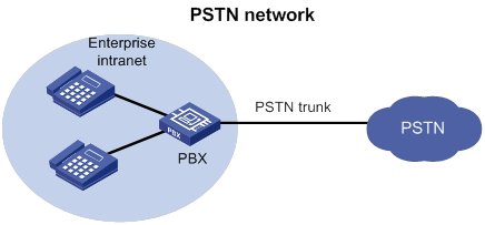
With the development of IP technology, many enterprises deploy SIP-based IP-PBX networks as shown in Figure 43. All internal calls are placed using SIP, and external calls are still placed over a PSTN trunk. The problem is that the enterprises have to maintain both the SIP network and PSTN trunk, which increases the difficulty of network management.
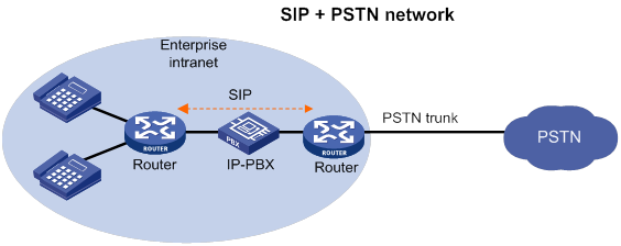
As more enterprise IP-PBX networks run SIP and more Internet Telephone Service Providers (ITSPs) use SIP to provide basic voice communication structures, enterprises urgently need a technology that can connect the enterprise IP-PBX network to the ITSP over SIP. This technology is called SIP trunk. A typical network diagram of SIP trunk is shown in Figure 44.
The SIP trunk feature can be embedded into the voice gateway or the firewall deployed at the edge of an enterprise private network. The device providing the SIP trunk feature is called the SIP trunk device, or the SIP trunk gateway.
Figure 44 All IP-based network
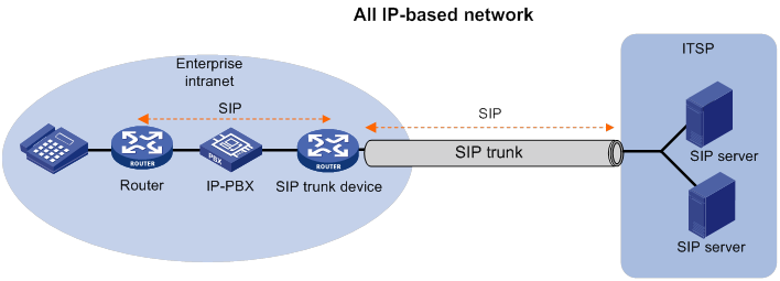
Features
SIP trunk has the following features:
· The SIP trunk device and the ITSP only establish one secure and QoS guaranteed SIP trunk link. The SIP trunk link can carry multiple concurrent calls, and the ITSP only authenticates the link instead of each SIP call carried on this link.
· The enterprise IP-PBX forwards internal calls. The SIP trunk device forwards outbound calls to the ITSP, and then the devices in the ITSP forward the calls to the PSTN. Enterprises do not need to maintain the PSTN trunk, which reduces the costs of hardware and maintenance.
· The enterprise can connect to multiple ITSP by setting destination addresses.
· With the SIP trunk device deployed, the entire network can use SIP to better support IP communication services, such as voice, video conferencing, and instant messaging.
· The SIP trunk device initiates a new call request to the ITSP on behalf of the user after receiving a call request from the user, and both the user and the ITSP communicate only with the SIP trunk device. The SIP trunk device forwards both SIP signaling messages and RTP media messages.
Typical applications
The SIP trunk device is deployed between the enterprise IP-PBX and the ITSP. All internal calls are placed by the enterprise IP-PBX. All outbound calls are forwarded by the SIP trunk device to the ITSP through the SIP trunk link. Figure 45 shows a typical SIP trunk technology.
Figure 45 SIP trunk network diagram
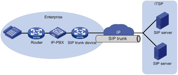
Protocols and standards
· RFC 3261
· RFC 3515
· SIP connect Technical Recommendation v1.1
Feature and hardware compatibility
|
Hardware |
SIP trunk compatibility |
|
MSR810/810-W/810-W-DB/810-LM/810-W-LM/810-10-PoE/810-LM-HK/810-W-LM-HK/810-LMS/810-LUS |
No |
|
MSR2600-6-X1/2600-10-X1 |
Yes |
|
MSR 2630 |
Yes |
|
MSR3600-28/3600-51 |
Yes |
|
MSR3600-28-SI/3600-51-SI |
No |
|
MSR3610-X1/3610-X1-DP/3610-X1-DC/3610-X1-DP-DC |
Yes |
|
MSR 3610/3620/3620-DP/3640/3660 |
Yes |
|
MSR5620/5660/5680 |
Yes (not supported on the router installed with an SPU600-X1 card.) |
|
Hardware |
SIP trunk compatibility |
|
MSR810-LM-GL |
No |
|
MSR810-W-LM-GL |
No |
|
MSR830-6EI-GL |
No |
|
MSR830-10EI-GL |
No |
|
MSR830-6HI-GL |
No |
|
MSR830-10HI-GL |
No |
|
MSR2600-6-X1-GL |
Yes |
|
MSR3600-28-SI-GL |
No |
SIP trunk configuration task list
|
Tasks at a glance |
|
(Required.) Enabling SIP-to-SIP calling |
|
(Required.) Configuring a SIP trunk account |
|
(Optional.) Enabling codec transparent transmission |
|
(Optional.) Enabling media flow-around |
|
(Optional.) Enabling DO-EO conversion |
Enabling SIP-to-SIP calling
After you enable SIP-to-SIP calling, the device works as a SIP trunk device. As a best practice, do not use a SIP trunk device as a SIP UA.
To enable SIP-to-SIP calling:
|
Step |
Command |
Remarks |
|
1. Enter system view. |
system-view |
N/A |
|
2. Enter voice view. |
voice-setup |
N/A |
|
3. Enable SIP-to-SIP calling. |
By default, SIP-to-SIP calling is disabled. |
Configuring a SIP trunk account
A SIP trunk account contains a phone number, credentials, and realms assigned by the service provider. SIP can send a REGISTER request for the phone number to up to six registrars specified by using the registrar command. SIP uses the realm value in 401/407 responses from the registrars to identify the matching credentials. You can configure up to 12 realm values for a phone number, and up to 128 SIP trunk accounts on the device.
To configure a SIP trunk account:
|
Step |
Command |
Remarks |
|
1. Enter system view. |
system-view |
N/A |
|
2. Enter voice view. |
voice-setup |
N/A |
|
3. Enter SIP view. |
N/A |
|
|
4. Create an SIP trunk account. |
credentials number number username username password { cipher | simple } string realm realm |
By default, no SIP trunk accounts exist. |
|
5. Specify a registrar. |
By default, no registrars are specified. |
Enabling codec transparent transmission
If the SIP trunk device does not support any codecs on the calling and called parties, you can enable codec transparent transmission. The SIP trunk device transparently forwards codec capability sets between the two parties without intervening codec negotiation.
To enable codec transparent transmission:
|
Step |
Command |
Remarks |
|
1. Enter system view. |
system-view |
N/A |
|
2. Enter voice view. |
voice-setup |
N/A |
|
3. Enter dial program view. |
dial-program |
N/A |
|
4. Enter VoIP entity view. |
entity entity-number voip |
N/A |
|
5. Enable codec transparent transmission. |
codec transparent |
By default, codec transparent transmission is disabled. |
Enabling media flow-around
This feature enables the SIP trunk device to directly forward media packets between SIP endpoints, without changing the media address for the media packets.
To enable media flow-around:
|
Step |
Command |
Remarks |
|
1. Enter system view. |
system-view |
N/A |
|
2. Enter voice view. |
voice-setup |
N/A |
|
3. Enter dial program view. |
dial-program |
N/A |
|
4. Enter VoIP entity view. |
entity entity-number voip |
N/A |
|
5. Enable media flow-around. |
media flow-around |
By default, the SIP trunk device changes the media address of a media packet to its own address before forwarding the media packet. |
Enabling DO-EO conversion
An INVITE request with SDP Offer is an early offer, and an INVITE request without SDP Offer is a delayed offer. Some ITSPs mandate early offer calls for charge security. To meet this requirement, enable delayed offer to early offer (DO-EO) conversion on the SIP trunk device.
To enable DO-EO conversion:
|
Step |
Command |
Remarks |
|
1. Enter system view. |
system-view |
N/A |
|
2. Enter voice view. |
voice-setup |
N/A |
|
3. Enter dial program view. |
dial-program |
N/A |
|
4. Enter VoIP entity view. |
entity entity-number voip |
N/A |
|
5. Enable DO-EO conversion. |
By default, DO-EO conversion is disabled. This command does not take effect if codec transparent transmission or media flow-around is enabled. |
Displaying and maintaining SIP trunk
Execute display commands in any view.
|
Task |
Command |
|
Display SIP trunk account registration status information. |
SIP trunk configuration examples
Network requirements
As shown in Figure 46, configure the SIP trunk device to forward calls between the private network and public network.
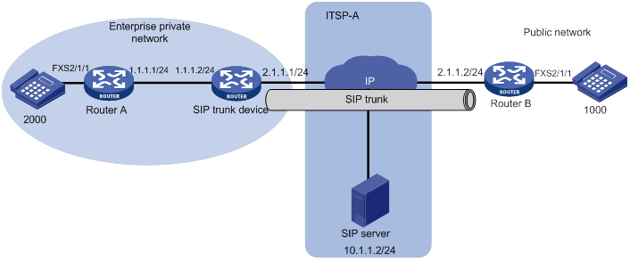
Configuration procedure
1. Configure Router A:
# Set the local number to 2000 on POTS entity 2000.
<RouterA> system-view
[RouterA] voice-setup
[RouterA-voice] dial-program
[RouterA-voice-dial] entity 2000 pots
[RouterA-voice-dial-entity2000] line 2/1/1
[RouterA-voice-dial-entity2000] match-template 2000
[RouterA-voice-dial-entity2000] quit
# Set the called number to 1000, and the destination IP address to 1.1.1.2 (the address of the interface on the SIP trunk device) on VoIP entity 1000.
[RouterA-voice-dial] entity 1000 voip
[RouterA-voice-dial-entity1000] address sip ip 1.1.1.2
[RouterA-voice-dial-entity1000] match-template 1000
2. Configure the SIP trunk device:
# Enable SIP-to-SIP calling.
[TG] voice-setup
[TG-voice] allow-connections sip to sip
[TG-voice] sip
# Create a SIP trunk account for phone number 2000 that uses username 2000 and password 2000 in realm abc.
[TG-voice-sip] credentials number 2000 username 2000 password simple 2000 realm abc
# Specify the registrar 10.1.1.2 for the SIP trunk account.
[TG-voice-sip] registrar 1 ip 10.1.1.2
[TG-voice-sip] quit
# Set the destination address to 2.1.1.2 for outbound calls from private phone 2000 to public phone 1000.
[TG-voice-dial] entity 1 voip
[TG-voice-dial-entity1] address sip ip 2.1.1.2
[TG-voice-dial-entity1] match-template 1000
[TG-voice-dial-entity1] quit
# Set the destination address to 1.1.1.1 for inbound calls from public phone 1000 to private phone 2000.
[TG-voice-dial-entity2] address sip ip 1.1.1.1
[TG-voice-dial-entity2] match-template 2000
3. Configure Router B:
# Bind FXS interface 2/1/1 to POTS entity 1000, and set the local number to 1000 on the POTS entity.
<RouterB> system-view
[RouterB] voice-setup
[RouterB-voice] dial-program
[RouterB-voice-dial] entity 1000 pots
[RouterB-voice-dial-entity1000] line 2/1/1
[RouterB-voice-dial-entity1000] match-template 1000
[RouterB-voice-dial-entity1000] quit
# Set the called number to 2000, and the destination IP address to 2.1.1.1 (the address of the interface on the SIP trunk device) on VoIP entity 2000.
[RouterB-voice-dial] entity 2000 voip
[RouterB-voice-dial-entity2000] address sip ip 2.1.1.1
[RouterB-voice-dial-entity2000] match-template 2000
4. Verify the configuration:
a. Display SIP trunk account information on the SIP trunk device.
[TG-voice-dial-entity2] display voice sip register-status
Number Entity Registrar Server Expires Status
--------------------------------------------------------------------------------
2000 0 10.1.1.2:5060 1802 Online
The output shows that the private phone number 2000 has registered with the server at 10.1.1.2.
b. Execute the display voice sip call command to verify that all calls between the private network and public network pass through the SIP trunk device. (Details not shown.)
c. On the SIP server of the ITSP, you can view only the interface address of the SIP trunk device, which means that the SIP trunk device can hide the information of private users. (Details not shown.)
Configuring call services
Overview
Call services include call waiting, call hold, call forwarding, call transfer, call backup, MWI, and three-party conference.
Call waiting
Call waiting allows a called party to suspend or end the current call and switch to a new incoming call. For example, subscriber A receives a call from subscriber C while subscriber A is in conversation with subscriber B. Instead of playing busy tones to subscriber C, the system plays ringback tones to subscriber C, and plays waiting tones to subscriber A.
Subscriber A can answer the new call by using either of the following methods:
· Pressing hookflash. In this case, subscriber B is held.
· Hanging up to end the call with subscriber B. In this case, subscriber A is immediately alerted and can pick up the phone to answer the call originated by subscriber C.
Call hold
Call hold allows a called party to place the current call on hold by pressing hookflash and place a new call.
For example, when subscriber A, who is in a conversation with subscriber B, presses hookflash, subscriber B is held (in silent state or listening to waiting tones). The system plays dial tones to subscriber A, waiting for subscriber A to initiate a new call. If subscriber A does not dial any number within a period of time, the system stops playing dial tones, and subscriber A cannot initiate a new call. Subscriber A can resume the call with subscriber B by pressing hookflash again.
Call forwarding
Call forwarding allows a called party to forward a call by notifying the calling party of the forward-to number.
For example, subscriber A calls subscriber B, who is busy, and subscriber B forwards the call to subscriber C. Then, a connection is established between subscriber A and subscriber C. Subscriber B is the initiator of call forwarding, subscriber A is the recipient, and subscriber C is the final recipient.
The system supports the following types of call forwarding:
· Call forwarding unconditional—Forwards an incoming call to the predetermined destination, regardless of the state of the called party.
· Call forwarding busy—Forwards an incoming call to the predetermined destination when the called party is busy.
· Call forwarding no reply—Forwards an incoming call to the predetermined destination when the called party provides no answer within a configurable period of time.
· Call forwarding unavailable—Forwards an incoming call to the predetermined destination when the voice interface of the called party is shut down by executing the shutdown command.
Call transfer
Call transfer allows a subscriber on an active call to connect the other party to a new call.
For example, subscriber A (the originator) and subscriber B (the recipient) are in a conversation. Subscriber A presses hookflash to place the call on hold and dials another number to originate a call to subscriber C (the final recipient). After subscriber A hangs up, the call between subscriber B and subscriber C is established.
Call transfer includes the following types:
· Unattended transfer—The originator hangs up before receiving ringback tones from the final recipient.
· Half-attended transfer—The originator hangs up after receiving ringback tones from the final recipient and before speaking with the final recipient.
· Attended transfer—The originator hangs up after speaking with the final recipient.
During the call transfer process, if the recipient does not support call transfer or the final recipient is busy or provides no reply, the initiator can re-establish the original call.
Call backup
The primary link might be unavailable when the calling party initiates a call through the IP or PSTN network. In this case, if there is a backup link (PSTN link or VoIP link) to the called party, the calling party can reinitiate a call to the called party over the backup link.
MWI
Message Waiting Indication (MWI) notifies a user that there are new messages in the voice mailbox by playing an MWI tone when the user picks up the phone. This feature works with the voice mailbox function of the voice mail server, allowing users to be informed of mailbox status without performing query operations.
The process for MWI is as follows:
1. If a subscriber misses a call, the call is redirected to the voice mailbox.
2. The voice mail server sends a NOTIFY message to notify the SIP UA.
3. The SIP UA notifies the user that there is a change in mailbox status by playing an MWI tone when the user picks up the phone.
Other indication methods such as LED are not supported.
Three-party conference
The process for initiating a three-party conference is as follows:
1. In an active two-party call, one party presses hookflash as the conference initiator and dials a third party to establish a new call.
2. The conference initiator presses hookflash again and then presses 3 to start a three-party conference.
The other two parties are called conference participants.
When the conference initiator hangs up, the three-party conference is released, and all calls are disconnected. When a conference participant hangs up, the other two parties can continue their call.
As shown in Figure 47, a three-party conference is established among Telephone A, Telephone B, and Telephone C. Telephone B is the conference initiator.
The conference initiator can switch between the three-party conference and multiparty call hold service as follows:
3. Presses hookflash and presses 2. Each party restores its state before entering the three-party conference. The call between Telephone B and Telephone A (the other party in the original active call) is held, and the call between Telephone B and Telephone C can continue.
4. Presses hookflash again and presses 3. The three parties re-enter the three-party conference.
A participant of the three-party conference can invite another party to join the conference to implement conference chaining. For example:
5. Telephone C presses hookflash and dials Telephone D.
6. Telephone D goes off-hook.
7. Telephone C presses hookflash again and presses 3.
Telephone A, Telephone B, Telephone C, and Telephone D can speak to each other. Telephone A, Telephone B, and Telephone C can be considered to be in a three-party conference, with Telephone B as the conference initiator. Telephone B, Telephone C, and Telephone D can be considered to be in a three-party conference, with Telephone C as the conference initiator.
When you implement conference chaining, follow these restrictions and guidelines:
· Make sure voice processing modules (VPMs) are installed on the devices of the conference initiators. You can use the display version command to view the installed VPMs.
· Only a conference participant that establishes a call with the initiator over IP can implement conference chaining.
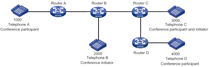
Feature and hardware compatibility
|
Hardware |
Call service compatibility |
|
MSR810/810-W/810-W-DB/810-LM/810-W-LM/810-10-PoE/810-LM-HK/810-W-LM-HK/810-LMS/810-LUS |
No |
|
MSR2600-6-X1/2600-10-X1 |
Yes |
|
MSR 2630 |
Yes |
|
MSR3600-28/3600-51 |
Yes |
|
MSR3600-28-SI/3600-51-SI |
No |
|
MSR3610-X1/3610-X1-DP/3610-X1-DC/3610-X1-DP-DC |
Yes |
|
MSR 3610/3620/3620-DP/3640/3660 |
Yes |
|
MSR5620/5660/5680 |
Yes (not supported on the router installed with an SPU600-X1 card.) |
|
.Hardware |
Call service compatibility |
|
MSR810-LM-GL |
No |
|
MSR810-W-LM-GL |
No |
|
MSR830-6EI-GL |
No |
|
MSR830-10EI-GL |
No |
|
MSR830-6HI-GL |
No |
|
MSR830-10HI-GL |
No |
|
MSR2600-6-X1-GL |
Yes |
|
MSR3600-28-SI-GL |
No |
Call services configuration task list
Call waiting, call hold, call transfer, call backup, and three-party conference are enabled on the device by default. No configurations are required for them.
To configure call services, perform the following tasks:
|
Tasks at a glance |
|
(Optional.) Configuring the call hold mode |
|
(Optional.) Configuring call forwarding |
|
(Optional.) Configuring MWI |
Configuring the call hold mode
There are two call hold modes.
· Silent mode (inactive)—During call hold, the held party hears silence. This mode is configured on the holding party (the initiator of call hold) to signal the held party to close the transmit and receive media channels of the held party.
· Unidirectional playing mode (sendonly)—During call hold, the held party hears tones or music played by a third-party music server. To play tones, configure the sendonly keyword on the holding party to open its transmit media channel and close its receive media channel. To play music on hold by the third-party music server, you must configure the sendonly moh-number string option on the SIP trunk device and configure the inactive keyword on the holding party. For information about configuring a SIP trunk device, see "Configuring SIP trunk."
To configure the call hold mode:
|
Step |
Command |
Remarks |
|
1. Enter system view. |
system-view |
N/A |
|
2. Enter voice view. |
voice-setup |
N/A |
|
3. Configure the call hold mode. |
call-hold-format { inactive | sendonly [ moh-number string ] } |
By default, silent mode is used for call hold. |
Configuring call forwarding
Before configuring call forwarding, make sure there is a route from the initiator to the final recipient.
You must correctly plan forward-to numbers to avoid incorrect numbers and circular calls.
A call can be forwarded a maximum of five times.
To configure call forwarding:
|
Step |
Command |
Remarks |
|
1. Enter system view. |
system-view |
N/A |
|
2. Enter voice view. |
voice-setup |
N/A |
|
3. Enter dial program view. |
dial-program |
N/A |
|
4. Create a POTS entity and enter POTS entity view. |
entity entity-number pots |
N/A |
|
5. Configure call forwarding. |
call-forwarding { no-reply | on-busy | unavailable | unconditional } number number |
By default, call forwarding is disabled. The unconditional, unavailable, on-busy, and no-reply call forwarding types can be configured at the same time and have a descending order of priority. |
Configuring MWI
MWI includes the following types:
· Unsolicited—The SIP UA has subscribed to a voice mail server during registration and can receive NOTIFY messages from the server without sending SUBSCRIBE messages.
· Solicited—The SIP UA needs to subscribe to a voice mail server by sending SUBSCRIBE messages before it can receive NOTIFY messages from the server.
If MWI is configured for one phone number in different voice entities, only the voice entity with the lowest number can successfully subscribe to the voice mail server.
Enabling MWI
A voice entity bound to a voice interface can send SUBSCRIBE messages only after you enable MWI for the voice interface.
To enable MWI:
|
Step |
Command |
Remarks |
|
1. Enter system view. |
system-view |
N/A |
|
2. Enter voice interface view. |
subscriber-line line-number |
N/A |
|
3. Enable MWI. |
mwi |
By default, MWI is disabled. |
Configuring solicited MWI
|
Step |
Command |
Remarks |
|
1. Enter system view. |
system-view |
N/A |
|
2. Enter voice view. |
voice-setup |
N/A |
|
3. Enter SIP view. |
sip |
N/A |
|
4. Specify the voice mail server. |
mwi-server { dns domain-name | ip ip-address } [ port port-number ] [ expires seconds ] [ transport { tcp [ tls ] | udp } ] [ scheme { sip | sips } ] |
By default, no voice mail server is specified. |
Configuring unsolicited MWI
|
Step |
Command |
Remarks |
|
1. Enter system view. |
system-view |
N/A |
|
2. Enter voice view. |
voice-setup |
N/A |
|
3. Enter SIP view. |
sip |
N/A |
|
4. Configure the voice mail server. |
mwi-server { dns domain-name | ip ip-address } [ port port-number ] [ expires seconds ] [ transport { tcp [ tls ] | udp } ] [ scheme { sip | sips } ] unsolicited |
By default, no voice mail server exists. |
|
5. Specify a registrar. |
registrar registrar-index { ip ip-address | dns domain-name } [ port port-number ] [ expires seconds ] [ refresh-ratio ratio-percentage ] |
By default, no registrars are specified. |
Displaying and maintaining MWI
Execute the display commands in any view.
|
Task |
Command |
|
Display MWI information for phone numbers with subscription. |
display voice mwi { all | number number } |
|
Display subscription information for phone numbers. |
display voice sip subscribe-state |
Call services configuration examples
This section provides call services configuration examples.
Call waiting configuration example
Network requirements
As shown in Figure 48, configure call waiting so when a subscriber places a call from Telephone C to Telephone A (that is in a conversation with Telephone B), the subscriber at Telephone C hears ringback tones, and the subscriber at Telephone A hears call waiting tones.
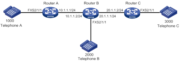
Configuration procedure
Before performing the following configuration, make sure Router A, Router B and Router C can reach each other.
1. Configure Router A:
# Create VoIP entity 2000, configure the destination IP address as 10.1.1.2, and configure the called number as 2000.
<RouterA> system-view
[RouterA] voice-setup
[RouterA-voice] dial-program
[RouterA-voice-dial] entity 2000 voip
[RouterA-voice-dial-entity2000] address sip ip 10.1.1.2
[RouterA-voice-dial-entity2000] match-template 2000
[RouterA-voice-dial-entity2000] quit
# Create VoIP entity 3000, configure the destination IP address as 20.1.1.2, and configure the called number as 3000.
[RouterA-voice-dial] entity 3000 voip
[RouterA-voice-dial-entity3000] address sip ip 20.1.1.2
[RouterA-voice-dial-entity3000] match-template 3000
[RouterA-voice-dial-entity3000] quit
# Configure the local number as 1000 for POTS entity 1000, and bind FXS interface line 2/1/1 to the POTS entity.
[RouterA-voice-dial] entity 1000 pots
[RouterA-voice-dial-entity1000] line 2/1/1
[RouterA-voice-dial-entity1000] match-template 1000
2. Configure Router B:
# Create VoIP entity 1000, configure the destination IP address as 10.1.1.1, and configure the called number as 1000.
<RouterB> system-view
[RouterB] voice-setup
[RouterB-voice] dial-program
[RouterB-voice-dial] entity 1000 voip
[RouterB-voice-dial-entity1000] address sip ip 10.1.1.1
[RouterB-voice-dial-entity1000] match-template 1000
[RouterB-voice-dial-entity1000] quit
# Configure the local number as 2000 for POTS entity 2000, and bind FXS interface line 2/1/1 to the POTS entity.
[RouterB-voice-dial] entity 2000 pots
[RouterB-voice-dial-entity2000] line 2/1/1
[RouterB-voice-dial-entity2000] match-template 2000
3. Configure Router C:
# Configure the local number as 3000 for POTS entity 3000, and bind FXS interface line 2/1/1 to the POTS entity.
<RouterC> system-view
[RouterC] voice-setup
[RouterC-voice] dial-program
[RouterC-voice-dial] entity 3000 pots
[RouterC-voice-dial-entity3000] line 2/1/1
[RouterC-voice-dial-entity3000] match-template 3000
[RouterC-voice-dial-entity3000] quit
# Create VoIP entity 1000, configure the destination IP address as 10.1.1.1, and configure the called number as 1000.
[RouterB-voice-dial] entity 1000 voip
[RouterB-voice-dial-entity1000] address sip ip 10.1.1.1
[RouterB-voice-dial-entity1000] match-template 1000
Verifying the configuration
Operation 1: When the subscriber at Telephone C dials 1000 to call Telephone A that is in a conversation with Telephone B, the subscriber at Telephone C hears ringback tones, and the subscriber at Telephone A hears call waiting tones. If then the subscriber at Telephone A hangs up, Telephone A rings, and the subscriber at Telephone A can pick up the phone to start a conversation with Telephone C.
Operation 2: When the subscriber at Telephone C dials 1000 to call Telephone A that is in a conversation with Telephone B, the subscriber at Telephone A can press hookflash to start a conversation with Telephone C, and Telephone B is held. The subscriber at Telephone A can press hookflash again to continue the talk with Telephone B, and then Telephone C is held.
Call forwarding configuration example
Network requirements
As shown in Figure 49, configure call forwarding on Router B so when a subscriber places a call from Telephone A to Telephone B:
· Router B forwards the call to Telephone C when Telephone B is busy.
· Telephone A can establish a call with Telephone C.
Configuration procedure
Before performing the following configuration, make sure Router A, Router B and Router C can reach each other.
1. Configure Router A:
# Create VoIP entity 2000. Configure the destination IP address as 10.1.1.2, and configure the called number as 2000.
<RouterA> system-view
[RouterA] voice-setup
[RouterA-voice] dial-program
[RouterA-voice-dial] entity 2000 voip
[RouterA-voice-dial-entity2000] address sip ip 10.1.1.2
[RouterA-voice-dial-entity2000] match-template 2000
[RouterA-voice-dial-entity2000] quit
# Configure the local number as 1000 for POTS entity 1000, and bind FXS interface line 2/1/1 to the POTS entity.
[RouterA-voice-dial] entity 1000 pots
[RouterA-voice-dial-entity1000] line 2/1/1
[RouterA-voice-dial-entity1000] match-template 1000
2. Configure Router B:
# Create VoIP entity 3000. Configure the destination IP address as 20.1.1.2, and configure the number template as 3000.
<RouterB> system-view
[RouterB] voice-setup
[RouterB-voice] dial-program
[RouterB-voice-dial] entity 3000 voip
[RouterB-voice-dial-entity3000] address sip ip 20.1.1.2
[RouterB-voice-dial-entity3000] match-template 3000
[RouterB-voice-dial-entity3000] quit
# Configure the local number as 2000 for POTS entity 2000, and bind FXS interface line 2/1/1 to the POTS entity.
[RouterB-voice-dial] entity 2000 pots
[RouterB-voice-dial-entity2000] line 2/1/1
[RouterB-voice-dial-entity2000] match-template 2000
# Configure call forwarding.
[RouterB-voice-dial-entity2000] call-forwarding on-busy number 3000
3. On Router C, configure the local number as 3000 for POTS entity 3000, and bind FXS interface line 2/1/1 to the POTS entity.
<RouterC> system-view
[RouterC] voice-setup
[RouterC-voice] dial-program
[RouterC-voice-dial] entity 3000 pots
[RouterC-voice-dial-entity3000] line 2/1/1
[RouterC-voice-dial-entity3000] match-template 3000
Verifying the configuration
# When Telephone B is busy, place a call from Telephone A to Telephone B to verify that Telephone A can establish a call with Telephone C. (Details not shown.)
Call transfer configuration example
Network requirements
As shown in Figure 50, configure call transfer to achieve the following purpose:
When Telephone A and Telephone B are in a conversation, the subscriber at Telephone A can press hookflash to put the call on hold. Then the subscriber at Telephone A dials 3000 to call Telephone C. After the subscriber at Telephone A hangs up, Telephone B and Telephone C start a conversation.
Configuration procedure
Before performing the following configuration, make sure Router A, Router B and Router C can reach each other.
1. Configure Router A:
# Create VoIP entity 2000. Configure the destination IP address as 10.1.1.2, and configure the called number as 2000.
<RouterA> system-view
[RouterA] voice-setup
[RouterA-voice] dial-program
[RouterA-voice-dial] entity 2000 voip
[RouterA-voice-dial-entity2000] address sip ip 10.1.1.2
[RouterA-voice-dial-entity2000] match-template 2000
[RouterA-voice-dial-entity2000] quit
# Create VoIP entity 3000. Configure the destination IP address as 20.1.1.2, and configure the called number as 3000.
[RouterA-voice-dial] entity 3000 voip
[RouterA-voice-dial-entity3000] address sip ip 20.1.1.2
[RouterA-voice-dial-entity3000] match-template 3000
[RouterA-voice-dial-entity3000] quit
# Configure the local number as 1000 for POTS entity 1000, and bind FXS interface line 2/1/1 to the POTS entity.
[RouterA-voice-dial] entity 1000 pots
[RouterA-voice-dial-entity1000] line 2/1/1
[RouterA-voice-dial-entity1000] match-template 1000
2. On Router B, configure the local number as 2000 for POTS entity 2000, and bind FXS interface line 2/1/1 to the POTS entity.
<RouterB> system-view
[RouterB] voice-setup
[RouterB-voice] dial-program
[RouterB-voice-dial] entity 2000 pots
[RouterB-voice-dial-entity2000] line 2/1/1
[RouterB-voice-dial-entity2000] match-template 2000
3. On Router C, configure the local number as 3000 for POTS entity 3000, and bind FXS interface line 2/1/1 to the POTS entity.
<RouterC> system-view
[RouterC] voice-setup
[RouterC-voice] dial-program
[RouterC-voice-dial] entity 3000 pots
[RouterC-voice-dial-entity3000] line 2/1/1
[RouterC-voice-dial-entity3000] match-template 3000
Verifying the configuration
# Verify that Telephone B and Telephone C can establish a call by using call transfer. (Details not shown.)
Call backup configuration example
Network requirements
As shown in Figure 51, Router A and Router B are connected through two IP links. One of the two links has a higher priority and acts as the primary link. Configure call backup so when the primary link goes down, the backup link can take over.

Configuration procedure
1. Configure Router A:
# Create VoIP entity 2000 with a priority of 1. Configure the destination IP address as 10.1.1.2, and configure the called number as 2000.
<RouterA> system-view
[RouterA] voice-setup
[RouterA-voice] dial-program
[RouterA-voice-dial] entity 2000 voip
[RouterA-voice-dial-entity2000] address sip ip 10.1.1.2
[RouterA-voice-dial-entity2000] match-template 2000
[RouterA-voice-dial-entity2000] priority 1
[RouterA-voice-dial-entity2000] quit
# Create VoIP entity 3000 with a priority of 2. Configure the destination IP address as 20.1.1.2, and configure the called number as 2000.
[RouterA-voice-dial] entity 3000 voip
[RouterA-voice-dial-entity3000] address sip ip 20.1.1.2
[RouterA-voice-dial-entity3000] match-template 2000
[RouterA-voice-dial-entity2000] priority 2
[RouterA-voice-dial-entity3000] quit
# Configure the local number as 1000 for POTS entity 1000, and bind FXS interface line 2/1/1 to the POTS entity.
[RouterA-voice-dial] entity 1000 pots
[RouterA-voice-dial-entity1000] line 2/1/1
[RouterA-voice-dial-entity1000] match-template 1000
2. On Router B, configure the local number as 2000 for POTS entity 2000, and bind FXS interface line 2/1/1 to the POTS entity.
<RouterB> system-view
[RouterB] voice-setup
[RouterB-voice] dial-program
[RouterB-voice-dial] entity 2000 pots
[RouterB-voice-dial-entity2000] line 2/1/1
[RouterB-voice-dial-entity2000] match-template 2000
Verifying the configuration
# When the primary link (corresponding to VoIP entity 2000) fails, place a call from Telephone A to Telephone B to verify that Telephone A can establish a call with Telephone B through the backup link (corresponding to VoIP entity 3000). (Details not shown.)
Three-party conference configuration example
Network requirements
As shown in Figure 52, configure Router A, Router B, and Router C so that Telephone B as the conference initiator can establish a three-party conference with Telephone A and Telephone C.
Configuration procedure
Make sure Router A, Router B, and Router C can reach each other before you configure them.
1. Configure Router A:
# Configure the destination IP address as 10.1.1.2 for VoIP entity 2000, and configure the called number as 2000.
<RouterA> system-view
[RouterA] voice-setup
[RouterA-voice] dial-program
[RouterA-voice-dial] entity 2000 voip
[RouterA-voice-dial-entity2000] address sip ip 10.1.1.2
[RouterA-voice-dial-entity2000] match-template 2000
[RouterA-voice-dial-entity2000] quit
# Configure the local number as 1000 for POTS entity 1000, and bind FXS interface line 2/1/1 to the POTS entity.
[RouterA-voice-dial] entity 1000 pots
[RouterA-voice-dial-entity1000] line 2/1/1
[RouterA-voice-dial-entity1000] match-template 1000
2. Configure Router B:
# Configure the destination IP address as 20.1.1.2 for VoIP entity 3000, and configure the called number as 3000.
[RouterB] voice-setup
[RouterB-voice] dial-program
[RouterB-voice-dial] entity 3000 voip
[RouterB-voice-dial-entity3000] address sip ip 20.1.1.2
[RouterB-voice-dial-entity3000] match-template 3000
[RouterB-voice-dial-entity3000] quit
# Configure the destination IP address as 10.1.1.1 for VoIP entity 1000, and configure the called number as 1000.
[RouterB-voice-dial] entity 1000 voip
[RouterB-voice-dial-entity1000] address sip ip 10.1.1.1
[RouterB-voice-dial-entity1000] match-template 1000
[RouterB-voice-dial-entity1000] quit
# Configure the local number as 2000 for POTS entity 2000, and bind FXS interface line 2/1/1 to the POTS entity.
[RouterB-voice-dial] entity 2000 pots
[RouterB-voice-dial-entity2000] line 2/1/1
[RouterB-voice-dial-entity2000] match-template 2000
3. Configure Router C:
# Configure the local number as 3000 for POTS entity 3000, and bind FXS interface line 2/1/1 to the POTS entity.
[RouterC] voice-setup
[RouterC-voice] dial-program
[RouterC-voice-dial] entity 3000 pots
[RouterC-voice-dial-entity3000] line 2/1/1
[RouterC-voice-dial-entity3000] match-template 3000
[RouterC-voice-dial-entity3000] quit
# Configure the destination IP address as 20.1.1.1 for VoIP entity 2000, and configure the called number as 2000.
[RouterC-voice-dial] entity 2000 voip
[RouterC-voice-dial-entity2000] address sip ip 20.1.1.1
[RouterC-voice-dial-entity2000] match-template 2000
Verifying the configuration
# Verify that Telephone B as the conference initiator can hold a three-party conference with Telephone A and Telephone C. (Details not shown.)
MWI configuration example
Network requirements
As shown in Figure 53, Telephone A and Telephone B are registered with the VCX server (voice mail server) through Router A and Router B, respectively.
Configure voice mailbox access number 9000 for Telephone A on the VCX server. Configure unsolicited MWI on Router A, so that Telephone A can receive MWI messages.
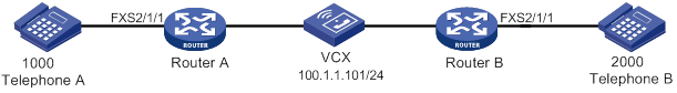
Configuration procedure
1. Configure the VCX server:
? Configure the call processing server:
Open the Web interface of the server and select Central Management Console. Configure the telephone information of Telephone A and Telephone B, with the subscriber passwords as 1000 and 2000, respectively. Figure 54 uses Telephone A as an example.
Figure 54 Configuration page of call processing server (1)
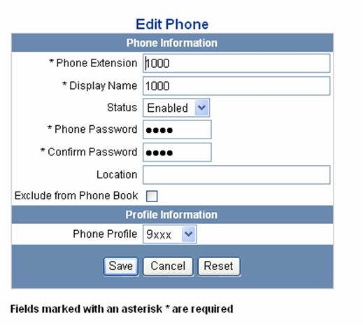
When you access the Edit Phone Profile page, as shown in Figure 55, type 9000 in the Voice Mail Number field.
Figure 55 Configuration page of call processing server (2)
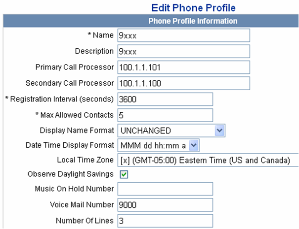
? Configure the unified messaging server:
# Configure the mailbox access number as 9000.
Open the Web interface of the server, select IP Messaging Web Provisioning to log in to the unified messaging server, and click the Configuration link. The Configuration Option box appears, as shown in Figure 56.
Figure 56 Configuration page of unified messaging server
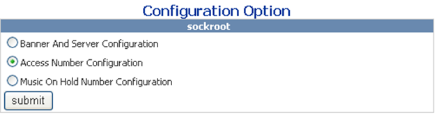
Select 9000 from the Main Voicemail Access Number List, as shown in Figure 57.
Figure 57 Access number configuration page
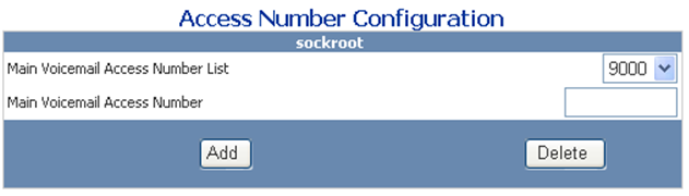
# Configure the voice mailbox of Telephone A
Click the Edit A Mailbox link, enter the mailbox access number 9000 of Telephone A, and then check whether the mailbox is created successfully. If you are prompted that the mailbox is not present, click the Create/Delete Mailboxes link to create the mailbox of Telephone A, with the mailbox number as 9000.
2. Configure Router A:
# Configure VoIP entity 9000 to obtain the destination IP address through the SIP proxy server, and configure the called number as 9000 (mailbox access number) for the VoIP entity. This VoIP entity is used for Telephone A to dial the mailbox access number to log in to the voice mailbox.
<RouterA> system-view
[RouterA] voice-setup
[RouterA-voice] dial-program
[RouterA-voice-dial] entity 9000 voip
[RouterA-voice-dial-entity9000] address sip proxy
[RouterA-voice-dial-entity9000] match-template 9000
[RouterA-voice-dial-entity9000] quit
# Configure the local number as 1000 for POTS entity 1000, and bind FXS interface line 2/1/1 to the POTS entity.
[RouterA-voice-dial] entity 1000 pots
[RouterA-voice-dial-entity1000] line 2/1/1
[RouterA-voice-dial-entity1000] match-template 1000
[RouterA-voice-dial-entity1000] quit
[RouterA-voice-dial] quit
[RouterA] quit
# Enable MWI on FXS interface line 2/1/1.
[RouterA] subscriber-line 2/1/1
[RouterA-subscriber-line1/0] mwi
[RouterA-subscriber-line1/0] quit
# Specify the IP addresses for the proxy server, voice mail server, and registrar.
[RouterA] voice-setup
[RouterA-voice] sip
[RouterA-voice-sip] proxy ip 100.1.1.101
[RouterA-voice-sip] mwi-server ip 100.1.1.101 unsolicited
[RouterA-voice-sip] registrar 1 ip 100.1.1.101
3. Configure Router B:
# Configure VoIP entity 1000 to obtain the destination IP address through the SIP proxy server, and configure the called number as 1000 for the VoIP entity.
<RouterB> system-view
[RouterB] voice-setup
[RouterB-voice] dial-program
[RouterB-voice-dial] entity 1000 voip
[RouterB-voice-dial-entity1000] address sip proxy
[RouterB-voice-dial-entity1000] match-template 1000
[RouterB-voice-dial-entity1000] quit
# Configure the local number as 2000 for POTS entity 2000, and bind FXS interface line 2/1/1 to the POTS entity.
[RouterB-voice-dial] entity 2000 pots
[RouterB-voice-dial-entity2000] line 2/1/1
[RouterB-voice-dial-entity2000] match-template 2000
[RouterB-voice-dial-entity2000] quit
[RouterB-voice-dial] quit
[RouterB-voice] quit
[RouterB-voice] quit
# Specify the IP addresses for the proxy server and registrar.
[RouterB-voice] sip
[RouterB-voice-sip] proxy ip 100.1.1.101
[RouterB-voice-sip] registrar 1 ip 100.1.1.101
Verifying the configuration
# Use the display voice mwi command to verify the MWI setting for phone number 1000.
# Make a call from Telephone B to Telephone A, and do not pick up Telephone A. The call is forwarded to the voice mailbox after the ringing timer expires. Then, the subscriber of Telephone B can leave a message and hang up. The server sends a NOTIFY indicating that there is a new message in the mailbox of Telephone A to the voice gateway. By picking up the phone, the subscriber of Telephone A can hear the MWI tone, and then dial the voice mailbox access number to get the message.
Configuring fax over IP
Fax over IP (FoIP) transmits and receives faxes over the Internet.
Figure 58 FoIP network diagram
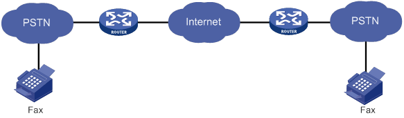
Fax transmission flow
Fax transmission operates in the following phases:
1. Call establishment—The calling terminal sends a Calling Tone (CNG) to identify itself as a fax machine. The called terminal sends a Called Station Identifier (CED) tone to identify itself as a fax machine.
2. Pre-message procedure—The calling or called terminals identify and negotiate the fax capabilities, including the modulation speed.
3. In-message procedure—The calling terminal transmits fax packets in accordance with the T.4 procedure. Packet transmission control functions are performed (including packets synchronization, error detection and correction, and line monitoring).
4. Post-message procedure—The calling or called terminal performs the control operations such as end-of-message signaling, confirmation signaling, and multipage signaling.
5. Call release—Either the calling or called terminal disconnects the call.
Feature and hardware compatibility
|
Hardware |
FoIP compatibility |
|
MSR810/810-W/810-W-DB/810-LM/810-W-LM/810-10-PoE/810-LM-HK/810-W-LM-HK/810-LMS/810-LUS |
No |
|
MSR2600-6-X1/2600-10-X1 |
Yes |
|
MSR 2630 |
Yes |
|
MSR3600-28/3600-51 |
Yes |
|
MSR3600-28-SI/3600-51-SI |
No |
|
MSR3610-X1/3610-X1-DP/3610-X1-DC/3610-X1-DP-DC |
Yes |
|
MSR 3610/3620/3620-DP/3640/3660 |
Yes |
|
MSR5620/5660/5680 |
Yes (not supported on the router installed with an SPU600-X1 card.) |
|
Hardware |
FoIP compatibility |
|
MSR810-LM-GL |
No |
|
MSR810-W-LM-GL |
No |
|
MSR830-6EI-GL |
No |
|
MSR830-10EI-GL |
No |
|
MSR830-6HI-GL |
No |
|
MSR830-10HI-GL |
No |
|
MSR2600-6-X1-GL |
Yes |
|
MSR3600-28-SI-GL |
No |
FoIP configuration task list
|
Tasks at a glance |
|
· (Required.) Configuring the standard T.38 protocol · (Optional.) Enabling CNG fax switchover · (Optional.) Enabling ECM · (Optional.) Configuring an NSF code for nonstandard capabilities negotiation · (Required.) Configuring the maximum fax rate for rate training · (Required.) Configuring a rate training mode · (Required.) Adjusting the transmit energy level |
|
(Required.) Configuring fax pass-through |
|
(Required.) Configuring modem pass-through |
Configuring the fax protocol
Configuring the standard T.38 protocol
The standard T.38 protocol refers to the ITU-T T.38 protocol. It converts T.30-compliant fax signals to T.38 fax packets.
To configure the standard T.38 protocol:
|
Step |
Command |
Remarks |
|
1. Enter system view. |
system-view |
N/A |
|
2. Enter voice view. |
voice-setup |
N/A |
|
3. Enter dial program view. |
dial-program |
N/A |
|
4. Enter voice entity view. |
entity entity-number { pots | voip } |
N/A |
|
5. Configure the standard T.38 protocol. |
fax protocol standard-t38 [ ls-redundancy number [ hs-redundancy number ] ] |
By default, the standard T.38 protocol is used. You only need to configure this command on the calling device, and the called device automatically matches the protocol configured on the calling device. |
Enabling CNG fax switchover
CNG fax switchover enables the device to switch to the fax mode after it receives a CNG from a fax machine.
To enable CNG fax switchover:
|
Step |
Command |
Remarks |
|
1. Enter system view. |
system-view |
N/A |
|
2. Enter voice view. |
voice-setup |
N/A |
|
3. Enter dial program view. |
dial-program |
N/A |
|
4. Enter voice entity view. |
entity entity-number { pots | voip } |
N/A |
|
5. Enable CNG fax switchover. |
fax cng-switch enable |
By default, CNG fax switchover is disabled. |
Enabling ECM
Error Correction Mode (ECM) allows fax machines to transmit fax packets as HDLC frames rather than binary strings and to correct errors. The receiving fax machine requests the sending fax machine to retransmit any HDLC frames it received with errors.
To use ECM, the receiving and sending fax machines must both support ECM.
To enable ECM:
|
Step |
Command |
Remarks |
|
1. Enter system view. |
system-view |
N/A |
|
2. Enter voice view. |
voice-setup |
N/A |
|
3. Enter dial program view. |
dial-program |
N/A |
|
4. Enter voice entity view. |
entity entity-number { pots | voip } |
N/A |
|
5. Enable ECM. |
fax ecm |
By default, ECM is disabled. Use this command on both the calling and called devices. |
Configuring an NSF code for nonstandard capabilities negotiation
Perform this task to match the nonstandard capabilities of the peer fax machine.
In common fax applications, fax machines negotiate with standard capabilities (such as V.17 and V.29) by default and do not send each other nonstandard facilities (NSF) frames. In some cases, such as encrypted fax, the fax machines exchange NSF frames to negotiate nonstandard capabilities.
To configure an NSF code for nonstandard capabilities negotiation:
|
Step |
Command |
Remarks |
|
1. Enter system view. |
system-view |
N/A |
|
2. Enter voice view. |
voice-setup |
N/A |
|
3. Enter dial program view. |
dial-program |
N/A |
|
4. Enter voice entity view. |
entity entity-number { pots | voip } |
N/A |
|
5. Configure an NSF code for nonstandard capabilities negotiation. |
fax nsf value |
By default, the NSF code (2-digit country code plus 4-digit manufacturer code) for nonstandard capabilities negotiation is 264833. The value 000000 specifies standard capabilities negotiation. |
Configuring the maximum fax rate for rate training
When rate training with the configured fax rate fails, the next lower supported rate is used until the rate training succeeds.
If you specify the voice keyword, the maximum fax rate for rate training depends on the codec used.
· If G.711 is used, the maximum fax rate is 14400 bps, and the corresponding modem standard is V.17.
· If G.723.1 Annex A is used, the maximum fax rate is 4800 bps, and the corresponding modem standard is V.27.
· If G.726 is used, the maximum fax rate is 14400 bps, and the corresponding modem standard is V.17.
· If G.729 is used, the maximum fax rate is 7200 bps, and the corresponding modem standard is V.29.
If you specify the disable keyword, the fax function is disabled.
To configure the maximum fax rate for rate training:
|
Step |
Command |
Remarks |
|
1. Enter system view. |
system-view |
N/A |
|
2. Enter voice view. |
voice-setup |
N/A |
|
3. Enter dial program view. |
dial-program |
N/A |
|
4. Enter voice entity view. |
entity entity-number { pots | voip } |
N/A |
|
5. Set the maximum fax rate for rate training. |
fax rate { 2400 | 4800 | 7200 | 9600 | 12000 | 14400 | disable | voice } |
By default, the maximum fax rate for rate training depends on the codec used. |
Configuring a rate training mode
The following training modes are available:
· Local training—The calling and called devices (gateways) participate in the rate training between fax machines.
a. Rate training is performed between the fax machines and their respective gateways.
The fax machine sends a Training Check (TCF) message with a stream of 0s at the maximum fax rate (configured by using the fax rate command) to its gateway. The gateway accepts the rate if the received TCF message contains all 0s or the percentage of the number of 1s to the total bits in the message is less than the set threshold. Otherwise, the fax machine uses the next lower supported rate to send the TCF message for rate retraining until the rate training succeeds.
b. The called device compares the training results and selects the lower rate.
· Point-to-point training—Rate training is performed between two fax machines.
To configure a rate training mode:
|
Step |
Command |
Remarks |
|
1. Enter system view. |
system-view |
N/A |
|
2. Enter voice view. |
voice-setup |
N/A |
|
3. Enter dial program view. |
dial-program |
N/A |
|
4. Enter voice entity view. |
entity entity-number { pots | voip } |
N/A |
|
5. Specify a rate training mode. |
·
(Method 1) Configure point-to-point training: · (Method 2) Configure local training: a. Enable local training: b. Set the threshold value: |
Use either method. By default, point-to-point training is used. |
Adjusting the transmit energy level
Perform this task if you cannot establish fax calls when all other settings are correct.
To adjust the transmit energy level:
|
Step |
Command |
Remarks |
|
1. Enter system view. |
system-view |
N/A |
|
2. Enter voice view. |
voice-setup |
N/A |
|
3. Enter dial program view. |
dial-program |
N/A |
|
4. Enter voice entity view. |
entity entity-number { pots | voip } |
N/A |
|
5. Adjust the transmit energy level. |
fax level level |
The default value is –15 dBm. |
Configuring fax pass-through
Fax pass-through allows fax traffic to be transmitted in RTP packets without being compressed, and it supports G.711alaw and G711ulaw codecs. During fax pass-through, the device automatically disables VAD. Fax pass-through features low delay but is susceptible to packet loss and jitter.
To configure fax pass-through:
|
Step |
Command |
Remarks |
|
1. Enter system view. |
system-view |
N/A |
|
2. Enter voice view. |
voice-setup |
N/A |
|
3. Enter dial program view. |
dial-program |
N/A |
|
4. Enter voice entity view. |
entity entity-number { pots | voip } |
N/A |
|
5. Enable fax pass-through. |
fax protocol pass-through { g711alaw | g711ulaw } |
By default, the standard T.38 protocol is used. You only need to configure this command on the calling device, and the called device automatically matches the configured protocol. |
Configuring modem pass-through
Modem pass-through allows modem signals to be transmitted in RTP packets without being compressed, and it supports G.711alaw and G711ulaw codecs. During modem pass-through, the device automatically disables VAD.
To configure modem pass-through:
|
Step |
Command |
Remarks |
|
1. Enter system view. |
system-view |
N/A |
|
2. Enter voice view. |
voice-setup |
N/A |
|
3. Enter dial program view. |
dial-program |
N/A |
|
4. Enter voice entity view. |
entity entity-number { pots | voip } |
N/A |
|
5. Configure modem pass-through. |
modem passthrough { nse [ payload-type number ] | protocol } codec { g711alaw | g711ulaw } |
By default, modem pass-through is not used. |
FoIP configuration examples
Configuring FoIP
Network requirements
As shown in Figure 59, configure Router A and Router B to use the standard T.38 protocol for fax transmission.

Configuration procedure
# Configure the called fax number as 2000 for VoIP entity 2000, and configure the destination IP address as 2.2.2.2.
[RouterA] voice-setup
[RouterA-voice] dial-program
[RouterA-voice-dial] entity 2000 voip
[RouterA-voice-dial-entity2000] match-template 2000
[RouterA-voice-dial-entity2000] address sip ip 2.2.2.2
# Configure the standard T.38 protocol for VoIP entity 2000, with a low redundancy value of 4.
[RouterA-voice-dial-entity2000] fax protocol standard-t38 ls-redundancy 4
[RouterA-voice-dial-entity2000] quit
# Configure the local fax number as 1000 for POTS entity 1000, and bind FXS interface line 2/1/1 to the POTS entity.
[RouterA-voice-dial] entity 1000 pots
[RouterA-voice-dial-entity1000] match-template 1000
[RouterA-voice-dial-entity1000] line 2/1/1
# Configure the standard T.38 protocol for POTS entity 1000, with a low redundancy value of 4.
[RouterA-voice-dial-entity1000] fax protocol standard-t38 ls-redundancy 4
# Configure the called fax number as 1000 for VoIP entity 1000, and configure the destination IP address as 1.1.1.1.
[RouterB] voice-setup
[RouterB-voice] dial-program
[RouterB-voice-dial] entity 1000 voip
[RouterB-voice-dial-entity1000] match-template 1000
[RouterB-voice-dial-entity1000] address sip ip 1.1.1.1
# Configure the standard T.38 protocol for VoIP entity 1000, with a low redundancy value of 4.
[RouterB-voice-dial-entity1000] fax protocol standard-t38 ls-redundancy 4
[RouterB-voice-dial-entity1000] quit
# Configure the local fax number as 2000 for POTS entity 2000, and bind FXS interface line 2/1/1 to the POTS entity.
[RouterB-voice-dial] entity 2000 pots
[RouterB-voice-dial-entity2000] match-template 2000
[RouterB-voice-dial-entity2000] line 2/1/1
# Configure the standard T.38 protocol for POTS entity 2000, with a low redundancy value of 4.
[RouterB-voice-dial-entity2000] fax protocol standard-t38 ls-redundancy 4
Configuring modem pass-through
Network requirements
As shown in Figure 60, configure modem pass-through on Router A and Router B for data communication between PC 1 and PC 2.
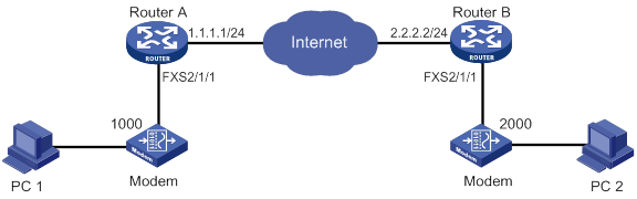
Configuration procedure
1. Configure Router A:
# Configure the called number as 2000 for VoIP entity 2000, and configure the destination IP address as 2.2.2.2.
<RouterA> system-view
[RouterA] voice-setup
[RouterA-voice] dial-program
[RouterA-voice-dial] entity 2000 voip
[RouterA-voice-dial-entity2000] match-template 2000
[RouterA-voice-dial-entity2000] address sip ip 2.2.2.2
# Configure modem pass-through for VoIP entity 2000.
[RouterA-voice-dial-entity2000] modem passthrough protocol codec g711alaw
[RouterA-voice-dial-entity2000] quit
# Configure the local number as 1000 for POTS entity 1000, and bind FXS interface line 2/1/1 to the POTS entity.
[RouterA-voice-dial] entity 1000 pots
[RouterA-voice-dial-entity1000] match-template 1000
[RouterA-voice-dial-entity1000] line 2/1/1
# Configure modem pass-through for POTS entity 1000.
[RouterA-voice-dial-entity1000] modem passthrough protocol codec g711alaw
2. Configure Router B:
# Configure the called number as 1000 for VoIP entity 1000, and configure the destination IP address as 1.1.1.1.
<RouterB> system-view
[RouterB] voice-setup
[RouterB-voice] dial-program
[RouterB-voice-dial] entity 1000 voip
[RouterB-voice-dial-entity1000] match-template 1000
[RouterB-voice-dial-entity1000] address sip ip 1.1.1.1
# Configure modem pass-through for VoIP entity 1000.
[RouterB-voice-dial-entity1000] modem passthrough protocol codec g711alaw
[RouterB-voice-dial-entity1000] quit
# Configure the local number as 2000 for POTS entity 2000, and bind FXS interface line 2/1/1 to the POTS entity.
[RouterB-voice-dial] entity 2000 pots
[RouterB-voice-dial-entity2000] match-template 2000
[RouterB-voice-dial-entity2000] line 2/1/1
# Configure modem pass-through for POTS entity 2000.
[RouterB-voice-dial-entity2000] modem passthrough protocol codec g711alaw
Configuring SRST
Overview
Survivable Remote Site Telephony (SRST) provides backup call management when the WAN connection goes down or the primary voice server fails.
As shown in Figure 61, the Alone server in the headquarters is the remote primary voice server. Alive server A and Alive server B in the branches are local survivable voice servers. Typically, the Alone server manages calls from and to branch office IP phones. When the WAN connection or the Alone server goes down, IP phones are connected to the PSTN network through survivable servers. Alive server A and Alive server B take over call management, and IP phones can place and receive calls. When the WAN link or the connection to the Alone server is restored, call handling reverts back to the Alone server.
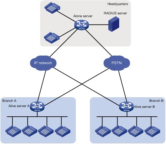
Operating modes
A voice server can operate in the following modes:
· Standalone mode—A voice server that operates in standalone mode provides call management services.
· Survivable mode—A voice server that operates in survivable mode provides backup call management services when the standalone voice server fails or the WAN connection goes down.
In this document, an Alone server refers to a standalone voice server, and an Alive server refers to a survivable voice server.
SIP registrar
Voice servers can act as SIP registrars, and SIP UAs are required to register with them. During SIP UA registration, standalone voice servers can challenge and authenticate SIP UAs, but survivable voice servers cannot.
As shown in Figure 62, IP phone A and IP phone B register with both the Alive server and the Alone server. The Alone server authenticates the two IP phones.
Figure 62 Registration process
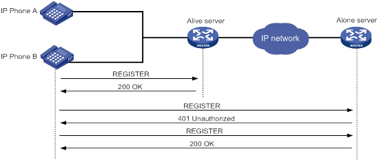
For more information about SIP registration, see "Configuring SIP."
VoIP entities in SRST
SRST introduces dynamic VoIP entities and distinguishes incoming and outgoing VoIP entities.
Dynamic VoIP entities
Dynamic VoIP entities are automatically created by the system.
Based on registration status, dynamic VoIP entities include the following types:
· Registered dynamic VoIP entity—Created after a SIP UA successfully registers with the standalone voice server and the survivable voice server.
On the survivable voice server, two dynamic VoIP entities are created, and the call destinations are the SIP UA and the standalone voice server. On the standalone voice server, only one dynamic incoming VoIP entity is created, and the call destination is the SIP UA.
· Unregistered dynamic VoIP entity—Created after call forwarding is configured in directory numbers (DNs) for SIP UAs that do not register with the voice server.
For more information about call forwarding, see "Configuring call forwarding." For more information about DNs, see "Configuring DNs."
When a call arrives, the voice server first looks up a matching dynamic VoIP entity. If no match is found, it looks up a matching static VoIP entity according to the configured entity selection order. For more information about entity selection orders, see "Configuring dial programs."
Incoming and outgoing VoIP entities
Based on call direction, VoIP entities include the following types:
· Incoming VoIP entity—Matches an incoming call. An incoming VoIP entity maintains registration credentials and call attributes. Only calls whose calling number and call destination match an incoming VoIP entity can be placed.
· Outgoing VoIP entity—Matches an outgoing call. An outgoing VoIP entity maintains the called information such as called number and call destination.
Keepalive feature
The keepalive feature enables a local survivable voice server to check the availability of a remote standalone voice server by sending OPTIONS messages.
Figure 63 describes the keepalive process:
1. The Alive server periodically sends an OPTIONS message to the Alone server.
2. If the Alone server is available, it replies with a 200 OK response.
If the Alone server is not available, the Alive server receives an error response or does not receive a response in the specified time. In this case, the Alive server takes over to manage calls for the local site.
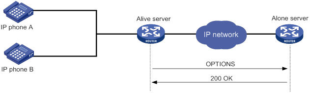
PSTN backup
The local survivable voice server can use the PSTN as a fallback when the WAN link goes down. If POTS entities exist, the following calls can be established over the PSTN network:
· Calls within a branch.
· Calls between different branches.
· Calls between a branch and the headquarters.
For more information about configuring POTS entities for PSTN backup, see "PSTN backup configuration example."
Basic call flow
As shown in Figure 64, IP phone A and IP phone B successfully register with Alive server A and the Alone server. IP phones C and D successfully register with Alive server B and the Alone server.
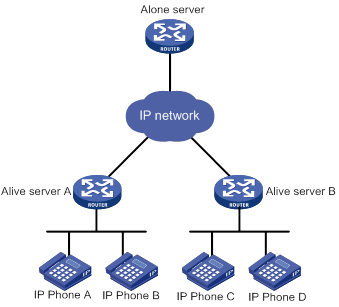
Call flow for basic calls within a branch
The following shows the call flow from IP phone A to IP phone B:
· Alive server A is the call destination on IP phone A:
a. IP phone A places a call to IP phone C.
b. The call arrives at Alive server A. Alive server A uses the matching static VoIP entity to forward the call to the Alone server. In the static VoIP entity, the called number is IP phone C and the call destination is the Alone server.
c. The call arrives at Alone server. The Alone server uses the matching VoIP entity to forward the call to IP phone B. In the VoIP entity, the call destination is IP phone B.
d. IP phone B receives the call.
· The Alone server is the call destination on IP phone A:
e. IP phone A places a call to IP phone B.
f. The call arrives at the Alone server. The Alone server uses the matching dynamic VoIP entity to forward the call to IP phone B. In the dynamic VoIP entity, the call destination is IP phone B.
g. IP phone B receives the call.
Call flow for basic calls between different branches
The following shows the call flow from IP phone A to IP phone C:
· Alive server A is the call destination on IP phone A:
a. IP phone A places a call to IP phone C.
b. The call arrives at Alive server A. Alive server A uses the matching static VoIP entity to forward the call to Alone server. In the static VoIP entity, the called number is IP phone C and the call destination is Alone server.
c. The call arrives at the Alone server. The Alone server uses the matching dynamic VoIP entity to forward the call to IP phone C. In the dynamic VoIP entity, the call destination is IP phone C.
d. IP phone C receives the call.
· The Alone server is the call destination on IP phone A:
e. IP phone A places a call to IP phone C.
f. The call arrives at the Alone server. The Alone server uses the matching dynamic VoIP entity to forward the call to IP phone C. In the dynamic VoIP entity, the call destination is IP phone C.
g. IP phone C receives the call.
Call services supported by SRST
SRST supports the following call services:
· Call blocking.
· Call forwarding.
· Do Not Disturb (DND).
· Feature Access Codes (FACs).
· Music On Hold (Music On Hold).
· MWI.
Feature and hardware compatibility
|
Hardware |
SRST compatibility |
|
MSR810/810-W/810-W-DB/810-LM/810-W-LM/810-10-PoE/810-LM-HK/810-W-LM-HK/810-LMS/810-LUS |
No |
|
MSR2600-6-X1/2600-10-X1 |
Yes |
|
MSR 2630 |
Yes |
|
MSR3600-28/3600-51 |
Yes |
|
MSR3600-28-SI/3600-51-SI |
No |
|
MSR3610-X1/3610-X1-DP/3610-X1-DC/3610-X1-DP-DC |
Yes |
|
MSR 3610/3620/3620-DP/3640/3660 |
Yes |
|
MSR5620/5660/5680 |
Yes (not supported on the router installed with an SPU600-X1 card.) |
|
Hardware |
SRST compatibility |
|
MSR810-LM-GL |
No |
|
MSR810-W-LM-GL |
No |
|
MSR830-6EI-GL |
No |
|
MSR830-10EI-GL |
No |
|
MSR830-6HI-GL |
No |
|
MSR830-10HI-GL |
No |
|
MSR2600-6-X1-GL |
Yes |
|
MSR3600-28-SI-GL |
No |
SRST configuration task list
|
Tasks at a glance |
|
(Required.) Configuring a voice server: · (Required.) Specifying an operating mode · (Required.) Configuring the SIP registrar · (Required.) Configuring SIP registration parameters · (Required.) Configuring register pools · (Required.) Configuring DNs · (Required.) Configuring the keepalive feature |
|
(Required.) Configuring basic calling |
|
Configuring call services supported by SRST: · (Optional.) Configuring MOH · (Optional.) Configuring solicited MWI · (Optional.) Configuring call pickup · (Optional.) Enabling DND · (Optional.) Configuring call forwarding · (Optional.) Configuring call blocking · (Optional.) Configuring FACs |
Configuring a voice server
Specifying an operating mode
By default, a device is not a voice server. For a device to act as a voice server, you must specify an operating mode. The configurations for a voice server vary by operating mode.
To specify an operating mode:
|
Step |
Command |
Remarks |
|
1. Enter system view. |
system-view |
N/A |
|
2. Enter voice view. |
voice-setup |
N/A |
|
3. Create a global register pool and enter its view. |
voice register global |
By default, no global register pool exists. |
|
4. Specify an operating mode. |
By default, the device does not act as a voice server. |
Configuring the SIP registrar
By default, a SIP voice gateway or SIP trunk cannot process SIP register messages. For a device to process SIP register messages, configure the device as the SIP registrar.
To configure the SIP registrar:
|
Step |
Command |
Remarks |
|
1. Enter system view. |
N/A |
|
|
2. Enter voice view. |
N/A |
|
|
3. Enter SIP view. |
N/A |
|
|
4. Enable the SIP registrar and optionally set the global registration expiration time. |
By default, the SIP registrar is disabled. |
Configuring SIP registration parameters
For the voice server to successfully accept SIP UA registration, you must set the maximum number of register pools and DNs to a non-zero value.
To allow a standalone voice server to authenticate SIP UAs, enable SIP register authentication on the server and configure credentials for authentication.
SIP register authentication is supported only on standalone voice servers.
To configure registration parameters:
|
Step |
Command |
Remarks |
|
1. Enter system view. |
N/A |
|
|
2. Enter voice view. |
N/A |
|
|
3. Create a global register pool and enter its view. |
By default, no global register pool exists. |
|
|
4. Set the maximum number of register pools. |
By default, the maximum number of register pools is 0. |
|
|
5. Set the maximum number of DNs. |
max-dn max-dn |
By default, the maximum number of DNs is 0. |
|
6. (Optional.) Enable SIP register authentication. |
authenticate register |
By default, SIP register authentication is disabled. This command does not take effect on a survivable voice server. |
|
7. (Optional.) Configure the realm name carried in 401 responses. |
authenticate realm string |
By default, no realm name is carried in 401 responses. This command does not take effect on a survivable voice server. |
|
8. (Optional.) Configure credentials. |
username username password { cipher | simple } string |
By default, no credentials exist. This command does not take effect on a survivable voice server. |
Configuring register pools
A register pool contains registration requirements that define which SIP UAs can register and also maintains registration information of SIP UAs. If a SIP UA meets the registration requirements of a register pool on a voice server, it successfully registers with the voice server. Then, a dynamic VoIP entity is created, and it inherits configurations in the register pool.
If multiple register pools exist, a SIP UA matches registration requirements in register pools in the ascending order of their tags. If multiple register number templates exist in a register pool, the SIP UA matches these templates in the ascending order of their tags.
Configuration guidelines
When you configure register pools, follow these restrictions and guidelines:
· If you configure both the number and id commands for a register pool, only SIP UAs with matching phone numbers and addresses successfully register.
· SIP UAs can register with a voice server only by its own address, number, or both but not by the realm name of the voice server.
· As a best practice, do not configure the voice server to process registration based on a MAC address if SIP UAs use TCP or TLS to transmit register messages.
Configuration procedure
To configure register pools:
|
Step |
Command |
Remarks |
|
1. Enter system view. |
N/A |
|
|
2. Enter voice view. |
N/A |
|
|
3. Create a register pool and enter its view. |
By default, no register pools exist. |
|
|
4. Configure registration requirements for SIP UAs. |
·
Method 1: ·
Method 2: |
Use either method or both of them. By default, no registration requirements exist and any SIP UAs can register. |
|
5. (Optional.) Set the registration expiration time. |
By default, the global registration expiration time applies. |
|
|
6. (Optional.) Set the priority for dynamic VoIP entities in the register pool. |
By default, the priority is 0. The lower the value, the higher the priority. |
|
|
7. (Optional.) Enable out-of-band DTMF. |
By default, inband DTMF is used. |
|
|
8. (Optional.) Apply a number substitution rule list to the register pool. |
By default, no number substitution rule is applied to a register pool, and number substitution is not performed. |
|
|
9. (Optional.) Apply a codec template to the register pool |
By default, no codec template is applied to the register pool. |
|
|
10. (Optional.) Bind a subscriber group to the register pool to permit or deny calls from numbers in the subscriber group. |
By default, no subscriber group is bound to the register pool. |
Configuring DNs
DNs allow you to make configurations specific to SIP UAs with matching phone numbers. Dynamic VoIP entities created for these numbers inherit the configurations in the DN rather than those in the register pool where VoIP entities are created.
For example, dynamic VoIP entities are created for IP phones on the subnet 10.1.1.0 in a register pool. The priority of the dynamic VoIP entities in the register pool is 3. To change the priority of dynamic VoIP entity to 1 for the phone with number 1000, perform the following tasks:
1. Create a DN.
2. Set the register number template for the DN to 1000.
3. Set the priority of dynamic VoIP entities in the DN to 1.
4. Apply the DN to the register pool.
Configuration guidelines
When you configure DNs, follow these restrictions and guidelines:
· You can configure only one register number template for a DN.
· All successfully registered numbers end with a dollar sign ($) in the command output. You can use the display voice register entity command and the display voice register pool all brief command to view numbers that are successfully registered.
Configuration procedure
To configure DNs:
|
Step |
Command |
Remarks |
|
1. Enter system view. |
N/A |
|
|
2. Enter voice view. |
N/A |
|
|
3. Create a DN and enter its view. |
By default, no DNs exist. |
|
|
4. Configure a register number template for the DN. |
By default, no register number template is configured for a DN. |
|
|
5. Set the priority for dynamic VoIP entities in the DN. |
By default, the priority is 0. The lower the value, the higher the priority. |
Configuring the keepalive feature
For a survivable voice server to regularly check the availability of the standalone voice server, you must configure the keepalive feature.
Configuration guidelines
When you configure the keepalive feature, follow these restrictions and guidelines:
· This feature is supported only on survivable voice servers.
· When multiple SIP UAs that have the same number have successfully registered with a remote voice server, the following VoIP entities are created:
? Multiple dynamic VoIP entities of which the call destinations are the SIP UAs.
? Only one dynamic VoIP entity of which the call destination is the remote voice server. This entity is not deleted until all the SIP UAs deregister from the remote voice server.
Configuration procedure
To configure the keepalive feature:
|
Step |
Command |
Remarks |
|
1. Enter system view. |
system-view |
N/A |
|
2. Enter voice view. |
voice-setup |
N/A |
|
3. Create a register pool and enter its view. |
voice register pool pool-tag |
By default, no register pools exist. |
|
4. Specify remote voice servers and enable the keepalive feature. |
proxy ip ip1 [ port main-port-number ] [ monitor probe sip [ ip2 [ port backup-port-number ] ] ] [ priority priority ] |
By default, no remote voice severs exist. |
|
5. Set keepalive parameters. |
voice-class sip options-keepalive [ up-interval interval ] [ down-interval interval ] [ retry retries ] |
By default, the up-interval is 60 seconds, the down-interval is 30 seconds, and the retry is 5 times. |
Configuring basic calling
For a voice server to provide basic call services, you must complete the following tasks:
· Enable SIP-to-SIP calling by using the allow-connections sip to sip command.
· Configure VoIP entities that can forward calls to terminating devices.
· Configure call attributes for VoIP entities to match incoming calls.
Configuring call services supported by SRST
Configuring MOH
MOH is a music stream that is played to an IP phone user who is placed on hold. To save bandwidth, you can configure local voice servers as MOH resources to provide MOH. This eliminates the need to transmit MOH across a WAN.
You can configure the local voice server to unicast or multicast MOH streams. For more information about unicasting MOH streams, see "Configuring call services". The following example shows the process of multicasting MOH streams.
As shown in Figure 65, IP phone A and the Alone server (the local voice server) belong to a branch. The call management server and the Alone server are configured with the MOH multicast address 239.1.1.2 and port 2009.
Figure 65 Voice server as the MOH multicast resource
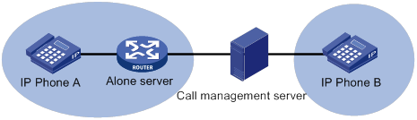
MOH is multicast as follows:
1. IP phone B holds the call from IP phone A.
2. The call management server receives the Re-Invite message for call hold from IP phone B. It sends the MOH multicast address and port number to IP phone A that is being held.
3. IP phone A joins the multicast group and receives the MOH stream.
To configure MOH:
|
Step |
Command |
Remarks |
|
1. Enter system view. |
system-view |
N/A |
|
2. Enter voice view. |
voice-setup |
N/A |
|
3. Enter the global register pool view. |
voice register global |
N/A |
|
4. Configure MOH. |
·
Configure the device to multicast MOH: ·
Configure the device to unicast MOH: |
If you configure both commands, the MOH streaming mode on the call management server applies. By default, no MOH multicast address is configured, and the call hold mode is inactive. |
|
5. Specify an MOH resource file. |
By default, no MOH resource file exists. |
Configuring solicited MWI
When you configure MWI on the device, registered numbers in a DN can subscribe to the MWI service.
For more information about MWI, see "Configuring call services."
To configure solicited MWI:
|
Step |
Command |
Remarks |
|
1. Enter system view. |
system-view |
N/A |
|
2. Enter voice view. |
voice-setup |
N/A |
|
3. Enter SIP view. |
sip |
N/A |
|
4. Configure the voice mail server. |
mwi-server { dns domain-name | ip ip-address } [ port port-number ] [ expires seconds ] [ transport { tcp [ tls ] | udp } ] [ scheme { sip | sips } ] |
By default, no voice mail server exists. A voice mail server does not support unsolicited MWI. |
|
5. Return to voice view. |
quit |
N/A |
|
6. Create a DN and enter DN view. |
voice register dn dn-tag |
By default, no DNs exist. |
|
7. Enable MWI for the DN. |
mwi |
By default, MWI is disabled for a DN. |
Configuring call pickup
Call pickup allows users to answer a call on their own phones when the call is destined for another phone.
Call pickup includes the following types:
· Direct call pickup—Allows users to answer any calls by pressing the GPickUp softkey and dialing the called numbers.
· Local group pickup—Allows users to answer calls within their own pickup group by using either of the following methods:
? Press the PickUp softkey.
? Press the GPickUp softkey and the asterisk (*) key.
· Group pickup—Allows users to answer calls for other pickup groups by pressing the GPickUp softkey and dialing the pickup group numbers. If called numbers do not belong to any pickup groups, users can answer calls by pressing the GPickUp softkey and the asterisk (*) key.
Configuration guidelines
When you configure call pickup, follow these restrictions and guidelines:
· You can implement direct call pickup without making any configurations on the voice server.
· IP phones support call pickup. For non-IP phones to support call pickup, configure FACs on the voice server and activate call pickup by pressing the predefined FACs on the phones. For more information about FACs, see "Configuring FACs."
Configuration procedure
To configure call pickup:
|
Step |
Command |
Remarks |
|
1. Enter system view. |
N/A |
|
|
2. Enter voice view. |
N/A |
|
|
3. Create a DN and enter its view. |
By default, no DN exists. |
|
|
4. Assign the DN to a pickup group. |
By default, a DN does not belong to any pickup group. |
|
|
5. Enable the GPickUp softkey for group pickup. |
By default, the GPickUp softkey for group pickup is disabled. |
Enabling DND
DND blocks incoming calls to numbers in a register pool with a 486 response. When a call is blocked, the calling party hears busy tones.
Configuration guidelines
When you enable DND, follow these restrictions and guidelines:
· DND does not block outgoing calls.
· In a register pool, call blocking takes priority over DND, and DND takes priority over call forwarding.
Configuration procedure
To enable DND:
|
Step |
Command |
Remarks |
|
1. Enter system view. |
N/A |
|
|
2. Enter voice view. |
N/A |
|
|
3. Enter SIP view. |
N/A |
|
|
4. Create a register pool and enter its view. |
By default, no register pools exist. |
|
|
5. Enable DND. |
By default, DND is disabled. |
Configuring call forwarding
Call forwarding allows incoming calls for a number to be forwarded to another number. Incoming calls will be forwarded only if the dynamic VoIP entity created for the number is configured with call forwarding.
A voice server supports the following types of call forwarding:
· Call forwarding unconditional.
· Call forwarding busy.
· Call forwarding no reply.
· Call forwarding unregistered.
Configuration guidelines
When you configure call forwarding, follow these restrictions and guideline:
· You can configure call forwarding unconditional, call forwarding busy, and call forwarding no reply in register pool view or DN view. However, you can configure call forwarding unregistered only in DN view.
· In a register pool, call blocking takes priority over DND, and DND takes priority over call forwarding.
· You must correctly plan forward-to numbers to avoid incorrect numbers and circular calls.
· You can configure a call to be forwarded a maximum of five times.
Configuration procedure
To configure call forwarding in DN view:
|
Step |
Command |
Remarks |
|
1. Enter system view. |
N/A |
|
|
2. Enter voice view. |
N/A |
|
|
3. Create a DN and enter its view. |
By default, no DNs exist. |
|
|
4. Configure call forwarding. |
By default, call forwarding is disabled in DN view. |
To configure call forwarding in register pool view:
|
Step |
Command |
Remarks |
|
1. Enter system view. |
N/A |
|
|
2. Enter voice view. |
N/A |
|
|
3. Create a register pool and enter its view. |
By default, no register pools exist. |
|
|
4. Configure call forwarding. |
call-forward b2bua { all number | busy number | noan number [ timeout seconds ] } |
By default, call forwarding is disabled in register pool view. |
Configuring call blocking
Call blocking prevents unauthorized use of phones during a specified time period. If calls whose called numbers match the specified template, the system blocks the calls with a 500 response. The calling party hears busy tones.
You can also configure the voice server to exempt specific numbers from call blocking.
Configuration guidelines
When you configure call blocking, follow these restrictions and guidelines:
· Call blocking does not block outgoing calls for numbers that match the specified template.
· In a register pool, call blocking takes priority over DND, and DND takes priority over call forwarding.
· If you do not specify the 7-24 keyword in the after-hours block pattern command, you must configure the after-hours date or after-hours day command. If you configure both of the commands, the time period for call blocking is the union of time periods specified in the two commands.
Configuration procedure
To configure call blocking:
|
Step |
Command |
Remarks |
|
1. Enter system view. |
N/A |
|
|
2. Enter voice view. |
N/A |
|
|
3. Enable call blocking and configure the number template to be blocked. |
By default, call blocking is disabled. If a called number matches multiple patterns, the pattern with the lowest tag applies. |
|
|
4. Define a time period for call blocking based on the month and date. |
By default, no time period for call blocking is defined based on the month and date. |
|
|
5. Define a time period for call blocking based on the day of the week. |
By default, no time period for call blocking is defined based on the day of the week. |
|
|
6. Create a DN and enter its view. |
By default, no DNs exist. |
|
|
7. Exempt numbers in the DN from call blocking. |
By default, call blocking applies to all numbers in a DN. |
Configuring FACs
FACs are special patterns of characters predefined on the device to invoke voice services. Phone users can dial these FACs on their phones to enable or disable corresponding voice services with the device. For example, a phone user can dial *57* and then dial 1000 to forward all incoming calls to phone number 1000.
You can enable standard FACs (see Table 11) or configure custom FACs.
The terminator for FACs notifies the device that no digit follows the terminator. The terminator for standard FACs is a pound sign (#), which is not user configurable. You can configure the terminator for custom FACs.
|
Standard FAC |
Description |
|
*40* |
Enables the call forwarding busy service. |
|
#40# |
Disables the call forwarding busy service. |
|
*41* |
Enables the call forwarding no reply service. |
|
#41# |
Disables the call forwarding no reply service. |
|
*44* |
Enables the call forwarding unregistered service. |
|
#44# |
Disables the call forwarding unregistered service. |
|
*57* |
Enables the call forwarding unconditional service. |
|
#57# |
Disables the call forwarding unconditional service. |
|
*70* |
Enables the DND service. |
|
#70# |
Disables the DND service. |
|
*80* |
Enables the direct pickup service. |
|
*81* |
Enables the local group pickup service. |
|
*82* |
Enables the group pickup service. |
Configuration guidelines
When you configure FACs, follow these restrictions and guidelines:
· A voice server supports all FACs. A voice gateway supports only FACs for call forwarding services (excluding call forwarding unregister service and call forwarding unavailable service).
· When the device acts as a voice server, FACs take effect only on IP phones that successfully register with the voice server. However, if you want to enable the call forwarding unregistered service on a registered phone, you must deregister the phone from the voice server.
· FACs on IP phones modify configurations of dynamic VoIP entities created for the IP phones. They do not change the configurations in register pools.
Executing undo forms of call service commands cannot disable call services if the call services are registered only through FACs.
· The device can accept a maximum of 31 dialed digits including the terminator.
· When you configure custom FACs, follow these guidelines to avoid problems:
? Assign each voice service a unique FAC.
? Make sure FACs for registration and FACs for deregistration do not include the same leading characters.
? Make sure the FAC plus the target number for registering a voice service does not overlap with another FAC.
Configuration procedure
To configure FACs:
|
Step |
Command |
Remarks |
|
1. Enter system view. |
system-view |
N/A |
|
2. Enter voice view. |
voice-setup |
N/A |
|
3. Configure FACs. |
·
Enable standard FACs: |
By default, standard FACs are disabled, and no custom FACs exist. |
|
4. Configure the terminator for custom FACs. |
By default, the terminator for custom FACs is a pound sign (#). This command takes effect only on a SIP gateway configured with custom FACs. |
Displaying and maintaining SRST
Execute display commands in any view.
|
Task |
Command |
|
Display information about dynamic VoIP entities created in register pools. |
|
|
Display registration information in register pools. |
display voice register pool all brief |
|
Display configurations of voice entities. |
|
|
Display FACs. |
SRST configuration examples
SIP registrar configuration example
Network requirements
As shown in Figure 66, the Alone server processes calls between IP phone A and IP phone B.
Configure the SIP registrar feature on the Alive server and the Alone server. Then, IP phone A and IP phone B can call each other when the Alone server goes down.
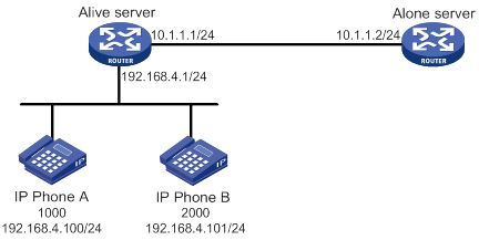
Configuration procedure
1. Configure the Alive server:
# Enable SIP-to-SIP calling.
<Alive> system-view
[Alive] voice-setup
[Alive-voice] allow-connections sip to sip
# Enable the SIP registrar.
[Alive-voice] sip
[Alive-voice-sip] registrar server
[Alive-voice-sip] quit
# Specify the survivable mode, and set the maximum numbers to 10 for both register pools and DNs.
[Alive] voice-setup
[Alive-voice] voice register global
[Alive-voice-register-global] mode alive
[Alive-voice-register-global] max-pool 10
[Alive-voice-register-global] max-dn 10
[Alive-voice-register-global] quit
# Create DN 1, configure the register number template as 1000, and set the priority for dynamic VoIP entities to 1.
[Alive-voice] voice register dn 1
[Alive-voice-register-dn1] number 1000$
[Alive-voice-register-dn1] priority 1
[Alive-voice-register-dn1] quit
# Create register pool 1, and permit IP phone A with IP address 192.168.4.100 to register.
[Alive-voice] voice register pool 1
[Alive-voice-register-pool1] id ip 192.168.4.100
# Apply the register number template of DN 1 to register pool 1, and set the priority for dynamic VoIP entities to 2.
[Alive-voice-register-pool1] number 1 dn 1
[Alive-voice-register-pool1] priority 2
# Specify the Alone server as the remote voice server and enable the keepalive feature.
[Alive-voice-register-pool1] proxy ip 10.1.1.2 monitor probe sip
[Alive-voice-register-pool1] quit
# Create register pool 2, and permit IP phone B with IP address 192.168.4.101 to register.
[Alive-voice] voice register pool 2
[Alive-voice-register-pool2] id ip 192.168.4.101
# Configure the register number template to 2000, and set the priorities of dynamic VoIP entities to 3.
[Alive-voice-register-pool2] number 1 2000$
[Alive-voice-register-pool2] priority 3
# Specify the remote voice server as the Alone server.
[Alive-voice-register-pool2] proxy ip 10.1.1.2
[Alive-voice-register-pool2] quit
# Display registration information in all register pools.
[Alive-voice] display voice register pool all brief
Pool ID IP Address Ln DN Number State
-----------------------------------------------------------------------------
1 192.168.4.100 1 1 1000 Unregistered
2 192.168.4.101 1 2000 Unregistered
The output shows that IP phone A and IP phone B do not register with the Alive server.
# Display information about all dynamic VoIP entities created in register pools.
[Alive-voice] display voice register entity all
Entities created dynamically on register pool 1:
There are no entities in this pool.
Entities created dynamically on register pool 2:
There are no entities in this pool.
2. Configure the Alone server:
# Enable SIP-to-SIP calling.
<Alone> system-view
[Alone] voice-setup
[Alone-voice] allow-connections sip to sip
# Enable the SIP registrar.
[Alone-voice] sip
[Alone-voice-sip] registrar server
[Alone-voice-sip] quit
# Specify the standalone mode, and set the maximum numbers to 10 for both register pools and DNs.
[Alone] voice-setup
[Alone-voice] voice register global
[Alone-voice-register-global] mode alone
[Alone-voice-register-global] max-pool 10
[Alone-voice-register-global] max-dn 10
[Alone-voice-register-global] quit
# Create DN 1, configure the register number template as 1000, and set the priority of dynamic VoIP entities to 1.
[Alone] voice-setup
[Alone-voice] voice register dn 1
[Alone-voice-register-dn1] number 1000$
[Alone-voice-register-dn1] priority 1
[Alone-voice-register-dn1] quit
# Create register pool 1, permit IP phone A with IP address 192.168.4.100 to register, and set the priority of dynamic VoIP entities to 2.
[Alone] voice-setup
[Alone-voice] voice register pool 1
[Alone-voice-register-pool1] id ip 192.168.4.100
[Alone-voice-register-pool1] number 1 dn 1
[Alone-voice-register-pool1] priority 2
[Alone-voice-register-pool1] quit
# Create register pool 2, permit IP phone B with IP address 192.168.4.101 to register, and set the priority of dynamic VoIP entities to 3.
[Alone-voice] voice register pool 2
[Alone-voice-register-pool2] id ip 192.168.4.101
[Alone-voice-register-pool2] number 1 2000$
[Alone-voice-register-pool2] priority 3
[Alone-voice-register-pool2] quit
# Display registration information in all register pools.
[Alone-voice] display voice register pool all brief
Pool ID IP Address Ln DN Number State
-----------------------------------------------------------------------------
1 192.168.4.100 1 1 1000 Unregistered
2 192.168.4.101 1 2000 Unregistered
The output shows that IP phone A and IP phone B do not register with the Alone server.
# Display information about dynamic VoIP entities created in register pools.
[Alone-voice] display voice register entity all
Entities created dynamically on register pool 1:
There are no entities in this pool.
Entities created dynamically on register pool 2:
There are no entities in this pool.
Verifying the configuration
1. Verify that IP phone A and IP phone B can register with the Alive server.
# Register IP phone A and IP phone B with the Alive server. (Details not shown.)
# Display registration information for all register pools on the Alive server.
[Alive] display voice register pool all brief
Pool ID IP Address Ln DN Number State
------------------------------------------------------------------------------
1 192.168.4.100 192.168.4.100 1 1 1000$ Registered
2 192.168.4.101 192.168.4.101 1 2000$ Registered
The output shows that IP phone A and IP phone B have successfully registered with the Alive server.
# Display information about dynamic VoIP entities on the Alive server.
[Alive] display voice register entity all
Entities created dynamically on register pool 1:
entity 40001 voip
match-template 1000$
address sip ip 192.168.4.100 port 10002
session transport udp
priority 1
entity 40002 voip
match-template 1000$
address sip ip 10.1.1.2 port 5060
session transport global
Entities created dynamically on register pool 2:
entity 40003 voip
match-template 2000$
address sip ip 192.168.4.101 port 10003
session transport udp
priority 3
entity 40004 voip
match-template 2000$
address sip ip 10.1.1.2 port 5060
session transport global
The output shows the following information:
? In register pool 1, dynamic VoIP entities 40001 and 40002 are created, with call destinations as IP phone A and the Alone server, respectively.
? In register pool 2, dynamic VoIP entities 40003 and 40004 are created, with call destinations as IP phone B and the Alone server, respectively.
2. Verify that IP phone A and IP phone B can register with the Alone server:
# Register IP phone A and IP phone B with the Alone server. (Details not shown.)
# Display registration information for all register pools on the Alone server.
[Alone] display voice register pool all brief
Pool ID IP Address Ln DN Number State
----------------------------------------------------------------------------------------
1 192.168.4.100 192.168.4.100 1 1 1000$ Registered
2 192.168.4.101 192.168.4.101 1 2000$ Registered
The output shows that IP phone A and IP phone B have successfully registered with the Alone server.
# Display information about dynamic VoIP entities on the Alone server.
[Alone] display voice register entity all
Entities created dynamically on register pool 1:
entity 40001 voip
match-template 1000$
address sip ip 192.168.4.100 port 10002
session transport udp
priority 1
Entities created dynamically on register pool 2:
entity 40002 voip
match-template 2000$
address sip ip 192.168.4.101 port 10003
session transport udp
priority 3
The output shows the following information:
? In register pool 1, dynamic VoIP entity 40001 is created, with call destination as the Alive server.
? In register pool 2, dynamic VoIP entity 40002 is created, with call destination as the Alive server.
Keepalive feature configuration example
Network requirements
As shown in Figure 67, the Alone server processes calls between IP phone A and IP phone B.
Configure the keepalive feature for the Alive server to take over when the Alone server is down.
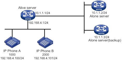
Configuration procedure
1. Configure the SIP registrar feature on the Alive server and the Alone server. For more information, see "SIP registrar configuration example."
2. Configure the keepalive feature:
# In register pool 1, specify the master and backup remote voice servers and enable the keepalive feature.
[Alive-voice-register-pool1] proxy ip 10.1.1.2 monitor probe sip 10.1.1.3
# Configure the parameters for the keepalive feature.
[Alive-voice-register-pool1] voice-class sip options-keepalive up-interval 100 down-interval 50 retry 3
# In register pool 2, specify the master and backup remote voice servers and enable the keepalive feature.
[Alive-voice-register-pool2] proxy ip 10.1.1.2 monitor probe sip 10.1.1.3
# Configure the parameters for the keepalive feature.
[Alive-voice-register-pool2] voice-class sip options-keepalive up-interval 100 down-interval 50 retry 3
Verifying the configuration
# Display information about dynamic VoIP entities in register pools on the Alive server.
[Alive] display voice register entity all
Entities created dynamically on register pool 1:
entity 40001 voip
match-template 1000$
address sip ip 192.168.4.100 port 10002
session transport udp
priority 1
entity 40002 voip
match-template 1000$
address sip ip 10.1.1.2 port 5060: VoIP entity available
session transport global
Entities created dynamically on register pool 2:
entity 40003 voip
match-template 2000$
address sip ip 192.168.4.101 port 10003
session transport udp
priority 3
entity 40004 voip
match-template 2000$
address sip ip 10.1.1.2 port 5060: VoIP entity available
session transport global
The output shows that the Alone server is available.
PSTN backup configuration example
Network requirements
As shown in Figure 68, the Alone server processes calls between all IP phones.
Configure POTS entities on the Alive servers, so IP phones can call each other over the PSTN network when the Alone server is down.
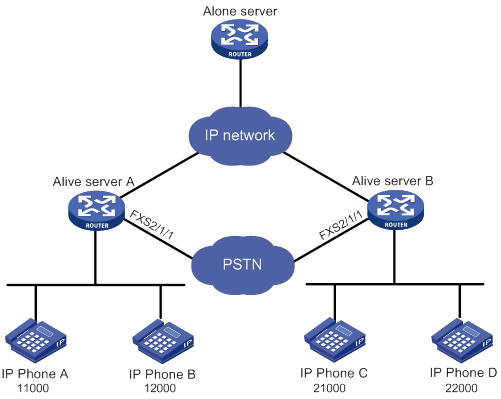
Configuration procedure
1. Configure the SIP registrar feature on the Alive servers and the Alone server. For more information, see "SIP registrar configuration example."
2. Configure POTS entities:
# On Alive server A, create POTS entity 2, and bind FXS interface line 2/1/1 to POTS entity 2.
[AliveA] voice-setup
[AliveA-voice] dial-program
[AliveA-voice-dial] entity 2 pots
[AliveA-voice-dial-entity2] line 2/1/1
# Configure the number template as 2…. for POTS entity 2, and set the priority of the POTS entity to 5.
[AliveA-voice-dial-entity2] match-template 2....
[AliveA-voice-dial-entity2] priority 5
# On Alive server B, create POTS entity 1, and bind FXS interface line 2/1/1 to POTS entity 1.
[AliveB] voice-setup
[AliveB-voice] dial-program
[AliverB-voice-dial] entity 1 pots
[AliveB-voice-dial-entity1] line 2/1/1
# Configure the number template as 1…. for POTS entity 1, and set the priority of the POTS entity to 5.
[AliveB-voice-dial-entity1] match-template 1....
[AliveB-voice-dial-entity1] priority 5
Verifying the configuration
# Verify that IP phone A and IP phone C can call each other when the Alone server is down. (Details not shown.)
Basic call services configuration example
Network requirements
As shown in Figure 69, the Alone server processes calls between all IP phones.
Configure the Alive servers and the Alone server to meet the following requirements:
· IP phones within a branch can call each other.
· IP phones in different branches can call each other.
· All IP phones can call each other when the Alone server is down.
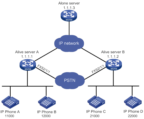
Configuration procedure
1. Configure the SIP registrar feature on the Alive servers and the Alone server. For more information, see "SIP registrar configuration example."
2. Configure the Alone server:
[Alone] voice-setup
[Alone-voice] dial-program
[Alone-voice-dial] entity 10 voip
[Alone-voice-dial-entity10] address sip ip 1.1.1.1
[Alone-voice-dial-entity10] match-template 1.T
[Alone-voice-dial-entity10] quit
# Create VoIP entity 11, configure the call destination IP address as 1.1.1.2, and configure the number template as 2.T.
[Alone-voice-dial] entity 11 voip
[Alone-voice-dial-entity11] address sip ip 1.1.1.2
[Alone-voice-dial-entity11] match-template 2.T
[AliveA] voice-setup
[AliveA-voice] dial-program
[AliveA-voice-dial] entity 10 voip
[AliveA-voice-dial-entity10] address sip ip 1.1.1.3
[AliveA-voice-dial-entity10] match-template .T
# Enable the keepalive function for VoIP entity 11.
[AliveA-voice-dial-entity10] voice-class sip options-keepalive
[AliveA-voice-dial-entity10] quit
[AliveB] voice-setup
[AliveB-voice] dial-program
[AliveB-voice-dial] entity 11 voip
[AliveB-voice-dial-entity11] address sip ip 1.1.1.3
[AliveB-voice-dial-entity11] match-template .T
# Enable the keepalive function for VoIP entity 11.
[AliveB-voice-dial-entity11] voice-class sip options-keepalive
For more information, see "PSTN backup configuration example."
Verifying the configuration
# Verify that IP phone A and IP phone B can call each other and that IP phone C and D can call each other. (Details not shown.)
# Verify that IP phone A and IP phone C can call each other and that IP phone B and D can call each other. (Details not shown.)
# Verify that IP phone A and IP phone C can call each other when the Alone server is down. (Details not shown.)
MOH configuration example
Network requirements
As shown in Figure 70, the call management server in the headquarters processes calls between IP phones in the two branches.
Configure MOH on Alive server A and Alive server B.
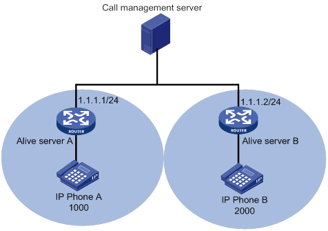
Configuration procedure
1. Configure the SIP registrar feature on Alive server A and Alive server B. For more information, see "SIP registrar configuration example."
2. Save the media files g711u1.wav and g711u2.wav to the storage media on Alive server A and Alive server B, respectively. (Details not shown.)
[AliveA] voice-setup
[AliveA-voice] allow-connections sip to sip
[AliveA-voice] voice register global
[AliveA-voice-register-global] moh file g711u1.wav
[AliveA-voice-register-global] multicast moh ip 239.1.1.1 port 2008 route 1.1.1.1
[AliveB] voice-setup
[AliveB-voice] allow-connections sip to sip
[AliveB-voice] voice register global
[AliveB-voice-register-global] moh file g711u2.wav
[AliveB-voice-register-global] multicast moh ip 239.1.1.2 port 2009 route 1.1.1.2
Verifying the configuration
# Verify that IP phone B held by IP phone A can hear the music of g711u2.wav. (Details not shown.)
# Verify that IP phone A held by IP phone B can hear the music of g711u1.wav. (Details not shown.)
MWI configuration example
Network requirement
As shown in Figure 71, the SIP server processes calls between IP phone A and IP phone B. IP phone A and IP phone B subscribe to the MWI service.
Configure MWI on the Alive server so that IP phone A and IP phone B can receive MWI messages when the SIP server is down.
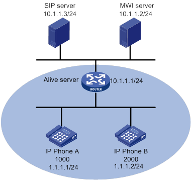
Configuration procedure
1. Configure the SIP registrar feature on the Alive server. For more information, see "SIP registrar configuration example."
2. Configure MWI on the Alive server:
# Specify a voice mail server with the IP address 10.1.1.2.
[Server] voice-setup
[Server-voice] sip
[Server-voice-sip] mwi-server ip 10.1.1.2
[Server-voice-sip] quit
# Enable MWI for DN 1 and DN 2.
[Server-voice] voice register dn 1
[Server-voice-register-dn1] mwi
[Server-voice-register-dn1] quit
[Server-voice] voice register dn 2
[Server-voice-register-dn2] mwi
[Server-voice-register-dn2] return
Verifying the configuration
# Display the subscription states for phone numbers on the Alive server.
<Server> display voice sip subscribe-state
Number Server Address Expires Status
--------------------------------------------------------------------------
1000 10.1.1.1:5060 2285 Online
2000 10.1.1.1:5060 2326 Online
The output shows that IP phone A and IP phone B have successfully subscribed to the MWI service.
# Display MWI information for phone numbers that have a subscription on the Alive server.
<Server> display voice mwi all
Message Waiting Indication Information:
---------------------------------------------------------------------
MWI type: Solicited
MWI server: 10.1.1.2 port: 5060
MWI expires: 3600
---------------------------------------------------------------------
Number: 1000
Messages-Waiting: Yes
Voicemail: 3/0 (0/0)
Total: 3(0)
---------------------------------------------------------------------
Number: 2000
Messages-Waiting: No
Total: 0(0)
Call pickup configuration example
Network requirements
As shown in Figure 72, the Alone server processes calls between the IP phones.
Configure call pickup on the Alone server so that IP phone C can answer calls for IP phone A.
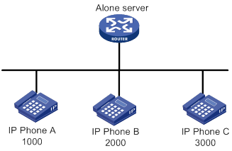
Configuration procedure
1. Configure the SIP registrar feature on the Alone server. For more information, see "SIP registrar configuration example."
? (Method 1) Configure direct call pickup.
? (Method 2) Configure local group pickup:
[Server] voice-setup
[Server-voice] voice register dn 1
[Server-voice-register-dn1] pickup-group 1
[Server-voice-register-dn1] number 1000$
[Server-voice-register-dn1] quit
# Create DN 3, assign DN 3 to pickup group 1, and configure the register number template as 3000$ for the DN.
[Server-voice] voice register dn 3
[Server-voice-register-dn3] pickup-group 1
[Server-voice-register-dn3] number 3000$
? (Method 3) Configure group pickup.
# Create DN 1, and configure the register number template as 1 for the DN.
[Server] voice-setup
[Server-voice] voice register dn 1
[Server-voice-register-dn1] number 1000$
# Assign DN 1 to pickup group 1.
[Server-voice-register-dn1] pickup-group 1
Verifying the configuration
· Verify that IP phone C can directly pick up calls for IP phone A.
# Place a call from IP phone B to IP phone A. (Details not shown.)
# When IP phone A rings, press the GPickUp softkey and dial 1000 on IP phone C. The call is established between IP phone C and IP phone A. (Details not shown.)
· Verify that IP phone C can pick up calls for IP phone A in the same pickup group.
# Place a call from IP phone B to IP phone A. (Details not shown.)
# When IP phone A rings, press the PickUp softkey or the GPickUp softkey plus the asterisk (*) key on IP phone C. The call is established between IP phone C and IP phone A. (Details not shown.)
· Verify that IP phone C can pick up calls for IP phone A in a different pickup group.
# Place a call from IP phone B to IP phone A. (Details not shown.)
# When IP phone A rings, press the GPickUp softkey and dial 1 on IP phone C. The call is established between IP phone C and IP phone A. (Details not shown.)
DND configuration example
Network requirements
As shown in Figure 73, Router A is a SIP gateway. the Alone server processes calls between Telephone A and IP phone B.
Configure DND for Telephone A on the Alone server.
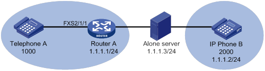
Configuration procedure
1. Configure the Alone server:
[Server] voice-setup
[Server-voice] allow-connections sip to sip
# Specify the standalone mode.
[Server-voice] voice register global
[Server-voice-register-global] mode alone
[Server-voice-register-global] quit
[Server-voice-sip] registrar server
[Server-voice-sip] quit
[Server-voice] voice register pool 1
[Server-voice-register-pool1] number 1 1000$
[Server-voice-register-pool1] id ip 1.1.1.1
[Server-voice-register-pool1] dnd
[Server-voice-register-pool1] quit
# Create register pool 2, and permit IP phone B with number 2000 and IP address 1.1.1.2 to register.
[Server-voice] voice register pool 2
[Server-voice-register-pool2] number 1 2000$
[Server-voice-register-pool2] id ip 1.1.1.2
[Server-voice-register-pool2] quit
# Specify a registrar with IP address 1.1.1.3.
[RouterA] voice-setup
[RouterA-voice] sip
[RouterA-voice-sip] registrar 1 ip 1.1.1.3
[RouterA-voice-sip] quit
[RouterA-voice-dial] entity 1 pots
[RouterA-voice-dial-entity1] line 2/1/1
[RouterA-voice-dial-entity1] match-template 1000$
Verifying the configuration
# Verify that you hear ring back tones when you place a call from Telephone A to IP phone B. (Details not shown.)
Call forwarding configuration example
Network requirements
As shown in Figure 74, Router A and Router C are voice gateways. The Alone server processes calls between all IP phones and telephones.
Configure call forwarding on the devices to meet the following requirements:
· Incoming calls for IP phone B will be unconditionally forwarded to Telephone C.
· Incoming calls for Telephone D will be forwarded to IP phone E if Telephone D fails to register with the Alone server.
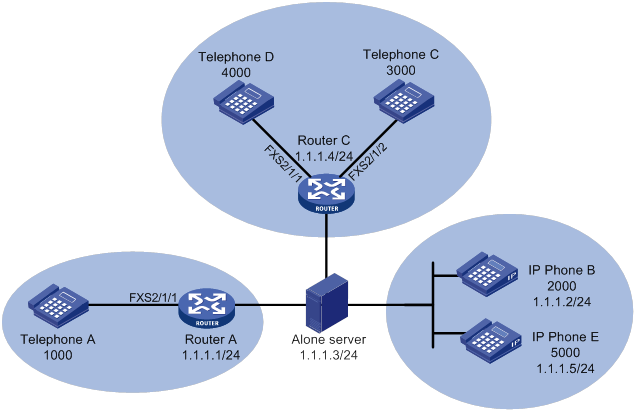
Configuration procedure
1. Configure the Alone server:
[Server] voice-setup
[Server-voice] allow-connections sip to sip
# Specify the standalone mode.
[Server-voice] voice register global
[Server-voice-register-global] mode alone
[Server-voice-register-global] quit
[Server-voice-sip] registrar server
[Server-voice-sip] quit
[Server-voice] voice register pool 1
[Server-voice-register-pool1] number 1 1000$
[Server-voice-register-pool1] id ip 1.1.1.1
[Server-voice-register-pool1] quit
# Create register pool 2, and permit Telephone B with number 2000 and IP address 1.1.1.2 to register.
[Server-voice] voice register pool 2
[Server-voice-register-pool2] number 1 2000$
[Server-voice-register-pool2] id ip 1.1.1.2
# Enable call forwarding unconditional and set the forward-to number to 3000.
[Server-voice-register-pool2] call-forward b2bua all 3000
[Server-voice-register-pool2] quit
[Server-voice] voice register pool 3
[Server-voice-register-pool3] number 1 3000$
[Server-voice-register-pool3] id ip 1.1.1.4
[Server-voice-register-pool3] quit
[Server-voice] voice register pool 4
[Server-voice-register-pool4] number 1 5000$
[Server-voice-register-pool4] id ip 1.1.1.5
[Server-voice-register-pool4] quit
[Server-voice] voice register dn 1
[Server-voice-register-dn1] number 4000$
[Server-voice-register-dn1] call-forward b2bua unregistered 5000
# Specify a registrar with IP address 1.1.1.3.
[RouterA] voice-setup
[RouterA-voice] sip
[RouterA-voice-sip] registrar 1 ip 1.1.1.3
[RouterA-voice-sip] quit
[RouterA-voice-dial] entity 1 pots
[RouterA-voice-dial-entity1] line 2/1/1
[RouterA-voice-dial-entity1] match-template 1000$
# Specify a registrar with IP address 1.1.1.3.
[RouterC] voice-setup
[RouterC-voice] sip
[RouterC-voice-sip] registrar 1 ip 1.1.1.3
[RouterC-voice-sip] quit
[RouterC-voice-dial] entity 1 pots
[RouterC-voice-dial-entity1] line 2/1/2
[RouterC-voice-dial-entity1] match-template 3000$
[RouterC-voice-dial-entity1] quit
# Create POTS entity 2, and bind FXS interface line 2/1/1 to the entity.
[RouterC-voice-dial] entity 2 pots
[RouterC-voice-dial-entity2] line 2/1/1
# Configure the number template as 4000 for POTS entity 2, and configure POTS entity 2 to deregister the phone number 4000 from the registrar.
[RouterC-voice-dial-entity2] match-template 4000$
[RouterC-voice-dial-entity2] undo register-number
Verifying the configuration
# Verify that Telephone C rings when you place a call from Telephone A to IP phone B. (Details not shown.)
# Verify that Telephone E rings when you place a call from Telephone A to Telephone D. (Details not shown.)
Call blocking configuration example
Network requirements
As shown in Figure 75, the Alone server processes calls between IP phones.
Configure call blocking on the Alone server so calls for IP phone B will be blocked on Sunday.
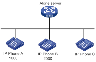
Configuration procedure
1. Configure the SIP registrar feature on the Alone server. For more information, see "SIP registrar configuration example."
# Enable call blocking for numbers 1000 and 2000, 24 hours on Sunday.
[Server] voice-setup
[Server-voice] after-hours block pattern 1 1000$
[Server-voice] after-hours block pattern 2 2000$
[Server-voice] after-hours day Sun 00:00 23:59
# Create DN 1, and exempt number 1000 from call blocking.
[Server-voice] voice register dn 1
[Server-voice-register-dn1] after-hours exempt
[Server-voice-register-dn1] number 1000$
Verifying the configuration
# Verify that you hear busy tones when you place a call from IP phone C to IP phone B on Sunday. (Details not shown.)
# Verify that you hear ring back tones when you place a call from IP phone C to IP phone A on Sunday. (Details not shown.)
FACs configuration example (on a gateway)
Network requirements
As shown in Figure 76, Router A is a voice gateway. Configure FACs on Router A so that incoming calls for Telephone A are forwarded to Telephone B.
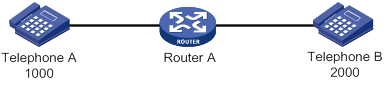
Configuration procedure
· (Method 1) Configure standard FACs.
<RouterA> system-view
[RouterA] voice-setup
[RouterA-voice] fac standard
· (Method 2) Configure custom FACs.
<RouterA> system-view
[RouterA] voice-setup
[RouterA-voice] fac custom callfwd busy 123
[RouterA-voice] fac custom callfwd busy-cancel 456
[RouterA-voice] fac terminator 7
Verifying the configuration
· Verify that standard FACs for the call forwarding service are correctly configured.
# Dial *57*, and then dial 2000 on Telephone A. You will hear three beeps, which means the call forwarding service is successfully activated. (Details not shown.)
# Dial #57# on Telephone A. You will hear three beeps, which means the call forwarding service is successfully deactivated. (Details not shown.)
· Verify that custom FACs for the call forwarding service are correctly configured.
# Dial 12320007 on Telephone A. You will hear three beeps, which means the call forwarding service is successfully activated. (Details not shown.)
# Dial 456 on Telephone A to deactivate the call forwarding busy service. (Details not shown.)
FACs for the call forwarding service configuration example (on a voice server)
Network requirements
As shown in Figure 77, Router A and Router B are voice gateways. Telephone A, IP phone B, and Telephone C have registered with the Alone server. The Alone server processes calls between the phones.
Configure standard FACs on the Alone server to activate the call forwarding service on Telephone A.
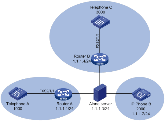
Configuration procedure
1. Configure the Alone server:
# Specify the standalone mode.
<Server> system-view
[Server] voice-setup
[Server-voice] allow-connections sip to sip
[Server-voice] voice register global
[Server-voice-register-global] mode alone
[Server-voice-register-global] quit
# Enable the SIP registrar.
[Server-voice] sip
[Server-voice-sip] registrar server
[Server-voice-sip] quit
# Enable standard FACs.
[Server-voice] fac standard
# Create register pool 1, and permit Telephone A with number 1000 and IP address 1.1.1.1 to register.
[Server-voice] voice register pool 1
[Server-voice-register-pool1] number 1 1000$
[Server-voice-register-pool1] id ip 1.1.1.1
[Server-voice-register-pool1] quit
# Create register pool 2, and permit Telephone B with number 2000 and IP address 1.1.1.2 to register.
[Server-voice] voice register pool 2
[Server-voice-register-pool2] number 1 2000$
[Server-voice-register-pool2] id ip 1.1.1.2
[Server-voice-register-pool2] quit
# Create register pool 3, and permit Telephone C with number 3000 and IP address 1.1.1.4 to register.
[Server-voice] voice register pool 3
[Server-voice-register-pool3] number 1 3000$
[Server-voice-register-pool3] id ip 1.1.1.4
[Server-voice-register-pool3] quit
2. Configure Router A:
# Specify a registrar with IP address 1.1.1.3.
<RouterA> system-view
[RouterA] voice-setup
[RouterA-voice] sip
[RouterA-voice-sip] registrar 1 ip 1.1.1.3
[RouterA-voice-sip] quit
# Create POTS entity 1, bind FXS interface line 2/1/1 to the entity, and configure the number template as 1000 for the entity.
[RouterA-voice] dial-program
[RouterA-voice-dial] entity 1 pots
[RouterA-voice-dial-entity1] line 2/1/1
[RouterA-voice-dial-entity1] match-template 1000
[RouterA-voice-dial-entity1] quit
# Create VoIP entity 2, configure the number template as *40*1234, and call destination as 1.1.1.3 for the entity.
[RouterA-voice-dial] entity 2 voip
[RouterA-voice-dial-entity2] match-template *40*1234
[RouterA-voice-dial-entity2] address sip ip 1.1.1.3
Verifying the configuration
# Dial *40*1234 on Telephone A. You will hear three beeps, which means the call forwarding service is activated. (Details not shown.)
FACs for the call pickup service configuration example (on a voice server)
Network requirements
As shown in Figure 78, Router A and Router B are voice gateways. Telephone A, IP phone B, and Telephone C have registered with the Alone server. The Alone server processes calls between the phones.
Configure standard FACs on the Alone server to activate direct call pickup on Telephone C.
Configuration procedure
1. Configure the Alone server:
# Specify the standalone mode.
<Server> system-view
[Server] voice-setup
[Server-voice] allow-connections sip to sip
[Server-voice] voice register global
[Server-voice-register-global] mode alone
[Server-voice-register-global] quit
# Enable the SIP registrar.
[Server-voice] sip
[Server-voice-sip] registrar server
[Server-voice-sip] quit
# Enable standard FACs.
[Server-voice] fac standard
# Create register pool 1, and permit Telephone A with number 1000 and IP address 1.1.1.1 to register.
[Server-voice] voice register pool 1
[Server-voice-register-pool1] number 1 1000$
[Server-voice-register-pool1] id ip 1.1.1.1
[Server-voice-register-pool1] quit
# Create register pool 2, and permit Telephone B with number 2000 and IP address 1.1.1.2 to register.
[Server-voice] voice register pool 2
[Server-voice-register-pool2] number 1 2000$
[Server-voice-register-pool2] id ip 1.1.1.2
[Server-voice-register-pool2] quit
# Create register pool 3, and permit Telephone C with number 3000 and IP address 1.1.1.4 to register.
[Server-voice] voice register pool 3
[Server-voice-register-pool3] number 1 3000$
[Server-voice-register-pool3] id ip 1.1.1.4
[Server-voice-register-pool3] quit
2. Configure Router A:
# Specify a registrar with IP address 1.1.1.3.
<RouterA> system-view
[RouterA] voice-setup
[RouterA-voice] sip
[RouterA-voice-sip] registrar 1 ip 1.1.1.3
[RouterA-voice-sip] quit
# Create POTS entity 1, bind FXS interface line 2/1/1 to the entity, and configure the number template as 1000 for the entity.
[RouterA-voice] dial-program
[RouterA-voice-dial] entity 1 pots
[RouterA-voice-dial-entity1] line 2/1/1
[RouterA-voice-dial-entity1] match-template 1000
[RouterA-voice-dial-entity1] quit
# Create VoIP entity 2, configure the number template as 3000, and call destination as 1.1.1.3 for the entity.
[RouterA-voice-dial] entity 2 voip
[RouterA-voice-dial-entity2] match-template *40*1234
[RouterA-voice-dial-entity2] address sip ip 1.1.1.3
3. Configure Router B:
# Specify a registrar with IP address 1.1.1.3.
<RouterB> system-view
[RouterB] voice-setup
[RouterB-voice] sip
[RouterB-voice-sip] registrar 1 ip 1.1.1.3
[RouterB-voice-sip] quit
# Create POTS entity 1, bind FXS interface line 2/1/1 to the entity, and configure the number template as 3000 for the entity.
[RouterB-voice] dial-program
[RouterB-voice-dial] entity 1 pots
[RouterB-voice-dial-entity1] line 2/1/1
[RouterB-voice-dial-entity1] match-template 3000
[RouterB-voice-dial-entity1] quit
Verifying the configuration
# Verify that you can answer the call for Telephone C on Telephone B by dialing *80*3000. (Details not shown.)
Configuring customizable IVR
Overview
Interactive voice response (IVR) is extensively used in voice communications. The IVR system enables you to customize interactive operations and humanize other services. If a subscriber dials an IVR access number, the IVR system plays the prerecorded voice prompts to direct the subscriber about how to proceed.
Advantages
A conventional interactive voice system uses fixed media files and operations. IVR enables you to customize your own interactive system by adding, modifying, and removing media files. IVR has the following advantages:
· Customizable voice prompts—You can customize voice prompts, save them as a .wav file, and upload the file to a voice device. The voice device plays the customizable voice prompts to subscribers. The adding, modifying, and removing operations in the IVR system are simple and easy to use, and the configurations take effect immediately.
· Various codecs—The IVR system supports the following codecs for voice prompts:
? G.711alaw and G.711ulaw—Provide high voice quality but require large memory space.
? G.723r53 and G.729r8—Provide relatively low voice quality but require small memory space.
· Flexible node configuration—To simplify configuration, the IVR system uses nodes as basic units for configuration. You can define the following types of nodes:
? Call node—Executes a secondary call.
? Jump node—Jumps to another node according to user input. A maximum of eight successive jump operations are supported.
? Service node—Executes various operations, such as executing an immediate secondary call, jumping to another node, terminating a call, and playing a media file.
You can combine different node types to implement complex functions.
· Customizable process—The IVR system simplifies tasks such as configuring IVR access numbers, voice prompts, and combinations of keys and voice prompts.
· Error and timeout handling policies—The IVR system allows you to customize input error and timeout handling policies for call nodes and jump nodes. You can configure input error and timeout handling policies for a specific node or globally.
· Various types of secondary calls—The IVR system supports the following types of secondary calls:
? Immediate secondary call—A subscriber makes an immediate secondary call without dialing the number of the called party. Immediate secondary calls are executed by service nodes.
? Normal secondary call—A subscriber makes a normal secondary call by dialing the number of the called party. Normal secondary calls are executed by call nodes. You can configure a node to match the length of a number, match the terminator, or match the number.
? Extension secondary call—A subscriber makes an extension secondary call by dialing the extension number of the called party. Extension secondary calls are executed by call nodes.
Feature and hardware compatibility
|
Hardware |
Customizable IVR compatibility |
|
MSR810/810-W/810-W-DB/810-LM/810-W-LM/810-10-PoE/810-LM-HK/810-W-LM-HK/810-LMS/810-LUS |
No |
|
MSR2600-6-X1/2600-10-X1 |
Yes |
|
MSR 2630 |
Yes |
|
MSR3600-28/3600-51 |
Yes |
|
MSR3600-28-SI/3600-51-SI |
No |
|
MSR3610-X1/3610-X1-DP/3610-X1-DC/3610-X1-DP-DC |
Yes |
|
MSR 3610/3620/3620-DP/3640/3660 |
Yes |
|
MSR5620/5660/5680 |
Yes (not supported on the router installed with an SPU600-X1 card.) |
|
Hardware |
Customizable IVR compatibility |
|
MSR810-LM-GL |
No |
|
MSR810-W-LM-GL |
No |
|
MSR830-6EI-GL |
No |
|
MSR830-10EI-GL |
No |
|
MSR830-6HI-GL |
No |
|
MSR830-10HI-GL |
No |
|
MSR2600-6-X1-GL |
Yes |
|
MSR3600-28-SI-GL |
No |
Customizable IVR configuration task list
|
Remarks |
|
|
(Required.) Configuring an IVR entity |
N/A |
|
(Required.) Specifying an ID for a media file |
N/A |
|
(Optional.) Configuring global handling policies |
N/A |
|
(Required.) Configuring an IVR node |
Configure one or more node types according to your requirements. |
Configuring an IVR entity
When you use a VoIP entity to call an IVR access number, you must configure out-of-band DTMF to transmit the DTMF tones. For information about configuring out-of-band DTMF, see "Configuring SIP."
|
Step |
Command |
Remarks |
|
1. Enter system view. |
system-view |
N/A |
|
2. Enter voice view. |
voice-setup |
N/A |
|
3. Enter dial program view. |
dial-program |
N/A |
|
4. Create an IVR entity and enter its view. |
entity entity-number ivr |
By default, no IVR entities exist. |
|
5. Configure the root node (the first node of the IVR entity). |
ivr-root node-id |
By default, no root node is configured for an IVR entity. |
For information about configuring other functions for an IVR entity, see "Configuring voice entities."
Specifying an ID for a media file
You can enter the corresponding media resource management view by specifying a codec. In each media resource management view, you can specify an ID for a media file.
To specify an ID for a media file:
|
Step |
Command |
Remarks |
|
1. Enter system view. |
system-view |
N/A |
|
2. Enter voice view. |
voice-setup |
N/A |
|
3. Enter media resource management view. |
media-file { g711alaw | g711ulaw | g723r53 | g729r8 } |
N/A |
|
4. Specify an ID for a media file. |
set-media media-id file filename |
By default, no ID is specified for a media file. |
Configuring global handling policies
If you do not configure policies for handling input errors and timeouts for a node, it uses the global handling policies. If you configure policies both for a specific node and globally, the node uses its own policies.
To configure global handling policies:
|
Step |
Command |
Remarks |
|
1. Enter system view. |
system-view |
N/A |
|
2. Enter voice view. |
voice-setup |
N/A |
|
3. Enter IVR management view. |
ivr-system |
N/A |
|
4. Configure a global policy for handling input errors. |
global-input-error { media-play media-id [ play-times ] | repeat repeat-times } * |
By default, the system does not play voice prompts for input errors and terminates the call after three times of input errors. |
|
5. Configure a global policy for handling input timeouts. |
global-timeout { expires seconds | media-play media-id [ play-times ] | repeat repeat-times } * |
By default, the timeout time is 10 seconds. The system does not play voice prompts for input timeouts and terminates the call after three times of input timeouts. |
Configuring an IVR node
You can configure the following types of IVR nodes:
· Call node.
· Jump node.
· Service node.
Avoid the following misconfigurations:
· No operation is configured for a node.
· Several nodes form a loop. The subscriber has no other options except jumping around these nodes.
· The IVR process jumps from node to node for more than eight times.
For more information, see "Troubleshooting IVR."
To configure an IVR node:
|
Step |
Command |
Remarks |
|
1. Enter system view. |
system-view |
N/A |
|
2. Enter voice view. |
voice-setup |
N/A |
|
3. Enter IVR management view. |
ivr-system |
N/A |
|
4. Create an IVR node and its view. |
node node-id [ call | jump | service ] |
By default, no IVR nodes exist. |
|
5. Configure a description for the node. |
description string |
By default, no description exists. |
Configuring a call node
Call nodes support normal secondary calls and extension secondary calls. If you configure both types of secondary calls for a call node, the system places the call for the type that first matches the dialed number. If the dialed number matches both types of the secondary calls, the system places the extension secondary call.
Because a call node requires user input, configure input error and timeout handling policies for a call node. If you do not configure handling policies for a call node, the node uses global handling policies.
A timeout under a call node is different from that under a jump node. A timeout under a call node can be either a timeout before the first dial or after the first dial. If the timeout happens before the first dial, the system applies the input timeout handling policy. If the timeout happens after the first dial, the system applies the input error handling policy.
To configure a call node:
|
Step |
Command |
Remarks |
|
1. Enter system view. |
system-view |
N/A |
|
2. Enter voice view. |
voice-setup |
N/A |
|
3. Enter IVR management view. |
ivr-system |
N/A |
|
4. Enter call node view. |
node node-id call |
N/A |
|
5. Configure a dial program for the call node. |
·
Method 1: ·
Method 2: |
Use either method. |
|
6. (Optional.) Configure a dial prefix for the call node. |
dial-prefix string |
By default, no dial prefix is configured for a call node. |
|
7. (Optional.) Specify the media file that is played when the call node is waiting for user input. |
media-play media-id [ play-times ] [ force ] |
By default, no media file is played when a call node is waiting for user input. |
|
8. Configure an input error handling policy for the call node. |
input-error { end-call | goto-pre-node | goto-node node-id } [ media-play media-id [ play-times ] | repeat repeat-times ] * |
By default, the global input error handling policy is used for a call node. |
|
9. Configure an input timeout handling policy for the call node. |
timeout { end-call | goto-pre-node | goto-node node-id } [ expires seconds | media-play media-id [ play-times ] | repeat repeat-times ] * |
By default, the global input timeout handling policy is used for a call node. |
Configuring a jump node
You can configure the following functions for a jump node:
· Playing a media file.
· Jumping to another node.
· Terminating a call.
Because a jump node requires user input, configure input error and timeout handling policies for a jump node. If you do not configure handling policies for a jump node, the node uses global handling policies.
To configure a jump node:
|
Step |
Command |
Remarks |
|
1. Enter system view. |
system-view |
N/A |
|
2. Enter voice view. |
voice-setup |
N/A |
|
3. Enter IVR management view. |
ivr-system |
N/A |
|
4. Enter jump node view. |
node node-id jump |
N/A |
|
5. Configure a jump operation for a character. |
user-input character { end-call | goto-node node-id | goto-pre-node } |
By default, no jump operation is configured for a character. |
|
6. (Optional.) Specify the media file that is played when the call node is waiting for user input. |
media-play media-id [ play-times ] [ force ] |
By default, no media file is played when a call node is waiting for user input. |
|
7. Configure an input error handling policy for the jump node. |
input-error { end-call | goto-pre-node | goto-node node-id } [ media-play media-id [ play-times ] | repeat repeat-times ] * |
By default, the global input error handling policy is used for a jump node. |
|
8. Configure an input timeout handling policy for the jump node. |
timeout { end-call | goto-pre-node | goto-node node-id } [ expires seconds | media-play media-id [ play-times ] | repeat repeat-times ] * |
By default, the global input timeout handling policy is used for a jump node. |
Configuring a service node
You can configure the following functions for a service node:
· Executing an immediate secondary call.
· Jumping to another node.
· Terminating a call.
· Playing a media file.
You can configure a maximum of three functions for a service node and specify the execution order of the functions. If you do not specify the execution order, the default execution order is 1 > 2 > 3.
If an executed function is to jump to another node or to terminate a call, the remaining functions are not executed. For more information, see "Service node configuration example 2."
Because a service node does not involve user input, you do not need to configure input error and timeout handling policies for a service node.
To configure a service node:
|
Step |
Command |
Remarks |
|
1. Enter system view. |
system-view |
N/A |
|
2. Enter voice view. |
voice-setup |
N/A |
|
3. Enter IVR management view. |
ivr-system |
N/A |
|
4. Enter service node view. |
node node-id service |
N/A |
|
5. Specify the execution order of configured functions. |
select-rule 1st-operation 2nd-operation 3rd-operation |
The default execution order is 1 >2 > 3. |
|
6. Configure an operation for the service node. |
operation number { call-immediate call-number | end-call | goto-node node-id | goto-pre-node | media-play media-id [ play-times ] } |
By default, no operations are enabled for a service node. Repeat this command to configure more functions for the service node. |
Displaying and maintaining customizable IVR
Execute display commands in any view.
|
Task |
Command |
|
Display playing information. |
display voice media-play |
|
Display IVR call information. |
display voice ivr call-info |
|
Display media file information. |
display voice media-source |
Customizable IVR configuration examples
This section provides customizable IVR configuration examples.
Call node configuration example 1: dial terminator match, normal secondary call
Network requirements
As shown in Figure 79, configure an IVR access number and customize call node functions on Router B to achieve the following purposes:
· After a subscriber originates a SIP call by dialing 300 (the IVR access number of Router B) at Telephone A, Router B plays the media file welcome.wav. Then, after the subscriber dials 50# at Telephone A to originate a secondary call, Telephone B1 rings.
· In the case of an input error, Router B plays the media file input_error.wav.
· In the case of an input timeout, Router B plays the media file timeout.wav.
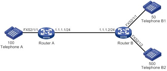
Configuration procedure
# Configure the local number as 100 for POTS entity 100, and bind FXS interface line 2/1/1 to the POTS entity.
<RouterA> system-view
[RouterA] voice-setup
[RouterA-voice] dial-program
[RouterA-voice-dial] entity 100 pots
[RouterA-voice-dial-entity100] match-template 100
[RouterA-voice-dial-entity100] line 2/1/1
[RouterA-voice-dial-entity100] quit
# Configure the called number as 300 for VoIP entity 300, and configure the destination IP address as 1.1.1.2.
[RouterA-voice-dial] entity 300 voip
[RouterA-voice-dial-entity300] match-template 300
[RouterA-voice-dial-entity300] address sip ip 1.1.1.2
[RouterA-voice-dial-entity300] outband sip
# Configure the local number as 500 for POTS entity 500, and bind FXS interface line 2/1/2 to the POTS entity.
<RouterB> system-view
[RouterB] voice-setup
[RouterB-voice] dial-program
[RouterB-voice-dial] entity 500 pots
[RouterB-voice-dial-entity500] match-template 500
[RouterB-voice-dial-entity500] line 2/1/2
[RouterB-voice-dial-entity500] quit
# Configure the local number as 50 for POTS entity 50, and bind FXS interface line 2/1/1 to the POTS entity.
[RouterB-voice-dial] entity 50 pots
[RouterB-voice-dial-entity50] match-template 50
[RouterB-voice-dial-entity50] line 2/1/1
[RouterB-voice-dial-entity50] quit
# Configure an access number of 300 for IVR entity 300, and specify node 10 as the root node.
[RouterB-voice-dial] entity 300 ivr
[RouterB-voice-dial-entity300] match-template 300
[RouterB-voice-dial-entity300] ivr-root 10
[RouterB-voice-dial-entity300] quit
[RouterB-voice-dial] quit
# Specify IDs for media files as follows:
? Specify ID 10001 for the media file cfa0:/wav/g729r8/welcome.wav.
? Specify ID 10002 for the media file cfa0:/wav/g729r8/timeout.wav.
? Specify ID 10003 for the media file cfa0:/wav/g729r8/input_error.wav.
[RouterB-voice] media-file g729r8
[RouterB-voice-media-g729r8] set-media 10001 file cfa0:/wav/g729r8/welcome.wav
[RouterB-voice-media-g729r8] set-media 10002 file cfa0:/wav/g729r8/timeout.wav
[RouterB-voice-media-g729r8] set-media 10003 file cfa0:/wav/g729r8/input_error.wav
[RouterB-voice-media-g729r8] quit
# Configure global policies for handling input errors and timeouts.
[RouterB-voice-ivr] global-input-error repeat 3 media-play 10003
[RouterB-voice-ivr] global-timeout repeat 4 expires 5 media-play 10002
# Configure call node 10 as follows:
? After the IVR access number 300 is matched, Router B plays the media file welcome.wav
? After the subscriber dials 50# at Telephone A, Router B originates a secondary call to Telephone B1.
[RouterB-voice-ivr] node 10 call
[RouterB-voice-ivr-node10] media-play 10001
[RouterB-voice-ivr-node10] call-normal terminator #
Verifying the configuration
# Dial the number 300 at Telephone A to verify that the media file welcome.wav is played.
# After the media file welcome.wav is played, dial 50# at Telephone A to verify that Telephone B1 rings.
Call node configuration example 2: number length match, normal secondary call
Network requirements
As shown in Figure 80, configure an IVR access number and customize call node functions on Router B to achieve the following purposes:
· After a subscriber originates a call by dialing 300 (the IVR access number of Router B) at Telephone A, Router B plays the media file welcome.wav. Then, after the subscriber dials a 3-digit number 500, Telephone B2 rings.
· In the case of an input error, Router B plays the media file input_error.wav.
· In the case of an input timeout, Router B plays the media file timeout.wav.
Configuration procedure
1. Configure Router A. For more information, see "Configure Router A:."
2. Configure Router B:
# Configure call node 10 as follows:
? After the IVR access number 300 is matched, Router B plays the media file welcome.wav
? After the subscriber dials a 3-digit number 500 at Telephone A, Router B originates a secondary call to Telephone B2.
[RouterB-voice-ivr] node 10 call
[RouterB-voice-ivr-node10] media-play 10001
[RouterB-voice-ivr-node10] call-normal length 3
# For other configurations, see "Configure Router B:."
Verifying the configuration
# Dial the number 300 at Telephone A to verify that the media file welcome.wav is played.
# After the media file welcome.wav is played, dial 500 at Telephone A to verify that Telephone B2 rings.
Call node configuration example 3: number match, normal secondary call
Network requirements
As shown in Figure 81, configure an IVR access number and customize call node functions on Router B to achieve the following purposes:
· After a subscriber originates a call by dialing 300 (the IVR access number of Router B) at Telephone A, Router B plays the media file welcome.wav. Then, after the subscriber dials the phone number of Telephone B1, Telephone B1 rings.
· In the case of an input error, Router B plays the media file input_error.wav.
· In the case of an input timeout, Router B plays the media file timeout.wav.
Configuration procedure
1. Configure Router A. For more information, see "Configure Router A:."
2. Configure Router B:
# Configure call node 10 as follows:
? After the IVR access number 300 is matched, Router B plays the media file welcome.wav.
? After the subscriber dials the number 50 at Telephone A, Router B originates a secondary call to Telephone B1.
[RouterB-voice-ivr] node 10 call
[RouterB-voice-ivr-node10] media-play 10001
[RouterB-voice-ivr-node10] call-normal matching
# For other configurations, see "Configure Router B:."
Verifying the configuration
# Dial the number 300 at Telephone A to verify that the media file welcome.wav is played.
# After the media file welcome.wav is played, dial 50 at Telephone A to verify that Telephone B1 rings.
Call node configuration example 4: extension secondary call
Network requirements
As shown in Figure 82, configure an IVR access number and customize call node functions on Router B to achieve the following purposes:
· After a subscriber dials 300 at Telephone A, Router B plays the media file welcome.wav. Then, after the subscriber dials 0 at Telephone A, Router B automatically originates a call to Telephone B (500).
· In the case of an input error, Router B plays the media file input_error.wav.
· In the case of an input timeout, Router B plays the media file timeout.wav.
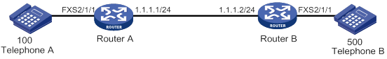
Configuration procedure
# Configure the local number as 100 for POTS entity 100, and bind FXS interface line 2/1/1 to the POTS entity.
<RouterA> system-view
[RouterA] voice-setup
[RouterA-voice] dial-program
[RouterA-voice-dial] entity 100 pots
[RouterA-voice-dial-entity100] match-template 100
[RouterA-voice-dial-entity100] line 2/1/1
[RouterA-voice-dial-entity100] quit
# Configure the called number as 300 for VoIP entity 300, and configure the destination IP address as 1.1.1.2.
[RouterA-voice-dial] entity 300 voip
[RouterA-voice-dial-entity300] match-template 300
[RouterA-voice-dial-entity300] address sip ip 1.1.1.2
[RouterA-voice-dial-entity300] outband sip
2. Configure Router B:
# Configure the local number as 500 for POTS entity 500, and bind FXS interface line 2/1/1 to the POTS entity.
<RouterB> system-view
[RouterB] voice-setup
[RouterB-voice] dial-program
[RouterB-voice-dial] entity 500 pots
[RouterB-voice-dial-entity500] match-template 500
[RouterB-voice-dial-entity500] line 2/1/1
[RouterB-voice-dial-entity500] quit
# Configure an access number of 300 for IVR entity 300, and specify node 10 as the root node.
[RouterB-voice-dial] entity 300 ivr
[RouterB-voice-dial-entity300] match-template 300
[RouterB-voice-dial-entity300] ivr-root 10
[RouterB-voice-dial-entity300] quit
[RouterB-voice-dial] quit
# Specify IDs for media files as follows:
? Specify ID 10001 for the file cfa0:/wav/g729r8/welcome.wav.
? Specify ID 10002 for the file cfa0:/wav/g729r8/timeout.wav.
? Specify ID 10003 for the file cfa0:/wav/g729r8/input_error.wav.
[RouterB-voice] media-file g729r8
[RouterB-voice-media-g729r8] set-media 10001 file cfa0:/wav/g729r8/welcome.wav
[RouterB-voice-media-g729r8] set-media 10002 file cfa0:/wav/g729r8/timeout.wav
[RouterB-voice-media-g729r8] set-media 10003 file cfa0:/wav/g729r8/input_error.wav
[RouterB-voice-media-g729r8] quit
# Configure global policies for handling input errors and timeouts.
[RouterB-voice-ivr] global-input-error repeat 3 media-play 10003
[RouterB-voice-ivr] global-timeout repeat 4 expires 5 media-play 10002
# Configure call node 10 as follows:
? After the IVR access number 300 is matched, Router B plays the media file welcome.wav.
? After the subscriber dials 0 at Telephone A, Router B automatically originates a call to Telephone B.
[RouterB-voice-ivr] node 10 call
[RouterB-voice-ivr-node10] media-play 10001
[RouterB-voice-ivr-node10] input 0 extension 500
Verifying the configuration
# Dial the number 300 at Telephone A to verify that the media file welcome.wav is played.
# After the media file welcome.wav is played, dial 0 at Telephone A to verify that Telephone B rings.
Jump node configuration example
Network requirements
As shown in Figure 83, configure an IVR access number and customize jump node functions on Router B to achieve the following purposes:
· After a subscriber dials 300 (the IVR access number of Router B) at Telephone A, Router B plays the media file welcome.wav. The subscriber performs jump operations according to the voice prompts. Then, after the subscriber presses the # key, Router B terminates the call.
· In the case of an input error, Router B plays the media file input_error.wav.
· In the case of an input timeout, Router B plays the media file timeout.wav.
Configuration procedure
# Configure the local number as 100 for POTS entity 100, and bind FXS interface line 2/1/1 to the POTS entity.
<RouterA> system-view
[RouterA] voice-setup
[RouterA-voice] dial-program
[RouterA-voice-dial] entity 100 pots
[RouterA-voice-dial-entity100] match-template 100
[RouterA-voice-dial-entity100] line 2/1/1
[RouterA-voice-dial-entity100] quit
# Configure the called number as 300 for VoIP entity 300, and configure the destination IP address as 1.1.1.2.
[RouterA-voice-dial] entity 300 voip
[RouterA-voice-dial-entity300] match-template 300
[RouterA-voice-dial-entity300] address sip ip 1.1.1.2
[RouterA-voice-dial-entity300] outband sip
2. Configure Router B:
# Configure the local number as 500 for POTS entity 500, and bind FXS interface line 2/1/1 to the POTS entity.
<RouterB> system-view
[RouterB] voice-setup
[RouterB-voice] dial-program
[RouterB-voice-dial] entity 500 pots
[RouterB-voice-dial-entity500] match-template 500
[RouterB-voice-dial-entity500] line 2/1/1
[RouterB-voice-dial-entity500] quit
# Configure an access number of 300 for IVR entity 300, and specify node 10 as the root node.
[RouterB-voice-dial] entity 300 ivr
[RouterB-voice-dial-entity300] match-template 300
[RouterB-voice-dial-entity300] ivr-root 10
[RouterB-voice-dial-entity300] quit
[RouterB-voice-dial] quit
# Specify IDs for media files as follows:
? Specify ID 10001 for the file cfa0:/wav/g729r8/welcome.wav.
? Specify ID 10002 for the file cfa0:/wav/g729r8/timeout.wav.
? Specify ID 10003 for the file cfa0:/wav/g729r8/input_error.wav.
[RouterB-voice] media-file g729r8
[RouterB-voice-media-g729r8] set-media 10001 file cfa0:/wav/g729r8/welcome.wav
[RouterB-voice-media-g729r8] set-media 10002 file cfa0:/wav/g729r8/timeout.wav
[RouterB-voice-media-g729r8] set-media 10003 file cfa0:/wav/g729r8/input_error.wav
[RouterB-voice-media-g729r8] quit
# Configure global policies for handling input errors and timeouts.
[RouterB-voice-ivr] global-input-error repeat 3 media-play 10003
[RouterB-voice-ivr] global-timeout repeat 4 expires 5 media-play 10002
# Configure jump node 10 as follows:
? After the IVR access number 300 is matched, Router B plays the media file welcome.wav.
? After the subscriber presses the key # at Telephone A, Router B terminates the call.
[RouterB-voice-ivr] node 10 jump
[RouterB-voice-ivr-node10] media-play 10001
[RouterB-voice-ivr-node10] user-input # end-call
Verify the configuration
# Dial the number 300 at Telephone A to verify that the media file welcome.wav is played.
# After the media file welcome.wav is played, dial # at Telephone A to verify that the call is terminated.
Service node configuration example 1
Network requirements
As shown in Figure 84, configure an IVR access number and customize service node functions on Router B to achieve the following purposes:
· After a subscriber dials 300 (the IVR access number of Router B) at Telephone A, Router B places an immediate secondary call to Telephone B.
· In the case of an input error, Router B plays the media file input_error.wav.
· In the case of an input timeout, Router B plays the media file timeout.wav.
Configuration procedure
1. Configure Router A:
# Configure the local number as 100 for POTS entity 100, and bind FXS interface line 2/1/1 to the POTS entity.
<RouterA> system-view
[RouterA] voice-setup
[RouterA-voice] dial-program
[RouterA-voice-dial] entity 100 pots
[RouterA-voice-dial-entity100] match-template 100
[RouterA-voice-dial-entity100] line 2/1/1
[RouterA-voice-dial-entity100] quit
# Configure the called number as 300 for VoIP entity 300, and configure the destination IP address as 1.1.1.2.
[RouterA-voice-dial] entity 300 voip
[RouterA-voice-dial-entity300] match-template 300
[RouterA-voice-dial-entity300] address sip ip 1.1.1.2
[RouterA-voice-dial-entity300] outband sip
2. Configure Router B:
# Configure the local number as 500 for POTS entity 500, and bind FXS interface line 2/1/1 to the POTS entity.
<RouterB> system-view
[RouterB] voice-setup
[RouterB-voice] dial-program
[RouterB-voice-dial] entity 500 pots
[RouterB-voice-dial-entity500] match-template 500
[RouterB-voice-dial-entity500] line 2/1/1
[RouterB-voice-dial-entity500] quit
# Configure an access number of 300 for IVR entity 300, and specify node 10 as the root node.
[RouterB-voice-dial] entity 300 ivr
[RouterB-voice-dial-entity300] match-template 300
[RouterB-voice-dial-entity300] ivr-root 10
[RouterB-voice-dial-entity300] quit
[RouterB-voice-dial] quit
# Specify IDs for media files as follows:
? Specify ID 10001 for the file cfa0:/wav/g729r8/welcome.wav.
? Specify ID 10002 for the file cfa0:/wav/g729r8/timeout.wav.
? Specify ID 10003 for the file cfa0:/wav/g729r8/input_error.wav.
[RouterB-voice] media-file g729r8
[RouterB-voice-media-g729r8] set-media 10001 file cfa0:/wav/g729r8/welcome.wav
[RouterB-voice-media-g729r8] set-media 10002 file cfa0:/wav/g729r8/timeout.wav
[RouterB-voice-media-g729r8] set-media 10003 file cfa0:/wav/g729r8/input_error.wav
[RouterB-voice-media-g729r8] quit
# Configure global policies for handling input errors and timeouts.
[RouterB-voice-ivr] global-input-error repeat 3 media-play 10003
[RouterB-voice-ivr] global-timeout repeat 4 expires 5 media-play 10002
# Configure Service node 10 execute the immediate secondary call to Telephone B (500) without playing the media file welcome.wav.
[RouterB-voice-ivr] node 10 service
[RouterB-voice-ivr-node10] operation 1 media-play 10001 1
[RouterB-voice-ivr-node10] operation 2 call-immediate 500
[RouterB-voice-ivr-node10] select-rule 2 1 3
Verifying the configuration
# Dial the number 300 at Telephone A to verify that Telephone B rings and the media file welcome.wav is not played.
Service node configuration example 2
Network requirements
As shown in Figure 85, configure an IVR access number and customize service node functions on Router B to achieve the following purposes:
· After a subscriber dials 300 (the IVR access number of Router B) at Telephone A, Router B plays the media file bye.wav and then terminates the call.
· In the case of an input error, Router B plays the media file input_error.wav.
· In the case of an input timeout, Router B plays the media file timeout.wav.
Configuration procedure
1. Configure Router A:
# Configure the local number as 100 for POTS entity 100, and bind FXS interface line 2/1/1 to the POTS entity.
<RouterA> system-view
[RouterA] voice-setup
[RouterA-voice] dial-program
[RouterA-voice-dial] entity 100 pots
[RouterA-voice-dial-entity100] match-template 100
[RouterA-voice-dial-entity100] line 2/1/1
[RouterA-voice-dial-entity100] quit
# Configure the called number as 300 for VoIP entity 300, and configure the destination IP address as 1.1.1.2.
[RouterA-voice-dial] entity 300 voip
[RouterA-voice-dial-entity300] match-template 300
[RouterA-voice-dial-entity300] address sip ip 1.1.1.2
[RouterA-voice-dial-entity300] outband sip
2. Configure Router B:
# Configure the local number as 500 for POTS entity 500, and bind FXS interface line 2/1/1 to the POTS entity.
<RouterB> system-view
[RouterB] voice-setup
[RouterB-voice] dial-program
[RouterB-voice-dial] entity 500 pots
[RouterB-voice-dial-entity500] match-template 500
[RouterB-voice-dial-entity500] line 2/1/1
[RouterB-voice-dial-entity500] quit
# Configure an access number of 300 for IVR entity 300, and specify node 10 as the root node.
[RouterB-voice-dial] entity 300 ivr
[RouterB-voice-dial-entity300] match-template 300
[RouterB-voice-dial-entity300] ivr-root 10
[RouterB-voice-dial-entity300] quit
[RouterB-voice-dial] quit
# Specify IDs for media files as follows:
? Specify ID 10002 for the file cfa0:/wav/g729r8/timeout.wav.
? Specify ID 10003 for the file cfa0:/wav/g729r8/input_error.wav.
? Specify ID 10004 for the file cfa0:/wav/g729r8/bye.wav.
[RouterB-voice] media-file g729r8
[RouterB-voice-media-g729r8] set-media 10002 file cfa0:/wav/g729r8/timeout.wav
[RouterB-voice-media-g729r8] set-media 10003 file cfa0:/wav/g729r8/input_error.wav
[RouterB-voice-media-g729r8] set-media 10004 file cfa0:/wav/g729r8/bye.wav
[RouterB-voice-media-g729r8] quit
# Configure global policies for handling input errors and timeouts.
[RouterB-voice-ivr] global-input-error repeat 3 media-play 10003
[RouterB-voice-ivr] global-timeout repeat 4 expires 5 media-play 10002
# Configure service node 10 to play the media file bye.wav and then terminate the call.
[RouterB-voice-ivr] node 10 service
[RouterB-voice-ivr-node10] operation 2 end-call
[RouterB-voice-ivr-node10] operation 3 media-play 10004 1
[RouterB-voice-ivr-node10] select-rule 3 2 1
Verifying the configuration
# Dial the number 300 at Telephone A to verify that Router B plays the media file bye.wav and then terminates the call.
Comprehensive IVR node configuration example
Network requirements
As shown in Figure 86, configure an IVR access number and customize call node, jump node and service node functions on Router B to achieve the following purposes:
· After a subscriber dials 300 (the IVR access number of Router B) at Telephone A, Router B plays the media file welcome.wav.
? If the subscriber presses the * key at Telephone A, the call jumps to the service node and the subscriber hears voice prompts of the media file bye.wav. Then, the service node releases the call.
? If the subscriber presses the # key at Telephone A, the call jumps to the call node and the subscriber hears the voice prompts of the media file call.wav. Then, if the subscriber dials 1, the call node executes an extension secondary call to Telephone B (500).
Configuration procedure
1. Configure Router A:
# Configure the local number as 100 for POTS entity 100, and bind FXS interface line 2/1/1 to the POTS entity.
<RouterA> system-view
[RouterA] voice-setup
[RouterA-voice] dial-program
[RouterA-voice-dial] entity 100 pots
[RouterA-voice-dial-entity100] match-template 100
[RouterA-voice-dial-entity100] line 2/1/1
[RouterA-voice-dial-entity100] quit
# Configure the called number as 300 for VoIP entity 300, and configure the destination IP address as 1.1.1.2.
[RouterA-voice-dial] entity 300 voip
[RouterA-voice-dial-entity300] match-template 300
[RouterA-voice-dial-entity300] address sip ip 1.1.1.2
[RouterA-voice-dial-entity300] outband sip
2. Configure Router B:
# Configure the local number as 500 for POTS entity 500, and bind FXS interface line 2/1/1 to the POTS entity.
<RouterB> system-view
[RouterB] voice-setup
[RouterB-voice] dial-program
[RouterB-voice-dial] entity 500 pots
[RouterB-voice-dial-entity500] match-template 500
[RouterB-voice-dial-entity500] line 2/1/1
[RouterB-voice-dial-entity500] quit
[RouterB-voice-dial] quit
# Configure an access number of 300 for IVR entity 300, and specify node 1 as the root node.
[RouterB-voice-dial] entity 300 ivr
[RouterB-voice-dial-entity300] match-template 300
[RouterB-voice-dial-entity300] ivr-root 1
[RouterB-voice-dial-entity300] quit
[RouterB-voice-dial] quit
# Specify IDs for media files as follows:
? Specify ID 10001 for the file cfa0:/wav/g729r8/welcome.wav.
? Specify ID 10002 for the file cfa0:/wav/g729r8/timeout.wav.
? Specify ID 10003 for the file cfa0:/wav/g729r8/input_error.wav.
? Specify ID 10004 for the file cfa0:/wav/g729r8/bye.wav.
? Specify ID 10005 for the file cfa0:/wav/g729r8/call.wav.
[RouterB-voice] media-file g729r8
[RouterB-voice-media-g729r8] set-media 10001 file cfa0:/wav/g729r8/welcome.wav
[RouterB-voice-media-g729r8] set-media 10002 file cfa0:/wav/g729r8/timeout.wav
[RouterB-voice-media-g729r8] set-media 10003 file cfa0:/wav/g729r8/input_error.wav
[RouterB-voice-media-g729r8] set-media 10004 file cfa0:/wav/g729r8/bye.wav
[RouterB-voice-media-g729r8] set-media 10005 file cfa0:/wav/g729r8/call.wav
[RouterB-voice-media-g729r8] quit
# Configure global policies for handling input errors and timeouts.
[RouterB-voice-ivr] global-input-error repeat 3 media-play 10003
[RouterB-voice-ivr] global-timeout repeat 4 expires 5 media-play 10002
# Configure jump node 1 as follows:
? Play the media file welcome.wav after the IVR access number 300 is matched.
? Jump to node 20 if the subscriber presses the * key at Telephone A after the play of the media file welcome.wav ends.
? Jump to node 10 if the subscriber presses the # key at Telephone A after the play of the media file welcome.wav ends.
[RouterB-voice-ivr] node 1 jump
[RouterB-voice-ivr-node1] user-input # goto-node 10
[RouterB-voice-ivr-node1] user-input * goto-node 20
[RouterB-voice-ivr-node1] media-play 10001 force
[RouterB-voice-ivr-node1] quit
# Configure call node 10 as follows:
? First play the media file call.wav.
? Originate a call to number 500 if the subscriber dials 1 at Telephone A after the play of the media file call.wav ends.
[RouterB-voice-ivr] node 10 call
[RouterB-voice-ivr-node10] media-play 10005 force
[RouterB-voice-ivr-node10] input 1 extension 500
[RouterB-voice-ivr-node10] quit
# Configure service node 20 to play the media file bye.wav and then terminate the call.
[RouterB-voice-ivr] node 20 service
[RouterB-voice-ivr-node20] operation 2 media-play 10004
[RouterB-voice-ivr-node20] operation 3 end-call
[RouterB-voice-ivr-node20] select-rule 2 3 1
Verifying the configuration
# Dial the number 300 at Telephone A to verify that Router B plays the media file welcome.wav.
# After the media file welcome.wav is played, dial the * key at Telephone A to verify that the call jumps to node 20. (You hear the voice prompt of the media file bye.wav and then hear busy tones.)
# After the media file welcome.wav is played, dial the # key at Telephone A to verify that the call jumps to node 10. (You hear the voice prompt of the media file call.wav.)
# After the media file call.wav is played, dial 1 at Telephone A to verify that the node originates an extension secondary call to number 500 and Telephone B rings.
Troubleshooting IVR
Invalid node
Symptom
A subscriber dials the IVR access number 300, and the voice prompt is played. According to the voice prompt, the subscriber presses the # key to originate a secondary call, but the call is terminated. Following are the configurations:
[Sysname-voice-dial] entity 300 ivr
[Sysname-voice-dial-entity300] match-template 300
[Sysname-voice-dial-entity300] ivr-root 1
[Sysname-voice-dial-entity300] quit
[Sysname-voice-dial] quit
[Sysname-voice] ivr-system
[Sysname-voice-ivr] node 1 jump
[Sysname-voice-ivr-node1] user-input # goto-node 10
[Sysname-voice-ivr-node1] user-input * goto-node 20
[Sysname-voice-ivr-node1] media-play 10001 force
[Sysname-voice-ivr-node1] quit
[Sysname-voice-ivr] node 10 call
Analysis
After the subscriber presses the # key, the call jumps to node 10 and is terminated because node 10 does not contain any operations.
Solution
To resolve the problem:
1. Configure node 10 to play a media file.
2. Configure a number match mode for node 10 to place normal secondary calls.
3. If the problem persists, contact H3C Support.
Loopback node
Symptom
A subscriber dials the IVR access number 300 and presses the # key to jump to node 10, but the call is terminated.
Following are the configurations:
[Sysname-voice-dial] entity 300 ivr
[Sysname-voice-dial-entity300] match-template 300
[Sysname-voice-dial-entity300] ivr-root 1
[Sysname-voice-dial-entity300] quit
[Sysname-voice-dial] quit
[Sysname-voice] ivr-system
[Sysname-voice-ivr] node 1 jump
[Sysname-voice-ivr-node1] user-input # goto-node 10
[Sysname-voice-ivr-node1] quit
[Sysname-voice-ivr] node 10 service
[Sysname-voice-ivr-node10] operation 1 goto-node 11
[Sysname-voice-ivr-node10] quit
[Sysname-voice-ivr] node 11 service
[Sysname-voice-ivr-node11] operation 1 goto-node 12
[Sysname-voice-ivr-node11] quit
[Sysname-voice-ivr] node 12 service
[Sysname-voice-ivr-node12] operation 1 goto-node 10
Analysis
After the # key is pressed, the IVR process jumps to node 10, and then jumps to node 11, node 12, and jumps back to node 10 again. Node 10 is the loopback node that causes the termination of the call.
Solution
To resolve the problem:
1. Modify the configuration for node 10, such as configuring a calling operation for it.
2. If the problem persists, contact H3C Support.
Node depth exceeds eight levels
Symptom
When the IVR process jumps to node 8, the call is terminated.
Following are the configurations:
[Sysname-voice-dial] entity 300 ivr
[Sysname-voice-dial-entity300] match-template 300
[Sysname-voice-dial-entity300] ivr-root 1
[Sysname-voice-dial-entity300] quit
[Sysname-voice-dial] quit
[Sysname-voice] ivr-system
[Sysname-voice-ivr] node 1 jump
[Sysname-voice-ivr-node1] user-input # goto-node 2
[Sysname-voice-ivr-node1] quit
[Sysname-voice-ivr] node 2 jump
[Sysname-voice-ivr-node2] user-input # goto-node 3
[Sysname-voice-ivr-node2] quit
[Sysname-voice-ivr] node 3 jump
[Sysname-voice-ivr-node3] user-input # goto-node 4
[Sysname-voice-ivr-node3] quit
[Sysname-voice-ivr] node 4 jump
[Sysname-voice-ivr-node4] user-input # goto-node 5
[Sysname-voice-ivr-node4] quit
[Sysname-voice-ivr] node 5 jump
[Sysname-voice-ivr-node5] user-input # goto-node 6
[Sysname-voice-ivr-node5] quit
[Sysname-voice-ivr] node 6 jump
[Sysname-voice-ivr-node6] user-input # goto-node 7
[Sysname-voice-ivr-node6] quit
[Sysname-voice-ivr] node 7 jump
[Sysname-voice-ivr-node7] user-input # goto-node 8
[Sysname-voice-ivr-node7] quit
[Sysname-voice-ivr] node 8 jump
[Sysname-voice-ivr-node8] user-input # goto-node 9
[Sysname-voice-ivr-node8] quit
[Sysname-voice-ivr] node 9 call
[Sysname-voice-ivr-node9] extension 1 call 300
[Sysname-voice-ivr-node9] quit
Analysis
When the IVR process jumps to node 8, it has already executed eight nodes. The eight-level limit is reached, and the call is terminated.
Solution
To resolve the problem:
1. Reduce the IVR process jumps to a value less than eight.
2. If the problem persists, contact H3C Support.
Matching mistake I
Symptom
A node is configured to execute both a normal secondary call by exactly matching the called number and an extension secondary call. When the subscriber dials 1201, the node does not execute the secondary call to the number 7745231.
Following are the configurations:
[Sysname-voice-ivr] node 1 call
[Sysname-voice-ivr-node1] call-normal matching
[Sysname-voice-ivr-node1] input 1201 extension 7745231
Analysis
There are short numbers for special usage, such as 120, 110, and 114. When the subscriber dials the input number, the node executes a normal secondary call to the short number.
Solution
To resolve the problem:
1. Change the prefixes of input numbers for extension secondary calls to numbers other than special short numbers.
2. If the problem persists, contact H3C Support.
Matching mistake 2
Symptom
A node is configured to execute both a normal secondary call by matching number before the terminator # and an extension secondary call. When the subscriber dials the number 774566, the node always connects the subscriber to the number 7745231.
Following are the configurations:
[Sysname-voice-ivr] node 1 call
[Sysname-voice-ivr-node1] call-normal terminator #
[Sysname-voice-ivr-node1] input 7 extension 7745231
Analysis
When the dialed number matches both the extension secondary call and the normal secondary call, the system places the extension secondary call. When the subscriber dials the number 7, the node matches it with the extension number 7, and connects the subscriber to the number 7745231 instead of 7745666.
Solution
To resolve the problem:
1. Change the extension number 7 to *7.
2. Change the matching terminator of the normal secondary call to a character other than an asterisk (*).
3. If the problem persists, contact H3C Support.
Adjusting parameters for analog voice interfaces,18
Adjusting parameters for digital voice interfaces,48
Advantages,202
Analog voice interface configuration examples,23
Background,132
Binding a digital voice interface to a POTS entity,47
Binding an FXS interface to an FXO interface,12
Call services configuration examples,144
Call services configuration task list,142
Compatibility information,30
Compatibility information,1
Configuration task list,2
Configuration task list,76
Configuration task list,58
Configuration task lists,31
Configuring a BSV interface,35
Configuring a dial prefix,91
Configuring a number match mode,79
Configuring a number sending mode,88
Configuring a POTS entity,58
Configuring a priority for a voice entity,88
Configuring a SIP trunk account,135
Configuring a timeslot set,35
Configuring a trusted node,107
Configuring a voice server,169
Configuring a VoIP entity,64
Configuring an E&M interface,13
Configuring an FXO interface,6
Configuring an FXS interface,4
Configuring an IVR entity,69
Configuring an IVR entity,203
Configuring an IVR node,204
Configuring basic calling,172
Configuring basic parameters for a T1 interface,33
Configuring basic parameters for an E1 interface,32
Configuring basic settings,3
Configuring basic settings,32
Configuring call forwarding,142
Configuring call progress tones,3
Configuring call services supported by SRST,173
Configuring caller control,76
Configuring caller group control,78
Configuring DTMF signaling,17
Configuring extended SIP functions,108
Configuring fax pass-through,160
Configuring global handling policies,204
Configuring INVITE retransmission,107
Configuring modem pass-through,161
Configuring MWI,143
Configuring number substitution,81
Configuring out-of-dialog keepalive for a VoIP entity,106
Configuring QSIG tunneling over SIP-T,120
Configuring R2 signaling,36
Configuring reverse charging,47
Configuring SIP security,116
Configuring SIP UA registration,101
Configuring the call destination address for a VoIP entity,105
Configuring the call hold mode,142
Configuring the fax protocol,157
Configuring the ISDN protocol,46
Configuring the maximum number of calls allowed by a voice entity,81
Configuring the voice entity selection order,88
Configuring transport protocols for SIP calls,115
Customizable IVR configuration examples,207
Customizable IVR configuration task list,203
Dial program configuration examples,91
Digital voice interface configuration examples,50
Displaying and maintaining analog voice interfaces,22
Displaying and maintaining customizable IVR,207
Displaying and maintaining digital voice interfaces,50
Displaying and maintaining SIP,121
Displaying and maintaining SIP trunk,136
Displaying and maintaining SRST,179
Displaying and maintaining voice entities,75
Enabling codec transparent transmission,135
Enabling DO-EO conversion,136
Enabling media flow-around,136
Enabling private line auto ring-down,79
Enabling SIP logging,74
Enabling SIP-to-SIP calling,135
Enabling the router to treat DISCONNECT messages with PI 8 as standard DISCONNECT messages,47
Fax transmission flow,156
Feature and hardware compatibility,57
Feature and hardware compatibility,76
Feature and hardware compatibility,203
Feature and hardware compatibility,156
Feature and hardware compatibility,141
Feature and hardware compatibility,100
Feature and hardware compatibility,134
Feature and hardware compatibility,168
Features,133
FoIP configuration examples,161
FoIP configuration task list,157
Overview,57
Overview,30
Overview,164
Overview,98
Overview,202
Overview,139
Overview,1
Protocols and standards,134
Setting the global DSCP value,120
Setting the maximum duration of DSP-buffered data,74
Setting the RTP timeout period,74
SIP configuration task list,101
SIP trunk configuration examples,137
SIP trunk configuration task list,134
SIP UA configuration examples,122
Specifying a URL scheme,119
Specifying an ID for a media file,204
SRST configuration examples,179
SRST configuration task list,168
Troubleshooting IVR,220
Typical applications,133