- Table of Contents
- Related Documents
-
| Title | Size | Download |
|---|---|---|
| 01-Text | 1.11 MB |
Contents
Command and hardware compatibility
Configuration restrictions and guidelines
Configuring an IPv4 advanced ACL
Configuring an IPv6 advanced ACL
Configuring packet filtering with ACLs
Applying an ACL to an interface for packet filtering
Applying an ACL to a zone pair for packet filtering
Configuring logging and SNMP notifications for packet filtering
Setting the packet filtering default action
Displaying and maintaining ACLs
Interface-based packet filter configuration example
Zone pair-based packet filter configuration example
QoS processing flow in a device
Command and hardware compatibility
Configuration procedure diagram
Command and hardware compatibility
Applying the QoS policy to an interface or PVC
Applying the QoS policy to a PW
Applying the QoS policy to a control plane
Applying the QoS policy to the management interface control plane
Applying the QoS policy to a user profile
Setting the QoS policy-based traffic rate statistics collection period for an interface
Displaying and maintaining QoS policies
Priority mapping configuration tasks
Configuring a port to trust packet priority for priority mapping
Changing the port priority of an interface
Displaying and maintaining priority mapping
Priority mapping configuration examples
Priority trust mode configuration example
Priority mapping table and priority marking configuration example
Configuring traffic policing, GTS, and rate limit
Traffic evaluation and token buckets
Command and hardware compatibility
Configuring traffic policing by using the MQC approach
Configuring traffic policing by using the non-MQC approach
Configuring GTS by using the MQC approach
Configuring GTS by using the non-MQC approach
Configuring the rate limit for an interface
Configuring the rate limit for a PW
Displaying and maintaining traffic policing, GTS, and rate limit
Traffic policing, GTS, and rate limit configuration examples
Traffic policing and GTS configuration example
Per-IP-address traffic policing configuration example
Configuring congestion management
Congestion management technique comparison
Command and hardware compatibility
Setting the FIFO queue size for an interface or PVC
Setting the FIFO queue size for a PW
Configuration restrictions and guidelines
Configuration restrictions and guidelines
Configuring WFQ for an interface or PVC
Predefined classes, traffic behaviors, and policies
Setting the maximum available interface bandwidth
Setting the maximum reserved bandwidth as a percentage of available bandwidth
Enabling packet information pre-extraction
Displaying and maintaining congestion management
Configuring congestion avoidance
Relationship between WRED and queuing mechanisms
Configuring WRED on an interface
Displaying and maintaining WRED
Configuring traffic redirecting
Feature and hardware compatibility
Configuring basic BGP functions
Configuring the route receiver
Configuring basic BGP functions
Enabling QPPB on the route receiving interface
Applying the QoS policy to an interface
QPPB configuration example in an IPv4 network
QPPB configuration example in an MPLS L3VPN
QPPB configuration example in an IPv6 network
Appendix B Default priority maps
Appendix C Introduction to packet precedences
Configuring MPLS priority marking
MPLS QoS configuration example
Feature and hardware compatibility
FR QoS configuration task list
Creating and configuring an FR class
Configuration restrictions and guidelines
Configuration restrictions and guidelines
Configuring PVC queuing as FIFO, PQ, CQ, WFQ, or RTPQ
Configuring PVC queuing as CBQ
Configuring interface queuing as PVC PQ
Configuring an FR DE rule list
Configuring Frame Relay FRF.12 fragmentation for an FR class
Displaying and maintaining FR QoS
Displaying and maintaining time ranges
Time range configuration example
Configuring ACLs
Overview
An access control list (ACL) is a set of rules for identifying traffic based on criteria such as source IP address, destination IP address, and port number. The rules are also called permit or deny statements.
ACLs are primarily used for packet filtering. "Configuring packet filtering with ACLs" provides an example. You can use ACLs in QoS, security, routing, and other modules for identifying traffic. The packet drop or forwarding decisions depend on the modules that use ACLs.
ACL types
|
Type |
ACL number |
IP version |
Match criteria |
|
Basic ACLs |
2000 to 2999 |
IPv4 |
Source IPv4 address. |
|
IPv6 |
Source IPv6 address. |
||
|
Advanced ACLs |
3000 to 3999 |
IPv4 |
Source IPv4 address, destination IPv4 address, packet priority, protocol number, and other Layer 3 and Layer 4 header fields. |
|
IPv6 |
Source IPv6 address, destination IPv6 address, packet priority, protocol number, and other Layer 3 and Layer 4 header fields. |
||
|
Layer 2 ACLs |
4000 to 4999 |
IPv4 and IPv6 |
Layer 2 header fields, such as source and destination MAC addresses, 802.1p priority, and link layer protocol type. |
Numbering and naming ACLs
When creating an ACL, you must assign it a number or name for identification. You can specify an existing ACL by its number or name. Each ACL type has a unique range of ACL numbers.
For basic or advanced ACLs with the same number, you must use the ipv6 keyword to distinguish them. For ACLs with the same name, you must use the ipv6 and mac keywords to distinguish them.
Match order
The rules in an ACL are sorted in a specific order. When a packet matches a rule, the device stops the match process and performs the action defined in the rule. If an ACL contains overlapping or conflicting rules, the matching result and action to take depend on the rule order.
The following ACL match orders are available:
· config—Sorts ACL rules in ascending order of rule ID. A rule with a lower ID is matched before a rule with a higher ID. If you use this method, check the rules and their order carefully.
· auto—Sorts ACL rules in depth-first order. Depth-first ordering makes sure any subset of a rule is always matched before the rule. Table 1 lists the sequence of tie breakers that depth-first ordering uses to sort rules for each type of ACL.
Table 1 Sort ACL rules in depth-first order
|
ACL type |
Sequence of tie breakers |
|
IPv4 basic ACL |
1. VPN instance. 2. More 0s in the source IPv4 address wildcard (more 0s means a narrower IPv4 address range). 3. Rule configured earlier. |
|
IPv4 advanced ACL |
1. VPN instance. 2. Specific protocol number. 3. More 0s in the source IPv4 address wildcard mask. 4. More 0s in the destination IPv4 address wildcard. 5. Narrower TCP/UDP service port number range. 6. Rule configured earlier. |
|
IPv6 basic ACL |
1. VPN instance. 2. Longer prefix for the source IPv6 address (a longer prefix means a narrower IPv6 address range). 3. Rule configured earlier. |
|
IPv6 advanced ACL |
1. VPN instance. 2. Specific protocol number. 3. Longer prefix for the source IPv6 address. 4. Longer prefix for the destination IPv6 address. 5. Narrower TCP/UDP service port number range. 6. Rule configured earlier. |
|
Layer 2 ACL |
1. More 1s in the source MAC address mask (more 1s means a smaller MAC address). 2. More 1s in the destination MAC address mask. 3. Rule configured earlier. |
A wildcard mask, also called an inverse mask, is a 32-bit binary number represented in dotted decimal notation. In contrast to a network mask, the 0 bits in a wildcard mask represent "do care" bits, and the 1 bits represent "don't care" bits. If the "do care" bits in an IP address are identical to the "do care" bits in an IP address criterion, the IP address matches the criterion. All "don't care" bits are ignored. The 0s and 1s in a wildcard mask can be noncontiguous. For example, 0.255.0.255 is a valid wildcard mask.
Rule numbering
ACL rules can be manually numbered or automatically numbered. This section describes how automatic ACL rule numbering works.
Rule numbering step
If you do not assign an ID to the rule you are creating, the system automatically assigns it a rule ID. The rule numbering step sets the increment by which the system automatically numbers rules. For example, the default ACL rule numbering step is 5. If you do not assign IDs to rules you are creating, they are automatically numbered 0, 5, 10, 15, and so on. The wider the numbering step, the more rules you can insert between two rules.
By introducing a gap between rules rather than contiguously numbering rules, you have the flexibility of inserting rules in an ACL. This feature is important for a config-order ACL, where ACL rules are matched in ascending order of rule ID.
Automatic rule numbering and renumbering
The ID automatically assigned to an ACL rule takes the nearest higher multiple of the numbering step to the current highest rule ID, starting with 0.
For example, if the step is 5, and there are five rules numbered 0, 5, 9, 10, and 12, the newly defined rule is numbered 15. If the ACL does not contain a rule, the first rule is numbered 0.
Whenever the step changes, the rules are renumbered, starting from 0. For example, changing the step from 5 to 2 renumbers rules 5, 10, 13, and 15 as rules 0, 2, 4, and 6.
Fragment filtering with ACLs
Traditional packet filtering matches only first fragments of packets, and allows all subsequent non-first fragments to pass through. Attackers can fabricate non-first fragments to attack networks.
To avoid risks, the ACL feature is designed as follows:
· Filters all fragments by default, including non-first fragments.
· Allows for matching criteria modification for efficiency. For example, you can configure the ACL to filter only non-first fragments.
Command and hardware compatibility
Commands and descriptions for centralized devices apply to the following routers:
· MSR810/810-W/810-W-DB/810-LM/810-W-LM/810-10-PoE/810-LM-HK/810-W-LM-HK/810-LMS/810-LUS.
· MSR2600-6-X1/2600-10-X1.
· MSR 2630.
· MSR3600-28/3600-51.
· MSR3600-28-SI/3600-51-SI.
· MSR3610-X1/3610-X1-DP/3610-X1-DC/3610-X1-DP-DC.
· MSR 3610/3620/3620-DP/3640/3660.
· MSR810-LM-GL/810-W-LM-GL/830-6EI-GL/830-10EI-GL/830-6HI-GL/830-10HI-GL/2600-6-X1-GL/3600-28-SI-GL.
Commands and descriptions for distributed devices apply to the following routers:
· MSR5620.
· MSR 5660.
· MSR 5680.
IPv6-related parameters are not supported on the following routers:
· MSR810/810-W/810-W-DB/810-LM/810-W-LM/810-10-PoE/810-LM-HK/810-W-LM-HK/810-LMS/810-LUS.
· MSR3600-28-SI/3600-51-SI.
Configuration restrictions and guidelines
Matching packets are forwarded through slow forwarding if an ACL rule contains match criteria or has functions enabled in addition to the following match criteria and functions:
· Source and destination IP addresses.
· Source and destination ports.
· Transport layer protocol.
· ICMP or ICMPv6 message type, message code, and message name.
· VPN instance.
· Logging.
· Time range.
Slow forwarding requires packets to be sent to the control plane for forwarding entry calculation, which affects the device forwarding performance.
Configuration task list
|
Tasks at a glance |
|
(Required.) Perform one or more of the following tasks: |
|
(Optional.) Copying an ACL |
|
(Optional.) Configuring packet filtering with ACLs |
|
(Optional.) Enabling ACL acceleration |
Configuring a basic ACL
This section describes procedures for configuring IPv4 and IPv6 basic ACLs.
Configuring an IPv4 basic ACL
IPv4 basic ACLs match packets based only on source IP addresses.
To configure an IPv4 basic ACL:
|
Step |
Command |
Remarks |
|
1. Enter system view. |
system-view |
N/A |
|
2. Create an IPv4 basic ACL and enter its view. |
acl basic { acl-number | name acl-name } [ match-order { auto | config } ] |
By default, no ACLs exist. The value range for a numbered IPv4 basic ACL is 2000 to 2999. Use the acl basic acl-number command to enter the view of a numbered IPv4 basic ACL. Use the acl basic name acl-name command to enter the view of a named IPv4 basic ACL. |
|
3. (Optional.) Configure a description for the IPv4 basic ACL. |
description text |
By default, an IPv4 basic ACL does not have a description. |
|
4. (Optional.) Set the rule numbering step. |
step step-value |
By default, the rule numbering step is 5 and the start rule ID is 0. |
|
5. Create or edit a rule. |
rule [ rule-id ] { deny | permit } [ counting | fragment | logging | source { object-group address-group-name | source-address source-wildcard | any } | time-range time-range-name | vpn-instance vpn-instance-name ] * |
By default, no IPv4 basic ACL rules exist. The logging keyword takes effect only when the module (for example, packet filtering) that uses the ACL supports logging. Support for the object-group address-group-name option depends on the device model. For more information, see ACL and QoS Command Reference. |
|
6. (Optional.) Add or edit a rule comment. |
rule rule-id comment text |
By default, no rule comment is configured. |
Configuring an IPv6 basic ACL
IPv6 basic ACLs match packets based only on source IP addresses.
To configure an IPv6 basic ACL:
|
Step |
Command |
Remarks |
|
1. Enter system view. |
system-view |
N/A |
|
2. Create an IPv6 basic ACL view and enter its view. |
acl ipv6 basic { acl-number | name acl-name } [ match-order { auto | config } ] |
By default, no ACLs exist. The value range for a numbered IPv6 basic ACL is 2000 to 2999. Use the acl ipv6 basic acl-number command to enter the view of a numbered IPv6 basic ACL. Use the acl ipv6 basic name acl-name command to enter the view of a named IPv6 basic ACL. |
|
3. (Optional.) Configure a description for the IPv6 basic ACL. |
description text |
By default, an IPv6 basic ACL does not have a description. |
|
4. (Optional.) Set the rule numbering step. |
step step-value |
By default, the rule numbering step is 5 and the start rule ID is 0. |
|
5. Create or edit a rule. |
rule [ rule-id ] { deny | permit } [ counting | fragment | logging | routing [ type routing-type ] | source { object-group address-group-name | source-address source-prefix | source-address/source-prefix | any } | time-range time-range-name | vpn-instance vpn-instance-name ] * |
By default, no IPv6 basic ACL rules exist. The logging keyword takes effect only when the module (for example, packet filtering) that uses the ACL supports logging. Support for the object-group address-group-name option depends on the device model. For more information, see ACL and QoS Command Reference. |
|
6. (Optional.) Add or edit a rule comment. |
rule rule-id comment text |
By default, no rule comment is configured. |
Configuring an advanced ACL
This section describes procedures for configuring IPv4 and IPv6 advanced ACLs.
Configuring an IPv4 advanced ACL
IPv4 advanced ACLs match packets based on the following criteria:
· Source IP addresses.
· Destination IP addresses.
· Packet priorities.
· Protocol numbers.
· Other protocol header information, such as TCP/UDP source and destination port numbers, TCP flags, ICMP message types, and ICMP message codes.
Compared to IPv4 basic ACLs, IPv4 advanced ACLs allow more flexible and accurate filtering.
To configure an IPv4 advanced ACL:
|
Step |
Command |
Remarks |
|
1. Enter system view. |
system-view |
N/A |
|
2. Create an IPv4 advanced ACL and enter its view. |
acl advanced { acl-number | name acl-name } [ match-order { auto | config } ] |
By default, no ACLs exist. The value range for a numbered IPv4 advanced ACL is 3000 to 3999. Use the acl advanced acl-number command to enter the view of a numbered IPv4 advanced ACL. Use the acl advanced name acl-name command to enter the view of a named IPv4 advanced ACL. |
|
3. (Optional.) Configure a description for the IPv4 advanced ACL. |
description text |
By default, an IPv4 advanced ACL does not have a description. |
|
4. (Optional.) Set the rule numbering step. |
step step-value |
By default, the rule numbering step is 5 and the start rule ID is 0. |
|
5. Create or edit a rule. |
rule [ rule-id ] { deny | permit } protocol [ { { ack ack-value | fin fin-value | psh psh-value | rst rst-value | syn syn-value | urg urg-value } * | established } | counting | destination { object-group address-group-name | dest-address dest-wildcard | any } | destination-port { object-group port-group-name | operator port1 [ port2 ] } | { dscp dscp1 [ to dscp2 ] | { precedence precedence | tos tos } * } | fragment | icmp-type { icmp-type [ icmp-code ] | icmp-message } | logging | source { object-group address-group-name | source-address source-wildcard | any } | source-port { object-group port-group-name | operator port1 [ port2 ] } | time-range time-range-name | vpn-instance vpn-instance-name ] * |
By default, no IPv4 advanced ACL rules exist. The logging keyword takes effect only when the module (for example, packet filtering) that uses the ACL supports logging. Support for the object-group parameter depends on the device model. For more information, see ACL and QoS Command Reference. |
|
6. (Optional.) Add or edit a rule comment. |
rule rule-id comment text |
By default, no rule comment is configured. |
Configuring an IPv6 advanced ACL
IPv6 advanced ACLs match packets based on the following criteria:
· Source IPv6 addresses.
· Destination IPv6 addresses.
· Packet priorities.
· Protocol numbers.
· Other protocol header fields such as the TCP/UDP source port number, TCP/UDP destination port number, ICMPv6 message type, and ICMPv6 message code.
Compared to IPv6 basic ACLs, IPv6 advanced ACLs allow more flexible and accurate filtering.
To configure an IPv6 advanced ACL:
|
Step |
Command |
Remarks |
|
1. Enter system view. |
system-view |
N/A |
|
2. Create an IPv6 advanced ACL and enter its view. |
acl ipv6 advanced { acl-number | name acl-name } [ match-order { auto | config } ] |
By default, no ACLs exist. The value range for a numbered IPv6 advanced ACL is 3000 to 3999. Use the acl ipv6 advanced acl-number command to enter the view of a numbered IPv6 advanced ACL. Use the acl ipv6 advanced name acl-name command to enter the view of a named IPv6 advanced ACL. |
|
3. (Optional.) Configure a description for the IPv6 advanced ACL. |
description text |
By default, an IPv6 advanced ACL does not have a description. |
|
4. (Optional.) Set the rule numbering step. |
step step-value |
By default, the rule numbering step is 5 and the start rule ID is 0. |
|
5. Create or edit a rule. |
rule [ rule-id ] { deny | permit } protocol [ { { ack ack-value | fin fin-value | psh psh-value | rst rst-value | syn syn-value | urg urg-value } * | established } | counting | destination { object-group address-group-name | dest-address dest-prefix | dest-address/dest-prefix | any } | destination-port { object-group port-group-name | operator port1 [ port2 ] } | dscp dscp | flow-label flow-label-value | fragment | icmp6-type { icmp6-type icmp6-code | icmp6-message } | logging | routing [ type routing-type ] | hop-by-hop [ type hop-type ] | source { object-group address-group-name | source-address source-prefix | source-address/source-prefix | any } | source-port { object-group port-group-name | operator port1 [ port2 ] } | time-range time-range-name | vpn-instance vpn-instance-name ] * |
By default, no IPv6 advanced ACL rules exist. The logging keyword takes effect only when the module (for example, packet filtering) that uses the ACL supports logging. Support for the object-group parameter depends on the device model. For more information, see ACL and QoS Command Reference. |
|
6. (Optional.) Add or edit a rule comment. |
rule rule-id comment text |
By default, no rule comment is configured. |
Configuring a Layer 2 ACL
Layer 2 ACLs, also called "Ethernet frame header ACLs," match packets based on Layer 2 Ethernet header fields, such as:
· Source MAC address.
· Destination MAC address.
· 802.1p priority (VLAN priority).
· Link layer protocol type.
To configure a Layer 2 ACL:
|
Step |
Command |
Remarks |
|
1. Enter system view. |
system-view |
N/A |
|
2. Create a Layer 2 ACL and enter its view. |
acl mac { acl-number | name acl-name } [ match-order { auto | config } ] |
By default, no ACLs exist. The value range for a numbered Layer 2 ACL is 4000 to 4999. Use the acl mac acl-number command to enter the view of a numbered Layer 2 ACL. Use the acl mac name acl-name command to enter the view of a named Layer 2 ACL. |
|
3. (Optional.) Configure a description for the Layer 2 ACL. |
description text |
By default, a Layer 2 ACL does not have a description. |
|
4. (Optional.) Set the rule numbering step. |
step step-value |
By default, the rule numbering step is 5 and the start rule ID is 0. |
|
5. Create or edit a rule. |
rule [ rule-id ] { deny | permit } [ cos dot1p | counting | dest-mac dest-address dest-mask | { lsap lsap-type lsap-type-mask | type protocol-type protocol-type-mask } | source-mac source-address source-mask | time-range time-range-name ] * |
By default, no Layer 2 ACL rules exist. |
|
6. (Optional.) Add or edit a rule comment. |
rule rule-id comment text |
By default, no rule comment is configured. |
Copying an ACL
You can create an ACL by copying an existing ACL (source ACL). The new ACL (destination ACL) has the same properties and content as the source ACL, but uses a different number or name than the source ACL.
To successfully copy an ACL, make sure:
· The destination ACL number is from the same type as the source ACL number.
· The source ACL already exists, but the destination ACL does not.
To copy an ACL:
|
Step |
Command |
|
1. Enter system view. |
system-view |
|
2. Copy an existing ACL to create a new ACL. |
acl [ ipv6 | mac ] copy { source-acl-number | name source-acl-name } to { dest-acl-number | name dest-acl-name } |
Configuring packet filtering with ACLs
This section describes procedures for applying an ACL to filter incoming or outgoing IPv4 or IPv6 packets on the specified interface.
Applying an ACL to an interface for packet filtering
|
Step |
Command |
Remarks |
|
1. Enter system view. |
system-view |
N/A |
|
2. Enter interface view. |
interface interface-type interface-number |
Layer 2 interfaces are not supported. |
|
3. Apply an ACL to the interface to filter packets. |
packet-filter [ ipv6 | mac ] { acl-number | name acl-name } { inbound | outbound } |
By default, an interface does not filter packets. You can apply up to 32 ACLs to the same direction of an interface. |
Applying an ACL to a zone pair for packet filtering
The following matrix shows the feature and hardware compatibility:
|
Hardware |
Feature compatibility |
|
MSR810/810-W/810-W-DB/810-LM/810-W-LM/810-10-PoE/810-LM-HK/810-W-LM-HK |
Yes |
|
MSR810-LMS/810-LUS |
No |
|
MSR2600-6-X1/2600-10-X1 |
Yes |
|
MSR 2630 |
Yes |
|
MSR3600-28/3600-51 |
Yes |
|
MSR3600-28-SI/3600-51-SI |
Yes |
|
MSR 3610-X1/3610-X1-DP/3610-X1-DC/3610-X1-DP-DC |
Yes |
|
MSR 3610/3620/3620-DP/3640/3660 |
Yes |
|
MSR5620/5660/5680 |
Yes |
|
Hardware |
Feature compatibility |
|
MSR810-LM-GL |
Yes |
|
MSR810-W-LM-GL |
Yes |
|
MSR830-6EI-GL |
Yes |
|
MSR830-10EI-GL |
Yes |
|
MSR830-6HI-GL |
Yes |
|
MSR830-10HI-GL |
Yes |
|
MSR2600-6-X1-GL |
Yes |
|
MSR3600-28-SI-GL |
Yes |
To apply an ACL to a zone pair for packet filtering:
|
Step |
Command |
Remarks |
|
1. Enter system view. |
system-view |
N/A |
|
2. Enter zone pair view. |
zone-pair security source source-zone-name destination destination-zone-name |
N/A |
|
3. Apply an ACL to the zone pair to filter packets. |
packet-filter [ ipv6 ] { acl-number | name acl-name } |
By default, a zone pair does not filter packets. You can apply up to 32 ACLs to the same zone pair. For more information about zone pair, see Fundamentals Configuration Guide. |
Configuring logging and SNMP notifications for packet filtering
You can configure the ACL module to generate log entries or SNMP notifications for packet filtering and output them to the information center or SNMP module at the output interval. The log entry or notification records the number of matching packets and the matched ACL rules. When the first packet of a flow matches an ACL rule, the output interval starts, and the device immediately outputs a log entry or notification for this packet. When the output interval ends, the device outputs a log entry or notification for subsequent matching packets of the flow.
For more information about the information center and SNMP, see Network Management and Monitoring Configuration Guide.
To configure logging and SNMP notifications for packet filtering:
|
Step |
Command |
Remarks |
|
1. Enter system view. |
system-view |
N/A |
|
2. Set the interval for outputting packet filtering logs or notifications. |
acl { logging | trap } interval interval |
The default setting is 0 minutes. By default, the device does not generate log entries or SNMP notifications for packet filtering. |
Setting the packet filtering default action
|
Step |
Command |
Remarks |
|
1. Enter system view. |
system-view |
N/A |
|
2. Set the packet filtering default action to deny. |
packet-filter default deny |
By default, the packet filter permits packets that do not match any ACL rule to pass. |
|
|
NOTE: The packet filtering default action does not take effect on zone pair packet filtering. The default action for zone pair packet filtering is deny. |
Enabling ACL acceleration
ACL acceleration speeds up ACL rule lookup. The acceleration effect increases with the number of ACL rules. For example, when a large ACL is used for a session-based service, such as NAT or ASPF, ACL acceleration can avoid session timeouts caused by ACL processing delays.
To enable ACL acceleration:
|
Step |
Command |
Remarks |
|
1. Enter system view. |
system-view |
N/A |
|
2. Create an ACL and enter its view. |
acl { [ ipv6 ] { advanced | basic } { acl-number | name acl-name } | mac { acl-number | name acl-name } } [ match-order { auto | config } ] |
N/A |
|
3. Enable ACL acceleration for the ACL. |
accelerate |
By default, ACL acceleration is disabled. |
Displaying and maintaining ACLs
Execute display commands in any view and reset commands in user view.
|
Task |
Command |
|
Display ACL acceleration status (centralized devices in standalone mode). |
display acl accelerate { summary [ ipv6 | mac ] | verbose [ ipv6 | mac ] { acl-number | name acl-name } } |
|
Display ACL acceleration status (distributed devices in standalone mode/centralized devices in IRF mode). |
display acl accelerate { summary [ ipv6 | mac ] | verbose [ ipv6 | mac ] { acl-number | name acl-name } slot slot-number } |
|
Display ACL acceleration status (distributed devices in IRF mode). |
display acl accelerate { summary [ ipv6 | mac ] | verbose [ ipv6 | mac ] { acl-number | name acl-name } chassis chassis-number slot slot-number } |
|
Display ACL configuration and match statistics. |
display acl [ ipv6 | mac ] { acl-number | all | name acl-name } |
|
Display ACL application information for packet filtering (centralized devices in standalone mode). |
display packet-filter { interface [ interface-type interface-number ] [ inbound | outbound ] | zone-pair security [ source source-zone-name destination destination-zone-name ] } |
|
Display ACL application information for packet filtering (distributed devices in standalone mode/centralized devices in IRF mode). |
display packet-filter { interface [ interface-type interface-number ] [ inbound | outbound ] | zone-pair security [ source source-zone-name destination destination-zone-name ] } [ slot slot-number ] |
|
Display ACL application information for packet filtering (distributed devices in IRF mode). |
display packet-filter { interface [ interface-type interface-number ] [ inbound | outbound ] | zone-pair security [ source source-zone-name destination destination-zone-name ] } [ chassis chassis-number slot slot-number ] |
|
Display match statistics for packet filtering ACLs. |
display packet-filter statistics { interface interface-type interface-number { inbound | outbound } [ default | [ ipv6 | mac ] { acl-number | name acl-name } ] | zone-pair security source source-zone-name destination destination-zone-name [ [ ipv6 ] { acl-number | name acl-name } ] } [ brief ] |
|
Display the accumulated statistics for packet filtering ACLs. |
display packet-filter statistics sum { inbound | outbound } [ ipv6 | mac ] { acl-number | name acl-name } [ brief ] |
|
Display detailed ACL packet filtering information (centralized devices in standalone mode). |
|
|
Display detailed ACL packet filtering information (distributed devices in standalone mode/centralized devices in IRF mode). |
display packet-filter verbose { interface interface-type interface-number { inbound | outbound } [ [ ipv6 | mac ] { acl-number | name acl-name } ] | zone-pair security source source-zone-name destination destination-zone-name [ [ ipv6 ] { acl-number | name acl-name } ] } [ slot slot-number ] |
|
Display detailed ACL packet filtering information (distributed devices in IRF mode). |
display packet-filter verbose { interface interface-type interface-number { inbound | outbound } [ [ ipv6 | mac ] { acl-number | name acl-name } ] | zone-pair security source source-zone-name destination destination-zone-name [ [ ipv6 ] { acl-number | name acl-name } ] } [ chassis chassis-number slot slot-number ] |
|
Clear ACL statistics. |
reset acl [ ipv6 | mac ] counter { acl-number | all | name acl-name } |
|
Clear match statistics for packet filtering ACLs. |
reset packet-filter statistics { interface [ interface-type interface-number ] { inbound | outbound } [ default | [ ipv6 | mac ] { acl-number | name acl-name } ] | zone-pair security [ source source-zone-name destination destination-zone-name ] [ [ ipv6 ] { acl-number | name acl-name } ] } |
ACL configuration examples
Interface-based packet filter configuration example
Network requirements
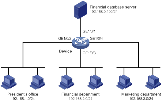
A company interconnects its departments through the device. Configure a packet filter to:
· Permit access from the President's office at any time to the financial database server.
· Permit access from the Financial department to the database server only during working hours (from 8:00 to 18:00) on working days.
· Deny access from any other department to the database server.
Figure 1 Network diagram
Configuration procedure
# Create a periodic time range from 8:00 to 18:00 on working days.
<Device> system-view
[Device] time-range work 08:0 to 18:00 working-day
# Create an IPv4 advanced ACL numbered 3000.
[Device] acl advanced 3000
# Configure a rule to permit access from the President's office to the financial database server.
[Device-acl-ipv4-adv-3000] rule permit ip source 192.168.1.0 0.0.0.255 destination 192.168.0.100 0
# Configure a rule to permit access from the Financial department to the database server during working hours.
[Device-acl-ipv4-adv-3000] rule permit ip source 192.168.2.0 0.0.0.255 destination 192.168.0.100 0 time-range work
# Configure a rule to deny access to the financial database server.
[Device-acl-ipv4-adv-3000] rule deny ip source any destination 192.168.0.100 0
[Device-acl-ipv4-adv-3000] quit
# Apply IPv4 advanced ACL 3000 to filter outgoing packets on interface GigabitEthernet 1/0/1.
[Device] interface gigabitethernet 1/0/1
[Device-GigabitEthernet1/0/1] packet-filter 3000 outbound
[Device-GigabitEthernet1/0/1] quit
Verifying the configuration
# Verify that a PC in the Financial department can ping the database server during working hours. (All PCs in this example use Windows XP).
C:\> ping 192.168.0.100
Pinging 192.168.0.100 with 32 bytes of data:
Reply from 192.168.0.100: bytes=32 time=1ms TTL=255
Reply from 192.168.0.100: bytes=32 time<1ms TTL=255
Reply from 192.168.0.100: bytes=32 time<1ms TTL=255
Reply from 192.168.0.100: bytes=32 time<1ms TTL=255
Ping statistics for 192.168.0.100:
Packets: Sent = 4, Received = 4, Lost = 0 (0% loss),
Approximate round trip times in milli-seconds:
Minimum = 0ms, Maximum = 1ms, Average = 0ms
# Verify that a PC in the Marketing department cannot ping the database server during working hours.
C:\> ping 192.168.0.100
Pinging 192.168.0.100 with 32 bytes of data:
Request timed out.
Request timed out.
Request timed out.
Request timed out.
Ping statistics for 192.168.0.100:
Packets: Sent = 4, Received = 0, Lost = 4 (100% loss),
# Display configuration and match statistics for IPv4 advanced ACL 3000 on the device during working hours.
[Device] display acl 3000
Advanced IPv4 ACL 3000, 3 rules,
ACL's step is 5
rule 0 permit ip source 192.168.1.0 0.0.0.255 destination 192.168.0.100 0
rule 5 permit ip source 192.168.2.0 0.0.0.255 destination 192.168.0.100 0 time-range work (4 times matched) (Active)
rule 10 deny ip destination 192.168.0.100 0 (4 times matched)
The output shows that rule 5 is active. Rule 5 and rule 10 have been matched four times as the result of the ping operations.
Zone pair-based packet filter configuration example
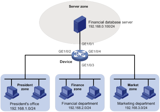
Network requirements
A company interconnects its departments through the device. The financial database server, President's office, Financial department, and Marketing department belong to different security zones. Configure a packet filter to:
· Permit access from the President's office at any time to the financial database server.
· Permit access from the Financial department to the financial database server only during working hours (from 8:00 to 18:00) on working days.
· Deny access from any other department to the financial database server.
Figure 2 Network diagram
Configuration procedure
# Create security zone Server, and add interface GigabitEthernet 1/0/1 to the security zone.
<Device> system-view
[Device] security-zone name Server
[Device-security-zone-Server] import interface gigabitethernet 1/0/1
[Device-security-zone-Server] quit
# Create security zone President, and add interface GigabitEthernet 1/0/2 to the security zone.
[Device] security-zone name President
[Device-security-zone-President] import interface gigabitethernet 1/0/2
[Device-security-zone-President] quit
# Create security zone Finance, and add interface GigabitEthernet 1/0/3 to the security zone.
[Device] security-zone name Finance
[Device-security-zone-Finance] import interface gigabitethernet 1/0/3
[Device-security-zone-Finance] quit
# Create security zone Market, and add interface GigabitEthernet 1/0/4 to the security zone.
[Device] security-zone name Market
[Device-security-zone-Market] import interface gigabitethernet 1/0/4
[Device-security-zone-Market] quit
# Create a periodic time range from 8:00 to 18:00 on working days.
[Device] time-range work 08:0 to 18:00 working-day
# Configure ACL 3000 to permit access from the President's office at any time to the financial database server.
[Device] acl advanced 3000
[Device-acl-ipv4-adv-3000] rule permit ip source 192.168.1.0 0.0.0.255 destination 192.168.0.100 0
[Device-acl-ipv4-adv-3000] quit
# Configure ACL 3001 to permit access from the Financial department to the financial database server only during working hours on working days.
[Device] acl advanced 3001
[Device-acl-ipv4-adv-3001] rule permit ip source 192.168.2.0 0.0.0.255 destination 192.168.0.100 0 time-range work
[Device-acl-ipv4-adv-3001] quit
# Configure ACL 3002 to deny access from any other department to the financial database server.
[Device] acl advanced 3002
[Device-acl-ipv4-adv-3002] rule deny ip source any destination 192.168.0.100 0
[Device-acl-ipv4-adv-3002] quit
# Create a zone pair with the source security zone President and destination security zone Server. Apply ACL 3000 to the zone pair for packet filtering.
[Device] zone-pair security source president destination server
[Device-zone-pair-security-President-Server] packet-filter 3000
[Device-zone-pair-security-President-Server] quit
# Create a zone pair with the source security zone Finance and destination security zone Server. Apply ACL 3001 to the zone pair for packet filtering.
[Device] zone-pair security source finance destination server
[Device-zone-pair-security-Finance-Server] packet-filter 3001
[Device-zone-pair-security-President-Server] quit
# Create a zone pair with the source security zone Market and destination security zone Server. Apply ACL 3002 to the zone pair for packet filtering.
[Device] zone-pair security source market destination server
[Device-zone-pair-security-Market-Server] packet-filter 3002
[Device-zone-pair-security-Market-Server] quit
Verifying the configuration
# Verify that a PC in the Financial department can ping the database server during working hours. (All PCs in this example use Windows XP).
C:\> ping 192.168.0.100
Pinging 192.168.0.100 with 32 bytes of data:
Reply from 192.168.0.100: bytes=32 time=1ms TTL=255
Reply from 192.168.0.100: bytes=32 time<1ms TTL=255
Reply from 192.168.0.100: bytes=32 time<1ms TTL=255
Reply from 192.168.0.100: bytes=32 time<1ms TTL=255
Ping statistics for 192.168.0.100:
Packets: Sent = 4, Received = 4, Lost = 0 (0% loss),
Approximate round trip times in milli-seconds:
Minimum = 0ms, Maximum = 1ms, Average = 0ms
# Verify that a PC in the Marketing department cannot ping the database server during working hours.
C:\> ping 192.168.0.100
Pinging 192.168.0.100 with 32 bytes of data:
Request timed out.
Request timed out.
Request timed out.
Request timed out.
Ping statistics for 192.168.0.100:
Packets: Sent = 4, Received = 0, Lost = 4 (100% loss),
# Display configuration and match statistics for IPv4 advanced ACL 3001 and 3002 on the device during working hours.
[Device] display acl 3001
Advanced IPv4 ACL 3001, 1 rule,
ACL's step is 5
rule 0 permit ip source 192.168.2.0 0.0.0.255 destination 192.168.0.100 0 time-range work (4 times matched) (Active)
[Device] display acl 3002
Advanced IPv4 ACL 3002, 1 rule,
ACL's step is 5
rule 0 deny ip destination 192.168.0.100 0 (4 times matched)
The output shows that the rule in ACL 3001 is active. ACL 3001 and ACL 3002 both have been matched four times as the result of the ping operations.
QoS overview
In data communications, Quality of Service (QoS) provides differentiated service guarantees for diversified traffic in terms of bandwidth, delay, jitter, and drop rate, all of which can affect QoS.
QoS manages network resources and prioritizes traffic to balance system resources.
The following section describes typical QoS service models and widely used QoS techniques.
QoS service models
This section describes several typical QoS service models.
Best-effort service model
The best-effort model is a single-service model. The best-effort model is not as reliable as other models and does not guarantee delay-free delivery.
The best-effort service model is the default model for the Internet and applies to most network applications. It uses the First In First Out (FIFO) queuing mechanism.
IntServ model
The integrated service (IntServ) model is a multiple-service model that can accommodate diverse QoS requirements. This service model provides the most granularly differentiated QoS by identifying and guaranteeing definite QoS for each data flow.
In the IntServ model, an application must request service from the network before it sends data. IntServ signals the service request with the RSVP. All nodes receiving the request reserve resources as requested and maintain state information for the application flow. For more information about RSVP, see MPLS Configuration Guide.
The IntServ model demands high storage and processing capabilities because it requires all nodes along the transmission path to maintain resource state information for each flow. This model is suitable for small-sized or edge networks. However, it is not suitable for large-sized networks, for example, the core layer of the Internet, where billions of flows are present.
DiffServ model
The differentiated service (DiffServ) model is a multiple-service model that can meet diverse QoS requirements. It is easy to implement and extend. DiffServ does not signal the network to reserve resources before sending data, as IntServ does.
QoS techniques overview
The QoS techniques include the following features:
· Traffic classification.
· Traffic policing.
· Traffic shaping.
· Rate limit.
· Congestion management.
· Congestion avoidance.
The following section briefly introduces these QoS techniques.
All QoS techniques in this document are based on the DiffServ model.
Deploying QoS in a network
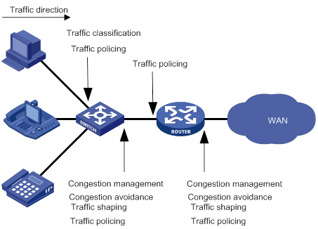
As shown in Figure 3, traffic classification, traffic shaping, traffic policing, congestion management, and congestion avoidance mainly implement the following functions:
· Traffic classification—Uses match criteria to assign packets with the same characteristics to a traffic class. Based on traffic classes, you can provide differentiated services.
· Traffic policing—Polices flows and imposes penalties to prevent aggressive use of network resources. You can apply traffic policing to both incoming and outgoing traffic of a port.
· Traffic shaping—Adapts the output rate of traffic to the network resources available on the downstream device to eliminate packet drops. Traffic shaping usually applies to the outgoing traffic of a port.
· Congestion management—Provides a resource scheduling policy to determine the packet forwarding sequence when congestion occurs. Congestion management usually applies to the outgoing traffic of a port.
· Congestion avoidance—Monitors the network resource usage. It is usually applied to the outgoing traffic of a port. When congestion worsens, congestion avoidance reduces the queue length by dropping packets.
Figure 3 Position of the QoS techniques in a network
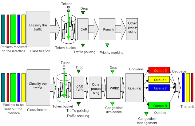
QoS processing flow in a device
Figure 4 briefly describes how the QoS module processes traffic.
1. Traffic classifier identifies and classifies traffic for subsequent QoS actions.
2. The QoS module takes various QoS actions on classified traffic as configured, depending on the traffic processing phase and network status. For example, you can configure the QoS module to perform the following operations:
? Traffic policing for incoming traffic.
? Traffic shaping for outgoing traffic.
? Congestion avoidance before congestion occurs.
? Congestion management when congestion occurs.
Command and hardware compatibility
Commands and descriptions for centralized devices apply to the following routers:
· MSR810/810-W/810-W-DB/810-LM/810-W-LM/810-10-PoE/810-LM-HK/810-W-LM-HK/810-LMS/810-LUS/810-LMS/810-LUS.
· MSR2600-6-X1/2600-10-X1.
· MSR 2630.
· MSR3600-28/3600-51.
· MSR3600-28-SI/3600-51-SI.
· MSR3610-X1/3610-X1-DP/3610-X1-DC/3610-X1-DP-DC.
· MSR 3610/3620/3620-DP/3640/3660.
· MSR810-LM-GL/810-W-LM-GL/830-6EI-GL/830-10EI-GL/830-6HI-GL/830-10HI-GL/2600-6-X1-GL/3600-28-SI-GL.
Commands and descriptions for distributed devices apply to the following routers:
· MSR5620.
· MSR 5660.
· MSR 5680.
Support for ATM interfaces depends on the device model. For more information, see the installation guide and the interface module manual.
PWs are not supported on the following routers:
· MSR810-LMS/810-LUS.
· MSR3600-28-SI/3600-51-SI.
IPv6-related parameters are not supported on the following routers:
· MSR810/810-W/810-W-DB/810-LM/810-W-LM/810-10-PoE/810-LM-HK/810-W-LM-HK/810-LMS/810-LUS.
· MSR3600-28-SI/3600-51-SI.
Configuring a QoS policy
You can configure QoS by using the MQC approach or non-MQC approach. Some features support both approaches, but some support only one.
Non-MQC approach
In the non-MQC approach, you configure QoS service parameters without using a QoS policy. For example, you can use the rate limit feature to set a rate limit on an interface without using a QoS policy.
MQC approach
In the modular QoS configuration (MQC) approach, you configure QoS service parameters by using QoS policies. A QoS policy defines the shaping, policing, or other QoS actions to take on different classes of traffic. It is a set of class-behavior associations.
A traffic class is a set of match criteria for identifying traffic, and it uses the AND or OR operator.
· If the operator is AND, a packet must match all the criteria to match the traffic class.
· If the operator is OR, a packet matches the traffic class if it matches any of the criteria in the traffic class.
A traffic behavior defines a set of QoS actions to take on packets, such as priority marking and redirect.
By associating a traffic behavior with a traffic class in a QoS policy, you apply QoS actions in the traffic behavior to the traffic class.
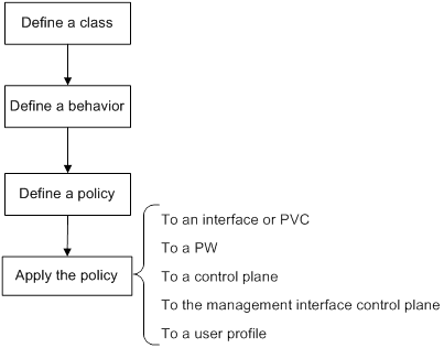
Configuration procedure diagram
Figure 5 shows how to configure a QoS policy.
Figure 5 QoS policy configuration procedure
Command and hardware compatibility
Support for ATM interfaces depends on the device model. For more information, see the installation guide and the interface module manual.
PWs are not supported on the following routers:
· MSR810-LMS/810-LUS.
· MSR3600-28-SI/3600-51-SI.
Defining a traffic class
|
Step |
Command |
Remarks |
|
1. Enter system view. |
system-view |
N/A |
|
2. Create a traffic class and enter traffic class view. |
traffic classifier classifier-name [ operator { and | or } ] |
By default, no traffic classes exist. |
|
3. Configure a match criterion. |
if-match [ not ] match-criteria |
By default, no match criterion is configured. For more information, see the if-match command in ACL and QoS Command Reference. |
Defining a traffic behavior
A traffic behavior is a set of QoS actions (such as traffic filtering, shaping, policing, and priority marking) to take on a traffic class.
To define a traffic behavior:
|
Step |
Command |
Remarks |
|
1. Enter system view. |
system-view |
N/A |
|
2. Create a traffic behavior and enter traffic behavior view. |
traffic behavior behavior-name |
By default, no traffic behaviors exist. |
|
3. Configure an action in the traffic behavior. |
See the subsequent chapters, depending on the purpose of the traffic behavior: traffic policing, traffic filtering, priority marking, traffic accounting, and so on. |
By default, no action is configured for a traffic behavior. |
Defining a QoS policy
Configuring a parent policy
To perform actions defined in a behavior for a class of packets, associate the behavior with the class in a QoS policy.
To associate a traffic class with a traffic behavior in a QoS policy:
|
Step |
Command |
Remarks |
|
1. Enter system view. |
system-view |
N/A |
|
2. Create a QoS policy and enter QoS policy view. |
qos policy policy-name |
By default, no QoS policies exist. |
|
3. Associate a traffic class with a traffic behavior to create a class-behavior association in the QoS policy. |
classifier classifier-name behavior behavior-name [ insert-before before-classifier-name ] |
By default, a traffic class is not associated with a traffic behavior. Repeat this step to create more class-behavior associations. |
Configuring a child policy
You can nest a QoS policy in a traffic behavior to reclassify the traffic class associated with the behavior. Then the system performs the actions defined in the QoS policy on the reclassified traffic. The QoS policy nested in the traffic behavior is called the child policy. The QoS policy that nests the behavior is called the parent policy.
To nest QoS policies successfully, follow these guidelines:
· If class-based queuing (CBQ) is configured in a child policy, make sure the following requirements are met:
? GTS is configured in the parent policy.
? The CIR specified in GTS is greater than or equal to CBQ bandwidth.
· If the CIR in GTS is specified as a percentage for a parent policy, configure the CBQ bandwidth as a percentage for the child policy.
· If the CIR in GTS is specified in kbps for a parent policy, configure the CBQ bandwidth as a percentage or in kbps for the child policy.
· GTS cannot be configured in the child policy.
To nest a child QoS policy in a parent QoS policy:
|
Step |
Command |
Remarks |
|
1. Enter system view. |
system-view |
N/A |
|
2. Create a traffic class for the parent policy and enter traffic class view. |
traffic classifier classifier-name [ operator { and | or } ] |
By default, no traffic classes exist. |
|
3. Configure a match criterion. |
if-match [ not ] match-criteria |
By default, no match criterion is configured. For more information about configuring match criteria, see ACL and QoS Command Reference. |
|
4. Return to system view. |
quit |
N/A |
|
5. Create a traffic behavior for the parent policy and enter traffic behavior view. |
traffic behavior behavior-name |
By default, no traffic behaviors exist. |
|
6. Nest the child QoS policy. |
traffic-policy policy-name |
By default, policy nesting is not configured. |
|
7. Return to system view. |
quit |
N/A |
|
8. Create the parent policy and enter parent policy view. |
qos policy policy-name |
By default, no parent policy exists. |
|
9. Associate the class with the behavior in the parent policy. |
classifier classifier-name behavior behavior-name |
By default, a class is not associated with a behavior. |
Applying the QoS policy
You can apply a QoS policy to the following destinations:
· Interface or PVC—The QoS policy takes effect on the traffic sent or received on the interface or PVC.
· PW—The QoS policy takes effect on the traffic of a PW. For information about PWs, see MPLS Configuration Guide.
· Control plane—The QoS policy takes effect on the traffic received on the control plane.
· Management interface control plane—The QoS policy takes effect on the traffic sent from the management interface to the control plane.
· User profile—The QoS policy takes effect on the traffic sent or received by the online users of the user profile.
You can modify traffic classes, traffic behaviors, and class-behavior associations in a QoS policy even after it is applied (except that it is applied to a user profile). If a traffic class uses an ACL for traffic classification, you can delete or modify the ACL.
Applying the QoS policy to an interface or PVC
A QoS policy can be applied to multiple interfaces or PVCs. However, only one QoS policy can be applied to one direction (inbound or outbound) of an interface or PVC.
The QoS policy applied to the outgoing traffic on an interface or PVC does not regulate local packets. Local packets refer to critical protocol packets sent by the local system for operation maintenance. The most common local packets include link maintenance, routing, LDP, RSVP, and SSH packets.
To apply a QoS policy to an interface or PVC:
|
Step |
Command |
Remarks |
|
1. Enter system view. |
system-view |
N/A |
|
2. Enter interface or PVC view. |
·
Enter interface view: a. interface atm interface-number b. pvc vpi/vci |
Settings in interface view take effect on the current interface. Settings in PVC view take effect on the current PVC. |
|
3. Apply the QoS policy to the interface or PVC. |
qos apply policy policy-name { inbound | outbound } |
By default, no QoS policy is applied to an interface or PVC. |
Applying the QoS policy to a PW
You can apply a QoS policy to one or more PWs only in the outbound direction.
To apply a QoS policy to a PW:
|
Step |
Command |
Remarks |
|
1. Enter system view. |
system-view |
N/A |
|
2. Enter PW view. |
· Enter cross-connect PW view: a. xconnect-group group-name b. connection connection-name · Enter VSI LDP PW view: e. pwsignaling ldp f. peer ip-address [ pw-id pw-id ] [ hub | no-split-horizon ] [ pw-class class-name | tunnel-policy tunnel-policy-name ] * · Enter VSI static PW view: g. vsi vsi-name [ hub-spoke ] h. pwsignaling static i. peer ip-address [ pw-id pw-id ] [ in-label label-value out-label label-value [ hub | no-split-horizon | pw-class class-name | tunnel-policy tunnel-policy-name ] * ] |
N/A |
|
3. Apply the QoS policy to the PW. |
qos apply policy policy-name outbound |
By default, no QoS policy is applied to a PW. |
Applying the QoS policy to a control plane
A device provides the data plane and the control plane.
· Data plane—The units at the data plane are responsible for receiving, transmitting, and switching (forwarding) packets, such as various dedicated forwarding chips. They deliver super processing speeds and throughput.
· Control plane—The units at the control plane are processing units running most routing and switching protocols. They are responsible for protocol packet resolution and calculation, such as CPUs. Compared with data plane units, the control plane units allow for great packet processing flexibility but have lower throughput.
When the data plane receives packets that it cannot recognize or process, it transmits them to the control plane. If the transmission rate exceeds the processing capability of the control plane, the control plane will be busy handling undesired packets. As a result, the control plane will fail to handle legitimate packets correctly or timely. As a result, protocol performance is affected.
To address this problem, apply a QoS policy to the control plane to take QoS actions, such as traffic filtering or rate limiting, on inbound traffic. This ensures that the control plane can correctly receive, transmit, and process packets.
Configuration restrictions and guidelines
When you apply a QoS policy to a control plane, follow these restrictions and guidelines:
· Some devices are enabled with predefined control plane QoS policies by default. A predefined control plane QoS policy uses the protocol type or protocol group type to identify the type of packets sent to the control plane. You can use protocol types or protocol group types in if-match commands in traffic class view for traffic classification. Then you can reconfigure traffic behaviors for these traffic classes as required. You can use the display qos policy control-plane pre-defined command to display predefined control plane QoS policies.
· If the hardware resources of an interface card are insufficient, applying a QoS policy to the control plane might fail on the interface card. The system does not automatically roll back the QoS policy configuration already applied to the MPU or other interface cards. To ensure consistency, you must use the undo qos apply policy command to manually remove the QoS policy configuration applied to them.
Configuration procedure
To apply the QoS policy to the control plane:
|
Step |
Command |
Remarks |
|
1. Enter system view. |
system-view |
N/A |
|
2. Enter control plane view. |
·
Centralized devices in standalone mode: ·
Distributed devices in standalone
mode/centralized devices in IRF mode: ·
Distributed devices in IRF mode: |
N/A |
|
3. Apply the QoS policy to the control plane. |
qos apply policy policy-name inbound |
By default, no QoS policy is applied to a control plane. |
Applying the QoS policy to the management interface control plane
The following matrix shows the feature and hardware compatibility:
|
Hardware |
Feature compatibility |
|
MSR810/810-W/810-W-DB/810-LM/810-W-LM/810-10-PoE/810-LM-HK/810-W-LM-HK/810-LMS/810-LUS |
No |
|
MSR2600-6-X1/2600-10-X1 |
No |
|
MSR 2630 |
No |
|
MSR3600-28/3600-51 |
No |
|
MSR3600-28-SI/3600-51-SI |
No |
|
MSR3610-X1/3610-X1-DP/3610-X1-DC/3610-X1-DP-DC |
No |
|
MSR 3610/3620/3620-DP/3640/3660 |
No |
|
MSR5620/5660/5680 |
Yes |
|
Hardware |
Feature compatibility |
|
MSR810-LM-GL |
Yes |
|
MSR810-W-LM-GL |
Yes |
|
MSR830-6EI-GL |
Yes |
|
MSR830-10EI-GL |
Yes |
|
MSR830-6HI-GL |
Yes |
|
MSR830-10HI-GL |
Yes |
|
MSR2600-6-X1-GL |
Yes |
|
MSR3600-28-SI-GL |
Yes |
If the rate of packets from the management interface to the control plane exceeds the processing capability, the control plane will fail to handle the packets correctly or timely. As a result, protocol performance is affected.
To address this problem, apply a rate-limiting QoS policy to the packets sent from the management interface to the control plane. This ensures that the control plane can correctly receive, transmit, and process packets from the management interface.
By default, the management interface is enabled with predefined rate-limiting QoS policies. To display the predefined QoS policies, use the display qos policy control-plane management pre-defined command. A predefined rate-limiting QoS policy uses the protocol type or protocol group type to identify the type of packets sent to the management interface. You can use protocol types or protocol group types in if-match commands in traffic class view for traffic classification. Then, you can reconfigure traffic behaviors for these traffic classes as required.
To apply the QoS policy to the management interface control plane:
|
Step |
Command |
Remarks |
|
1. Enter system view. |
system-view |
N/A |
|
2. Enter management interface control plane view. |
control-plane management |
N/A |
|
3. Apply the QoS policy to the management interface control plane. |
qos apply policy policy-name inbound |
By default, no QoS policy is applied to the management interface control plane. |
Applying the QoS policy to a user profile
The following matrix shows the feature and hardware compatibility:
|
Hardware |
Feature compatibility |
|
MSR810/810-W/810-W-DB/810-LM/810-W-LM/810-10-PoE/810-LM-HK/810-W-LM-HK |
Yes |
|
MSR810-LMS/810-LUS |
No |
|
MSR2600-6-X1/2600-10-X1 |
Yes |
|
MSR 2630 |
Yes |
|
MSR3600-28/3600-51 |
Yes |
|
MSR3600-28-SI/3600-51-SI |
Yes |
|
MSR3610-X1/3610-X1-DP/3610-X1-DC/3610-X1-DP-DC |
Yes |
|
MSR 3610/3620/3620-DP/3640/3660 |
Yes |
|
MSR5620/5660/5680 |
Yes |
|
Hardware |
Feature compatibility |
|
MSR810-LM-GL |
Yes |
|
MSR810-W-LM-GL |
Yes |
|
MSR830-6EI-GL |
Yes |
|
MSR830-10EI-GL |
Yes |
|
MSR830-6HI-GL |
Yes |
|
MSR830-10HI-GL |
Yes |
|
MSR2600-6-X1-GL |
Yes |
|
MSR3600-28-SI-GL |
Yes |
|
|
NOTE: The QoS policy applied to a user profile takes effect only when a user comes online through PPPoE authentication. |
You can apply a QoS policy to multiple user profiles. In one direction of each user profile, only one policy can be applied. To modify a QoS policy already applied to a direction, first remove the applied QoS policy.
To apply a QoS policy to a user profile:
|
Step |
Command |
Remarks |
|
1. Enter system view. |
system-view |
N/A |
|
2. Enter user profile view. |
user-profile profile-name |
The configuration made in user profile view takes effect only after it is successfully issued to the driver. |
|
3. Apply the QoS policy to the user profile. |
qos apply policy policy-name { inbound | outbound } |
By default, no QoS policy is applied to a user profile. Use the inbound keyword to apply the QoS policy to the incoming traffic of the device (traffic sent by the online users). Use the outbound keyword to apply the QoS policy to the outgoing traffic of the device (traffic received by the online users). |
Setting the QoS policy-based traffic rate statistics collection period for an interface
You can enable collection of per-class traffic statistics over a period of time, including the average forwarding rate and drop rate. For example, if you set the statistics collection period to n minutes, the system performs the following operations:
· Collects traffic statistics for the most recent n minutes.
· Refreshes the statistics every n/5 minutes.
You can use the display qos policy interface command to view the collected traffic rate statistics.
To set the QoS policy-based traffic rate statistics collection period for an interface:
|
Step |
Command |
Remarks |
|
1. Enter system view. |
system-view |
N/A |
|
2. Enter interface view. |
interface interface-type interface-number |
N/A |
|
3. Set the traffic rate statistics collection period for the interface. |
qos flow-interval interval |
The default setting is 5 minutes. A subinterface uses the statistics collection period configured on the main interface. A PVC uses the statistics collection period configured on the ATM main interface. |
Displaying and maintaining QoS policies
Execute display commands in any view and reset commands in user view.
|
Task |
Command |
|
Display traffic class configuration (centralized devices in standalone mode). |
display traffic classifier { system-defined | user-defined } [ classifier-name ] |
|
Display traffic class configuration (distributed devices in standalone mode/centralized devices in IRF mode). |
display traffic classifier { system-defined | user-defined } [ classifier-name ] [ slot slot-number ] |
|
Display traffic class configuration (distributed devices in IRF mode). |
display traffic classifier { system-defined | user-defined } [ classifier-name ] [ chassis chassis-number slot slot-number ] |
|
Display traffic behavior configuration (centralized devices in standalone mode). |
display traffic behavior { system-defined | user-defined } [ behavior-name ] |
|
Display traffic behavior configuration (distributed devices in standalone mode/centralized devices in IRF mode). |
display traffic behavior { system-defined | user-defined } [ behavior-name ] [ slot slot-number ] |
|
Display traffic behavior configuration (distributed devices in IRF mode). |
|
|
Display QoS policy configuration (centralized devices in standalone mode). |
display qos policy { system-defined | user-defined } [ policy-name [ classifier classifier-name ] ] |
|
Display QoS policy configuration (distributed devices in standalone mode/centralized devices in IRF mode). |
display qos policy { system-defined | user-defined } [ policy-name [ classifier classifier-name ] ] [ slot slot-number ] |
|
Display QoS policy configuration (distributed devices in IRF mode). |
display qos policy { system-defined | user-defined } [ policy-name [ classifier classifier-name ] ] [ chassis chassis-number slot slot-number ] |
|
Display QoS policies applied to hub-spoke tunnels on a tunnel interface. (For information about hub-spoke tunnels, see ADVPN in Layer 3—IP Services Configuration Guide.) |
display qos policy advpn tunnel number [ ipv4-address | ipv6-address ] [ outbound ] |
|
Display information about QoS policies applied to interfaces (centralized devices in standalone mode). |
display qos policy interface [ interface-type interface-number [ pvc { pvc-name | vpi/vci } ] ] [ inbound | outbound ] |
|
Display information about QoS policies applied to interfaces (distributed devices in standalone mode/centralized devices in IRF mode). |
display qos policy interface [ interface-type interface-number [ pvc { pvc-name | vpi/vci } ] ] [ slot slot-number ] [ inbound | outbound ] |
|
Display information about QoS policies applied to interfaces (distributed devices in IRF mode). |
display qos policy interface [ interface-type interface-number [ pvc { pvc-name | vpi/vci } ] ] [ chassis chassis-number slot slot-number ] [ inbound | outbound ] |
|
Display information about QoS policies applied to PWs. |
display qos policy l2vpn-pw [ peer ip-address pw-id pw-id ] [ outbound ] |
|
Display information about QoS policies applied to user profiles (centralized devices in standalone mode). |
display qos policy user-profile [ name profile-name ] [ user-id user-id ] [ inbound | outbound ] |
|
Display information about QoS policies applied to user profiles (distributed devices in standalone mode/centralized devices in IRF mode). |
display qos policy user-profile [ name profile-name ] [ user-id user-id ] [ slot slot-number ] [ inbound | outbound ] |
|
Display information about QoS policies applied to user profiles (distributed devices in IRF mode). |
display qos policy user-profile [ name profile-name ] [ user-id user-id ] [ chassis chassis-number slot slot-number ] [ inbound | outbound ] |
|
Display information about QoS policies applied to the control plane (centralized devices in standalone mode). |
display qos policy control-plane |
|
Display information about QoS policies applied to a control plane (distributed devices in standalone mode/centralized devices in IRF mode). |
display qos policy control-plane slot slot-number |
|
Display information about QoS policies applied to a control plane (distributed devices in IRF mode). |
display qos policy control-plane chassis chassis-number slot slot-number |
|
Display information about QoS policies applied to the management interface control plane. |
display qos policy control-plane management |
|
Display information about the predefined QoS policy applied to the control plane (centralized devices in standalone mode). |
display qos policy control-plane pre-defined |
|
Display information about the predefined QoS policy applied to the control plane (distributed devices in standalone mode/centralized devices in IRF mode). |
display qos policy control-plane pre-defined [ slot slot-number ] |
|
Display information about the predefined QoS policy applied to the control plane (distributed devices in IRF mode). |
display qos policy control-plane pre-defined [ chassis chassis-number slot slot-number ] |
|
Display information about the predefined QoS policy applied to the management interface control plane. |
display qos policy control-plane management pre-defined |
|
Clear the statistics for the QoS policy applied to the control plane (centralized devices in standalone mode). |
reset qos policy control-plane |
|
Clear the statistics for the QoS policy applied to a control plane (distributed devices in standalone mode/centralized devices in IRF mode). |
reset qos policy control-plane slot slot-number |
|
Clear the statistics for the QoS policy applied to a control plane (distributed devices in IRF mode). |
reset qos policy control-plane chassis chassis-number slot slot-number |
|
Clear the statistics for the QoS policy applied to the management interface control plane. |
reset qos policy control-plane management |
|
Clear the statistics for QoS policies applied to hub-spoke tunnels on a tunnel interface. (For information about hub-spoke tunnels, see ADVPN in Layer 3—IP Services Configuration Guide.) |
reset qos policy advpn tunnel number [ ipv4-address | ipv6-address ] [ outbound ] |
|
|
NOTE: Support for the display and reset commands depends on the device model. For more information, see ACL and QoS Command Reference. |
Configuring priority mapping
Overview
When a packet arrives, a device assigns a set of QoS priority parameters to the packet based on either of the following:
· A priority field carried in the packet.
· The port priority of the incoming port.
This process is called priority mapping. During this process, the device can modify the priority of the packet according to the priority mapping rules. The set of QoS priority parameters decides the scheduling priority and forwarding priority of the packet.
Priority mapping is implemented with priority maps and involves the following priorities:
· 802.1p priority.
· DSCP.
· EXP.
· IP precedence.
· Local precedence.
Introduction to priorities
Priorities include the following types: priorities carried in packets, and priorities locally assigned for scheduling only.
Packet-carried priorities include 802.1p priority, DSCP precedence, IP precedence, and EXP. These priorities have global significance and affect the forwarding priority of packets across the network. For more information about these priorities, see "Appendixes."
Locally assigned priorities only have local significance. They are assigned by the device only for scheduling. The locally assigned priorities are local precedence, which is used for queuing. A local precedence value corresponds to an output queue. A packet with higher local precedence is assigned to a higher priority output queue to be preferentially scheduled.
Priority maps
The device provides various types of priority maps. By looking through a priority map, the device decides which priority value to assign to a packet for subsequent packet processing.
The default priority maps (as shown in Appendix B Default priority maps) are available for priority mapping. They are adequate in most cases. If a default priority map cannot meet your requirements, you can modify the priority map as required.
Priority mapping configuration tasks
You can configure priority mapping by using any of the following methods:
· Configuring priority trust mode—In this method, you can configure a port to look up a trusted priority type (802.1p, for example) in incoming packets in the priority maps. Then, the system maps the trusted priority to the target priority types and values.
· Changing port priority—If no packet priority is trusted, the port priority of the incoming port is used. By changing the port priority of a port, you change the priority of the incoming packets on the port.
To configure priority mapping, perform the following tasks:
|
Tasks at a glance |
|
(Optional.) Configuring a priority map |
|
(Required.) Perform one of the following tasks: · Configuring a port to trust packet priority for priority mapping · Changing the port priority of an interface |
Configuring a priority map
By default, the device provides the following types of priority map:
|
Priority map |
Description |
|
dot1p-lp |
802.1p-local priority map. |
|
dscp-lp |
DSCP-local priority map. |
|
lp-dot1p |
Local-802.1p priority map. |
|
lp-dscp |
Local-DSCP priority map. |
To configure a priority map:
|
Step |
Command |
Remarks |
|
1. Enter system view. |
system-view |
N/A |
|
2. Enter priority map view. |
qos map-table { dot1p-lp | dscp-lp | lp-dot1p | lp-dscp } |
N/A |
|
3. Configure mappings for the priority map. |
import import-value-list export export-value |
By default, the default priority maps are used. For more information, see "Appendixes." If you execute this command multiple times, the most recent configuration takes effect. |
Configuring a port to trust packet priority for priority mapping
This feature is supported only on the following ports:
· Layer 2 Ethernet ports on Ethernet switching modules.
· Fixed Layer 2 Ethernet ports on MSR810/810-W/810-W-DB/810-LM/810-W-LM/810-10-PoE/810-LM-HK/810-W-LM-HK/810-LMS/810-LUS/MSR2600-6-X1/2600-10-X1/MSR3600-28/3600-51/3600-28-SI/3600-51-SI routers/MSR810-LM-GL/810-W-LM-GL/830-6EI-GL/830-10EI-GL/830-6HI-GL/830-10HI-GL/2600-6-X1-GL/3600-28-SI-GL.
You can configure the device to trust a particular priority field carried in packets for priority mapping on ports or globally.
When you configure the trusted packet priority type on an interface, use the following available keywords:
· dot1p—Uses the 802.1p priority of received packets for mapping.
· dscp—Uses the DSCP precedence of received IP packets for mapping.
To configure the trusted packet priority type on an interface:
|
Step |
Command |
Remarks |
|
1. Enter system view. |
system-view |
N/A |
|
2. Enter interface view. |
interface interface-type interface-number |
N/A |
|
3. Configure the trusted packet priority type. |
qos trust { dot1p | dscp } |
By default, no priority trust mode is configured for an interface. The dscp keyword is supported only on the following ports: · Layer 2 Ethernet ports on SIC-4GSW, SIC-4GSWP, SIC-4GSWF, HMIM-8GSWF HMIM-24GSW/24GSWP, and HMIM-8GSW modules. · Fixed Layer 2 Ethernet ports on MSR810/810-W/810-W-DB/810-LM/810-W-LM/810-10-PoE/810-LM-HK/810-W-LM-HK/810-LMS/810-LUS/MSR2600-6-X1/2600-10-X1/MSR3600-28/3600-51/3600-28-SI/3600-51-SI routers. |
Changing the port priority of an interface
This feature is supported only on the following ports:
· Layer 2 Ethernet ports on Ethernet switching modules.
· Fixed Layer 2 Ethernet ports on MSR810/810-W/810-W-DB/810-LM/810-W-LM/810-10-PoE/810-LM-HK/810-W-LM-HK/810-LMS/810-LUS/MSR2600-6-X1/2600-10-X1/MSR3600-28/3600-51/3600-28-SI/3600-51-SI routers/MSR810-LM-GL/810-W-LM-GL/830-6EI-GL/830-10EI-GL/830-6HI-GL/830-10HI-GL/2600-6-X1-GL/3600-28-SI-GL routers.
If an interface does not trust any packet priority, the device uses its port priority to look for priority parameters for the incoming packets. By changing port priority, you can prioritize traffic received on different interfaces.
To change the port priority of an interface:
|
Step |
Command |
Remarks |
|
1. Enter system view. |
system-view |
N/A |
|
2. Enter interface view. |
interface interface-type interface-number |
N/A |
|
3. Set the port priority of the interface. |
qos priority priority-value |
The default setting is 0. |
Displaying and maintaining priority mapping
Execute display commands in any view.
|
Task |
Command |
|
Display priority map configuration. |
display qos map-table [ dot1p-lp | dscp-lp | lp-dot1p | lp-dscp ] |
|
Display the trusted packet priority type on a port. |
display qos trust interface [ interface-type interface-number ] |
Priority mapping configuration examples
Priority trust mode configuration example
Network requirements
As shown in Figure 6:
· The 802.1p priority of traffic from Device A to Device C is 3.
· The 802.1p priority of traffic from Device B to Device C is 1.
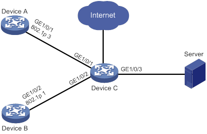
Configuration procedure
# Assign port priority to GigabitEthernet 1/0/1 and GigabitEthernet 1/0/2. Make sure the following requirements are met:
· The priority of GigabitEthernet 1/0/1 is higher than that of GigabitEthernet 1/0/2.
· No trusted packet priority type is configured on GigabitEthernet 1/0/1 or GigabitEthernet 1/0/2.
<DeviceC> system-view
[DeviceC] interface gigabitethernet 1/0/1
[DeviceC-GigabitEthernet1/0/1] qos priority 3
[DeviceC-GigabitEthernet1/0/1] quit
[DeviceC] interface gigabitethernet 1/0/2
[DeviceC-GigabitEthernet1/0/2] qos priority 1
[DeviceC-GigabitEthernet1/0/2] quit
Priority mapping table and priority marking configuration example
Network requirements
As shown in Figure 7:
· The Marketing department connects to GigabitEthernet 1/0/1 of Device, which sets the 802.1p priority of traffic from the Marketing department to 3.
· The R&D department connects to GigabitEthernet 1/0/2 of Device, which sets the 802.1p priority of traffic from the R&D department to 4.
· The Management department connects to GigabitEthernet 1/0/3 of Device, which sets the 802.1p priority of traffic from the Management department to 5.
Configure port priority, 802.1p-to-local mapping table, and priority marking to implement the plan as described in Table 2.
|
Traffic destination |
Traffic priority order |
Queuing plan |
||
|
Traffic source |
Output queue |
Queue priority |
||
|
Public servers |
R&D department > Management department > Marketing department |
R&D department |
6 |
High |
|
Management department |
4 |
Medium |
||
|
Marketing department |
2 |
Low |
||
|
Internet |
Management department > Marketing department > R&D department |
R&D department |
2 |
Low |
|
Management department |
6 |
High |
||
|
Marketing department |
3 |
Medium |
||
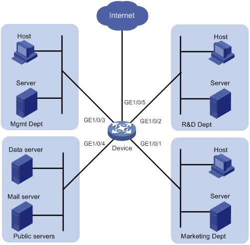
Configuration procedure
1. Configure trusting port priority:
# Set the port priority of GigabitEthernet 1/0/1 to 3.
<Device> system-view
[Device] interface gigabitethernet 1/0/1
[Device-GigabitEthernet1/0/1] qos priority 3
[Device-GigabitEthernet1/0/1] quit
# Set the port priority of GigabitEthernet 1/0/2 to 4.
[Device] interface gigabitethernet 1/0/2
[Device-GigabitEthernet1/0/2] qos priority 4
[Device-GigabitEthernet1/0/2] quit
# Set the port priority of GigabitEthernet 1/0/3 to 5.
[Device] interface gigabitethernet 1/0/3
[Device-GigabitEthernet1/0/3] qos priority 5
[Device-GigabitEthernet1/0/3] quit
2. Configure the 802.1p-to-local mapping table to map 802.1p priority values 3, 4, and 5 to local precedence values 2, 6, and 4.
This guarantees the R&D department, Management department, and Marketing department decreased priorities to access the public servers.
[Device] qos map-table dot1p-lp
[Device-maptbl-dot1p-lp] import 3 export 2
[Device-maptbl-dot1p-lp] import 4 export 6
[Device-maptbl-dot1p-lp] import 5 export 4
[Device-maptbl-dot1p-lp] quit
3. Map the local precedence values 6 and 2 to local precedence values 2 and 3 and keep local precedence value 4 unchanged.
This guarantees the Management department, Marketing department, and R&D department decreased priorities to access the Internet.
[Device] traffic classifier rd
[Device-classifier-rd] if-match local-precedence 6
[Device-classifier-rd] quit
[Device] traffic classifier market
[Device-classifier-market] if-match local-precedence 2
[Device-classifier-market] quit
[Device] traffic behavior rd
[Device-behavior-rd] remark local-precedence 2
[Device-behavior-rd] quit
[Device] traffic behavior market
[Device-behavior-market] remark local-precedence 3
[Device-behavior-market] quit
[Device] qos policy policy1
[Device-qospolicy-policy1] classifier rd behavior rd
[Device-qospolicy-policy1] classifier market behavior market
[Device-qospolicy-policy1] quit
[Device] interface gigabitethernet 1/0/5
[Device-GigabitEthernet1/0/5] qos apply policy policy1 outbound
Configuring traffic policing, GTS, and rate limit
Overview
Traffic policing helps assign network resources (including bandwidth) and increase network performance. For example, you can configure a flow to use only the resources committed to it in a certain time range. This avoids network congestion caused by burst traffic.
Traffic policing, Generic Traffic Shaping (GTS), and rate limit control the traffic rate and resource usage according to traffic specifications. You can use token buckets for evaluating traffic specifications.
Traffic evaluation and token buckets
Token bucket features
A token bucket is analogous to a container that holds a certain number of tokens. Each token represents a certain forwarding capacity. The system puts tokens into the bucket at a constant rate. When the token bucket is full, the extra tokens cause the token bucket to overflow.
Evaluating traffic with the token bucket
A token bucket mechanism evaluates traffic by looking at the number of tokens in the bucket. If the number of tokens in the bucket is enough for forwarding the packets:
· The traffic conforms to the specification (called conforming traffic).
· The corresponding tokens are taken away from the bucket.
Otherwise, the traffic does not conform to the specification (called excess traffic).
A token bucket has the following configurable parameters:
· Mean rate at which tokens are put into the bucket, which is the permitted average rate of traffic. It is usually set to the committed information rate (CIR).
· Burst size or the capacity of the token bucket. It is the maximum traffic size permitted in each burst. It is usually set to the committed burst size (CBS). The set burst size must be greater than the maximum packet size.
Each arriving packet is evaluated.
Complicated evaluation
You can set two token buckets, bucket C and bucket E, to evaluate traffic in a more complicated environment and achieve more policing flexibility. For example, traffic policing uses the following mechanisms:
· Single rate two color—Uses one token bucket and the following parameters:
? CIR—Rate at which tokens are put into bucket C. It sets the average packet transmission or forwarding rate allowed by bucket C.
? CBS—Size of bucket C, which specifies the transient burst of traffic that bucket C can forward.
When a packet arrives, the following rules apply:
? If bucket C has enough tokens to forward the packet, the packet is colored green.
? Otherwise, the packet is colored red.
· Single rate three color—Uses two token buckets and the following parameters:
? CIR—Rate at which tokens are put into bucket C. It sets the average packet transmission or forwarding rate allowed by bucket C.
? CBS—Size of bucket C, which specifies the transient burst of traffic that bucket C can forward.
? EBS—Size of bucket E minus size of bucket C, which specifies the transient burst of traffic that bucket E can forward. The EBS cannot be 0. The size of E bucket is the sum of the CBS and EBS.
When a packet arrives, the following rules apply:
? If bucket C has enough tokens, the packet is colored green.
? If bucket C does not have enough tokens but bucket E has enough tokens, the packet is colored yellow.
? If neither bucket C nor bucket E has sufficient tokens, the packet is colored red.
· Two rate three color—Uses two token buckets and the following parameters:
? CIR—Rate at which tokens are put into bucket C. It sets the average packet transmission or forwarding rate allowed by bucket C.
? CBS—Size of bucket C, which specifies the transient burst of traffic that bucket C can forward.
? PIR—Rate at which tokens are put into bucket E, which specifies the average packet transmission or forwarding rate allowed by bucket E.
? EBS—Size of bucket E, which specifies the transient burst of traffic that bucket E can forward.
When a packet arrives, the following rules apply:
? If bucket C has enough tokens, the packet is colored green.
? If bucket C does not have enough tokens but bucket E has enough tokens, the packet is colored yellow.
? If neither bucket C nor bucket E has sufficient tokens, the packet is colored red.
Traffic policing
Traffic policing supports policing the inbound traffic and the outbound traffic.
A typical application of traffic policing is to supervise the specification of traffic entering a network and limit it within a reasonable range. Another application is to "discipline" the extra traffic to prevent aggressive use of network resources by an application. For example, you can limit bandwidth for HTTP packets to less than 50% of the total. If the traffic of a session exceeds the limit, traffic policing can drop the packets or reset the IP precedence of the packets. Figure 8 shows an example of policing outbound traffic on an interface.
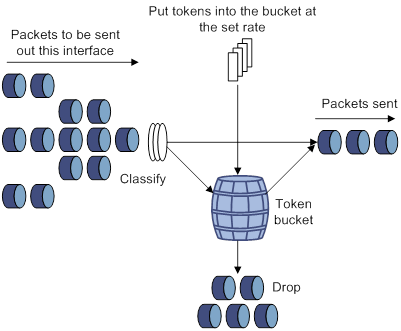
Traffic policing is widely used in policing traffic entering the ISP networks. It can classify the policed traffic and take predefined policing actions on each packet depending on the evaluation result:
· Forwarding the packet if the evaluation result is "conforming."
· Dropping the packet if the evaluation result is "excess."
· Forwarding the packet with its precedence re-marked if the evaluation result is "conforming."
· Delivering the packet to next-level traffic policing with its precedence re-marked if the evaluation result is "conforming."
GTS
GTS supports shaping the outbound traffic. GTS limits the outbound traffic rate by buffering exceeding traffic. You can use GTS to adapt the traffic output rate on a device to the input traffic rate of its connected device to avoid packet loss.
The differences between traffic policing and GTS are as follows:
· Packets to be dropped with traffic policing are retained in a buffer or queue with GTS, as shown in Figure 9. When enough tokens are in the token bucket, the buffered packets are sent at an even rate.
· GTS can result in additional delay and traffic policing does not.
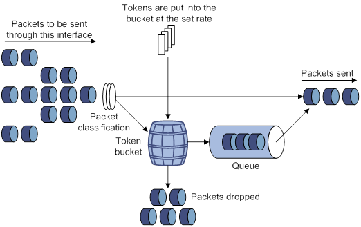
For example, in Figure 10, Router B performs traffic policing on packets from Router A and drops packets exceeding the limit. To avoid packet loss, you can perform GTS on the outgoing interface of Router A so that packets exceeding the limit are cached in Router A. Once resources are released, GTS takes out the cached packets and sends them out.
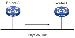
Rate limit
The rate limit of an interface or PW specifies the maximum rate for sending packets (excluding critical packets).
Rate limit also uses token buckets for traffic control. When rate limit is configured on an interface, a token bucket handles all packets to be sent through the interface for rate limiting. If enough tokens are in the token bucket, packets can be forwarded. Otherwise, packets are put into QoS queues for congestion management. In this way, the traffic passing the interface is controlled.
Figure 11 Rate limit implementation
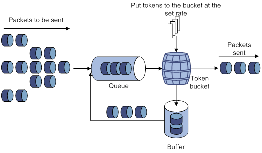
The token bucket mechanism limits traffic rate when accommodating bursts. It allows bursty traffic to be transmitted if enough tokens are available. If tokens are scarce, packets cannot be transmitted until efficient tokens are generated in the token bucket. It restricts the traffic rate to the rate for generating tokens.
Rate limit controls the total rate of all outgoing packets on an interface or PW. It is easier to use than traffic policing in controlling the total traffic rate.
Command and hardware compatibility
Commands and descriptions for centralized devices apply to the following routers:
· MSR810/810-W/810-W-DB/810-LM/810-W-LM/810-10-PoE/810-LM-HK/810-W-LM-HK/810-LMS/810-LUS.
· MSR2600-6-X1/2600-10-X1.
· MSR 2630.
· MSR3600-28/3600-51.
· MSR3600-28-SI/3600-51-SI.
· MSR3610-X1/3610-X1-DP/3610-X1-DC/3610-X1-DP-DC.
· MSR 3610/3620/3620-DP/3640/3660.
· MSR810-LM-GL/810-W-LM-GL/830-6EI-GL/830-10EI-GL/830-6HI-GL/830-10HI-GL/2600-6-X1-GL/3600-28-SI-GL
Commands and descriptions for distributed devices apply to the following routers:
· MSR5620.
· MSR 5660.
· MSR 5680.
Support for ATM interfaces depends on the device model. For more information, see the installation guide and the interface module manual.
PWs are not supported on the following routers:
· MSR810-LMS/810-LUS.
· MSR3600-28-SI/3600-51-SI.
Configuring traffic policing
You can configure traffic policing by using the MQC approach or the non-MQC approach. If both approaches are used, the MQC configuration takes effect.
Configuring traffic policing by using the MQC approach
|
Step |
Command |
Remarks |
|
1. Enter system view. |
system-view |
N/A |
|
2. Create a traffic class and enter traffic class view. |
traffic classifier classifier-name [ operator { and | or } ] |
By default, no traffic classes exist. |
|
3. Configure a match criterion. |
if-match [ not ] match-criteria |
By default, no match criterion is configured. For more information about the if-match command, see ACL and QoS Command Reference. |
|
4. Return to system view. |
quit |
N/A |
|
5. Create a traffic behavior and enter traffic behavior view. |
traffic behavior behavior-name |
By default, no traffic behaviors exist. |
|
6. Configure a traffic policing action. |
·
In absolute value: ·
In percentage: |
By default, no traffic policing action is configured. |
|
7. Return to system view. |
quit |
N/A |
|
8. Create a QoS policy and enter QoS policy view. |
qos policy policy-name |
By default, no QoS policies exist. |
|
9. Associate the traffic class with the traffic behavior in the QoS policy. |
classifier classifier-name behavior behavior-name |
By default, a traffic class is not associated with a traffic behavior. |
|
10. Return to system view. |
quit |
N/A |
|
11. Apply the QoS policy. |
· Applying the QoS policy to an interface or PVC · Applying the QoS policy to a control plane · Applying the QoS policy to the management interface control plane |
Choose one of the application destinations as needed. By default, no QoS policy is applied. |
Configuring traffic policing by using the non-MQC approach
Configuring CAR-list-based traffic policing
|
Step |
Command |
Remarks |
|
1. Enter system view. |
system-view |
N/A |
|
2. Configure a CAR list. |
qos carl carl-index { dscp dscp-list | mac mac-address | mpls-exp mpls-exp-value | precedence precedence-value | { destination-ip-address | source-ip-address } { range start-ip-address to end-ip-address | subnet ip-address mask-length } [ per-address [ shared-bandwidth ] ] } |
By default, no CAR lists exist. |
|
3. Enter interface view. |
interface interface-type interface-number |
N/A |
|
4. Apply a CAR-list-based CAR policy to the interface. |
qos car { inbound | outbound } carl carl-index cir committed-information-rate [ cbs committed-burst-size [ ebs excess-burst-size ] ] [ green action | red action | yellow action ] * qos car { inbound | outbound } carl carl-index cir committed-information-rate [ cbs committed-burst-size ] pir peak-information-rate [ ebs excess-burst-size ] [ green action | red action | yellow action ] * |
By default, no CAR policy is applied to an interface. |
Configuring ACL-based traffic policing
|
Step |
Command |
Remarks |
|
1. Enter system view. |
system-view |
N/A |
|
2. Enter interface view. |
interface interface-type interface-number |
N/A |
|
3. Configure an ACL-based CAR policy on the interface. |
qos car { inbound | outbound } acl [ ipv6 ] acl-number cir committed-information-rate [ cbs committed-burst-size [ ebs excess-burst-size ] ] [ green action | red action | yellow action ] * qos car { inbound | outbound } acl [ ipv6 ] acl-number cir committed-information-rate [ cbs committed-burst-size ] pir peak-information-rate [ ebs excess-burst-size ] [ green action | red action | yellow action ] * |
By default, no CAR policy is configured on an interface. |
Configuring traffic policing for all traffic
|
Step |
Command |
Remarks |
|
1. Enter system view. |
system-view |
N/A |
|
2. Enter interface view. |
interface interface-type interface-number |
N/A |
|
3. Configure a CAR policy for all traffic on the interface. |
qos car { inbound | outbound } any cir committed-information-rate [ cbs committed-burst-size [ ebs excess-burst-size ] ] [ green action | red action | yellow action ] * qos car { inbound | outbound } any cir committed-information-rate [ cbs committed-burst-size ] pir peak-information-rate [ ebs excess-burst-size ] [ green action | red action | yellow action ] * |
By default, no CAR policy is configured on an interface. |
Configuring traffic policing for a user profile
The following matrix shows the feature and hardware compatibility:
|
Hardware |
Feature compatibility |
|
MSR810/810-W/810-W-DB/810-LM/810-W-LM/810-10-PoE/810-LM-HK/810-W-LM-HK |
Yes |
|
MSR810-LMS/810-LUS |
No |
|
MSR2600-6-X1/2600-10-X1 |
Yes |
|
MSR 2630 |
Yes |
|
MSR3600-28/3600-51 |
Yes |
|
MSR3600-28-SI/3600-51-SI |
Yes |
|
MSR3610-X1/3610-X1-DP/3610-X1-DC/3610-X1-DP-DC |
Yes |
|
MSR 3610/3620/3620-DP/3640/3660 |
Yes |
|
MSR5620/5660/5680 |
Yes |
|
Hardware |
Feature compatibility |
|
MSR810-LM-GL |
Yes |
|
MSR810-W-LM-GL |
Yes |
|
MSR830-6EI-GL |
Yes |
|
MSR830-10EI-GL |
Yes |
|
MSR830-6HI-GL |
Yes |
|
MSR830-10HI-GL |
Yes |
|
MSR2600-6-X1-GL |
Yes |
|
MSR3600-28-SI-GL |
Yes |
|
|
NOTE: The CAR policy configured for a user profile takes effect only when a user comes online through PPPoE authentication. |
When a user profile is configured, you can perform traffic policing based on users. When any user of the user profile logs in, the authentication server automatically applies the CAR parameters configured for the user profile to the user. When the user logs off, the system automatically removes the CAR configuration without manual intervention.
To configure traffic policing for a user profile:
|
Step |
Command |
Remarks |
|
1. Enter system view. |
system-view |
N/A |
|
2. Enter user profile view. |
user-profile profile-name |
The configuration made in user profile view takes effect when the users are online. |
|
3. Configure a CAR policy for the user profile. |
qos car { inbound | outbound } any cir committed-information-rate [ cbs committed-burst-size [ ebs excess-burst-size ] ] qos car { inbound | outbound } any cir committed-information-rate [ cbs committed-burst-size ] pir peak-information-rate [ ebs excess-burst-size ] |
By default, no CAR policy is configured for a user profile. The conforming traffic is permitted to pass through, and the excess traffic is dropped. |
Configuring GTS
You can configure GTS by using either the MQC approach or non-MQC approach.
Configuring GTS by using the MQC approach
|
Step |
Command |
Remarks |
|
1. Enter system view. |
system-view |
N/A |
|
2. Create a traffic class and enter traffic class view. |
traffic classifier classifier-name [ operator { and | or } ] |
By default, no traffic classes exist. |
|
3. Configure a match criterion. |
if-match [ not ] match-criteria |
By default, no match criterion is configured. For configurable match criteria, see the if-match command in ACL and QoS Command Reference. |
|
4. Return to system view. |
quit |
N/A |
|
5. Create a traffic behavior and enter traffic behavior view. |
traffic behavior behavior-name |
By default, no traffic behaviors exist. |
|
6. Configure a GTS action. |
·
In absolute value: ·
In percentage: |
By default, no GTS action is configured. |
|
7. Return to system view. |
quit |
N/A |
|
8. Create a QoS policy and enter QoS policy view. |
qos policy policy-name |
By default, no QoS policies exist. |
|
9. Associate the class with the traffic behavior in the QoS policy. |
classifier classifier-name behavior behavior-name |
By default, a traffic class is not associated with a traffic behavior. |
|
10. Return to system view. |
quit |
N/A |
|
11. Apply the QoS policy. |
· Applying the QoS policy to an interface or PVC · Applying the QoS policy to a control plane |
By default, no QoS policy is applied. Choose one of the application destinations as needed. |
Configuring GTS by using the non-MQC approach
You can configure the following types of GTS when using the non-MQC approach:
· ACL-based GTS—Configures GTS parameters for traffic matching an ACL. By specifying multiple ACLs, you can set GTS parameters for traffic of different traffic classes.
· GTS for all traffic—Configures GTS parameters for all traffic.
Configuring ACL-based GTS
|
Step |
Command |
Remarks |
|
1. Enter system view. |
system-view |
N/A |
|
2. Enter interface view. |
interface interface-type interface-number |
N/A |
|
3. Configure ACL-based GTS on the interface. |
qos gts acl [ ipv6 ] acl-number cir committed-information-rate [ cbs committed-burst-size [ ebs excess-burst-size ] ] [ queue-length queue-length ] qos gts acl [ ipv6 ] acl-number cir committed-information-rate [ cbs committed-burst-size ] pir peak-information-rate [ ebs excess-burst-size ] [ queue-length queue-length ] |
By default, GTS is not configured on an interface. |
Configuring GTS for all traffic
|
Step |
Command |
Remarks |
|
1. Enter system view. |
system-view |
N/A |
|
2. Enter interface view. |
interface interface-type interface-number |
N/A |
|
3. Configure GTS on the interface. |
qos gts any cir committed-information-rate [ cbs committed-burst-size [ ebs excess-burst-size ] ] [ queue-length queue-length ] qos gts any cir committed-information-rate [ cbs committed-burst-size ] pir peak-information-rate [ ebs excess-burst-size ] [ queue-length queue-length ] |
By default, GTS is not configured on an interface. |
Configuring the rate limit
Configuring the rate limit for an interface
The rate limit for an interface specifies the maximum rate of outgoing packets on the interface.
To configure the rate limit for an interface:
|
Step |
Command |
Remarks |
|
1. Enter system view. |
system-view |
N/A |
|
2. Enter interface view. |
interface interface-type interface-number |
N/A |
|
3. Configure the rate limit for the interface. |
qos lr outbound cir committed-information-rate [ cbs committed-burst-size [ ebs excess-burst-size ] ] |
By default, no rate limit is configured on an interface. |
Configuring the rate limit for a PW
The rate limit for a PW specifies the maximum rate of outgoing packets on the PW.
To configure the rate limit for a PW:
|
Step |
Command |
Remarks |
|
1. Enter system view. |
system-view |
N/A |
|
2. Enter PW view. |
· Enter cross-connect PW view: a. xconnect-group group-name b. connection connection-name c. peer ip-address pw-id pw-id [ in-label label-value out-label label-value ] [ pw-class class-name | tunnel-policy tunnel-policy-name ] * · Enter VSI LDP PW view: d. vsi vsi-name [ hub-spoke ] e. pwsignaling ldp f. peer ip-address [ pw-id pw-id ] [ hub | no-split-horizon ] [ pw-class class-name | tunnel-policy tunnel-policy-name ] * · Enter VSI static PW view: g. vsi vsi-name [ hub-spoke ] h. pwsignaling static i. peer ip-address [ pw-id pw-id ] [ in-label label-value out-label label-value [ hub | no-split-horizon | pw-class class-name | tunnel-policy tunnel-policy-name ] * ] |
N/A |
|
3. Configure the rate limit for the PW. |
qos lr outbound cir committed-information-rate [ cbs committed-burst-size [ ebs excess-burst-size ] ] |
By default, no rate limit is configured for a PW. |
Displaying and maintaining traffic policing, GTS, and rate limit
Execute display commands in any view.
|
Task |
Command |
|
Display CAR configuration and statistics on an interface. |
display qos car interface [ interface-type interface-number ] |
|
Display CAR list information (centralized devices in standalone mode). |
display qos carl [ carl-index ] |
|
Display CAR list information (distributed devices in standalone mode/centralized devices in IRF mode). |
display qos carl [ carl-index ] [ slot slot-number ] |
|
Display CAR list information (distributed devices in IRF mode). |
display qos carl [ carl-index ] [ chassis chassis-number slot slot-number ] |
|
Display traffic behavior configuration. |
display traffic behavior user-defined [ behavior-name ] |
|
Display GTS configuration and statistics for interfaces. |
display qos gts interface [ interface-type interface-number ] |
|
Display rate limit configuration and statistics for interfaces or PWs. |
display qos lr { interface [ interface-type interface-number ] | l2vpn-pw [ peer ip-address pw-id pw-id ] } |
Traffic policing, GTS, and rate limit configuration examples
Traffic policing and GTS configuration example
Network requirements
As shown in Figure 12:
· The server, Host A, and Host B can access the Internet through Router A and Router B.
· The server, Host A, and GigabitEthernet 1/0/1 of Router A are in the same network segment.
· Host B and GigabitEthernet 1/0/2 of Router A are in the same network segment.
Perform traffic control for the packets GigabitEthernet 1/0/1 of Router A receives from the server and Host A using the following guidelines:
· Limit the rate of packets from the server to 54 kbps. When the traffic rate is below 54 kbps, the traffic is forwarded. When the traffic rate exceeds 54 kbps, the excess packets are marked with IP precedence 0 and then forwarded.
· Limit the rate of packets from Host A to 8 kbps. When the traffic rate is below 8 kbps, the traffic is forwarded. When the traffic rate exceeds 8 kbps, the excess packets are dropped.
Perform traffic control on GigabitEthernet 1/0/1 and GigabitEthernet 1/0/2 of Router B using the following guidelines:
· Limit the incoming traffic rate on GigabitEthernet 1/0/1 to 500 kbps, and the excess packets are dropped.
· Limit the outgoing traffic rate on GigabitEthernet 1/0/2 to 1000 kbps, and the excess packets are dropped.
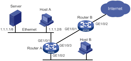
Configuration procedure
1. Configure Router A:
# Configure GTS on GigabitEthernet 1/0/3 to shape the packets when the sending rate exceeds 500 kbps. This decreases the packet loss rate of GigabitEthernet 1/0/1 of Router B.
<RouterA> system-view
[RouterA] interface gigabitethernet 1/0/3
[RouterA-GigabitEthernet1/0/3] qos gts any cir 500
[RouterA-GigabitEthernet1/0/3] quit
# Configure ACLs to permit the packets from the server and Host A.
[RouterA] acl basic 2001
[RouterA-acl-ipv4-basic-2001] rule permit source 1.1.1.1 0
[RouterA-acl-ipv4-basic-2001] quit
[RouterA] acl basic 2002
[RouterA-acl-ipv4-basic-2002] rule permit source 1.1.1.2 0
[RouterA-acl-ipv4-basic-2002] quit
# Configure CAR policies for different flows received on GigabitEthernet 1/0/1.
[RouterA] interface gigabitethernet 1/0/1
[RouterA-GigabitEthernet1/0/1] qos car inbound acl 2001 cir 54 cbs 4000 ebs 0 green pass red remark-prec-pass 0
[RouterA-GigabitEthernet1/0/1] qos car inbound acl 2002 cir 8 cbs 1875 ebs 0 green pass red discard
[RouterA-GigabitEthernet1/0/1] quit
2. Configure Router B:
# Configure a CAR policy on GigabitEthernet 1/0/1 to limit the incoming traffic rate to 500 kbps and drop the excess packets.
<RouterB> system-view
[RouterB] interface gigabitethernet 1/0/1
[RouterB-GigabitEthernet1/0/1] qos car inbound any cir 500 cbs 32000 ebs 0 green pass red discard
[RouterB-GigabitEthernet1/0/1] quit
# Configure a CAR policy on GigabitEthernet 1/0/2 to limit the sending rate to 1 Mbps and drop the excess packets.
[RouterB] interface gigabitethernet 1/0/2
[RouterB-GigabitEthernet1/0/2] qos car outbound any cir 1000 cbs 65000 ebs 0 green pass red discard
Per-IP-address traffic policing configuration example
Network requirements
As shown in Figure 13, configure a CAR-list-based CAR policy on GigabitEthernet 1/0/2 to meet the following requirements:
· Limit the rate of incoming packets from each IP address in the range of 2.1.1.1 to 2.1.1.100 to 5 kbps.
· Allow all IP addresses in the range to share the remaining bandwidth.
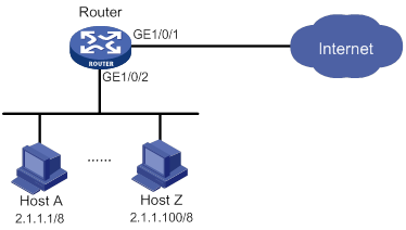
Configuration procedure
# Configure per-IP-address rate limiting on GigabitEthernet 1/0/2 to meet the following requirements:
· Limit the rate of each host on the network segment 2.1.1.1 through 2.1.1.100.
· Allow all IP addresses in the network segment to share the remaining bandwidth.
<Router> system-view
[Router] qos carl 1 source-ip-address range 2.1.1.1 to 2.1.1.100 per-address shared-bandwidth
[Router] interface gigabitethernet 1/0/2
[Router-GigabitEthernet1/0/2] qos car inbound carl 1 cir 500 cbs 1875 ebs 0 green pass red discard
[Router-GigabitEthernet1/0/2] quit
Configuring congestion management
Overview
Congestion occurs on a link or node when traffic size exceeds the processing capability of the link or node. It is typical of a statistical multiplexing network and can be caused by link failures, insufficient resources, and various other causes. Figure 14 shows common congestion scenarios.
Figure 14 Traffic congestion causes
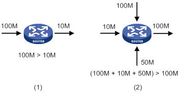
Congestion can introduce the following negative results:
· Increased delay and jitter during packet transmission.
· Decreased network throughput and resource use efficiency.
· Network resource (memory, in particular) exhaustion and system breakdown.
Congestion is unavoidable in switched networks or multiuser application environments. To improve the service performance of your network, implement congestion management policies.
For example, congestion management defines a resource dispatching policy to prioritize packets for forwarding when congestion occurs.
Congestion management involves queue creating, traffic classification, packet enqueuing, and queue scheduling.
Queuing is a common congestion management technique. It classifies traffic into queues and picks out packets from each queue by using an algorithm. Various queuing algorithms are available, and each addresses a particular network traffic problem. Your choice of algorithm significantly affects bandwidth assignment, delay, and jitter.
This section describes several common queue-scheduling mechanisms.
FIFO
As shown in Figure 15, the first in first out (FIFO) uses a single queue and does not classify traffic or schedule queues. FIFO delivers packets in their arrival order. The packet that arrives earlier is scheduled first. The only concern of FIFO is queue length, which affects delay and packet loss rate. On a device, resources are assigned to packets depending on their arrival order and load status of the device. The best-effort service model uses FIFO queuing.
FIFO does not address congestion problems. If only one FIFO output/input queue exists on a port, you cannot ensure timely delivery of mission-critical or delay-sensitive traffic or smooth traffic jitter. If malicious traffic occupies bandwidth aggressively, the problems increase. To control congestion and prioritize forwarding of critical traffic, use other queue scheduling mechanisms, where multiple queues can be configured. Within each queue, FIFO is still used.
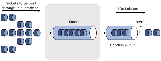
PQ
PQ is designed for mission-critical applications. Mission-critical applications require preferential treatment to reduce the response delay when congestion occurs. PQ can flexibly determine the order of forwarding packets by network protocol (for example, IP and IPX), incoming interface, packet length, source/destination address, and so on. Priority queuing classifies packets into four queues (top, middle, normal, and bottom queues, in descending priority order). By default, packets are assigned to the normal queue. Each of the four queues is a FIFO queue.
As shown in Figure 16, PQ schedules the four queues in descending order of priority. It sends packets in the queue with the highest priority first. When the queue with the highest priority is empty, it sends packets in the queue with the second highest priority. To make sure mission-critical packets are always served first, assign the mission-critical packets to the highest-priority queue. The common service packets that are assigned to the low-priority queues are transmitted when the high-priority queues are empty.
However, packets in the lower-priority queues cannot be transmitted when congestion occurs if packets exist in the higher-priority queues for a long time.
Figure 16 Priority queuing (PQ)
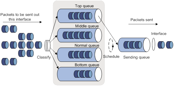
CQ
CQ provides 17 queues, numbered from 0 to 16. Queue 0 is a system queue, and queues 1 through 16 are user queues, as shown in Figure 17. You can define traffic classification rules and divide bandwidth across user queues by specifying the byte count for each queue. By default, packets are assigned to queue 1.
During a cycle of queue scheduling, CQ first empties the system queue. Then, it schedules the 16 queues in a round robin way. It sends a certain number of bytes out of each queue in the ascending order of queue 1 to queue 16. CQ guarantees a certain amount of bandwidth to common packets, and ensures that mission-critical packets are assigned more bandwidth. The bandwidth ratio for each queue is the byte count configured for that queue divided by the total byte count configured for all queues.
CQ can assign free bandwidth of idle queues to busy queues. Even though it performs round robin queue scheduling, CQ does not assign fixed time slots to the queues. If a queue is empty, CQ immediately moves to the next queue. When a class does not have packets, the bandwidth for other classes increases.
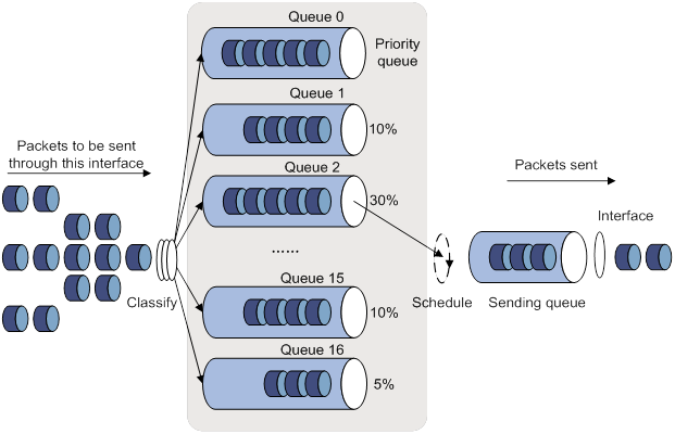
WFQ
FQ is designed to equally allocate network resources to reduce the delay and jitter of each traffic flow as much as possible. FQ follows these principles:
· Different queues have fair dispatching opportunities for delay balancing among flows.
· Short packets and long packets are equally scheduled. If long packets and short packets exist in queues, statistically the short packets are scheduled preferentially to reduce the jitter between packets.
WFQ considers weights when determining the queue scheduling order. Statistically, WFQ gives high-priority traffic more scheduling opportunities than low-priority traffic. To balance the delay of every traffic flow, WFQ performs the following operations:
· Automatically classifies traffic according to the "session" information of traffic.
· Attempts to provide as many queues as possible for traffic flows.
The session information of traffic includes the following information:
· Protocol type.
· TCP or UDP source/destination port numbers.
· Source/destination IP addresses.
· IP precedence bits in the ToS field.
When dequeuing packets, WFQ assigns the outgoing interface bandwidth to each traffic flow by precedence. The higher precedence value a traffic flow has, the more bandwidth it gets.
For example, five flows exist in the current interface with precedence 0, 1, 2, 3, and 4, respectively. The total bandwidth quota is the sum of all the (precedence value + 1)s, 1 + 2 + 3 + 4 + 5 = 15.
The bandwidth percentage assigned to each flow is (precedence value of the flow + 1)/total bandwidth quota. The bandwidth percentages for flows are 1/15, 2/15, 3/15, 4/15, and 5/15, respectively.
Because WFQ can balance the delay and jitter of each flow when congestion occurs, it is suitable for handling special situations. For example, WFQ is used in the assured forwarding (AF) services of the RSVP, and WFQ is used to schedule buffered packets in GTS.
Figure 18 Weighted fair queuing (WFQ)
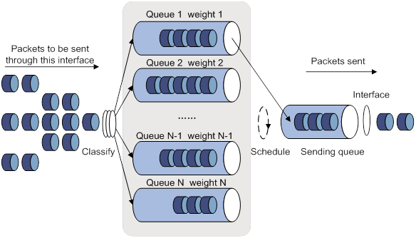
CBQ
Class-based queuing (CBQ) extends WFQ by supporting user-defined classes. When network congestion occurs, CBQ uses user-defined traffic match criteria to enqueue packets. Before packets are enqueued, congestion avoidance actions, such as tail drop or WRED and bandwidth restriction check, are performed. When being dequeued, packets are scheduled by WFQ.
CBQ provides the following queues:
· Emergency queue—Enqueues emergent packets. The emergency queue is a FIFO queue without bandwidth restriction.
· Strict priority (SP) queuing—SP queuing is designed for mission-critical applications. Mission-critical applications require preferential treatment to reduce the response delay when congestion occurs. With SP queuing, CBQ can provide strict priority service. A maximum of 64 SP queues are supported.
· Low Latency Queuing (LLQ)—An EF queue. Because packets are fairly treated in CBQ, delay-sensitive flows like video and voice packets might not be transmitted timely. To solve this problem, LLQ combines PQ and CBQ to preferentially transmit delay-sensitive flows like voice packets. When defining traffic classes for LLQ, you can configure a class of packets to be preferentially transmitted. The packets of all priority classes are assigned to the same priority queue. Bandwidth restriction on each class of packets is checked before the packets are enqueued. During the dequeuing operation, packets in the priority queue are transmitted first. To reduce the delay of the other queues except the priority queue, LLQ assigns the maximum available bandwidth to each priority class. The bandwidth value polices traffic during congestion. When no congestion is present, a priority class can use more than the bandwidth assigned to it. During congestion, the packets of each priority class exceeding the assigned bandwidth are discarded.
· Bandwidth queuing (BQ)—An AF queue. The BQ provides guaranteed bandwidth for AF traffic, and schedules the AF classes proportionally. The system supports up to 64 AF queues.
· Default queue—A WFQ queue. The default queue transmits the BE traffic by using the remaining interface bandwidth.
The system matches packets with classification rules in the following order:
· Match packets with priority classes and then the other classes.
· Match packets with priority classes in the configuration order.
· Match packets with other classes in the configuration order.
· Match packets with classification rules in a class in the configuration order.
Figure 19 CBQ
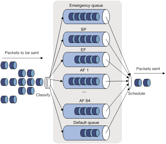
RTPQ
RTP queuing (RTPQ) is designed for delay-sensitive, real-time traffic (such as voice and video). You can assign voice or video packets to a high-priority queue by specifying a UDP port range as the match criterion. These packets are given strict priority service and are sent before packets in other queues are sent.
RTPQ can be used with FIFO, PQ, CQ, or WFQ, but not CBQ. CBQ can use LLQ to provide priority service for real-time traffic.
Figure 20 RTPQ
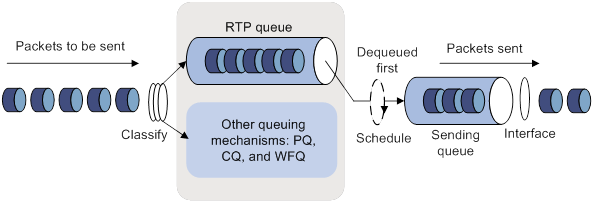
Congestion management technique comparison
Congestion management techniques offer different QoS capabilities to meet different application requirements, as explained in Table 3.
Table 3 Congestion management technique comparison
|
Type |
Number of queues |
Advantages |
Disadvantages |
|
FIFO |
1 |
· No need to configure, easy to use. · Easy to operate, low delay. |
· All packets are treated equally. The available bandwidth, delay and drop probability are determined by the arrival order of packets. · No restriction on traffic from connectionless protocols (protocols without any flow control mechanism, UDP, for example). This problem results in bandwidth loss for traffic of connection-oriented protocols (TCP, for example). · No delay guarantee for time-sensitive real-time applications, such as VoIP. |
|
PQ |
4 |
Provides strict priority service for mission-critical applications and guarantees low delay for real-time traffic, such as voice traffic. |
· Need to configure, low processing speed. · If packets always exist in high-priority queues, packets in low-priority queues cannot be sent. |
|
CQ |
16 |
· Bandwidth assignment in percentages for different applications. · Bandwidth reassignment to increase bandwidth for each class when packets of certain classes are not present. |
Need to configure, low processing speed. |
|
WFQ |
Configurable |
· Easy to configure. · Bandwidth guarantee for packets from cooperative (interactive) sources (such as TCP packets). · Reduces jitter. · Reduces the delay for interactive applications with a small amount of data. · Bandwidth assignment based on traffic priority. · Automatic bandwidth reassignment to increase bandwidth for each class when the number of traffic classes decreases. |
The processing speed is slower than FIFO. |
|
CBQ |
Configurable (0 to 64) |
· Flexible traffic classification based on rules and differentiated queue scheduling mechanisms for EF, AF and BE services. · Highly precise bandwidth guarantee and queue scheduling on the basis of AF service weights for various AF services. · Absolute preferential queue scheduling for the EF service to meet the delay requirement of real-time data. · Overcomes the PQ disadvantage where some low-priority queues are not serviced by restricting the high-priority traffic. · WFQ scheduling for best-effort traffic (the default class). |
The system overheads are large. |
|
RTPQ |
1 |
· Provides preferential treatment for real-time applications. · Performs traffic policing before enqueuing packets to prevent other queues from being starved. |
Applicable only to delay-sensitive applications, such as voice and video. |
Command and hardware compatibility
Commands and descriptions for centralized devices apply to the following routers:
· MSR810/810-W/810-W-DB/810-LM/810-W-LM/810-10-PoE/810-LM-HK/810-W-LM-HK/810-LMS/810-LUS.
· MSR2600-6-X1/2600-10-X1.
· MSR 2630.
· MSR3600-28/3600-51.
· MSR3600-28-SI/3600-51-SI.
· MSR3610-X1/3610-X1-DP/3610-X1-DC/3610-X1-DP-DC.
· MSR 3610/3620/3620-DP/3640/3660.
· MSR810-LM-GL/810-W-LM-GL/830-6EI-GL/830-10EI-GL/830-6HI-GL/830-10HI-GL/2600-6-X1-GL/3600-28-SI-GL.
Commands and descriptions for distributed devices apply to the following routers:
· MSR5620.
· MSR 5660.
· MSR 5680.
Support for ATM interfaces depends on the device model. For more information, see the installation guide and the interface module manual.
PWs are not supported on the following routers:
· MSR810-LMS/810-LUS.
· MSR3600-28-SI/3600-51-SI.
Setting the FIFO queue size
For the queuing feature to take effect on a subinterface, you must configure the rate limit on the subinterface.
Setting the FIFO queue size for an interface or PVC
|
Step |
Command |
Remarks |
|
1. Enter system view. |
system-view |
N/A |
|
2. Enter interface or PVC view. |
·
Enter interface view: · Enter PVC view: a. interface atm interface-number b. pvc vpi/vci |
N/A |
|
3. Set the FIFO queue size for the interface or PVC. |
qos fifo queue-length queue-length |
The default setting is 75. If the burst traffic is too heavy, increase the queue length to make queue scheduling more accurate. |
Setting the FIFO queue size for a PW
|
Step |
Command |
Remarks |
|
1. Enter system view. |
system-view |
N/A |
|
2. Enter PW view. |
· Enter cross-connect PW view: a. xconnect-group group-name b. connection connection-name c. peer ip-address pw-id pw-id [ in-label label-value out-label label-value ] [ pw-class class-name | tunnel-policy tunnel-policy-name ] * · Enter VSI LDP PW view: d. vsi vsi-name [ hub-spoke ] e. pwsignaling ldp f. peer ip-address [ pw-id pw-id ] [ hub | no-split-horizon ] [ pw-class class-name | tunnel-policy tunnel-policy-name ] * · Enter VSI static PW view: g. vsi vsi-name [ hub-spoke ] h. pwsignaling static i. peer ip-address [ pw-id pw-id ] [ in-label label-value out-label label-value [ hub | no-split-horizon | pw-class class-name | tunnel-policy tunnel-policy-name ] * ] |
N/A |
|
3. Set the FIFO queue size for the PW. |
qos fifo queue-length queue-length |
The default setting is 75. If the burst traffic is too heavy, increase the queue length to make queue scheduling more accurate. |
Configuring PQ
You can define a set of assignment rules in a PQ list and then apply the PQ list to an interface or PVC. An assignment rule assigns a packet that meets a specific match criterion to a queue.
When a packet arrives, it is examined against match criteria in their configuration order.
· When a match is found, the packet is assigned to the corresponding queue, and the matching process ends.
· If no match is found, the packet is assigned to the default queue.
Configuration restrictions and guidelines
· If you apply multiple PQ lists to an interface or PVC, the PQ list last applied takes effect.
· You must configure the rate limit for the queuing feature to take effect on the following interfaces:
? Tunnel interfaces.
? Subinterfaces.
? Layer 3 aggregate interfaces.
? HDLC link bundle interfaces.
? VT and dialer interfaces configured with PPPoE, PPPoA, PPPoEoA, PPPoFR, or MPoFR.
Configuration procedure
To configure PQ:
|
Step |
Command |
Remarks |
|
1. Enter system view. |
system-view |
N/A |
|
2. Configure a PQ list. |
· qos pql pql-index protocol { ip | ipv6 } [ queue-key key-value ] queue { bottom | middle | normal | top } · qos pql pql-index inbound-interface interface-type interface-number queue { bottom | middle | normal | top } · qos pql pql-index local-precedence local-precedence-list queue { bottom | middle | normal | top } · qos pql pql-index protocol mpls exp exp-list queue { bottom | middle | normal | top } |
Use one or more of the commands. |
|
3. (Optional.) Configure a queue as the default queue for a PQ list. |
qos pql pql-index default-queue { bottom | middle | normal | top } |
By default, the normal queue is the default queue. The default queue enqueues packets that do not match any criteria in a PQ list. |
|
4. (Optional.) Set the maximum queue length for a queue in a PQ list. |
qos pql pql-index queue { bottom | middle | normal | top } queue-length queue-length |
By default: · The maximum top queue length is 20. · The maximum middle queue length is 40. · The maximum normal queue length is 60. · The maximum bottom queue length is 80. In response to bursts of traffic, you can increase the maximum queue length to improve queue scheduling performance. |
|
5. Enter interface or PVC view. |
·
Enter interface view: · Enter PVC view: a. interface atm interface-number b. pvc vpi/vci |
N/A |
|
6. Apply a PQ list to the interface or PVC. |
qos pq pql pql-index |
By default, FIFO is used. |
|
7. (Optional.) Display the PQ configuration and statistics for interfaces or PVCs. |
display qos queue pq interface [ interface-type interface-number [ pvc { pvc-name | vpi/vci } ] ] |
If you specify a VT interface, this command displays the PQ configuration and statistics for all VA interfaces of the VT interface. A VT interface itself does not have QoS information. |
PQ configuration example
Network requirements
As shown in Figure 21, both the server and Host A send data to Host B through Router A. The server sends critical packets, and Host A sends non-critical packets.
Configure PQ on GigabitEthernet 1/0/2 of Router A, so that the critical packets from the server are transmitted preferentially when congestion occurs.
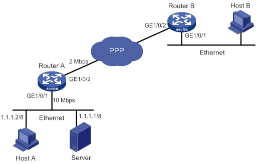
Configuration procedure
# Configure two ACLs to match packets from the server and Host A.
[RouterA] acl basic 2001
[RouterA-acl-ipv4-basic-2001] rule permit source 1.1.1.1 0
[RouterA] acl basic 2002
[RouterA-acl-ipv4-basic-2002] rule permit source 1.1.1.2 0
# Configure a PQ list to assign the packets from the server to the top queue when congestion occurs.
[RouterA] qos pql 1 protocol ip acl 2001 queue top
# Configure a PQ list to assign the packets from Host A to the bottom queue when congestion occurs.
[RouterA] qos pql 1 protocol ip acl 2002 queue bottom
# Set the maximum queue size of the top queue to 50 and that of the bottom queue to 100 in the PQ list.
[RouterA] qos pql 1 queue top queue-length 50
[RouterA] qos pql 1 queue bottom queue-length 100
# Apply PQ list 1 to GigabitEthernet 1/0/2.
[RouterA] interface gigabitethernet 1/0/2
[RouterA-GigabitEthernet1/0/2] qos pq pql 1
Configuring CQ
You can configure a CQ list that contains up to 16 queues. The CQ list specifies the following information:
· The queue where a packet is placed in.
· The maximum length of each queue.
· The number of bytes sent from the queue during a cycle of round robin scheduling.
Configuration restrictions and guidelines
· If you apply multiple CQ lists to an interface or PVC, the CQ list last applied takes effect.
· You must configure the rate limit for the CQ feature to take effect on the following interfaces:
? Tunnel interfaces.
? Subinterfaces.
? Layer 3 aggregate interfaces.
? HDLC link bundle interfaces.
? VT and dialer interfaces configured with PPPoE, PPPoA, PPPoEoA, PPPoFR, or MPoFR.
Configuration procedure
To configure CQ:
|
Step |
Command |
Remarks |
|
1. Enter system view. |
system-view |
N/A |
|
2. Configure a CQ list. |
· qos cql cql-index protocol { ip | ipv6 } [ queue-key key-value ] queue queue-id · qos cql cql-index inbound-interface interface-type interface-number queue queue-id · qos cql cql-index local-precedence local-precedence-list queue queue-id · qos cql cql-index protocol mpls exp exp-list queue queue-id |
Use one or more of the commands. |
|
3. (Optional.) Configure a queue as the default queue for a CQ list. |
qos cql cql-index default-queue queue-id |
By default, queue 1 is the default queue. The default queue enqueues packets that do not match any criteria in a CQ list. |
|
4. (Optional.) Set the maximum length of a queue in a CQ list. |
qos cql cql-index queue queue-id queue-length queue-length |
The default setting is 20. In response to bursts of traffic, you can increase the maximum queue length to improve queue scheduling performance. |
|
5. (Optional.) Configure the number of bytes sent from a queue during a cycle of round robin scheduling in a CQ list. |
qos cql cql-index queue queue-id serving byte-count |
The default setting is 1500 bytes. |
|
6. Enter interface view or PVC view. |
·
Enter interface view: · Enter PVC view: a. interface atm interface-number b. pvc vpi/vci |
N/A |
|
7. Apply a CQ list to the interface or PVC. |
qos cq cql cql-index |
By default, FIFO is used. |
|
8. (Optional.) Display the CQ configuration and statistics for interfaces or PVCs. |
display qos queue cq interface [ interface-type interface-number [ pvc { pvc-name | vpi/vci } ] ] |
If you specify a VT interface, this command displays the CQ configuration and statistics for all VA interfaces of the VT interface. A VT interface itself does not have QoS information. |
Configuring WFQ
Configuring WFQ for an interface or PVC
You must configure the rate limit for the WFQ feature to take effect on the following interfaces:
· Tunnel interfaces.
· Subinterfaces.
· Layer 3 aggregate interfaces.
· HDLC link bundle interfaces.
· VT and dialer interfaces configured with PPPoE, PPPoA, PPPoEoA, PPPoFR, or MPoFR.
On an interface or PVC that is not enabled with WFQ, the qos wfq command can enable WFQ and configure WFQ-related parameters. If WFQ has been enabled for the interface or PVC, the qos wfq command can modify the WFQ-related parameters.
To configure WFQ for an interface or PVC:
|
Step |
Command |
Remarks |
|
1. Enter system view. |
system-view |
N/A |
|
2. Enter interface or PVC view. |
·
Enter interface view: · Enter PVC view: a. interface atm interface-number b. pvc vpi/vci |
N/A |
|
3. Configure WFQ for the interface or PVC. |
qos wfq [ dscp | precedence ] [ queue-length max-queue-length | queue-number total-queue-number ] * |
By default, WFQ is not configured for an interface or PVC. |
Configuring WFQ for a PW
|
Step |
Command |
Remarks |
|
1. Enter system view. |
system-view |
N/A |
|
2. Enter PW view. |
· Enter cross-connect PW view: a. xconnect-group group-name b. connection connection-name c. peer ip-address pw-id pw-id [ in-label label-value out-label label-value ] [ pw-class class-name | tunnel-policy tunnel-policy-name ] * · Enter VSI LDP PW view: d. vsi vsi-name [ hub-spoke ] e. pwsignaling ldp f. peer ip-address [ pw-id pw-id ] [ hub | no-split-horizon ] [ pw-class class-name | tunnel-policy tunnel-policy-name ] * · Enter VSI static PW view: g. vsi vsi-name [ hub-spoke ] h. pwsignaling static i. peer ip-address [ pw-id pw-id ] [ in-label label-value out-label label-value [ hub | no-split-horizon | pw-class class-name | tunnel-policy tunnel-policy-name ] * ] |
N/A |
|
3. Configure WFQ for the PW. |
qos wfq [ dscp | precedence ] [ queue-length max-queue-length | queue-number total-queue-number ] * |
By default, WFQ is not configured for a PW. |
Configuring CBQ
Predefined classes, traffic behaviors, and policies
The system predefines the following classes, traffic behaviors, and policies:
Predefined classes
The system predefines some classes and defines general rules for the classes. You can use the following predefined classes when defining a policy:
· default-class—Matches the default traffic.
· ef, af1, af2, af3, af4—Matches IP DSCP value ef, af1, af2, af3, af4, respectively.
· ip-prec0, ip-prec1, …ip-prec7—Matches IP precedence value 0, 1, …7, respectively.
· mpls-exp0, mpls-exp1, …mpls-exp7—Matches MPLS EXP value 0, 1, …7, respectively.
Predefined traffic behaviors
The system predefines some traffic behaviors and defines QoS features for the behaviors.
· ef—Assigns a class of packets to the EF queue and assigns 20% of the available interface or PVC bandwidth to the class of packets.
· af—Assigns a class of packets to the AF queue and assigns 20% of the available interface or PVC bandwidth to the class of packets.
· be—Defines no features.
· be-flow-based—Assigns a class of packets to a WFQ queue and specifies the drop policy as WRED. By default, 256 WFQ queues exist, and WRED is an IP precedence-based drop policy.
Predefined QoS policy
The system predefines a QoS policy, specifies a predefined class for the policy and associates a predefined behavior with the class. The policy is named default, with the default CBQ action.
The policy default is defined as follows:
· Associates the predefined class ef with the predefined traffic behavior ef.
· Associates predefined classes af1 through af4 with the predefined traffic behavior af.
· Associates the predefined class default-class with the predefined traffic behavior be.
Defining a class
|
Step |
Command |
Remarks |
|
1. Enter system view. |
system-view |
N/A |
|
2. Create a traffic class and enter traffic class view. |
traffic classifier classifier-name [ operator { and | or } ] |
By default, no traffic classes exist. |
|
3. Configure a match criterion. |
if-match [ not ] match-criteria |
By default, no match criterion is configured. For more information about configuring match criteria, see ACL and QoS Command Reference. |
Defining a traffic behavior
To define a traffic behavior, create the traffic behavior first and then configure QoS attributes in traffic behavior view.
Configure AF and the minimum guaranteed bandwidth
When you configure AF and the minimum guaranteed bandwidth, follow these restrictions and guidelines:
· You can apply this traffic behavior only to the outgoing traffic of an interface.
· You cannot configure the queue af command together with the queue ef or queue sp command in the same traffic behavior.
· To configure queue af for multiple classes of a policy, you must configure them in one of the following units:
? Bandwidth.
? Percentage of the available bandwidth.
? Percentage of the remaining bandwidth.
· To configure both the queue ef and queue af commands in a policy, you must configure them in the same unit (either bandwidth or percentage). When you configure AF in percentage of the remaining bandwidth, you can configure EF in an absolute value or percentage.
To configure AF and the minimum guaranteed bandwidth:
|
Step |
Command |
Remarks |
|
1. Enter system view. |
system-view |
N/A |
|
2. Create a traffic behavior and enter traffic behavior view. |
traffic behavior behavior-name |
By default, no traffic behaviors exist. |
|
3. Configure AF and the minimum guaranteed bandwidth. |
queue af bandwidth { bandwidth | pct percentage | remaining-pct remaining-percentage } |
By default, AF is not configured. |
Configuring EF and the maximum bandwidth
When you configure EF and the maximum bandwidth, follow these restrictions and guidelines:
· You cannot configure the queue ef command together with the any of the following commands in one traffic behavior:
? queue af.
? queue-length.
? queue sp.
· The default class cannot be associated with a traffic behavior including EF.
· To configure queue af for multiple classes of a policy, you must configure them in one of the following units:
? Bandwidth.
? Percentage of the available bandwidth.
? Percentage of the remaining bandwidth.
· To configure both the queue ef and queue af commands in a policy, you must configure them in the same unit (either bandwidth or percentage). When you configure AF in percentage of the remaining bandwidth, you can configure EF in an absolute value or percentage.
To configure EF and the maximum bandwidth:
|
Step |
Command |
Remarks |
|
1. Enter system view. |
system-view |
N/A |
|
2. Create a traffic behavior and enter traffic behavior view. |
traffic behavior behavior-name |
By default, no traffic behaviors exist. |
|
3. Configure EF and the maximum bandwidth. |
queue ef bandwidth { bandwidth [ cbs burst ] | pct percentage [ cbs-ratio ratio ] } |
By default, EF is not configured. |
Configuring SP
When you configure SP, follow these restrictions and guidelines:
· You cannot configure the queue sp command together with any of the following commands in one traffic behavior:
? queue af.
? queue-length.
? queue ef.
· The default class cannot be associated with a traffic behavior including SP.
To configure SP:
|
Step |
Command |
Remarks |
|
1. Enter system view. |
system-view |
N/A |
|
2. Create a traffic behavior and enter traffic behavior view. |
traffic behavior behavior-name |
By default, no traffic behaviors exist. |
|
3. Configure SP. |
queue sp |
By default, SP is not configured. |
Configuring WFQ
|
Step |
Command |
Remarks |
|
1. Enter system view. |
system-view |
N/A |
|
2. Create a traffic behavior and enter traffic behavior view. |
traffic behavior behavior-name |
By default, no traffic behaviors exist. |
|
3. Configure WFQ. |
queue wfq [ queue-number total-queue-number ] |
By default, WFQ is not configured. |
You can associate the traffic behavior that contains a WFQ action only with the default class.
Configuring the maximum queue size
|
Step |
Command |
Remarks |
|
1. Enter system view. |
system-view |
N/A |
|
2. Create a traffic behavior and enter traffic behavior view. |
traffic behavior behavior-name |
By default, no traffic behaviors exist. |
|
3. Set the maximum queue size. |
queue-length queue-length |
By default, tail drop is used and the queue size is 64. If the burst traffic is too heavy, increase the queue length to make queue scheduling more accurate. |
Configure the queue af or queue wfq command before you configure the queue-length command. The undo queue af or undo queue wfq command also cancels the queue-length command.
Enabling WRED
When you enable WRED, follow these guidelines:
· Before enabling WRED, configure the queue af or queue wfq command.
· The wred and queue-length commands are mutually exclusive.
· When WRED is disabled, other WRED configurations are deleted.
To enable WRED:
|
Step |
Command |
Remarks |
|
1. Enter system view. |
system-view |
N/A |
|
2. Create a traffic behavior and enter traffic behavior view. |
traffic behavior behavior-name |
|
|
3. Enable WRED. |
wred [ dscp | ip-precedence ] |
By default, WRED is not enabled. |
Setting the exponent for WRED to calculate the average queue size
Before configuring the WRED exponent, make sure the following requirements are met:
· The queue af or queue wfq command has been configured.
· The wred command has been used to enable WRED.
To set the exponent for WRED to calculate the average queue size:
|
Step |
Command |
Remarks |
|
1. Enter system view. |
system-view |
N/A |
|
2. Create a traffic behavior and enter traffic behavior view. |
traffic behavior behavior-name |
By default, no traffic behaviors exist. |
|
3. Set the exponent for WRED to calculate the average queue size. |
wred weighting-constant exponent |
The default setting is 9. |
Setting the lower limit, upper limit, and drop probability denominator for a DSCP value in WRED
Before performing this task, enable DSCP-based WRED by using the wred dscp command.
Disabling WRED also removes the wred dscp command configuration.
Removing the queue af or queue wfq command configuration also removes the WRED-related parameters.
To set the lower limit, upper limit, and drop probability denominator for a DSCP value in WRED:
|
Step |
Command |
Remarks |
|
1. Enter system view. |
system-view |
N/A |
|
2. Create a traffic behavior and enter traffic behavior view. |
traffic behavior behavior-name |
By default, no traffic behaviors exist. |
|
3. Set the lower limit, upper limit, and drop probability for a DSCP value in WRED. |
wred dscp dscp-value low-limit low-limit high-limit high-limit [ discard-probability discard-prob ] |
By default, the lower limit is 10, the upper limit is 30, and the drop probability denominator is 10. Repeat this command to configure more DSCP values. |
Setting the lower limit, upper limit, and drop probability denominator for an IP precedence value in WRED
Before performing this task, enable IP precedence-based WRED by using the wred ip-precedence command.
Disabling WRED also removes the wred ip-precedence command configuration.
Removing the queue af or queue wfq command configuration also removes the WRED-related parameters.
To set the lower limit, upper limit, and drop probability denominator for an IP precedence value in WRED:
|
Step |
Command |
Remarks |
|
1. Enter system view. |
system-view |
N/A |
|
2. Create a traffic behavior and enter traffic behavior view. |
traffic behavior behavior-name |
By default, no traffic behaviors exist. |
|
3. Set the lower limit, upper limit, and drop probability for an IP precedence value in WRED. |
wred ip-precedence precedence low-limit low-limit high-limit high-limit [ discard-probability discard-prob ] |
By default, the lower limit is 10, the upper limit is 30, and the drop probability denominator is 10. Repeat this command to configure more IP precedence values. |
Defining a QoS policy
|
Step |
Command |
Remarks |
|
1. Enter system view. |
system-view |
N/A |
|
2. Create a QoS policy and enter QoS policy view. |
qos policy policy-name |
By default, no QoS policies exist. |
|
3. Associate a traffic behavior with a class in the policy. |
classifier classifier-name behavior behavior-name |
By default, a class is not associated with a behavior. |
Applying the QoS policy
Use the qos apply policy command to apply a policy to a physical interface or PVC. You can apply a policy to multiple physical interfaces or PVCs.
Configuration restrictions and guidelines
· You can apply a QoS policy configured with QoS actions to physical interfaces, for example remark, car, queue af, queue ef, and queue wfq.
· An inbound QoS policy cannot contain the following queuing actions:
? queue ef.
? queue af.
? queue sp.
? queue wfq.
· For the queuing feature to take effect on a subinterface, you must configure the rate limit on the subinterface.
Configuration procedure
To apply a policy to an interface or PVC:
|
Step |
Command |
Remarks |
|
1. Enter system view. |
system-view |
N/A |
|
2. Enter interface or PVC view. |
·
Enter interface view: · Enter PVC view: a. interface atm interface-number b. pvc vpi/vci |
Settings in interface view take effect on the current interface. Settings in PVC view take effect on the current PVC. |
|
3. Apply a policy to the interface or PVC. |
qos apply policy policy-name { inbound | outbound } |
By default, no QoS policy is applied to an interface or PVC. |
Setting the maximum available interface bandwidth
The maximum available interface bandwidth refers to the maximum interface bandwidth used for bandwidth check when CBQ enqueues packets. It is not the actual bandwidth of the physical interface.
If no maximum available bandwidth is set for an interface, the following bandwidth is used for CBQ calculation:
· The actual baud rate or rate if the interface is a physical one.
· 0 kbps if the interface is a virtual interface, for example, tunnel interface, Layer 3 aggregate interface, or HDLC link bundle interface.
Configuration restrictions and guidelines
· As a best practice, set the maximum available interface bandwidth to be smaller than or equal to the actual available bandwidth of the physical interface or logical link.
· On subinterfaces, you must configure the bandwidth command to provide base bandwidth for CBQ calculation.
· You must configure the bandwidth command on a logical interface involved in load-sharing interface backup.
Configuration procedure
To set the maximum interface available bandwidth:
|
Step |
Command |
Remarks |
|
1. Enter system view. |
system-view |
N/A |
|
2. Enter interface view. |
interface interface-type interface-number |
N/A |
|
3. Set the maximum available bandwidth of the interface. |
bandwidth bandwidth-value |
For more information about this command, see Interface Command Reference. |
Setting the maximum reserved bandwidth as a percentage of available bandwidth
The maximum reserved bandwidth is set on a per-interface basis and decides the maximum bandwidth assignable for the QoS queues on an interface. It is typically set no greater than 80% of available bandwidth, considering the bandwidth for control traffic and Layer 2 frame headers.
Use the default maximum reserved bandwidth setting in most situations. When tuning the setting, make sure the Layer 2 frame header plus the data traffic is smaller than the maximum available bandwidth of the interface.
To set the maximum reserved bandwidth on an interface:
|
Step |
Command |
Remarks |
|
1. Enter system view. |
system-view |
N/A |
|
2. Enter interface view. |
·
Enter interface view: · Enter PVC view: a. interface atm interface-number b. pvc vpi/vci |
N/A |
|
3. Set the maximum reserved bandwidth as a percentage of available bandwidth. |
qos reserved-bandwidth pct percent |
The default setting is 80. |
CBQ configuration example
Network requirements
As shown in Figure 22, configure a QoS policy on Device A to meet the following requirements:
· Traffic from Router C is classified into three classes based on DSCP values. Perform AF for traffic with DSCP values of AF11 and AF21, and set a minimum guaranteed bandwidth percentage of 5% for the traffic.
· Perform EF for traffic with a DSCP value of EF and set the maximum bandwidth percentage for the traffic to 30%.
Before configuring the QoS policy, make sure the following requirements are met:
· The route from Router C to Router D through Router A and Router B is reachable.
· The DSCP fields have been set for the traffic before the traffic enters Router A.
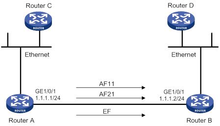
Configuring Router A
# Define three classes to match the IP packets with the DSCP values AF11, AF21, and EF, respectively.
<RouterA> system-view
[RouterA] traffic classifier af11_class
[RouterA-classifier-af11_class] if-match dscp af11
[RouterA-classifier-af11_class] quit
[RouterA]traffic classifier af21_class
[RouterA-classifier-af21_class] if-match dscp af21
[RouterA-classifier-af21_class] quit
[RouterA] traffic classifier ef_class
[RouterA-classifier-ef_class] if-match dscp ef
[RouterA-classifier-ef_class] quit
# Define two traffic behaviors, and enable AF and set a minimum guaranteed bandwidth percentage of 5% in each traffic behavior.
[RouterA] traffic behavior af11_behav
[RouterA-behavior-af11_behav] queue af bandwidth pct 5
[RouterA-behavior-af11_behav] quit
[RouterA] traffic behavior af21_behav
[RouterA-behavior-af21_behav] queue af bandwidth pct 5
[RouterA-behavior-af21_behav] quit
# Define a traffic behavior, and enable EF and set a maximum bandwidth percentage of 30% in the traffic behavior. Both bandwidth and delay are guaranteed for EF traffic.
[RouterA] traffic behavior ef_behav
[RouterA-behavior-ef_behav] queue ef bandwidth pct 30
[RouterA-behavior-ef_behav] quit
# Define a QoS policy and associate the configured traffic behaviors with classes in the QoS policy.
[RouterA] qos policy dscp
[RouterA-qospolicy-dscp] classifier af11_class behavior af11_behav
[RouterA-qospolicy-dscp] classifier af21_class behavior af21_behav
[RouterA-qospolicy-dscp] classifier ef_class behavior ef_behav
[RouterA-qospolicy-dscp] quit
# Apply the QoS policy to the outgoing traffic of GigabitEthernet 1/0/1.
[RouterA] interface gigabitethernet 1/0/1
[RouterA-GigabitEthernet1/0/1] ip address 1.1.1.1 255.255.255.0
[RouterA-GigabitEthernet1/0/1] qos apply policy dscp outbound
The configuration enables EF traffic to be forwarded preferentially when congestion occurs.
Configuring RTPQ
You must configure the rate limit for the queuing feature to take effect on the following interfaces:
· Tunnel interfaces.
· Subinterfaces.
· Layer 3 aggregate interfaces.
· HDLC link bundle interfaces.
· VT and dialer interfaces configured with PPPoE, PPPoA, or PPPoEoA.
To configure RTPQ for an interface or PVC:
|
Step |
Command |
Remarks |
|
1. Enter system view. |
system-view |
N/A |
|
2. Enter interface or PVC view. |
·
Enter interface view: · Enter PVC view: a. interface atm interface-number b. pvc vpi/vci |
N/A |
|
3. Configure RTPQ. |
qos rtpq start-port first-rtp-port-number end-port last-rtp-port-number bandwidth bandwidth [ cbs cbs ] |
By default, RTPQ is not configured. |
Enabling packet information pre-extraction
The IP packets received on the physical interface for a tunnel interface might have been processed by the tunnel interface. For example, if the tunnel interface has used GRE to encapsulate packets, the GRE-encapsulated packets enter the QoS module for processing on the physical interface. As a result, the QoS module cannot get the IP information of the original packets.
To process the original IP packets with QoS on the physical interface for a tunnel interface, configure packet information pre-extraction on the tunnel interface.
To enable packet information pre-extraction:
|
Step |
Command |
Remarks |
|
1. Enter system view. |
system-view |
N/A |
|
2. Enter tunnel interface view. |
interface tunnel number [ mode { ds-lite-aftr | evi [ ipv6 ] | gre [ ipv6 ] | ipv4-ipv4 | ipv6 | ipv6-ipv4 [ 6to4 | auto-tunnel | isatap ] | mpls-te } ] |
Support for tunnel modes depends on the device model. For more information about tunnel interfaces, see Layer 3—IP Services Configuration Guide. |
|
3. Enable packet information pre-extraction. |
qos pre-classify |
By default, packet information pre-extraction is disabled. |
Configuring QoS tokens
This feature is a lower-layer flow control mechanism that controls the length of the lower-layer queue on an interface. The length of the lower-layer queue determines the dequeuing delay of packets. This feature is applicable in the following scenarios:
· When CBQ is used and the interface is congested, the delay in EF queues might fail to meet the requirements because of the buffering of lower-layer queues. This feature can reduce the delay for EF queues when the interface is congested.
· When FTP is used to transmit traffic, QoS queuing might fail to take effect because the upper-layer protocol TCP provides the flow control function. The QoS token feature can solve this problem.
Tune the number of QoS tokens according to the actual conditions to achieve optimal transmission efficiency.
As a best practice to improve the data transmission efficiency, do not configure this feature if the upper-layer protocols (for example, UDP) do not support flow control.
To configure QoS tokens:
|
Step |
Command |
Remarks |
|
1. Enter system view. |
system-view |
N/A |
|
2. Enter interface view. |
interface interface-type interface-number |
Only serial interfaces support this feature. Support for serial interfaces depends on the device model. For more information, see the installation guide. |
|
3. Set the number of QoS tokens. |
qos qmtoken token-number |
By default, the number of QoS tokens is not set. |
|
4. Shut down the interface. |
shutdown |
For the qos qmtoken token-number command to take effect on an interface, execute the shutdown and then undo shutdown commands on the interface after configuring the command. |
|
5. Bring up the interface. |
undo shutdown |
Displaying and maintaining congestion management
Execute display commands in any view and reset commands in user view.
|
Task |
Command |
|
Display queuing configuration and statistics for interfaces or PVCs. |
display qos queue interface [ interface-type interface-number [ pvc { pvc-name | vpi/vci } ] ] |
|
Display queuing configuration and statistics for PWs. |
display qos queue l2vpn-pw [ peer ip-address pw-id pw-id ] |
|
Display the PQ configuration and statistics for interfaces or PVCs. |
display qos queue pq interface [ interface-type interface-number [ pvc { pvc-name | vpi/vci } ] ] |
|
Display the configuration of PQ lists. |
display qos pql [ pql-index ] |
|
Display the CQ configuration and statistics for interfaces or PVCs. |
display qos queue cq interface [ interface-type interface-number [ pvc { pvc-name | vpi/vci } ] ] |
|
Display the configuration of CQ lists. |
display qos cql [ cql-index ] |
|
Display the FIFO configuration and statistics for interfaces, PVCs, or PWs. |
display qos queue fifo { interface [ interface-type interface-number [ pvc { pvc-name | vpi/vci } ] ] | l2vpn-pw [ peer ip-address pw-id pw-id ] } |
|
Display RTPQ configuration. |
display qos queue rtpq interface [ interface-type interface-number [ pvc { pvc-name | vpi/vci } ] ] |
|
Display the WFQ configuration and statistics for interfaces, PVCs, or PWs. |
display qos queue wfq { interface [ interface-type interface-number [ pvc { pvc-name | vpi/vci } ] ] | l2vpn-pw [ peer ip-address pw-id pw-id ] } |
|
Display class configuration. |
display traffic classifier { system-defined | user-defined } [ classifier-name ] |
|
Display traffic behavior configuration. |
display traffic behavior { system-defined | user-defined } [ behavior-name ] |
|
Display QoS policy configuration. |
display qos policy { system-defined | user-defined } [ policy-name [ classifier classifier-name ] ] |
|
Display information about QoS policies applied to interfaces or PVCs (centralized devices in standalone mode). |
display qos policy interface [ interface-type interface-number [ pvc { pvc-name | vpi/vci } ] ] [ inbound | outbound ] |
|
Display information about QoS policies applied to interfaces or PVCs (distributed devices in standalone mode/centralized devices in IRF mode). |
display qos policy interface [ interface-type interface-number [ pvc { pvc-name | vpi/vci } ] ] [ slot slot-number ] [ inbound | outbound ] |
|
Display information about QoS policies applied to interfaces or PVCs (distributed devices in IRF mode). |
display qos policy interface [ interface-type interface-number [ pvc { pvc-name | vpi/vci } ] ] [ chassis chassis-number slot slot-number ] [ inbound | outbound ] |
|
Display the CBQ configuration and statistics for interfaces, PVCs, or PWs. |
display qos queue cbq { interface [ interface-type interface-number [ pvc { pvc-name | vpi/vci } ] ] | l2vpn-pw [ peer ip-address pw-id pw-id ] } |
|
Clear QoS statistics for PWs. |
reset qos statistics l2vpn-pw [ peer ip-address pw-id pw-id ] |
Configuring congestion avoidance
Overview
Avoiding congestion before it occurs is a proactive approach to improving network performance. As a flow control mechanism, congestion avoidance:
· Actively monitors network resources (such as queues and memory buffers).
· Drops packets when congestion is expected to occur or deteriorate.
When dropping packets from a source end, congestion avoidance cooperates with the flow control mechanism at the source end to regulate the network traffic size. The combination of the local packet drop policy and the source-end flow control mechanism implements the following functions:
· Maximizes throughput and network use efficiency.
· Minimizes packet loss and delay.
Tail drop
Congestion management techniques drop all packets that are arriving at a full queue. This tail drop mechanism results in global TCP synchronization. If packets from multiple TCP connections are dropped, these TCP connections go into the state of congestion avoidance and slow start to reduce traffic. However, traffic peak occurs later. Consequently, the network traffic jitters all the time.
RED and WRED
You can use Random Early Detection (RED) or Weighted Random Early Detection (WRED) to avoid global TCP synchronization.
Both RED and WRED avoid global TCP synchronization by randomly dropping packets. When the sending rates of some TCP sessions slow down after their packets are dropped, other TCP sessions remain at high sending rates. Link bandwidth is efficiently used, because TCP sessions at high sending rates always exist.
The RED or WRED algorithm sets an upper threshold and lower threshold for each queue, and processes the packets in a queue as follows:
· When the queue size is shorter than the lower threshold, no packet is dropped.
· When the queue size reaches the upper threshold, all subsequent packets are dropped.
· When the queue size is between the lower threshold and the upper threshold, the received packets are dropped at random. The drop probability in a queue increases along with the queue size under the maximum drop probability.
If the current queue size is compared with the upper threshold and lower threshold to determine the drop policy, burst traffic is not fairly treated. To solve this problem, WRED compares the average queue size with the upper threshold and lower threshold to determine the drop probability.
The average queue size reflects the queue size change trend but is not sensitive to burst queue size changes, and burst traffic can be fairly treated.
When WFQ queuing is used, you can set the following parameters for packets with different precedence values to provide differentiated drop policies:
· Exponent for average queue size calculation.
· Upper threshold.
· Lower threshold.
· Drop probability.
When FIFO, PQ, or CQ is used, you can set the following parameters for each queue to provide differentiated drop policies:
· Exponent for average queue size calculation.
· Upper threshold.
· Lower threshold.
· Drop probability.
Relationship between WRED and queuing mechanisms
Figure 23 Relationship between WRED and queuing mechanisms
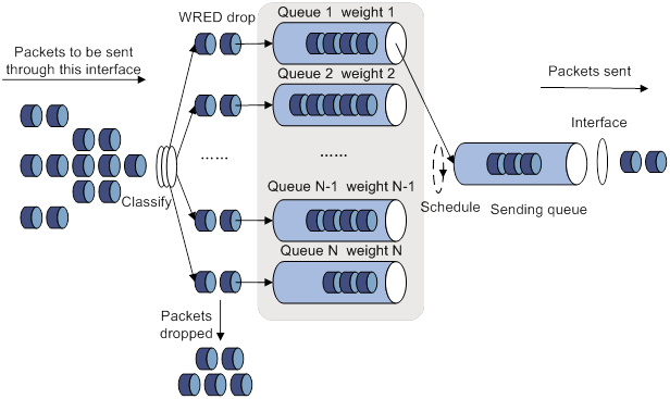
· A flow with a smaller queue size has a lower packet drop probability.
· A flow with a larger queue size has a higher packet drop probability.
In this way, the benefits of the flow with a smaller queue size are protected.
WRED parameters
Determine the following parameters before configuring WRED:
· Upper threshold and lower threshold—When the average queue size is smaller than the lower threshold, packets are not dropped. When the average queue size is between the lower threshold and the upper threshold, the packets are dropped at random. The longer the queue, the higher the drop probability. When the average queue size exceeds the upper threshold, subsequent packets are dropped.
· Drop precedence—A parameter used for packet drop. The value 0 corresponds to green packets, the value 1 corresponds to yellow packets, and the value 2 corresponds to red packets. Red packets are dropped preferentially.
· Exponent for average queue size calculation—The greater the exponent, the less sensitive the average queue size is to real-time queue size changes. The formula for calculating the average queue size is:
Average queue size = ( previous average queue size x (1 – 2–n) ) + (current queue size x 2–n), where n is the exponent.
Configuring WRED on an interface
Configuration procedure
To enable WRED on an interface, you must first enable WFQ on the interface.
To configure WRED on an interface:
|
Step |
Command |
Remarks |
|
1. Enter system view. |
system-view |
N/A |
|
2. Enter interface or PVC view. |
·
Enter interface view: · Enter PVC view: a. interface atm interface-number b. pvc vpi/vci |
N/A |
|
3. Enable WRED. |
qos wred [ dscp | ip-precedence ] enable |
By default, tail drop is adopted. |
|
4. (Optional.) Set the WRED exponent for average queue size calculation. |
qos wred weighting-constant exponent |
The default setting is 9. |
|
5. (Optional.) Set the drop-related parameters for a precedence value. |
qos wred { ip-precedence ip-precedence | dscp dscp-value } low-limit low-limit high-limit high-limit discard-probability discard-prob |
By default, the lower limit is 10, the upper limit is 30, and the drop probability denominator is 10. Repeat this command to configure more precedence values. |
Configuration example
Network requirements
· Enable IP precedence-based WRED on interface GigabitEthernet 1/0/1.
· Set the following parameters for packets with IP precedence 3: lower threshold 20, upper threshold 40, and drop probability 1/15.
· Set the exponent for average queue size calculation to 6.
Configuration procedure
# Enter system view.
<Sysname> system-view
# Enter interface view.
[Sysname] interface gigabitethernet 1/0/1
# Enable IP precedence-based WRED.
[Sysname-GigabitEthernet1/0/1] qos wfq
[Sysname-GigabitEthernet1/0/1] qos wred ip-precedence enable
# Set the following parameters for packets with IP precedence value 3: lower threshold 20, upper threshold 40, and drop probability 1/15.
[Sysname-GigabitEthernet1/0/1] qos wred ip-precedence 3 low-limit 20 high-limit 40 discard-probability 15
# Set the exponent for average queue size calculation to 6.
[Sysname-GigabitEthernet1/0/1] qos wred weighting-constant 6
Displaying and maintaining WRED
Execute display commands in any view.
|
Task |
Command |
|
Display WRED configuration and statistics for an interface or PVC. |
display qos wred interface [ interface-type interface-number [ pvc { pvc-name | vpi/vci } ] ] |
Configuring traffic filtering
You can filter in or filter out traffic of a class by associating the class with a traffic filtering action. For example, you can filter packets sourced from an IP address according to network status.
Configuration procedure
To configure traffic filtering:
|
Step |
Command |
Remarks |
|
1. Enter system view. |
system-view |
N/A |
|
2. Create a traffic class and enter traffic class view. |
traffic classifier classifier-name [ operator { and | or } ] |
By default, no traffic classes exist. |
|
3. Configure a match criterion. |
if-match [ not ] match-criteria |
By default, no match criterion is configured. |
|
4. Return to system view. |
quit |
N/A |
|
5. Create a traffic behavior and enter traffic behavior view. |
traffic behavior behavior-name |
By default, no traffic behaviors exist. |
|
6. Configure the traffic filtering action. |
filter { deny | permit } |
By default, no traffic filtering action is configured. |
|
7. Return to system view. |
quit |
N/A |
|
8. Create a QoS policy and enter QoS policy view. |
qos policy policy-name |
By default, no QoS policies exist. |
|
9. Associate the traffic class with the traffic behavior in the QoS policy. |
classifier classifier-name behavior behavior-name |
By default, a traffic class is not associated with a traffic behavior. |
|
10. Return to system view. |
quit |
N/A |
|
11. Apply the QoS policy. |
· Applying the QoS policy to an interface or PVC · Applying the QoS policy to a control plane |
Choose one of the application destinations as needed. By default, no QoS policy is applied. |
|
12. (Optional.) Display the traffic filtering configuration. |
display traffic behavior user-defined [ behavior-name ] |
Available in any view. |
Configuration example
Network requirements
As shown in Figure 24, configure traffic filtering on GigabitEthernet 1/0/1 to deny the incoming packets with a source port number other than 21.
Configuration procedure
# Create advanced ACL 3000, and configure a rule to match packets whose source port number is not 21.
<Device> system-view
[Device] acl advanced 3000
[Device-acl-ipv4-adv-3000] rule 0 permit tcp source-port neq 21
[Device-acl-ipv4-adv-3000] quit
# Create a traffic class named classifier_1, and use ACL 3000 as the match criterion in the traffic class.
[Device] traffic classifier classifier_1
[Device-classifier-classifier_1] if-match acl 3000
[Device-classifier-classifier_1] quit
# Create a traffic behavior named behavior_1, and configure the traffic filtering action to drop packets.
[Device] traffic behavior behavior_1
[Device-behavior-behavior_1] filter deny
[Device-behavior-behavior_1] quit
# Create a QoS policy named policy, and associate traffic class classifier_1 with traffic behavior behavior_1 in the QoS policy.
[Device] qos policy policy
[Device-qospolicy-policy] classifier classifier_1 behavior behavior_1
[Device-qospolicy-policy] quit
# Apply QoS policy named policy to the incoming traffic of GigabitEthernet 1/0/1.
[Device] interface gigabitethernet 1/0/1
[Device-GigabitEthernet1/0/1] qos apply policy policy inbound
Configuring priority marking
Priority marking sets the priority fields or flag bits of packets to modify the priority of packets. For example, you can use priority marking to set IP precedence or DSCP for a class of IP packets to control the forwarding of these packets.
1. Configure a traffic behavior with a priority marking action.
2. Associate the traffic class with the traffic behavior.
Priority marking can be used together with priority mapping. For more information, see "Configuring priority mapping."
Configuration procedure
To configure priority marking:
|
Step |
Command |
Remarks |
|
1. Enter system view. |
system-view |
N/A |
|
2. Create a traffic class and enter traffic class view. |
traffic classifier classifier-name [ operator { and | or } ] |
By default, no traffic classes exist. |
|
3. Configure a match criterion. |
if-match [ not ] match-criteria |
By default, no match criterion is configured. For more information about the if-match command, see ACL and QoS Command Reference. |
|
4. Return to system view. |
quit |
N/A |
|
5. Create a traffic behavior and enter traffic behavior view. |
traffic behavior behavior-name |
By default, no traffic behaviors exist. |
|
6. Configure a priority marking action. |
·
Set the 802.1p priority for packets: ·
Set the DSCP value for packets: ·
Set the IP precedence for packets: ·
Set the local precedence for packets: ·
Set the local QoS ID for packets: ·
Set the DSCP value in the outer IP header of
tunneled packets: |
Use one of the commands. By default, no priority marking action is configured. The remark tunnel-dscp command takes effect on the following packets: · GRE packets. · VXLAN packets. · IPv4 over IPv4 tunneled packets. · IPv6 over IPv4 tunneled packets. · IPv6 tunneled packets. · MPLS TE tunneled packets. A QoS policy that contains the remark tunnel-dscp command can be applied only to an interface. On devices that forward packets in hardware, the remark tunnel-dscp command is mutually exclusive with the remark dscp or remark ip-precedence command in one traffic behavior. Support for the remark tunnel-dscp command depends on the device model. For more information, see ACL and QoS Command Reference. |
|
7. Return to system view. |
quit |
N/A |
|
8. Create a QoS policy and enter QoS policy view. |
qos policy policy-name |
By default, no QoS policies exist. |
|
9. Associate the traffic class with the traffic behavior in the QoS policy. |
classifier classifier-name behavior behavior-name |
By default, a traffic class is not associated with a traffic behavior. |
|
10. Return to system view. |
quit |
N/A |
|
11. Apply the QoS policy. |
· Applying the QoS policy to an interface or PVC · Applying the QoS policy to a control plane |
Choose one of the application destinations as needed. By default, no QoS policy is applied. |
|
12. (Optional.) Display the priority marking configuration. |
display traffic behavior user-defined [ behavior-name ] |
Available in any view. |
Configuration example
Network requirements
As shown in Figure 25, configure priority marking on the device to meet the following requirements:
|
Traffic source |
Destination |
Processing priority |
|
Host A, B |
Data server |
High |
|
Host A, B |
Mail server |
Medium |
|
Host A, B |
File server |
Low |
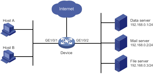
Configuration procedure
# Create advanced ACL 3000, and configure a rule to match packets with destination IP address 192.168.0.1.
<Device> system-view
[Device] acl advanced 3000
[Device-acl-ipv4-adv-3000] rule permit ip destination 192.168.0.1 0
[Device-acl-ipv4-adv-3000] quit
# Create advanced ACL 3001, and configure a rule to match packets with destination IP address 192.168.0.2.
[Device] acl advanced 3001
[Device-acl-ipv4-adv-3001] rule permit ip destination 192.168.0.2 0
[Device-acl-ipv4-adv-3001] quit
# Create advanced ACL 3002, and configure a rule to match packets with destination IP address 192.168.0.3.
[Device] acl advanced 3002
[Device-acl-ipv4-adv-3002] rule permit ip destination 192.168.0.3 0
[Device-acl-ipv4-adv-3002] quit
# Create a traffic class named classifier_dbserver, and use ACL 3000 as the match criterion in the traffic class.
[Device] traffic classifier classifier_dbserver
[Device-classifier-classifier_dbserver] if-match acl 3000
[Device-classifier-classifier_dbserver] quit
# Create a traffic class named classifier_mserver, and use ACL 3001 as the match criterion in the traffic class.
[Device] traffic classifier classifier_mserver
[Device-classifier-classifier_mserver] if-match acl 3001
[Device-classifier-classifier_mserver] quit
# Create a traffic class named classifier_fserver, and use ACL 3002 as the match criterion in the traffic class.
[Device] traffic classifier classifier_fserver
[Device-classifier-classifier_fserver] if-match acl 3002
[Device-classifier-classifier_fserver] quit
# Create a traffic behavior named behavior_dbserver, and configure the action of setting the local precedence value to 4.
[Device] traffic behavior behavior_dbserver
[Device-behavior-behavior_dbserver] remark local-precedence 4
[Device-behavior-behavior_dbserver] quit
# Create a traffic behavior named behavior_mserver, and configure the action of setting the local precedence value to 3.
[Device] traffic behavior behavior_mserver
[Device-behavior-behavior_mserver] remark local-precedence 3
[Device-behavior-behavior_mserver] quit
# Create a traffic behavior named behavior_fserver, and configure the action of setting the local precedence value to 2.
[Device] traffic behavior behavior_fserver
[Device-behavior-behavior_fserver] remark local-precedence 2
[Device-behavior-behavior_fserver] quit
# Create a QoS policy named policy_server, and associate traffic classes with traffic behaviors in the QoS policy.
[Device] qos policy policy_server
[Device-qospolicy-policy_server] classifier classifier_dbserver behavior behavior_dbserver
[Device-qospolicy-policy_server] classifier classifier_mserver behavior behavior_mserver
[Device-qospolicy-policy_server] classifier classifier_fserver behavior behavior_fserver
[Device-qospolicy-policy_server] quit
# Apply QoS policy policy_server to the incoming traffic of GigabitEthernet 1/0/1.
[Device] interface gigabitethernet 1/0/1
[Device-GigabitEthernet1/0/1] qos apply policy policy_server inbound
[Device-GigabitEthernet1/0/1] quit
Configuring traffic redirecting
Traffic redirecting redirects packets matching the specified match criteria to a location for processing.
You can redirect packets to an interface.
Feature and hardware compatibility
This feature is supported only on the following ports:
· Layer 2 Ethernet ports on Ethernet switching modules.
· Fixed Layer 2 Ethernet ports on MSR810/810-W/810-W-DB/810-LM/810-W-LM/810-10-PoE/810-LM-HK/810-W-LM-HK/810-LMS/810-LUS/MSR2600-6-X1/2600-10-X1/MSR3600-28/3600-51/3600-28-SI/3600-51-SI routers/MSR810-LM-GL/810-W-LM-GL/830-6EI-GL/830-10EI-GL/830-6HI-GL/830-10HI-GL/2600-6-X1-GL/3600-28-SI-GL.
Configuration procedure
To configure traffic redirecting:
|
Step |
Command |
Remarks |
|
1. Enter system view. |
system-view |
N/A |
|
2. Create a traffic class and enter traffic class view. |
traffic classifier classifier-name [ operator { and | or } ] |
By default, no traffic classes exist. |
|
3. Configure a match criterion. |
if-match [ not ] match-criteria |
By default, no match criterion is configured for a traffic class. For more information about the match criteria, see the if-match command in ACL and QoS Command Reference. |
|
4. Return to system view. |
quit |
N/A |
|
5. Create a traffic behavior and enter traffic behavior view. |
traffic behavior behavior-name |
By default, no traffic behaviors exist. |
|
6. Configure a traffic redirecting action. |
redirect interface interface-type interface-number [ track-oap ] |
By default, no traffic redirecting action is configured for a traffic behavior. |
|
7. Return to system view. |
quit |
N/A |
|
8. Create a QoS policy and enter QoS policy view. |
qos policy policy-name |
By default, no QoS policies exist. |
|
9. Associate the traffic class with the traffic behavior in the QoS policy. |
classifier classifier-name behavior behavior-name |
By default, a traffic class is not associated with a traffic behavior. |
|
10. Return to system view. |
quit |
N/A |
|
11. Apply the QoS policy. |
· Applying the QoS policy to an interface or PVC · Applying the QoS policy to a control plane |
Choose one of the application destinations as needed. By default, no QoS policy is applied. |
|
12. (Optional.) Display traffic redirecting configuration. |
display traffic behavior user-defined [ behavior-name ] |
Available in any view. |
Configuration example
Network requirements
As shown in Figure 26, packets from network segments 2.2.2.0/24 and 3.3.3.0/24 enter the device through GigabitEthernet 2/1/0.
Configure traffic redirecting on GigabitEthernet 2/1/0 to meet the following requirements:
· Packets from network segment 2.2.2.0/24 are forwarded to GigabitEthernet 2/1/1.
· Packets from network segment 3.3.3.0/24 are forwarded to GigabitEthernet 2/1/2.
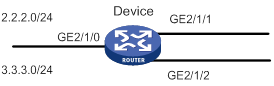
Configuration procedure
# Create basic ACL 2000, and configure a rule to match packets from network segment 2.2.2.0/24.
<Device> system-view
[Device] acl basic 2000
[Device-acl-ipv4-basic-2000] rule permit source 2.2.2.0 0.0.0.255
[Device-acl-ipv4-basic-2000] quit
# Create basic ACL 2001, and configure a rule to match packets from network segment 3.3.3.0/24.
[Device] acl basic 2001
[Device-acl-ipv4-basic-2001] rule permit source 3.3.3.0 0.0.0.255
[Device-acl-ipv4-basic-2001] quit
# Create a traffic class named classifier_1, and use ACL 2000 as the match criterion in the traffic class.
[Device] traffic classifier classifier_1
[Device-classifier-classifier_1] if-match acl 2000
[Device-classifier-classifier_1] quit
# Create a traffic class named classifier_2, and use ACL 2001 as the match criterion in the traffic class.
[Device] traffic classifier classifier_2
[Device-classifier-classifier_2] if-match acl 2001
[Device-classifier-classifier_2] quit
# Create a traffic behavior named behavior_1, and configure the action of redirecting traffic to GigabitEthernet 2/1/2.
[Device] traffic behavior behavior_1
[Device-behavior-behavior_1] redirect interface gigabitethernet 2/1/2
[Device-behavior-behavior_1] quit
# Create a traffic behavior named behavior_2, and configure the action of redirecting traffic to GigabitEthernet 2/1/3.
[Device] traffic behavior behavior_2
[Device-behavior-behavior_2] redirect interface gigabitethernet 2/1/3
[Device-behavior-behavior_2] quit
# Create a QoS policy named policy.
[Device] qos policy policy
# Associate traffic class classifier_1 with traffic behavior behavior_1 in the QoS policy.
[Device-qospolicy-policy] classifier classifier_1 behavior behavior_1
# Associate traffic class classifier_2 with traffic behavior behavior_2 in the QoS policy.
[Device-qospolicy-policy] classifier classifier_2 behavior behavior_2
[Device-qospolicy-policy] quit
# Apply the QoS policy named policy to the incoming traffic of GigabitEthernet 2/1/1.
[Device] interface gigabitethernet 2/1/1
[Device-GigabitEthernet2/1/1] qos apply policy policy inbound
Configuring QPPB
The term "router" in this document refers to both routers and Layer 3 switches.
Overview
The QoS Policy Propagation Through the Border Gateway Protocol (QPPB) feature enables you to classify IP packets based on the following attributes:
· BGP community lists.
· Prefix lists.
· BGP AS paths.
The QPPB feature is implemented as follows:
· The BGP route sender preclassifies routes before advertising them.
· The BGP route receiver performs the following operations:
? Sets the IP precedence and local QoS ID for the routes.
? Takes appropriate QoS actions on the packets that match the routes.
QPPB minimizes the QoS policy configuration and management efforts on the BGP route receiver when the network topology changes. It is suitable for a large-scaled complex network that classifies packets based on source or destination IP addresses for QoS.
QPPB applies to IBGP and EBGP. You can use it within an autonomous system or across multiple autonomous systems.
QPPB fundamentals
QPPB works on the BGP receiver. It depends on the BGP route sender to preclassify routes.
The BGP route sender uses a routing policy to set route attributes for BGP routes before advertising them.
The BGP receiver performs the following operations:
· Uses a routing policy to match routes based on these route attributes.
· Sets IP precedence and local QoS ID for the matching routes.
The BGP receiver performs the following operations:
1. Compares the routes with the incoming route policy based on their BGP AS path, prefix, or community attributes.
2. Applies the IP precedence and local QoS ID to the matching routes.
3. Adds the BGP routes and their associated IP precedence and local QoS ID to the routing table.
4. Applies the IP precedence and local QoS ID to the packets sourced from or destined to the IP address in the route.
5. Takes QoS actions on the packets according to the QoS priority settings.
QPPB configuration task list
|
Tasks at a glance |
|
Configuring the route sender: · (Required.) Configuring basic BGP functions · (Optional.) Creating a routing policy |
|
Configuring the route receiver: · (Required.) Configuring basic BGP functions · (Required.) Configuring a routing policy · (Required.) Enabling QPPB on the route receiving interface · (Required.) Configuring a QoS policy · (Required.) Applying the QoS policy to an interface |
Configuring the route sender
Configure the BGP route sender to set route attributes for routes before advertising them.
Configuring basic BGP functions
For more information, see Layer 3—IP Routing Configuration Guide.
Creating a routing policy
Configuring the route receiver
Configuring basic BGP functions
For more information, see Layer 3—IP Routing Configuration Guide.
Configuring a routing policy
Configure a routing policy to perform the following operations:
· Match the route attributes set by the route sender.
· Set the IP precedence, local QoS ID, or both for the matching routes.
For more information, see Layer 3—IP Routing Configuration Guide.
Enabling QPPB on the route receiving interface
|
Command |
Remarks |
|
|
1. Enter system view. |
system-view |
N/A |
|
2. Enter interface view. |
interface interface-type interface-number |
N/A |
|
3. Enable QPPB on the interface. |
bgp-policy { destination | source } { ip-prec-map | ip-qos-map } * |
By default, QPPB is disabled. This command applies only to incoming traffic. |
Configuring a QoS policy
Applying the QoS policy to an interface
|
Step |
Command |
Remarks |
|
1. Enter system view. |
system-view |
N/A |
|
2. Enter interface view. |
interface interface-type interface-number |
N/A |
|
3. Apply the specified policy to the interface. |
qos apply policy policy-name { inbound | outbound } |
By default, no QoS policy is applied. |
QPPB configuration examples
QPPB configuration example in an IPv4 network
Network requirements
As shown in Figure 27, all routers run BGP.
Configure QPPB so that Router B can perform the following operations:
· Receive routes.
· Set IP precedence values and local QoS IDs according to the routing policy.
· Use the QoS policy to limit the traffic rate to 512 kbps.
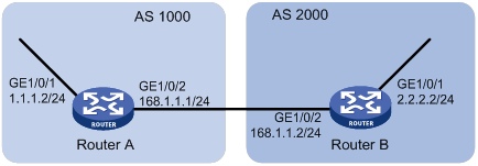
Configuration procedure
1. Configure IP addresses for each interface. (Details not shown.)
2. Configure a BGP connection to Router B, and add the network 1.1.1.0/8 to the BGP routing table on Router A.
<RouterA> system-view
[RouterA] bgp 1000
[RouterA-bgp] peer 168.1.1.2 as-number 2000
[RouterA-bgp] peer 168.1.1.2 connect-interface GigabitEthernet 1/0/2
[RouterA-bgp] address-family ipv4
[RouterA-bgp-ipv4] import-route direct
[RouterA-bgp-ipv4] peer 168.1.1.2 enable
[RouterA-bgp-ipv4] quit
[RouterA-bgp] quit
3. Configure Router B:
# Configure a BGP connection to Router A.
[RouterB] bgp 2000
[RouterB-bgp] peer 168.1.1.1 as-number 1000
[RouterB-bgp] peer 168.1.1.1 connect-interface GigabitEthernet 1/0/2
[RouterB-bgp] address-family ipv4
[RouterB-bgp-ipv4] peer 168.1.1.1 enable
[RouterB-bgp-ipv4] peer 168.1.1.1 route-policy qppb import
[RouterB-bgp-ipv4] quit
[RouterB-bgp] quit
# Configure a routing policy named qppb.
[RouterB] route-policy qppb permit node 0
[RouterB-route-policy-qppb-0] apply ip-precedence 1
[RouterB-route-policy-qppb-0] apply qos-local-id 3
[RouterB-route-policy-qppb-0] quit
# Enable QPPB on interface GigabitEthernet 1/0/2.
[RouterB] interface gigabitethernet 1/0/2
[RouterB-GigabitEthernet1/0/2] bgp-policy source ip-prec-map ip-qos-map
[RouterB-GigabitEthernet1/0/2] quit
# Configure a QoS policy named qppb.
[RouterB] traffic classifier qppb
[RouterB-classifier-qppb] if-match ip-precedence 1
[RouterB-classifier-qppb] if-match qos-local-id 3
[RouterB-classifier-qppb] quit
[RouterB] traffic behavior qppb
[RouterB-behavior-qppb] car cir 512 green pass red discard
[RouterB-behavior-qppb] quit
[RouterB] qos policy qppb
[RouterB-qospolicy-qppb] classifier qppb behavior qppb
[RouterB-qospolicy-qppb] quit
# Apply QoS policy qppb to incoming traffic on interface GigabitEthernet 1/0/2.
[RouterB] interface gigabitethernet 1/0/2
[RouterB-GigabitEthernet1/0/2] qos apply policy qppb inbound
[RouterB-GigabitEthernet1/0/2] quit
Verifying the configuration
# Verify that the related route on Router B takes effect.
[RouterB] display ip routing-table 1.1.1.0 24 verbose
Summary Count : 1
Destination: 1.1.1.0/24
Protocol: BGP
Process ID: 0
SubProtID: 0x2 Age: 00h00m33s
Cost: 0 Preference: 255
IpPre: 1 QosLocalID: 3
Tag: 0 State: Active Adv
OrigTblID: 0x0 OrigVrf: default-vrf
TableID: 0x2 OrigAs: 1000
NibID: 0x15000000 LastAs: 1000
AttrID: 0x0 Neighbor: 168.1.1.1
Flags: 0x10060 OrigNextHop: 168.1.1.1
Label: NULL RealNextHop: 168.1.1.1
BkLabel: NULL BkNextHop: N/A
Tunnel ID: Invalid Interface: GigabitEthernet1/0/2
BkTunnel ID: Invalid BkInterface: N/A
FtnIndex: 0x0 TrafficIndex: N/A
Connector: N/A VpnPeerId:
N/A
Dscp: N/A
# Display the QoS policy configuration on GigabitEthernet1/0/2 of Router B.
[RouterB] display qos policy interface gigabitethernet 1/0/2
Interface: GigabitEthernet1/0/2
Direction: Inbound
Policy: qppb
Classifier: default-class
Matched : 51 (Packets) 4022 (Bytes)
5-minute statistics:
Forwarded: 0/28 (pps/bps)
Dropped : 0/0 (pps/bps)
Operator: AND
Rule(s) :
If-match any
Behavior: be
-none-
Classifier: qppb
Matched : 0 (Packets) 0 (Bytes)
5-minute statistics:
Forwarded: 0/0 (pps/bps)
Dropped : 0/0 (pps/bps)
Operator: AND
Rule(s) :
If-match ip-precedence 1
If-match qos-local-id 3
Behavior: qppb
Committed Access Rate:
CIR 512 (kbps), CBS 32000 (Bytes), EBS 512 (Bytes)
Green action : pass
Yellow action : pass
Red action : discard
Green packets : 0 (Packets) 0 (Bytes)
Yellow packets: 0 (Packets) 0 (Bytes)
Red packets : 0 (Packets) 0 (Bytes)
QPPB configuration example in an MPLS L3VPN
Network requirements
As shown in Figure 28, all routers run BGP.
Configure QPPB so that Router C can perform the following operations:
· Receive routes.
· Set the QPPB local QoS IDs.
· Use the QoS policy to limit the traffic rate to 2 Mbps in each direction.
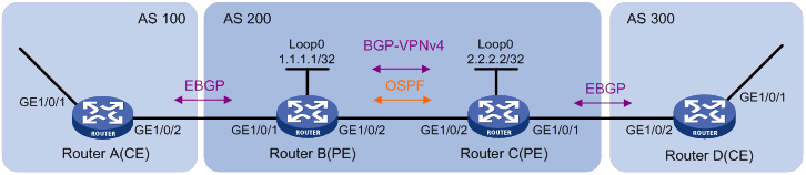
Table 4 Interfaces and IP address assignment
|
Device |
Interface |
IP address |
Device |
Interface |
IP address |
|
Router A |
GE1/0/1 |
192.168.1.2/24 |
Router B |
GE1/0/1 |
167.1.1.2/24 |
|
GE1/0/2 |
167.1.1.1/24 |
GE1/0/2 |
168.1.1.2/24 |
||
|
Router C |
GE1/0/1 |
169.1.1.2/24 |
Router D |
GE1/0/2 |
169.1.1.1/24 |
|
GE1/0/2 |
168.1.1.1/24 |
GE1/0/1 |
192.168.3.2/24 |
Configuration procedure
1. Configure IP addresses for each interface. (Details not shown.)
2. Configure a BGP connection on Router A.
[RouterA] bgp 100
[RouterA-bgp] peer 167.1.1.2 as-number 200
[RouterA-bgp] peer 167.1.1.2 connect-interface gigabitethernet 1/0/2
[RouterA-bgp] address-family ipv4
[RouterA-bgp-ipv4] import-route direct
[RouterA-bgp-ipv4] peer 167.1.1.2 enable
[RouterA-bgp-ipv4] quit
[RouterA-bgp] quit
3. Configure Router B:
# Configure a VPN instance.
[RouterB] ip vpn-instance vpn1
[RouterB-vpn-instance-vpn1] route-distinguisher 200:1
[RouterB-vpn-instance-vpn1] vpn-target 200:1 export-extcommunity
[RouterB-vpn-instance-vpn1] vpn-target 200:1 import-extcommunity
[RouterB-vpn-instance-vpn1] quit
# Configure a BGP connection.
[RouterB] bgp 200
[RouterB-bgp] peer 2.2.2.2 as-number 200
[RouterB-bgp] peer 2.2.2.2 connect-interface loopback 0
[RouterB-bgp] ip vpn-instance vpn1
[RouterB-bgp-vpn1] peer 167.1.1.1 as-number 100
[RouterB-bgp-vpn1] address-family ipv4
[RouterB-bgp-ipv4-vpn1] peer 167.1.1.1 enable
[RouterB-bgp-ipv4-vpn1] quit
[RouterB-bgp] address-family vpnv4
[RouterB-bgp-vpnv4] peer 2.2.2.2 enable
[RouterB-bgp-vpnv4] quit
[RouterB-bgp] quit
# Configure MPLS.
[RouterB] mpls ldp
[RouterB-mpls-ldp] quit
# Configure OSPF.
[RouterB-ospf-1] area 0
[RouterB-ospf-1-area-0.0.0.0] network 1.1.1.1 0.0.0.0
[RouterB-ospf-1-area-0.0.0.0] network 168.1.1.0 0.0.0.255
[RouterB-ospf-1-area-0.0.0.0] quit
[RouterB-ospf-1] quit
# Bind interface GigabitEthernet 1/0/1 to VPN instance vpn1.
[RouterB] interface gigabitethernet 1/0/1
[RouterB-GigabitEthernet1/0/1] ip binding vpn-instance vpn1
[RouterB-GigabitEthernet1/0/1] ip address 167.1.1.2 24
[RouterB-GigabitEthernet1/0/1] quit
# Enable MPLS on interface GigabitEthernet 1/0/2.
[RouterB] interface gigabitethernet 1/0/2
[RouterB-GigabitEthernet1/0/2] mpls enable
[RouterB-GigabitEthernet1/0/2] mpls ldp enable
[RouterB-GigabitEthernet1/0/2] quit
4. Configure Router C:
# Configure a VPN instance.
[RouterC] ip vpn-instance vpn1
[RouterC-vpn-instance-vpn1] route-distinguisher 200:1
[RouterC-vpn-instance-vpn1] vpn-target 200:1 export-extcommunity
[RouterC-vpn-instance-vpn1] vpn-target 200:1 import-extcommunity
[RouterC-vpn-instance-vpn1] quit
# Configure a BGP connection.
[RouterC] bgp 200
[RouterC-bgp] peer 1.1.1.1 as-number 200
[RouterC-bgp] peer 1.1.1.1 connect-interface loopback 0
[RouterC-bgp] ip vpn-instance vpn1
[RouterC-bgp-vpn1] peer 169.1.1.1 as-number 300
[RouterC-bgp-vpn1] address-family ipv4
[RouterC-bgp-ipv4-vpn1] peer 169.1.1.1 enable
[RouterC-bgp-ipv4-vpn1] peer 169.1.1.1 route-policy qppb import
[RouterC-bgp-ipv4-vpn1] quit
[RouterC-bgp-vpn1] quit
[RouterC-bgp] address-family vpnv4
[RouterC-bgp-vpnv4] peer 1.1.1.1 enable
[RouterC-bgp-vpnv4] peer 1.1.1.1 route-policy qppb import
[RouterC-bgp-vpnv4] quit
[RouterC-bgp] quit
# Configure a routing policy named qppb.
[RouterC] route-policy qppb permit node 0
[RouterC-route-policy-qppb-0] apply qos-local-id 1023
[RouterC-route-policy-qppb-0] quit
# Configure MPLS.
[RouterC] mpls ldp
[RouterC-mpls-ldp] quit
# Configure OSPF.
[RouterC-ospf-1] area 0
[RouterC-ospf-1-area-0.0.0.0] network 2.2.2.2 0.0.0.0
[RouterC-ospf-1-area-0.0.0.0] network 168.1.1.0 0.0.0.255
[RouterC-ospf-1-area-0.0.0.0] quit
[RouterC-ospf-1] quit
# Configure a QoS policy named qppb.
[RouterC] traffic classifier qppb
[RouterC-classifier-qppb] if-match qos-local-id 1023
[RouterC-classifier-qppb] quit
[RouterC] traffic behavior qppb
[RouterC-behavior-qppb] car cir 2000 green pass red discard
[RouterC-behavior-qppb] quit
[RouterC] qos policy qppb
[RouterC-qospolicy-qppb] classifier qppb behavior qppb
[RouterC-qospolicy-qppb] quit
# Enable MPLS on interface GigabitEthernet 1/0/2.
[RouterC] interface gigabitethernet 1/0/2
[RouterC-GigabitEthernet1/0/2] mpls enable
[RouterC-GigabitEthernet1/0/2] mpls ldp enable
# Enable QPPB on GigabitEthernet 1/0/1 and GigabitEthernet 1/0/2.
[RouterC-GigabitEthernet1/0/2] bgp-policy destination ip-qos-map
[RouterC-GigabitEthernet1/0/2] quit
[RouterC] interface gigabitethernet 1/0/1
[RouterC-GigabitEthernet1/0/1] bgp-policy destination ip-qos-map
[RouterC-GigabitEthernet1/0/1] quit
# Bind GigabitEthernet 1/0/1 to VPN instance vpn1.
[RouterC] interface gigabitethernet 1/0/1
[RouterC-GigabitEthernet1/0/1] ip binding vpn-instance vpn1
[RouterC-GigabitEthernet1/0/1] ip address 169.1.1.2 24
# Apply the QoS policy qppb to the incoming and outgoing traffic of GigabitEthernet 1/0/1.
[RouterC-GigabitEthernet1/0/1] qos apply policy qppb inbound
[RouterC-GigabitEthernet1/0/1] qos apply policy qppb outbound
5. Configure a BGP connection on Router D.
[RouterD] bgp 300
[RouterD-bgp] peer 169.1.1.2 as-number 200
[RouterD-bgp] peer 169.1.1.2 connect-interface gigabitethernet 1/0/2
[RouterD-bgp] address-family ipv4
[RouterD-bgp-ipv4] peer 169.1.1.2 enable
[RouterD-bgp-ipv4] import-route direct
[RouterD-bgp-ipv4] quit
Verifying the configuration
# Verify that the related routes on Router A take effect.
[RouterA] display ip routing-table
Destinations : 18 Routes : 18
Destination/Mask Proto Pre Cost NextHop Interface
0.0.0.0/32 Direct 0 0 127.0.0.1 InLoop0
127.0.0.0/8 Direct 0 0 127.0.0.1 InLoop0
127.0.0.0/32 Direct 0 0 127.0.0.1 InLoop0
127.0.0.1/32 Direct 0 0 127.0.0.1 InLoop0
127.255.255.255/32 Direct 0 0 127.0.0.1 InLoop0
167.1.1.0/24 Direct 0 0 167.1.1.1 GE1/0/2
167.1.1.0/32 Direct 0 0 167.1.1.1 GE1/0/2
167.1.1.1/32 Direct 0 0 127.0.0.1 InLoop0
167.1.1.255/32 Direct 0 0 167.1.1.1 GE1/0/2
169.1.1.0/24 BGP 255 0 167.1.1.2 GE1/0/2
192.168.1.0/24 Direct 0 0 192.168.1.2 GE1/0/1
192.168.1.0/32 Direct 0 0 192.168.1.2 GE1/0/1
192.168.1.2/32 Direct 0 0 127.0.0.1 InLoop0
192.168.1.255/32 Direct 0 0 192.168.1.2 GE1/0/1
192.168.3.0/24 BGP 255 0 167.1.1.2 GE1/0/2
224.0.0.0/4 Direct 0 0 0.0.0.0 NULL0
224.0.0.0/24 Direct 0 0 0.0.0.0 NULL0
255.255.255.255/32 Direct 0 0 127.0.0.1 InLoop0
# Verify that the related routes on Router B take effect.
[RouterB] display ip routing-table
Destinations : 14 Routes : 14
Destination/Mask Proto Pre Cost NextHop Interface
0.0.0.0/32 Direct 0 0 127.0.0.1 InLoop0
1.1.1.1/32 Direct 0 0 127.0.0.1 InLoop0
2.2.2.2/32 OSPF 10 1 168.1.1.1 GE1/0/2
127.0.0.0/8 Direct 0 0 127.0.0.1 InLoop0
127.0.0.0/32 Direct 0 0 127.0.0.1 InLoop0
127.0.0.1/32 Direct 0 0 127.0.0.1 InLoop0
127.255.255.255/32 Direct 0 0 127.0.0.1 InLoop0
168.1.1.0/24 Direct 0 0 168.1.1.2 GE1/0/2
168.1.1.0/32 Direct 0 0 168.1.1.2 GE1/0/2
168.1.1.2/32 Direct 0 0 127.0.0.1 InLoop0
168.1.1.255/32 Direct 0 0 168.1.1.2 GE1/0/2
224.0.0.0/4 Direct 0 0 0.0.0.0 NULL0
224.0.0.0/24 Direct 0 0 0.0.0.0 NULL0
255.255.255.255/32 Direct 0 0 127.0.0.1 InLoop0
[RouterB] display ip routing-table vpn-instance vpn1
Destinations : 16 Routes : 16
Destination/Mask Proto Pre Cost NextHop Interface
0.0.0.0/32 Direct 0 0 127.0.0.1 InLoop0
127.0.0.0/8 Direct 0 0 127.0.0.1 InLoop0
127.0.0.0/32 Direct 0 0 127.0.0.1 InLoop0
127.0.0.1/32 Direct 0 0 127.0.0.1 InLoop0
127.255.255.255/32 Direct 0 0 127.0.0.1 InLoop0
167.1.1.0/24 Direct 0 0 167.1.1.2 GE1/0/1
167.1.1.0/32 Direct 0 0 167.1.1.2 GE1/0/1
167.1.1.2/32 Direct 0 0 127.0.0.1 InLoop0
167.1.1.255/32 Direct 0 0 167.1.1.2 GE1/0/1
169.1.1.0/24 BGP 255 0 2.2.2.2 GE1/0/2
192.168.1.0/24 BGP 255 0 167.1.1.1 GE1/0/1
192.168.2.0/24 BGP 255 0 167.1.1.1 GE1/0/1
192.168.3.0/24 BGP 255 0 2.2.2.2 GE1/0/2
224.0.0.0/4 Direct 0 0 0.0.0.0 NULL0
224.0.0.0/24 Direct 0 0 0.0.0.0 NULL0
255.255.255.255/32 Direct 0 0 127.0.0.1 InLoop0
# Verify that the related routes on Router C take effect.
[RouterC] display ip routing-table
Destinations : 14 Routes : 14
Destination/Mask Proto Pre Cost NextHop Interface
0.0.0.0/32 Direct 0 0 127.0.0.1 InLoop0
1.1.1.1/32 OSPF 10 1 168.1.1.2 GE1/0/2
2.2.2.2/32 Direct 0 0 127.0.0.1 InLoop0
127.0.0.0/8 Direct 0 0 127.0.0.1 InLoop0
127.0.0.0/32 Direct 0 0 127.0.0.1 InLoop0
127.0.0.1/32 Direct 0 0 127.0.0.1 InLoop0
127.255.255.255/32 Direct 0 0 127.0.0.1 InLoop0
168.1.1.0/24 Direct 0 0 168.1.1.1 GE1/0/2
168.1.1.0/32 Direct 0 0 168.1.1.1 GE1/0/2
168.1.1.1/32 Direct 0 0 127.0.0.1 InLoop0
168.1.1.255/32 Direct 0 0 168.1.1.1 GE1/0/2
224.0.0.0/4 Direct 0 0 0.0.0.0 NULL0
224.0.0.0/24 Direct 0 0 0.0.0.0 NULL0
255.255.255.255/32 Direct 0 0 127.0.0.1 InLoop0
[RouterC] display ip routing-table vpn-instance vpn1
Destinations : 16 Routes : 16
Destination/Mask Proto Pre Cost NextHop Interface
0.0.0.0/32 Direct 0 0 127.0.0.1 InLoop0
127.0.0.0/8 Direct 0 0 127.0.0.1 InLoop0
127.0.0.0/32 Direct 0 0 127.0.0.1 InLoop0
127.0.0.1/32 Direct 0 0 127.0.0.1 InLoop0
127.255.255.255/32 Direct 0 0 127.0.0.1 InLoop0
167.1.1.0/24 BGP 255 0 1.1.1.1 GE1/0/2
169.1.1.0/24 Direct 0 0 169.1.1.2 GE1/0/1
169.1.1.0/32 Direct 0 0 169.1.1.2 GE1/0/1
169.1.1.2/32 Direct 0 0 127.0.0.1 InLoop0
169.1.1.255/32 Direct 0 0 169.1.1.2 GE1/0/1
192.168.1.0/24 BGP 255 0 1.1.1.1 GE1/0/2
192.168.2.0/24 BGP 255 0 169.1.1.1 GE1/0/1
192.168.3.0/24 BGP 255 0 169.1.1.1 GE1/0/1
224.0.0.0/4 Direct 0 0 0.0.0.0 NULL0
224.0.0.0/24 Direct 0 0 0.0.0.0 NULL0
255.255.255.255/32 Direct 0 0 127.0.0.1 InLoop0
# Verify that the related routes on Router D take effect.
[RouterD] display ip routing-table
Destinations : 18 Routes : 18
Destination/Mask Proto Pre Cost NextHop Interface
0.0.0.0/32 Direct 0 0 127.0.0.1 InLoop0
127.0.0.0/8 Direct 0 0 127.0.0.1 InLoop0
127.0.0.0/32 Direct 0 0 127.0.0.1 InLoop0
127.0.0.1/32 Direct 0 0 127.0.0.1 InLoop0
127.255.255.255/32 Direct 0 0 127.0.0.1 InLoop0
167.1.1.0/24 BGP 255 0 169.1.1.2 GE1/0/2
169.1.1.0/24 Direct 0 0 169.1.1.1 GE1/0/2
169.1.1.0/32 Direct 0 0 169.1.1.1 GE1/0/2
169.1.1.1/32 Direct 0 0 127.0.0.1 InLoop0
169.1.1.255/32 Direct 0 0 169.1.1.1 GE1/0/2
192.168.1.0/24 BGP 255 0 169.1.1.2 GE1/0/2
192.168.3.0/24 Direct 0 0 192.168.3.2 GE1/0/1
192.168.3.0/32 Direct 0 0 192.168.3.2 GE1/0/1
192.168.3.2/32 Direct 0 0 127.0.0.1 InLoop0
192.168.3.255/32 Direct 0 0 192.168.3.2 GE1/0/1
224.0.0.0/4 Direct 0 0 0.0.0.0 NULL0
224.0.0.0/24 Direct 0 0 0.0.0.0 NULL0
255.255.255.255/32 Direct 0 0 127.0.0.1 InLoop0
# Display the QoS policy configuration on interface GigabitEthernet 1/0/1 of Router C.
[RouterC] display qos policy interface gigabitethernet 1/0/1
Interface: GigabitEthernet1/0/1
Direction: Inbound
Policy: qppb
Classifier: default-class
Matched : 312 (Packets) 18916 (Bytes)
5-minute statistics:
Forwarded: 0/24 (pps/bps)
Dropped : 0/0 (pps/bps)
Operator: AND
Rule(s) :
If-match any
Behavior: be
-none-
Classifier: qppb
Matched : 0 (Packets) 0 (Bytes)
5-minute statistics:
Forwarded: 0/0 (pps/bps)
Dropped : 0/0 (pps/bps)
Operator: AND
Rule(s) :
If-match qos-local-id 1023
Behavior: qppb
Committed Access Rate:
CIR 2000 (kbps), CBS 125000 (Bytes), EBS 512 (Bytes)
Green action : pass
Yellow action : pass
Red action : discard
Green packets : 0 (Packets) 0 (Bytes)
Yellow packets: 0 (Packets) 0 (Bytes)
Red packets : 0 (Packets) 0 (Bytes)
Interface: GigabitEthernet1/0/1
Direction: Outbound
Policy: qppb
Classifier: default-class
Matched : 311 (Packets) 23243 (Bytes)
5-minute statistics:
Forwarded: 0/24 (pps/bps)
Dropped : 0/0 (pps/bps)
Operator: AND
Rule(s) :
If-match any
Behavior: be
-none-
Classifier: qppb
Matched : 0 (Packets) 0 (Bytes)
5-minute statistics:
Forwarded: 0/0 (pps/bps)
Dropped : 0/0 (pps/bps)
Operator: AND
Rule(s) :
If-match qos-local-id 1023
Behavior: qppb
Committed Access Rate:
CIR 2000 (kbps), CBS 125000 (Bytes), EBS 512 (Bytes)
Green action : pass
Yellow action : pass
Red action : discard
Green packets : 0 (Packets) 0 (Bytes)
Yellow packets: 0 (Packets) 0 (Bytes)
Red packets : 0 (Packets) 0 (Bytes)
QPPB configuration example in an IPv6 network
Network requirements
As shown in Figure 29, all routers run BGP.
Configure QPPB so that Router B can perform the following operations:
· Receive routes.
· Set the QPPB IP precedence value.
· Use the QoS policy to limit the rate of traffic with the IP precedence value to 512 kbps.
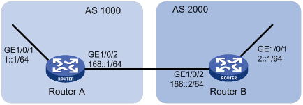
Configuration procedure
1. Configure IPv6 addresses for each interface. (Details not shown.)
2. Configure BGP on Router A.
[RouterA] bgp 1000
[RouterA] peer 168::2 as-number 2000
[RouterA] peer 168::2 connect-interface gigabitethernet 1/0/2
[RouterA-bgp] address-family ipv6
[RouterA-bgp-ipv6] peer 168::2 enable
[RouterA-bgp-ipv6] import-route direct
[RouterA-bgp-ipv6] quit
[RouterA-bgp] quit
3. Configure Router B:
# Configure BGP.
[RouterB] bgp 2000
[RouterB] peer 168::1 as-number 1000
[RouterB] peer 168::1 connect-interface gigabitethernet 1/0/2
[RouterB-bgp] address-family ipv6
[RouterB-bgp-ipv6] peer 168::1 enable
[RouterB-bgp-ipv6] peer 168::1 route-policy qppb import
[RouterB-bgp-ipv6] quit
[RouterB-bgp] quit
# Configure a routing policy.
[RouterB] route-policy qppb permit node 0
[RouterB-route-policy-qppb-0] apply ip-precedence 4
[RouterB-route-policy-qppb-0] quit
# Enable QPPB on interface GigabitEthernet 1/0/1.
[RouterB] interface gigabitethernet 1/0/1
[RouterB-GigabitEthernet1/0/1] bgp-policy destination ip-prec-map
# Configure a QoS policy.
[RouterB] traffic classifier qppb
[RouterB-classifier-qppb] if-match ip-precedence 4
[RouterB-classifier-qppb] quit
[RouterB] traffic behavior qppb
[RouterB-behavior-qppb] car cir 512 red discard
[RouterB-behavior-qppb] quit
[RouterB] qos policy qppb
[RouterB-qospolicy-qppb] classifier qppb behavior qppb
[RouterB-qospolicy-qppb] quit
# Apply the QoS policy to the incoming traffic of GigabitEthernet 1/0/1.
[RouterB] interface gigabitethernet 1/0/1
[RouterB-GigabitEthernet1/0/1] qos apply policy qppb inbound
[RouterB-GigabitEthernet1/0/1] quit
Verifying the configuration
# Verify that the related routes on Router A take effect.
[RouterA] display ipv6 routing-table
Destinations : 7 Routes : 7
Destination: ::1/128 Protocol : Direct
NextHop : ::1 Preference: 0
Interface : InLoop0 Cost : 0
Destination: 1::/64 Protocol : Direct
NextHop : :: Preference: 0
Interface : GE1/0/1 Cost : 0
Destination: 1::1/128 Protocol : Direct
NextHop : ::1 Preference: 0
Interface : InLoop0 Cost : 0
Destination: 168::/64 Protocol : Direct
NextHop : :: Preference: 0
Interface : GE1/0/2 Cost : 0
Destination: 168::1/128 Protocol : Direct
NextHop : ::1 Preference: 0
Interface : InLoop0 Cost : 0
Destination: FE80::/10 Protocol : Direct
NextHop : :: Preference: 0
Interface : NULL0 Cost : 0
Destination: FF00::/8 Protocol : Direct
NextHop : :: Preference: 0
Interface : NULL0 Cost : 0
# Verify that the related routes on Router B take effect.
[RouterB] display ipv6 routing-table
Destinations : 9 Routes : 9
Destination: ::1/128 Protocol : Direct
NextHop : ::1 Preference: 0
Interface : InLoop0 Cost : 0
Destination: 1::/64 Protocol : BGP4+
NextHop : 168::1 Preference: 255
Interface : GE1/0/2 Cost : 0
Destination: 2::/64 Protocol : Direct
NextHop : :: Preference: 0
Interface : GE1/0/1 Cost : 0
Destination: 2::1/128 Protocol : Direct
NextHop : ::1 Preference: 0
Interface : InLoop0 Cost : 0
Destination: 2::2/128 Protocol : Direct
NextHop : ::1 Preference: 0
Interface : InLoop0 Cost : 0
Destination: 168::/64 Protocol : Direct
NextHop : :: Preference: 0
Interface : GE1/0/2 Cost : 0
Destination: 168::2/128 Protocol : Direct
NextHop : ::1 Preference: 0
Interface : InLoop0 Cost : 0
Destination: FE80::/10 Protocol : Direct
NextHop : :: Preference: 0
Interface : NULL0 Cost : 0
Destination: FF00::/8 Protocol : Direct
NextHop : :: Preference: 0
Interface : NULL0 Cost : 0
# Display the configuration and statistics for the QoS policy applied to GigabitEthernet 1/0/1 on Router C.
[RouterC] display qos policy interface gigabitethernet 1/0/1
Interface: GigabitEthernet1/0/1
Direction: Inbound
Policy: qppb
Classifier: default-class
Matched : 0 (Packets) 0 (Bytes)
5-minute statistics:
Forwarded: 0/0 (pps/bps)
Dropped : 0/0 (pps/bps)
Operator: AND
Rule(s) :
If-match any
Behavior: be
-none-
Classifier: qppb
Matched : 0 (Packets) 0 (Bytes)
5-minute statistics:
Forwarded: 0/0 (pps/bps)
Dropped : 0/0 (pps/bps)
Operator: AND
Rule(s) :
If-match ip-precedence 4
Behavior: qppb
Committed Access Rate:
CIR 512 (kbps), CBS 32000 (Bytes), EBS 512 (Bytes)
Green action : pass
Yellow action : pass
Red action : discard
Green packets : 0 (Packets) 0 (Bytes)
Yellow packets: 0 (Packets) 0 (Bytes)
Red packets : 0 (Packets) 0 (Bytes)
Appendixes
Appendix A Acronym
Table 5 Appendix A Acronym
|
Acronym |
Full spelling |
|
AF |
Assured Forwarding |
|
BE |
Best Effort |
|
BQ |
Bandwidth Queuing |
|
CAR |
Committed Access Rate |
|
CBS |
Committed Burst Size |
|
CBQ |
Class Based Queuing |
|
CIR |
Committed Information Rate |
|
CQ |
Custom Queuing |
|
DiffServ |
Differentiated Service |
|
DSCP |
Differentiated Services Code Point |
|
EBS |
Excess Burst Size |
|
EF |
Expedited Forwarding |
|
FIFO |
First in First out |
|
FQ |
Fair Queuing |
|
GTS |
Generic Traffic Shaping |
|
IntServ |
Integrated Service |
|
ISP |
Internet Service Provider |
|
LLQ |
Low Latency Queuing |
|
MPLS |
Multiprotocol Label Switching |
|
PE |
Provider Edge |
|
PIR |
Peak Information Rate |
|
PQ |
Priority Queuing |
|
PW |
|
|
QoS |
Quality of Service |
|
QPPB |
QoS Policy Propagation Through the Border Gateway Protocol |
|
RED |
Random Early Detection |
|
RSVP |
Resource Reservation Protocol |
|
RTP |
Real-Time Transport Protocol |
|
SP |
Strict Priority |
|
ToS |
Type of Service |
|
VoIP |
Voice over IP |
|
VPN |
Virtual Private Network |
|
WFQ |
Weighted Fair Queuing |
|
WRED |
Weighted Random Early Detection |
Appendix B Default priority maps
Table 6 Default dot1p-lp priority map
|
Input priority value |
dot1p-lp map |
|
dot1p |
lp |
|
0 |
2 |
|
1 |
0 |
|
2 |
1 |
|
3 |
3 |
|
4 |
4 |
|
5 |
5 |
|
6 |
6 |
|
7 |
7 |
Table 7 Default dscp-lp priority map
|
Input priority value |
dscp-lp map |
|
dscp |
lp |
|
0 to 7 |
0 |
|
8 to 15 |
1 |
|
16 to 23 |
2 |
|
24 to 31 |
3 |
|
32 to 39 |
4 |
|
40 to 47 |
5 |
|
48 to 55 |
6 |
|
56 to 63 |
7 |
Table 8 Default lp-dot1p and lp-dscp priority maps
|
Input priority value |
lp-dot1p map |
lp-dscp map |
|
lp |
dot1p |
DSCP |
|
0 |
1 |
0 |
|
1 |
2 |
8 |
|
2 |
0 |
16 |
|
3 |
3 |
24 |
|
4 |
4 |
32 |
|
5 |
5 |
40 |
|
6 |
6 |
48 |
|
7 |
7 |
56 |
Table 9 Default port priority-local priority map
|
Port priority |
Local precedence |
|
0 |
0 |
|
1 |
1 |
|
2 |
2 |
|
3 |
3 |
|
4 |
4 |
|
5 |
5 |
|
6 |
6 |
|
7 |
7 |
Appendix C Introduction to packet precedences
IP precedence and DSCP values
As shown in Figure 30, the ToS field in the IP header contains 8 bits. The first 3 bits (0 to 2) represent IP precedence from 0 to 7. According to RFC 2474, the ToS field is redefined as the differentiated services (DS) field. A DSCP value is represented by the first 6 bits (0 to 5) of the DS field and is in the range 0 to 63. The remaining 2 bits (6 and 7) are reserved.
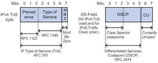
Table 10 IP precedence
|
IP precedence (decimal) |
IP precedence (binary) |
Description |
|
0 |
000 |
Routine |
|
1 |
001 |
priority |
|
2 |
010 |
immediate |
|
3 |
011 |
flash |
|
4 |
100 |
flash-override |
|
5 |
101 |
critical |
|
6 |
110 |
internet |
|
7 |
111 |
network |
Table 11 DSCP values
|
DSCP value (decimal) |
DSCP value (binary) |
Description |
|
46 |
101110 |
ef |
|
10 |
001010 |
af11 |
|
12 |
001100 |
af12 |
|
14 |
001110 |
af13 |
|
18 |
010010 |
af21 |
|
20 |
010100 |
af22 |
|
22 |
010110 |
af23 |
|
26 |
011010 |
af31 |
|
28 |
011100 |
af32 |
|
30 |
011110 |
af33 |
|
34 |
100010 |
af41 |
|
36 |
100100 |
af42 |
|
38 |
100110 |
af43 |
|
8 |
001000 |
cs1 |
|
16 |
010000 |
cs2 |
|
24 |
011000 |
cs3 |
|
32 |
100000 |
cs4 |
|
40 |
101000 |
cs5 |
|
48 |
110000 |
cs6 |
|
56 |
111000 |
cs7 |
|
0 |
000000 |
be (default) |
802.1p priority
802.1p priority lies in the Layer 2 header. It applies to occasions where Layer 3 header analysis is not needed and QoS must be assured at Layer 2.
As shown in Figure 31, the 4-byte 802.1Q tag header contains the 2-byte tag protocol identifier (TPID) and the 2-byte tag control information (TCI). The value of the TPID is 0x8100.
Figure 31 An Ethernet frame with an 802.1Q tag header
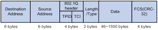
Figure 32 shows the format of the 802.1Q tag header. The Priority field in the 802.1Q tag header is called 802.1p priority, because its use is defined in IEEE 802.1p. Table 12 shows the values for 802.1p priority.
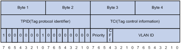
Table 12 Description on 802.1p priority
|
802.1p priority (decimal) |
802.1p priority (binary) |
Description |
|
0 |
000 |
best-effort |
|
1 |
001 |
background |
|
2 |
010 |
spare |
|
3 |
011 |
excellent-effort |
|
4 |
100 |
controlled-load |
|
5 |
101 |
video |
|
6 |
110 |
voice |
|
7 |
111 |
network-management |
EXP values
As shown in Figure 33, the EXP field is 3-bit long and is in the range of 0 to 7. The EXP field is in MPLS labels for MPLS QoS purposes.
Figure 33 MPLS label structure

Configuring MPLS QoS
Overview
MPLS uses 3 bits, called EXP bits, to carry class-of-service information to provide support for DiffServ. MPLS QoS identifies different traffic flows with different EXP bits and implements differentiated services. MPLS QoS can guarantee low delay and low packet loss ratio for critical service traffic, such as voice and video traffic. For more information about MPLS, see MPLS Configuration Guide.
MPLS QoS supports CAR and priority marking. MPLS QoS provides the following functions:
· Classify traffic on the PE and apply differentiated QoS strategies for different traffic classes. For example, MPLS QoS can organize packets with EXP value 1 into a class and packets with EXP value 2 into another class. Then it performs traffic policing and priority marking for each class of packets.
· When a PE labels a packet, it maps the IP precedence to the EXP field of the label. In this way, the class information carried in the IP header is carried in the label.
The EXP field in an MPLS label is processed according to the following rules:
· The device re-sets the EXP field of only the topmost label.
· During label encapsulation, the ToS field of the IP packet is directly changed into the EXP field of the MPLS label.
· The EXP field remains unchanged when label swapping is performed.
· During a label push operation, the EXP field of the newly pushed outer label inherits the EXP field of the inner label.
· After a label pop operation for a packet, the following rules apply:
? If the packet is still an MPLS packet, the EXP field of the popped label is not copied to the inner label.
? If the packet is an IP packet, the EXP field of the popped label is not copied to the ToS field of the IP packet.
Configuration prerequisites
Before configuring MPLS QoS, complete basic MPLS configuration. For more information about basic MPLS configurations, see MPLS Configuration Guide.
Configuring MPLS CAR
A CAR policy for traffic entering an MPLS network performs the following operations:
· Limits the transmission rate to avoid network congestion.
· Marks priority for the traffic.
For more information about traffic policing, see "Configuring traffic policing, GTS, and rate limit."
To configure MPLS CAR:
|
Step |
Command |
Remarks |
|
1. Enter system view. |
system-view |
N/A |
|
2. Enter interface view. |
interface interface-type interface-number |
N/A |
|
3. Configure an MPLS CAR policy for the interface. |
qos car { inbound | outbound } { any | acl [ ipv6 ] acl-number | carl carl-index } cir committed-information-rate [ cbs committed-burst-size [ ebs excess-burst-size ] ] [ green action | red action | yellow action ] * qos car { inbound | outbound } { any | acl [ ipv6 ] acl-number | carl carl-index } cir committed-information-rate [ cbs committed-burst-size ] pir peak-information-rate [ ebs excess-burst-size ] [ green action | red action | yellow action ] * |
By default, no CAR policy is configured for an interface. The action argument for MPLS can be either of the following options: · remark-mpls-exp-continue new-exp: Sets the EXP value to new-exp and continues to process the packet using the next CAR policy. The new-exp is in the range of 0 to 7. · remark-mpls-exp-pass new-exp: Sets the EXP value to new-exp and permits the packet to pass through. The new-exp is in the range of 0 to 7. |
Configuring MPLS priority marking
In an MPLS network, you can adjust the priority of an MPLS traffic flow by marking its EXP value. For more information about priority marking, see "Configuring priority marking."
To configure the MPLS priority marking action for an MPLS traffic class:
|
Step |
Command |
Remarks |
|
1. Enter system view. |
system-view |
N/A |
|
2. Create a traffic class and enter traffic class view. |
traffic classifier classifier-name [ operator { and | or } ] |
By default, no traffic classes exist. |
|
3. Configure match criteria for the traffic class. |
if-match [ not ] mpls-exp exp-value&<1-8> |
By default, no match criteria are configured. The match criteria apply only to MPLS packets. |
|
4. Return to system view. |
quit |
N/A |
|
5. Create a traffic behavior and enter traffic behavior view. |
traffic behavior behavior-name |
By default, no traffic behaviors exist. |
|
6. Configure an EXP marking action in the traffic behavior. |
remark mpls-exp exp-value |
By default, no EXP marking action is configured. |
|
7. Return to system view. |
quit |
N/A |
|
8. Create a QoS policy and enter QoS policy view. |
qos policy policy-name |
By default, no QoS policies exist. |
|
9. Associate the traffic class with the traffic behavior in the QoS policy. |
classifier classifier-name behavior behavior-name |
By default, no traffic behavior is associated with a traffic class. |
|
10. Return to system view. |
quit |
N/A |
|
11. Apply the QoS policy. |
You can apply a QoS policy to an interface or a control plane. For more information, see "Configuring a QoS policy." |
Use one of the destinations as needed. By default, no QoS policy is applied. |
MPLS QoS configuration example
Network requirements
As shown in Figure 34, perform the following tasks to provide differentiated QoS services for flows with different precedence values in VPN 1:
1. Configure MPLS VPN on CE 1, PE 1, P, PE 2, and CE 2 as follows:
? Run OSPF between PE 1 and P, and between PE 2 and P.
? Establish an MP-EBGP neighborship between PEs and CEs.
? Establish an MP-IBGP neighborship between PEs and PEs.
2. Configure MPLS QoS on PE 1 and P as follows:
? On PE 1, configure a QoS policy on GigabitEthernet 1/0/2 to set the EXP values for MPLS packets according to their DSCP values.
? On the P device, classify traffic on the basis of the EXP field, and configure flow-based CBQ as follows:
- Guarantee 10% of the bandwidth for traffic with an EXP value of 1.
- Guarantee 20% of the bandwidth for traffic with an EXP value of 2.
- Guarantee 30% of the bandwidth for traffic with an EXP value of 3.
- Guarantee a low delay and 40% of the bandwidth for traffic with an EXP value of 4.
For information about the MPLS configuration, see MPLS Configuration Guide. This section introduces only the MPLS QoS configuration.
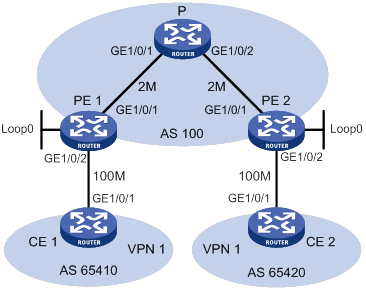
Table 13 Interfaces and IP address assignment
|
Device |
Interface |
IP address |
Device |
Interface |
IP address |
|
CE 1 |
CE 2 |
||||
|
PE 1 |
PE 2 |
||||
|
P |
|
|
|
||
|
|
|
|
Configuration procedure
1. Configure PE 1:
# Configure four classes to match MPLS packets with DSCP values AF11, AF21, AF31, and EF in the same VPN.
[PE1] traffic classifier af11
[PE1-classifier-af11] if-match dscp af11
[PE1-classifier-af11] quit
[PE1] traffic classifier af21
[PE1-classifier-af21] if-match dscp af21
[PE1-classifier-af21] quit
[PE1] traffic classifier af31
[PE1-classifier-af31] if-match dscp af31
[PE1-classifier-af31] quit
[PE1] traffic classifier efclass
[PE1-classifier-efclass] if-match dscp ef
[PE1-classifier-efclass] quit
# Configure four traffic behaviors to set the EXP values to 1, 2, 3, and 4 for MPLS packets.
[PE1-behavior-exp1] remark mpls-exp 1
[PE1-behavior-exp1] quit
[PE1] traffic behavior exp2
[PE1-behavior-exp2] remark mpls-exp 2
[PE1-behavior-exp2] quit
[PE1] traffic behavior exp3
[PE1-behavior-exp3] remark mpls-exp 3
[PE1-behavior-exp3] quit
[PE1] traffic behavior exp4
[PE1-behavior-exp4] remark mpls-exp 4
[PE1-behavior-exp4] quit
# Create QoS policy REMARK, and associate the behaviors with the classes in the QoS policy to mark different classes of packets with different EXP values.
[PE1-qospolicy-REMARK] classifier af11 behavior exp1
[PE1-qospolicy-REMARK] classifier af21 behavior exp2
[PE1-qospolicy-REMARK] classifier af31 behavior exp3
[PE1-qospolicy-REMARK] classifier efclass behavior exp4
[PE1-qospolicy-REMARK] quit
# Apply QoS policy REMARK to the incoming traffic of interface GigabitEthernet 1/0/2 of PE 1 in the MPLS network.
[PE1] interface gigabitethernet 1/0/2
[PE1-GigabitEthernet1/0/2] qos apply policy REMARK inbound
[PE1-GigabitEthernet1/0/2] quit
2. Configure device P:
# Configure four classes to match MPLS packets with EXP values 1, 2, 3 and 4.
[P] traffic classifier EXP1
[P-classifier-EXP1] if-match mpls-exp 1
[P-classifier-EXP1] quit
[P] traffic classifier EXP2
[P-classifier-EXP2] if-match mpls-exp 2
[P-classifier-EXP2] quit
[P] traffic classifier EXP3
[P-classifier-EXP3] if-match mpls-exp 3
[P-classifier-EXP3] quit
[P] traffic classifier EXP4
[P-classifier-EXP4] if-match mpls-exp 4
[P-classifier-EXP4] quit
# Create four traffic behaviors, and configure AF or EF actions for them.
[P-behavior-AF11] queue af bandwidth pct 10
[P-behavior-AF11] quit
[P] traffic behavior AF21
[P-behavior-AF21] queue af bandwidth pct 20
[P-behavior-AF21] quit
[P] traffic behavior AF31
[P-behavior-AF31] queue af bandwidth pct 30
[P-behavior-AF31] quit
[P] traffic behavior EF
[P-behavior-EF] queue ef bandwidth pct 40
[P-behavior-EF] quit
# Create QoS policy QUEUE, and associate the behaviors with the classes.
[P-qospolicy-QUEUE] classifier EXP1 behavior AF11
[P-qospolicy-QUEUE] classifier EXP2 behavior AF21
[P-qospolicy-QUEUE] classifier EXP3 behavior AF31
[P-qospolicy-QUEUE] classifier EXP4 behavior EF
[P-qospolicy-QUEUE] quit
# Apply QoS policy QUEUE to the outgoing traffic of GigabitEthernet 1/0/2.
[P] interface gigabitethernet 1/0/2
[P-GigabitEthernet1/0/2] qos apply policy QUEUE outbound
Verifying the configuration
# When congestion occurs in VPN 1, verify that:
· The bandwidth proportion between flows with the DSCP values af11, af21, af31, and ef is 1:2:3:4.
· The delay for the flow with DSCP value ef is smaller than the other traffic flows.
(Details not shown.)
Configuring FR QoS
Overview
On an FR interface, you can use generic QoS services to perform traffic shaping, traffic policing, congestion management, and congestion avoidance. You can also use FR-specific QoS mechanisms, including FR traffic shaping (FRTS), FR traffic policing (FRTP), FR congestion management, FR discard eligibility (DE) rule list, and FR queuing management.
FR QoS works on a per-PVC basis and is more flexible than generic QoS. For more information about Frame Relay, see Layer 2—WAN Configuration Guide.
Figure 35 FR QoS implementation
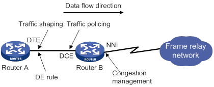
FR QoS parameters
FR QoS uses the following parameters:
· CIR ALLOW—Average transmission rate guaranteed on a PVC when no congestion occurs.
· CIR—Minimum transmission rate guaranteed on a PVC even if congestion occurs in the network.
· CBS—Size of traffic that a PVC is committed to transmitting within the interval of Tc when congestion occurs in the network.
· EBS—Maximum size of traffic that can exceed CBS on a PVC within the interval of Tc. When congestion occurs in the network, the traffic of the EBS size is dropped first. Transmitting traffic of the EBS size is not guaranteed by the FR network.
FRTS
Functionality
FRTS limits the outgoing traffic rate and smoothes bursts for PVCs. Then, PVCs can transmit traffic at a constant rate. FRTS applies to the outgoing interface of a switch. You can use FRTS to remove the bottleneck created when the input rate of a device is slower than the output rate of the sending device.
As shown in Figure 36:
· Router B transmits packets to Router A at 128 kbps.
· The maximum interface rate of Router A is only 64 kbps.
The disparity in traffic rate creates a bottleneck on the interface that connects Router A to the FR network.
To avoid packet loss, you can configure FRTS with the CIR ALLOW 64 kbps and the CIR 32 kbps on the outgoing interface Serial 2/1/1 of Router B. Then, the interface can transmit packets constantly at 64 kbps when no congestion occurs. Even if congestion occurs in the network, Router B can still transmit packets at the rate of 32 kbps.

FRTS uses the parameters CIR ALLOW, CIR, CBS, and EBS for traffic shaping. FR PVCs can transmit packets at the rate of CIR ALLOW when no congestion occurs. In the case of bursty packets, FRTS allows an FR PVC to transmit packets at a rate exceeding the CIR ALLOW.
When congestion occurs, the DCE sends FR packets with the BECN bit set to 1 to the DTE. Then, the DTE reduces its transmission rate from CIR ALLOW to CIR. If the DTE does not receive an FR packet with the BECN bit set to 1 within 125 milliseconds, it increases its transmission rate back to CIR ALLOW.
How FRTS works
FRTS is implemented by using token buckets. The meanings of the related parameters in the protocol are modified as required by the actual algorithm and principles. Figure 37 shows how a token bucket works.
Figure 37 How a token bucket works
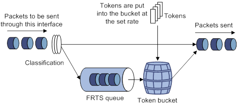
In the token bucket method, packets requiring traffic control are processed in the token bucket as follows before transmission:
· If the token bucket has enough tokens (in bits) for sending these packets, the packets are allowed to pass.
· If the token bucket does not have enough tokens for sending these packets, these packets are put into the FR class queue.
· Once the token bucket has enough tokens, the packets are taken out of the FR class queue for transmission.
In this way, you can control the rate of a class of packets. .
The FR protocol-provisioned parameters correspond to the FRTS parameters as follows:
· The sum of CBS and EBS equals the token bucket size.
· The CIR ALLOW defines the number of tokens put into the token bucket per second.
For efficiency, the FRTS introduces the concept of dynamic Tc (Tc=packet size/CIR ALLOW). The Tc can be dynamic adjusted depending on the transmitted packet size. The device allocates the required tokens to the current packets waiting for transmission within the latest Tc regardless of the packet size (smaller than 1500 bytes).
For example, send an 800-byte packet. If the CIR ALLOW of 64000 kbps, it takes Tc=6400/64000=0.1 second (100 ms) to put the required tokens into the token bucket. The packet is transmitted successfully if 6400 bits of tokens are put into the token bucket within 100 ms.
FRTP
FRTP monitors the traffic entering the network from each PVC and limits the traffic to specified traffic parameters. If the traffic on a PVC exceeds the user-defined threshold, the device takes action to conserve network resources.
Figure 38 FR traffic policing implementation
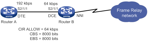
As shown in Figure 38, Router A on the user side transmits packets at the rate of 192 kbps to Router B on the switching side. To provide Router A with only 64 kbps of bandwidth, the FR traffic policing settings in the figure are used on the DCE side of Router B.
· When the traffic from Router A is smaller than the CBS, Router B forwards the packets without any other processing.
· When the traffic from Router A is larger than the CBS and smaller than EBS + CBS, the packets can be transmitted. However, for those packets of the traffic that exceeds the CBS, Router B sets the DE bit in the FR header to 1.
· When the traffic from Router A is larger than CBS + EBS, Router B performs the following operations:
? Transmits the traffic that is equal to CBS + EBS.
? Sets the DE bit in the FR header to 1 for the traffic that exceeds the CBS.
? Drops the traffic that exceeds CBS + EBS.
FR queuing
FR queuing includes PVC queuing and interface queuing. Figure 39 shows the relationship between PVC queuing and interface queuing.
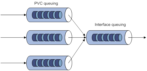
The device schedules packets by using PVC queuing before the device schedules them by using interface queuing.
PVC queuing takes effect only when FRTS is enabled.
FR interface queuing
The following queuing mechanisms are available on FR interfaces:
· FIFO.
· PVC PQ.
For more information about FIFO and PQ, see "Configuring congestion management."
PVC PQ has four queues (top, middle, normal, and bottom queues, in the descending priority order). The packets from one PVC are assigned to the same priority queue. PVC PQ dequeues and sends packets in the high-priority queue and then packets in the low-priority queue. The priority queue for a PVC is configured in the FR class associated with the PVC.
FR PVC queuing
After FRTS is enabled on an FR interface, each PVC on the interface has a queuing mechanism.
The following queuing mechanisms are available on FR PVCs:
· CBQ.
· CQ.
· FIFO.
· PQ.
· RTPQ.
· WFQ.
Only RTPQ can coexist with another queuing mechanism on a PVC. For information about queuing mechanisms, see "Configuring congestion management."
FR DE rule list
In an FR network, packets with the DE bits set to 1 are dropped first when congestion occurs. DE rule lists are applied on the FR PVCs of a device. An DE rule list can contain multiple DE rules. If a packet transmitted over the PVC matches the rules in the DE rule list, its DE bit is set to 1.
Feature and hardware compatibility
The following matrix shows the feature and hardware compatibility:
|
Hardware |
FR QoS compatibility |
|
MSR810/810-W/810-W-DB/810-LM/810-W-LM/810-10-PoE/810-LM-HK/810-W-LM-HK |
No |
|
MSR810-LMS/810-LUS |
Yes |
|
MSR2600-6-X1/2600-10-X1 |
Yes |
|
MSR 2630 |
Yes |
|
MSR3600-28/3600-51 |
Yes |
|
MSR3600-28-SI/3600-51-SI |
Yes |
|
MSR3610-X1/3610-X1-DP/3610-X1-DC/3610-X1-DP-DC |
Yes |
|
MSR 3610/3620/3620-DP/3640/3660 |
Yes |
|
MSR5620/5660/5680 |
Yes |
|
Hardware |
FR QoS compatibility |
|
MSR810-LM-GL |
Yes |
|
MSR810-W-LM-GL |
Yes |
|
MSR830-6EI-GL |
Yes |
|
MSR830-10EI-GL |
Yes |
|
MSR830-6HI-GL |
Yes |
|
MSR830-10HI-GL |
Yes |
|
MSR2600-6-X1-GL |
Yes |
|
MSR3600-28-SI-GL |
Yes |
FR QoS configuration task list
|
Tasks at a glance |
|
(Required.) Creating and configuring an FR class |
|
(Optional.) Configuring FRTS |
|
(Optional.) Configuring FRTP |
|
(Optional.) Configuring FR queuing |
|
(Optional.) Configuring an FR DE rule list |
|
(Optional.) Configuring Frame Relay FRF.12 fragmentation for an FR class |
Creating and configuring an FR class
To provide QoS on a PVC, perform the following tasks:
1. Create an FR class.
2. Set QoS parameters in the FR class.
In FR class view, you can configure QoS parameters for QoS services such as FRTS, FR traffic policing, FR congestion management, and FR queuing. For more information about the parameter configurations, see "Configuring FRTS."
3. Associate the FR class with the PVC.
You can associate an FR class with PVCs indirectly by associating it with FR interfaces or directly by associating it with these PVCs.
· The FR class associated with an FR interface takes effect on all PVCs on the interface.
· The FR class associated with a PVC takes effect only on the PVC.
A QoS-capable FR PVC selects an FR class in the following order:
4. The FR class associated with the PVC.
5. The FR class associated with the FR interface of the PVC.
To create and configure an FR class:
|
Step |
Command |
Remarks |
|
1. Enter system view. |
system-view |
N/A |
|
2. Create an FR class and enter FR class view. |
fr class class-name |
By default, no FR classes exist. |
|
3. Return to system view. |
quit |
N/A |
|
4. Associate the FR class with an FR interface or PVC. |
·
Method 1: a. Enter FR interface (main interface or subinterface) view: b. Associate the FR class with the FR interface: ·
Method 2: c. Enter FR interface view: d. Enter FR PVC view: e. Associate the FR class with the PVC: |
Use either method or both methods. By default, an FR class is not associated with any FR interface or PVC. |
Configuring FRTS
Configuration restrictions and guidelines
When you configure FRTS, follow these restrictions and guidelines:
· FRTS applies to the outgoing FR packets. It is typically applied on DTEs.
· You can use the cbs, cbs, and cir allow commands to set both the inbound and outbound parameters for an FR class. However, only the outbound parameters take effect.
Configuration procedure
To configure FRTS:
|
Step |
Command |
Remarks |
|
1. Enter system view. |
system-view |
N/A |
|
2. Enter FR interface view. |
interface interface-type interface-number |
N/A |
|
3. Enable FRTS. |
fr traffic-shaping |
By default, FRTS is disabled. |
|
4. Return to system view. |
quit |
N/A |
|
5. Enter FR class view. |
fr class class-name |
N/A |
|
6. (Optional.) Set the CBS for the FR class. |
cbs [ inbound | outbound ] committed-burst-size |
The default setting is 56000 bits. |
|
7. (Optional.) Set the CIR for the FR class. |
cir committed-information-rate |
The default setting is 56000 bps. |
|
8. (Optional.) Set the CIR ALLOW for the FR class. |
cir allow [ inbound | outbound ] committed-information-rate |
The default setting is 56000 bps. |
|
9. (Optional.) Set the EBS for FR class. |
ebs [ inbound | outbound ] excess-burst-size |
The default setting is 0 bits. |
|
10. (Optional.) Enable FRTS adaptation. |
traffic-shaping adaptation { becn | interface-congestion number } |
By default, FRTS adaptation is disabled. |
|
11. (Optional.) Set the FRTS adaptation percentage. |
traffic-shaping adaptation percentage number |
The default setting is 25%. |
Configuring FRTP
Configuration restrictions and guidelines
When you configure FRTP, follow these restrictions and guidelines:
· FRTP is applied to the interfaces receiving FR packets and can only be applied to the DCE of an FR network.
· You can use the cbs, ebs, and cir allow commands to set both inbound and outbound parameters for an FR class. However, only inbound parameters take effect.
Configuration procedure
To configure FRTP:
|
Step |
Command |
Remarks |
|
1. Enter system view. |
system-view |
N/A |
|
2. Enter FR interface view. |
interface interface-type interface-number |
N/A |
|
3. Enable FRTP. |
fr traffic-policing |
By default, FRTP is disabled. |
|
4. Return to system view. |
quit |
N/A |
|
5. Enter FR class view. |
fr class class-name |
N/A |
|
6. (Optional.) Set the CBS for the FR class. |
cbs [ inbound | outbound ] committed-burst-size |
The default setting is 56000 bits. |
|
7. (Optional.) Set the CIR for the FR class. |
cir committed-information-rate |
The default setting is 56000 bps. |
|
8. (Optional.) Set CIR ALLOW for the FR class. |
cir allow [ inbound | outbound ] committed-information-rate |
The default setting is 56000 bps. |
|
9. (Optional.) Set the EBS for the FR class. |
ebs [ inbound | outbound ] excess-burst-size |
The default setting is 0 bits. |
Configuring FR queuing
Configuring PVC queuing as FIFO, PQ, CQ, WFQ, or RTPQ
|
Step |
Command |
Remarks |
|
1. Enter system view. |
system-view |
N/A |
|
2. Enter FR class view. |
fr class class-name |
N/A |
|
3. Configure a PVC queuing mechanism. |
·
Configure FIFO: ·
Configure PQ: ·
Configure CQ: ·
Configure WFQ: ·
Configure RTPQ: |
By default, FIFO is used, and the queue length is 75 packets. RTPQ can coexist with another queuing mechanism. However, any two queuing mechanisms other than RTPQ cannot coexist in an FR class. |
Configuring PVC queuing as CBQ
|
Step |
Command |
Remarks |
|
1. Enter system view. |
system-view |
N/A |
|
2. Create a traffic class and enter traffic class view. |
traffic classifier classifier-name [ operator { and | or } ] |
By default, no traffic classes exist. |
|
3. Configure a match criterion. |
if-match [ not ] match-criteria |
By default, no match criterion is configured. |
|
4. Return to system view. |
quit |
N/A |
|
5. Create a traffic behavior and enter traffic behavior view. |
traffic behavior behavior-name |
By default, no traffic behaviors exist. |
|
6. Configure a CBQ action. |
By default, no CBQ action is configured. |
|
|
7. Return to system view. |
quit |
N/A |
|
8. Create a QoS policy and enter QoS policy view. |
qos policy policy-name |
By default, no QoS policies exist. |
|
9. Associate the traffic class with the traffic behavior in the QoS policy. |
classifier classifier-name behavior behavior-name |
By default, a traffic class is not associated with a traffic behavior. |
|
10. Return to system view. |
quit |
N/A |
|
11. Enter FR class view. |
fr class class-name |
N/A |
|
12. Apply the QoS policy to the FR class. |
apply policy policy-name outbound |
By default, no QoS policy is applied to an FR class. |
Configuring interface queuing as PVC PQ
By default, an FR interface uses FIFO queuing. You can configure an FR interface to use PVC PQ.
To configure PVC PQ:
|
Step |
Command |
Remarks |
|
1. Enter system view. |
system-view |
N/A |
|
2. Enter FR interface view. |
interface interface-type interface-number |
N/A |
|
3. Enable PVC PQ for the FR interface. |
fr pvc-pq [ top-limit middle-limit normal-limit bottom-limit ] |
By default, an FR interface uses FIFO queuing. |
|
4. Return to system view. |
quit |
N/A |
|
5. Enter FR class view. |
fr class class-name |
N/A |
|
6. Specify a PVC PQ priority queue for the FR class. |
pvc-pq { bottom | middle | normal | top } |
By default, packets from an FR class are assigned to the normal queue. |
|
7. Return to system view. |
quit |
N/A |
|
8. Enter FR interface view. |
interface interface-type interface-number |
N/A |
|
9. Enter FR PVC view. |
fr dlci dlci-number |
N/A |
|
10. Associate the FR class with the PVC. |
fr-class class-name |
By default, an FR class is not associated with any FR PVC. |
Configuring an FR DE rule list
|
Step |
Command |
Remarks |
|
1. Enter system view. |
system-view |
N/A |
|
2. Configure a DE rule list. |
·
Create a DE rule list and add an
interface-based DE rule: ·
Create a DE rule list and add an IP protocol-based
DE rule: |
Use one of the commands. By default, no DE rule list exists. |
|
3. Enter FR interface view. |
interface interface-type interface-number |
N/A |
|
4. Apply the DE rule list to an FR PVC of the interface. |
fr de del list-number dlci dlci-number |
By default, no DE rule list is applied to an FR PVC. Up to 10 DE rule lists can be applied on a device. A DE rule list can be configured with up to 100 DE rules. |
Configuring Frame Relay FRF.12 fragmentation for an FR class
For Frame Relay FRF.12 fragmentation to take effect on PVCs, perform the following tasks after you configure Frame Relay FRF.12 fragmentation for an FR class:
· Associate the PVCs with the FR class or associate the interfaces where the PVCs reside with the FR class.
· Enable FRTS on the interfaces where the PVCs reside.
FRTS and FRF.12 fragmentation are mutually exclusive on an interface. For information about configuring FRF.12 fragmentation on an interface, see Layer 2—WAN Access Configuration Guide.
To configure Frame Relay FRF.12 fragmentation for an FR class:
|
Step |
Command |
Remarks |
|
1. Enter system view. |
system-view |
N/A |
|
2. Enter FR class view. |
fr class class-name |
N/A |
|
3. Enable Frame Relay FRF.12 fragmentation for the FR class. |
fragment enable |
By default, FRF.12 fragmentation is disabled for an FR class. |
|
4. (Optional.) Set the fragment size allowed for the FR class. |
fragment size |
The default setting is 45 bytes. |
|
5. Enter interface view. |
interface interface-type interface-number |
N/A |
|
6. Enable FRTS. |
fr traffic-shaping |
By default, FRTS is disabled on an interface. |
Displaying and maintaining FR QoS
Execute display commands in any view.
|
Task |
Command |
|
Display the associations between FR classes and interfaces (including subinterfaces and PVCs). |
display fr class-map [ fr-class class-name | interface interface-type interface-number ] |
|
Display the configuration and statistics for FR QoS. |
display fr pvc [ interface interface-type interface-number ] [ dlci dlci-number ] |
FRTS configuration example
Network requirements
As shown in Figure 40:
· The maximum rate of Serial 2/1/1 on Router A is 64 kbps.
· Router B sends packets to Router A at 128 kbps.
Configure FRTS on the outgoing interface Serial 2/1/1 of Router B to limit its transmission rate to an average of 64 kbps.
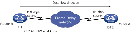
Configuration procedure
# Create FR class 64k and configure its FRTS parameters.
[RouterB] fr class 64k
[RouterB-fr-class-64k] cir allow 64000
[RouterB-fr-class-64k] cir 32000
[RouterB-fr-class-64k] cbs 64000
[RouterB-fr-class-64k] ebs 32000
[RouterB-fr-class-64k] traffic-shaping adaptation becn
[RouterB-fr-class-64k] traffic-shaping adaptation percentage 20
[RouterB-fr-class-64k] quit
# Enable FR encapsulation and FRTS on interface Serial 2/1/1.
[RouterB] interface serial 2/1/1
[RouterB-Serial2/1/1] link-protocol fr
[RouterB-Serial2/1/1] fr traffic-shaping
# Create an FR PVC and associate FR class 64k with the FR PVC.
[RouterB-Serial2/1/1] fr dlci 16
[RouterB-Serial2/1/1-fr-dlci-16] fr-class 64k
Verifying the configuration
# Display the FR QoS configuration and statistics for the PVC with DLCI 16.
[RouterB-Serial2/1/1-fr-dlci-16] display fr pvc dlci 16
PVC information for interface Serial2/1/1 (DTE, physically up)
DLCI: 16 Type: Static Interface: Serial2/1/1
Encapsulation: IETF
Creation time: 2014/02/19 01:38:00 Status: Active
Input: 4 packets, 120 bytes, 0 dropped
Output: 4 packets, 120 bytes, 0 dropped
Traffic shaping: Active
CIR allow: 64000 bps CIR: 32000 bps
CBS: 64000 bits EBS: 32000 bits
Current CIR: 64000 bps
Output: 0 packets, 0 bytes, 0 dropped packets
Delayed: 0 packets, 0 bytes
Output queue: (Urgent queuing: Size/Length/Discards) 0/100/0
Output queue: (Protocol queuing: Size/Length/Discards) 0/500/0
Output queue: (FIFO queuing: Size/Length/Discards) 0/75/0
The output shows that traffic shaping is enabled and the CIR ALLOW is 64 kbps.
Configuring time ranges
You can implement a service based on the time of the day by applying a time range to it. A time-based service takes effect only in time periods specified by the time range. For example, you can implement time-based ACL rules by applying a time range to them. If a time range does not exist, the service based on the time range does not take effect.
The following basic types of time ranges are available:
· Periodic time range—Recurs periodically on a day or days of the week.
· Absolute time range—Represents only a period of time and does not recur.
A time range is uniquely identified by the time range name. You can create a maximum of 1024 time ranges, each with a maximum of 32 periodic statements and 12 absolute statements. The active period of a time range is calculated as follows:
1. Combining all periodic statements.
2. Combining all absolute statements.
3. Taking the intersection of the two statement sets as the active period of the time range.
Configuration procedure
|
Step |
Command |
Remarks |
|
1. Enter system view. |
system-view |
N/A |
|
2. Create or edit a time range. |
time-range time-range-name { start-time to end-time days [ from time1 date1 ] [ to time2 date2 ] | from time1 date1 [ to time2 date2 ] | to time2 date2 } |
By default, no time ranges exist. |
Displaying and maintaining time ranges
Execute the display command in any view.
|
Task |
Command |
|
Display time range configuration and status. |
display time-range { time-range-name | all } |
Time range configuration example
Network requirements
As shown in Figure 41, configure an ACL on the device to allow Host A to access the server only during 8:00 and 18:00 on working days from June 2015 to the end of the year.
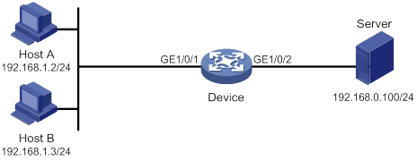
Configuration procedure
# Create a periodic time range during 8:00 and 18:00 on working days from June 2015 to the end of the year.
<Device> system-view
[Device] time-range work 8:0 to 18:0 working-day from 0:0 6/1/2015 to 24:00 12/31/2015
# Create an IPv4 basic ACL numbered 2001, and configure a rule in the ACL to permit packets only from 192.168.1.2/32 during the time range work.
[Device] acl basic 2001
[Device-acl-ipv4-basic-2001] rule permit source 192.168.1.2 0 time-range work
[Device-acl-ipv4-basic-2001] rule deny source any time-range work
[Device-acl-ipv4-basic-2001] quit
# Apply IPv4 basic ACL 2001 to filter outgoing packets on GigabitEthernet 1/0/2.
[Device] interface gigabitEthernet 1/0/2
[Device-GigabitEthernet1/0/2] packet-filter 2001 outbound
[Device-GigabitEthernet1/0/2] quit
Verifying the configuration
# Verify that the time range work is active on the device.
[Device] display time-range all
Current time is 13:58:35 6/29/2015 Friday
Time-range : work (Active)
08:00 to 18:00 working-day
from 00:00 6/1/2015 to 00:00 1/1/2016
ACL configuration examples,12
Appendix A Acronym,107
Appendix B Default priority maps,108
Appendix C Introduction to packet precedences,109
Applying the QoS policy,24
Changing the port priority of an interface,33
Command and hardware compatibility,22
Command and hardware compatibility,42
Command and hardware compatibility,58
Command and hardware compatibility,20
Command and hardware compatibility,3
Configuration example,81
Configuration example,84
Configuration example,88
Configuration prerequisites,112
Configuration procedure,129
Configuration procedure,87
Configuration procedure,81
Configuration procedure,83
Configuration procedure diagram,21
Configuration restrictions and guidelines,3
Configuration task list,4
Configuring a basic ACL,4
Configuring a Layer 2 ACL,8
Configuring a port to trust packet priority for priority mapping,32
Configuring a priority map,32
Configuring an advanced ACL,5
Configuring an FR DE rule list,125
Configuring CBQ,65
Configuring CQ,62
Configuring FR queuing,124
Configuring Frame Relay FRF.12 fragmentation for an FR class,126
Configuring FRTP,123
Configuring FRTS,122
Configuring GTS,46
Configuring MPLS CAR,112
Configuring MPLS priority marking,113
Configuring packet filtering with ACLs,9
Configuring PQ,60
Configuring QoS tokens,74
Configuring RTPQ,73
Configuring the rate limit,48
Configuring the route receiver,91
Configuring the route sender,91
Configuring traffic policing,43
Configuring WFQ,64
Configuring WRED on an interface,79
Copying an ACL,9
Creating and configuring an FR class,121
Defining a QoS policy,22
Defining a traffic behavior,22
Defining a traffic class,22
Displaying and maintaining ACLs,11
Displaying and maintaining congestion management,75
Displaying and maintaining FR QoS,126
Displaying and maintaining priority mapping,34
Displaying and maintaining QoS policies,28
Displaying and maintaining time ranges,129
Displaying and maintaining traffic policing, GTS, and rate limit,49
Displaying and maintaining WRED,80
Enabling ACL acceleration,11
Enabling packet information pre-extraction,73
Feature and hardware compatibility,87
Feature and hardware compatibility,120
FR QoS configuration task list,121
FRTS configuration example,127
MPLS QoS configuration example,114
MQC approach,21
Non-MQC approach,21
Overview,31
Overview,1
Overview,38
Overview,117
Overview,112
Overview,90
Overview,77
Overview,52
Priority mapping configuration examples,34
Priority mapping configuration tasks,31
QoS service models,18
QoS techniques overview,18
QPPB configuration examples,92
QPPB configuration task list,90
QPPB fundamentals,90
Setting the FIFO queue size,59
Setting the QoS policy-based traffic rate statistics collection period for an interface,28
Time range configuration example,129
Traffic policing, GTS, and rate limit configuration examples,49
