- Table of Contents
- Related Documents
-
| Title | Size | Download |
|---|---|---|
| 01-Text | 4.59 MB |
Contents
Information transmission techniques
Multicast benefits and applications
Multicast packet forwarding mechanism
Feature and hardware compatibility
Command and hardware compatibility
IGMP snooping configuration task list
Configuring basic IGMP snooping features
Specifying an IGMP snooping version
Setting the maximum number of IGMP snooping forwarding entries
Setting the IGMP last member query interval
Configuring IGMP snooping port features
Setting aging timers for dynamic ports
Configuring a port as a simulated member host
Enabling fast-leave processing
Disabling a port from becoming a dynamic router port
Configuring the IGMP snooping querier
Enabling the IGMP snooping querier
Configuring parameters for IGMP general queries and responses
Configuring parameters for IGMP messages
Configuring source IP addresses for IGMP messages
Setting the 802.1p priority for IGMP messages
Configuring IGMP snooping policies
Configuring a multicast group policy
Enabling multicast source port filtering
Enabling dropping unknown multicast data
Enabling IGMP report suppression
Setting the maximum number of multicast groups on a port
Enabling the multicast group replacement feature
Displaying and maintaining IGMP snooping
IGMP snooping configuration examples
Group policy and simulated joining configuration example
Static port configuration example
IGMP snooping querier configuration example
Layer 2 multicast forwarding cannot function
Multicast group policy does not work
Configuring multicast routing and forwarding
Multicast forwarding across unicast subnets
Feature and hardware compatibility
Command and hardware compatibility
Multicast routing and forwarding configuration task list
Configuring multicast routing and forwarding
Configuring static multicast routes
Specifying the longest prefix match principle
Configuring multicast load splitting
Configuring a multicast forwarding boundary
Configuring static multicast MAC address entries
Displaying and maintaining multicast routing and forwarding
Multicast routing and forwarding configuration examples
Multicast forwarding over a GRE tunnel
Multicast forwarding over ADVPN tunnels
Troubleshooting multicast routing and forwarding
Static multicast route failure
Feature and hardware compatibility
Configuring basic IGMP features
Configuring a static group member
Configuring a multicast group policy
Configuring IGMP query and response parameters
Enabling fast-leave processing
Enabling multicast forwarding on a non-querier interface
Configuring multicast load splitting on an IGMP proxy
Displaying and maintaining IGMP
Basic IGMP features configuration examples
IGMP SSM mapping configuration example
IGMP proxying configuration example
No membership information on the receiver-side router
Inconsistent membership information on the routers on the same subnet
Administrative scoping overview
Relationship among PIM protocols
Feature and hardware compatibility
PIM-DM configuration task list
Enabling the state refresh feature
Configuring state refresh parameters
Configuring PIM-DM graft retry timer
PIM-SM configuration task list
Configuring multicast source registration
Configuring the switchover to SPT
BIDIR-PIM configuration task list
PIM-SSM configuration task list
Configuring the SSM group range
Configuring common PIM features
Configuring a multicast source policy
Configuring a PIM hello policy
Configuring PIM hello message options
Setting the maximum size of each join or prune message
Enabling SNMP notifications for PIM
Enabling NBMA mode for ADVPN tunnel interfaces
Displaying and maintaining PIM
PIM-SM non-scoped zone configuration example
PIM-SM admin-scoped zone configuration example
BIDIR-PIM configuration example
A multicast distribution tree cannot be correctly built
Multicast data is abnormally terminated on an intermediate router
An RP cannot join an SPT in PIM-SM
An RPT cannot be built or multicast source registration fails in PIM-SM
Feature and hardware compatibility
Configuring basic MSDP features
Configuring an MSDP peering connection
Configuring a description for an MSDP peer
Configuring an MSDP mesh group
Controlling MSDP peering connections
Configuring SA message-related parameters
Enabling multicast data encapsulation in SA messages
Configuring the originating RP of SA messages
Configuring SA request messages
Configuring SA message policies
Configuring the SA cache mechanism
Displaying and maintaining MSDP
PIM-SM inter-domain multicast configuration
Inter-AS multicast configuration by leveraging static RPF peers
SA message filtering configuration
MSDP peers stay in disabled state
No SA entries exist in the router's SA message cache
No exchange of locally registered (S, G) entries between RPs
Feature and hardware compatibility
Multicast VPN configuration task list
Enabling IP multicast routing for a VPN instance
Creating an MD for a VPN instance
Specifying the MD source interface
Configuring MDT switchover parameters
Configuring the RPF vector feature
Enabling data-group reuse logging
Configuring BGP MDT peers or peer groups
Configuring a BGP MDT route reflector
Displaying and maintaining multicast VPN
Multicast VPN configuration examples
Intra-AS MD VPN configuration example
Intra-AS M6VPE configuration example
MD VPN inter-AS option C configuration example
MD VPN inter-AS option B configuration example
A default-MDT cannot be established
Feature and hardware compatibility
Command and hardware compatibility
MLD snooping configuration task list
Configuring basic MLD snooping features
Specifying an MLD snooping version
Setting the maximum number of MLD snooping forwarding entries
Setting the MLD last listener query interval
Configuring MLD snooping port features
Setting aging timers for dynamic ports
Configuring a port as a simulated member host
Enabling fast-leave processing
Disabling a port from becoming a dynamic router port
Configuring the MLD snooping querier
Enabling the MLD snooping querier
Configuring parameters for MLD general queries and responses
Configuring parameters for MLD messages
Configuring source IPv6 addresses for MLD messages
Setting the 802.1p priority for MLD messages
Configuring MLD snooping policies
Configuring an IPv6 multicast group policy
Enabling IPv6 multicast source port filtering
Enabling dropping unknown IPv6 multicast data
Enabling MLD report suppression
Setting the maximum number of IPv6 multicast groups on a port
Enabling the IPv6 multicast group replacement feature
Displaying and maintaining MLD snooping
MLD snooping configuration examples
IPv6 group policy and simulated joining configuration example
Static port configuration example
MLD snooping querier configuration example
Layer 2 multicast forwarding cannot function
IPv6 multicast group policy does not work
Configuring IPv6 multicast routing and forwarding
IPv6 multicast forwarding across IPv6 unicast subnets
Feature and hardware compatibility
Command and hardware compatibility
IPv6 multicast routing and forwarding configuration task list
Enabling IPv6 multicast routing
Configuring IPv6 multicast routing and forwarding
Specifying the longest prefix match principle
Configuring IPv6 multicast load splitting
Configuring an IPv6 multicast forwarding boundary
Configuring static IPv6 multicast MAC address entries
Displaying and maintaining IPv6 multicast routing and forwarding
IPv6 multicast routing and forwarding configuration examples
IPv6 multicast forwarding over a GRE tunnel
IPv6 multicast forwarding over ADVPN tunnel interfaces
Feature and hardware compatibility
Configuring basic MLD features
Configuring a static group member
Configuring an IPv6 multicast group policy
Configuring MLD query and response parameters
Enabling fast-leave processing
Enabling IPv6 multicast forwarding on a non-querier interface
Configuring IPv6 multicast load splitting on an MLD proxy
Displaying and maintaining MLD
Basic MLD features configuration examples
MLD SSM mapping configuration example
MLD proxying configuration example
No member information exists on the receiver-side router
Inconsistent membership information on the routers on the same subnet
IPv6 administrative scoping overview
Relationship among IPv6 PIM protocols
Feature and hardware compatibility
IPv6 PIM-DM configuration task list
Enabling the state refresh feature
Configuring state refresh parameters
Configuring IPv6 PIM-DM graft retry timer
IPv6 PIM-SM configuration task list
Configuring IPv6 multicast source registration
Configuring the switchover to SPT
IPv6 BIDIR-PIM configuration task list
IPv6 PIM-SSM configuration task list
Configuring the IPv6 SSM group range
Configuring common IPv6 PIM features
Configuring an IPv6 multicast source policy
Configuring an IPv6 PIM hello policy
Configuring IPv6 PIM hello message options
Configuring common IPv6 PIM timers
Setting the maximum size of each join or prune message
Enabling IPv6 PIM passive mode
Enabling SNMP notifications for IPv6 PIM
Enabling NBMA mode for IPv6 ADVPN tunnel interfaces
Displaying and maintaining IPv6 PIM
IPv6 PIM configuration examples
IPv6 PIM-DM configuration example
IPv6 PIM-SM non-scoped zone configuration example
IPv6 PIM-SM admin-scoped zone configuration example
IPv6 BIDIR-PIM configuration example
IPv6 PIM-SSM configuration example
A multicast distribution tree cannot be correctly built
IPv6 multicast data is abnormally terminated on an intermediate router
An RP cannot join an SPT in IPv6 PIM-SM
An RPT cannot be built or IPv6 multicast source registration fails in IPv6 PIM-SM
Multicast overview
Introduction to multicast
As a technique that coexists with unicast and broadcast, the multicast technique effectively addresses the issue of point-to-multipoint data transmission. By enabling high-efficiency point-to-multipoint data transmission over a network, multicast greatly saves network bandwidth and reduces network load.
By using multicast technology, a network operator can easily provide bandwidth-critical and time-critical information services. These services include live webcasting, Web TV, distance learning, telemedicine, Web radio, and real-time video conferencing.
Information transmission techniques
The information transmission techniques include unicast, broadcast, and multicast.
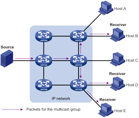
Unicast
In unicast transmission, the information source must send a separate copy of information to each host that needs the information.
In Figure 1, Host B, Host D, and Host E need the information. A separate transmission channel must be established from the information source to each of these hosts.
In unicast transmission, the traffic transmitted over the network is proportional to the number of hosts that need the information. If a large number of hosts need the information, the information source must send a separate copy of the same information to each of these hosts. Sending many copies can place a tremendous pressure on the information source and the network bandwidth.
Unicast is not suitable for batch transmission of information.
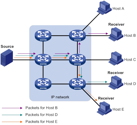
Broadcast
In broadcast transmission, the information source sends information to all hosts on the subnet, even if some hosts do not need the information.
Figure 2 Broadcast transmission
In Figure 2, only Host B, Host D, and Host E need the information. If the information is broadcast to the subnet, Host A and Host C also receive it. In addition to information security issues, broadcasting to hosts that do not need the information also causes traffic flooding on the same subnet.
Broadcast is disadvantageous in transmitting data to specific hosts. Moreover, broadcast transmission is a significant waste of network resources.
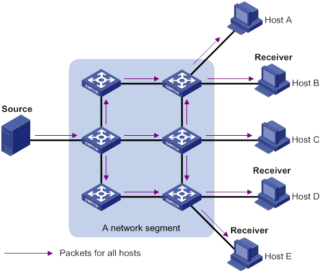
Multicast
Multicast provides point-to-multipoint data transmissions with the minimum network consumption. When some hosts on the network need multicast information, the information sender, or multicast source, sends only one copy of the information. Multicast distribution trees are built through multicast routing protocols, and the packets are replicated only on nodes where the trees branch.
Figure 3 Multicast transmission
In Figure 3, the multicast source sends only one copy of the information to a multicast group. Host B, Host D, and Host E, which are information receivers, must join the multicast group. The routers on the network duplicate and forward the information based on the distribution of the group members. Finally, the information is correctly delivered to Host B, Host D, and Host E.
To summarize, multicast has the following advantages:
· Advantages over unicast—Multicast data is replicated and distributed until it flows to the farthest-possible node from the source. The increase of receiver hosts will not remarkably increase the load of the source or the usage of network resources.
· Advantages over broadcast—Multicast data is sent only to the receivers that need it. This saves network bandwidth and enhances network security. In addition, multicast data is not confined to the same subnet.
Multicast features
· A multicast group is a multicast receiver set identified by an IP multicast address. Hosts must join a multicast group to become members of the multicast group before they receive the multicast data addressed to that multicast group. Typically, a multicast source does not need to join a multicast group.
· A multicast source is an information sender. It can send data to multiple multicast groups at the same time. Multiple multicast sources can send data to the same multicast group at the same time.
· The group memberships are dynamic. Hosts can join or leave multicast groups at any time. Multicast groups are not subject to geographic restrictions.
· Multicast routers or Layer 3 multicast devices are routers or Layer 3 switches that support Layer 3 multicast. They provide multicast routing and manage multicast group memberships on stub subnets with attached group members. A multicast router itself can be a multicast group member.
For a better understanding of the multicast concept, you can compare multicast transmission to the transmission of TV programs.
Table 1 Comparing TV program transmission and multicast transmission
|
TV program transmission |
Multicast transmission |
|
A TV station transmits a TV program through a channel. |
A multicast source sends multicast data to a multicast group. |
|
A user tunes the TV set to the channel. |
A receiver joins the multicast group. |
|
The user starts to watch the TV program transmitted by the TV station on the channel. |
The receiver starts to receive the multicast data sent by the source to the multicast group. |
|
The user turns off the TV set or tunes to another channel. |
The receiver leaves the multicast group or joins another group. |
Common notations in multicast
The following notations are commonly used in multicast transmission:
· (*, G)—Rendezvous point tree (RPT), or a multicast packet that any multicast source sends to multicast group G. The asterisk (*) represents any multicast source, and "G" represents a specific multicast group.
· (S, G)—Shortest path tree (SPT), or a multicast packet that multicast source "S" sends to multicast group "G." "S" represents a specific multicast source, and "G" represents a specific multicast group.
For more information about the concepts RPT and SPT, see "Configuring PIM" and "Configuring IPv6 PIM."
Multicast benefits and applications
Multicast benefits
· Enhanced efficiency—Reduces the processor load of information source servers and network devices.
· Optimal performance—Reduces redundant traffic.
· Distributed application—Enables point-to-multipoint applications at the price of minimum network resources.
Multicast applications
· Multimedia and streaming applications, such as Web TV, Web radio, and real-time video/audio conferencing
· Communication for training and cooperative operations, such as distance learning and telemedicine
· Data warehouse and financial applications (stock quotes)
· Any other point-to-multipoint application for data distribution
Multicast models
Based on how the receivers treat the multicast sources, the multicast models include any-source multicast (ASM), source-filtered multicast (SFM), and source-specific multicast (SSM).
ASM model
In the ASM model, any multicast sources can send information to a multicast group. Receivers can join a multicast group and get multicast information addressed to that multicast group from any multicast sources. In this model, receivers do not know the positions of the multicast sources in advance.
SFM model
The SFM model is derived from the ASM model. To a multicast source, the two models appear to have the same multicast membership architecture.
The SFM model functionally extends the ASM model. The upper-layer software checks the source address of received multicast packets and permits or denies multicast traffic from specific sources. The receivers obtain the multicast data from only part of the multicast sources. To a receiver, multicast sources are not all valid, but are filtered.
SSM model
The SSM model provides a transmission service that enables multicast receivers to specify the multicast sources in which they are interested.
In the SSM model, receivers have already determined the locations of the multicast sources. This is the main difference between the SSM model and the ASM model. In addition, the SSM model uses a different multicast address range than the ASM/SFM model. Dedicated multicast forwarding paths are established between receivers and the specified multicast sources.
Multicast architecture
IP multicast addresses the following issues:
· Where should the multicast source transmit information to? (Multicast addressing.)
· What receivers exist on the network? (Host registration.)
· Where is the multicast source that will provide data to the receivers? (Multicast source discovery.)
· How is the information transmitted to the receivers? (Multicast routing.)
IP multicast is an end-to-end service. The multicast architecture involves the following parts:
· Addressing mechanism—A multicast source sends information to a group of receivers through a multicast address.
· Host registration—Receiver hosts can join and leave multicast groups dynamically. This mechanism is the basis for management of group memberships.
· Multicast routing—A multicast distribution tree (a forwarding path tree for multicast data on the network) is constructed for delivering multicast data from a multicast source to receivers.
· Multicast applications—A software system that supports multicast applications, such as video conferencing, must be installed on multicast sources and receiver hosts. The TCP/IP stack must support reception and transmission of multicast data.
Multicast addresses
IP multicast addresses
· IPv4 multicast addresses:
IANA assigned the Class D address block (224.0.0.0 to 239.255.255.255) to IPv4 multicast.
Table 2 Class D IP address blocks and description
|
Address block |
Description |
|
224.0.0.0 to 224.0.0.255 |
Reserved permanent group addresses. The IP address 224.0.0.0 is reserved. Other IP addresses can be used by routing protocols and for topology searching, protocol maintenance, and so on. Table 3 lists common permanent group addresses. A packet destined for an address in this block will not be forwarded beyond the local subnet regardless of the TTL value in the IP header. |
|
224.0.1.0 to 238.255.255.255 |
Globally scoped group addresses. This block includes the following types of designated group addresses: · 232.0.0.0/8—SSM group addresses. · 233.0.0.0/8—Glop group addresses. |
|
239.0.0.0 to 239.255.255.255 |
Administratively scoped multicast addresses. These addresses are considered locally unique rather than globally unique. You can reuse them in domains administered by different organizations without causing conflicts. For more information, see RFC 2365. |
|
|
NOTE: Glop is a mechanism for assigning multicast addresses between different ASs. By filling an AS number into the middle two bytes of 233.0.0.0, you get 255 multicast addresses for that AS. For more information, see RFC 2770. |
Table 3 Common permanent multicast group addresses
|
Address |
Description |
|
224.0.0.1 |
All systems on this subnet, including hosts and routers. |
|
224.0.0.2 |
All multicast routers on this subnet. |
|
224.0.0.3 |
Unassigned. |
|
224.0.0.4 |
DVMRP routers. |
|
224.0.0.5 |
OSPF routers. |
|
224.0.0.6 |
OSPF designated routers and backup designated routers. |
|
224.0.0.7 |
Shared Tree (ST) routers. |
|
224.0.0.8 |
ST hosts. |
|
224.0.0.9 |
RIPv2 routers. |
|
224.0.0.11 |
Mobile agents. |
|
224.0.0.12 |
DHCP server/relay agent. |
|
224.0.0.13 |
All Protocol Independent Multicast (PIM) routers. |
|
224.0.0.14 |
RSVP encapsulation. |
|
224.0.0.15 |
All Core-Based Tree (CBT) routers. |
|
224.0.0.16 |
Designated SBM. |
|
224.0.0.17 |
All SBMs. |
|
224.0.0.18 |
VRRP. |
· IPv6 multicast addresses:
Figure 4 IPv6 multicast format
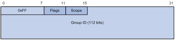
The following describes the fields of an IPv6 multicast address:
? 0xFF—The most significant eight bits are 11111111.
? Flags—The Flags field contains four bits.
Figure 5 Flags field format
![]()
Table 4 Flags field description
|
Bit |
Description |
|
0 |
Reserved, set to 0. |
|
R |
· When set to 0, this address is an IPv6 multicast address without an embedded RP address. · When set to 1, this address is an IPv6 multicast address with an embedded RP address. (The P and T bits must also be set to 1.) |
|
P |
· When set to 0, this address is an IPv6 multicast address not based on a unicast prefix. · When set to 1, this address is an IPv6 multicast address based on a unicast prefix. (The T bit must also be set to 1.) |
|
T |
· When set to 0, this address is an IPv6 multicast address permanently-assigned by IANA. · When set to 1, this address is a transient or dynamically assigned IPv6 multicast address. |
? Scope—The Scope field contains four bits, which represent the scope of the IPv6 internetwork for which the multicast traffic is intended.
Table 5 Values of the Scope field
|
Meaning |
|
|
0, F |
Reserved. |
|
1 |
Interface-local scope. |
|
2 |
Link-local scope. |
|
3 |
Subnet-local scope. |
|
4 |
Admin-local scope. |
|
5 |
Site-local scope. |
|
6, 7, 9 through D |
Unassigned. |
|
8 |
Organization-local scope. |
|
E |
Global scope. |
? Group ID—The Group ID field contains 112 bits. It uniquely identifies an IPv6 multicast group in the scope that the Scope field defines.
Ethernet multicast MAC addresses
· IPv4 multicast MAC addresses:
As defined by IANA, the most significant 24 bits of an IPv4 multicast MAC address are 0x01005E. Bit 25 is 0, and the other 23 bits are the least significant 23 bits of an IPv4 multicast address.
Figure 6 IPv4-to-MAC address mapping
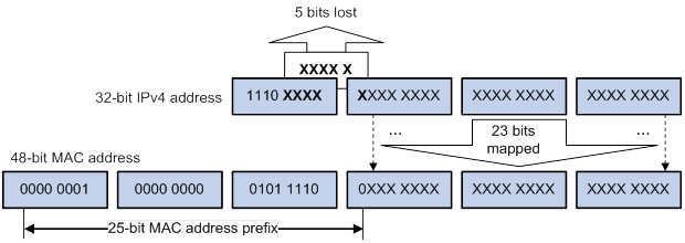
The most significant four bits of an IPv4 multicast address are fixed at 1110. In an IPv4-to-MAC address mapping, five bits of the IPv4 multicast address are lost. As a result, 32 IPv4 multicast addresses are mapped to the same IPv4 multicast MAC address. A device might receive unwanted multicast data at Layer 2 processing, which needs to be filtered by the upper layer.
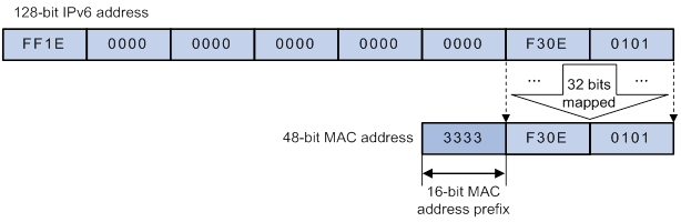
· IPv6 multicast MAC addresses:
As defined by IANA, the most significant 16 bits of an IPv6 multicast MAC address are 0x3333. The least significant 32 bits are mapped from the least significant 32 bits of an IPv6 multicast address. Therefore, the problem of duplicate IPv6-to-MAC address mapping also arises like IPv4-to-MAC address mapping.
Figure 7 IPv6-to-MAC address mapping
Multicast protocols
Multicast protocols include the following categories:
· Layer 3 and Layer 2 multicast protocols:
? Layer 3 multicast refers to IP multicast operating at the network layer.
Layer 3 multicast protocols—IGMP, MLD, PIM, IPv6 PIM, and MSDP.
? Layer 2 multicast refers to IP multicast operating at the data link layer.
Layer 2 multicast protocols—IGMP snooping and MLD snooping.
· IPv4 and IPv6 multicast protocols:
? For IPv4 networks—IGMP snooping, IGMP, PIM, and MSDP.
? For IPv6 networks—MLD snooping, MLD, and IPv6 PIM.
This section provides only general descriptions about applications and functions of the Layer 2 and Layer 3 multicast protocols in a network. For more information about these protocols, see the related chapters.
Layer 3 multicast protocols
In Figure 8, Layer 3 multicast protocols include multicast group management protocols and multicast routing protocols.
Figure 8 Positions of Layer 3 multicast protocols
· Multicast group management protocols:
Internet Group Management Protocol (IGMP) and Multicast Listener Discovery (MLD) protocol are multicast group management protocols. Typically, they run between hosts and Layer 3 multicast devices that directly connect to the hosts to establish and maintain multicast group memberships.
· Multicast routing protocols:
A multicast routing protocol runs on Layer 3 multicast devices to establish and maintain multicast routes and correctly and efficiently forward multicast packets. Multicast routes constitute loop-free data transmission paths (also known as multicast distribution trees) from a data source to multiple receivers.
In the ASM model, multicast routes include intra-domain routes and inter-domain routes.
? An intra-domain multicast routing protocol discovers multicast sources and builds multicast distribution trees within an AS to deliver multicast data to receivers. Among a variety of mature intra-domain multicast routing protocols, PIM is most widely used. Based on the forwarding mechanism, PIM has dense mode (often referred to as PIM-DM) and sparse mode (often referred to as PIM-SM).
? An inter-domain multicast routing protocol is used for delivering multicast information between two ASs. So far, mature solutions include Multicast Source Discovery Protocol (MSDP) and MBGP. MSDP propagates multicast source information among different ASs. MBGP is an extension of the MP-BGP for exchanging multicast routing information among different ASs.
For the SSM model, multicast routes are not divided into intra-domain routes and inter-domain routes. Because receivers know the positions of the multicast sources, channels established through PIM-SM are sufficient for the transport of multicast information.
Layer 2 multicast protocols
Layer 2 multicast protocols include IGMP snooping and MLD snooping.
IGMP snooping and MLD snooping are multicast constraining mechanisms that run on Layer 2 devices. They manage and control multicast groups by monitoring and analyzing IGMP or MLD messages exchanged between the hosts and Layer 3 multicast devices. This effectively controls the flooding of multicast data in Layer 2 networks.
Multicast packet forwarding mechanism
In a multicast model, receiver hosts of a multicast group are usually located at different areas on the network. They are identified by the same multicast group address. To deliver multicast packets to these receivers, a multicast source encapsulates the multicast data in an IP packet with the multicast group address as the destination address. Multicast routers on the forwarding paths forward multicast packets that an incoming interface receives through multiple outgoing interfaces. Compared to a unicast model, a multicast model is more complex in the following aspects:
· To ensure multicast packet transmission on the network, different routing tables are used to guide multicast forwarding. These routing tables include unicast routing tables, routing tables for multicast (for example, the MBGP routing table), and static multicast routing tables.
· To process the same multicast information from different peers received on different interfaces, the multicast device performs an RPF check on each multicast packet. The RPF check result determines whether the packet will be forwarded or discarded. The RPF check mechanism is the basis for most multicast routing protocols to implement multicast forwarding.
For more information about the RPF mechanism, see "Configuring multicast routing and forwarding" and "Configuring IPv6 multicast routing and forwarding."
Multicast support for VPNs
Multicast support for VPNs refers to multicast applied in VPNs.
Introduction to VPN instances
VPNs are isolated from one another and from the public network. As shown in Figure 9, VPN A and VPN B separately access the public network through PE devices.
Figure 9 VPN networking diagram
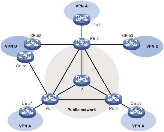
· The P device belongs to the public network. The CE devices belong to their respective VPNs. Each CE device serves its own VPN and maintains only one set of forwarding mechanisms.
Multicast application in VPNs
A PE device that supports multicast for VPNs performs the following operations:
· Maintains an independent set of multicast forwarding mechanisms for each VPN, including the multicast protocols, PIM neighbor information, and multicast routing table. In a VPN, the device forwards multicast data based on the forwarding table or routing table for that VPN.
· Implements the isolation between different VPNs.
· Implements information exchange and data conversion between the public network and VPN instances.
For example, as shown in Figure 9, a multicast source in VPN A sends multicast data to a multicast group. Only receivers that belong to both the multicast group and VPN A can receive the multicast data. The multicast data is multicast both in VPN A and on the public network.
Configuring IGMP snooping
Overview
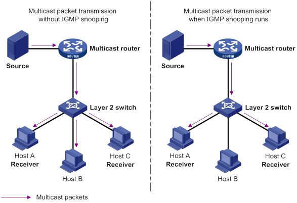
IGMP snooping runs on a Layer 2 device as a multicast constraining mechanism to improve multicast forwarding efficiency. It creates Layer 2 multicast forwarding entries from IGMP packets that are exchanged between the hosts and the router.
As shown in Figure 10, when IGMP snooping is not enabled, the Layer 2 switch floods multicast packets to all hosts in a VLAN. When IGMP snooping is enabled, the Layer 2 switch forwards multicast packets of known multicast groups to only the receivers.
Figure 10 Multicast packet transmission without and with IGMP snooping
IGMP snooping ports
As shown in Figure 11, IGMP snooping runs on Switch A and Switch B, and Host A and Host C are receivers in a multicast group. IGMP snooping ports are divided into member ports and router ports.
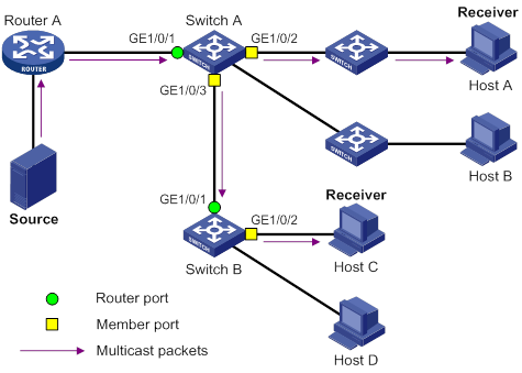
Router ports
On an IGMP snooping Layer 2 device, the ports toward Layer 3 multicast devices are called router ports. In Figure 11, GigabitEthernet 1/0/1 of Switch A and GigabitEthernet 1/0/1 of Switch B are router ports.
Router ports contain the following types:
· Dynamic router port—When a port receives an IGMP general query whose source address is not 0.0.0.0 or receives a PIM hello message, the port is added into the dynamic router port list. At the same time, an aging timer is started for the port. If the port receives either of the messages before the timer expires, the timer is reset. If the port does not receive either of the messages when the timer expires, the port is removed from the dynamic router port list.
· Static router port—When a port is statically configured as a router port, it is added into the static router port list. The static router port does not age out, and it can be deleted only manually.
Do not confuse the "router port" in IGMP snooping with the "routed interface" commonly known as the "Layer 3 interface." The router port in IGMP snooping is a Layer 2 interface.
Member ports
On an IGMP snooping Layer 2 device, the ports toward receiver hosts are called member ports. In Figure 11, GigabitEthernet 1/0/2 and GigabitEthernet 1/0/3 of Switch A and GigabitEthernet 1/0/2 of Switch B are member ports.
Member ports contain the following types:
· Dynamic member port—When a port receives an IGMP report, it is added to the associated dynamic IGMP snooping forwarding entry as an outgoing interface. At the same time, an aging timer is started for the port. If the port receives an IGMP report before the timer expires, the timer is reset. If the port does not receive an IGMP report when the timer expires, the port is removed from the associated dynamic forwarding entry.
· Static member port—When a port is statically configured as a member port, it is added to the associated static IGMP snooping forwarding entry as an outgoing interface. The static member port does not age out, and it can be deleted only manually.
Unless otherwise specified, router ports and member ports in this document include both static and dynamic router ports and member ports.
How IGMP snooping works
The ports in this section are dynamic ports. For information about how to configure and remove static ports, see "Configuring static ports."
IGMP messages types include general query, IGMP report, and leave message. An IGMP snooping-enabled Layer 2 device performs differently depending on the message types.
General query
The IGMP querier periodically sends IGMP general queries to all hosts and routers on the local subnet to check for the existence of multicast group members.
After receiving an IGMP general query, the Layer 2 device forwards the query to all ports in the VLAN except the receiving port. The Layer 2 device also performs one of the following actions:
· If the receiving port is a dynamic router port in the dynamic router port list, the Layer 2 device restarts the aging timer for the port.
· If the receiving port does not exist in the dynamic router port list, the Layer 2 device adds the port to the dynamic router port list. It also starts an aging timer for the port.
IGMP report
A host sends an IGMP report to the IGMP querier for the following purposes:
· Responds to queries if the host is a multicast group member.
· Applies for a multicast group membership.
After receiving an IGMP report from a host, the Layer 2 device forwards the report through all the router ports in the VLAN. It also resolves the address of the reported multicast group, and looks up the forwarding table for a matching entry as follows:
· If no match is found, the Layer 2 device creates a forwarding entry with the receiving port as an outgoing interface. It also marks the receiving port as a dynamic member port and starts an aging timer for the port.
· If a match is found but the matching forwarding entry does not contain the receiving port, the Layer 2 device adds the receiving port to the outgoing interface list. It also marks the receiving port as a dynamic member port and starts an aging timer for the port.
· If a match is found and the matching forwarding entry contains the receiving port, the Layer 2 device restarts the aging timer for the port.
In an application with a group policy configured on an IGMP snooping-enabled Layer 2 device, when a user requests a multicast program, the user's host initiates an IGMP report. After receiving this report, the Layer 2 device resolves the multicast group address in the report and performs ACL filtering on the report. If the report passes ACL filtering, the Layer 2 device creates an IGMP snooping forwarding entry for the multicast group with the receiving port as an outgoing interface. If the report does not pass ACL filtering, the Layer 2 device drops this report. The multicast data for the multicast group is not sent to this port, and the user cannot retrieve the program.
A Layer 2 device does not forward an IGMP report through a non-router port because of the host IGMP report suppression mechanism. For more information about the IGMP report suppression mechanism, see "Configuring IGMP."
Leave message
An IGMPv1 receiver host does not send any leave messages when it leaves a multicast group. The Layer 2 device cannot immediately update the status of the port that connects to the receiver host. The Layer 2 device does not remove the port from the outgoing interface list in the associated forwarding entry until the aging time for the group expires.
An IGMPv2 or IGMPv3 host sends an IGMP leave message when it leaves a multicast group.
When the Layer 2 device receives an IGMP leave message on a dynamic member port, the Layer 2 device first examines whether a forwarding entry matches the group address in the message.
· If no match is found, the Layer 2 device discards the IGMP leave message.
· If a match is found but the receiving port is not an outgoing interface in the forwarding entry, the Layer 2 device discards the IGMP leave message.
· If a match is found and the receiving port is not the only outgoing interface in the forwarding entry, the Layer 2 device performs the following actions:
? Discards the IGMP leave message.
? Sends an IGMP group-specific query to identify whether the group has active receivers attached to the receiving port.
? Sets the aging timer for the receiving port to twice the IGMP last member query interval.
· If a match is found and the receiving port is the only outgoing interface in the forwarding entry, the Layer 2 device performs the following actions:
? Forwards the IGMP leave message to all router ports in the VLAN.
? Sends an IGMP group-specific query to identify whether the group has active receivers attached to the receiving port.
? Sets the aging timer for the receiving port to twice the IGMP last member query interval.
After receiving the IGMP leave message on a port, the IGMP querier resolves the multicast group address in the message. Then, it sends an IGMP group-specific query to the multicast group through the receiving port.
After receiving the IGMP group-specific query, the Layer 2 device forwards the query through all its router ports in the VLAN and all member ports of the multicast group. Then, it waits for the responding IGMP report from the directly connected hosts. For the dynamic member port that received the leave message, the Layer 2 device also performs one of the following actions:
· If the port receives an IGMP report before the aging timer expires, the Layer 2 device resets the aging timer.
· If the port does not receive an IGMP report when the aging timer expires, the Layer 2 device removes the port from the forwarding entry for the multicast group.
Protocols and standards
RFC 4541, Considerations for Internet Group Management Protocol (IGMP) and Multicast Listener Discovery (MLD) Snooping Switches
Compatibility information
Feature and hardware compatibility
This feature is supported only on the following ports:
· Layer 2 Ethernet ports on the following modules:
? HMIM-8GSW.
? HMIM-8GSWF.
? HMIM-24GSW/24GSW-PoE.
? SIC-4GSW/4GSWF/4GSW-PoE.
? SIC-9FSW/9FSW-PoE.
· Fixed Layer 2 Ethernet ports on the following routers:
? MSR810/810-W/810-W-DB/810-LM/810-W-LM/810-10-PoE/810-LM-HK/810-W-LM-HK.
? MSR2600-6-X1/2600-10-X1.
? MSR3600-28/3600-51.
Command and hardware compatibility
Commands and descriptions for centralized devices apply to the following routers:
· MSR810/810-W/810-W-DB/810-LM/810-W-LM/810-10-PoE/810-LM-HK/810-W-LM-HK.
· MSR2600-6-X1/2600-10-X1.
· MSR 2630.
· MSR3600-28/3600-51.
· MSR3610-X1/3610-X1-DP/3610-X1-DC/3610-X1-DP-DC.
· MSR 3610/3620/3620-DP/3640/3660.
· MSR810-LM-GL/810-W-LM-GL/830-6EI-GL/830-10EI-GL/830-6HI-GL/830-10HI-GL/2600-6-X1-GL.
Commands and descriptions for distributed devices apply to the following routers:
· MSR5620.
· MSR 5660.
· MSR 5680.
IGMP snooping configuration task list
You can configure IGMP snooping for VLANs.
The IGMP snooping configurations made on Layer 2 aggregate interfaces do not interfere with the configurations made on member ports. In addition, the configurations made on Layer 2 aggregate interfaces do not take part in aggregation calculations. The configuration made on a member port of the aggregate group takes effect after the port leaves the aggregate group.
Configuring basic IGMP snooping features
Before you configure basic IGMP snooping features, complete the following tasks:
· Configure VLANs.
· Determine the IGMP snooping version.
· Determine the maximum number of IGMP snooping forwarding entries.
· Determine the IGMP last member query interval.
Enabling IGMP snooping
When you enable IGMP snooping, follow these restrictions and guidelines:
· You must enable IGMP snooping globally before you enable it for a VLAN.
· IGMP snooping configuration made in VLAN view takes effect only on the member ports in that VLAN.
· You can enable IGMP snooping for the specified VLANs in IGMP-snooping view or for a VLAN in VLAN view. For a VLAN, the configuration in VLAN view has the same priority as the configuration in IGMP-snooping view, and the most recent configuration takes effect.
To enable IGMP snooping for the specified VLANs:
|
Step |
Command |
Remarks |
|
1. Enter system view. |
system-view |
N/A |
|
2. Enable IGMP snooping globally and enter IGMP-snooping view. |
igmp-snooping |
By default, IGMP snooping is globally disabled. |
|
3. Enable IGMP snooping for the specified VLANs. |
enable vlan vlan-list |
By default, IGMP snooping is disabled for a VLAN. |
To enable IGMP snooping for a VLAN:
|
Step |
Command |
Remarks |
|
1. Enter system view. |
system-view |
N/A |
|
2. Enable IGMP snooping globally and enter IGMP-snooping view. |
igmp-snooping |
By default, IGMP snooping is globally disabled. |
|
3. Return to system view. |
quit |
N/A |
|
4. Enter VLAN view. |
vlan vlan-id |
N/A |
|
5. Enable IGMP snooping for the VLAN. |
igmp-snooping enable |
By default, IGMP snooping is disabled in a VLAN. |
Specifying an IGMP snooping version
Different IGMP snooping versions process different versions of IGMP messages.
· IGMPv2 snooping processes IGMPv1 and IGMPv2 messages, but it floods IGMPv3 messages in the VLAN instead of processing them.
· IGMPv3 snooping processes IGMPv1, IGMPv2, and IGMPv3 messages.
If you change IGMPv3 snooping to IGMPv2 snooping, the device does the following:
· Clears all IGMP snooping forwarding entries that are dynamically added.
· Keeps static IGMPv3 snooping forwarding entries (*, G).
· Clears static IGMPv3 snooping forwarding entries (S, G), which will be restored when IGMP snooping is switched back to IGMPv3 snooping.
For more information about static IGMP snooping forwarding entries, see "Configuring static ports."
You can specify the version for the specified VLANs in IGMP-snooping view or for a VLAN in VLAN view. For a VLAN, the configuration in VLAN view has the same priority as the configuration in IGMP-snooping view, and the most recent configuration takes effect.
To specify an IGMP snooping version for the specified VLANs:
|
Step |
Command |
Remarks |
|
1. Enter system view. |
system-view |
N/A |
|
2. Enable IGMP snooping globally and enter IGMP-snooping view. |
igmp-snooping |
N/A |
|
3. Specify an IGMP snooping version for the specified VLANs. |
version version-number vlan vlan-list |
The default setting is 2. |
To specify an IGMP snooping version for a VLAN:
|
Step |
Command |
Remarks |
|
1. Enter system view. |
system-view |
N/A |
|
2. Enter VLAN view. |
vlan vlan-id |
N/A |
|
3. Specify an IGMP snooping version for the VLAN. |
igmp-snooping version version-number |
The default setting is 2. |
Setting the maximum number of IGMP snooping forwarding entries
You can modify the maximum number of IGMP snooping forwarding entries, including dynamic entries and static entries. When the number of forwarding entries on the device reaches the upper limit, the device does not automatically remove any existing entries. As a best practice, manually remove some entries to allow new entries to be created.
To set the maximum number of IGMP snooping forwarding entries:
|
Step |
Command |
Remarks |
|
1. Enter system view. |
system-view |
N/A |
|
2. Enter IGMP-snooping view. |
igmp-snooping |
N/A |
|
3. Set the maximum number of IGMP snooping forwarding entries. |
entry-limit limit |
The default setting is 4294967295. |
Setting the IGMP last member query interval
A receiver host starts a report delay timer for a multicast group when it receives an IGMP group-specific query for the group. This timer is set to a random value in the range of 0 to the maximum response time advertised in the query. When the timer value decreases to 0, the host sends an IGMP report to the group.
The IGMP last member query interval defines the maximum response time advertised in IGMP group-specific queries. Set an appropriate value for the IGMP last member query interval to speed up hosts' responses to IGMP group-specific queries and avoid IGMP report traffic bursts.
Configuration restrictions and guidelines
When you set the IGMP last member query interval, follow these restrictions and guidelines:
· The Layer 2 device does not send an IGMP group-specific query if it receives an IGMP leave message from a port enabled with fast-leave processing.
· You can set the IGMP last member query interval globally for all VLANs in IGMP-snooping view or for a VLAN in VLAN view. For a VLAN, the VLAN-specific configuration takes priority over the global configuration.
Setting the IGMP last member query interval globally
|
Step |
Command |
Remarks |
|
1. Enter system view. |
system-view |
N/A |
|
2. Enter IGMP-snooping view. |
igmp-snooping |
N/A |
|
3. Set the IGMP last member query interval globally. |
last-member-query-interval interval |
The default setting is 1 second. |
Setting the IGMP last member query interval in a VLAN
|
Step |
Command |
Remarks |
|
1. Enter system view. |
system-view |
N/A |
|
2. Enter VLAN view. |
vlan vlan-id |
N/A |
|
3. Set the IGMP last member query interval for the VLAN. |
igmp-snooping last-member-query-interval interval |
The default setting is 1 second. |
Configuring IGMP snooping port features
Before you configure IGMP snooping port features, complete the following tasks:
· Enable IGMP snooping for the VLAN.
· Determine the aging timer for dynamic router ports.
· Determine the aging timer for dynamic member ports.
· Determine the addresses of the multicast group and multicast source.
Setting aging timers for dynamic ports
When you set aging timers for dynamic ports, follow these restrictions and guidelines:
· If the memberships of multicast groups frequently change, you can set a relatively small value for the aging timer of the dynamic member ports. If the memberships of multicast groups rarely change, you can set a relatively large value.
· If a dynamic router port receives a PIMv2 hello message, the aging timer for the port is specified by the hello message. In this case, the router-aging-time or igmp-snooping router-aging-time command does not take effect on the port.
· IGMP group-specific queries originated by the Layer 2 device trigger the adjustment of aging timers for dynamic member ports. If a dynamic member port receives such a query, its aging timer is set to twice the IGMP last member query interval. For more information about setting the IGMP last member query interval on the Layer 2 device, see "Setting the IGMP last member query interval."
· You can set the timers globally for all VLANs in IGMP-snooping view or for a VLAN in VLAN view. For a VLAN, the VLAN-specific configuration takes priority over the global configuration.
Setting the aging timers for dynamic ports globally
|
Step |
Command |
Remarks |
|
1. Enter system view. |
system-view |
N/A |
|
2. Enter IGMP-snooping view. |
igmp-snooping |
N/A |
|
3. Set the aging timer for dynamic router ports globally. |
router-aging-time seconds |
The default setting is 260 seconds. |
|
4. Set the global aging timer for dynamic member ports globally. |
host-aging-time seconds |
The default setting is 260 seconds. |
Setting the aging timers for dynamic ports in a VLAN
|
Step |
Command |
Remarks |
|
1. Enter system view. |
system-view |
N/A |
|
2. Enter VLAN view. |
vlan vlan-id |
N/A |
|
3. Set the aging timer for dynamic router ports in the VLAN. |
igmp-snooping router-aging-time seconds |
The default setting is 260 seconds. |
|
4. Set the aging timer for dynamic member ports in the VLAN. |
igmp-snooping host-aging-time seconds |
The default setting is 260 seconds. |
Configuring static ports
You can configure the following types of static ports:
· Static member port—When you configure a port as a static member port for a multicast group, all hosts attached to the port will receive multicast data for the group.
The static member port does not respond to IGMP queries. When you complete or cancel this configuration on a port, the port does not send an unsolicited IGMP report or leave message.
· Static router port—When you configure a port as a static router port for a multicast group, all multicast data for the group received on the port will be forwarded.
To configure static ports:
|
Step |
Command |
Remarks |
|
1. Enter system view. |
system-view |
N/A |
|
2. Enter Layer 2 Ethernet interface view or Layer 2 aggregate interface view. |
interface interface-type interface-number |
N/A |
|
3. Configure the port as a static port. |
·
Configure the port as a static member port: ·
Configure the port as a static router port: |
By default, a port is not a static member port or a static router port. |
Configuring a port as a simulated member host
When a port is configured as a simulated member host, it is equivalent to an independent host in the following ways:
· It sends an unsolicited IGMP report when you complete the configuration.
· It responds to IGMP general queries with IGMP reports.
· It sends an IGMP leave message when you cancel the configuration.
The version of IGMP running on the simulated member host is the same as the version of IGMP snooping running on the port. The port ages out in the same way as a dynamic member port.
To configure a port as a simulated member host:
|
Step |
Command |
Remarks |
|
1. Enter system view. |
system-view |
N/A |
|
2. Enter Layer 2 Ethernet interface view or Layer 2 aggregate interface view. |
N/A |
|
|
3. Configure the port as a simulated member host. |
igmp-snooping host-join group-address [ source-ip source-address ] vlan vlan-id |
By default, the port is not a simulated member host. |
Enabling fast-leave processing
This feature enables the device to immediately remove a port from the forwarding entry for a multicast group when the port receives a leave massage.
Configuration restrictions and guidelines
When you enable fast-leave processing, follow these restrictions and guidelines:
· Do not enable fast-leave processing on a port that has multiple receiver hosts in a VLAN. If fast-leave processing is enabled, the remaining receivers cannot receive multicast data for a group after a receiver leaves that group.
Configuration procedure
To enable fast-leave processing globally:
|
Step |
Command |
Remarks |
|
1. Enter system view. |
system-view |
N/A |
|
2. Enter IGMP-snooping view. |
igmp-snooping |
N/A |
|
3. Enable fast-leave processing globally. |
fast-leave [ vlan vlan-list ] |
By default, fast-leave processing is disabled globally. |
To enable fast-leave processing on a port:
|
Step |
Command |
Remarks |
|
1. Enter system view. |
system-view |
N/A |
|
2. Enter Layer 2 Ethernet interface view or Layer 2 aggregate interface view. |
interface interface-type interface-number |
N/A |
|
3. Enable fast-leave processing on the port. |
igmp-snooping fast-leave [ vlan vlan-list ] |
By default, fast-leave processing is disabled on a port. |
Disabling a port from becoming a dynamic router port
A receiver host might send IGMP general queries or PIM hello messages for testing purposes. On the Layer 2 device, the port that receives either of the messages becomes a dynamic router port. Before the aging timer for the port expires, the following problems might occur:
· All multicast data for the VLAN to which the port belongs flows to the port. Then, the port forwards the data to attached receiver hosts. The receiver hosts will receive multicast data that it does not want to receive.
· The port forwards the IGMP general queries or PIM hello messages to its upstream multicast routers. These messages might affect the multicast routing protocol state (such as the IGMP querier or DR election) on the multicast routers. This might further cause network interruption.
To solve these problems, you can disable a port from becoming a dynamic router port. This also improves network security and the control over receiver hosts.
To disable a port from becoming a dynamic router port:
|
Step |
Command |
Remarks |
|
1. Enter system view. |
system-view |
N/A |
|
2. Enter Layer 2 Ethernet interface view or Layer 2 aggregate interface view. |
interface interface-type interface-number |
N/A |
|
3. Disable the port from becoming a dynamic router port. |
igmp-snooping router-port-deny [ vlan vlan-list ] |
By default, a port is allowed to become a dynamic router port. This configuration does not affect the static router port configuration. |
Configuring the IGMP snooping querier
This section describes how to configure an IGMP snooping querier.
Configuration prerequisites
Before you configure the IGMP snooping querier, complete the following tasks:
· Enable IGMP snooping for the VLAN.
· Determine the IGMP general query interval.
· Determine the maximum response time for IGMP general queries.
Enabling the IGMP snooping querier
Configuration restrictions and guidelines
Do not enable the IGMP snooping querier on a multicast network that runs IGMP. An IGMP snooping querier does not take part in IGMP querier elections. However, it might affect IGMP querier elections if it sends IGMP general queries with a low source IP address.
Configuration procedure
To enable the IGMP snooping querier for a VLAN:
|
Step |
Command |
Remarks |
|
1. Enter system view. |
system-view |
N/A |
|
2. Enter VLAN view. |
vlan vlan-id |
N/A |
|
3. Enable the IGMP snooping querier. |
igmp-snooping querier |
By default, the IGMP snooping querier is disabled. |
Configuring parameters for IGMP general queries and responses
|
|
CAUTION: To avoid mistakenly deleting multicast group members, make sure the IGMP general query interval is greater than the maximum response time for IGMP general queries. |
You can modify the IGMP general query interval for a VLAN based on the actual condition of the network.
A receiver host starts a report delay timer for each multicast group that it has joined when it receives an IGMP general query. This timer is set to a random value in the range of 0 to the maximum response time advertised in the query. When the timer value decreases to 0, the host sends an IGMP report to the corresponding multicast group.
Set an appropriate value for the maximum response time for IGMP general queries to speed up hosts' responses to IGMP general queries and avoid IGMP report traffic bursts.
You can set the maximum response time for IGMP general queries globally for all VLANs in IGMP-snooping view or for a VLAN in VLAN view. For a VLAN, the VLAN-specific configuration takes priority over the global configuration.
Configuring parameters for IGMP general queries and responses globally
|
Step |
Command |
Remarks |
|
1. Enter system view. |
system-view |
N/A |
|
2. Enter IGMP-snooping view. |
igmp-snooping |
N/A |
|
3. Set the maximum response time for IGMP general queries. |
max-response-time seconds |
The default setting is 10 seconds. |
Configuring parameters for IGMP general queries and responses in a VLAN
|
Step |
Command |
Remarks |
|
1. Enter system view. |
system-view |
N/A |
|
2. Enter VLAN view. |
vlan vlan-id |
N/A |
|
3. Set the IGMP general query interval in the VLAN. |
igmp-snooping query-interval interval |
The default setting is 125 seconds. |
|
4. Set the maximum response time for IGMP general queries in the VLAN. |
igmp-snooping max-response-time seconds |
The default setting is 10 seconds. |
Configuring parameters for IGMP messages
This section describes how to configure parameters for IGMP messages.
Configuration prerequisites
Before you configure parameters for IGMP messages, complete the following tasks:
· Enable IGMP snooping for the VLAN.
· Determine the source IP address of IGMP general queries.
· Determine the source IP address of IGMP group-specific queries.
· Determine the source IP address of IGMP reports.
· Determine the source IP address of IGMP leave messages.
· Determine the 802.1p priority of IGMP messages.
Configuring source IP addresses for IGMP messages
The IGMP snooping querier might send IGMP general queries with the source IP address 0.0.0.0. The port that receives such queries will not be maintained as a dynamic router port. This might prevent the associated dynamic IGMP snooping forwarding entry from being correctly created at the data link layer and eventually cause multicast traffic forwarding failures.
To avoid this problem, you can configure a non-all-zero IP address as the source IP address of the IGMP queries on the IGMP snooping querier. This configuration might affect the IGMP querier election within the subnet.
You can also change the source IP address of IGMP reports or leave messages sent by a simulated member host or an IGMP snooping proxy.
To configure source IP addresses for IGMP messages in a VLAN:
|
Step |
Command |
Remarks |
|
1. Enter system view. |
system-view |
N/A |
|
2. Enter VLAN view. |
vlan vlan-id |
N/A |
|
3. Configure the source IP address for IGMP general queries. |
igmp-snooping general-query source-ip ip-address |
By default, the source IP address of IGMP general queries is the IP address of the current VLAN interface. If the current VLAN interface does not have an IP address, the source IP address is 0.0.0.0. |
|
4. Configure the source IP address for IGMP group-specific queries. |
igmp-snooping special-query source-ip ip-address |
By default, the source IP address of IGMP group-specific queries is one of the following: · The source address of IGMP group-specific queries if the IGMP snooping querier has received IGMP general queries. · The IP address of the current VLAN interface if the IGMP snooping querier does not receive an IGMP general query. · 0.0.0.0 if the IGMP snooping querier does not receive an IGMP general query and the current VLAN interface does not have an IP address. |
|
5. Configure the source IP address for IGMP reports. |
By default, the source IP address of IGMP reports is the IP address of the current VLAN interface. If the current VLAN interface does not have an IP address, the source IP address is 0.0.0.0. |
|
|
6. Configure the source IP address for IGMP leave messages. |
By default, the source IP address of IGMP leave messages is the IP address of the current VLAN interface. If the current VLAN interface does not have an IP address, the source IP address is 0.0.0.0. |
Setting the 802.1p priority for IGMP messages
When congestion occurs on outgoing ports of the Layer 2 device, it forwards IGMP messages in their 802.1p priority order, from highest to lowest. You can assign a higher 802.1p priority to IGMP messages that are created or forwarded by the device.
You can set the 802.1p priority globally for all VLANs in IGMP-snooping view or for a VLAN in VLAN view. For a VLAN, the VLAN-specific configuration takes priority over the global configuration.
Setting the 802.1p priority for IGMP messages globally
|
Step |
Command |
Remarks |
|
1. Enter system view. |
system-view |
N/A |
|
2. Enter IGMP-snooping view. |
igmp-snooping |
N/A |
|
3. Set the 802.1p priority for IGMP messages. |
dot1p-priority priority |
By default, the 802.1p priority for IGMP packets is not set. |
Setting the 802.1p priority for IGMP messages in a VLAN
|
Step |
Command |
Remarks |
|
1. Enter system view. |
system-view |
N/A |
|
2. Enter VLAN view. |
vlan vlan-id |
N/A |
|
3. Set the 802.1p priority for IGMP messages in the VLAN. |
igmp-snooping dot1p-priority priority |
By default, the 802.1p priority for IGMP packets is not set. |
Configuring IGMP snooping policies
Before you configure IGMP snooping policies, complete the following tasks:
· Enable IGMP snooping for the VLAN.
· Determine the ACL used by the multicast group policy.
· Determine the maximum number of multicast groups that a port can join.
Configuring a multicast group policy
This feature enables the device to filter IGMP reports by using an ACL that specifies the multicast groups and the optional sources. It is used to control the multicast groups that hosts can join.
Configuration restrictions and guidelines
When you configure a multicast group policy, follow these restrictions and guidelines:
· This configuration takes effect only on the multicast groups that ports join dynamically.
· You can configure a multicast group policy globally for all ports in IGMP-snooping view or for a port in interface view. For a port, the port-specific configuration takes priority over the global configuration.
Configuration procedure
To configure a multicast group policy globally:
|
Step |
Command |
Remarks |
|
1. Enter system view. |
system-view |
N/A |
|
2. Enter IGMP-snooping view. |
igmp-snooping |
N/A |
|
3. Configure a multicast group policy globally. |
group-policy ipv4-acl-number [ vlan vlan-list ] |
By default, no multicast group policies exist, and hosts can join any multicast groups. |
To configure a multicast group policy on a port:
|
Step |
Command |
Remarks |
|
1. Enter system view. |
system-view |
N/A |
|
2. Enter Layer 2 Ethernet interface view or Layer 2 aggregate interface view. |
interface interface-type interface-number |
N/A |
|
3. Configure a multicast group policy on the port. |
igmp-snooping group-policy ipv4-acl-number [ vlan vlan-list ] |
By default, no multicast group policies exist on a port, and hosts attached to the port can join any multicast groups. |
Enabling multicast source port filtering
This feature is supported only on the following ports:
· Layer 2 Ethernet ports on the following modules:
? HMIM-8GSW.
? HMIM-8GSWF.
? HMIM-24GSW/24GSW-PoE.
· Fixed Layer 2 Ethernet ports on the following routers:
? MSR810/810-W/810-W-DB/810-LM/810-W-LM/810-10-PoE/810-LM-HK/810-W-LM-HK.
? MSR2600-6-X1/2600-10-X1.
? MSR3600-28/3600-51.
This feature enables the device to discard all multicast data packets and to accept multicast protocol packets. You can enable this feature on ports that connect only to multicast receivers.
You can enable this feature for the specified ports in IGMP-snooping view or for a port in interface view. For a port, the configuration in interface view has the same priority as the configuration in IGMP-snooping view, and the most recent configuration takes effect.
Enabling multicast source port filtering for the specified ports
|
Step |
Command |
Remarks |
|
1. Enter system view. |
system-view |
N/A |
|
2. Enter IGMP-snooping view. |
igmp-snooping |
N/A |
|
3. Enable multicast source port filtering. |
source-deny port interface-list |
By default, multicast source port filtering is disabled. |
Enabling multicast source port filtering for a port
|
Step |
Command |
Remarks |
|
1. Enter system view. |
system-view |
N/A |
|
2. Enter Layer 2 Ethernet interface view. |
interface interface-type interface-number |
N/A |
|
3. Enable multicast source port filtering. |
igmp-snooping source-deny |
By default, multicast source port filtering is disabled. |
Enabling dropping unknown multicast data
This feature is supported only on the following ports:
· Layer 2 Ethernet ports on the following modules:
? HMIM-8GSW.
? HMIM-8GSWF.
? HMIM-24GSW/24GSW-PoE.
? SIC-4GSW/4GSWF/4GSW-PoE.
· Fixed Layer 2 Ethernet ports on the following routers:
? MSR810/810-W/810-W-DB/810-LM/810-W-LM/810-10-PoE/810-LM-HK/810-W-LM-HK.
? MSR2600-6-X1/2600-10-X1.
? MSR3600-28/3600-51.
This feature enables the device to drop all unknown multicast data. Unknown multicast data refers to multicast data for which no forwarding entries exist in the IGMP snooping forwarding table.
If you do not enable this feature, the unknown multicast data is flooded in the VLAN to which the data belongs.
For a device installed with the SIC-4GSW, SIC-4GSWF, or SIC-4GSW-PoE module, unknown IPv6 multicast data is dropped for a VLAN enabled with dropping unknown IPv4 multicast data.
To enable dropping unknown multicast data for a VLAN:
|
Step |
Command |
Remarks |
|
1. Enter system view. |
system-view |
N/A |
|
2. Enter VLAN view. |
vlan vlan-id |
N/A |
|
3. Enable dropping unknown multicast data for the VLAN. |
igmp-snooping drop-unknown |
By default, dropping unknown multicast data is disabled, and unknown multicast data is flooded. |
Enabling IGMP report suppression
This feature enables the device to forward only the first IGMP report for a multicast group to its directly connected Layer 3 device. Other reports for the same group in the same query interval are discarded. Use this feature to reduce multicast traffic.
To enable IGMP report suppression:
|
Step |
Command |
Remarks |
|
1. Enter system view. |
system-view |
N/A |
|
2. Enter IGMP-snooping view. |
igmp-snooping |
N/A |
|
3. Enable IGMP report suppression. |
report-aggregation |
By default, IGMP report suppression is enabled. |
Setting the maximum number of multicast groups on a port
You can set the maximum number of multicast groups on a port to regulate the port traffic.
Configuration restrictions and guidelines
When you set the maximum number of multicast groups on a port, follow these restrictions and guidelines:
· This configuration takes effect only on the multicast groups that a port joins dynamically.
· If the number of multicast groups on a port exceeds the limit, the system removes all the forwarding entries related to that port. The receiver hosts attached to that port can join multicast groups again before the number of multicast groups on the port reaches the limit.
Configuration procedure
To set the maximum number of multicast groups on a port:
|
Step |
Command |
Remarks |
|
1. Enter system view. |
system-view |
N/A |
|
2. Enter Layer 2 Ethernet interface view or Layer 2 aggregate interface view. |
interface interface-type interface-number |
N/A |
|
3. Set the maximum number of multicast groups on a port. |
igmp-snooping group-limit limit [ vlan vlan-list ] |
By default, no limit is placed on the maximum number of multicast groups on a port. |
Enabling the multicast group replacement feature
When multicast group replacement is enabled, the port does not drop IGMP reports for new groups if the number of multicast groups on the port reaches the upper limit. Instead, the port leaves the multicast group that has the lowest IP address and joins the new group contained in the IGMP report. The multicast group replacement feature is typically used in the channel switching application.
Configuration restrictions and guidelines
When you enable the multicast group replacement feature, follow these restrictions and guidelines:
· This configuration takes effect only on the multicast groups that a port joins dynamically.
· You can enable this feature globally for all ports in IGMP-snooping view or for a port in interface view. For a port, the port-specific configuration takes priority over the global configuration.
· This feature does not take effect if the following conditions exist:
? The number of the IGMP snooping forwarding entries on the device reaches the upper limit.
? The multicast group that the port newly joins is not included in the multicast group list maintained by the device.
Configuration procedure
To enable the multicast group replacement feature globally:
|
Step |
Command |
Remarks |
|
1. Enter system view. |
system-view |
N/A |
|
2. Enter IGMP-snooping view. |
igmp-snooping |
N/A |
|
3. Enable the multicast group replacement feature globally. |
overflow-replace [ vlan vlan-list ] |
By default, the multicast group replacement feature is disabled globally. |
To enable the multicast group replacement feature on a port:
|
Step |
Command |
Remarks |
|
1. Enter system view. |
system-view |
N/A |
|
2. Enter Layer 2 Ethernet interface view or Layer 2 aggregate interface view. |
interface interface-type interface-number |
N/A |
|
3. Enable multicast group replacement feature on a port. |
igmp-snooping overflow-replace [ vlan vlan-list ] |
By default, the multicast group replacement feature is disabled on a port. |
Displaying and maintaining IGMP snooping
Execute display commands in any view and reset commands in user view.
|
Command |
|
|
Display IGMP snooping status. |
display igmp-snooping [ global | vlan vlan-id ] |
|
Display dynamic IGMP snooping group entries (Centralized devices in IRF mode). |
display igmp-snooping group [ group-address | source-address ] * [ vlan vlan-id ] [ verbose ] |
|
Display dynamic IGMP snooping group entries (Centralized devices in IRF mode/distributed devices in standalone mode). |
display igmp-snooping group [ group-address | source-address ] * [ vlan vlan-id ] [ verbose ] [ slot slot-number ] |
|
Display dynamic IGMP snooping group entries (Distributed devices in IRF mode). |
display igmp-snooping group [ group-address | source-address ] * [ vlan vlan-id ] [ verbose ] [ chassis chassis-number slot slot-number ] |
|
Display dynamic router port information (Centralized devices in standalone mode). |
display igmp-snooping router-port [ verbose | vlan vlan-id [ verbose ] ] |
|
Display dynamic router port information (Centralized devices in IRF mode/distributed devices in standalone mode). |
display igmp-snooping router-port [ verbose | vlan vlan-id [ verbose ] ] [ slot slot-number ] |
|
Display dynamic router port information (Distributed devices in IRF mode). |
display igmp-snooping router-port [ verbose | vlan vlan-id [ verbose ] ] [ chassis chassis-number slot slot-number ] |
|
Display static IGMP snooping group entries (Centralized devices in standalone mode). |
display igmp-snooping static-group [ group-address | source-address ] * [ vlan vlan-id ] [ verbose ] |
|
Display static IGMP snooping group entries (Centralized devices in IRF mode/distributed devices in standalone mode). |
display igmp-snooping static-group [ group-address | source-address ] * [ vlan vlan-id ] [ verbose ] [ slot slot-number ] |
|
Display static IGMP snooping group entries (Distributed devices in IRF mode). |
display igmp-snooping static-group [ group-address | source-address ] * [ vlan vlan-id ] [ verbose ] [ chassis chassis-number slot slot-number ] |
|
Display static router port information (Centralized devices in standalone mode). |
display igmp-snooping static-router-port [ vlan vlan-id ] |
|
Display static router port information (Centralized devices in IRF mode/distributed devices in standalone mode). |
display igmp-snooping static-router-port [ vlan vlan-id ] [ slot slot-number ] |
|
Display static router port information (Distributed devices in IRF mode). |
display igmp-snooping static-router-port [ vlan vlan-id ] [ chassis chassis-number slot slot-number ] |
|
Display statistics for the IGMP messages and PIMv2 hello messages learned by IGMP snooping. |
display igmp-snooping statistics |
|
Display Layer 2 multicast fast forwarding entries (Centralized devices in standalone mode). |
display l2-multicast fast-forwarding cache [ vlan vlan-id ] [ source-address | group-address ] * |
|
Display Layer 2 multicast fast forwarding entries (Centralized devices in IRF mode/distributed devices in standalone mode). |
display l2-multicast fast-forwarding cache [ vlan vlan-id ] [ source-address | group-address ] * [ slot slot-number ] |
|
Display Layer 2 multicast fast forwarding entries (Distributed devices in IRF mode). |
display l2-multicast fast-forwarding cache [ vlan vlan-id ] [ source-address | group-address ] * [ chassis chassis-number slot slot-number ] |
|
Display information about Layer 2 IP multicast groups (Centralized devices in standalone mode). |
display l2-multicast ip [ group group-address | source source-address ] * [ vlan vlan-id ] |
|
Display information about Layer 2 IP multicast groups (Centralized devices in IRF mode/distributed devices in standalone mode). |
display l2-multicast ip [ group group-address | source source-address ] * [ vlan vlan-id ] [ slot slot-number ] |
|
Display information about Layer 2 IP multicast groups (Distributed devices in IRF mode). |
display l2-multicast ip [ group group-address | source source-address ] * [ vlan vlan-id ] [ chassis chassis-number slot slot-number ] |
|
Display Layer 2 IP multicast group entries (Centralized devices in standalone mode). |
display l2-multicast ip forwarding [ group group-address | source source-address ] * [ vlan vlan-id ] |
|
Display Layer 2 IP multicast group entries (Centralized devices in IRF mode/distributed devices in standalone mode). |
display l2-multicast ip forwarding [ group group-address | source source-address ] * [ vlan vlan-id ] [ slot slot-number ] |
|
Display Layer 2 IP multicast group entries (Distributed devices in IRF mode). |
display l2-multicast ip forwarding [ group group-address | source source-address ] * [ vlan vlan-id ] [ chassis chassis-number slot slot-number ] |
|
Display information about Layer 2 MAC multicast groups (Centralized devices in standalone mode). |
display l2-multicast mac [ mac-address ] [ vlan vlan-id ] |
|
Display information about Layer 2 MAC multicast groups (Centralized devices in IRF mode/distributed devices in standalone mode). |
display l2-multicast mac [ mac-address ] [ vlan vlan-id ] [ slot slot-number ] |
|
Display information about Layer 2 MAC multicast groups (Distributed devices in IRF mode). |
display l2-multicast mac [ mac-address ] [ vlan vlan-id ] [ chassis chassis-number slot slot-number ] |
|
Display Layer 2 MAC multicast group entries (Centralized devices in standalone mode). |
display l2-multicast mac forwarding [ mac-address ] [ vlan vlan-id ] |
|
Display Layer 2 MAC multicast group entries (Centralized devices in IRF mode/distributed devices in standalone mode). |
display l2-multicast mac forwarding [ mac-address ] [ vlan vlan-id ] [ slot slot-number ] |
|
Display Layer 2 MAC multicast group entries (Distributed devices in IRF mode). |
display l2-multicast mac forwarding [ mac-address ] [ vlan vlan-id ] [ chassis chassis-number slot slot-number ] |
|
Clear dynamic IGMP snooping group entries. |
reset igmp-snooping group { group-address [ source-address ] | all } [ vlan vlan-id ] |
|
Clear Layer 2 multicast fast forwarding entries (Centralized devices in standalone mode). |
reset l2-multicast fast-forwarding cache [ vlan vlan-id ] { { source-address | group-address } * | all } |
|
Clear Layer 2 multicast fast forwarding entries (Centralized devices in IRF mode/distributed devices in standalone mode). |
reset l2-multicast fast-forwarding cache [ vlan vlan-id ] { { source-address | group-address } * | all } [ slot slot-number ] |
|
Clear Layer 2 multicast fast forwarding entries (Distributed devices in IRF mode). |
reset l2-multicast fast-forwarding cache [ vlan vlan-id ] { { source-address | group-address } * | all } [ chassis chassis-number slot slot-number ] |
|
Clear dynamic router port information. |
reset igmp-snooping router-port { all | vlan vlan-id } |
|
Clear statistics for IGMP messages and PIMv2 hello messages learned through IGMP snooping. |
reset igmp-snooping statistics |
IGMP snooping configuration examples
Group policy and simulated joining configuration example
Network requirements
As shown in Figure 12, Router A runs IGMPv2 and acts as the IGMP querier. Switch A runs IGMPv2 snooping.
Configure a multicast group policy and simulated joining to meet the following requirements:
· Host A and Host B receive only the multicast data addressed to multicast group 224.1.1.1. Multicast data can be forwarded through GigabitEthernet 1/0/3 and GigabitEthernet 1/0/4 of Switch A uninterruptedly, even though Host A and Host B fail to receive the multicast data.
· Switch A will drop unknown multicast data instead of flooding it in VLAN 100.
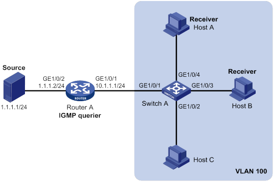
Configuration procedure
1. Assign an IP address and subnet mask to each interface, as shown in Figure 12. (Details not shown.)
2. Configure Router A:
# Enable IP multicast routing.
<RouterA> system-view
[RouterA] multicast routing
[RouterA-mrib] quit
# Enable IGMP on GigabitEthernet 1/0/1.
[RouterA] interface gigabitethernet 1/0/1
[RouterA-GigabitEthernet1/0/1] igmp enable
[RouterA-GigabitEthernet1/0/1] quit
# Enable PIM-DM on GigabitEthernet 1/0/2.
[RouterA] interface gigabitethernet 1/0/2
[RouterA-GigabitEthernet1/0/2] pim dm
[RouterA-GigabitEthernet1/0/2] quit
3. Configure Switch A:
# Enable IGMP snooping globally.
<SwitchA> system-view
[SwitchA] igmp-snooping
[SwitchA-igmp-snooping] quit
# Create VLAN 100, and assign GigabitEthernet 1/0/1 through GigabitEthernet 1/0/4 to the VLAN.
[SwitchA] vlan 100
[SwitchA-vlan100] port gigabitethernet 1/0/1 to gigabitethernet 1/0/4
# Enable IGMP snooping, and enable dropping unknown multicast data for VLAN 100.
[SwitchA-vlan100] igmp-snooping enable
[SwitchA-vlan100] igmp-snooping drop-unknown
[SwitchA-vlan100] quit
# Configure a multicast group policy so that hosts in VLAN 100 can join only multicast group 224.1.1.1.
[SwitchA] acl basic 2001
[SwitchA-acl-ipv4-basic-2001] rule permit source 224.1.1.1 0
[SwitchA-acl-ipv4-basic-2001] quit
[SwitchA] igmp-snooping
[SwitchA-igmp-snooping] group-policy 2001 vlan 100
[SwitchA-igmp-snooping] quit
# Configure GigabitEthernet 1/0/3 and GigabitEthernet 1/0/4 as simulated member hosts of multicast group 224.1.1.1.
[SwitchA] interface gigabitethernet 1/0/3
[SwitchA-GigabitEthernet1/0/3] igmp-snooping host-join 224.1.1.1 vlan 100
[SwitchA-GigabitEthernet1/0/3] quit
[SwitchA] interface gigabitethernet 1/0/4
[SwitchA-GigabitEthernet1/0/4] igmp-snooping host-join 224.1.1.1 vlan 100
[SwitchA-GigabitEthernet1/0/4] quit
Verifying the configuration
# Send IGMP reports from Host A and Host B to join multicast groups 224.1.1.1 and 224.2.2.2. (Details not shown.)
# Display dynamic IGMP snooping group entries for VLAN 100 on Switch A.
[SwitchA] display igmp-snooping group vlan 100
Total 1 entries.
VLAN 100: Total 1 entries.
(0.0.0.0, 224.1.1.1)
Host slots (0 in total):
Host ports (2 in total):
GE1/0/3 (00:03:23)
GE1/0/4 (00:04:10)
The output shows the following information:
· Host A and Host B have joined multicast group 224.1.1.1 through the member ports GigabitEthernet 1/0/4 and GigabitEthernet 1/0/3 on Switch A, respectively.
· Host A and Host B have failed to join multicast group 224.2.2.2.
Static port configuration example
Network requirements
As shown in Figure 13:
· Router A runs IGMPv2 and acts as the IGMP querier. Switch A, Switch B, and Switch C run IGMPv2 snooping.
· Host A and host C are permanent receivers of multicast group 224.1.1.1.
Configure static ports to meet the following requirements:
· To enhance the reliability of multicast traffic transmission, configure GigabitEthernet 1/0/3 and GigabitEthernet 1/0/5 on Switch C as static member ports for multicast group 224.1.1.1.
· Suppose the STP runs on the network. To avoid data loops, the forwarding path from Switch A to Switch C is blocked. Multicast data flows to the receivers attached to Switch C only along the path of Switch A—Switch B—Switch C. When this path is blocked, a minimum of one IGMP query-response cycle must be completed before multicast data flows to the receivers along the path of Switch A—Switch C. In this case, the multicast delivery is interrupted during the process. For more information about the STP, see Layer 2—LAN Switching Configuration Guide.
Configure GigabitEthernet 1/0/3 on Switch A as a static router port. Then, multicast data can flow to the receivers nearly uninterruptedly along the path of Switch A—Switch C when the path of Switch A—Switch B—Switch C is blocked.
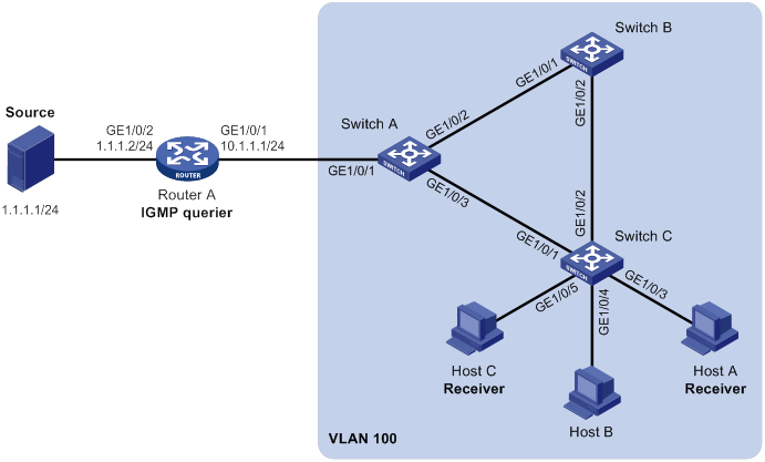
Configuration procedure
1. Assign an IP address and subnet mask to each interface, as shown in Figure 13. (Details not shown.)
2. Configure Router A:
# Enable IP multicast routing.
<RouterA> system-view
[RouterA] multicast routing
[RouterA-mrib] quit
# Enable IGMP on GigabitEthernet 1/0/1.
[RouterA] interface gigabitethernet 1/0/1
[RouterA-GigabitEthernet1/0/1] igmp enable
[RouterA-GigabitEthernet1/0/1] quit
# Enable PIM-DM on GigabitEthernet 1/0/2.
[RouterA] interface gigabitethernet 1/0/2
[RouterA-GigabitEthernet1/0/2] pim dm
[RouterA-GigabitEthernet1/0/2] quit
3. Configure Switch A:
# Enable IGMP snooping globally.
<SwitchA> system-view
[SwitchA] igmp-snooping
[SwitchA-igmp-snooping] quit
# Create VLAN 100, and assign GigabitEthernet 1/0/1 through GigabitEthernet 1/0/3 to the VLAN.
[SwitchA] vlan 100
[SwitchA-vlan100] port gigabitethernet 1/0/1 to gigabitethernet 1/0/3
# Enable IGMP snooping for VLAN 100.
[SwitchA-vlan100] igmp-snooping enable
[SwitchA-vlan100] quit
# Configure GigabitEthernet 1/0/3 as a static router port.
[SwitchA] interface gigabitethernet 1/0/3
[SwitchA-GigabitEthernet1/0/3] igmp-snooping static-router-port vlan 100
[SwitchA-GigabitEthernet1/0/3] quit
4. Configure Switch B:
# Enable IGMP snooping globally.
<SwitchB> system-view
[SwitchB] igmp-snooping
[SwitchB-igmp-snooping] quit
# Create VLAN 100, and assign GigabitEthernet 1/0/1 and GigabitEthernet 1/0/2 to the VLAN.
[SwitchB] vlan 100
[SwitchB-vlan100] port gigabitethernet 1/0/1 gigabitethernet 1/0/2
# Enable IGMP snooping for VLAN 100.
[SwitchB-vlan100] igmp-snooping enable
[SwitchB-vlan100] quit
5. Configure Switch C:
# Enable IGMP snooping globally.
<SwitchC> system-view
[SwitchC] igmp-snooping
[SwitchC-igmp-snooping] quit
# Create VLAN 100, and assign GigabitEthernet 1/0/1 through GigabitEthernet 1/0/5 to the VLAN.
[SwitchC] vlan 100
[SwitchC-vlan100] port gigabitethernet 1/0/1 to gigabitethernet 1/0/5
# Enable IGMP snooping for VLAN 100.
[SwitchC-vlan100] igmp-snooping enable
[SwitchC-vlan100] quit
# Configure GigabitEthernet 1/0/3 and GigabitEthernet 1/0/5 as static member ports for the multicast group 224.1.1.1.
[SwitchC] interface gigabitethernet 1/0/3
[SwitchC-GigabitEthernet1/0/3] igmp-snooping static-group 224.1.1.1 vlan 100
[SwitchC-GigabitEthernet1/0/3] quit
[SwitchC] interface gigabitethernet 1/0/5
[SwitchC-GigabitEthernet1/0/5] igmp-snooping static-group 224.1.1.1 vlan 100
[SwitchC-GigabitEthernet1/0/5] quit
Verifying the configuration
# Display static router port information for VLAN 100 on Switch A.
[SwitchA] display igmp-snooping static-router-port vlan 100
VLAN 100:
Router slots (0 in total):
Router ports (1 in total):
GE1/0/3
The output shows that GigabitEthernet 1/0/3 on Switch A has become a static router port.
# Display static IGMP snooping group entries for VLAN 100 on Switch C.
[SwitchC] display igmp-snooping static-group vlan 100
Total 1 entries.
VLAN 100: Total 1 entries.
(0.0.0.0, 224.1.1.1)
Host slots (0 in total):
Host ports (2 in total):
GE1/0/3
GE1/0/5
The output shows that GigabitEthernet 1/0/3 and GigabitEthernet 1/0/5 on Switch C have become static member ports of multicast group 224.1.1.1.
IGMP snooping querier configuration example
Network requirements
As shown in Figure 14:
· The network is a Layer 2-only network.
· Source 1 and Source 2 send multicast data to multicast groups 224.1.1.1 and 225.1.1.1, respectively.
· Host A and Host C are receivers of multicast group 224.1.1.1, and Host B and Host D are receivers of multicast group 225.1.1.1.
· All host receivers run IGMPv2, and all switches run IGMPv2 snooping. Switch A (which is close to the multicast sources) acts as the IGMP snooping querier.
Configure the switches to meet the following requirements:
· To prevent the switches from flooding unknown data in the VLAN, enable all the switches to drop unknown multicast data.
· A switch does not mark a port that receives an IGMP query with source IP address 0.0.0.0 as a dynamic router port. This adversely affects the establishment of Layer 2 forwarding entries and multicast traffic forwarding. To avoid this, configure the source IP address of IGMP queries as a non-zero IP address.
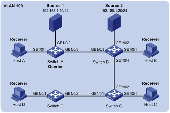
Configuration procedure
1. Configure Switch A:
# Enable IGMP snooping globally.
[SwitchA] igmp-snooping
[SwitchA-igmp-snooping] quit
# Create VLAN 100, and assign GigabitEthernet 1/0/1 through GigabitEthernet 1/0/3 to the VLAN.
[SwitchA-vlan100] port gigabitethernet 1/0/1 to gigabitethernet 1/0/3
# Enable IGMP snooping, and enable dropping unknown multicast data for VLAN 100.
[SwitchA-vlan100] igmp-snooping enable
[SwitchA-vlan100] igmp-snooping drop-unknown
# Configure Switch A as the IGMP snooping querier.
[SwitchA-vlan100] igmp-snooping querier
[SwitchA-vlan100] quit
# In VLAN 100, specify 192.168.1.1 as the source IP address of IGMP general queries.
[SwitchA-vlan100] igmp-snooping general-query source-ip 192.168.1.1
# In VLAN 100, specify 192.168.1.1 as the source IP address of IGMP group-specific queries.
[SwitchA-vlan100] igmp-snooping special-query source-ip 192.168.1.1
[SwitchA-vlan100] quit
2. Configure Switch B:
# Enable IGMP snooping globally.
[SwitchB] igmp-snooping
[SwitchB-igmp-snooping] quit
# Create VLAN 100, and assign GigabitEthernet 1/0/1 through GigabitEthernet 1/0/4 to the VLAN.
[SwitchB-vlan100] port gigabitethernet 1/0/1 to gigabitethernet 1/0/4
# Enable IGMP snooping, and enable dropping unknown multicast data for VLAN 100.
[SwitchB-vlan100] igmp-snooping enable
[SwitchB-vlan100] igmp-snooping drop-unknown
[SwitchB-vlan100] quit
3. Configure Switch C:
# Enable IGMP snooping globally.
[SwitchC] igmp-snooping
[SwitchC-igmp-snooping] quit
# Create VLAN 100, and assign GigabitEthernet 1/0/1 through GigabitEthernet 1/0/3 to the VLAN.
[SwitchC-vlan100] port gigabitethernet 1/0/1 to gigabitethernet 1/0/3
# Enable IGMP snooping, and enable dropping unknown multicast data for VLAN 100.
[SwitchC-vlan100] igmp-snooping enable
[SwitchC-vlan100] igmp-snooping drop-unknown
[SwitchC-vlan100] quit
4. Configure Switch D:
# Enable IGMP snooping globally.
[SwitchD] igmp-snooping
[SwitchD-igmp-snooping] quit
# Create VLAN 100, and assign GigabitEthernet 1/0/1 and GigabitEthernet 1/0/2 to the VLAN.
[SwitchD-vlan100] port gigabitethernet 1/0/1 to gigabitethernet 1/0/2
# Enable IGMP snooping, and enable dropping unknown multicast data for VLAN 100.
[SwitchD-vlan100] igmp-snooping enable
[SwitchD-vlan100] igmp-snooping drop-unknown
[SwitchD-vlan100] quit
Verifying the configuration
# Display statistics for IGMP messages and PIMv2 hello messages learned through IGMP snooping on Switch B.
[SwitchB] display igmp-snooping statistics
Received IGMP general queries: 3
Received IGMPv1 reports: 0
Received IGMPv2 reports: 12
Received IGMP leaves: 0
Received IGMPv2 specific queries: 0
Sent IGMPv2 specific queries: 0
Received IGMPv3 reports: 0
Received IGMPv3 reports with right and wrong records: 0
Received IGMPv3 specific queries: 0
Received IGMPv3 specific sg queries: 0
Sent IGMPv3 specific queries: 0
Sent IGMPv3 specific sg queries: 0
Received PIMv2 hello: 0
Received error IGMP messages: 0
The output shows that all switches except Switch A can receive the IGMP general queries after Switch A acts as the IGMP snooping querier.
Troubleshooting IGMP snooping
Layer 2 multicast forwarding cannot function
Symptom
Layer 2 multicast forwarding cannot function on the Layer 2 device.
Solution
To resolve the problem:
1. Use the display igmp-snooping command to display IGMP snooping status.
2. If IGMP snooping is not enabled, use the igmp-snooping command in system view to enable IGMP snooping globally. Then, use the igmp-snooping enable command in VLAN view to enable IGMP snooping for the VLAN.
3. If IGMP snooping is enabled globally but not enabled for the VLAN, use the igmp-snooping enable command in VLAN view to enable IGMP snooping for the VLAN.
4. If the problem persists, contact H3C Support.
Multicast group policy does not work
Symptom
Hosts can receive multicast data for multicast groups that are not permitted by the multicast group policy.
Solution
To resolve the problem:
1. Use the display acl command to verify that the configured ACL meets the multicast group policy requirements.
2. Use the display this command in IGMP-snooping view or in a corresponding interface view to verify that the correct multicast group policy has been applied. If it has not been applied, use the group-policy or igmp-snooping group-policy command to apply the correct multicast group policy.
3. Use the display igmp-snooping command to verify that dropping unknown multicast data is enabled. If it is not, use the igmp-snooping drop-unknown command to enable dropping unknown multicast data.
4. If the problem persists, contact H3C Support.
Configuring multicast routing and forwarding
Overview
The following tables are involved in multicast routing and forwarding:
· Multicast routing table of each multicast routing protocol, such as the PIM routing table.
· General multicast routing table that summarizes multicast routing information generated by different multicast routing protocols. The multicast routing information from multicast sources to multicast groups are stored in a set of (S, G) routing entries.
· Multicast forwarding table that guides multicast forwarding. The optimal routing entries in the multicast routing table are added to the multicast forwarding table.
RPF check mechanism
A multicast routing protocol uses reverse path forwarding (RPF) check to ensure the multicast data delivery along the correct path and to avoid data loops.
RPF check process
A multicast router performs the RPF check on a multicast packet as follows:
1. The router chooses an optimal route back to the packet source separately from the unicast, MBGP, and static multicast routing tables.
The term "packet source" means different things in different situations:
? For a packet that travels along the SPT, the packet source is the multicast source.
? For a packet that travels along the RPT, the packet source is the RP.
? For a bootstrap message originated from the BSR, the packet source is the BSR.
For more information about the concepts of SPT, RPT, source-side RPT, RP, and BSR, see "Configuring PIM."
2. The router selects one of the three optimal routes as the RPF route as follows:
? If the router uses the longest prefix match principle, the route with the highest subnet mask becomes the RPF route. If the routes have the same mask, the route with the highest route preference becomes the RPF route. If the routes have the same route preference, the unicast route becomes the RPF route.
For more information about the route preference, see Layer 3—IP Routing Configuration Guide.
? If the router does not use the longest prefix match principle, the route with the highest route preference becomes the RPF route. If the routes have the same preference, the unicast route becomes the RPF route.
The RPF route contains the RPF interface and RPF neighbor information.
? If the RPF route is a unicast route or MBGP route, the outgoing interface is the RPF interface and the next hop is the RPF neighbor.
? If the RPF route is a static multicast route, the RPF interface and RPF neighbor are specified in the route.
3. The router checks whether the packet arrived at the RPF interface. If yes, the RPF check succeeds and the packet is forwarded. If not, the RPF check fails and the packet is discarded.
RPF check implementation in multicast
Implementing an RPF check on each received multicast packet brings a big burden to the router. The use of a multicast forwarding table is the solution to this issue. When the router creates a multicast forwarding entry for an (S, G) packet, it sets the RPF interface of the packet as the incoming interface of the (S, G) entry. After the router receives another (S, G) packet, it looks up the multicast forwarding table for a matching (S, G) entry.
· If no match is found, the router first determines the RPF route back to the packet source and the RPF interface. Then, it creates a forwarding entry with the RPF interface as the incoming interface and makes the following judgments:
? If the receiving interface is the RPF interface, the RPF check succeeds and the router forwards the packet out of all the outgoing interfaces.
? If the receiving interface is not the RPF interface, the RPF check fails and the router discards the packet.
· If a match is found and the matching forwarding entry contains the receiving interface, the router forwards the packet out of all the outgoing interfaces.
· If a match is found but the matching forwarding entry does not contain the receiving interface, the router determines the RPF route back to the packet source. Then, the router performs one of the following actions:
? If the RPF interface is the incoming interface, it means that the forwarding entry is correct but the packet traveled along a wrong path. The packet fails the RPF check, and the router discards the packet.
? If the RPF interface is not the incoming interface, it means that the forwarding entry has expired. The router replaces the incoming interface with the RPF interface and matches the receiving interface against the RPF interface. If the receiving interface is the RPF interface, the router forwards the packet out of all outgoing interfaces. Otherwise, it discards the packet.

As shown in Figure 15, assume that unicast routes are available on the network, MBGP is not configured, and no static multicast routes have been configured on Router C. Multicast packets travel along the SPT from the multicast source to the receivers. The multicast forwarding table on Router C contains the (S, G) entry, with GigabitEthernet 1/0/2 as the incoming interface.
· If a multicast packet arrives at Router C on GigabitEthernet 1/0/2, the receiving interface is the incoming interface of the (S, G) entry. Router C forwards the packet out of all outgoing interfaces.
· If a multicast packet arrives at Router C on GigabitEthernet 1/0/1, the receiving interface is not the incoming interface of the (S, G) entry. Router C searches its unicast routing table and finds that the outgoing interface to the source (the RPF interface) is GigabitEthernet 1/0/2. In this case, the (S, G) entry is correct, but the packet traveled along a wrong path. The packet fails the RPF check and Router C discards the packet.
Static multicast routes
Depending on the application environment, a static multicast route can change an RPF route or create an RPF route.
Changing an RPF route
Typically, the topology structure of a multicast network is the same as that of a unicast network, and multicast traffic follows the same transmission path as unicast traffic does. You can configure a static multicast route for a multicast source to change the RPF route. As a result, the router creates a transmission path for multicast traffic that is different from the transmission path for unicast traffic.
Figure 16 Changing an RPF route
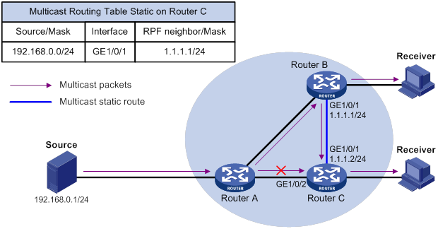
As shown in Figure 16, when no static multicast route is configured, Router C's RPF neighbor on the path back to the source is Router A. The multicast data from the source travels through Router A to Router C. You can configure a static multicast route on Router C and specify Router B as Router C's RPF neighbor on the path back to the source. The multicast data from the source travels along the path: Router A to Router B and then to Router C.
Creating an RPF route
When a unicast route is blocked, multicast forwarding might be stopped due to lack of an RPF route. You can configure a static multicast route to create an RPF route. In this way, a multicast routing entry is created to guide multicast forwarding.
Figure 17 Creating an RPF route
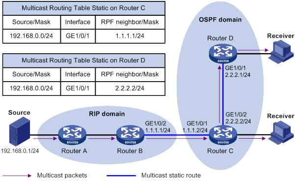
As shown in Figure 17, the RIP domain and the OSPF domain are unicast isolated from each other. For the receiver hosts in the OSPF domain to receive multicast packets from the multicast source in the RIP domain, you must configure Router C and Router D as follows:
· On Router C, configure a static multicast route for the multicast source and specify Router B as the RPF neighbor.
· On Router D, configure a static multicast route for the multicast source and specify Router C as the RPF neighbor.
|
|
NOTE: A static multicast route is effective only on the multicast router on which it is configured, and will not be advertised throughout the network or redistributed to other routers. |
Multicast forwarding across unicast subnets
Routers forward the multicast data from a multicast source hop by hop along the forwarding tree, but some routers might not support multicast protocols in a network. When the multicast data is forwarded to a router that does not support IP multicast, the forwarding path is blocked. In this case, you can enable multicast forwarding across two unicast subnets by establishing a tunnel between the routers at the edges of the two unicast subnets.
Figure 18 Multicast data transmission through a tunnel
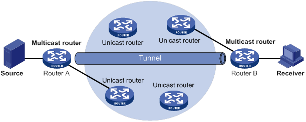
As shown in Figure 18, a tunnel is established between the multicast routers Router A and Router B. Router A encapsulates the multicast data in unicast IP packets, and forwards them to Router B across the tunnel through unicast routers. Then, Router B strips off the unicast IP header and continues to forward the multicast data to the receiver.
To use this tunnel only for multicast traffic, configure the tunnel as the outgoing interface only for multicast routes.
Compatibility information
Feature and hardware compatibility
The following matrix shows the feature and hardware compatibility:
|
Hardware |
Multicast routing and forwarding compatibility |
|
MSR810/810-W/810-W-DB/810-LM/810-W-LM/810-10-PoE/810-LM-HK/810-W-LM-HK |
Yes |
|
MSR810-LMS/810-LUS |
No |
|
MSR2600-6-X1/2600-10-X1 |
Yes |
|
MSR 2630 |
Yes |
|
MSR3600-28/3600-51 |
Yes |
|
MSR3600-28-SI/3600-51-SI |
No |
|
MSR3610-X1/3610-X1-DP/3610-X1-DC/3610-X1-DP-DC |
Yes |
|
MSR 3610/3620/3620-DP/3640/3660 |
Yes |
|
MSR5620/5660/5680 |
Yes |
|
Hardware |
Multicast routing and forwarding compatibility |
|
MSR810-LM-GL |
Yes |
|
MSR810-W-LM-GL |
Yes |
|
MSR830-6EI-GL |
Yes |
|
MSR830-10EI-GL |
Yes |
|
MSR830-6HI-GL |
Yes |
|
MSR830-10HI-GL |
Yes |
|
MSR2600-6-X1-GL |
Yes |
|
MSR3600-28-SI-GL |
No |
Command and hardware compatibility
Commands and descriptions for centralized devices apply to the following routers:
· MSR810/810-W/810-W-DB/810-LM/810-W-LM/810-10-PoE/810-LM-HK/810-W-LM-HK.
· MSR2600-6-X1/2600-10-X1.
· MSR 2630.
· MSR3600-28/3600-51.
· MSR3610-X1/3610-X1-DP/3610-X1-DC/3610-X1-DP-DC.
· MSR 3610/3620/3620-DP/3640/3660.
· MSR810-LM-GL/810-W-LM-GL/830-6EI-GL/830-10EI-GL/830-6HI-GL/830-10HI-GL/2600-6-X1-GL.
Commands and descriptions for distributed devices apply to the following routers:
· MSR5620.
· MSR 5660.
· MSR 5680.
Multicast routing and forwarding configuration task list
|
Tasks at a glance |
|
(Required.) Enabling IP multicast routing |
|
(Optional.) Configuring multicast routing and forwarding: · (Optional.) Configuring static multicast routes · (Optional.) Specifying the longest prefix match principle · (Optional.) Configuring multicast load splitting · (Optional.) Configuring a multicast forwarding boundary · (Optional.) Configuring static multicast MAC address entries |
|
|
NOTE: The device can route and forward multicast data only through the primary IP addresses of interfaces, rather than their secondary addresses or unnumbered IP addresses. For more information about primary and secondary IP addresses, and IP unnumbered, see Layer 3—IP Services Configuration Guide. |
Enabling IP multicast routing
Enable IP multicast routing before you configure any Layer 3 multicast functionality on the public network or VPN instance.
To enable IP multicast routing:
|
Step |
Command |
Remarks |
|
1. Enter system view. |
system-view |
N/A |
|
2. Enable IP multicast routing and enter MRIB view. |
multicast routing [ vpn-instance vpn-instance-name ] |
By default, IP multicast routing is disabled. |
Configuring multicast routing and forwarding
Before you configure multicast routing and forwarding, complete the following tasks:
· Configure a unicast routing protocol so that all devices in the domain can interoperate at the network layer.
· Enable PIM-DM or PIM-SM.
Configuring static multicast routes
To configure a static multicast route for a given multicast source, you can specify an RPF interface or an RPF neighbor for the multicast traffic from that source.
To configure a static multicast route:
|
Step |
Command |
Remarks |
|
1. Enter system view. |
system-view |
N/A |
|
2. Configure a static multicast route. |
ip rpf-route-static [ vpn-instance vpn-instance-name ] source-address { mask-length | mask } { rpf-nbr-address | interface-type interface-number } [ preference preference ] |
By default, no static multicast routes exist. |
|
3. (Optional.) Delete static multicast routes. |
·
Delete a specific static multicast route: ·
Delete all static multicast routes: |
N/A |
Specifying the longest prefix match principle
You can enable the device to use the longest prefix match principle for RPF route selection. For more information about RPF route selection, see "RPF check process."
To specify the longest prefix match principle:
|
Step |
Command |
Remarks |
|
1. Enter system view. |
system-view |
N/A |
|
2. Enter MRIB view. |
multicast routing [ vpn-instance vpn-instance-name ] |
N/A |
|
3. Specify the longest prefix match principle. |
longest-match |
By default, the route preference principle is used. |
Configuring multicast load splitting
You can enable the device to split multiple data flows on a per-source basis or on a per-source-and-group basis. This optimizes the traffic delivery.
To configure multicast load splitting:
|
Step |
Command |
Remarks |
|
1. Enter system view. |
system-view |
N/A |
|
2. Enter MRIB view. |
multicast routing [ vpn-instance vpn-instance-name ] |
N/A |
|
3. Configure multicast load splitting. |
load-splitting { source | source-group } |
By default, multicast load splitting is disabled. This command does not take effect on BIDIR-PIM. |
Configuring a multicast forwarding boundary
You can configure an interface as a multicast forwarding boundary for a multicast group range. The interface cannot receive or forward multicast packets for the group range.
|
|
TIP: You do not need to enable IP multicast routing before this configuration. |
To configure a multicast forwarding boundary:
|
Step |
Command |
Remarks |
|
1. Enter system view. |
system-view |
N/A |
|
2. Enter interface view. |
interface interface-type interface-number |
N/A |
|
3. Configure the interface as a multicast forwarding boundary for a multicast group range. |
multicast boundary group-address { mask-length | mask } |
By default, an interface is not a multicast forwarding boundary. |
Configuring static multicast MAC address entries
In Layer 2 multicast, multicast MAC address entries can be dynamically created or added through Layer 2 multicast protocols (such as IGMP snooping). You can also manually configure static multicast MAC address entries by binding multicast MAC addresses and ports to control the destination ports of the multicast data.
|
|
TIP: · You do not need to enable IP multicast routing before this configuration. · The multicast MAC address that can be manually configured in the multicast MAC address entry must be unused. (A multicast MAC address is the MAC address in which the least significant bit of the most significant octet is 1.) |
You can configure static multicast MAC address entries on the specified interfaces in system view or on the current interface in interface view.
To configure a static multicast MAC address entry in system view:
|
Step |
Command |
Remarks |
|
1. Enter system view. |
system-view |
N/A |
|
2. Configure a static multicast MAC address entry. |
mac-address multicast mac-address interface interface-list vlan vlan-id |
By default, no static multicast MAC address entries exist. |
To configure a static multicast MAC address entry in interface view:
|
Step |
Command |
Remarks |
|
1. Enter system view. |
system-view |
N/A |
|
2. Enter Layer 2 Ethernet interface/Layer 2 aggregate interface view. |
interface interface-type interface-number |
N/A |
|
3. Configure a static multicast MAC address entry. |
mac-address multicast mac-address vlan vlan-id |
By default, no static multicast MAC address entries exist. |
Displaying and maintaining multicast routing and forwarding
|
|
CAUTION: The reset commands might cause multicast data transmission failures. |
Execute display commands in any view and reset commands in user view.
|
Task |
Command |
|
Display static multicast MAC address entries. |
display mac-address [ mac-address [ vlan vlan-id ] | [ multicast ] [ vlan vlan-id ] [ count ] ] |
|
Display information about the interfaces maintained by the MRIB. |
display mrib [ vpn-instance vpn-instance-name ] interface [ interface-type interface-number ] |
|
Display multicast boundary information. |
display multicast [ vpn-instance vpn-instance-name ] boundary [ group-address [ mask-length | mask ] ] [ interface interface-type interface-number ] |
|
Display multicast fast forwarding entries (centralized devices in standalone mode). |
|
|
Display multicast fast forwarding entries (distributed devices in standalone mode/centralized devices in IRF mode). |
|
|
Display multicast fast forwarding entries (distributed devices in IRF mode). |
|
|
Display DF information (centralized devices in standalone mode). |
display multicast [ vpn-instance vpn-instance-name ] forwarding df-info [ rp-address ] [ verbose ] |
|
Display DF information (distributed devices in standalone mode/centralized devices in IRF mode). |
display multicast [ vpn-instance vpn-instance-name ] forwarding df-info [ rp-address ] [ verbose ] [ slot slot-number ] |
|
Display DF information (distributed devices in IRF mode). |
display multicast [ vpn-instance vpn-instance-name ] forwarding df-info [ rp-address ] [ verbose ] [ chassis chassis-number slot slot-number ] |
|
Display statistics for multicast forwarding events (centralized devices in standalone mode). |
display multicast [ vpn-instance vpn-instance-name ] forwarding event |
|
Display statistics for multicast forwarding events (distributed devices in standalone mode/centralized devices in IRF mode). |
display multicast [ vpn-instance vpn-instance-name ] forwarding event [ slot slot-number ] |
|
Display statistics for multicast forwarding events (distributed devices in IRF mode). |
display multicast [ vpn-instance vpn-instance-name ] forwarding event [ chassis chassis-number slot slot-number ] |
|
Display multicast forwarding entries (centralized devices in standalone mode). |
display multicast [ vpn-instance vpn-instance-name ] forwarding-table [ source-address [ mask { mask-length | mask } ] | group-address [ mask { mask-length | mask } ] | incoming-interface interface-type interface-number | outgoing-interface { exclude | include | match } interface-type interface-number | statistics ] * |
|
Display multicast forwarding entries (distributed devices in standalone mode/centralized devices in IRF mode). |
display multicast [ vpn-instance vpn-instance-name ] forwarding-table [ source-address [ mask { mask-length | mask } ] | group-address [ mask { mask-length | mask } ] | incoming-interface interface-type interface-number | outgoing-interface { exclude | include | match } interface-type interface-number | slot slot-number | statistics ] * |
|
Display multicast forwarding entries (distributed devices in IRF mode). |
display multicast [ vpn-instance vpn-instance-name ] forwarding-table [ source-address [ mask { mask-length | mask } ] | group-address [ mask { mask-length | mask } ] | chassis chassis-number slot slot-number | incoming-interface interface-type interface-number | outgoing-interface { exclude | include | match } interface-type interface-number | statistics ] * |
|
Display information about the DF list in the multicast forwarding table (centralized devices in standalone mode). |
display multicast [ vpn-instance vpn-instance-name ] forwarding-table df-list [ group-address ] [ verbose ] |
|
Display information about the DF list in the multicast forwarding table (distributed devices in standalone mode/centralized devices in IRF mode). |
display multicast [ vpn-instance vpn-instance-name ] forwarding-table df-list [ group-address ] [ verbose ] [ slot slot-number ] |
|
Display information about the DF list in the multicast forwarding table (distributed devices in IRF mode). |
display multicast [ vpn-instance vpn-instance-name ] forwarding-table df-list [ group-address ] [ verbose ] [ chassis chassis-number slot slot-number ] |
|
Display multicast routing entries. |
display multicast [ vpn-instance vpn-instance-name ] routing-table [ source-address [ mask { mask-length | mask } ] | group-address [ mask { mask-length | mask } ] | incoming-interface interface-type interface-number | outgoing-interface { exclude | include | match } interface-type interface-number ] * |
|
Display static multicast routing entries. |
display multicast [ vpn-instance vpn-instance-name ] routing-table static [ source-address { mask-length | mask } ] |
|
Display RPF information for a multicast source. |
display multicast [ vpn-instance vpn-instance-name ] rpf-info source-address [ group-address ] |
|
Clear multicast fast forwarding entries (centralized devices in standalone mode). |
|
|
Clear multicast fast forwarding entries (distributed devices in standalone mode/centralized devices in IRF mode). |
|
|
Clear multicast fast forwarding entries (distributed devices in IRF mode). |
|
|
Clear statistics for multicast forwarding events. |
reset multicast [ vpn-instance vpn-instance-name ] forwarding event |
|
Clear multicast forwarding entries. |
reset multicast [ vpn-instance vpn-instance-name ] forwarding-table { { source-address [ mask { mask-length | mask } ] | group-address [ mask { mask-length | mask } ] | incoming-interface { interface-type interface-number } } * | all } |
|
Clear multicast routing entries. |
reset multicast [ vpn-instance vpn-instance-name ] routing-table { { source-address [ mask { mask-length | mask } ] | group-address [ mask { mask-length | mask } ] | incoming-interface interface-type interface-number } * | all } |
|
|
NOTE: · When you clear a multicast routing entry, the associated multicast forwarding entry is also cleared. · When you clear a multicast forwarding entry, the associated multicast routing entry is also cleared. |
Multicast routing and forwarding configuration examples
Changing an RPF route
Network requirements
As shown in Figure 19:
· PIM-DM runs on the network.
· All routers on the network support multicast.
· Router A, Router B, and Router C run OSPF.
· Typically, the receiver host can receive the multicast data from Source through the path: Router A to Router B, which is the same as the unicast route.
Configure the routers so that the multicast data from Source travels to the receiver along the following path: Router A to Router C to Router B. This path is different from the unicast route.
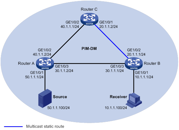
Configuration procedure
1. Assign an IP address and subnet mask for each interface, as shown in Figure 19. (Details not shown.)
2. Configure OSPF on the routers in the PIM-DM domain. (Details not shown.)
3. Enable IP multicast routing, and enable IGMP and PIM-DM:
# On Router B, enable IP multicast routing.
<RouterB> system-view
[RouterB] multicast routing
[RouterB-mrib] quit
# Enable IGMP on the receiver-side interface (GigabitEthernet 1/0/1).
[RouterB] interface gigabitethernet 1/0/1
[RouterB-GigabitEthernet1/0/1] igmp enable
[RouterB-GigabitEthernet1/0/1] quit
# Enable PIM-DM on the other interfaces.
[RouterB] interface gigabitethernet 1/0/2
[RouterB-GigabitEthernet1/0/2] pim dm
[RouterB-GigabitEthernet1/0/2] quit
[RouterB] interface gigabitethernet 1/0/3
[RouterB-GigabitEthernet1/0/3] pim dm
[RouterB-GigabitEthernet1/0/3] quit
# On Router A, enable IP multicast routing.
<RouterA> system-view
[RouterA] multicast routing
[RouterA-mrib] quit
# Enable PIM-DM on each interface.
[RouterA] interface gigabitethernet 1/0/1
[RouterA-GigabitEthernet1/0/1] pim dm
[RouterA-GigabitEthernet1/0/1] quit
[RouterA] interface gigabitethernet 1/0/2
[RouterA-GigabitEthernet1/0/2] pim dm
[RouterA-GigabitEthernet1/0/2] quit
[RouterA] interface gigabitethernet 1/0/3
[RouterA-GigabitEthernet1/0/3] pim dm
[RouterA-GigabitEthernet1/0/3] quit
# Enable IP multicast routing and PIM-DM on Router C in the same way Router A is configured. (Details not shown.)
4. Display RPF information for Source on Router B.
[RouterB] display multicast rpf-info 50.1.1.100
RPF information about source 50.1.1.100:
RPF interface: GigabitEthernet1/0/3, RPF neighbor: 30.1.1.2
Referenced route/mask: 50.1.1.0/24
Referenced route type: igp
Route selection rule: preference-preferred
Load splitting rule: disable
The output shows that the current RPF route on Router B is contributed by a unicast routing protocol and the RPF neighbor is Router A.
5. Configure a static multicast route on Router B and specify Router C as its RPF neighbor to Source.
[RouterB] ip rpf-route-static 50.1.1.100 24 20.1.1.2
Verifying the configuration
# Display RPF information for Source on Router B.
[RouterB] display multicast rpf-info 50.1.1.100
RPF information about source 50.1.1.100:
RPF interface: GigabitEthernet1/0/2, RPF neighbor: 20.1.1.2
Referenced route/mask: 50.1.1.0/24
Referenced route type: multicast static
Route selection rule: preference-preferred
Load splitting rule: disable
The output shows the following information:
· The RPF route on Router B is the configured static multicast route.
· The RPF neighbor of Router B is Router C.
Creating an RPF route
Network requirements
As shown in Figure 20:
· PIM-DM runs on the network.
· All routers on the network support IP multicast.
· Router B and Router C run OSPF, and have no unicast routes to Router A.
· Typically, the receiver host receives the multicast data from Source 1 in the OSPF domain.
Configure the routers so that the receiver host can receive multicast data from Source 2, which is outside the OSPF domain.
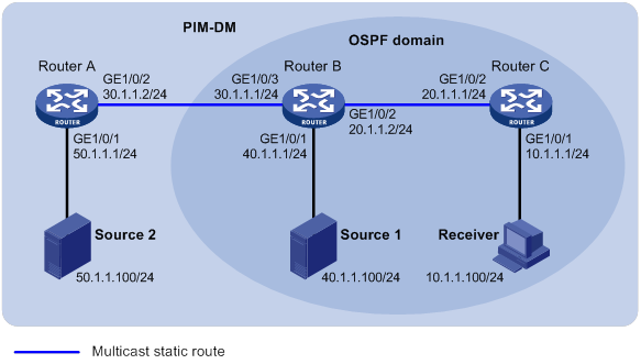
Configuration procedure
1. Assign an IP address and subnet mask for each interface, as shown in Figure 20. (Details not shown.)
2. Configure OSPF on Router B and Router C. (Details not shown.)
3. Enable IP multicast routing, and enable IGMP and PIM-DM:
# On Router C, enable IP multicast routing.
<RouterC> system-view
[RouterC] multicast routing
[RouterC-mrib] quit
# Enable IGMP on the receiver-side interface (GigabitEthernet 1/0/1).
[RouterC] interface gigabitethernet 1/0/1
[RouterC-GigabitEthernet1/0/1] igmp enable
[RouterC-GigabitEthernet1/0/1] quit
# Enable PIM-DM on GigabitEthernet 1/0/2.
[RouterC] interface gigabitethernet 1/0/2
[RouterC-GigabitEthernet1/0/2] pim dm
[RouterC-GigabitEthernet1/0/2] quit
# On Router A, enable IP multicast routing.
<RouterA> system-view
[RouterA] multicast routing
[RouterA-mrib] quit
# Enable PIM-DM on each interface.
[RouterA] interface gigabitethernet 1/0/1
[RouterA-GigabitEthernet1/0/1] pim dm
[RouterA-GigabitEthernet1/0/1] quit
[RouterA] interface gigabitethernet 1/0/2
[RouterA-GigabitEthernet1/0/2] pim dm
[RouterA-GigabitEthernet1/0/2] quit
# Enable IP multicast routing and PIM-DM on Router B in the same way Router A is configured. (Details not shown.)
4. Display RPF information for Source 2 on Router B and Router C.
[RouterB] display multicast rpf-info 50.1.1.100
[RouterC] display multicast rpf-info 50.1.1.100
No output is displayed because no RPF routes to Source 2 exist on Router B and Router C.
5. Configure a static multicast route:
# Configure a static multicast route on Router B and specify Router A as its RPF neighbor to Source 2.
[RouterB] ip rpf-route-static 50.1.1.100 24 30.1.1.2
# Configure a static multicast route on Router C and specify Router B as its RPF neighbor to Source 2.
[RouterC] ip rpf-route-static 50.1.1.100 24 20.1.1.2
Verifying the configuration
# Display RPF information for Source 2 on Router B.
[RouterB] display multicast rpf-info 50.1.1.100
RPF information about source 50.1.1.100:
RPF interface: GigabitEthernet1/0/3, RPF neighbor: 30.1.1.2
Referenced route/mask: 50.1.1.0/24
Referenced route type: multicast static
Route selection rule: preference-preferred
Load splitting rule: disable
# Display RPF information for Source 2 on Router C.
[RouterC] display multicast rpf-info 50.1.1.100
RPF information about source 50.1.1.100:
RPF interface: GigabitEthernet1/0/2, RPF neighbor: 20.1.1.2
Referenced route/mask: 50.1.1.0/24
Referenced route type: multicast static
Route selection rule: preference-preferred
Load splitting rule: disable
The output shows that the RPF routes to Source 2 exist on Router B and Router C. These RPF routes are the configured static multicast routes.
Multicast forwarding over a GRE tunnel
Network requirements
As shown in Figure 21:
· Multicast routing and PIM-DM are enabled on Router A and Router C. Router B does not support multicast.
· Router A, Router B, and Router C run OSPF. The source-side interface GigabitEthernet 1/0/1 on Router A does not run OSPF.
Configure a GRE tunnel so that the receiver host can receive the multicast data from Source.
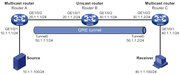
Configuration procedure
1. Assign an IP address and mask for each interface, as shown in Figure 21. (Details not shown.)
2. Configure OSPF on all the routers. Do not enable OSPF on GigabitEthernet 1/0/1 on Router A. (Details not shown.)
3. Configure a GRE tunnel:
# Create a GRE tunnel interface Tunnel 0 on Router A, and specify the tunnel mode as GRE/IPv4.
<RouterA> system-view
[RouterA] interface tunnel 0 mode gre
# Assign an IP address to interface Tunnel 0, and specify its source and destination addresses.
[RouterA-Tunnel0] ip address 50.1.1.1 24
[RouterA-Tunnel0] source 20.1.1.1
[RouterA-Tunnel0] destination 30.1.1.2
[RouterA-Tunnel0] quit
# Create a GRE tunnel interface Tunnel 0 on Router C, and specify the tunnel mode as GRE/IPv4.
<RouterC> system-view
[RouterC] interface tunnel 0 mode gre
# Assign an IP address to interface Tunnel 0, and specify its source and destination addresses.
[RouterC-Tunnel0] ip address 50.1.1.2 24
[RouterC-Tunnel0] source 30.1.1.2
[RouterC-Tunnel0] destination 20.1.1.1
[RouterC-Tunnel0] quit
4. Enable IP multicast routing, PIM-DM, and IGMP:
# On Router A, enable IP multicast routing.
[RouterA] multicast routing
[RouterA-mrib] quit
# Enable PIM-DM on each interface.
[RouterA] interface gigabitethernet 1/0/1
[RouterA-GigabitEthernet1/0/1] pim dm
[RouterA-GigabitEthernet1/0/1] quit
[RouterA] interface gigabitethernet 1/0/2
[RouterA-GigabitEthernet1/0/2] pim dm
[RouterA-GigabitEthernet1/0/2] quit
[RouterA] interface tunnel 0
[RouterA-Tunnel0] pim dm
[RouterA-Tunnel0] quit
# On Router C, enable IP multicast routing.
[RouterC] multicast routing
[RouterC-mrib] quit
# Enable IGMP on the receiver-side interface (GigabitEthernet 1/0/1).
[RouterC] interface gigabitethernet 1/0/1
[RouterC-GigabitEthernet1/0/1] igmp enable
[RouterC-GigabitEthernet1/0/1] quit
# Enable PIM-DM on other interfaces.
[RouterC] interface gigabitethernet 1/0/2
[RouterC-GigabitEthernet1/0/2] pim dm
[RouterC-GigabitEthernet1/0/2] quit
[RouterC] interface tunnel 0
[RouterC-Tunnel0] pim dm
[RouterC-Tunnel0] quit
5. On Router C, configure a static multicast route and specify Tunnel 0 on Router A as its RPF neighbor to Source.
[RouterC] ip rpf-route-static 10.1.1.0 24 50.1.1.1
Verifying the configuration
# Send an IGMP report from Receiver to join multicast group 225.1.1.1. (Details not shown.)
# Send multicast data from Source to multicast group 225.1.1.1. (Details not shown.)
# Display PIM routing entries on Router C.
[RouterC] display pim routing-table
Total 1 (*, G) entry; 1 (S, G) entry
(*, 225.1.1.1)
Protocol: pim-dm, Flag: WC
UpTime: 00:04:25
Upstream interface: NULL
Upstream neighbor: NULL
RPF prime neighbor: NULL
Downstream interface(s) information:
Total number of downstreams: 1
1: GigabitEthernet1/0/1
Protocol: igmp, UpTime: 00:04:25, Expires: -
(10.1.1.100, 225.1.1.1)
Protocol: pim-dm, Flag: ACT
UpTime: 00:06:14
Upstream interface: Tunnel0
Upstream neighbor: 50.1.1.1
RPF prime neighbor: 50.1.1.1
Downstream interface(s) information:
Total number of downstreams: 1
1: GigabitEthernet1/0/1
Protocol: pim-dm, UpTime: 00:04:25, Expires: -
The output shows that Router A is the RPF neighbor of Router C and the multicast data from Router A is delivered over the GRE tunnel to Router C.
Multicast forwarding over ADVPN tunnels
Network requirements
· An ADVPN tunnel is established between each spoke and hub.
· All hubs and spokes support IP multicast. PIM-SM runs on them, and NBMA runs on their ADVPN tunnel interfaces.
· OSPF runs on all hubs and spokes.
Configure the routers so that Spoke 1 can receive multicast data from the source.

Table 6 Interface and IP address assignment
|
Interface |
IP address |
Device |
Interface |
IP address |
|
|
Hub 1 |
Spoke 1 |
||||
|
Hub 1 |
Spoke 1 |
||||
|
Hub 1 |
|||||
|
Hub 2 |
GE1/0/1 |
100.1.1.2/24 |
Spoke 2 |
||
|
Hub 2 |
Tunnel1 |
192.168.0.2/24 |
|||
|
Hub 2 |
Loop0 |
2.2.2.2/32 |
|
|
|
Configuration procedure
1. Assign an IP address and subnet mask to each interface, as shown in Table 6. (Details not shown.)
a. Configure the VAM server:
# Create an ADVPN domain named abc.
[Server] vam server advpn-domain abc id 1
# Set the pre-shared key to 123456.
[Server-vam-server-domain-abc] pre-shared-key simple 123456
# Configure the VAM server not to authenticate VAM clients.
[Server-vam-server-domain-abc] authentication-method none
[Server-vam-server-domain-abc] server enable
[Server-vam-server-domain-abc] hub-group 0
# Specify private IPv4 addresses for hubs in hub group 0.
[Server-vam-server-domain-abc-hub-group-0] hub private-address 192.168.0.1
[Server-vam-server-domain-abc-hub-group-0] hub private-address 192.168.0.2
# Specify a private IPv4 address range for spokes in hub group 0.
[Server-vam-server-domain-abc-hub-group-0] spoke private-address range 192.168.0.0 192.168.0.255
[Server-vam-server-domain-abc-hub-group-0] quit
[Server-vam-server-domain-abc] quit
# Create a VAM client named hub1.
[Hub1] vam client name hub1
# Specify ADVPN domain abc for the VAM client.
[Hub1-vam-client-hub1] advpn-domain abc
[Hub1-vam-client-hub1] server primary ip-address 100.1.1.100
# Set the pre-shared key to 123456.
[Hub1-vam-client-hub1] pre-shared-key simple 123456
[Hub1-vam-client-hub1] client enable
# Create a VAM client named hub2.
[Hub2] vam client name hub2
# Specify ADVPN domain abc for the VAM client.
[Hub2-vam-client-hub2] advpn-domain abc
[Hub2-vam-client-hub2] server primary ip-address 100.1.1.100
# Set the pre-shared key to 123456.
[Hub2-vam-client-hub2] pre-shared-key simple 123456
[Hub2-vam-client-hub2] client enable
# Create a VAM client named Spoke1.
[Spoke1] vam client name Spoke1
# Specify ADVPN domain abc for the VAM client.
[Spoke1-vam-client-Spoke1] advpn-domain abc
[Spoke1-vam-client-Spoke1] server primary ip-address 100.1.1.100
# Set the pre-shared key to 123456.
[Spoke1-vam-client-Spoke1] pre-shared-key simple 123456
[Spoke1-vam-client-Spoke1] client enable
[Spoke1-vam-client-Spoke1] quit
# Create a VAM client named Spoke2.
[Spoke2] vam client name Spoke2
# Specify ADVPN domain abc for the VAM client.
[Spoke2-vam-client-Spoke2] advpn-domain abc
[Spoke2-vam-client-Spoke2] server primary ip-address 100.1.1.100
# Set the pre-shared key to 123456.
[Spoke2-vam-client-Spoke2] pre-shared-key simple 123456
[Spoke2-vam-client-Spoke2] client enable
[Spoke2-vam-client-Spoke2] quit
f. Configure ADVPN tunnel interfaces:
# On Hub 1, configure GRE-mode IPv4 ADVPN tunnel interface tunnel1.
[Hub1] interface tunnel 1 mode advpn gre
[Hub1-Tunnel1] ip address 192.168.0.1 24
[Hub1-Tunnel1] ospf network-type p2mp
[Hub1-Tunnel1] source gigabitethernet 1/0/1
[Hub1-Tunnel1] vam client hub1
[Hub1-Tunnel1] quit
# On Hub 2, configure GRE-mode IPv4 ADVPN tunnel interface tunnel1.
[Hub2] interface tunnel 1 mode advpn gre
[Hub2-Tunnel1] ip address 192.168.0.2 24
[Hub2-Tunnel1] ospf network-type p2mp
[Hub2-Tunnel1] source gigabitethernet 1/0/1
[Hub2-Tunnel1] vam client hub2
[Hub2-Tunnel1] quit
# On Spoke 1, configure GRE-mode IPv4 ADVPN tunnel interface tunnel1.
[Spoke1] interface tunnel 1 mode advpn gre
[Spoke1-Tunnel1] ip address 192.168.0.3 24
[Spoke1-Tunnel1] ospf network-type p2mp
[Spoke1-Tunnel1] source gigabitethernet 1/0/1
[Spoke1-Tunnel1] vam client Spoke1
[Spoke1-Tunnel1] quit
# On Spoke 2, configure GRE-mode IPv4 ADVPN tunnel interface tunnel1.
[Spoke2] interface tunnel 1 mode advpn gre
[Spoke2-Tunnel1] ip address 192.168.0.4 24
[Spoke2-Tunnel1] ospf network-type p2mp
[Spoke2-Tunnel1] source gigabitethernet 1/0/1
[Spoke2-Tunnel1] vam client Spoke2
[Spoke2-Tunnel1] quit
[Hub1] ospf
[Hub1-ospf-1] area 0.0.0.0
[Hub1-ospf-1-area-0.0.0.0] network 10.1.1.0 0.0.0.255
[Hub1-ospf-1-area-0.0.0.0] network 1.1.1.1 0.0.0.255
[Hub1-ospf-1-area-0.0.0.0] network 192.168.0.0 0.0.0.255
[Hub1-ospf-1-area-0.0.0.0] quit
[Hub1-ospf-1] quit
<Hub2> system-view
[Hub2] ospf
[Hub2-ospf-1] area 0.0.0.0
[Hub2-ospf-1-area-0.0.0.0] network 2.2.2.2 0.0.0.255
[Hub2-ospf-1-area-0.0.0.0] network 192.168.0.0 0.0.0.255
[Hub2-ospf-1-area-0.0.0.0] quit
[Hub2-ospf-1] quit
<Spoke1> system-view
[Spoke1] ospf
[Spoke1-ospf-1] area 0.0.0.0
[Spoke1-ospf-1-area-0.0.0.0] network 192.168.0.0 0.0.0.255
[Spoke1-ospf-1-area-0.0.0.0] network 20.1.1.0 0.0.0.255
[Spoke1-ospf-1-area-0.0.0.0] quit
[Spoke1-ospf-1] quit
<Spoke2> system-view
[Spoke2] ospf
[Spoke2-ospf-1] area 0.0.0.0
[Spoke2-ospf-1-area-0.0.0.0] network 192.168.0.0 0.0.0.255
[Spoke2-ospf-1-area-0.0.0.0] quit
[Spoke2-ospf-1] quit
# Enable IP multicast routing.
[Hub1] multicast routing
[Hub1-mrib] quit
# Enable PIM-SM on Loopback 0 and GigabitEthernet 1/0/2.
[Hub1] interface loopback 0
[Hub1-LoopBack0] pim sm
[Hub1-LoopBack0] quit
[Hub1] interface gigabitethernet 1/0/2
[Hub1-GigabitEthernet1/0/2] pim sm
[Hub1-GigabitEthernet1/0/2] quit
# Enable PIM-SM and NBMA mode on tunnel interface tunnel1.
[Hub1] interface tunnel 1
[Hub1-Tunnel1] pim sm
[Hub1-Tunnel1] pim nbma-mode
[Hub1-Tunnel1] quit
# Configure Loopback 0 as a C-BSR and a C-RP.
[Hub1] pim
[Hub1-pim] c-bsr 1.1.1.1
[Hub1-pim] c-rp 1.1.1.1
[Hub1-pim] quit
# Enable IP multicast routing.
[Hub2] multicast routing
[Hub2-mrib] quit
# Enable PIM-SM on Loopback 0.
[Hub2] interface loopback 0
[Hub2-LoopBack0] pim sm
[Hub2-LoopBack0] quit
# Enable PIM-SM and NBMA mode on tunnel interface tunnel1.
[Hub2] interface tunnel 1
[Hub2-Tunnel1] pim sm
[Hub2-Tunnel1] pim nbma-mode
[Hub2-Tunnel1] quit
# Configure Loopback 0 as a C-BSR and a C-RP.
[Hub2] pim
[Hub2-pim] c-bsr 2.2.2.2
[Hub2-pim] c-rp 2.2.2.2
[Hub2-pim] quit
# Enable IP multicast routing.
[Spoke1] multicast routing
[Spoke1-mrib] quit
# Enable PIM-SM and IGMP on GigabitEthernet 1/0/2.
[Spoke1] interface gigabitethernet 1/0/2
[Spoke1-GigabitEthernet1/0/2] pim sm
[Spoke1-GigabitEthernet1/0/2] igmp enable
[Spoke1-GigabitEthernet1/0/2] quit
# Enable PIM-SM and NBMA mode on tunnel interface tunnel1.
[Spoke1] interface tunnel 1
[Spoke1-Tunnel1] pim sm
[Spoke1-Tunnel1] pim nbma-mode
[Spoke1-Tunnel1] quit
# Enable IP multicast routing.
[Spoke2] multicast routing
[Spoke2-mrib] quit
# Enable PIM-SM and NBMA mode on tunnel interface tunnel1.
[Spoke2] interface tunnel 1
[Spoke2-Tunnel1] pim sm
[Spoke2-Tunnel1] pim nbma-mode
[Spoke2-Tunnel1] quit
Verifying the configuration
# Send an IGMP report from Spoke 1 to join multicast group 225.1.1.1. (Details not shown.)
# Send multicast data from the source to the multicast group. (Details not shown.)
# Display PIM routing entries on Hub 1.
[Hub1]display pim routing-table
Total 1 (*, G) entries; 1 (S, G) entries
(*, 225.1.1.1)
RP: 1.1.1.1 (local)
Protocol: pim-sm, Flag: WC
UpTime: 00:02:52
Upstream interface: Register-Tunnel1
Upstream neighbor: NULL
RPF prime neighbor: NULL
Downstream interface information:
Total number of downstream interfaces: 1
1: Tunnel1, 192.168.0.3
Protocol: pim-sm, UpTime: 00:02:05, Expires: 00:03:26
(10.1.1.1, 225.1.1.1)
RP: 1.1.1.1 (local)
Protocol: pim-sm, Flag: SPT LOC ACT
UpTime: 00:00:02
Upstream interface: GigabitEthernet1/0/3
Upstream neighbor: NULL
RPF prime neighbor: NULL
Downstream interface information:
Total number of downstream interfaces: 1
1: Tunnel1, 192.168.0.3
Protocol: pim-sm, UpTime: 00:00:02, Expires: 00:03:28
The output shows that tunnel interface tunnel1 (192.168.0.3) on Spoke 1 will receive the multicast data addressed to multicast group 225.1.1.1 from the source.
Troubleshooting multicast routing and forwarding
Static multicast route failure
Symptom
No dynamic routing protocol is enabled on the routers, and the physical status and link layer status of interfaces are both up, but the static multicast route fails.
Solution
To resolve the problem:
1. Use the display multicast routing-table static command to display information about static multicast routes. Verify that the static multicast route has been correctly configured and that the route entry exists in the static multicast routing table.
2. Check the type of interface that connects the static multicast route to the RPF neighbor. If the interface is not a point-to-point interface, be sure to specify the address for the RPF neighbor.
3. If the problem persists, contact H3C Support.
Configuring IGMP
Overview
Internet Group Management Protocol (IGMP) establishes and maintains the multicast group memberships between a Layer 3 multicast device and the hosts on the directly connected subnet.
IGMP has the following versions:
· IGMPv1 (defined by RFC 1112).
· IGMPv2 (defined by RFC 2236).
· IGMPv3 (defined by RFC 3376).
All IGMP versions support the ASM model. IGMPv3 can directly implement the SSM model. IGMPv1 and IGMPv2 must work with the IGMP SSM mapping feature to implement the SSM model. For more information about the ASM and SSM models, see "Multicast overview."
IGMPv1 overview
IGMPv1 manages multicast group memberships based on the query and response mechanism.
All routers that run IGMP on the same subnet can get IGMP membership report messages (called reports) from hosts. However, only one router can act as the IGMP querier to send IGMP query messages (called queries). The querier election mechanism determines which router acts as the IGMP querier on the subnet.
In IGMPv1, the DR elected by the multicast routing protocol (such as PIM) acts as the IGMP querier. For more information about DR, see "Configuring PIM."
Figure 23 IGMP queries and reports
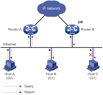
As shown in Figure 23, Host B and Host C are interested in the multicast data addressed to the multicast group G1. Host A is interested in the multicast data addressed to G2. The following process describes how the hosts join the multicast groups and how the IGMP querier (Router B in Figure 23) maintains the multicast group memberships:
1. The hosts send unsolicited IGMP reports to the multicast groups they want to join without having to wait for the IGMP queries.
2. The IGMP querier periodically multicasts IGMP queries (with the destination address of 224.0.0.1) to all hosts and routers on the local subnet.
3. After receiving a query message, the host whose report delay timer expires first sends an IGMP report to multicast group G1 to announce its membership for G1. In this example, Host B sends the report message. After receiving the report from Host B, Host C suppresses its own report for G1.
Because IGMP routers already know that G1 has a minimum of one member, other members do not need to report their memberships. This mechanism, known as the host IGMP report suppression, helps reduce traffic on the local subnet.
4. At the same time, Host A sends a report to the multicast group G2 after receiving a query.
5. Through the query and response process, the IGMP routers (Router A and Router B) determine that the local subnet has members of G1 and G2. The multicast routing protocol (PIM, for example) on the routers generates (*, G1) and (*, G2) multicast forwarding entries, where asterisk (*) represents any multicast source. These entries are the basis for subsequent multicast forwarding.
6. When the multicast data addressed to G1 or G2 reaches an IGMP router, the router looks up the multicast forwarding table. Based on the (*, G1) or (*, G2) entries, the router forwards the multicast data to the local subnet. Then, the receivers on the subnet can receive the data.
IGMPv1 does not define a leave group message (often called a leave message). When an IGMPv1 host is leaving a multicast group, it stops sending reports to that multicast group. If the subnet has no members for a multicast group, the IGMP routers will not receive any report addressed to that multicast group. In this case, the routers clear the information for that multicast group after a period of time.
IGMPv2 enhancements
Backwards-compatible with IGMPv1, IGMPv2 has introduced a querier election mechanism and a leave-group mechanism.
Querier election mechanism
In IGMPv1, the DR elected by the Layer 3 multicast routing protocol (such as PIM) acts as the querier.
IGMPv2 introduced an independent querier election mechanism. The querier election process is as follows:
1. Initially, every IGMPv2 router assumes itself to be the querier. Each router sends IGMP general query messages (called general queries) to all hosts and routers on the local subnet. The destination address is 224.0.0.1.
2. After receiving a general query, every IGMPv2 router compares the source IP address of the query with its own interface address. The router with the lowest IP address becomes the querier. All the other IGMPv2 routers become non-queriers.
3. All the non-queriers start the other querier present timer. If a router receives an IGMP query from the querier before the timer expires, it resets this timer. Otherwise, the router considers that the querier has timed out. In this case, the router initiates a new querier election process.
"Leave group" mechanism
In IGMPv1, when a host leaves a multicast group, it does not send any notification to the multicast routers. The multicast routers determine whether a group has members by using the maximum response time. This adds to the leave latency.
In IGMPv2, when a host is leaving a multicast group, the following process occurs:
1. The host sends a leave message to all routers on the local subnet. The destination address of leave messages is 224.0.0.2.
2. After receiving the leave message, the querier sends a configurable number of IGMP group-specific queries to the group that the host is leaving. Both the destination address field and the group address field of the message are the address of the multicast group that is being queried.
3. One of the remaining members (if any on the subnet) in the group should send a report within the maximum response time advertised in the group-specific queries.
4. If the querier receives a report for the group before the maximum response timer expires, it maintains the memberships for the group. Otherwise, the querier assumes that the local subnet has no member hosts for the group and stops maintaining the memberships for the group.
IGMPv3 enhancements
IGMPv3 is based on and is compatible with IGMPv1 and IGMPv2. It enhances the control capabilities of hosts and the query and report capabilities of IGMP routers.
Enhancements in control capability of hosts
IGMPv3 introduced two source filtering modes (Include and Exclude). These modes allow a host to receive or reject multicast data from the specified multicast sources. When a host joins a multicast group, one of the following occurs:
· If the host expects to receive multicast data from specific sources like S1, S2, …, it sends a report with the Filter-Mode denoted as "Include Sources (S1, S2, …)."
· If the host expects to reject multicast data from specific sources like S1, S2, …, it sends a report with the Filter-Mode denoted as "Exclude Sources (S1, S2, …)."
As shown in Figure 24, the network has two multicast sources: Source 1 (S1) and Source 2 (S2). Both of these sources can send multicast data to the multicast group G. Host B wants to receive the multicast data addressed to G from Source 1 but not from Source 2.
Figure 24 Flow paths of source-and-group-specific multicast traffic
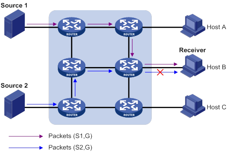
In IGMPv1 or IGMPv2, Host B cannot select multicast sources when it joins the multicast group G. The multicast streams from both Source 1 and Source 2 flow to Host B whether or not it needs them.
In IGMPv3, Host B can explicitly express that it needs to receive multicast data destined to the multicast group G from Source 1 but not from Source 2.
Enhancements in query and report capabilities
IGMPv3 introduces IGMP group-and-source queries and IGMP reports carrying group records.
· Query message carrying the source addresses
IGMPv3 is compatible with IGMPv1 and IGMPv2 and supports IGMP general queries and IGMP group-specific queries. It also introduces IGMP group-and-source-specific queries.
? A general query does not carry a group address or a source address.
? A group-specific query carries a group address, but no source address.
? A group-and-source-specific query carries a group address and one or more source addresses.
· Reports containing multiple group records
Unlike an IGMPv1 or IGMPv2 report, an IGMPv3 report is destined to 224.0.0.22 and contains one or more group records. Each group record contains a multicast group address and a multicast source address list.
Group records include the following categories:
? IS_IN—The current filtering mode is Include. The report sender requests the multicast data only from the sources specified in the Source Address field.
? IS_EX—The current filtering mode is Exclude. The report sender requests the multicast data from any sources except those specified in the Source Address field.
? TO_IN—The filtering mode has changed from Exclude to Include.
? TO_EX—The filtering mode has changed from Include to Exclude.
? ALLOW—The Source Address field contains a list of additional sources from which the receiver wants to obtain data. If the current filtering mode is Include, these sources are added to the multicast source list. If the current filtering mode is Exclude, these sources are deleted from the multicast source list.
? BLOCK—The Source Address field contains a list of the sources from which the receiver no longer wants to obtain data. If the current filtering mode is Include, these sources are deleted from the multicast source list. If the current filtering mode is Exclude, these sources are added to the multicast source list.
IGMP SSM mapping
An IGMPv3 host can explicitly specify multicast sources in its IGMPv3 reports. From the reports, the IGMP router can obtain the multicast source addresses and directly provide the SSM service. However, an IGMPv1 or IGMPv2 host cannot specify multicast sources in its IGMPv1 or IGMPv2 reports.
The IGMP SSM mapping feature enables the IGMP router to provide SSM support for IGMPv1 or IGMPv2 hosts. The router translates (*, G) in IGMPv1 or IGMPv2 reports into (G, INCLUDE, (S1, S2...)) based on the configured IGMP SSM mappings.
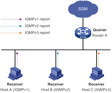
As shown in Figure 25, on an SSM network, Host A, Host B, and Host C run IGMPv1, IGMPv2, and IGMPv3, respectively. To provide the SSM service for Host A and Host B, you must configure the IGMP SSM mapping feature on Router A.
After IGMP SSM mappings are configured, Router A checks the multicast group address G in the received IGMPv1 or IGMPv2 report, and performs the following operations:
· If G is not in the SSM group range, Router A provides the ASM service.
· If G is in the SSM group range but does not match any IGMP SSM mapping, Router A drops the report.
· If G is in the SSM group range and matches IGMP SSM mappings, Router A translates (*, G) in the report into (G, INCLUDE, (S1, S2...)) to provide SSM services.
|
NOTE: The IGMP SSM mapping feature does not process IGMPv3 reports. |
For more information about SSM group ranges, see "Configuring PIM."
IGMP proxying
As shown in Figure 26, in a simple tree-shaped topology, it is not necessary to run multicast routing protocols, such as PIM, on edge devices. Instead, you can configure IGMP proxying on these devices. With IGMP proxying configured, the edge device acts as an IGMP proxy:
· For the upstream IGMP querier, the IGMP proxy device acts as a host.
· For the downstream receiver hosts, the IGMP proxy device acts as an IGMP querier.
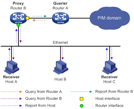
The following types of interfaces are defined in IGMP proxying:
· Host interface—An interface that is in the direction toward the root of the multicast forwarding tree. A host interface acts as a receiver host that is running IGMP. IGMP proxying must be enabled on this interface. This interface is also called the "proxy interface."
· Router interface—An interface that is in the direction toward the leaf of the multicast forwarding tree. A router interface acts as a router that is running IGMP. IGMP must be configured on this interface.
An IGMP proxy device maintains a group membership database, which stores the group memberships on all the router interfaces. The host interfaces and router interfaces perform actions based on this membership database.
· The host interfaces respond to queries according to the membership database or send join/leave messages when the database changes.
· The router interfaces participate in the querier election, send queries, and maintain memberships based on received IGMP reports.
IGMP support for VPNs
IGMP maintains group memberships on a per-interface basis. After receiving an IGMP message on an interface, IGMP processes the packet within the VPN to which the interface belongs. IGMP only communicates with other multicast protocols within the same VPN instance.
Protocols and standards
· RFC 1112, Host Extensions for IP Multicasting
· RFC 2236, Internet Group Management Protocol, Version 2
· RFC 3376, Internet Group Management Protocol, Version 3
Feature and hardware compatibility
The following matrix shows the feature and hardware compatibility:
|
Hardware |
IGMP compatibility |
|
MSR810/810-W/810-W-DB/810-LM/810-W-LM/810-10-PoE/810-LM-HK/810-W-LM-HK |
Yes |
|
MSR810-LMS/810-LUS |
No |
|
MSR2600-6-X1/2600-10-X1 |
Yes |
|
MSR 2630 |
Yes |
|
MSR3600-28/3600-51 |
Yes |
|
MSR3600-28-SI/3600-51-SI |
No |
|
MSR3610-X1/3610-X1-DP/3610-X1-DC/3610-X1-DP-DC |
Yes |
|
MSR 3610/3620/3620-DP/3640/3660 |
Yes |
|
MSR5620/5660/5680 |
Yes |
|
Hardware |
IGMP compatibility |
|
MSR810-LM-GL |
Yes |
|
MSR810-W-LM-GL |
Yes |
|
MSR830-6EI-GL |
Yes |
|
MSR830-10EI-GL |
Yes |
|
MSR830-6HI-GL |
Yes |
|
MSR830-10HI-GL |
Yes |
|
MSR2600-6-X1-GL |
Yes |
|
MSR3600-28-SI-GL |
No |
IGMP configuration task list
|
Tasks at a glance |
|
Configuring basic IGMP features: · (Required.) Enabling IGMP · (Optional.) Specifying an IGMP version · (Optional.) Configuring a static group member · (Optional.) Configuring a multicast group policy |
|
(Optional.) Configuring IGMP query and response parameters (Optional.) Enabling fast-leave processing |
|
(Optional.) Configuring IGMP SSM mappings |
|
· (Optional.) Enabling IGMP proxying · (Optional.) Enabling multicast forwarding on a non-querier interface · (Optional.) Configuring multicast load splitting on an IGMP proxy |
|
(Optional.) Enabling IGMP NSR |
Configuring basic IGMP features
Before you configure basic IGMP features, complete the following tasks:
· Configure any unicast routing protocol so that all devices can interoperate at the network layer.
· Configure PIM.
· Determine the IGMP version.
· Determine the multicast group and multicast source addresses for static group member configuration.
· Determine the ACL to be used in the multicast group policy.
Enabling IGMP
Enable IGMP on the interface where the multicast group memberships are established and maintained.
To enable IGMP:
|
Step |
Command |
Remarks |
|
1. Enter system view. |
system-view |
N/A |
|
2. Enable IP multicast routing and enter MRIB view. |
multicast routing [ vpn-instance vpn-instance-name ] |
By default, IP multicast routing is disabled. |
|
3. Return to system view. |
quit |
N/A |
|
4. Enter interface view. |
interface interface-type interface-number |
N/A |
|
5. Enable IGMP. |
igmp enable |
By default, IGMP is disabled. |
Specifying an IGMP version
For IGMP to operate correctly, specify the same IGMP version for all routers on the same subnet.
To specify an IGMP version:
|
Step |
Command |
Remarks |
|
1. Enter system view. |
system-view |
N/A |
|
2. Enter interface view. |
interface interface-type interface-number |
N/A |
|
3. Specify an IGMP version on the interface. |
igmp version version-number |
The default setting is 2. |
Configuring a static group member
You can configure an interface as a static group member of a multicast group. Then, the interface can always receive multicast data addressed to the specified multicast group.
A static group member does not respond to IGMP queries. When you complete or cancel this configuration on an interface, the interface does not send an unsolicited IGMP report or leave message.
Configuration restrictions and guidelines
The interface to be configured as a static group member has the following restrictions:
· If the interface is IGMP and PIM-SM enabled, it must be a PIM-SM DR.
· If the interface is IGMP enabled but not PIM-SM enabled, it must be an IGMP querier.
For more information about PIM-SM and DR, see "Configuring PIM."
Configuration procedure
To configure a static group member:
|
Step |
Command |
Remarks |
|
1. Enter system view. |
system-view |
N/A |
|
2. Enter interface view. |
interface interface-type interface-number |
N/A |
|
3. Configure the interface as a static group member. |
igmp static-group group-address [ source source-address ] |
By default, an interface is not a static group member of any multicast groups. |
Configuring a multicast group policy
This feature enables an interface to filter IGMP reports by using an ACL that specifies multicast groups and the optional sources. It is used to control the multicast groups that the hosts attached to an interface can join.
This configuration does not take effect on static group members.
To configure a multicast group policy:
|
Step |
Command |
Remarks |
|
1. Enter system view. |
system-view |
N/A |
|
2. Enter interface view. |
interface interface-type interface-number |
N/A |
|
3. Configure a multicast group policy. |
igmp group-policy ipv4-acl-number [ version-number ] |
By default, no IGMP multicast group policy exists on an interface. Hosts attached to the interface can join any multicast groups. |
Adjusting IGMP performance
Before adjusting IGMP performance, complete the following tasks:
· Configure any unicast routing protocol so that all devices can interoperate at the network layer.
· Configure basic IGMP features.
Configuring IGMP query and response parameters
The following are IGMP query and response parameters:
· IGMP querier's robustness variable—Number of times for retransmitting IGMP queries in case of packet loss. A higher robustness variable makes the IGMP querier more robust, but increases the timeout time for multicast groups.
· IGMP startup query interval—Interval at which an IGMP querier sends IGMP general queries at startup.
· IGMP startup query count—Number of IGMP general queries that an IGMP querier sends at startup.
· IGMP general query interval—Interval at which an IGMP querier sends IGMP general queries to check for multicast group members on the network.
· IGMP last member query interval—In IGMPv2, it sets the interval at which a querier sends group-specific queries after receiving a leave message. In IGMPv3, it sets the interval at which a querier sends group-and-source-specific queries after receiving a report that changes multicast source and group mappings.
· IGMP last member query count—In IGMPv2, it sets the number of group-specific queries that a querier sends after receiving a leave message. In IGMPv3, it sets the number of group-and-source-specific queries that a querier sends after receiving a report that changes multicast source and group mappings.
· IGMP maximum response time—Maximum time before a receiver responds with a report to an IGMP general query. This per-group timer is initialized to a random value in the range of 0 to the maximum response time specified in the IGMP query. When the timer value for a group decreases to 0, the receiver sends an IGMP report to the group.
· IGMP other querier present timer—Lifetime for an IGMP querier after a non-querier receives an IGMP general query. If the non-querier does not receive a new query when this timer expires, the non-querier considers that the querier has failed and starts a new querier election.
Configuration restrictions and guidelines
When you configure the IGMP query and response parameters, follow these restrictions and guidelines:
· You can configure the IGMP query and response parameters globally for all interfaces in IGMP view or for an interface in interface view. For an interface, the interface-specific configuration takes priority over the global configuration.
· To avoid frequent IGMP querier changes, set the IGMP other querier present timer greater than the IGMP general query interval. In addition, configure the same IGMP other querier present timer for all IGMP routers on the same subnet.
· To avoid mistakenly deleting multicast receivers, set the IGMP general query interval greater than the maximum response time for IGMP general queries.
· To speed up the response to IGMP queries and avoid simultaneous timer expirations that cause IGMP report traffic bursts, set an appropriate maximum response time.
? For IGMP general queries, the maximum response time is set by the max-response-time command.
? For IGMP group-specific queries and IGMP group-and-source-specific queries, the maximum response time equals the IGMP last member query interval.
· The following configurations take effect only on the devices that run IGMPv2 and IGMPv3:
? Maximum response time for IGMP general queries.
? IGMP last member query interval.
? IGMP last member query count.
? IGMP other querier present interval.
Configuring the IGMP query and response parameters globally
|
Step |
Command |
Remarks |
|
1. Enter system view. |
system-view |
N/A |
|
2. Enter IGMP view. |
N/A |
|
|
3. Set the IGMP querier's robustness variable. |
By default, the IGMP querier's robustness variable is 2. |
|
|
4. Set the IGMP startup query interval. |
By default, the IGMP startup query interval equals one quarter of the IGMP general query interval. |
|
|
5. Set the IGMP startup query count. |
By default, the IGMP startup query count equals the IGMP querier's robustness variable. |
|
|
6. Set the IGMP general query interval. |
By default, the IGMP general query interval is 125 seconds. |
|
|
7. Set the IGMP last member query interval. |
By default, the IGMP last member query interval is 1 second. |
|
|
8. Set the IGMP last member query count. |
By default, the IGMP last member query count equals the IGMP querier's robustness variable. |
|
|
9. Set the maximum response time for IGMP general queries. |
By default, the maximum response time for IGMP general queries is 10 seconds. |
|
|
10. Set the IGMP other querier present timer. |
By default, the IGMP other querier
present timer is calculated by using the following formula: |
Configuring the IGMP query and response parameters on an interface
|
Step |
Command |
Remarks |
|
1. Enter system view. |
N/A |
|
|
2. Enter interface view. |
N/A |
|
|
3. Set the IGMP querier's robustness variable. |
By default, the IGMP querier's robustness variable is 2. |
|
|
4. Set the IGMP startup query interval. |
By default, the IGMP startup query interval equals one quarter of the IGMP general query interval. |
|
|
5. Set the IGMP startup query count. |
By default, the IGMP startup query count equals the IGMP querier's robustness variable. |
|
|
6. Set the IGMP general query interval. |
igmp query-interval interval |
By default, the IGMP general query interval is 125 seconds. |
|
7. Set the IGMP last member query interval. |
By default, the IGMP last member query interval is 1 second. |
|
|
8. Set the IGMP last member query count. |
By default, the IGMP last member query count equals the IGMP querier's robustness variable. |
|
|
9. Set the maximum response time for IGMP general queries. |
By default, the maximum response time for IGMP general queries is 10 seconds. |
|
|
10. Set the IGMP other querier present timer. |
igmp other-querier-present-interval interval |
By default, the IGMP other querier
present timer is calculated by using the following formula: |
Enabling fast-leave processing
This feature enables an IGMP querier to send leave notifications to the upstream without sending group-specific or group-and-source-specific queries after receiving a leave message. Use this feature to reduce leave latency and to preserve the network bandwidth.
The fast-leave processing configuration takes effect only when the device runs IGMPv2 or IGMPv3.
To enable fast-leave processing:
|
Step |
Command |
Remarks |
|
1. Enter system view. |
system-view |
N/A |
|
2. Enter interface view. |
interface interface-type interface-number |
N/A |
|
3. Enable fast-leave processing. |
igmp fast-leave [ group-policy ipv4-acl-number ] |
By default, fast-leave processing is disabled. |
Configuring IGMP SSM mappings
This feature enables the device to provide SSM services for IGMPv1 or IGMPv2 hosts.
This feature does not process IGMPv3 messages. As a best practice, enable IGMPv3 on the receiver-side interface to avoid IGMPv3 hosts failing to join multicast groups.
Configuration prerequisites
Before you configure IGMP SSM mappings, complete the following tasks:
· Configure any unicast routing protocol so that all devices in the domain can interoperate at the network layer.
· Configure basic IGMP features.
Configuration procedure
To configure an IGMP SSM mapping:
|
Step |
Command |
Remarks |
|
1. Enter system view. |
system-view |
N/A |
|
2. Enter IGMP view. |
N/A |
|
|
3. Configure an IGMP SSM mapping. |
ssm-mapping source-address ipv4-acl-number |
By default, no IGMP SSM mappings exist. |
Configuring IGMP proxying
This section describes how to configure IGMP proxying.
Configuration prerequisites
Before you configure the IGMP proxying feature, complete the following tasks:
1. Configure a unicast routing protocol so that all devices in the domain can interoperate at the network layer.
2. Determine the router interfaces and host interfaces based on the network topology.
3. Enable IGMP on the router interfaces.
Enabling IGMP proxying
When you enable IGMP proxying, follow these restrictions and guidelines:
· You must enable IGMP proxying on the receiver-side interfaces.
· On an interface enabled with IGMP proxying, only the igmp version command takes effect and other IGMP commands do not take effect.
· If you enable both IGMP proxying and a multicast routing protocol (such as PIM or MSDP) on the same device, the multicast routing protocol does not take effect.
In IGMPv1, the DR is elected by PIM and acts as the IGMP querier. Because PIM does not take effect on a proxy device, a router interface running IGMPv1 cannot be elected as the DR. To ensure that the downstream receiver hosts on the router interface can receive multicast data, you must enable multicast forwarding on the interface. For more information, see "Enabling multicast forwarding on a non-querier interface."
To enable IGMP proxying:
|
Step |
Command |
Remarks |
|
1. Enter system view. |
system-view |
N/A |
|
2. Enable IP multicast routing and enter MRIB view. |
By default, IP multicast routing is disabled. |
|
|
3. Return to system view. |
N/A |
|
|
4. Enter interface view. |
interface interface-type interface-number |
N/A |
|
5. Enable IGMP proxying. |
igmp proxying enable |
By default, IGMP proxying is disabled. |
Enabling multicast forwarding on a non-querier interface
Typically, only IGMP queriers can forward multicast traffic and non-queriers cannot. This prevents multicast data from being repeatedly forwarded. If a router interface on an IGMP proxy device failed in the querier election, enable multicast forwarding on the interface to forward multicast data to attached receiver hosts.
Configuration restrictions and guidelines
A shared-media network might have multiple MLD proxies, including one proxy acting as a querier. To avoid duplicate multicast traffic, do not enable multicast forwarding on any of the non-querier MLD proxies for the network.
Configuration procedure
To enable multicast forwarding on a non-querier interface:
|
Step |
Command |
Remarks |
|
1. Enter system view. |
system-view |
N/A |
|
2. Enter interface view. |
interface interface-type interface-number |
N/A |
|
3. Enable multicast forwarding on the interface. |
igmp proxy forwarding |
By default, multicast forwarding is disabled on a non-querier interface. |
Configuring multicast load splitting on an IGMP proxy
This feature enables all proxy interfaces on an IGMP proxy device to share multicast traffic on a per-group basis.
To enable multicast load splitting on an IGMP proxy device:
|
Step |
Command |
Remarks |
|
1. Enter system view. |
system-view |
N/A |
|
2. Enter IGMP view. |
N/A |
|
|
3. Enable multicast load splitting. |
By default, multicast load splitting is disabled, and only the proxy interface with the highest IP address on the IGMP proxy device forwards multicast data. |
Enabling IGMP NSR
The following matrix shows the feature and hardware compatibility:
|
Hardware |
IGMP NSR compatibility |
|
MSR810/810-W/810-W-DB/810-LM/810-W-LM/810-10-PoE/810-LM-HK/810-W-LM-HK/810-LMS/810-LUS |
No |
|
MSR2600-6-X1/2600-10-X1 |
No |
|
MSR 2630 |
Yes |
|
MSR3600-28/3600-51 |
Yes |
|
MSR3600-28-SI/3600-51-SI |
No |
|
MSR3610-X1/3610-X1-DP/3610-X1-DC/3610-X1-DP-DC |
Yes |
|
MSR 3610/3620/3620-DP/3640/3660 |
Yes |
|
MSR5620/5660/5680 |
Yes |
|
Hardware |
IGMP NSR compatibility |
|
MSR810-LM-GL |
No |
|
MSR810-W-LM-GL |
No |
|
MSR830-6EI-GL |
No |
|
MSR830-10EI-GL |
No |
|
MSR830-6HI-GL |
No |
|
MSR830-10HI-GL |
No |
|
MSR2600-6-X1-GL |
No |
|
MSR3600-28-SI-GL |
No |
This feature backs up information about IGMP interfaces and IGMP multicast groups to the standby process. The device recovers the information without cooperation of other devices when an active/standby switchover occurs. Use this feature to prevent an active/standby switchover from affecting the multicast service.
To enable IGMP NSR:
|
Step |
Command |
Remarks |
|
1. Enter system view. |
system-view |
N/A |
|
2. Enable IGMP NSR. |
igmp non-stop-routing |
By default, IGMP NSR is disabled. |
Displaying and maintaining IGMP
|
|
CAUTION: The reset igmp group command might cause multicast data transmission failures. |
Execute display commands in any view and reset commands in user view.
|
Task |
Command |
|
Display information about IGMP multicast groups. |
display igmp [ vpn-instance vpn-instance-name ] group [ group-address | interface interface-type interface-number ] [ static | verbose ] |
|
Display IGMP information for interfaces. |
display igmp [ vpn-instance vpn-instance-name ] interface [ interface-type interface-number ] [ proxy ] [ verbose ] |
|
Display multicast group membership information maintained by the IGMP proxy. |
|
|
Display multicast routing entries maintained by the IGMP proxy. |
|
|
Display IGMP SSM mappings. |
display igmp [ vpn-instance vpn-instance-name ] ssm-mapping group-address |
|
Clear dynamic IGMP multicast group entries. |
reset igmp [ vpn-instance vpn-instance-name ] group { all | interface interface-type interface-number { all | group-address [ mask { mask | mask-length } ] [ source-address [ mask { mask | mask-length } ] ] } } |
IGMP configuration examples
Basic IGMP features configuration examples
Network requirements
As shown in Figure 27:
· OSPF and PIM-DM run on the network.
· VOD streams are sent to receiver hosts in multicast. Receiver hosts of different organizations form stub networks N1 and N2. Host A and Host C are receiver hosts in N1 and N2, respectively.
· IGMPv2 runs between Router A and N1, and between the other two routers and N2. Router A acts as the IGMP querier in N1. Router B acts as the IGMP querier in N2 because it has a lower IP address.
Configure the routers to meet the following requirements:
· The hosts in N1 can join only multicast group 224.1.1.1.
· The hosts in N2 can join any multicast groups.
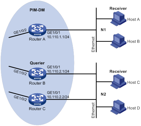
Configuration procedure
1. Assign an IP address and subnet mask to each interface, as shown in Figure 27. (Details not shown.)
2. Configure OSPF on the routers in the PIM-DM domain. (Details not shown.)
3. Enable IP multicast routing, and enable IGMP and PIM-DM:
# On Router A, enable IP multicast routing.
<RouterA> system-view
[RouterA] multicast routing
[RouterA-mrib] quit
# Enable IGMP on GigabitEthernet 1/0/1.
[RouterA] interface gigabitethernet 1/0/1
[RouterA-GigabitEthernet1/0/1] igmp enable
[RouterA-GigabitEthernet1/0/1] quit
# Enable PIM-DM on GigabitEthernet 1/0/2.
[RouterA] interface gigabitethernet 1/0/2
[RouterA-GigabitEthernet1/0/2] pim dm
[RouterA-GigabitEthernet1/0/2] quit
# On Router B, enable IP multicast routing.
<RouterB> system-view
[RouterB] multicast routing
[RouterB-mrib] quit
# Enable IGMP on GigabitEthernet 1/0/1.
[RouterB] interface gigabitethernet 1/0/1
[RouterB-GigabitEthernet1/0/1] igmp enable
[RouterB-GigabitEthernet1/0/1] quit
# Enable PIM-DM on GigabitEthernet 1/0/2.
[RouterB] interface gigabitethernet 1/0/2
[RouterB-GigabitEthernet1/0/2] pim dm
[RouterB-GigabitEthernet1/0/2] quit
# On Router C, enable IP multicast routing.
<RouterC> system-view
[RouterC] multicast routing
[RouterC-mrib] quit
# Enable IGMP on GigabitEthernet 1/0/1.
[RouterC] interface gigabitethernet 1/0/1
[RouterC-GigabitEthernet1/0/1] igmp enable
[RouterC-GigabitEthernet1/0/1] quit
# Enable PIM-DM on GigabitEthernet 1/0/2.
[RouterC] interface gigabitethernet 1/0/2
[RouterC-GigabitEthernet1/0/2] pim dm
[RouterC-GigabitEthernet1/0/2] quit
4. Configure a multicast group policy on Router A so that the hosts connected to GigabitEthernet 1/0/1 can join only multicast group 224.1.1.1.
[RouterA] acl basic 2001
[RouterA-acl-ipv4-basic-2001] rule permit source 224.1.1.1 0
[RouterA-acl-ipv4-basic-2001] quit
[RouterA] interface gigabitethernet 1/0/1
[RouterA-GigabitEthernet1/0/1] igmp group-policy 2001
[RouterA-GigabitEthernet1/0/1] quit
Verifying the configuration
# Display IGMP information for GigabitEthernet 1/0/1 on Router B.
[RouterB] display igmp interface gigabitethernet 1/0/1
GigabitEthernet1/0/1(10.110.2.1):
IGMP is enabled.
IGMP version: 2
Query interval for IGMP: 125s
Other querier present time for IGMP: 255s
Maximum query response time for IGMP: 10s
Querier for IGMP: 10.110.2.1 (This router)
IGMP groups reported in total: 1
IGMP SSM mapping configuration example
Network requirements
As shown in Figure 28:
· OSPF runs on the network.
· The PIM-SM domain uses the SSM model for multicast delivery. The SSM group range is 232.1.1.0/24.
· IGMPv3 runs on GigabitEthernet 1/0/1 on Router D. The receiver host runs IGMPv2, and does not support IGMPv3. The receiver host cannot specify multicast sources in its membership reports.
· Source 1, Source 2, and Source 3 send multicast packets to multicast groups in the SSM group range 232.1.1.0/24.
Configure the IGMP SSM mapping feature on Router D so that the receiver host can receive multicast data only from Source 1 and Source 3.
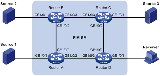
Table 7 Interface and IP address assignment
|
Device |
Interface |
IP address |
Device |
Interface |
IP address |
|
Source 1 |
— |
133.133.1.1/24 |
Source 3 |
— |
133.133.3.1/24 |
|
Source 2 |
— |
133.133.2.1/24 |
Receiver |
— |
133.133.4.1/24 |
|
Router A |
133.133.1.2/24 |
Router C |
133.133.3.2/24 |
||
|
Router A |
192.168.1.1/24 |
Router C |
192.168.3.1/24 |
||
|
Router A |
192.168.4.2/24 |
Router C |
192.168.2.2/24 |
||
|
Router B |
133.133.2.2/24 |
Router D |
133.133.4.2/24 |
||
|
Router B |
192.168.1.2/24 |
Router D |
192.168.3.2/24 |
||
|
Router B |
192.168.2.1/24 |
Router D |
192.168.4.1/24 |
Configuration procedure
1. Assign an IP address and subnet mask to each interface, as shown in Figure 28. (Details not shown.)
2. Configure OSPF on the routers in the PIM-SM domain. (Details not shown.)
3. Enable IP multicast routing, PIM-SM, and IGMP:
# On Router D, enable IP multicast routing.
<RouterD> system-view
[RouterD] multicast routing
[RouterD-mrib] quit
# Enable IGMPv3 on the receiver-side interface (GigabitEthernet 1/0/1).
[RouterD] interface gigabitethernet 1/0/1
[RouterD-GigabitEthernet1/0/1] igmp enable
[RouterD-GigabitEthernet1/0/1] igmp version 3
[RouterD-GigabitEthernet1/0/1] quit
# Enable PIM-SM on the other interfaces.
[RouterD] interface gigabitethernet 1/0/2
[RouterD-GigabitEthernet1/0/2] pim sm
[RouterD-GigabitEthernet1/0/2] quit
[RouterD] interface gigabitethernet 1/0/3
[RouterD-GigabitEthernet1/0/3] pim sm
[RouterD-GigabitEthernet1/0/3] quit
# On Router A, enable IP multicast routing.
<RouterA> system-view
[RouterA] multicast routing
[RouterA-mrib] quit
# Enable PIM-SM on each interface.
[RouterA] interface gigabitethernet 1/0/1
[RouterA-GigabitEthernet1/0/1] pim sm
[RouterA-GigabitEthernet1/0/1] quit
[RouterA] interface gigabitethernet 1/0/2
[RouterA-GigabitEthernet1/0/2] pim sm
[RouterA-GigabitEthernet1/0/2] quit
[RouterA] interface gigabitethernet 1/0/3
[RouterA-GigabitEthernet1/0/3] pim sm
[RouterA-GigabitEthernet1/0/3] quit
# Configure Router B and Router C in the same way Router A is configured. (Details not shown.)
4. Configure the SSM group range:
# On Router D, specify 232.1.1.0/24 as the SSM group range.
[RouterD] acl basic 2000
[RouterD-acl-ipv4-basic-2000] rule permit source 232.1.1.0 0.0.0.255
[RouterD-acl-ipv4-basic-2000] quit
[RouterD] pim
[RouterD-pim] ssm-policy 2000
[RouterD-pim] quit
# Configure the SSM group range on Router A, Router B, and Router C in the same way Router D is configured. (Details not shown.)
5. Configure IGMP SSM mappings on Router D.
[RouterD] igmp
[RouterD-igmp] ssm-mapping 133.133.1.1 2000
[RouterD-igmp] ssm-mapping 133.133.3.1 2000
[RouterD-igmp] quit
Verifying the configuration
# On Router D, display IGMP SSM mappings for multicast group 232.1.1.1 on the public network.
[RouterD] display igmp ssm-mapping 232.1.1.1
Group: 232.1.1.1
Source list:
133.133.1.1
133.133.3.1
# Display information about IGMP multicast groups that hosts have dynamically joined on the public network.
<RouterD> display igmp group 232.1.1.1 verbose
GigabitEthernet1/0/1((133.133.4.2):
IGMP groups reported in total: 1
Group: 232.1.1.1
Uptime: 00:00:34
Exclude expires: 00:04:16
Mapping expires: 00:02:16
Last reporter: 133.133.4.1
Last-member-query-counter: 0
Last-member-query-timer-expiry: Off
Mapping last-member-query-counter: 0
Mapping last-member-query-timer-expiry: Off
Group mode: Exclude
Version1-host-present-timer-expiry: Off
Version2-host-present-timer-expiry: 00:02:11
Mapping version1-host-present-timer-expiry: Off
Source list (sources in total: 2):
Source: 133.133.1.1
Uptime: 00:00:03
V3 expires: 00:04:16
Mapping expires: 00:02:16
Last-member-query-counter: 0
Last-member-query-timer-expiry: Off
Source: 133.133.3.1
Uptime: 00:00:03
V3 expires: 00:04:16
Mapping expires: 00:02:16
Last-member-query-counter: 0
Last-member-query-timer-expiry: Off
# Display PIM routing entries on the public network.
[RouterD] display pim routing-table
Total 0 (*, G) entry; 2 (S, G) entry
(133.133.1.1, 232.1.1.1)
Protocol: pim-ssm, Flag:
UpTime: 00:13:25
Upstream interface: GigabitEthernet1/0/3
Upstream neighbor: 192.168.4.2
RPF prime neighbor: 192.168.4.2
Downstream interface(s) information:
Total number of downstreams: 1
1: GigabitEthernet1/0/1
Protocol: igmp, UpTime: 00:13:25, Expires: -
(133.133.3.1, 232.1.1.1)
Protocol: pim-ssm, Flag:
UpTime: 00:13:25
Upstream interface: GigabitEthernet1/0/2
Upstream neighbor: 192.168.3.1
RPF prime neighbor: 192.168.3.1
Downstream interface(s) information:
Total number of downstreams: 1
1: GigabitEthernet1/0/1
Protocol: igmp, UpTime: 00:13:25, Expires: -
IGMP proxying configuration example
Network requirements
As shown in Figure 29:
· PIM-DM runs on the core network.
· Host A and Host C on the stub network receive VOD information sent to multicast group 224.1.1.1.
Configure the IGMP proxying feature on Router B so that Router B can maintain group memberships and forward multicast traffic without running PIM-DM.
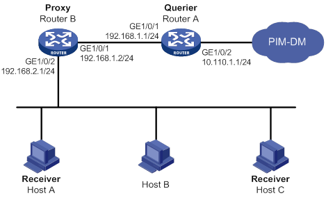
Configuration procedure
1. Assign an IP address and subnet mask to each interface, as shown in Figure 29. (Details not shown.)
2. Configure unicast routes to make sure devices can reach other. (Details not shown.)
3. Enable IP multicast routing, PIM-DM, IGMP, and IGMP proxying:
# On Router A, enable IP multicast routing.
[RouterA] multicast routing
[RouterA-mrib] quit
# Enable PIM-DM on GigabitEthernet 1/0/2.
[RouterA] interface gigabitethernet 1/0/2
[RouterA-GigabitEthernet1/0/2] pim dm
[RouterA-GigabitEthernet1/0/2] quit
# Enable IGMP on GigabitEthernet 1/0/1.
[RouterA] interface gigabitethernet 1/0/1
[RouterA-GigabitEthernet1/0/1] igmp enable
[RouterA-GigabitEthernet1/0/1] quit
# On Router B, enable IP multicast routing.
[RouterB] multicast routing
[RouterB-mrib] quit
# Enable IGMP proxying on GigabitEthernet 1/0/1.
[RouterB] interface gigabitethernet 1/0/1
[RouterB-GigabitEthernet1/0/1] igmp proxy enable
[RouterB-GigabitEthernet1/0/1] quit
# Enable IGMP on GigabitEthernet 1/0/2.
[RouterB] interface gigabitethernet 1/0/2
[RouterB-GigabitEthernet1/0/2] igmp enable
[RouterB-GigabitEthernet1/0/2] quit
Verifying the configuration
# Display multicast group membership information maintained by the IGMP proxy on Router B.
[RouterB] display igmp proxy group
IGMP proxy group records in total: 1
GigabitEthernet1/0/1(192.168.1.2):
IGMP proxy group records in total: 1
Group address Member state Expires
224.1.1.1 Delay 00:00:02
Troubleshooting IGMP
No membership information on the receiver-side router
Symptom
When a host sends a report for joining multicast group G, no membership information of multicast group G exists on the router closest to that host.
Solution
To resolve the problem:
1. Use the display igmp interface command to verify that the networking, interface connection, and IP address configuration are correct.
2. Use the display current-configuration command to verify that multicast routing is enabled. If it is not enabled, use the multicast routing command in system view to enable IP multicast routing. In addition, verify that IGMP is enabled on the associated interfaces.
3. Use the display igmp interface command to verify that the IGMP version on the interface is lower than that on the host.
4. Use the display current-configuration interface command to verify that no multicast group policies have been configured to filter IGMP reports for multicast group G.
5. If the problem persists, contact H3C Support.
Inconsistent membership information on the routers on the same subnet
Symptom
Different memberships are maintained on different IGMP routers on the same subnet.
Solution
To resolve the problem:
1. Use the display current-configuration command to verify the IGMP information on the interfaces. Make sure the routers on the subnet have the same IGMP settings on their interfaces.
2. Use the display igmp interface command on all routers on the same subnet to verify the IGMP-related timer settings. Make sure the settings are consistent on all the routers.
3. Use the display igmp interface command to verify that all routers on the same subnet are running the same IGMP version.
4. If the problem persists, contact H3C Support.
Configuring PIM
Overview
Protocol Independent Multicast (PIM) provides IP multicast forwarding by leveraging unicast static routes or unicast routing tables generated by any unicast routing protocol, such as RIP, OSPF, IS-IS, or BGP. PIM uses the underlying unicast routing to generate a multicast routing table without relying on any particular unicast routing protocol.
PIM uses the RPF mechanism to implement multicast forwarding. When a multicast packet arrives on an interface of the device, it undergoes an RPF check. If the RPF check succeeds, the device creates a multicast routing entry and forwards the packet. If the RPF check fails, the device discards the packet. For more information about RPF, see "Configuring multicast routing and forwarding."
Based on the implementation mechanism, PIM includes the following categories:
· Protocol Independent Multicast–Dense Mode (PIM-DM)
· Protocol Independent Multicast–Sparse Mode (PIM-SM)
· Bidirectional Protocol Independent Multicast (BIDIR-PIM)
· Protocol Independent Multicast Source-Specific Multicast (PIM-SSM)
In this document, a PIM domain refers to a network that contains PIM routers.
PIM-DM overview
PIM-DM uses the push mode for multicast forwarding, and is suitable for small-sized networks with densely distributed multicast members.
PIM-DM assumes that all downstream nodes want to receive multicast data from a source, so multicast data is flooded to all downstream nodes on the network. Branches without downstream receivers are pruned from the forwarding trees. When a pruned branch has new receivers, the graft mechanism turns the pruned branch into a forwarding branch.
In PIM-DM, the multicast forwarding paths for a multicast group constitutes a forwarding tree. The forwarding tree is rooted at the multicast source and has multicast group members as its "leaves." Because the forwarding tree consists of the shortest paths from the multicast source to the receivers, it is also called a "shortest path tree (SPT)."
Neighbor discovery
In a PIM domain, each PIM interface on a router periodically multicasts PIM hello messages to all other PIM routers (identified by the address 224.0.0.13) on the local subnet. Through the exchanging of hello messages, all PIM routers on the subnet determine their PIM neighbors, maintain PIM neighboring relationship with other routers, and build and maintain SPTs.
SPT building
The process of building an SPT is the flood-and-prune process:
1. In a PIM-DM domain, the multicast data from the multicast source S to the multicast group G is flooded throughout the domain. A router performs an RPF check on the multicast data. If the RPF check succeeds, the router creates an (S, G) entry and forwards the data to all downstream nodes on the network. In the flooding process, all the routers in the PIM-DM domain create the (S, G) entry.
2. The nodes without downstream receivers are pruned. A router that has no downstream receivers multicasts a prune message to all PIM routers on the subnet. When an upstream node receives the prune message, it removes the receiving interface from the (S, G) entry. In this way, the upstream stream node stops forwarding subsequent packets addressed to that multicast group down to this node.
|
|
NOTE: An (S, G) entry contains a multicast source address S, a multicast group address G, an outgoing interface list, and an incoming interface. |
A prune process is initiated by a leaf router. As shown in Figure 30, the router interface that does not have any downstream receivers initiates a prune process by sending a prune message toward the multicast source. This prune process goes on until only necessary branches are left in the PIM-DM domain, and these necessary branches constitute an SPT.
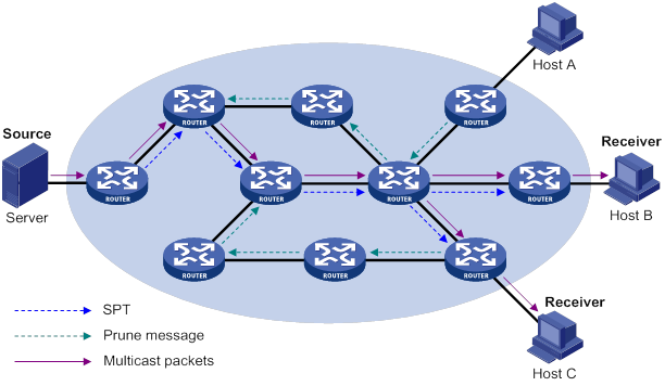
The pruned state of a branch has a finite holdtime timer. When the timer expires, multicast data is again forwarded to the pruned branch. The flood-and-prune cycle takes place periodically to maintain the forwarding branches.
Graft
A previously pruned branch might have new downstream receivers. To reduce the latency for resuming the forwarding capability of this branch, a graft mechanism is used as follows:
1. The node that needs to receive the multicast data sends a graft message to its upstream node, telling it to rejoin the SPT.
2. After receiving this graft message on an interface, the upstream node adds the receiving interface to the outgoing interface list of the (S, G) entry. It also sends a graft-ack message to the graft sender.
3. If the graft sender receives a graft-ack message, the graft process finishes. Otherwise, the graft sender continues to send graft messages at a graft retry interval until it receives an acknowledgment from its upstream node.
Assert
On a subnet with more than one multicast router, the assert mechanism shuts off duplicate multicast flows to the network. It does this by electing a unique multicast forwarder for the subnet.
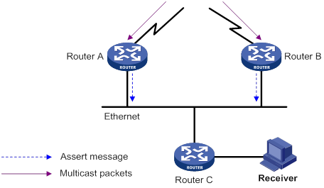
As shown in Figure 31, after Router A and Router B receive an (S, G) packet from the upstream node, they both forward the packet to the local subnet. As a result, the downstream node Router C receives two identical multicast packets. In addition, both Router A and Router B, on their downstream interfaces, receive a duplicate packet forwarded by the other. After detecting this condition, both routers send an assert message to all PIM routers (224.0.0.13) on the local subnet through the interface that received the packet. The assert message contains the multicast source address (S), the multicast group address (G), and the metric preference and metric of the unicast route/MBGP route/static multicast route to the multicast source. By comparing these parameters, either Router A or Router B becomes the unique forwarder of the subsequent (S, G) packets on the shared-media LAN. The comparison process is as follows:
1. The router with a higher metric preference to the multicast source wins.
2. If both routers have the same metric preference, the router with a smaller metric wins.
3. If both routers have the same metric, the router with a higher IP address on the downstream interface wins.
PIM-SM overview
PIM-DM uses the flood-and-prune cycles to build SPTs for multicast data forwarding. Although an SPT has the shortest paths from the multicast source to the receivers, it is built with a low efficiency. Therefore, PIM-DM is not suitable for large and medium-sized networks.
PIM-SM uses the pull mode for multicast forwarding, and it is suitable for large- and medium-sized networks with sparsely and widely distributed multicast group members.
PIM-SM assumes that no hosts need multicast data. A multicast receiver must express its interest in the multicast data for a multicast group before the data is forwarded to it. A rendezvous point (RP) is the core of a PIM-SM domain. Relying on the RP, SPTs and rendezvous point trees (RPTs) are established and maintained to implement multicast data forwarding. An SPT is rooted at the multicast source and has the RPs as its leaves. An RPT is rooted at the RP and has the receiver hosts as its leaves.
Neighbor discovery
PIM-SM uses the same neighbor discovery mechanism as PIM-DM does. For more information, see "Neighbor discovery."
DR election
A designated router (DR) is required on both the source-side network and receiver-side network. A source-side DR acts on behalf of the multicast source to send register messages to the RP. The receiver-side DR acts on behalf of the multicast receivers to send join messages to the RP.
PIM-DM does not require a DR. However, if IGMPv1 runs on any shared-media LAN in a PIM-DM domain, a DR must be elected to act as the IGMPv1 querier for the LAN. For more information about IGMP, see "Configuring IGMP."
|
|
IMPORTANT: IGMP must be enabled on the device that acts as the receiver-side DR. Otherwise, the receiver hosts attached to the DR cannot join any multicast groups. |
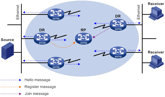
As shown in Figure 32, the DR election process is as follows:
1. The routers on the shared-media LAN send hello messages to one another. The hello messages contain the DR priority for DR election. The router with the highest DR priority is elected as the DR.
2. The router with the highest IP address wins the DR election under one of following conditions:
? All the routers have the same DR election priority.
? A router does not support carrying the DR priority in hello messages.
If the DR fails, its PIM neighbor lifetime expires and the other routers will initiate to elect a new DR.
RP discovery
An RP is the core of a PIM-SM domain. For a small-sized, simple network, one RP is enough for multicast forwarding throughout the network. In this case, you can specify a static RP on each router in the PIM-SM domain. However, in a PIM-SM network that covers a wide area, a huge amount of multicast data is forwarded by the RP. To lessen the RP burden and optimize the topological structure of the RPT, you can configure multiple candidate-RPs (C-RPs) in a PIM-SM domain. An RP is dynamically elected from the multiple C-RPs through the bootstrap mechanism. An elected RP provides services for a different multicast group. For this purpose, you must configure a bootstrap router (BSR). A BSR acts as the administrative core of a PIM-SM domain. A PIM-SM domain has only one BSR, but can have multiple candidate-BSRs (C-BSRs). If the BSR fails, a new BSR can be automatically elected from the C-BSRs and avoid service interruption.
|
|
NOTE: · An RP can provide services for multiple multicast groups, but a multicast group only uses one RP. · A device can act as a C-RP and a C-BSR at the same time. |
As shown in Figure 33, each C-RP periodically unicasts its advertisement messages (C-RP-Adv messages) to the BSR. An advertisement message contains the address of the advertising C-RP and the multicast group range to which it is designated. The BSR collects these advertisement messages and organizes the C-RP information into an RP-set, which is a database of mappings between multicast groups and RPs. The BSR encapsulates the RP-set information in the bootstrap messages (BSMs) and floods the BSMs to the entire PIM-SM domain.
Figure 33 Information exchange between C-RPs and BSR
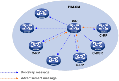
Based on the information in the RP-set, all routers on the network can select an RP for a specific multicast group based on the following rules:
1. The C-RP that is designated to the smallest group range wins.
2. If the C-RPs are designated to the same group ranges, the C-RP with the highest priority wins.
3. If the C-RPs have the same priority, the C-RP with the largest hash value wins. The hash value is calculated through the hash algorithm.
4. If the C-RPs have the same hash value, the C-RP with the highest IP address wins.
Anycast RP
PIM-SM requires only one active RP to serve each multicast group. If the active RP fails, the multicast traffic might be interrupted. The Anycast RP mechanism enables redundancy backup among RPs by configuring multiple RPs with the same IP address. A multicast source registers with the closest RP or a receiver joins the closest RP to implement source information synchronization.
Anycast RP has the following benefits:
· Optimal RP path—A multicast source registers with the closest RP to build an optimal SPT. A receiver joins the closest RP to build an optimal RPT.
· Redundancy backup among RPs—When an RP fails, the RP-related sources will register with the closest available RPs and the receiver-side DRs will join the closest available RPs. This provides redundancy backup among RPs.
Anycast RP is implemented in either of the following methods:
· Anycast RP through MSDP—In this method, you can configure multiple RPs with the same IP address for one multicast group and configure MSDP peering relationships between them. For more information about Anycast RP through MSDP, see "Configuring MSDP."
· Anycast RP through PIM-SM—In this method, you can configure multiple RPs for one multicast group and add them to an Anycast RP set. This method introduces the following concepts:
? Anycast RP set—A set of RPs that are designated to the same multicast group.
? Anycast RP member—Each RP in the Anycast RP set.
? Anycast RP member address—IP address of each Anycast RP member for communication among the RP members.
? Anycast RP address—IP address of the Anycast RP set for communication within the PIM-SM domain. It is also known as RPA.
As shown in Figure 34, RP 1, RP 2, and RP 3 are members of an Anycast RP set.
Figure 34 Anycast RP through PIM-SM
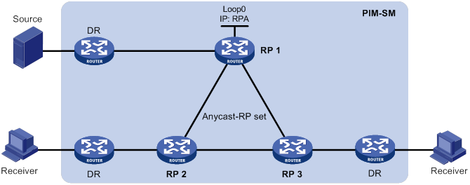
The following describes how Anycast RP through PIM-SM is implemented:
a. RP 1 receives a register message destined to RPA. Because the message is not from other Anycast RP members (RP 2 or RP 3), RP 1 considers that the register message is from the DR. RP 1 changes the source IP address of the register message to its own address and sends the message to the other members (RP 2 and RP 3).
If a router acts as both a DR and an RP, it creates a register message, and then forwards the message to the other RP members.
b. After receiving the register message, RP 2 and RP 3 find out that the source address of the register message is an Anycast RP member address. They stop forwarding the message to other routers.
In Anycast RP implementation, an RP must forward the register message from the DR to other Anycast RP members to synchronize multicast source information.
RPT building
Figure 35 RPT building in a PIM-SM domain

As shown in Figure 35, the process of building an RPT is as follows:
1. When a receiver wants to join the multicast group G, it uses an IGMP message to inform the receiver-side DR.
2. After getting the receiver information, the DR sends a join message, which travels hop by hop to the RP for the multicast group.
3. The routers along the path from the DR to the RP form an RPT branch. Each router on this branch adds to its forwarding table a (*, G) entry, where the asterisk (*) represents any multicast source. The RP is the root of the RPT, and the DR is a leaf of the RPT.
When the multicast data addressed to the multicast group G reaches the RP, the RP forwards the data to the DR along the established RPT, and finally to the receiver.
When a receiver is no longer interested in the multicast data addressed to the multicast group G, the receiver-side DR sends a prune message. The prune message goes hop by hop along the RPT to the RP. After receiving the prune message, the upstream node deletes the interface that connects to this downstream node from the outgoing interface list. At the same time, the upstream router checks for the existence of receivers for that multicast group. If no receivers for the multicast group exist, the router continues to forward the prune message to its upstream router.
Multicast source registration
The multicast source uses the registration process to inform an RP of its presence.
Figure 36 Multicast source registration
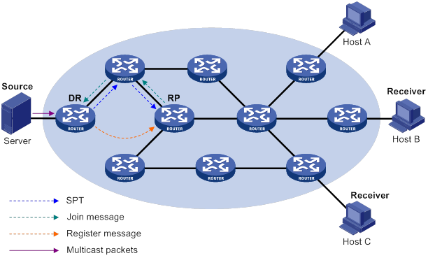
As shown in Figure 36, the multicast source registers with the RP as follows:
1. The multicast source S sends the first multicast packet to the multicast group G. When receiving the multicast packet, the source-side DR encapsulates the packet into a PIM register message and unicasts the message to the RP.
2. After the RP receives the register message, it decapsulates the register message and forwards the register message down to the RPT. Meanwhile, it sends an (S, G) source-specific join message toward the multicast source. The routers along the path from the RP to the multicast source constitute an SPT branch. Each router on this branch creates an (S, G) entry in its forwarding table.
3. The subsequent multicast data from the multicast source are forwarded to the RP along the established SPT. When the multicast data reaches the RP along the SPT, the RP forwards the data to the receivers along the RPT. Meanwhile, it unicasts a register-stop message to the source-side DR to prevent the DR from unnecessarily encapsulating the data.
Switchover to SPT
|
|
CAUTION: If the switch is an RP, disabling switchover to SPT might cause multicast traffic forwarding failures on the source-side DR. When disabling switchover to SPT, be sure you fully understand its impact on your network. |
In a PIM-SM domain, only one RP and one RPT provide services for a specific multicast group. Before the switchover to SPT occurs, the source-side DR encapsulates all multicast data in register messages and sends them to the RP. After receiving these register messages, the RP decapsulates them and forwards them to the receiver-side DR along the RPT.
Multicast forwarding along the RPT has the following weaknesses:
· Encapsulation and decapsulation are complex on the source-side DR and the RP.
· The path for a multicast packet might not be the shortest one.
· The RP might be overloaded by multicast traffic bursts.
To eliminate these weaknesses, PIM-SM allows an RP or the receiver-side DR to initiate the switchover to SPT when the traffic rate exceeds a specific threshold.
· The RP initiates the switchover to SPT:
The RP periodically checks the multicast packet forwarding rate. If the RP finds that the traffic rate exceeds the specified threshold, it sends an (S, G) source-specific join message toward the multicast source. The routers along the path from the RP to the multicast source constitute an SPT. The subsequent multicast data is forwarded to the RP along the SPT without being encapsulated into register messages.
For more information about the switchover to SPT initiated by the RP, see "Multicast source registration."
· The receiver-side DR initiates the switchover to SPT:
The receiver-side DR periodically checks the forwarding rate of the multicast packets that the multicast source S sends to the multicast group G. If the forwarding rate exceeds the specified threshold, the DR initiates the switchover to SPT as follows:
a. The receiver-side DR sends an (S, G) source-specific join message toward the multicast source. The routers along the path create an (S, G) entry in their forwarding table to constitute an SPT branch.
b. When the multicast packets reach the router where the RPT and the SPT branches, the router drops the multicast packets that travel along the RPT. It then sends a prune message with the RP bit toward the RP.
c. After receiving the prune message, the RP forwards it toward the multicast source (supposed only one receiver exists). Thus, the switchover to SPT is completed. The subsequent multicast packets travel along the SPT from the multicast source to the receiver hosts.
With the switchover to SPT, PIM-SM builds SPTs more economically than PIM-DM does.
Assert
PIM-SM uses a similar assert mechanism as PIM-DM does. For more information, see "Assert."
BIDIR-PIM overview
In some many-to-many applications, such as a multi-side video conference, multiple receivers of a multicast group might be interested in the multicast data from multiple multicast sources. With PIM-DM or PIM-SM, each router along the SPT must create an (S, G) entry for each multicast source, consuming a lot of system resources.
BIDIR-PIM addresses the problem. Derived from PIM-SM, BIDIR-PIM builds and maintains a bidirectional RPT, which is rooted at the RP and connects the multicast sources and the receivers. Along the bidirectional RPT, the multicast sources send multicast data to the RP, and the RP forwards the data to the receivers. Each router along the bidirectional RPT needs to maintain only one (*, G) entry, saving system resources.
BIDIR-PIM is suitable for a network with dense multicast sources and receivers.
Neighbor discovery
BIDIR-PIM uses the same neighbor discovery mechanism as PIM-SM does. For more information, see "Neighbor discovery."
RP discovery
BIDIR-PIM uses the same RP discovery mechanism as PIM-SM does. For more information, see "RP discovery." In BIDIR-PIM, an RPF interface is the interface toward an RP, and an RPF neighbor is the address of the next hop to the RP.
In PIM-SM, an RP must be specified with a real IP address. In BIDIR-PIM, an RP can be specified with a virtual IP address, which is called the "rendezvous point address (RPA)." The link corresponding to the RPA's subnet is called the "rendezvous point link (RPL)." All interfaces connected to the RPL can act as the RPs, and they back up one another.
DF election
On a subnet with multiple multicast routers, duplicate multicast packets might be forwarded to the RP. To address this issue, BIDIR-PIM uses a designated forwarder (DF) election mechanism to elect a unique DF for each RP on a subnet. Only the DFs can forward multicast data to the RP.
DF election is not necessary for an RPL.
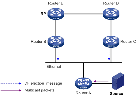
As shown in Figure 37, without the DF election mechanism, both Router B and Router C can receive multicast packets from Route A. They also can forward the packets to downstream routers on the local subnet. As a result, the RP (Router E) receives duplicate multicast packets.
With the DF election mechanism, once receiving the RP information, Router B and Router C multicast a DF election message to all PIM routers (224.0.0.13) to initiate a DF election process. The election message carries the RP's address, and the route preference and the metric of the unicast route or static multicast route to the RP. A DF is elected as follows:
1. The router with a higher route preference becomes the DF.
2. If the routers have the same route preference, the router with a lower metric becomes the DF.
3. If the routers have the same metric, the router with a higher IP address becomes the DF.
Bidirectional RPT building
Figure 38 RPT building at the receiver side

As shown in Figure 38, the process for building a receiver-side RPT is the same as the process for building an RPT in PIM-SM:
1. When a receiver wants to join the multicast group G, it uses an IGMP message to inform the directly connected router.
2. After receiving the message, the router sends a join message, which is forwarded hop by hop to the RP for the multicast group.
3. The routers along the path from the receiver's directly connected router to the RP form an RPT branch. Each router on this branch adds a (*, G) entry to its forwarding table.
After a receiver host leaves the multicast group G, the directly connected router multicasts a prune message to all PIM routers on the subnet. The prune message goes hop by hop along the reverse direction of the RPT to the RP. After receiving the prune message, an upstream node removes the interface that connects to the downstream node from the outgoing interface list. At the same time, the upstream router checks the existence of receivers for that multicast group. If no receivers for the multicast group exist, the router continues to forward the prune message to its upstream router.
Figure 39 RPT building at the multicast source side
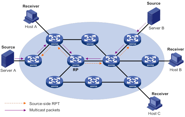
As shown in Figure 39, the process for building a source-side RPT is relatively simple:
4. When a multicast source sends multicast packets to the multicast group G, the DF in each subnet unconditionally forwards the packets to the RP.
5. The routers along the path from the source's directly connected router to the RP constitute an RPT branch. Each router on this branch adds to its forwarding table a (*, G) entry.
After a bidirectional RPT is built, the multicast sources send multicast traffic to the RP along the source-side RPT. Then, the RP forwards the traffic to the receivers along the receiver-side RPT.
|
|
IMPORTANT: If a receiver and a multicast source are at the same side of the RP, the source-side RPT and the receiver-side RPT might meet at a node before reaching the RP. In this case, the multicast packets from the multicast source to the receiver are directly forwarded by the node, instead of by the RP. |
Administrative scoping overview
Typically, a PIM-SM domain or a BIDIR-PIM domain contains only one BSR, which is responsible for advertising RP-set information within the entire domain. The information about all multicast groups is forwarded within the network that the BSR administers. This is called the "non-scoped BSR mechanism."
Administrative scoping mechanism
To implement refined management, you can divide a PIM-SM domain or BIDIR-PIM domain into a global-scoped zone and multiple administratively-scoped zones (admin-scoped zones). This is called the "administrative scoping mechanism."
The administrative scoping mechanism effectively releases stress on the management in a single-BSR domain and enables provision of zone-specific services through private group addresses.
Admin-scoped zones are divided for multicast groups. Zone border routers (ZBRs) form the boundary of an admin-scoped zone. Each admin-scoped zone maintains one BSR for multicast groups within a specific range. Multicast protocol packets, such as assert messages and BSMs, for a specific group range cannot cross the boundary of the admin-scoped zone for the group range. Multicast group ranges that are associated with different admin-scoped zones can have intersections. However, the multicast groups in an admin-scoped zone are valid only within the local zone, and theses multicast groups are regarded as private group addresses.
The global-scoped zone maintains a BSR for the multicast groups that do not belong to any admin-scoped zones.
Relationship between admin-scoped zones and the global-scoped zone
The global-scoped zone and each admin-scoped zone have their own C-RPs and BSRs. These devices are effective only on their respective zones, and the BSR election and the RP election are implemented independently. Each admin-scoped zone has its own boundary. The multicast information within a zone cannot cross this boundary in either direction. You can have a better understanding of the global-scoped zone and admin-scoped zones based on geographical locations and multicast group address ranges.
· In view of geographical locations:
An admin-scoped zone is a logical zone for particular multicast groups. The multicast packets for such multicast groups are confined within the local admin-scoped zone and cannot cross the boundary of the zone.
Figure 40 Relationship in view of geographical locations
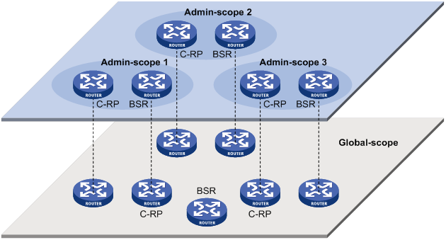
As shown in Figure 40, for the multicast groups in a specific group address range, the admin-scoped zones must be geographically separated and isolated. A router cannot belong to multiple admin-scoped zones. An admin-scoped zone cannot contain a router that belongs to any other admin-scoped zone. However, the global-scoped zone includes all routers in the PIM-SM domain or BIDIR-PIM domain. Multicast packets that do not belong to any admin-scoped zones are forwarded in the entire PIM-SM domain or BIDIR-PIM domain.
· In view of multicast group address ranges:
Each admin-scoped zone is designated to specific multicast groups, of which the multicast group addresses are valid only within the local zone. The multicast groups of different admin-scoped zones might have intersections. All the multicast groups other than those of the admin-scoped zones use the global-scoped zone.
Figure 41 Relationship in view of multicast group address ranges
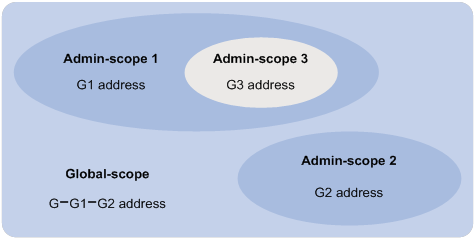
As shown in Figure 41, the admin-scoped zones 1 and 2 have no intersection, but the admin-scoped zone 3 is a subset of the admin-scoped zone 1. The global-scoped zone provides services for all the multicast groups that are not covered by the admin-scoped zones 1 and 2, G−G1−G2 in this case.
PIM-SSM overview
The ASM model includes PIM-DM and PIM-SM. The SSM model can be implemented by leveraging part of the PIM-SM technique. It is also called "PIM-SSM."
The SSM model provides a solution for source-specific multicast. It maintains the relationship between hosts and routers through IGMPv3.
In actual applications, part of IGMPv3 and PIM-SM techniques are adopted to implement the SSM model. In the SSM model, because receivers have located a multicast source, no RP or RPT is required. Multicast sources do not register with the RP, and the MSDP is not needed for discovering multicast sources in other PIM domains.
Neighbor discovery
PIM-SSM uses the same neighbor discovery mechanism as PIM-SM. For more information, see "Neighbor discovery."
DR election
PIM-SSM uses the same DR election mechanism as PIM-SM. For more information, see "DR election."
SPT building
The decision to build an RPT for PIM-SM or an SPT for PIM-SSM depends on whether the multicast group that the receiver joins is in the SSM group range. The SSM group range reserved by IANA is 232.0.0.0/8.
Figure 42 SPT building in PIM-SSM
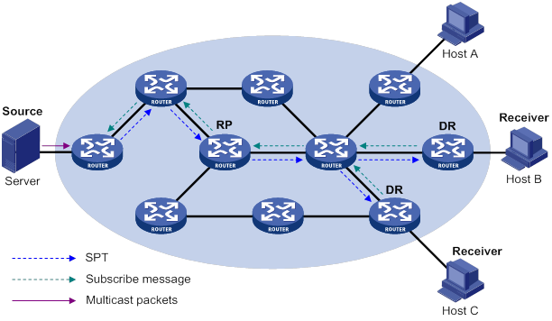
As shown in Figure 42, Host B and Host C are receivers. They send IGMPv3 report messages to their DRs to express their interest in the multicast information that the multicast source S sends to the multicast group G.
After receiving a report message, the DR first checks whether the group address in this message is in the SSM group range and does the following:
· If the group address is in the SSM group range, the DR sends a subscribe message hop by hop toward the multicast source S. All routers along the path from the DR to the source create an (S, G) entry to build an SPT. The SPT is rooted at the multicast source S and has the receivers as its leaves. This SPT is the transmission channel in PIM-SSM.
· If the group address is not in the SSM group range, the receiver-side DR sends a (*, G) join message to the RP. The multicast source registers with the source-side DR.
In PIM-SSM, the term "subscribe message" refers to a join message.
Relationship among PIM protocols
In a PIM network, PIM-DM cannot run together with PIM-SM, BIDIR-PIM, or PIM-SSM. However, PIM-SM, BIDIR-PIM, and PIM-SSM can run together. Figure 43 shows how the device selects one protocol from among them for a receiver trying to join a group.
For more information about IGMP SSM mapping, see "Configuring IGMP."
Figure 43 Relationship among PIM protocols
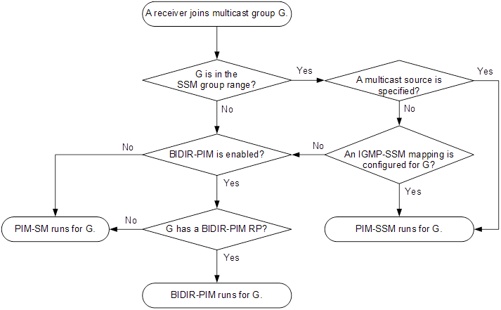
PIM support for VPNs
To support PIM for VPNs, a multicast router that runs PIM maintains an independent set of PIM neighbor table, multicast routing table, BSR information, and RP-set information for each VPN.
After receiving a multicast data packet, the multicast router checks which VPN the data packet belongs to. Then, the router forwards the packet according to the multicast routing table for that VPN or creates a multicast routing entry for that VPN.
Protocols and standards
· RFC 3973, Protocol Independent Multicast-Dense Mode (PIM-DM): Protocol Specification(Revised)
· RFC 4601, Protocol Independent Multicast-Sparse Mode (PIM-SM): Protocol Specification (Revised)
· RFC 4610, Anycast-RP Using Protocol Independent Multicast (PIM)
· RFC 5015, Bidirectional Protocol Independent Multicast (BIDIR-PIM)
· RFC 5059, Bootstrap Router (BSR) Mechanism for Protocol Independent Multicast (PIM)
· RFC 4607, Source-Specific Multicast for IP
· Draft-ietf-ssm-overview-05, An Overview of Source-Specific Multicast (SSM)
Feature and hardware compatibility
The following matrix shows the feature and hardware compatibility:
|
Hardware |
PIM compatibility |
|
MSR810/810-W/810-W-DB/810-LM/810-W-LM/810-10-PoE/810-LM-HK/810-W-LM-HK |
Yes |
|
MSR810-LMS/810-LUS |
No |
|
MSR2600-6-X1/2600-10-X1 |
Yes |
|
MSR 2630 |
Yes |
|
MSR3600-28/3600-51 |
Yes |
|
MSR3600-28-SI/3600-51-SI |
No |
|
MSR3610-X1/3610-X1-DP/3610-X1-DC/3610-X1-DP-DC |
Yes |
|
MSR 3610/3620/3620-DP/3640/3660 |
Yes |
|
MSR5620/5660/5680 |
Yes |
|
Hardware |
PIM compatibility |
|
MSR810-LM-GL |
Yes |
|
MSR810-W-LM-GL |
Yes |
|
MSR830-6EI-GL |
Yes |
|
MSR830-10EI-GL |
Yes |
|
MSR830-6HI-GL |
Yes |
|
MSR830-10HI-GL |
Yes |
|
MSR2600-6-X1-GL |
Yes |
|
MSR3600-28-SI-GL |
No |
Configuring PIM-DM
This section describes how to configure PIM-DM.
PIM-DM configuration task list
|
Tasks at a glance |
|
(Required.) Enabling PIM-DM |
|
(Optional.) Enabling the state refresh feature |
|
(Optional.) Configuring state refresh parameters |
|
(Optional.) Configuring PIM-DM graft retry timer |
|
(Optional.) Configuring common PIM features |
Configuration prerequisites
Before you configure PIM-DM, configure a unicast routing protocol so that all devices in the domain can interoperate at the network layer.
Enabling PIM-DM
Enable IP multicast routing before you configure PIM.
With PIM-DM enabled on interfaces, routers can establish PIM neighbor relationship and process PIM messages from their PIM neighbors. As a best practice, enable PIM-DM on all non-border interfaces of routers when you deploy a PIM-DM domain.
|
|
IMPORTANT: All the interfaces on a device must operate in the same PIM mode in the public network or the same VPN instance. |
To enable PIM-DM:
|
Step |
Command |
Remarks |
|
1. Enter system view. |
system-view |
N/A |
|
2. Enable IP multicast routing and enter MRIB view. |
multicast routing [ vpn-instance vpn-instance-name ] |
By default, IP multicast routing is disabled. |
|
3. Return to system view. |
quit |
N/A |
|
4. Enter interface view. |
interface interface-type interface-number |
N/A |
|
5. Enable PIM-DM. |
pim dm |
By default, PIM-DM is disabled. |
Enabling the state refresh feature
In a PIM-DM domain, the state refresh feature enables the PIM router that is directly connected to the source to periodically send state refresh messages. It also enables other PIM routers to refresh pruned state timers after receiving the state refresh messages. It prevents the pruned interfaces from resuming multicast forwarding. You must enable this feature on all PIM routers on a subnet.
To enable the state refresh feature:
|
Step |
Command |
Remarks |
|
1. Enter system view. |
system-view |
N/A |
|
2. Enter interface view. |
interface interface-type interface-number |
N/A |
|
3. Enable the state refresh feature. |
pim state-refresh-capable |
By default, the state refresh feature is enabled. |
Configuring state refresh parameters
The state refresh interval determines the interval at which a router sends state refresh messages. It is configurable.
A router might receive duplicate state refresh messages within a short time. To prevent this situation, you can configure the time that the router must wait to accept a new state refresh message. If the router receives a new state refresh message before the timer expires, it discards the message. If the router receives a new state refresh message after the timer expires, it accepts the message, refreshes its own PIM-DM state, and resets the waiting timer.
The TTL value of a state refresh message decrements by 1 whenever it passes a router before it is forwarded to the downstream node. The state refresh message stops being forwarded when the TTL value comes down to 0. A state refresh message with a large TTL value might cycle on a small network. To effectively control the propagation scope of state refresh messages, configure an appropriate TTL value based on the network size on the router directly connected with the multicast source.
To configure state refresh parameters:
|
Step |
Command |
Remarks |
|
1. Enter system view. |
system-view |
N/A |
|
2. Enter PIM view. |
pim [ vpn-instance vpn-instance-name ] |
N/A |
|
3. Configure the state refresh interval. |
state-refresh-interval interval |
The default setting is 60 seconds. |
|
4. Configure the amount of time to wait before accepting a new state refresh message. |
state-refresh-rate-limit time |
The default setting is 30 seconds. |
|
5. Configure the TTL value of state refresh messages. |
state-refresh-ttl ttl-value |
The default setting 255. |
Configuring PIM-DM graft retry timer
To configure the graft retry timer:
|
Step |
Command |
Remarks |
|
1. Enter system view. |
system-view |
N/A |
|
2. Enter interface view. |
interface interface-type interface-number |
N/A |
|
3. Configure the graft retry timer. |
pim timer graft-retry interval |
The default setting is 3 seconds. |
For more information about the configuration of other timers in PIM-DM, see "Configuring common PIM timers."
Configuring PIM-SM
This section describes how to configure PIM-SM.
PIM-SM configuration task list
|
Tasks at a glance |
Remarks |
|
(Required.) Enabling PIM-SM |
N/A |
|
(Required.) Configuring an RP: · (Optional.) Enabling Auto-RP listening · (Optional.) Configuring Anycast RP |
You must configure a static RP, a C-RP, or both in a PIM-SM domain. |
|
· (Required.) Configuring a C-BSR · (Optional.) Configuring a PIM domain border · (Optional.) Disabling BSM semantic fragmentation · (Optional.) Disabling BSM forwarding out of incoming interfaces |
Skip the task of configuring a BSR on a network without C-RPs. |
|
(Optional.) Configuring multicast source registration |
N/A |
|
(Optional.) Configuring the switchover to SPT |
N/A |
|
(Optional.) Configuring common PIM features |
N/A |
Configuration prerequisites
Before you configure PIM-SM, configure a unicast routing protocol so that all devices in the domain can interoperate at the network layer.
Enabling PIM-SM
Enable IP multicast routing before you configure PIM.
With PIM-SM enabled on interfaces, routers can establish PIM neighbor relationship and process PIM messages from their PIM neighbors. As a best practice, enable PIM-SM on all non-border interfaces of routers when you deploy a PIM-SM domain.
|
|
IMPORTANT: All the interfaces on the same router must operate in the same PIM mode in the public network or the same VPN instance. |
To enable PIM-SM:
|
Step |
Command |
Remarks |
|
1. Enter system view. |
system-view |
N/A |
|
2. Enable IP multicast routing and enter MRIB view. |
multicast routing [ vpn-instance vpn-instance-name ] |
By default, IP multicast routing is disabled. |
|
3. Return to system view. |
quit |
N/A |
|
4. Enter interface view. |
interface interface-type interface-number |
N/A |
|
5. Enable PIM-SM. |
pim sm |
By default, PIM-SM is disabled. |
Configuring an RP
An RP can provide services for multiple or all multicast groups. However, only one RP can forward multicast traffic for a multicast group at a time.
An RP can be manually configured or dynamically elected through the BSR mechanism. For a large-scaled PIM network, configuring static RPs is a tedious job. Generally, static RPs are backups for dynamic RPs to enhance the robustness and operational manageability on a multicast network.
Configuring a static RP
If only one dynamic RP exists on a network, you can configure a static RP to avoid communication interruption caused by single-point failures. The static RP can also avoid waste of bandwidth due to frequent message exchange between C-RPs and the BSR.
When you configure static RPs for PIM-SM, follow these restrictions and guidelines:
· You can configure the same static RP for different multicast groups by using the same RP address but different ACLs.
· You do not need to enable PIM for an interface to be configured as a static RP.
· If you configure multiple static RPs for a multicast group, only the static RP with the highest IP address takes effect.
· The static RP configuration must be the same on all routers in the PIM-SM domain.
To configure a static RP for PIM-SM:
|
Step |
Command |
Remarks |
|
1. Enter system view. |
system-view |
N/A |
|
2. Enter PIM view. |
pim [ vpn-instance vpn-instance-name ] |
N/A |
|
3. Configure a static RP for PIM-SM. |
static-rp rp-address [ ipv4-acl-number | preferred ] * |
By default, no static RPs exist. |
Configuring a C-RP
|
|
IMPORTANT: When you configure a C-RP, reserve a relatively large bandwidth between the C-RP and other devices in the PIM-SM domain. |
In a PIM-SM domain, if you want a router to become the RP, you can configure the router as a C-RP. As a best practice, configure C-RPs on backbone routers.
The C-RPs periodically send advertisement messages to the BSR, which collects RP-set information for RP election. You can configure the interval for sending the advertisement messages.
The holdtime option in C-RP advertisement messages defines the C-RP lifetime for the advertising C-RP. The BSR starts a holdtime timer for a C-RP after it receives an advertisement message. If the BSR does not receive any advertisement message when the timer expires, it considers the C-RP failed or unreachable.
A C-RP policy enables the BSR to filter C-RP advertisement messages by using an ACL that specifies the packet source address range and multicast groups. It is used to guard against C-RP spoofing. You must configure the same C-RP policy on all C-BSRs in the PIM-SM domain.
To configure a C-RP:
|
Step |
Command |
Remarks |
|
1. Enter system view. |
system-view |
N/A |
|
2. Enter PIM view. |
pim [ vpn-instance vpn-instance-name ] |
N/A |
|
3. Configure a C-RP. |
c-rp ip-address [ advertisement-interval adv-interval | group-policy ipv4-acl-number | holdtime hold-time | priority priority ] * |
By default, no C-RPs exist. |
|
4. (Optional.) Configure a C-RP policy. |
crp-policy ipv4-acl-number |
By default, no C-RP policies exist, and all C-RP advertisement messages are regarded legal. |
Enabling Auto-RP listening
This feature enables the device to receive Auto-RP announcement and discovery messages and learn RP information. The destination IP addresses for Auto-RP announcement and discovery messages are 224.0.1.39 and 224.0.1.40, respectively.
To enable Auto-RP listening:
|
Step |
Command |
Remarks |
|
1. Enter system view. |
system-view |
N/A |
|
2. Enter PIM view. |
pim [ vpn-instance vpn-instance-name ] |
N/A |
|
3. Enable Auto-RP listening. |
auto-rp enable |
By default, Auto-RP listening is disabled. |
Configuring Anycast RP
|
|
IMPORTANT: The Anycast RP address must be different from the BSR address. Otherwise, the other Anycast RP member devices will discard the BSM sent by the BSR. |
You must configure a static RP or C-RPs in the PIM-SM domain before you configure the Anycast RP. Use the address of the static RP or the dynamically elected RP as the Anycast RP address.
When you configure Anycast RP, follow these restrictions and guidelines:
· You must add the device that the Anycast RP resides as an RP member to the Anycast RP set. The RP member address cannot be the same as the Anycast RP address.
· You must add all RP member addresses (including the local RP member address) to the Anycast RP set on each RP member device.
· As a best practice, configure no more than 16 Anycast RP members for an Anycast RP set.
· As a best practice, configure the loopback interface address of an RP member device as the RP member address. If you add multiple interface addresses of an RP member device to an Anycast RP set, the lowest IP address becomes the RP member address. The rest of the interface addresses become backup RP member addresses.
To configure Anycast RP:
|
Step |
Command |
Remarks |
|
1. Enter system view. |
N/A |
|
|
2. Enter PIM view. |
N/A |
|
|
3. Configure Anycast RP. |
By default, Anycast RP is not configured. You can repeat this command to add multiple RP member addresses to the Anycast RP set. |
Configuring a BSR
You must configure a BSR if C-RPs are configured to dynamically select the RP. You do not need to configure a BSR when you have configured only a static RP but no C-RPs.
A PIM-SM domain can have only one BSR, but must have a minimum of one C-BSR. Any router can be configured as a C-BSR. Elected from C-BSRs, the BSR is responsible for collecting and advertising RP information in the PIM-SM domain.
Configuring a C-BSR
The BSR election process is summarized as follows:
1. Initially, each C-BSR regards itself as the BSR of the PIM-SM domain and sends a BSM to other routers in the domain.
2. When a C-BSR receives the BSM from another C-BSR, it compares its own priority with the priority carried in the message. The C-BSR with a higher priority wins the BSR election. If a tie exists in the priority, the C-BSR with a higher IP address wins. The loser uses the winner's BSR address to replace its own BSR address and no longer regards itself as the BSR. The winner retains its own BSR address and continues to regard itself as the BSR.
The elected BSR distributes the RP-set information collected from C-RPs to all routers in the PIM-SM domain. All routers use the same hash algorithm to select an RP for a specific multicast group.
A BSR policy enables a PIM-SM router to filter BSR messages by using an ACL that specifies the legal BSR addresses. It is used to guard against the following BSR spoofing cases:
· Some maliciously configured hosts can forge BSMs to fool routers and change RP mappings. Such attacks often occur on border routers.
· When an attacker controls a router on the network, the attacker can configure the router as a C-BSR to win the BSR election. Through this router, the attacker controls the advertising of RP information.
When you configure a C-BSR, follow these restrictions and guidelines:
· Configure C-BSRs on routers that are on the backbone network.
· Reserve a relatively large bandwidth between the C-BSR and the other devices in the PIM-SM domain.
· You must configure the same BSR policy on all routers in the PIM-SM domain. The BSR policy discards illegal BSR messages, but it partially guards against BSR attacks on the network. If an attacker controls a legal BSR, the problem still exists.
· When C-BSRs connect to other PIM routers through tunnels, static multicast routes must be configured to make sure the next hop to a C-BSR is a tunnel interface. Otherwise, RPF check is affected. For more information about static multicast routes, see "Configuring multicast routing and forwarding."
To configure a C-BSR:
|
Step |
Command |
Remarks |
|
1. Enter system view. |
system-view |
N/A |
|
2. Enter PIM view. |
pim [ vpn-instance vpn-instance-name ] |
N/A |
|
3. Configure a C-BSR. |
c-bsr ip-address [ scope group-address { mask-length | mask } ] [ hash-length hash-length | priority priority ] * |
By default, no C-BSRs exist. |
|
4. (Optional.) Configure a BSR policy. |
bsr-policy ipv4-acl-number |
By default, no BSR policies exist, and all bootstrap messages are regarded legal. |
Configuring a PIM domain border
A PIM domain border determines the transmission boundary of bootstrap messages. Bootstrap messages cannot cross the domain border in either direction. A number of PIM domain border interfaces partition a network into different PIM-SM domains.
To configure a PIM domain border:
|
Step |
Command |
Remarks |
|
1. Enter system view. |
system-view |
N/A |
|
2. Enter interface view. |
interface interface-type interface-number |
N/A |
|
3. Configure a PIM domain border. |
pim bsr-boundary |
By default, an interface is not a PIM domain border. |
Disabling BSM semantic fragmentation
BSM semantic fragmentation enables a BSR to split a BSM into multiple BSM fragments (BSMFs) if the BSM exceeds the MTU. In this way, a non-BSR router can update the RP-set information for a group range after receiving all BSMFs for the range. The loss of one BSMF only affects the RP-set information of the group ranges that the fragment contains.
If the PIM-SM domain contains a device that does not support this feature, you must disable this feature on all C-BSRs. If you do not disable this feature, such a device regards a BSMF as a BSM and updates the RP-set information each time it receives a BSMF. It learns only part of the RP-set information, which further affects the RP election.
To disable BSM semantic fragmentation:
|
Step |
Command |
Remarks |
|
1. Enter system view. |
system-view |
N/A |
|
2. Enter PIM view. |
pim [ vpn-instance vpn-instance-name ] |
N/A |
|
3. Disable BSM semantic fragmentation. |
undo bsm-fragment enable |
By default, BSM semantic fragmentation is enabled. |
|
|
NOTE: Generally, a BSR performs BSM semantic fragmentation according to the MTU of its BSR interface. For BSMs originated due to learning of a new PIM neighbor, semantic fragmentation is performed according to the MTU of the interface that sends the BSMs. |
Disabling BSM forwarding out of incoming interfaces
By default, the device is enabled to forward BSMs out of incoming interfaces. This feature avoids devices in the PIM-SM domain might from failing to receive BSMs due to inconsistent routing information. To reduce traffic, you can disable this feature if all the devices have consistent routing information.
To disable the device from sending BSMs out of incoming interfaces:
|
Step |
Command |
Remarks |
|
1. Enter system view. |
system-view |
N/A |
|
2. Enter PIM view. |
pim [ vpn-instance vpn-instance-name ] |
N/A |
|
3. Disable the device from sending BSMs out of incoming interfaces. |
undo bsm-reflection enable |
By default, the device is enabled to forward BSMs out of incoming interfaces. |
Configuring multicast source registration
You can configure the device to calculate the checksum based on the entire register message to ensure information integrity of a register message in the transmission process. If a device that does not support this feature is present on the network, you can configure the device to calculate the checksum based on the register message header.
The RP sends a register-stop message to the source-side DR in either of the following conditions:
· The RP stops serving the receivers for a multicast group. The receivers do not receive multicast data addressed to the multicast group through the RP.
· The RP receives multicast data that travels along the SPT.
After receiving the register-stop message, the DR stops sending register messages encapsulated with multicast data and starts a register-stop timer. Before the register-stop timer expires, the DR sends a null register message (a register message without encapsulated multicast data) to the RP and starts a register probe timer. If the DR receives a register-stop message before the register probe timer expires, it resets its register-stop timer. Otherwise, the DR starts sending register messages with encapsulated data again.
The register-stop timer is set to a random value chosen uniformly from (0.5 × register_suppression_time minus register_probe_time) to (1.5 × register_suppression_time minus register_probe_time). The register_probe_time is fixed to 5 seconds.
On all C-RP routers, perform the following tasks:
· Configure a PIM register policy.
· Configure the routers to calculate the checksum based on the entire register messages or the register message header.
On all routers that might become the source-side DR, configure the register suppression time.
To configure multicast source registration:
|
Step |
Command |
Remarks |
|
1. Enter system view. |
system-view |
N/A |
|
2. Enter PIM view. |
pim [ vpn-instance vpn-instance-name ] |
N/A |
|
3. Configure a PIM register policy. |
register-policy ipv4-acl-number |
By default, no PIM register policies exist, and all PIM register messages are regarded legal. |
|
4. Configure the device to calculate the checksum based on the entire register message. |
register-whole-checksum |
By default, the device calculates the checksum based on the header of a register message. |
|
5. Configure the register suppression time. |
The default setting is 60 seconds. |
Configuring the switchover to SPT
|
|
CAUTION: If the device is an RP, disabling the switchover to SPT might cause multicast traffic forwarding failures on the source-side DR. When disabling the switchover to SPT, make sure you fully understand its impact on your network. |
Both the receiver-side DR and RP can monitor the traffic rate of passing-by multicast packets and thus trigger a switchover from RPT to SPT. The monitor function is not available on switches.
To configure the switchover to SPT:
|
Step |
Command |
Remarks |
|
1. Enter system view. |
system-view |
N/A |
|
2. Enter PIM view. |
pim [ vpn-instance vpn-instance-name ] |
N/A |
|
3. Configure the RPT to SPT switchover. |
spt-switch-threshold { traffic-rate | immediacy | infinity } [ group-policy ipv4-acl-number ] |
By default, the first multicast data packet triggers the RPT to SPT switchover. The traffic-rate argument is not supported on switches. |
|
|
NOTE: If the multicast source information is learned through MSDP, the device switches to SPT immediately after it receives the first multicast packet, regardless of the traffic rate threshold. |
Configuring BIDIR-PIM
This section describes how to configure BIDIR-PIM.
BIDIR-PIM configuration task list
|
Tasks at a glance |
Remarks |
|
(Required.) Enabling BIDIR-PIM |
N/A |
|
(Required.) Configuring an RP: · (Optional.) Enabling Auto-RP listening · (Optional.) Setting the maximum number of BIDIR-PIM RPs |
You must configure a static RP, a C-RP, or both in a BIDIR-PIM domain. |
|
· (Required.) Configuring a C-BSR · (Optional.) Configuring a PIM domain border · (Optional.) Disabling BSM semantic fragmentation · (Optional.) Disabling BSM forwarding out of incoming interfaces |
Skip the task of configuring a BSR on a network without C-RPs. |
|
(Optional.) Configuring common PIM features |
N/A |
Configuration prerequisites
Before you configure BIDIR-PIM, configure a unicast routing protocol so that all devices in the domain can interoperate at the network layer.
Enabling BIDIR-PIM
Because BIDIR-PIM is implemented on the basis of PIM-SM, you must enable PIM-SM before you enable BIDIR-PIM. As a best practice, enable PIM-SM on all non-border interfaces of routers when you deploy a BIDIR-PIM domain.
|
|
IMPORTANT: All interfaces on a device must be enabled with the same PIM mode. |
To enable BIDIR-PIM:
|
Step |
Command |
Remarks |
|
1. Enter system view. |
system-view |
N/A |
|
2. Enable IP multicast routing and enter MRIB view. |
multicast routing [ vpn-instance vpn-instance-name ] |
By default, IP multicast routing is disabled. |
|
3. Return to system view. |
quit |
N/A |
|
4. Enter interface view. |
interface interface-type interface-number |
N/A |
|
5. Enable PIM-SM. |
pim sm |
By default, PIM-SM is disabled. |
|
6. Return to system view. |
quit |
N/A |
|
7. Enter PIM view. |
pim [ vpn-instance vpn-instance-name ] |
N/A |
|
8. Enable BIDIR-PIM. |
bidir-pim enable |
By default, BIDIR-PIM is disabled. |
Configuring an RP
|
|
CAUTION: When both PIM-SM and BIDIR-PIM run on the PIM network, do not use the same RP to provide services for PIM-SM and BIDIR-PIM. Otherwise, exceptions might occur to the PIM routing table. |
An RP can provide services for multiple or all multicast groups. However, only one RP can forward multicast traffic for a multicast group at a time.
An RP can be manually configured or dynamically elected through the BSR mechanism. For a large-scaled PIM network, configuring static RPs is a tedious job. Generally, static RPs are backups for dynamic RPs to enhance the robustness and operational manageability on a multicast network.
Configuring a static RP
If only one dynamic RP exists on a network, you can configure a static RP to avoid communication interruption caused by single-point failures. The static RP also avoids bandwidth waste due to frequent message exchange between C-RPs and the BSR.
In BIDIR-PIM, a static RP can be specified with an unassigned IP address. This address must be on the same subnet with the link on which the static RP is configured. For example, if the IP addresses of the interfaces at the two ends of a link are 10.1.1.1/24 and 10.1.1.2/24, you can assign 10.1.1.100/24 to the static RP. As a result, the link becomes an RPL.
When you configure static RPs for BIDIR-PIM, follow these restrictions and guidelines:
· You can configure the same static RP for different multicast groups by using the same RP address but different ACLs.
· You do not need to enable PIM for an interface to be configured as a static RP.
· If you configure multiple static RPs for a multicast group, only the static RP with the highest IP address takes effect.
· The static RP configuration must be the same on all routers in the BIDIR-PIM domain.
To configure a static RP:
|
Step |
Command |
Remarks |
|
1. Enter system view. |
system-view |
N/A |
|
2. Enter PIM view. |
pim [ vpn-instance vpn-instance-name ] |
N/A |
|
3. Configure a static RP for BIDIR-PIM. |
static-rp rp-address bidir [ ipv4-acl-number | preferred ] * |
By default, no static RPs exist. |
Configuring a C-RP
|
|
IMPORTANT: When you configure a C-RP, reserve a large bandwidth between the C-RP and other devices in the BIDIR-PIM domain. |
In a BIDIR-PIM domain, if you want a router to become the RP, you can configure the router as a C-RP. The BSR collects the C-RP information according to the received advertisement messages from C-RPs or the auto-RP announcements from other routers. Then, it organizes the C-RP information into the RP-set information, which is flooded throughout the entire network. Then, the other routers on the network can determine the RPs for different multicast group ranges based on the RP-set information. As a best practice, configure C-RPs on backbone routers.
To enable the BSR to distribute the RP-set information in the BIDIR-PIM domain, the C-RPs must periodically send advertisement messages to the BSR. The BSR learns the C-RP information, encapsulates the C-RP information and its own IP address in a BSM, and floods the BSM to all PIM routers in the domain.
An advertisement message contains a holdtime option, which defines the C-RP lifetime for the advertising C-RP. After the BSR receives an advertisement message from a C-RP, it starts a timer for the C-RP. If the BSR does not receive any advertisement message when the timer expires, it considers the C-RP failed or unreachable.
To configure a C-RP:
|
Step |
Command |
Remarks |
|
1. Enter system view. |
system-view |
N/A |
|
2. Enter PIM view. |
pim [ vpn-instance vpn-instance-name ] |
N/A |
|
3. Configure a C-RP to provide services for BIDIR-PIM. |
c-rp ip-address [ advertisement-interval adv-interval | group-policy ipv4-acl-number | holdtime hold-time | priority priority ] * bidir |
By default, no C-RPs exist. |
Enabling Auto-RP listening
This feature enables the device to receive Auto-RP announcement and discovery messages and learn RP information. The destination IP addresses for Auto-RP announcement and discovery messages are 224.0.1.39 and 224.0.1.40, respectively.
To enable Auto-RP listening:
|
Step |
Command |
Remarks |
|
1. Enter system view. |
system-view |
N/A |
|
2. Enter PIM view. |
pim [ vpn-instance vpn-instance-name ] |
N/A |
|
3. Enable Auto-RP listening. |
auto-rp enable |
By default, Auto-RP listening is disabled. |
Setting the maximum number of BIDIR-PIM RPs
In a BIDIR-PIM domain, one DF election per RP is implemented on all PIM-enabled interfaces. As a best practice, do not configure multiple BIDIR-PIM RPs to avoid unnecessary DF elections.
This configuration sets a limit on the number of BIDIR-PIM RPs. If the number of RPs exceeds the limit, excess RPs do not take effect and can be used only for DF election rather than multicast data forwarding. The system does not delete the excess RPs. They must be deleted manually.
To set the maximum number of BIDIR-PIM RPs:
|
Step |
Command |
Remarks |
|
1. Enter system view. |
system-view |
N/A |
|
2. Enter PIM view. |
pim [ vpn-instance vpn-instance-name ] |
N/A |
|
3. Set the maximum number of BIDIR-PIM RPs. |
bidir-rp-limit limit |
By default, the maximum number of BIDIR-PIM RPs is 6. |
Configuring a BSR
You must configure a BSR if C-RPs are configured to dynamically select the RP. You do not need to configure a BSR when you have configured only a static RP but no C-RPs.
A BIDIR-PIM domain can have only one BSR, but must have a minimum of one C-BSR. Any router can be configured as a C-BSR. Elected from C-BSRs, the BSR is responsible for collecting and advertising RP information in the BIDIR-PIM domain.
Configuring a C-BSR
|
|
IMPORTANT: Because the BSR and other devices exchange a large amount of information in the BIDIR-PIM domain, reserve a large bandwidth between the C-BSR and other devices. |
The BSR election process is summarized as follows:
1. Initially, each C-BSR regards itself as the BSR of the BIDIR-PIM domain and sends BSMs to other routers in the domain.
2. When a C-BSR receives the BSM from another C-BSR, it compares its own priority with the priority carried in the message. The C-BSR with a higher priority wins the BSR election. If a tie exists in the priority, the C-BSR with a higher IP address wins. The loser uses the winner's BSR address to replace its own BSR address and no longer regards itself as the BSR. The winner retains its own BSR address and continues to regard itself as the BSR.
The elected BSR distributes the RP-set information collected from C-RPs to all routers in the BIDIR-PIM domain. All routers use the same hash algorithm to select an RP for a specific multicast group.
A BSR policy enables the router to filter BSR messages by using an ACL that specifies the legal BSR addresses. It is used to guard against the following BSR spoofing cases:
· Some maliciously configured hosts can forge BSMs to fool routers and change RP mappings. Such attacks often occur on border routers.
· When an attacker controls a router on the network, the attacker can configure the router as a C-BSR to win the BSR election. Through this router, the attacker controls the advertising of RP information.
When you configure a C-BSR, follow these restrictions and guidelines:
· C-BSRs should be configured on routers on the backbone network.
· You must configure the same BSR policy on all routers in the BIDIR-PIM domain. The BSR policy discards illegal BSR messages, but it partially guards against BSR attacks on the network. If an attacker controls a legal BSR, the problem still exists.
· For C-BSRs interconnected through a GRE tunnel, configure static multicast routes to make sure the next hop to a C-BSR is a tunnel interface. For more information about static multicast routes, see "Configuring multicast routing and forwarding."
To configure a C-BSR:
|
Step |
Command |
Remarks |
|
1. Enter system view. |
system-view |
N/A |
|
2. Enter PIM view. |
pim [ vpn-instance vpn-instance-name ] |
N/A |
|
3. Configure a C-BSR. |
c-bsr ip-address [ scope group-address { mask-length | mask } ] [ hash-length hash-length | priority priority ] * |
By default, no C-BSRs exist. |
|
4. (Optional.) Configure a BSR policy. |
bsr-policy ipv4-acl-number |
By default, no BSR policies exist, and all bootstrap messages are regarded legal. |
Configuring a PIM domain border
A PIM domain border determines the transmission boundary of bootstrap messages. Bootstrap messages cannot cross the domain border in either direction. A number of PIM domain border interfaces partition a network into different BIDIR-PIM domains.
To configure a PIM domain border:
|
Step |
Command |
Remarks |
|
1. Enter system view. |
system-view |
N/A |
|
2. Enter interface view. |
interface interface-type interface-number |
N/A |
|
3. Configure a PIM domain border. |
pim bsr-boundary |
By default, an interface is not a PIM domain border. |
Disabling BSM semantic fragmentation
BSM semantic fragmentation enables a BSR to split a BSM into multiple BSM fragments (BSMFs) if the BSM exceeds the MTU. In this way, a non-BSR router can update the RP-set information for a group range after receiving all BSMFs for the group range. The loss of one BSMF only affects the RP-set information of the group ranges that the fragment contains.
If the BIDIR-SM domain contains a device that does not support this feature, you must disable this feature on all C-BSRs. If you do not disable this feature, such a device regards a BSMF as a BSM and updates the RP-set information each time it receives a BSMF. It learns only part of the RP-set information, which further affects the RP election.
To disable BSM semantic fragmentation:
|
Step |
Command |
Remarks |
|
1. Enter system view. |
system-view |
N/A |
|
2. Enter PIM view. |
pim [ vpn-instance vpn-instance-name ] |
N/A |
|
3. Disable BSM semantic fragmentation. |
undo bsm-fragment enable |
By default, BSM semantic fragmentation is enabled. |
|
|
NOTE: Generally, a BSR performs BSM semantic fragmentation according to the MTU of its BSR interface. For BSMs originated due to learning of a new PIM neighbor, semantic fragmentation is performed according to the MTU of the interface that sends the BSMs. |
Disabling BSM forwarding out of incoming interfaces
By default, the device is enabled to forward BSMs out of incoming interfaces. This feature avoids devices in the BIDIR-PIM domain might from failing to receive BSMs due to inconsistent routing information. To reduce traffic, you can disable this feature if all the devices have consistent routing information.
To disable the device from sending BSMs out of incoming interfaces:
|
Step |
Command |
Remarks |
|
1. Enter system view. |
system-view |
N/A |
|
2. Enter PIM view. |
pim [ vpn-instance vpn-instance-name ] |
N/A |
|
3. Disable the device from sending BSMs out of incoming interfaces. |
undo bsm-reflection enable |
By default, the device is enabled to forward BSMs out of incoming interfaces. |
Configuring PIM-SSM
PIM-SSM requires IGMPv3 support. Enable IGMPv3 on PIM routers that connect to multicast receivers.
PIM-SSM configuration task list
|
Tasks at a glance |
|
(Required.) Enabling PIM-SM |
|
(Optional.) Configuring the SSM group range |
|
(Optional.) Configuring common PIM features |
Configuration prerequisites
Before you configure PIM-SSM, configure a unicast routing protocol so that all devices in the domain can interoperate at the network layer.
Enabling PIM-SM
Before you configure PIM-SSM, you must enable PIM-SM, because the implementation of the SSM model is based on subsets of PIM-SM.
When you deploy a PIM-SSM domain, enable PIM-SM on non-border interfaces of the routers.
|
|
IMPORTANT: All the interfaces on a device must be enabled with the same PIM mode. |
To enable PIM-SM:
|
Step |
Command |
Remarks |
|
1. Enter system view. |
system-view |
N/A |
|
2. Enable IP multicast routing, and enter MRIB view. |
multicast routing [ vpn-instance vpn-instance-name ] |
By default, IP multicast routing is disabled. |
|
3. Return to system view. |
quit |
N/A |
|
4. Enter interface view. |
interface interface-type interface-number |
N/A |
|
5. Enable PIM-SM. |
pim sm |
By default, PIM-SM is disabled. |
Configuring the SSM group range
When a PIM-SM enabled interface receives a multicast packet, it checks whether the multicast group address of the packet is in the SSM group range. If the multicast group address is in this range, the PIM mode for this packet is PIM-SSM. If the multicast group address is not in this range, the PIM mode is PIM-SM.
Configuration restrictions and guidelines
When you configure the SSM group range, follow these restrictions and guidelines:
· Configure the same SSM group range on all routers in the entire PIM-SSM domain. Otherwise, multicast information cannot be delivered through the SSM model.
· When a member of a multicast group in the SSM group range sends an IGMPv1 or IGMPv2 report message, the device does not trigger a (*, G) join.
Configuration procedure
To configure an SSM group range:
|
Step |
Command |
Remarks |
|
1. Enter system view. |
system-view |
N/A |
|
2. Enter PIM view. |
pim |
N/A |
|
3. Configure the SSM group range. |
ssm-policy ipv4-acl-number |
By default, the SSM group range is 232.0.0.0/8. |
Configuring common PIM features
Configuration task list
|
Tasks at a glance |
|
(Optional.) Configuring a multicast source policy |
|
(Optional.) Configuring a PIM hello policy |
|
(Optional.) Configuring PIM hello message options |
|
(Optional.) Configuring common PIM timers |
|
(Optional.) Setting the maximum size of each join or prune message |
|
(Optional.) Enabling BFD for PIM |
|
(Optional.) Enabling PIM passive mode |
|
(Optional.) Enabling PIM NSR |
|
(Optional.) Enabling SNMP notifications for PIM |
|
(Optional.) Enabling NBMA mode for ADVPN tunnel interfaces |
Configuration prerequisites
Before you configure common PIM features, complete the following tasks:
· Configure a unicast routing protocol so that all devices in the domain can interoperate at the network layer.
· Configure PIM-DM or PIM-SM.
Configuring a multicast source policy
This feature enables the device to filter multicast data by using an ACL that specifies the multicast sources and the optional groups. It filters not only data packets but also register messages with multicast data encapsulated. It controls the information available to downstream receivers.
To configure a multicast source policy:
|
Step |
Command |
Remarks |
|
1. Enter system view. |
system-view |
N/A |
|
2. Enter PIM view. |
pim [ vpn-instance vpn-instance-name ] |
N/A |
|
3. Configure a multicast source policy. |
source-policy ipv4-acl-number |
By default, no multicast source policies exist, and all multicast data packets are forwarded. |
Configuring a PIM hello policy
This feature enables the device to filter PIM hello messages by using an ACL that specifies the packet source addresses. It is used to guard against PIM message attacks and to establish correct PIM neighboring relationships.
If hello messages of an existing PIM neighbor are filtered out by the policy, the neighbor is automatically removed when its aging timer expires.
To configure a PIM hello policy:
|
Step |
Command |
Remarks |
|
1. Enter system view. |
system-view |
N/A |
|
2. Enter interface view. |
interface interface-type interface-number |
N/A |
|
3. Configure a PIM hello policy. |
pim neighbor-policy ipv4-acl-number |
By default, no PIM hello policies exist on an interface, and all PIM hello messages are regarded legal. |
Configuring PIM hello message options
In either a PIM-DM domain or a PIM-SM domain, hello messages exchanged among routers contain the following configurable options:
· DR_Priority (for PIM-SM only)—Priority for DR election. The device with the highest priority wins the DR election. You can configure this option for all the routers in a shared-media LAN that directly connects to the multicast source or the receivers.
· Holdtime—PIM neighbor lifetime. If a router does not receive a hello message from a neighbor when the neighbor lifetime expires, it regards the neighbor failed or unreachable.
· LAN_Prune_Delay—Delay of pruning a downstream interface on a shared-media LAN. This option has LAN delay, override interval, and neighbor tracking support (the capability to disable join message suppression).
The LAN delay defines the PIM message propagation delay. The override interval defines a period for a router to override a prune message. If the propagation delay or override interval on different PIM routers on a shared-media LAN are different, the largest ones apply.
On the shared-media LAN, the propagation delay and override interval are used as follows:
? If a router receives a prune message on its upstream interface, it means that there are downstream routers on the shared-media LAN. If this router still needs to receive multicast data, it must send a join message to override the prune message within the override interval.
? When a router receives a prune message from its downstream interface, it does not immediately prune this interface. Instead, it starts a timer (the propagation delay plus the override interval). If interface receives a join message before the timer expires, the router does not prune the interface. Otherwise, the router prunes the interface.
If you enable neighbor tracking on an upstream router, this router can track the states of the downstream nodes for which the joined state holdtime timer has not expired. If you want to enable neighbor tracking, you must enable it on all PIM routers on a shared-media LAN. Otherwise, the upstream router cannot track join messages from every downstream routers.
· Generation ID—A router generates a generation ID for hello messages when an interface is enabled with PIM. The generation ID is a random value, but only changes when the status of the router changes. If a PIM router finds that the generation ID in a hello message from the upstream router has changed, it assumes that the status of the upstream router has changed. In this case, it sends a join message to the upstream router for status update. You can configure an interface to drop hello messages without the generation ID options to promptly know the status of an upstream router.
You can configure hello message options for all interfaces in PIM view or for the current interface in interface view. The configuration made in interface view takes priority over the configuration made in PIM view.
Configuring hello message options globally
|
Step |
Command |
Remarks |
|
1. Enter system view. |
system-view |
N/A |
|
2. Enter PIM view. |
pim [ vpn-instance vpn-instance-name ] |
N/A |
|
3. Set the DR priority. |
hello-option dr-priority priority |
The default setting is 1. |
|
4. Set the neighbor lifetime. |
hello-option holdtime time |
The default setting is 105 seconds. |
|
5. Set the PIM message propagation delay for a shared-media LAN. |
hello-option lan-delay delay |
The default setting is 500 milliseconds. |
|
6. Set the override interval. |
hello-option override-interval interval |
The default setting is 2500 milliseconds. |
|
7. Enable neighbor tracking. |
hello-option neighbor-tracking |
By default, neighbor tracking is disabled. |
Configuring hello message options on an interface
|
Step |
Command |
Remarks |
|
1. Enter system view. |
system-view |
N/A |
|
2. Enter interface view. |
interface interface-type interface-number |
N/A |
|
3. Set the DR priority. |
pim hello-option dr-priority priority |
The default setting is 1. |
|
4. Set the neighbor lifetime. |
pim hello-option holdtime time |
The default setting is 105 seconds. |
|
5. Set the PIM message propagation delay. |
pim hello-option lan-delay delay |
The default setting is 500 milliseconds. |
|
6. Set the override interval. |
pim hello-option override-interval interval |
The default setting is 2500 milliseconds. |
|
7. Enable neighbor tracking. |
pim hello-option neighbor-tracking |
By default, neighbor tracking is disabled. |
|
8. Enable dropping hello messages without the Generation ID option. |
pim require-genid |
By default, an interface accepts hello messages without the Generation ID option. |
Configuring common PIM timers
|
|
IMPORTANT: To prevent the upstream neighbors from aging out, you must configure the interval for sending join/prune messages to be less than the joined/pruned state holdtime timer. |
The following are common timers in PIM:
· Hello interval—Interval at which a PIM router sends hello messages to discover PIM neighbors, and maintain PIM neighbor relationship.
· Triggered hello delay—Maximum delay for sending a hello message to avoid collisions caused by simultaneous hello messages. After receiving a hello message, a PIM router waits for a random time before sending a hello message. This random time is in the range of 0 to the triggered hello delay.
· Join/Prune interval—Interval at which a PIM router sends join/prune messages to its upstream routers for state update.
· Joined/Pruned state holdtime—Time for which a PIM router keeps the joined/pruned state for the downstream interfaces. This joined/pruned state holdtime is specified in a join/prune message.
· Multicast source lifetime—Lifetime that a PIM router maintains for a multicast source. If a router does not receive subsequent multicast data from the multicast source S when the timer expires, it deletes the (S, G) entry for the multicast source.
You can configure common PIM timers for all interfaces in PIM view or for the current interface in interface view. The configuration made in interface view takes priority over the configuration made in PIM view.
|
|
TIP: As a best practice, use the default settings for a network without special requirements. |
Configuring common PIM timers globally
|
Step |
Command |
Remarks |
|
1. Enter system view. |
system-view |
N/A |
|
2. Enter PIM view. |
pim [ vpn-instance vpn-instance-name ] |
N/A |
|
3. Set the hello interval. |
timer hello interval |
The default setting is 30 seconds. |
|
4. Set the join/prune interval. |
timer join-prune interval |
The default setting is 60 seconds. This configuration takes effect after the current interval ends. |
|
5. Set the joined/pruned state holdtime. |
holdtime join-prune time |
The default setting is 210 seconds. |
|
6. Set the multicast source lifetime. |
source-lifetime time |
The default setting is 210 seconds. |
Configuring common PIM timers on an interface
|
Step |
Command |
Remarks |
|
1. Enter system view. |
system-view |
N/A |
|
2. Enter interface view. |
interface interface-type interface-number |
N/A |
|
3. Set the hello interval. |
pim timer hello interval |
The default setting is 30 seconds. |
|
4. Set the triggered hello delay. |
pim triggered-hello-delay delay |
The default setting is 5 seconds. |
|
5. Set the join/prune interval. |
pim timer join-prune interval |
The default setting is 60 seconds. This configuration takes effect after the current interval ends. |
|
6. Set the joined/pruned state holdtime. |
pim holdtime join-prune time |
The default setting is 210 seconds. |
Setting the maximum size of each join or prune message
The loss of an oversized join or prune message might result in loss of massive information. You can set a small value for the size of each join or prune message to reduce the impact.
To set the maximum size of each join or prune message:
|
Step |
Command |
Remarks |
|
1. Enter system view. |
system-view |
N/A |
|
2. Enter PIM view. |
pim [ vpn-instance vpn-instance-name ] |
N/A |
|
3. Set the maximum size of each join or prune message. |
jp-pkt-size size |
The default setting is 8100 bytes. |
Enabling BFD for PIM
If a DR on a shared-media network fails, a new DR election process does not start until the DR ages out. In addition, it might take a long period of time before other routers detect the link failures and trigger a new DR election. To start a new DR election process immediately after the original DR fails, enable BFD for PIM to detect link failures among PIM neighbors.
You must enable BFD for PIM on all PIM routers on a shared-media network. For more information about BFD, see High Availability Configuration Guide.
You must enable PIM-DM or PIM-SM on an interface before you configure this feature on the interface.
To enable BFD for PIM:
|
Step |
Command |
Remarks |
|
1. Enter system view. |
system-view |
N/A |
|
2. Enter interface view. |
interface interface-type interface-number |
N/A |
|
3. Enable BFD for PIM. |
pim bfd enable |
By default, BFD is disabled for PIM. |
Enabling PIM passive mode
To guard against PIM hello spoofing, you can enable PIM passive mode on a receiver-side interface. The PIM passive interface cannot receive or forward PIM protocol messages (excluding register, register-stop and C-RP-Adv messages), and it acts as the DR on the subnet. In BIDIR-PIM, it also acts as the DF.
Configuration restrictions and guidelines
When you enable PIM passive mode, follow these restrictions and guidelines:
· This feature takes effect only when PIM-DM or PIM-SM is enabled on the interface.
· To avoid duplicate multicast data transmission and flow loop, do not enable this feature on a shared-media LAN with multiple PIM routers.
Configuration procedure
To enable PIM passive mode on an interface:
|
Step |
Command |
Remarks |
|
1. Enter system view. |
system-view |
N/A |
|
2. Enter interface view. |
interface interface-type interface-number |
N/A |
|
3. Enable PIM passive mode on the interface. |
pim passive |
By default, PIM passive mode is disabled on an interface. |
Enabling PIM NSR
The following matrix shows the feature and hardware compatibility:
|
Hardware |
PIM NSR compatibility |
|
MSR810/810-W/810-W-DB/810-LM/810-W-LM/810-10-PoE/810-LM-HK/810-W-LM-HK/810-LMS/810-LUS |
No |
|
MSR2600-6-X1/2600-10-X1 |
No |
|
MSR 2630 |
Yes |
|
MSR3600-28/3600-51 |
Yes |
|
MSR3600-28-SI/3600-51-SI |
No |
|
MSR3610-X1/3610-X1-DP/3610-X1-DC/3610-X1-DP-DC |
Yes |
|
MSR 3610/3620/3620-DP/3640/3660 |
Yes |
|
MSR5620/5660/5680 |
Yes |
|
Hardware |
PIM NSR compatibility |
|
MSR810-LM-GL |
No |
|
MSR810-W-LM-GL |
No |
|
MSR830-6EI-GL |
No |
|
MSR830-10EI-GL |
No |
|
MSR830-6HI-GL |
No |
|
MSR830-10HI-GL |
No |
|
MSR2600-6-X1-GL |
No |
|
MSR3600-28-SI-GL |
No |
This feature enables PIM to back up protocol state information and data, including PIM neighbor information and routes, from the active process to the standby process. The standby process immediately takes over when the active process fails. Use this feature to avoid route flapping and forwarding interruption for PIM when an active/standby switchover occurs.
To enable PIM NSR:
|
Step |
Command |
Remarks |
|
1. Enter system view. |
system-view |
N/A |
|
2. Enable PIM NSR. |
pim non-stop-routing |
By default, PIM NSR is disabled. |
Enabling SNMP notifications for PIM
To report critical PIM events to an NMS, enable SNMP notifications for PIM. For PIM event notifications to be sent correctly, you must also configure SNMP as described in Network Management and Monitoring Configuration Guide.
To enable SNMP notifications for PIM:
|
Step |
Command |
Remarks |
|
1. Enter system view. |
system-view |
N/A |
|
2. Enable SNMP notifications for PIM. |
By default, SNMP notifications for PIM are enabled. |
Enabling NBMA mode for ADVPN tunnel interfaces
This feature allows ADVPN tunnel interfaces to forward multicast data to target spokes and hubs. For more information about ADVPN, see Layer 3—IP Services Configuration Guide.
Configuration restrictions and guidelines
When you enable NBMA mode, follow these restrictions and guidelines:
· This feature is not available for PIM-DM.
· This feature takes effect only when PIM-SM is enabled on the ADVPN tunnel interface.
· In a BIDIR-PIM domain, make sure RPs do not reside on ADVPN tunnel interfaces or on the subnet where ADVPN tunnel interfaces are located.
· Do not configure IGMP features on ADVPN tunnel interfaces that are enabled with NBMA mode.
Configuration procedure
To enable NBMA mode for an ADVPN tunnel interface:
|
Step |
Command |
Remarks |
|
1. Enter system view. |
system-view |
N/A |
|
2. Enter interface view. |
N/A |
|
|
3. Enable NBMA mode. |
By default, NBMA mode is disabled. This command is applicable only to ADVPN tunnel interfaces. |
Displaying and maintaining PIM
Execute display commands in any view and reset commands in user view.
|
Task |
Command |
|
Display register-tunnel interface information. |
display interface [ register-tunnel [ interface-number ] ] [ brief [ description | down ] ] |
|
Display BSR information in the PIM-SM domain. |
display pim [ vpn-instance vpn-instance-name ] bsr-info |
|
Display information about the routes used by PIM. |
display pim [ vpn-instance vpn-instance-name ] claimed-route [ source-address ] |
|
Display C-RP information in the PIM-SM domain. |
display pim [ vpn-instance vpn-instance-name ] c-rp [ local ] |
|
Display DF information in the BIDIR-PIM domain. |
display pim [ vpn-instance vpn-instance-name ] df-info [ rp-address ] |
|
Display PIM information on an interface. |
display pim [ vpn-instance vpn-instance-name ] interface [ interface-type interface-number ] [ verbose ] |
|
Display PIM neighbor information. |
display pim [ vpn-instance vpn-instance-name ] neighbor [ neighbor-address | interface interface-type interface-number | verbose ] * |
|
Display PIM routing entries. |
display pim [ vpn-instance vpn-instance-name ] routing-table [ group-address [ mask { mask-length | mask } ] | source-address [ mask { mask-length | mask } ] | flags flag-value | fsm | incoming-interface interface-type interface-number | mode mode-type | outgoing-interface { exclude | include | match } interface-type interface-number | proxy ] * |
|
Display RP information in the PIM-SM domain. |
display pim [ vpn-instance vpn-instance-name ] rp-info [ group-address ] |
|
Display statistics for PIM packets. |
display pim statistics |
|
Display remote end information maintained by PIM for ADVPN tunnel interfaces. |
PIM configuration examples
PIM-DM configuration example
Network requirements
As shown in Figure 44:
· OSPF runs on the network.
· VOD streams are sent to receiver hosts in multicast. The receiver groups of different organizations form stub networks, and one or more receiver hosts exist on each stub network.
· The entire PIM domain operates in the dense mode.
· Host A and Host C are multicast receivers on two stub networks N1 and N2.
· IGMPv2 runs between Router A and N1, and between Router B, Router C, and N2.
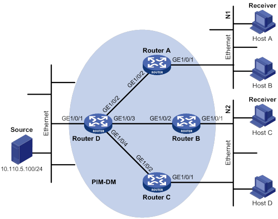
Table 8 Interface and IP address assignment
|
Device |
Interface |
IP address |
Device |
Interface |
IP address |
|
Router A |
10.110.1.1/24 |
Router C |
192.168.3.1/24 |
||
|
Router A |
192.168.1.1/24 |
Router D |
10.110.5.1/24 |
||
|
Router B |
10.110.2.1/24 |
Router D |
192.168.1.2/24 |
||
|
Router B |
192.168.2.1/24 |
Router D |
192.168.2.2/24 |
||
|
Router C |
10.110.2.2/24 |
Router D |
192.168.3.2/24 |
Configuration procedure
1. Assign an IP address and subnet mask for each interface, as shown in Figure 44. (Details not shown.)
2. Configure OSPF on the routers in the PIM-DM domain. (Details not shown.)
3. Enable IP multicast routing, IGMP, and PIM-DM:
# On Router A, enable IP multicast routing.
<RouterA> system-view
[RouterA] multicast routing
[RouterA-mrib] quit
# Enable IGMP on the receiver-side interface (GigabitEthernet 1/0/1).
[RouterA] interface gigabitethernet 1/0/1
[RouterA-GigabitEthernet1/0/1] igmp enable
[RouterA-GigabitEthernet1/0/1] quit
# Enable PIM-DM on GigabitEthernet 1/0/2.
[RouterA] interface gigabitethernet 1/0/2
[RouterA-GigabitEthernet1/0/2] pim dm
[RouterA-GigabitEthernet1/0/2] quit
# Enable IP multicast routing, IGMP, and PIM-DM on Router B and Router C in the same way Router A is configured. (Details not shown.)
# On Router D, enable IP multicast routing, and enable PIM-DM on each interface.
<RouterD> system-view
[RouterD] multicast routing
[RouterD-mrib] quit
[RouterD] interface gigabitethernet 1/0/1
[RouterD-GigabitEthernet1/0/1] pim dm
[RouterD-GigabitEthernet1/0/1] quit
[RouterD] interface gigabitethernet 1/0/2
[RouterD-GigabitEthernet1/0/2] pim dm
[RouterD-GigabitEthernet1/0/2] quit
[RouterD] interface gigabitethernet 1/0/3
[RouterD-GigabitEthernet1/0/3] pim dm
[RouterD-GigabitEthernet1/0/3] quit
[RouterD] interface gigabitethernet 1/0/4
[RouterD-GigabitEthernet1/0/4] pim dm
[RouterD-GigabitEthernet1/0/4] quit
Verifying the configuration
# Display PIM information on Router D.
[RouterD] display pim interface
Interface NbrCnt HelloInt DR-Pri DR-Address
GE1/0/1 0 30 1 10.110.5.1 (local)
GE1/0/2 1 30 1 192.168.1.2 (local)
GE1/0/3 1 30 1 192.168.2.2 (local)
GE1/0/4 1 30 1 192.168.3.2 (local)
# Display the PIM neighboring relationships on Router D.
[RouterD] display pim neighbor
Total Number of Neighbors = 3
Neighbor Interface Uptime Expires Dr-Priority Mode
192.168.1.1 GE1/0/2 00:02:22 00:01:27 1
192.168.2.1 GE1/0/3 00:00:22 00:01:29 1
192.168.3.1 GE1/0/4 00:00:23 00:01:31 1
# Send an IGMP report from Host A to join multicast group 225.1.1.1. (Details not shown.)
# Send multicast data from multicast source 10.110.5.100/24 to multicast group 225.1.1.1. (Details not shown.)
# Display the PIM routing table on Router A.
[RouterA] display pim routing-table
Total 1 (*, G) entry; 1 (S, G) entry
(*, 225.1.1.1)
Protocol: pim-dm, Flag: WC
UpTime: 00:04:25
Upstream interface: NULL
Upstream neighbor: NULL
RPF prime neighbor: NULL
Downstream interface(s) information:
Total number of downstreams: 1
1: GigabitEthernet1/0/1
Protocol: igmp, UpTime: 00:04:25, Expires: -
(10.110.5.100, 225.1.1.1)
Protocol: pim-dm, Flag: ACT
UpTime: 00:06:14
Upstream interface: GigabitEthernet1/0/2
Upstream neighbor: 192.168.1.2
RPF prime neighbor: 192.168.1.2
Downstream interface(s) information:
Total number of downstreams: 1
1: GigabitEthernet1/0/1
Protocol: pim-dm, UpTime: 00:04:25, Expires: -
# Display the PIM routing table on Router D.
[RouterD] display pim routing-table
Total 0 (*, G) entry; 1 (S, G) entry
(10.110.5.100, 225.1.1.1)
Protocol: pim-dm, Flag: LOC ACT
UpTime: 00:03:27
Upstream interface: GigabitEthernet1/0/1
Upstream neighbor: NULL
RPF prime neighbor: NULL
Downstream interface(s) information:
Total number of downstreams: 1
1: GigabitEthernet1/0/2
Protocol: pim-dm, UpTime: 00:03:27, Expires: -
The output shows the following information:
· Routers on the SPT path (Router A and Router D) have the correct (S, G) entries.
· Router A has the correct (*, G) entry.
PIM-SM non-scoped zone configuration example
Network requirements
As shown in Figure 45:
· OSPF runs on the network.
· VOD streams are sent to receiver hosts in multicast. The receivers of different subnets form stub networks, and a minimum of one receiver host exist on each stub network.
· The entire PIM-SM domain contains only one BSR.
· Host A and Host C are multicast receivers in the stub networks N1 and N2.
· Specify GigabitEthernet 1/0/3 on Router E as a C-BSR and a C-RP. The C-RP is designated to the multicast group range of 225.1.1.0/24. Specify GigabitEthernet 1/0/2 of Router D as the static RP on all the routers to back up the dynamic RP.
· IGMPv2 runs between Router A and N1, and between Router B, Router C, and N2.

Table 9 Interface and IP address assignment
|
Device |
Interface |
IP address |
Device |
Interface |
IP address |
|
Router A |
Router D |
||||
|
Router A |
Router D |
||||
|
Router B |
Router E |
||||
|
Router E |
|||||
|
Router C |
Router E |
Configuration procedure
1. Assign an IP address and subnet mask to each interface, as shown in Figure 45. (Details not shown.)
2. Configure OSPF on all routers in the PIM-SM domain. (Details not shown.)
3. Enable IP multicast routing, IGMP and PIM-SM:
# On Router A, enable IP multicast routing.
<RouterA> system-view
[RouterA] multicast routing
[RouterA-mrib] quit
# Enable IGMP on the receiver-side interface (GigabitEthernet 1/0/1).
[RouterA] interface gigabitethernet 1/0/1
[RouterA-GigabitEthernet1/0/1] igmp enable
[RouterA-GigabitEthernet1/0/1] quit
# Enable PIM-SM on the other interfaces.
[RouterA] interface gigabitethernet 1/0/2
[RouterA-GigabitEthernet1/0/2] pim sm
[RouterA-GigabitEthernet1/0/2] quit
[RouterA] interface gigabitethernet 1/0/3
[RouterA-GigabitEthernet1/0/3] pim sm
[RouterA-GigabitEthernet1/0/3] quit
# Enable IP multicast routing, IGMP and PIM-SM on Router B and Router C in the same way Router A is configured. (Details not shown.)
# Enable IP multicast routing and PIM-SM on Router D and Router E in the same way Router A is configured. (Details not shown.)
4. Configure C-BSRs, C-RPs, and the static RP:
# On Router E, configure the service scope of RP advertisements.
<RouterE> system-view
[RouterE] acl basic 2005
[RouterE-acl-ipv4-basic-2005] rule permit source 225.1.1.0 0.0.0.255
[RouterE-acl-ipv4-basic-2005] quit
# Configure GigabitEthernet 1/0/3 as a C-BSR and a C-RP, and configure GigabitEthernet 1/0/2 of Router D as the static RP.
[RouterE] pim
[RouterE-pim] c-bsr 192.168.9.2
[RouterE-pim] c-rp 192.168.9.2 group-policy 2005
[RouterE-pim] static-rp 192.168.1.2
[RouterE-pim] quit
# On Router A, configure GigabitEthernet 1/0/2 of Router D as the static RP.
[RouterA] pim
[RouterA-pim] static-rp 192.168.1.2
[RouterA-pim] quit
# Configure the static RP on Router B, Router C, and Router D in the same way Router A is configured. (Details not shown.)
Verifying the configuration
# Display PIM information on Router A.
[RouterA] display pim interface
Interface NbrCnt HelloInt DR-Pri DR-Address
GE1/0/2 1 30 1 192.168.1.2
GE1/0/3 1 30 1 192.168.9.2
# Display BSR information on Router A.
[RouterA] display pim bsr-info
Scope: non-scoped
State: Accept Preferred
Bootstrap timer: 00:01:44
Elected BSR address: 192.168.9.2
Priority: 64
Hash mask length: 30
Uptime: 00:11:18
# Display BSR information on Router E.
[RouterE] display pim bsr-info
Scope: non-scoped
State: Elected
Bootstrap timer: 00:01:44
Elected BSR address: 192.168.9.2
Priority: 64
Hash mask length: 30
Uptime: 00:11:18
Candidate BSR address: 192.168.9.2
Priority: 64
Hash mask length: 30
# Display RP information on Router A.
[RouterA] display pim rp-info
BSR RP information:
Scope: non-scoped
Group/MaskLen: 225.1.1.0/24
RP address Priority HoldTime Uptime Expires
192.168.9.2 192 180 00:51:45 00:02:22
Static RP information:
RP address ACL Mode Preferred
192.168.1.2 ---- pim-sm No
PIM-SM admin-scoped zone configuration example
Network requirements
As shown in Figure 46:
· OSPF runs on the network.
· VOD streams are sent to receiver hosts in multicast. The entire PIM-SM domain is divided into admin-scoped zone 1, admin-scoped zone 2, and the global-scoped zone. Router B, Router C, and Router D are ZBRs of the three zones, respectively.
· Source 1 and Source 2 send different multicast data to multicast group 239.1.1.1. Host A receives the multicast data only from Source 1, and Host B receives the multicast data only from Source 2. Source 3 sends multicast data to multicast group 224.1.1.1. Host C is a multicast receiver for multicast group 224.1.1.1.
· GigabitEthernet 1/0/2 of Router B acts as a C-BSR and a C-RP for admin-scoped zone 1, and GigabitEthernet 1/0/1 of Router D acts as a C-BSR and a C-RP for admin-scoped zone 2. Both of the two interfaces are designated to multicast group range 239.0.0.0/8. GigabitEthernet 1/0/1 of Router F acts as a C-BSR and a C-RP for the global-scoped zone, and is designated to all the multicast groups that are not in the range 239.0.0.0/8.
· IGMPv2 runs between Router A, Router E, Router I, and the receivers that directly connect to them, respectively.
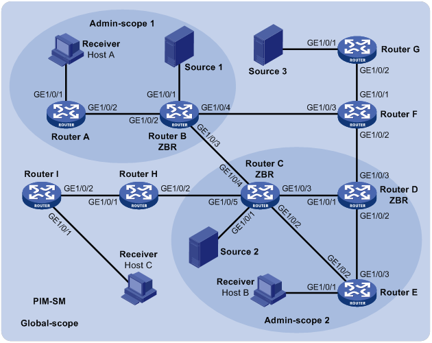
Table 10 Interface and IP address assignment
|
Device |
Interface |
IP address |
Device |
Interface |
IP address |
|
Router A |
GE1/0/1 |
192.168.1.1/24 |
|||
|
Router A |
GE1/0/2 |
10.110.1.1/24 |
Router D |
||
|
Router B |
GE1/0/1 |
192.168.2.1/24 |
Router D |
||
|
Router B |
GE1/0/2 |
10.110.1.2/24 |
|||
|
Router B |
GE1/0/3 |
10.110.2.1/24 |
Router E |
||
|
Router B |
GE1/0/4 |
10.110.3.1/24 |
Router E |
||
|
Router C |
GE1/0/1 |
192.168.3.1/24 |
|||
|
Router C |
GE1/0/2 |
10.110.4.1/24 |
Router F |
||
|
Router C |
GE1/0/3 |
10.110.5.1/24 |
Router F |
||
|
Router C |
GE1/0/4 |
10.110.2.2/24 |
|||
|
Router C |
GE1/0/5 |
10.110.6.1/24 |
Router G |
||
|
Router H |
GE1/0/1 |
10.110.5.2/24 |
— |
||
|
Router H |
GE1/0/2 |
10.110.7.1/24 |
— |
||
|
Router I |
GE1/0/1 |
— |
|||
|
Router I |
GE1/0/2 |
|
|
|
Configuration procedure
1. Assign an IP address and subnet mask to each interface, as shown in Figure 46. (Details not shown.)
2. Configure OSPF on all routers in the PIM-SM domain. (Details not shown.)
3. Enable IP multicast routing, IGMP, and PIM-SM:
# On Router A, enable IP multicast routing.
<RouterA> system-view
[RouterA] multicast routing
[RouterA-mrib] quit
# Enable IGMP on the receiver-side interface (GigabitEthernet 1/0/1).
[RouterA] interface gigabitethernet 1/0/1
[RouterA-GigabitEthernet1/0/1] igmp enable
[RouterA-GigabitEthernet1/0/1] quit
# Enable PIM-SM on GigabitEthernet 1/0/2.
[RouterA] interface gigabitethernet 1/0/2
[RouterA-GigabitEthernet1/0/2] pim sm
[RouterA-GigabitEthernet1/0/2] quit
# Enable IP multicast routing, IGMP and PIM-SM on Router E and Router I in the same way Router A is configured. (Details not shown.)
# On Router B, enable IP multicast routing, and enable PIM-SM on each interface.
<RouterB> system-view
[RouterB] multicast routing
[RouterB-mrib] quit
[RouterB] interface gigabitethernet 1/0/1
[RouterB-GigabitEthernet1/0/1] pim sm
[RouterB-GigabitEthernet1/0/1] quit
[RouterB] interface gigabitethernet 1/0/2
[RouterB-GigabitEthernet1/0/2] pim sm
[RouterB-GigabitEthernet1/0/2] quit
[RouterB] interface gigabitethernet 1/0/3
[RouterB-GigabitEthernet1/0/3] pim sm
[RouterB-GigabitEthernet1/0/3] quit
[RouterB] interface gigabitethernet 1/0/4
[RouterB-GigabitEthernet1/0/4] pim sm
[RouterB-GigabitEthernet1/0/4] quit
# Enable IP multicast routing and PIM-SM on Router C, Router D, Router F, Router G, and Router H in the same way Router B is configured. (Details not shown.)
4. Configure admin-scoped zone boundaries:
# On Router B, configure GigabitEthernet 1/0/3 and GigabitEthernet 1/0/4 as the boundaries of admin-scoped zone 1.
[RouterB] interface gigabitethernet 1/0/3
[RouterB-GigabitEthernet1/0/3] multicast boundary 239.0.0.0 8
[RouterB-GigabitEthernet1/0/3] quit
[RouterB] interface gigabitethernet 1/0/4
[RouterB-GigabitEthernet1/0/4] multicast boundary 239.0.0.0 8
[RouterB-GigabitEthernet1/0/4] quit
# On Router C, configure GigabitEthernet 1/0/4 and GigabitEthernet 1/0/5 as the boundaries of admin-scoped zone 2.
<RouterC> system-view
[RouterC] interface gigabitethernet 1/0/4
[RouterC-GigabitEthernet1/0/4] multicast boundary 239.0.0.0 8
[RouterC-GigabitEthernet1/0/4] quit
[RouterC] interface gigabitethernet 1/0/5
[RouterC-GigabitEthernet1/0/5] multicast boundary 239.0.0.0 8
[RouterC-GigabitEthernet1/0/5] quit
# On Router D, configure GigabitEthernet 1/0/3 as the boundary of admin-scoped zone 2.
<RouterD> system-view
[RouterD] interface gigabitethernet 1/0/3
[RouterD-GigabitEthernet1/0/3] multicast boundary 239.0.0.0 8
[RouterD-GigabitEthernet1/0/3] quit
5. Configure C-BSRs and C-RPs:
# On Router B, configure the service scope of RP advertisements.
[RouterB] acl basic 2001
[RouterB-acl-ipv4-basic-2001] rule permit source 239.0.0.0 0.255.255.255
[RouterB-acl-ipv4-basic-2001] quit
# Configure GigabitEthernet 1/0/2 as a C-BSR and a C-RP for admin-scoped zone 1.
[RouterB] pim
[RouterB-pim] c-bsr 10.110.1.2 scope 239.0.0.0 8
[RouterB-pim] c-rp 10.110.1.2 group-policy 2001
[RouterB-pim] quit
# On Router D, configure the service scope of RP advertisements.
[RouterD] acl basic 2001
[RouterD-acl-ipv4-basic-2001] rule permit source 239.0.0.0 0.255.255.255
[RouterD-acl-ipv4-basic-2001] quit
# Configure GigabitEthernet 1/0/1 as a C-BSR and a C-RP for admin-scoped zone 2.
[RouterD] pim
[RouterD-pim] c-bsr 10.110.5.2 scope 239.0.0.0 8
[RouterD-pim] c-rp 10.110.5.2 group-policy 2001
[RouterD-pim] quit
# On Router F, configure GigabitEthernet 1/0/1 as a C-BSR and a C-RP for the global-scoped zone.
<RouterF> system-view
[RouterF] pim
[RouterF-pim] c-bsr 10.110.9.1
[RouterF-pim] c-rp 10.110.9.1
[RouterF-pim] quit
Verifying the configuration
# Display BSR information on Router B.
[RouterB] display pim bsr-info
Scope: non-scoped
State: Accept Preferred
Bootstrap timer: 00:01:44
Elected BSR address: 10.110.9.1
Priority: 64
Hash mask length: 30
Uptime: 00:01:45
Scope: 239.0.0.0/8
State: Elected
Bootstrap timer: 00:00:06
Elected BSR address: 10.110.1.2
Priority: 64
Hash mask length: 30
Uptime: 00:04:54
Candidate BSR address: 10.110.1.2
Priority: 64
Hash mask length: 30
# Display BSR information on Router D.
[RouterD] display pim bsr-info
Scope: non-scoped
State: Accept Preferred
Bootstrap timer: 00:01:44
Elected BSR address: 10.110.9.1
Priority: 64
Hash mask length: 30
Uptime: 00:01:45
Scope: 239.0.0.0/8
State: Elected
Bootstrap timer: 00:01:12
Elected BSR address: 10.110.5.2
Priority: 64
Hash mask length: 30
Uptime: 00:03:48
Candidate BSR address: 10.110.5.2
Priority: 64
Hash mask length: 30
# Display BSR information on Router F.
[RouterF] display pim bsr-info
Scope: non-scoped
State: Elected
Bootstrap timer: 00:00:49
Elected BSR address: 10.110.9.1
Priority: 64
Hash mask length: 30
Uptime: 00:11:11
Candidate BSR address: 10.110.9.1
Priority: 64
Hash mask length: 30
# Display RP information on Router B.
[RouterB] display pim rp-info
BSR RP information:
Scope: non-scoped
Group/MaskLen: 224.0.0.0/4
RP address Priority HoldTime Uptime Expires
10.110.9.1 192 180 00:03:39 00:01:51
Scope: 239.0.0.0/8
Group/MaskLen: 239.0.0.0/8
RP address Priority HoldTime Uptime Expires
10.110.1.2 (local) 192 180 00:07:44 00:01:51
# Display RP information on Router D.
[RouterD] display pim rp-info
BSR RP information:
Scope: non-scoped
Group/MaskLen: 224.0.0.0/4
RP address Priority HoldTime Uptime Expires
10.110.9.1 192 180 00:03:42 00:01:48
Scope: 239.0.0.0/8
Group/MaskLen: 239.0.0.0/8
RP address Priority HoldTime Uptime Expires
10.110.5.2 (local) 192 180 00:06:54 00:02:41
# Display RP information on Router F.
[RouterF] display pim rp-info
BSR RP information:
Scope: non-scoped
Group/MaskLen: 224.0.0.0/4
RP address Priority HoldTime Uptime Expires
10.110.9.1 (local) 192 180 00:00:32 00:01:58
BIDIR-PIM configuration example
Network requirements
As shown in Figure 47:
· OSPF runs on the network.
· VOD streams are sent to receiver hosts in multicast.
· Source 1 and Source 2 send multicast data to multicast group 225.1.1.1.
· Host A and Host B are receivers of this multicast group.
· GigabitEthernet 1/0/1 of Router C acts as the C-BSR. Loopback 0 of Router C acts as the C-RP.
· IGMPv2 runs between Router B and Host A, and between Router D and Host B.

Table 11 Interface and IP address assignment
|
Device |
Interface |
IP address |
Device |
Interface |
IP address |
|
Router A |
GE1/0/1 |
192.168.1.1/24 |
Router D |
GE1/0/1 |
192.168.3.1/24 |
|
Router A |
GE1/0/2 |
10.110.1.1/24 |
Router D |
GE1/0/2 |
192.168.4.1/24 |
|
Router B |
GE1/0/1 |
192.168.2.1/24 |
Router D |
GE1/0/3 |
10.110.3.2/24 |
|
Router B |
GE1/0/2 |
10.110.1.2/24 |
Source 1 |
— |
192.168.1.100/24 |
|
Router B |
GE1/0/3 |
10.110.2.1/24 |
Source 2 |
— |
192.168.4.100/24 |
|
Router C |
GE1/0/1 |
10.110.2.2/24 |
Receiver 1 |
— |
192.168.2.100/24 |
|
Router C |
GE1/0/2 |
10.110.3.1/24 |
Receiver 2 |
— |
192.168.3.100/24 |
|
Router C |
Loop0 |
1.1.1.1/32 |
|
|
|
Configuration procedure
1. Assign an IP address and subnet mask to each interface, as shown in Figure 47. (Details not shown.)
2. Configure OSPF on the routers in the BIDIR-PIM domain. (Details not shown.)
3. Enable IP multicast routing, PIM-SM, BIDIR-PIM, and IGMP:
# On Router A, enable IP multicast routing, enable PIM-SM on each interface, and enable BIDIR-PIM.
<RouterA> system-view
[RouterA] multicast routing
[RouterA-mrib] quit
[RouterA] interface gigabitethernet 1/0/1
[RouterA-GigabitEthernet1/0/1] pim sm
[RouterA-GigabitEthernet1/0/1] quit
[RouterA] interface gigabitethernet 1/0/2
[RouterA-GigabitEthernet1/0/2] pim sm
[RouterA-GigabitEthernet1/0/2] quit
[RouterA] pim
[RouterA-pim] bidir-pim enable
[RouterA-pim] quit
# On Router B, enable IP multicast routing.
<RouterB> system-view
[RouterB] multicast routing
[RouterB-mrib] quit
# Enable IGMP on the receiver-side interface (GigabitEthernet 1/0/1).
[RouterB] interface gigabitethernet 1/0/1
[RouterB-GigabitEthernet1/0/1] igmp enable
[RouterB-GigabitEthernet1/0/1] quit
# Enable PIM-SM on the other interfaces.
[RouterB] interface gigabitethernet 1/0/2
[RouterB-GigabitEthernet1/0/2] pim sm
[RouterB-GigabitEthernet1/0/2] quit
[RouterB] interface gigabitethernet 1/0/3
[RouterB-GigabitEthernet1/0/3] pim sm
[RouterB-GigabitEthernet1/0/3] quit
# Enable BIDIR-PIM.
[RouterB] pim
[RouterB-pim] bidir-pim enable
[RouterB-pim] quit
# On Router C, enable IP multicast routing, enable PIM-SM on each interface, and enable BIDIR-PIM.
<RouterC> system-view
[RouterC] multicast routing
[RouterC-mrib] quit
[RouterC] interface gigabitethernet 1/0/1
[RouterC-GigabitEthernet1/0/1] pim sm
[RouterC-GigabitEthernet1/0/1] quit
[RouterC] interface gigabitethernet 1/0/2
[RouterC-GigabitEthernet1/0/2] pim sm
[RouterC-GigabitEthernet1/0/2] quit
[RouterC] interface loopback 0
[RouterC-LoopBack0] pim sm
[RouterC-LoopBack0] quit
[RouterC] pim
[RouterC-pim] bidir-pim enable
# On Router D, enable IP multicast routing.
<RouterD> system-view
[RouterD] multicast routing
[RouterD-mrib] quit
# Enable IGMP on the receiver-side interface (GigabitEthernet 1/0/1).
[RouterD] interface gigabitethernet 1/0/1
[RouterD-GigabitEthernet1/0/1] igmp enable
[RouterD-GigabitEthernet1/0/1] quit
# Enable PIM-SM on other interfaces.
[RouterD] interface gigabitethernet 1/0/2
[RouterD-GigabitEthernet1/0/2] pim sm
[RouterD-GigabitEthernet1/0/2] quit
[RouterD] interface gigabitethernet 1/0/3
[RouterD-GigabitEthernet1/0/3] pim sm
[RouterD-GigabitEthernet1/0/3] quit
# Enable BIDIR-PIM.
[RouterD] pim
[RouterD-pim] bidir-pim enable
[RouterD-pim] quit
4. On Router C, configure GigabitEthernet 1/0/1 as the C-BSR, and Loopback 0 as the C-RP for the entire BIDIR-PIM domain.
[RouterC-pim] c-bsr 10.110.2.2
[RouterC-pim] c-rp 1.1.1.1 bidir
[RouterC-pim] quit
Verifying the configuration
1. Display the DF information of BIDIR-PIM:
# Display the DF information of BIDIR-PIM on Router A.
[RouterA] display pim df-info
RP address: 1.1.1.1
Interface: GigabitEthernet1/0/1
State : Win DF preference: 100
DF metric : 2 DF uptime : 00:06:59
DF address: 192.168.1.1 (local)
Interface: GigabitEthernet1/0/2
State : Lose DF preference: 100
DF metric : 1 DF uptime : 00:06:59
DF address: 10.110.1.2
# Display the DF information of BIDIR-PIM on Router B.
[RouterB] display pim df-info
RP address: 1.1.1.1
Interface: GigabitEthernet1/0/2
State : Win DF preference: 100
DF metric : 1 DF uptime : 00:06:59
DF address: 10.110.1.2 (local)
Interface: GigabitEthernet1/0/3
State : Lose DF preference: 0
DF metric : 0 DF uptime : 00:06:59
DF address: 10.110.2.2
# Display the DF information of BIDIR-PIM on Router C.
[RouterC] display pim df-info
RP address: 1.1.1.1
Interface: Loop0
State : - DF preference: -
DF metric : - DF uptime : -
DF address: -
RP address: 1.1.1.1
Interface: GigabitEthernet1/0/1
State : Win DF preference: 0
DF metric : 0 DF uptime : 00:06:59
DF address: 10.110.2.2 (local)
Interface: GigabitEthernet1/0/2
State : Win DF preference: 0
DF metric : 0 DF uptime : 00:06:59
DF address: 10.110.3.1
# Display the DF information of BIDIR-PIM on Router D.
[RouterD] display pim df-info
RP address: 1.1.1.1
Interface: GigabitEthernet1/0/2
State : Win DF preference: 100
DF metric : 1 DF uptime : 00:06:59
DF address: 192.168.4.1 (local)
Interface: GigabitEthernet1/0/3
State : Lose DF preference: 0
DF metric : 0 DF uptime : 00:06:59
DF address: 10.110.3.1
2. Display information about the DF for multicast forwarding:
# Display information about the DF for multicast forwarding on Router A.
[RouterA] display multicast forwarding df-info
Total 1 RPs, 1 matched
00001. RP address: 1.1.1.1
Flags: 0x0
Uptime: 00:08:32
RPF interface: GigabitEthernet1/0/2
List of 1 DF interfaces:
1: GigabitEthernet1/0/1
# Display information about the DF for multicast forwarding on Router B.
[RouterB] display multicast forwarding df-info
Total 1 RPs, 1 matched
00001. RP address: 1.1.1.1
Flags: 0x0
Uptime: 00:06:24
RPF interface: GigabitEthernet1/0/3
List of 1 DF interfaces:
1: GigabitEthernet1/0/2
# Display information about the DF for multicast forwarding on Router C.
[RouterC] display multicast forwarding df-info
Total 1 RPs, 1 matched
00001. RP address: 1.1.1.1
Flags: 0x0
Uptime: 00:07:21
RPF interface: LoopBack0
List of 2 DF interfaces:
1: GigabitEthernet1/0/1
2: GigabitEthernet1/0/2
# Display information about the DF for multicast forwarding on Router D.
[RouterD] display multicast forwarding df-info
Total 1 RPs, 1 matched
00001. RP address: 1.1.1.1
Flags: 0x0
Uptime: 00:05:12
RPF interface: GigabitEthernet1/0/3
List of 1 DF interfaces:
1: GigabitEthernet1/0/2
PIM-SSM configuration example
Network requirements
As shown in Figure 48:
· OSPF runs on the network.
· The receivers receive VOD information through multicast. The receiver groups of different organizations form stub networks, and one or more receiver hosts exist in each stub network. The entire PIM domain operates in the SSM mode.
· Host A and Host C are multicast receivers on two stub networks.
· The SSM group range is 232.1.1.0/24.
· IGMPv3 runs between Router A and N1, and between Router B, Router C, and N2.
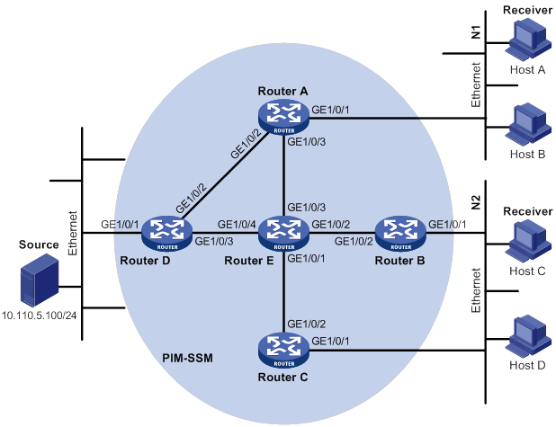
Table 12 Interface and IP address assignment
|
Device |
Interface |
IP address |
Device |
Interface |
IP address |
|
Router A |
GE1/0/1 |
10.110.1.1/24 |
Router D |
GE1/0/1 |
10.110.5.1/24 |
|
Router A |
GE1/0/2 |
192.168.1.1/24 |
Router D |
GE1/0/2 |
192.168.1.2/24 |
|
Router A |
GE1/0/3 |
192.168.9.1/24 |
Router D |
GE1/0/3 |
192.168.4.2/24 |
|
Router B |
GE1/0/1 |
10.110.2.1/24 |
Router E |
GE1/0/1 |
192.168.3.2/24 |
|
Router B |
GE1/0/2 |
192.168.2.1/24 |
Router E |
GE1/0/2 |
192.168.2.2/24 |
|
Router C |
GE1/0/1 |
10.110.2.2/24 |
Router E |
GE1/0/3 |
192.168.9.2/24 |
|
Router C |
GE1/0/2 |
192.168.3.1/24 |
Router E |
GE1/0/4 |
192.168.4.1/24 |
Configuration procedure
1. Assign an IP address and subnet mask to each interface, as shown in Figure 48. (Details not shown.)
2. Configure OSPF on the routers in the PIM-SSM domain. (Details not shown.)
3. Enable IP multicast routing, IGMP and PIM-SM:
# On Router A, enable IP multicast routing.
<RouterA> system-view
[RouterA] multicast routing
[RouterA-mrib] quit
# Enable IGMPv3 on GigabitEthernet 1/0/1 (the interface that connects to the stub network).
[RouterA] interface gigabitethernet 1/0/1
[RouterA-GigabitEthernet1/0/1] igmp enable
[RouterA-GigabitEthernet1/0/1] igmp version 3
[RouterA-GigabitEthernet1/0/1] quit
# Enable PIM-SM on the other interfaces.
[RouterA] interface gigabitethernet 1/0/2
[RouterA-GigabitEthernet1/0/2] pim sm
[RouterA-GigabitEthernet1/0/2] quit
[RouterA] interface gigabitethernet 1/0/3
[RouterA-GigabitEthernet1/0/3] pim sm
[RouterA-GigabitEthernet1/0/3] quit
# Enable IP multicast routing, IGMP, and PIM-SM on Router B and Router C in the same way Router A is configured. (Details not shown.)
# Enable IP multicast routing and PIM-SM on Router D and Router E in the same way Router A is configured. (Details not shown.)
4. Configure the SSM group range:
# On Router A, specify 232.1.1.0/24 as the SSM group range.
[RouterA] acl basic 2000
[RouterA-acl-ipv4-basic-2000] rule permit source 232.1.1.0 0.0.0.255
[RouterA-acl-ipv4-basic-2000] quit
[RouterA] pim
[RouterA-pim] ssm-policy 2000
[RouterA-pim] quit
# Configure the SSM group range on Router B, Router C, Router D, and Router E in the same way Router A is configured (Details not shown.)
Verifying the configuration
# Display PIM information on Router A.
[RouterA] display pim interface
Interface NbrCnt HelloInt DR-Pri DR-Address
GE1/0/2 1 30 1 192.168.1.2
GE1/0/3 1 30 1 192.168.9.2
# Send an IGMPv3 report from Host A to join the multicast source and group (10.110.5.100/24, 232.1.1.1). (Details not shown.)
# Display the PIM routing table on Router A.
[RouterA] display pim routing-table
Total 0 (*, G) entry; 1 (S, G) entry
(10.110.5.100, 232.1.1.1)
Protocol: pim-ssm, Flag:
UpTime: 00:13:25
Upstream interface: GigabitEthernet1/0/2
Upstream neighbor: 192.168.1.2
RPF prime neighbor: 192.168.1.2
Downstream interface(s) information:
Total number of downstreams: 1
1: GigabitEthernet1/0/1
Protocol: igmp, UpTime: 00:13:25, Expires: 00:03:25
# Display PIM routing entries on Router D.
[RouterD] display pim routing-table
Total 0 (*, G) entry; 1 (S, G) entry
(10.110.5.100, 232.1.1.1)
Protocol: pim-ssm, Flag: LOC
UpTime: 00:12:05
Upstream interface: GigabitEthernet1/0/1
Upstream neighbor: NULL
RPF prime neighbor: NULL
Downstream interface(s) information:
Total number of downstreams: 1
1: GigabitEthernet1/0/2
Protocol: pim-ssm, UpTime: 00:12:05, Expires: 00:03:25
The output shows that routers on the SPT path (Router A and Router D) have generated the correct (S, G) entries.
Troubleshooting PIM
A multicast distribution tree cannot be correctly built
Symptom
No multicast forwarding entries are established on the routers (including routers directly connected with multicast sources or receivers) in a PIM network. This means that a multicast distribution tree cannot be correctly built.
Solution
To resolve the problem:
1. Use display ip routing-table to verify that a unicast route to the multicast source or the RP is available.
2. Use display pim interface to verify PIM information on each interface, especially on the RPF interface. If PIM is not enabled on the interfaces, use pim dm or pim sm to enable PIM-DM or PIM-SM for the interfaces.
3. Use display pim neighbor to verify that the RPF neighbor is a PIM neighbor.
4. Verify that PIM and IGMP are enabled on the interfaces that directly connect to the multicast sources or the receivers.
5. Use display pim interface verbose to verify that the same PIM mode is enabled on the RPF interface on a router and the connected interface of the router's RPF neighbor.
6. Use display current-configuration to verify that the same PIM mode is enabled on all routers. For PIM-SM, verify that the BSR and C-RPs are correctly configured.
7. If the problem persists, contact H3C Support.
Multicast data is abnormally terminated on an intermediate router
Symptom
An intermediate router can receive multicast data successfully, but the data cannot reach the last-hop router. An interface on the intermediate router receives multicast data but does not create an (S, G) entry in the PIM routing table.
Solution
To resolve the problem:
1. Use display current-configuration to verify the multicast forwarding boundary settings. Use multicast boundary to change the multicast forwarding boundary settings to make the multicast packet able to cross the boundary.
2. Use display current-configuration to verify the multicast source policy. Change the ACL rule defined in the source-policy command so that the source/group address of the multicast data can pass ACL filtering.
3. If the problem persists, contact H3C Support.
An RP cannot join an SPT in PIM-SM
Symptom
An RPT cannot be correctly built, or an RP cannot join the SPT toward the multicast source.
Solution
To resolve the problem:
1. Use display ip routing-table to verify that a unicast route to the RP is available on each router.
2. Use display pim rp-info to verify that the dynamic RP information is consistent on all routers.
3. Use display pim rp-info to verify that the same static RPs are configured on all routers on the network.
4. If the problem persists, contact H3C Support.
An RPT cannot be built or multicast source registration fails in PIM-SM
Symptom
The C-RPs cannot unicast advertisement messages to the BSR. The BSR does not advertise BSMs containing C-RP information and has no unicast route to any C-RP. An RPT cannot be correctly established, or the source-side DR cannot register the multicast source with the RP.
Solution
To resolve the problem:
1. Use display ip routing-table on each router to view routing table information. Verify that unicast routes to the C-RPs and the BSR are available on each router and that a route is available between each C-RP and the BSR.
2. Use display pim bsr-info to verify that the BSR information exists on each router.
3. Use display pim rp-info to verify that the RP information is correct on each router.
4. Use display pim neighbor to verify that PIM neighboring relationship has been correctly established among the routers.
5. If the problem persists, contact H3C Support.
Configuring MSDP
Overview
Multicast Source Discovery Protocol (MSDP) is an inter-domain multicast solution that addresses the interconnection of PIM-SM domains. It discovers multicast source information in other PIM-SM domains.
In the basic PIM-SM mode, a multicast source registers only with the RP in the local PIM-SM domain, and the multicast source information in each domain is isolated. As a result, both of the following occur:
· The RP obtains the source information only within the local domain.
· A multicast distribution tree is built only within the local domain to deliver multicast data locally.
MSDP enables the RPs of different PIM-SM domains to share their multicast source information. The local RP can then join the SPT rooted at the multicast source across the PIM-SM domains. This allows multicast data to be transmitted among different domains.
With MSDP peer relationships established between appropriate routers on the network, the RPs of different PIM-SM domains are interconnected with one another. These MSDP peers exchange source active (SA) messages, so that the multicast source information is shared among these domains.
MSDP is applicable only if the intra-domain multicast protocol is PIM-SM. MSDP takes effect only for the ASM model.
For more information about the concepts of DR, BSR, C-BSR, RP, C-RP, SPT, and RPT mentioned in this document, see "Configuring PIM."
How MSDP works
MSDP peers
One or more pairs of MSDP peers on the network form an MSDP interconnection map. In the map, the RPs of different PIM-SM domains interconnect in a series. An SA message from an RP is relayed to all other RPs by these MSDP peers.
Figure 49 MSDP peer locations on the network
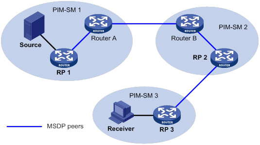
As shown in Figure 49, an MSDP peer can be created on any PIM-SM router. MSDP peers created on PIM-SM routers that assume different roles function differently.
· MSDP peers created on RPs:
? Source-side MSDP peer—MSDP peer closest to the multicast source, such as RP 1. The source-side RP creates and sends SA messages to its remote MSDP peer to notify the MSDP peer of the locally registered multicast source information.
A source-side MSDP peer must be created on the source-side RP. Otherwise, it cannot advertise the multicast source information out of the PIM-SM domain.
? Receiver-side MSDP peer—MSDP peer closest to the receivers, typically the receiver-side RP, such as RP 3. After receiving an SA message, the receiver-side MSDP peer resolves the multicast source information carried in the message. Then, it joins the SPT rooted at the multicast source across the PIM-SM domains. When multicast data from the multicast source arrives, the receiver-side MSDP peer forwards the data to the receivers along the RPT.
? Intermediate MSDP peer—MSDP peer with multiple remote MSDP peers, such as RP 2. An intermediate MSDP peer forwards SA messages received from one remote MSDP peer to other remote MSDP peers. It acts as a relay for forwarding multicast source information.
· MSDP peers created on PIM-SM routers that are not RPs:
Router A and Router B are MSDP peers on multicast routers that are not RPs. Such MSDP peers only forward SA messages.
In a PIM-SM network using the BSR mechanism, the RP is dynamically elected from C-RPs. A PIM-SM network typically has multiple C-RPs to ensure network robustness. Because the RP election result is unpredictable, MSDP peering relationships must be built between all C-RPs to always keep the winning C-RP on the MSDP interconnection map. Losing C-RPs assume the role of common PIM-SM routers on this map.
Inter-domain multicast delivery through MSDP
As shown in Figure 50, an active source (Source) exists in the domain PIM-SM 1, and RP 1 has learned the existence of Source through multicast source registration. RPs in PIM-SM 2 and PIM-SM 3 also seek the location of Source so that multicast traffic from Source can be sent to their receivers. MSDP peering relationships must be established between RP 1 and RP 3 and between RP 3 and RP 2.
Figure 50 Inter-domain multicast delivery through MSDP
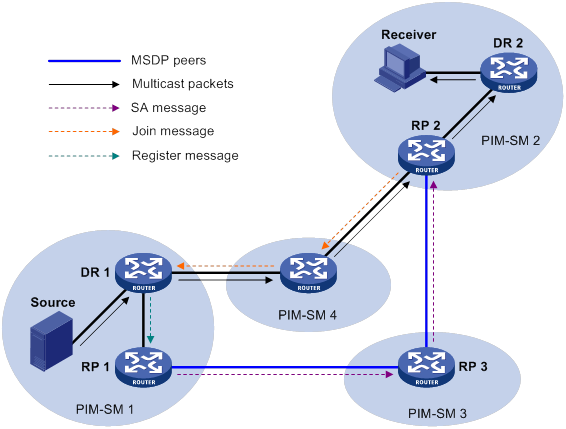
The process of implementing PIM-SM inter-domain multicast delivery by leveraging MSDP peers is as follows:
1. When the multicast source in PIM-SM 1 sends the first multicast packet to multicast group G, DR 1 encapsulates the data within a register message. It sends the register message to RP 1, and RP 1 obtains information about the multicast source.
2. As the source-side RP, RP 1 creates SA messages and periodically sends them to its MSDP peer.
An SA message contains the address of the multicast source (S), the multicast group address (G), and the address of the RP that has created this SA message (RP 1, in this example).
3. On MSDP peers, each SA message undergoes an RPF check and multicast policy-based filtering. Only SA messages that have arrived along the correct path and passed the filtering are received and forwarded. This avoids delivery loops of SA messages. In addition, you can configure MSDP peers into an MSDP mesh group to avoid SA message flooding between MSDP peers.
|
|
NOTE: An MSDP mesh group refers to a group of MSDP peers that establish MSDP peering relationships with each other and share the same group name. |
4. SA messages are forwarded from one MSDP peer to another. Finally, information about the multicast source traverses all PIM-SM domains with MSDP peers (PIM-SM 2 and PIM-SM 3, in this example).
5. After receiving the SA message that RP 1 created, RP 2 in PIM-SM 2 examines whether any receivers for the multicast group exist in the domain.
? If a receiver exists in the domain, the RPT for the multicast group G is maintained between RP 2 and the receivers. RP 2 creates an (S, G) entry and sends an (S, G) join message. The join message travels hop by hop toward the multicast source, and the SPT is established across the PIM-SM domains.
The subsequent multicast data flows to RP 2 along the SPT, and from RP 2 to the receiver-side DR along the RPT. After receiving the multicast data, the receiver-side DR determines whether to initiate an RPT-to-SPT switchover process based on its configuration.
? If no receivers exist in the domain, RP 2 neither creates an (S, G) entry nor sends a join message toward the multicast source.
In inter-domain multicasting using MSDP, once an RP gets information about a multicast source in another PIM-SM domain, it no longer relies on RPs in other PIM-SM domains. The receivers can override the RPs in other domains and directly join the multicast SPT rooted at the source.
Anycast RP through MSDP
PIM-SM requires only one active RP to serve each multicast group. If the active RP fails, the multicast traffic might be interrupted. The Anycast RP mechanism enables redundancy backup between two or more RPs by configuring multiple RPs with the same IP address for one multicast group. A multicast source registers with the closest RP or a receiver joins the closest RP to implement source information synchronization.
Anycast RP has the following benefits:
· Optimal RP path—A multicast source registers with the closest RP to build an optimal SPT. A receiver joins the closest RP to build an optimal RPT.
· Redundancy backup among RPs—When an RP fails, the RP-related sources and receiver-side DRs will register with or join their closest available RPs. This achieves redundancy backup among RPs.
Anycast RP is implemented by using either of the following methods:
· Anycast RP through PIM-SM—In this method, you can configure multiple RPs for one multicast group and add them to an Anycast RP set. For more information about Anycast RP through PIM-SM, see "Configuring PIM."
· Anycast RP through MSDP—In this method, you can configure multiple RPs with the same IP address for one multicast group and configure MSDP peering relationships between the RPs.
As shown in Figure 51, within a PIM-SM domain, a multicast source sends multicast data to multicast group G, and the receiver joins the multicast group.
To implement Anycast RP through MSDP:
a. Assign the same IP address (known as Anycast RP address, typically a private address) to an interface on Router A and Router B.
- An Anycast RP address is usually assigned to a logical interface, such as a loopback interface.
- Make sure the Anycast RP address is a host address (with the subnet mask 255.255.255.255).
b. Configure the interfaces as C-RPs.
c. Establish an MSDP peering relationship between Router A and Router B.
An MSDP peer address must be different from the Anycast RP address.
Figure 51 Anycast RP through MSDP
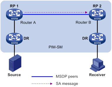
The following describes how Anycast RP through MSDP is implemented:
a. After receiving the multicast data from Source, the source-side DR registers with the closest RP (RP 1 in this example).
b. After receiving the IGMP report message from the receiver, the receiver-side DR sends a join message toward the closest RP (RP 2 in this example). An RPT rooted at this RP is established.
c. The RPs share the registered multicast source information through SA messages. After obtaining the multicast source information, RP 2 sends an (S, G) source-specific join message toward the source to create an SPT.
d. When the multicast data reaches RP 2 along the SPT, the RP forwards the data along the RPT to the receiver. After receiving the multicast data, the receiver-side DR determines whether to initiate an RPT-to-SPT switchover process based on its configuration.
MSDP peer-RPF forwarding
The MSDP peer-RPF check is used for forwarding SA messages on a network that runs MSDP. If the peer-RPF check succeeds, the SA message is accepted and forwarded. Otherwise, the SA message is discarded.
As shown in Figure 52:
· There are five ASs on the network. IGP runs within each AS, and BGP or MBGP runs between these ASs.
· Each AS contains a minimum of one PIM-SM domain, and each PIM-SM domain contains a minimum of one RP.
· MSDP peering relationship has been established among these RPs.
RP 3, RP 4, and RP 5 are in the same MSDP mesh group.
RP 6 is configured as the static RPF peer of RP 7.
Figure 52 MSDP peer-RPF forwarding
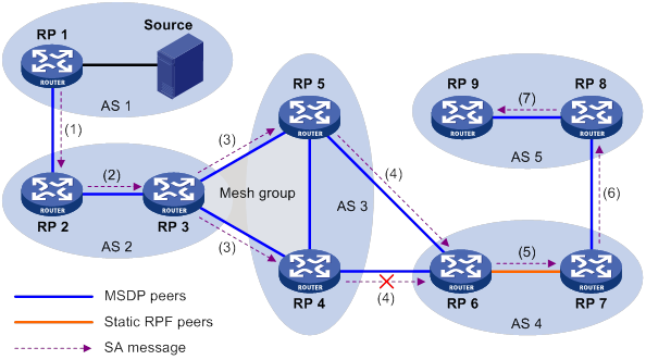
The process of peer-RPF forwarding is as follows:
1. RP 1 creates an SA message and forwards it to its peer RP 2.
2. RP 2 determines that RP 1 is the RP that creates the SA message because the RP address in the SA message is the same as that of RP 1. Then, RP 2 accepts and forwards the SA message.
3. RP 3 accepts and forwards the SA message, because RP 2 and RP 3 reside in the same AS and RP 2 is the next hop of RP 3 to RP 1.
4. RP 4 and RP 5 accept the SA message, because RP 3 is in the same mesh group with them. Then, RP 4 and RP 5 forward the SA message to their peer RP 6 rather than other members of the mesh group.
5. RP 4 and RP 5 reside in the closest AS in the route to RP 1. However, RP 6 accepts and forwards only the SA message from RP 5, because the IP address of RP 5 is higher than that of RP 4.
6. RP 7 accepts and forwards the SA message, because RP 6 is its static RPF peer.
7. RP 8 accepts and forwards the SA message, because RP 7 is the EBGP or MBGP next hop of the peer-RPF route to RP 1.
8. RP 9 accepts the SA message, because RP 8 is the only RP of RP 9.
MSDP support for VPNs
Interfaces on the multicast routers in a VPN can set up MSDP peering relationships with each other. With the SA messages exchanged between MSDP peers, the multi-instance VPN implements the forwarding of multicast data across different PIM-SM domains.
To support MSDP for VPNs, a multicast router that runs MSDP maintains an independent set of MSDP mechanism for each VPN that it supports. These mechanisms include SA message cache, peering connection, timers, sending cache, and cache for exchanging PIM messages.
One VPN is isolated from another, and MSDP and PIM-SM messages can be exchanged only within the same VPN.
Protocols and standards
· RFC 3618, Multicast Source Discovery Protocol (MSDP)
· RFC 3446, Anycast Rendezvous Point (RP) mechanism using Protocol Independent Multicast (PIM) and Multicast Source Discovery Protocol (MSDP)
Feature and hardware compatibility
The following matrix shows the feature and hardware compatibility:
|
Hardware |
MSDP compatibility |
|
MSR810/810-W/810-W-DB/810-LM/810-W-LM/810-10-PoE/810-LM-HK/810-W-LM-HK |
Yes |
|
MSR810-LMS/810-LUS |
No |
|
MSR2600-6-X1/2600-10-X1 |
Yes |
|
MSR 2630 |
Yes |
|
MSR3600-28/3600-51 |
Yes |
|
MSR3600-28-SI/3600-51-SI |
No |
|
MSR3610-X1/3610-X1-DP/3610-X1-DC/3610-X1-DP-DC |
Yes |
|
MSR 3610/3620/3620-DP/3640/3660 |
Yes |
|
MSR5620/5660/5680 |
Yes |
|
Hardware |
MSDP compatibility |
|
MSR810-LM-GL |
Yes |
|
MSR810-W-LM-GL |
Yes |
|
MSR830-6EI-GL |
Yes |
|
MSR830-10EI-GL |
Yes |
|
MSR830-6HI-GL |
Yes |
|
MSR830-10HI-GL |
Yes |
|
MSR2600-6-X1-GL |
Yes |
|
MSR3600-28-SI-GL |
No |
MSDP configuration task list
|
Tasks at a glance |
|
Configuring basic MSDP features: · (Required.) Enabling MSDP · (Required.) Specifying an MSDP peer · (Optional.) Configuring a static RPF peer |
|
Configuring an MSDP peering connection: · (Optional.) Configuring a description for an MSDP peer · (Optional.) Configuring an MSDP mesh group · (Optional.) Controlling MSDP peering connections |
|
Configuring SA message-related parameters: · (Optional.) Enabling multicast data encapsulation in SA messages · (Optional.) Configuring the originating RP of SA messages · (Optional.) Configuring SA request messages · (Optional.) Configuring SA message policies · (Optional.) Configuring the SA cache mechanism |
Configuring basic MSDP features
All the configuration tasks in this section should be performed on RPs in PIM-SM domains, and each of these RPs acts as an MSDP peer.
Configuration prerequisites
Before you configure basic MSDP features, complete the following tasks:
· Configure a unicast routing protocol so that all devices in the domain can interoperate at the network layer.
· Configure PIM-SM to enable intra-domain multicast.
Enabling MSDP
|
Step |
Command |
Remarks |
|
1. Enter system view. |
system-view |
N/A |
|
2. Enable IP multicast routing and enter MRIB view. |
multicast routing [ vpn-instance vpn-instance-name ] |
By default, IP multicast routing is disabled. |
|
3. Return to system view. |
quit |
N/A |
|
4. Enable MSDP and enter MSDP view. |
msdp [ vpn-instance vpn-instance-name ] |
By default, MSDP is disabled. |
Specifying an MSDP peer
An MSDP peering relationship is identified by an address pair (the addresses of the local MSDP peer and the remote MSDP peer). To create an MSDP peering connection, you must perform the following operation on both devices that are a pair of MSDP peers.
If an interface of the router is shared by an MSDP peer and a BGP or MBGP peer at the same time, As a best practice, specify an MSDP peer by using the IP address of the BGP or MBGP peer.
To specify an MSDP peer:
|
Step |
Command |
Remarks |
|
1. Enter system view. |
system-view |
N/A |
|
2. Enter MSDP view. |
msdp [ vpn-instance vpn-instance-name ] |
N/A |
|
3. Specify an MSDP peer. |
peer peer-address connect-interface interface-type interface-number |
By default, no MSDP peers exist. |
Configuring a static RPF peer
This feature prevents SA messages forwarded by the static RPF peer from undertaking the RPF check. This simplifies the RPF check mechanism for SA messages.
You can configure an RP policy for the static RPF peer to filter SA messages based on the used IPv4 prefix list that specifies the RP addresses.
If only one MSDP peer is configured on a router, this MSDP peer is considered to be a static RPF peer.
To configure a static RPF peer:
|
Step |
Command |
Remarks |
|
1. Enter system view. |
system-view |
N/A |
|
2. Enter MSDP view. |
msdp [ vpn-instance vpn-instance-name ] |
N/A |
|
3. Configure a static RPF peer. |
static-rpf-peer peer-address [ rp-policy ip-prefix-name ] |
By default, no static RPF peers exist. |
Configuring an MSDP peering connection
This section describes how to configure an MSDP peering connection.
Configuration prerequisites
Before you configure an MSDP peering connection, complete the following tasks:
· Configure a unicast routing protocol so that all devices in the domain can interoperate at the network layer.
· Configure basic MSDP features.
Configuring a description for an MSDP peer
This feature helps administrators easily distinguish an MSDP peer from other MSDP peers.
To configure a description for an MSDP peer:
|
Step |
Command |
Remarks |
|
1. Enter system view. |
system-view |
N/A |
|
2. Enter MSDP view. |
msdp [ vpn-instance vpn-instance-name ] |
N/A |
|
3. Configure a description for an MSDP peer. |
peer peer-address description text |
By default, no description for an MSDP peer exists. |
Configuring an MSDP mesh group
This feature avoids SA message flooding among MSDP peers within an AS. It also simplifies the RPF check mechanism because you do not need to run BGP or MBGP between these MSDP peers.
When receiving an SA message from outside the mesh group, a member MSDP peer performs the RPF check on the SA message. If the SA message passes the RPF check, the member MSDP peer floods the message to the other members in the mesh group. When receiving an SA message from another member, the MSDP peer neither performs an RPF check on the message nor forwards the message to the other members.
To organize multiple MSDP peers in a mesh group, assign the same mesh group name to these MSDP peers. Before doing this, make sure the routers are interconnected with one another.
To configure an MSDP mesh group:
|
Step |
Command |
Remarks |
|
1. Enter system view. |
system-view |
N/A |
|
2. Enter MSDP view. |
msdp [ vpn-instance vpn-instance-name ] |
N/A |
|
3. Configure an MSDP mesh group. |
peer peer-address mesh-group name |
By default, an MSDP peer does not belong to any mesh group. If you assign an MSDP peer to multiple mesh groups, the most recent configuration takes effect. |
Controlling MSDP peering connections
MSDP peers are interconnected over TCP (port number 639). You can tear down or re-establish MSDP peering connections to control SA message exchange between the MSDP peers. When the connection between two MSDP peers is torn down, SA messages are no longer delivered between them. No attempt is made to re-establish the connection. The configuration information for the peer remains unchanged.
MSDP peers periodically send keepalive messages to each other to keep a session alive. When a session is established, an MSDP peer sends a keepalive message to its peer and starts a keepalive timer and a peer hold timer. When the keepalive timer expires, the MSDP peer sends a new keepalive message. If the MSDP peer receives an MSDP message from its peer before the peer hold timer expires, it resets the peer hold timer. Otherwise, the MSDP peer tears down the session.
A TCP connection is required when one of the following conditions exists:
· A new MSDP peer is created.
· A previously deactivated MSDP peering connection is reactivated.
· A previously failed MSDP peer attempts to resume operation.
You can change the MSDP connection retry interval to adjust the interval between MSDP peering connection attempts.
To enhance MSDP security, enable MD5 authentication for both MSDP peers to establish a TCP connection. If the MD5 authentication fails, the TCP connection cannot be established.
|
|
IMPORTANT: The MSDP peers involved in MD5 authentication must be configured with the same authentication method and key. Otherwise, the authentication fails and the TCP connection cannot be established. |
To control MSDP peering connections:
|
Step |
Command |
Remarks |
|
1. Enter system view. |
system-view |
N/A |
|
2. Enter MSDP view. |
msdp [ vpn-instance vpn-instance-name ] |
N/A |
|
3. Tear down an MSDP peering connection. |
shutdown peer-address |
By default, an MSDP peering connection is active. |
|
4. Set the keepalive timer and peer hold timer for MSDP sessions. |
By default, the keepalive timer and peer hold timer are 60 seconds and 75 seconds, respectively. This command immediately takes effect on an established session. |
|
|
5. Configure the MSDP connection retry interval. |
timer retry interval |
The default setting is 30 seconds. |
|
6. Configure MD5 authentication for both MSDP peers to establish a TCP connection. |
peer peer-address password { cipher | simple } password |
By default, MD5 authentication is not performed before a TCP connection is established. |
Configuring SA message-related parameters
This section describes how to configure SA message-related parameters.
Configuration prerequisites
Before you configure SA message delivery, complete the following tasks:
· Configure a unicast routing protocol so that all devices in the domain can interoperate at the network layer.
· Configure basic MSDP features.
Enabling multicast data encapsulation in SA messages
Some multicast sources send multicast data at an interval longer than the aging time of (S, G) entries. In this case, the source-side DR must encapsulate multicast data packet-by-packet in register messages and send them to the source-side RP. The source-side RP transmits the (S, G) information to the remote RP through SA messages. Then, the remote RP sends join messages to the source-side DR and builds an SPT. Because the (S, G) entries have timed out, remote receivers can never receive the multicast data from the multicast source.
To avoid this problem, you can enable the source-side RP to encapsulate multicast data in SA messages. As a result, the source-side RP can forward the multicast data in SA messages to its remote MSDP peers. After receiving the SA messages, the remote RP decapsulates the SA messages and forwards the multicast data to the receivers in the local domain along the RPT.
To enable multicast data encapsulation in SA messages:
|
Step |
Command |
Remarks |
|
1. Enter system view. |
system-view |
N/A |
|
2. Enter MSDP view. |
msdp [ vpn-instance vpn-instance-name ] |
N/A |
|
3. Enable multicast data encapsulation in SA messages. |
encap-data-enable |
By default, an SA message contains only (S, G) entries, but not the multicast data. |
Configuring the originating RP of SA messages
This feature enables an interface to originate SA messages and to use its IP address as the RP address in SA messages. It is typically used in the Anycast-RP application.
By default, the RP address in SA messages originated by a member Anycast-RP is the Anycast-RP address. The SA messages will fail the RPF check on the other members because the RP address in SA messages is the same as the local RP address. In this case, source information cannot be exchanged within the Anycast-RP. To solve the problem, you must specify an interface other than the interface where the member Anycast-RP resides as the originating RP of SA messages.
To configure the originating RP of SA messages:
|
Step |
Command |
Remarks |
|
1. Enter system view. |
system-view |
N/A |
|
2. Enter MSDP view. |
msdp [ vpn-instance vpn-instance-name ] |
N/A |
|
3. Configure an interface as the originating RP of SA messages. |
originating-rp interface-type interface-number |
By default, SA messages are originated by the actual RPs. |
Configuring SA request messages
An SA request policy enables the device to filter SA request messages by using an ACL that specifies the multicast groups.
|
|
IMPORTANT: Before you enable the router to send SA requests, make sure you disable the SA message cache mechanism. |
To configure SA request messages:
|
Step |
Command |
Remarks |
|
1. Enter system view. |
system-view |
N/A |
|
2. Enter MSDP view. |
msdp [ vpn-instance vpn-instance-name ] |
N/A |
|
3. Enable the device to send SA request messages to an MSDP peer. |
peer peer-address request-sa-enable |
By default, after receiving a new join message, a device does not send an SA request message to any MSDP peer. Instead, it waits for the next SA message from its MSDP peer. |
|
4. Configure an SA request policy. |
peer peer-address sa-request-policy [ acl ipv4-acl-number ] |
By default, no SA request policies exist, and all SA request are permitted. |
Configuring SA message policies
To control the propagation of multicast source information, you can configure the following policies:
· SA creation policy—Limits the multicast source information advertised in SA messages. This policy enables the router to advertise (S, G) entries based on the used ACL that specifies the multicast sources and groups.
· SA incoming or outgoing policy—Limits the receipt or forwarding of SA messages. This policy enables the router to receive or forward SA messages based on the used ACL that specifies the multicast sources and groups.
By default, multicast data packets are encapsulated in SA messages and forwarded to MSDP peers only if the TTL values in the packets are larger than zero. You can set the lower TTL threshold for multicast data packets encapsulated in SA messages that are sent to an MSDP peer. Then, only multicast data packets whose TTL values are larger than or equal to the configured value are encapsulated in SA messages. Only SA messages whose TTL values are larger than or equal to the configured value are forwarded to the specified MSDP peer. This controls the multicast data packet encapsulation and limits the propagation range of the SA messages.
To configure SA message policies:
|
Step |
Command |
Remarks |
|
1. Enter system view. |
system-view |
N/A |
|
2. Enter MSDP view. |
msdp [ vpn-instance vpn-instance-name ] |
N/A |
|
3. Configure an SA creation policy. |
import-source [ acl ipv4-acl-number ] |
By default, no SA creation policies exist. |
|
4. Configure an SA incoming or outgoing policy. |
peer peer-address sa-policy { export | import } [ acl ipv4-acl-number ] |
By default, no SA incoming or outgoing policies exist. |
|
5. Set the lower TTL threshold for multicast data packets encapsulated in SA messages. |
peer peer-address minimum-ttl ttl-value |
The default setting is 0. |
Configuring the SA cache mechanism
The SA cache mechanism enables the router to locally cache (S, G) entries contained in SA messages. It reduces the time for obtaining multicast source information, but increases memory occupation.
With the SA cache mechanism enabled, when the router receives a new (*, G) join message, it searches its SA message cache first.
· If no matching (S, G) entry is found, the router waits for the SA message that its MSDP peer sends in the next cycle.
· If a matching (S, G) entry is found in the cache, the router joins the SPT rooted at S.
To protect the router against DoS attacks, you can set a limit on the number of (S, G) entries in the SA cache from an MSDP peer.
To configure the SA cache mechanism:
|
Step |
Command |
Remarks |
|
1. Enter system view. |
system-view |
N/A |
|
2. Enter MSDP view. |
msdp [ vpn-instance vpn-instance-name ] |
N/A |
|
3. Enable the SA cache mechanism. |
cache-sa-enable |
By default, the SA message cache mechanism is enabled. The device caches the (S, G) entries contained in the received SA messages. |
|
4. Set the maximum number of (S, G) entries in the SA cache from an MSDP peer. |
peer peer-address sa-cache-maximum sa-limit |
The default setting is 4294967295. |
Displaying and maintaining MSDP
Execute display commands in any view and reset commands in user view.
|
Task |
Command |
|
Display brief information about MSDP peers. |
display msdp [ vpn-instance vpn-instance-name ] brief [ state { connect | disabled | established | listen | shutdown } ] |
|
Display detailed status of MSDP peers. |
display msdp [ vpn-instance vpn-instance-name ] peer-status [ peer-address ] |
|
Display (S, G) entries in the SA cache. |
display msdp [ vpn-instance vpn-instance-name ] sa-cache [ group-address | source-address | as-number ] * |
|
Display the number of (S, G) entries in the SA cache. |
display msdp [ vpn-instance vpn-instance-name ] sa-count [ as-number ] |
|
Reset the TCP connection with an MSDP peer and clear statistics for the MSDP peer. |
reset msdp [ vpn-instance vpn-instance-name ] peer [ peer-address ] |
|
Delete (S, G) entries in the SA cache. |
reset msdp [ vpn-instance vpn-instance-name ] sa-cache [ group-address ] |
|
Clear statistics for an MSDP peer without resetting the TCP connection with the MSDP peer. |
reset msdp [ vpn-instance vpn-instance-name ] statistics [ peer-address ] |
MSDP configuration examples
This section provides examples of configuring MSDP on routers.
PIM-SM inter-domain multicast configuration
Network requirements
As shown in Figure 53:
· OSPF runs within AS 100 and AS 200. BGP runs between the two ASs.
· Each PIM-SM domain has a minimum of one multicast source or receiver.
Set up MSDP peering relationships between the RPs in the PIM-SM domains to share multicast source information among the PIM-SM domains.
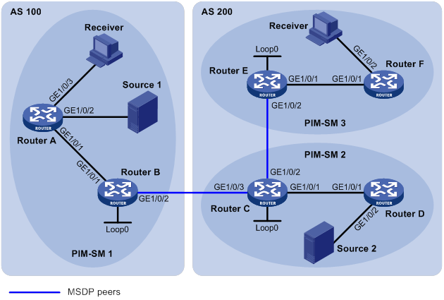
Table 13 Interface and IP address assignment
|
Device |
Interface |
IP address |
Device |
Interface |
IP address |
|
Router A |
10.110.1.2/24 |
||||
|
Router A |
10.110.2.1/24 |
Router D |
|||
|
Router A |
10.110.3.1/24 |
||||
|
Router B |
10.110.1.1/24 |
Router E |
|||
|
Router B |
192.168.1.1/24 |
Router E |
|||
|
Router B |
1.1.1.1/32 |
||||
|
Router C |
10.110.4.1/24 |
Router F |
|||
|
Router C |
192.168.3.1/24 |
— |
|||
|
Router C |
192.168.1.2/24 |
— |
|||
|
Router C |
2.2.2.2/32 |
|
|
|
Configuration procedure
1. Assign an IP address and subnet mask to each interface according to Figure 53. (Details not shown.)
2. Configure OSPF on the routers in the ASs. (Details not shown.)
3. Enable IP multicast routing, enable PIM-SM and IGMP, and configure a PIM-SM domain border:
# On Router A, enable IP multicast routing.
<RouterA> system-view
[RouterA] multicast routing
[RouterA-mrib] quit
# Enable PIM-SM on GigabitEthernet 1/0/1 and GigabitEthernet 1/0/2.
[RouterA] interface gigabitethernet 1/0/1
[RouterA-GigabitEthernet1/0/1] pim sm
[RouterA-GigabitEthernet1/0/1] quit
[RouterA] interface gigabitethernet 1/0/2
[RouterA-GigabitEthernet1/0/2] pim sm
[RouterA-GigabitEthernet1/0/2] quit
# Enable IGMP on the receiver-side interface (GigabitEthernet 1/0/3).
[RouterA] interface gigabitethernet 1/0/3
[RouterA-GigabitEthernet1/0/3] igmp enable
[RouterA-GigabitEthernet1/0/3] quit
# Enable IP multicast routing, PIM-SM, and IGMP on Router B, Router C, Router D, Router E, and Router F in the same way Router A is configured. (Details not shown.)
# Configure a PIM domain border on Router B.
[RouterB] interface gigabitethernet 1/0/2
[RouterB-GigabitEthernet1/0/2] pim bsr-boundary
[RouterB-GigabitEthernet1/0/2] quit
# Configure a PIM domain border separately on Router C and Router E in the same way Router B is configured. (Details not shown.)
4. Configure C-BSRs and C-RPs:
# Configure Loopback 0 on Router B as a C-BSR and a C-RP.
[RouterB] pim
[RouterB-pim] c-bsr 1.1.1.1
[RouterB-pim] c-rp 1.1.1.1
[RouterB-pim] quit
# Configure C-BSRs and C-RPs on Router C and Router E in the same way Router B is configured. (Details not shown.)
5. Configure BGP for mutual route redistribution between BGP and OSPF:
# On Router B, configure an EBGP peer and redistribute OSPF routes.
[RouterB] bgp 100
[RouterB-bgp] router-id 1.1.1.1
[RouterB-bgp] peer 192.168.1.2 as-number 200
[RouterB-bgp] address-family ipv4
[RouterB-bgp-ipv4] import-route ospf 1
[RouterB-bgp-ipv4] peer 192.168.1.2 enable
[RouterB-bgp-ipv4] quit
[RouterB-bgp] quit
# On Router C, configure an EBGP peer and redistribute OSPF routes.
[RouterC] bgp 200
[RouterC-bgp] router-id 2.2.2.2
[RouterC-bgp] peer 192.168.1.1 as-number 100
[RouterC-bgp] address-family ipv4
[RouterC-bgp-ipv4] import-route ospf 1
[RouterB-bgp-ipv4] peer 192.168.1.1 enable
[RouterC-bgp-ipv4] quit
[RouterC-bgp] quit
# Redistribute BGP routing information into OSPF on Router B.
[RouterB] ospf 1
[RouterB-ospf-1] import-route bgp
[RouterB-ospf-1] quit
# Redistribute BGP routing information into OSPF on Router C.
[RouterC] ospf 1
[RouterC-ospf-1] import-route bgp
[RouterC-ospf-1] quit
6. Configure MSDP peers:
# Configure an MSDP peer on Router B.
[RouterB] msdp
[RouterB-msdp] peer 192.168.1.2 connect-interface gigabitethernet 1/0/2
[RouterB-msdp] quit
# Configure MSDP peers on Router C.
[RouterC] msdp
[RouterC-msdp] peer 192.168.1.1 connect-interface gigabitethernet 1/0/3
[RouterC-msdp] peer 192.168.3.2 connect-interface gigabitethernet 1/0/2
[RouterC-msdp] quit
# Configure an MSDP peer on Router E.
[RouterE] msdp
[RouterE-msdp] peer 192.168.3.1 connect-interface gigabitethernet 1/0/2
[RouterE-msdp] quit
Verifying the configuration
# Display information about BGP IPv4 unicast peers or peer groups on Router B.
[RouterB] display bgp peer ipv4
BGP local router ID: 1.1.1.1
Local AS number: 100
Total number of peers: 1 Peers in established state: 1
* - Dynamically created peer
Peer AS MsgRcvd MsgSent OutQ PrefRcv Up/Down State
192.168.1.2 200 24 21 0 4 00:13:09 Established
# Display information about BGP IPv4 unicast peers or peer groups on Router C.
[RouterC] display bgp peer ipv4
BGP local router ID: 2.2.2.2
Local AS number: 200
Total number of peers: 1 Peers in established state: 1
* - Dynamically created peer
Peer AS MsgRcvd MsgSent OutQ PrefRcv Up/Down State
192.168.1.1 100 18 16 0 2 00:12:04 Established
# Display the BGP IPv4 unicast routing table on Router C.
[RouterC] display bgp routing-table ipv4
Total number of routes: 5
BGP local router ID is 2.2.2.2
Status codes: * - valid, > - best, d - dampened, h - history,
s - suppressed, S - stale, i - internal, e - external
Origin: i - IGP, e - EGP, ? - incomplete
Network NextHop MED LocPrf PrefVal Path/Ogn
* > 3.3.3.3/32 192.168.3.2 1 32768 ?
* >e 10.110.2.0/24 192.168.1.1 2 0 100
* >e 10.110.3.0/24 192.168.1.1 2 0 100
* > 10.110.5.0/24 10.110.4.2 2 32768 ?
* > 10.110.6.0/24 192.168.3.2 2 32768 ?
* > 10.110.7.0/24 192.168.3.2 3 32768 ?
# Verify that hosts in PIM-SM 1 and PIM-SM 3 can receive the multicast data from Source 1 and Source 2. (Details not shown.)
# Display brief information about MSDP peer groups on Router B.
[RouterB] display msdp brief
Configured Established Listen Connect Shutdown Disabled
1 1 0 0 0 0
Peer address State Up/Down time AS SA count Reset count
192.168.1.2 Established 00:12:19 ? 13 0
# Display brief information about MSDP peer groups on Router C.
[RouterC] display msdp brief
[RouterC] display msdp brief
Configured Established Listen Connect Shutdown Disabled
2 2 0 0 0 0
Peer address State Up/Down time AS SA count Reset count
192.168.3.2 Established 00:15:19 ? 8 0
192.168.1.1 Established 00:06:11 ? 13 0
# Display brief information about MSDP peer groups on Router E.
[RouterE] display msdp brief
[RouterE] display msdp brief
Configured Established Listen Connect Shutdown Disabled
1 1 0 0 0 0
Peer address State Up/Down time AS SA count Reset count
192.168.3.1 Established 01:12:19 ? 8 0
# Display detailed MSDP peer information on Router B.
[RouterB] display msdp peer-status
MSDP Peer 192.168.1.2; AS 200
Description:
Information about connection status:
State: Established
Up/down time: 00:15:47
Resets: 0
Connection interface: GigabitEthernet1/0/2 (192.168.1.1)
Received/sent messages: 16/16
Discarded input messages: 0
Discarded output messages: 0
Elapsed time since last connection or counters clear: 00:17:40
Mesh group peer joined: momo
Last disconnect reason: Hold timer expired with truncated message
Truncated packet: 5 bytes in buffer, type: 1, length: 20, without packet time: 75s
Information about (Source, Group)-based SA filtering policy:
Import policy: None
Export policy: None
Information about SA-Requests:
Policy to accept SA-Requests: None
Sending SA-Requests status: Disable
Minimum TTL to forward SA with encapsulated data: 0
SAs learned from this peer: 0, SA cache maximum for the peer: 4294967295
Input queue size: 0, Output queue size: 0
Counters for MSDP messages:
RPF check failure: 0
Incoming/outgoing SA: 0/0
Incoming/outgoing SA-Request: 0/0
Incoming/outgoing SA-Response: 0/0
Incoming/outgoing Keepalive: 867/867
Incoming/outgoing Notification: 0/0
Incoming/outgoing Traceroutes in progress: 0/0
Incoming/outgoing Traceroute reply: 0/0
Incoming/outgoing Unknown: 0/0
Incoming/outgoing data packet: 0/0
Inter-AS multicast configuration by leveraging static RPF peers
Network requirements
As shown in Figure 54:
· The network has two ASs: AS 100 and AS 200. OSPF runs within each AS. BGP runs between the two ASs.
· PIM-SM 1 belongs to AS 100, and PIM-SM 2 and PIM-SM 3 belong to AS 200. Each PIM-SM domain has a minimum of one multicast source or receiver.
To meet the network requirements, perform the following tasks:
· Configure Loopback 0 as the C-BSR and C-RP of the related PIM-SM domain on Router A, Router D and Router G.
· According to the peer-RPF forwarding rule, the routers accept SA messages that pass the filtering policy from its static RPF peers. To share multicast source information among PIM-SM domains without changing the unicast topology structure, configure MSDP peering relationships for the RPs of the PIM-SM domains and configure the static RPF peering relationships.
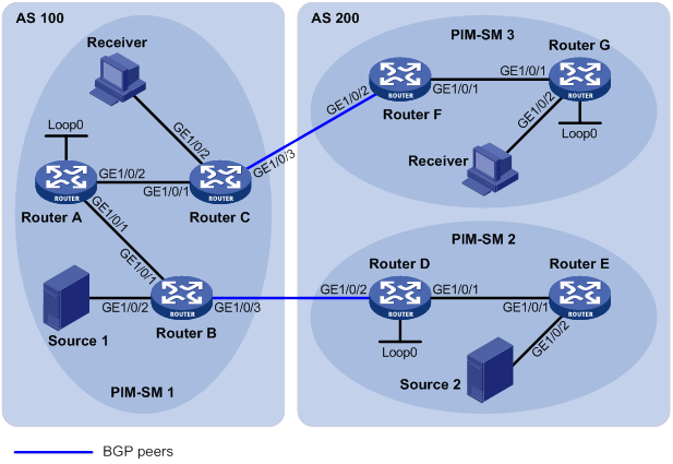
Table 14 Interface and IP address assignment
|
Device |
Interface |
IP address |
Device |
Interface |
IP address |
|
Source 1 |
— |
192.168.1.100/24 |
Router D |
10.110.5.1/24 |
|
|
Source 2 |
— |
192.168.3.100/24 |
Router D |
10.110.3.2/24 |
|
|
Router A |
10.110.1.1/24 |
Router D |
2.2.2.2/32 |
||
|
Router A |
10.110.2.1/24 |
Router E |
10.110.5.2/24 |
||
|
Router A |
1.1.1.1/32 |
Router E |
192.168.3.1/24 |
||
|
Router B |
10.110.1.2/24 |
Router F |
10.110.6.1/24 |
||
|
Router B |
192.168.1.1/24 |
Router F |
10.110.4.2/24 |
||
|
Router B |
10.110.3.1/24 |
Router G |
10.110.6.2/24 |
||
|
Router C |
10.110.2.2/24 |
Router G |
192.168.4.1/24 |
||
|
Router C |
192.168.2.1/24 |
Router G |
3.3.3.3/32 |
||
|
Router C |
10.110.4.1/24 |
Configuration procedure
1. Assign an IP address and subnet mask to each interface according to Table 14. (Details not shown.)
2. Configure OSPF on the routers in the ASs. (Details not shown.)
3. Enable IP multicast routing, PIM-SM, and IGMP, and configure PIM-SM domain borders:
# On Router C, enable IP multicast routing.
<RouterC> system-view
[RouterC] multicast routing
[RouterC-mrib] quit
# Enable PIM-SM on each interface, and enable IGMP on the receiver-side interface GigabitEthernet 1/0/2.
[RouterC] interface gigabitethernet 1/0/1
[RouterC-GigabitEthernet1/0/1] pim sm
[RouterC-GigabitEthernet1/0/1] quit
[RouterC] interface gigabitethernet 1/0/2
[RouterC-GigabitEthernet1/0/2] igmp enable
[RouterC-GigabitEthernet1/0/2] quit
[RouterC] interface gigabitethernet 1/0/3
[RouterC-GigabitEthernet1/0/3] pim sm
[RouterC-GigabitEthernet1/0/3] quit
# Configure Router A, Router B, Router D, Router E, Router F, and Router G in the same way Router C is configured. (Details not shown.)
# On Router B, configure the PIM domain borders.
[RouterB] interface gigabitethernet 1/0/3
[RouterB-GigabitEthernet1/0/3] pim bsr-boundary
[RouterB-GigabitEthernet1/0/3] quit
# Configure the PIM domain borders on Router C, Router D, and Router F in the same way Router B is configured. (Details not shown.)
4. Configure C-BSRs and C-RPs:
# On Router A, configure Loopback 0 as a C-BSR and a C-RP.
[RouterA] pim
[RouterA-pim] c-bsr 1.1.1.1
[RouterA-pim] c-rp 1.1.1.1
[RouterA-pim] quit
# Configure C-BSRs and C-RPs on Router D and Router G in the same way Router A is configured. (Details not shown.)
5. Configure BGP, and redistribute BGP routing information into OSPF and OSPF routing information into BGP:
# On Router B, configure an EBGP peer, and redistribute OSPF routes and direct routes.
[RouterB] bgp 100
[RouterB-bgp] router-id 1.1.1.2
[RouterB-bgp] peer 10.110.3.2 as-number 200
[RouterB-bgp] address-family ipv4 unicast
[RouterB-bgp-ipv4] peer 10.110.3.2 enable
[RouterB-bgp-ipv4] import-route ospf 1
[RouterB-bgp-ipv4] import-route direct
[RouterB-bgp-ipv4] quit
[RouterB-bgp] quit
# On Router D, configure an EBGP peer, and redistribute OSPF routes and direct routes.
[RouterD] bgp 200
[RouterD-bgp] router-id 2.2.2.2
[RouterD-bgp] peer 10.110.3.1 as-number 100
[RouterD-bgp] address-family ipv4 unicast
[RouterD-bgp-ipv4] peer 10.110.3.1 enable
[RouterD-bgp-ipv4] import-route ospf 1
[RouterD-bgp-ipv4] import-route direct
[RouterD-bgp-ipv4] quit
[RouterD-bgp] quit
# On Router C, configure an EBGP peer, and redistribute OSPF routes and direct routes.
[RouterC] bgp 100
[RouterC-bgp] router-id 1.1.1.3
[RouterC-bgp] peer 10.110.4.2 as-number 200
[RouterC-bgp] address-family ipv4 unicast
[RouterC-bgp-ipv4] peer 10.110.4.2 enable
[RouterC-bgp-ipv4] import-route ospf 1
[RouterC-bgp-ipv4] import-route direct
[RouterC-bgp-ipv4] quit
[RouterC-bgp] quit
# On Router F, configure an EBGP peer, and redistribute OSPF routes and direct routes.
[RouterF] bgp 200
[RouterF-bgp] router-id 3.3.3.1
[RouterF-bgp] peer 10.110.4.1 as-number 100
[RouterF-bgp] address-family ipv4 unicast
[RouterF-bgp-ipv4] peer 10.110.4.1 enable
[RouterF-bgp-ipv4] import-route ospf 1
[RouterF-bgp-ipv4] import-route direct
[RouterF-bgp-ipv4] quit
[RouterF-bgp] quit
# On Router B, redistribute BGP routes and direct routes into OSPF.
[RouterB] ospf 1
[RouterB-ospf-1] import-route bgp
[[RouterB-ospf-1] import-route direct
[RouterB-ospf-1] quit
# On Router D, redistribute BGP routes and direct routes into OSPF.
[RouterD] ospf 1
[RouterD-ospf-1] import-route bgp
[RouterD-ospf-1] import-route direct
[RouterD-ospf-1] quit
# On Router C, redistribute BGP routes and direct routes into OSPF
[RouterC] ospf 1
[RouterC-ospf-1] import-route bgp
[RouterC-ospf-1] import-route direct
[RouterC-ospf-1] quit
# On Router F, redistribute BGP routes and direct routes into OSPF.
[RouterF] ospf 1
[RouterF-ospf-1] import-route bgp
[RouterF-ospf-1] import-route direct
[RouterF-ospf-1] quit
6. Configure MSDP peers and static RPF peers:
# On Router A, configure Router D and Router G as the MSDP peers and static RPF peers.
[RouterA] ip prefix-list list-dg permit 10.110.0.0 16 greater-equal 16 less-equal 32
[RouterA] msdp
[RouterA-msdp] peer 10.110.3.2 connect-interface gigabitethernet 1/0/1
[RouterA-msdp] peer 10.110.6.2 connect-interface gigabitethernet 1/0/2
[RouterA-msdp] static-rpf-peer 10.110.3.2 rp-policy list-dg
[RouterA-msdp] static-rpf-peer 10.110.6.2 rp-policy list-dg
[RouterA-msdp] quit
# On Router D, configure Router A as the MSDP peer and static RPF peer.
[RouterD] ip prefix-list list-a permit 10.110.0.0 16 greater-equal 16 less-equal 32
[RouterD] msdp
[RouterD-msdp] peer 10.110.1.1 connect-interface gigabitethernet 1/0/2
[RouterD-msdp] static-rpf-peer 10.110.1.1 rp-policy list-a
[RouterD-msdp] quit
# On Router G, configure Router A as the MSDP peer and static RPF peer.
[RouterG] ip prefix-list list-a permit 10.110.0.0 16 greater-equal 16 less-equal 32
[RouterG] msdp
[RouterG-msdp] peer 10.110.2.1 connect-interface gigabitethernet 1/0/1
[RouterG-msdp] static-rpf-peer 10.110.2.1 rp-policy list-a
[RouterG-msdp] quit
Verifying the configuration
# Display the BGP peering relationships on Router A.
[RouterA] display bgp peer
No information is output, because no BGP peering relationship has been established between Router A and Router D, or between Router A and Router G. This means that the unicast topology is not changed.
# Display brief information about MSDP peers on Router A.
[RouterA] display msdp brief
Configured Established Listen Connect Shutdown Disabled
2 2 0 0 0 0
Peer address State Up/Down time AS SA count Reset count
10.110.3.2 Established 01:07:08 ? 8 0
10.110.6.2 Established 00:16:39 ? 13 0
# Display brief information about MSDP peers on Router D.
[RouterD] display msdp brief
Configured Established Listen Connect Shutdown Disabled
1 1 0 0 0 0
Peer address State Up/Down time AS SA count Reset count
10.110.1.1 Established 01:07:09 ? 8 0
# Display brief information about MSDP peers on Router G.
[RouterG] display msdp brief
Configured Established Listen Connect Shutdown Disabled
1 1 0 0 0 0
Peer address State Up/Down time AS SA count Reset count
10.110.2.1 Established 00:16:40 ? 13 0
# Verify that receivers in PIM-SM 1 and PIM-SM 3 can receive the multicast data from Source 1 and Source 2 to a multicast group. (Details not shown.)
Anycast RP configuration
Network requirements
As shown in Figure 55, OSPF runs within the domain to provide unicast routes.
Configure the Anycast RP application so that the receiver-side DRs and the source-side DRs can initiate a join process to their respective RPs that are topologically closest to them.
Configure the router IDs of Router B and Router D as 1.1.1.1 and 2.2.2.2, respectively. Set up an MSDP peering relationship between Router B and Router D.
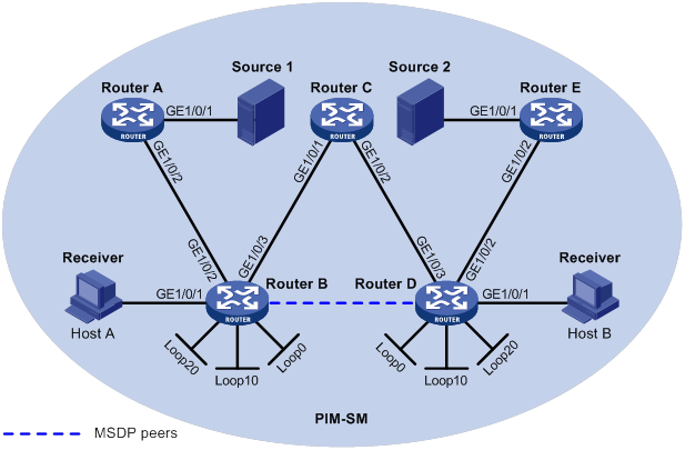
Table 15 Interface and IP address assignment
|
Device |
Interface |
IP address |
Device |
Interface |
IP address |
|
Source 1 |
— |
10.110.5.100/24 |
|||
|
Source 2 |
— |
10.110.6.100/24 |
Router C |
||
|
Router A |
10.110.5.1/24 |
||||
|
Router A |
10.110.2.2/24 |
Router D |
|||
|
Router B |
10.110.1.1/24 |
Router D |
|||
|
Router B |
10.110.2.1/24 |
Router D |
|||
|
Router B |
192.168.1.1/24 |
Router D |
|||
|
Router B |
1.1.1.1/32 |
Router D |
|||
|
Router B |
3.3.3.3/32 |
||||
|
Router B |
10.1.1.1/32 |
Router E |
Configuration procedure
1. Assign an IP address and subnet mask to each interface according to Figure 55. (Details not shown.)
2. Configure OSPF on the routers in the PIM-SM domain. (Details not shown.)
3. Enable IP multicast routing, IGMP, and PIM-SM:
# On Router B, enable IP multicast routing.
<RouterB> system-view
[RouterB] multicast routing
[RouterB-mrib] quit
# Enable IGMP on the receiver-side interface (GigabitEthernet 1/0/1).
[RouterB] interface gigabitethernet 1/0/1
[RouterB-GigabitEthernet1/0/1] igmp enable
[RouterB-GigabitEthernet1/0/1] quit
# Enable PIM-SM on the other interfaces.
[RouterB] interface gigabitethernet 1/0/2
[RouterB-GigabitEthernet1/0/2] pim sm
[RouterB-GigabitEthernet1/0/2] quit
[RouterB] interface gigabitethernet 1/0/3
[RouterB-GigabitEthernet1/0/3] pim sm
[RouterB-GigabitEthernet1/0/3] quit
[RouterB] interface loopback 0
[RouterB-LoopBack0] pim sm
[RouterB-LoopBack0] quit
[RouterB] interface loopback 10
[RouterB-LoopBack10] pim sm
[RouterB-LoopBack10] quit
[RouterB] interface loopback 20
[RouterB-LoopBack20] pim sm
[RouterB-LoopBack20] quit
# Enable IP multicast routing, IGMP, and PIM-SM on Router A, Router C, Router D, and Router E in the same way Router B is configured. (Details not shown.)
4. Configure Anycast RP, C-BSRs, and C-RPs:
# On Router B, set the Anycast RP address to 10.1.1.1, configure Loopback 10 as a C-BSR, and configure Loopback 20 as a C-RP.
[RouterB] pim
[RouterB-pim] anycast-rp 10.1.1.1 10.1.1.1
[RouterB-pim] c-bsr 3.3.3.3
[RouterB-pim] c-rp 10.1.1.1
[RouterB-pim] quit
# Configure a C-BSR and a C-RP on Router D in the same way Router B is configured. (Details not shown.)
5. Configure MSDP peers:
# Configure an MSDP peer on Loopback 0 of Router B.
[RouterB] msdp
[RouterB-msdp] originating-rp loopback 0
[RouterB-msdp] peer 2.2.2.2 connect-interface loopback 0
[RouterB-msdp] quit
# Configure an MSDP peer on Loopback 0 of Router D.
[RouterD] msdp
[RouterD-msdp] originating-rp loopback 0
[RouterD-msdp] peer 1.1.1.1 connect-interface loopback 0
[RouterD-msdp] quit
Verifying the configuration
# Display brief information about MSDP peers on Router B.
[RouterB] display msdp brief
Configured Established Listen Connect Shutdown Disabled
1 1 0 0 0 0
Peer address State Up/Down time AS SA count Reset count
2.2.2.2 Established 00:00:13 ? 0 0
# Display brief information about MSDP peers on Router D.
[RouterD] display msdp brief
Configured Established Listen Connect Shutdown Disabled
1 1 0 0 0 0
Peer address State Up/Down time AS SA count Reset count
1.1.1.1 Established 00:00:13 ? 0 0
# Send an IGMP report from Host A to join multicast group 225.1.1.1. (Details not shown.)
# Send multicast data from Source 1 10.110.5.100/24 to multicast group 225.1.1.1. (Details not shown.)
# Display the PIM routing table on Router D.
[RouterD] display pim routing-table
No information is output on Router D.
# Display the PIM routing table on Router B.
[RouterB] display pim routing-table
Total 1 (*, G) entry; 1 (S, G) entry
(*, 225.1.1.1)
RP: 10.1.1.1 (local)
Protocol: pim-sm, Flag: WC
UpTime: 00:15:04
Upstream interface: Register-Tunnel0
Upstream neighbor: NULL
RPF prime neighbor: NULL
Downstream interface information:
Total number of downstream interfaces: 1
1: GigabitEthernet1/0/1
Protocol: igmp, UpTime: 00:15:04, Expires: -
(10.110.5.100, 225.1.1.1)
RP: 10.1.1.1 (local)
Protocol: pim-sm, Flag: SPT 2MSDP ACT
UpTime: 00:46:28
Upstream interface: GigabitEthernet1/0/2
Upstream neighbor: 10.110.2.2
RPF prime neighbor: 10.110.2.2
Downstream interface information:
Total number of downstream interfaces: 1
1: GigabitEthernet1/0/1
Protocol: pim-sm, UpTime: - , Expires: -
The output shows that Router B now acts as the RP for Source 1 and Host A.
# Send an IGMP leave message from Host A to leave multicast group 225.1.1.1. (Details not shown.),
# Send an IGMP report from Host B to join multicast group 225.1.1.1. (Details not shown.)
# Send multicast data from Source 2 to multicast group 225.1.1.1. (Details not shown.)
# Display the PIM routing table on Router B.
[RouterB] display pim routing-table
No information is output on Router B.
# Display PIM routing information on Router D.
[RouterD] display pim routing-table
Total 1 (*, G) entry; 1 (S, G) entry
(*, 225.1.1.1)
RP: 10.1.1.1 (local)
Protocol: pim-sm, Flag: WC
UpTime: 00:12:07
Upstream interface: Register-Tunnel0
Upstream neighbor: NULL
RPF prime neighbor: NULL
Downstream interface information:
Total number of downstream interfaces: 1
1: GigabitEthernet1/0/1
Protocol: igmp, UpTime: 00:12:07, Expires: -
(10.110.6.100, 225.1.1.1)
RP: 10.1.1.1 (local)
Protocol: pim-sm, Flag: SPT 2MSDP ACT
UpTime: 00:40:22
Upstream interface: GigabitEthernet1/0/2
Upstream neighbor: 10.110.4.2
RPF prime neighbor: 10.110.4.2
Downstream interface information:
Total number of downstream interfaces: 1
1: GigabitEthernet1/0/1
Protocol: pim-sm, UpTime: - , Expires: -
The output shows that Router D now acts as the RP for Source 2 and Host B.
SA message filtering configuration
Network requirements
As shown in Figure 56:
· OSPF runs within and among the PIM-SM domains to provide unicast routing.
· Set up an MSDP peering relationship between Router A and Router C and between Router C and Router D.
· Source 1 sends multicast data to multicast groups 225.1.1.0/30 and 226.1.1.0/30. Source 2 sends multicast data to multicast group 227.1.1.0/30.
Configure SA message policies to meet the following requirements:
· Host A and Host B receive the multicast data only addressed to multicast groups 225.1.1.0/30 and 226.1.1.0/30.
· Host C receives the multicast data only addressed to multicast groups 226.1.1.0/30 and 227.1.1.0/30.
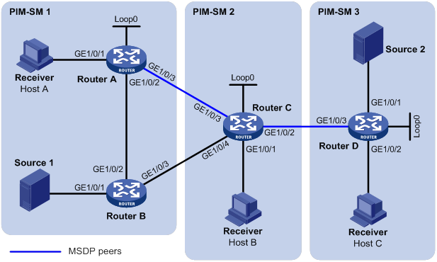
Table 16 Interface and IP address assignment
|
Device |
Interface |
IP address |
Device |
Interface |
IP address |
|
— |
|||||
|
— |
Router C |
||||
|
Router C |
|||||
|
Router A |
Router C |
||||
|
Router A |
Router C |
||||
|
Router A |
|||||
|
Router D |
|||||
|
Router B |
Router D |
||||
|
Router B |
Router D |
Configuration procedure
1. Assign an IP address and subnet mask to each interface according to Figure 56. (Details not shown.)
2. Configure OSPF on the routers in the PIM-SM domains. (Details not shown.)
3. Enable IP multicast routing, IGMP, and PIM-SM, and configure a PIM domain border:
# On Router A, enable IP multicast routing.
<RouterA> system-view
[RouterA] multicast routing
[RouterA-mrib] quit
# Enable IGMP on the receiver-side interface (GigabitEthernet 1/0/1).
[RouterA] interface gigabitethernet 1/0/1
[RouterA-GigabitEthernet1/0/1] igmp enable
[RouterA-GigabitEthernet1/0/1] quit
# Enable PIM-SM on the other interfaces.
[RouterA] interface gigabitethernet 1/0/2
[RouterA-GigabitEthernet1/0/2] pim sm
[RouterA-GigabitEthernet1/0/2] quit
[RouterA] interface gigabitethernet 1/0/3
[RouterA-GigabitEthernet1/0/3] pim sm
[RouterA-GigabitEthernet1/0/3] quit
[RouterA] interface loopback 0
[RouterA-LoopBack0] pim sm
[RouterA-LoopBack0] quit
# Enable IP multicast routing, IGMP, and PIM-SM on Router B, Router C, and Router D in the same way Router A is configured. (Details not shown.)
# Configure PIM domain borders on Router C.
[RouterC] interface gigabitethernet 1/0/2
[RouterC-GigabitEthernet1/0/2] pim bsr-boundary
[RouterC-GigabitEthernet1/0/2] quit
[RouterC] interface gigabitethernet 1/0/3
[RouterC-GigabitEthernet1/0/3] pim bsr-boundary
[RouterC-GigabitEthernet1/0/3] quit
[RouterC] interface gigabitethernet 1/0/4
[RouterC-GigabitEthernet1/0/4] pim bsr-boundary
[RouterC-GigabitEthernet1/0/4] quit
# Configure PIM domain borders on Router A, Router B, and Router D in the same way Router C is configured. (Details not shown.)
4. Configure C-BSRs and C-RPs:
# Configure Loopback 0 on Router A as a C-BSR and a C-RP.
[RouterA] pim
[RouterA-pim] c-bsr 1.1.1.1
[RouterA-pim] c-rp 1.1.1.1
[RouterA-pim] quit
# Configure C-BSRs and C-RPs on Router C and Router D in the same way Router A is configured. (Details not shown.)
5. Configure MSDP peers:
# Configure an MSDP peer on Router A.
[RouterA] msdp
[RouterA-msdp] peer 192.168.1.2 connect-interface gigabitethernet 1/0/3
[RouterA-msdp] quit
# Configure MSDP peers on Router C.
[RouterC] msdp
[RouterC-msdp] peer 192.168.1.1 connect-interface gigabitethernet 1/0/3
[RouterC-msdp] peer 10.110.5.2 connect-interface gigabitethernet 1/0/2
[RouterC-msdp] quit
# Configure an MSDP peer on Router D.
[RouterD] msdp
[RouterD-msdp] peer 10.110.5.1 connect-interface gigabitethernet 1/0/3
[RouterD-msdp] quit
6. Configure SA message policies:
# Configure an SA accepting and forwarding policy on Router C so that Router C will not forward SA messages for (Source 1, 225.1.1.0/30) to Router D.
[RouterC] acl advanced 3001
[RouterC-acl-ipv4-adv-3001] rule deny ip source 10.110.3.100 0 destination 225.1.1.0 0.0.0.3
[RouterC-acl-ipv4-adv-3001] rule permit ip source any destination any
[RouterC-acl-ipv4-adv-3001] quit
[RouterC] msdp
[RouterC-msdp] peer 10.110.5.2 sa-policy export acl 3001
[RouterC-msdp] quit
# Configure an SA creation policy on Router D so that Router D will not create SA messages for Source 2.
[RouterD] acl basic 2001
[RouterD-acl-ipv4-basic-2001] rule deny source 10.110.6.100 0
[RouterD-acl-ipv4-basic-2001] quit
[RouterD] msdp
[RouterD-msdp] import-source acl 2001
[RouterD-msdp] quit
Verifying the configuration
# Display the (S, G) entries in the SA message cache on Router C.
[RouterC] display msdp sa-cache
MSDP Total Source-Active Cache - 8 entries
Matched 8 entries
Source Group Origin RP Pro AS Uptime Expires
10.110.3.100 225.1.1.0 1.1.1.1 ? ? 02:03:30 00:05:31
10.110.3.100 225.1.1.1 1.1.1.1 ? ? 02:03:30 00:05:31
10.110.3.100 225.1.1.2 1.1.1.1 ? ? 02:03:30 00:05:31
10.110.3.100 225.1.1.3 1.1.1.1 ? ? 02:03:30 00:05:31
10.110.3.100 226.1.1.0 1.1.1.1 ? ? 02:03:30 00:05:31
10.110.3.100 226.1.1.1 1.1.1.1 ? ? 02:03:30 00:05:31
10.110.3.100 226.1.1.2 1.1.1.1 ? ? 02:03:30 00:05:31
10.110.3.100 226.1.1.3 1.1.1.1 ? ? 02:03:30 00:05:31
# Display the (S, G) entries in the SA message cache on Router D.
[RouterD] display msdp sa-cache
MSDP Total Source-Active Cache - 4 entries
Matched 4 entries
Source Group Origin RP Pro AS Uptime Expires
10.110.3.100 226.1.1.0 1.1.1.1 ? ? 00:32:53 00:05:07
10.110.3.100 226.1.1.1 1.1.1.1 ? ? 00:32:53 00:05:07
10.110.3.100 226.1.1.2 1.1.1.1 ? ? 00:32:53 00:05:07
10.110.3.100 226.1.1.3 1.1.1.1 ? ? 00:32:53 00:05:07
Troubleshooting MSDP
This section describes common MSDP problems and how to troubleshoot them.
MSDP peers stay in disabled state
Symptom
The configured MSDP peers stay in disabled state.
Solution
To resolve the problem:
1. Use the display ip routing-table command to verify that the unicast route between the routers is reachable.
2. Verify that a unicast route is available between the two routers that will become MSDP peers to each other.
3. Use the display current-configuration command to verify that the local interface address and the MSDP peer address of the remote router are the same.
4. If the problem persists, contact H3C Support.
No SA entries exist in the router's SA message cache
Symptom
MSDP fails to send (S, G) entries through SA messages.
Solution
To resolve the problem:
1. Use the display ip routing-table command to verify that the unicast route between the routers is reachable.
2. Verify that a unicast route is available between the two routers that will become MSDP peers to each other.
3. Verify the configuration of the import-source command and its ipv4-acl-number argument, and make sure the ACL rule filters appropriate (S, G) entries.
4. If the problem persists, contact H3C Support.
No exchange of locally registered (S, G) entries between RPs
Symptom
RPs fail to exchange their locally registered (S, G) entries with one another in the Anycast RP application.
Solution
To resolve the problem:
1. Use the display ip routing-table command to verify that the unicast route between the routers is reachable.
2. Verify that a unicast route is available between the two routers that will establish an MSDP peering relationship.
3. Verify the configuration of the originating-rp command. In the Anycast RP application environment, use the originating-rp command to configure the RP address in the SA messages, which must be the local interface address.
4. Verify that the C-BSR address is different from the Anycast RP address.
5. If the problem persists, contact H3C Support.
Configuring multicast VPN
Overview
As shown in Figure 57:
· VPN A contains Site 1, Site 3, and Site 5.
· VPN B contains Site 2, Site 4, and Site 6.
Figure 57 Typical VPN networking diagram
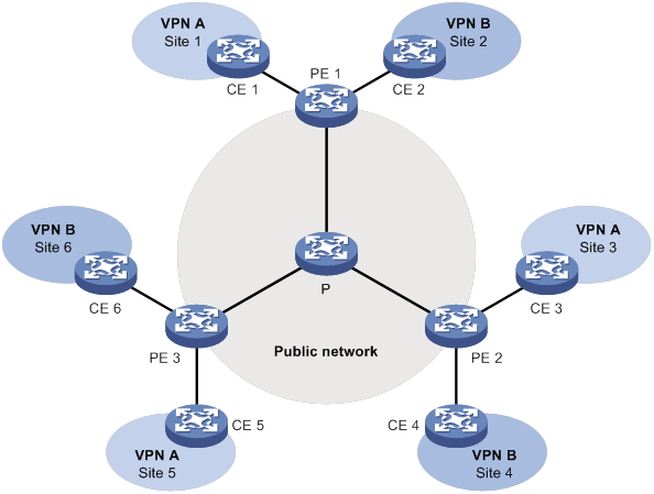
A VPN has the following types of devices:
· Provider (P) device—Core device on a service provider network. A P device does not directly connect to CE devices.
· Provider edge (PE) device—Edge device on a service provider network. A PE device directly connects to one or more customer edge (CE) devices and processes VPN routing.
· CE device—Edge device on a customer network. A CE device implements route distribution on the customer network. The device can be a router, a switch, or a host.
As shown in Figure 57, the network that runs multicast VPN provides independent multicast services for the public network, VPN A, and VPN B. The multicast device PE supports multiple VPN instances and acts as multiple independent multicast devices. Each VPN forms a plane, and all these planes are isolated from each other. For example, in Figure 57, PE 1 supports the public network, VPN A, and VPN B. You can consider these instances on PE 1 to be independent virtual devices, which are PE 1', PE 1", and PE 1'". Each virtual device works on a plane, as shown in Figure 58.
Figure 58 Multicast in multiple VPN instances
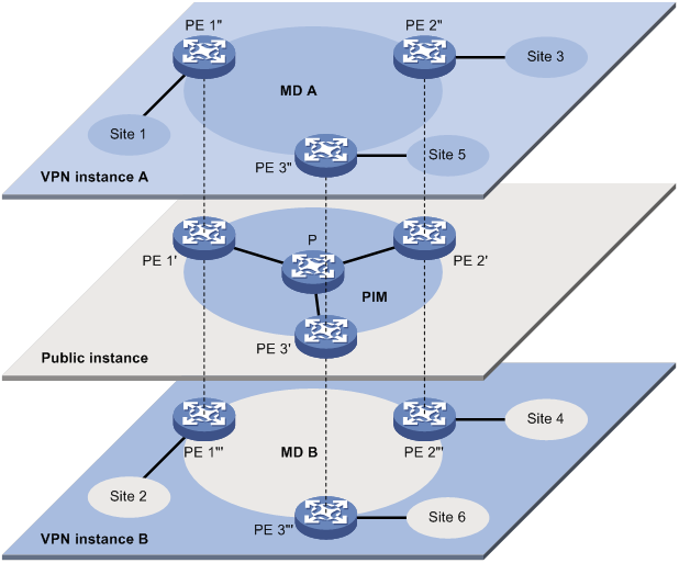
Through multicast VPN, multicast data of VPN A for a multicast group can only arrive at receiver hosts in Site 1, Site 3, and Site 5 of VPN A. The stream is multicast in these sites and on the public network.
The prerequisites for implementing multicast VPN are as follows:
1. Within each site, multicast for a single VPN instance is supported.
2. On the public network, multicast for the public network is supported.
3. The PE devices support multiple VPN instances as follows:
? Connecting with different sites through VPN instances and supporting multicast for each VPN instance.
? Connecting with the public network and supporting multicast for the public network.
? Supporting information exchange and data conversion between the public network and VPNs.
The device implements multicast VPN by using the multicast domain (MD) method. This multicast VPN implementation is referred to as MD VPN.
The most significant advantage of MD VPN is that it requires only the PE devices to support multiple VPN instances. There is no need to upgrade CE devices and P devices or change their original PIM configurations. Therefore, the MD VPN solution is transparent to CE devices and P devices.
MD VPN overview
The basic MD VPN concepts are described in Table 17.
Table 17 Basic MD VPN concepts
|
Concept |
Description |
|
An MD is a set of PE devices that are in the same VPN instance. Each MD uniquely corresponds to a VPN instance. |
|
|
Multicast distribution tree (MDT) |
An MDT is a multicast distribution tree constructed by all PE devices in the same VPN. MDT types include default-MDT and data-MDT. |
|
Multicast tunnel (MT) |
An MT is a tunnel that interconnects all PEs in an MD for delivering VPN traffic within the MD. |
|
Multicast tunnel interface (MTI) |
An MTI is the entrance or exit of an MT, equivalent to an entrance or exit of an MD. PE devices use the MTI to access the MT. An MTI handles only multicast packets, not unicast packets. The MTI interfaces are automatically created when the MD for the VPN instance is created. |
|
Default-group |
On the public network, each MD is assigned a unique multicast address, called a default-group. A default-group is the unique identifier of an MD on the public network. It helps build the default-MDT for an MD on the public network. |
|
Default-MDT |
A default-MDT uses a default-group address as its group address. In a VPN, the default-MDT is uniquely identified by the default-group. A default-MDT is automatically created after the default-group is specified and will always exist on the public network, regardless of the presence of any multicast services on the public network or the VPN. |
|
Data-group |
When the multicast traffic of a VPN reaches or exceeds a threshold, the ingress PE device assigns it an independent multicast address called data-group. It also notifies other PE devices that they must use this address to forward the multicast traffic for that VPN. This initiates the switchover to the data-MDT. |
|
Data-MDT |
A data-MDT is an MDT that uses a data-group as it group address. At MDT switchover, PE devices with downstream receivers join a data-group, building a data-MDT. The ingress PE forwards the encapsulated VPN multicast traffic along the data-MDT over the public network. |
Introduction to MD VPN
The main points in MD VPN implementation are as follows:
· The public network of the service provider supports multicast:
? The PE devices must support the public network and multiple VPN instances.
? Each instance runs PIM independently.
VPN multicast traffic between the PE devices and the CE devices is transmitted on a per-VPN-instance basis. However, the public network multicast traffic between the PE devices and the P devices is transmitted through the public network.
· An MD logically defines the transmission boundary of the multicast traffic of a specific VPN over the public network. It also physically identifies all the PE devices that support that VPN instance on the public network. Different VPN instances correspond to different MDs.
As shown in Figure 58, the ellipse area in the center of each VPN instance plane represents an MD that provides services for a particular VPN instance. All the VPN multicast traffic in that VPN is transmitted within that MD.
· Inside an MD, all the private traffic is transmitted through the MT. The process of multicast traffic transmission through an MT is as follows:
a. The local PE device encapsulates a VPN multicast packet into a public network multicast packet.
b. The encapsulated multicast packet is sent by the PE device and travels over the public network.
c. After receiving the multicast packet, the remote PE device decapsulates the multicast packet to get the original VPN multicast packet.
· The local PE device sends VPN data out of the MTI. The remote PE devices receive the private data from their MTI interfaces.
As shown in Figure 59, you can think of an MD as a private data transmission pool and an MTI as an entrance or exit of the pool. The local PE device puts the private data into the transmission pool (MD) through the entrance (MTI). The transmission pool automatically duplicates the private data and transmits the data to each exit (MTI) of the transmission pool. Then, a remote PE device that needs the data can get it from its exit (MTI).
Figure 59 Relationship between PIM on the public network and an MD in a VPN instance
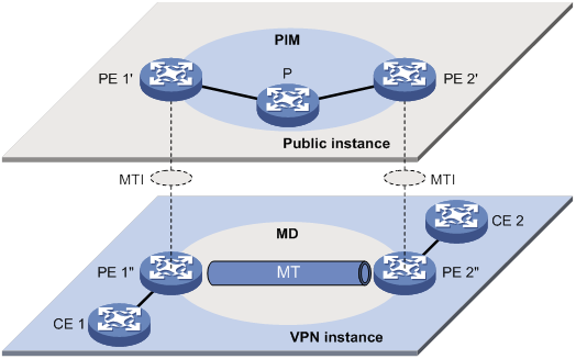
· Each VPN instance is assigned a unique default-group address. The VPN data is transparent to the public network.
A PE device encapsulates a VPN multicast packet (a multicast protocol packet or a multicast data packet) into a public network multicast packet. The default-group address is used as the public network multicast group. Then, the PE sends this multicast packet to the public network.
· A default-group corresponds to a unique MD. For each default-group, a unique default-MDT is constructed through the public network resources for multicast data forwarding. All the VPN multicast packets transmitted in this VPN are forwarded along this default-MDT, regardless of which PE device they used to enter the public network.
· An MD is assigned a unique data-group range for MDT switchover. When the rate of a VPN multicast stream that entered the public network at a PE device reaches or exceeds the switchover threshold, the PE does the following:
? Selects an address that is least used from the data-group range.
? Uses the address to encapsulate the multicast packets for that VPN.
· All the PE devices on the network monitor the forwarding rate on the default-MDT.
a. When the rate of a VPN multicast stream that entered the public network at a specific PE device exceeds the threshold, the PE device creates an MDT switchover message. The message travels to the downstream along the default-MDT. This causes a data-MDT to be built by using the data-group between that PE device and the remote PE devices with downstream receivers.
b. After a data-delay period has passed, an MDT switchover process starts. All VPN multicast packets that have entered the public network through that PE device are not encapsulated with the default-group address. They are encapsulated into public network multicast packets with the data-group address. Then they are switched from the default-MDT to the data-MDT.
For more information about MDT switchover, see "MDT switchover."
|
|
NOTE: A VPN uniquely corresponds to an MD and an MD provides services for only one VPN, which is called a one-to-one relationship. Such a relationship exists between VPN, MD, MTI, default-group, and the data-group range. |
PIM neighboring relationships in MD VPN
Figure 60 PIM neighboring relationships in MD VPN
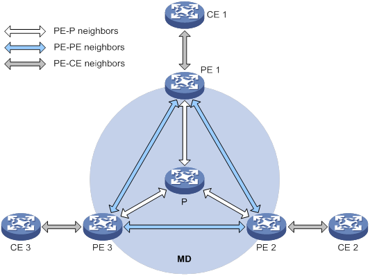
PIM neighboring relationships are established between two or more directly interconnected devices on the same subnet. As shown in Figure 60, the following types of PIM neighboring relationships exist in MD VPN:
· PE-P PIM neighboring relationship—Established between the public network interface on a PE device and the peer interface on the P device over the link.
· PE-PE PIM neighboring relationship—Established between PE devices that are in the same VPN instance after they receive the PIM hello packets.
· PE-CE PIM neighboring relationship—Established between a PE interface that is bound with the VPN instance and the peer interface on the CE device over the link.
Protocols and standards
RFC 6037, Cisco Systems' Solution for Multicast in BGP/MPLS IP VPNs
How MD VPN works
This section describes default-MDT establishment, multicast traffic delivery based on the default-MDT, and inter-AS MD VPN implementation.
For a VPN instance, multicast data transmission on the public network is transparent. The VPN data is exchanged between the MTIs of the local PE and the remote PE. This implements the seamless transmission of the VPN data over the public network. However, the multicast data transmission process (the MDT transmission process) over the public network is very complicated.
Default-MDT establishment
The multicast routing protocol running on the public network can be PIM-DM, PIM-SM, BIDIR-PIM, or PIM-SSM. The process of creating a default-MDT is different in these PIM modes.
Default-MDT establishment in a PIM-DM network
Figure 61 Default-MDT establishment in a PIM-DM network

As shown in Figure 61, PIM-DM is enabled on the network, and all the PE devices support VPN instance A. The process of establishing a default-MDT is as follows:
1. To establish PIM neighboring relationships with PE 2 and PE 3 through the MTI for the VPN instance A, PE 1 does the following:
a. Encapsulates the PIM protocol packet of the private network into a public network multicast data packet. PE 1 does this by specifying the source address as the IP address of the MD source interface and the multicast group address as the default-group address.
b. Sends the multicast data packet to the public network.
For other PE devices that support VPN instance A as default-group members, PE 1 of VPN instance A initiates a flood-prune process in the entire public network. A (11.1.1.1, 239.1.1.1) state entry is created on each device along the path on the public network. This forms an SPT with PE 1 as the root, and PE 2 and PE 3 as leaves.
2. At the same time, PE 2 and PE 3 separately initiate a similar flood-prune process.
Finally, three independent SPTs are established in the MD, constituting the default-MDT in the PIM-DM network.
Default-MDT establishment in a PIM-SM network
Figure 62 Default-MDT establishment in a PIM-SM network
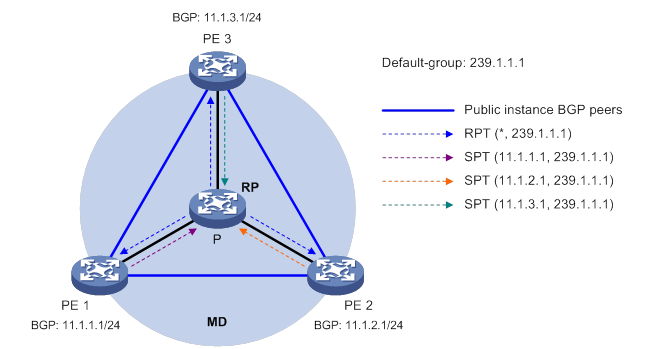
As shown in Figure 62, PIM-SM is enabled on the network, and all the PE devices support VPN instance A. The process of establishing a default-MDT is as follows:
1. PE 1 initiates a join to the public network RP by specifying the multicast group address as the default-group address in the join message. A (*, 239.1.1.1) state entry is created on each device along the path on the public network.
2. At the same time, PE 2 and PE 3 separately initiate a similar join process.
Finally, an RPT is established in the MD, with the public network RP as the root and PE 1, PE 2, and PE 3 as leaves.
3. To establish PIM neighboring relationships with PE 2 and PE 3 through the MTI for the VPN instance A, PE 1 does the following:
a. Encapsulates the PIM protocol packet of the private network into a public network multicast data packet. PE 1 does this by specifying the source address as the IP address of the MD source interface and the multicast group address as the default-group address.
b. Sends the multicast data packet to the public network.
The public network interface of PE 1 registers the multicast source with the public network RP, and the public network RP initiates a join to PE 1. A (11.1.1.1, 239.1.1.1) state entry is created on each device along the path on the public network.
4. At the same time, PE 2 and PE 3 separately initiate a similar register process.
Finally, three SPTs between the PE devices and the RP are established in the MD.
In the PIM-SM network, the RPT, or the (*, 239.1.1.1) tree, and the three independent SPTs constitute the default-MDT.
Default-MDT establishment in a BIDIR-PIM network
Figure 63 Default-MDT establishment in a BIDIR-PIM network
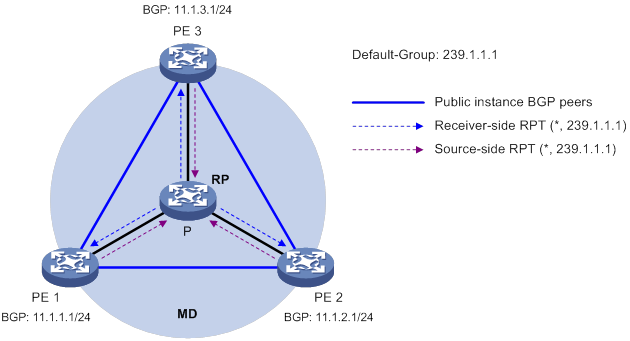
As shown in Figure 63, BIDIR-PIM runs on the network, and all the PE devices support VPN instance A. The process of establishing a default-MDT is as follows:
1. PE 1 initiates a join to the public network RP by specifying the multicast group address as the default-group address in the join message. A (*, 239.1.1.1) state entry is created on each device along the path on the public network.
At the same time, PE 2 and PE 3 separately initiate a similar join process. Finally, a receiver-side RPT is established in the MD, with the public network RP as the root and PE 1, PE 2, and PE 3 as leaves.
2. PE 1 sends a multicast packet with the default-group address as the multicast group address. The DF of each network segment on the public network forwards the multicast packet to the RP. Each device on the path creates a (*, 239.1.1.1) state entry.
At the same time, PE 2 and PE 3 separately initiate a similar process. Finally, three source-side RPTs are established in the MD, with PE 1, PE 2, and PE 3 as the roots and as the public network RP as the leave.
3. The receiver-side RPT and the three source-side RPTs constitute the default-MDT in the BIDIR-PIM network.
Default-MDT establishment in a PIM-SSM network
Figure 64 Default-MDT establishment in a PIM-SSM network
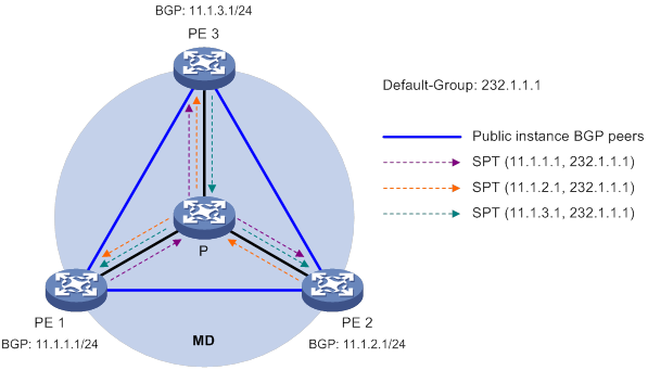
As shown in Figure 64, PIM-SSM runs on the network, and all the PE devices support VPN instance A. The process of establishing a default-MDT is as follows:
1. PE 1, PE 2, and PE 3 exchange MDT route information (including BGP interface address and the default-group address) through BGP.
2. PE 1 sends a subscribe message to PE 2 and PE 3. Each device on the public network creates an (S, G) entry. An SPT is established in the MD with PE 1 as the root and PE 2 and PE 3 as the leaves.
At the same time, PE 2 and PE 3 separately initiate a similar process, and establish an SPT with itself as the root and the other PEs as the leaves.
3. The three independent SPTs constitute the default-MDT in the PIM-SSM network.
In PIM-SSM, the term "subscribe message" refers to a join message.
Default-MDT characteristics
No matter which PIM mode is running on the public network, the default-MDT has the following characteristics:
· All PE devices that support the same VPN instance join the default-MDT.
Default-MDT-based delivery
The default-MDT delivers multicast protocol packets and multicast data packets differently.
Multicast protocol packet delivery
To forward the multicast protocol packets of a VPN over the public network, the local PE device encapsulates them into public network multicast data packets. These packets are transmitted along the default-MDT and are then decapsulated on the remote PE device to go into the normal protocol procedure. Finally, a distribution tree is established across the public network.
The following describes how multicast protocol packets are forwarded in different circumstances:
· If the VPN network runs PIM-DM or PIM-SSM:
? Hello packets are forwarded through MTI interfaces to establish PIM neighboring relationships.
? A flood-prune process (in PIM-DM) or a join process (in PIM-SSM) is initiated across the public network to establish an SPT across the public network.
· If the VPN network runs PIM-SM:
? Hello packets are forwarded through MTI interfaces to establish PIM neighboring relationships.
? If the receivers and the VPN RP are in different sites, a join process is initiated across the public network to establish an RPT.
? If the multicast source and the VPN RP are in different sites, a registration process is initiated across the public network to establish an SPT.
· If the VPN network runs BIDIR-PIM:
? Hello packets are forwarded through MTI interfaces to establish PIM neighboring relationships.
? If the receivers and the VPN RP are in different sites, a join process is initiated across the public network to establish a receiver-side RPT.
? If the multicast sources and the VPN RP are in different sites, join processes are initiated across the public network to establish source-side RPTs.
|
|
NOTE: PIM mode must be the same for all interfaces that belong to the same VPN, including those interfaces that are bound with the VPN instance and the MTI interfaces on PE devices. |
As shown in Figure 65:
· PIM-SM is running in both the public network and the VPN network.
· Receiver for the VPN multicast group G (225.1.1.1) in Site 2 is attached to CE 2.
· CE 1 of Site 1 acts as the RP for group G (225.1.1.1).
· The default-group address used to forward public network data is 239.1.1.1.
Figure 65 Transmission of multicast protocol packets
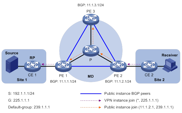
The multicast protocol packet is delivered as follows:
1. Receiver sends an IGMP report to CE 2 to join the multicast group G. CE 2 creates a local state entry (*, 225.1.1.1) and sends a join message to the VPN RP (CE 1).
2. After receiving the join message from CE 2, the VPN instance on PE 2 creates a state entry (*, 225.1.1.1) and specifies the MTI interface as the upstream interface. The VPN instance on PE 2 considers the join message to have been sent out of the MTI interface, because step 3 is transparent to the VPN instance.
3. PE 2 encapsulates the join message into a public network multicast data packet (11.1.2.1, 239.1.1.1) by using the GRE method. In this multicast data packet, the source address is the MD source interface IP address 11.1.2.1, and the destination address is the default-group address 239.1.1.1. PE 2 then forwards this packet to the public network.
4. The default-MDT forwards the multicast data packet (11.1.2.1, 239.1.1.1) to the public network instance on all the PE devices. After receiving this packet, every PE device decapsulates it to get the original join message to be sent to the VPN RP. Then, each PE device examines the VPN RP address in the join message. If the VPN RP is in the site to which a PE device is connected, the PE passes the join message to the VPN instance on the PE. Otherwise, the PE discards the join message.
5. When receiving the join message, the VPN instance on PE 1 considers the received message to be from the MTI. PE 1 creates a local state entry (*, 225.1.1.1), with the downstream interface being the MTI and the upstream interface being the one that leads to CE 1. At the same time, the VPN instance sends a join message to CE 1, which is the VPN RP.
6. After receiving the join message from the VPN instance on PE 1, CE 1 creates a local state entry (*, 225.1.1.1) or updates the entry if the entry already exists.
By now, the construction of an RPT across the public network is completed.
Multicast data packet delivery
After the default-MDT is established, the multicast source forwards the VPN multicast data to the receivers in each site along the default-MDT. The VPN multicast packets are encapsulated into public network multicast packets on the local PE device, and transmitted along the default-MDT. Then, they are decapsulated on the remote PE device and transmitted in that VPN site.
VPN multicast data packets are forwarded across the public network differently in the following circumstances:
· If PIM-DM or PIM-SSM is running in the VPN, the multicast source forwards multicast data packets to the receivers along the VPN SPT across the public network.
· When PIM-SM is running in the VPN:
? Before the RPT-to-SPT switchover, if the multicast source and the VPN RP are in different sites, the VPN multicast data packets travel to the VPN RP along the VPN SPT across the public network. If the VPN RP and the receivers are in different sites, the VPN multicast data packets travel to the receivers along the VPN RPT over the public network.
? After the RPT-to-SPT switchover, if the multicast source and the receivers are in different sites, the VPN multicast data packets travel to the receivers along the VPN SPT across the public network.
· When BIDIR-PIM is running in the VPN, if the multicast source and the VPN RP are in different sites, the multicast source sends multicast data to the VPN RP across the public network along the source-side RPT. If the VPN RP and the receivers are in different sites, the multicast data packets travel to the receivers across the public network along the receiver-side RPT.
For more information about RPT-to-SPT switchover, see "Configuring PIM."
The following example explains how multicast data packets are delivered based on the default-MDT when PIM-DM is running in both the public network and the VPN network.
As shown in Figure 66:
· PIM-DM is running in both the public network and the VPN sites.
· Receiver of the VPN multicast group G (225.1.1.1) in Site 2 is attached to CE 2.
· Source in Site 1 sends multicast data to multicast group (G).
· The default-group address used to forward public network multicast data is 239.1.1.1.
Figure 66 Multicast data packet delivery
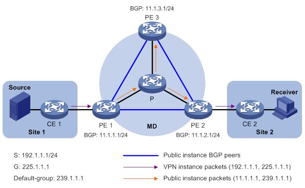
A VPN multicast data packet is delivered across the public network as follows:
1. Source sends a VPN multicast data packet (192.1.1.1, 225.1.1.1) to CE 1.
2. CE 1 forwards the VPN multicast data packet along an SPT to PE 1, and the VPN instance on PE 1 examines the MVRF.
If the outgoing interface list of the forwarding entry contains an MTI, PE 1 processes the VPN multicast data packet as described in step 3. The VPN instance on PE 1 considers the VPN multicast data packet to have been sent out of the MTI, because step 3 is transparent to it.
3. PE 1 encapsulates the VPN multicast data packet into a public network multicast packet (11.1.1.1, 239.1.1.1) by using the GRE method. The source IP address of the packet is the MD source interface 11.1.1.1, and the destination address is the default-group address 239.1.1.1. PE 1 then forwards it to the public network.
4. The default-MDT forwards the multicast data packet (11.1.1.1, 239.1.1.1) to the public network instance on all the PE devices. After receiving this packet, every PE device decapsulates it to get the original VPN multicast data packet, and passes it to the corresponding VPN instance. If a PE device has a downstream interface for an SPT, it forwards the VPN multicast packet down the SPT. Otherwise, it discards the packet.
By now, the process of transmitting a VPN multicast data packet across the public network is completed.
MDT switchover
Switching from default-MDT to data-MDT
When a multicast packet of a VPN is transmitted through the default-MDT on the public network, the packet is forwarded to all PE devices that support that VPN instance. This occurs whether or not any active receivers exist in the attached sites. When the rate of the multicast traffic of that VPN is high, multicast data might get flooded on the public network. This increases the bandwidth use and brings extra burden on the PE devices.
To optimize multicast transmission of large VPN multicast traffic that enters the public network, the MD solution introduces a dedicated data-MDT. The data-MDT is built between the PE devices that connect VPN multicast receivers and multicast sources. When specific network criteria are met, a switchover from the default-MDT to the data-MDT occurs to forward VPN multicast traffic to receivers.
The process of default-MDT to data-MDT switchover is as follows:
1. The source-side PE device (PE 1, for example) periodically examines the forwarding rate of the VPN multicast traffic. The default-MDT switches to the data-MDT only when the following criteria are both met:
? The VPN multicast data has passed the ACL rule filtering for default-MDT to data-MDT switchover.
? The traffic rate of the VPN multicast stream has exceeded the switchover threshold and stayed higher than the threshold for a certain length of time.
2. PE 1 selects a least-used address from the data-group range. Then, it sends an MDT switchover message to all the other PE devices down the default-MDT. This message contains the VPN multicast source address, the VPN multicast group address, and the data-group address.
3. Each PE device that receives this message examines whether it interfaces with a VPN that has receivers of that VPN multicast stream.
If so, it joins the data-MDT rooted at PE 1. Otherwise, it caches the message and will join the data-MDT when it has attached receivers.
4. After sending the MDT switchover message, PE 1 starts the data-delay timer. When the timer expires, PE 1 uses the default-group address to encapsulate the VPN multicast data. The multicast data is then forwarded down the data-MDT.
5. After the multicast traffic is switched from the default-MDT to the data-MDT, PE 1 continues sending MDT switchover messages periodically. Subsequent PE devices with attached receivers can then join the data-MDT. When a downstream PE device no longer has active receivers attached to it, it leaves the data-MDT.
For a given VPN instance, the default-MDT and the data-MDT are both forwarding tunnels in the same MD. A default-MDT is uniquely identified by a default-group address, and a data-MDT is uniquely identified by a data-group address. Each default-group is uniquely associated with a data-group range.
Backward switching from data-MDT to default-MDT
After the VPN multicast traffic is switched to the data-MDT, the multicast traffic conditions might change and no longer meet the switchover criterion. In this case, PE 1, as in the preceding example, initiates a backward MDT switchover process when any of the following criteria are met:
· The traffic rate of the VPN multicast data has dropped below the switchover threshold. In addition, the traffic rate has stayed lower than the threshold for a certain length of time (known as the data-holddown period).
· The associated data-group range is changed, and the data-group address for encapsulating the VPN multicast data is out of the new address range.
· The ACL rule for controlling the switchover from the default-MDT to the data-MDT has changed, and the VPN multicast data fails to pass the new ACL rule.
Inter-AS MD VPN
In an inter-AS VPN networking scenario, VPN sites are located in multiple ASs. These sites must be interconnected. Inter-AS VPN provides the following solutions:
· VRF-to-VRF connections between ASBRs—This solution is also called inter-AS option A.
· EBGP redistribution of labeled VPN-IPv4 routes between ASBRs—ASBRs advertise VPN-IPv4 routes to each other through MP-EBGP. This solution is also called inter-AS option B.
· Multihop EBGP redistribution of labeled VPN-IPv4 routes between PE routers—PEs advertise VPN-IPv4 routes to each other through MP-EBGP. This solution is also called inter-AS option C.
For more information about the three inter-AS VPN solutions, see "Configuring MPLS L3VPN."
Based on these solutions, there are three ways to implement inter-AS MD VPN:
· MD VPN inter-AS option A
· MD VPN inter-AS option B
· MD VPN inter-AS option C
MD VPN inter-AS option A
As shown in Figure 67:
· Two VPN instances are in AS 1 and AS 2.
· PE 3 and PE 4 are ASBRs for AS 1 and AS 2, respectively.
· PE 3 and PE 4 are interconnected through their respective VPN instance and treat each other as a CE device.
Figure 67 MD VPN inter-AS option A
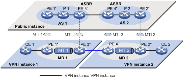
To implement MD VPN inter-AS option A, a separate MD must be created in each AS. Multicast data is transmitted between the VPNs in different ASs through the MDs.
Multicast packets of VPN instance 1 are delivered as follows:
1. CE 1 forwards the multicast packet of VPN instance 1 to PE 1.
2. PE 1 encapsulates the multicast packet into a public network packet and forwards it to PE 3 through the MTI interface in MD 1.
3. PE 3 considers PE 4 as a CE device of VPN instance 1, so PE 3 forwards the multicast packet to PE 4.
4. PE 4 considers PE 3 as a CE device of VPN instance 2, so it forwards the multicast packet to PE 2 through the MTI interface in MD 2 on the public network.
5. PE 2 forwards the multicast packet to CE 2.
Because only VPN multicast data is forwarded between ASBRs, different PIM modes can run within different ASs. However, the same PIM mode must run on all interfaces that belong to the same VPN (including interfaces with VPN bindings on ASBRs).
MD VPN inter-AS option B
In MD VPN inter-AS option B, RPF vector and BGP connector are introduced:
· RPF vector—Attribute encapsulated in a PIM join message. It is the next hop of BGP MDT route from the local PE device to the remote PE device. Typically, it is the ASBR in the local AS.
When a device receives the join message with the RPF vector, it first checks whether the RPF vector is its own IP address. If so, the device removes the RPF vector, and sends the message to its upstream neighbor according to the route to the remote PE device. Otherwise, it keeps the RPF vector, looks up the route to the RPF vector, and sends the message to the next hop of the route. In this way, the PIM message can be forwarded across the ASs and an MDT is established.
· BGP connector—Attribute shared by BGP peers when they exchange VPNv4 routes. It is the IP address of the remote PE device.
The local PE device fills the upstream neighbor address field with the BGP connector in a join message. This ensures that the message can pass the RPF check on the remote PE device after it travels along the MT.
To implement MD VPN inter-AS option B, only one MD needs to be established for the two ASs. VPN multicast data is transmitted between different ASs on the public network within this MD.
As shown in Figure 68:
· A VPN network involves AS 1 and AS 2.
· PE 3 and PE 4 are the ASBRs for AS 1 and AS 2, respectively.
· PE 3 and PE 4 are interconnected through MP-EBGP and treat each other as a P device.
· PE 3 and PE 4 advertise VPN-IPv4 routes to each other through MP-EBGP.
· An MT is established between PE 1 and PE 2 for delivering VPN multicast traffic across the ASs.
Figure 68 MD VPN inter-AS option B
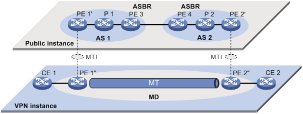
The establishment of the MDT on the public network is as follows:
1. PE 1 originates a PIM join message to join the SPT rooted at PE 2. In the join message, the upstream neighbor address is the IP address of PE 2 (the BGP connector). The RPF vector attribute is the IP address of PE 3. PE 1 encapsulates the join message as a public network packet and forwards it through the MTI.
2. P 1 determines that the RPF vector is not an IP address of its own. It looks up the routing table for a route to PE 3, and forwards the packet to PE 3.
3. PE 3 removes the RPF vector because the RPF vector is its own IP address. It fails to find a BGP MDT route to PE 2, so it encapsulates a new RPF vector (IP address of PE 4) in the packet and forwards it to PE 4.
4. PE 4 removes the RPF vector because the RPF vector is its own IP address. It has a local route to PE 2, so it forwards the packet to P 2, which is the next hop of the route to PE 2.
5. P 2 sends the packet to PE 2.
6. PE 2 receives the packet on the MTI and decapsulates the packet. The receiving interface is the RPF interface of the RPF route back to PE 1 for the join message, and the join message passes the RPF check. The SPT from PE 1 to PE 2 is established.
When PE 1 joins the SPT rooted at PE 1, PE 2 also initiates a join process to the SPT rooted at PE 1. A MDT is established when the two SPTs are finished.
MD VPN inter-AS option C
As shown in Figure 69:
· A VPN network involves AS 1 and AS 2.
· PE 3 and PE 4 are the ASBRs for AS 1 and AS 2, respectively.
· PE 3 and PE 4 are interconnected through MP-EBGP and treat each other as a P device.
· PEs in different ASs establish a multihop MP-EBGP session to advertise VPN-IPv4 routes to each other.
Figure 69 MD VPN inter-AS option C
To implement MD VPN inter-AS option C, only one MD needs to be created for the two ASs. Multicast data is transmitted between the two ASs through the MD.
Multicast packets are delivered as follows:
1. CE 1 forwards the VPN instance multicast packet to PE 1.
2. PE 1 encapsulates the multicast packet into a public network multicast packet and forwards it to PE 3 through the MTI interface on the public network.
3. PE 3 and PE 4 are interconnected through MP-EBGP, so PE 3 forwards the public network multicast packet to PE 4 along the VPN IPv4 route.
4. The public network multicast packet arrives at the MTI interface of PE 2 in AS 2. PE 2 decapsulates the public network multicast packet and forwards the VPN multicast packet to CE 2.
M6VPE
The multicast IPv6 VPN provider edge (M6VPE) feature enables PE devices to transmit IPv6 multicast traffic of a VPN instance over the public network. Only the IPv4 network is available for the backbone network.
As shown in Figure 70, the public network runs IPv4 protocols, and sites of VPN instance VPN A run IPv6 multicast protocols. To transmit IPv6 multicast traffic between CE 1 and CE 2, configure M6VPE on the PE devices.
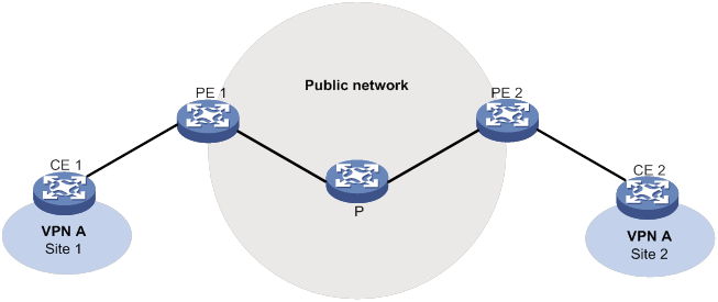
IPv6 multicast traffic forwarding over the IPv4 public network is as follows:
1. CE 1 forwards an IPv6 multicast packet for VPN instance VPN A to PE 1.
2. PE 1 encapsulates the IPv6 multicast packet with an IPv4 packet header and transmits the IPv4 packet in the IPv4 backbone network.
3. PE 2 decapsulates the IPv4 packet and forwards the IPv6 multicast packet to CE 2.
Feature and hardware compatibility
The following matrix shows the feature and hardware compatibility:
|
Hardware |
Multicast VPN compatibility |
|
MSR810/810-W/810-W-DB/810-LM/810-W-LM/810-10-PoE/810-LM-HK/810-W-LM-HK |
Yes |
|
MSR810-LMS/810-LUS |
No |
|
MSR2600-6-X1/2600-10-X1 |
Yes |
|
MSR 2630 |
Yes |
|
MSR3600-28/3600-51 |
Yes |
|
MSR3600-28-SI/3600-51-SI |
No |
|
MSR3610-X1/3610-X1-DP/3610-X1-DC/3610-X1-DP-DC |
Yes |
|
MSR 3610/3620/3620-DP/3640/3660 |
Yes |
|
MSR5620/5660/5680 |
Yes |
|
Hardware |
Multicast VPN compatibility |
|
MSR810-LM-GL |
Yes |
|
MSR810-W-LM-GL |
Yes |
|
MSR830-6EI-GL |
Yes |
|
MSR830-10EI-GL |
Yes |
|
MSR830-6HI-GL |
Yes |
|
MSR830-10HI-GL |
Yes |
|
MSR2600-6-X1-GL |
Yes |
|
MSR3600-28-SI-GL |
No |
IPv6-related parameters are not supported on the following routers:
· MSR810.
· MSR810-W.
· MSR810-W-DB.
· MSR810-LM.
· MSR810-W-LM.
· MSR810-10-PoE.
· MSR810-LM-HK.
· MSR810-W-LM-HK.
Multicast VPN configuration task list
|
Tasks at a glance |
|
· (Required.) Enabling IP multicast routing for a VPN instance · (Required.) Creating an MD for a VPN instance · (Required.) Create an MD address family · (Required.) Specifying the default-group · (Required.) Specifying the MD source interface · (Optional.) Configuring MDT switchover parameters · (Optional.) Configuring the RPF vector feature · (Optional.) Enabling data-group reuse logging |
|
· (Required.) Configuring BGP MDT peers or peer groups · (Optional.) Configuring a BGP MDT route reflector |
The MTI interfaces are automatically created and bound with the VPN instance when you create an MD for the VPN instance. Follow these guidelines to make sure the MTI interfaces are correctly created.
· The MTI interfaces take effect only after the default-group and the MD source interface are specified and the MD source interface gets the public IP address.
· The PIM mode on the MTI must be the same as the PIM mode running on the VPN instance to which the MTI belongs. When a minimum of one interface on the VPN instance is enabled with PIM, the MTI is enabled with PIM accordingly. When all interfaces on the VPN instance are PIM-disabled, PIM is also disabled on the MTI.
Configuring MD VPN
This section describes how to configure MD VPN.
Configuration prerequisites
Before you configure MD VPN, complete the following tasks:
· Configure a unicast routing protocol on the public network.
· Configure MPLS L3VPN on the public network.
· Configure PIM-DM, PIM-SM, BIDIR-PIM, or PIM-SSM on the public network.
· Determine the VPN instance names and RDs.
· Determine the default-groups.
· Determine the source address for establishing BGP peers.
· Determine the data-group range and the MDT switchover criteria.
· Determine the data-delay period.
· Determine the data-holddown period.
Enabling IP multicast routing for a VPN instance
Before you configure any MD VPN functionality for a VPN instance, you must create a VPN instance and enable IP multicast routing for the VPN instance.
Perform this task on PE devices.
To enable IP multicast routing for a VPN instance:
|
Step |
Command |
Remarks |
|
1. Enter system view. |
system-view |
N/A |
|
2. Create a VPN instance and enter its view. |
ip vpn-instance vpn-instance-name |
By default, no VPN instances exist. For more information about this command, see MPLS Command Reference. |
|
3. Configure an RD for the VPN instance. |
route-distinguisher route-distinguisher |
By default, a VPN instance is not configured with an RD. For more information about this command, see MPLS Command Reference. |
|
4. Return to system view. |
quit |
N/A |
|
5. Enable IP multicast routing for the VPN instance and enter MRIB view of the VPN instance. |
·
Enable IPv4 multicast routing and enter MRIB
view of the VPN instance: ·
Enable IPv6 multicast routing and enter
IPv6 MRIB view of the VPN instance: |
By default, IP multicast routing is disabled in a VPN instance. |
Creating an MD for a VPN instance
To provide multicast services for a VPN instance, you must create an MD for the VPN instance on PE devices that belong to the VPN instance. After the MD is created, the system automatically creates MTIs and binds them with the VPN instance.
A VPN instance supports only one MD.
To create an MD for a VPN instance:
|
Step |
Command |
Remarks |
|
1. Enter system view. |
system-view |
N/A |
|
2. Create an MD for a VPN instance and enter its view. |
multicast-domain vpn-instance vpn-instance-name |
By default, no MD for a VPN instance exists. |
Create an MD address family
You must create an MD IPv4 or IPv6 address family for a VPN instance before you can perform other MD VPN configuration tasks for the VPN instance. For a VPN instance, configurations in MD IPv4 and IPv6 address family views apply to IPv4 and IPv6 multicast packets of the instance, respectively.
Perform this task on PE devices.
To create an MD address family:
|
Step |
Command |
Remarks |
|
1. Enter system view. |
system-view |
N/A |
|
2. Enter MD view of a VPN instance. |
multicast-domain vpn-instance vpn-instance-name |
N/A |
|
3. Create an MD address family and enter its view. |
·
Create an MD IPv4 address family and
enter its view: ·
Create an MD IPv4 address family and
enter its view: |
By default, no MD IPv4 or IPv6 address family exists. |
Specifying the default-group
An MTI of a VPN instance uses the default-group as the destination address to encapsulate multicast packets for the VPN instance.
Configuration restrictions and guidelines
When you specify the default-group, follow these restrictions and guidelines:
· Perform this task on PE devices.
· You must specify the same default-group on all PE devices that belong to the same MD.
· The default-group for an MD must be different from the default-group and the data-group used by any other MD.
· For an MD that transmits both IPv4 and IPv6 multicast packets, you must specify the same default-group in MD IPv4 and IPv6 address family views.
Configuration procedure
To specify the default-group:
|
Step |
Command |
Remarks |
|
1. Enter system view. |
system-view |
N/A |
|
2. Enter MD view. |
multicast-domain vpn-instance vpn-instance-name |
N/A |
|
3. Enter MD address family view. |
·
Enter MD IPv4 address family view: ·
Enter MD IPv6 address family view: |
N/A |
|
4. Specify the default-group. |
default-group group-address |
By default, no default-group exists. |
Specifying the MD source interface
An MTI of a VPN instance uses the IP address of the MD source interface as the source address to encapsulate multicast packets for the VPN instance.
Configuration restrictions and guidelines
When you specify the MD source interface, follow these restrictions and guidelines:
· Perform this task on PE devices.
· For the PE device to obtain correct routing information, you must specify the interface used for establishing BGP peer relationship as the MD source interface.
· For an MD that transmits both IPv4 and IPv6 multicast packets, you must specify the same MD source interface in MD IPv4 and IPv6 address family views.
Configuration procedure
To specify the MD source interface:
|
Step |
Command |
Remarks |
|
1. Enter system view. |
system-view |
N/A |
|
2. Enter MD view. |
multicast-domain vpn-instance vpn-instance-name |
N/A |
|
3. Enter MD address family view. |
·
Enter MD IPv4 address family view: ·
Enter MD IPv6 address family view: |
N/A |
|
4. Specify the MD source interface. |
source interface-type interface-number |
By default, no MD source interface is specified. |
Configuring MDT switchover parameters
In some cases, the traffic rate of the private network multicast data might fluctuate around the MDT switchover threshold. To avoid frequent switching of multicast traffic between the default-MDT and the data-MDT, you can specify a data-delay period and a data-holddown period.
· MDT switchover does not take place immediately after the multicast traffic rate exceeds the switchover threshold. It takes place after a data-delay period, during which the traffic rate must stay higher than the switchover threshold.
· Likewise, a backward switchover does not take place immediately after the multicast traffic rate drops below the MDT switchover threshold. It takes place after a data-holddown period, during which the traffic rate must stay lower than the switchover threshold.
Configuration restrictions and guidelines
When you configure MDT switchover parameters, follow these restrictions and guidelines:
· Perform this task on PE devices.
· On a PE, the data-group range for an MD cannot include the default-group or data-groups of any other MD.
· For an MD that transmits both IPv4 and IPv6 multicast packets, the data-group range in MD IPv4 and IPv6 address family views cannot overlap.
· If the public network runs PIM-SSM, the data-group range for an MD on a PE device can overlap with data-group ranges for other MDs on other PE devices.
Configuration procedure
To configure MDT switchover parameters:
|
Step |
Command |
Remarks |
|
1. Enter system view. |
system-view |
N/A |
|
2. Enter MD view. |
multicast-domain vpn-instance vpn-instance-name |
N/A |
|
3. Enter MD address family view. |
·
Enter MD IPv4 address family view: ·
Enter MD IPv6 address family view: |
N/A |
|
4. Configure the data-group range and the switchover criteria. |
data-group group-address { mask-length | mask } [ threshold threshold-value | acl acl-number ] * |
By default, no data-group range exists, and the default-MDT to data-MDT switchover never occurs. |
|
5. (Optional.) Set the data-delay period. |
data-delay delay |
The default setting is 3 seconds. |
|
6. (Optional.) Set the data-holddown period. |
data-holddown delay |
The default setting is 60 seconds. |
Configuring the RPF vector feature
Enabling the RPF vector feature
This feature enables the device to insert the RPF vector (IP address of the ASBR in the local AS) in PIM join messages for other devices to perform RPF check.
Perform this task on PE devices (except the PE devices that do not have attached receivers).
To enable the RPF vector feature:
|
Step |
Command |
Remarks |
|
1. Enter system view. |
system-view |
N/A |
|
2. Enter MRIB view of a VPN instance. |
N/A |
|
|
3. Enable the RPF vector feature. |
By default, the RPF vector feature is disabled. |
Enabling RPF vector compatibility
This feature enables the device to work with other manufacturers' products on RPF vectors for interoperability purposes. You must enable this feature on all H3C devices on the public network.
To enable RPF vector compatibility:
|
Step |
Command |
Remarks |
|
1. Enter system view. |
system-view |
N/A |
|
2. Enable RPF vector compatibility. |
By default, RPF vector compatibility is disabled. |
Enabling data-group reuse logging
For a given VPN, the number of VPN multicast streams to be switched to data-MDTs might exceed the number of addresses in the data-group range. In this case, the VPN instance on the source-side PE device can reuse the addresses in the address range. With data-group reuse logging enabled, the address reuse information will be logged.
Attributed to the MD module, the group address reuse logging information has a severity level informational. For more information about the logging information, see Network Management and Monitoring Configuration Guide.
Perform this task on PE devices.
To enable data-group reuse logging:
|
Step |
Command |
Remarks |
|
1. Enter system view. |
system-view |
N/A |
|
2. Enter MD view. |
multicast-domain vpn-instance vpn-instance-name |
N/A |
|
3. Enter MD address family view. |
·
Enter MD IPv4 address family view: ·
Enter MD IPv4 address family view: |
N/A |
|
4. Enable data-group reuse logging. |
log data-group-reuse |
By default, data-group reuse logging is disabled. |
Configuring BGP MDT
If PIM-SSM is running on the public network, you must configure BGP MDT.
Configuration prerequisites
Before you configure BGP MDT, complete the following tasks:
· Configure MPLS L3VPN on the public network.
· Configure basic BGP functions on the public network.
· Configure PIM-SSM on the public network.
· Determine the IP addresses of the MDT peers.
· Determine the cluster IDs of the route reflectors.
Configuring BGP MDT peers or peer groups
Configure a BGP MDT peer or peer group on a PE router in BGP IPv4 MDT address family view. Then, the PE router can exchange MDT information with the BGP peer or peer group. MDT information includes the IP address of the PE and default-group to which the PE belongs. On a public network running PIM-SSM, the multicast VPN establishes a default-MDT rooted at the PE (multicast source) based on the MDT information.
Perform this task on PE devices.
To configure a BGP MDT peer or peer group on a PE router:
|
Step |
Command |
Remarks |
|
1. Enter system view. |
system-view |
N/A |
|
2. Enter BGP instance view. |
bgp as-number [ instance instance-name ] |
N/A |
|
3. Create a BGP IPv4 MDT address family and enter its view. |
By default, no BGP IPv4 address family exists. |
|
|
4. Enable the device to exchange MDT routing information with the BGP peer or the peer group. |
peer { group-name | ip-address [ mask-length ] } enable |
By default, the router cannot exchange BGP MDT routing information with a BGP peer or peer group. For more information about this command, see Layer 3—IP Routing Configuration Guide.
Before you configure this command, you must create a BGP peer or peer group in BGP instance view. For more information, see Layer 3—IP Routing Configuration Guide. |
Configuring a BGP MDT route reflector
BGP MDT peers in the same AS must be fully meshed to maintain connectivity. However, when multiple BGP MDT peers exist in an AS, connection establishment among them might result in increased costs. To reduce connections between BGP MDT peers, you can configure one of them as a route reflector and specify other routers as clients.
When clients establish BGP MDT connections with the route reflector, the route reflector forwards (or reflects) BGP MDT routing information between clients. The clients are not required to be fully meshed. To save bandwidth if the clients have been fully meshed, you can disable the routing reflection between clients by using the undo reflect between-clients command.
The route reflector and its clients form a cluster. Typically, a cluster has only one route reflector whose router ID identifies the cluster. However, you can configure several route reflectors in a cluster to improve network reliability. To avoid routing loops, make sure the route reflectors in a cluster have the same cluster ID.
Perform this task on PE devices.
To configure a BGP MDT route reflector:
|
Step |
Command |
Remarks |
|
1. Enter system view. |
system-view |
N/A |
|
2. Enter BGP instance view. |
bgp as-number [ instance instance-name ] |
N/A |
|
3. Enter BGP IPv4 MDT address family view. |
N/A |
|
|
4. Configure the device as a route reflector and specify its peers or peer groups as clients. |
peer { group-name | ip-address [ mask-length ] } reflect-client |
By default, neither route reflectors nor clients exist. |
|
5. (Optional.) Disable route reflection between clients. |
undo reflect between-clients |
By default, route reflection between clients is disabled. For more information about this command, see Layer 3—IP Routing Command Reference. |
|
6. (Optional.) Configure the cluster ID of the route reflector. |
reflector cluster-id { cluster-id | ip-address } |
By default, a route reflector uses its router ID as the cluster ID. For more information about this command, see Layer 3—IP Routing Command Reference. |
Displaying and maintaining multicast VPN
Execute display commands in any view and reset commands in user view.
|
Task |
Command |
|
Display BGP MDT peer group information. |
display bgp [ instance instance-name ] group ipv4 mdt [ group-name group-name ] |
|
Display information about BGP MDT peers or peer groups. |
|
|
Display BGP MDT routing information. |
|
|
Display information about BGP update groups for the BGP IPv4 MDT address family. |
display bgp [ instance instance-name ] update-group ipv4 mdt [ ip-address ] |
|
Display information about data-groups that are received in the MD of a VPN instance for IPv4 multicast transmission. |
display multicast-domain vpn-instance vpn-instance-name data-group receive [ brief | [ active | group group-address | sender source-address | vpn-source-address [ mask { mask-length | mask } ] | vpn-group-address [ mask { mask-length | mask } ] ] * ] |
|
Display information about data-groups that are received in the MD of a VPN instance for IPv6 multicast transmission. |
display multicast-domain vpn-instance vpn-instance-name ipv6 data-group receive [ brief | [ active | group group-address | sender source-address | vpn-source-address [ mask-length ] | vpn-group-address [ mask-length ] ] * ] |
|
Display information about data-groups that are sent in the MD of a VPN instance for IPv4 multicast transmission. |
display multicast-domain vpn-instance vpn-instance-name data-group send [ group group-address | reuse interval | vpn-source-address [ mask { mask-length | mask } ] | vpn-group-address [ mask { mask-length | mask } ] ] * |
|
Display information about data-groups that are sent in the MD of a VPN instance for IPv6 multicast transmission. |
display multicast-domain vpn-instance vpn-instance-name ipv6 data-group send [ group group-address | reuse interval | vpn-source-address [ mask-length ] | vpn-group-address [ mask-length ] ] * |
|
Display information about default-groups for IPv4 multicast transmission. |
display multicast-domain [ vpn-instance vpn-instance-name ] default-group { local | remote } |
|
Display information about default-groups for IPv6 multicast transmission. |
display multicast-domain [ vpn-instance vpn-instance-name ] ipv6 default-group { local | remote } |
|
Reset BGP sessions for BGP IPv4 MDT address family. |
Multicast VPN configuration examples
This section provides examples of configuring multicast VPN on routers.
Intra-AS MD VPN configuration example
Network requirements
As shown in Figure 71, configure intra-AS MD VPN to meet the following requirements:
|
Item |
Network requirements |
|
Multicast sources and receivers |
· In VPN instance a, S 1 is a multicast source, and R 1, R 2, and R 3 are receivers. · In VPN instance b, S 2 is a multicast source, and R 4 is a receiver. · For VPN instance a, the default-group is 239.1.1.1, and the data-group range is 225.2.2.0 to 225.2.2.15. · For VPN instance b, the default-group is 239.2.2.2, and the data-group range is 225.4.4.0 to 225.4.4.15. |
|
VPN instances to which PE interfaces belong |
· PE 1: GigabitEthernet 1/0/2 and GigabitEthernet 1/0/3 belong to VPN instance a. GigabitEthernet 1/0/1 and Loopback 1 belong to the public network. · PE 2: GigabitEthernet 1/0/2 belongs to VPN instance b. GigabitEthernet 1/0/3 belongs to VPN instance a. GigabitEthernet 1/0/1 and Loopback 1 belong to the public network. · PE 3: GigabitEthernet 1/0/2 belongs to VPN instance a. GigabitEthernet 1/0/3 and Loopback 2 belongs to VPN instance b. GigabitEthernet 1/0/1 and Loopback 1 belong to the public network. |
|
Unicast routing protocols and MPLS |
· Configure OSPF on the public network, and configure RIP between the PE devices and the CE devices. · Establish BGP peer connections between PE 1, PE 2, and PE 3 on their respective Loopback 1. · Configure MPLS on the public network. |
|
IP multicast routing |
· Enable IP multicast routing on the P router. · Enable IP multicast routing on the public network instance on PE 1, PE 2, and PE 3. · Enable IP multicast routing for VPN instance a on PE 1, PE 2, and PE 3. · Enable IP multicast routing for VPN instance b on PE 2 and PE 3. · Enable IP multicast routing on CE a1, CE a2, CE a3, CE b1, and CE b2. |
|
IGMP |
· Enable IGMPv2 on GigabitEthernet 1/0/2 of PE 1. · Enable IGMPv2 on GigabitEthernet 1/0/1 of CE a2, CE a3, and CE b2. |
|
PIM |
Enable PIM-SM on the public network and for VPN instances a and b: · Enable PIM-SM on all interfaces of the P router. · Enable PIM-SM on all public and private network interfaces on PE 1, PE 2, and PE 3. · Enable PIM-SM on all interfaces that do not have attached receiver hosts on CE a1, CE a2, CE a3, CE b1, and CE b2. · Configure Loopback 1 of P as a public network C-BSR and C-RP to provide services for all multicast groups. · Configure Loopback 1 of CE a2 as a C-BSR and a C-RP for VPN instance a to provide services for all multicast groups. · Configure Loopback 2 of PE 3 as a C-BSR and a C-RP for VPN instance b to provide services for all multicast groups. |
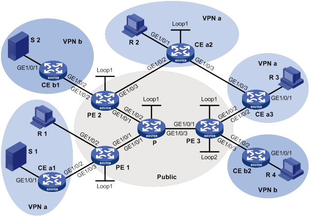
Table 18 Interface and IP address assignment
|
Device |
Interface |
IP address |
Device |
Interface |
IP address |
|
S 1 |
— |
10.110.7.2/24 |
PE 3 |
GE1/0/1 |
192.168.8.1/24 |
|
S 2 |
— |
10.110.8.2/24 |
PE 3 |
GE1/0/2 |
10.110.5.1/24 |
|
R 1 |
— |
10.110.1.2/24 |
PE 3 |
GE1/0/3 |
10.110.6.1/24 |
|
R 2 |
— |
10.110.9.2/24 |
PE 3 |
Loop1 |
1.1.1.3/32 |
|
R 3 |
— |
10.110.10.2/24 |
PE 3 |
Loop2 |
33.33.33.33/32 |
|
R 4 |
— |
10.110.11.2/24 |
CE a1 |
GE1/0/1 |
10.110.7.1/24 |
|
P |
GE1/0/1 |
192.168.6.2/24 |
CE a1 |
GE1/0/2 |
10.110.2.2/24 |
|
P |
GE1/0/2 |
192.168.7.2/24 |
CE a2 |
GE1/0/1 |
10.110.9.1/24 |
|
P |
GE1/0/3 |
192.168.8.2/24 |
CE a2 |
GE1/0/2 |
10.110.4.2/24 |
|
P |
Loop1 |
2.2.2.2/32 |
CE a2 |
GE1/0/3 |
10.110.12.1/24 |
|
PE 1 |
GE1/0/1 |
192.168.6.1/24 |
CE a2 |
Loop1 |
22.22.22.22/32 |
|
PE 1 |
GE1/0/2 |
10.110.1.1/24 |
CE a3 |
GE1/0/1 |
10.110.10.1/24 |
|
PE 1 |
GE1/0/3 |
10.110.2.1/24 |
CE a3 |
GE1/0/2 |
10.110.5.2/24 |
|
PE 1 |
Loop1 |
1.1.1.1/32 |
CE a3 |
GE1/0/3 |
10.110.12.2/24 |
|
PE 2 |
GE1/0/1 |
192.168.7.1/24 |
CE b1 |
GE1/0/1 |
10.110.8.1/24 |
|
PE 2 |
GE1/0/2 |
10.110.3.1/24 |
CE b1 |
GE1/0/2 |
10.110.3.2/24 |
|
PE 2 |
GE1/0/3 |
10.110.4.1/24 |
CE b2 |
GE1/0/1 |
10.110.11.1/24 |
|
PE 2 |
Loop1 |
1.1.1.2/32 |
CE b2 |
GE1/0/2 |
10.110.6.2/24 |
Configuration procedure
1. Configure PE 1:
# Configure a global router ID, and enable IP multicast routing on the public network.
<PE1> system-view
[PE1] router id 1.1.1.1
[PE1] multicast routing
[PE1-mrib] quit
# Configure an LSR ID, and enable LDP globally.
[PE1] mpls lsr-id 1.1.1.1
[PE1] mpls ldp
[PE1-ldp] quit
# Create a VPN instance named a, and configure an RD and route targets for the VPN instance.
[PE1] ip vpn-instance a
[PE1-vpn-instance-a] route-distinguisher 100:1
[PE1-vpn-instance-a] vpn-target 100:1 export-extcommunity
[PE1-vpn-instance-a] vpn-target 100:1 import-extcommunity
[PE1-vpn-instance-a] quit
# Enable IP multicast routing in VPN instance a.
[PE1] multicast routing vpn-instance a
[PE1-mrib-a] quit
# Create an MD for VPN instance a and enter its view.
[PE1] multicast-domain vpn-instance a
# Create an MD IPv4 address family for VPN instance a and enter its view.
[PE1-md-a] address-family ipv4
# Specify the default-group, the MD source interface, and the data-group range for VPN instance a.
[PE1-md-a-ipv4] default-group 239.1.1.1
[PE1-md-a-ipv4] source loopback 1
[PE1-md-a-ipv4] data-group 225.2.2.0 28
[PE1-md-a-ipv4] quit
[PE1-md-a] quit
# Assign an IP address to GigabitEthernet 1/0/1.
[PE1] interface gigabitethernet 1/0/1
[PE1-GigabitEthernet1/0/1] ip address 192.168.6.1 24
# Enable PIM-SM, MPLS, and IPv4 LDP on GigabitEthernet 1/0/1.
[PE1-GigabitEthernet1/0/1] pim sm
[PE1-GigabitEthernet1/0/1] mpls enable
[PE1-GigabitEthernet1/0/1] mpls ldp enable
[PE1-GigabitEthernet1/0/1] quit
# Associate GigabitEthernet 1/0/2 with VPN instance a.
[PE1] interface gigabitethernet 1/0/2
[PE1-GigabitEthernet1/0/2] ip binding vpn-instance a
# Assign an IP address to GigabitEthernet 1/0/2, and enable IGMP on the interface.
[PE1-GigabitEthernet1/0/2] ip address 10.110.1.1 24
[PE1-GigabitEthernet1/0/2] igmp enable
[PE1-GigabitEthernet1/0/2] quit
# Associate GigabitEthernet 1/0/3 with VPN instance a.
[PE1] interface gigabitethernet 1/0/3
[PE1-GigabitEthernet1/0/3] ip binding vpn-instance a
# Assign an IP address to GigabitEthernet 1/0/3, and enable PIM-SM on the interface.
[PE1-GigabitEthernet1/0/3] ip address 10.110.2.1 24
[PE1-GigabitEthernet1/0/3] pim sm
[PE1-GigabitEthernet1/0/3] quit
# Assign an IP address to Loopback 1, and enable PIM-SM on the interface.
[PE1] interface loopback 1
[PE1-LoopBack1] ip address 1.1.1.1 32
[PE1-LoopBack1] pim sm
[PE1-LoopBack1] quit
# Configure BGP.
[PE1] bgp 100
[PE1-bgp-default] group vpn-g internal
[PE1-bgp-default] peer vpn-g connect-interface loopback 1
[PE1-bgp-default] peer 1.1.1.2 group vpn-g
[PE1-bgp-default] peer 1.1.1.3 group vpn-g
[PE1–bgp-default] ip vpn-instance a
[PE1-bgp-default-a] address-family ipv4
[PE1-bgp-default-ipv4-a] import-route rip 2
[PE1-bgp-default-ipv4-a] import-route direct
[PE1-bgp-default-ipv4-a] quit
[PE1-bgp-default-a] quit
[PE1–bgp-default] address-family vpnv4
[PE1–bgp-default-vpnv4] peer vpn-g enable
[PE1–bgp-default-vpnv4] quit
[PE1–bgp-default] quit
# Configure OSPF.
[PE1] ospf 1
[PE1-ospf-1] area 0.0.0.0
[PE1-ospf-1-area-0.0.0.0] network 1.1.1.1 0.0.0.0
[PE1-ospf-1-area-0.0.0.0] network 192.168.6.0 0.0.0.255
[PE1-ospf-1-area-0.0.0.0] quit
[PE1-ospf-1] quit
# Configure RIP.
[PE1] rip 2 vpn-instance a
[PE1-rip-2] network 10.110.1.0 0.0.0.255
[PE1-rip-2] network 10.110.2.0 0.0.0.255
[PE1-rip-2] import-route bgp
[PE1-rip-2] return
2. Configure PE 2:
# Configure a global router ID, and enable IP multicast routing on the public network.
<PE2> system-view
[PE2] router id 1.1.1.2
[PE2] multicast routing
[PE2-mrib] quit
# Configure an LSR ID, and enable LDP globally.
[PE2] mpls lsr-id 1.1.1.2
[PE2] mpls ldp
[PE2-ldp] quit
# Create a VPN instance named b, and configure an RD and route targets for the VPN instance.
[PE2] ip vpn-instance b
[PE2-vpn-instance-b] route-distinguisher 200:1
[PE2-vpn-instance-b] vpn-target 200:1 export-extcommunity
[PE2-vpn-instance-b] vpn-target 200:1 import-extcommunity
[PE2-vpn-instance-b] quit
# Enable IP multicast routing for VPN instance b.
[PE2] multicast routing vpn-instance a
[PE2-mrib-a] quit
# Create an MD for VPN instance b and enter its view.
[PE2] multicast-domain vpn-instance b
# Create an MD IPv4 address family for VPN instance b and enter its view.
[PE2-md-b] address-family ipv4
# Specify the default-group, the MD source interface, and the data-group range for VPN instance b.
[PE2-md-b-ipv4] default-group 239.2.2.2
[PE2-md-b-ipv4] source loopback 1
[PE2-md-b-ipv4] data-group 225.4.4.0 28
[PE2-md-b-ipv4] quit
[PE2-md-b] quit
# Create a VPN instance named a, and configure an RD and route targets for the VPN instance.
[PE2] ip vpn-instance a
[PE2-vpn-instance-a] route-distinguisher 100:1
[PE2-vpn-instance-a] vpn-target 100:1 export-extcommunity
[PE2-vpn-instance-a] vpn-target 100:1 import-extcommunity
[PE2-vpn-instance-a] quit
# Enable IP multicast routing for VPN instance a.
[PE2] multicast routing vpn-instance a
[PE2-mrib-a] quit
# Create an MD for VPN instance a and enter its view.
[PE2] multicast-domain vpn-instance a
# Create an MD IPv4 address family for VPN instance a and enter its view.
[PE2-md-a] address-family ipv4
# Specify the default-group, MD source interface, and the data-group range for VPN instance a.
[PE2-md-a-ipv4] default-group 239.1.1.1
[PE2-md-a-ipv4] source loopback 1
[PE2-md-a-ipv4] data-group 225.2.2.0 28
[PE2-md-a-ipv4] quit
[PE2-md-a] quit
# Assign an IP address to GigabitEthernet 1/0/1.
[PE2] interface gigabitethernet 1/0/1
[PE2-GigabitEthernet1/0/1] ip address 192.168.7.1 24
# Enable PIM-SM, MPLS, and IPv4 LDP on GigabitEthernet 1/0/1.
[PE2-GigabitEthernet1/0/1] pim sm
[PE2-GigabitEthernet1/0/1] mpls enable
[PE2-GigabitEthernet1/0/1] mpls ldp enable
[PE2-GigabitEthernet1/0/1] quit
# Associate GigabitEthernet 1/0/2 with VPN instance b.
[PE2] interface gigabitethernet 1/0/2
[PE2-GigabitEthernet1/0/2] ip binding vpn-instance b
# Assign an IP address to GigabitEthernet 1/0/2, and enable PIM-SM on the interface.
[PE2-GigabitEthernet1/0/2] ip address 10.110.3.1 24
[PE2-GigabitEthernet1/0/2] pim sm
[PE2-GigabitEthernet1/0/2] quit
# Associate GigabitEthernet 1/0/3 with VPN instance a.
[PE2] interface gigabitethernet 1/0/3
[PE2-GigabitEthernet1/0/3] ip binding vpn-instance a
# Assign an IP address to GigabitEthernet 1/0/3, and enable PIM-SM on the interface.
[PE2-GigabitEthernet1/0/3] ip address 10.110.4.1 24
[PE2-GigabitEthernet1/0/3] pim sm
[PE2-GigabitEthernet1/0/3] quit
# Assign an IP address to Loopback 1, and enable PIM-SM on the interface.
[PE2] interface loopback 1
[PE2-LoopBack1] ip address 1.1.1.2 32
[PE2-LoopBack1] pim sm
[PE2-LoopBack1] quit
# Configure BGP.
[PE2] bgp 100
[PE2-bgp-default] group vpn-g internal
[PE2-bgp-default] peer vpn-g connect-interface loopback 1
[PE2-bgp-default] peer 1.1.1.1 group vpn-g
[PE2-bgp-default] peer 1.1.1.3 group vpn-g
[PE2–bgp-default] ip vpn-instance a
[PE2-bgp-default-a] address-family ipv4
[PE2-bgp-default-ipv4-a] import-route rip 2
[PE2-bgp-default-ipv4-a] import-route direct
[PE2-bgp-default-ipv4-a] quit
[PE2-bgp-default-a] quit
[PE2–bgp-default] ip vpn-instance b
[PE2-bgp-default-b] address-family ipv4
[PE2-bgp-default-ipv4-b] import-route rip 3
[PE2-bgp-default-ipv4-b] import-route direct
[PE2-bgp-default-ipv4-b] quit
[PE2-bgp-default-b] quit
[PE2–bgp-default] address-family vpnv4
[PE2–bgp-default-vpnv4] peer vpn-g enable
[PE2–bgp-default-vpnv4] quit
[PE2–bgp-default] quit
# Configure OSPF.
[PE2] ospf 1
[PE2-ospf-1] area 0.0.0.0
[PE2-ospf-1-area-0.0.0.0] network 1.1.1.2 0.0.0.0
[PE2-ospf-1-area-0.0.0.0] network 192.168.7.0 0.0.0.255
[PE2-ospf-1-area-0.0.0.0] quit
[PE2-ospf-1] quit
# Configure RIP.
[PE2] rip 2 vpn-instance a
[PE2-rip-2] network 10.110.4.0 0.0.0.255
[PE2-rip-2] import-route bgp
[PE2-rip-2] quit
[PE2] rip 3 vpn-instance b
[PE2-rip-3] network 10.110.3.0 0.0.0.255
[PE2-rip-3] import-route bgp
[PE2-rip-3] return
3. Configure PE 3:
# Configure a global router ID, and enable IP multicast routing on the public network.
<PE3> system-view
[PE3] router id 1.1.1.3
[PE3] multicast routing
[PE3-mrib] quit
# Configure an LSR ID, and enable LDP globally.
[PE3] mpls lsr-id 1.1.1.3
[PE3] mpls ldp
[PE3-ldp] quit
# Create a VPN instance named a, and configure an RD and route targets for the VPN instance.
[PE3] ip vpn-instance a
[PE3-vpn-instance-a] route-distinguisher 100:1
[PE3-vpn-instance-a] vpn-target 100:1 export-extcommunity
[PE3-vpn-instance-a] vpn-target 100:1 import-extcommunity
[PE3-vpn-instance-a] quit
# Enable IP multicast routing for VPN instance a.
[PE3] multicast routing vpn-instance a
[PE3-mrib-a] quit
# Create an MD for VPN instance a and enter its view.
[PE3] multicast-domain vpn-instance a
# Create an MD IPv4 address family for VPN instance a and enter its view.
[PE3-md-a] address-family ipv4
# Specify the default-group, the MD source interface, and the data-group range for VPN instance a.
[PE3-md-a-ipv4] default-group 239.1.1.1
[PE3-md-a-ipv4] source loopback 1
[PE3-md-a-ipv4] data-group 225.2.2.0 28
[PE3-md-a-ipv4] quit
[PE3-md-a] quit
# Create a VPN instance named b, and configure an RD and route targets for the VPN instance.
[PE3] ip vpn-instance b
[PE3-vpn-instance-b] route-distinguisher 200:1
[PE3-vpn-instance-b] vpn-target 200:1 export-extcommunity
[PE3-vpn-instance-b] vpn-target 200:1 import-extcommunity
[PE3-vpn-instance-b] quit
# Enable IP multicast routing for VPN instance b.
[PE3] multicast routing vpn-instance b
[PE3-mrib-b] quit
# Create an MD for VPN instance b and enter its view.
[PE3] multicast-domain vpn-instance b
# Create an MD IPv4 address family for VPN instance b and enter its view.
[PE3-md-b] address-family ipv4
# Specify the default-group, the MD source interface, and the data-group range for VPN instance b.
[PE3-md-b-ipv4] default-group 239.2.2.2
[PE3-md-b-ipv4] source loopback 1
[PE3-md-b-ipv4] data-group 225.4.4.0 28
[PE3-md-b-ipv4] quit
[PE3-md-b] quit
# Assign an IP address to GigabitEthernet 1/0/1.
[PE3] interface gigabitethernet 1/0/1
[PE3-GigabitEthernet1/0/1] ip address 192.168.8.1 24
# Enable PIM-SM, MPLS, and IPv4 LDP on GigabitEthernet 1/0/1.
[PE3-GigabitEthernet1/0/1] pim sm
[PE3-GigabitEthernet1/0/1] mpls enable
[PE3-GigabitEthernet1/0/1] mpls ldp enable
[PE3-GigabitEthernet1/0/1] quit
# Associate GigabitEthernet 1/0/2 with VPN instance a.
[PE3] interface gigabitethernet 1/0/2
[PE3-GigabitEthernet1/0/2] ip binding vpn-instance a
# Assign an IP address to GigabitEthernet 1/0/2, and enable PIM-SM on the interface.
[PE3-GigabitEthernet1/0/2] ip address 10.110.5.1 24
[PE3-GigabitEthernet1/0/2] pim sm
[PE3-GigabitEthernet1/0/2] quit
# Associate GigabitEthernet 1/0/3 with VPN instance b.
[PE3] interface gigabitethernet 1/0/3
[PE3-GigabitEthernet1/0/3] ip binding vpn-instance b
# Assign an IP address to GigabitEthernet 1/0/3, and enable PIM-SM on the interface.
[PE3-GigabitEthernet1/0/3] ip address 10.110.6.1 24
[PE3-GigabitEthernet1/0/3] pim sm
[PE3-GigabitEthernet1/0/3] quit
# Assign an IP address to Loopback 1, and enable PIM-SM on this interface.
[PE3] interface loopback 1
[PE3-LoopBack1] ip address 1.1.1.3 32
[PE3-LoopBack1] pim sm
[PE3-LoopBack1] quit
# Associate Loopback 2 with VPN instance b.
[PE3] interface loopback 2
[PE3-LoopBack2] ip binding vpn-instance b
# Assign an IP address to Loopback 2, and enable PIM-SM on the interface.
[PE3-LoopBack2] ip address 33.33.33.33 32
[PE3-LoopBack2] pim sm
[PE3-LoopBack2] quit
# Configure Loopback 2 as a C-BSR and a C-RP.
[PE3] pim vpn-instance b
[PE3-pim-b] c-bsr 33.33.33.33
[PE3-pim-b] c-rp 33.33.33.33
[PE3-pim-b] quit
# Configure BGP.
[PE3] bgp 100
[PE3-bgp-default] group vpn-g internal
[PE3-bgp-default] peer vpn-g connect-interface loopback 1
[PE3-bgp-default] peer 1.1.1.1 group vpn-g
[PE3-bgp-default] peer 1.1.1.2 group vpn-g
[PE3–bgp-default] ip vpn-instance a
[PE3-bgp-default-a] address-family ipv4
[PE3-bgp-default-ipv4-a] import-route rip 2
[PE3-bgp-default-ipv4-a] import-route direct
[PE3-bgp-default-ipv4-a] quit
[PE3-bgp-default-a] quit
[PE3–bgp-default] ip vpn-instance b
[PE3-bgp-default-b] address-family ipv4
[PE3-bgp-default-ipv4-b] import-route rip 3
[PE3-bgp-default-ipv4-b] import-route direct
[PE3-bgp-default-ipv4-b] quit
[PE3-bgp-default-b] quit
[PE3–bgp-default] address-family vpnv4
[PE3–bgp-default-vpnv4] peer vpn-g enable
[PE3–bgp-default-vpnv4] quit
[PE3–bgp-default] quit
# Configure OSPF.
[PE3] ospf 1
[PE3-ospf-1] area 0.0.0.0
[PE3-ospf-1-area-0.0.0.0] network 1.1.1.3 0.0.0.0
[PE3-ospf-1-area-0.0.0.0] network 192.168.8.0 0.0.0.255
[PE3-ospf-1-area-0.0.0.0] quit
[PE3-ospf-1] quit
# Configure RIP.
[PE3] rip 2 vpn-instance a
[PE3-rip-2] network 10.110.5.0 0.0.0.255
[PE3-rip-2] import-route bgp
[PE3-rip-2] quit
[PE3] rip 3 vpn-instance b
[PE3-rip-3] network 10.110.6.0 0.0.0.255
[PE3-rip-3] network 33.33.33.33 0.0.0.0
[PE3-rip-3] import-route bgp
[PE3-rip-3] return
4. Configuring the P router:
# Enable IP multicast routing on the public network.
<P> system-view
[P] multicast routing
[P-mrib] quit
# Configure an LSR ID, and enable LDP globally.
[P] mpls lsr-id 2.2.2.2
[P] mpls ldp
[P-ldp] quit
# Assign an IP address to GigabitEthernet 1/0/1.
[P] interface gigabitethernet 1/0/1
[P-GigabitEthernet1/0/1] ip address 192.168.6.2 24
# Enable PIM-SM, MPLS, and IPv4 LDP on GigabitEthernet 1/0/1.
[P-GigabitEthernet1/0/1] pim sm
[P-GigabitEthernet1/0/1] mpls enable
[P-GigabitEthernet1/0/1] mpls ldp enable
[P-GigabitEthernet1/0/1] quit
# Assign an IP address to GigabitEthernet 1/0/2.
[P] interface gigabitethernet 1/0/2
[P-GigabitEthernet1/0/2] ip address 192.168.7.2 24
# Enable PIM-SM, MPLS, and IPv4 LDP on GigabitEthernet 1/0/2.
[P-GigabitEthernet1/0/2] pim sm
[P-GigabitEthernet1/0/2] mpls enable
[P-GigabitEthernet1/0/2] mpls ldp enable
[P-GigabitEthernet1/0/2] quit
# Assign an IP address to GigabitEthernet 1/0/3.
[P] interface gigabitethernet 1/0/3
[P-GigabitEthernet1/0/3] ip address 192.168.8.2 24
# Enable PIM-SM, MPLS, and IPv4 LDP on GigabitEthernet 1/0/3.
[P-GigabitEthernet1/0/3] pim sm
[P-GigabitEthernet1/0/3] mpls enable
[P-GigabitEthernet1/0/3] mpls ldp enable
[P-GigabitEthernet1/0/3] quit
# Assign an IP address to Loopback 1, and enable PIM-SM on the interface.
[P] interface loopback 1
[P-LoopBack1] ip address 2.2.2.2 32
[P-LoopBack1] pim sm
[P-LoopBack1] quit
# Configure Loopback 1 as a C-BSR and a C-RP.
[P] pim
[P-pim] c-bsr 2.2.2.2
[P-pim] c-rp 2.2.2.2
[P-pim] quit
# Configure OSPF.
[P] ospf 1
[P-ospf-1] area 0.0.0.0
[P-ospf-1-area-0.0.0.0] network 2.2.2.2 0.0.0.0
[P-ospf-1-area-0.0.0.0] network 192.168.6.0 0.0.0.255
[P-ospf-1-area-0.0.0.0] network 192.168.7.0 0.0.0.255
[P-ospf-1-area-0.0.0.0] network 192.168.8.0 0.0.0.255
5. Configure CE a1:
# Enable IP multicast routing.
<CEa1> system-view
[CEa1] multicast routing
[CEa1-mrib] quit
# Assign an IP address to GigabitEthernet 1/0/1, and enable PIM-SM on the interface.
[CEa1] interface gigabitethernet 1/0/1
[CEa1-GigabitEthernet1/0/1] ip address 10.110.7.1 24
[CEa1-GigabitEthernet1/0/1] pim sm
[CEa1-GigabitEthernet1/0/1] quit
# Assign an IP address to GigabitEthernet 1/0/2, and enable PIM-SM on the interface.
[CEa1] interface gigabitethernet 1/0/2
[CEa1-GigabitEthernet1/0/2] ip address 10.110.2.2 24
[CEa1-GigabitEthernet1/0/2] pim sm
[CEa1-GigabitEthernet1/0/2] quit
# Configure RIP.
[CEa1] rip 2
[CEa1-rip-2] network 10.110.2.0 0.0.0.255
[CEa1-rip-2] network 10.110.7.0 0.0.0.255
6. Configure CE b1:
# Enable IP multicast routing.
<CEb1> system-view
[CEb1] multicast routing
[CEb1-mrib] quit
# Assign an IP address to GigabitEthernet 1/0/1, and enable PIM-SM on the interface.
[CEb1] interface gigabitethernet 1/0/1
[CEb1-GigabitEthernet1/0/1] ip address 10.110.8.1 24
[CEb1-GigabitEthernet1/0/1] pim sm
[CEb1-GigabitEthernet1/0/1] quit
# Assign an IP address to GigabitEthernet 1/0/2, and enable PIM-SM on the interface.
[CEb1] interface gigabitethernet 1/0/2
[CEb1-GigabitEthernet1/0/2] ip address 10.110.3.2 24
[CEb1-GigabitEthernet1/0/2] pim sm
[CEb1-GigabitEthernet1/0/2] quit
# Configure RIP.
[CEb1] rip 3
[CEb1-rip-3] network 10.110.3.0 0.0.0.255
[CEb1-rip-3] network 10.110.8.0 0.0.0.255
7. Configure CE a2:
# Enable IP multicast routing.
<CEa2> system-view
[CEa2] multicast routing
[CEa2-mrib] quit
# Assign an IP address to GigabitEthernet 1/0/1, and enable IGMP on the interface.
[CEa2] interface gigabitethernet 1/0/1
[CEa2-GigabitEthernet1/0/1] ip address 10.110.9.1 24
[CEa2-GigabitEthernet1/0/1] igmp enable
[CEa2-GigabitEthernet1/0/1] quit
# Assign an IP address to GigabitEthernet 1/0/2, and enable PIM-SM on the interface.
[CEa2] interface gigabitethernet 1/0/2
[CEa2-GigabitEthernet1/0/2] ip address 10.110.4.2 24
[CEa2-GigabitEthernet1/0/2] pim sm
[CEa2-GigabitEthernet1/0/2] quit
# Assign an IP address to GigabitEthernet 1/0/3, and enable PIM-SM on the interface.
[CEa2] interface gigabitethernet 1/0/3
[CEa2-GigabitEthernet1/0/3] ip address 10.110.12.1 24
[CEa2-GigabitEthernet1/0/3] pim sm
[CEa2-GigabitEthernet1/0/3] quit
# Assign an IP address to Loopback 1, and enable PIM-SM on the interface.
[CEa2] interface loopback 1
[CEa2-LoopBack1] ip address 22.22.22.22 32
[CEa2-LoopBack1] pim sm
[CEa2-LoopBack1] quit
# Configure Loopback 1 as a C-BSR and a C-RP.
[CEa2] pim
[CEa2-pim] c-bsr 22.22.22.22
[CEa2-pim] c-rp 22.22.22.22
[CEa2-pim] quit
# Configure RIP.
[CEa2] rip 2
[CEa2-rip-2] network 10.110.4.0 0.0.0.255
[CEa2-rip-2] network 10.110.9.0 0.0.0.255
[CEa2-rip-2] network 10.110.12.0 0.0.0.255
[CEa2-rip-2] network 22.22.22.22 0.0.0.0
8. Configure CE a3:
# Enable IP multicast routing.
<CEa3> system-view
[CEa3] multicast routing
[CEa3-mrib] quit
# Assign an IP address to GigabitEthernet 1/0/1, and enable IGMP on the interface.
[CEa3] interface gigabitethernet 1/0/1
[CEa3-GigabitEthernet1/0/1] ip address 10.110.10.1 24
[CEa3-GigabitEthernet1/0/1] igmp enable
[CEa3-GigabitEthernet1/0/1] quit
# Assign an IP address to GigabitEthernet 1/0/2, and enable PIM-SM on the interface.
[CEa3] interface gigabitethernet 1/0/2
[CEa3-GigabitEthernet1/0/2] ip address 10.110.5.2 24
[CEa3-GigabitEthernet1/0/2] pim sm
[CEa3-GigabitEthernet1/0/2] quit
# Assign an IP address to GigabitEthernet 1/0/3, and enable PIM-SM on the interface.
[CEa3] interface gigabitethernet 1/0/3
[CEa3-GigabitEthernet1/0/3] ip address 10.110.12.2 24
[CEa3-GigabitEthernet1/0/3] pim sm
[CEa3-GigabitEthernet1/0/3] quit
# Configure RIP.
[CEa3] rip 2
[CEa3-rip-2] network 10.110.5.0 0.0.0.255
[CEa3-rip-2] network 10.110.10.0 0.0.0.255
[CEa3-rip-2] network 10.110.12.0 0.0.0.255
9. Configure CE b2:
# Enable IP multicast routing.
<CEb2> system-view
[CEb2] multicast routing
[CEb2-mrib] quit
# Assign an IP address to GigabitEthernet 1/0/1, and enable IGMP on the interface.
[CEb2] interface gigabitethernet 1/0/1
[CEb2-GigabitEthernet1/0/1] ip address 10.110.11.1 24
[CEb2-GigabitEthernet1/0/1] igmp enable
[CEb2-GigabitEthernet1/0/1] quit
# Assign an IP address to GigabitEthernet 1/0/2, and enable PIM-SM on the interface.
[CEb2] interface gigabitethernet 1/0/2
[CEb2-GigabitEthernet1/0/2] ip address 10.110.6.2 24
[CEb2-GigabitEthernet1/0/2] pim sm
[CEb2-GigabitEthernet1/0/2] quit
# Configure RIP.
[CEb2] rip 3
[CEb2-rip-3] network 10.110.6.0 0.0.0.255
[CEb2-rip-3] network 10.110.11.0 0.0.0.255
Verifying the configuration
# Display information about the local default-group for IPv4 multicast transmission in each VPN instance on PE 1.
[PE1] display multicast-domain default-group local
MD local default-group information:
Group address Source address Interface VPN instance
239.1.1.1 1.1.1.1 MTunnel0 a
# Display information about the local default-group for IPv4 multicast transmission in each VPN instance on PE 2.
[PE2] display multicast-domain default-group local
MD local default-group information:
Group address Source address Interface VPN instance
239.1.1.1 1.1.1.2 MTunnel0 a
239.1.1.1 1.1.1.2 MTunnel1 b
# Display information about the local default-group for IPv4 multicast transmission in each VPN instance on PE 3.
[PE3] display multicast-domain default-group local
MD local default-group information:
Group address Source address Interface VPN instance
239.1.1.1 1.1.1.3 MTunnel0 a
239.2.2.2 1.1.1.3 MTunnel1 b
Intra-AS M6VPE configuration example
Network requirements
As shown in Figure 72, configure intra-AS M6VPE to meet the following requirements:
|
Item |
Network requirements |
|
Multicast sources and receivers |
· In VPN instance a, S 1 is a multicast source, and R 1, R 2, and R 3 are receivers. · In VPN instance b, S 2 is a multicast source, and R 4 is a receiver. · For VPN instance a, the default-group is 239.1.1.1, and the data-group range is 225.2.2.0 to 225.2.2.15. · For VPN instance b, the default-group is 239.2.2.2, and the data-group range is 225.4.4.0 to 225.4.4.15. |
|
VPN instances to which PE interfaces belong |
· PE 1: GigabitEthernet 1/0/2 and GigabitEthernet 1/0/3 belong to VPN instance a. GigabitEthernet 1/0/1 and Loopback 1 belong to the public network. · PE 2: GigabitEthernet 1/0/2 belongs to VPN instance b. GigabitEthernet 1/0/3 belongs to VPN instance a. GigabitEthernet 1/0/1 and Loopback 1 belong to the public network. · PE 3: GigabitEthernet 1/0/2 belongs to VPN instance a. GigabitEthernet 1/0/3 and Loopback 2 belongs to VPN instance b. GigabitEthernet 1/0/1 and Loopback 1 belong to the public network. |
|
Unicast routing protocols and MPLS |
· Configure OSPF on the public network, and configure OSPFv3 between the PE devices and the CE devices. · Establish BGP peer connections between PE 1, PE 2, and PE 3 on their respective Loopback 1. · Configure MPLS on the public network. |
|
IP multicast routing and IPv6 multicast routing |
· Enable IP multicast routing on P. · Enable IP multicast routing for the public network on PE 1, PE 2, and PE 3. · Enable IPv6 multicast routing for VPN instance a on PE 1, PE 2, and PE 3. · Enable IPv6 multicast routing for VPN instance b on PE 2 and PE 3. · Enable IPv6 multicast routing on CE a1, CE a2, CE a3, CE b1, and CE b2. |
|
MLDv1 |
· Enable MLDv1 on GigabitEthernet 1/0/2 of PE 1. · Enable MLDv1 on GigabitEthernet 1/0/1 of CE a2, CE a3, and CE b2. |
|
PIM and IPv6 PIM |
Enable PIM-SM on the public network and IPv6 PIM-SM for VPN instances a and b: · Enable PIM-SM on all interfaces of P. · Enable PIM-SM on all public network interfaces and IPv6 PIM-SM on private network interfaces of PE 1, PE 2, and PE 3. · Enable IPv6 PIM-SM on all interfaces that do not have receivers on CE a1, CE a2, CE a3, CE b1, and CE b2. · Configure Loopback 1 of P as a C-BSR and a C-RP for the public network to provide services for all IPv4 multicast groups. · Configure Loopback 1 of CE a2 as a C-BSR and a C-RP for VPN instance a to provide services for all IPv6 multicast groups. · Configure Loopback 2 of PE 3 as a C-BSR and a C-RP for VPN instance b to provide services for all IPv6 multicast groups. |
Table 19 Interface and IP address assignment
|
Device |
Interface |
IPv4/IPv6 address |
Device |
Interface |
IPv4/IPv6 address |
|
S 1 |
— |
10:110:7::2/64 |
PE 3 |
GE1/0/1 |
192.168.8.1/24 |
|
S 2 |
— |
10:110:8::2/64 |
PE 3 |
GE1/0/2 |
10:110:5::1/64 |
|
R 1 |
— |
10:110:1::2/64 |
PE 3 |
GE1/0/3 |
10:110:6::1/64 |
|
R 2 |
— |
10:110:9::2/64 |
PE 3 |
Loop1 |
1.1.1.3/32 |
|
R 3 |
— |
10:110:10::2/64 |
PE 3 |
Loop2 |
33.33.33.33/32 |
|
R 4 |
— |
10:110:11::2/64 |
CE a1 |
GE1/0/1 |
10:110:7::1/64 |
|
P |
GE1/0/1 |
192.168.6.2/24 |
CE a1 |
GE1/0/2 |
10:110:2::2/64 |
|
P |
GE1/0/2 |
192.168.7.2/24 |
CE a2 |
GE1/0/1 |
10:110:9::1/64 |
|
P |
GE1/0/3 |
192.168.8.2/24 |
CE a2 |
GE1/0/2 |
10:110:4::2/64 |
|
P |
Loop1 |
2.2.2.2/32 |
CE a2 |
GE1/0/3 |
10:110:12::1/64 |
|
PE 1 |
GE1/0/1 |
192.168.6.1/24 |
CE a2 |
Loop1 |
22:22:22::22/128 |
|
PE 1 |
GE1/0/2 |
10:110:1::1/64 |
CE a3 |
GE1/0/1 |
10:110:10::1/64 |
|
PE 1 |
GE1/0/3 |
10:110:2::1/64 |
CE a3 |
GE1/0/2 |
10:110:5::2/64 |
|
PE 1 |
Loop1 |
1.1.1.1/32 |
CE a3 |
GE1/0/3 |
10:110:12::2/64 |
|
PE 2 |
GE1/0/1 |
192.168.7.1/24 |
CE b1 |
GE1/0/1 |
10:110:8::1/64 |
|
PE 2 |
GE1/0/2 |
10:110:3::1/64 |
CE b1 |
GE1/0/2 |
10:110:3::2/64 |
|
PE 2 |
GE1/0/3 |
10:110:4::1/64 |
CE b2 |
GE1/0/1 |
10:110:11::1/64 |
|
PE 2 |
Loop1 |
1.1.1.2/32 |
CE b2 |
GE1/0/2 |
10:110:6::2/64 |
Configuration procedure
1. Configure PE 1:
# Configure a global router ID, and enable IP multicast routing on the public network.
<PE1> system-view
[PE1] router id 1.1.1.1
[PE1] multicast routing
[PE1-mrib] quit
# Configure an LSR ID, and enable LDP globally.
[PE1] mpls lsr-id 1.1.1.1
[PE1] mpls ldp
[PE1-ldp] quit
# Create a VPN instance named a, and configure the RD and route targets for the VPN instance.
[PE1] ip vpn-instance a
[PE1-vpn-instance-a] route-distinguisher 100:1
[PE1-vpn-instance-a] vpn-target 100:1 export-extcommunity
[PE1-vpn-instance-a] vpn-target 100:1 import-extcommunity
[PE1-vpn-instance-a] quit
# Enable IPv6 multicast routing for VPN instance a.
[PE1] ipv6 multicast routing vpn-instance a
[PE1-mrib6-a] quit
# Create an MD for VPN instance a.
[PE1] multicast-domain vpn-instance a
# Create an MD IPv6 address family for VPN instance a and enter its view.
[PE1-md-a] address-family ipv6
# Specify the default group, the MD source interface, and the data-group range for VPN instance a.
[PE1-md-a-ipv6] default-group 239.1.1.1
[PE1-md-a-ipv6] source loopback 1
[PE1-md-a-ipv6] data-group 225.2.2.0 28
[PE1-md-a-ipv6] quit
[PE1-md-a] quit
# Assign an IP address to GigabitEthernet 1/0/1.
[PE1] interface gigabitethernet 1/0/1
[PE1-GigabitEthernet1/0/1] ip address 192.168.6.1 24
# Enable PIM-SM, MPLS, and IPv4 LDP on GigabitEthernet 1/0/1.
[PE1-GigabitEthernet1/0/1] pim sm
[PE1-GigabitEthernet1/0/1] mpls enable
[PE1-GigabitEthernet1/0/1] mpls ldp enable
[PE1-GigabitEthernet1/0/1] quit
# Associate GigabitEthernet 1/0/2 with VPN instance a, and assign an IPv6 address to the interface.
[PE1] interface gigabitethernet 1/0/2
[PE1-GigabitEthernet1/0/2] ip binding vpn-instance a
[PE1-GigabitEthernet1/0/2] ipv6 address 10:110:1::1 64
# Configure GigabitEthernet 1/0/2 to run OSPFv3 process 2 in Area 0, and enable MLD on the interface.
[PE1-GigabitEthernet1/0/2] ospfv3 2 area 0.0.0.0
[PE1-GigabitEthernet1/0/2] mld enable
[PE1-GigabitEthernet1/0/2] quit
# Associate GigabitEthernet 1/0/3 with VPN instance a, and assign an IPv6 address to the interface.
[PE1] interface gigabitethernet 1/0/3
[PE1-GigabitEthernet1/0/3] ip binding vpn-instance a
[PE1-GigabitEthernet1/0/3] ipv6 address 10:110:2::1 64
# Configure GigabitEthernet 1/0/3 to run OSPFv3 process 2 in Area 0, and enable IPv6 PIM-SM on the interface.
[PE1-GigabitEthernet1/0/3] ospfv3 2 area 0.0.0.0
[PE1-GigabitEthernet1/0/3] ipv6 pim sm
[PE1-GigabitEthernet1/0/3] quit
# Assign an IP address to Loopback 1, and enable PIM-SM on the interface.
[PE1] interface loopback 1
[PE1-LoopBack1] ip address 1.1.1.1 32
[PE1-LoopBack1] pim sm
[PE1-LoopBack1] quit
# Configure BGP.
[PE1] bgp 100
[PE1-bgp-default] group vpn-g internal
[PE1-bgp-default] peer vpn-g connect-interface loopback 1
[PE1-bgp-default] peer 1.1.1.2 group vpn-g
[PE1-bgp-default] peer 1.1.1.3 group vpn-g
[PE1–bgp-default] ip vpn-instance a
[PE1-bgp-default-a] address-family ipv6
[PE1-bgp-default-ipv6-a] import-route ospfv3 2
[PE1-bgp-default-ipv6-a] import-route direct
[PE1-bgp-default-ipv6-a] quit
[PE1-bgp-default-a] quit
[PE1–bgp-default] address-family vpnv6
[PE1–bgp-default-vpnv6] peer vpn-g enable
[PE1–bgp-default-vpnv6] quit
[PE1–bgp-default] quit
# Configure OSPF.
[PE1] ospf 1
[PE1-ospf-1] area 0.0.0.0
[PE1-ospf-1-area-0.0.0.0] network 1.1.1.1 0.0.0.0
[PE1-ospf-1-area-0.0.0.0] network 192.168.6.0 0.0.0.255
[PE1-ospf-1-area-0.0.0.0] quit
[PE1-ospf-1] quit
# Configure OSPFv3.
[PE1] ospfv3 2 vpn-instance a
[PE1-ospfv3-2] router-id 1.1.1.1
[PE1-ospfv3-2] import-route bgp4+
[PE1-ospfv3-2] import-route direct
[PE1-ospfv3-2] area 0
[PE1-ospfv3-2-area-0.0.0.0] return
2. Configure PE 2:
# Configure a global RD, and enable IP multicast routing on the public network.
<PE2> system-view
[PE2] router id 1.1.1.2
[PE2] multicast routing
[PE2-mrib] quit
# Configure an LSR ID, and enable LDP globally.
[PE2] mpls lsr-id 1.1.1.2
[PE2] mpls ldp
[PE2-ldp] quit
# Create a VPN instance named b, and configure the RD and route targets for the VPN instance.
[PE2] ip vpn-instance b
[PE2-vpn-instance-b] route-distinguisher 200:1
[PE2-vpn-instance-b] vpn-target 200:1 export-extcommunity
[PE2-vpn-instance-b] vpn-target 200:1 import-extcommunity
[PE2-vpn-instance-b] quit
# Enable IPv6 multicast routing for VPN instance b.
[PE2] ipv6 multicast routing vpn-instance b
[PE2-mrib6-b] quit
# Create an MD for VPN instance b.
[PE2] multicast-domain vpn-instance b
# Create an MD IPv6 address family for VPN instance b.
[PE2-md-b] address-family ipv6
# Specify the default-group, the MD source interface, and the data-group range for VPN instance b.
[PE2-md-b-ipv6] default-group 239.2.2.2
[PE2-md-b-ipv6] source loopback 1
[PE2-md-b-ipv6] data-group 225.4.4.0 28
[PE2-md-b-ipv6] quit
[PE2-md-b] quit
# Create a VPN instance named a, and configure the RD and route targets for the VPN instance.
[PE2] ip vpn-instance a
[PE2-vpn-instance-a] route-distinguisher 100:1
[PE2-vpn-instance-a] vpn-target 100:1 export-extcommunity
[PE2-vpn-instance-a] vpn-target 100:1 import-extcommunity
[PE2-vpn-instance-a] quit
# Enable IPv6 multicast routing for VPN instance a.
[PE2] ipv6 multicast routing vpn-instance a
[PE2-mrib6-a] quit
# Create an MD for VPN instance a.
[PE2] multicast-domain vpn-instance a
# Create an MD IPv6 address family for VPN instance a.
[PE2-md-a] address-family ipv6
# Specify the default-group, the MD source interface, and the data-group range for VPN instance a.
[PE2-md-a-ipv6] default-group 239.1.1.1
[PE2-md-a-ipv6] source loopback 1
[PE2-md-a-ipv6] data-group 225.2.2.0 28
[PE2-md-a-ipv6] quit
[PE2-md-a] quit
# Assign an IP address to GigabitEthernet 1/0/1.
[PE2] interface gigabitethernet 1/0/1
[PE2-GigabitEthernet1/0/1] ip address 192.168.7.1 24
# Enable PIM-SM, MPLS, and IPv4 LDP on GigabitEthernet 1/0/1.
[PE2-GigabitEthernet1/0/1] pim sm
[PE2-GigabitEthernet1/0/1] mpls enable
[PE2-GigabitEthernet1/0/1] mpls ldp enable
[PE2-GigabitEthernet1/0/1] quit
# Associate GigabitEthernet 1/0/2 with VPN instance b, and assign an IPv6 address to the interface.
[PE2] interface gigabitethernet 1/0/2
[PE2-GigabitEthernet1/0/2] ip binding vpn-instance b
[PE2-GigabitEthernet1/0/2] ipv6 address 10:110:3::1 64
# Configure GigabitEthernet 1/0/2 to run OSPFv3 process 3 in Area 0, and enable IPv6 PIM-SM on the interface.
[PE2-GigabitEthernet1/0/2] ospfv3 3 area 0.0.0.0
[PE2-GigabitEthernet1/0/2] ipv6 pim sm
[PE2-GigabitEthernet1/0/2] quit
# Associate GigabitEthernet 1/0/3 with VPN instance a, and assign an IPv6 address to the interface.
[PE2] interface gigabitethernet 1/0/3
[PE2-GigabitEthernet1/0/3] ip binding vpn-instance a
[PE2-GigabitEthernet1/0/3] ipv6 address 10:110:4::1 64
# Enable IPv6 PIM-SM on GigabitEthernet 1/0/3, and configure the interface to run OSPFv3 process 2 in Area 0.
[PE2-GigabitEthernet1/0/3] ipv6 pim sm
[PE2-GigabitEthernet1/0/3] ospfv3 2 area 0.0.0.0
[PE2-GigabitEthernet1/0/3] quit
# Assign an IP address to Loopback 1, and enable PIM-SM on the interface.
[PE2] interface loopback 1
[PE2-LoopBack1] ip address 1.1.1.2 32
[PE2-LoopBack1] pim sm
[PE2-LoopBack1] quit
# Configure BGP.
[PE2] bgp 100
[PE2-bgp-default] group vpn-g internal
[PE2-bgp-default] peer vpn-g connect-interface loopback 1
[PE2-bgp-default] peer 1.1.1.1 group vpn-g
[PE2-bgp-default] peer 1.1.1.3 group vpn-g
[PE2–bgp-default] ip vpn-instance a
[PE2-bgp-default-a] address-family ipv6
[PE2-bgp-default-ipv6-a] import-route ospfv3 2
[PE2-bgp-default-ipv6-a] import-route direct
[PE2-bgp-default-ipv6-a] quit
[PE2-bgp-default-a] quit
[PE2–bgp-default] ip vpn-instance b
[PE2-bgp-default-b] address-family ipv6
[PE2-bgp-default-ipv6-b] import-route ospfv3 3
[PE2-bgp-default-ipv6-b] import-route direct
[PE2-bgp-default-ipv6-b] quit
[PE2-bgp-default-b] quit
[PE2–bgp-default] address-family vpnv6
[PE2–bgp-default-vpnv6] peer vpn-g enable
[PE2–bgp-default-vpnv6] quit
[PE2–bgp-default] quit
# Configure OSPF.
[PE2] ospf 1
[PE2-ospf-1] area 0.0.0.0
[PE2-ospf-1-area-0.0.0.0] network 1.1.1.2 0.0.0.0
[PE2-ospf-1-area-0.0.0.0] network 192.168.7.0 0.0.0.255
[PE2-ospf-1-area-0.0.0.0] quit
[PE2-ospf-1] quit
# Configure OSPFv3.
[PE2] ospfv3 2 vpn-instance a
[PE2-ospfv3-2] router-id 2.2.2.2
[PE2-ospfv3-2] import-route bgp4+
[PE2-ospfv3-2] import-route direct
[PE2-ospfv3-2] area 0
[PE2-ospfv3-2-area-0.0.0.0] quit
[PE2] ospfv3 3 vpn-instance b
[PE2-ospfv3-3] router-id 3.3.3.3
[PE2-ospfv3-3] import-route bgp4+
[PE2-ospfv3-3] import-route direct
[PE2-ospfv3-3] area 0
[PE2-ospfv3-3-area-0.0.0.0] quit
[PE2-ospfv3-3] quit
3. Configure PE 3:
# Configure a global RD, and enable IP multicast routing on the public network.
<PE3> system-view
[PE3] router id 1.1.1.3
[PE3] multicast routing
[PE3-mrib] quit
# Configure an LSR ID, and enable LDP globally.
[PE3] mpls lsr-id 1.1.1.3
[PE3] mpls ldp
[PE3-ldp] quit
# Create a VPN instance named a, and configure the RD and route targets for the VPN instance.
[PE3] ip vpn-instance a
[PE3-vpn-instance-a] route-distinguisher 100:1
[PE3-vpn-instance-a] vpn-target 100:1 export-extcommunity
[PE3-vpn-instance-a] vpn-target 100:1 import-extcommunity
[PE3-vpn-instance-a] quit
# Enable IPv6 multicast routing for VPN instance a.
[PE3] ipv6 multicast routing vpn-instance a
[PE3-mrib6-a] quit
# Create an MD for VPN instance a.
[PE3] multicast-domain vpn-instance a
# Create an MD IPv6 address family for VPN instance a.
[PE3-md-a] address-family ipv6
# Specify the default-group, the MD source interface, and the data-group range for VPN instance a.
[PE3-md-a-ipv6] default-group 239.1.1.1
[PE3-md-a-ipv6] source loopback 1
[PE3-md-a-ipv6] data-group 225.2.2.0 28
[PE3-md-a-ipv6] quit
[PE3-md-a] quit
# Create a VPN instance named b, and configure the RD and route targets for the VPN instance.
[PE3] ip vpn-instance b
[PE3-vpn-instance-b] route-distinguisher 200:1
[PE3-vpn-instance-b] vpn-target 200:1 export-extcommunity
[PE3-vpn-instance-b] vpn-target 200:1 import-extcommunity
[PE3-vpn-instance-b] quit
# Enable IPv6 multicast routing for VPN instance b.
[PE3] ipv6 multicast routing vpn-instance b
[PE3-mrib6-b] quit
# Create an MD for VPN instance b.
[PE3] multicast-domain vpn-instance b
# Create an MD IPv6 address family for VPN instance b.
[PE3-md-b] address-family ipv6
# Specify the default-group, the MD source interface, and the data-group range for VPN instance b.
[PE3-md-b-ipv6] default-group 239.2.2.2
[PE3-md-b-ipv6] source loopback 1
[PE3-md-b-ipv6] data-group 225.4.4.0 28
[PE3-md-b-ipv6] quit
[PE3-md-b] quit
# Assign an IP address to GigabitEthernet 1/0/1.
[PE3] interface gigabitethernet 1/0/1
[PE3-GigabitEthernet1/0/1] ip address 192.168.8.1 24
# Enable PIM-SM, MPLS, and IPv4 LDP on GigabitEthernet 1/0/1.
[PE3-GigabitEthernet1/0/1] pim sm
[PE3-GigabitEthernet1/0/1] mpls enable
[PE3-GigabitEthernet1/0/1] mpls ldp enable
[PE3-GigabitEthernet1/0/1] quit
# Associate GigabitEthernet 1/0/2 with VPN instance a, and assign an IPv6 address to the interface.
[PE3] interface gigabitethernet 1/0/2
[PE3-GigabitEthernet1/0/2] ip binding vpn-instance a
[PE3-GigabitEthernet1/0/2] ipv6 address 10:110:5::1 64
# Enable IPv6 PIM-SM on GigabitEthernet 1/0/2, and configure the interface to run OSPFv3 process 2 in Area 0.
[PE3-GigabitEthernet1/0/2] ipv6 pim sm
[PE3-GigabitEthernet1/0/2] ospfv3 2 area 0.0.0.0
[PE3-GigabitEthernet1/0/2] quit
# Associate GigabitEthernet 1/0/3 with VPN instance b, and assign an IPv6 address to the interface.
[PE3] interface gigabitethernet 1/0/3
[PE3-GigabitEthernet1/0/3] ip binding vpn-instance b
[PE3-GigabitEthernet1/0/3] ipv6 address 10:110:6::1 64
# Enable IPv6 PIM-SM on GigabitEthernet 1/0/3, and configure the interface to run OSPFv3 process 3 in Area 0.
[PE3-GigabitEthernet1/0/3] ipv6 pim sm
[PE3-GigabitEthernet1/0/3] ospfv3 3 area 0.0.0.0
[PE3-GigabitEthernet1/0/3] quit
# Assign an IP address to Loopback 1, and enable PIM-SM on the interface.
[PE3] interface loopback 1
[PE3-LoopBack1] ip address 1.1.1.3 32
[PE3-LoopBack1] pim sm
[PE3-LoopBack1] quit
# Associate Loopback 2 with VPN instance b, and assign an IPv6 address to the interface.
[PE3] interface loopback 2
[PE3-LoopBack2] ipv6 binding vpn-instance b
[PE3-LoopBack2] ip address 33:33:33::33 128
# Enable IPv6 PIM-SM on Loopback 2, and configure the interface to run OSPFv3 process 3 in Area 0.
[PE3-LoopBack2] ipv6 pim sm
[PE3-LoopBack2] ospfv3 3 area 0.0.0.0
[PE3-LoopBack2] quit
# Configure Loopback 2 as a C-BSR and a C-RP.
[PE3] ipv6 pim vpn-instance b
[PE3-pim6-b] c-bsr 33:33:33::33
[PE3-pim6-b] c-rp 33:33:33::33
[PE3-pim6-b] quit
# Configure BGP.
[PE3] bgp 100
[PE3-bgp-default] group vpn-g internal
[PE3-bgp-default] peer vpn-g connect-interface loopback 1
[PE3-bgp-default] peer 1.1.1.1 group vpn-g
[PE3-bgp-default] peer 1.1.1.2 group vpn-g
[PE3–bgp-default] ip vpn-instance a
[PE3-bgp-default-a] address-family ipv6
[PE3-bgp-default-ipv6-a] import-route ospfv3 2
[PE3-bgp-default-ipv6-a] import-route direct
[PE3-bgp-default-ipv6-a] quit
[PE3-bgp-default-a] quit
[PE3–bgp-default] ip vpn-instance b
[PE3-bgp-default-b] address-family ipv6
[PE3-bgp-default-ipv6-b] import-route ospfv3 3
[PE3-bgp-default-ipv6-b] import-route direct
[PE3-bgp-default-ipv6-b] quit
[PE3-bgp-default-b] quit
[PE3–bgp-default] address-family vpnv6
[PE3–bgp-default-vpnv6] peer vpn-g enable
[PE3–bgp-default-vpnv6] quit
[PE3–bgp-default] quit
# Configure OSPF.
[PE3] ospf 1
[PE3-ospf-1] area 0.0.0.0
[PE3-ospf-1-area-0.0.0.0] network 1.1.1.3 0.0.0.0
[PE3-ospf-1-area-0.0.0.0] network 192.168.8.0 0.0.0.255
[PE3-ospf-1-area-0.0.0.0] quit
[PE3-ospf-1] quit
# Configure OSPFv3.
[PE3] ospfv3 2 vpn-instance a
[PE3-ospfv3-2] router-id 4.4.4.4
[PE3-ospfv3-2] import-route bgp4+
[PE3-ospfv3-2] import-route direct
[PE3-ospfv3-2] area 0
[PE3-ospfv3-2-area-0.0.0.0] quit
[PE3-ospfv3-2] quit
[PE3] ospfv3 3 vpn-instance b
[PE3-ospfv3-3] router-id 5.5.5.5
[PE3-ospfv3-3] import-route bgp4+
[PE3-ospfv3-3] import-route direct
[PE3-ospfv3-3] area 0
[PE3-ospfv3-3-area-0.0.0.0] quit
[PE3-ospfv3-3] quit
4. Configure P:
# Enable IP multicast routing on the public network.
<P> system-view
[P] multicast routing
[P-mrib] quit
# Configure an LSR ID, and enable LDP globally.
[P] mpls lsr-id 2.2.2.2
[P] mpls ldp
[P-ldp] quit
# Assign an IP address to GigabitEthernet 1/0/1.
[P] interface gigabitethernet 1/0/1
[P-GigabitEthernet1/0/1] ip address 192.168.6.2 24
# Enable PIM-SM, MPLS, and IPv4 LDP on GigabitEthernet 1/0/1.
[P-GigabitEthernet1/0/1] pim sm
[P-GigabitEthernet1/0/1] mpls enable
[P-GigabitEthernet1/0/1] mpls ldp enable
[P-GigabitEthernet1/0/1] quit
# Assign an IP address to GigabitEthernet 1/0/2.
[P] interface gigabitethernet 1/0/2
[P-GigabitEthernet1/0/2] ip address 192.168.7.2 24
# Enable PIM-SM, MPLS, and IPv4 LDP on GigabitEthernet 1/0/2.
[P-GigabitEthernet1/0/2] pim sm
[P-GigabitEthernet1/0/2] mpls enable
[P-GigabitEthernet1/0/2] mpls ldp enable
[P-GigabitEthernet1/0/2] quit
# Assign an IP address to GigabitEthernet 1/0/3.
[P] interface gigabitethernet 1/0/3
[P-GigabitEthernet1/0/3] ip address 192.168.8.2 24
# Enable PIM-SM, MPLS, and IPv4 LDP on GigabitEthernet 1/0/3.
[P-GigabitEthernet1/0/3] pim sm
[P-GigabitEthernet1/0/3] mpls enable
[P-GigabitEthernet1/0/3] mpls ldp enable
[P-GigabitEthernet1/0/3] quit
# Assign an IP address to Loopback 1, and enable PIM-SM on the interface.
[P] interface loopback 1
[P-LoopBack1] ip address 2.2.2.2 32
[P-LoopBack1] pim sm
[P-LoopBack1] quit
# Configure Loopback 1 as a C-BSR and a C-RP.
[P] pim
[P-pim] c-bsr 2.2.2.2
[P-pim] c-rp 2.2.2.2
[P-pim] quit
# Configure OSPF.
[P] ospf 1
[P-ospf-1] area 0.0.0.0
[P-ospf-1-area-0.0.0.0] network 2.2.2.2 0.0.0.0
[P-ospf-1-area-0.0.0.0] network 192.168.6.0 0.0.0.255
[P-ospf-1-area-0.0.0.0] network 192.168.7.0 0.0.0.255
[P-ospf-1-area-0.0.0.0] network 192.168.8.0 0.0.0.255
5. Configure CE a1:
# Enable IPv6 multicast routing.
<CEa1> system-view
[CEa1] ipv6 multicast routing
[CEa1-mrib6] quit
# Assign an IPv6 address to GigabitEthernet 1/0/1.
[CEa1] interface gigabitethernet 1/0/1
[CEa1-GigabitEthernet1/0/1] ipv6 address 10:110:7::1 64
# Enable IPv6 PIM-SM on GigabitEthernet 1/0/1, and configure the interface to run OSPFv3 process 2 in Area 0.
[CEa1-GigabitEthernet1/0/1] ipv6 pim sm
[CEa1-GigabitEthernet1/0/1] ospfv3 2 area 0.0.0.0
[CEa1-GigabitEthernet1/0/1] quit
# Assign an IPv6 address to GigabitEthernet 1/0/2.
[CEa1] interface gigabitethernet 1/0/2
[CEa1-GigabitEthernet1/0/2] ipv6 address 10:110:2::2 64
# Enable IPv6 PIM-SM on GigabitEthernet 1/0/2, and configure the interface to run OSPFv3 process 2 in Area 0.
[CEa1-GigabitEthernet1/0/2] ipv6 pim sm
[CEa1-GigabitEthernet1/0/2] ospfv3 2 area 0.0.0.0
[CEa1-GigabitEthernet1/0/2] quit
# Configure OSPFv3.
[CEa1] ospfv3 2
[CEa1-ospfv3-2] router-id 6.6.6.6
[CEa1-ospfv3-2] area 0.0.0.0
[CEa1-ospfv3-2-area-0.0.0.0] quit
6. Configure CE b1:
# Enable IPv6 multicast routing.
<CEb1> system-view
[CEb1] ipv6 multicast routing
[CEb1-mrib6] quit
# Assign an IPv6 address to GigabitEthernet 1/0/1.
[CEb1] interface gigabitethernet 1/0/1
[CEb1-GigabitEthernet1/0/1] ipv6 address 10:110:8::1 64
# Enable IPv6 PIM-SM on GigabitEthernet 1/0/1, and configure the interface to run OSPFv3 process 3 in Area 0.
[CEb1-GigabitEthernet1/0/1] ipv6 pim sm
[CEb1-GigabitEthernet1/0/1] ospfv3 3 area 0.0.0.0
[CEb1-GigabitEthernet1/0/1] quit
# Assign an IPv6 address to GigabitEthernet 1/0/2.
[CEb1] interface gigabitethernet 1/0/2
[CEb1-GigabitEthernet1/0/2] ipv6 address 10:110:3::2 64
# Enable IPv6 PIM-SM on GigabitEthernet 1/0/2, and configure the interface to run OSPFv3 process 3 in Area 0.
[CEb1-GigabitEthernet1/0/2] ipv6 pim sm
[CEb1-GigabitEthernet1/0/2] ospfv3 3 area 0.0.0.0
[CEb1-GigabitEthernet1/0/2] quit
# Configure OSPFv3.
[CEb1] ospfv3 3
[CEb1-ospfv3-3] router-id 7.7.7.7
[CEb1-ospfv3-3] area 0.0.0.0
[CEb1-ospfv3-3-area-0.0.0.0] quit
7. Configure CE a2:
# Enable IPv6 multicast routing.
<CEa2> system-view
[CEa2] ipv6 multicast routing
[CEa2-mrib6] quit
# Assign an IPv6 address to GigabitEthernet 1/0/1.
[CEa2] interface gigabitethernet 1/0/1
[CEa2-GigabitEthernet1/0/1] ipv6 address 10:110:9::1 64
# Configure GigabitEthernet 1/0/1 to run OSPFv3 process 2 in Area 0, and enable MLD on the interface.
[CEa2-GigabitEthernet1/0/1] ospfv3 2 area 0.0.0.0
[CEa2-GigabitEthernet1/0/1] mld enable
[CEa2-GigabitEthernet1/0/1] quit
# Assign an IPv6 address to GigabitEthernet 1/0/2.
[CEa2] interface gigabitethernet 1/0/2
[CEa2-GigabitEthernet1/0/2] ipv6 address 10:110:4::2 64
# Configure GigabitEthernet 1/0/2 to run OSPFv3 process 2 in Area 0, and enable IPv6 PIM-SM on the interface.
[CEa2-GigabitEthernet1/0/2] ospfv3 2 area 0.0.0.0
[CEa2-GigabitEthernet1/0/2] ipv6 pim sm
[CEa2-GigabitEthernet1/0/2] quit
# Assign an IPv6 address to GigabitEthernet 1/0/3.
[CEa2] interface gigabitethernet 1/0/3
[CEa2-GigabitEthernet1/0/3] ipv6 address 10:110:12::1 64
# Configure GigabitEthernet 1/0/3 to run OSPFv3 process 2 in Area 0, and enable IPv6 PIM-SM on the interface.
[CEa2-GigabitEthernet1/0/3] ospfv3 2 area 0.0.0.0
[CEa2-GigabitEthernet1/0/3] ipv6 pim sm
[CEa2-GigabitEthernet1/0/3] quit
# Assign an IPv6 address to Loopback 1.
[CEa2] interface loopback 1
[CEa2-LoopBack1] ipv6 address 22:22:22::22 128
# Configure Loopback 1 to run OSPFv3 process 2 in Area 0, and enable IPv6 PIM-SM on the interface.
[CEa2-LoopBack1] ospfv3 2 area 0.0.0.0
[CEa2-LoopBack1] ipv6 pim sm
[CEa2-LoopBack1] quit
# Configure Loopback 1 as a C-BSR and a C-RP.
[CEa2] ipv6 pim
[CEa2-pim6] c-bsr 22:22:22::22
[CEa2-pim6] c-rp 22:22:22::22
[CEa2-pim6] quit
# Configure OSPFv3.
[CEa2] ospfv3 2
[CEa2-ospfv3-2] router-id 8.8.8.8
[CEa2-ospfv3-2] area 0.0.0.0
[CEa2-ospfv3-2-area-0.0.0.0] quit
8. Configure CE a3:
# Enable IPv6 multicast routing.
<CEa3> system-view
[CEa3] ipv6 multicast routing
[CEa3-mrib6] quit
# Assign an IPv6 address to GigabitEthernet 1/0/1.
[CEa3] interface gigabitethernet 1/0/1
[CEa3-GigabitEthernet1/0/1] ipv6 address 10:110:10::1 64
# Configure GigabitEthernet 1/0/1 to run OSPFv3 process 2 in Area 0, and enable MLD on the interface.
[CEa3-GigabitEthernet1/0/1] ospfv3 2 area 0.0.0.0
[CEa3-GigabitEthernet1/0/1] mld enable
[CEa3-GigabitEthernet1/0/1] quit
# Assign an IPv6 address to GigabitEthernet 1/0/2.
[CEa3] interface gigabitethernet 1/0/2
[CEa3-GigabitEthernet1/0/2] ipv6 address 10:110:5::2 64
# Configure GigabitEthernet 1/0/2 to run OSPFv3 process 2 in Area 0, and enable IPv6 PIM-SM on the interface.
[CEa3-GigabitEthernet1/0/2] ospfv3 2 area 0.0.0.0
[CEa3-GigabitEthernet1/0/2] ipv6 pim sm
[CEa3-GigabitEthernet1/0/2] quit
# Assign an IPv6 address to GigabitEthernet 1/0/3.
[CEa3] interface gigabitethernet 1/0/3
[CEa3-GigabitEthernet1/0/3] ipv6 address 10:110:12::2 64
# Configure GigabitEthernet 1/0/3 to run OSPFv3 process 2 in Area 0, and enable IPv6 PIM-SM on the interface.
[CEa3-GigabitEthernet1/0/3] ospfv3 2 area 0.0.0.0
[CEa3-GigabitEthernet1/0/3] ipv6 pim sm
[CEa3-GigabitEthernet1/0/3] quit
# Configure OSPFv3.
[CEa3] ospfv3 2
[CEa3-ospfv3-2] router-id 9.9.9.9
[CEa3-ospfv3-2] area 0.0.0.0
[CEa3-ospfv3-2-area-0.0.0.0] quit
9. Configure CE b2:
# Enable IPv6 multicast routing.
<CEb2> system-view
[CEb2] ipv6 multicast routing
[CEb2-mrib6] quit
# Assign an IPv6 address to GigabitEthernet 1/0/1.
[CEb2] interface gigabitethernet 1/0/1
[CEb2-GigabitEthernet1/0/1] ipv6 address 10:110:11::1 64
# Configure GigabitEthernet 1/0/1 to run OSPFv3 process 3 in Area 0, and enable MLD on the interface.
[CEb2-GigabitEthernet1/0/1] ospfv3 3 area 0.0.0.0
[CEb2-GigabitEthernet1/0/1] mld enable
[CEb2-GigabitEthernet1/0/1] quit
# Assign an IPv6 address to GigabitEthernet 1/0/2.
[CEb2] interface gigabitethernet 1/0/2
[CEb2-GigabitEthernet1/0/2] ipv6 address 10:110:6::2 64
# Configure GigabitEthernet 1/0/2 to run OSPFv3 process 3 in Area 0, and enable IPv6 PIM-SM on the interface.
[CEb2-GigabitEthernet1/0/2] ospfv3 3 area 0.0.0.0
[CEb2-GigabitEthernet1/0/2] ipv6 pim sm
[CEb2-GigabitEthernet1/0/2] quit
# Configure OSPFv3.
[CEb2] ospfv3 3
[CEb2-ospfv3-3] router-id 10.10.10.10
[CEb2-ospfv3-3] area 0.0.0.0
[CEb2-ospfv3-3-area-0.0.0.0] quit
Verifying the configuration
# Display information about the local default-group for IPv6 multicast transmission in each VPN instance on PE 1.
[PE1] display multicast-domain ipv6 default-group local
MD local default-group information:
Group address Source address Interface VPN instance
239.1.1.1 1.1.1.1 MTunnel0 a
# Display information about the local default-group for IPv6 multicast transmission in each VPN instance on PE 2.
[PE2] display multicast-domain ipv6 default-group local
MD local default-group information:
Group address Source address Interface VPN instance
239.1.1.1 1.1.1.2 MTunnel0 a
239.1.1.1 1.1.1.2 MTunnel1 b
# Display information about the local default-group for IPv6 multicast transmission in each VPN instance on PE 3.
[PE3] display multicast-domain ipv6 default-group local
MD local default-group information:
Group address Source address Interface VPN instance
239.1.1.1 1.1.1.3 MTunnel0 a
239.2.2.2 1.1.1.3 MTunnel1 b
MD VPN inter-AS option C configuration example
Network requirements
As shown in Figure 73, configure MD VPN inter-AS option C to meet the following requirements:
|
Item |
Network requirements |
|
Multicast sources and receivers |
· In VPN instance a, S 1 is a multicast source, and R 2 is a receiver. · In VPN instance b, S 2 is a multicast source, and R 1 is a receiver. · For VPN instance a, the default-group is 239.1.1.1, and the data-group range is 225.1.1.0 to 225.1.1.15. · For VPN instance b, the default-group is 239.4.4.4, and the data-group range is 225.4.4.0 to 225.4.4.15. |
|
VPN instances to which PE interfaces belong |
· PE 1: GigabitEthernet 1/0/2 belongs to VPN instance a. GigabitEthernet 1/0/3 belongs to VPN instance b. GigabitEthernet 1/0/1 and Loopback 1 belong to the public network instance. · PE 2: GigabitEthernet 1/0/1, GigabitEthernet 1/0/2, Loopback 1, and Loopback 2 belong to the public network instance. · PE 3: GigabitEthernet 1/0/1, GigabitEthernet 1/0/2, Loopback 1, and Loopback 2 belong to the public network instance. · PE 4: GigabitEthernet 1/0/2 belongs to VPN instance a. GigabitEthernet 1/0/3 belongs to VPN instance b. GigabitEthernet 1/0/1 and Loopback 1 belong to the public network instance. |
|
Unicast routing protocols and MPLS |
· Configure OSPF separately in AS 100 and AS 200, and configure OSPF between the PEs and CEs. · Establish BGP peer connections between PE 1, PE 2, PE 3, and PE 4 on their respective Loopback 1. · Configure MPLS separately in AS 100 and AS 200. |
|
IP multicast routing |
· Enable IP multicast routing on the public network on PE 1, PE 2, PE 3, and PE 4. · Enable IP multicast routing for VPN instance a on PE 1 and PE 4. · Enable IP multicast routing for VPN instance b on PE 1 and PE 4. · Enable IP multicast routing on CE a1, CE a2, CE b1, and CE b2. |
|
IGMPv2 |
· Enable IGMPv2 on GigabitEthernet 1/0/1 of CE a2. · Enable IGMPv2 on GigabitEthernet 1/0/1 of CE b2. |
|
PIM-SM |
Enable PIM-SM on the public network and for VPN instances a and b: · Enable PIM-SM on all public network interfaces of PE 2 and PE 3. · Enable PIM-SM on all public and private network interfaces of PE 1 and PE 4. · Enable PIM-SM on all interfaces that do not have attached receiver hosts on CE a1, CE a2, CE b1, and CE b2. · Configure Loopback 2 of PE 2 and PE 3 as a C-BSR and a C-RP for their own AS to provide services for all multicast groups. · Configure Loopback 0 of CE a1 as a C-BSR and a C-RP for VPN instance a to provide services for all multicast groups. · Configure Loopback 0 of CE b1 as a C-BSR and a C-RP for VPN instance b to provide services for all multicast groups. |
|
MSDP |
Establish an MSDP peering relationship between PE 2 and PE 3 on their Loopback 1. |
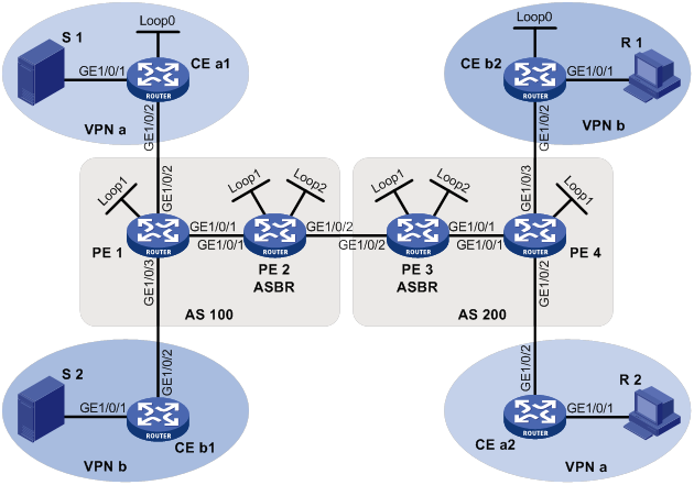
Table 20 Interface and IP address assignment
|
Device |
Interface |
IP address |
Device |
Interface |
IP address |
|
S 1 |
— |
10.11.5.2/24 |
R 1 |
— |
10.11.8.2/24 |
|
S 2 |
— |
10.11.6.2/24 |
R 2 |
— |
10.11.7.2/24 |
|
PE 1 |
GE1/0/1 |
10.10.1.1/24 |
PE 3 |
GE1/0/1 |
10.10.2.1/24 |
|
PE 1 |
GE1/0/2 |
10.11.1.1/24 |
PE 3 |
GE1/0/2 |
192.168.1.2/24 |
|
PE 1 |
GE1/0/3 |
10.11.2.1/24 |
PE 3 |
Loop1 |
1.1.1.3/32 |
|
PE 1 |
Loop1 |
1.1.1.1/32 |
PE 3 |
Loop2 |
22.22.22.22/32 |
|
PE 2 |
GE1/0/1 |
10.10.1.2/24 |
PE 4 |
GE1/0/1 |
10.10.2.2/24 |
|
PE 2 |
GE1/0/2 |
192.168.1.1/24 |
PE 4 |
GE1/0/2 |
10.11.3.1/24 |
|
PE 2 |
Loop1 |
1.1.1.2/32 |
PE 4 |
GE1/0/3 |
10.11.4.1/32 |
|
PE 2 |
Loop2 |
11.11.11.11/32 |
PE 4 |
Loop1 |
1.1.1.4/32 |
|
CE a1 |
GE1/0/1 |
10.11.5.1/24 |
CE b1 |
GE1/0/1 |
10.11.6.1/24 |
|
CE a1 |
GE1/0/2 |
10.11.1.2/24 |
CE b1 |
GE1/0/2 |
10.11.2.2/24 |
|
CE a1 |
Loop0 |
2.2.2.2/32 |
CE b2 |
GE1/0/1 |
10.11.8.1/24 |
|
CE a2 |
GE1/0/1 |
10.11.7.1/24 |
CE b2 |
GE1/0/2 |
10.11.4.2/24 |
|
CE a2 |
GE1/0/2 |
10.11.3.2/24 |
CE b2 |
Loop0 |
3.3.3.3/32 |
Configuration procedure
1. Configure PE 1:
# Configure a global router ID, and enable IP multicast routing on the public network.
<PE1> system-view
[PE1] router id 1.1.1.1
[PE1] multicast routing
[PE1-mrib] quit
# Configure an LSR ID, and enable LDP globally.
[PE1] mpls lsr-id 1.1.1.1
[PE1] mpls ldp
[PE1-ldp] quit
# Create a VPN instance named a, and configure an RD and route targets for the VPN instance.
[PE1] ip vpn-instance a
[PE1-vpn-instance-a] route-distinguisher 100:1
[PE1-vpn-instance-a] vpn-target 100:1 export-extcommunity
[PE1-vpn-instance-a] vpn-target 100:1 import-extcommunity
[PE1-vpn-instance-a] quit
# Enable IP multicast routing for VPN instance a.
[PE1] multicast routing vpn-instance a
[PE1-mrib-a] quit
# Create an MD for VPN instance a.
[PE1] multicast-domain vpn-instance a
# Create an MD IPv4 address family for VPN instance a.
[PE1-md-a] address-family ipv4
# Specify the default-group, the MD source interface, and the data-group range for VPN instance a.
[PE1-md-a-ipv4] default-group 239.1.1.1
[PE1-md-a-ipv4] source loopback 1
[PE1-md-a-ipv4] data-group 225.1.1.0 28
[PE1-md-a-ipv4] quit
[PE1-md-a] quit
# Create a VPN instance named b, and configure an RD and route targets for the VPN instance.
[PE1] ip vpn-instance b
[PE1-vpn-instance-b] route-distinguisher 200:1
[PE1-vpn-instance-b] vpn-target 200:1 export-extcommunity
[PE1-vpn-instance-b] vpn-target 200:1 import-extcommunity
[PE1-vpn-instance-b] quit
# Enable IP multicast routing for VPN instance b.
[PE1] multicast routing vpn-instance b
[PE1-mrib-b] quit
# Create an MD for VPN instance b.
[PE1] multicast-domain vpn-instance b
# Create an MD IPv4 address family for VPN instance b.
[PE1-md-b] address-family ipv4
# Specify the default-group, the MD source interface, and the data-group range for VPN instance b.
[PE1-md-b-ipv4] default-group 239.4.4.4
[PE1-md-b-ipv4] source loopback 1
[PE1-md-b-ipv4] data-group 225.4.4.0 28
[PE1-md-b-ipv4] quit
[PE1-md-b] quit
# Assign an IP address to GigabitEthernet 1/0/1.
[PE1] interface gigabitethernet 1/0/1
[PE1-GigabitEthernet1/0/1] ip address 10.10.1.1 24
# Enable PIM-SM, MPLS, and IPv4 LDP on GigabitEthernet 1/0/1.
[PE1-GigabitEthernet1/0/1] pim sm
[PE1-GigabitEthernet1/0/1] mpls enable
[PE1-GigabitEthernet1/0/1] mpls ldp enable
[PE1-GigabitEthernet1/0/1] quit
# Associate GigabitEthernet 1/0/2 with VPN instance a.
[PE1] interface gigabitethernet 1/0/2
[PE1-GigabitEthernet1/0/2] ip binding vpn-instance a
# Assign an IP address to GigabitEthernet 1/0/2, and enable PIM-SM on the interface.
[PE1-GigabitEthernet1/0/2] ip address 10.11.1.1 24
[PE1-GigabitEthernet1/0/2] pim sm
[PE1-GigabitEthernet1/0/2] quit
# Associate GigabitEthernet 1/0/3 with VPN instance b.
[PE1] interface gigabitethernet 1/0/3
[PE1-GigabitEthernet1/0/3] ip binding vpn-instance b
# Assign an IP address to GigabitEthernet 1/0/3, and enable PIM-SM on the interface.
[PE1-GigabitEthernet1/0/3] ip address 10.11.2.1 24
[PE1-GigabitEthernet1/0/3] pim sm
[PE1-GigabitEthernet1/0/3] quit
# Assign an IP address to Loopback 1, and enable PIM-SM on the interface.
[PE1] interface loopback 1
[PE1-LoopBack1] ip address 1.1.1.1 32
[PE1-LoopBack1] pim sm
[PE1-LoopBack1] quit
# Configure BGP.
[PE1] bgp 100
[PE1-bgp-default] group pe1-pe2 internal
[PE1-bgp-default] peer pe1-pe2 connect-interface loopback 1
[PE1-bgp-default] peer 1.1.1.2 group pe1-pe2
[PE1-bgp-default] group pe1-pe4 external
[PE1-bgp-default] peer pe1-pe4 as-number 200
[PE1-bgp-default] peer pe1-pe4 ebgp-max-hop 255
[PE1-bgp-default] peer pe1-pe4 connect-interface loopback 1
[PE1-bgp-default] peer 1.1.1.4 group pe1-pe4
[PE1–bgp-default] ip vpn-instance a
[PE1-bgp-default-a] address-family ipv4
[PE1-bgp-default-ipv4-a] import-route ospf 2
[PE1-bgp-default-ipv4-a] import-route direct
[PE1-bgp-default-ipv4-a] quit
[PE1-bgp-default-a] quit
[PE1–bgp-default] ip vpn-instance b
[PE1-bgp-default-b] address-family ipv4
[PE1-bgp-default-ipv4-b] import-route ospf 3
[PE1-bgp-default-ipv4-b] import-route direct
[PE1-bgp-default-ipv4-b] quit
[PE1-bgp-default-b] quit
[PE1–bgp-default] address-family ipv4
[PE1-bgp-default-ipv4] peer pe1-pe2 enable
[PE1-bgp-default-ipv4] peer pe1-pe2 label-route-capability
[PE1-bgp-default-ipv4] quit
[PE1–bgp-default] address-family vpnv4
[PE1–bgp-default-vpnv4] peer pe1-pe4 enable
[PE1–bgp-default-vpnv4] quit
[PE1–bgp-default] quit
# Configure OSPF.
[PE1] ospf 1
[PE1-ospf-1] area 0.0.0.0
[PE1-ospf-1-area-0.0.0.0] network 1.1.1.1 0.0.0.0
[PE1-ospf-1-area-0.0.0.0] network 10.10.1.0 0.0.0.255
[PE1-ospf-1-area-0.0.0.0] quit
[PE1-ospf-1] quit
[PE1] ospf 2 vpn-instance a
[PE1-ospf-2] import-route bgp
[PE1-ospf-2] area 0.0.0.0
[PE1-ospf-2-area-0.0.0.0] network 10.11.1.0 0.0.0.255
[PE1-ospf-2-area-0.0.0.0] quit
[PE1-ospf-2] quit
[PE1] ospf 3 vpn-instance b
[PE1-ospf-3] import-route bgp
[PE1-ospf-3] area 0.0.0.0
[PE1-ospf-3-area-0.0.0.0] network 10.11.2.0 0.0.0.255
[PE1-ospf-3-area-0.0.0.0] quit
[PE1-ospf-3] quit
2. Configure PE 2:
# Configure a global router ID, and enable IP multicast routing on the public network.
<PE2> system-view
[PE2] router id 1.1.1.2
[PE2] multicast routing
[PE2-mrib] quit
# Configure an LSR ID, and enable LDP globally.
[PE2] mpls lsr-id 1.1.1.2
[PE2] mpls ldp
[PE2-mpls-ldp] quit
# Assign an IP address to GigabitEthernet 1/0/1.
[PE2] interface gigabitethernet 1/0/1
[PE2-GigabitEthernet1/0/1] ip address 10.10.1.2 24
# Enable PIM-SM, MPLS, and IPv4 LDP on GigabitEthernet 1/0/1.
[PE2-GigabitEthernet1/0/1] pim sm
[PE2-GigabitEthernet1/0/1] mpls enable
[PE2-GigabitEthernet1/0/1] mpls ldp enable
[PE2-GigabitEthernet1/0/1] quit
# Assign an IP address to GigabitEthernet 1/0/2.
[PE2] interface gigabitethernet 1/0/2
[PE2-GigabitEthernet1/0/2] ip address 192.168.1.1 24
# Enable PIM-SM and MPLS on GigabitEthernet 1/0/2.
[PE2-GigabitEthernet1/0/2] pim sm
[PE2-GigabitEthernet1/0/2] mpls enable
[PE2-GigabitEthernet1/0/2] quit
# Assign an IP address to Loopback 1, and enable PIM-SM on the interface.
[PE2] interface loopback 1
[PE2-LoopBack1] ip address 1.1.1.2 32
[PE2-LoopBack1] pim sm
[PE2-LoopBack1] quit
# Assign an IP address to Loopback 2, and enable PIM-SM on the interface.
[PE2] interface loopback 2
[PE2-LoopBack2] ip address 11.11.11.11 32
[PE2-LoopBack2] pim sm
[PE2-LoopBack2] quit
# Configure Loopback 2 as a C-BSR and a C-RP.
[PE2] pim
[PE2-pim] c-bsr 11.11.11.11
[PE2-pim] c-rp 11.11.11.11
[PE2-pim] quit
# Configure GigabitEthernet 1/0/2 as a PIM-SM domain border.
[PE2] interface gigabitethernet 1/0/2
[PE2-GigabitEthernet1/0/2] pim bsr-boundary
[PE2-GigabitEthernet1/0/2] quit
# Establish an MSDP peering relationship.
[PE2] msdp
[PE2-msdp] encap-data-enable
[PE2-msdp] peer 1.1.1.3 connect-interface loopback 1
# Configure a static route.
[PE2] ip route-static 1.1.1.3 32 gigabitethernet 1/0/2 192.168.1.2
# Configure BGP.
[PE2] bgp 100
[PE2-bgp-default] group pe2-pe1 internal
[PE2-bgp-default] peer pe2-pe1 connect-interface loopback 1
[PE2-bgp-default] peer 1.1.1.1 group pe2-pe1
[PE2-bgp-default] group pe2-pe3 external
[PE2-bgp-default] peer pe2-pe3 as-number 200
[PE2-bgp-default] peer pe2-pe3 connect-interface loopback 1
[PE2-bgp-default] peer 1.1.1.3 group pe2-pe3
[PE2-bgp-default] address-family ipv4
[PE2-bgp-default-ipv4] peer pe2-pe1 enable
[PE2-bgp-default-ipv4] peer pe2-pe1 route-policy map2 export
[PE2-bgp-default-ipv4] peer pe2-pe1 label-route-capability
[PE2-bgp-default-ipv4] peer pe2-pe3 enable
[PE2-bgp-default-ipv4] peer pe2-pe3 route-policy map1 export
[PE2-bgp-default-ipv4] peer pe2-pe3 label-route-capability
[PE2-bgp-default-ipv4] import-route ospf 1
[PE2-bgp-default-ipv4] quit
[PE2–bgp-default] quit
# Configure OSPF.
[PE2] ospf 1
[PE2-ospf-1] area 0.0.0.0
[PE2-ospf-1-area-0.0.0.0] network 1.1.1.2 0.0.0.0
[PE2-ospf-1-area-0.0.0.0] network 11.11.11.11 0.0.0.0
[PE2-ospf-1-area-0.0.0.0] network 10.10.1.0 0.0.0.255
[PE2-ospf-1-area-0.0.0.0] quit
[PE2-ospf-1] quit
3. Configure PE 3:
# Configure a global router ID, and enable IP multicast routing on the public network.
<PE3> system-view
[PE3] router id 1.1.1.3
[PE3] multicast routing
[PE3-mrib] quit
# Configure an LSR ID, and enable LDP globally.
[PE3] mpls lsr-id 1.1.1.3
[PE3] mpls ldp
[PE3-ldp] quit
# Assign an IP address to GigabitEthernet 1/0/1.
[PE3] interface gigabitethernet 1/0/1
[PE3-GigabitEthernet1/0/1] ip address 10.10.2.1 24
# Enable PIM-SM, MPLS, and IPv4 LDP on GigabitEthernet 1/0/1.
[PE3-GigabitEthernet1/0/1] pim sm
[PE3-GigabitEthernet1/0/1] mpls enable
[PE3-GigabitEthernet1/0/1] mpls ldp enable
[PE3-GigabitEthernet1/0/1] quit
# Assign an IP address to GigabitEthernet 1/0/2.
[PE3] interface gigabitethernet 1/0/2
[PE3-GigabitEthernet1/0/2] ip address 192.168.1.2 24
# Enable PIM-SM and MPLS on GigabitEthernet 1/0/2.
[PE3-GigabitEthernet1/0/2] pim sm
[PE3-GigabitEthernet1/0/2] mpls enable
[PE3-GigabitEthernet1/0/2] quit
# Assign an IP address to Loopback 1, and enable PIM-SM on the interface.
[PE3] interface loopback 1
[PE3-LoopBack1] ip address 1.1.1.3 32
[PE3-LoopBack1] pim sm
[PE3-LoopBack1] quit
# Assign an IP address to Loopback 2, and enable PIM-SM on the interface.
[PE3] interface loopback 2
[PE3-LoopBack2] ip address 22.22.22.22 32
[PE3-LoopBack2] pim sm
[PE3-LoopBack2] quit
# Configure Loopback 2 as a C-BSR and a C-RP.
[PE3] pim
[PE3-pim] c-bsr 22.22.22.22
[PE3-pim] c-rp 22.22.22.22
[PE3-pim] quit
# Configure GigabitEthernet 1/0/2 as a PIM-SM domain border.
[PE3] interface gigabitethernet 1/0/2
[PE3-GigabitEthernet1/0/2] pim bsr-boundary
[PE3-GigabitEthernet1/0/2] quit
# Establish an MSDP peering relationship.
[PE3] msdp
[PE3-msdp] encap-data-enable
[PE3-msdp] peer 1.1.1.2 connect-interface loopback 1
# Configure a static route.
[PE3] ip route-static 1.1.1.2 32 gigabitethernet 1/0/2 192.168.1.1
# Configure BGP.
[PE3] bgp 200
[PE3-bgp-default] group pe3-pe4 internal
[PE3-bgp-default] peer pe3-pe4 connect-interface loopback 1
[PE3-bgp-default] peer 1.1.1.4 group pe3-pe4
[PE3-bgp-default] group pe3-pe2 external
[PE3-bgp-default] peer pe3-pe2 as-number 100
[PE3-bgp-default] peer pe3-pe2 connect-interface loopback 1
[PE3-bgp-default] peer 1.1.1.2 group pe3-pe2
[PE3-bgp-default] address-family ipv4
[PE3-bgp-default-ipv4] peer pe3-pe4 enable
[PE3-bgp-default-ipv4] peer pe3-pe4 route-policy map2 export
[PE3-bgp-default-ipv4] peer pe3-pe4 label-route-capability
[PE3-bgp-default-ipv4] peer pe3-pe2 enable
[PE3-bgp-default-ipv4] peer pe3-pe2 route-policy map1 export
[PE3-bgp-default-ipv4] peer pe3-pe2 label-route-capability
[PE3-bgp-default-ipv4] import-route ospf 1
[PE3-bgp-default-ipv4] quit
[PE3–bgp-default] quit
# Configure OSPF.
[PE3] ospf 1
[PE3-ospf-1] area 0.0.0.0
[PE3-ospf-1-area-0.0.0.0] network 1.1.1.3 0.0.0.0
[PE3-ospf-1-area-0.0.0.0] network 22.22.22.22 0.0.0.0
[PE3-ospf-1-area-0.0.0.0] network 10.10.2.0 0.0.0.255
[PE3-ospf-1-area-0.0.0.0] quit
[PE3-ospf-1] quit
4. Configure PE 4:
# Configure a global router ID, and enable IP multicast routing on the public network.
<PE4> system-view
[PE4] router id 1.1.1.4
[PE4] multicast routing
[PE4-mrib] quit
# Configure an LSR ID, and enable LDP globally.
[PE4] mpls lsr-id 1.1.1.4
[PE4] mpls ldp
[PE4-ldp] quit
# Create a VPN instance named a, and configure an RD and route targets for the VPN instance.
[PE4] ip vpn-instance a
[PE4-vpn-instance-a] route-distinguisher 100:1
[PE4-vpn-instance-a] vpn-target 100:1 export-extcommunity
[PE4-vpn-instance-a] vpn-target 100:1 import-extcommunity
[PE4-vpn-instance-a] quit
# Enable IP multicast routing for VPN instance a.
[PE4] multicast routing vpn-instance a
[PE4-mrib-a] quit
# Create an MD for VPN instance a.
[PE4] multicast-domain vpn-instance a
# Create an MD IPv4 address family for VPN instance a.
[PE4-md-a] address-family ipv4
# Specify the default-group, the MD source interface, and the data-group range for VPN instance a.
[PE4-md-a-ipv4] default-group 239.1.1.1
[PE4-md-a-ipv4] source loopback 1
[PE4-md-a-ipv4] data-group 225.1.1.0 28
[PE4-md-a-ipv4] quit
[PE4-md-a] quit
# Create a VPN instance named b, and configure an RD and route targets for the VPN instance.
[PE4] ip vpn-instance b
[PE4-vpn-instance-b] route-distinguisher 200:1
[PE4-vpn-instance-b] vpn-target 200:1 export-extcommunity
[PE4-vpn-instance-b] vpn-target 200:1 import-extcommunity
[PE4-vpn-instance-b] quit
# Enable IP multicast routing for VPN instance b.
[PE4] multicast routing vpn-instance b
[PE4-mrib-b] quit
# Create an MD for VPN instance b.
[PE4] multicast-domain vpn-instance b
# Create an MD IPv4 address family for VPN instance b.
[PE4-md-b] address-family ipv4
# Specify the default-group, MD source interface, and the data-group range for VPN instance b.
[PE4-md-b-ipv4] default-group 239.4.4.4
[PE4-md-b-ipv4] source loopback 1
[PE4-md-b-ipv4] data-group 225.4.4.0 28
[PE4-md-b-ipv4] quit
[PE4-md-b] quit
# Assign an IP address to GigabitEthernet 1/0/1.
[PE4] interface gigabitethernet 1/0/1
[PE4-GigabitEthernet1/0/1] ip address 10.10.2.2 24
# Enable PIM-SM, MPLS, and IPv4 LDP on GigabitEthernet 1/0/1.
[PE4-GigabitEthernet1/0/1] pim sm
[PE4-GigabitEthernet1/0/1] mpls enable
[PE4-GigabitEthernet1/0/1] mpls ldp enable
[PE4-GigabitEthernet1/0/1] quit
# Associate GigabitEthernet 1/0/2 with VPN instance a.
[PE4] interface gigabitethernet 1/0/2
[PE4-GigabitEthernet1/0/2] ip binding vpn-instance a
# Assign an IP address to GigabitEthernet 1/0/2, and enable PIM-SM on the interface.
[PE4-GigabitEthernet1/0/2] ip address 10.11.3.1 24
[PE4-GigabitEthernet1/0/2] pim sm
[PE4-GigabitEthernet1/0/2] quit
# Associate GigabitEthernet 1/0/3 with VPN instance b.
[PE4] interface gigabitethernet 1/0/3
[PE4-GigabitEthernet1/0/3] ip binding vpn-instance b
# Assign an IP address to GigabitEthernet 1/0/3, and enable PIM-SM on the interface.
[PE4-GigabitEthernet1/0/3] ip address 10.11.4.1 24
[PE4-GigabitEthernet1/0/3] pim sm
[PE4-GigabitEthernet1/0/3] quit
# Assign an IP address to Loopback 1, and enable PIM-SM on the interface.
[PE4] interface loopback 1
[PE4-LoopBack1] ip address 1.1.1.4 32
[PE4-LoopBack1] pim sm
[PE4-LoopBack1] quit
# Configure BGP.
[PE4] bgp 200
[PE4-bgp-default] group pe4-pe3 internal
[PE4-bgp-default] peer pe4-pe3 connect-interface loopback 1
[PE4-bgp-default] peer 1.1.1.3 group pe4-pe3
[PE4-bgp-default] group pe4-pe1 external
[PE4-bgp-default] peer pe4-pe1 as-number 100
[PE4-bgp-default] peer pe4-pe1 ebgp-max-hop 255
[PE4-bgp-default] peer pe4-pe1 connect-interface loopback 1
[PE4-bgp-default] peer 1.1.1.1 group pe4-pe1
[PE4–bgp-default] ip vpn-instance a
[PE4-bgp-default-a] address-family ipv4
[PE4-bgp-default-ipv4-a] import-route ospf 2
[PE4-bgp-default-ipv4-a] import-route direct
[PE4-bgp-default-ipv4-a] quit
[PE4-bgp-default-a] quit
[PE4–bgp-default] ip vpn-instance b
[PE4-bgp-default-b] address-family ipv4
[PE4-bgp-default-ipv4-b] import-route ospf 3
[PE4-bgp-default-ipv4-b] import-route direct
[PE4-bgp-default-ipv4-b] quit
[PE4-bgp-default-b] quit
[PE4–bgp-default] address-family ipv4
[PE4-bgp-default-ipv4] peer pe4-pe3 enable
[PE4-bgp-default-ipv4] peer pe4-pe3 label-route-capability
[PE4-bgp-default-ipv4] quit
[PE4–bgp-default] address-family vpnv4
[PE4–bgp-default-vpnv4] peer pe4-pe1 enable
[PE4–bgp-default-vpnv4] quit
[PE4–bgp-default] quit
# Configure OSPF.
[PE4] ospf 1
[PE4-ospf-1] area 0.0.0.0
[PE4-ospf-1-area-0.0.0.0] network 1.1.1.4 0.0.0.0
[PE4-ospf-1-area-0.0.0.0] network 10.10.2.0 0.0.0.255
[PE4-ospf-1-area-0.0.0.0] quit
[PE4-ospf-1] quit
[PE4] ospf 2 vpn-instance a
[PE4-ospf-2] import-route bgp
[PE4-ospf-2] area 0.0.0.0
[PE4-ospf-2-area-0.0.0.0] network 10.11.3.0 0.0.0.255
[PE4-ospf-2-area-0.0.0.0] quit
[PE4-ospf-2] quit
[PE4] ospf 3 vpn-instance b
[PE4-ospf-3] import-route bgp
[PE4-ospf-3] area 0.0.0.0
[PE4-ospf-3-area-0.0.0.0] network 10.11.4.0 0.0.0.255
[PE4-ospf-3-area-0.0.0.0] quit
[PE4-ospf-3] quit
5. Configure CE a1:
# Enable IP multicast routing.
<CEa1> system-view
[CEa1] multicast routing
[CEa1-mrib] quit
# Assign an IP address to GigabitEthernet 1/0/1, and enable PIM-SM on the interface.
[CEa1] interface gigabitethernet 1/0/1
[CEa1-GigabitEthernet1/0/1] ip address 10.11.5.1 24
[CEa1-GigabitEthernet1/0/1] pim sm
[CEa1-GigabitEthernet1/0/1] quit
# Assign an IP address to GigabitEthernet 1/0/2, and enable PIM-SM on the interface.
[CEa1] interface gigabitethernet 1/0/2
[CEa1-GigabitEthernet1/0/2] ip address 10.11.1.2 24
[CEa1-GigabitEthernet1/0/2] pim sm
[CEa1-GigabitEthernet1/0/2] quit
# Assign an IP address to Loopback 1, and enable PIM-SM on the interface.
[CEa1] interface loopback 1
[CEa1-LoopBack1] ip address 2.2.2.2 32
[CEa1-LoopBack1] pim sm
[CEa1-LoopBack1] quit
# Configure Loopback 1 as a C-BSR and a C-RP.
[CEa1] pim
[CEa1-pim] c-bsr 2.2.2.2
[CEa1-pim] c-rp 2.2.2.2 1
[CEa1-pim] quit
# Configure OSPF.
[CEa1] ospf 1
[CEa1-ospf-1] area 0.0.0.0
[CEa1-ospf-1-area-0.0.0.0] network 2.2.2.2 0.0.0.0
[CEa1-ospf-1-area-0.0.0.0] network 10.11.1.0 0.0.0.255
[CEa1-ospf-1-area-0.0.0.0] network 10.11.5.0 0.0.0.255
[CEa1-ospf-1-area-0.0.0.0] quit
[CEa1-ospf-1] quit
6. Configure CE b1:
# Enable IP multicast routing.
<CEb1> system-view
[CEb1] multicast routing
[CEb1-mrib] quit
# Assign an IP address to GigabitEthernet 1/0/1, and enable PIM-SM on the interface.
[CEb1] interface gigabitethernet 1/0/1
[CEb1-GigabitEthernet1/0/1] ip address 10.11.6.1 24
[CEb1-GigabitEthernet1/0/1] pim sm
[CEb1-GigabitEthernet1/0/1] quit
# Assign an IP address to GigabitEthernet 1/0/2, and enable PIM-SM on the interface.
[CEb1] interface gigabitethernet 1/0/2
[CEb1-GigabitEthernet1/0/2] ip address 10.11.2.2 24
[CEb1-GigabitEthernet1/0/2] pim sm
[CEb1-GigabitEthernet1/0/2] quit
# Configure OSPF.
[CEb1] ospf 1
[CEb1-ospf-1] area 0.0.0.0
[CEb1-ospf-1-area-0.0.0.0] network 10.11.2.0 0.0.0.255
[CEb1-ospf-1-area-0.0.0.0] network 10.11.6.0 0.0.0.255
[CEb1-ospf-1-area-0.0.0.0] quit
[CEb1-ospf-1] quit
7. Configure CE a2:
# Enable IP multicast routing.
<CEa2> system-view
[CEa2] multicast routing
[CEa2-mrib] quit
# Assign an IP address to GigabitEthernet 1/0/1, and enable IGMP on the interface.
[CEa2] interface gigabitethernet 1/0/1
[CEa2-GigabitEthernet1/0/1] ip address 10.11.7.1 24
[CEa2-GigabitEthernet1/0/1] igmp enable
[CEa2-GigabitEthernet1/0/1] quit
# Assign an IP address to GigabitEthernet 1/0/2, and enable PIM-SM on the interface.
[CEa2] interface gigabitethernet 1/0/2
[CEa2-GigabitEthernet1/0/2] ip address 10.11.3.2 24
[CEa2-GigabitEthernet1/0/2] pim sm
[CEa2-GigabitEthernet1/0/2] quit
# Configure OSPF.
[CEa2] ospf 1
[CEa2-ospf-1] area 0.0.0.0
[CEa2-ospf-1-area-0.0.0.0] network 10.11.3.0 0.0.0.255
[CEa2-ospf-1-area-0.0.0.0] network 10.11.7.0 0.0.0.255
[CEa2-ospf-1-area-0.0.0.0] quit
[CEa2-ospf-1] quit
8. Configure CE b2:
# Enable IP multicast routing.
<CEb2> system-view
[CEb2] multicast routing
[CEb2-mrib] quit
# Assign an IP address to GigabitEthernet 1/0/1, and enable IGMP on the interface.
[CEb2] interface gigabitethernet 1/0/1
[CEb2-GigabitEthernet1/0/1] ip address 10.11.8.1 24
[CEb2-GigabitEthernet1/0/1] igmp enable
[CEb2-GigabitEthernet1/0/1] quit
# Assign an IP address to GigabitEthernet 1/0/2, and enable PIM-SM on the interface.
[CEb2] interface gigabitethernet 1/0/2
[CEb2-GigabitEthernet1/0/2] ip address 10.11.4.2 24
[CEb2-GigabitEthernet1/0/2] pim sm
[CEb2-GigabitEthernet1/0/2] quit
# Assign an IP address to Loopback 1, and enable PIM-SM on the interface.
[CEb2] interface loopback 1
[CEb2-LoopBack1] ip address 3.3.3.3 32
[CEb2-LoopBack1] pim sm
[CEb2-LoopBack1] quit
# Configure Loopback 1 as a C-BSR and a C-RP.
[CEb2] pim
[CEb2-pim] c-bsr 3.3.3.3
[CEb2-pim] c-rp 3.3.3.3
[CEb2-pim] quit
# Configure OSPF.
[CEb2] ospf 1
[CEb2-ospf-1] area 0.0.0.0
[CEb2-ospf-1-area-0.0.0.0] network 3.3.3.3 0.0.0.0
[CEb2-ospf-1-area-0.0.0.0] network 10.11.4.0 0.0.0.255
[CEb2-ospf-1-area-0.0.0.0] network 10.11.8.0 0.0.0.255
[CEb2-ospf-1-area-0.0.0.0] quit
[CEb2-ospf-1] quit
Verifying the configuration
# Display information about the local default-group for IPv4 multicast transmission in each VPN instance on PE 1.
[PE1] display multicast-domain default-group local
MD local default-group information:
Group address Source address Interface VPN instance
239.1.1.1 1.1.1.1 MTunnel0 a
239.4.4.4 1.1.1.1 MTunnel1 b
# Display information about the local default-group for IPv4 multicast transmission in each VPN instance on PE 4.
[PE4] display multicast-domain default-group local
MD local default-group information:
Group address Source address Interface VPN instance
239.1.1.1 1.1.1.4 MTunnel0 a
239.4.4.4 1.1.1.4 MTunnel1 b
MD VPN inter-AS option B configuration example
Network requirements
As shown in Figure 74, configure MD VPN inter-AS option B to meet the following requirements:
|
Item |
Network requirements |
|
Multicast sources and receivers |
· In VPN instance a, S 1 is a multicast source, and R 2 is a receiver. · In VPN instance b, S 2 is a multicast source, and R 1 is a receiver. · For VPN instance a, the default-group is 232.1.1.1, and the data-group range is 232.2.2.0 to 232.2.2.15. They are in the SSM group range. · For VPN instance b, the default-group is 232.3.3.3, and the data-group range is 232.4.4.0 to 232.4.4.15. They are in the SSM group range. |
|
VPN instances to which PE interfaces belong |
· PE 1: GigabitEthernet 1/0/2 belongs to VPN instance a. GigabitEthernet 1/0/3 belongs to VPN instance b. GigabitEthernet 1/0/1 and Loopback 1 belong to the public network instance. · PE 2: GigabitEthernet 1/0/1, GigabitEthernet 1/0/2, and Loopback 1 belong to the public network instance. · PE 3: GigabitEthernet 1/0/1, GigabitEthernet 1/0/2, and Loopback 1 belong to the public network instance. · PE 4: GigabitEthernet 1/0/2 belongs to VPN instance a. GigabitEthernet 1/0/3 belongs to VPN instance b. GigabitEthernet 1/0/1 and Loopback 1 belong to the public network instance. |
|
Unicast routing protocols and MPLS |
· Configure OSPF in AS 100 and AS 200, and configure OSPF between the PEs and CEs. · Establish IBGP peer connections between PE 1, PE 2, PE 3, and PE 4 on their respective Loopback 1. · Establish EBGP peer connections between GigabitEthernet 1/0/2 on PE 2 and PE 3. · Configure BGP MDT peer connections between PE 1, PE 2, PE 3, and PE 4 on their respective Loopback 1 and between PE 2 and PE 3 on their respective GigabitEthernet 1/0/2. · Configure MPLS in AS 100 and AS 200. |
|
IP multicast routing |
· Enable IP multicast routing on P 1 and P 2. · Enable IP multicast routing for the public network on PE 1, PE 2, PE 3, and PE 4. · Enable IP multicast routing for VPN instance a on PE 1 and PE 4. · Enable IP multicast routing for VPN instance b on PE 1 and PE 4. · Enable IP multicast routing on CE a1, CE a2, CE b1, and CE b2. |
|
IGMPv2 |
· Enable IGMPv2 on GigabitEthernet 1/0/1 of CE a2. · Enable IGMPv2 on GigabitEthernet 1/0/1 of CE b2. |
|
PIM |
Enable PIM-SSM on the public network and PIM-SM for VPN instances a and b: · Enable PIM-SM on all interfaces of P 1 and P 2. · Enable PIM-SM on all public network interfaces of PE 2 and PE 3. · Enable PIM-SM on all public and private network interfaces of PE 1 and PE 4. · Enable PIM-SM on all interfaces that do not have attached receiver hosts on CE a1, CE a2, CE b1, and CE b2. · Configure GigabitEthernet 1/0/2 of CE a1 as a C-BSR and a C-RP for VPN instance a to provide services for all multicast groups. · Configure GigabitEthernet 1/0/2 of CE a1 as a C-BSR and a C-RP for VPN instance b to provide services for all multicast groups. |
|
RPF vector |
Enable the RPF vector feature on PE 1 and PE 4. |
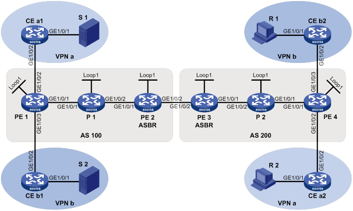
Table 21 Interface and IP address assignment
|
Device |
Interface |
IP address |
Device |
Interface |
IP address |
|
— |
— |
||||
|
— |
— |
||||
|
PE 1 |
PE 3 |
||||
|
PE 1 |
PE 3 |
||||
|
PE 1 |
|||||
|
PE 4 |
|||||
|
PE 2 |
PE 4 |
||||
|
PE 2 |
PE 4 |
||||
|
P 1 |
P 2 |
||||
|
P 1 |
P 2 |
||||
|
CE a1 |
CE b1 |
||||
|
CE a2 |
CE b2 |
Configuration procedure
1. Configure PE 1:
# Configure a global router ID, and enable IP multicast routing on the public network.
[PE1] router id 1.1.1.1
[PE1] multicast routing
[PE1-mrib] quit
# Configure an LSR ID, and enable LDP globally.
[PE1] mpls ldp
[PE1-ldp] quit
# Create a VPN instance named a, and configure the RD and route targets for the VPN instance.
[PE1-vpn-instance-sa] route-distinguisher 100:1
[PE1-vpn-instance-a] vpn-target 100:1 export-extcommunity
[PE1-vpn-instance-a] vpn-target 100:1 import-extcommunity
[PE1-vpn-instance-a] quit
# Enable IP multicast routing and RPF vector for VPN instance a.
[PE1] multicast routing vpn-instance a
[PE1-mrib-a] rpf proxy vector
[PE1-mrib-a] quit
# Create an MD for VPN instance a.
[PE1] multicast-domain vpn-instance a
# Create an MD IPv4 address family for VPN instance a.
[PE1-md-a] address-family ipv4
# Specify the default-group, the MD source interface, and the data-group range for VPN instance a.
[PE1-md-a-ipv4] default-group 232.1.1.1
[PE1-md-a-ipv4] source loopback 1
[PE1-md-a-ipv4] data-group 232.2.2.0 28
[PE1-md-a-ipv4] quit
[PE1-md-a] quit
# Create a VPN instance named b, and configure the RD and route targets for the VPN instance.
[PE1-vpn-instance-b] route-distinguisher 200:1
[PE1-vpn-instance-b] vpn-target 200:1 export-extcommunity
[PE1-vpn-instance-b] vpn-target 200:1 import-extcommunity
[PE1-vpn-instance-b] quit
# Enable IP multicast routing and RPF vector for VPN instance b.
[PE1] multicast routing vpn-instance b
[PE1-mrib-b] rpf proxy vector
[PE1-mrib-b] quit
# Create an MD for VPN instance b.
[PE1] multicast-domain vpn-instance b
# Create an MD IPv4 address family for VPN instance b.
[PE1-md-b] address-family ipv4
# Specify the default-group, the MD source interface, and the data-group range for VPN instance b.
[PE1-md-b-ipv4] default-group 232.3.3.3
[PE1-md-b-ivp4] source loopback 1
[PE1-md-b-ipv4] data-group 232.4.4.0 28
[PE1-md-b-ipv4] quit
[PE1-md-b] quit
# Assign an IP address to GigabitEthernet 1/0/1.
[PE1] interface gigabitethernet 1/0/1
[PE1-GigabitEthernet1/0/1] ip address 10.1.1.1 24
# Enable PIM-SM, MPLS, and IPv4 LDP on GigabitEthernet 1/0/1.
[PE1-GigabitEthernet1/0/1] pim sm
[PE1-GigabitEthernet1/0/1] mpls enable
[PE1-GigabitEthernet1/0/1] mpls ldp enable
[PE1-GigabitEthernet1/0/1] quit
# Associate GigabitEthernet 1/0/2 with VPN instance a.
[PE1] interface gigabitethernet 1/0/2
[PE1-GigabitEthernet1/0/2] ip binding vpn-instance a
# Assign an IP address to GigabitEthernet 1/0/2, and enable PIM-SM on the interface.
[PE1-GigabitEthernet1/0/2] ip address 11.1.1.1 24
[PE1-GigabitEthernet1/0/2] pim sm
[PE1-GigabitEthernet1/0/2] quit
# Associate GigabitEthernet 1/0/3 with VPN instance b.
[PE1] interface gigabitethernet 1/0/3
[PE1-GigabitEthernet1/0/3] ip binding vpn-instance b
# Assign an IP address to GigabitEthernet 1/0/3, and enable PIM-SM on the interface.
[PE1-GigabitEthernet1/0/3] ip address 11.2.1.1 24
[PE1-GigabitEthernet1/0/3] pim sm
[PE1-GigabitEthernet1/0/3] quit
# Assign an IP address to Loopback 1, and enable PIM-SM on the interface.
[PE1-LoopBack1] ip address 1.1.1.1 32
[PE1-LoopBack1] pim sm
[PE1-LoopBack1] quit
[PE1-bgp-default] peer 2.2.2.2 as-number 100
[PE1-bgp-default] peer 2.2.2.2 connect-interface loopback 1
[PE1–bgp-default] ip vpn-instance a
[PE1-bgp-default-a] address-family ipv4
[PE1-bgp-default-ipv4-a] import-route ospf 2
[PE1-bgp-default-ipv4-a] import-route direct
[PE1-bgp-default-ipv4-a] quit
[PE1-bgp-default-a] quit
[PE1–bgp-default] ip vpn-instance b
[PE1-bgp-default-b] address-family ipv4
[PE1-bgp-default-ipv4-b] import-route ospf 3
[PE1-bgp-default-ipv4-b] import-route direct
[PE1-bgp-default-ipv4-b] quit
[PE1-bgp-default-b] quit
[PE1–bgp-default] address-family vpnv4
[PE1–bgp-default-vpnv4] peer 2.2.2.2 enable
[PE1–bgp-default-vpnv4] quit
[PE1-bgp-default] address-family ipv4 mdt
[PE1-bgp-default-mdt] peer 2.2.2.2 enable
[PE1-bgp-default-mdt] quit
[PE1–bgp-default] quit
[PE1-ospf-1] area 0.0.0.0
[PE1-ospf-1-area-0.0.0.0] network 1.1.1.1 0.0.0.0
[PE1-ospf-1-area-0.0.0.0] network 10.1.1.0 0.0.0.255
[PE1-ospf-1-area-0.0.0.0] quit
[PE1-ospf-1] quit
# Configure OSPF.
[PE1] ospf 2 vpn-instance a
[PE1-ospf-2] area 0.0.0.0
[PE1-ospf-2-area-0.0.0.0] network 11.1.1.0 0.0.0.255
[PE1-ospf-2-area-0.0.0.0] quit
[PE1-ospf-2] quit
[PE1] ospf 3 vpn-instance b
[PE1-ospf-3] area 0.0.0.0
[PE1-ospf-3-area-0.0.0.0] network 11.2.1.0 0.0.0.255
[PE1-ospf-3-area-0.0.0.0] quit
[PE1-ospf-3] quit
# Configure a global router ID, and enable IP multicast routing on the public network.
[PE2] router id 2.2.2.2
[PE2] multicast routing
[PE2-mrib] quit
# Configure an LSR ID, and enable LDP globally.
[PE2] mpls ldp
[PE2-ldp] quit
# Assign an IP address to GigabitEthernet 1/0/1.
[PE2] interface gigabitethernet 1/0/1
[PE2-GigabitEthernet1/0/1] ip address 10.2.1.2 24
# Enable PIM-SM, MPLS, and IPv4 LDP on GigabitEthernet 1/0/1.
[PE2-GigabitEthernet1/0/1] pim sm
[PE2-GigabitEthernet1/0/1] mpls enable
[PE2-GigabitEthernet1/0/1] mpls ldp enable
[PE2-GigabitEthernet1/0/1] quit
# Assign an IP address to GigabitEthernet 1/0/2.
[PE2] interface gigabitethernet 1/0/2
[PE2-GigabitEthernet1/0/2] ip address 10.3.1.1 24
# Enable PIM-SM and MPLS on GigabitEthernet 1/0/2.
[PE2-GigabitEthernet1/0/2] pim sm
[PE2-GigabitEthernet1/0/2] mpls enable
[PE2-GigabitEthernet1/0/2] quit
# Assign an IP address to Loopback 1, and enable PIM-SM on the interface.
[PE2-LoopBack1] ip address 2.2.2.2 32
[PE2-LoopBack1] pim sm
[PE2-LoopBack1] quit
[PE2-bgp-default] group 1.1.1.1 as-number 100
[PE2-bgp-default] peer 1.1.1.1 connect-interface loopback 1
[PE2-bgp-default] peer 10.3.1.2 as-number 200
[PE2-bgp-default] address-family vpnv4
[PE2-bgp-default-vpnv4] undo policy vpn-target
[PE2-bgp-default-vpnv4] peer 1.1.1.1 enable
[PE2-bgp-default-vpnv4] peer 10.3.1.2 enable
[PE2-bgp-default-vpnv4] quit
[PE2-bgp-default] address-family ipv4 mdt
[PE2-bgp-default-mdt] peer 1.1.1.1 enable
[PE2-bgp-default-mdt] peer 10.3.1.2 enable
[PE2-bgp-default-mdt] quit
[PE2–bgp-default] quit
[PE2-ospf-1] area 0.0.0.0
[PE2-ospf-1-area-0.0.0.0] network 2.2.2.2 0.0.0.0
[PE2-ospf-1-area-0.0.0.0] network 10.2.1.0 0.0.0.255
[PE2-ospf-1-area-0.0.0.0] quit
[PE2-ospf-1] quit
# Configure a global router ID, and enable IP multicast routing on the public network.
[PE3] router id 3.3.3.3
[PE3] multicast routing
[PE3-mrib] quit
# Configure an LSR ID, and enable LDP globally.
[PE3] mpls ldp
[PE3-ldp] quit
# Assign an IP address to GigabitEthernet 1/0/1.
[PE3] interface gigabitethernet 1/0/1
[PE3-GigabitEthernet1/0/1] ip address 10.4.1.1 24
# Enable PIM-SM, MPLS, and IPv4 LDP on GigabitEthernet 1/0/1.
[PE3-GigabitEthernet1/0/1] pim sm
[PE3-GigabitEthernet1/0/1] mpls enable
[PE3-GigabitEthernet1/0/1] mpls ldp enable
[PE3-GigabitEthernet1/0/1] quit
# Assign an IP address to GigabitEthernet 1/0/2.
[PE3] interface gigabitethernet 1/0/2
[PE3-GigabitEthernet1/0/2] ip address 10.3.1.2 24
# Enable PIM-SM and MPLS on GigabitEthernet 1/0/2.
[PE3-GigabitEthernet1/0/2] pim sm
[PE3-GigabitEthernet1/0/2] mpls enable
[PE3-GigabitEthernet1/0/2] quit
# Assign an IP address to Loopback 1, and enable PIM-SM on the interface.
[PE3-LoopBack1] ip address 3.3.3.3 32
[PE3-LoopBack1] pim sm
[PE3-LoopBack1] quit
[PE3-bgp-default] group 4.4.4.4 as-number 200
[PE3-bgp-default] peer 4.4.4.4 connect-interface loopback 1
[PE3-bgp-default] peer 10.3.1.1 as-number 100
[PE3-bgp-default] address-family vpnv4
[PE3-bgp-default-vpnv4] undo policy vpn-target
[PE3-bgp-default-vpnv4] peer 4.4.4.4 enable
[PE3-bgp-default-vpnv4] peer 10.3.1.1 enable
[PE3-bgp-default-vpnv4] quit
[PE3-bgp-default] address-family ipv4 mdt
[PE3-bgp-default-mdt] peer 4.4.4.4 enable
[PE3-bgp-default-mdt] peer 10.3.1.1 enable
[PE3-bgp-default-mdt] quit
[PE3–bgp-default] quit
[PE3-ospf-1] area 0.0.0.0
[PE3-ospf-1-area-0.0.0.0] network 3.3.3.3 0.0.0.0
[PE3-ospf-1-area-0.0.0.0] network 10.4.1.0 0.0.0.255
[PE3-ospf-1-area-0.0.0.0] quit
[PE3-ospf-1] quit
# Configure a global router ID, and enable IP multicast routing on the public network.
[PE4] router id 4.4.4.4
[PE4] multicast routing
[PE4-mrib] quit
# Configure an LSR ID, and enable LDP globally.
[PE4] mpls ldp
[PE4-ldp] quit
# Create a VPN instance named a, and configure the RD and route targets for the VPN instance.
[PE4-vpn-instance-a] route-distinguisher 100:1
[PE4-vpn-instance-a] vpn-target 100:1 export-extcommunity
[PE4-vpn-instance-a] vpn-target 100:1 import-extcommunity
[PE4-vpn-instance-a] quit
# Enable IP multicast routing and RPF vector for VPN instance a.
[PE4] multicast routing vpn-instance a
[PE4-mrib-a] rpf proxy vector
[PE4-mrib-a] quit
# Create an MD for VPN instance a.
[PE4] multicast-domain vpn-instance a
# Create an MD IPv4 address family for VPN instance a.
[PE4-md-a] address-family ipv4
# Specify the default-group, the MD source interface, and the data-group range for VPN instance a.
[PE4-md-a-ipv4] default-group 232.1.1.1
[PE4-md-a-ipv4] source loopback 1
[PE4-md-a-ipv4] data-group 232.2.2.0 28
[PE4-md-a-ipv4] quit
[PE4-md-a] quit
# Create a VPN instance named b, and configure the RD and route targets for the VPN instance.
[PE4-vpn-instance-b] route-distinguisher 200:1
[PE4-vpn-instance-b] vpn-target 200:1 export-extcommunity
[PE4-vpn-instance-b] vpn-target 200:1 import-extcommunity
[PE4-vpn-instance-b] quit
# Enable IP multicast routing and RPF vector for VPN instance b.
[PE4] multicast routing vpn-instance b
[PE4-mrib-b] rpf proxy vector
[PE4-mrib-b] quit
# Create an MD for VPN instance b,.
[PE4] multicast-domain vpn-instance b
# Create an MD IPv4 address family for VPN instance b.
[PE4-md-b] address-family ipv4
# Specify the default-group, the MD source interface, and the data-group range for VPN instance b.
[PE4-md-b-ipv4] default-group 232.3.3.3
[PE4-md-b-ipv4] source loopback 1
[PE4-md-b-ipv4] data-group 232.4.4.0 28
[PE4-md-b-ipv4] quit
[PE4-md-b] quit
# Assign an IP address to GigabitEthernet 1/0/1.
[PE4] interface gigabitethernet 1/0/1
[PE4-GigabitEthernet1/0/1] ip address 10.5.1.2 24
# Enable PIM-SM, MPLS, and IPv4 LDP on GigabitEthernet 1/0/1.
[PE4-GigabitEthernet1/0/1] pim sm
[PE4-GigabitEthernet1/0/1] mpls enable
[PE4-GigabitEthernet1/0/1] mpls ldp enable
[PE4-GigabitEthernet1/0/1] quit
# Associate GigabitEthernet 1/0/2 with VPN instance a.
[PE4] interface gigabitethernet 1/0/2
[PE4-GigabitEthernet1/0/2] ip binding vpn-instance a
# Assign an IP address to GigabitEthernet 1/0/2, and enable PIM-SM on the interface.
[PE4-GigabitEthernet1/0/2] ip address 11.3.1.1 24
[PE4-GigabitEthernet1/0/2] pim sm
[PE4-GigabitEthernet1/0/2] quit
# Associate GigabitEthernet 1/0/3 with VPN instance b.
[PE4] interface gigabitethernet 1/0/3
[PE4-GigabitEthernet1/0/3] ip binding vpn-instance b
# Assign an IP address to GigabitEthernet 1/0/3, and enable PIM-SM on the interface.
[PE4-GigabitEthernet1/0/3] ip address 11.4.1.1 24
[PE4-GigabitEthernet1/0/3] pim sm
[PE4-GigabitEthernet1/0/3] quit
# Assign an IP address to Loopback 1, and enable PIM-SM on the interface.
[PE4-LoopBack1] ip address 4.4.4.4 32
[PE4-LoopBack1] pim sm
[PE4-LoopBack1] quit
[PE4-bgp-default] peer 3.3.3.3 as-number 200
[PE4-bgp-default] peer 3.3.3.3 connect-interface loopback 1
[PE4–bgp-default] ip vpn-instance a
[PE4-bgp-default-a] address-family ipv4
[PE4-bgp-default-ipv4-a] import-route ospf 2
[PE4-bgp-default-ipv4-a] import-route direct
[PE4-bgp-default-ipv4-a] quit
[PE4-bgp-default-a] quit
[PE4–bgp-default] ip vpn-instance b
[PE4-bgp-default-b] address-family ipv4
[PE4-bgp-default-ipv4-b] import-route ospf 3
[PE4-bgp-default-ipv4-b] import-route direct
[PE4-bgp-default-ipv4-b] quit
[PE4-bgp-default-b] quit
[PE4–bgp-default] address-family vpnv4
[PE4–bgp-default-vpnv4] peer 3.3.3.3 enable
[PE4–bgp-default-vpnv4] quit
[PE4-bgp-default] address-family ipv4 mdt
[PE4-bgp-default-mdt] peer 3.3.3.3 enable
[PE4-bgp-default-mdt] quit
[PE4–bgp-default] quit
[PE4-ospf-1] area 0.0.0.0
[PE4-ospf-1-area-0.0.0.0] network 4.4.4.4 0.0.0.0
[PE4-ospf-1-area-0.0.0.0] network 10.5.1.0 0.0.0.255
[PE4-ospf-1-area-0.0.0.0] quit
[PE4-ospf-1] quit
[PE4] ospf 2 vpn-instance a
[PE4-ospf-2] area 0.0.0.0
[PE4-ospf-2-area-0.0.0.0] network 11.3.1.0 0.0.0.255
[PE4-ospf-2-area-0.0.0.0] quit
[PE4-ospf-2] quit
[PE4] ospf 3 vpn-instance b
[PE4-ospf-3] area 0.0.0.0
[PE4-ospf-3-area-0.0.0.0] network 11.4.1.0 0.0.0.255
[PE4-ospf-3-area-0.0.0.0] quit
[PE4-ospf-3] quit
# Enable IP multicast routing on the public network.
[P1] multicast routing
[P1-mrib] quit
# Configure an LSR ID, and enable LDP globally.
[P1] mpls ldp
[P1-ldp] quit
# Assign an IP address to GigabitEthernet 1/0/1.
[P1] interface gigabitethernet 1/0/1
[P1-GigabitEthernet1/0/1] ip address 10.1.1.2 24
# Enable PIM-SM, MPLS, and IPv4 LDP on GigabitEthernet 1/0/1.
[P1-GigabitEthernet1/0/1] pim sm
[P1-GigabitEthernet1/0/1] mpls enable
[P1-GigabitEthernet1/0/1] mpls ldp enable
[P1-GigabitEthernet1/0/1] quit
# Assign an IP address to GigabitEthernet 1/0/2.
[P1] interface gigabitethernet 1/0/2
[P1-GigabitEthernet1/0/2] ip address 10.2.1.1 24
# Enable PIM-SM, MPLS, and IPv4 LDP on GigabitEthernet 1/0/2.
[P1-GigabitEthernet1/0/2] pim sm
[P1-GigabitEthernet1/0/2] mpls enable
[P1-GigabitEthernet1/0/2] mpls ldp enable
[P1-GigabitEthernet1/0/2] quit
# Assign an IP address to Loopback 1, and enable PIM-SM on the interface.
[P1-LoopBack1] ip address 5.5.5.5 32
[P1-LoopBack1] pim sm
[P1-LoopBack1] quit
# Configure OSPF.
[P1-ospf-1] area 0.0.0.0
[P1-ospf-1-area-0.0.0.0] network 5.5.5.5 0.0.0.0
[P1-ospf-1-area-0.0.0.0] network 10.1.1.0 0.0.0.255
[P1-ospf-1-area-0.0.0.0] network 10.2.1.0 0.0.0.255
# Enable IP multicast routing on the public network.
[P2] multicast routing
[P2-mrib] quit
# Configure an LSR ID, and enable LDP globally.
[P2] mpls ldp
[P2-ldp] quit
# Assign an IP address to GigabitEthernet 1/0/1.
[P2] interface gigabitethernet 1/0/1
[P2-GigabitEthernet1/0/1] ip address 10.5.1.1 24
# Enable PIM-SM, MPLS, and IPv4 LDP on GigabitEthernet 1/0/1.
[P2-GigabitEthernet1/0/1] pim sm
[P2-GigabitEthernet1/0/1] mpls enable
[P2-GigabitEthernet1/0/1] mpls ldp enable
[P2-GigabitEthernet1/0/1] quit
# Assign an IP address to GigabitEthernet 1/0/2.
[P2] interface gigabitethernet 1/0/2
[P2-GigabitEthernet1/0/2] ip address 10.4.1.2 24
# Enable PIM-SM, MPLS, and IPv4 LDP on GigabitEthernet 1/0/2.
[P2-GigabitEthernet1/0/2] pim sm
[P2-GigabitEthernet1/0/2] mpls enable
[P2-GigabitEthernet1/0/2] mpls ldp enable
[P2-GigabitEthernet1/0/2] quit
# Assign an IP address to Loopback 1, and enable PIM-SM on the interface.
[P2-LoopBack1] ip address 6.6.6.6 32
[P2-LoopBack1] pim sm
[P2-LoopBack1] quit
# Configure OSPF.
[P2-ospf-1] area 0.0.0.0
[P2-ospf-1-area-0.0.0.0] network 6.6.6.6 0.0.0.0
[P2-ospf-1-area-0.0.0.0] network 10.4.1.0 0.0.0.255
[P2-ospf-1-area-0.0.0.0] network 10.5.1.0 0.0.0.255
# Enable IP multicast routing.
[CEa1] multicast routing
[CEa1-mrib] quit
# Assign an IP address to GigabitEthernet 1/0/1, and enable PIM-SM on the interface.
[CEa1] interface gigabitethernet 1/0/1
[CEa1-GigabitEthernet1/0/1] ip address 12.1.1.1 24
[CEa1-GigabitEthernet1/0/1] pim sm
[CEa1-GigabitEthernet1/0/1] quit
# Assign an IP address to GigabitEthernet 1/0/2, and enable PIM-SM on the interface.
[CEa1] interface gigabitethernet 1/0/2
[CEa1-GigabitEthernet1/0/2] ip address 11.1.1.2 24
[CEa1-GigabitEthernet1/0/2] pim sm
[CEa1-GigabitEthernet1/0/2] quit
# Configure GigabitEthernet 1/0/2 as a C-BSR and a C-RP.
[CEa1-pim] c-bsr 11.1.1.2
[CEa1-pim] c-rp 11.1.1.2
[CEa1-pim] quit
# Configure OSPF.
[CEa1-ospf-1] area 0.0.0.0
[CEa1-ospf-1-area-0.0.0.0] network 12.1.1.0 0.0.0.255
[CEa1-ospf-1-area-0.0.0.0] network 11.1.1.0 0.0.0.255
[CEa1-ospf-1-area-0.0.0.0] quit
[CEa1-ospf-1] quit
# Enable IP multicast routing.
[CEb1] multicast routing
[CEb1-mrib] quit
# Assign an IP address to GigabitEthernet 1/0/1, and enable PIM-SM on the interface.
[CEb1] interface gigabitethernet 1/0/1
[CEb1-GigabitEthernet1/0/1] ip address 12.2.1.1 24
[CEb1-GigabitEthernet1/0/1] pim sm
[CEb1-GigabitEthernet1/0/1] quit
# Assign an IP address to GigabitEthernet 1/0/2, and enable PIM-SM on the interface.
[CEb1] interface gigabitethernet 1/0/2
[CEb1-GigabitEthernet1/0/2] ip address 11.2.1.2 24
[CEb1-GigabitEthernet1/0/2] pim sm
[CEb1-GigabitEthernet1/0/2] quit
# Configure GigabitEthernet 1/0/2 as a C-BSR and a C-RP.
[CEb1-pim] c-bsr 11.2.1.2 24
[CEb1-pim] c-rp 11.2.1.2 24
[CEb1-pim] quit
[CEb1-ospf-1] area 0.0.0.0
[CEb1-ospf-1-area-0.0.0.0] network 12.2.1.0 0.0.0.255
[CEb1-ospf-1-area-0.0.0.0] network 11.2.1.0 0.0.0.255
[CEb1-ospf-1-area-0.0.0.0] quit
[CEb1-ospf-1] quit
# Enable IP multicast routing.
[CEa2] multicast routing
[CEa2-mrib] quit
# Assign an IP address to GigabitEthernet 1/0/1, and enable IGMP on the interface.
[CEa2] interface gigabitethernet 1/0/1
[CEa2-GigabitEthernet1/0/1] ip address 12.3.1.1 24
[CEa2-GigabitEthernet1/0/1] igmp enable
[CEa2-GigabitEthernet1/0/1] quit
# Assign an IP address to GigabitEthernet 1/0/2, and enable PIM-SM on the interface.
[CEa2] interface gigabitethernet 1/0/2
[CEa2-GigabitEthernet1/0/2] ip address 11.3.1.2 24
[CEa2-GigabitEthernet1/0/2] pim sm
[CEa2-GigabitEthernet1/0/2] quit
[CEa2-ospf-1] area 0.0.0.0
[CEa2-ospf-1-area-0.0.0.0] network 12.3.1.0 0.0.0.255
[CEa2-ospf-1-area-0.0.0.0] network 11.3.1.0 0.0.0.255
[CEa2-ospf-1-area-0.0.0.0] quit
[CEa2-ospf-1] quit
# Enable IP multicast routing.
[CEb2] multicast routing
[CEb2-mrib] quit
# Assign an IP address to GigabitEthernet 1/0/1, and enable IGMP on the interface.
[CEb2] interface gigabitethernet 1/0/1
[CEb2-GigabitEthernet1/0/1] ip address 12.4.1.1 24
[CEb2-GigabitEthernet1/0/1] igmp enable
[CEb2-GigabitEthernet1/0/1] quit
# Assign an IP address to GigabitEthernet 1/0/2, and enable PIM-SM on the interface.
[CEb2] interface gigabitethernet 1/0/2
[CEb2-GigabitEthernet1/0/2] ip address 11.4.1.2 24
[CEb2-GigabitEthernet1/0/2] pim sm
[CEb2-GigabitEthernet1/0/2] quit
# Configure OSPF.
[CEb2-ospf-1] area 0.0.0.0
[CEb2-ospf-1-area-0.0.0.0] network 12.4.1.0 0.0.0.255
[CEb2-ospf-1-area-0.0.0.0] network 11.4.1.0 0.0.0.255
[CEb2-ospf-1-area-0.0.0.0] quit
[CEb2-ospf-1] quit
Verifying the configuration
[PE1] display multicast-domain default-group local
MD local default-group information:
Group address Source address Interface VPN instance
232.1.1.1 1.1.1.1 MTunnel0 a
232.3.3.3 1.1.1.1 MTunnel1 b
[PE1] display multicast-domain default-group remote
MD remote default-group information:
Group address Source address Next hop VPN instance
232.1.1.1 4.4.4.4 2.2.2.2 a
232.3.3.3 4.4.4.4 2.2.2.2 b
[PE4] display multicast-domain default-group local
MD local default-group information:
Group address Source address Interface VPN instance
232.1.1.1 4.4.4.4 MTunnel0 a
233.3.3.3 4.4.4.4 MTunnel1 b
[PE4] display multicast-domain default-group remote
MD remote default-group information:
Group address Source address Next hop VPN instance
232.1.1.1 1.1.1.1 3.3.3.3 a
232.3.3.3 1.1.1.1 3.3.3.3 b
Troubleshooting MD VPN
This section describes common MD VPN problems and how to troubleshoot them.
A default-MDT cannot be established
Symptom
The default-MDT cannot be established. PIM neighboring relationship cannot be established between PE devices' interfaces that are in the same VPN instance.
Solution
To resolve the problem:
1. Use the display interface command to examine the MTI interface state and address encapsulation on the MTI.
2. Use the display multicast-domain default-group command to verify that the same default-group address has been configured for the same VPN instance on different PE devices.
3. Use the display pim interface command to verify the following:
? PIM is enabled on a minimum of one interface of the same VPN on different PE devices.
? The same PIM mode is running on all the interfaces of the same VPN instance on different PE devices and on all the interfaces of the P router.
4. Use the display ip routing-table command to verify that a unicast route exists from the VPN instance on the local PE device to the same VPN instance on each remote PE device.
5. Use the display bgp peer command to verify that the BGP peer connections have been correctly configured.
6. If the problem persists, contact H3C Support.
An MVRF cannot be created
Symptom
A VPN instance cannot create an MVRF correctly.
Solution
To resolve the problem:
1. Use the display pim bsr-info command to verify that the BSR information exists on the public network and VPN instance. If it does not, verify that a unicast route exists to the BSR.
2. Use the display pim rp-info command to examine the RP information. If no RP information is available, verify that a unicast route exists to the RP. Use the display pim neighbor command to verify that the PIM adjacencies have been correctly established on the public network and the VPN.
3. Use the ping command to examine the connectivity between the VPN DR and the VPN RP.
4. If the problem persists, contact H3C Support.
Configuring MLD snooping
Overview
As shown in Figure 75, when MLD snooping is not enabled, the Layer 2 switch floods IPv6 multicast packets to all hosts in a VLAN. When MLD snooping is enabled, the Layer 2 switch forwards multicast packets of known IPv6 multicast groups to only the receivers.
Figure 75 Multicast packet transmission processes without and with MLD snooping
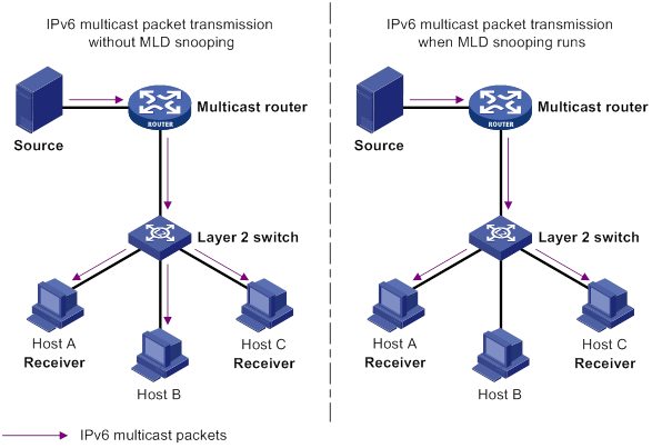
MLD snooping ports
As shown in Figure 76, MLD snooping runs on Switch A and Switch B, and Host A and Host C are receiver hosts in an IPv6 multicast group. MLD snooping ports are divided into member ports and router ports.

Router ports
On an MLD snooping Layer 2 device, the ports toward Layer 3 multicast devices are called router ports. In Figure 76, GigabitEthernet 1/0/1 of Switch A and GigabitEthernet 1/0/1 of Switch B are router ports.
Router ports contain the following types:
· Dynamic router port—When a port receives an MLD general query whose source address is not 0::0 or receives an IPv6 PIM hello message, the port is added into the dynamic router port list. At the same time, an aging timer is started for the port. If the port receives either of the messages before the timer expires, the timer is reset. If the port does not receive either of the messages when the timer expires, the port is removed from the dynamic router port list.
· Static router port—When a port is statically configured as a router port, it is added into the static router port list. The static router port does not age out, and it can be deleted only manually.
Do not confuse the "router port" in MLD snooping with the "routed interface" commonly known as the "Layer 3 interface." The router port in MLD snooping is a Layer 2 interface.
Member ports
On an MLD snooping Layer 2 device, the ports toward receiver hosts are called member ports. In Figure 76, GigabitEthernet 1/0/2 and GigabitEthernet 1/0/3 of Switch A and GigabitEthernet 1/0/2 of Switch B are member ports.
Member ports contain the following types:
· Dynamic member port—When a port receives an MLD report, it is added to the associated dynamic MLD snooping forwarding entry as an outgoing interface. At the same time, an aging timer is started for the port. If the port receives an MLD report before the timer expires, the timer is reset. If the port does not receive an MLD report when the timer expires, the port is removed from the associated dynamic forwarding entry.
· Static member port—When a port is statically configured as a member port, it is added to the associated static MLD snooping forwarding entry as an outgoing interface. The static member port does not age out, and it can be deleted only manually.
Unless otherwise specified, router ports and member ports in this document include both static and dynamic router ports and member ports.
How MLD snooping works
The ports in this section are dynamic ports. For information about how to configure and remove static ports, see "Configuring static ports."
General query
The MLD querier periodically sends MLD general queries to all hosts and routers on the local subnet to check for the existence of IPv6 multicast group members.
After receiving an MLD general query, the Layer 2 device forwards the query to all ports in the VLAN except the receiving port. The Layer 2 device also performs one of the following actions:
· If the receiving port is a dynamic router port in the dynamic router port list, the Layer 2 device restarts the aging timer for the router port.
· If the receiving port does not exist in the dynamic router port list, the Layer 2 device adds the port to the dynamic router port list. It also starts an aging timer for the port.
MLD report
A host sends an MLD report to the MLD querier for the following purposes:
· Responds to queries if the host is an IPv6 multicast group member.
· Applies for an IPv6 multicast group membership.
After receiving an MLD report from a host, the Layer 2 device forwards the report through all the router ports in the VLAN. It also resolves the IPv6 address of the reported IPv6 multicast group, and looks up the forwarding table for a matching entry as follows:
· If no match is found, the Layer 2 device creates a forwarding entry for the group with the receiving port an outgoing interface. It also marks the receiving port as a dynamic member port and starts an aging timer for the port.
· If a match is found but the matching forwarding entry does not contain the receiving port, the Layer 2 device adds the receiving port to the outgoing interface list. It also marks the port as a dynamic member port to the forwarding entry and starts an aging timer for the port.
· If a match is found and the matching forwarding entry contains the receiving port, the Layer 2 device restarts the aging timer for the port.
In an application with an IPv6 multicast group policy configured on an MLD snooping-enabled Layer 2 device, when a user requests a multicast program, the user's host initiates an MLD report. After receiving this report message, the Layer 2 device resolves the IPv6 multicast group address in the report and performs ACL filtering on the report. If the report passes ACL filtering, the Layer 2 device creates an MLD snooping forwarding entry for the group with the receiving port as an outgoing interface. If the report does not pass ACL filtering, the Layer 2 device drops this report message, in which case, the IPv6 multicast data for the IPv6 multicast group is not sent to this port, and the user cannot retrieve the program.
A Layer 2 device does not forward an MLD report through a non-router port because of the host MLD report suppression mechanism. For more information about the MLD report suppression mechanism, see "Configuring MLD."
Done message
When a host leaves an IPv6 multicast group, the host sends an MLD done message to the Layer 3 devices. When the Layer 2 device receives the MLD done message on a dynamic member port, the Layer 2 device first examines whether a forwarding entry matches the IPv6 multicast group address in the message.
· If no match is found, the Layer 2 device discards the MLD done message.
· If a match is found but the receiving port is not an outgoing interface in the forwarding entry, the Layer 2 device discards the MLD done message.
· If a match is found and the receiving port is not the only outgoing interface in the forwarding entry, the Layer 2 device performs the following actions:
? Discards the MLD done message.
? Sends an MLD multicast-address-specific query to identify whether the group has active listeners attached to the receiving port.
? Sets the aging timer for the receiving port to twice the MLD last listener query interval.
· If a match is found and the receiving port is the only outgoing interface in the forwarding entry, the Layer 2 device performs the following actions:
? Forwards the MLD done message to all router ports in the VLAN.
? Sends an MLD multicast-address-specific query to identify whether the group has active listeners attached to the receiving port.
? Sets the aging timer for the receiving port to twice the MLD last listener query interval.
After receiving the MLD done message on a port, the MLD querier resolves the IPv6 multicast group address in the message. Then, it sends an MLD multicast-address-specific query to the IPv6 multicast group through the receiving port.
After receiving the MLD multicast-address-specific query, the Layer 2 device forwards the query through all its router ports in the VLAN and all member ports of the IPv6 multicast group. Then, it waits for the responding MLD report from the directly connected hosts. For the dynamic member port that received the done message, the Layer 2 device also performs one of the following actions:
· If the port receives an MLD report before the aging timer expires, the Layer 2 device resets the aging timer for the port.
· If the port does not receive any MLD report messages when the aging timer expires, the Layer 2 device removes the port from the forwarding entry for the IPv6 multicast group.
Protocols and standards
RFC 4541, Considerations for Internet Group Management Protocol (IGMP) and Multicast Listener Discovery (MLD) Snooping Switches
Compatibility information
Feature and hardware compatibility
This feature is supported only on the following ports:
· Layer 2 Ethernet ports on the following modules:
? HMIM-8GSW.
? HMIM-8GSWF.
? HMIM-24GSW/24GSW-PoE.
? SIC-4GSW/4GSWF/4GSW-PoE.
? SIC-9FSW/9FSW-PoE.
· Fixed Layer 2 Ethernet ports on the following routers:
? MSR2600-6-X1/2600-10-X1
? MSR3600-28/3600-51.
Command and hardware compatibility
Commands and descriptions for centralized devices apply to the following routers:
· MSR2600-6-X1/2600-10-X1.
· MSR 2630.
· MSR3600-28/3600-51.
· MSR3610-X1/3610-X1-DP/3610-X1-DC/3610-X1-DP-DC.
· MSR 3610/3620/3620-DP/3640/3660.
· MSR810-LM-GL/810-W-LM-GL/830-6EI-GL/830-10EI-GL/830-6HI-GL/830-10HI-GL/2600-6-X1-GL.
Commands and descriptions for distributed devices apply to the following routers:
· MSR5620.
· MSR 5660.
· MSR 5680.
MLD snooping configuration task list
You can configure MLD snooping for VLANs.
The MLD snooping configurations made on Layer 2 aggregate interfaces do not interfere with the configurations made on member ports. In addition, the configurations made on Layer 2 aggregate interfaces do not take part in aggregation calculations. The configuration made on a member port of the aggregate group takes effect after the port leaves the aggregate group.
Configuring basic MLD snooping features
Before you configure basic MLD snooping features, complete the following tasks:
· Configure VLANs.
· Determine the MLD snooping version.
· Determine the maximum number of MLD snooping forwarding entries.
· Determine the MLD last listener query interval.
Enabling MLD snooping
When you enable MLD snooping, follow these restrictions and guidelines:
· You must enable MLD snooping globally before you can enable it for a VLAN.
· MLD snooping configuration made in VLAN view takes effect only on the member ports in that VLAN.
· You can enable MLD snooping for the specified VLANs in MLD-snooping view or for a VLAN in VLAN view. For a VLAN, the configuration in VLAN interface has the same priority as the configuration in MLD-snooping view, and the most recent configuration takes effect.
To enable MLD snooping for the specified VLANs:
|
Step |
Command |
Remarks |
|
1. Enter system view. |
system-view |
N/A |
|
2. Enable MLD snooping globally and enter MLD-snooping view. |
mld-snooping |
By default, MLD snooping is globally disabled. |
|
3. Enable MLD snooping for the specified VLANs. |
enable vlan vlan-list |
By default, MLD snooping is disabled for a VLAN. |
To enable MLD snooping for a VLAN:
|
Step |
Command |
Remarks |
|
1. Enter system view. |
system-view |
N/A |
|
2. Enable MLD snooping globally and enter MLD-snooping view. |
mld-snooping |
By default, MLD snooping is globally disabled. |
|
3. Return to system view. |
quit |
N/A |
|
4. Enter VLAN view. |
vlan vlan-id |
N/A |
|
5. Enable MLD snooping for the VLAN. |
mld-snooping enable |
By default, MLD snooping is disabled in a VLAN. |
Specifying an MLD snooping version
Different MLD snooping versions can process different versions of MLD messages:
· MLDv1 snooping can process MLDv1 messages, but it floods MLDv2 messages in the VLAN instead of processing them.
· MLDv2 snooping can process MLDv1 and MLDv2 messages.
If you change MLDv2 snooping to MLDv1 snooping, the system does the following:
· Clears all MLD snooping forwarding entries that are dynamically created.
· Keeps static MLDv2 snooping forwarding entries (*, G).
· Clears static MLDv2 snooping forwarding entries (S, G), which will be restored when MLD snooping is switched back to MLDv2 snooping.
For more information about static MLD snooping forwarding entries, see "Configuring static ports."
You can specify the version for the specified VLANs in MLD-snooping view or for a VLAN in VLAN view. For a VLAN, the configuration in VLAN view has the same priority as the configuration in MLD-snooping view, and the most recent configuration takes effect.
To specify an MLD snooping version for the specified VLANs:
|
Step |
Command |
Remarks |
|
1. Enter system view. |
system-view |
N/A |
|
2. Enable MLD snooping globally and enter MLD-snooping view. |
mld-snooping |
N/A |
|
3. Specify an MLD snooping version for the specified VLANs. |
version version-number vlan vlan-list |
The default setting is 1. |
To specify an MLD snooping version for a VLAN:
|
Step |
Command |
Remarks |
|
1. Enter system view. |
system-view |
N/A |
|
2. Enter VLAN view. |
vlan vlan-id |
N/A |
|
3. Specify an MLD snooping version for the VLAN. |
mld-snooping version version-number |
The default setting is 1. |
Setting the maximum number of MLD snooping forwarding entries
You can modify the maximum number of MLD snooping forwarding entries, including dynamic entries and static entries. When the number of forwarding entries on the device reaches the upper limit, the device does not automatically remove any existing entries. As a best practice, manually remove some entries to allow new entries to be created.
To set the maximum number of MLD snooping forwarding entries:
|
Step |
Command |
Remarks |
|
1. Enter system view. |
system-view |
N/A |
|
2. Enter MLD-snooping view. |
mld-snooping |
N/A |
|
3. Set the maximum number of MLD snooping forwarding entries. |
entry-limit limit |
The default setting is 4294967295. |
Setting the MLD last listener query interval
A receiver host starts a report delay timer for an IPv6 multicast group when it receives an MLD multicast-address-specific query for the group. This timer is set to a random value in the range of 0 to the maximum response time advertised in the query. When the timer value decreases to 0, the host sends an MLD report to the group.
The MLD last listener query interval defines the maximum response time advertised in MLD multicast-address-specific queries. Set an appropriate value for the MLD last listener query interval to speed up hosts' responses to MLD multicast-address-specific queries and avoid MLD report traffic bursts.
Configuration restrictions and guidelines
When you set the MLD last listener query interval, follow these restrictions and guidelines:
· The Layer 2 device does not send an MLD multicast-address-specific query if it receives an MLD done message from a port enabled with fast-leave processing.
· You can set the MLD last listener query interval globally for all VLANs in MLD-snooping view or for a VLAN in VLAN view. For a VLAN, the VLAN-specific configuration takes priority over the global configuration.
Setting the MLD last listener query interval globally
|
Step |
Command |
Remarks |
|
1. Enter system view. |
system-view |
N/A |
|
2. Enter MLD-snooping view. |
mld-snooping |
N/A |
|
3. Set the MLD last listener query interval globally. |
last-listener-query-interval interval |
The default setting is 1 second. |
Setting the MLD last listener query interval in a VLAN
|
Step |
Command |
Remarks |
|
1. Enter system view. |
system-view |
N/A |
|
2. Enter VLAN view. |
vlan vlan-id |
N/A |
|
3. Set the MLD last listener query interval in the VLAN. |
mld-snooping last-listener-query-interval interval |
The default setting is 1 second. |
Configuring MLD snooping port features
Before you configure MLD snooping port features, complete the following tasks:
· Enable MLD snooping for the VLAN.
· Determine the aging timer for dynamic router ports.
· Determine the aging timer for dynamic member ports.
· Determine the addresses of the IPv6 multicast group and IPv6 multicast source.
Setting aging timers for dynamic ports
When you set aging timers for dynamic ports, follow these restrictions and guidelines:
· If the memberships of IPv6 multicast groups frequently change, set a relatively small value for the aging timer of the dynamic member ports. If the memberships of IPv6 multicast groups rarely change, you can set a relatively large value.
· If a dynamic router port receives an IPv6 PIMv2 hello message, the aging timer for the port is specified by the hello message. In this case, the mld-snooping router-aging-time command does not take effect on the port.
· MLD multicast-address-specific queries originated by the Layer 2 device trigger the adjustment of aging timers of dynamic member ports. If a dynamic member port receives such a query, its aging timer is set to twice the MLD last listener query interval. For more information about setting the MLD last listener query interval on the Layer 2 device, see "Setting the MLD last listener query interval."
· You can set the timers globally for all VLANs in MLD-snooping view or for a VLAN in VLAN view. For a VLAN, the VLAN-specific configuration takes priority over the global configuration.
Setting the aging timers for dynamic ports globally
|
Step |
Command |
Remarks |
|
1. Enter system view. |
system-view |
N/A |
|
2. Enter MLD-snooping view. |
mld-snooping |
N/A |
|
3. Set the aging timer for dynamic router ports globally. |
router-aging-time seconds |
The default setting is 260 seconds. |
|
4. Set the aging timer for dynamic member ports globally. |
host-aging-time seconds |
The default setting is 260 seconds. |
Setting the aging timers for dynamic ports in a VLAN
|
Step |
Command |
Remarks |
|
1. Enter system view. |
system-view |
N/A |
|
2. Enter VLAN view. |
vlan vlan-id |
N/A |
|
3. Set the aging timer for dynamic router ports in the VLAN. |
mld-snooping router-aging-time seconds |
The default setting is 260 seconds. |
|
4. Set the aging timer for dynamic member ports in the VLAN. |
mld-snooping host-aging-time seconds |
The default setting is 260 seconds. |
Configuring static ports
You can configure the following types of static ports:
· Static member port—When you configure a port as a static member port for an IPv6 multicast group, all hosts attached to the port will receive IPv6 multicast data for the group.
The static member port does not respond to MLD queries. When you complete or cancel this configuration, the port does not send an unsolicited report or done message.
· Static router port—When you configure a port as a static router port for an IPv6 multicast group, all IPv6 multicast data for the group received on the port will be forwarded.
To configure static ports:
|
Step |
Command |
Remarks |
|
1. Enter system view. |
system-view |
N/A |
|
2. Enter Layer 2 Ethernet interface view or Layer 2 aggregate interface view. |
interface interface-type interface-number |
N/A |
|
3. Configure the port as a static port. |
·
Configure the port as a static member port: ·
Configure the port as a static router port: |
By default, a port is not a static member port or a static router port. |
Configuring a port as a simulated member host
When a port is configured as a simulated member host, it is equivalent to an independent host in the following ways:
· It sends an unsolicited MLD report when you complete the configuration.
· It responds to MLD general queries with MLD reports.
· It sends an MLD done message when you remove the configuration.
The version of MLD running on the simulated member host is the same as the version of MLD snooping running on the port. The port ages out in the same ways as a dynamic member port.
To configure a port as a simulated member host:
|
Step |
Command |
Remarks |
|
1. Enter system view. |
system-view |
N/A |
|
2. Enter Layer 2 Ethernet interface view or Layer 2 aggregate interface view. |
N/A |
|
|
3. Configure the port as a simulated member host. |
mld-snooping host-join ipv6-group-address [ source-ip ipv6-source-address ] vlan vlan-id |
By default, the port is not a simulated member host. |
Enabling fast-leave processing
This feature enables the device to immediately remove a port from the forwarding entry for an IPv6 multicast group when the port receives a done message.
Configuration restrictions and guidelines
When you enable fast-leave processing, follow these restrictions and guidelines:
· Do not enable fast-leave processing on a port that have multiple receiver hosts attached in a VLAN. If fast-leave processing is enabled, the remaining receivers cannot receive IPv6 multicast data for a group after a receiver leaves that group.
· You can enable fast-leave processing globally for all ports in MLD-snooping view or for a port in interface view. For a port, the port-specific configuration takes priority over the global configuration.
Configuration procedure
To enable fast-leave processing globally:
|
Step |
Command |
Remarks |
|
1. Enter system view. |
system-view |
N/A |
|
2. Enter MLD-snooping view. |
mld-snooping |
N/A |
|
3. Enable fast-leave processing globally. |
fast-leave [ vlan vlan-list ] |
By default, fast-leave processing is disabled globally. |
To enable fast-leave processing on a port:
|
Step |
Command |
Remarks |
|
1. Enter system view. |
system-view |
N/A |
|
2. Enter Layer 2 Ethernet interface view or Layer 2 aggregate interface view. |
interface interface-type interface-number |
N/A |
|
3. Enable fast-leave processing on the port. |
mld-snooping fast-leave [ vlan vlan-list ] |
By default, fast-leave processing is disabled on a port. |
Disabling a port from becoming a dynamic router port
A receiver host might send MLD general queries or IPv6 PIM hello messages for testing purposes. On the Layer 2 device, the port that receives either of the messages becomes a dynamic router port. Before the aging timer for the port expires, the following problems might occur:
· All IPv6 multicast data for the VLAN to which the port belongs flows to the port. Then, the port forwards the data to attached receiver hosts. The receiver hosts will receive IPv6 multicast data that it does not expect.
· The port forwards the MLD general queries or IPv6 PIM hello messages to its upstream multicast routers. These messages might affect the multicast routing protocol state (such as the MLD querier or DR election) on the multicast routers. This might further cause network interruption.
To solve these problems, you can disable the router port from becoming a dynamic router port when receiving either of the messages. This also improves network security and the control over receiver hosts.
To disable a port from becoming a dynamic router port:
|
Step |
Command |
Remarks |
|
1. Enter system view. |
system-view |
N/A |
|
2. Enter Layer 2 Ethernet interface view or Layer 2 aggregate interface view. |
N/A |
|
|
3. Disable the port from becoming a dynamic router port. |
mld-snooping router-port-deny [ vlan vlan-list ] |
By default, a port is allowed to become a dynamic router port. This configuration does not affect the static router port configuration. |
Configuring the MLD snooping querier
This section describes how to configure the MLD snooping querier.
Configuration prerequisites
Before you configure the MLD snooping querier, complete the following tasks:
· Enable MLD snooping for the VLAN.
· Determine the MLD general query interval.
· Determine the maximum response time for MLD general queries.
Enabling the MLD snooping querier
This feature enables the device to periodically send MLD general queries to establish and maintain multicast forwarding entries at the data link Layer. You can configure an MLD snooping querier on a network without Layer 3 multicast devices.
Configuration restrictions and guidelines
Do not enable the MLD snooping querier on an IPv6 multicast network that runs MLD. An MLD snooping querier does not participate in MLD querier elections. However, it might affect MLD querier elections if it sends MLD general queries with a low source IPv6 address.
Configuration procedure
To enable the MLD snooping querier for a VLAN:
|
Step |
Command |
Remarks |
|
1. Enter system view. |
system-view |
N/A |
|
2. Enter VLAN view. |
vlan vlan-id |
N/A |
|
3. Enable the MLD snooping querier for the VLAN. |
mld-snooping querier |
By default, the MLD snooping querier is disabled for a VLAN. |
Configuring parameters for MLD general queries and responses
|
|
CAUTION: To avoid mistakenly deleting IPv6 multicast group members, make sure the MLD general query interval is greater than the maximum response time for MLD general queries. |
You can modify the MLD general query interval for a VLAN based on the actual network conditions.
A receiver host starts a report delay timer for each IPv6 multicast group that it has joined when it receives an MLD general query. This timer is set to a random value in the range of 0 to the maximum response time advertised in the query. When the timer value decreases to 0, the host sends an MLD report to the corresponding IPv6 multicast group.
Set an appropriate value for the maximum response time for MLD general queries to speed up hosts' responses to MLD general queries and avoid MLD report traffic bursts.
You can configure the parameters globally for all VLANs in MLD-snooping view or for a VLAN in VLAN view. For a VLAN, the VLAN-specific configuration takes priority over the global configuration.
Configuring parameters for MLD general queries and responses globally
|
Step |
Command |
Remarks |
|
1. Enter system view. |
system-view |
N/A |
|
2. Enter MLD-snooping view. |
mld-snooping |
N/A |
|
3. Set the maximum response time for MLD general queries. |
max-response-time seconds |
The default setting is 10 seconds. |
Configuring parameters for MLD general queries and responses in a VLAN
|
Step |
Command |
Remarks |
|
1. Enter system view. |
system-view |
N/A |
|
2. Enter VLAN view. |
vlan vlan-id |
N/A |
|
3. Set the MLD general query interval in the VLAN. |
The default setting is 125 seconds. |
|
|
4. Set the maximum response time for MLD general queries in the VLAN. |
mld-snooping max-response-time seconds |
The default setting is 10 seconds. |
Configuring parameters for MLD messages
This section describes how to configure parameters for MLD messages.
Configuration prerequisites
Before you configure parameters for MLD messages, complete the following tasks:
· Enable MLD snooping for the VLAN.
· Determine the source IPv6 address of MLD general queries.
· Determine the source IPv6 address of MLD multicast-address-specific queries.
· Determine the source IPv6 address of MLD reports.
· Determine the source IPv6 address of MLD done messages.
· Determine the 802.1p priority of MLD messages.
Configuring source IPv6 addresses for MLD messages
You can change the source IPv6 address of the MLD queries sent by an MLD snooping querier. This configuration might affect MLD querier election within the subnet.
You can also change the source IPv6 address of MLD reports or done messages sent by a simulated member host or an MLD snooping proxy.
To configure the source IP address for MLD messages in a VLAN:
|
Step |
Command |
Remarks |
|
1. Enter system view. |
system-view |
N/A |
|
2. Enter VLAN view. |
vlan vlan-id |
N/A |
|
3. Configure the source IPv6 address for MLD general queries. |
mld-snooping general-query source-ip ipv6-address |
By default, the source IPv6 address of MLD general queries is the IPv6 link-local address of the current VLAN interface. If the current VLAN interface does not have an IPv6 link-local address, the source IPv6 address is FE80::02FF:FFFF:FE00:0001. |
|
4. Configure the source IPv6 address for MLD multicast-address-specific queries. |
mld-snooping special-query source-ip ipv6-address |
By default, the source IPv6 link-local address of MLD multicast-address-specific queries is one of the following: · The source address of MLD general queries if the MLD snooping querier has received MLD general queries. · The IPv6 link-local address of the current VLAN interface if the MLD snooping querier does not receive an MLD general query. · FE80::02FF:FFFF:FE00:0001 if the MLD snooping querier does not receive an MLD general query and the current VLAN interface does not have an IPv6 link-local address. |
|
5. Configure the source IPv6 address for MLD reports. |
By default, the source IPv6 address of MLD reports is the IPv6 link-local address of the current VLAN interface. If the current VLAN interface does not have an IPv6 link-local address, the source IPv6 address is FE80::02FF:FFFF:FE00:0001. |
|
|
6. Configure the source IPv6 address for MLD done messages. |
By default, the source IPv6 address of MLD done messages is the IPv6 link-local address of the current VLAN interface. If the current VLAN interface does not have an IPv6 link-local address, the source IPv6 address is FE80::02FF:FFFF:FE00:0001. |
Setting the 802.1p priority for MLD messages
When congestion occurs on outgoing ports of the Layer 2 device, it forwards MLD messages in their 802.1p priority order, from highest to lowest. You can assign a higher 802.1p priority to MLD messages that are created or forwarded by the device.
You can configure the 802.1p priority of MLD messages for all VLANs in MLD-snooping view or for a VLAN in VLAN view. For a VLAN, the VLAN-specific configuration takes priority over the global configuration.
Setting the 802.1p priority for MLD messages globally
|
Step |
Command |
Remarks |
|
1. Enter system view. |
system-view |
N/A |
|
2. Enter MLD-snooping view. |
mld-snooping |
N/A |
|
3. Set the 802.1p priority for MLD messages. |
dot1p-priority priority |
By default, the 802.1p priority for MLD messages is not set. |
Setting the 802.1p priority for MLD messages in a VLAN
|
Step |
Command |
Remarks |
|
1. Enter system view. |
system-view |
N/A |
|
2. Enter VLAN view. |
vlan vlan-id |
N/A |
|
3. Set the 802.1p priority for MLD messages in the VLAN. |
mld-snooping dot1p-priority priority |
By default, the 802.1p priority for MLD messages is not set. |
Configuring MLD snooping policies
Before you configure MLD snooping policies, complete the following tasks:
· Enable MLD snooping for the VLAN.
· Determine the ACL used by the IPv6 multicast group policy.
· Determine the maximum number of IPv6 multicast groups that a port can join.
Configuring an IPv6 multicast group policy
This feature enables the device to filter MLD reports by using an ACL that specifies the IPv6 multicast groups and the optional sources. It is used to control the IPv6 multicast groups that receiver hosts can join.
Configuration restrictions and guidelines
When you configure an IPv6 multicast group policy, follow these restrictions and guidelines:
· This configuration takes effect on the IPv6 multicast groups that ports join dynamically.
· You can configure an IPv6 multicast group policy globally for all ports in MLD-snooping view or for a port in interface view. For a port, the port-specific configuration takes priority over the global configuration.
Configuration procedure
To configure an IPv6 multicast group policy globally:
|
Step |
Command |
Remarks |
|
1. Enter system view. |
system-view |
N/A |
|
2. Enter MLD-snooping view. |
mld-snooping |
N/A |
|
3. Configure an IPv6 multicast group policy globally. |
group-policy ipv6-acl-number [ vlan vlan-list ] |
By default, no IPv6 multicast group policies exist, and host can join any IPv6 multicast groups. |
To configure an IPv6 multicast group policy on a port:
|
Step |
Command |
Remarks |
|
1. Enter system view. |
system-view |
N/A |
|
2. Enter Layer 2 Ethernet interface view or Layer 2 aggregate interface view. |
interface interface-type interface-number |
N/A |
|
3. Configure an IPv6 multicast group policy for the port. |
mld-snooping group-policy ipv6-acl-number [ vlan vlan-list ] |
By default, no IPv6 multicast group policies exist on a port, and hosts attached to the port can join any IPv6 multicast groups. |
Enabling IPv6 multicast source port filtering
This feature is supported only on the following ports:
· Layer 2 Ethernet ports on the following modules:
? HMIM-8GSW.
? HMIM-8GSWF.
? HMIM-24GSW/24GSW-PoE.
· Fixed Layer 2 Ethernet ports on the following routers:
? MSR2600-6-X1/2600-10-X1.
? MSR3600-28/3600-51.
This feature enables the device to discard all IPv6 multicast data packets and to accept IPv6 multicast protocol packets. You can enable this feature on ports that connect to only IPv6 multicast receivers.
You can enable multicast source port filtering for the specified ports in MLD-snooping view or for a port in interface view. For a port, the configuration in interface view has the same priority as the configuration in MLD-snooping view, and the most recent configuration takes effect.
Enabling IPv6 multicast source port filtering for the specified ports
|
Step |
Command |
Remarks |
|
1. Enter system view. |
system-view |
N/A |
|
2. Enter MLD-snooping view. |
mld-snooping |
N/A |
|
3. Enable IPv6 multicast source port filtering globally. |
source-deny port interface-list |
By default, IPv6 multicast source port filtering is disabled globally. |
Enabling IPv6 multicast source port filtering for a port
|
Step |
Command |
Remarks |
|
1. Enter system view. |
system-view |
N/A |
|
2. Enter Layer 2 Ethernet interface view. |
interface interface-type interface-number |
N/A |
|
3. Enable IPv6 multicast source port filtering on the port. |
mld-snooping source-deny |
By default, IPv6 multicast source port filtering is disabled on the port. |
Enabling dropping unknown IPv6 multicast data
This feature is supported only on the following ports:
· Layer 2 Ethernet ports on the following modules:
? HMIM-8GSW.
? HMIM-8GSWF.
? HMIM-24GSW/24GSW-PoE.
? SIC-4GSW/4GSWF/4GSW-PoE.
· Fixed Layer 2 Ethernet ports on the following routers:
? MSR2600-6-X1/2600-10-X1.
? MSR3600-28/3600-51.
This feature enables the device to drop all unknown IPv6 multicast data. Unknown IPv6 multicast data refers to IPv6 multicast data for which no forwarding entries exist in the MLD snooping forwarding table.
If you do not enable this feature, the unknown IPv6 multicast data is flooded in the VLAN to which the data belongs.
For a device installed with the SIC-4GSW, SIC-4GSWF, or SIC-4GSW-PoE module, unknown IPv4 multicast data is dropped for a VLAN enabled with dropping unknown IPv6 multicast data.
To enable dropping unknown IPv6 multicast data for a VLAN:
|
Step |
Command |
Remarks |
|
1. Enter system view. |
system-view |
N/A |
|
2. Enter VLAN view. |
vlan vlan-id |
N/A |
|
3. Enable dropping unknown IPv6 multicast data for the VLAN. |
mld-snooping drop-unknown |
By default, dropping unknown IPv6 multicast data is disabled, and unknown IPv6 multicast data is flooded. |
Enabling MLD report suppression
This feature enables the Layer 2 device to forward only the first MLD report for an IPv6 multicast group to its directly connected Layer 3 device. Other reports for the same group in the same query interval are discarded. Use this feature to reduce the multicast traffic.
To enable MLD report suppression:
|
Step |
Command |
Remarks |
|
1. Enter system view. |
system-view |
N/A |
|
2. Enter MLD-snooping view. |
mld-snooping |
N/A |
|
3. Enable MLD report suppression. |
report-aggregation |
By default, MLD report suppression is enabled. |
Setting the maximum number of IPv6 multicast groups on a port
You can set the maximum number of IPv6 multicast groups on a port to regulate the port traffic.
Configuration restrictions and guidelines
When you set the maximum number of IPv6 multicast groups on a port, follow these restrictions and guidelines:
· This configuration takes effect only on the IPv6 multicast groups that the port joins dynamically.
· If the number of IPv6 multicast groups on a port exceeds the limit, the system removes all the forwarding entries related to that port. In this case, the receiver hosts attached to that port can join IPv6 multicast groups again before the number of IPv6 multicast groups on the port reaches the limit.
Configuration procedure
To set the maximum number of IPv6 multicast groups on a port:
|
Step |
Command |
Remarks |
|
1. Enter system view. |
system-view |
N/A |
|
2. Enter Layer 2 Ethernet interface view or Layer 2 aggregate interface view. |
interface interface-type interface-number |
N/A |
|
3. Set the maximum number of IPv6 multicast groups on the port. |
mld-snooping group-limit limit [ vlan vlan-list ] |
By default, no limit is placed on the maximum number of IPv6 multicast groups on a port. |
Enabling the IPv6 multicast group replacement feature
This feature enables the device to replace an existing group with a newly joined group when the number of groups exceeds the upper limit. This feature is typically used in the channel switching application. Without this feature, the device discards MLD reports for new groups, and the user cannot change to the new channel.
Configuration restrictions and guidelines
When you enable the IPv6 multicast group replacement feature, follow these restrictions and guidelines:
· This configuration takes effect only on the multicast groups that the port joins dynamically.
· You can enable this feature globally for all ports in MLD-snooping view or for a port in interface view. For a port, the port-specific configuration takes priority over the global configuration.
Configuration procedure
To enable the IPv6 multicast group replacement feature globally:
|
Step |
Command |
Remarks |
|
1. Enter system view. |
system-view |
N/A |
|
2. Enter MLD-snooping view. |
mld-snooping |
N/A |
|
3. Enable the IPv6 multicast group replacement feature globally. |
overflow-replace [ vlan vlan-list ] |
By default, the IPv6 multicast group replacement feature is disabled globally. |
To enable the IPv6 multicast group replacement on a port:
|
Step |
Command |
Remarks |
|
1. Enter system view. |
system-view |
N/A |
|
2. Enter Layer 2 Ethernet interface view or Layer 2 aggregate interface view. |
interface interface-type interface-number |
N/A |
|
3. Enable the IPv6 multicast group replacement feature on the port. |
mld-snooping overflow-replace [ vlan vlan-list ] |
By default, the IPv6 multicast group replacement feature is disabled on a port. |
Displaying and maintaining MLD snooping
Execute display commands in any view and reset commands in user view.
|
Task |
Command |
|
Display Layer 2 IPv6 multicast fast forwarding entries (centralized devices in standalone mode). |
display ipv6 l2-multicast fast-forwarding cache [ vlan vlan-id ] [ ipv6-source-address | ipv6-group-address ] * |
|
Display Layer 2 IPv6 multicast fast forwarding entries (distributed devices in standalone mode/centralized devices in IRF mode). |
display ipv6 l2-multicast fast-forwarding cache [ vlan vlan-id ] [ ipv6-source-address | ipv6-group-address ] * [ slot slot-number ] |
|
Display Layer 2 IPv6 multicast fast forwarding entries (distributed devices in IRF mode). |
display ipv6 l2-multicast fast-forwarding cache [ vlan vlan-id ] [ ipv6-source-address | ipv6-group-address ] * [ chassis chassis-number slot slot-number ] |
|
Display information about Layer 2 IPv6 multicast groups (centralized devices in standalone mode). |
display ipv6 l2-multicast ip [ group ipv6-group-address | source ipv6-source-address ] * [ vlan vlan-id ] |
|
Display information about Layer 2 IPv6 multicast groups (distributed devices in standalone mode/centralized devices in IRF mode). |
display ipv6 l2-multicast ip [ group ipv6-group-address | source ipv6-source-address ] * [ vlan vlan-id ] [ slot slot-number ] |
|
Display information about Layer 2 IPv6 multicast groups (distributed devices in IRF mode). |
display ipv6 l2-multicast ip [ group ipv6-group-address | source ipv6-source-address ] * [ vlan vlan-id ] [ chassis chassis-number slot slot-number ] |
|
Display Layer 2 IPv6 multicast group entries (centralized devices in standalone mode). |
display ipv6 l2-multicast ip forwarding [ group ipv6-group-address | source ipv6-source-address ] * [ vlan vlan-id ] |
|
Display Layer 2 IPv6 multicast group entries (distributed devices in standalone mode/centralized devices in IRF mode). |
display ipv6 l2-multicast ip forwarding [ group ipv6-group-address | source ipv6-source-address ] * [ vlan vlan-id ] [ slot slot-number ] |
|
Display Layer 2 IPv6 multicast group entries (distributed devices in IRF mode). |
display ipv6 l2-multicast ip forwarding [ group ipv6-group-address | source ipv6-source-address ] * [ vlan vlan-id ] [ chassis chassis-number slot slot-number ] |
|
Display information about Layer 2 IPv6 MAC multicast groups (centralized devices in standalone mode). |
display ipv6 l2-multicast mac [ mac-address ] [ vlan vlan-id ] |
|
Display information about Layer 2 IPv6 MAC multicast groups (distributed devices in standalone mode/centralized devices in IRF mode). |
display ipv6 l2-multicast mac [ mac-address ] [ vlan vlan-id ] [ slot slot-number ] |
|
Display information about Layer 2 IPv6 MAC multicast groups (distributed devices in IRF mode). |
display ipv6 l2-multicast mac [ mac-address ] [ vlan vlan-id ] [ chassis chassis-number slot slot-number ] |
|
Display Layer 2 IPv6 MAC multicast group entries (centralized devices in standalone mode). |
display ipv6 l2-multicast mac forwarding [ mac-address ] [ vlan vlan-id ] |
|
Display Layer 2 IPv6 MAC multicast group entries (distributed devices in standalone mode/centralized devices in IRF mode). |
display ipv6 l2-multicast mac forwarding [ mac-address ] [ vlan vlan-id ] [ slot slot-number ] |
|
Display Layer 2 IPv6 MAC multicast group entries (distributed devices in IRF mode). |
display ipv6 l2-multicast mac forwarding [ mac-address ] [ vlan vlan-id ] [ chassis chassis-number slot slot-number ] |
|
Display MLD snooping status. |
display mld-snooping [ global | vlan vlan-id ] |
|
Display dynamic MLD snooping group entries (centralized devices in standalone mode). |
display mld-snooping group [ ipv6-group-address | ipv6-source-address ] * [ vlan vlan-id ] [ verbose ] |
|
Display dynamic MLD snooping group entries (distributed devices in standalone mode/centralized devices in IRF mode). |
display mld-snooping group [ ipv6-group-address | ipv6-source-address ] * [ vlan vlan-id ] [ verbose ] [ slot slot-number ] |
|
Display dynamic MLD snooping group entries (distributed devices in IRF mode). |
display mld-snooping group [ ipv6-group-address | ipv6-source-address ] * [ vlan vlan-id ] [ verbose ] [ chassis chassis-number slot slot-number ] |
|
Display dynamic router port information (centralized devices in standalone mode). |
display mld-snooping router-port [ verbose | vlan vlan-id [ verbose ] ] |
|
Display dynamic router port information (distributed devices in standalone mode/centralized devices in IRF mode). |
display mld-snooping router-port [ verbose | vlan vlan-id [ verbose ] ] [ slot slot-number ] |
|
Display dynamic router port information (distributed devices in IRF mode). |
display mld-snooping router-port [ verbose | vlan vlan-id [ verbose ] ] [ chassis chassis-number slot slot-number ] |
|
Display static MLD snooping group entries (centralized devices in standalone mode). |
display mld-snooping static-group [ ipv6-group-address | ipv6-source-address ] * [ vlan vlan-id ] [ verbose ] |
|
Display static MLD snooping group entries (distributed devices in standalone mode/centralized devices in IRF mode). |
display mld-snooping static-group [ ipv6-group-address | ipv6-source-address ] * [ vlan vlan-id ] [ verbose ] [ slot slot-number ] |
|
Display static MLD snooping group entries (distributed devices in IRF mode). |
display mld-snooping static-group [ ipv6-group-address | ipv6-source-address ] * [ vlan vlan-id ] [ verbose ] [ chassis chassis-number slot slot-number ] |
|
Display static router port information (centralized devices in standalone mode). |
display mld-snooping static-router-port [ vlan vlan-id ] |
|
Display static router port information (distributed devices in standalone mode/centralized devices in IRF mode). |
display mld-snooping static-router-port [ vlan vlan-id ] [ slot slot-number ] |
|
Display static router port information (distributed devices in IRF mode). |
display mld-snooping static-router-port [ vlan vlan-id ] [ chassis chassis-number slot slot-number ] |
|
Display statistics for the MLD messages and IPv6 PIM hello messages learned through MLD snooping. |
display mld-snooping statistics |
|
Clear Layer 2 IPv6 multicast fast forwarding entries (centralized devices in standalone mode). |
reset ipv6 l2-multicast fast-forwarding cache [ vlan vlan-id ] { { ipv6-source-address | ipv6-group-address } * | all } |
|
Clear Layer 2 IPv6 multicast fast forwarding entries (distributed devices in standalone mode/centralized devices in IRF mode). |
reset ipv6 l2-multicast fast-forwarding cache [ vlan vlan-id ] { { ipv6-source-address | ipv6-group-address } * | all } [ slot slot-number ] |
|
Clear Layer 2 IPv6 multicast fast forwarding entries (distributed devices in IRF mode). |
reset ipv6 l2-multicast fast-forwarding cache [ vlan vlan-id ] { { ipv6-source-address | ipv6-group-address } * | all } [ chassis chassis-number slot slot-number ] |
|
Clear dynamic MLD snooping group entries. |
reset mld-snooping group { ipv6-group-address [ ipv6-source-address ] | all } [ vlan vlan-id ] |
|
Clear dynamic router port information. |
reset mld-snooping router-port { all | vlan vlan-id } |
|
Clear statistics for MLD messages and IPv6 PIM hello messages learned through MLD snooping. |
reset mld-snooping statistics |
MLD snooping configuration examples
IPv6 group policy and simulated joining configuration example
Network requirements
As shown in Figure 77, Router A runs MLDv1 and acts as the MLD querier, and Switch A runs MLDv1 snooping.
Configure the group policy and simulate joining to meet the following requirements:
· Host A and Host B receive only the IPv6 multicast data addressed to IPv6 multicast group FF1E::101. IPv6 multicast data can be forwarded through GigabitEthernet 1/0/3 and GigabitEthernet 1/0/4 of Switch A uninterruptedly, even though Host A and Host B fail to receive the multicast data.
· Switch A will drop unknown IPv6 multicast data instead of flooding it in VLAN 100.
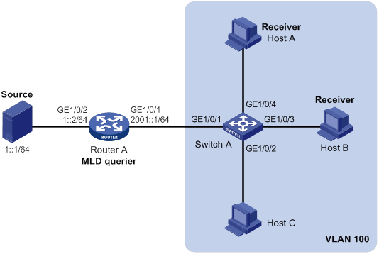
Configuration procedure
1. Assign an IPv6 address and prefix length to each interface, as shown in Figure 77. (Details not shown.)
2. Configure Router A:
# Enable IPv6 multicast routing.
<RouterA> system-view
[RouterA] ipv6 multicast routing
[RouterA-mrib6] quit
# Enable MLD on GigabitEthernet 1/0/1.
[RouterA] interface gigabitethernet 1/0/1
[RouterA-GigabitEthernet1/0/1] mld enable
[RouterA-GigabitEthernet1/0/1] quit
# Enable IPv6 PIM-DM on GigabitEthernet 1/0/2.
[RouterA] interface gigabitethernet 1/0/2
[RouterA-GigabitEthernet1/0/2] ipv6 pim dm
[RouterA-GigabitEthernet1/0/2] quit
3. Configure Switch A:
# Enable MLD snooping globally.
<SwitchA> system-view
[SwitchA] mld-snooping
[SwitchA-mld-snooping] quit
# Create VLAN 100, and assign GigabitEthernet 1/0/1 through GigabitEthernet 1/0/4 to the VLAN.
[SwitchA] vlan 100
[SwitchA-vlan100] port gigabitethernet 1/0/1 to gigabitethernet 1/0/4
# Enable MLD snooping, and enable dropping IPv6 unknown multicast data for VLAN 100.
[SwitchA-vlan100] mld-snooping enable
[SwitchA-vlan100] mld-snooping drop-unknown
[SwitchA-vlan100] quit
# Configure an IPv6 multicast group policy so that hosts in VLAN 100 can join only IPv6 multicast group FF1E::101.
[SwitchA] acl ipv6 basic 2001
[SwitchA-acl-ipv6-basic-2001] rule permit source ff1e::101 128
[SwitchA-acl-ipv6-basic-2001] quit
[SwitchA] mld-snooping
[SwitchA–mld-snooping] group-policy 2001 vlan 100
[SwitchA–mld-snooping] quit
# Configure GigabitEthernet 1/0/3 and GigabitEthernet 1/0/4 as simulated member hosts to join IPv6 multicast group FF1E::101.
[SwitchA] interface gigabitethernet 1/0/3
[SwitchA-GigabitEthernet1/0/3] mld-snooping host-join ff1e::101 vlan 100
[SwitchA-GigabitEthernet1/0/3] quit
[SwitchA] interface gigabitethernet 1/0/4
[SwitchA-GigabitEthernet1/0/4] mld-snooping host-join ff1e::101 vlan 100
[SwitchA-GigabitEthernet1/0/4] quit
Verifying the configuration
# Send MLD reports from Host A and Host B to join IPv6 multicast groups FF1E::101 and FF1E::202. (Details not shown.)
# Display dynamic MLD snooping group entries for VLAN 100 on Switch A.
[SwitchA] display mld-snooping group vlan 100
Total 1 entries.
VLAN 100: Total 1 entries.
(::, FF1E::101)
Host slots (0 in total):
Host ports (2 in total):
GE1/0/3 (00:03:23)
GE1/0/4 (00:04:10)
The output shows the following information:
· Host A and Host B have joined IPv6 multicast group FF1E::101 through the member ports GigabitEthernet 1/0/4 and GigabitEthernet 1/0/3 on Switch A, respectively.
· Host A and Host B have failed to join the multicast group FF1E::202.
Static port configuration example
Network requirements
As shown in Figure 78:
· Router A runs MLDv1 and acts as the MLD querier. Switch A, Switch B, and Switch C run MLDv1 snooping.
· Host A and Host C are permanent receivers of IPv6 multicast group FF1E::101.
Configure static ports to meet the following requirements:
· To enhance the reliability of IPv6 multicast traffic transmission, configure GigabitEthernet 1/0/3 and GigabitEthernet 1/0/5 on Switch C as static member ports for IPv6 multicast group FF1E::101.
· Suppose the STP runs on the network. To avoid data loops, the forwarding path from Switch A to Switch C is blocked. IPv6 multicast data flows to the receivers attached to Switch C only along the path of Switch A—Switch B—Switch C. When this path is blocked, a minimum of one MLD query-response cycle must be completed before IPv6 multicast data flows to the receivers along the path of Switch A—Switch C. In this case, the multicast delivery is interrupted during the process. For more information about the STP, see Layer 2—LAN Switching Configuration Guide.
Configure GigabitEthernet 1/0/3 on Switch A as a static router port. Then, IPv6 multicast data can flow to the receivers nearly uninterrupted along the path of Switch A—Switch C when the path of Switch A—Switch B—Switch C is blocked.
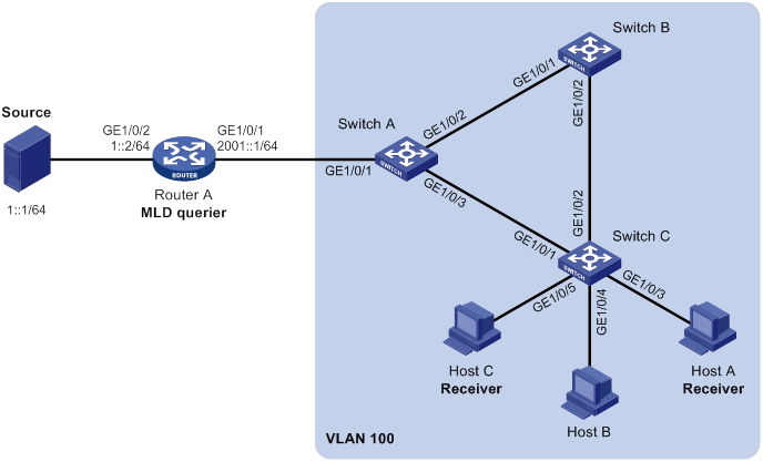
Configuration procedure
1. Assign an IPv6 address and prefix length to each interface, as shown in Figure 78. (Details not shown.)
2. Configure Router A:
# Enable IPv6 multicast routing.
<RouterA> system-view
[RouterA] ipv6 multicast routing
[RouterA-mrib6] quit
# Enable MLD on GigabitEthernet 1/0/1.
[RouterA] interface gigabitethernet 1/0/1
[RouterA-GigabitEthernet1/0/1] mld enable
[RouterA-GigabitEthernet1/0/1] quit
# Enable IPv6 PIM-DM on GigabitEthernet 1/0/2.
[RouterA] interface gigabitethernet 1/0/2
[RouterA-GigabitEthernet1/0/2] ipv6 pim dm
[RouterA-GigabitEthernet1/0/2] quit
3. Configure Switch A:
# Enable MLD snooping globally.
<SwitchA> system-view
[SwitchA] mld-snooping
[SwitchA-mld-snooping] quit
# Create VLAN 100, and assign GigabitEthernet 1/0/1 through GigabitEthernet 1/0/3 to the VLAN.
[SwitchA] vlan 100
[SwitchA-vlan100] port gigabitethernet 1/0/1 to gigabitethernet 1/0/3
# Enable MLD snooping for VLAN 100.
[SwitchA-vlan100] mld-snooping enable
[SwitchA-vlan100] quit
# Configure GigabitEthernet 1/0/3 as a static router port.
[SwitchA] interface gigabitethernet 1/0/3
[SwitchA-GigabitEthernet1/0/3] mld-snooping static-router-port vlan 100
[SwitchA-GigabitEthernet1/0/3] quit
4. Configure Switch B:
# Enable MLD snooping globally.
<SwitchB> system-view
[SwitchB] mld-snooping
[SwitchB-mld-snooping] quit
# Create VLAN 100, and assign GigabitEthernet 1/0/1 and GigabitEthernet 1/0/2 to the VLAN.
[SwitchB] vlan 100
[SwitchB-vlan100] port gigabitethernet 1/0/1 gigabitethernet 1/0/2
# Enable MLD snooping for VLAN 100.
[SwitchB-vlan100] mld-snooping enable
[SwitchB-vlan100] quit
5. Configure Switch C:
# Enable MLD snooping globally.
<SwitchC> system-view
[SwitchC] mld-snooping
[SwitchC-mld-snooping] quit
# Create VLAN 100, and assign GigabitEthernet 1/0/1 through GigabitEthernet 1/0/5 to the VLAN.
[SwitchC] vlan 100
[SwitchC-vlan100] port gigabitethernet 1/0/1 to gigabitethernet 1/0/5
# Enable MLD snooping for VLAN 100.
[SwitchC-vlan100] mld-snooping enable
[SwitchC-vlan100] quit
# Configure GigabitEthernet 1/0/3 and GigabitEthernet 1/0/5 as static member ports for IPv6 multicast group FF1E::101.
[SwitchC] interface gigabitethernet 1/0/3
[SwitchC-GigabitEthernet1/0/3] mld-snooping static-group ff1e::101 vlan 100
[SwitchC-GigabitEthernet1/0/3] quit
[SwitchC] interface gigabitethernet 1/0/5
[SwitchC-GigabitEthernet1/0/5] mld-snooping static-group ff1e::101 vlan 100
[SwitchC-GigabitEthernet1/0/5] quit
Verifying the configuration
# Display static router port information for VLAN 100 on Switch A.
[SwitchA] display mld-snooping static-router-port vlan 100
VLAN 100:
Router slots (0 in total):
Router ports (1 in total):
GE1/0/3
The output shows that GigabitEthernet 1/0/3 on Switch A has become a static router port.
# Display static MLD snooping group entries in VLAN 100 on Switch C.
[SwitchC] display mld-snooping static-group vlan 100
Total 1 entries).
VLAN 100: Total 1 entries).
(::, FF1E::101)
Host slots (0 in total):
Host ports (2 in total):
GE1/0/3
GE1/0/5
The output shows that GigabitEthernet 1/0/3 and GigabitEthernet 1/0/5 on Switch C have become static member ports of the IPv6 multicast group FF1E::101.
MLD snooping querier configuration example
Network requirements
As shown in Figure 79:
· The network is a Layer 2-only network.
· Source 1 and Source 2 send multicast data to IPv6 multicast groups FF1E::101 and FF1E::102, respectively.
· Host A and Host C are receivers of IPv6 multicast group FF1E::101, and Host B and Host D are receivers of IPv6 multicast group FF1E::102.
· All host receivers run MLDv1 and all switches run MLDv1 snooping. Switch A (which is close to the multicast sources) acts as the MLD snooping querier.
To prevent the switches from flooding unknown IPv6 packets in the VLAN, enable all the switches to drop unknown IPv6 multicast packets.
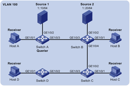
Configuration procedure
1. Configure Switch A:
# Enable MLD snooping globally.
[SwitchA] mld-snooping
[SwitchA-mld-snooping] quit
# Create VLAN 100, and assign GigabitEthernet 1/0/1 through GigabitEthernet 1/0/3 to the VLAN.
[SwitchA-vlan100] port gigabitethernet 1/0/1 to gigabitethernet 1/0/3
# Enable MLD snooping, and enable dropping unknown IPv6 multicast data for VLAN 100.
[SwitchA-vlan100] mld-snooping enable
[SwitchA-vlan100] mld-snooping drop-unknown
# Configure Switch A as the MLD snooping querier.
[SwitchA-vlan100] MLD-snooping querier
[SwitchA-vlan100] quit
2. Configure Switch B:
# Enable MLD snooping globally.
[SwitchB] mld-snooping
[SwitchB-mld-snooping] quit
# Create VLAN 100, and assign GigabitEthernet 1/0/1 through GigabitEthernet 1/0/4 to the VLAN.
[SwitchB] vlan 100
[SwitchB-vlan100] port gigabitethernet 1/0/1 to gigabitethernet 1/0/4
# Enable MLD snooping, and enable dropping unknown IPv6 multicast data for VLAN 100.
[SwitchB-vlan100] mld-snooping enable
[SwitchB-vlan100] mld-snooping drop-unknown
[SwitchB-vlan100] quit
3. Configure Switch C:
# Enable MLD snooping globally.
<SwitchC> system-view
[SwitchC] mld-snooping
[SwitchC-mld-snooping] quit
# Create VLAN 100, and assign GigabitEthernet 1/0/1 through GigabitEthernet 1/0/3 to the VLAN.
[SwitchC] vlan 100
[SwitchC-vlan100] port gigabitethernet 1/0/1 to gigabitethernet 1/0/3
# Enable MLD snooping, and enable dropping unknown IPv6 multicast data for VLAN 100.
[SwitchC-vlan100] mld-snooping enable
[SwitchC-vlan100] mld-snooping drop-unknown
[SwitchC-vlan100] quit
4. Configure Switch D:
# Enable MLD snooping globally.
[SwitchD] mld-snooping
[SwitchD-mld-snooping] quit
# Create VLAN 100, and assign GigabitEthernet 1/0/1 and GigabitEthernet 1/0/2 to the VLAN.
[SwitchD] vlan 100
[SwitchD-vlan100] port gigabitethernet 1/0/1 to gigabitethernet 1/0/2
# Enable MLD snooping, and enable dropping unknown IPv6 multicast data for VLAN 100.
[SwitchD-vlan100] mld-snooping enable
[SwitchD-vlan100] mld-snooping drop-unknown
[SwitchD-vlan100] quit
Verifying the configuration
# Display statistics for MLD messages and IPv6 PIM hello messages learned through MLD snooping on Switch B.
[SwitchB] display mld-snooping statistics
Received MLD general queries: 3
Received MLDv1 specific queries: 0
Received MLDv1 reports: 12
Received MLD dones: 0
Sent MLDv1 specific queries: 0
Received MLDv2 reports: 0
Received MLDv2 reports with right and wrong records: 0
Received MLDv2 specific queries: 0
Received MLDv2 specific sg queries: 0
Sent MLDv2 specific queries: 0
Sent MLDv2 specific sg queries: 0
Received IPv6 PIM hello: 0
Received error MLD messages: 0
The output shows that all switches except Switch A can receive the MLD general queries after Switch A acts as the MLD snooping querier.
Troubleshooting MLD snooping
Layer 2 multicast forwarding cannot function
Symptom
Layer 2 multicast forwarding cannot function through MLD snooping.
Solution
To resolve the problem:
1. Use the display mld-snooping command to display MLD snooping status.
2. If MLD snooping is not enabled, use the mld-snooping command in system view to enable MLD snooping globally. Then, use the mld-snooping enable command in VLAN view to enable MLD snooping for the VLAN.
3. If MLD snooping is enabled globally but not enabled for the VLAN, use the mld-snooping enable command in VLAN view to enable MLD snooping for the VLAN.
4. If the problem persists, contact H3C Support.
IPv6 multicast group policy does not work
Symptom
Hosts can receive IPv6 multicast data for IPv6 multicast groups that are not permitted by the IPv6 multicast group policy.
Solution
To resolve the problem:
1. Use the display acl ipv6 command to verify that the configured IPv6 ACL meets the IPv6 multicast group policy requirements.
2. Use the display this command in MLD-snooping view or in a corresponding interface view to verify that the correct IPv6 multicast group policy has been correctly applied. If it has not been applied, use the group-policy or mld-snooping group-policy command to apply the correct IPv6 multicast group policy.
3. Use the display mld-snooping command to verify that dropping unknown IPv6 multicast data is enabled. If it is not, use the mld-snooping drop-unknown command to enable dropping unknown IPv6 multicast data.
4. If the problem persists, contact H3C Support.
Configuring IPv6 multicast routing and forwarding
Overview
IPv6 multicast routing and forwarding uses the following tables:
· IPv6 multicast protocols' routing tables, such as the IPv6 PIM routing table.
· General IPv6 multicast routing table that summarizes the multicast routing information generated by different IPv6 multicast routing protocols. The IPv6 multicast routing information from IPv6 multicast sources to IPv6 multicast groups are stored in a set of (S, G) routing entries.
· IPv6 multicast forwarding table that guides IPv6 multicast forwarding. The optimal routing entries in the IPv6 multicast routing table are added to the IPv6 multicast forwarding table.
RPF check mechanism
An IPv6 multicast routing protocol uses the reverse path forwarding (RPF) check mechanism to ensure IPv6 multicast data delivery along the correct path and to avoid data loops.
RPF check process
An IPv6 multicast router performs the RPF check on an IPv6 multicast packet as follows:
1. The router chooses an optimal route back to the packet source separately from the IPv6 unicast and IPv6 MBGP routing tables.
In RPF check, the "packet source" means difference things in difference situations:
? For a packet that travels along the SPT, the packet source is the IPv6 multicast source.
? For a packet that travels along the RPT, the packet source is the RP.
? For a bootstrap message originated from the BSR, the packet source is the BSR.
For more information about the concepts of SPT, RPT, source-side RPT, RP, and BSR, see "Configuring IPv6 PIM."
2. The router selects one of the optimal routes as the RPF route as follows:
? If the router uses the longest prefix match principle, the route with a higher prefix length becomes the RPF route. If the routes have the same prefix length, the route with a higher route preference becomes the RPF route. If the routes have the same route preference, the IPv6 MBGP route becomes the RPF route.
For more information about the route preference, see Layer 3—IP Routing Configuration Guide.
? If the router does not use the longest prefix match principle, the route with a higher route preference becomes the RPF route. If the routes have the same route preference, the IPv6 MBGP route becomes the RPF route.
In the RPF route, the outgoing interface is the RPF interface and the next hop is the RPF neighbor.
3. The router checks whether the packet arrived at the RPF interface. If yes, the RPF check succeeds and the packet is forwarded. If not, the RPF check fails and the packet is discarded.
RPF check implementation in IPv6 multicast
Implementing an RPF check on each received IPv6 multicast packet would heavily burden the router. The use of an IPv6 multicast forwarding table is the solution to this issue. When the router creates an IPv6 multicast forwarding entry for an IPv6 (S, G) packet, it sets the RPF interface of the packet as the incoming interface of the (S, G) entry. After the router receives another (S, G) packet, it looks up its IPv6 multicast forwarding table for a matching (S, G) entry:
· If no match is found, the router first determines the RPF route back to the packet source. Then, it creates a forwarding entry with the RPF interface as the incoming interface and performs one of the following tasks:
? If the receiving interface is the RPF interface, the RPF check succeeds and the router forwards the packet out of all outgoing interfaces.
? If the receiving interface is not the RPF interface, the RPF check fails and the router discards the packet.
· If a match is found and the matching forwarding entry contains the receiving interface, the router forwards the packet out of all outgoing interfaces.
· If a match is found but the matching forwarding entry does not contain the receiving interface, the router determines the RPF route back to the packet source. Then, the router performs one of the following tasks:
? If the RPF interface is the incoming interface, it means that the forwarding entry is correct but the packet traveled along a wrong path. The packet fails the RPF check, and the router discards the packet.
? If the RPF interface is not the incoming interface, it means that the forwarding entry has expired. The router replaces the incoming interface with the RPF interface and matches the receiving interface against the RPF interface. If the receiving interface is the RPF interface, the router forwards the packet out of all outgoing interfaces. Otherwise, it discards the packet.
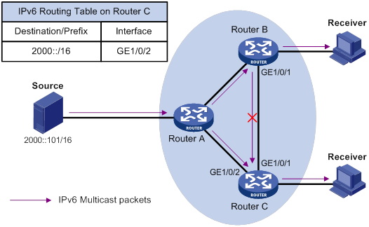
As shown in Figure 80, assume that IPv6 unicast routes are available on the network. IPv6 MBGP is not configured. IPv6 multicast packets travel along the SPT from the multicast source to the receivers. The IPv6 multicast forwarding table on Router C contains the (S, G) entry, with GigabitEthernet 1/0/2 as the RPF interface.
· If an IPv6 multicast packet arrives at Router C on GigabitEthernet 1/0/2, the receiving interface is the incoming interface of the (S, G) entry. Router C forwards the packet out of all outgoing interfaces.
· If an IPv6 multicast packet arrives at Router C on GigabitEthernet 1/0/1, the receiving interface is not the incoming interface of the (S, G) entry. Router C searches its IPv6 unicast routing table and finds that the outgoing interface to the source (the RPF interface) is GigabitEthernet 1/0/2. This means that the (S, G) entry is correct but the packet traveled along a wrong path. The packet fails the RPF check, and Router C discards the packet.
IPv6 multicast forwarding across IPv6 unicast subnets
Routers forward the IPv6 multicast data from an IPv6 multicast source hop by hop along the forwarding tree, but some routers might not support IPv6 multicast protocols in a network. When the IPv6 multicast data is forwarded to a router that does not support IPv6 multicast, the forwarding path is blocked. In this case, you can enable IPv6 multicast data forwarding across the IPv6 unicast subnets by establishing a tunnel between the routers at both ends of the IPv6 unicast subnets.
Figure 81 IPv6 multicast data transmission through a tunnel
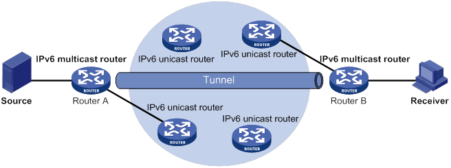
As shown in Figure 81, a tunnel is established between the multicast routers Router A and Router B. Router A encapsulates the IPv6 multicast data in unicast IPv6 packets, and forwards them to Router B across the tunnel through unicast routers. Then, Router B strips off the unicast IPv6 header and continues to forward the IPv6 multicast data down toward the receivers.
Compatibility information
Feature and hardware compatibility
The following matrix shows the feature and hardware compatibility:
|
Hardware |
IPv6 multicast routing and forwarding compatibility |
|
MSR810/810-W/810-W-DB/810-LM/810-W-LM/810-10-PoE/810-LM-HK/810-W-LM-HK/810-LMS/810-LUS |
No |
|
MSR2600-6-X1/2600-10-X1 |
Yes |
|
MSR 2630 |
Yes |
|
MSR3600-28/3600-51 |
Yes |
|
MSR3600-28-SI/3600-51-SI |
No |
|
MSR3610-X1/3610-X1-DP/3610-X1-DC/3610-X1-DP-DC |
Yes |
|
MSR 3610/3620/3620-DP/3640/3660 |
Yes |
|
MSR5620/5660/5680 |
Yes |
|
Hardware |
IPv6 multicast routing and forwarding compatibility |
|
MSR810-LM-GL |
Yes |
|
MSR810-W-LM-GL |
Yes |
|
MSR830-6EI-GL |
Yes |
|
MSR830-10EI-GL |
Yes |
|
MSR830-6HI-GL |
Yes |
|
MSR830-10HI-GL |
Yes |
|
MSR2600-6-X1-GL |
Yes |
|
MSR3600-28-SI-GL |
No |
Command and hardware compatibility
Commands and descriptions for centralized devices apply to the following routers:
· MSR2600-6-X1/2600-10-X1.
· MSR 2630.
· MSR3600-28/3600-51.
· MSR3610-X1/3610-X1-DP/3610-X1-DC/3610-X1-DP-DC.
· MSR 3610/3620/3620-DP/3640/3660.
· MSR810-LM-GL/810-W-LM-GL/830-6EI-GL/830-10EI-GL/830-6HI-GL/830-10HI-GL/2600-6-X1-GL.
Commands and descriptions for distributed devices apply to the following routers:
· MSR5620.
· MSR 5660.
· MSR 5680.
IPv6 multicast routing and forwarding configuration task list
|
Tasks at a glance |
|
(Required.) Enabling IPv6 multicast routing |
|
(Optional.) Configuring IPv6 multicast routing and forwarding: · (Optional.) Specifying the longest prefix match principle · (Optional.) Configuring IPv6 multicast load splitting · (Optional.) Configuring an IPv6 multicast forwarding boundary · (Optional.) Configuring static IPv6 multicast MAC address entries |
Enabling IPv6 multicast routing
Enable IPv6 multicast routing before you configure any Layer 3 IPv6 multicast functionality in the public network or VPN instance.
To enable IPv6 multicast routing:
|
Step |
Command |
Remarks |
|
1. Enter system view. |
system-view |
N/A |
|
2. Enable IPv6 multicast routing and enter IPv6 MRIB view. |
ipv6 multicast routing [ vpn-instance vpn-instance-name ] |
By default, IPv6 multicast routing is disabled. |
Configuring IPv6 multicast routing and forwarding
Before you configure IPv6 multicast routing and forwarding, complete the following tasks:
· Configure an IPv6 unicast routing protocol so that all devices in the domain can interoperate at the network layer.
· Configure IPv6 PIM-DM or IPv6 PIM-SM.
Specifying the longest prefix match principle
You can enable the device to use the longest prefix match principle for RPF route selection. For more information about RPF route selection, see "RPF check process."
To specify the longest prefix match principle for RPF route selection:
|
Step |
Command |
Remarks |
|
1. Enter system view. |
system-view |
N/A |
|
2. Enter IPv6 MRIB view. |
ipv6 multicast routing [ vpn-instance vpn-instance-name ] |
N/A |
|
3. Specify the longest prefix match principle for RPF route selection. |
longest-match |
By default, the route preference principle is used. |
Configuring IPv6 multicast load splitting
You can enable the device to split multiple IPv6 multicast data flows on a per-source basis or on a per-source-and-group basis.
You do not need to enable IPv6 multicast routing before this configuration.
To configure IPv6 multicast load splitting:
|
Step |
Command |
Remarks |
|
1. Enter system view. |
system-view |
N/A |
|
2. Enter IPv6 MRIB view. |
ipv6 multicast routing [ vpn-instance vpn-instance-name ] |
N/A |
|
3. Configure IPv6 multicast load splitting. |
load-splitting {source | source-group } |
By default, IPv6 multicast load splitting is disabled. This command does not take effect on IPv6 BIDIR-PIM. |
Configuring an IPv6 multicast forwarding boundary
You can configure an interface as an IPv6 multicast forwarding boundary for an IPv6 multicast group range. The interface cannot receive or forward IPv6 multicast packets for the groups in the range.
|
|
TIP: You do not need to enable IPv6 multicast routing before this configuration. |
To configure an IPv6 multicast forwarding boundary:
|
Step |
Command |
Remarks |
|
1. Enter system view. |
system-view |
N/A |
|
2. Enter interface view. |
interface interface-type interface-number |
N/A |
|
3. Configure an IPv6 multicast forwarding boundary. |
ipv6 multicast boundary { ipv6-group-address prefix-length | scope { scope-id | admin-local | global | organization-local | site-local } } |
By default, an interface is not an IPv6 multicast forwarding boundary for any IPv6 multicast groups. |
Configuring static IPv6 multicast MAC address entries
In Layer-2 multicast, a Layer-2 IPv6 multicast protocol (such as MLD snooping) can dynamically add IPv6 multicast MAC address entries. Or, you can manually configure IPv6 multicast MAC address entries.
|
|
TIP: · You do not need to enable IPv6 multicast routing before this configuration. · The IPv6 multicast MAC address that can be configured in the MAC address entry must be unused. An IPv6 multicast MAC address is the MAC address in which the least significant bit of the most significant octet is 1. |
You can configure static IPv6 multicast MAC address entries on the specified interface in system view, or on the current interface in interface view.
To configure a static IPv6 multicast MAC address entry in system view:
|
Step |
Command |
Remarks |
|
1. Enter system view. |
system-view |
N/A |
|
2. Configure a static IPv6 multicast MAC address entry. |
mac-address multicast mac-address interface interface-list vlan vlan-id |
By default, no static IPv6 multicast MAC address entries exist. |
To configure a static IPv6 multicast MAC address entry in interface view:
|
Step |
Command |
Remarks |
|
1. Enter system view. |
system-view |
N/A |
|
2. Enter Layer 2 Ethernet interface or Layer 2 aggregate interface view. |
interface interface-type interface-number |
N/A |
|
3. Configure a static IPv6 multicast MAC address entry. |
mac-address multicast mac-address vlan vlan-id |
By default, no static IPv6 multicast MAC address entries exist. |
Displaying and maintaining IPv6 multicast routing and forwarding
|
|
CAUTION: The reset commands might cause IPv6 multicast data transmission failures. |
Execute display commands in any view and reset commands in user view.
|
Task |
Command |
|
Display static IPv6 multicast MAC address entries. |
display mac-address [ mac-address [ vlan vlan-id ] | [ multicast ] [ vlan vlan-id ] [ count ] ] |
|
Display information about the interfaces maintained by the IPv6 MRIB. |
display ipv6 mrib [ vpn-instance vpn-instance-name ] interface [ interface-type interface-number ] |
|
Display IPv6 multicast boundary information. |
display ipv6 multicast [ vpn-instance vpn-instance-name ] boundary { group [ ipv6-group-address [ prefix-length ] ] | scope [ scope-id ] } [ interface interface-type interface-number ] |
|
Display IPv6 multicast fast forwarding entries (centralized devices in standalone mode). |
|
|
Display IPv6 multicast fast forwarding entries (distributed devices in standalone mode/centralized devices in IRF mode). |
|
|
Display IPv6 multicast fast forwarding entries (distributed devices in IRF mode). |
|
|
Display DF information (centralized devices in standalone mode). |
display ipv6 multicast [ vpn-instance vpn-instance-name ] forwarding df-info [ ipv6-rp-address ] [ verbose ] |
|
Display DF information (distributed devices in standalone mode/centralized devices in IRF mode). |
display ipv6 multicast [ vpn-instance vpn-instance-name ] forwarding df-info [ ipv6-rp-address ] [ verbose ] [ slot slot-number ] |
|
Display DF information (distributed devices in IRF mode). |
display ipv6 multicast [ vpn-instance vpn-instance-name ] forwarding df-info [ ipv6-rp-address ] [ verbose ] [ chassis chassis-number slot slot-number ] |
|
Display statistics for IPv6 multicast forwarding events (centralized devices in standalone mode). |
display ipv6 multicast [ vpn-instance vpn-instance-name ] forwarding event |
|
Display statistics for IPv6 multicast forwarding events (distributed devices in standalone mode/centralized devices in IRF mode). |
display ipv6 multicast [ vpn-instance vpn-instance-name ] forwarding event [ slot slot-number ] |
|
Display statistics for IPv6 multicast forwarding events (distributed devices in IRF mode). |
display ipv6 multicast [ vpn-instance vpn-instance-name ] forwarding event [ chassis chassis-number slot slot-number ] |
|
Display IPv6 multicast forwarding entries (centralized devices in standalone mode). |
display ipv6 multicast [ vpn-instance vpn-instance-name ] forwarding-table [ ipv6-source-address [ prefix-length ] | ipv6-group-address [ prefix-length ] | incoming-interface interface-type interface-number | outgoing-interface { exclude | include | match } interface-type interface-number | statistics ] * |
|
Display IPv6 multicast forwarding entries (distributed devices in standalone mode/centralized devices in IRF mode). |
display ipv6 multicast [ vpn-instance vpn-instance-name ] forwarding-table [ ipv6-source-address [ prefix-length ] | ipv6-group-address [ prefix-length ] | incoming-interface interface-type interface-number | outgoing-interface { exclude | include | match } interface-type interface-number | slot slot-number | statistics ] * |
|
Display IPv6 multicast forwarding entries (distributed devices in IRF mode). |
display ipv6 multicast [ vpn-instance vpn-instance-name ] forwarding-table [ ipv6-source-address [ prefix-length ] | ipv6-group-address [ prefix-length ] | chassis chassis-number slot slot-number ] | incoming-interface interface-type interface-number | outgoing-interface { exclude | include | match } interface-type interface-number | statistics ] * |
|
Display information about the DF list in the IPv6 multicast forwarding table (centralized devices in standalone mode). |
display ipv6 multicast [ vpn-instance vpn-instance-name ] forwarding-table df-list [ ipv6-group-address ] [ verbose ] |
|
Display information about the DF list in the IPv6 multicast forwarding table (distributed devices in standalone mode/centralized devices in IRF mode). |
display ipv6 multicast [ vpn-instance vpn-instance-name ] forwarding-table df-list [ ipv6-group-address ] [ verbose ] [ slot slot-number ] |
|
Display information about the DF list in the IPv6 multicast forwarding table (distributed devices in IRF mode). |
display ipv6 multicast [ vpn-instance vpn-instance-name ] forwarding-table df-list [ ipv6-group-address ] [ verbose ] [ chassis chassis-number slot slot-number ] |
|
Display IPv6 multicast routing entries. |
display ipv6 multicast [ vpn-instance vpn-instance-name ] routing-table [ ipv6-source-address [ prefix-length ] | ipv6-group-address [ prefix-length ] | incoming-interface interface-type interface-number | outgoing-interface { exclude | include | match } interface-type interface-number ] * |
|
Display RPF information for an IPv6 multicast source. |
display ipv6 multicast [ vpn-instance vpn-instance-name ] rpf-info ipv6-source-address [ ipv6-group-address ] |
|
Clear statistics for IPv6 multicast forwarding events. |
reset ipv6 multicast [ vpn-instance vpn-instance-name ] forwarding event |
|
Delete IPv6 multicast fast forwarding entries (centralized devices in standalone mode). |
|
|
Delete IPv6 multicast fast forwarding entries (distributed devices in standalone mode/centralized devices in IRF mode). |
|
|
Clear IPv6 multicast fast forwarding entries (distributed devices in IRF mode). |
|
|
Clear IPv6 multicast forwarding entries. |
reset ipv6 multicast [ vpn-instance vpn-instance-name ] forwarding-table { { ipv6-source-address [ prefix-length ] | ipv6-group-address [ prefix-length ] | incoming-interface { interface-type interface-number } } * | all } |
|
Clear IPv6 multicast routing entries. |
reset ipv6 multicast [ vpn-instance vpn-instance-name ] routing-table { { ipv6-source-address [ prefix-length ] | ipv6-group-address [ prefix-length ] | incoming-interface interface-type interface-number } * | all } |
|
|
NOTE: · When you clear an IPv6 multicast routing entry, the associated IPv6 multicast forwarding entry is also cleared. · When you clear an IPv6 multicast forwarding entry, the associated IPv6 multicast routing entry is also cleared. |
IPv6 multicast routing and forwarding configuration examples
IPv6 multicast forwarding over a GRE tunnel
Network requirements
As shown in Figure 82:
· IPv6 multicast routing and IPv6 PIM-DM are enabled on Router A and Router C.
· Router B does not support IPv6 multicast.
· Router A, Router B, and Router C run OSPFv3. The source-side interface GigabitEthernet 1/0/1 on Router A does not run OSPFv3.
Configure a GRE tunnel so that the receiver host can receive the IPv6 multicast data from Source.
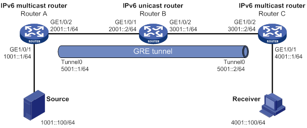
Configuration procedure
1. Assign an IPv6 address and prefix length to each interface, as shown in Figure 82. (Details not shown.)
2. Configure OSPFv3 on the routers. Do not run OSPFv3 on the source-side interface GigabitEthernet 1/0/1 on Router A. (Details not shown.)
3. Configure a GRE tunnel:
# Create an IPv6 GRE tunnel interface Tunnel 0 on Router A.
<RouterA> system-view
[RouterA] interface tunnel 0 mode gre ipv6
# Assign an IPv6 address to interface Tunnel 0 on Router A, and specify its source and destination addresses.
[RouterA-Tunnel0] ipv6 address 5001::1 64
[RouterA-Tunnel0] source 2001::1
[RouterA-Tunnel0] destination 3001::2
[RouterA-Tunnel0] quit
# Create an IPv6 GRE tunnel interface Tunnel 0 on Router C.
<RouterC> system-view
[RouterC] interface tunnel 0 mode gre ipv6
# Assign an IPv6 address to interface Tunnel 0, and specify its source and destination addresses.
[RouterC-Tunnel0] ipv6 address 5001::2 64
[RouterC-Tunnel0] source 3001::2
[RouterC-Tunnel0] destination 2001::1
[RouterC-Tunnel0] quit
4. Enable IPv6 multicast routing, IPv6 PIM-DM, and MLD:
# On Router A, enable IPv6 multicast routing, and enable IPv6 PIM-DM on each interface.
[RouterA] ipv6 multicast routing
[RouterA-mrib6] quit
[RouterA] interface gigabitethernet 1/0/1
[RouterA-GigabitEthernet1/0/1] ipv6 pim dm
[RouterA-GigabitEthernet1/0/1] quit
[RouterA] interface gigabitethernet 1/0/2
[RouterA-GigabitEthernet1/0/2] ipv6 pim dm
[RouterA-GigabitEthernet1/0/2] quit
[RouterA] interface tunnel 0
[RouterA-Tunnel0] ipv6 pim dm
[RouterA-Tunnel0] quit
# On Router C, enable IPv6 multicast routing.
[RouterC] ipv6 multicast routing
[RouterC-mrib6] quit
# Enable MLD on the receiver-side interface (GigabitEthernet 1/0/1).
[RouterC] interface gigabitethernet 1/0/1
[RouterC-GigabitEthernet1/0/1] mld enable
[RouterC-GigabitEthernet1/0/1] quit
# Enable IPv6 PIM-DM on the other interfaces.
[RouterC] interface gigabitethernet 1/0/2
[RouterC-GigabitEthernet1/0/2] ipv6 pim dm
[RouterC-GigabitEthernet1/0/2] quit
[RouterC] interface tunnel 0
[RouterC-Tunnel0] ipv6 pim dm
[RouterC-Tunnel0] quit
5. On Router C, configure a static route with the destination address 1001::/64 and the outgoing interface Tunnel 0.
[RouterC] ipv6 route-static 1001::1 64 tunnel 0
Verifying the configuration
# Send an MLD report from Receiver to join IPv6 multicast group FF1E::101. (Details not shown.)
# Send IPv6 multicast data from Source to IPv6 multicast group FF1E::101. (Details not shown.)
# Display PIM routing entries on Router C.
[RouterC] display ipv6 pim routing-table
Total 1 (*, G) entry; 1 (S, G) entry
(*, FF1E::101)
Protocol: pim-dm, Flag: WC
UpTime: 00:04:25
Upstream interface: NULL
Upstream neighbor: NULL
RPF prime neighbor: NULL
Downstream interface(s) information:
Total number of downstreams: 1
1: GigabitEthernet1/0/1
Protocol: mld, UpTime: 00:04:25, Expires: -
(1001::100, FF1E::101)
Protocol: pim-dm, Flag: ACT
UpTime: 00:06:14
Upstream interface: Tunnel0
Upstream neighbor: FE80::A01:101:1
RPF prime neighbor: FE80::A01:101:1
Downstream interface(s) information:
Total number of downstreams: 1
1: GigabitEthernet1/0/1
Protocol: pim-dm, UpTime: 00:04:25, Expires: -
The output shows the following information:
· Router A is the RPF neighbor of Router C.
· IPv6 multicast data from Router A is delivered over the GRE tunnel to Router C.
IPv6 multicast forwarding over ADVPN tunnel interfaces
Network requirements
As shown in Figure 83:
· An IPv6 ADVPN tunnel is established between each spoke and hub.
· All hubs and spokes support IPv6 multicast. IPv6 PIM-SM runs on them, and NBMA runs on their IPv6 ADVPN tunnel interfaces.
· OSPFv3 runs all hubs and spokes.
Configure the routers so that Spoke 1 can receive IPv6 multicast data from the source.
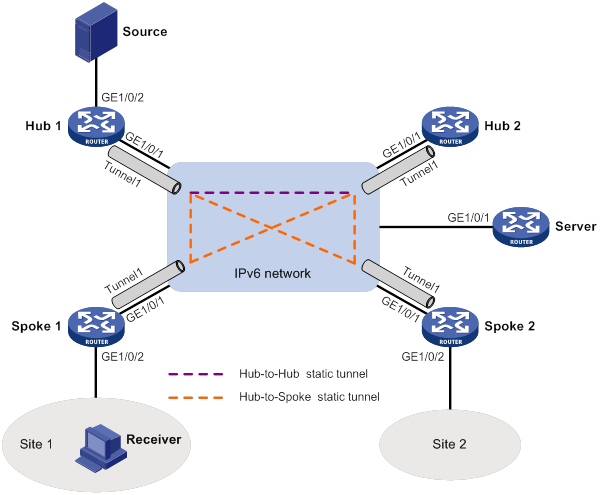
Table 22 Interface and IPv6 address assignment
|
Device |
Interface |
IPv6 address |
Device |
Interface |
IPv6 address |
|
Hub 1 |
Spoke 1 |
||||
|
Hub 1 |
Tunnel1 |
Spoke 1 |
Tunnel1 |
||
|
Hub 1 |
Spoke 1 |
||||
|
Hub 1 |
Spoke 2 |
||||
|
Hub 2 |
Tunnel1 |
Spoke 2 |
Tunnel1 |
||
|
Hub 2 |
Server |
||||
|
Hub 2 |
GE1/0/1 |
1::2/64 |
|
|
|
Configuration procedure
1. Assign an IPv6 address and prefix length to each interface, as shown in Table 22. (Details not shown.)
2. Configure ADVPN:
a. Configure the VAM server:
# Create an ADVPN domain named abc.
<Server> system-view
[Server] vam server advpn-domain abc id 1
# Set the pre-shared key to 123456.
[Server-vam-server-domain-abc] pre-shared-key simple 123456
# Configure the VAM server not to authenticate VAM clients.
[Server-vam-server-domain-abc] authentication-method none
# Enable the VAM server.
[Server-vam-server-domain-abc] server enable
# Create hub group 0.
[Server-vam-server-domain-abc] hub-group 0
# Specify private IPv6 addresses for hubs in hub group 0.
[Server-vam-server-domain-abc-hub-group-0] hub ipv6 private-address 192:168::1
[Server-vam-server-domain-abc-hub-group-0] hub ipv6 private-address 192:168::2
# Specify a private IPv6 address range for spokes in hub group 0.
[Server-vam-server-domain-abc-hub-group-0] spoke ipv6 private-address range 192:168:: 192:168::FFFF:FFFF:FFFF:FFFF
[Server-vam-server-domain-abc-hub-group-0] quit
[Server-vam-server-domain-abc] quit
b. Configure Hub 1:
# Create a VAM client named hub1.
<Hub1> system-view
[Hub1] vam client name Hub1
# Specify ADVPN domain abc for the VAM client.
[Hub1-vam-client-Hub1] advpn-domain abc
# Specify the VAM server.
[Hub1-vam-client-Hub1] server primary ipv6-address 1::11
# Set the pre-shared key to 123456.
[Hub1-vam-client-Hub1] pre-shared-key simple 123456
# Enable the VAM client.
[Hub1-vam-client-Hub1] client enable
c. Configure Hub 2:
# Create a VAM client named hub2.
<Hub2> system-view
[Hub2] vam client name hub2
# Specify ADVPN domain abc for the VAM client.
[Hub2-vam-client-hub2] advpn-domain abc
# Specify the VAM server.
[Hub2-vam-client-hub2] server primary ipv6-address 1::11
# Set the pre-shared key to 123456.
[Hub2-vam-client-hub2] pre-shared-key simple 123456
# Enable the VAM client.
[Hub2-vam-client-hub2] client enable
d. Configure Spoke 1:
# Create a VAM client named Spoke1.
<Spoke1> system-view
[Spoke1] vam client name Spoke1
# Specify ADVPN domain abc for the VAM client.
[Spoke1-vam-client-Spoke1] advpn-domain abc
# Specify the VAM server.
[Spoke1-vam-client-Spoke1] server primary ipv6-address 1::11
# Set the pre-shared key to 123456.
[Spoke1-vam-client-Spoke1] pre-shared-key simple 123456
# Enable the VAM client.
[Spoke1-vam-client-Spoke1] client enable
[Spoke1-vam-client-Spoke1] quit
e. Configure Spoke 2:
# Create a VAM client named Spoke2.
<Spoke2> system-view
[Spoke2] vam client name Spoke2
# Specify ADVPN domain abc for the VAM client.
[Spoke2-vam-client-Spoke2] advpn-domain abc
# Specify the VAM server.
[Spoke2-vam-client-Spoke2] server primary ipv6-address 1::11
# Set the pre-shared key to 123456.
[Spoke2-vam-client-Spoke2] pre-shared-key simple 123456
# Enable the VAM client.
[Spoke2-vam-client-Spoke2] client enable
[Spoke2-vam-client-Spoke2] quit
[Spoke1-vam-client-Spoke1] quit
f. Configure IPv6 ADVPN tunnel interfaces:
# On Hub 1, configure GRE-mode IPv6 ADVPN tunnel interface tunnel1.
[Hub1] interface tunnel 1 mode advpn gre ipv6
[Hub1-Tunnel1] source gigabitethernet 1/0/1
[Hub1-Tunnel1] ipv6 address FE80::1 link-local
[Hub1-Tunnel1] ipv6 address 192:168::1 64
[Hub1-Tunnel1] vam ipv6 client hub1
[Hub1-Tunnel1] quit
# On Hub 2, configure GRE-mode IPv6 ADVPN tunnel interface tunnel1.
[Hub2] interface tunnel 1 mode advpn gre ipv6
[Hub2-Tunnel1] source gigabitethernet 1/0/1
[Hub2-Tunnel1] ipv6 address FE80::2 link-local
[Hub2-Tunnel1] ipv6 address 192:168::2 64
[Hub2-Tunnel1] vam ipv6 client hub1
[Hub2-Tunnel1] quit
# On Spoke 1, configure GRE-mode IPv6 ADVPN tunnel interface tunnel1.
[Spoke1] interface tunnel 1 mode advpn gre ipv6
[Spoke1-Tunnel1] source gigabitethernet 1/0/1
[Spoke1-Tunnel1] ipv6 address FE80::3 link-local
[Spoke1-Tunnel1] ipv6 address 192:168::3/64
[Spoke1-Tunnel1] vam ipv6 client spoke1
[Spoke1-Tunnel1] quit
# On Spoke 2, configure GRE-mode IPv6 ADVPN tunnel interface tunnel1.
[Spoke2] interface tunnel 1 mode advpn gre ipv6
[Spoke2-Tunnel1] source gigabitethernet 1/0/1
[Spoke2-Tunnel1] ipv6 address FE80::4 link-local
[Spoke2-Tunnel1] ipv6 address 192:168::4/64
[Spoke2-Tunnel1] vam ipv6 client spoke2
[Spoke2-Tunnel1] quit
3. Configure OSPFv3:
# On Hub 1, configure OSPFv3.
<Hub1> system-view
[Hub1] ospfv3
[Hub1-ospfv3-1] router-id 0.0.0.1
[Hub1-ospfv3-1] area 0.0.0.0
[Hub1-ospfv3-1-area-0.0.0.0] quit
[Hub1-ospfv3-1] quit
[Hub1] interface loopback 0
[Hub1-LoopBack0] ospfv3 1 area 0.0.0.0
[Hub1-LoopBack0] quit
[Hub1] interface gigabitethernet 1/0/2
[Hub1-GigabitEthernet1/0/2] ospfv3 1 area 0.0.0.0
[Hub1-GigabitEthernet1/0/2] quit
[Hub1] interface tunnel 1
[Hub1-Tunnel1] ospfv3 1 area 0.0.0.0
[Hub1-Tunnel1] ospfv3 network-type p2mp
[Hub1-Tunnel1] quit
# On Hub 2, configure OSPFv3.
<Hub2> system-view
[Hub2] ospfv3
[Hub2-ospfv3-1] router-id 0.0.0.2
[Hub2-ospfv3-1] area 0.0.0.0
[Hub2-ospfv3-1-area-0.0.0.0] quit
[Hub2-ospfv3-1] quit
[Hub2] interface loopback 0
[Hub2-LoopBack0] ospfv3 1 area 0.0.0.0
[Hub2-LoopBack0] quit
[Hub2] interface tunnel 1
[Hub2-Tunnel1] ospfv3 1 area 0.0.0.0
[Hub2-Tunnel1] ospfv3 network-type p2mp
[Hub2-Tunnel1] quit
# On Spoke 1, configure OSPFv3.
<Spoke1> system-view
[Spoke1] ospfv3 1
[Spoke1-ospfv3-1] router-id 0.0.0.3
[Spoke1-ospfv3-1] area 0.0.0.0
[Spoke1-ospfv3-1-area-0.0.0.0] quit
[Spoke1-ospfv3-1] quit
[Spoke1] interface tunnel 1
[Spoke1-Tunnel1] ospfv3 1 area 0.0.0.0
[Spoke1-Tunnel1] ospfv3 network-type p2mp
[Spoke1-Tunnel1] quit
# On Spoke 2, configure OSPFv3.
<Spoke2> system-view
[Spoke2] ospfv3 1
[Spoke2-ospfv3-1] router-id 0.0.0.4
[Spoke2-ospfv3-1] area 0.0.0.0
[Spoke2-ospfv3-1-area-0.0.0.0] quit
[Spoke2-ospfv3-1] quit
[Spoke2] interface tunnel 1
[Spoke2-Tunnel1] ospfv3 1 area 0.0.0.0
[Spoke2-Tunnel1] ospfv3 network-type p2mp
[Spoke2-Tunnel1] quit
[Spoke2] interface gigabitethernet 1/0/2
[Spoke2-GigabitEthernet1/0/2] ospfv3 1 area 0.0.0.0
[Spoke2-GigabitEthernet1/0/2] quit
4. Configure IPv6 multicast:
a. Configure Hub 1:
# Enable IPv6 multicast routing.
<Hub1> system-view
[Hub1] ipv6 multicast routing
[Hub1-mrib6] quit
# Enable IPv6 PIM-SM on Loopback 0 and GigabitEthernet 1/0/2.
[Hub1] interface loopback 0
[Hub1-LoopBack0] ipv6 pim sm
[Hub1-LoopBack0] quit
[Hub1] interface gigabitethernet 1/0/2
[Hub1-GigabitEthernet1/0/2] ipv6 pim sm
[Hub1-GigabitEthernet1/0/2] quit
# Enable IPv6 PIM-SM and NBMA mode on Tunnel interface tunnel1.
[Hub1] interface tunnel 1
[Hub1-Tunnel1] ipv6 pim sm
[Hub1-Tunnel1] ipv6 pim nbma-mode
[Hub1-Tunnel1] quit
# Configure Loopback 0 as a C-BSR and a C-RP.
<Hub1>system-view
[Hub1] ipv6 pim
[Hub1-pim6] c-bsr 44::44
[Hub1-pim6] c-rp 44::44
[Hub1-pim6] quit
b. Configure Hub 2:
# Enable IPv6 multicast routing.
<Hub2> system-view
[Hub2] ipv6 multicast routing
[Hub2-mrib6] quit
# Enable IPv6 PIM-SM on Loopback 0.
[Hub2] interface loopback 0
[Hub2-LoopBack0] ipv6 pim sm
[Hub2-LoopBack0] quit
# Enable IPv6 PIM-SM and NBMA mode on Tunnel interface tunnel1.
[Hub2] interface tunnel 1
[Hub2-Tunnel1] ipv6 pim sm
[Hub2-Tunnel1] ipv6 pim nbma-mode
[Hub2-Tunnel1] quit
# Configure Loopback 0 as a C-BSR and a C-RP.
<Hub2>system-view
[Hub2] ipv6 pim
[Hub2-pim6] c-bsr 55::55
[Hub2-pim6] c-rp 55::55
[Hub2-pim6] quit
c. Configure Spoke 1:
# Enable IPv6 multicast routing.
<Spoke1> system-view
[Spoke1] ipv6 multicast routing
[Spoke1-mrib6] quit
# Enable IPv6 PIM-SM and NBMA mode on Tunnel interface tunnel1.
[Spoke1] interface tunnel 1
[Spoke1-Tunnel1] ipv6 pim sm
[Spoke1-Tunnel1] ipv6 pim nbma-mode
[Spoke1-Tunnel1] quit
# Enable MLD on GigabitEthernet 1/0/2.
[Spoke1] interface gigabitethernet 1/0/2
[Spoke1-GigabitEthernet1/0/2] mld enable
[Spoke1-GigabitEthernet1/0/2] quit
d. Configure Spoke 2:
# Enable IPv6 multicast routing.
<Spoke2> system-view
[Spoke2] ipv6 multicast routing
[Spoke2-mrib6] quit
# Enable IPv6 PIM-SM and NBMA mode on Tunnel interface tunnel1.
[Spoke2] interface tunnel 1
[Spoke2-Tunnel1] ipv6 pim sm
[Spoke2-Tunnel1] ipv6 pim nbma-mode
[Spoke2-Tunnel1] quit
Verifying the configuration
# Send an MLD report from Spoke 1 to join IPv6 multicast group FF0E::1. (Details not shown.)
# Send IPv6 multicast data from the source to the IPv6 multicast group. (Details not shown.)
# Display IPv6 PIM routing entries on Hub 1.
[Hub1]display ipv6 pim routing-table
Total 1 (*, G) entries; 1 (S, G) entries
(*, FF0E::1)
RP: 44::44 (local)
Protocol: pim-sm, Flag: WC
UpTime: 17:02:10
Upstream interface: Register-Tunnel1
Upstream neighbor: NULL
RPF prime neighbor: NULL
Downstream interface information:
Total number of downstream interfaces: 1
1: Tunnel1, FE80::3
Protocol: pim-sm, UpTime: 17:01:23, Expires: 00:02:41
(100::1, FF0E::1)
RP: 44::44 (local)
Protocol: pim-sm, Flag: SPT LOC ACT
UpTime: 00:00:02
Upstream interface: GigabitEthernet1/0/3
Upstream neighbor: NULL
RPF prime neighbor: NULL
Downstream interface information:
Total number of downstream interfacs: 1
1: Tunnel1, FE80::3
Protocol: pim-sm, UpTime: 00:00:02, Expires: 00:03:28
The output show that Tunnel interface tunnel1 (FE80::3) on Spoke 1 will receive the IPv6 multicast data addressed to the IPv6 multicast group FF0E::1 from the source.
Configuring MLD
Overview
Multicast Listener Discovery (MLD) establishes and maintains IPv6 multicast group memberships between a Layer 3 multicast device and the hosts on the directly connected subnet.
MLD has the following versions:
· MLDv1 (defined by RFC 2710), which is derived from IGMPv2.
· MLDv2 (defined by RFC 3810), which is derived from IGMPv3.
MLDv1 and MLDv2 support the ASM model. MLDv2 can directly implement the SSM model, but MLDv1 must work with the MLD SSM mapping feature to implement the SSM model. For more information about the ASM and SSM models, see "Multicast overview."
How MLDv1 works
MLDv1 implements IPv6 multicast listener management based on the query and response mechanism.
Electing the MLD querier
All IPv6 multicast routers that run MLD on the same subnet can monitor MLD listener report messages (often called reports) from hosts. However, only one router can act as the MLD querier to send MLD query messages (often called queries). A querier election mechanism determines which router acts as the MLD querier on the subnet.
1. Initially, every MLD router assumes itself as the querier. Each router sends MLD general query messages (often called general queries) to all hosts and routers on the local subnet. The destination address of the general queries is FF02::1.
2. After receiving a general query, every MLD router compares the source IPv6 address of the query with its own link-local interface address. The router with the lowest IPv6 address wins the querier election and becomes the querier. All the other routers become non-queriers.
3. All the non-queriers start a timer called the "other querier present timer." If a router receives an MLD query from the querier before the timer expires, it resets this timer. Otherwise, it considers that the querier has timed out. In this case, the router initiates a new querier election process.
Joining an IPv6 multicast group
Figure 84 MLD queries and reports

As shown in Figure 84, Host B and Host C want to receive the IPv6 multicast data addressed to IPv6 multicast group G1. Host A wants to receive the IPv6 multicast data addressed to G2. The following process describes how the hosts join the IPv6 multicast groups and how the MLD querier (Router B in Figure 84) maintains the IPv6 multicast group memberships:
1. The hosts send unsolicited MLD reports to the IPv6 multicast groups they want to join without having to wait for the MLD queries.
2. The MLD querier periodically multicasts MLD queries (with the destination address FF02::1) to all hosts and routers on the local subnet.
3. After receiving a query, the host whose report delay timer expires first sends an MLD report to the IPv6 multicast group G1 to announce its membership for G1. In this example, Host B sends the report. After hearing the report from Host B, Host C, which is on the same subnet as Host B, suppresses its own report for G1.
Because the MLD routers already know that G1 has a minimum of one member, other members do not need to report their memberships. This mechanism, known as the host MLD report suppression, helps reduce traffic on the local subnet.
4. At the same time, because Host A is interested in G2, it sends a report to the IPv6 multicast group G2.
5. Through the query/report process, the MLD routers determine that G1 and G2 have members on the local subnet. The IPv6 multicast routing protocol (for example, IPv6 PIM) that is running on the routers generates (*, G1) and (*, G2) multicast forwarding entries. These entries are the basis for subsequent IPv6 multicast forwarding. The asterisk (*) represents any IPv6 multicast source.
6. When the IPv6 multicast data addressed to G1 or G2 reaches an MLD router, the router looks up the IPv6 multicast forwarding table. Based on the (*, G1) and (*, G2) entries, the router forwards the IPv6 multicast data to the local subnet. Then, the receivers on the subnet receive the data.
Leaving an IPv6 multicast group
When a host is leaving an IPv6 multicast group, the following process occurs:
1. The host sends an MLD done message to all IPv6 multicast routers on the local subnet. The destination address of done messages is FF02::2.
2. After receiving the MLD done message, the querier sends a configurable number of multicast-address-specific queries to the group that the host is leaving. The IPv6 multicast addresses queried include both the destination address field and the group address field of the message.
3. One of the remaining members (if any on the subnet) in the group sends a report within the time of the maximum response time advertised in the multicast-address-specific queries.
4. If the querier receives a report for the group within the maximum response time, it maintains the memberships of the IPv6 multicast group. Otherwise, the querier assumes that no hosts on the subnet are interested in IPv6 multicast traffic addressed to that group and stops maintaining the memberships of the group.
MLDv2 enhancements
MLDv2 is based on and backwards-compatible with MLDv1. MLDv2 provides hosts with enhanced control capabilities and enhances the MLD state.
Enhancements in control capability of hosts
MLDv2 has introduced IPv6 multicast source filtering modes (Include and Exclude). These modes allow a host to receive or reject multicast data from the specified IPv6 multicast sources. When a host joins an IPv6 multicast group, one of the following occurs:
· If the host expects IPv6 multicast data from specific IPv6 multicast sources like S1, S2, …, it sends a report with Filter-Mode denoted as "Include Sources (S1, S2, …)."
· If the host does not expect IPv6 multicast data from specific IPv6 multicast sources like S1, S2, …, it sends a report with Filter-Mode denoted as "Exclude Sources (S1, S2, …)."
As shown in Figure 85, the network has two IPv6 multicast sources, Source 1 (S1) and Source 2 (S2). Both of the sources can send IPv6 multicast data to IPv6 multicast group G. Host B wants to receive IPv6 multicast data addressed to G from Source 1 but not from Source 2.
Figure 85 Flow paths of multicast-address-and-source-specific multicast traffic
In MLDv1, Host B cannot select IPv6 multicast sources when it joins IPv6 multicast group G. The IPv6 multicast streams from both Source 1 and Source 2 flow to Host B whether it needs them or not.
In MLDv2, Host B can explicitly express its interest in IPv6 multicast data destined to G from Source 1 but not from Source 2. Then, Host B receives only IPv6 multicast data from Source 1.
Enhancement in MLD state
A multicast router that is running MLDv2 maintains the multicast address state for each multicast address on each attached subnet. The multicast address state consists of the following information:
· Filter mode—Router keeps tracing the Include or Exclude state.
· List of sources—Router keeps tracing the newly added or deleted IPv6 multicast source.
· Timers—Filter timers, which include the time that the router waits before switching to the Include mode after an IPv6 multicast address times out, and source timers for source recording.
MLD SSM mapping
An MLDv2 host can explicitly specify multicast sources in its MLDv2 reports. From the reports, the MLD router can obtain the multicast source addresses and directly provide the SSM service. However, an MLDv1 host cannot specify multicast sources in its MLDv1 reports.
The MLD SSM mapping feature enables the MLD router to provide SSM support for MLDv1 receiver host. The router translates (*, G) in MLDv1 reports into (G, INCLUDE, (S1, S2...)) based on the configured MLD SSM mappings.
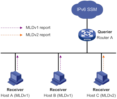
As shown in Figure 86, Host A and Host B on the IPv6 SSM network run MLDv1, and Host C runs MLDv2. To provide the SSM service for Host A and Host B, you must configure the MLD SSM mapping feature on Router A.
After MLD SSM mappings are configured, Router A checks the IPv6 multicast group address G carried in the message, and performs the following operations:
· If G is not in the IPv6 SSM group range, Router A provides the ASM service.
· If G is in the IPv6 SSM group range but does not match any MLD SSM mapping, Router A drops the report.
· If G is in the IPv6 SSM group range and matches MLD SSM mappings, Router A translates (*, G) in the report to (G, INCLUDE, (S1, S2...)) to provide SSM services.
|
|
NOTE: The MLD SSM mapping feature does not process MLDv2 reports. |
For more information about the IPv6 SSM group ranges, see "Configuring IPv6 PIM."
MLD proxying
As shown in Figure 87, in a simple tree-shaped topology, it is not necessary to configure IPv6 multicast routing protocols, such as IPv6 PIM, on edge devices. Instead, you can configure MLD proxying on these devices. With MLD proxying configured, the edge device acts as an MLD proxy:
· For the upstream MLD querier, the MLD proxy device acts as a host.
· For the downstream receiver hosts, the MLD proxy device acts as an MLD querier.

The following interfaces are defined in MLD proxying:
· Host interface—An interface that is in the direction toward the root of the multicast forwarding tree. A host interface acts as a receiver host that is running MLD. MLD proxying must be enabled on this interface. This interface is also called the "proxy interface."
· Router interface—An interface that is in the direction toward the leaf of the multicast forwarding tree. A router interface acts as a router that is running MLD. MLD must be configured on this interface.
An MLD proxy device maintains a group membership database, which stores the group memberships on all the router interfaces. The host interfaces and router interfaces perform actions based on this membership database.
· The host interfaces respond to queries according to the membership database or sends join/done messages when the database changes.
· The router interfaces participate in the querier election, send queries, and maintain memberships based on received MLD reports.
MLD support for VPNs
MLD maintains group memberships on a per-interface basis. After receiving an MLD message on an interface, MLD processes the packet within the VPN to which the interface belongs. MLD only communicates with other multicast protocols within the same VPN instance.
Protocols and standards
· RFC 2710, Multicast Listener Discovery (MLD) for IPv6
· RFC 3810, Multicast Listener Discovery Version 2 (MLDv2) for IPv6
Feature and hardware compatibility
The following matrix shows the feature and hardware compatibility:
|
Hardware |
MLD compatibility |
|
MSR810/810-W/810-W-DB/810-LM/810-W-LM/810-10-PoE/810-LM-HK/810-W-LM-HK/810-LMS/810-LUS |
No |
|
MSR2600-6-X1/2600-10-X1 |
Yes |
|
MSR 2630 |
Yes |
|
MSR3600-28/3600-51 |
Yes |
|
MSR3600-28-SI/3600-51-SI |
No |
|
MSR3610-X1/3610-X1-DP/3610-X1-DC/3610-X1-DP-DC |
Yes |
|
MSR 3610/3620/3620-DP/3640/3660 |
Yes |
|
MSR5620/5660/5680 |
Yes |
|
Hardware |
MLD compatibility |
|
MSR810-LM-GL |
Yes |
|
MSR810-W-LM-GL |
Yes |
|
MSR830-6EI-GL |
Yes |
|
MSR830-10EI-GL |
Yes |
|
MSR830-6HI-GL |
Yes |
|
MSR830-10HI-GL |
Yes |
|
MSR2600-6-X1-GL |
Yes |
|
MSR3600-28-SI-GL |
No |
MLD configuration task list
|
Tasks at a glance |
|
Configuring basic MLD features: · (Required.) Enabling MLD · (Optional.) Specifying an MLD version · (Optional.) Configuring a static group member · (Optional.) Configuring an IPv6 multicast group policy |
|
(Optional.) Configuring MLD query and response parameters (Optional.) Enabling fast-leave processing |
|
(Optional.) Configuring MLD SSM mappings |
|
· (Optional.) Enabling MLD proxying · (Optional.) Enabling IPv6 multicast forwarding on a non-querier interface · (Optional.) Configuring IPv6 multicast load splitting on an MLD proxy |
|
(Optional.) Enabling MLD NSR |
Configuring basic MLD features
Before you configure basic MLD features, complete the following tasks:
· Enable IPv6 forwarding and configure an IPv6 unicast routing protocol so that all devices can interoperate at the network layer.
· Configure IPv6 PIM.
· Determine the MLD version.
· Determine the IPv6 multicast group address and IPv6 multicast source address for static group member configuration.
· Determine the ACL to be used in the IPv6 multicast group policy.
Enabling MLD
Perform this task on interfaces where IPv6 multicast group memberships are created and maintained.
To enable MLD:
|
Step |
Command |
Remarks |
|
1. Enter system view. |
system-view |
N/A |
|
2. Enable IPv6 multicast routing and enter IPv6 MRIB view. |
ipv6 multicast routing [ vpn-instance vpn-instance-name ] |
By default, IPv6 multicast routing is disabled. |
|
3. Return to system view. |
quit |
N/A |
|
4. Enter interface view. |
interface interface-type interface-number |
N/A |
|
5. Enable MLD. |
mld enable |
By default, MLD is disabled. |
Specifying an MLD version
For MLD to operate correctly, specify the same MLD version for all routers on the same subnet.
To specify an MLD version:
|
Step |
Command |
Remarks |
|
1. Enter system view. |
system-view |
N/A |
|
2. Enter interface view. |
interface interface-type interface-number |
N/A |
|
3. Specify an MLD version on the interface. |
mld version version-number |
The default setting is 1. |
Configuring a static group member
You can configure an interface as a static member of an IPv6 multicast group. Then, the interface can always receive IPv6 multicast data for the group.
A static group member does not respond to MLD queries. When you complete or cancel this configuration on an interface, the interface does not send an unsolicited MLD report or done message.
Configuration guidelines
The interface to be configured as a static member of an IPv6 multicast group has the following restrictions:
· If the interface is MLD and IPv6 PIM-SM enabled, it must be an IPv6 PIM-SM DR.
· If the interface is MLD enabled but not IPv6 PIM-SM enabled, it must be an MLD querier.
For more information about IPv6 PIM-SM and DR, see "Configuring IPv6 PIM."
Configuration procedure
To configure a static group member:
|
Step |
Command |
Remarks |
|
1. Enter system view. |
system-view |
N/A |
|
2. Enter interface view. |
interface interface-type interface-number |
N/A |
|
3. Configure a static group member. |
mld static-group ipv6-group-address [ source ipv6-source-address ] |
By default, the interface is not a static group member of any IPv6 multicast groups. |
Configuring an IPv6 multicast group policy
This feature enables an interface to filter MLD reports by using an ACL that specifies IPv6 multicast groups and the optional sources. It is used to control the IPv6 multicast groups that the hosts attached to an interface can join.
This configuration does not take effect on static group members.
To configure an IPv6 multicast group policy:
|
Step |
Command |
Remarks |
|
1. Enter system view. |
system-view |
N/A |
|
2. Enter interface view. |
interface interface-type interface-number |
N/A |
|
3. Configure an IPv6 multicast group policy on the interface. |
mld group-policy ipv6-acl-number [ version-number ] |
By default, no IPv6 multicast group polices exist on an interface, and hosts attached to the interface can join any IPv6 multicast groups. |
Adjusting MLD performance
Before adjusting MLD performance, complete the following tasks:
· Enable IPv6 forwarding and configure an IPv6 unicast routing protocol so that all devices can interoperate at the network layer.
· Configure basic MLD features.
Configuring MLD query and response parameters
The following are MLD query and response parameters:
· MLD querier's robustness variable—Number of times for retransmitting MLD queries in case of packet loss. A higher robustness variable makes the MLD querier more robust, but increases the timeout time for IPv6 multicast groups.
· MLD startup query interval—Interval at which an MLD querier sends MLD general queries at startup.
· MLD startup query count—Number of MLD general queries that an MLD querier sends at startup.
· MLD general query interval—Interval at which an MLD querier sends MLD general queries to check for IPv6 multicast group members on the network.
· MLD last listener query interval—In MLDv1, it sets the interval at which a querier sends multicast-address-specific queries after receiving a done message. In MLDv2, it sets the interval at which a querier sends multicast-address-and-source-specific queries after receiving a report that changes IPv6 multicast source and group mappings.
· MLD last listener query count—In MLDv1, it sets the number of multicast-address-specific queries that the querier sends after receiving a done message. In MLDv2, it sets the number of multicast-address-and-source-specific queries that the querier sends after receiving a report that changes IPv6 multicast group and source mappings.
· MLD maximum response time—Maximum time before a receiver responds with a report to an MLD general query. This per-group timer is initialized to a random value in the range of 0 to the maximum response time specified in the MLD query. When the timer value decreases to 0, the receiver sends an MLD report to the group.
· MLD other querier present timer—Lifetime for an MLD querier after a non-querier receives an MLD general query. If the non-querier does not receive a new query when this timer expires, the non-querier considers that the querier has failed and starts a new querier election.
Configuration guidelines
When you configure the MLD query and response parameters, follow these restrictions and guidelines:
· You can configure the MLD query and response parameters globally for all interfaces in MLD view or for an interface in interface view. For an interface, the interface-specific configuration takes priority over the global configuration.
· To avoid frequent MLD querier changes, set the MLD other querier present timer greater than the MLD general query interval. In addition, configure the same MLD other querier present timer for all MLD routers on the same subnet.
· To speed up the response to MLD queries and avoid simultaneous timer expirations that cause MLD report traffic bursts, you must set an appropriate maximum response time.
? For MLD general queries, the maximum response time is set by the max-response-time command.
? For MLD multicast-address-specific queries or MLD multicast-address-and-source-specific queries, the maximum response time equals the MLD last listener query interval.
Configuring the MLD query and response parameters globally
|
Step |
Command |
Remarks |
|
1. Enter system view. |
N/A |
|
|
2. Enter MLD view. |
N/A |
|
|
3. Set the MLD querier's robustness variable. |
By default, the MLD querier's robustness variable is 2. |
|
|
4. Set the MLD startup query interval. |
By default, the MLD startup query interval equals one quarter of the MLD general query interval. |
|
|
5. Set the MLD startup query count. |
By default, the MLD startup query count equals the MLD querier's robustness variable. |
|
|
6. Set the MLD general query interval. |
By default, the MLD general query interval is 125 seconds. |
|
|
7. Set the MLD last listener query interval. |
By default, the MLD last listener query interval is 1 second. |
|
|
8. Set the MLD last listener query count. |
By default, the MLD last listener query count equals the MLD querier's robustness variable. |
|
|
9. Set the maximum response time for MLD general queries. |
By default, the maximum response time for MLD general queries is 10 seconds. |
|
|
10. Set the MLD other querier present timer. |
By default, the MLD other querier present
timer is calculated by using the following formula: |
Configuring the MLD query and response parameters on an interface
|
Step |
Command |
Remarks |
|
1. Enter system view. |
N/A |
|
|
2. Enter interface view. |
N/A |
|
|
3. Set the MLD querier's robustness variable. |
By default, the MLD querier's robustness variable is 2. |
|
|
4. Set the MLD startup query interval. |
By default, the MLD startup query interval equals one quarter of the MLD general query interval. |
|
|
5. Set the MLD startup query count. |
By default, the MLD startup query count equals the MLD querier's robustness variable. |
|
|
6. Set the MLD general query interval. |
By default, the MLD general query interval is 125 seconds. |
|
|
7. Set the MLD last listener query interval. |
By default, the MLD last listener query interval is 1 second. |
|
|
8. Set the MLD last listener query count. |
By default, the MLD last listener query count equals the MLD querier's robustness variable. |
|
|
9. Set the maximum response time for MLD general queries. |
By default, the maximum response time for MLD general queries is 10 seconds. |
|
|
10. Set the MLD other querier present timer. |
By default, the MLD other querier present
timer is calculated by using the following formula: |
Enabling fast-leave processing
This feature enables an MLD querier to send leave notifications to the upstream without sending multicast-address-specific or multicast-address-and-source-specific queries after receiving a done message. Use this feature to reduce leave latency and to preserve the network bandwidth.
To enable fast-leave processing:
|
Step |
Command |
Remarks |
|
1. Enter system view. |
system-view |
N/A |
|
2. Enter interface view. |
interface interface-type interface-number |
N/A |
|
3. Enable fast-leave processing. |
mld fast-leave [ group-policy ipv6-acl-number ] |
By default, fast-leave processing is disabled. |
Configuring MLD SSM mappings
This feature enables the device to provide SSM services for MLDv1 hosts.
This feature does not process MLDv2 messages. As a best practice, enable MLDv2 on the receiver-side interface to avoid MLDv2 hosts failing to join IPv6 multicast groups.
Configuration prerequisites
Before you configure MLD SSM mappings, complete the following tasks:
· Configure an IPv6 unicast routing protocol so that all devices in the domain can interoperate at the network layer.
· Configure basic MLD features.
Configuration procedure
To configure an MLD SSM mapping:
|
Step |
Command |
Remarks |
|
1. Enter system view. |
system-view |
N/A |
|
2. Enter MLD view. |
N/A |
|
|
3. Configure an MLD SSM mapping. |
ssm-mapping ipv6-source-address ipv6-acl-number |
By default, no MLD SSM mappings exist. |
Configuring MLD proxying
This section describes how to configure MLD proxying.
Configuration prerequisites
Before you configure the MLD proxying feature, complete the following tasks:
1. Configure any IPv6 unicast routing protocol so that all devices in the domain can interoperate at the network layer.
2. Determine the router interfaces and host interface based on the network topology.
3. Enable MLD on the router interfaces.
Enabling MLD proxying
When you enable MLD proxying, follow these restrictions and guidelines:
· You must enable MLD proxying on the receiver-side interfaces.
· On an interface enabled with MLD proxying, only the mld version command takes effect and other MLD commands do not take effect.
· If you enable both MLD proxying and an IPv6 multicast routing protocol on the same device, the IPv6 multicast routing protocol does not take effect.
To enable MLD proxying:
|
Step |
Command |
Remarks |
|
1. Enter system view. |
system-view |
N/A |
|
2. Enable IPv6 multicast routing and enter IPv6 MRIB view. |
By default, IPv6 multicast routing is disabled. |
|
|
3. Return to system view. |
quit |
N/A |
|
4. Enter interface view. |
interface interface-type interface-number |
N/A |
|
5. Enable MLD proxying. |
By default, MLD proxying is disabled. |
Enabling IPv6 multicast forwarding on a non-querier interface
Typically, only MLD queriers can forward IPv6 multicast traffic and non-queriers cannot. This prevents IPv6 multicast data from being repeatedly forwarded. If a router interface on the MLD proxy failed the querier election, enable IPv6 multicast forwarding on the interface to forward IPv6 multicast data to downstream receivers.
Configuration restrictions and guidelines
On a shared-media network, multiple MLD proxy devices might exist. If a router interface of an MLD proxy device acts as the querier, do not enable IPv6 multicast forwarding on any router interfaces of the remaining proxy devices. If you enable IPv6 multicast forwarding on a router interface, duplicate multicast traffic might be received on the shared-media network.
Configuration procedure
To enable IPv6 multicast forwarding on a non-querier interface:
|
Step |
Command |
Remarks |
|
1. Enter system view. |
system-view |
N/A |
|
2. Enter interface view. |
N/A |
|
|
3. Enable multicast forwarding on the interface. |
By default, IPv6 multicast forwarding is disabled for a non-querier interface. |
Configuring IPv6 multicast load splitting on an MLD proxy
This feature enables all proxy interfaces on an MLD proxy device to share IPv6 multicast traffic on a per-group basis.
To enable IPv6 multicast load splitting on an MLD proxy:
|
Step |
Command |
Remarks |
|
1. Enter system view. |
system-view |
N/A |
|
2. Enter MLD view. |
N/A |
|
|
3. Enable IPv6 multicast load splitting on an MLD proxy. |
proxy multipath |
By default, IPv6 multicast load splitting is disabled on an MLD proxy, and only the proxy interface with the highest IP address forwards IPv6 multicast data. |
Enabling MLD NSR
The following matrix shows the feature and hardware compatibility:
|
Hardware |
MLD NSR compatibility |
|
MSR810/810-W/810-W-DB/810-LM/810-W-LM/810-10-PoE/810-LM-HK/810-W-LM-HK/810-LMS/810-LUS |
No |
|
MSR2600-6-X1/2600-10-X1 |
No |
|
MSR 2630 |
Yes |
|
MSR3600-28/3600-51 |
Yes |
|
MSR3600-28-SI/3600-51-SI |
No |
|
MSR3610-X1/3610-X1-DP/3610-X1-DC/3610-X1-DP-DC |
Yes |
|
MSR 3610/3620/3620-DP/3640/3660 |
Yes |
|
MSR5620/5660/5680 |
Yes |
|
Hardware |
MLD NSR compatibility |
|
MSR810-LM-GL |
No |
|
MSR810-W-LM-GL |
No |
|
MSR830-6EI-GL |
No |
|
MSR830-10EI-GL |
No |
|
MSR830-6HI-GL |
No |
|
MSR830-10HI-GL |
No |
|
MSR2600-6-X1-GL |
No |
|
MSR3600-28-SI-GL |
No |
This feature backs up information about MLD interfaces and MLD multicast groups to the standby process. The device recovers the information without cooperation of other devices when an active/standby switchover occurs. Use this feature to prevent an active/standby switchover from affecting the IPv6 multicast service.
To enable MLD NSR:
|
Step |
Command |
Remarks |
|
1. Enter system view. |
system-view |
N/A |
|
2. Enable MLD NSR. |
mld non-stop-routing |
By default, MLD NSR is disabled. |
Displaying and maintaining MLD
|
|
CAUTION: The reset mld group command might cause IPv6 multicast data transmission failures. |
Execute display commands in any view and reset commands in user view.
|
Task |
Command |
|
Display information about MLD multicast groups. |
display mld [ vpn-instance vpn-instance-name ] group [ ipv6-group-address | interface interface-type interface-number ] [ static | verbose ] |
|
Display MLD information for interfaces. |
display mld [ vpn-instance vpn-instance-name ] interface [ interface-type interface-number ] [ proxy ] [ verbose ] |
|
Display IPv6 multicast routing entries maintained by the MLD proxy. |
|
|
Display information about the MLD proxy routing table. |
|
|
Display MLD SSM mappings. |
display mld [ vpn-instance vpn-instance-name ] ssm-mapping ipv6-group-address |
|
Clear dynamic MLD multicast group entries. |
reset mld [ vpn-instance vpn-instance-name ] group { all | interface interface-type interface-number { all | ipv6-group-address [ prefix-length ] [ ipv6-source-address [ prefix-length ] ] } } |
MLD configuration examples
Basic MLD features configuration examples
Network requirements
As shown in Figure 88:
· OSPFv3 and IPv6 PIM-DM run on the network.
· VOD streams are sent to receiver hosts in multicast. Receiver hosts of different organizations form stub networks N1 and N2. Host A and Host C are multicast receiver hosts in N1 and N2, respectively.
· MLDv1 runs between Router A and N1, and between the other two routers (Router B and Router C) and N2.
· Router A acts as the MLD querier in N1. Router B acts as the MLD querier in N2 because it has a lower IPv6 address.
Configure the routers to meet the following requirements:
· The hosts in N1 can only join IPv6 multicast group FF1E::101.
· The hosts in N2 can join any IPv6 multicast groups.
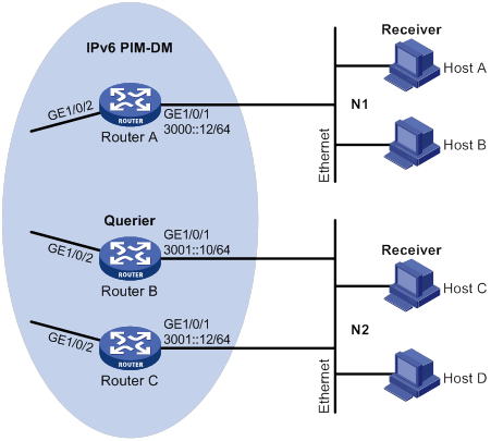
Configuration procedure
1. Assign an IPv6 address and prefix length to each interface, as shown in Figure 88. (Details not shown.)
2. Configure OSPFv3 on the routers in the IPv6 PIM-DM domain. (Details not shown.)
3. Enable the IPv6 multicast routing, MLD, and IPv6 PIM-DM:
# On Router A, enable IPv6 multicast routing.
<RouterA> system-view
[RouterA] ipv6 multicast routing
[RouterA-mrib6] quit
# Enable MLD on GigabitEthernet 1/0/1.
[RouterA] interface gigabitethernet 1/0/1
[RouterA-GigabitEthernet1/0/1] mld enable
[RouterA-GigabitEthernet1/0/1] quit
# Enable IPv6 PIM-DM on GigabitEthernet 1/0/2.
[RouterA] interface gigabitethernet 1/0/2
[RouterA-GigabitEthernet1/0/2] ipv6 pim dm
[RouterA-GigabitEthernet1/0/2] quit
# On Router B, enable IPv6 multicast routing.
<RouterB> system-view
[RouterB] ipv6 multicast routing
[RouterB-mrib6] quit
# Enable MLD on GigabitEthernet 1/0/1.
[RouterB] interface gigabitethernet 1/0/1
[RouterB-GigabitEthernet1/0/1] mld enable
[RouterB-GigabitEthernet1/0/1] quit
# Enable IPv6 PIM-DM on GigabitEthernet 1/0/2.
[RouterB] interface gigabitethernet 1/0/2
[RouterB-GigabitEthernet1/0/2] ipv6 pim dm
[RouterB-GigabitEthernet1/0/2] quit
# On Router C, enable IPv6 multicast routing.
<RouterC> system-view
[RouterC] ipv6 multicast routing
[RouterC-mrib6] quit
# Enable MLD on GigabitEthernet 1/0/1.
[RouterC] interface gigabitethernet 1/0/1
[RouterC-GigabitEthernet1/0/1] mld enable
[RouterC-GigabitEthernet1/0/1] quit
# Enable IPv6 PIM-DM on GigabitEthernet 1/0/2.
[RouterC] interface gigabitethernet 1/0/2
[RouterC-GigabitEthernet1/0/2] ipv6 pim dm
[RouterC-GigabitEthernet1/0/2] quit
4. Configure an IPv6 multicast group policy on Router A so that hosts connected to GigabitEthernet 1/0/1 can join only IPv6 multicast group FF1E::101.
[RouterA] acl ipv6 basic 2001
[RouterA-acl-ipv6-basic-2001] rule permit source ff1e::101 128
[RouterA-acl-ipv6-basic-2001] quit
[RouterA] interface gigabitethernet 1/0/1
[RouterA-GigabitEthernet1/0/1] mld group-policy 2001
[RouterA-GigabitEthernet1/0/1] quit
Verifying the configuration
# Display MLD information for GigabitEthernet 1/0/1 on Router B.
[RouterB] display mld interface gigabitethernet 1/0/1
GigabitEthernet1/0/1(FE80::200:5EFF:FE66:5100):
MLD is enabled.
MLD version: 1
Query interval for MLD: 125s
Other querier present time for MLD: 255s
Maximum query response time for MLD: 10s
Querier for MLD: FE80::200:5EFF:FE66:5100 (this router)
MLD groups reported in total: 1
MLD SSM mapping configuration example
Network requirements
As shown in Figure 89:
· OSPFv3 runs on the network.
· The IPv6 PIM-SM domain uses the SSM model for IPv6 multicast delivery. The IPv6 SSM group range is FF3E::/64.
· MLDv2 runs on GigabitEthernet 1/0/1 of Router D. The receiver host runs MLDv1, and does not support MLDv2. The receiver host cannot specify multicast sources in its membership reports.
· Source 1, Source 2, and Source 3 send IPv6 multicast packets to multicast groups in the IPv6 SSM group range.
Configure the MLD SSM mapping feature on Router D so that the receiver host will receive IPv6 multicast data only from Source 1 and Source 3.

Table 23 Interface and IPv6 address assignment
|
Device |
Interface |
IPv6 address |
Device |
Interface |
IPv6 address |
|
— |
— |
||||
|
— |
— |
||||
|
Router A |
Router C |
||||
|
Router A |
Router C |
||||
|
Router B |
Router D |
||||
|
Router B |
Router D |
Configuration procedure
1. Assign an IPv6 address and prefix length to each interface, as shown in Table 23. (Details not shown.)
2. Configure OSPFv3 on the routers in the IPv6 PIM-SM domain. (Details not shown.)
3. Enable IPv6 multicast routing, IPv6 PIM-SM, and MLD:
# On Router D, enable IPv6 multicast routing.
[RouterD] ipv6 multicast routing
[RouterD-mrib6] quit
# Enable MLDv2 on the receiver-side interface (GigabitEthernet 1/0/1).
[RouterD] interface gigabitethernet 1/0/1
[RouterD-GigabitEthernet1/0/1] mld enable
[RouterD-GigabitEthernet1/0/1] mld version 2
[RouterD-GigabitEthernet1/0/1] quit
# Enable IPv6 PIM-SM on the other interfaces.
[RouterD] interface gigabitethernet 1/0/2
[RouterD-GigabitEthernet1/0/2] ipv6 pim sm
[RouterD-GigabitEthernet1/0/2] quit
[RouterD] interface gigabitethernet 1/0/3
[RouterD-GigabitEthernet1/0/3] ipv6 pim sm
[RouterD-GigabitEthernet1/0/3] quit
# On Router A, enable IPv6 multicast routing.
[RouterA] ipv6 multicast routing
[RouterA-mrib6] quit
# Enable IPv6 PIM-SM on each interface.
[RouterA] interface gigabitethernet 1/0/1
[RouterA-GigabitEthernet1/0/1] ipv6 pim sm
[RouterA-GigabitEthernet1/0/1] quit
[RouterA] interface gigabitethernet 1/0/2
[RouterA-GigabitEthernet1/0/2] ipv6 pim sm
[RouterA-GigabitEthernet1/0/2] quit
[RouterA] interface gigabitethernet 1/0/3
[RouterA-GigabitEthernet1/0/3] ipv6 pim sm
[RouterA-GigabitEthernet1/0/3] quit
# Configure Router B and Router C in the same way Router A is configured. (Details not shown.)
4. Configure the IPv6 SSM group range:
# On Router D, specify FF3E::/64 as the IPv6 SSM group range.
[RouterD] acl ipv6 basic 2000
[RouterD-acl-ipv6-basic-2000] rule permit source ff3e:: 64
[RouterD-acl-ipv6-basic-2000] quit
[RouterD] ipv6 pim
[RouterD-pim6] ssm-policy 2000
[RouterD-pim6] quit
# Configure Router A, Router B, and Router C in the same way Router D is configured. (Details not shown.)
5. Configure MLD SSM mappings on Router D.
[RouterD] mld
[RouterD-mld] ssm-mapping 1001::1 2000
[RouterD-mld] ssm-mapping 3001::1 2000
[RouterD-mld] quit
Verifying the configuration
# Display MLD SSM mappings for IPv6 multicast group FF3E::101 on Router D.
[RouterD] display mld ssm-mapping ff3e::101
Group: FF3E::101
Source list:
1001::1
3001::1
# Display information about MLD multicast groups that hosts have dynamically joined on Router D.
<RouterD> display mld group ff3e::101 verbose
GigabitEthernet1/0/1(FE80::101):
MLD groups reported in total: 1
Group: FF3E::101
Uptime: 00:01:46
Exclude expires: 00:04:16
Mapping expires: 00:02:16
Last reporter: FE80::10
Last-listener-query-counter: 0
Last-listener-query-timer-expiry: Off
Mapping last-listener-query-counter: 0
Mapping last-listener-query-timer-expiry: Off
Group mode: Exclude
Version1-host-present-timer-expiry: Off
Source list (sources in total: 1):
Source: 1001::1
Uptime: 00:00:09
V2 expires: 00:04:11
Mapping expires: 00:02:16
Last-listener-query-counter: 0
Last-listener-query-timer-expiry: Off
Source: 3001::1
Uptime: 00:00:09
V2 expires: 00:04:11
Mapping expires: 00:02:16
Last-listener-query-counter: 0
Last-listener-query-timer-expiry: Off
# Display IPv6 PIM routing entries on Router D.
[RouterD] display ipv6 pim routing-table
Total 0 (*, G) entry; 2 (S, G) entry
(1001::1, FF3E::101)
Protocol: pim-ssm, Flag:
UpTime: 00:13:25
Upstream interface: GigabitEthernet1/0/3
Upstream neighbor: 1003::1
RPF prime neighbor: 1003::1
Downstream interface(s) information:
Total number of downstreams: 1
1: GigabitEthernet1/0/1
Protocol: mld, UpTime: 00:13:25, Expires: -
(3001::1, FF3E::101)
Protocol: pim-ssm, Flag:
UpTime: 00:13:25
Upstream interface: GigabitEthernet1/0/2
Upstream neighbor: 3002::1
RPF prime neighbor: 3002::1
Downstream interface(s) information:
Total number of downstreams: 1
1: GigabitEthernet1/0/1
Protocol: mld, UpTime: 00:13:25, Expires: -
MLD proxying configuration example
Network requirements
As shown in Figure 90:
· IPv6 PIM-DM runs on the core network.
· Host A and Host C on the stub network receive VOD information sent to IPv6 multicast group FF3E::101.
Configure the MLD proxying feature on Router B so that Router B can maintain group memberships and forward IPv6 multicast traffic without running IPv6 PIM-DM.
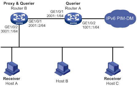
Configuration procedure
1. Assign an IPv6 address and prefix length to each interface, as shown in Figure 90. (Details not shown.)
2. Configure IPv6 unicast routes to make sure devices can reach other. (Details not shown.)
3. Enable IPv6 multicast routing, IPv6 PIM-DM, MLD, and MLD proxying:
# On Router A, enable IPv6 multicast routing.
<RouterA> system-view
[RouterA] ipv6 multicast routing
[RouterA-mrib6] quit
# Enable IPv6 PIM-DM on GigabitEthernet 1/0/2.
[RouterA] interface gigabitethernet 1/0/2
[RouterA-GigabitEthernet1/0/2] ipv6 pim dm
[RouterA-GigabitEthernet1/0/2] quit
# Enable MLD on GigabitEthernet 1/0/1.
[RouterA] interface gigabitethernet 1/0/1
[RouterA-GigabitEthernet1/0/1] mld enable
[RouterA-GigabitEthernet1/0/1] quit
# On Router B, enable IPv6 multicast routing.
<RouterB> system-view
[RouterB] ipv6 multicast routing
[RouterB-mrib6] quit
# Enable MLD proxying on GigabitEthernet 1/0/1.
[RouterB] interface gigabitethernet 1/0/1
[RouterB-GigabitEthernet1/0/1] mld proxy enable
[RouterB-GigabitEthernet1/0/1] quit
# Enable MLD on GigabitEthernet 1/0/2.
[RouterB] interface gigabitethernet 1/0/2
[RouterB-GigabitEthernet1/0/2] mld enable
[RouterB-GigabitEthernet1/0/2] quit
Verifying the configuration
# On Router B, display IPv6 multicast group membership information maintained by the MLD proxy.
[RouterB] display mld proxy group
MLD proxy group records in total: 1
GigabitEthernet1/0/1(FE80::16:1):
MLD proxy group records in total: 1
Group address: FF1E::1
Member state: Delay
Expires: 00:00:02
Troubleshooting MLD
No member information exists on the receiver-side router
Symptom
When a host sends a message to announce that it is joining IPv6 multicast group G, no member information of multicast group G exists on the immediate router.
Solution
To resolve the problem:
1. Use the display mld interface command to verify that the networking, interface connections, and IP address configuration are correct.
2. Use the display current-configuration command to verify that the IPv6 multicast routing is enabled. If it is not enabled, use the ipv6 multicast routing command in system view to enable IPv6 multicast routing. In addition, verify that MLD is enabled on the associated interfaces.
3. Use the display mld interface command to verify that the MLD version on the interface is lower than that on the host.
4. Use the display current-configuration interface command to verify that no IPv6 multicast group policies have been configured to filter MLD reports for IPv6 multicast group G.
5. If the problem persists, contact H3C Support.
Inconsistent membership information on the routers on the same subnet
Symptom
Different memberships are maintained on different MLD routers on the same subnet.
Solution
To resolve the problem:
1. Use the display current-configuration command to verify the MLD information on the interface. Make sure MLD interface parameter configurations for routers on the same subnet are the same.
2. Use the display mld interface command on all routers on the same subnet to check the MLD timers for inconsistent configurations.
3. Use the display mld interface command to verify that all routers are running the same MLD version.
4. If the problem persists, contact H3C Support.
Configuring IPv6 PIM
Overview
IPv6 Protocol Independent Multicast (IPv6 PIM) provides IPv6 multicast forwarding by leveraging IPv6 unicast static routes or IPv6 unicast routing tables generated by any IPv6 unicast routing protocol, such as RIPng, OSPFv3, IPv6 IS-IS, or IPv6 BGP. IPv6 PIM uses the underlying IPv6 unicast routing to generate an IPv6 multicast routing table without relying on any particular IPv6 unicast routing protocol.
IPv6 PIM uses the RPF mechanism to implement multicast forwarding. When an IPv6 multicast packet arrives on an interface of the device, the packet undergoes an RPF check. If the RPF check succeeds, the device creates an IPv6 multicast routing entry and forwards the packet. If the RPF check fails, the device discards the packet. For more information about RPF, see "Configuring IPv6 multicast routing and forwarding."
Based on the implementation mechanism, IPv6 PIM includes the following categories:
· IPv6 Protocol Independent Multicast–Dense Mode (IPv6 PIM-DM)
· IPv6 Protocol Independent Multicast–Sparse Mode (IPv6 PIM-SM)
· IPv6 Bidirectional Protocol Independent Multicast (IPv6 BIDIR-PIM)
· IPv6 Protocol Independent Multicast Source-Specific Multicast (IPv6 PIM-SSM)
In this document, an IPv6 PIM domain refers to a network composed of IPv6 PIM routers.
IPv6 PIM-DM overview
IPv6 PIM-DM uses the push mode for multicast forwarding and is suitable for small networks with densely distributed IPv6 multicast members.
IPv6 PIM-DM assumes that all downstream nodes want to receive IPv6 multicast data from a source, so IPv6 multicast data is flooded to all downstream nodes on the network. Branches without downstream receivers are pruned from the forwarding trees, leaving only those branches that contain receivers. When the pruned branch has new receivers, the graft mechanism turns the pruned branch into a forwarding branch.
In IPv6 PIM-DM, the multicast forwarding paths for an IPv6 multicast group constitute a forwarding tree. The forwarding tree is rooted at the IPv6 multicast source and has multicast group members as its "leaves." Because the forwarding tree consists of the shortest paths from the IPv6 multicast source to the receivers, it is also called a "shortest path tree (SPT)."
Neighbor discovery
In an IPv6 PIM domain, each IPv6 PIM interface periodically multicasts IPv6 PIM hello messages to all other IPv6 PIM routers on the local subnet. Through the exchanging of hello messages, all IPv6 PIM routers determine their IPv6 PIM neighbors, maintain IPv6 PIM neighboring relationship with other routers, and build and maintain SPTs.
SPT building
The process of building an SPT is the flood-and-prune process:
1. In an IPv6 PIM-DM domain, the IPv6 multicast data from the IPv6 multicast source S to the IPv6 multicast group G is flooded throughout the domain. A router performs an RPF check on the IPv6 multicast data. If the check succeeds, the router creates an (S, G) entry and forwards the data to all downstream nodes in the network. In the flooding process, all the routers in the IPv6 PIM-DM domain create the (S, G) entry.
2. The nodes without downstream receivers are pruned. A router that has no downstream receivers multicasts a prune message to all IPv6 PIM routers on the subnet. When the upstream node receives the prune message, it removes the receiving interface from the (S, G) entry. In this way, the upstream stream node stops forwarding subsequent packets addressed to that IPv6 multicast group down to this node.
|
|
NOTE: An (S, G) entry contains an IPv6 multicast source address S, an IPv6 multicast group address G, an outgoing interface list, and an incoming interface. |
A prune process is initiated by a leaf router. As shown in Figure 91, the router interface that does not have any downstream receivers initiates a prune process by sending a prune message toward the IPv6 multicast source. This prune process goes on until only necessary branches are left in the IPv6 PIM-DM domain, and these necessary branches constitute an SPT.

The pruned state of a branch has a finite holdtime timer. When the timer expires, IPv6 multicast data is again forwarded to the pruned branch. The flood-and-prune cycle takes place periodically to maintain the forwarding branches.
Graft
A previously pruned branch might have new downstream receivers. To reduce the latency for resuming the forwarding capability of this branch, a graft mechanism is used as follows:
1. The node that needs to receive the IPv6 multicast data sends a graft message to its upstream node, telling it to rejoin the SPT.
2. After receiving this graft message on an interface, the upstream node adds the receiving interface to the outgoing interface list of the (S, G) entry. It also sends a graft-ack message to the graft sender.
3. If the graft sender receives a graft-ack message, the graft process finishes. Otherwise, the graft sender continues to send graft messages at a graft retry interval until it receives an acknowledgment from its upstream node.
Assert
On a subnet with more than one multicast router, the assert mechanism shuts off duplicate multicast flows to the network. It does this by electing a unique multicast forwarder for the subnet.
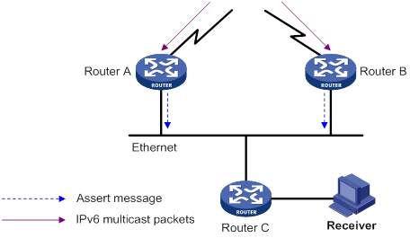
As shown in Figure 92, after Router A and Router B receive an (S, G) packet from the upstream node, they both forward the packet to the local subnet. As a result, the downstream node Router C receives two identical multicast packets. In addition, both Router A and Router B, on their downstream interfaces, receive a duplicate packet forwarded by the other. After detecting this condition, both routers send an assert message to all IPv6 PIM routers on the local subnet through the interface that received the packet. The assert message contains the IPv6 multicast source address (S), the IPv6 multicast group address (G), and the metric preference and metric of the IPv6 unicast route/MBGP route/static multicast route to the IPv6 multicast source. By comparing these parameters, either Router A or Router B becomes the unique forwarder of the subsequent (S, G) packets on the subnet. The comparison process is as follows:
1. The router with a higher metric preference to the IPv6 multicast source wins.
2. If both routers have the same metric preference to the IPv6 multicast source, the router with a smaller metric to the IPv6 multicast source wins.
3. If both routers have the same metric, the router with a higher IPv6 link-local address on the downstream interface wins.
IPv6 PIM-SM overview
IPv6 PIM-DM uses the flood-and-prune cycles to build SPTs for IPv6 multicast data forwarding. Although an SPT has the shortest paths from the IPv6 multicast source to the receivers, it is built with a low efficiency. Therefore, IPv6 PIM-DM is not suitable for large- and medium-sized networks.
IPv6 PIM-SM uses the pull mode for IPv6 multicast forwarding, and it is suitable for large-sized and medium-sized networks with sparsely and widely distributed IPv6 multicast group members.
IPv6 PIM-SM assumes that no hosts need IPv6 multicast data. A multicast receiver must express its interest in the IPv6 multicast data for an IPv6 multicast group before the data is forwarded to it. A rendezvous point (RP) is the core of an IPv6 PIM-SM domain. Relying on the RP, SPTs and rendezvous point trees (RPTs) are established and maintained to implement IPv6 multicast data forwarding. An SPT is rooted at the IPv6 multicast source and has the RPs as its leaves. An RPT is rooted at the RP and has the receiver hosts as its leaves.
Neighbor discovery
IPv6 PIM-SM uses the same neighbor discovery mechanism as IPv6 PIM-DM does. For more information, see "Neighbor discovery."
DR election
A designated router (DR) is required on both the source-side network and receiver-side network. A source-side DR acts on behalf of the IPv6 multicast source to send register messages to the RP. The receiver-side DR acts on behalf of the receiver hosts to send join messages to the RP.
|
|
IMPORTANT: MLD must be enabled on the device that acts as the receiver-side DR. Otherwise, the receiver hosts attached to the DR cannot join any IPv6 multicast groups. For more information about MLD, see "Configuring MLD." |
As shown in Figure 93, the DR election process is as follows:
1. The routers on the shared-media LAN send hello messages to one another. The hello messages contain the DR priority for DR election. The router with the highest DR priority is elected as the DR.
2. The router with the highest IPv6 link-local address wins the DR election under one of the following conditions:
? All the routers have the same DR election priority.
? A router does not support carrying the DR priority in hello messages.
If the DR fails, its IPv6 PIM neighbor lifetime expires, and the other routers initiate a new DR election.
RP discovery
An RP is the core of an IPv6 PIM-SM domain. For a small-sized, simple network, one RP is enough for multicast forwarding throughout the network. In this case, you can specify a static RP on each router in the IPv6 PIM-SM domain. However, in an IPv6 PIM-SM network that covers a wide area, a huge amount of IPv6 multicast data is forwarded by the RP. To lessen the RP burden and optimize the topological structure of the RPT, you can configure multiple candidate-RPs (C-RPs) in an IPv6 PIM-SM domain. An RP is dynamically elected from multiple configured C-RPs by the bootstrap mechanism. An elected RP provides services for a different IPv6 multicast group. For this purpose, you must configure a bootstrap router (BSR). A BSR acts as the administrative core of an IPv6 PIM-SM domain. An IPv6 PIM-SM domain has only one BSR, but can have multiple candidate-BSRs (C-BSRs). If the BSR fails, a new BSR can be automatically elected from the C-BSRs and avoid service interruption.
|
|
NOTE: · An RP can provide services for multiple IPv6 multicast groups, but an IPv6 multicast group only uses one RP. · A device can act as a C-RP and a C-BSR at the same time. |
As shown in Figure 94, each C-RP periodically unicasts its advertisement messages (C-RP-Adv messages) to the BSR. An advertisement message contains the address of the advertising C-RP and the IPv6 multicast group range to which it is designated. The BSR collects these advertisement messages and organizes the C-RP information into an RP-set, which is a database of mappings between IPv6 multicast groups and RPs. The BSR encapsulates the RP-set information in the bootstrap messages (BSMs) and floods the BSMs to the entire IPv6 PIM-SM domain.
Figure 94 Information exchange between C-RPs and BSR
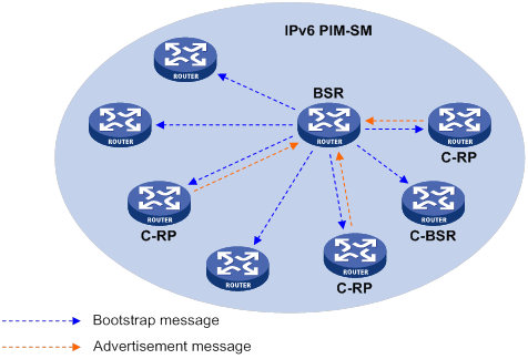
Based on the information in the RP-set, all routers on the network can select an RP for a specific IPv6 multicast group based on the following rules:
1. The C-RP that is designated to the smallest IPv6 multicast group range wins.
2. If the C-RPs are designated to the same IPv6 multicast group range, the C-RP with the highest priority wins.
3. If C-RPs have the same priority, the C-RP with the largest hash value wins. The hash value is calculated through the hash algorithm.
4. If the C-RPs have the same priority and hash value, the C-RP with the highest IPv6 address wins.
Embedded RP
The embedded RP mechanism enables a router to resolve the RP address from an IPv6 multicast group address to map the IPv6 multicast group to an RP. This RP can take the place of the configured static RP or the RP dynamically elected by the bootstrap mechanism. A DR does not need to learn the RP address beforehand. The process is as follows:
· At the receiver side:
a. A receiver host initiates an MLD report to express its interest in an IPv6 multicast group.
b. After receiving the MLD report, the receiver-side DR resolves the RP address embedded in the IPv6 multicast group address and sends a join message to the RP.
· At the IPv6 multicast source side:
c. The IPv6 multicast source sends IPv6 multicast traffic to an IPv6 multicast group.
d. The source-side DR resolves the RP address embedded in the IPv6 multicast address, and sends a register message to the RP.
Anycast RP
IPv6 PIM-SM requires only one active RP to serve each IPv6 multicast group. If the active RP fails, the multicast traffic might be interrupted. The Anycast RP mechanism enables redundancy backup among RPs by configuring multiple RPs with the same IPv6 address for one multicast group. An IPv6 multicast source registers with the closest RP or a receiver-side DR joins the closest RP to implement source information synchronization.
Anycast RP has the following benefits:
· Optimal RP path—An IPv6 multicast source registers with the closest RP to build an optimal SPT. A receiver joins the closest RP to build an optimal RPT.
· Redundancy backup among RPs—When an RP fails, the RP-related sources will register with the closest available RPs and the receiver-side DRs will join the closest available RPs. This provides redundancy backup among RPs.
Anycast RP is implemented by using either of the following methods:
· Anycast RP through MSDP—In this method, you can configure multiple RPs with the same IP address for one multicast group and configure MSDP peering relationships between them. For more information about Anycast RP through MSDP, see "Configuring MSDP."
· Anycast RP through IPv6 PIM-SM—In this method, you can configure multiple RPs for one IPv6 multicast group and add them to an Anycast RP set. This method introduces the following concepts:
? Anycast RP set—A set of RPs that are designated to the same IPv6 multicast group.
? Anycast RP member—Each RP in the Anycast RP set.
? Anycast RP member address—IPv6 address of each Anycast RP member for communication among the RP members.
? Anycast RP address—IPv6 address of the Anycast RP set for communication within the IPv6 PIM-SM domain. It is also known as RPA.
As shown in Figure 95, RP 1, RP 2, and RP 3 are members of an Anycast RP set.
Figure 95 Anycast RP through IPv6 PIM-SM
The following describes how Anycast RP through IPv6 PIM-SM is implemented:
a. RP 1 receives a register message destined to RPA. Because the message is not from other Anycast RP members (RP 2 or RP 3), RP 1 considers that the register message is from the DR. RP 1 changes the source IPv6 address of the register message to its own IPv6 address and sends the message to the other members (RP 2 and RP 3).
If a router acts as both a DR and an RP, it creates a register message, and then forwards the message to the other RP members.
b. After receiving the register message, RP 2 and RP 3 find out that the source address of the register message is an Anycast RP member address. They stop forwarding the message to other routers.
In Anycast RP implementation, an RP must forward the register message from the DR to other Anycast RP members to synchronize IPv6 multicast source information.
RPT building
Figure 96 RPT building in an IPv6 PIM-SM domain

As shown in Figure 96, the process of building an RPT is as follows:
1. When a receiver wants to join the IPv6 multicast group G, it uses an MLD message to inform the receiver-side DR.
2. After getting the receiver information, the DR sends a join message, which travels hop by hop to the RP for the IPv6 multicast group.
3. The routers along the path from the DR to the RP form an RPT branch. Each router on this branch adds to its forwarding table a (*, G) entry, where the asterisk (*) represents any IPv6 multicast source. The RPT is rooted at the RP and has the DR as its leaf.
When the IPv6 multicast data addressed to the IPv6 multicast group G reaches the RP, the RP forwards the data to the DR along the established RPT. Finally, the DR forwards the IPv6 multicast data to the receiver hosts.
When a receiver is no longer interested in the IPv6 multicast data addressed to the IPv6 multicast group G, the receiver-side DR sends a prune message. The prune message goes hop by hop along the RPT to the RP. After receiving the prune message, the upstream node deletes the interface that connects to this downstream node from the outgoing interface list. At the same time, the upstream router checks for the existence of receivers for that IPv6 multicast group. If no receivers for the IPv6 multicast group exist, the router continues to forward the prune message to its upstream router.
IPv6 multicast source registration
The IPv6 multicast source uses the registration process to inform an RP of its presence.
Figure 97 IPv6 multicast source registration

As shown in Figure 97, the IPv6 multicast source registers with the RP as follows:
1. The IPv6 multicast source S sends the first multicast packet to the IPv6 multicast group G. When receiving the multicast packet, the source-side DR that directly connects to the IPv6 multicast source encapsulates the packet into a register message and unicasts the message to the RP.
2. After the RP receives the register message, it decapsulates it and forwards it down to the RPT. Meanwhile, it sends an (S, G) source-specific join message toward the IPv6 multicast source. The routers along the path from the RP to the IPv6 multicast source constitute an SPT branch. Each router on this branch creates an (S, G) entry in its forwarding table.
3. The subsequent IPv6 multicast data from the IPv6 multicast source are forwarded to the RP along the SPT. When the IPv6 multicast data reaches the RP along the SPT, the RP forwards the data to the receivers along the RPT. Meanwhile, it unicasts a register-stop message to the source-side DR to prevent the DR from unnecessarily encapsulating the data.
Switchover to SPT
|
|
CAUTION: If the switch is an RP, disabling switchover to SPT might cause multicast traffic forwarding failures on the source-side DR. When disabling switchover to SPT, be sure you fully understand its impact on your network. |
In an IPv6 PIM-SM domain, only one RP and one RPT provide services for a specific IPv6 multicast group. Before the switchover to SPT occurs, the source-side DR encapsulates all IPv6 multicast data in register messages and sends them to the RP. After receiving these register messages, the RP decapsulates them and forwards them to the receiver-side DR along the RPT.
IPv6 multicast forwarding along the RPT has the following weaknesses:
· Encapsulation and decapsulation are complex on the source-side DR and the RP.
· The path for an IPv6 multicast packet might not be the shortest one.
· The RP might be overloaded by IPv6 multicast traffic bursts.
To eliminate these weaknesses, IPv6 PIM-SM allows an RP or the receiver-side DR to initiate the switchover to SPT when the traffic rate exceeds a specific threshold:
· The RP initiates the switchover to SPT:
The RP periodically checks the multicast packet forwarding rate. If the RP finds that the traffic rate exceeds the specified threshold, it sends an (S, G) source-specific join message toward the IPv6 multicast source. The routers along the path from the RP to the IPv6 multicast source constitute an SPT branch. The subsequent IPv6 multicast data is forwarded to the RP along the SPT without being encapsulated into register messages.
For more information about the switchover to SPT initiated by the RP, see "IPv6 multicast source registration."
· The receiver-side DR initiates the switchover to SPT:
The receiver-side DR periodically checks the forwarding rate of the multicast packets that the IPv6 multicast source S sends to the IPv6 multicast group G. If the forwarding rate exceeds the specified threshold, the DR initiates the switchover to SPT as follows:
a. The receiver-side DR sends an (S, G) source-specific join message toward the IPv6 multicast source. The routers along the path create an (S, G) entry in their forwarding table to constitute an SPT branch.
b. When the multicast packets reach the router where the RPT and the SPT branches, the router drops the multicast packets that travel along the RPT. It then sends a prune message with the RP bit toward the RP.
c. After receiving the prune message, the RP forwards it toward the IPv6 multicast source (supposed only one receiver exists). Thus, the switchover to SPT is completed. The subsequent IPv6 multicast packets for the IPv6 multicast group travel along the SPT from the IPv6 multicast source to the receiver hosts.
With the switchover to SPT, IPv6 PIM-SM builds SPTs more economically than IPv6 PIM-DM does.
Assert
IPv6 PIM-SM uses a similar assert mechanism as IPv6 PIM-DM does. For more information, see "Assert."
IPv6 BIDIR-PIM overview
In some many-to-many applications, such as a multi-side video conference, multiple receivers of an IPv6 multicast group might be interested in the IPv6 multicast data from multiple IPv6 multicast sources. With IPv6 PIM-DM or IPv6 PIM-SM, each router along the SPT must create an (S, G) entry for each IPv6 multicast source, consuming a lot of system resources.
IPv6 BIDIR-PIM addresses the problem. Derived from IPv6 PIM-SM, IPv6 BIDIR-PIM builds and maintains a bidirectional RPT, which is rooted at the RP and connects the IPv6 multicast sources and the receivers. Along the bidirectional RPT, the IPv6 multicast sources send IPv6 multicast data to the RP, and the RP forwards the data to the receivers. Each router along the bidirectional RPT needs to maintain only one (*, G) entry, saving system resources.
IPv6 BIDIR-PIM is suitable for a network with dense IPv6 multicast sources and receivers.
Neighbor discovery
IPv6 BIDIR-PIM uses the same neighbor discovery mechanism as IPv6 PIM-SM does. For more information, see "Neighbor discovery."
RP discovery
IPv6 BIDIR-PIM uses the same RP discovery mechanism as IPv6 PIM-SM does. For more information, see "RP discovery." In IPv6 BIDIR-PIM, an RPF interface is the interface toward an RP, and an RPF neighbor is the address of the next hop to the RP.
In IPv6 PIM-SM, an RP must be specified with a real IPv6 address. In IPv6 BIDIR-PIM, an RP can be specified with a virtual IPv6 address, which is called the "rendezvous point address (RPA)." The link corresponding to the RPA's subnet is called the "rendezvous point link (RPL)." All interfaces connected to the RPL can act as the RPs, and they back up one another.
DF election
On a subnet with multiple multicast routers, duplicate multicast packets might be forwarded to the RP. To address this issue, IPv6 BIDIR-PIM uses a designated forwarder (DF) election mechanism to elect a unique DF on each subnet. Only the DFs can forward IPv6 multicast data to the RP.
DF election is not necessary for an RPL.

As shown in Figure 98, without the DF election mechanism, both Router B and Router C can receive IPv6 multicast packets from Router A. They also can forward the packets to downstream routers on the local subnet. As a result, the RP (Router E) receives duplicate IPv6 multicast packets.
With the DF election mechanism, once receiving the RP information, Router B and Router C multicast a DF election message to all IPv6 PIM routers on the subnet to initiate a DF election process. The election message carries the RP's address, and the route preference and metric of the unicast route to the RP. A DF is elected as follows:
1. The router with higher route preference becomes the DF.
2. If the routers have the same route preference, the router with lower metric becomes the DF.
3. If the routers have the same metric, the router with the higher IP address becomes the DF.
Bidirectional RPT building
A bidirectional RPT comprises a receiver-side RPT and a source-side RPT. The receiver-side RPT is rooted at the RP and takes the routers that directly connect to the receivers as leaves. The source-side RPT is also rooted at the RP but takes the routers that directly connect to the IPv6 multicast sources as leaves. The processes for building these two RPTs are different.
Figure 99 RPT building at the receiver side
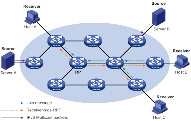
As shown in Figure 99, the process for building a receiver-side RPT is the same as the process for building an RPT in IPv6 PIM-SM:
1. When a receiver wants to join the IPv6 multicast group G, it uses an MLD message to inform the directly connected router.
2. After receiving the message, the router sends a join message, which is forwarded hop by hop to the RP for the IPv6 multicast group.
3. The routers along the path from the receiver's directly connected router to the RP form an RPT branch. Each router on this branch adds a (*, G) entry to its forwarding table.
After a receiver host leaves the IPv6 multicast group G, the directly connected router multicasts a prune message to all IPv6 PIM routers on the subnet. The prune message goes hop by hop along the reverse direction of the RPT to the RP. After receiving the prune message, an upstream node removes the interface that connects to the downstream node from the outgoing interface list. At the same time, the upstream router checks the existence of receivers for that IPv6 multicast group. If no receivers for the IPv6 multicast group exist, the router continues to forward the prune message to its upstream router.
Figure 100 RPT building at the IPv6 multicast source side

As shown in Figure 100, the process for building a source-side RPT is relatively simple:
4. When an IPv6 multicast source sends multicast packets to the IPv6 multicast group G, the DF in each subnet unconditionally forwards the packets to the RP.
5. The routers along the path from the source's directly connected router to the RP constitute an RPT branch. Each router on this branch adds a (*, G) entry to its forwarding table.
After a bidirectional RPT is built, the IPv6 multicast sources send multicast traffic to the RP along the source-side RPT. Then, the RP forwards the traffic to the receivers along the receiver-side RPT.
|
|
IMPORTANT: If a receiver and a source are at the same side of the RP, the source-side RPT and the receiver-side RPT might meet at a node before reaching the RP. In this case, the multicast packets from the IPv6 multicast source to the receiver are directly forwarded by the node, instead of by the RP. |
IPv6 administrative scoping overview
Typically, an IPv6 PIM-SM domain or an IPv6 BIDIR-PIM domain contains only one BSR, which is responsible for advertising RP-set information within the entire domain. Information about all IPv6 multicast groups is forwarded within the network that the BSR administers. This is called the "IPv6 non-scoped BSR mechanism."
IPv6 administrative scoping mechanism
To implement refined management, you can divide an IPv6 PIM-SM domain or IPv6 BIDIR-PIM domain into an IPv6 global-scoped zone and multiple IPv6 administratively-scoped zones (admin-scoped zones). This is called the "IPv6 administrative scoping mechanism."
The administrative scoping mechanism effectively releases stress on the management in a single-BSR domain and enables provision of zone-specific services through private group addresses.
An IPv6 admin-scoped zone is designated to particular IPv6 multicast groups with the same scope field value in their group addresses. Zone border routers (ZBRs) form the boundary of an IPv6 admin-scoped zone. Each IPv6 admin-scoped zone maintains one BSR for IPv6 multicast groups with the same scope field value. IPv6 multicast protocol packets, such as assert messages and BSMs, of these IPv6 multicast groups cannot cross the boundary of the IPv6 admin-scoped zone for the group range. The IPv6 multicast group ranges to which different IPv6 admin-scoped zones are designated can have intersections. However, the IPv6 multicast groups in an IPv6 admin-scoped zone are valid only within its local zone, and theses IPv6 multicast groups are regarded as private group addresses.
The IPv6 global-scoped zone can be regarded as a special IPv6 admin-scoped zone, and it maintains a BSR for the IPv6 multicast groups with the scope field value as 14.
Relationship between IPv6 admin-scoped zones and the IPv6 global-scoped zone
The IPv6 global-scoped zone and each IPv6 admin-scoped zone have their own C-RPs and BSRs. These devices are effective only on their respective zones, and the BSR election and the RP election are implemented independently. Each IPv6 admin-scoped zone has its own boundary. The IPv6 multicast information within a zone cannot cross this boundary in either direction. You can have a better understanding of the IPv6 global-scoped zone and IPv6 admin-scoped zones based on geographical locations and the scope field values.
· In view of geographical locations:
An IPv6 admin-scoped zone is a logical zone for particular IPv6 multicast groups with the same scope field value. The IPv6 multicast packets for such IPv6 multicast groups are confined within the local IPv6 admin-scoped zone and cannot cross the boundary of the zone.
Figure 101 Relationship in view of geographical locations
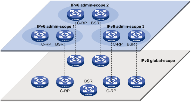
As shown in Figure 101, for the IPv6 multicast groups with the same scope field value, the IPv6 admin-scoped zones must be geographically separated and isolated. The IPv6 global-scoped zone includes all routers in the IPv6 PIM-SM domain or IPv6 BIDIR-PIM domain. IPv6 multicast packets that do not belong to any IPv6 admin-scoped zones are forwarded in the entire IPv6 PIM-SM domain or IPv6 BIDIR-PIM domain.
· In view of the scope field values:
In terms of the scope field values, the scope field in an IPv6 multicast group address shows the zone to which the IPv6 multicast group belongs.
Figure 102 IPv6 multicast address format
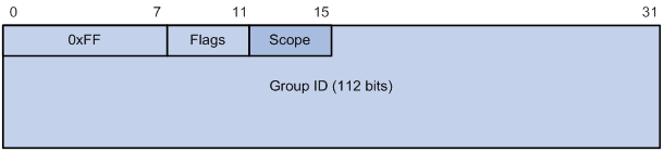
An IPv6 admin-scoped zone with a larger scope field value contains an IPv6 admin-scoped zone with a smaller scope field value. The zone with the scope field value of E is the IPv6 global-scoped zone. Table 24 lists the possible values of the scope field.
Table 24 Values of the Scope field
|
Value |
Meaning |
Remarks |
|
0, F |
Reserved |
N/A |
|
1 |
Interface-local scope |
N/A |
|
2 |
Link-local scope |
N/A |
|
3 |
Subnet-local scope |
IPv6 admin-scoped zone. |
|
4 |
Admin-local scope |
IPv6 admin-scoped zone. |
|
5 |
Site-local scope |
IPv6 admin-scoped zone. |
|
6, 7, 9 through D |
Unassigned |
IPv6 admin-scoped zone. |
|
8 |
Organization-local scope |
IPv6 admin-scoped zone. |
|
E |
Global scope |
IPv6 global-scoped zone. |
IPv6 PIM-SSM overview
The ASM model includes IPv6 PIM-DM and IPv6 PIM-SM. The SSM model can be implemented by leveraging part of the IPv6 PIM-SM technique. It is also called "IPv6 PIM-SSM."
The SSM model provides a solution for source-specific multicast. It maintains the relationship between hosts and routers through MLDv2.
In actual applications, part of MLDv2 and IPv6 PIM-SM techniques are adopted to implement the SSM model. In the SSM model, because receivers have located an IPv6 multicast source, no RP or RPT is required. No source registration process is required for discovering IPv6 multicast sources in other IPv6 PIM domains.
Neighbor discovery
IPv6 PIM-SSM uses the same neighbor discovery mechanism as IPv6 PIM-SM. For more information, see "Neighbor discovery."
DR election
IPv6 PIM-SSM uses the same DR election mechanism as IPv6 PIM-SM. For more information, see "DR election."
SPT building
The decision to build an RPT for IPv6 PIM-SM or an SPT for IPv6 PIM-SSM depends on whether the IPv6 multicast group that the receiver host joins is in the IPv6 SSM group range. The IPv6 SSM group range reserved by IANA is FF3x::/32, where "x" represents any legal address scope.
Figure 103 SPT building in IPv6 PIM-SSM

As shown in Figure 103, Host B and Host C are receivers. They send MLDv2 report messages to their DRs to express their interest in the multicast information that the IPv6 multicast source S sends to the IPv6 multicast group G.
After receiving a report message, the DR first checks whether the group address in the message is in the IPv6 SSM group range and does the following:
· If the group address is in the IPv6 SSM group range, the DR sends a subscribe message hop by hop toward the IPv6 multicast source S. All routers along the path from the DR to the IPv6 multicast source create an (S, G) entry to build an SPT. The SPT is rooted the IPv6 multicast source S and has the receivers as its leaves. This SPT is the transmission channel in IPv6 PIM-SSM.
· If the group address is not in the IPv6 SSM group range, the receiver-side DR sends a (*, G) join message to the RP. The IPv6 multicast source registers with the source-side DR.
In IPv6 PIM-SSM, the term "subscribe message" refers to a join message.
Relationship among IPv6 PIM protocols
In an IPv6 PIM network, IPv6 PIM-DM cannot run together with IPv6 PIM-SM, IPv6 BIDIR-PIM, or IPv6 PIM-SSM. However, IPv6 PIM-SM, IPv6 BIDIR-PIM, and IPv6 PIM-SSM can run together. Figure 104 shows how the device selects one protocol from among them for a receiver trying to join a group.
For more information about MLD SSM mapping, see "Configuring MLD."
Figure 104 Relationship among IPv6 PIM protocols
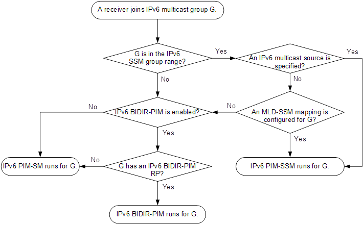
IPv6 PIM support for VPNs
To support IPv6 PIM for VPNs, a multicast router that runs IPv6 PIM maintains an independent set of IPv6 PIM neighbor table, IPv6 multicast routing table, BSR information, and RP-set information for each VPN.
After receiving an IPv6 multicast data packet, the multicast router checks which VPN the IPv6 data packet belongs to. Then, the router forwards the IPv6 packet according to the IPv6 multicast routing table for that VPN or creates an IPv6 multicast routing entry for that VPN.
Protocols and standards
· RFC 3973, Protocol Independent Multicast-Dense Mode (PIM-DM): Protocol Specification(Revised)
· RFC 4601, Protocol Independent Multicast-Sparse Mode (PIM-SM): Protocol Specification (Revised)
· RFC 4610, Anycast-RP Using Protocol Independent Multicast (PIM)
· RFC 3956, Embedding the Rendezvous Point (RP) Address in an IPv6 Multicast Address
· RFC 5015, Bidirectional Protocol Independent Multicast (BIDIR-PIM)
· RFC 5059, Bootstrap Router (BSR) Mechanism for Protocol Independent Multicast (PIM)
· RFC 4607, Source-Specific Multicast for IP
· Draft-ietf-ssm-overview-05, An Overview of Source-Specific Multicast (SSM)
Feature and hardware compatibility
The following matrix shows the feature and hardware compatibility:
|
Hardware |
IPv6 PIM compatibility |
|
MSR810/810-W/810-W-DB/810-LM/810-W-LM/810-10-PoE/810-LM-HK/810-W-LM-HK/810-LMS/810-LUS |
No |
|
MSR2600-6-X1/2600-10-X1 |
Yes |
|
MSR 2630 |
Yes |
|
MSR3600-28/3600-51 |
Yes |
|
MSR3600-28-SI/3600-51-SI |
No |
|
MSR3610-X1/3610-X1-DP/3610-X1-DC/3610-X1-DP-DC |
Yes |
|
MSR 3610/3620/3620-DP/3640/3660 |
Yes |
|
MSR5620/5660/5680 |
Yes |
|
Hardware |
IPv6 PIM compatibility |
|
MSR810-LM-GL |
Yes |
|
MSR810-W-LM-GL |
Yes |
|
MSR830-6EI-GL |
Yes |
|
MSR830-10EI-GL |
Yes |
|
MSR830-6HI-GL |
Yes |
|
MSR830-10HI-GL |
Yes |
|
MSR2600-6-X1-GL |
Yes |
|
MSR3600-28-SI-GL |
No |
Configuring IPv6 PIM-DM
This section describes how to configure IPv6 PIM-DM.
IPv6 PIM-DM configuration task list
|
Tasks at a glance |
|
(Required.) Enabling IPv6 PIM-DM |
|
(Optional.) Enabling the state refresh feature |
|
(Optional.) Configuring state refresh parameters |
|
(Optional.) Configuring IPv6 PIM-DM graft retry timer |
|
(Optional.) Configuring common IPv6 PIM features |
Configuration prerequisites
Before you configure IPv6 PIM-DM, configure an IPv6 unicast routing protocol so that all devices in the domain can interoperate at the network layer.
Enabling IPv6 PIM-DM
Enable IPv6 multicast routing before configuring IPv6 PIM.
With IPv6 PIM-DM enabled on interfaces, routers can establish IPv6 PIM neighbor relationship and process IPv6 PIM messages from their IPv6 PIM neighbors. As a best practice, enable IPv6 PIM-DM on all non-border interfaces of routers when you deploy an IPv6 PIM-DM domain.
|
|
IMPORTANT: All the interfaces on a device must operate in the same IPv6 PIM mode in the public network or the same VPN instance. |
To enable IPv6 PIM-DM:
|
Step |
Command |
Remarks |
|
1. Enter system view. |
system-view |
N/A |
|
2. Enable IPv6 multicast routing and enter IPv6 MRIB view. |
ipv6 multicast routing [ vpn-instance vpn-instance-name ] |
By default, IPv6 multicast routing is disabled. |
|
3. Return to system view. |
quit |
N/A |
|
4. Enter interface view. |
interface interface-type interface-number |
N/A |
|
5. Enable IPv6 PIM-DM. |
ipv6 pim dm |
By default, IPv6 PIM-DM is disabled. |
Enabling the state refresh feature
In an IPv6 PIM-DM domain, this feature enables the IPv6 PIM router that is directly connected to the source to periodically send state refresh messages. It also enables other PIM routers to refresh pruned state timers after receiving the state refresh messages. It prevents the pruned interfaces from resuming multicast forwarding. You must enable this feature on all IPv6 PIM routers on a subnet.
To enable the state refresh feature:
|
Step |
Command |
Remarks |
|
1. Enter system view. |
system-view |
N/A |
|
2. Enter interface view. |
interface interface-type interface-number |
N/A |
|
3. Enable the state refresh feature. |
ipv6 pim state-refresh-capable |
By default, the state refresh feature is enabled. |
Configuring state refresh parameters
The state refresh interval determines the interval at which a router sends state refresh messages. It is configurable.
A router might receive duplicate state refresh messages within a short time. To prevent this situation, you can configure the amount of time that the router must wait to accept a new state refresh message. If the router receives a new state refresh message before the timer expires, it discards the message. If the router receives a new state refresh message after the timer expires, it accepts the message, refreshes its own IPv6 PIM-DM state, and resets the waiting timer.
The hop limit value of a state refresh message decrements by 1 whenever it passes a router before it is forwarded to the downstream node. The state refresh message stops being forwarded when the hop limit comes down to 0. A state refresh message with a large hop limit value might cycle on a small network. To control the propagation scope of state refresh messages, configure an appropriate hop limit value based on the network size on the router directly connected with the IPv6 multicast source.
To configure state refresh parameters:
|
Step |
Command |
Remarks |
|
1. Enter system view. |
system-view |
N/A |
|
2. Enter IPv6 PIM view. |
ipv6 pim [ vpn-instance vpn-instance-name ] |
N/A |
|
3. Configure the state refresh interval. |
state-refresh-interval interval |
The default setting is 60 seconds. |
|
4. Configure the amount of time to wait before accepting a new state refresh message. |
state-refresh-rate-limit time |
The default setting is 30 seconds. |
|
5. Configure the hop limit value of state refresh messages. |
state-refresh-hoplimit hoplimit-value |
The default setting is 255. |
Configuring IPv6 PIM-DM graft retry timer
To configure the IPv6 PIM-DM graft retry timer:
|
Step |
Command |
Remarks |
|
1. Enter system view. |
system-view |
N/A |
|
2. Enter interface view. |
interface interface-type interface-number |
N/A |
|
3. Configure the IPv6 PIM-DM graft retry timer. |
ipv6 pim timer graft-retry interval |
By default, the IPv6 PIM-DM graft retry timer is 3 seconds. |
For more information about the configuration of other timers in IPv6 PIM-DM, see "Configuring common IPv6 PIM timers."
Configuring IPv6 PIM-SM
This section describes how to configure IPv6 PIM-SM.
IPv6 PIM-SM configuration task list
|
Tasks at a glance |
Remarks |
|
(Required.) Enabling IPv6 PIM-SM |
N/A |
|
(Required.) Configuring an RP: · (Optional.) Configuring Anycast RP |
You must configure a static RP, a C-RP, or both in an IPv6 PIM-SM domain. |
|
· (Required.) Configuring a C-BSR · (Optional) Disabling BSM forwarding out of incoming interfaces · (Optional.) Configuring an IPv6 PIM domain border · (Optional.) Disabling BSM semantic fragmentation |
Skip the task of configuring a BSR on a network without C-RPs. |
|
(Optional.) Configuring IPv6 multicast source registration |
N/A |
|
(Optional.) Configuring the switchover to SPT |
N/A |
|
(Optional.) Configuring common IPv6 PIM features |
N/A |
Configuration prerequisites
Before you configure IPv6 PIM-SM, configure an IPv6 unicast routing protocol so that all devices in the domain can interoperate at the network layer.
Enabling IPv6 PIM-SM
Enable IPv6 multicast routing before configuring IPv6 PIM.
With IPv6 PIM-SM enabled on interfaces, routers can establish IPv6 PIM neighbor relationship and process IPv6 PIM messages from their IPv6 PIM neighbors. As a best practice, enable IPv6 PIM-SM on all non-border interfaces on routers when you deploy an IPv6 PIM-SM domain.
|
|
IMPORTANT: All the interfaces on the same router must operate in the same IPv6 PIM mode in the public network or the same VPN instance. |
To enable IPv6 PIM-SM:
|
Step |
Command |
Remarks |
|
1. Enter system view. |
system-view |
N/A |
|
2. Enable IPv6 multicast routing and enter IPv6 MRIB view. |
ipv6 multicast routing [ vpn-instance vpn-instance-name ] |
By default, IPv6 multicast routing is disabled. |
|
3. Return to system view. |
quit |
N/A |
|
4. Enter interface view. |
interface interface-type interface-number |
N/A |
|
5. Enable IPv6 PIM-SM. |
ipv6 pim sm |
By default, IPv6 PIM-SM is disabled. |
Configuring an RP
An RP can provide services for multiple or all IPv6 multicast groups. However, only one RP at a time can forward IPv6 multicast traffic for an IPv6 multicast group.
An RP can be manually configured or dynamically elected through the BSR mechanism. For a large-scaled IPv6 PIM network, configuring static RPs is a tedious job. Generally, static RPs are backups for dynamic RPs to enhance the robustness and operational manageability on an IPv6 multicast network.
Configuring a static RP
If only one dynamic RP exists on a network, you can configure a static RP to avoid communication interruption caused by single-point failures. The static RP can also avoid waste of bandwidth due to frequent message exchange between C-RPs and the BSR.
When you configure static RPs for IPv6 PIM-SM, follow these restrictions and guidelines:
· You can configure the same static RP for different IPv6 multicast groups by using the same RP address but different ACLs.
· You do not need to enable IPv6 PIM for an interface to be configured as a static RP.
· If you configure multiple static RPs for an IPv6 multicast group, only the static RP with the highest IPv6 address takes effect.
· The static RP configuration must be the same on all routers in the IPv6 PIM-SM domain.
To configure a static RP:
|
Step |
Command |
Remarks |
|
1. Enter system view. |
system-view |
N/A |
|
2. Enter IPv6 PIM view. |
ipv6 pim [ vpn-instance vpn-instance-name ] |
N/A |
|
3. Configure a static RP for IPv6 PIM-SM. |
static-rp ipv6-rp-address [ ipv6-acl-number | preferred ] * |
By default, no static RPs exist. |
Configuring a C-RP
In an IPv6 PIM-SM domain, if you want a router to become the RP, you can configure the router as a C-RP. As a best practice, configure C-RPs on backbone routers.
The C-RPs periodically send advertisement messages to the BSR, which collects RP-set information for the RP election. You can configure the interval for sending the advertisement messages.
The holdtime option in C-RP advertisement messages defines the C-RP lifetime for the advertising C-RP. The BSR starts a holdtime timer for a C-RP after it receives an advertisement message. If the BSR does not receive any advertisement message when the timer expires, it considers the C-RP failed or unreachable.
A C-RP policy enables the BSR to filter C-RP advertisement messages by using an ACL that specifies the packet source address range and multicast group addresses. You must configure the same C-RP policy on all C-BSRs in the IPv6 PIM-SM domain because every C-BSR might become the BSR.
When you configure a C-RP, reserve a relatively large bandwidth between the C-RP and the other devices in the IPv6 PIM-SM domain.
The device might use the BSR RP hash algorithm described in RFC 4601 or in RFC 2362 to calculate the RP for a multicast group. To ensure consistent group-to-RP mappings on all PIM routers in the IPv6 PIM-SM domain, specify the same BSR RP hash algorithm on the routers.
To configure a C-RP:
|
Step |
Command |
Remarks |
|
1. Enter system view. |
system-view |
N/A |
|
2. Enter IPv6 PIM view. |
ipv6 pim [ vpn-instance vpn-instance-name ] |
N/A |
|
3. Configure a C-RP. |
c-rp ipv6-address [ advertisement-interval adv-interval | { group-policy ipv6-acl-number | scope scope-id } | holdtime hold-time | priority priority ] * |
By default, no C-RPs exist. |
|
4. (Optional.) Configure a C-RP policy. |
crp-policy ipv6-acl-number |
By default, no C-RP policies exist, and all C-RP advertisement messages are regarded as legal. |
|
5. (Optional.) Configure the device to use the BSR RP hash algorithm described in RFC 2362. |
bsr-rp-mapping rfc2362 |
By default, the device uses the BSR RP hash algorithm described in RFC 4601. |
Configuring Anycast RP
|
|
IMPORTANT: The Anycast RP address must be different from the BSR address. Otherwise, the other Anycast member devices will discard the BSM sent by the BSR. |
You must configure the static RP or C-RPs in the IPv6 PIM-SM domain before you configure the Anycast RP. Use the address of the static RP or the dynamically elected RP as the Anycast RP address.
When you configure Anycast RP, follow these restrictions and guidelines:
· You must add the device that the Anycast RP resides as an RP member to the Anycast RP set. The RP member address cannot be the same as the Anycast RP address.
· You must add all RP member addresses (including the local RP member address) to the Anycast RP set on each member RP device.
· As a best practice, configure no more than 16 Anycast RP members for an Anycast RP set.
· As a best practice, specify the loopback interface address of an RP member device as the RP member address. If you add multiple interface addresses of an RP member device to an Anycast RP set, the lowest IPv6 address becomes the Anycast RP member address. The rest of the interface addresses become backup RP member addresses.
To configure Anycast RP:
|
Step |
Command |
Remarks |
|
1. Enter system view. |
system-view |
N/A |
|
2. Enter IPv6 PIM view. |
N/A |
|
|
By default, Anycast RP is not configured. You can repeat this command to add multiple RP member addresses to an Anycast RP set. |
Configuring a BSR
You must configure a BSR if C-RPs are configured to dynamically select the RP. You do not need to configure a BSR when you have configured only a static RP but no C-RPs.
An IPv6 PIM-SM domain can have only one BSR, but must have a minimum of one C-BSR. Any router can be configured as a C-BSR. Elected from C-BSRs, the BSR is responsible for collecting and advertising RP information in the IPv6 PIM-SM domain.
The BSR election process is summarized as follows:
1. Initially, each C-BSR regards itself as the BSR of the IPv6 PIM-SM domain and sends a BSM to other routers in the domain.
2. When a C-BSR receives the BSM from another C-BSR, it compares its own priority with the priority carried in the message. The C-BSR with a higher priority wins the BSR election. If a tie exists in the priority, the C-BSR with a higher IPv6 address wins. The loser uses the winner's BSR address to replace its own BSR address and no longer regards itself as the BSR. The winner retains its own BSR address and continues to regard itself as the BSR.
The elected BSR distributes the RP-set information collected from C-RPs to all routers in the IPv6 PIM-SM domain. All routers use the same hash algorithm to get an RP for a specific IPv6 multicast group.
Configuring a C-BSR
A BSR policy enables the router to filter BSR messages by using an ACL that specifies the legal BSR addresses. Configure a BSR policy to guard against the following BSR spoofing cases:
· Some maliciously configured hosts can forge BSMs to fool routers and change RP mappings. Such attacks often occur on border routers
· When an attacker controls a router on the network, the attacker can configure the router as a C-BSR to win the BSR election. Through this router, the attacker controls the advertising of RP information.
When you configure a C-BSR, follow these restrictions and guidelines:
· Configure C-BSRs on routers that are on the backbone network.
· Reserve a relatively large bandwidth between the C-BSR and the other devices in the IPv6 PIM-SM domain.
· You must configure the same BSR policy on all routers in the IPv6 PIM-SM domain. The BSR policy discards illegal BSR messages, but it partially guards against BSR attacks on the network. If an attacker controls a legal BSR, the problem still exists.
To configure a C-BSR:
|
Step |
Command |
Remarks |
|
1. Enter system view. |
system-view |
N/A |
|
2. Enter IPv6 PIM view. |
ipv6 pim [ vpn-instance vpn-instance-name ] |
N/A |
|
3. Configure a C-BSR. |
c-bsr ipv6-address [ scope scope-id ] [ hash-length hash-length | priority priority ] * |
By default, no C-BSRs exist. |
|
4. (Optional.) Configure a BSR policy. |
bsr-policy ipv6-acl-number |
By default, no BSR policies exist, and all bootstrap messages are regarded as legal. |
Configuring an IPv6 PIM domain border
An IPv6 PIM domain border determines the transmission boundary of bootstrap messages. Bootstrap messages cannot cross the domain border in either direction. A number of IPv6 PIM domain border interfaces partition a network into different IPv6 PIM-SM domains.
To configure an IPv6 PIM border domain:
|
Step |
Command |
Remarks |
|
1. Enter system view. |
system-view |
N/A |
|
2. Enter interface view. |
interface interface-type interface-number |
N/A |
|
3. Configuring an IPv6 PIM domain border. |
ipv6 pim bsr-boundary |
By default, an interface is not an IPv6 PIM domain border. |
Disabling BSM semantic fragmentation
BSM semantic fragmentation enables a BSR to split a BSM into multiple BSM fragments (BSMFs) if the BSM exceeds the MTU. In this way, a non-BSR router can update the RP-set information for a group range after receiving all BSMFs for the group range. The loss of one BSMF only affects the RP-set information of the group ranges that the fragment contains.
If the IPv6 PIM-SM domain contains a device that does not support this feature, you must disable BSM semantic fragmentation on all C-BSRs. If you do not disable this feature, such a device regards a BSMF as a BSM and updates the RP-set information each time it receives a BSMF. It learns only part of the RP-set information, which further affects the RP election.
To disable BSM semantic fragmentation:
|
Step |
Command |
Remarks |
|
1. Enter system view. |
system-view |
N/A |
|
2. Enter IPv6 PIM view. |
ipv6 pim [ vpn-instance vpn-instance-name ] |
N/A |
|
3. Disable BSM semantic fragmentation. |
undo bsm-fragment enable |
By default, BSM semantic fragmentation is enabled. |
|
|
NOTE: Generally, a BSR performs BSM semantic fragmentation according to the MTU of its BSR interface. For BSMs originated due to learning of a new IPv6 PIM neighbor, semantic fragmentation is performed according to the MTU of the interface that sends the BSMs. |
Disabling BSM forwarding out of incoming interfaces
By default, the device is enabled to forward BSMs out of incoming interfaces. This feature avoids devices in the IPv6 PIM-SM domain might from failing to receive BSMs due to inconsistent routing information. To reduce traffic, you can disable this feature if all the devices have consistent routing information.
To disable the device from sending BSMs out of incoming interfaces:
|
Step |
Command |
Remarks |
|
1. Enter system view. |
system-view |
N/A |
|
2. Enter IPv6 PIM view. |
ipv6 pim [ vpn-instance vpn-instance-name ] |
N/A |
|
3. Disable the device to send BSMs out of incoming interfaces. |
undo bsm-reflection enable |
By default, the device sends BSMs out of incoming interfaces. |
Configuring IPv6 multicast source registration
An IPv6 PIM register policy enables an RP to filter register messages by using an ACL that specifies the IPv6 multicast sources and groups. The policy limits the multicast groups to which the RP is designated. If a register message is denied by the ACL or does not match the ACL, the RP discards the register message and sends a register-stop message to the source-side DR. The registration process stops.
You can configure the device to calculate the checksum based on the entire register message to ensure the information integrity of a register message in the transmission process. If a device that does not support this feature is present on the network, you can configure the device to calculate the checksum based on the register message header.
The RP sends a register-stop message to the source-side DR in one of the following conditions:
· The RP stops providing services to the receivers for an IPv6 multicast group. The receivers do not receive IPv6 multicast data addressed to the IPv6 multicast group through the RP.
· The RP receives IPv6 multicast data that travels along the SPT.
After receiving the register-stop message, the DR stops sending register messages encapsulated with IPv6 multicast data and starts a register-stop timer. Before the register-stop timer expires, the DR sends a null register message (a register message without encapsulated IPv6 multicast data) to the RP and starts a register probe timer. If the DR receives a register-stop message before the register probe timer expires, it resets its register-stop timer. Otherwise, the DR starts sending register messages with encapsulated data again.
The register-stop timer is set to a random value chosen uniformly from (0.5 × register_suppression_time minus register_probe_time) to (1.5 × register_suppression_time minus register_probe_time). The register_probe_time is (5 seconds).
On all C-RP routers, perform the following tasks:
· Configure an IPv6 PIM register policy.
· Configure the routers to calculate the checksum based on the entire register messages or the register message header.
On all routers that might become the source-side DR, configure the register suppression time.
To configure IPv6 multicast source registration:
|
Step |
Command |
Remarks |
|
1. Enter system view. |
system-view |
N/A |
|
2. Enter IPv6 PIM view. |
ipv6 pim [ vpn-instance vpn-instance-name ] |
N/A |
|
3. Configure an IPv6 PIM register policy. |
register-policy ipv6-acl-number |
By default, no IPv6 register policies exist, and all IPv6 register messages are regarded as legal. |
|
4. Configure the device to calculate the checksum based on the entire register message. |
register-whole-checksum |
By default, the device calculates the checksum based on the header of a register message. |
|
5. Configure the register suppression time. |
The default setting is 60 seconds. |
Configuring the switchover to SPT
|
|
CAUTION: If the router is an RP, disabling the switchover to SPT might cause multicast traffic forwarding failures on the source-side DR. When disabling switchover to SPT, make sure you fully understand its impact on your network. |
Both the receiver-side DR and RP can monitor the traffic rate of passing-by IPv6 multicast packets and thus trigger the switchover from RPT to SPT. The monitor function is not available on switches.
To configure the switchover to SPT:
|
Step |
Command |
Remarks |
|
1. Enter system view. |
system-view |
N/A |
|
2. Enter IPv6 PIM view. |
ipv6 pim [ vpn-instance vpn-instance-name ] |
N/A |
|
3. Configure the switchover to SPT. |
spt-switch-threshold { traffic-rate | immediacy | infinity } [ group-policy ipv6-acl-number ] |
By default, the first IPv6 multicast data packet triggers the RPT to SPT switchover. The traffic-rate argument is not supported on switches. |
Configuring IPv6 BIDIR-PIM
This section describes how to configure IPv6 BIDIR-PIM.
IPv6 BIDIR-PIM configuration task list
|
Tasks at a glance |
Remarks |
|
(Required.) Enabling IPv6 BIDIR-PIM |
N/A |
|
(Required.) Configuring an RP: |
You must configure a static RP, a C-RP, or both in an IPv6 BIDIR-PIM domain. |
|
· (Required.) Configuring a C-BSR · (Optional.) Configuring an IPv6 PIM domain border · (Optional.) Disabling BSM semantic fragmentation · (Optional.) Disabling BSM forwarding out of incoming interfaces |
Skip the task of configuring a BSR on an IPv6 network without C-RPs. |
|
(Optional.) Configuring common IPv6 PIM features |
N/A |
|
(Optional.) Enabling SNMP notifications for IPv6 PIM |
N/A |
|
(Optional.) Configuring common IPv6 PIM features |
N/A |
Configuration prerequisites
Before you configure IPv6 BIDIR-PIM, configure an IPv6 unicast routing protocol so that all devices in the domain can interoperate at the network layer.
Enabling IPv6 BIDIR-PIM
Because IPv6 BIDIR-PIM is implemented on the basis of IPv6 PIM-SM, you must enable IPv6 PIM-SM before enabling IPv6 BIDIR-PIM. As a best practice, enable IPv6 PIM-SM on all non-border interfaces on routers when you deploy an IPv6 BIDIR-PIM domain.
|
|
IMPORTANT: All interfaces on a device must be enabled with the same IPv6 PIM mode. |
To enable IPv6 BIDIR-PIM:
|
Step |
Command |
Remarks |
|
1. Enter system view. |
system-view |
N/A |
|
2. Enable IPv6 multicast routing and enter MRIB view. |
ipv6 multicast routing [ vpn-instance vpn-instance-name ] |
By default, IPv6 multicast routing is disabled. |
|
3. Return to system view. |
quit |
N/A |
|
4. Enter interface view. |
interface interface-type interface-number |
N/A |
|
5. Enable IPv6 PIM-SM. |
ipv6 pim sm |
By default, IPv6 PIM-SM is disabled. |
|
6. Return to system view. |
quit |
N/A |
|
7. Enter IPv6 PIM view |
ipv6 pim [ vpn-instance vpn-instance-name ] |
N/A |
|
8. Enable IPv6 BIDIR-PIM |
bidir-pim enable |
By default, IPv6 BIDIR-SM is disabled. |
Configuring an RP
|
|
CAUTION: When both IPv6 PIM-SM and IPv6 BIDIR-PIM run on the IPv6 PIM network, do not use the same RP to provide services for IPv6 PIM-SM and IPv6 BIDIR-PIM. Otherwise, exceptions might occur to the IPv6 PIM routing table. |
An RP can provide services for multiple or all IPv6 multicast groups. However, only one RP at a time can forward IPv6 multicast traffic for an IPv6 multicast group.
An RP can be manually configured or dynamically elected through the BSR mechanism. For a large-scaled IPv6 PIM network, configuring static RPs is a tedious job. Generally, static RPs are backups for dynamic RPs to enhance the robustness and operational manageability on an IPv6 multicast network.
Configuring a static RP
If only one dynamic RP exists on a network, you can configure a static RP to avoid communication interruption caused by single-point failures. The static RP can also avoid bandwidth waste due to frequent message exchange between C-RPs and the BSR.
In IPv6 BIDIR-PIM, a static RP can be specified with an unassigned IPv6 address. This address must be on the same subnet with the link on which the static RP is configured. For example, if the IPv6 addresses of the interfaces at the two ends of a link are 1001::1/64 and 1001::2/64, you can assign 1001::100/64 to the static RP. As a result, the link becomes an RPL.
When you configure static RPs for IPv6 BIDIR-PIM, follow these restrictions and guidelines:
· You can configure the same static RP for different IPv6 multicast groups by using the same RP address but different ACLs.
· You do not need to enable IPv6 PIM for an interface to be configured as a static RP.
· If you configure multiple static RPs for an IPv6 multicast group, only the static RP with the highest IPv6 address takes effect.
· The static RP configuration must be the same on all routers in the IPv6 BIDIR-PIM domain.
To configure a static RP for IPv6 BIDIR-PIM:
|
Step |
Command |
Remarks |
|
1. Enter system view. |
system-view |
N/A |
|
2. Enter IPv6 PIM view. |
ipv6 pim [ vpn-instance vpn-instance-name ] |
N/A |
|
3. Configure a static RP for IPv6 BIDIR-PIM. |
static-rp ipv6-rp-address bidir [ ipv6-acl-number | preferred ] * |
By default, no static RPs exist. |
Configuring a C-RP
|
|
IMPORTANT: · When you configure a C-RP, reserve a large bandwidth between the C-RP and other devices in the IPv6 BIDIR-PIM domain. · As a best practice, configure C-RPs on backbone routers. |
In an IPv6 BIDIR-PIM domain, if you want a router to become the RP, you can configure the router as a C-RP. The BSR collects the C-RP information according to the received advertisement messages from C-RPs or the auto-RP announcements from other routers. Then, it organizes the C-RP information into the RP-set information, which is flooded throughout the entire network. The other routers in the network can determine the RPs for different IPv6 multicast group ranges based on the RP-set information.
To enable the BSR to distribute the RP-set information in the BIDIR-PIM domain, the C-RPs must periodically send advertisement messages to the BSR. The BSR learns the C-RP information, encapsulates the C-RP information and its own IPv6 address in a BSM, and floods the BSM to all IPv6 PIM routers in the domain.
An advertisement message contains a holdtime option, which defines the C-RP lifetime for the advertising C-RP. After the BSR receives an advertisement message from a C-RP, it starts a timer for the C-RP. If the BSR does not receive any advertisement message when the timer expires, it considers the C-RP failed or unreachable.
The device might use the BSR RP hash algorithm described in RFC 4601 or in RFC 2362 to calculate the RP for a multicast group. To ensure consistent group-to-RP mappings on all PIM routers in the IPv6 BIDIR-PIM domain, specify the same BSR RP hash algorithm on the routers.
To configure a C-RP:
|
Step |
Command |
Remarks |
|
1. Enter system view. |
system-view |
N/A |
|
2. Enter IPv6 PIM view. |
ipv6 pim [ vpn-instance vpn-instance-name ] |
N/A |
|
3. Configure a C-RP to provide services for IPv6 BIDIR-PIM. |
c-rp ipv6-address [ advertisement-interval adv-interval | { group-policy ipv6-acl-number | scope scope-id } | holdtime hold-time | priority priority ] * bidir |
By default, no C-RPs exist. |
|
4. (Optional.) Configure the device to use RP hash algorithm described in RFC 2362. |
bsr-rp-mapping rfc2362 |
By default, the device uses the BSR RP hash algorithm described in RFC 4601. |
Configuring the maximum number of IPv6 BIDIR-PIM RPs
In an IPv6 BIDIR-PIM domain, one DF election per RP is implemented on all IPv6 PIM-enabled interfaces. As a best practice, do not configure multiple IPv6 BIDIR-PIM to avoid unnecessary DF elections.
This configuration sets a limit on the number of IPv6 BIDIR-PIM RPs. If the number of RPs exceeds the limit, excess RPs do not take effect and can be used only for DF election rather than IPv6 multicast data forwarding. The system does not delete these excess RPs. They must be deleted manually.
To configure the maximum number of RPs:
|
Step |
Command |
Remarks |
|
1. Enter system view. |
system-view |
N/A |
|
2. Enter IPv6 PIM view. |
ipv6 pim [ vpn-instance vpn-instance-name ] |
N/A |
|
3. Configure the maximum number of RPs. |
bidir-rp-limit limit |
The default upper limit depends on the device model. |
Configuring a BSR
You must configure a BSR if C-RPs are configured to dynamically select the RP. You do not need to configure a BSR when you have configured only a static RP but no C-RPs.
An IPv6 BIDIR-PIM domain can have only one BSR, but must have a minimum of one C-BSR. Any router can be configured as a C-BSR. Elected from C-BSRs, the BSR is responsible for collecting and advertising RP information in the IPv6 BIDIR-PIM domain.
The BSR election process is summarized as follows:
1. Initially, each C-BSR regards itself as the BSR of the IPv6 BIDIR-PIM domain and sends BSMs to other routers in the domain.
2. When a C-BSR receives the BSM from another C-BSR, it compares its own priority with the priority carried in the message. The C-BSR with a higher priority wins the BSR election. If a tie exists in the priority, the C-BSR with a higher IPv6 address wins. The loser uses the winner's BSR address to replace its own BSR address and no longer regards itself as the BSR. The winner retains its own BSR address and continues to regard itself as the BSR.
The elected BSR distributes the RP-set information collected from C-RPs to all routers in the IPv6 BIDIR-PIM domain. All routers use the same hash algorithm to get an RP for a specific IPv6 multicast group.
Configuring a C-BSR
|
|
IMPORTANT: Because the BSR and other devices exchange a large amount of information in the IPv6 BIDIR-PIM domain, reserve a large bandwidth between the C-BSR and other devices. |
A BSR policy enables the router to filter BSR messages by using an ACL that specifies the legal BSR addresses. Configure a BSR policy to guard against the following BSR spoofing cases:
· Some maliciously configured hosts can forge BSMs to fool routers and change RP mappings. Such attacks often occur on border routers.
· When an attacker controls a router on the network, the attacker can configure the router as a C-BSR to win the BSR election. Through this router, the attacker controls the advertising of RP information.
When you configure a C-BSR, follow these restrictions and guidelines:
· C-BSRs should be configured on routers on the backbone network.
· You must configure the same BSR policy on all routers in the IPv6 BIDIR-PIM domain. The BSR policy discards illegal BSR messages, but it partially guards against BSR attacks on the network. If an attacker controls a legal BSR, the problem still exists.
To configure a C-BSR:
|
Step |
Command |
Remarks |
|
1. Enter system view. |
system-view |
N/A |
|
2. Enter IPv6 PIM view. |
ipv6 pim [ vpn-instance vpn-instance-name ] |
N/A |
|
3. Configure a C-BSR. |
c-bsr ipv6-address [ scope scope-id ] [ hash-length hash-length | priority priority ] * |
By default, no C-BSRs exist. |
|
4. (Optional.) Configure a BSR policy. |
bsr-policy ipv6-acl-number |
By default, no BSR policies exist, and all bootstrap messages are regarded as legal. |
Configuring an IPv6 PIM domain border
An IPv6 PIM domain border determines the transmission boundary of bootstrap messages. Bootstrap messages cannot cross the domain border in either direction. A number of PIM domain border interfaces partition a network into different IPv6 BIDIR-PIM domains.
To configure an IPv6 PIM domain border:
|
Step |
Command |
Remarks |
|
1. Enter system view. |
system-view |
N/A |
|
2. Enter interface view. |
interface interface-type interface-number |
N/A |
|
3. Configure an IPv6 PIM domain border. |
ipv6 pim bsr-boundary |
By default, an interface is not an IPv6 PIM domain border. |
Disabling BSM semantic fragmentation
BSM semantic fragmentation enables a BSR to split a BSM into multiple BSM fragments (BSMFs) if the BSM exceeds the MTU. In this way, a non-BSR router can update the RP-set information for a group range after receiving all BSMFs for the group range. The loss of one BSMF only affects the RP-set information of the group ranges that the fragment contains.
If the IPv6 BIDIR-PIM domain contains a device that does not support this feature, you must disable BSM semantic fragmentation on all C-BSRs. If you do not disable this feature, such a device regards a BSMF as an entire BSM and updates the RP-set information each time it receives a BSMF. It learns only part of the RP-set information, which further affects the RP election.
To disable BSM semantic fragmentation:
|
Step |
Command |
Remarks |
|
1. Enter system view. |
system-view |
N/A |
|
2. Enter IPv6 PIM view. |
ipv6 pim [ vpn-instance vpn-instance-name ] |
N/A |
|
3. Disable BSM semantic fragmentation. |
undo bsm-fragment enable |
By default, BSM semantic fragmentation is enabled. |
|
|
NOTE: Generally, a BSR performs BSM semantic fragmentation according to the MTU of its BSR interface. For BSMs originated due to learning of a new IPv6 PIM neighbor, semantic fragmentation is performed according to the MTU of the interface that sends the BSMs. |
Disabling BSM forwarding out of incoming interfaces
By default, the device is enabled to forward BSMs out of incoming interfaces. This feature avoids devices in the IPv6 PIM-SM domain might from failing to receive BSMs due to inconsistent routing information. to reduce traffic, you can disable this feature if all the devices have consistent routing information.
To disable the device from sending BSMs out of incoming interfaces:
|
Step |
Command |
Remarks |
|
1. Enter system view. |
system-view |
N/A |
|
2. Enter IPv6 PIM view. |
ipv6 pim [ vpn-instance vpn-instance-name ] |
N/A |
|
3. Disable the device from sending BSMs out of incoming interfaces. |
undo bsm-reflection enable |
By default, the device sends BSMs out of incoming interfaces. |
Configuring IPv6 PIM-SSM
IPv6 PIM-SSM requires MLDv2 support. Enable MLDv2 on IPv6 PIM routers that connect to multicast receivers.
IPv6 PIM-SSM configuration task list
|
Tasks at a glance |
|
(Required.) Enabling IPv6 PIM-SM |
|
(Optional.) Configuring the IPv6 SSM group range |
|
(Optional.) Configuring common IPv6 PIM features |
Configuration prerequisites
Before you configure IPv6 PIM-SSM, configure an IPv6 unicast IPv6 routing protocol so that all devices in the domain can interoperate at the network layer.
Enabling IPv6 PIM-SM
Before you configure IPv6 PIM-SSM, you must enable IPv6 PIM-SM, because the implementation of the IPv6 SSM model is based on subsets of IPv6 PIM-SM.
When you deploy an IPv6 PIM-SSM domain, enable IPv6 PIM-SM on non-border interfaces of the routers.
|
|
IMPORTANT: All the interfaces on a device must be enabled with the same IPv6 PIM mode. |
To enable IPv6 PIM-SM:
|
Step |
Command |
Remarks |
|
1. Enter system view. |
system-view |
N/A |
|
2. Enable IP multicast routing, and enter MRIB view. |
ipv6 multicast routing [ vpn-instance vpn-instance-name ] |
By default, IPv6 multicast routing is disabled. |
|
3. Return to system view. |
quit |
N/A |
|
4. Enter interface view. |
interface interface-type interface-number |
N/A |
|
5. Enable IPv6 PIM-SM. |
ipv6 pim sm |
By default, IPv6 PIM-SM is disabled. |
Configuring the IPv6 SSM group range
When an IPv6 PIM-SM enabled interface receives an IPv6 multicast packet, it checks whether the IPv6 multicast group address of the packet is in the IPv6 SSM group range. If the IPv6 multicast group address is in this range, the IPv6 PIM mode for this packet is IPv6 PIM-SSM. If the IPv6 multicast group address is not in this range, the IPv6 PIM mode is IPv6 PIM-SM.
Configuration restrictions and guidelines
When you configure the IPv6 SSM group range, follow these restrictions and guidelines:
· Configure the same IPv6 SSM group range on all routers in the entire IPv6 PIM-SM domain. Otherwise, IPv6 multicast information cannot be delivered through the IPv6 SSM model.
· When a member of an IPv6 multicast group in the IPv6 SSM group range sends an MLDv1 report message, the device does not trigger a (*, G) join.
Configuration procedure
To configure an IPv6 SSM group range:
|
Step |
Command |
Remarks |
|
1. Enter system view. |
system-view |
N/A |
|
2. Enter IPv6 PIM view. |
ipv6 pim |
N/A |
|
3. Configure the IPv6 SSM group range. |
ssm-policy ipv6-acl-number |
The default range is FF3x::/32, where x can be any valid scope. |
Configuring common IPv6 PIM features
Configuration task list
|
Tasks at a glance |
|
(Optional.) Configuring an IPv6 multicast source policy |
|
(Optional.) Configuring an IPv6 PIM hello policy |
|
(Optional.) Configuring IPv6 PIM hello message options |
|
(Optional.) Configuring common IPv6 PIM timers |
|
(Optional.) Setting the maximum size of each join or prune message |
|
(Optional.) Enabling BFD for IPv6 PIM |
|
(Optional.) Enabling IPv6 PIM passive mode |
|
(Optional.) Enabling IPv6 PIM NSR |
|
(Optional.) Enabling SNMP notifications for IPv6 PIM |
|
(Optional.) Enabling NBMA mode for IPv6 ADVPN tunnel interfaces |
Configuration prerequisites
Before you configure common IPv6 PIM features, complete the following tasks:
· Configure an IPv6 unicast routing protocol so that all devices in the domain can interoperate at the network layer.
· Configure IPv6 PIM-DM or IPv6 PIM-SSM.
Configuring an IPv6 multicast source policy
This feature enables the device to filter IPv6 multicast data by using an ACL that specifies the IPv6 multicast sources and the optional groups. It filters not only IPv6 multicast data packets but also IPv6 PIM register messages with IPv6 multicast data encapsulated. This also reduces the IPv6 multicast traffic on the network.
To configure an IPv6 multicast source policy:
|
Step |
Command |
Remarks |
|
1. Enter system view. |
system-view |
N/A |
|
2. Enter IPv6 PIM view. |
ipv6 pim [ vpn-instance vpn-instance-name ] |
N/A |
|
3. Configure an IPv6 multicast source policy. |
source-policy ipv6-acl-number |
By default, no IPv6 multicast source policies exist, and all IPv6 multicast data packets are forwarded. |
Configuring an IPv6 PIM hello policy
This feature enables the device to filter IPv6 PIM hello messages by using an ACL that specifies the packet source addresses. It is used to guard against IPv6 PIM message attacks and to establish correct IPv6 PIM neighboring relationships.
If hello messages of an existing IPv6 PIM neighbor are filtered out by the policy, the neighbor is automatically removed when its aging timer expires.
To configure an IPv6 PIM hello policy:
|
Step |
Command |
Remarks |
|
1. Enter system view. |
system-view |
N/A |
|
2. Enter interface view. |
interface interface-type interface-number |
N/A |
|
3. Configure an IPv6 PIM hello policy. |
ipv6 pim neighbor-policy ipv6-acl-number |
By default, no IPv6 PIM hello policies exist on an interface, and all IPv6 PIM hello messages are regarded as legal. |
Configuring IPv6 PIM hello message options
In either an IPv6 PIM-DM domain or an IPv6 PIM-SM domain, hello messages exchanged among routers contain the following configurable options:
· DR_Priority (for IPv6 PIM-SM only)—Priority for DR election. The device with the highest priority wins the DR election. You can configure this option for all the routers in a shared-media LAN that directly connects to the IPv6 multicast source or the receivers.
· Holdtime—IPv6 PIM neighbor lifetime. If a router receives no hello message from a neighbor when the neighbor lifetime expires, it regards the neighbor failed or unreachable.
· LAN_Prune_Delay—Delay of pruning a downstream interface on a shared-media LAN. This option has LAN delay, override interval, and neighbor tracking support (the capability to disable join message suppression).
The LAN delay defines the IPv6 PIM message propagation delay. The override interval defines a time period for a downstream router to override a prune message. If the propagation delay or override interval on different IPv6 PIM routers on a shared-media LAN are different, the largest ones apply.
On the shared-media LAN, the propagation delay and override interval are used as follows:
? If a router receives a prune message on its upstream interface, it means that there are downstream routers on the shared-media LAN. If this router still needs to receive multicast data, it must send a join message to override the prune message within the override interval.
? When a router receives a prune message from its downstream interface, it does not immediately prune this interface. Instead, it starts a timer (the propagation delay plus the override interval). If interface receives a join message before the timer expires, the router does not prune the interface. Otherwise, the router prunes the interface.
If you enable neighbor tracking on an upstream router, this router can track the states of the downstream nodes for which the joined state holdtime timer has not expired. If you want to enable neighbor tracking, you must enable it on all IPv6 PIM routers on a shared-media LAN. Otherwise, the upstream router cannot track join messages from every downstream routers.
· Generation ID—A router generates a generation ID for hello messages when an interface is enabled with IPv6 PIM. The generation ID is a random value, but only changes when the status of the router changes. If an IPv6 PIM router finds that the generation ID in a hello message from the upstream router has changed, it considers that the status of the upstream router has changed. In this case, it sends a join message to the upstream router for status update. You can configure an interface to drop hello messages without the generation ID options to promptly know the status of an upstream router.
You can configure hello message options for all interfaces in IPv6 PIM view or for the current interface in interface view. The configuration made in interface view takes priority over the configurations made in IPv6 PIM view.
Configuring hello message options globally
|
Step |
Command |
Remarks |
|
1. Enter system view. |
system-view |
N/A |
|
2. Enter IPv6 PIM view. |
ipv6 pim [ vpn-instance vpn-instance-name ] |
N/A |
|
3. Set the DR priority. |
hello-option dr-priority priority |
The default setting is 1. |
|
4. Set the neighbor lifetime. |
hello-option holdtime time |
The default setting is 105 seconds. |
|
5. Set the IPv6 PIM message propagation delay for a shared-media LAN. |
hello-option lan-delay delay |
The default setting is 500 milliseconds. |
|
6. Set the override interval. |
hello-option override-interval interval |
The default setting is 2500 milliseconds. |
|
7. Enable neighbor tracking. |
hello-option neighbor-tracking |
By default, neighbor tracking is disabled. |
Configuring hello message options on an interface
|
Step |
Command |
Remarks |
|
1. Enter system view. |
system-view |
N/A |
|
2. Enter interface view. |
interface interface-type interface-number |
N/A |
|
3. Set the DR priority. |
ipv6 pim hello-option dr-priority priority |
The default setting is 1. |
|
4. Set the neighbor lifetime. |
ipv6 pim hello-option holdtime time |
The default setting is 105 seconds. |
|
5. Set the IPv6 PIM message propagation delay. |
ipv6 pim hello-option lan-delay delay |
The default setting is 500 milliseconds. |
|
6. Set the override interval. |
ipv6 pim hello-option override-interval interval |
The default setting is 2500 milliseconds. |
|
7. Enable neighbor tracking. |
ipv6 pim hello-option neighbor-tracking |
By default, neighbor tracking is disabled. |
|
8. Enable dropping hello messages without the Generation ID option. |
ipv6 pim require-genid |
By default, an interface accepts hello messages without the Generation ID option. |
Configuring common IPv6 PIM timers
|
|
IMPORTANT: To prevent the upstream neighbors from aging out, you must configure the interval for sending join/prune messages to be less than the joined/pruned state holdtime timer. |
The following are common timers in IPv6 PIM:
· Hello interval—Interval at which an IPv6 PIM router sends hello messages to discover IPv6 PIM neighbors and maintain IPv6 PIM neighbor relationship.
· Triggered hello delay—Maximum delay for sending a hello message to avoid collisions caused by simultaneous hello messages. After receiving a hello message, an IPv6 PIM router waits for a random time before sending a hello message. This random time is in the range of 0 to the triggered hello delay.
· Join/Prune interval—Interval at which an IPv6 PIM router sends join/prune messages to its upstream routers for state update.
· Joined/Pruned state holdtime—Time for which an IPv6 PIM router keeps the joined/pruned state for the downstream interfaces. This joined/pruned state holdtime is contained in a join/prune message.
· IPv6 multicast source lifetime—Lifetime that an IPv6 PIM router maintains for an IPv6 multicast source. If a router does not receive subsequent IPv6 multicast data from the IPv6 multicast source S when the timer expires, it deletes the (S, G) entry for the IPv6 multicast source.
You can configure common IPv6 PIM timers for all interfaces in IPv6 PIM view or for the current interface in interface view. The configuration made in interface view takes priority over the configuration made in IPv6 PIM view.
|
|
TIP: As a best practice, use the default settings for a network without special requirements. |
Configuring common IPv6 PIM timers globally
|
Step |
Command |
Remarks |
|
1. Enter system view. |
system-view |
N/A |
|
2. Enter IPv6 PIM view. |
ipv6 pim [ vpn-instance vpn-instance-name ] |
N/A |
|
3. Set the hello interval. |
timer hello interval |
By default, the interval to send hello messages is 30 seconds. |
|
4. Set the join/prune interval. |
timer join-prune interval |
By default, the interval to send join/prune messages is 60 seconds. NOTE: This configuration takes effect after the current interval ends. |
|
5. Set the joined/pruned state holdtime. |
holdtime join-prune time |
By default, the joined/pruned state holdtime timer is 210 seconds. |
|
6. Set the IPv6 multicast source lifetime. |
source-lifetime time |
By default, the IPv6 multicast source lifetime is 210 seconds. |
Configuring common IPv6 PIM timers on an interface
|
Step |
Command |
Remarks |
|
1. Enter system view. |
system-view |
N/A |
|
2. Enter interface view. |
interface interface-type interface-number |
N/A |
|
3. Set the hello interval. |
ipv6 pim timer hello interval |
The default setting is 30 seconds. |
|
4. Set the triggered hello delay. |
ipv6 pim triggered-hello-delay delay |
The default setting is 5 seconds. |
|
5. Set the join/prune interval. |
ipv6 pim timer join-prune interval |
The default setting is 60 seconds. This configuration takes effect after the current interval ends. |
|
6. Set the joined/pruned state holdtime. |
ipv6 pim holdtime join-prune time |
The default setting is 210 seconds. |
Setting the maximum size of each join or prune message
The loss of an oversized join or prune message might result in loss of massive information. You can set a small value for the size of each join or prune message to reduce the impact.
To set the maximum size of each join or prune message:
|
Step |
Command |
Remarks |
|
1. Enter system view. |
system-view |
N/A |
|
2. Enter IPv6 PIM view. |
ipv6 pim [ vpn-instance vpn-instance-name ] |
N/A |
|
3. Set the maximum size of each join or prune message. |
jp-pkt-size size |
The default setting is 8100 bytes. |
Enabling BFD for IPv6 PIM
If a DR on a shared-media network fails, a new DR election process will start after the DR ages out. However, it might take a long period of time before other routers detect the link failures and trigger a new DR election. To start a new DR election process immediately after the original DR fails, you can enable BFD for IPv6 PIM to detect link failures among IPv6 PIM neighbors.
You must enable BFD for IPv6 PIM on all IPv6 PIM routers on a shared-media network. For more information about BFD, see High Availability Configuration Guide.
You must enable IPv6 PIM-DM or IPv6 PIM-SM on an interface before you configure this feature on the interface.
To enable BFD for IPv6 PIM:
|
Step |
Command |
Remarks |
|
1. Enter system view. |
system-view |
N/A |
|
2. Enter interface view. |
interface interface-type interface-number |
N/A |
|
3. Enable BFD for IPv6 PIM. |
ipv6 pim bfd enable |
By default, BFD is disabled for IPv6 PIM. |
Enabling IPv6 PIM passive mode
To guard against IPv6 PIM hello spoofing, you can enable IPv6 PIM passive mode on a receiver-side interface. The interface cannot receive or forward IPv6 PIM protocol messages (excluding register, register-stop and C-RP-Adv messages), and acts as the DR on the subnet. In IPv6 BIDIR-PIM, it also acts as the DF.
Configuration restrictions and guidelines
When you enable IPv6 PIM passive mode, follow these restrictions and guidelines:
· This feature takes effect only when IPv6 PIM-DM or IPv6 PIM-SM is enabled on the interface.
· To avoid duplicate multicast data transmission and flow loop, do not enable this feature on a shared-media LAN with multiple IPv6 PIM routers.
Configuration procedure
To enable IPv6 PIM passive mode on an interface:
|
Step |
Command |
Remarks |
|
1. Enter system view. |
system-view |
N/A |
|
2. Enter interface view. |
interface interface-type interface-number |
N/A |
|
3. Enable IPv6 PIM passive mode on the interface. |
ipv6 pim passive |
By default, IPv6 PIM passive mode is disabled on an interface. |
Enabling IPv6 PIM NSR
The following matrix shows the feature and hardware compatibility:
|
Hardware |
IPv6 PIM NSR compatibility |
|
MSR810/810-W/810-W-DB/810-LM/810-W-LM/810-10-PoE/810-LM-HK/810-W-LM-HK/810-LMS/810-LUS |
No |
|
MSR2600-6-X1/2600-10-X1 |
No |
|
MSR 2630 |
Yes |
|
MSR3600-28/3600-51 |
Yes |
|
MSR3600-28-SI/3600-51-SI |
No |
|
MSR3610-X1/3610-X1-DP/3610-X1-DC/3610-X1-DP-DC |
Yes |
|
MSR 3610/3620/3620-DP/3640/3660 |
Yes |
|
MSR5620/5660/5680 |
Yes |
|
Hardware |
IPv6 PIM NSR compatibility |
|
MSR810-LM-GL |
No |
|
MSR810-W-LM-GL |
No |
|
MSR830-6EI-GL |
No |
|
MSR830-10EI-GL |
No |
|
MSR830-6HI-GL |
No |
|
MSR830-10HI-GL |
No |
|
MSR2600-6-X1-GL |
No |
|
MSR3600-28-SI-GL |
No |
This feature enables IPv6 PIM to back up protocol state information, including IPv6 PIM neighbor information and routes, from the active process to the standby process. The standby process immediately takes over when the active process fails. Use this feature to avoid route flapping and forwarding interruption for IPv6 PIM when an active/standby switchover occurs.
To enable IPv6 PIM NSR:
|
Step |
Command |
Remarks |
|
1. Enter system view. |
system-view |
N/A |
|
2. Enable IPv6 PIM NSR. |
ipv6 pim non-stop-routing |
By default, IPv6 PIM NSR is disabled. |
Enabling SNMP notifications for IPv6 PIM
To report critical IPv6 PIM events to an NMS, enable SNMP notifications for IPv6 PIM. For PIM event notifications to be sent correctly, you must also configure SNMP as described in Network Management and Monitoring Configuration Guide.
To enable SNMP notifications for IPv6 PIM:
|
Step |
Command |
Remarks |
|
1. Enter system view. |
system-view |
N/A |
|
2. Enable SNMP notifications for IPv6 PIM. |
By default, SNMP notifications for IPv6 PIM are enabled. |
Enabling NBMA mode for IPv6 ADVPN tunnel interfaces
This feature allows IPv6 ADVPN tunnel interfaces to forward IPv6 multicast data to target spokes and hubs. For more information about ADVPN, see Layer 3—IP Services Configuration Guide.
Configuration restrictions and guidelines
When you enable NBMA mode, follow these restrictions and guidelines:
· This feature is not available for IPv6 PIM-DM.
· This feature takes effect only when IPv6 PIM-SM is enabled.
· In an IPv6 BIDIR-PIM domain, make sure RPs do not reside on IPv6 ADVPN tunnel interfaces or on the subnet where IPv6 ADVPN tunnel interfaces are located.
· Do not configure MLD features on IPv6 ADVPN tunnel interfaces that are enabled with NBMA mode.
Configuration procedure
To enable NBMA mode for an ADVPN tunnel interface:
|
Step |
Command |
Remarks |
|
1. Enter system view. |
system-view |
N/A |
|
2. Enter interface view. |
interface interface-type interface-number |
N/A |
|
3. Enable NBMA mode. |
ipv6 pim nbma-mode |
By default, NBMA mode is disabled. This command is applicable only to IPv6 ADVPN tunnel interfaces. |
Displaying and maintaining IPv6 PIM
Execute display commands in any view.
|
Task |
Command |
|
Display register-tunnel interface information. |
display interface [ register-tunnel [ interface-number ] ] [ brief [ description| down ] ] |
|
Display BSR information in the IPv6 PIM-SM domain. |
display ipv6 pim [ vpn-instance vpn-instance-name ] bsr-info |
|
Display information about the routes used by IPv6 PIM. |
display ipv6 pim [ vpn-instance vpn-instance-name ] claimed-route [ ipv6-source-address ] |
|
Display C-RP information in the IPv6 PIM-SM domain. |
display ipv6 pim [ vpn-instance vpn-instance-name ] c-rp [ local ] |
|
Display DF information in the IPv6 BIDIR-PIM domain. |
display ipv6 pim [ vpn-instance vpn-instance-name ] df-info [ ipv6-rp-address ] |
|
Display IPv6 PIM information on an interface. |
display ipv6 pim [ vpn-instance vpn-instance-name ] interface [ interface-type interface-number ] [ verbose ] |
|
Display IPv6 PIM neighbor information. |
display ipv6 pim [ vpn-instance vpn-instance-name ] neighbor [ ipv6-neighbor-address | interface interface-type interface-number | verbose ] * |
|
Display IPv6 PIM routing entries. |
display ipv6 pim [ vpn-instance vpn-instance-name ] routing-table [ ipv6-group-address [ prefix-length ] | ipv6-source-address [ prefix-length ] | flags flag-value | fsm | incoming-interface interface-type interface-number | mode mode-type | outgoing-interface { exclude | include | match } interface-type interface-number ] * |
|
Display RP information in the IPv6 PIM-SM domain. |
display ipv6 pim [ vpn-instance vpn-instance-name ] rp-info [ ipv6-group-address ] |
|
Display statistics for IPv6 PIM packets. |
|
|
Display remote end information maintained by IPv6 PIM for IPv6 ADVPN tunnel interfaces. |
IPv6 PIM configuration examples
IPv6 PIM-DM configuration example
Network requirements
As shown in Figure 105:
· OSPFv3 runs on the network.
· VOD streams are sent to receiver hosts in multicast. The receiver groups of different organizations form stub networks, and a minimum of one receiver host exists on each stub network. The entire IPv6 PIM domain is operating in the dense mode.
· Host A and Host C are IPv6 multicast receivers on two stub networks N1 and N2.
· MLDv1 runs between Router A and N1, and between Router B, Router C, and N2.
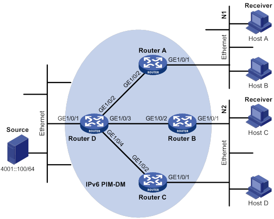
Table 25 Interface and IPv6 address assignment
|
Interface |
IPv6 address |
Device |
Interface |
IPv6 address |
|
|
Router A |
GE1/0/1 |
1001::1/64 |
Router C |
GE1/0/2 |
3001::1/64 |
|
Router A |
GE1/0/2 |
1002::1/64 |
Router D |
GE1/0/1 |
4001::1/64 |
|
Router B |
GE1/0/1 |
2001::1/64 |
Router D |
GE1/0/2 |
1002::2/64 |
|
Router B |
GE1/0/2 |
2002::1/64 |
Router D |
GE1/0/3 |
2002::2/64 |
|
Router C |
GE1/0/1 |
2001::2/64 |
Router D |
GE1/0/4 |
3001::2/64 |
Configuration procedure
1. Assign an IPv6 address and prefix length to each interface, as shown in Figure 105. (Details not shown.)
2. Configure OSPFv3 on the routers in the IPv6 PIM-DM domain. (Details not shown.)
3. Enable IPv6 multicast routing, MLD, and IPv6 PIM-DM:
# On Router A, enable IPv6 multicast routing.
<RouterA> system-view
[RouterA] ipv6 multicast routing
[RouterA-mrib6] quit
# Enable MLD on GigabitEthernet 1/0/1 (the interface that connects to the stub network).
[RouterA] interface gigabitethernet 1/0/1
[RouterA-GigabitEthernet1/0/1] mld enable
[RouterA-GigabitEthernet1/0/1] quit
# Enable IPv6 PIM-DM on GigabitEthernet 1/0/2.
[RouterA] interface gigabitethernet 1/0/2
[RouterA-GigabitEthernet1/0/2] ipv6 pim dm
[RouterA-GigabitEthernet1/0/2] quit
# Enable IPv6 multicast routing, MLD, and IPv6 PIM-DM on Router B and Router C in the same way Router A is configured. (Details not shown.)
# On Router D, enable IPv6 multicast routing, and enable IPv6 PIM-DM on each interface.
<RouterD> system-view
[RouterD] ipv6 multicast routing
[RouterD-mrib6] quit
[RouterD] interface gigabitethernet 1/0/1
[RouterD-GigabitEthernet1/0/1] ipv6 pim dm
[RouterD-GigabitEthernet1/0/1] quit
[RouterD] interface gigabitethernet 1/0/2
[RouterD-GigabitEthernet1/0/2] ipv6 pim dm
[RouterD-GigabitEthernet1/0/2] quit
[RouterD] interface gigabitethernet 1/0/3
[RouterD-GigabitEthernet1/0/3] ipv6 pim dm
[RouterD-GigabitEthernet1/0/3] quit
[RouterD] interface gigabitethernet 1/0/4
[RouterD-GigabitEthernet1/0/4] ipv6 pim dm
[RouterD-GigabitEthernet1/0/4] quit
Verifying the configuration
# Display IPv6 PIM information on Router D.
[RouterD] display ipv6 pim interface
Interface NbrCnt HelloInt DR-Pri DR-Address
GE1/0/1 0 30 1 FE80::A01:201:1
(local)
GE1/0/2 1 30 1 FE80::A01:201:2
(local)
GE1/0/3 1 30 1 FE80::A01:201:3
(local)
GE1/0/4 1 30 1 FE80::A01:201:4
(local)
# Display IPv6 PIM neighboring relationship on Router D.
[RouterD] display ipv6 pim neighbor
Total Number of Neighbors = 3
Neighbor Interface Uptime Expires Dr-Priority
FE80::A01:101:1 GE1/0/2 00:04:00 00:01:29 1
FE80::B01:102:2 GE1/0/3 00:04:16 00:01:29 1
FE80::C01:103:3 GE1/0/4 00:03:54 00:01:17 1
# Send an MLD report from Host A to join IPv6 multicast group FF0E::101. (Details not shown.)
# Send IPv6 multicast data from IPv6 multicast source 4001::100/64 to IPv6 multicast group FF0E::101. (Details not shown.)
# Display IPv6 PIM multicast routing table information on Router A.
[RouterA] display ipv6 pim routing-table
Total 1 (*, G) entry; 1 (S, G) entry
(*, FF0E::101)
Protocol: pim-dm, Flag: WC
UpTime: 00:01:24
Upstream interface: NULL
Upstream neighbor: NULL
RPF prime neighbor: NULL
Downstream interface(s) information:
Total number of downstreams: 1
1: GigabitEthernet1/0/1
Protocol: mld, UpTime: 00:01:20, Expires: -
(4001::100, FF0E::101)
Protocol: pim-dm, Flag: ACT
UpTime: 00:01:20
Upstream interface: GigabitEthernet1/0/2
Upstream neighbor: FE80::A01:201:1
RPF prime neighbor: FE80::A01:201:2
Downstream interface(s) information:
Total number of downstreams: 1
1: GigabitEthernet1/0/1
Protocol: pim-dm, UpTime: 00:01:20, Expires: -
# Display IPv6 PIM multicast routing table information on Router D.
[RouterD] display ipv6 pim routing-table
Total 0 (*, G) entry; 1 (S, G) entry
(4001::100, FF0E::101)
Protocol: pim-dm, Flag: LOC ACT
UpTime: 00:02:19
Upstream interface: GigabitEthernet1/0/1
Upstream neighbor: NULL
RPF prime neighbor: NULL
Downstream interface(s) information:
Total number of downstreams: 1
1: GigabitEthernet1/0/2
Protocol: pim-dm, UpTime: 00:02:19, Expires: -
The output shows the following information:
· Routers on the SPT path (Router A and Router D) have the correct (S, G) entries.
· Router A has the correct (*, G) entry.
IPv6 PIM-SM non-scoped zone configuration example
Network requirements
As shown in Figure 106:
· OSPFv3 runs on the network.
· VOD streams are sent to receiver hosts in multicast. The receivers of different subnets form stub networks, and a minimum of one receiver host exist in each stub network. The entire IPv6 PIM-SM domain contains only one BSR.
· Host A and Host C are multicast receivers on the stub networks N1 and N2.
· Specify GigabitEthernet 1/0/3 on Router E as a C-BSR and a C-RP. The C-RP is designated to IPv6 multicast group range FF0E::101/64. Specify GigabitEthernet 1/0/2 of Router D as the static RP on all the routers to back up the dynamic RP.
· MLDv1 runs between Router A and N1, and between Router B, Router C, and N2.

Table 26 Interface and IPv6 address assignment
|
Device |
Interface |
IPv6 address |
Device |
Interface |
IPv6 address |
|
Router A |
GE1/0/1 |
1001::1/64 |
Router D |
GE1/0/1 |
4001::1/64 |
|
Router A |
GE1/0/2 |
1002::1/64 |
Router D |
GE1/0/2 |
1002::2/64 |
|
Router A |
GE1/0/3 |
1003::1/64 |
Router D |
GE1/0/3 |
4002::1/64 |
|
Router B |
GE1/0/1 |
2001::1/64 |
Router E |
GE1/0/1 |
3001::2/64 |
|
Router B |
GE1/0/2 |
2002::1/64 |
Router E |
GE1/0/2 |
2002::2/64 |
|
Router C |
GE1/0/1 |
2001::2/64 |
Router E |
GE1/0/3 |
1003::2/64 |
|
Router C |
GE1/0/2 |
3001::1/64 |
Router E |
GE1/0/4 |
4002::2/64 |
Configuration procedure
1. Assign an IPv6 address and prefix length to each interface, as shown in Figure 106. (Details not shown.)
2. Configure OSPFv3 on all routers in the IPv6 PIM-SM domain. (Details not shown.)
3. Enable IPv6 multicast routing, and enable MLD and IPv6 PIM-SM:
# On Router A, enable IPv6 multicast routing.
<RouterA> system-view
[RouterA] ipv6 multicast routing
[RouterA-mrib6] quit
# Enable MLD on GigabitEthernet 1/0/1 (the interface that connects to the stub network).
[RouterA] interface gigabitethernet 1/0/1
[RouterA-GigabitEthernet1/0/1] mld enable
[RouterA-GigabitEthernet1/0/1] quit
# Enable IPv6 PIM-SM on the other interfaces.
[RouterA] interface gigabitethernet 1/0/2
[RouterA-GigabitEthernet1/0/2] ipv6 pim sm
[RouterA-GigabitEthernet1/0/2] quit
[RouterA] interface gigabitethernet 1/0/3
[RouterA-GigabitEthernet 1/0/3] ipv6 pim sm
[RouterA-GigabitEthernet 1/0/3] quit
# Enable IPv6 multicast routing, MLD and IPv6 PIM-SM on Router B and Router C in the same way Router A is configured. (Details not shown.)
# Enable IPv6 multicast routing and IPv6 PIM-SM on Router D and Router E in the same way Router A is configured. (Details not shown.)
4. Configure C-BSRs, C-RPs, and the static RP:
# On Router E, configure the service scope of RP advertisements.
<RouterE> system-view
[RouterE] acl ipv6 basic 2005
[RouterE-acl-ipv6-basic-2005] rule permit source ff0e::101 64
[RouterE-acl-ipv6-basic-2005] quit
# Configure GigabitEthernet 1/0/3 as a C-BSR and a C-RP, and configure GigabitEthernet 1/0/2 of Router D as the static RP.
[RouterE] ipv6 pim
[RouterE-pim6] c-bsr 1003::2
[RouterE-pim6] c-rp 1003::2 group-policy 2005
[RouterE-pim6] static-rp 1002::2
[RouterE-pim6] quit
# On Router A, configure GigabitEthernet 1/0/2 of Router D as the static RP.
[RouterA] ipv6 pim
[RouterA-pim6] static-rp 1002::2
[RouterA-pim6] quit
# Configure a static RP on Router B, Router C, and Router D in the same way Router A is configured. (Details not shown.)
Verifying the configuration
# Display IPv6 PIM information on Router A.
[RouterA] display ipv6 pim interface
Interface NbrCnt HelloInt DR-Pri DR-Address
GE1/0/2 1 30 1 FE80::A01:201:2
GE1/0/3 1 30 1 FE80::A01:201:3
# Display BSR information on Router A.
[RouterA] display ipv6 pim bsr-info
Scope: non-scoped
State: Accept Preferred
Bootstrap timer: 00:01:44
Elected BSR address: 1003::2
Priority: 64
Hash mask length: 126
Uptime: 00:11:18
# Display BSR information on Router E.
[RouterE] display ipv6 pim bsr-info
Scope: non-scoped
State: Elected
Bootstrap timer: 00:01:44
Elected BSR address: 1003::2
Priority: 64
Hash mask length: 126
Uptime: 00:11:18
Candidate BSR address: 1003::2
Priority: 64
Hash mask length: 126
# Display RP information on Router A.
[RouterA] display ipv6 pim rp-info
BSR RP information:
Scope: non-scoped
Group/MaskLen: ff0e:: /64
RP address Priority HoldTime Uptime Expires
1003::2 192 180 00:05:19 00:02:11
Static RP information:
RP address ACL Mode Preferred
1002::2 ---- pim-sm No
IPv6 PIM-SM admin-scoped zone configuration example
Network requirements
As shown in Figure 107:
· OSPFv3 runs on the network. VOD streams are sent to receiver hosts in multicast. The entire IPv6 PIM-SM domain is divided into IPv6 admin-scoped zone 1, IPv6 admin-scoped zone 2, and the IPv6 global-scoped zone. Router B, Router C, and Router D are ZBRs of the three zones, respectively.
· Source 1 and Source 2 send different IPv6 multicast data to the IPv6 multicast group FF14::101. Host A receives the IPv6 multicast data only from Source 1, and Host B receives the IPv6 multicast data only from Source 2. Source 3 sends IPv6 multicast data to IPv6 multicast group FF1E::202. Host C is an IPv6 multicast receiver for IPv6 multicast group FF1E::202.
· GigabitEthernet 1/0/2 of Router B acts as a C-BSR and a C-RP for IPv6 admin-scoped zone 1, and GigabitEthernet 1/0/1 of Router D acts as a C-BSR and a C-RP for IPv6 admin-scoped zone 2. Both of the two interfaces are designated to the IPv6 multicast groups with the scope field of 4. GigabitEthernet 1/0/1 of Router F acts as a C-BSR and a C-RP for the IPv6 global-scoped zone, and is designated to the IPv6 multicast groups with the scope field value of 14.
· MLDv1 separately runs between Router A, Router E, Router I, and the receivers that directly connect to them.
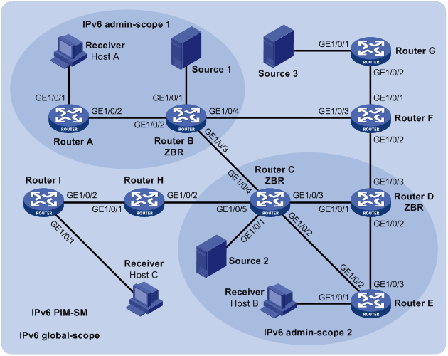
Table 27 Interface and IPv6 address assignment
|
Device |
Interface |
IPv6 address |
Device |
Interface |
IPv6 address |
|
Router A |
GE1/0/1 |
1001::1/64 |
Router E |
GE1/0/2 |
3002::2/64 |
|
Router A |
GE1/0/2 |
1002::1/64 |
Router E |
GE1/0/3 |
6001::2/64 |
|
Router B |
GE1/0/1 |
2001::1/64 |
Router F |
GE1/0/1 |
8001::1/64 |
|
Router B |
GE1/0/2 |
1002::2/64 |
Router F |
GE1/0/2 |
6002::2/64 |
|
Router B |
GE1/0/3 |
2002::1/64 |
Router F |
GE1/0/3 |
2003::2/64 |
|
Router B |
GE1/0/4 |
2003::1/64 |
Router G |
GE1/0/1 |
9001::1/64 |
|
Router C |
GE1/0/1 |
3001::1/64 |
Router G |
GE1/0/2 |
8001::2/64 |
|
Router C |
GE1/0/2 |
3002::1/64 |
Router H |
GE1/0/1 |
4001::1/64 |
|
Router C |
GE1/0/3 |
3003::1/64 |
Router H |
GE1/0/2 |
3004::2/64 |
|
Router C |
GE1/0/4 |
2002::2/64 |
Router I |
GE1/0/1 |
5001::1/64 |
|
Router C |
GE1/0/5 |
3004::1/64 |
Router I |
GE1/0/2 |
4001::2/64 |
|
Router D |
GE1/0/1 |
3003::2/64 |
Source 1 |
— |
2001::100/64 |
|
Router D |
GE1/0/3 |
6001::1/64 |
Source 2 |
— |
3001::100/64 |
|
Router D |
GE1/0/3 |
6002::1/64 |
Source 3 |
— |
9001::100/64 |
|
Router E |
GE1/0/1 |
7001::1/64 |
|
|
|
Configuration procedure
1. Assign an IPv6 address and prefix length to each interface, as shown in Figure 107. (Details not shown.)
2. Configure OSPFv3 on all routers in the IPv6 PIM-SM domain. (Details not shown.)
3. Enable IPv6 multicast routing, MLD, and IPv6 PIM-SM:
# On Router A, enable IPv6 multicast routing.
<RouterA> system-view
[RouterA] ipv6 multicast routing
[RouterA-mrib6] quit
# Enable MLD on the receiver-side interface (GigabitEthernet 1/0/1).
[RouterA] interface gigabitethernet 1/0/1
[RouterA-GigabitEthernet1/0/1] mld enable
[RouterA-GigabitEthernet1/0/1] quit
# Enable IPv6 PIM-SM on GigabitEthernet 1/0/2.
[RouterA] interface gigabitethernet 1/0/2
[RouterA-GigabitEthernet1/0/2] ipv6 pim sm
[RouterA-GigabitEthernet1/0/2] quit
# Enable IPv6 multicast routing, MLD, and IPv6 PIM-SM on Router E and Router I in the same way Router A is configured. (Details not shown.)
# On Router B, enable IPv6 multicast routing, and enable IPv6 PIM-SM on each interface.
<RouterB> system-view
[RouterB] ipv6 multicast routing
[RouterB-mrib6] quit
[RouterB] interface gigabitethernet 1/0/1
[RouterB-GigabitEthernet1/0/1] ipv6 pim sm
[RouterB-GigabitEthernet1/0/1] quit
[RouterB] interface gigabitethernet 1/0/2
[RouterB-GigabitEthernet1/0/2] ipv6 pim sm
[RouterB-GigabitEthernet1/0/2] quit
[RouterB] interface gigabitethernet 1/0/3
[RouterB-GigabitEthernet1/0/3] ipv6 pim sm
[RouterB-GigabitEthernet1/0/3] quit
[RouterB] interface gigabitethernet 1/0/4
[RouterB-GigabitEthernet1/0/4] ipv6 pim sm
[RouterB-GigabitEthernet1/0/4] quit
# Enable IPv6 multicast routing and IPv6 PIM-SM on Router C, Router D, Router F, Router G, and Router H in the same way Router B is configured. (Details not shown.)
4. Configure IPv6 admin-scoped zone boundaries:
# On Router B, configure GigabitEthernet 1/0/3 and GigabitEthernet 1/0/4 as the boundaries of IPv6 admin-scoped zone 1.
[RouterB] interface gigabitethernet 1/0/3
[RouterB-GigabitEthernet1/0/3] ipv6 multicast boundary scope 4
[RouterB-GigabitEthernet1/0/3] quit
[RouterB] interface gigabitethernet 1/0/4
[RouterB-GigabitEthernet1/0/4] ipv6 multicast boundary scope 4
[RouterB-GigabitEthernet1/0/4] quit
# On Router C, configure GigabitEthernet 1/0/4 and GigabitEthernet 1/0/5 as the boundaries of IPv6 admin-scoped zone 2.
<RouterC> system-view
[RouterC] interface gigabitethernet 1/0/4
[RouterC-GigabitEthernet1/0/4] ipv6 multicast boundary scope 4
[RouterC-GigabitEthernet1/0/4] quit
[RouterC] interface gigabitethernet 1/0/5
[RouterC-GigabitEthernet1/0/5] ipv6 multicast boundary scope 4
[RouterC-GigabitEthernet1/0/5] quit
# On Router D, configure GigabitEthernet 1/0/3 as the boundary of IPv6 admin-scoped zone 2.
<RouterD> system-view
[RouterD] interface gigabitethernet 1/0/3
[RouterD-GigabitEthernet1/0/3] ipv6 multicast boundary scope 4
[RouterD-GigabitEthernet1/0/3] quit
5. Configure C-BSRs and C-RPs:
# On Router B, configure GigabitEthernet 1/0/2 as a C-BSR and a C-RP for IPv6 admin-scoped zone 1.
[RouterB] ipv6 pim
[RouterB-pim6] c-bsr 1002::2 scope 4
[RouterB-pim6] c-rp 1002::2 scope 4
[RouterB-pim6] quit
# On Router D, configure GigabitEthernet 1/0/1 as a C-BSR and a C-RP for IPv6 admin-scoped zone 2.
[RouterD] ipv6 pim
[RouterD-pim6] c-bsr 3003::2 scope 4
[RouterD-pim6] c-rp 3003::2 scope 4
[RouterD-pim6] quit
# On Router F, configure GigabitEthernet 1/0/1 as a C-BSR and a C-RP for the IPv6 global-scoped zone.
<RouterF> system-view
[RouterF] ipv6 pim
[RouterF-pim6] c-bsr 8001::1
[RouterF-pim6] c-rp 8001::1
[RouterF-pim6] quit
Verifying the configuration
# Display BSR information on Router B.
[RouterB] display ipv6 pim bsr-info
Scope: non-scoped
State: Accept Preferred
Bootstrap timer: 00:01:25
Elected BSR address: 8001::1
Priority: 64
Hash mask length: 126
Uptime: 00:01:45
Scope: 4
State: Elected
Bootstrap timer: 00:00:06
Elected BSR address: 1002::2
Priority: 64
Hash mask length: 126
Uptime: 00:04:54
Candidate BSR address: 1002::2
Priority: 64
Hash mask length: 126
# Display BSR information on Router D.
[RouterD] display ipv6 pim bsr-info
Scope: non-scoped
State: Accept Preferred
Bootstrap timer: 00:01:25
Elected BSR address: 8001::1
Priority: 64
Hash mask length: 126
Uptime: 00:01:45
Scope: 4
State: Elected
Bootstrap timer: 00:01:25
Elected BSR address: 3003::2
Priority: 64
Hash mask length: 126
Uptime: 00:01:45
Candidate BSR address: 3003::2
Priority: 64
Hash mask length: 126
# Display BSR information on Router F.
[RouterF] display ipv6 pim bsr-info
Scope: non-scoped
State: Elected
Bootstrap timer: 00:00:49
Elected BSR address: 8001::1
Priority: 64
Hash mask length: 126
Uptime: 00:01:11
Candidate BSR address: 8001::1
Priority: 64
Hash mask length: 126
# Display RP information on Router B.
[RouterB] display ipv6 pim rp-info
BSR RP information:
Scope: non-scoped
Group/MaskLen: FF00::/8
RP address Priority HoldTime Uptime Expires
8001::1 192 180 00:01:14 00:02:46
Scope: 4
Group/MaskLen: FF04::/16
RP address Priority HoldTime Uptime Expires
1002::2 (local) 192 180 00:02:03 00:02:56
Group/MaskLen: FF14::/16
RP address Priority HoldTime Uptime Expires
1002::2 (local) 192 180 00:02:03 00:02:56
Group/MaskLen: FF24::/16
RP address Priority HoldTime Uptime Expires
1002::2 (local) 192 180 00:02:03 00:02:56
Group/MaskLen: FF34::/16
RP address Priority HoldTime Uptime Expires
1002::2 (local) 192 180 00:02:03 00:02:56
Group/MaskLen: FF44::/16
RP address Priority HoldTime Uptime Expires
1002::2 (local) 192 180 00:02:03 00:02:56
Group/MaskLen: FF54::/16
RP address Priority HoldTime Uptime Expires
1002::2 (local) 192 180 00:02:03 00:02:56
Group/MaskLen: FF64::/16
RP address Priority HoldTime Uptime Expires
1002::2 (local) 192 180 00:02:03 00:02:56
Group/MaskLen: FF74::/16
RP address Priority HoldTime Uptime Expires
1002::2 (local) 192 180 00:02:03 00:02:56
Group/MaskLen: FF84::/16
RP address Priority HoldTime Uptime Expires
1002::2 (local) 192 180 00:02:03 00:02:56
Group/MaskLen: FF94::/16
RP address Priority HoldTime Uptime Expires
1002::2 (local) 192 180 00:02:03 00:02:56
Group/MaskLen: FFA4::/16
RP address Priority HoldTime Uptime Expires
1002::2 (local) 192 180 00:02:03 00:02:56
Group/MaskLen: FFB4::/16
RP address Priority HoldTime Uptime Expires
1002::2 (local) 192 180 00:02:03 00:02:56
Group/MaskLen: FFC4::/16
RP address Priority HoldTime Uptime Expires
1002::2 (local) 192 180 00:02:03 00:02:56
Group/MaskLen: FFD4::/16
RP address Priority HoldTime Uptime Expires
1002::2 (local) 192 180 00:02:03 00:02:56
Group/MaskLen: FFE4::/16
RP address Priority HoldTime Uptime Expires
1002::2 (local) 192 180 00:02:03 00:02:56
Group/MaskLen: FFF4::/16
RP address Priority HoldTime Uptime Expires
1002::2 (local) 192 180 00:02:03 00:02:56
# Display RP information on Router F.
[RouterF] display ipv6 pim rp-info
BSR RP information:
Scope: non-scoped
Group/MaskLen: FF00::/8
RP address Priority HoldTime Uptime Expires
8001::1 (local) 192 180 00:10:28 00:02:31
IPv6 BIDIR-PIM configuration example
Network requirements
As shown in Figure 108:
· OSPFv3 runs on the network. VOD streams are sent to receiver hosts in IPv6 multicast. Source 1 and Source 2 send multicast data to IPv6 multicast group FF14::101. Host A and Host B are receivers of this IPv6 multicast group.
· GigabitEthernet 1/0/1 of Router C acts as the C-BSR. Loopback 0 of Router C acts as the C-RP.
· MLDv1 runs between Router B and Host A, and between Router D and Host B.
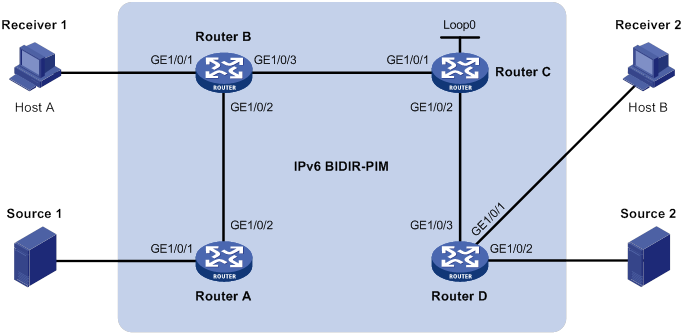
Table 28 Interface and IPv6 address assignment
|
Device |
Interface |
IPv6 address |
Device |
Interface |
IPv6 address |
|
Router A |
GE1/0/1 |
1001::1/64 |
Router D |
GE1/0/1 |
4001::1/64 |
|
Router A |
GE1/0/2 |
1002::1/64 |
Router D |
GE1/0/2 |
5001::1/64 |
|
Router B |
GE1/0/1 |
2001::1/64 |
Router D |
GE1/0/3 |
3001::2/64 |
|
Router B |
GE1/0/2 |
1002::2/64 |
Source 1 |
— |
1001::2/64 |
|
Router B |
GE1/0/3 |
2002::1/64 |
Source 2 |
— |
5001::2/64 |
|
Router C |
GE1/0/1 |
2002::2/64 |
Receiver 1 |
— |
2001::2/64 |
|
Router C |
GE1/0/2 |
3001::1/64 |
Receiver 2 |
— |
4001::2/64 |
|
Router C |
Loop0 |
6001::1/128 |
|
|
|
Configuration procedure
1. Assign an IPv6 address and prefix length to each interface, as shown in Figure 108. (Details not shown.)
2. Configure OSPFv3 on the routers in the IPv6 BIDIR-PIM domain. (Details not shown.)
3. Enable IPv6 multicast routing, IPv6 PIM-SM, IPv6 BIDIR-PIM, and MLD:
# On Router A, enable IPv6 multicast routing, enable IPv6 PIM-SM on each interface, and enable IPv6 BIDIR-PIM.
<RouterA> system-view
[RouterA] ipv6 multicast routing
[RouterA-mrib6] quit
[RouterA] interface gigabitethernet 1/0/1
[RouterA-GigabitEthernet1/0/1] ipv6 pim sm
[RouterA-GigabitEthernet1/0/1] quit
[RouterA] interface gigabitethernet 1/0/2
[RouterA-GigabitEthernet1/0/2] ipv6 pim sm
[RouterA-GigabitEthernet1/0/2] quit
[RouterA] ipv6 pim
[RouterA-pim6] bidir-pim enable
[RouterA-pim6] quit
# On Router B, enable IPv6 multicast routing.
<RouterB> system-view
[RouterB] ipv6 multicast routing
[RouterB-mrib6] quit
# Enable MLD on the receiver-side interface (GigabitEthernet 1/0/1).
[RouterB] interface gigabitethernet 1/0/1
[RouterB-GigabitEthernet1/0/1] mld enable
[RouterB-GigabitEthernet1/0/1] quit
# Enable IPv6 PIM-SM on other interfaces.
[RouterB] interface gigabitethernet 1/0/2
[RouterB-GigabitEthernet1/0/2] ipv6 pim sm
[RouterB-GigabitEthernet1/0/2] quit
[RouterB] interface gigabitethernet 1/0/3
[RouterB-GigabitEthernet1/0/3] ipv6 pim sm
[RouterB-GigabitEthernet1/0/3] quit
# Enable IPv6 BIDIR-PIM.
[RouterB] ipv6 pim
[RouterB-pim6] bidir-pim enable
[RouterB-pim6] quit
# On Router C, enable IPv6 multicast routing, enable IPv6 PIM-SM on each interface, and enable IPv6 BIDIR-PIM.
<RouterC> system-view
[RouterC] ipv6 multicast routing
[RouterC-mrib6] quit
[RouterC] interface gigabitethernet 1/0/1
[RouterC-GigabitEthernet1/0/1] ipv6 pim sm
[RouterC-GigabitEthernet1/0/1] quit
[RouterC] interface gigabitethernet 1/0/2
[RouterC-GigabitEthernet1/0/2] ipv6 pim sm
[RouterC-GigabitEthernet1/0/2] quit
[RouterC] interface loopback 0
[RouterC-LoopBack0] ipv6 pim sm
[RouterC-LoopBack0] quit
[RouterC] ipv6 pim
[RouterC-pim6] bidir-pim enable
# On Router D, enable IPv6 multicast routing.
<RouterD> system-view
[RouterD] ipv6 multicast routing
[RouterD-mrib6] quit
# Enable MLD on the receiver-side interface (GigabitEthernet 1/0/1).
[RouterD] interface gigabitethernet 1/0/1
[RouterD-GigabitEthernet1/0/1] mld enable
[RouterD-GigabitEthernet1/0/1] quit
# Enable IPv6 PIM-SM on the other interfaces.
[RouterD] interface gigabitethernet 1/0/2
[RouterD-GigabitEthernet1/0/2] ipv6 pim sm
[RouterD-GigabitEthernet1/0/2] quit
[RouterD] interface gigabitethernet 1/0/3
[RouterD-GigabitEthernet1/0/3] ipv6 pim sm
[RouterD-GigabitEthernet1/0/3] quit
# Enable IPv6 BIDIR-PIM.
[RouterD] ipv6 pim
[RouterD-pim6] bidir-pim enable
[RouterD-pim6] quit
4. On Router C, configure GigabitEthernet 1/0/1 as the C-BSR, and Loopback 0 as the C-RP for the entire IPv6 BIDIR-PIM domain.
[RouterC-pim6] c-bsr 2002::2
[RouterC-pim6] c-rp 6001::1 bidir
[RouterC-pim6] quit
Verifying the configuration
1. Display the DF information of BIDIR-PIM:
# Display the DF information of IPv6 BIDIR-PIM on Router A.
[RouterA] display ipv6 pim df-info
RP address: 6001::1
Interface: GigabitEthernet1/0/1
State : Win DF preference: 100
DF metric : 2 DF uptime : 00:07:15
DF address: FE80::200:5EFF: FE71:2800 (local)
Interface: GigabitEthernet1/0/2
State : Lose DF preference: 100
DF metric : 1 DF uptime : 00:07:15
DF address: FE80::20F:E2FF: FE38:4E01
# Display the DF information of IPv6 BIDIR-PIM on Router B.
[RouterB] display ipv6 pim df-info
RP address: 6001::1
Interface: GigabitEthernet1/0/2
State : Win DF preference: 100
DF metric : 1 DF uptime : 00:07:15
DF address: FE80::20F:E2FF: FE38:4E01 (local)
Interface: GigabitEthernet1/0/3
State : Lose DF preference: 0
DF metric : 0 DF uptime : 00:07:15
DF address: FE80::20F:E2FF: FE15:5601
# Display the DF information of IPv6 BIDIR-PIM on Router C.
[RouterC] display ipv6 pim df-info
RP address: 6001::1
Interface: Loop0
State : - DF preference: -
DF metric : - DF uptime : -
DF address: -
Interface: GigabitEthernet1/0/1
State : Win DF preference: 0
DF metric : 0 DF uptime : 00:07:15
DF address: FE80::20F:E2FF: FE15:5601 (local)
Interface: GigabitEthernet1/0/2
State : Lose DF preference: 0
DF metric : 0 DF uptime : 00:07:15
DF address: FE80::20F:E2FF: FE15:5602 (local)
# Display the DF information of IPv6 BIDIR-PIM on Router D.
[RouterD] display ipv6 pim df-info
RP address: 6001::1
Interface: GigabitEthernet1/0/2
State : Win DF preference: 100
DF metric : 1 DF uptime : 00:07:15
DF address: FE80::200:5EFF: FE71:2802 (local)
Interface: GigabitEthernet1/0/3
State : Lose DF preference: 0
DF metric : 0 DF uptime : 00:07:15
DF address: FE80::20F:E2FF: FE15:5602 (local)
2. Display information about the DF for IPv6 multicast forwarding:
# Display information about the DF for IPv6 multicast forwarding on Router A.
[RouterA] display ipv6 multicast forwarding df-info
Total 1 RPs, 1 matched
00001. RP address: 6001::1
Flags: 0x0
Uptime: 00:08:32
RPF interface: GigabitEthernet1/0/2
List of 1 DF interfaces:
1: GigabitEthernet1/0/1
# Display information about the DF for IPv6 multicast forwarding on Router B.
[RouterB] display ipv6 multicast forwarding df-info
Total 1 RPs, 1 matched
00001. RP address: 6001::1
Flags: 0x0
Uptime: 00:06:24
RPF interface: GigabitEthernet1/0/3
List of 1 DF interfaces:
1: GigabitEthernet1/0/2
# Display information about the DF for IPv6 multicast forwarding on Router C.
[RouterC] display ipv6 multicast forwarding df-info
Total 1 RPs, 1 matched
00001. RP address: 6001::1
Flags: 0x0
Uptime: 00:07:21
RPF interface: LoopBack0
List of 2 DF interfaces:
1: GigabitEthernet1/0/1
2: GigabitEthernet1/0/2
# Display information about the DF for IPv6 multicast forwarding on Router D.
[RouterD] display ipv6 multicast forwarding df-info
Total 1 RPs, 1 matched
00001. RP address: 6001::1
Flags: 0x0
Uptime: 00:05:12
RPF interface: GigabitEthernet1/0/3
List of 1 DF interfaces:
1: GigabitEthernet1/0/2
IPv6 PIM-SSM configuration example
Network requirements
As shown in Figure 109:
· OSPFv3 runs on the network.
· The receivers receive VOD information through multicast. The receiver groups of different organizations form stub networks, and one or more receiver hosts exist in each stub network. The entire IPv6 PIM domain operates in the SSM mode.
· Host A and Host C are IPv6 multicast receivers in two stub networks, N1 and N2.
· The SSM group range is FF3E::/64.
· MLDv2 runs between Router A and N1, and between Router B, Router C, and N2.
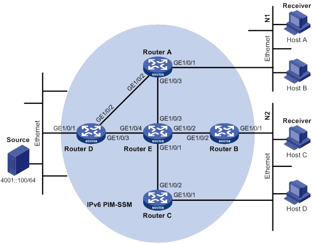
Table 29 Interface and IPv6 address assignment
|
Interface |
IPv6 address |
Device |
Interface |
IPv6 address |
|
|
Router A |
GE1/0/1 |
1001::1/64 |
Router D |
GE1/0/1 |
4001::1/64 |
|
Router A |
GE1/0/2 |
1002::1/64 |
Router D |
GE1/0/2 |
1002::2/64 |
|
Router A |
GE1/0/3 |
1003::1/64 |
Router D |
GE1/0/3 |
4002::1/64 |
|
Router B |
GE1/0/1 |
2001::1/64 |
Router E |
GE1/0/1 |
3001::2/64 |
|
Router B |
GE1/0/2 |
2002::1/64 |
Router E |
GE1/0/2 |
2002::2/64 |
|
Router C |
GE1/0/1 |
2001::2/64 |
Router E |
GE1/0/3 |
1003::2/64 |
|
Router C |
GE1/0/2 |
3001::1/64 |
Router E |
GE1/0/4 |
4002::2/64 |
Configuration procedure
1. Assign an IPv6 address and prefix length for each interface, as shown in Figure 109. (Details not shown.)
2. Configure OSPFv3 on the routers in the IPv6 PIM-SSM domain. (Details not shown.)
3. Enable IPv6 multicast routing, MLD and IPv6 PIM-SM:
# On Router A, enable IPv6 multicast routing.
<RouterA> system-view
[RouterA] ipv6 multicast routing
[RouterA-mrib6] quit
# Enable MLDv2 on GigabitEthernet 1/0/1 (the interface that connects to the stub network).
[RouterA] interface gigabitethernet 1/0/1
[RouterA-GigabitEthernet1/0/1] mld enable
[RouterA-GigabitEthernet1/0/1] mld version 2
[RouterA-GigabitEthernet1/0/1] quit
# Enable IPv6 PIM-SM on other interfaces.
[RouterA] interface gigabitethernet 1/0/2
[RouterA-GigabitEthernet1/0/2] ipv6 pim sm
[RouterA-GigabitEthernet1/0/2] quit
[RouterA] interface gigabitethernet 1/0/3
[RouterA-GigabitEthernet1/0/3] ipv6 pim sm
[RouterA-GigabitEthernet1/0/3] quit
# Enable IPv6 multicast routing, MLD and IPv6 PIM-SM on Router B and Router C in the same way Router A is configured. (Details not shown.)
# Enable IPv6 multicast routing and IPv6 PIM-SM on Router D and Router E in the same way Router A is configured. (Details not shown.)
4. Configure the IPv6 SSM group range FF3E::/64 on Router A.
[RouterA] acl ipv6 basic 2000
[RouterA-acl-ipv6-basic-2000] rule permit source ff3e:: 64
[RouterA-acl-ipv6-basic-2000] quit
[RouterA] ipv6 pim
[RouterA-pim6] ssm-policy 2000
[RouterA-pim6] quit
5. Configure the IPv6 SSM group range on Router B, Router C, Router D and Router E in the same way Router A is configured. (Details not shown.)
Verifying the configuration
# Display IPv6 PIM information on Router A.
[RouterA] display ipv6 pim interface
Interface NbrCnt HelloInt DR-Pri DR-Address
GE1/0/2 1 30 1 FE80::A01:201:2
GE1/0/3 1 30 1 FE80::A01:201:3
# Send an MLDv2 report from Host A to join IPv6 multicast source and group (4001::100/64, FF3E::101). (Details not shown.)
# Display IPv6 PIM multicast routing table information on Router A.
[RouterA] display ipv6 pim routing-table
Total 0 (*, G) entry; 1 (S, G) entry
(4001::100, FF3E::101)
Protocol: pim-ssm, Flag:
UpTime: 00:00:11
Upstream interface: GigabitEthernet1/0/2
Upstream neighbor: FE80::A01:201:2
RPF prime neighbor: FE80::A01:201:3
Downstream interface(s) information:
Total number of downstreams: 1
1: GigabitEthernet1/0/1
Protocol: mld, UpTime: 00:00:11, Expires: 00:03:25
# Display IPv6 PIM multicast routing table information on Router D.
[RouterD] display ipv6 pim routing-table
Total 0 (*, G) entry; 1 (S, G) entry
(4001::100, FF3E::101)
Protocol: pim-ssm, Flag: LOC
UpTime: 00:08:02
Upstream interface: GigabitEthernet1/0/1
Upstream neighbor: NULL
RPF prime neighbor: NULL
Downstream interface(s) information:
Total number of downstreams: 1
1: GigabitEthernet1/0/2
Protocol: pim-ssm, UpTime: 00:08:02, Expires: 00:03:25
The output shows that routers on the SPT path (Router A and Router D) have generated the correct (S, G) entries.
Troubleshooting IPv6 PIM
A multicast distribution tree cannot be correctly built
Symptom
No IPv6 multicast forwarding entries are established on the routers (including routers directly connected with multicast sources or receivers) in an IPv6 PIM network. This means that an IPv6 multicast distribution tree cannot be correctly built.
Solution
To resolve the problem:
1. Use display ipv6 routing-table to verify that an IPv6 unicast route to the IPv6 multicast source or the RP is available.
2. Use display ipv6 pim interface to verify IPv6 PIM information on each interface, especially on the RPF interface. If IPv6 PIM is not enabled on the interfaces, use ipv6 pim dm or ipv6 pim sm to enable IPv6 PIM-DM or IPv6 PIM-SM for the interfaces.
3. Use display ipv6 pim neighbor to verify that the RPF neighbor is an IPv6 PIM neighbor.
4. Verify that IPv6 PIM and MLD are enabled on the interfaces that directly connect to the IPv6 multicast sources or the receivers.
5. Use display ipv6 pim interface verbose to verify that the same IPv6 PIM mode is enabled on the RPF interface on a router and the connected interface of the router's RPF neighbor.
6. Use display current-configuration to verify that the same IPv6 PIM mode is enabled on all routers on the network. For IPv6 PIM-SM, verify that the BSR and C-RPs are correctly configured.
7. If the problem persists, contact H3C Support.
IPv6 multicast data is abnormally terminated on an intermediate router
Symptom
An intermediate router can receive IPv6 multicast data successfully, but the data cannot reach the last-hop router. An interface on the intermediate router receives IPv6 multicast data but does not create an (S, G) entry in the IPv6 PIM routing table.
Solution
To resolve the problem:
1. Use display current-configuration to verify the IPv6 multicast forwarding boundary settings. Use ipv6 multicast boundary to change the multicast forwarding boundary settings to make the IPv6 multicast packet able to cross the boundary.
2. Use display current-configuration to verify the IPv6 multicast source policy. Change the ACL rule defined in the source-policy command so that the source/group address of the IPv6 multicast data can pass ACL filtering.
3. If the problem persists, contact H3C Support.
An RP cannot join an SPT in IPv6 PIM-SM
Symptom
An RPT cannot be correctly built, or an RP cannot join the SPT toward the IPv6 multicast source.
Solution
To resolve the problem:
1. Use display ipv6 routing-table to verify that an IPv6 unicast route to the RP is available on each router.
2. Use display ipv6 pim rp-info to verify that the dynamic RP information is consistent on all routers.
3. Use display ipv6 pim rp-info to verify that the same static RPs are configured on all routers on the network.
4. If the problem persists, contact H3C Support.
An RPT cannot be built or IPv6 multicast source registration fails in IPv6 PIM-SM
Symptom
The C-RPs cannot unicast advertisement messages to the BSR. The BSR does not advertise BSMs containing C-RP information and has no IPv6 unicast route to any C-RP. An RPT cannot be correctly established, or the source-side DR cannot register the IPv6 multicast source with the RP.
Solution
To resolve the problem:
1. Use display ipv6 routing-table on each router to view routing table information. Verify that IPv6 unicast routes to the C-RPs and the BSR are available on each router and that a route is available between each C-RP and the BSR.
2. Use display ipv6 pim bsr-info to verify that the BSR information exists on each router.
3. Use display ipv6 pim rp-info to verify that the RP information is correct on each router.
4. Use display ipv6 pim neighbor to verify that IPv6 PIM neighboring relationship has been correctly established among the routers.
5. If the problem persists, contact H3C Support.
Adjusting IGMP performance,72
Adjusting MLD performance,312
Compatibility information,44
Compatibility information,261
Compatibility information,289
Compatibility information,15
Configuring an MSDP peering connection,154
Configuring basic IGMP features,70
Configuring basic IGMP snooping features,17
Configuring basic MLD features,310
Configuring basic MLD snooping features,263
Configuring basic MSDP features,152
Configuring BGP MDT,200
Configuring BIDIR-PIM,112
Configuring common IPv6 PIM features,358
Configuring common PIM features,118
Configuring IGMP proxying,75
Configuring IGMP snooping policies,26
Configuring IGMP snooping port features,19
Configuring IGMP SSM mappings,75
Configuring IPv6 BIDIR-PIM,352
Configuring IPv6 multicast routing and forwarding,290
Configuring IPv6 PIM-DM,343
Configuring IPv6 PIM-SM,345
Configuring IPv6 PIM-SSM,357
Configuring MD VPN,195
Configuring MLD proxying,315
Configuring MLD snooping policies,272
Configuring MLD snooping port features,265
Configuring MLD SSM mappings,315
Configuring multicast routing and forwarding,45
Configuring parameters for IGMP messages,24
Configuring parameters for MLD messages,270
Configuring PIM-DM,103
Configuring PIM-SM,105
Configuring PIM-SSM,117
Configuring SA message-related parameters,156
Configuring the IGMP snooping querier,22
Configuring the MLD snooping querier,268
Displaying and maintaining IGMP,78
Displaying and maintaining IGMP snooping,29
Displaying and maintaining IPv6 multicast routing and forwarding,292
Displaying and maintaining IPv6 PIM,365
Displaying and maintaining MLD,317
Displaying and maintaining MLD snooping,276
Displaying and maintaining MSDP,159
Displaying and maintaining multicast routing and forwarding,48
Displaying and maintaining multicast VPN,202
Displaying and maintaining PIM,125
Enabling IGMP NSR,77
Enabling IP multicast routing,45
Enabling IPv6 multicast routing,290
Enabling MLD NSR,317
Feature and hardware compatibility,69
Feature and hardware compatibility,342
Feature and hardware compatibility,102
Feature and hardware compatibility,152
Feature and hardware compatibility,194
Feature and hardware compatibility,310
How MD VPN works,182
IGMP configuration examples,78
IGMP configuration task list,70
IGMP snooping configuration examples,32
IGMP snooping configuration task list,16
Introduction to multicast,1
IPv6 multicast routing and forwarding configuration examples,295
IPv6 multicast routing and forwarding configuration task list,290
IPv6 PIM configuration examples,366
MLD configuration examples,318
MLD configuration task list,310
MLD snooping configuration examples,278
MLD snooping configuration task list,262
MSDP configuration examples,159
MSDP configuration task list,152
Multicast architecture,5
Multicast models,4
Multicast packet forwarding mechanism,10
Multicast routing and forwarding configuration examples,50
Multicast routing and forwarding configuration task list,45
Multicast support for VPNs,10
Multicast VPN configuration examples,203
Multicast VPN configuration task list,195
Overview,305
Overview,64
Overview,258
Overview,40
Overview,327
Overview,12
Overview,146
Overview,287
Overview,178
Overview,87
PIM configuration examples,126
Troubleshooting IGMP,85
Troubleshooting IGMP snooping,39
Troubleshooting IPv6 PIM,385
Troubleshooting MD VPN,257
Troubleshooting MLD,325
Troubleshooting MLD snooping,286
Troubleshooting MSDP,176
Troubleshooting multicast routing and forwarding,63
Troubleshooting PIM,143