- Table of Contents
- Related Documents
-
| Title | Size | Download |
|---|---|---|
| 01-Text | 712.16 KB |
Configuring POS terminal access
POS application template connection modes
Cascade mode of POS access devices
Configuring caller ID prefixes
POS terminal packet statistics
POS application template handshaking
Feature and hardware compatibility
POS access configuration task list
Enabling the POS access service
Configuring a POS terminal template
Configuring a POS application template
Configuring the POS application mapping table
Configuring POS terminal packet statistics
Configuring FCM interface parameters
Enabling SNMP notifications for POS access
Configuring the POS terminal concurrent connection threshold
Configuring the TCP concurrent transaction threshold
Configuring the transaction timeout
Configuring the alarm threshold for the low NII transaction success rate
Configuring the alarm threshold for the low E1 dialing success rate
Displaying and maintaining POS access
POS access configuration examples
POS dial-up terminal and TCP application configuration example (using an FCM interface)
POS flow terminal and flow application configuration example
POS TCP terminal and TCP application configuration example
POS SSL-based TCP terminal and TCP application configuration example
POS access devices cascade mode configuration example
Backup FEP configuration example (nontransparent mode)
Backup FEP configuration example (transparent mode)
Configuring RTC terminal access
Typical applications of RTC terminal access
RTC terminal access feature list
RTC terminal access specifications
Feature and hardware compatibility
RTC terminal access configuration task list
Configuring the asynchronous TCP RTC one-to-one initiator (TCP_11_Client)
Basic TCP_11_Client configuration
Advanced TCP_11_Client configuration
Configuring the asynchronous TCP RTC one-to-one receiver (TCP_11_Server)
Basic TCP_11_Server configuration
Advanced TCP_11_Server configuration
Configuring the TCP RTC many-to-one relay server (TCP_N1_Server)
Configuring the synchronous UDP RTC one-to-one initiator (UDP_11_Client)
Configuring the synchronous UDP RTC one-to-one receiver (UDP_11_Server)
Configuring the synchronous UDP RTC one-to-many receiver (UDP_1N_Server)
Displaying and maintaining RTC terminal access
RTC terminal access configuration examples
Asynchronous TCP RTC one-to-one configuration example
Synchronous TCP RTC one-to-one configuration example
Asynchronous RTC VPNs configuration example
Asynchronous TCP RTC many-to-one relay configuration example
Synchronous TCP RTC many-to-one relay configuration example
UDP RTC one-to-one backup link configuration example
UDP RTC one-to-many configuration example
Troubleshooting RTC terminal access
Failure to establish a terminal connection
Powered terminal state goes down after terminal access is enabled
Configuring POS terminal access
Overview
The point of sale (POS) access service is a smart card service. It enables a POS terminal to access a bank card accounting system.
Basic concepts
POS terminal
A POS terminal refers to a POS terminal device in this chapter.
POS access device
A POS access device is a router responsible for the datagram forwarding between POS terminals and a bank front-end processor (FEP).
POS application
A POS application is a logical concept on the FEP. It identifies an application on the FEP.
POS terminal template
A POS terminal template is a logical concept on the POS access device. It stores the configuration for a POS terminal on the POS access device.
· The TCP access POS terminal template stores the port number for listening to the terminal packets on the router.
· The dial-up or flow access POS terminal template stores the router interface connected to the POS terminal, such as FCM 2/0/1.
POS application template
A POS application template stores the configuration for a POS application on the POS access device.
· When the connection mode of a POS application template is TCP, the template stores the IP and TCP port number of the FEP.
· When the connection mode of a POS application template is flow, the template stores the router interface connected to the FEP, such as Async 2/2/0.
Application mapping table
The application mapping table stores the maps between the TPDU originator and destination addresses and the application template ID. With this table, the POS access device finds the correct application template according to the TPDU originator and destination addresses in a packet received from a POS terminal. Then, the device sends the packet to the FEP.
Instance
Instance includes POS terminal instance for the POS terminal connection and POS application instance for the POS application connection. It stores the connection information dynamically. Instances inherit the parameters configuration of a template.
· For a TCP access POS terminal template, a TCP connection is referred to as an instance for the terminal template, and a terminal template can have multiple instances.
· For a dial-up or flow access POS terminal, a physical link is referred to as an instance for the terminal template, and each terminal template can have only one instance.
· For a POS application template using TCP connection mode, a TCP connection is referred to as an instance for the application template, and an application template can have multiple instances.
· For a POS application using flow connection mode, a physical link is referred to as an instance for the application template, and each application template can have only one instance.
For information about POS access modes and POS connection modes, see "POS terminal access modes" and "POS application template connection modes."
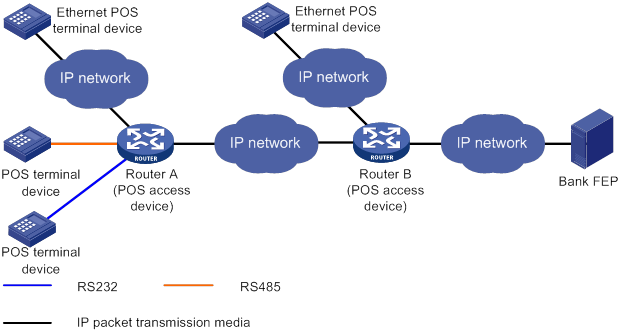
POS terminal access modes
A POS terminal can be connected to the POS access device through dial-up access, flow access, or TCP access.
POS dial-up access
The POS dial-up access procedure uses the following process:
1. A POS terminal detects a card operation.
2. The POS terminal synchronously or asynchronously dials up with the built-in modem to establish a connection to an AM interface or FCM interface on the router (the POS access device).
The Fast Connect Modem (FCM) card is designed for fast POS dial-up access. In synchronous dial-up mode, the FCM card can establish a dial-up connection for a POS terminal in a short time.
3. The router establishes a connection to the bank FEP directly or over a WAN.
The FEP is a remote Unix/Linux server that receives packets and sends replies to the POS terminal.
4. The POS terminal accesses the bank card accounting system over the connection.
Figure 1 Network diagram
POS flow access
In POS flow access mode, the router providing POS access service is located at the commercial client side and helps all POS terminals to access the router. Figure 2 shows a typical network diagram for the POS flow access mode.
The POS flow access mode has the following advantages:
· Over 10 km (6.21 mi) connection distance (with long-line drivers).
· Fast connection rate from POS terminals to the transaction center.
· Fewer occupied communication links and reduced communication costs.
· No service queuing because each POS terminal uses a dedicated line (except networks consisting of POS concentrator and POS terminals).
In POS flow access mode, the following methods are available for connecting a POS terminal to the router:
· Method 1—Directly connect the RS-232 interface of the POS terminal to the asynchronous interface (including the synchronous/asynchronous interface in asynchronous mode) on the router. If the connection distance is longer than 15 m (49.21 ft), you must equip each connection end with a long-line-driver to extend the connection distance.
The operating distance of a pair of passive long-line-drivers is typically about 1200 m (3937.01 ft).
· Method 2—Use multiple POS terminals and a POS concentrator. Connect the RS-232 interface of the POS concentrator to the asynchronous interface of the router.
The configurations for the egress interface of the router are the same for both methods. The second method saves interface resources.
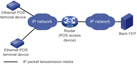
POS TCP access
This mode is applicable to Ethernet POS terminal access. A POS terminal uses its Ethernet interface to connect to the Ethernet interface of the router or of the embedded switching module. In this mode, the router requests an internal transaction number for each packet received from a POS terminal. The router uses the internal transaction number to uniquely identify a connection request and its reply:
1. The router encapsulates the internal transaction number into the packet sent to the FEP.
2. The router extracts the internal transaction number from the reply packet and uses the number to find the corresponding POS terminal.
The POS TCP access mode has the following advantages:
· Long communication distance.
· Fast connection rate from POS terminals to the transaction center.
· Reduced workload on the FEP because not all POS terminals need to establish dedicated TCP/IP connections to the FEP.
Figure 3 Network diagram for POS TCP access
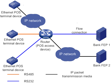
POS application template connection modes
A POS application template communicates with an FEP either through a TCP connection or a flow connection, depending on the connection mode of the FEP to the POS access device.
Upon receiving a packet from a POS terminal, the POS access device processes the packets as follows:
· Encapsulates the packet according to the connection mode of the corresponding POS application template.
· Sends the resulting packet to the FEP.
TCP connection mode
In TCP connection mode, a POS application template communicates with the FEP through a TCP connection. A POS application is identified by an IP address and a port number on the FEP.
The TCP connection modes for POS application templates include permanent TCP connection mode and temporary TCP connection mode.
· Permanent TCP connection mode—The router (POS access device) uses the same TCP connection for transactions of POS terminals. In this mode, a TCP connection does not actively terminate after being established. When a POS terminal sends transaction data to the router for the first time, the router establishes a TCP connection to the FEP, and transfers the data to the FEP through the TCP connection. After the first transaction completes, the TCP connection is maintained, and is used to transfer data from subsequent transactions.
· Temporary TCP connection mode—The router uses a separate TCP connection for each transaction of POS terminals. In this mode, a TCP connection is terminated when a transaction completes, and another TCP connection will be established for a new transaction.
Flow connection mode
In flow connection mode, a POS application template is bound to an asynchronous interface through commands. One application corresponds to one asynchronous interface.
Figure 4 Network diagram of POS application connections
Cascade mode of POS access devices
You can also connect POS terminals to POS access devices in cascade mode, as shown in Figure 5.
Figure 5 Cascade mode of POS access devices
In cascade mode, packets from POS terminals to the FEP are processed by Router A and then by Router B.
· For Router A, Router B acts as the FEP using TCP connection mode.
· For Router B, Router A acts as an Ethernet POS terminal device.
To use the cascade mode:
· Establish TCP connections between Router A and Router B.
· Use temporary or permanent TCP connection mode for POS applications on Router A.
TPDU
· ID—One byte. It identifies the TPDU type. Typically, the correct packet type is 0x60. The incorrect packet type is 0x68.
· Destination Address—Two bytes, also called the Network International Identifier (NII). It indicates the destination address of the packet. Typically, the address is assigned by the transaction center to identify the FEP of a bank.
· Originator Address—Two bytes. It identifies the POS terminal device.
For the reply packet of a POS packet, the originator address and destination address in the TPDU header are reversed.
TPDU address change policy
Before the router forwards a packet from a POS terminal that uses TCP or FCM to an FEP, it changes an address in the TPDU field to a cookie. Upon receiving a response from the FEP, the router forwards the response to the corresponding POS terminal according to the cookie in the response.
FEPs require either the TPDU header's originator or destination address to change. Determine the TPDU address change policy according to the requirements of FEPs.
Router operation modes
The router may operate in transparent or nontransparent mode.
Transparent mode
POS terminals might send out packets that do not follow the TPDU format. You must use transparent mode to transmit this type of packets. Otherwise, the packets are discarded.
The transparent mode does not support the flow connection mode between a POS application template and an FEP.
The transparent mode supports FEP backup. For more information, see "FEP backup."
Nontransparent mode
In nontransparent mode, the router checks the format of each packet received from a POS terminal. If a packet does not follow the TPDU format, the router discards the packet. If a packet is valid, the router uses a POS application template based on the originator and destination addresses in the TPDU header. The router then sends the packet to an FEP according to the application template.
In nontransparent mode, the router can use the same TCP connection for multiple POS terminals to communicate with the FEP.
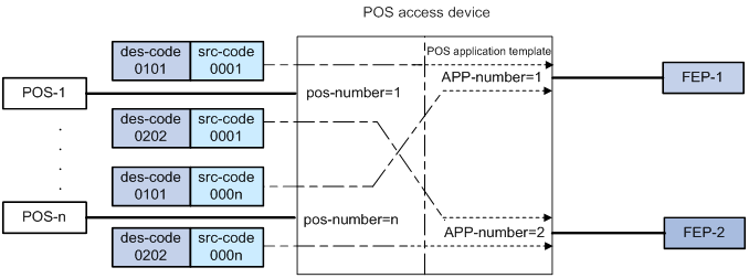
POS application mapping
The router uses the POS application mapping table to send packets from POS terminals to different FEPs The router sends packets according to the originator address and destination address in the TPDU header of the packets.
The router must operate in nontransparent mode to implement POS application mapping. Figure 6 shows a typical example of application mapping.
Figure 6 POS application mapping (FEPs connected to the POS access device through Ethernet)
Sending caller IDs
Enable sending of caller IDs on the router for FEPs that use caller IDs in received packets to identify POS dial-up terminals. This feature is supported only for POS dial-up terminals that are connected to an AM or FCM interface on the router.
Upon receiving packets from a POS dial-up terminal connected to an AM interface, the router first sends the caller ID of the POS terminal to the FEP. After receiving a response from the FEP, the router forwards the packets to the POS terminal.
Upon receiving packets from a POS dial-up terminal connected to an FCM interface, the router adds the caller ID to the header of each packet before sending them to the FEP.
Sending caller IP addresses
The following matrix shows the feature and hardware compatibility:
Table 1 Feature and hardware compatibility
|
Hardware |
Caller IP address sending compatibility |
|
MSR810/810-W/810-W-DB/810-LM/810-W-LM/810-10-PoE/810-LM-HK/810-W-LM-HK/810-LMS/810-LUS |
No |
|
MSR2600-6-X1/2600-10-X1 |
No |
|
MSR 2630 |
Yes |
|
MSR3600-28/3600-51 |
Yes |
|
MSR3600-28-SI/3600-51-SI |
No |
|
MSR3610-X1/3610-X1-DP/3610-X1-DC/3610-X1-DP-DC |
Yes |
|
MSR 3610/3620/3620-DP/3640/3660 |
Yes |
|
MSR5620/5660/5680 |
Yes |
Enable sending of caller IP addresses on the router if the FEP requires IP addresses of POS terminals. Upon receiving a packet from a POS terminal, the router adds the POS terminal's IP address to the packet header before sending the packet to the FEP. Then, the FEP can obtain the IP address of the POS terminal (the caller) from the packet.
Configuring caller ID prefixes
This feature is supported only on the HMIM-1E1POS and DHMIM-1E1POS1DM interface modules.
Configure caller ID prefixes on the router for FEPs that use caller ID prefixes in received packets to identify locations of POS terminals.
This feature takes effect only after sending of caller IDs is enabled.
POS terminal packet statistics
POS terminal statistics include the counts of received, sent, and error packets. The router can collect and classify the statistics based on source IP addresses, caller IDs, terminal templates, application templates, FCM interfaces, NIIs, or E1POS interfaces. You can view these statistics on the MIB platform.
Statistics based on source IP addresses
This method collects statistics for POS terminals using TCP access. When POS terminals transact with FEPs, the router counts the POS packets based on the terminal source IP addresses. You must specify the source IP statistical items for the statistics. The source IP or IP segments in the source IP statistical items can overlap each other or be the same. POS terminal packets that match multiple IP statistical items are counted.
For example, the following are source IP statistical item definitions:
· A: Caller-IP = 192.168.0.0, mask = 255.255.0.0
· B: Caller-IP = 192.168.1.0, mask = 255.255.255.0
· C: Caller-IP = 192.167.0.0, mask = 255.255.0.0
When a POS terminal sends packets with source IP address 192.168.1.2, the packets are counted for both item A and item B.
Statistics based on caller IDs
This method collects statistics for POS terminals that do not use TCP access. When POS terminals transact with the FEPs, the router counts the packets based on the configured caller IDs. Only packets matching the caller IDs are counted.
For example, the following are caller ID definitions:
A: Caller-ID = 82770009
B: Caller-ID = 82770008
C: Caller-ID = 82770007
To be counted in B, POS terminal packets must have the caller ID 82770008.
Statistics based on terminal templates
This method collects statistics only for packets exchanged with POS terminals. The statistics include the counts for the following items:
· Received packets, sent packets, and error packets.
· Error packets due to application mapping failures.
· Discarded packets due to full buffer.
· Discarded packets due to link failures.
· Announce packets sent to POS terminals from the router.
Statistics collection for a terminal template applies to all instances that use the terminal template.
Statistics based on application templates
This method collects statistics only for packets exchanged with FEPs. The statistics include the counts for the following items:
· Received packets, sent packets, and error packets.
· Error packets due to distributing and processing failures.
· Discarded packets due to full buffer.
· Discarded packets due to link failures.
Statistics collection for an application template applies to all instances that use the application template.
Statistics based on FCM interfaces
This method collects statistics for POS terminals connected to FCM interfaces. The statistics include the numbers of total transactions, successful transactions, failed transactions due to dial-up negotiation failures, and disconnection transactions due to timeouts. A transaction is regarded as successful only when an FCM interface receives data from a POS terminal and sends a reply to the terminal. If a link timeout occurs after several packets are processed successfully for a transaction, the number of successful transactions and the number of disconnected transactions each increase by one.
Statistics based on NIIs
This method collects statistics for NII transactions. The statistics for an NII include the counts for the following items:
· Total transactions.
· Packets received from the FEP.
· Packets sent to the FEP.
· Successful transactions.
· Transaction success rate.
Statistics based on E1POS interfaces
An E1POS interface can be channelized into 30 FCM subinterfaces.
This method collects statistics for POS terminals connected to FCM subinterfaces of an E1POS interface. The statistics include the counts for the following items:
· Total transactions.
· Successful transactions.
· Failed transactions due to dial-up negotiation failures.
· Disconnected transactions due to timeouts.
A transaction is regarded as successful only when an FCM subinterface receives data from a POS terminal and sends a reply to the terminal. If a link timeout occurs after several packets are processed successfully for a transaction, the number of successful transactions and the number of disconnected transactions each increase by one.
FEP backup
If the router cannot reach the FEP because of FEP or link failure, the ongoing transaction fails. To solve this problem, you can configure a backup FEP on the router by using the backup app command.
FEP backup is applicable only to POS TCP access. When a POS terminal launches a transaction, the router tries to establish a TCP connection with the primary or backup FEP, depending on the FEP state. If the FEP is unreachable, the router places the FEP to blocked state and starts a quiet timer. Before the timer expires, the FEP keeps in blocked state. After the timer expires, the router places the FEP to non-blocked state. You can set an individual quiet timer for each FEP.
The router selects an FEP for a transaction by following these selection rules:
· If both the primary and backup FEPs are in non-blocked state, the router initiates a connection with the primary FEP. If the connection fails, with the backup FEP.
· If only one FEP is in non-blocked state, the router initiates a connection with the FEP in non-blocked state. If the connection fails, with the other FEP.
· If both the primary and backup FEPs are in blocked state, the router initiates a connection with the primary FEP first and then with the backup FEP.
If both FEPs are unreachable, the transaction fails. If an FEP fails after a connection is successfully established with the FEP, the transaction fails, and the router does not select the other FEP for this transaction. The router selects an FEP for the next transaction by following the selection rules.
POS application template handshaking
By default, the router communicates with an FEP only when a POS terminal initiates a transaction. If the FEP is faulty, the transaction might fail or be delayed. To solve this problem, you can enable the POS application handshaking function to periodically detect the state of an FEP. This function also allows FEPs to detect the reachability of the router.
This function applies only to POS application templates using TCP connection. The router first initiates a connection to the corresponding FEP for the current application template at a specific interval. When the TCP connection is established, the router sends to the FEP a POS packet with an empty data field. The FEP does not respond to the packet.
· For an application template that uses the temporary TCP connection mode, the router periodically initiates a new connection and sends a packet over the connection. Once the packet is successfully sent, the router breaks the connection.
· For an application template that uses the permanent TCP connection mode, the router does not break the connection but uses the connection to send packets periodically at the interval.
Handshaking changes the state of the current POS application. If the POS application is in blocked state, it will switch to non-blocked state when the handshaking succeeds. If the POS application is in non-blocked state, it will switch to blocked state when the handshaking fails.
Feature and hardware compatibility
|
Hardware |
POS terminal access compatibility |
|
MSR810/810-W/810-W-DB/810-LM/810-W-LM/810-10-PoE/810-LM-HK/810-W-LM-HK/810-LMS/810-LUS |
No |
|
MSR2600-6-X1/2600-10-X1 |
No |
|
MSR 2630 |
Yes |
|
MSR3600-28/3600-51 |
Yes |
|
No |
|
|
MSR3610-X1/3610-X1-DP/3610-X1-DC/3610-X1-DP-DC |
Yes |
|
MSR 3610/3620/3620-DP/3640/3660 |
Yes |
|
MSR5620/5660/5680 |
Yes |
|
Hardware |
POS terminal access compatibility |
|
MSR810-LM-GL |
No |
|
MSR810-W-LM-GL |
No |
|
MSR830-6EI-GL |
No |
|
MSR830-10EI-GL |
No |
|
MSR830-6HI-GL |
No |
|
MSR830-10HI-GL |
No |
|
MSR2600-6-X1-GL |
No |
|
MSR3600-28-SI-GL |
No |
License restrictions
You can install licenses to increase the concurrent transaction threshold for each TCP connection supported by the device. For more information about licenses, see Fundamentals Configuration Guide.
Configuring POS access
POS access configuration task list
|
Tasks at a glance |
|
(Required.) Enabling the POS access service |
|
(Required.) Configuring a POS terminal template |
|
(Required.) Configuring a POS application template |
|
(Required.) Configuring the POS application mapping table |
|
(Optional.) Configuring POS terminal packet statistics |
|
(Optional.) Configuring FCM interface parameters |
|
(Optional.) Enabling SNMP notifications for POS access |
|
(Optional.) Configuring the POS terminal concurrent connection threshold |
|
(Optional.) Configuring the TCP concurrent transaction threshold |
|
(Optional.) Configuring the transaction timeout |
|
(Optional.) Configuring the alarm threshold for the low NII transaction success rate |
|
(Optional.) Configuring the alarm threshold for the low E1 dialing success rate |
Enabling the POS access service
|
Step |
Command |
|
|
1. Enter system view. |
system-view |
N/A |
|
2. Enable the POS access service. |
posa server enable |
By default, the POS terminal access service is disabled. |
Configuring a POS terminal template
The configurations vary with the POS terminal access modes.
Configuring a TCP access POS terminal template
|
Step |
Command |
Remarks |
|
1. Enter system view. |
system-view |
N/A |
|
2. Create a POS terminal template in TCP access mode. |
posa terminal terminal-id type tcp listen-port port [ idle-time time ] [ http | https | ssl ] |
By default, no POS terminal templates in TCP access mode exist. Multiple POS terminal templates cannot use the same listening port. Support for the http keyword depends on the device model (see Table 2). If you specify the https or ssl keyword, execute the posa terminal ssl-server-policy command to specify the SSL server policy that the device uses to establish HTTPS or SSL connections with POS terminals. |
|
3. (Optional.) Set a description for the POS terminal template. |
posa terminal terminal-id description text |
By default, no description is set for a POS terminal template. |
|
4. Return to system view. |
quit |
N/A |
|
5. (Optional.) Enable the automatic shutdown of POS access service when all FEPs are unreachable. |
posa auto-stop-service enable |
By default, the POS access service is not automatically shut down when all FEPs are unreachable. This command enables the router to automatically perform the following operations when all FEPs are unreachable: · Shuts down the listening ports for all TCP-based POS terminal templates. · Sets the access interfaces for all E1POS terminal templates to reply with busy tones. When any of the FEPs becomes reachable, the router automatically performs the following operations: · Opens the listening ports for all TCP-based POS terminal templates. · Stops the busy tone reply for all E1POS terminal templates. An FEP is unreachable when one of the following events occurs: · The router fails to initiate a connection to the FEP, for example, the linking time for the connection expires. · The router is disconnected from the FEP due to the keepalive failure. |
|
6. (Optional.) Configure the TPDU destination address replacement policy. |
posa tpdu-replace match terminal { terminal-id | any } destination { des-code | any } to des-code |
By default, the router does not replace the TPDU destination address. |
|
7. (Optional.) Specify an SSL server policy for TCP-based POS terminal templates. |
By default, no SSL server policy is specified for TCP-based POS terminal templates. Execute this command if you specify the https or ssl keyword of the posa terminal command. The device uses the SSL server policy parameters to establish HTTPS or SSL connections with POS terminals. |
Table 2 The http keyword and hardware compatibility
|
Hardware |
Keyword compatibility |
|
MSR810/810-W/810-W-DB/810-LM/810-W-LM/810-10-PoE/810-LM-HK/810-W-LM-HK/810-LMS/810-LUS |
No |
|
MSR2600-6-X1/2600-10-X1 |
No |
|
MSR 2630 |
Yes |
|
MSR3600-28/3600-51 |
Yes |
|
MSR3600-28-SI/3600-51-SI |
No |
|
MSR3610-X1/3610-X1-DP/3610-X1-DC/3610-X1-DP-DC |
Yes |
|
MSR 3610/3620/3620-DP/3640/3660 |
Yes |
|
MSR5620/5660/5680 |
Yes |
Configuring a flow or dial-up access POS terminal template
To configure a POS terminal template to operate in transparent mode, you must specify a POS application template in the posa bind terminal command. You can specify a nonexistent application template. However, you must create the application template with that ID. As a best practice, configure the application template first. For more information, see "Configuring a POS application template."
To configure a flow or dial-up access POS terminal template:
|
Step |
Command |
Remarks |
|
1. Enter system view. |
system-view |
N/A |
|
2. Configure an interface or subinterfaces of an interface as POS access interfaces. |
· (Method 1) Configure a POS access interface: a. Enter interface view: b. Specify the current interface as a POS access interface: · (Method 2) Configure POS access interfaces in bulk: c. Enter interface view: d. Configure the subinterfaces of the current interface as POS access
interfaces: |
By default, no POS access interfaces are configured. For method 1, the interface can be the following types: · For a flow access POS terminal template, the interface can be a synchronous/asynchronous interface or an asynchronous interface. · For a dial-up access POS terminal template, the interface can be a physical AM interface or physical FCM interface. For method 2, the interface can be the following types: · Channelized AM interface—AM interface channelized from a physical CE1/PRI interface of the PHY_E1DM or PHY_E1POSDM type. · Channelized FCM interface—FCM interface channelized from a physical CE1/PRI interface of the PHY_E1POS or PHY_E1POSDM type. |
|
3. Return to system view. |
quit |
N/A |
|
4. (Optional.) Set FCM parameters for modem negotiation. |
posa fcm { answer-time time1 | idle-time time2 | trade-time time3 } * |
By default: · time1 is 2000 milliseconds. · time2 is 180 seconds. · time3 is 12000000 milliseconds. |
|
5. (Optional.) Set the description of the POS terminal template. |
posa terminal terminal-id description text |
By default, no description is set for a POS terminal template. |
|
6. (Optional.) Configure the TPDU destination address replacement policy. |
posa tpdu-replace match terminal { terminal-id | any } destination { des-code | any } to des-code |
By default, the router does not replace the TPDU destination address. |
Configuring a POS application template
|
Step |
Command |
Remarks |
|
1. Enter system view. |
system-view |
N/A |
|
2. Create a POS application template and enter POS application template view. |
posa app app-id type { flow | tcp } |
By default, no POS application templates exist. |
|
3. (Optional.) Configure a description for the POS application template. |
description text |
By default, no description is configured for the POS application template, and it is displayed as an empty string on the MIB platform. |
|
4. Specify the IP address and port number of an FEP. |
ip ip-address port port-number |
This configuration is required for the POS application template in TCP mode. You can specify only one IP address and port number for a POS application template. Modifying the IP address or port number also removes all existing TCP connections that use this template. |
|
5. Configure the TCP connection mode of the POS application template. |
mode { temporary | permanent } |
By default, the permanent mode is used. If you switch between the permanent and temporary mode, the TCP connections already established by the POS application template are terminated. When POS access devices are connected through TCP in cascade mode, specify the temporary mode for POS application templates between the POS access devices. |
|
6. (Optional.) Configure the TCP keepalive parameters for the POS application template. |
tcp keepalive interval interval count counts |
By default, the value of interval is 2 seconds, and the value of counts is 3. Changes to the keepalive parameters take effect immediately. When the TCP connections are terminated because of the keepalive detection mechanism, it will not trigger the switch between the primary and backup FEP if a backup application template is already specified. |
|
7. (Optional.) Specify the TCP connection timeout. |
tcp linking-time time |
By default, the timeout is 20 seconds. The configuration takes effect only on TCP connections initiated after the configuration. |
|
8. Specify a source IP address for TCP connections. |
source ip ip-address |
By default, no source IP address is specified. Specifying a source IP address removes all existing TCP connections that use this template. |
|
9. Specify a source port number for TCP connections. |
source port port-number |
By default, no source port is specified. Specifying a source port number removes all existing TCP connections that use this template. The specified source port must not be one of the flowing: · Listening port specified for a terminal template. · Source port for any other application template. · Port number for any other system process. If you specify a source port number that is the same as the port number for any other system process, the source port does not take effect. |
|
10. (Optional.) Enable sending of the caller ID. |
caller-number enable |
By default, caller ID sending is disabled. This feature is supported for application templates in TCP mode and for POS dial-up terminals connected to AM or FCM interfaces. For a POS terminal connected to an AM interface, you must enable the modem module in TTY view to obtain the caller ID. For more information, see layer 2—LAN Switching Command Reference. |
|
11. (Optional.) Configure a caller ID prefix. |
posa calling-prefix string |
By default, the router does not add a prefix to caller IDs in packets sent to the FEP. |
|
12. (Optional.) Enable sending of caller IP addresses. |
terminal-ip append |
By default, the caller IP addressing sending feature is disabled. Support for this feature depends on the device model (see Table 1). This feature is applicable only when the POS terminal access mode is TCP. |
|
13. (Optional.) Configure the TPDU address change policy. |
tpdu-change { destination | source } |
By default, the TPDU originator address will be changed. In nontransparent mode, modifying the TPDU address change policy removes all permanent TCP connections that use the application template. |
|
14. (Optional.) Specify the backup POS application template. |
backup app app-id |
By default, no backup POS application template is specified. This command is applicable only to TCP-based POS application templates. If the specified application template does not exist or is not TCP type, the command can be configured but it does not take effect. |
|
15. (Optional.) Set the quiet timer. |
timer quiet interval |
By default, the quiet time is 600 minutes. This command is applicable only to TCP-based POS application templates. The change on the quite timer takes effect immediately. The new timer starts from the beginning for an FEP in blocked state. |
|
16. (Optional.) Enable the POS application template handshaking. |
hello enable |
By default, POS application template handshaking is disabled. |
|
17. (Optional.) Set the interval time for the handshaking packet. |
timer hello interval |
By default, the interval is 1 minute. |
|
18. (Optional.) Enable automatic connection to the FEP from the POS application template. |
auto-connect enable |
By default, the router does not automatically initiate a connection to the FEP. This function takes effect only on POS application templates that use the permanent TCP connection mode: · If enabled for a POS application template that uses permanent TCP connection mode, this function takes effect immediately. · If enabled for a POS application template that uses temporary TCP connection mode, this function takes effect when the template's TCP connection mode changes to permanent. The connection established is used only for nontransparent transmission between multiple terminals and the FEP over the connection. |
|
19. (Optional.) Set the interval between auto connections to the FEP for the POS application template. |
timer auto-connect interval |
By default, the interval is 10 minutes. |
|
20. Return to system view. |
quit |
N/A |
|
21. Enter interface view. |
interface interface-type interface-number |
The interface can be an asynchronous interface, or a synchronous/asynchronous interface. |
|
22. (Optional.) Bind the POS application template to the interface. |
posa bind app app-id |
By default, no POS application template is bound to the interface. This configuration is required for the POS application in flow mode. |
Configuring the POS application mapping table
Follow these guidelines when you configure the POS application mapping table:
· One application template can correspond to multiple mapping entries.
· The entry that has both the originator and destination addresses has the highest priority. The default entry has the lowest priority.
· The device supports up to 1024 POS application mapping entries.
· Changing the destination FEP of a mapping entry during the transaction will not remove the connection in use, but it might affect the ongoing POS transaction.
To configure a POS application mapping entry:
|
Step |
Command |
Remarks |
|
1. Enter system view. |
system-view |
N/A |
|
2. Configure a POS application mapping entry. |
map { { destination des-code | source src-code } * | default } app app-id |
By default, no mapping entries exist. |
Configuring POS terminal packet statistics
Perform this task to configure the router to collect POS terminal packet statistics based on source IP addresses or caller IDs.
To configure POS packet statistics collection:
|
Step |
Command |
Remarks |
|
1. Enter system view. |
system-view |
N/A |
|
2. Create a source IP group or add a caller ID. |
·
To create a source IP group for POS
statistics: ·
To create a caller ID for POS
statistics: |
Use either command. The source IP-based method applies to POS terminal templates using TCP access. The caller ID-based method applies to POS terminal templates using dial-up access. |
Configuring FCM interface parameters
Modify the FCM interface parameters to adapt to different telephone line environments.
To configure FCM interface parameters:
|
Step |
Command |
Remarks |
|
1. Enter system view. |
system-view |
N/A |
|
2. Enter FCM interface view. |
interface fcm { interface-number | interface-number:setnumber } |
The interface can be a physical FCM interface or a channelized FCM interface. |
|
3. Set the modem negotiation scramble-binary1 time. |
negotiation scramble-binary1 scramble-binary1time |
By default, the scramble-binary1 time is 250 milliseconds |
|
4. Set the modem negotiation unscramble-binary1 time. |
negotiation unscramble-binary1 unscramble-binary1time |
By default, the unscramble-binary1 time is 400 milliseconds. |
|
5. Set the modem negotiation silence time. |
negotiation silence silencetime |
By default, the silence time is 0 milliseconds. |
|
6. Set the hook off delay time. |
negotiation hookoff delaytime |
By default, the delay time is 500 milliseconds. |
|
7. Set the number of no-carrier-detect retries. |
negotiation no-carrier-detect retry retries |
By default, the retry time is 1. |
|
8. Set the modem negotiation answer-tone threshold. |
threshold answer-tone answertonetime |
By default, the modem negotiation answer-tone threshold is -18 dBm when the E1POS interface module is used and -9 dBm when the FCM interface module is used. |
|
9. Set the RLSD turn-off threshold. |
threshold rlsdoff rlsdofftime |
By default, the RLSD turn-off threshold is -48 dBm. |
|
10. Set the RLSD turn-on threshold. |
threshold rlsdon rlsdontime |
By default, the RLSD turn-on threshold is -43 dBm. |
|
11. Set the modem negotiation transmission power threshold. |
threshold txpower txpowertime |
By default, the transmission power threshold is -10 dBm for a physical FCM interface and -18 dBm for a channelized FCM interface. |
|
12. Return to system view. |
quit |
N/A |
Enabling SNMP notifications for POS access
This feature enables generating SNMP notifications for POS access. The generated SNMP notifications are sent to the SNMP module. The SNMP module determines how to output the notifications according to the configured output rules. For more information about SNMP notifications, see Network Management and Monitoring Configuration Guide.
You can enable or disable SNMP notifications for the following types of POS access events:
· app-state-change—POS application state change.
· server-state-change—POS access service state change.
· fcm-link-failure—FCM link layer negotiation failure.
· fcm-physical-failure—FCM physical layer negotiation failure.
· terminal-hangup—Terminal hang-up.
· fcm-connection-exceed—Number of FCM concurrent connections exceeds the threshold.
· tcp-connection-exceed—Number of TCP concurrent connections exceeds the threshold.
· tcp-trade-exceed—Number of TCP concurrent transactions exceeds the threshold.
· e1-dial-falling—E1 dialing success rate lower than the threshold.
· fcm-trade-abnormal—Abnormal transaction on FCM interfaces.
· trade-success-falling—NII transaction success rate lower than the threshold.
The router generates SNMP notifications for tcp-trade-exceed events by using the following scheme:
1. The router generates a notification when the number of concurrent transactions on a TCP connection exceeds the threshold for the first time.
2. Before the number of concurrent transactions on that TCP connection drops below 90% the threshold, the router does not generate notifications any more.
3. After the transaction number drops below 90% the threshold, the router continues to generate a notification when the threshold is exceeded.
This scheme prevents frequent SNMP notifications in case of heavy transaction traffic.
To enable SNMP notifications for POS access:
|
Step |
Command |
Remarks |
|
1. Enter system view. |
system-view |
N/A |
|
2. Enable SNMP notifications for POS access |
snmp-agent trap enable posa [ app-state-change | e1-dial-falling | fcm-connection-exceed | fcm-link-failure | fcm-physical-failure | fcm-trade-abnormal | server-state-change | tcp-connection-exceed | tcp-trade-exceed | terminal-hangup | trade-success-falling ] * |
By default, SNMP notifications for POS access are enabled globally. |
Configuring the POS terminal concurrent connection threshold
Perform this task to configure the TCP or FCM concurrent connection threshold for POS terminals. Then, the router can generate SNMP notifications when the number of TCP or FCM dial-up connections for POS terminals exceeds the threshold. For more information about SNMP notifications, see "Enabling SNMP notifications for POS access."
To configure a concurrent connection threshold for POS terminals:
|
Step |
Command |
Remarks |
|
1. Enter system view. |
system-view |
N/A |
|
2. Configure a concurrent connection threshold for POS terminals. |
posa connection-threshold terminal { fcm fcm-threshold-value | tcp tcp-threshold-value } |
By default, the concurrent connection threshold is 4096 for TCP access mode and 255 for FCM dial-up access mode. |
Configuring the TCP concurrent transaction threshold
Perform this task to configure the TCP concurrent transaction threshold. The router discards the packets that exceed the threshold. If SNMP notification for tcp-trade-exceed is also enabled, the router generates SNMP notifications as described in "Enabling SNMP notifications for POS access."
To configure the TCP concurrent transaction threshold:
|
Step |
Command |
Remarks |
|
1. Enter system view. |
system-view |
N/A |
|
2. Configure the TCP concurrent transaction threshold. |
posa trade-limit tcp limit-value |
By default, no limit is set to the number of concurrent transactions on a TCP connection. |
Configuring the transaction timeout
Perform this task to configure the transaction timeout. The timeout timer is set when the router receives a transaction packet from a POS terminal. If the router receives no reply from the FEP before the timer expires, the transaction times out. The router discards the reply packet that is received after the timer expires.
If the network condition is poor, do not configure a small transaction timeout. A small transaction timeout might cause the router to reassign the transaction number of an expired transaction to a new transaction. Then, the router treats the reply to the expired transaction as the reply to the new transaction.
To configure the transaction timeout:
|
Step |
Command |
Remarks |
|
1. Enter system view. |
system-view |
N/A |
|
2. Set the transaction timeout. |
posa trade-timeout timeout-value |
By default, the timeout time for each transaction is 240 seconds. |
Configuring the alarm threshold for the low NII transaction success rate
NII indicates the TPDU destination address of the FEP in a POS packet. The router finds the correct application template according to the TPDU destination address in a packet received from a POS terminal. Then, the device sends the packet to the FEP.
You can configure the minimum number of packet round trips for a successful NII transaction. An NII transaction is regarded as successful only when the number of packet round trips between the router and the FEP is equal to or greater than the specified value.
The NII transaction success rate is the ratio of the successful NII transactions to the total NII transactions. If SNMP notification for trade-success-falling is enabled, the router generates SNMP notifications when the NII transaction success rate drops below the threshold. For more information, see "Enabling SNMP notifications for POS access."
To configure the alarm threshold for the low NII transaction success rate:
|
Step |
Command |
Remarks |
|
1. Enter system view. |
system-view |
N/A |
|
2. Create a POS application template and enter POS application template view. |
posa app app-id type { flow | tcp } |
N/A |
|
3. Configure the minimum number of packet round trips for a successful NII transaction. |
trade-exchanges counts |
By default, the minimum number of packet round trips for a successful NII transaction is 1. |
|
4. Return to system view. |
quit |
N/A |
|
5. Configure the alarm threshold for the low NII transaction success rate. |
posa trade-falling-threshold threshold-value |
By default, the alarm threshold for the low NII transaction success rate is 90%. |
Configuring the alarm threshold for the low E1 dialing success rate
An E1POS interface can be channelized into 30 FCM subinterfaces to carry 30 simultaneous POS terminal dial-up connections. The E1 dialing success rate is the ratio of the successful dial-ups to the total dial-ups for all FCM subinterfaces of an E1POS interface. If SNMP notification for e1-dial-falling is enabled, the router generates SNMP notifications when the E1 dialing success rate drops below the threshold. For more information, see "Enabling SNMP notifications for POS access."
To configure the alarm threshold for the low E1 dialing success rate:
|
Step |
Command |
Remarks |
|
1. Enter system view. |
system-view |
N/A |
|
2. Configure the alarm threshold for the low E1 dialing success rate. |
posa e1-dialing-falling-threshold threshold-value |
By default, the alarm threshold for the low E1 dialing success rate is 90%. |
Displaying and maintaining POS access
Execute display commands in any view and reset commands in user view.
|
Task |
Command |
|
Display POS access statistics on FCM interfaces. |
display fcm statistics [ interface fcm { interface-number | interface-number:setnumber.subnumber } ] |
|
Display POS application template statistics. |
display posa statistics app [ app-id ] |
|
Display POS transaction statistics for caller IDs. |
display posa statistics caller-id [ caller-number ] |
|
Display POS transaction statistics for source IP statistical items. |
display posa statistics caller-ip [ group-id ] |
|
Display POS transaction statistics for NIIs. |
display posa statistics nii [ nii-id ] |
|
Display POS terminal template statistics. |
display posa statistics terminal [ terminal-id ] |
|
Display POS application template status information. |
display posa status app [ app-id ] |
|
Display POS terminal template status information. |
display posa status terminal [ terminal-id ] |
|
Display connection information for POS terminal templates. |
display posa connection terminal [ terminal-id ] |
|
Clear statistics on FCM interfaces. |
reset fcm statistics [ interface fcm { interface-number | interface-number:setnumber.subnumber } ] |
|
Clear POS transaction statistics. |
reset posa statistics [ app [ app-id ] | terminal [ terminal-id ] ] | nii [ nii-id ] ] |
|
Disconnect the router from POS terminals. |
reset posa connection terminal { all | source-ip ip-addr1 | destination-ip ip-addr2 | destination-port port-number } |
POS access configuration examples
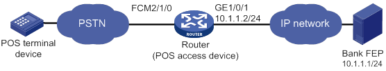
POS dial-up terminal and TCP application configuration example (using an FCM interface)
Network requirements
As shown in Figure 7, The POS terminal dials up to the FCM interface of the POS access device. The POS access device is connected to the FEP through Ethernet.
The POS access service has been enabled on the FEP. The listening port number is 2000.
Configure POS access on the POS access device and configure FCM interface parameters as needed, so the dialup POS terminal can access the FEP.
Configuration procedure
1. Configure interface GigabitEthernet 1/0/1.
[Sysname] interface gigabitethernet 1/0/1
[Sysname-GigabitEthernet1/0/1] ip address 10.1.1.2 255.255.255.0
[Sysname-GigabitEthernet1/0/1] quit
2. Enable POS access service.
<Sysname> system-view
[Sysname] posa server enable
3. Configure the POS application template:
# Configure POS application template 1 in TCP mode.
[Sysname] posa app 1 type tcp
# Specify the IP address and port number of the FEP as 10.1.1.1 and 2000.
[Sysname-posa-app1] ip 10.1.1.1 port 2000
[Sysname-posa-app1] quit
4. Configure the POS terminal template: configure FCM 2/1/0 as the access interface of terminal template 1.
[Sysname] interface fcm 2/1/0
[Sysname–Fcm12/1/0] posa bind terminal 1
5. Configure the FCM negotiation parameters:
# Set the modem negotiation scramble-binary1 time to 200 milliseconds.
[Sysname–Fcm2/1/0] negotiation scramble-binary1 200
# Set the modem negotiation unscramble-binary1 time to 900 milliseconds.
[Sysname–Fcm2/1/0] negotiation unscramble-binary1 900
# Set the modem negotiation silence time to 100 milliseconds.
[Sysname–Fcm2/1/0] negotiation silence 100
# Set the hook off delay time to 2000 milliseconds.
[Sysname–Fcm2/1/0] negotiation hookoff 2000
# Set the no-carrier-detect retry number to 20.
[Sysname–Fcm2/1/0] negotiation no-carrier-detect retry 20
# Set the modem negotiation answer-tone threshold to -41 dBm.
[Sysname–Fcm2/1/0] threshold answer-tone 41
# Set the RLSD turn-off threshold for modem negotiation to -74 dBm.
[Sysname–Fcm2/1/0] threshold rlsdoff 74
# Set the RLSD turn-on threshold for modem negotiation to -73 dBm.
[Sysname–Fcm2/1/0] threshold rlsdon 73
# Set the modem negotiation transmission power threshold to -40 dBm.
[Sysname–Fcm2/1/0] threshold txpower 40
6. Configure a default POS application mapping entry that maps all packets to POS application template 1.
[Sysname] posa map default app 1
You can configure more POS application mapping entries based on the originator and/or destination addresses in the TPDU header as needed.
Verifying the configuration
The POS terminal device sends a POS request packet. The POS access device processes the packet and forwards it to the bank FEP. The FEP receives the request packet and responds with a reply packet. The POS terminal device receives the reply packet.
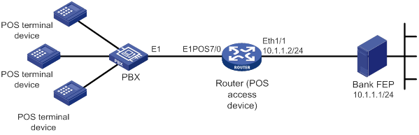
POS dial-up terminal and TCP application configuration example (using an E1POS interface and the PRI protocol)
Network requirements
As shown in Figure 8, POS terminals connect to a PBX through telephone lines and access the router through dial up. The PBX uses an E1 line to connect to the E1POS CE1/PRI interface on the router. The PBX and the router use PRI signaling to exchange messages. The CE1/PRI interface is channelized into FCM subinterfaces. The router connects to the FEP through an Ethernet interface.
Configure POS terminal access on the router so the POS terminals can access the FEP.
Configuration procedure
1. Configure the PRI protocol on E1POS interface E1 7/0.
<Sysname> system-view
[Sysname] controller e1 7/0
[Sysname-E1 7/0] pri-set timeslot-list 1-31
[Sysname-E1 7/0] quit
2. Configure POS terminal access:
# Enable the POS access service.
[Sysname] posa server enable
# Configure the IP address of the Ethernet interface.
[Sysname] interface ethernet 1/1
[Sysname-Ethernet1/1] ip address 10.1.1.2 255.255.255.0
[Sysname-Ethernet1/1] quit
# Configure POS application template 1 in TCP mode.
[Sysname] posa app 1 type tcp
# Set the FEP IP address to 10.1.1.1 and port number to 2000 for application template 1.
[Sysname-posa-app1] ip 10.1.1.1 port 2000
[Sysname-posa-app1] quit
# Configure the FCM subinterfaces on FCM 7/0:15 as POS access interfaces. Bind the interfaces to POS terminal templates starting from POS terminal template 1. Configure the POS terminal templates to operate in transparent mode and configure all to use POS application template 1 to transfer packets to the FEP.
[Sysname] interface fcm 7/0:15
[Sysname-Fcm7/0:15] posa bind terminal first-terminal-id 1 app-list 1:30
[Sysname–Fcm7/0:15] quit
Verifying the configuration
The POS terminal device sends a POS request packet. The POS access device processes the packet and forwards it to the bank FEP. The FEP receives the request packet and responds with a reply packet. The POS terminal device receives the reply packet.
POS flow terminal and flow application configuration example
Network requirements
As shown in Figure 9, a POS terminal is connected to the router through a serial port. The router is connected to COM2 of the FEP through a serial port.
The POS access service has been enabled on the FEP. The FEP uses COM2 to transmit data. The POS terminal packets are destined for 01f1.
Configure POS access on the router so the POS terminal can access the FEP.
Configuration procedure
1. Enable POS access service.
<Sysname> system-view
[Sysname] posa server enable
2. Configure the POS application template:
# Configure the application template 1 in flow mode.
[Sysname] posa app 1 type flow
[Sysname-posa-app1] quit
# Bind Async 2/2/1 to application template 1.
[Sysname] interface async 2/2/1
[Sysname-Async2/2/1] async-mode flow
[Sysname-Async2/2/1] posa bind app 1
[Sysname-Async2/2/1] quit
3. Configure the POS terminal template: bind Async 2/2/0 to POS terminal template 1.
[Sysname] interface async 2/2/0
[Sysname–Async2/2/0] async-mode flow
[Sysname–Async2/2/0] posa bind terminal 1
[Sysname–Async2/2/0] quit
4. Configure a POS application mapping entry to map packets destined for 01f1 to POS application template 1.
[Sysname] posa map destination 01f1 app 1
Verifying the configuration
The POS terminal device sends a POS request packet. The router processes the packet and forwards it to the bank FEP. The FEP receives the request packet and responds with a reply packet. The POS terminal device receives the reply packet.
POS TCP terminal and TCP application configuration example
Network requirements
As shown in Figure 10, a POS terminal is connected to the POS access device through an Ethernet interface. The POS access device is connected to the FEP through an Ethernet interface. The POS access service has been enabled on the FEP. The listening port number is 2000.
Configure POS access on the POS access device so the POS terminal can access the FEP.
Configuration procedure
1. Enable POS access service.
<Sysname> system-view
[Sysname] posa server enable
2. Configure the POS application template:
# Configure application template 1 in TCP mode.
[Sysname] posa app 1 type tcp
# Specify the IP address and port number of the FEP as 2.2.2.1 and 2000.
[Sysname-posa-app1] ip 2.2.2.1 port 2000
[Sysname-posa-app1] quit
3. Configure POS terminal template 1: specify the TCP access mode and configure its listening port number as 3000.
[Sysname] posa terminal 1 type tcp listen-port 3000
4. Configure a default POS application mapping entry to map all packets to application template 1.
[Sysname] posa map default app 1
Verifying the configuration
The POS terminal device sends a POS request packet. The router processes the packet and forwards it to the bank FEP. The FEP receives the request packet and responds with a reply packet. The POS terminal device receives the reply packet.
POS SSL-based TCP terminal and TCP application configuration example
Network requirements
As shown in Figure 11, a POS terminal is connected to the POS access device through an Ethernet interface. The POS access device is connected to the FEP through an Ethernet interface. The POS access device and the POS terminal use SSL-based TCP connections for communication. The POS access service has been enabled on the FEP. The listening port number is 2000.
Configure POS access on the POS access device so the POS terminal can access the FEP.
Configuration procedure
1. Enable POS access service.
<Sysname> system-view
[Sysname] posa server enable
2. Configure the POS application template:
# Configure application template 1 in TCP mode.
[Sysname] posa app 1 type tcp
# Specify the IP address and port number of the FEP as 2.2.2.1 and 2000.
[Sysname-posa-app1] ip 2.2.2.1 port 2000
[Sysname-posa-app1] quit
3. Configure the POS terminal template:
# Create TCP access POS terminal template 1, set the listening port number to 3000, and use SSL-based TCP connections to communicate with the POS terminal.
[Sysname] posa terminal 1 type tcp listen-port 3000 ssl
#Specify SSL server policy serverpolicy for TCP-based POS terminal templates.
[Sysname] posa terminal ssl-server-policy serverpolicy
4. Configure a default POS application mapping entry to map all packets to application template 1.
[Sysname] posa map default app 1
5. Configure an SSL server policy. For more information about configuring an SSL server policy, see Security Configuration Guide.
Verifying the configuration
The POS terminal device sends a POS request packet. The router processes the packet and forwards it to the bank FEP. The FEP receives the request packet and responds with a reply packet. The POS terminal device receives the reply packet.
POS access devices cascade mode configuration example
Network requirements
As shown in Figure 12, POS1 is connected to Router A through dial-up. POS2 is connected to Router A through a serial port. Router A is connected to Router B through Ethernet. Router B is connected to the FEP through Ethernet.
On the FEP, the POS access service has been enabled and the listening port number is 2000.
Configure POS access on the routers so the POS terminals can access the FEP. Use only one TCP connection between the routers for all POS terminals.
Configuration procedure
1. Configure Router A:
# Enable the POS access server.
<RouterA> system-view
[RouterA] posa server enable
# Configure the application template 1 in TCP mode.
[RouterA] posa app 1 type tcp
# Specify the IP address and port number for POS application template 1 as 10.1.3.1 and 3200.
[RouterA-posa-app1] ip 10.1.3.1 port 3200
# Configure the TCP connection mode for application template 1 as permanent. Router A will establish only one TCP connection with Router B for all transactions of POS terminals.
[RouterA-posa-app1] mode permanent
[RouterA-posa-app1] quit
# Bind FCM 2/1/0 to terminal template 1.
[RouterA] interface fcm 2/1/0
[RouterA–Fcm2/1/0] posa bind terminal 1
[RouterA–Fcm2/1/0] quit
# Bind Async 2/2/0 to terminal template 2.
[RouterA] interface async 2/2/0
[RouterA–Async2/2/0] async-mode flow
[RouterA–Async2/2/0] posa bind terminal 2
[RouterA–Async2/2/0] quit
# Configure a default application mapping entry to map all packets to application template 1.
[RouterA] posa map default app 1
2. Configure Router B:
# Enable the POS access service.
<RouterB> system-view
[RouterB] posa server enable
# Configure application template 1 in TCP mode.
[RouterB] posa app 1 type tcp
# Specify the IP address and port number of the corresponding FEP as 10.1.1.1 and 2000.
[RouterB-posa-app1] ip 10.1.1.1 port 2000
[RouterB-posa-app1] quit
# Configure terminal template 1 in TCP mode, and configure its listening port number as 3200.
[RouterB] posa terminal 1 type tcp listen-port 3200
# Configure a default application mapping entry to map all packets to application template 1.
[RouterB] posa map default app 1
Verifying the configuration
A POS terminal device sends a POS request packet. The Router A and Router B process the packet and forward it to the bank FEP. The FEP receives the request packet and responds with a reply packet. The POS terminal device receives the reply packet.
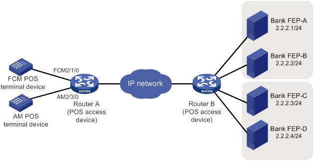
Backup FEP configuration example (nontransparent mode)
Network requirements
Router A provides POS access service for the POS terminals. FEP-A is the primary FEP and FEP-B is the backup FEP for POS 1 and POS 2. FEP-B is the primary FEP and FEP-A is the backup FEP for POS 2 and POS 4.
FEPs have POS access enabled and use the listening port 2000.
Figure 13 Network diagram
Configuration procedure
1. Enable the POS access service.
<RouterA> system-view
[RouterA] posa server enable
2. Configure application template 1:
# Configure application template 1 in TCP mode.
[RouterA] posa app 1 type tcp
# Specify FEP-A with IP address 9.9.9.1 and port number 2000 for application template 1.
[RouterA-posa-app1] ip 9.9.9.1 port 2000
# Enable the handshaking service for application template 1. Configure the handshaking interval to as minutes.
[RouterA-posa-app1] hello enable
[RouterA-posa-app1] timer hello 10
# Specify application template 2 as the backup application template.
[RouterA-posa-app1] backup app 2
# Set the quiet timer for POS application template 1 to 10 minutes.
[RouterA-posa-app1] timer quiet 10
[RouterA-posa-app1] quit
3. Configure POS application template 2:
# Configure application template 2 in TCP mode.
[RouterA] posa app 2 type tcp
# Specify FEP-B with IP address 9.9.9.2 and port number 2000 for POS application 2.
[RouterA-posa-app2] ip 9.9.9.2 port 2000
# Enable the handshaking service for application template 2. Configure the handshaking interval as 10 minutes.
[RouterA-posa-app2] hello enable
[Sysname-posa-app2] timer hello 10
# Specify application template 1 as the backup application template.
[RouterA-posa-app2] backup app 1
# Set the quiet timer for POS application template 2 to 10 minutes.
[RouterA-posa-app2] timer quiet 10
[RouterA-posa-app2] quit
4. Configure the POS terminal templates:
The POS terminals configuration varies with access modes. See the previous configuration examples.
5. Configure POS application mapping entries:
# Map packets sourced from POS 1 and POS 2 to POS application template 1.
[RouterA] posa map source 1111 app 1
[RouterA] posa map source 2222 app 1
# Map packets sourced from POS 3 and POS 4 to POS application template 2.
[RouterA] posa map source 3333 app 2
[RouterA] posa map source 4444 app 2
Verifying the configuration
Follow these steps to verify the backup FEP function:
1. Send a POS packet from the POS terminal when FEP-A is reachable.
Router A forwards the packet to FEP-A. FEP-A receives the packet and responds with a reply packet. The POS terminal device receives the reply packet successfully.
2. Disconnect FEP-A from the network, and then send a POS packet from the POS terminal.
Router A forwards the packet to FEP-B. FEP-B receives the packet and responds with a reply packet. The POS terminal device receives the reply packet successfully.
Backup FEP configuration example (transparent mode)
Network requirements
In transparent mode, a pair of primary and backup FEPs can provide service for only one POS terminal.
As shown in Figure 14, FEP-A (primary FEP) and FEP-B (backup FEP) provide service for the FCM POS terminal. If FEP-A is unreachable, FEP-B is used. FEP-C (primary FEP) and FEP-D (backup FEP) provide service for the AM POS terminal. If FEP-C is unreachable, FEP-D is used.
The FEPs have POS access enabled and use the listening port 2000.
Configuration procedure
1. Enable the POS access service.
<RouterA> system-view
[RouterA] posa server enable
2. Configure POS application template 1:
# Configure application template 1 in TCP mode.
[RouterA] posa app 1 type tcp
# Specify FEP-A with IP address 2.2.2.1 and port number 2000 for application template 1.
[RouterA-posa-app1] ip 2.2.2.1 port 2000
# Specify application template 2 as the backup application template.
[RouterA-posa-app1] backup app 2
# Set the quiet timer for POS application template 1 to 10 minutes.
[RouterA-posa-app1] timer quiet 10
[RouterA-posa-app1] quit
3. Configure POS application template 2:
# Configure application template 2 in TCP mode.
[RouterA] posa app 2 type tcp
# Specify FEP-B with IP address 2.2.2.2 and port number 2000 for POS application template 2.
[RouterA-posa-app2] ip 2.2.2.2 port 2000
[RouterA-posa-app2] quit
4. Configure POS application template 3:
# Configure application template 3 in TCP mode.
[RouterA] posa app 3 type tcp
# Specify FEP-C with IP address 2.2.2.3 and port number 2000 for POS application 3.
[RouterA-posa-app3] ip 2.2.2.3 port 2000
# Specify application template 4 as the backup application template.
[RouterA-posa-app3] backup app 4
# Set the quiet timer for POS application template 3 to 10 minutes.
[RouterA-posa-app3] timer quiet 10
[RouterA-posa-app3] quit
5. Configure POS application template 4:
# Configure application template 4 in TCP mode.
[RouterA] posa app 4 type tcp
# Specify FEP-D with IP address 2.2.2.4 and port number 2000 for POS application 4.
[RouterA-posa-app4] ip 2.2.2.4 port 2000
[RouterA-posa-app4] quit
6. Configure the AM POS terminal template:
# Configure interface AM 2/3/0 as the access interface of terminal template 11. Specify terminal template 11 to use POS application template 3 to transparently transport packets of the terminal.
[RouterA] interface analogmodem 2/3/0
[RouterA-Analogmodem2/3/0] posa bind terminal 11 app 3
[RouterA-Analogmodem2/3/0] quit
7. Configure the FCM POS terminal template:
# Configure interface FCM 2/1/0 as the access interface of terminal template 12. Specify terminal template 12 to use POS application template 1 to transparently transport packets of the terminal.
[RouterA] interface fcm 2/1/0
[RouterA-Fcm2/1/0] posa bind terminal 12 app 1
[RouterA-Fcm2/1/0] quit
Verifying the configuration
Follow these steps to verify the backup FEP function for the POS terminal that uses FCM 2/1/0:
1. Send a POS packet from the POS terminal when FEP-A is reachable.
Router A forwards the packet to FEP-A. FEP-A receives the packet and responds with a reply packet. The POS terminal device receives the reply packet successfully.
2. Disconnect FEP-A from the network, and then send a POS packet from the POS terminal.
Router A forwards the packet to FEP-B. FEP-B receives the packet and responds with a reply packet. The POS terminal device receives the reply packet successfully.
Follow these steps to verify the backup FEP function for the POS terminal that uses AM 2/3/0:
3. Send a POS packet from the POS terminal when FEP-C is reachable.
Router A forwards the packet to FEP-C. FEP-C receives the packet and responds with a reply packet. The POS terminal device receives the reply packet successfully.
4. Disconnect FEP-C from the network, and then send a POS packet from the POS terminal.
Router A forwards the packet to FEP-D. FEP-D receives the packet and responds with a reply packet. The POS terminal device receives the reply packet successfully.
Configuring RTC terminal access
Overview
Terminal access enables a terminal to use a serial interface to access another terminal through routers. Remote terminal connection (RTC) terminal access is a typical application of terminal access. RTC terminal access interconnects a local terminal and a remote terminal through routers for data monitoring and data sharing.
Basic concepts
The following types of network devices are used in RTC terminal access:
· Terminal—A terminal refers to a character device that is generally connected to a router through a serial interface cable.
· Initiator—An initiator refers to a router that sends a connection request and acts as the RTC client of the connection.
· Receiver—A receiver refers to a router that responds to a connection request and acts as the RTC server of the connection.
· Relay server—A relay server provides functions similar to a receiver, except that the relay server is not directly connected to terminals. Instead, the relay server is connected to multiple initiators and manages them in different forwarding groups according to the listening port numbers. Data received from an initiator is forwarded to other initiators in the same group.
|
|
NOTE: In an actual network, the receiver and the relay server are not both deployed. |
After a connection is established between an initiator and a receiver, the initiator and receiver can transparently transmit data from the local terminal to the remote terminal over the connection. The transmission is transparent in that no manual or extra operation is required.
Connections between an initiator and a receiver can use either TCP or UDP.
Typical applications of RTC terminal access
RTC terminal access has the following purposes:
· Enabling a monitoring device to manage and monitor remote terminals.
· Sharing data among multiple terminals such as radar devices.
· Collecting data from remote terminals.
· Synchronizing signal data on a broadcast communication network.
RTC terminal access supports synchronous mode and asynchronous mode.
· Asynchronous mode—In asynchronous mode, an initiator and a receiver support only TCP connections between them, including the following types:
? TCP one-to-one transparent transmission between one RTC client and one RTC server.
? TCP many-to-one transparent transmission between multiple RTC clients and one relay server.
· Synchronous mode—In synchronous mode, an initiator and a receiver support TCP or UDP connections, including the following types:
? TCP/UDP one-to-one transparent transmission between one RTC client and one RTC server.
? TCP many-to-one transparent transmission between multiple RTC clients and one relay server.
? UDP one-to-many transparent transmission between one RTC server and multiple RTC clients.
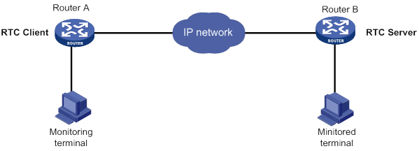
TCP or UDP one-to-one transparent transmission
Figure 15 shows a typical network diagram for the one-to-one transparent transmission. Router A initiates a monitoring request to access the data on the monitored terminal. Router B receives the monitoring request and sends the data of the monitored terminal to Router A. TCP RTC transparent transmission can ensure high reliability of the data transmitted, but it has a certain forwarding delay. Because voice service does not require high reliability, the UDP RTC transparent transmission is mainly applied to voice transmission.
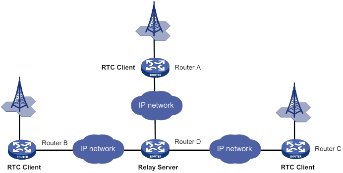
TCP many-to-one transparent transmission
Some terminal devices, such as radars, need to share data with one another. RTC terminal access provides many-to-one relay forwarding based on TCP. Routers connecting these terminals are connected to one relay server, which forwards data received from a router to other routers in the same group.
Figure 16 Network diagram
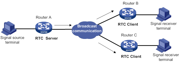
UDP one-to-many transparent transmission
UDP one-to-many transparent transmission is mainly applied to signal synchronization for unidirectional broadcast communication links. Figure 17 shows a typical network diagram for this type of transmission.
The UDP one-to-many transparent transmission procedure takes the following steps:
1. The signal source terminal sends data.
2. The RTC server sends the data to all RTC clients.
3. The RTC clients forward the data to the signal receiver terminals and do not respond to the RTC server.
RTC terminal access feature list
The following table lists the features supported by RTC terminal access. "All" in this table means that the feature is supported by all RTC access types, which include the following:
· TCP_11_Client (RTC TCP one-to-one client).
· TCP_11_Server (RTC TCP one-to-one server).
· TCP_N1_Server (relay server).
· UDP_11_Client (RTC UDP one-to-one client).
· UDP_11_Server (RTC UDP one-to-one server).
· UDP_1N_Server (RTC UDP one-to-many server).
|
Feature |
Supported by |
Description |
|
TCP_11_Client |
N/A |
|
|
TCP_11_Client |
N/A |
|
|
TCP_11_Client, TCP_11_Server, |
N/A |
|
|
TCP_11_Client |
N/A |
|
|
TCP_11_Client, TCP_11_Server, |
N/A |
|
|
TCP_11_Client |
N/A |
|
|
TTCP_11_Client, TCP_11_Server, TCP_N1_Server |
N/A |
|
|
TTCP_11_Client, TCP_11_Server, TCP_N1_Server |
N/A |
|
|
TCP_11_Client, TCP_11_Server, TCP_11_Server |
N/A |
|
|
TCP_11_Client, TCP_11_Server, UDP_11_Client, UDP_11_Server |
N/A |
|
|
TCP_11_Client, TCP_11_Server, TCP_N1_Server |
N/A |
|
|
Access types supporting synchronous terminals |
N/A |
|
|
All |
N/A |
|
|
Information debugging |
All |
For more information, see Terminal Access Debugging Command Manual. |
RTC terminal access features
Source address binding
This function specifies the source IP address of the TCP connection initiated from the router. You can use this function for the following purposes:
· For stable status—Use the IP address of a stable interface, for example, a loopback interface or a dialer interface, as the TCP source IP address.
· For security or some other reason—Specify a TCP source IP address to hide the IP address of the physical interface that is used in the upstream TCP connection.
Make sure the receiver and the interface whose IP address is used as the TCP source address can reach each other.
Fast VTY service switching
In RTC terminal access, each terminal is logically divided into eight virtual type terminals (VTYs). Each VTY can be configured to correspond to a service, which is also known as an application. On a terminal, you can press the hotkey to bring up the VTY switching menu and select a VTY.
Connection idle timeout
The initiator and receiver are automatically disconnected from each other when the following conditions are met:
· A connection idle timeout has been set.
· No data is transmitted between the initiator and receiver during the connection idle timeout period.
Automatic link establishment
You can enable this function and configure the automatic link establishment time in terminal template view. When the terminal is successfully connected to the initiator, the initiator automatically establishes a TCP connection to the receiver after the specified auto establishment time.
If this function is disabled, the initiator establishes a TCP connection to the receiver only when you enter a character on the terminal.
Automatic link teardown
You can enable this function and configure the automatic teardown time for the terminal in terminal template view. When the terminal and the initiator are disconnected from each other, the terminal enters down state. After the automatic teardown time, the initiator automatically tears down the TCP connection to the receiver. The TCP connection always remains active if the automatic link teardown function is disabled.
Terminal reset
When a terminal fails to communicate with the receiver, you can re-establish communication by pressing the terminal reset hotkey on the terminal. The initiator will disconnect and then re-establish the TCP connection with the receiver.
TCP parameter configuration
TCP buffers store the data exchanged between the initiator and receiver. You can set the following TCP connection parameters:
· Receive buffer size.
· Send buffer size.
· Non-delay attribute.
· Keepalive interval and number.
Terminal buffer parameter configuration
· Whether to clear the receive buffer before receiving data.
· Receive buffer size.
· Send buffer threshold.
· Maximum size of data to be sent to the terminal at one time.
RTC terminal authentication
Terminal access VPNs
TCP NODELAY
In TCP many-to-one or TCP one-to-one transparent transmission mode, the RTC client and the RTC server use the Nagle algorithm to prevent network congestion caused by a large number of TCP packets. For more information, see RFC 896.
The Nagle algorithm also causes time delay during TCP packet transmission, especially for interactive applications. The RTC client and the RTC server allow you to disable the Nagle algorithm by setting the TCP_NODELAY option.
Link backup
One terminal or two terminals can connect to two synchronous serial interfaces of a router through two links. To configure backup between the two links, you can configure the two synchronous serial interfaces as primary and backup interfaces for the terminal access. When the primary interface is operating correctly, the router and the terminal communicate through the primary interface. When the primary interface fails or when the number of cyclic redundancy check errors on the primary interface reaches the upper threshold, the backup interface takes over. The primary interface takes over again when it recovers from a failure condition.
Compatibility mode support
RTC terminal access supports the following data transmission mode: characteristic mode and compatibility mode. The RTC server and the RTC client must operate in the same data transmission mode.
Devices running Comware 3 or Comware 5 can operate only in characteristic mode or compatibility mode. The mode is automatically set and is not user configurable.
Devices running Comware 7 can operate in either characteristic or compatibility mode, depending on your configuration. The default mode is characteristic mode.
RTC terminal access specifications
RTC terminal access initiator specifications
|
Item |
Specification |
|
Maximum number of TTYs |
255 This number is subject to the number of router interfaces available for terminal access. |
|
Maximum number of VTYs supported by each TTY |
8 |
|
Interface types supported by RTC terminal access |
Asynchronous serial interface Synchronous/asynchronous serial interface |
|
Terminal emulation type |
VT100 and VT200 |
|
Terminal baud rate |
300 bps to 115200 bps |
|
Access types supporting asynchronous terminals |
TCP_11_Client |
|
Access types supporting synchronous terminals |
UDP_11_Client |
RTC terminal access receiver specifications
|
Item |
Specification |
|
Maximum number of TTYs |
255 This number is subject to the number of router interfaces available for terminal access. |
|
Maximum number of VTYs supported by each TTY |
8 |
|
Maximum number of remote terminals supported by UDP_1N_Server |
10 |
|
Access types supporting asynchronous terminals |
TCP_11_Server, TCP_N1_Server |
|
Access types supporting synchronous terminals |
UDP_11_Server, UDP_1N_Server, TCP_N1_Server |
Relay server specifications
|
Item |
Specification |
|
Maximum number of forwarding groups supported by a TCP_N1_Server |
64 |
|
Maximum number of TCP_11_Clients supported by each forwarding group of a TCP_N1_Server |
10 |
Feature and hardware compatibility
|
Hardware |
RTC terminal access compatibility |
|
MSR810/810-W/810-W-DB/810-LM/810-W-LM/810-10-PoE/810-LM-HK/810-W-LM-HK/810-LMS/810-LUS |
No |
|
MSR2600-6-X1/2600-10-X1 |
No |
|
MSR 2630 |
Yes |
|
MSR3600-28/3600-51 |
Yes |
|
MSR3600-28-SI/3600-51-SI |
No |
|
MSR3610-X1/3610-X1-DP/3610-X1-DC/3610-X1-DP-DC |
Yes |
|
MSR 3610/3620/3620-DP/3640/3660 |
Yes |
|
MSR5620/5660/5680 |
Yes |
|
Hardware |
RTC terminal access compatibility |
|
MSR810-LM-GL |
No |
|
MSR810-W-LM-GL |
No |
|
MSR830-6EI-GL |
No |
|
MSR830-10EI-GL |
No |
|
MSR830-6HI-GL |
No |
|
MSR830-10HI-GL |
No |
|
MSR2600-6-X1-GL |
No |
|
MSR3600-28-SI-GL |
No |
--
RTC terminal access configuration task list
To configure RTC terminal access, configure the initiator and the receiver as required.
The RTC terminal access configuration commands can be executed in user view, system view, terminal template view, or interface view. Most of the important settings are configured in terminal templates on a router. The templates are applied to corresponding interfaces (such as an asynchronous serial interface). The router then creates TTYs and VTYs according to the template configurations. Only one template can be applied to an interface.
If you modify a template that has been applied to an interface, use the update changed-config command to update the configuration.
To configure RTC terminal access, complete the following tasks:
Configuring the asynchronous TCP RTC one-to-one initiator (TCP_11_Client)
The initiator is a TCP_11_Client connected to the monitoring device. The receiver is a TCP_11_Server connected to the monitored device. The TCP_11_Client can initiate a connection request to the TCP_11_Server at any time to obtain the data of the monitored device.
Basic TCP_11_Client configuration
|
Step |
Command |
Remarks |
|
1. Enter system view. |
system-view |
N/A |
|
2. Enable terminal access on the router. |
rta server enable |
By default, terminal access on the router is disabled. |
|
3. Create a terminal template and enter terminal template view. |
rta template template-name |
N/A |
|
4. Create a TCP RTC client VTY. |
vty vty-number rtc-client remote ip-address port-number [ source source-ip ] |
By default, no TCP RTC client VTYs exist. The port number configured for the RTC client VTY must be the same as the listening port number configured on the RTC server. The source IP address, if configured, has priority over the global TCP source address for the terminal. After this configuration, the template cannot be configured with any RTC server VTYs. |
|
5. Return to system view. |
quit |
N/A |
|
6. Enter TTY user line view. |
line { first-num1 [ last-num1 ] | tty first-num2 [ last-num2 ] } |
For more information about the line command, see Fundamentals Command Reference. |
|
7. Disable the terminal service for the current user line. |
undo shell |
By default, the terminal service is enabled on all user lines. Disable the terminal service for the current user line before applying the terminal template to an interface. For more information about the shell command, see Fundamentals Command Reference. |
|
8. Enable software flow control of data on the current user interface. |
flow-control software |
By default, the router performs hardware flow control of data on the current user interface. For more information about the flow-control command, see Fundamentals Command Reference. |
|
9. Return to system view. |
quit |
N/A |
|
10. Enter interface view. |
interface interface-type interface-number |
The interface type must be supported by RTC terminal access. Synchronous and asynchronous interfaces are supported. |
|
11. Configure the operating mode or protocol type for the interface. |
·
For an asynchronous serial interface,
specify the operating mode as flow: ·
For a synchronous serial interface,
specify the protocol type as STLP: |
Use either command according to the interface type. By default, an asynchronous serial interface operates in the protocol mode, and a synchronous serial interface operates in the PPP protocol mode. For more information about the async-mode command, see Interface Command Reference. |
|
12. Apply the template to the interface. |
rta terminal template-name terminal-number |
By default, no template is applied to the interface. |
|
13. Return to system view. |
quit |
N/A |
Advanced TCP_11_Client configuration
|
Step |
Command |
Remarks |
|
1. Enter system view. |
system-view |
N/A |
|
2. Configure the global source IP address for TCP connections. |
rta source-ip ip-address |
By default, no global source IP address for TCP connections is configured. A source IP address configured in terminal template view has priority over the global TCP source address for the terminal. |
|
3. Enter terminal template view. |
rta template template-name |
N/A |
|
4. Configure the automatic link teardown time. |
auto-close time |
By default, the automatic link teardown time is 0 seconds, which indicates that no automatic link teardown will be performed. |
|
5. Configure the automatic link establishment time. |
auto-link time |
By default, the automatic link establishment time is 0 seconds, which indicates that no automatic link establishment will be performed. |
|
6. Bind a VPN instance to the template. |
bind vpn-instance vpn-instance-name |
By default, the template is not bound with any VPN instance. This command is used when the RTC client is also acting as an MPLS PE router. After you apply a terminal template associated with a VPN instance to an asynchronous serial interface, the terminal connected to the asynchronous serial interface is bound to that VPN instance. Then, the RTC client can receive terminal access packets from multiple VPNs through the asynchronous serial interfaces and initiate connection requests. |
|
7. Configure the router to not clear the terminal buffer after a TCP connection is established. |
driverbuf save |
By default, the router clears the terminal receive buffer after a TCP connection is established. |
|
8. Configure the terminal receive buffer size. |
driverbuf size size |
By default, the terminal receive buffer size is 8 KB. |
|
9. Configure the TCP connection idle timeout time. |
idle-timeout seconds |
By default, the TCP connection idle timeout time is 0 seconds, which indicates that the connection never times out. |
|
10. Set the terminal reset hotkey. |
resetkey ascii-code&<1-3> |
By default, no terminal reset hotkey is configured. |
|
11. Configure the maximum size of data sent to a terminal at one time. |
sendbuf bufsize size |
By default, the maximum size of data sent to a terminal at one time is 500 bytes. |
|
12. Configure the terminal send buffer threshold. |
sendbuf threshold value |
By default, no terminal send buffer threshold is configured. |
|
13. Configure TCP parameters. |
tcp { recvbuf-size recvsize | sendbuf-size sendsize | nodelay | keepalive time count } |
By default: · The receive buffer size is 2048 bytes. · The send buffer size is 2048 bytes. · Delay is enabled. · The keepalive interval is 50 seconds. · The keepalive number is 3. This command takes effect only after a TCP connection is re-established. |
|
14. Configure the password for VTY authentication. |
vty vty-number password { simple | cipher } string |
By default, no password for VTY authentication is configured. To implement terminal access authentication, you must configure terminal access authentication on both the RTC server and the RTC client. The authentication passwords must be identical for the authentication to succeed. |
|
15. Configure the VTY switching hotkey. |
vty vty-number hotkey ascii-code&<1-3> |
By default, no VTY switching hotkey is configured. The ASCII value of the hotkey must be different from the ASCII value of any other hotkey configured on the device. Otherwise, hotkey conflicts will occur. For example, the hotkey value cannot be 17 or 19 because these two values are used for flow control. In addition, using the hotkey may not get a fast response when the terminal display is busy. |
|
16. Update the configuration. |
update changed-config |
If you modify a terminal template that has been applied to an interface, use this command to apply the most recent configuration. Executing this command will disconnect connections and re-establish connections. Make sure critical services are not affected. |
Configuring the asynchronous TCP RTC one-to-one receiver (TCP_11_Server)
Basic TCP_11_Server configuration
|
Step |
Command |
Remarks |
|
1. Enter system view. |
system-view |
N/A |
|
2. Enable terminal access on the router. |
rta server enable |
By default, terminal access on the router is disabled. |
|
3. Configure the listening port. |
rta rtc-server listen-port port-number |
By default, no listening port is configured. This listening port number must be the same as the port number configured on the RTC client. |
|
4. Create a terminal template and enter terminal template view. |
rta template template-name |
N/A |
|
5. Create a TCP RTC server VTY. |
vty vty-number rtc-server remote ip-address terminal-number |
By default, no RTC server VTYs exist. After this configuration, the template cannot be configured with any RTC client VTYs. The terminal-number argument of the vty rtc-server remote command configured on the RTC server must be the same as the terminal-number argument of the rta terminal command configured on the RTC client. Otherwise, no TCP connection can be established. Each VTY of the RTC server must correspond to a different RTC client. |
|
6. Return to system view. |
quit |
N/A |
|
7. Enter TTY user line view. |
line { first-num1 [ last-num1 ] | tty first-num2 [ last-num2 ] } |
For more information about the line command, see Fundamentals Command Reference. |
|
8. Disable the terminal service for the current user line. |
undo shell |
By default, the terminal service is enabled on all user lines. Disable the terminal service for the current user line before applying the terminal template to an interface. For more information about the shell command, see Fundamentals Command Reference. |
|
9. Enable software flow control of data on the current user interface. |
flow-control software |
By default, the router performs hardware flow control of data on the current user interface. For more information about the flow-control command, see Fundamentals Command Reference. |
|
10. Return to system view. |
quit |
N/A |
|
11. Enter interface view. |
interface interface-type interface-number |
The interface type must be supported by RTC terminal access. Synchronous and asynchronous interfaces are supported. |
|
12. Configure the operating mode or protocol type for the interface. |
·
For an asynchronous serial interface,
specify the operating mode as flow: ·
For a synchronous serial interface,
specify the protocol type as STLP: |
Use either command according to the interface type. By default, an asynchronous serial interface operates in the protocol mode, and a synchronous serial interface operates in the PPP protocol mode. For more information about the async-mode command, see Interface Command Reference. |
|
13. Apply the template to the interface. |
rta terminal template-name terminal-number |
N/A |
Advanced TCP_11_Server configuration
|
Step |
Command |
Remarks |
|
1. Enter system view. |
system-view |
N/A |
|
2. Configure the global source IP address for TCP connections. |
rta source-ip ip-address |
By default, no global source IP address for TCP connections is configured. A source IP address configured in terminal template view takes precedence over the global TCP source address for the corresponding terminal. |
|
3. Enter terminal template view. |
rta template template-name |
N/A |
|
4. Configure the automatic link teardown time. |
auto-close time |
By default, the automatic link teardown time is 0 seconds, which indicates that no automatic link teardown is performed. |
|
5. Bind a VPN instance to the template. |
bind vpn-instance vpn-instance-name |
By default, the template is not bound with any VPN instance. |
|
6. Configure the router to not clear the terminal buffer after a TCP connection is established. |
driverbuf save |
By default, the router clears the terminal receive buffer after a TCP connection is established. |
|
7. Configure the terminal receive buffer size. |
driverbuf size size |
By default, the terminal receive buffer size is 8 KB. |
|
8. Configure the TCP connection idle timeout time. |
idle-timeout seconds |
By default, the TCP connection idle timeout time is 0 seconds, which indicates that the connection never times out. |
|
9. Configure the maximum size of data sent to a terminal at one time. |
sendbuf bufsize size |
By default, the maximum size of data sent to a terminal at one time is 500 bytes. |
|
10. Configure the terminal send buffer threshold. |
sendbuf threshold value |
By default, no terminal send buffer threshold is configured. |
|
11. Configure TCP parameters. |
tcp { recvbuf-size recvsize | sendbuf-size sendsize | nodelay | keepalive time count } |
By default: · The receive buffer size is 2048 bytes. · The send buffer size is 2048 bytes. · Delay is enabled. · The keepalive interval is 50 seconds. · The keepalive number is 3. This command takes effect only after a TCP connection is re-established. |
|
12. Configure the password for VTY authentication. |
vty vty-number password { simple | cipher } string |
By default, no password for VTY authentication is configured. To implement terminal access authentication, you must configure terminal access authentication on both the RTC server and the RTC client, and the authentication passwords must be identical for the authentication to succeed. |
|
13. Update the configuration. |
update changed-config |
If you modify a terminal template that has been applied to an interface, use this command to apply the most recent configuration. Executing this command will disconnect connections and re-establish connections. Make sure critical services are not affected. |
Configuring the TCP RTC many-to-one relay server (TCP_N1_Server)
The initiators are TCP_11_Clients, which are connected to monitoring devices. The receiver is a relay server (TCP_N1_Server) which is not connected to any monitored device.
To configure a TCP_N1_Server:
|
Step |
Command |
Remarks |
|
1. Enter system view. |
system-view |
N/A |
|
2. Enable relay forwarding. |
rta relay enable |
By default, relay forwarding is disabled. |
|
3. Configure a TCP listening port. |
rta relay listen-port port-number |
By default, no TCP is configured. |
|
4. (Optional.) Set the send buffer size and receive buffer size for TCP connections. |
rta relay tcp { recvbuf-size recvbuff-size | sendbuf-size sendbuff-size } |
By default, the send buffer size and the receive buffer size for TCP connections are 2048 bytes. As a best practice, use the default values. An improper send buffer size or receive buffer size affects data forwarding efficiency and might cause system overload. |
|
5. (Optional.) Configure the keepalive attributes for TCP connections between the relay server and a client. |
rta relay tcp keepalive time count |
By default, the keepalive interval is 50 seconds and the keepalive number is 3. If the relay server receives no keepalive reply from a client within three keepalive intervals, it disconnects the client. The TCP keepalive detection configuration takes effect immediately. Do not decrease the keepalive interval if the keepalive number is 1. A shorter keepalive interval might cause the device to disconnect all clients. |
|
6. (Optional.) Set the forward buffer size for each RTC client. |
rta relay buffer-size buffer-size |
By default, the forward buffer size for an RTC client is 8 KB. A larger forward buffer consumes more memory. |
|
7. (Optional.) Enable the TCP_NODELAY function. |
rta relay tcp nodelay |
By default, the TCP_NODELAY function is disabled. |
Configuring the synchronous UDP RTC one-to-one initiator (UDP_11_Client)
The initiator is a UDP_11_Client, which is connected to the monitoring device through a synchronous serial interface. The receiver is a UDP_11_Server, which is connected to the monitored device through a synchronous serial interface. The initiator can establish a UDP connection with the receiver at any time to obtain data.
To configure a UDP_11_Client:
|
Step |
Command |
Remarks |
|
1. Enter system view. |
system-view |
N/A |
|
2. Enable terminal access. |
rta server enable |
By default, terminal access is disabled. |
|
3. Create a terminal template and enter terminal template view. |
rta template template-name |
N/A |
|
4. Create a UDP RTC client VTY. |
vty vty-number rtc-client remote ip-address remote-port remote-port-number udp [ local-port local-port-number ] [ source source-ip-address ] |
By default, no UDP RTC client VTYs exist. After this configuration, you cannot configure VTYs of other types in the template. |
|
5. Return to system view. |
quit |
N/A |
|
6. Enter the view of the primary interface. |
interface interface-type interface-number |
N/A |
|
7. Configure the protocol type of the synchronous serial interface as STLP. |
link-protocol stlp |
By default, a synchronous serial interface operates in the PPP protocol mode. |
|
8. Apply the template to the primary interface. |
rta terminal template-name terminal-number |
N/A |
|
9. Return to system view. |
quit |
N/A |
|
10. (Optional.) Enter the view of the backup interface. |
interface interface-type interface-number |
N/A |
|
11. (Optional.) Configure the protocol type of the synchronous serial interface as STLP. |
link-protocol stlp |
By default, a synchronous serial interface operates in PPP protocol mode. |
|
12. (Optional.) Apply the template to the backup interface. |
rta terminal template-name terminal-number backup |
The template-name and terminal-number arguments of the rta terminal backup command must be the same as those of the rta terminal command. |
Configuring the synchronous UDP RTC one-to-one receiver (UDP_11_Server)
|
Step |
Command |
Remarks |
|
1. Enter system view. |
system-view |
N/A |
|
2. Enable terminal access. |
rta server enable |
N/A |
|
3. Create a terminal template and enter terminal template view. |
rta template template-name |
N/A |
|
4. Create a UDP RTC server VTY. |
vty vty-number rtc-server remote [ ip-address remote-port remote-port-number ] udp local-port local-port-number [ source source-ip-address ] |
By default, no UDP RTC server VTYs exist. After this configuration, you cannot configure VTYs of other types in the template. Each VTY of the RTC server corresponds to a different RTC client. |
|
5. Return to system view. |
quit |
N/A |
|
6. Enter the view of the primary interface |
interface interface-type interface-number |
N/A |
|
7. Configure the protocol type of the synchronous serial interface as STLP. |
link-protocol stlp |
By default, a serial interface operates in PPP protocol mode. |
|
8. Apply the template to the primary interface. |
rta terminal template-name terminal-number |
N/A |
|
9. Return to system view. |
quit |
N/A |
|
10. (Optional.) Enter the view of the backup interface. |
interface interface-type interface-number |
N/A |
|
11. (Optional.) Configure the protocol type of the synchronous serial interface as STLP. |
link-protocol stlp |
By default, a synchronous serial interface operates in PPP protocol mode. |
|
12. (Optional.) Apply the template to the backup interface. |
rta terminal template-name terminal-number backup |
The template-name and terminal-number arguments of the rta terminal backup command must be the same as those of the rta terminal command. |
Configuring the synchronous UDP RTC one-to-many receiver (UDP_1N_Server)
The initiator is a UDP_11_Client, which is connected to the monitoring device through a synchronous serial interface. The receiver is a UDP_1N_Server, which is connected to the monitored device through a synchronous serial interface. An initiator can establish a UDP connection with a receiver at any time to obtain data. Multiple initiators are connected to a receiver, and the receiver sends data from a monitored device to all initiators simultaneously.
To configure a UDP_1N_Server:
|
Step |
Command |
Remarks |
|
1. Enter system view. |
system-view |
N/A |
|
2. Enable terminal access. |
rta server enable |
N/A |
|
3. Create a terminal template and enter terminal template view. |
rta template template-name |
N/A |
|
4. Create a one-to-many UDP RTC server VTY. |
vty vty-number rtc-multipeer [ ip-address ] port-number |
By default, no one-to-many UDP RTC server VTYs exist. After this configuration, you cannot configure VTYs of other types of in the template. |
|
5. Configure the client list. |
rtc-multipeer vty-number remote ip-address port-number |
By default, no client is configured. You must create a UDP_1N_Server VTY before performing this configuration. You can configure up to ten clients for a VTY. |
|
6. Return to system view. |
quit |
N/A |
|
7. Enter the view of the primary interface. |
interface interface-type interface-number |
The interface type must be supported by terminal access. |
|
8. Configure the protocol type of the synchronous serial interface as STLP. |
link-protocol stlp |
By default, a synchronous serial interface operates in PPP protocol mode. |
|
9. Apply the template to the primary interface. |
rta terminal template-name terminal-number |
N/A |
|
10. Quit the view of the primary interface. |
quit |
N/A |
|
11. (Optional.) Enter the view of the backup interface. |
interface interface-type interface-number |
The interface type must be supported by terminal access. |
|
12. (Optional.) Configure the protocol type of the synchronous serial interface as STLP. |
link-protocol stlp |
By default, a synchronous serial interface operates in PPP protocol mode. |
|
13. (Optional.) Apply the template to the backup interface. |
rta terminal template-name terminal-number backup |
The template-name and terminal-number arguments of the rta terminal backup command must be the same as those of the rta terminal command. |
Setting the RTC version
The following matrix shows the feature and hardware compatibility:
|
Hardware |
RTC version setting compatibility |
|
MSR810/810-W/810-W-DB/810-LM/810-W-LM/810-10-PoE/810-LM-HK/810-W-LM-HK/810-LMS/810-LUS |
No |
|
MSR2600-6-X1/2600-10-X1 |
No |
|
MSR 2630 |
Yes |
|
MSR3600-28/3600-51 |
Yes |
|
MSR3600-28-SI/3600-51-SI |
No |
|
MSR3610-X1/3610-X1-DP/3610-X1-DC/3610-X1-DP-DC |
Yes |
|
MSR 3610/3620/3620-DP/3640/3660 |
Yes |
|
MSR5620/5660/5680 |
Yes |
The RTC protocol has the following versions: Version 3 and Version 5. Routers running Comware 3 support only Version 3. Routers running Comware 5 or Comware 7 support both Version 3 and Version 5.
To set the RTC version:
|
Step |
Command |
Remarks |
|
1. Enter system view. |
system-view |
N/A |
|
2. Configure the RTC version. |
rta rtc version { v3 | v5 } |
By default, the router uses Version 5. |
Displaying and maintaining RTC terminal access
Execute displays commands in any view and reset commands in user view.
|
Task |
Command |
|
Display terminal access information. |
display rta { all | statistics | terminal-number { vty-number | brief | detail | statistics } } |
|
Display states of all RTC client connections accepted by a relay server. |
display rta relay status |
|
Display the forwarding statistics of a relay server. |
display rta relay statistics |
|
Clear statistics for a terminal. |
reset rta statistics terminal-number |
|
Clear the packet statistics for clients connected to the relay server. |
reset rta relay statistics |
|
Disconnect client connections from a relay server. |
rta relay disconnect { server-id client-id | all } |
RTC terminal access configuration examples
Asynchronous TCP RTC one-to-one configuration example
Network requirements
As shown in Figure 18, the RTC client and the RTC server are connected to the central terminal device and the remote terminal device, respectively.
Configure the RTC client and the RTC server to enable the central terminal to monitor the remote terminal:
· Set the listening number of the RTC server to 9000.
· Set the terminal number to 1 on both the RTC client and the RTC server.
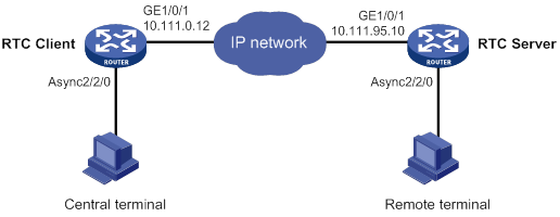
Configuration procedure
1. Configure the RTC server:
# Enable terminal access.
<Sysname> system-view
[Sysname] rta server enable
# Set the listening port of the server.
[Sysname] rta rtc-server listen-port 9000
# Create a terminal template and enter terminal template view.
[Sysname] rta template rtcserver
# Configure the VTY.
[Sysname-rta-template-rtcserver] vty 0 rtc-server remote 10.111.0.12 1
[Sysname-rta-template-rtcserver] vty 0 password simple 123
[Sysname-rta-template-rtcserver] quit
# Apply the template to the interface.
[Sysname] interface async 2/2/0
[Sysname-Async2/2/0] async mode flow
[Sysname-Async2/2/0] rta terminal rtcserver 1
2. Configure the RTC client:
# Enable terminal access.
<Sysname> system-view
[Sysname] rta server enable
# Create a terminal template and enter terminal template view.
[Sysname] rta template rtcclient
# Configure the VTY.
[Sysname-rta-template-rtcclient] vty 0 rtc-client remote 10.111.95.10 9000
[Sysname-rta-template-rtcclient] vty 0 password simple 123
[Sysname-rta-template-rtcclient] quit
# Apply the template to the interface.
[Sysname] interface async 2/2/0
[Sysname-Async2/2/0] async mode flow
[Sysname-Async2/2/0] rta terminal rtcclient 1
Verifying the configuration
# Send an instruction from the central terminal to the remote terminal.
# Check that the remote terminal can receive the instruction, and check that the central terminal can receive the requested data from the remote terminal.
Synchronous TCP RTC one-to-one configuration example
Network requirements
As shown in Figure 19, the RTC client and the RTC server are connected to the central terminal device and the remote terminal device through synchronous serial interface Serial 2/2/0.
Configure the RTC client and the RTC server to enable the central terminal to monitor the remote terminal:
· Set the listening number of the RTC server to 9000.
· Set the terminal number to 1 on both the RTC client and the RTC server.
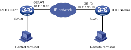
Configuration procedure
1. Configure the RTC server:
# Enable terminal access.
<Sysname> system-view
[Sysname] rta server enable
# Set the listening port of the server.
[Sysname] rta rtc-server listen-port 9000
# Create a terminal template and enter terminal template view.
[Sysname] rta template rtcserver
# Configure the VTY.
[Sysname-rta-template-rtcserver] vty 0 rtc-server remote 10.111.0.12 1
[Sysname-rta-template-rtcserver] vty 0 password simple 123
[Sysname-rta-template-rtcserver] quit
# Apply the template to the interface.
[Sysname] interface serial 2/2/0
[Sysname-Serial2/2/0] link-protocol stlp
[Sysname-Serial2/2/0] rta terminal rtcserver 1
[Sysname-Serial2/2/0] quit
2. Configure the RTC client:
# Enable terminal access.
<Sysname> system-view
[Sysname] rta server enable
# Create a terminal template and enter terminal template view.
[Sysname] rta template rtcclient
# Configure the VTY.
[Sysname-rta-template-rtcclient] vty 0 rtc-client remote 10.111.95.10 9000
[Sysname-rta-template-rtcclient] vty 0 password simple 123
[Sysname-rta-template-rtcclient] quit
# Apply the template to the interface.
[Sysname] interface serial 2/2/0
[Sysname-Serial2/2/0] link-protocol stlp
[Sysname-Serial2/2/0] rta terminal rtcclient 1
[Sysname-Serial2/2/0] quit
Verifying the configuration
# Send an instruction from the central terminal to the remote terminal.
# Check that the remote terminal can receive the instruction, and check that the central terminal can receive the requested data from the remote terminal.
Asynchronous RTC VPNs configuration example
Network Requirements
As shown in Figure 20, central terminal CE A in the monitoring center and remote terminal CE B are in MPLS L3VPN VPNA.
Configure the RTC server and the RTC client to enable the CE A to implementing real-time monitoring on CE B:
· Set the listening number of the RTC server to 9000.
· Set the terminal number to 2 on both PE A and PE B.
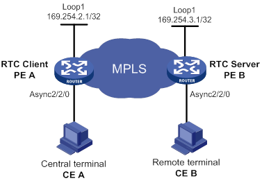
Configuration procedure
1. Configure the RTC server:
# Configure MPLS L3VPN. For more information, see MPLS Configuration Guide.
# Bind Loopback 1 to VPNA.
<PEB> system-view
[PEB] interface loopback 1
[PEB-LoopBack1] ip binding vpn-instance vpna
[PEB-LoopBack1] ip address 169.254.3.1 32
[PEB-LoopBack1] quit
# Enable terminal access.
[PEB] rta server enable
# Configure the listening port number of the RTC server.
[PEB] rta rtc-server listen-port 9000
# Configure the terminal template.
[PEB] rta template rtcs
# Configure VTY 0 on the RTC server.
[PEB-rta-template-rtcs] vty 0 rtc-server remote 169.254.2.1 2
# Bind the VPN instance to the template.
[PEB-rta-template-rtcs] bind vpn-instance vpna
[PEB-rta-template-rtcs] quit
# Configure interface async 2/2/0.
[PEB] interface async 2/2/0
[PEB-Async2/2/0] async mode flow
[PEB-Async2/2/0] rta terminal rtcs 2
2. Configure the RTC client:
# Configure MPLS L3VPN. For more information, see MPLS Configuration Guide.
# Bind Loopback 1 to VPNA.
[PEA] interface loopback 1
[PEA-LoopBack1] ip address 169.254.2.1 32
[PEA-LoopBack1] ip binding vpn-instance vpna
[PEA-LoopBack1] quit
# Enable terminal access.
[PEA] rta server enable
# Configure a terminal template.
[PEA] rta template rtcc
# Configure VTY 0 on the RTC client.
[PEA-rta-template-rtcc] vty 0 rtc-client remote 169.254.3.1 9000
# Bind VPNA to the template.
[PEA-rta-template-rtcc] bind vpn-instance vpna
[PEA-rta-template-rtcc] quit
# Configure interface async 2/2/0.
[PEA] interface async 2/2/0
[PEA-Async2/2/0] async mode flow
[PEA-Async2/2/0] rta terminal rtcc 2
[PEA-Async2/2/0] quit
Verifying the configuration
# Send an instruction from CE A to CE B.
# Check that CE B can receive the instruction, and check that CE A can receive the requested data from CE B.
Asynchronous TCP RTC many-to-one relay configuration example
Network requirements
As shown in Figure 21, Router A and Router C act as TCP_11_Clients and Router B acts as the relay server TCP_N1_Server.
Configure the TCP_11_Clients and TCP_N1_Server to enable terminal A and terminal B to share data:
· Set the RTC listening number to 2000.
· Set the terminal number to 1 on both Router A and the Router C.
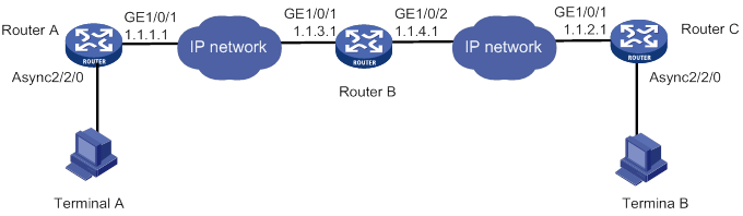
Configuration procedure
1. Configure TCP_11_Client Router A:
# Enable terminal access.
<Sysname> system-view
[Sysname] rta server enable
# Create a terminal template and enter terminal template view.
[Sysname] rta template rtcclient
# Configure the VTY.
[Sysname-rta-template-rtcclient] vty 0 rtc-client remote 1.1.3.1 2000
[Sysname-rta-template-rtcclient] quit
# Apply the template to the interface.
[Sysname] interface async 2/2/0
[Sysname-Async2/2/0] async mode flow
[Sysname-Async2/2/0] rta terminal rtcclient 1
2. Configure TCP_11_Client Router C:
# Enable terminal access.
<Sysname> system-view
[Sysname] rta server enable
# Create a terminal template and enter terminal template view.
[Sysname] rta template rtcclient
# Configure the VTY.
[Sysname-rta-template-rtcclient] vty 0 rtc-client remote 1.1.4.1 2000
[Sysname-rta-template-rtcclient] quit
# Apply the template to the interface.
[Sysname] interface async 2/2/0
[Sysname-Async2/2/0] async mode flow
[Sysname-Async2/2/0] rta terminal rtcclient 1
3. Configure the relay server Router B:
# Enable terminal access relay.
<Sysname> system-view
[Sysname] rta relay enable
# Configure a listening port.
[Sysname] rta relay listen-port 2000
Verifying the configuration
# Check that terminal A and terminal B can receive data from each other.
Synchronous TCP RTC many-to-one relay configuration example
Network requirements
As shown in Figure 22, Router A and Router C act as TCP_11_Clients and Router B acts as the relay server TCP_N1_Server. The TCP_11_Clients are connected to the terminal devices through synchronous serial interface Serial 2/2/0.
Configure the TCP_11_Clients and TCP_N1_Server to enable Terminal A and Terminal B to share data:
· Set the RTC listening number to 2000.
· Set the terminal number to 1 on both Router A and the Router C.
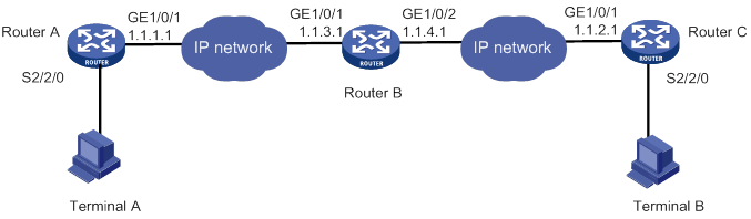
Configuration procedure
1. Configure TCP_11_Client Router A:
# Enable terminal access.
<Sysname> system-view
[Sysname] rta server enable
# Create a terminal template and enter terminal template view.
[Sysname] rta template rtcclient
# Configure the VTY.
[Sysname-rta-template-rtcclient] vty 0 rtc-client remote 1.1.3.1 2000
[Sysname-rta-template-rtcclient] quit
# Apply the template to the interface.
[Sysname] interface serial 2/2/0
[Sysname-Serial2/2/0] link-protocol stlp
[Sysname-Serial2/2/0] rta terminal rtcclient 1
[Sysname-Serial2/2/0] quit
2. Configure TCP_11_Client Router C:
# Enable terminal access.
<Sysname> system-view
[Sysname] rta server enable
# Create a terminal template and enter terminal template view.
[Sysname] rta template rtcclient
# Configure the VTY.
[Sysname-rta-template-rtcclient] vty 0 rtc-client remote 1.1.4.1 2000
[Sysname-rta-template-rtcclient] quit
# Apply the template to the interface.
[Sysname] interface serial 2/2/0
[Sysname-Serial2/2/0] link-protocol stlp
[Sysname-Serial2/2/0] rta terminal rtcclient 1
[Sysname-Serial2/2/0] quit
3. Configure the relay server Router B:
# Enable terminal access relay.
<Sysname> system-view
[Sysname] rta relay enable
# Configure a listening port.
[Sysname] rta relay listen-port 2000
Verifying the configuration
# Check that Terminal A and Terminal B can receive data from each other.
UDP RTC one-to-one backup link configuration example
Network requirements
As shown in Figure 23, Router A acts as a UDP_11_Client, and Router B acts as a UDP_11_Server. Router A is connected to Terminal A through synchronous interface Serial 2/1/0 and Terminal B through synchronous interface Serial 2/1/1.
Configure the UDP RTC backup link function on the routers to enable terminal A and its backup terminal B to monitor the remote terminal C:
· Configure Serial 2/1/0 as the primary interface and Serial 2/1/1 as the backup interface.
· Configure the RTC server to use UDP port 3000 and the RTC client to use UDP port 3001.
· Set the same terminal number to 1 on both the RTC client and the RTC server.
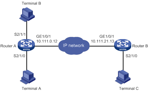
Configuration procedure
1. Configure the UDP_11_Client Router A:
# Enable terminal access.
<Sysname> system-view
[Sysname] rta server enable
# Create a terminal template and enter terminal template view.
[Sysname] rta template rtcclient
# Configure the VTY.
[Sysname-rta-template-rtcclient] vty 0 rtc-client remote 10.111.21.13 remote-port 3000 udp local-port 3001 source 10.111.0.12
[Sysname-rta-template-rtcserver] quit
# Apply the template to the primary interface.
[Sysname] interface serial 2/1/0
[Sysname-Serial2/1/0] link-protocol stlp
[Sysname-Serial2/1/0] rta terminal rtcclient 1
[Sysname-Serial2/1/0] quit
# Apply the template to the backup interface.
[Sysname] interface serial 2/1/1
[Sysname-Serial2/1/1] link-protocol stlp
[Sysname-Serial2/1/1] rta terminal rtcclient 1 backup
2. Configure the UDP_11_Server Router B:
# Enable terminal access.
<Sysname> system-view
[Sysname] rta server enable
# Create a terminal template and enter terminal template view.
[Sysname] rta template rtcserver
# Configure the VTY.
[Sysname-rta-template-rtcserver] vty 0 rtc-server remote 10.111.0.12 remote-port 3001 udp local-port 3000 source 10.111.21.13
[Sysname-rta-template-rtcserver] quit
# Apply the template to the interface.
[Sysname] interface serial 2/1/0
[Sysname-Serial2/1/0] link-protocol stlp
[Sysname-Serial2/1/0] rta terminal rtcserver 1
Verifying the configuration
To verify the backup link function, follow these steps:
1. Send a connection request from Terminal A and Terminal B to Terminal C when both Serial 2/1/0 and Serial 2/1/1 on Router A are in up state.
Expected result: Terminal A can receive data from Terminal C. Terminal B cannot receive data from Terminal C.
2. Shut down Serial 2/1/0 on Router A and send a connection request from Terminal A and Terminal B.
Expected result: Terminal A cannot receive data from Terminal C. Terminal B can receive data from Terminal C.
3. Bring up Serial 2/1/0 on router A and send a connection request from Terminal A and Terminal B.
Expected result: Terminal A can receive data from Terminal C. Terminal B cannot receive data from Terminal C.
UDP RTC one-to-many configuration example
Network requirements
As shown in Figure 24, Router A and Router C act as UDP_11_Clients, and Router B acts as a UDP_1N_Server.
Configure Router A, Router B, and Router C to enable both Terminal A and Terminal C to receive data from Terminal B:
· Configure the RTC server to use UDP port 3000 and the RTC client to use UDP port 3001.
· Set the terminal number to 1 on both the RTC client and the RTC server.
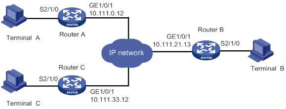
Configuration procedure
1. Configure the UDP_11_Client Router A:
# Enable terminal access.
<Sysname> system-view
[Sysname] rta server enable
# Create a terminal template and enter terminal template view.
[Sysname] rta template rtcclient
# Configure the VTY.
[Sysname-rta-template-rtcclient] vty 0 rtc-client remote 10.111.21.13 remote-port 3000 udp local-port 3001 source 10.111.0.12
[Sysname-rta-template-rtcserver] quit
# Apply the template to the primary interface.
[Sysname] interface serial 2/1/0
[Sysname-Serial2/1/0] link-protocol stlp
[Sysname-Serial2/1/0] rta terminal rtcclient 1
2. Configure the UDP_11_Client Router C:
# Enable terminal access.
<Sysname> system-view
[Sysname] rta server enable
# Create a terminal template and enter terminal template view.
[Sysname] rta template rtcclient
# Configure the VTY.
[Sysname-rta-template-rtcclient] vty 0 rtc-client remote 10.111.21.13 remote-port 3000 udp local-port 3001 source 10.111.33.12
[Sysname-rta-template-rtcserver] quit
# Apply the template to the interface.
[Sysname] interface Serial 2/1/0
[Sysname-Serial2/1/0] link-protocol stlp
[Sysname-Serial2/1/0] rta terminal rtcclient 1
3. Configure the UDP_1N_Server (Router B):
# Enable terminal access.
<Sysname> system-view
[Sysname] rta server enable
# Create a terminal template and enter terminal template view.
[Sysname] rta template rtcserver
# Configure the VTY.
[Sysname-rta-template-rtcserver] vty 0 rtc-multipeer 10.111.21.13 3000
# Configure the IP addresses and port numbers of the two initiators.
[Sysname-rta-template-rtcserver] rtc-multipeer 0 remote 10.111.0.12 3001
[Sysname-rta-template-rtcserver] rtc-multipeer 0 remote 10.111.33.12 3001
[Sysname-rta-template-rtcserver] quit
# Apply the template to the interface.
[Sysname] interface serial 2/1/0
[Sysname-Serial2/1/0] link-protocol stlp
[Sysname-Serial2/1/0] rta terminal rtcserver 1
Verifying the configuration
# Send data from Terminal B to Terminal A and terminal C.
# Check that both Terminal A and Terminal C can receive the data.
Troubleshooting RTC terminal access
Failure to establish a terminal connection
Symptom
The terminal displays that the connection toggles between Established and Establishing state, and ultimately goes down.
Analysis
The initiator and receiver are not configured consistently. Most mistakes result from inconsistent configurations.
Solution
· Verify that the same application mode (many-to-one or one-to-one) is configured on both the initiator and the receiver.
· Verify that the initiator and receiver are configured consistently, and that the configurations comply with the parameter configuration conventions.
· Verify that the router IP address configured on the receiver is the bound IP address if the source address binding is configured on the initiator.
· Verify that the initiator and receiver can reach each other.
Powered terminal state goes down after terminal access is enabled
Symptom
Terminal access is enabled by using the rta server enable command. However, the display rta command displays that the state of a powered terminal is Down.
Analysis
The asynchronous interface is configured with the undo modem command.
Terminal cable or converter failure occurs.
Solution
· Verify that the asynchronous interface is not configured with the undo modem command.
· Verify that the terminal cable is functional.
· Verify that the converter connecting the terminal and the router is wired correctly.
Configuring POS access,11
Configuring the asynchronous TCP RTC one-to-one initiator (TCP_11_Client),39
Configuring the asynchronous TCP RTC one-to-one receiver (TCP_11_Server),43
Configuring the synchronous UDP RTC one-to-many receiver (UDP_1N_Server),48
Configuring the synchronous UDP RTC one-to-one initiator (UDP_11_Client),46
Configuring the synchronous UDP RTC one-to-one receiver (UDP_11_Server),47
Configuring the TCP RTC many-to-one relay server (TCP_N1_Server),46
Displaying and maintaining POS access,22
Displaying and maintaining RTC terminal access,50
Feature and hardware compatibility,39
Feature and hardware compatibility,10
License restrictions,11
Overview,33
Overview,1
POS access configuration examples,22
RTC terminal access configuration examples,50
RTC terminal access configuration task list,39
Setting the RTC version,49
Troubleshooting RTC terminal access,60
