- Table of Contents
- Related Documents
-
| Title | Size | Download |
|---|---|---|
| 01-Text | 604.97 KB |
Configuration restrictions and guidelines
Displaying and maintaining bulk interface configuration
Configuring Ethernet interfaces
Command and hardware compatibility
Configuring common Ethernet interface settings
Configuring a combo interface (single combo interface)
Configuring basic settings of an Ethernet interface or subinterface
Configuring the link mode of an Ethernet interface
Configuring jumbo frame support
Configuring dampening on an Ethernet interface
Enabling loopback testing on an Ethernet interface
Configuring generic flow control on an Ethernet interface
Setting the statistics polling interval
Configuring a Layer 2 Ethernet interface
Setting the MDIX mode of an Ethernet interface
Configuring a Layer 3 Ethernet interface or subinterface
Setting the MTU for an Ethernet interface or subinterface
Setting the MAC address of an Ethernet interface
Displaying and maintaining an Ethernet interface
Configuring a serial interface
Configuring an asynchronous serial interface
Configuring a synchronous serial interface
Displaying and maintaining serial interfaces
Displaying and maintaining AM interfaces
Displaying and maintaining FCM interfaces
Configuring an ISDN BRI interface
Displaying and maintaining ISDN BRI interfaces
Configuring a CE1/PRI interface
Configuring a CE1/PRI interface in E1 mode·
Configuring a CE1/PRI interface in CE1 mode
Configuring a CE1/PRI interface in PRI mode
Configuring other CE1/PRI interface parameters
Displaying and maintaining CE1/PRI interfaces
Configuring a CT1/PRI interface
Configuring a CT1/PRI interface in CT1 mode
Configuring a CT1/PRI interface in PRI mode
Configuring other CT1/PRI interface parameters
Starting a BERT test on a CT1/PRI interface
Displaying and maintaining CT1/PRI interfaces
Configuring an E1-F interface in framed mode
Configuring an E1-F interface in unframed mode
Configuring other E1-F interface parameters
Displaying and maintaining E1-F interfaces
Starting a BERT test on a T1-F interface·
Displaying and maintaining T1-F interfaces
Configuring a CE3 interface in E3 mode·
Configuring a CE3 interface in CE3 mode
Displaying and maintaining CE3 interfaces
Configuring a CT3 interface in T3 mode·
Configuring a CT3 interface in CT3 mode
Displaying and maintaining CT3 interfaces
Configuring a standard POS interface
Configuring a POS subinterface
Configuring B1/B2/B3 alarms for standard POS interfaces
Displaying and maintaining POS interfaces
POS interface configuration examples
Directly connecting routers through POS interfaces
Connecting routers through POS interfaces across a Frame Relay network
Troubleshooting POS interfaces
CPOS interface application scenarios
CPOS interface configuration task list
Configuring the operating mode of an interface module
Configuring basic functions of a CPOS interface
Displaying and maintaining CPOS interfaces
CPOS-E1 interface configuration example
Troubleshooting CPOS interfaces
Feature and hardware compatibility
Configuring an ATM OC-3c/STM-1 interface
Configuring a G.SHDSL interface
Configuring an ATM subinterface
Configuring an EFM subinterface
Displaying and maintaining ATM interfaces
Troubleshooting ATM interfaces
Frequent packet dropping, CRC check errors, and interface state errors
Troubleshooting DSL interfaces
Configuring loopback, null, and inloopback interfaces
Configuring a loopback interface
Configuring an inloopback interface·
Displaying and maintaining loopback, null, and inloopback interfaces
Bulk configuring interfaces
Configuration restrictions and guidelines
When you bulk configure interfaces in interface range view, follow these restrictions and guidelines:
· In interface range view, only commands supported by the first interface in the specified interface list are available for configuration.
· Before you configure an interface as the first interface in an interface range, make sure you can enter the view of the interface by using the interface interface-type { interface-number | interface-number.subnumber } command.
· Do not assign both an aggregate interface and any of its member interfaces to an interface range. Some commands, after being executed on both an aggregate interface and its member interfaces, can break up the aggregation.
· Understand that the more interfaces you specify in an interface range, the longer the command execution time.
· To guarantee bulk interface configuration performance, configure fewer than 1000 interface range names.
· After a command is executed in interface range view, one of the following situations might occur:
? The system displays an error message and stays in interface range view. It means that the execution failed on one or multiple member interfaces.
- If the execution failed on the first member interface, the command is not executed on any member interfaces.
- If the execution failed on a non-first member interface, the command takes effect on the remaining member interfaces.
? The system returns to system view. It means that:
- The command is supported in both system view and interface view.
- The execution failed on a member interface in interface range view and succeeded in system view.
- The command is not executed on the subsequent member interfaces.
You can use the display this command to verify the configuration in interface view of each member interface. In addition, if the configuration in system view is not needed, use the undo form of the command to remove the configuration.
Configuration procedure
|
Step |
Command |
Remarks |
|
1. Enter system view. |
system-view |
N/A |
|
2. Enter interface range view. |
· interface range { interface-type interface-number [ to interface-type interface-number ] } &<1-5> · interface range name name [ interface { interface-type interface-number [ to interface-type interface-number ] } &<1-5> ] |
By using the interface range name command, you assign a name to an interface range and can specify this name rather than the interface range to enter the interface range view. |
|
3. (Optional.) Display commands available for the first interface in the interface range. |
Enter a question mark (?) at the interface range prompt. |
N/A |
|
4. Use available commands to configure the interfaces. |
Available commands depend on the interface. |
N/A |
|
5. (Optional.) Verify the configuration. |
display this |
N/A |
Displaying and maintaining bulk interface configuration
Execute the display command in any view.
|
Task |
Command |
|
Display information about the interface ranges created by using the interface range name command. |
display interface range [ name name ] |
Configuring Ethernet interfaces
Your device supports the following types of Ethernet interfaces:
· Layer 2 Ethernet interfaces—Physical Ethernet interfaces operating at the data link layer (Layer 2) to switch packets.
· Layer 3 Ethernet interfaces—Physical Ethernet interfaces operating at the network layer (Layer 3) to route packets. You can assign an IP address to a Layer 3 Ethernet interface.
· Layer-configurable Ethernet interfaces—Physical Ethernet interfaces that can be configured to operate in bridge mode as Layer 2 Ethernet interfaces or in route mode as Layer 3 Ethernet interfaces.
· Layer 3 Ethernet subinterfaces—Logical interfaces operating at the network layer. You can assign an IP address to a Layer 3 Ethernet subinterface. To enable a Layer 3 Ethernet interface to transport packets for multiple VLANs, you must create Layer 3 subinterfaces on the Layer 3 Ethernet interface.
This feature is supported only on devices with related interfaces. For information about interfaces on the device, see the installation guide and the interface module guide.
Command and hardware compatibility
Commands and descriptions for centralized devices apply to the following routers:
· MSR810/810-W/810-W-DB/810-LM/810-W-LM/810-10-PoE/810-LM-HK/810-W-LM-HK/810-LMS/810-LUS.
· MSR2600-6-X1/2600-10-X1.
· MSR 2630.
· MSR3600-28/3600-51.
· MSR3600-28-SI/3600-51-SI.
· MSR3610-X1/3610-X1-DP/3610-X1-DC/3610-X1-DP-DC.
· MSR 3610/3620/3620-DP/3640/3660.
· MSR810-LM-GL/810-W-LM-GL/830-6EI-GL/830-10EI-GL/830-6HI-GL/830-10HI-GL/2600-6-X1-GL/3600-28-SI-GL.
Commands and descriptions for distributed devices apply to the following routers:
· MSR5620.
· MSR 5660.
· MSR 5680.
Configuring common Ethernet interface settings
This section describes the settings common to Layer 2 Ethernet interfaces, Layer 3 Ethernet interfaces, and Layer 3 Ethernet subinterfaces. For more information about the settings specific to Layer 2 Ethernet interfaces, see "Configuring a Layer 2 Ethernet interface." For more information about the settings specific to Layer 3 Ethernet interfaces or subinterfaces, see "Configuring a Layer 3 Ethernet interface or subinterface."
Configuring a combo interface (single combo interface)
A combo interface is a logical interface that physically comprises one fiber combo port and one copper combo port. The two ports share one forwarding channel and one interface view. As a result, they cannot work simultaneously. When you activate one port, the other port is automatically disabled. In the interface view, you can activate the fiber or copper combo port, and configure other port attributes such as the interface rate and duplex mode.
Configuration prerequisites
Before you configure combo interfaces, complete the following tasks:
· Determine the combo interfaces on your device. Identify the two physical interfaces that belong to each combo interface according to the marks on the device panel.
· Use the display interface command to determine which port (fiber or copper) of each combo interface is active:
? If the copper port is active, the output includes "Media type is twisted pair, Port hardware type is 1000_BASE_T."
? If the fiber port is active, the output does not include this information.
Also, you can use the display this command in the view of each combo interface to display the combo interface configuration:
? If the fiber port is active, the combo enable fiber command exists in the output.
? If the copper port is active, the combo enable fiber command does not exist in the output.
Changing the active port of a combo interface
|
Step |
Command |
Remarks |
|
1. Enter system view. |
system-view |
N/A |
|
2. Enter Ethernet interface view. |
interface interface-type interface-number |
N/A |
|
3. Activate the copper combo port or fiber combo port. |
combo enable { copper | fiber } |
By default, the copper combo port is active. |
Configuring basic settings of an Ethernet interface or subinterface
You can configure an Ethernet interface to operate in one of the following duplex modes:
· Full-duplex mode—The interface can send and receive packets simultaneously.
· Half-duplex mode—The interface can only send or receive packets at a given time.
· Autonegotiation mode—The interface negotiates a duplex mode with its peer.
You can set the speed of an Ethernet interface or enable it to automatically negotiate a speed with its peer.
Configuring an Ethernet interface
|
Step |
Command |
Remarks |
|
1. Enter system view. |
system-view |
N/A |
|
2. Enter Ethernet interface view. |
interface interface-type interface-number |
N/A |
|
3. Set the description for the Ethernet interface. |
description text |
The default setting is interface-name Interface. For example, GigabitEthernet1/0/1 Interface. |
|
4. Set the duplex mode for the Ethernet interface. |
duplex { auto | full | half } |
By default, Ethernet interfaces operate in auto mode. Fiber ports do not support the half keyword. |
|
5. Set the speed for the Ethernet interface. |
speed { 10 | 100 | 1000 | 10000 | auto } |
For the support of an Ethernet interface for this command, see Interface Command Reference. The default setting is auto for Ethernet interfaces. |
|
6. Set the expected bandwidth for the Ethernet interface. |
bandwidth bandwidth-value |
By default, the expected bandwidth (in kbps) is the interface baud rate divided by 1000. |
|
7. Restore the default settings for the Ethernet interface. |
default |
N/A |
|
8. Bring up the Ethernet interface. |
undo shutdown |
By default, Ethernet interfaces are in up state. The shutdown and loopback commands are mutually exclusive. |
Configuring an Ethernet subinterface
When you configure an Ethernet subinterface, follow these restrictions and guidelines:
· To transmit packets between a local Ethernet subinterface and a remote Ethernet subinterface, configure them with the same subinterface number and VLAN ID.
· Before creating a Layer 3 Ethernet subinterface, do not reserve a resource for the VLAN interface whose interface number is the subinterface number. After you reserve a VLAN interface resource, do not create a Layer 3 Ethernet subinterface whose subinterface number is the VLAN interface number. A Layer 3 Ethernet subinterface uses the VLAN interface resource in processing tagged packets whose VLAN ID matches the subinterface number.
To configure an Ethernet subinterface:
|
Step |
Command |
Remarks |
|
1. Enter system view. |
system-view |
N/A |
|
2. Create an Ethernet subinterface. |
interface interface-type interface-number.subnumber |
N/A |
|
3. Set the description for the Ethernet subinterface. |
description text |
The default setting is interface-name Interface. For example, GigabitEthernet1/0/1.1 Interface. |
|
4. Restore the default settings for the Ethernet subinterface. |
default |
N/A |
|
5. Set the expected bandwidth for the Ethernet subinterface. |
bandwidth bandwidth-value |
By default, the expected bandwidth (in kbps) is the interface baud rate divided by 1000. |
|
6. Bring up the Ethernet subinterface. |
undo shutdown |
By default, Ethernet subinterfaces are in up state. The shutdown and loopback commands are mutually exclusive. |
Configuring the link mode of an Ethernet interface
|
|
CAUTION: After you change the link mode of an Ethernet interface, all commands (except the shutdown and combo enable commands) on the Ethernet interface are restored to their defaults in the new link mode. |
Ethernet interfaces operate differently depending on the hardware structure of interface cards:
· Some Ethernet interfaces can operate only as Layer 2 Ethernet interfaces (in bridge mode).
· Some Ethernet interfaces can operate only as Layer 3 Ethernet interfaces (in route mode).
· Some Ethernet interfaces can operate either as Layer 2 or Layer 3 Ethernet interfaces. You can set the link mode to bridge or route for these Ethernet interfaces.
To configure the link mode of an Ethernet interface:
|
Step |
Command |
Remarks |
|
1. Enter system view. |
system-view |
N/A |
|
2. Enter Ethernet interface view. |
interface interface-type interface-number |
N/A |
|
3. Configure the link mode of the Ethernet interface. |
port link-mode { bridge | route } |
Support for the link modes of Ethernet interfaces depends on the interface card model. |
Configuring jumbo frame support
Jumbo frames are frames larger than a device-specific size and are typically received by an Ethernet interface during high-throughput data exchanges, such as file transfers.
The Ethernet interface processes jumbo frames in the following ways:
· When the Ethernet interface is configured to deny jumbo frames (by using the undo jumboframe enable command), the Ethernet interface discards jumbo frames.
· When the Ethernet interface is configured with jumbo frame support, the Ethernet interface performs the following operations:
? Processes jumbo frames within the specified length.
? Discards jumbo frames that exceed the specified length.
To configure jumbo frame support in interface view:
|
Step |
Command |
|
1. Enter system view. |
system-view |
|
2. Enter Ethernet interface view. |
interface interface-type interface-number |
|
3. Configure jumbo frame support. |
jumboframe enable [ size ] |
Configuring dampening on an Ethernet interface
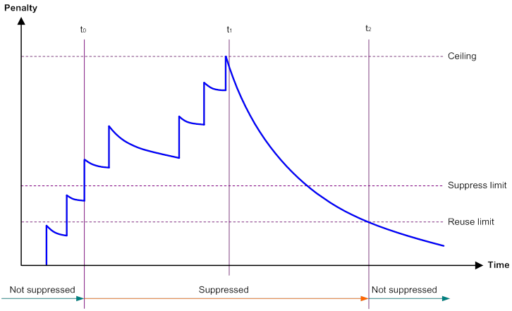
The interface dampening feature uses an exponential decay mechanism to prevent excessive interface flapping events from adversely affecting routing protocols and routing tables in the network. Suppressing interface state change events protects the system resources.
If an interface is not dampened, its state changes are reported. For each state change, the system also generates an SNMP trap and log message.
After a flapping interface is dampened, it does not report its state changes to the CPU. For state change events, the interface only generates SNMP trap and log messages.
Parameters
· Penalty—The interface has an initial penalty of 0. When the interface flaps, the penalty increases by 1000 for each down event. It does not increase for up events.
· Ceiling—The penalty stops increasing when it reaches the ceiling.
· Suppress-limit—The accumulated penalty that triggers the device to dampen the interface. In dampened state, the interface does not report its state changes to the CPU. For state change events, the interface only generates SNMP traps and log messages.
· Reuse-limit—When the accumulated penalty decreases to this reuse threshold, the interface is not dampened. Interface state changes are reported to the upper layers. For each state change, the system also generates an SNMP trap and log message.
· Decay—The amount of time (in seconds) after which a penalty is decreased.
· Max-suppress-time—The maximum amount of time the interface can be dampened. If the penalty is still higher than the reuse threshold when this timer expires, the penalty stops increasing for down events.
When configuring the dampening command, follow these rules to set the values mentioned above:
· The ceiling is equal to 2(Max-suppress-time/Decay) × reuse-limit. It is not user configurable.
· The configured suppress limit is lower than or equal to the ceiling.
· The ceiling is lower than or equal to the maximum suppress limit supported.
Figure 1 shows the change rule of the penalty value. The lines t0 and t2 indicate the start time and end time of the suppression, respectively. The period from t0 to t2 indicates the suppression period, t0 to t1 indicates the max-suppress-time, and t1 to t2 indicates the complete decay period.
Figure 1 Change rule of the penalty value
Configuration restrictions and guidelines
When you configure dampening on an Ethernet interface, follow these restrictions and guidelines:
· The dampening command and the link-delay command cannot be configured together on an interface.
· The dampening command does not take effect on the administratively down events. When you execute the shutdown command, the penalty restores to 0, and the interface reports the down event to the upper-layer protocols.
· Do not enable the dampening feature on an interface with RRPP, MSTP, or Smart Link enabled.
Configuration procedure
To configure dampening on an Ethernet interface:
|
Step |
Command |
Remarks |
|
1. Enter system view. |
system-view |
N/A |
|
2. Enter Ethernet interface view. |
interface interface-type interface-number |
N/A |
|
3. Enable dampening on the interface. |
dampening [ half-life reuse suppress max-suppress-time ] |
By default, interface dampening is disabled on Ethernet interfaces. |
Enabling loopback testing on an Ethernet interface
|
|
CAUTION: After you enable this feature on an Ethernet interface, the interface does not forward data traffic. |
Perform this task to determine whether an Ethernet link works correctly.
Internal loopback testing tests the device where the Ethernet interface resides. The Ethernet interface sends outgoing packets back to the local device. If the device fails to receive the packets, the device fails.
Configuration restrictions and guidelines
· The shutdown and loopback commands are mutually exclusive.
· After you enable this feature on an Ethernet interface, the Ethernet interface switches to full duplex mode. After you disable this feature, the Ethernet interface restores to its duplex setting.
Configuration procedure
To enable loopback testing on an Ethernet interface:
|
Step |
Command |
|
1. Enter system view. |
system-view |
|
2. Enter Ethernet interface view. |
interface interface-type interface-number |
|
3. Enable loopback testing. |
loopback internal |
Configuring generic flow control on an Ethernet interface
To avoid dropping packets on a link, you can enable generic flow control at both ends of the link. When traffic congestion occurs at the receiving end, the receiving end sends a flow control (Pause) frame to ask the sending end to suspend sending packets. Generic flow control includes the following types:
· TxRx-mode generic flow control—Enabled by using the flow-control command. With TxRx-mode generic flow control enabled, an interface can both send and receive flow control frames:
? When congestion occurs, the interface sends a flow control frame to its peer.
? When the interface receives a flow control frame from its peer, it suspends sending packets to its peer.
· Rx-mode generic flow control—Enabled by using the flow-control receive enable command. With Rx-mode generic flow control enabled, an interface can receive flow control frames, but it cannot send flow control frames:
? When congestion occurs, the interface cannot send flow control frames to its peer.
? When the interface receives a flow control frame from its peer, it suspends sending packets to its peer.
To handle unidirectional traffic congestion on a link, configure the flow-control receive enable command at one end and the flow-control command at the other end. To enable both ends of a link to handle traffic congestion, configure the flow-control command at both ends.
To enable generic flow control on an Ethernet interface:
|
Step |
Command |
Remarks |
|
1. Enter system view. |
system-view |
N/A |
|
2. Enter Ethernet interface view. |
interface interface-type interface-number |
N/A |
|
3. Enable generic flow control. |
·
Enable TxRx-mode generic flow control: ·
Enable Rx-mode generic flow control: |
By default, generic flow control is disabled on an Ethernet interface. For the devices' support for the flow-control and flow-control receive enable commands, see Interface Command Reference. |
Setting the statistics polling interval
As a best practice, use the default setting when you set the statistics polling interval in system view. A short statistics polling interval might decrease the system performance and result in inaccurate statistics.
To set the statistics polling interval:
|
Step |
Command |
Remarks |
|
1. Enter system view. |
system-view |
N/A |
|
2. Set the statistics polling interval. |
flow-interval interval |
The default statistics polling interval is 300 seconds. |
To display the interface statistics collected in the last statistics polling interval, use the display interface command. To clear the interface statistics, use the reset counters interface command.
Configuring a Layer 2 Ethernet interface
Configuring storm suppression
The storm suppression feature ensures that the size of a particular type of traffic (broadcast, multicast, or unknown unicast traffic) does not exceed the threshold on an interface. When the broadcast, multicast, or unknown unicast traffic on the interface exceeds this threshold, the system discards packets until the traffic drops below this threshold.
The, broadcast-suppression, multicast-suppression, and unicast-suppression commands can suppress storm on an interface. They suppress traffic in hardware.
Configuration restrictions and guidelines
The configured suppression threshold value in pps or kbps might be converted into a multiple of the step value supported by the chip. As a result, the effective suppression threshold might be different from the configured one. For information about the suppression threshold that takes effect, see the prompt on the device.
Configuration procedure
To set storm suppression thresholds on an Ethernet interface or subinterface:
|
Step |
Command |
Remarks |
|
1. Enter system view. |
system-view |
N/A |
|
2. Enter Ethernet interface view. |
interface interface-type interface-number |
N/A |
|
3. Enable broadcast suppression and set the broadcast suppression threshold. |
broadcast-suppression { ratio | pps max-pps | kbps max-kbps } |
By default, broadcast suppression is disabled. For the devices' support for the ratio argument and kbps max-kbps option, see Interface Command Reference. |
|
4. Enable multicast suppression and set the multicast suppression threshold. |
multicast-suppression { ratio | pps max-pps | kbps max-kbps } |
By default, multicast suppression is disabled. For the devices' support for the ratio argument and kbps max-kbps option, see Interface Command Reference. |
|
5. Enable unknown unicast suppression and set the unknown unicast suppression threshold. |
unicast-suppression { ratio | pps max-pps | kbps max-kbps } |
By default, unknown unicast suppression is disabled. For the devices' support for the ratio argument and kbps max-kbps option, see Interface Command Reference. |
Setting the MDIX mode of an Ethernet interface
|
|
IMPORTANT: Fiber ports do not support the MDIX mode setting. |
A physical Ethernet interface has eight pins, each of which plays a dedicated role. For example, pins 1 and 2 transmit signals, and pins 3 and 6 receive signals. You can use both crossover and straight-through Ethernet cables to connect copper Ethernet interfaces. To accommodate these types of cables, a copper Ethernet interface can operate in one of the following Medium Dependent Interface-Crossover (MDIX) modes:
· MDIX mode—Pins 1 and 2 are receive pins and pins 3 and 6 are transmit pins.
· MDI mode—Pins 1 and 2 are transmit pins and pins 3 and 6 are receive pins.
· AutoMDIX mode—The interface negotiates pin roles with its peer.
|
|
NOTE: This feature does not take effect on pins 4, 5, 7, and 8 of physical Ethernet interfaces. · Pins 4, 5, 7, and 8 of interfaces operating at 10 Mbps or 100 Mbps do not receive or transmit signals. · Pins 4, 5, 7, and 8 of interfaces operating at 1000 Mbps or higher rates receive and transmit signals. |
To enable a copper Ethernet interface to communicate with its peer, set the MDIX mode of the interface by following these guidelines:
· Typically, set the MDIX mode of the interface to AutoMDIX. Set the MDIX mode of the interface to MDI or MDIX only when the device cannot determine the cable type.
· When a straight-through cable is used, configure the interface to operate in an MDIX mode different than its peer.
· When a crossover cable is used, perform one of the following tasks:
? Configure the interface to operate in the same MDIX mode as its peer.
? Configure either end to operate in AutoMDIX mode.
To set the MDIX mode of an Ethernet interface:
|
Step |
Command |
Remarks |
|
1. Enter system view. |
system-view |
N/A |
|
2. Enter Ethernet interface view. |
interface interface-type interface-number |
N/A |
|
3. Set the MDIX mode of the Ethernet interface. |
mdix-mode { automdix | mdi | mdix } |
By default, a copper Ethernet interface operates in auto mode to negotiate pin roles with its peer. |
Configuring a Layer 3 Ethernet interface or subinterface
Setting the MTU for an Ethernet interface or subinterface
The maximum transmission unit (MTU) of an Ethernet interface affects the fragmentation and reassembly of IP packets on the interface. Typically, you do not need to modify the MTU of an interface.
To set the MTU for an Ethernet interface or subinterface:
|
Step |
Command |
Remarks |
|
1. Enter system view. |
system-view |
N/A |
|
2. Enter Ethernet interface or subinterface view. |
interface interface-type { interface-number | interface-number.subnumber } |
N/A |
|
3. Set the MTU of the Ethernet interface or subinterface. |
mtu size |
The default setting is 1500 bytes. |
Setting the MAC address of an Ethernet interface
In a network, when the Layer 3 Ethernet interfaces of different devices have the same MAC address, the devices might fail to communicate correctly. To eliminate the MAC address conflicts, use the mac-address command to modify the MAC addresses of Layer 3 Ethernet interfaces.
To set the MAC address of an Ethernet interface:
|
Step |
Command |
Remarks |
|
1. Enter system view. |
system-view |
N/A |
|
2. Enter Ethernet interface view. |
interface interface-type interface-number |
N/A |
|
3. Set the MAC address of the Ethernet interface. |
mac-address mac-address |
The default MAC address of a Layer 3 Ethernet interface varies by device model. |
Displaying and maintaining an Ethernet interface
Execute display commands in any view and reset commands in user view.
|
Task |
Command |
|
Display interface traffic statistics. |
display counters { inbound | outbound } interface [ interface-type [ interface-number | interface-number.subnumber ] ] |
|
Display traffic rate statistics of interfaces in up state over the last statistics polling interval. |
display counters rate { inbound | outbound } interface [ interface-type [ interface-number | interface-number.subnumber ] ] |
|
Display the operational and status information of the specified interfaces. |
display interface [ interface-type [ interface-number | interface-number.subnumber ] ] [ brief [ description | down ] ] |
|
Display information about dropped packets on the specified interfaces. |
display packet-drop { interface [ interface-type [ interface-number ] ] | summary } |
|
Display the Ethernet module statistics (Centralized devices in standalone mode). |
display ethernet statistics |
|
Display the Ethernet module statistics (Distributed devices in standalone mode/centralized devices in IRF mode). |
display ethernet statistics slot slot-number |
|
Display the Ethernet module statistics (Distributed devices in IRF mode). |
display ethernet statistics chassis chassis-number slot slot-number |
|
Clear interface or subinterface statistics. |
reset counters interface [ interface-type [ interface-number | interface-number.subnumber ] ] |
|
Clear the statistics of dropped packets on the specified interfaces. |
reset packet-drop interface [ interface-type [ interface-number ] ] |
|
Clear the Ethernet module statistics (Centralized devices in standalone mode). |
reset ethernet statistics |
|
Clear the Ethernet module statistics (Distributed devices in standalone mode/centralized devices in IRF mode). |
reset ethernet statistics [ slot slot-number ] |
|
Clear the Ethernet module statistics (Distributed devices in IRF mode). |
reset ethernet statistics [ chassis chassis-number slot slot-number] |
Configuring WAN interfaces
This chapter describes how to configure interfaces for connecting to WAN networks, including Frame Relay, ATM, and ISDN. Available WAN interfaces include the asynchronous serial interface, synchronous serial interface, ATM interface, ISDN BRI interface, and CE1/PRI interface.
For more information about ATM interfaces, see "Configuring ATM interfaces."
This feature is supported only on devices with related interfaces. For information about interfaces on the device, see the installation guide and the interface module guide.
Configuring a serial interface
Asynchronous serial interface
The following types of asynchronous serial interfaces are available:
· Synchronous/asynchronous serial interface operating in asynchronous mode. The interface type name is Serial.
· Dedicated asynchronous serial interface. The interface type name is Async.
You can connect a modem or ISDN terminal adapter to an asynchronous serial interface for dial-up connection.
An asynchronous serial interface can operate in protocol or flow mode.
· Protocol mode—Data is transmitted in packets. The link layer protocol can only be PPP. The network layer protocol is typically IP.
· Flow mode—Data is transmitted as character flows. This mode is typically used in human-machine interaction scenarios such as dial-up access. After the physical connection is established, you can send commands to set up a link with the asynchronous serial interface, and then configure the device.
Synchronous serial interface
Synchronous serial interfaces refer to synchronous/asynchronous serial interfaces operating in synchronous mode. They provide serial communication channels for synchronous data transmission. The interface type name is Serial.
A synchronous serial interface operates in DCE or DTE mode. Two directly connected synchronous serial interfaces must operate in different modes.
· In DCE mode, the interface provides timing for synchronization and sets the baud rate.
· In DTE mode, the interface accepts the timing signal and baud rate from the DCE.
The synchronous serial interfaces on the device typically operate as DTE.
You can connect a synchronous interface to various types of cables, including V.24, V.35, X.21, RS449, and RS530. Typically, the device can automatically recognize the cable type and select electrical properties.
The synchronous serial interface supports multiple data link layer protocols, including PPP, HDLC, Frame Relay, and STLP. The interface supports network layer protocols, such as IP.
Configuring an asynchronous serial interface
This section only describes the interface properties configuration. Depending on the network requirements, you might also need to configure PPP, DDR, IP address, firewall, and interface backup.
To configure an asynchronous serial interface:
|
Step |
Command |
Remarks |
|
1. Enter system view. |
system-view |
N/A |
|
2. Enter asynchronous serial interface view. |
interface async interface-number or interface serial interface-number |
N/A |
|
3. (Optional.) Configure the interface description. |
description text |
By default, the description of an asynchronous serial interface is interface name Interface, for example, Serial2/1/0 Interface. |
|
4. Configure a synchronous or asynchronous serial interface to operate as an asynchronous serial interface. |
physical-mode async |
By default, a synchronous or asynchronous serial interface operates as a synchronous serial interface. Skip this step if the interface is an asynchronous interface. |
|
5. Set the link layer protocol. |
link-protocol ppp |
The default is PPP. |
|
6. Set the operating mode. |
async mode { flow | protocol } |
The default is the protocol mode. |
|
7. (Optional.) Enable level detection. |
detect dsr-dtr |
By default, level detection is enabled. |
|
8. (Optional.) Enable local loopback. |
loopback |
By default, local loopback is disabled. |
|
9. Set the MTU. |
mtu size |
The default setting is 1500 bytes. |
|
10. Set the keepalive interval. |
timer-hold seconds |
The default setting is 10 seconds. |
|
11. Set the maximum number of keepalive attempts. |
timer-hold retry retries |
The default setting is 5. The interface determines that the remote end is down if it does not receive a keepalive response after the maximum number of keepalive attempts have been made. |
|
12. (Optional.) Eliminate the pulses with a width less than 3.472 μs. |
eliminate-pulse |
By default, the pulses with a width less than 1.472 μs are eliminated. |
|
13. Set the MRU for an interface operating in flow mode. |
phy-mru mrusize |
The default MRU is 1700 bytes. |
|
14. (Optional.) Set the intended bandwidth for the asynchronous serial interface. |
bandwidth bandwidth-value |
By default, the expected bandwidth (in kbps) is the interface baud rate divided by 1000. |
|
15. (Optional.) Restore the default settings for the asynchronous serial interface. |
default |
N/A |
|
16. Bring up the asynchronous serial interface. |
undo shutdown |
By default, an asynchronous serial interface is up. |
Configuring a synchronous serial interface
This section only describes the interface properties configuration. Depending on the network requirements, you might also need to configure the PPP, HDLC, Frame Relay, DDR, IP address, firewall, and interface backup.
To configure a synchronous serial interface:
|
Step |
Command |
Remarks |
|
|
1. Enter system view. |
system-view |
N/A |
|
|
2. Enter synchronous serial interface view. |
interface serial interface-number |
N/A |
|
|
3. Configure a synchronous or asynchronous serial interface to operate as a synchronous serial interface. |
physical-mode sync |
By default, a synchronous or asynchronous serial interface operates as a synchronous serial interface. |
|
|
4. (Optional.) Configure the interface description. |
description text |
By default, the description of a synchronous serial interface is interface name Interface, for example, Serial2/1/0 Interface. |
|
|
5. Set the link layer protocol. |
link-protocol { fr | hdlc | ppp | mfr | stlp } |
The default is PPP. |
|
|
6. Set the digital signal coding format. |
code { nrz | nrzi } |
The default is non-return-to-zero (NRZ). |
|
|
7. Set the baud rate. |
·
On DCE side: ·
On DTE side: |
The default is 64000 bps. |
|
|
8. Set the clock selection mode. |
·
On DTE side: ·
On DCE side: |
The default is dceclk1 for the DCE side and dteclk1 for the DTE side. |
|
|
9. (Optional.) Set transmit-clock or receive-clock signal inversion on the DTE side. |
invert { transmit-clock | receive-clock } |
By default, clock signal inversion is disabled. |
|
|
10. Set the MTU. |
mtu size |
The default is 1500 bytes. |
|
|
11. Set the CRC mode. |
crc { 16 | 32 | none } |
The default is 16-bit CRC. |
|
|
12. Set the number of interframe filling tags. |
itf number number |
The default is four. |
|
|
13. (Optional.) Enable level detection. |
detect dsr-dtr |
By default, level detection is enabled. |
|
|
14. (Optional.) Enable data carrier detection (DCD). |
detect dcd |
By default, DCD is enabled. |
|
|
15. (Optional.) Enable local loopback. |
loopback |
By default, local loopback is disabled. |
|
|
16. Set the keepalive interval. |
timer-hold seconds |
The default setting is 10 seconds. |
|
|
17. Set the maximum number of keepalive attempts. |
timer-hold retry retries |
The default setting is 5. The interface determines that the remote end is down if it does not receive a keepalive response after the maximum number of keepalive attempts have been made. |
|
|
18. Set the line idle-code. |
idle-code { 7e | ff } |
The default is 0x7E. |
|
|
19. (Optional.) Enable RTS signal reverse. |
reverse-rts |
By default, RTS signal reverse is disabled. |
|
|
20. (Optional.) Set the intended bandwidth for the synchronous serial interface. |
bandwidth bandwidth-value |
By default, the expected bandwidth (in kbps) is the interface baud rate divided by 1000. |
|
|
21. (Optional.) Restore the default settings for the synchronous serial interface. |
default |
N/A |
|
|
22. Bring up the synchronous serial interface. |
undo shutdown |
By default, a synchronous serial interface is up. |
|
|
23. (Optional.) Initiate the loopback test on the synchronous serial interface. |
loopback-test [ -c count | -p { pattern | special { ascending | descending | random } } | -s packetsize | -t timeout ] * interface interface-type interface-number |
This command is available only on synchronous serial interfaces that are created for E1, T1, E1-F, and T1-F interfaces. |
|
Configuring a subinterface
|
Step |
Command |
Remarks |
|
1. Enter system view. |
system-view |
N/A |
|
2. Create a subinterface and enter its view. |
interface serial interface-number.subnumber [ p2mp | p2p ] |
A subinterface can be created on a serial interface only when the data link layer protocol of the serial interface is FR. |
|
3. (Optional.) Configure the interface description. |
description text |
By default, the description of a subinterface is interface-name Interface. |
|
4. (Optional.) Set the MTU. |
mtu size |
The default MTU is 1500 bytes. |
|
5. (Optional.) Set the expected bandwidth for the subinterface. |
bandwidth bandwidth-value |
By default, the expected bandwidth (in kbps) is the interface baud rate divided by 1000. |
|
6. (Optional.) Restore the default settings for the subinterface. |
default |
N/A |
|
7. Bring up the subinterface. |
undo shutdown |
By default, a subinterface is up. |
Displaying and maintaining serial interfaces
Execute display commands in any view and reset commands in user view.
|
Task |
Command |
|
Display serial interface information. |
display interface [ serial [ interface-number ] ] [ brief [ description | down ] ] |
|
Display information about asynchronous serial interfaces. |
display interface [ async [ interface-number ] ] [ brief [ description | down ] |
|
Clear statistics for serial interfaces. |
reset counters interface [ serial [ interface-number ] ] |
|
Clear statistics for asynchronous serial interfaces. |
Configuring an AM interface
The analog modem (AM) interface combines the functionality of the asynchronous serial interface and analog modem. The AM interface supports most of the commands available on asynchronous serial interfaces and modems. When you configure an AM interface, you can treat it as a special asynchronous serial interface.
AM interfaces provide dial-in and dial-out services for analog dial-up users. The actual connect rates depend on the network conditions, including the line quality and connection protocol.
The AM interface can provide the following maximum downstream and upstream rates:
· If the peer (typically an ISP) uses a digital modem, the AM interface can use the V.90 Modem standard to set up connections. The maximum downstream rate is 56 kbps, and the maximum upstream rate is 33.6 kbps.
· If the peer (typically a subscriber) uses an analog modem (or an AM interface), the AM interface can use the V.34 Modem standard to set up connections. The maximum downstream and upstream rates are both 33.6 kbps.
Configuration procedure
The AM interface supports all commands available on the asynchronous interface and the modem, except for the modem auto-answer and baudrate commands. For more information about modem configuration, see Layer 2—WAN Configuration Guide.
In addition, to set the baud rate for an AM interface, you must use the speed command in user line view. For more information, see Fundamentals Configuration Guide.
This section only describes the interface properties configuration. Depending on the network requirements, you might also need to configure PPP, DDR, IP address, firewall, and interface backup.
To configure an AM interface:
|
Step |
Command |
Remarks |
|
1. Enter system view. |
system-view |
N/A |
|
2. Enter AM interface view. |
interface analogmodem { interface-number | interface-number:15 } |
N/A |
|
3. Set the coding format of the modem. |
country-code area-name |
The default is united-states. For more information about this command, see Layer 2—WAN Command Reference. |
|
4. (Optional.) Configure the interface description. |
description text |
By default, the description of an AM interface is interface name Interface, for example, Analogmodem2/4/0 Interface. |
|
5. Set the operating mode. |
async-mode { flow | protocol } |
By default, an AM interface operates in flow mode. When an AM interface is operating in flow mode, no data link layer protocol is available. When operating in protocol mode, the AM interface uses PPP as the data link layer protocol. |
|
6. (Optional.) Enable local loopback. |
loopback |
By default, local loopback is disabled. |
|
7. Set the MTU. |
mtu size |
The default setting is 1500 bytes. |
|
8. Set the keepalive interval. |
timer-hold seconds |
The default setting is 10 seconds. |
|
9. Set the maximum number of keepalive attempts. |
timer-hold retry retries |
The default setting is 5. The interface determines that the remote end is down if it does not receive a keepalive response after the maximum number of keepalive attempts have been made. |
|
10. (Optional.) Eliminate the pulses with a width less than 3.472 μs. |
eliminate-pulse |
By default, the pulses with a width less than 1.472 μs are eliminated. |
|
11. Set the MRU for an AM interface operating in flow mode. |
phy-mru mrusize |
The default MRU is 1700 bytes. |
|
12. (Optional.) Set the intended bandwidth for the AM interface. |
bandwidth bandwidth-value |
By default, the expected bandwidth (in kbps) is the interface baud rate divided by 1000. |
|
13. (Optional.) Restore the default settings for the AM interface. |
default |
N/A |
|
14. Bring up the AM interface. |
undo shutdown |
By default, an AM interface is up. |
Displaying and maintaining AM interfaces
Execute display commands in any view and reset commands in user view.
|
Task |
Command |
|
Display AM interface information. |
display interface [ analogmodem [ interface-number ] ] [ brief [ description | down ] ] |
|
Clear statistics for AM interfaces. |
reset counters interface [ analogmodem [ interface-number ] ] |
Configuring an FCM interface
Fast Connect Modem (FCM) interfaces are dedicated for POS access. They use CCITT V.22 or CCITT V.29 to complete POS dial-up and access in a short time.
An FCM interface has the following features:
· Achieves reliable ring detection and off-hook in a short time.
· Compatible with standard protocols to interoperate with POS devices of other mainstream vendors.
· Able to respond to POS calls and access the POS device.
Configuration procedure
An FCM interface has the same configuration as an asynchronous serial interface, except that an FCM interface does not support hardware and software flow control and cannot operate in flow and TTY modes.
FCM interfaces apply only to POS terminal access. You need to configure POS terminal access parameters. For more information, see Terminal Access Configuration Guide.
To configure an FCM interface:
|
Step |
Command |
Remarks |
|
1. Enter system view. |
system-view |
N/A |
|
2. Enter FCM interface view. |
interface fcm { interface-number | interface-number:15 } |
N/A |
|
3. (Optional.) Configure the interface description. |
description text |
By default, the description of an FCM interface is interface name Interface, for example, Fcm2/4/0:15 Interface. |
|
4. Set the PCM for the FCM interface. |
pcm { a-law | u-law } |
The default is a-law. |
|
5. Set the MTU. |
mtu size |
The default setting is 1500 bytes. |
|
6. Set the keepalive interval. |
timer-hold seconds |
The default setting is 10 seconds. |
|
7. Set the maximum number of keepalive attempts. |
timer-hold retry retries |
The default setting is 5. The interface determines that the remote end is down if it does not receive a keepalive response after the maximum number of keepalive attempts have been made. |
|
8. (Optional.) Set the intended bandwidth for the AM interface. |
bandwidth bandwidth-value |
By default, the expected bandwidth (in kbps) is the interface baud rate divided by 1000. |
|
9. (Optional.) Restore the default settings for the AM interface. |
default |
N/A |
|
10. Bring up the AM interface. |
undo shutdown |
By default, an AM interface is up. |
Displaying and maintaining FCM interfaces
Execute display commands in any view and reset commands in user view.
|
Task |
Command |
|
Display FCM interface information. |
display interface [ fcm [ interface-number ] ] [ brief [ description | down ] ] |
|
Clear statistics for FCM interfaces. |
reset counters interface [ fcm [ interface-number ] ] |
Configuring an ISDN BRI interface
Integrated services digital network (ISDN) provides all-digital terminal-to-terminal services and fulfills the fully digitized delivery of services integrating voice, data, graphics, and video.
ISDN implements digital transmission on a user loop and provides end-to-end digitization. As a standardized digital interface, ISDN BRI interface can forward digital and analog information.
The most commonly used ISDN standards include ITU-T I.430, Q.921, and Q.931 recommendations. All devices that meet ITU-T ISDN standards can access an ISDN network.
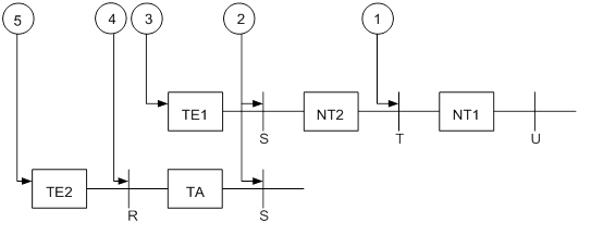
ITU-T I.411 standardizes the ISDN user-network interface and provides a reference configuration for ISDN access. As shown in Figure 2, the reference configuration contains the following elements:
· Function groups—Sets of functions required for accessing an ISDN network.
? Network terminal 1 (NT1)—Implements the functionality of the first layer in the OSI reference model, such as subscriber-line transmission, loop test, and D-channel competition.
? Network terminal 2 (NT2)—Implements the functionality of layers 1 through 3. NT2 is also known as the intelligent network terminal.
? Category-1 terminal equipment (TE1)—User equipment compliant with the ISDN interface provisions. TE1 is also known as the ISDN standard terminal. Digital phone-set is an example of TE1.
? Category-2 terminal equipment (TE2)—User equipment incompliant with the ISDN interface provisions. TE2 is also known as non-ISDN standard terminal equipment.
? Terminal adapter (TA)—Provides adaptation for TE2 to access a standard ISDN interface.
· Reference points—Points used to differentiate function groups.
? R—Reference point between a non-ISDN equipment and TA.
? S—Reference point between a user terminal and NT2.
? T—Reference point between NT1 and NT2.
? U—Reference point between NT1 and line terminal.
Figure 2 Referential ISDN user-network interface configuration
Configuration prerequisites
Before you configure an ISDN BRI interface, verify the following items:
· Interface type (ISDN BRI U or ISDN BRI S/T) provided by your telecom service provider—You must identify this information before you purchase a router. You must perform this task because the UNI implementation of a service provider might deviate from ITU-T I.411.
· Availability of digital service—The router requires digital transmission. You must subscribe to the digital call service for an ISDN line.
· Connection type (point-to-point or point-to-multipoint)—Because ISDN supports semi-permanent connections, you can use an ISDN leased line to connect two permanent points. To connect more than two points, use a point-to-multipoint connection.
· Availability of the calling line identification function—This function can filter calling numbers on an ISDN line to block unauthorized users from the router.
Configuration procedure
ISDN BRI interfaces are used for dialup purposes. For more information about dial-up configuration, see Layer 2—WAN Configuration Guide.
To configure an ISDN BRI interface:
|
Step |
Command |
Remarks |
|
1. Enter system view. |
system-view |
N/A |
|
2. Enter ISDN BRI interface view. |
interface bri number |
N/A |
|
3. (Optional.) Configure the interface description. |
description text |
By default, the description of an interface is interface-name Interface, for example, Bri2/4/0 Interface. |
|
4. (Optional.) Enable external loopback on the ISDN BRI interface. |
loopback { b1 | b2 | both | remote } |
By default, external loopback is disabled on the ISDN BRI interface. |
|
5. Set the MTU for the BRI interface. |
mtu size |
The default setting is 1500 bytes. |
|
6. Set the keepalive interval. |
timer-hold seconds |
The default setting is 10 seconds. |
|
7. Set the maximum number of keepalive attempts. |
timer-hold retry retries |
The default setting is 5. The interface determines that the remote end is down if it does not receive a keepalive response after the maximum number of keepalive attempts have been made. |
|
8. Set the intended bandwidth for the BRI interface. |
bandwidth bandwidth-value |
By default, the expected bandwidth (in kbps) is the interface baud rate divided by 1000. |
|
9. (Optional.) Restore the default settings for the BRI interface. |
default |
N/A |
|
10. (Optional.) Bring up the BRI interface. |
undo shutdown |
By default, a BRI interface is up. |
|
11. (Optional.) Activate the BRI interface. |
activate |
By default, a BRI interface is not activated. By default, a BRI interface is active only when a call is present. |
Displaying and maintaining ISDN BRI interfaces
Execute display commands in any view and reset commands in user view.
|
Task |
Command |
|
Display information about ISDN BRI interfaces. |
display interface [ bri [ interface-number ] ] [ brief [ description | down ] ] |
|
Clear statistics for ISDN BRI interfaces. |
reset counters interface [ bri [ interface-number ] ] |
Configuring a CE1/PRI interface
The following TDM systems are available in the data communications system:
· E1 system—Recommended by ITU-T and widely used in Europe and China.
· T1 system—Recommended by ANSI and widely used in North America and Japan. (Japan uses the J1 system. This system is considered to be a T1 system because of their similarity.)
A CE1/PRI interface can operate in channelized or unchannelized mode.
Channelized modes include CE1 mode and PRI mode. In CE1 or PRI mode, a CE1/PRI interface is physically divided into 32 timeslots numbered 0 to 31. Timeslot 0 is used to transmit synchronizing information.
· In CE1 mode, you can bundle all timeslots except timeslot 0 into a maximum of 31 channel sets.
For each channel set, the system automatically creates a serial interface named serial interface-number:set-number. This interface has the same logical features as a standard synchronous serial interface. The interface supports settings including:
? Data link protocols, such as PPP, HDLC, FR, or STLP.
? IP addressing.
? Interface backup settings if the interface is used as a primary or backup interface.
? NAT and packet filtering.
· In PRI mode, timeslot 16 is used as the D channel to transmit signaling. You can bundle all timeslots except timeslots 0 and 16 to form a B channel, and then bundle the B channel and timeslot 16 into a PRI set. Only one PRI set can be bundled on a CE1/PRI interface.
CE1/PRI interfaces have six physical types. The system creates different interfaces when you bundle PRI sets on CE1/PRI interfaces of different physical types, as shown in Table 1.
Table 1 Automatically created interfaces on CE1/PRI interfaces of different physical types
|
Physical type of CE1/PRI interfaces |
Automatically created interfaces for a PRI set |
|
PHY_E1 |
One serial interface (serial interface-number:15) |
|
PHY_VE1 |
· One serial interface (serial interface-number:15) · One voice interface (subscriber-line interface-number:15) |
|
PHY_DVE1 |
· One serial interface (serial interface-number:15) · One voice interface (subscriber-line interface-number:15) |
|
PHY_E1POS |
· One serial interface (serial interface-number:15) · One FCM interface (fcm interface-number:15) |
|
PHY_E1DM |
· One serial interface (serial interface-number:15) · One AM interface (analogmodem interface-number:15) |
|
PHY_E1POSDM |
· One serial interface (serial interface-number:15) · One FCM interface (fcm interface-number:15) · One AM interface (analogmodem interface-number:15) |
The created serial interface has the same logical features as an ISDN PRI interface. The interface supports settings including:
? DDR.
? PPP and PPP authentication.
? IP addressing.
? Interface backup settings if you use the interface as a primary or backup interface.
? NAT and packet filtering.
For information about configuring AM interfaces, see "Configuring an AM interface."
For information about configuring FCM interfaces, see "Configuring an FCM interface."
For information about configuring voice interfaces, see Voice Configuration Guide.
The unchannelized mode is called E1 mode. For a CE1/PRI interface in E1 mode, the system automatically creates a 2.048 Mbps serial interface named serial interface-number:0. This interface has the same logical features as a standard synchronous serial interface. The interface supports settings including:
· Data link protocols, such as PPP, HDLC, FR, or STLP.
· IP addressing.
· Interface backup settings if the interface is used as a primary or backup interface.
· NAT and packet filtering.
Configuring a CE1/PRI interface in E1 mode
|
Step |
Command |
Remarks |
|
1. Enter system view. |
system-view |
N/A |
|
2. Enter CE1/PRI interface view. |
controller e1 interface-number |
N/A |
|
3. Configure the interface to operate in E1 mode. |
using e1 |
By default, a CE1/PRI interface operates in channelized mode. |
|
4. (Optional.) Enable alarm indication signal (AIS) detection. |
detect-ais |
By default, AIS detection is disabled. |
|
5. (Optional.) Set other interface parameters. |
N/A |
Configuring a CE1/PRI interface in CE1 mode
|
Step |
Command |
Remarks |
|
1. Enter system view. |
system-view |
N/A |
|
2. Enter CE1/PRI interface view. |
controller e1 interface-number |
N/A |
|
3. Configure the interface to operate in channelized mode. |
using ce1 |
By default, a CE1/PRI interface operates in channelized mode. |
|
4. Bundle timeslots on the interface into a channel set. |
channel-set set-number timeslot-list list |
By default, no channel sets exist on a CE1/PRI interface. |
|
5. Set the framing format. |
frame-format { crc4 | no-crc4 } |
The default is no-CRC4. |
|
6. (Optional.) Enable RAI detection on the interface. |
alarm-detect rai |
By default, RAI detection is enabled on the interface. |
|
7. (Optional.) Set other interface parameters. |
N/A |
Configuring a CE1/PRI interface in PRI mode
A CE1/PRI interface can operate only in PRI mode if its physical type is PHY_E1POS, PHY_E1DM, or PHY_E1POSDM.
To configure a CE1/PRI interface in PRI mode:
|
Step |
Command |
Remarks |
|
1. Enter system view. |
system-view |
N/A |
|
2. Enter CE1/PRI interface view. |
controller e1 interface-number |
N/A |
|
3. Configure the interface to operate in channelized mode. |
using ce1 |
By default, a CE1/PRI interface operates in channelized mode. |
|
4. (Optional.) Set the interface to synchronous or asynchronous mode. |
By default, a CE1/PRI interface operates in synchronous mode. This command is available only for CE1/PRI interfaces on the DHMIM-1E1POS1DM card. These interfaces can operate only in PRI mode because their physical type is PHY_E1POSDM. |
|
|
5. Bundle timeslots on the interface into a PRI set. |
pri-set [ timeslot-list list ] |
By default, no PRI set exists on a CE1/PRI interface. |
|
6. (Optional.) Set other interface parameters. |
N/A |
Configuring other CE1/PRI interface parameters
|
Step |
Command |
Remarks |
|
1. Enter system view. |
system-view |
N/A |
|
2. Enter CE1/PRI interface view. |
controller e1 interface-number |
N/A |
|
3. Configure the interface description. |
description text |
By default, the description of an interface is interface-name Interface. |
|
4. Set the line code format. |
code { ami | hdb3 } |
The default is high density bipolar 3 (HDB3). |
|
5. Enable or disable user data inversion. |
By default, user data inversion is disabled. |
|
|
6. Set the cable type. |
cable { long | short } |
The default cable setting is long mode. |
|
7. Set the cable impedance. |
cable-type { 75 | 120 } |
By default, the cable impedance of a CE1/PRI interface is 75 ohm. This command is available only on E1T1 interface modules that operate in E1 mode. |
|
8. Set the clock mode. |
clock { master | slave } |
The default clock mode is slave, which is line clock. |
|
9. Enable automatic clock mode change. |
clock-change auto |
By default, automatic clock mode change is disabled. |
|
10. Set the line idle code type. |
Idle-code { 7e | ff } |
The default is 0x7E. |
|
11. Set the type and the number of interframe filling tags. |
itf { number number | type { 7e | ff } } |
By default: · The type of the interframe filling tag is 0x7E. · The number of interframe filling tags is four. |
|
12. Set the loopback mode. |
loopback { local | payload | remote } |
By default, loopback is disabled. |
|
13. (Optional.) Restore the default settings for the CE1/PRI interface. |
default |
N/A |
|
14. Bring up the CE1/PRI interface. |
undo shutdown |
By default, a CE1/PRI interface is up. |
|
15. Return to system view. |
quit |
N/A |
|
16. Enter the view of the synchronous serial interface. |
·
In E1 mode: ·
In CE1 mode: ·
In PRI mode: |
Make sure the synchronous serial interface is the one created for CE1/PRI interface. |
|
17. Set the CRC mode. |
crc { 16 | 32 | none } |
The default is 16-bit CRC. |
Displaying and maintaining CE1/PRI interfaces
Execute display commands in any view and reset commands in user view.
|
Task |
Command |
|
Display information about CE1/PRI interfaces. |
display controller e1 [interface-number ] |
|
Display information about a channel set or PRI set. |
display interface serial interface-number:set-number |
|
Clear statistics for CE1/PRI interfaces. |
reset counters controller e1 [ interface-number ] |
Configuring a CT1/PRI interface
A CT1/PRI interface can operate only in channelized (CT1 or PRI) mode.
In CT1 or PRI mode, a CT1/PRI interface is physically divided into 24 timeslots numbered 1 to 24.
· In CT1 mode, you can bundle all timeslots into multiple channel sets.
For each channel set, the system automatically creates a serial interface named serial interface-number:set-number. This interface has the same logical features as a standard synchronous serial interface. The interface supports settings including:
? Data link protocols, such as PPP, HDLC, FR, or STLP.
? IP addressing.
? Interface backup settings if the interface is used as a primary or backup interface.
? NAT and packet filtering.
· In PRI mode, timeslot 24 is the D channel for signaling transmission. You can bundle all other timeslots to form a B channel, and then bundle the B channel and the D channel to form a PRI set. You can create only one PRI set on a CT1/PRI interface.
For the PRI set, the system automatically creates a serial interface named serial interface-number:23. This interface has the same logical features as an ISDN PRI interface. The interface supports settings including:
? DDR.
? PPP and PPP authentication.
? IP addressing.
? Interface backup settings if the interface is used as a primary or backup interface.
? NAT and packet filtering.
Configuring a CT1/PRI interface in CT1 mode
|
Step |
Command |
Remarks |
|
1. Enter system view. |
system-view |
N/A |
|
2. Enter CT1/PRI interface view. |
controller t1 interface-number |
N/A |
|
3. Configure the interface to operate in channelized mode. |
By default, a CT1/PRI interface operates in channelized mode. |
|
|
4. Bundle timeslots on the interface into a channel set. |
channel-set set-number timeslot-list list [ speed { 56k | 64k } ] |
By default, no channel sets exist on a CT1/PRI interface. |
|
5. (Optional.) Set other interface parameters. |
N/A |
Configuring a CT1/PRI interface in PRI mode
|
Step |
Command |
Remarks |
|
1. Enter system view. |
system-view |
N/A |
|
2. Enter CT1/PRI interface view. |
controller t1 interface-number |
N/A |
|
3. Configure the interface to operate in channelized mode. |
By default, a CT1/PRI interface operates in channelized mode. |
|
|
4. Bundle timeslots on the interface into a PRI set. |
pri-set [ timeslot-list list ] |
By default, no PRI set exists on a CT1/PRI interface. |
|
5. (Optional.) Set other interface parameters. |
N/A |
Configuring other CT1/PRI interface parameters
|
Step |
Command |
Remarks |
|
1. Enter system view. |
system-view |
N/A |
|
2. Enter CT1/PRI interface view. |
controller t1 interface-number |
N/A |
|
3. Configure the interface description. |
description text |
By default, the description of an interface is interface-name Interface. |
|
4. Set the cable length and attenuation. |
cable long { 0db | -7.5db | -15db | -22.5db } cable short { 133ft | 266ft | 399ft | 533ft | 655ft } |
The long 0db keyword applies by default. |
|
5. Set the line code format. |
code { ami | b8zs } |
The default is B8ZS. |
|
6. Enable or disable user data inversion. |
data-coding { normal | inverted } |
By default, user data inversion is disabled. |
|
7. Set the clock mode. |
clock { master | slave } |
The default is slave, which is line clock. |
|
8. Set the framing format. |
frame-format { sf | esf } |
The default is ESF. |
|
9. Enable RAI detection on the interface. |
alarm-detect rai |
By default, RAI detection is enabled on the interface. This command is applicable when the framing format is ESF. |
|
10. Set the line idle code type. |
Idle-code { 7e | ff } |
The default is 0x7E. |
|
11. Set the type and the number of interframe filling tags. |
itf { number number | type { 7e | ff } } |
By default: · The type of the interframe filling tag is 0x7E. · The number of interframe filling tags is four. |
|
12. Set the number of interframe filling tags. |
itf number number |
The default is four. |
|
13. Set alarm thresholds. |
alarm-threshold { ais { level-1 | level-2 } | lfa { level-1 | level-2 | level-3 | level-4 } | los { pulse-detection | pulse-recovery } value } |
By default: · For LOS alarm, the threshold of pulse-detection is 176 and the threshold of pulse-recovery is 22. If the number of the pulses detected during the total length of 176 pulse detection intervals is smaller than 22 (the pulse-recovery threshold), a LOS alarm occurs. · Both AIS alarm threshold and LFA5 alarm threshold are level-1. |
|
14. Set the behavior of the interface on the FDL in ESF framing. |
fdl { ansi | att | both | none } |
By default, FDL is disabled. |
|
15. Enable loopback. |
loopback { local | payload | remote } |
By default, loopback is disabled. |
|
16. Send remote loopback control code. |
sendloopcode { fdl-ansi-llb-down | fdl-ansi-llb-up | fdl-ansi-plb-down | fdl-ansi-plb-up | fdl-att-plb-down | fdl-att-plb-up | inband-llb-down | inband-llb-up } |
By default, no remote loopback control code is sent. |
|
17. Restore the default settings for the CT1/PRI interface. |
default |
N/A |
|
18. (Optional.) Bring up the CT1/PRI interface. |
undo shutdown |
By default, a CT1/PRI interface is up. |
|
19. Enter the view of the synchronous serial interface. |
·
For a channel set: ·
For the PRI set: |
Make sure the synchronous serial interface is the one created for the CT1/PRI interface. |
|
20. Set the CRC mode. |
crc { 16 | 32 | none } |
The default is 16-bit CRC. |
Starting a BERT test on a CT1/PRI interface
Bit error rate test (BERT) operates as follows:
1. The local end sends out a pattern, which is looped over on the line and sent back to the local end.
2. The local end checks the received pattern for the bit error rate to help determine the line condition.
You must configure loopback to allow the transmitted pattern to loop back from a point on the line. For example, enable far-end loopback on the remote interface.
To start a BERT test on a CT1/PRI interface:
|
Step |
Command |
Remarks |
|
1. Enter system view. |
system-view |
N/A |
|
2. Enter CT1/PRI interface view. |
controller t1 interface-number |
N/A |
|
3. Start a BERT test. |
bert pattern { 2^20 | 2^15 } time minutes [ unframed ] |
By default, no BERT test is performed. |
|
4. (Optional.) Verify the state and result of the BERT test. |
display controller t1 [ interface-number ] |
N/A |
Displaying and maintaining CT1/PRI interfaces
Execute display commands in any view and reset commands in user view.
|
Task |
Command |
|
Display information about CT1/PRI interfaces. |
display controller t1 [ interface-number ] |
|
Display information about a channel set or PRI set. |
display interface serial interface-number:set-number |
|
Clear statistics for CE1/PRI interfaces. |
reset counters controller t1 [ interface-number ] |
Configuring an E1-F interface
E1-F interfaces, which are fractional E1 interfaces, are simplified CE1/PRI interfaces. They are a cost-effective alternative to CE1/PRI interfaces for E1 access services that do not require multiple channel sets or ISDN PRI.
An E1-F interface has the following features:
· In framed mode, an E1-F interface can bind timeslots into only one channel set. In contrast, a CE1/PRI interface can group and bundle timeslots randomly into multiple channel sets.
· An E1-F interface does not support PRI mode.
· An E1-F interface can operate in either framed (the default) or unframed mode.
? In unframed mode, an E1-F interface provides 2048 kbps of data bandwidth. For the interface, a synchronous serial interface is created automatically.
? In framed mode, an E1-F interface is physically divided into 32 timeslots numbered 0 through 31. Timeslot 0 is used for transmitting synchronization information. All other timeslots can randomly form one channel set. For the channel set, a synchronous serial interface is created automatically. The interface rate is n × 64 kbps, where n is the number of bundled timeslots.
· The synchronous serial interface created in either mode has the same logical features as a standard synchronous serial interface and supports the following protocols:
? Data link layer protocols, such as PPP, HDLC, STLP, and Frame Relay.
? Network layer protocols, such as IP.
You can configure this interface in the same way you configure a standard synchronous serial interface.
Configuring an E1-F interface in framed mode
|
Step |
Command |
Remarks |
|
1. Enter system view. |
system-view |
N/A |
|
2. Enter E1-F interface view. |
interface serial interface-number |
N/A |
|
3. Configure the interface to operate in framed mode. |
undo fe1 unframed |
The default is framed mode. |
|
4. Bundle timeslots on the interface. |
fe1 timeslot-list range |
By default, if no timeslot range is specified, all timeslots are bundled. |
|
5. Set the framing format. |
fe1 frame-format { crc4 | no-crc4 } |
The default is no-CRC4. |
|
6. (Optional.) Enable RAI detection on the interface. |
fe1 alarm-detect rai |
By default, RAI detection is enabled on the interface. |
|
7. (Optional.) Set other interface parameters. |
N/A |
Configuring an E1-F interface in unframed mode
|
Step |
Command |
Remarks |
|
1. Enter system view. |
system-view |
N/A |
|
2. Enter E1-F interface view. |
interface serial interface-number |
N/A |
|
3. Configure the interface to operate in unframed mode. |
fe1 unframed |
The default is framed mode. |
|
4. (Optional.) Enable AIS detection. |
fe1 detect-ais |
By default, AIS detection is disabled. |
|
5. (Optional.) Set other interface parameters. |
N/A |
Configuring other E1-F interface parameters
|
Step |
Command |
Remarks |
|
1. Enter system view. |
system-view |
N/A |
|
2. Enter E1-F interface view. |
interface serial serial-number |
N/A |
|
3. Configure the interface description. |
description text |
By default, the description of an interface is interface-name Interface. |
|
4. Set the line code format. |
fe1 code { ami | hdb3 } |
The default is HDB3. |
|
5. Enable or disable user data inversion. |
fe1 data-coding { inverted | normal } |
By default, user data inversion is disabled. |
|
6. Set the clock mode. |
fe1 clock { master | slave } |
The default is slave, which is line clock. |
|
7. Enable automatic clock mode change. |
clock-change auto |
By default, automatic clock mode change is disabled. |
|
8. Set the cable type. |
fe1 cable { long | short } |
By default, the cable type is long. |
|
9. Set the cable impedance. |
fe1 cable-type { 75 | 120 } |
By default, the cable impedance of an E1-F interface is 75 ohm. This command is available only on E1T1-F interface modules that operate in E1-F mode. |
|
10. Set the CRC mode. |
crc { 16 | 32 | none } |
The default is 16-bit CRC. |
|
11. Set the line idle code type. |
fe1 idle-code { 7e | ff } |
The default is 0x7E. |
|
12. Set the type and the number of interframe filling tags. |
fe1 itf { number number | type { 7e | ff } } |
By default: · The type of the interframe filling tag is 0x7E. · The number of interframe filling tags is four. |
|
13. Enable loopback and set the loopback mode. |
fe1 loopback { local | payload | remote } |
By default, loopback is disabled. |
|
14. Set the MTU for the BRI interface. |
mtu size |
The default setting is 1500 bytes. |
|
15. Set the keepalive interval. |
timer-hold seconds |
The default setting is 10 seconds. |
|
16. Set the maximum number of keepalive attempts. |
timer-hold retry retries |
The default setting is 5. The interface determines that the remote end is down if it does not receive a keepalive response after the maximum number of keepalive attempts have been made. |
|
17. Set the intended bandwidth for the E1-F interface. |
bandwidth bandwidth-value |
By default, the expected bandwidth (in kbps) is the interface baud rate divided by 1000. |
|
18. Restore the default settings for the E1-F interface. |
default |
N/A |
|
19. Bring up the E1-F interface. |
undo shutdown |
By default, an E1-F interface is up. |
Displaying and maintaining E1-F interfaces
Execute display commands in any view and reset commands in user view.
|
Task |
Command |
|
Display information about E1-F interfaces. |
display fe1 [ serial interface-number ] |
|
Display the status of an E1-F interface. |
display interface serial interface-number |
|
Clear statistics for E1-F interfaces. |
reset counters interface [ serial [ interface-number ] ] |
Configuring a T1-F interface
T1-F interfaces, fractional T1 interfaces, are simplified CT1/PRI interfaces. They are a cost-effective alternative to CT1/PRI interfaces for T1 access services that do not require multiple channel sets or ISDN PRI.
A T1-F interface has the following features:
· In framed mode, a T1-F interface can bind timeslots into only one channel set. In contrast, a CT1/PRI interface can group and bundle timeslots randomly into multiple channel sets.
· A T1-F interface does not support PRI mode.
A T1-F interface can only operate in framed mode. Timeslots 1 through 24 on the interface can randomly form a channel set. For the channel set, the system creates one synchronous serial interface. The interface rate is n × 64 kbps or n × 56 kbps, where n is the number of bundled timeslots. The synchronous serial interface has the same logical features as a standard synchronous serial interface and supports the following protocols:
· Data link layer protocols, such as PPP, HDLC, STLP, and Frame Relay.
· Network layer protocols, such as IP.
You can configure this interface in the same way you configure a standard synchronous serial interface.
Configuration procedure
To configure a T1-F interface:
|
Step |
Command |
Remarks |
|
1. Enter system view. |
system-view |
N/A |
|
2. Enter T1-F interface view. |
interface serial interface-number |
N/A |
|
3. (Optional.) Configure the interface description. |
description text |
By default, the description of an interface is interface-name Interface. |
|
4. Bundle timeslots on the interface into a channel set. |
ft1 timeslot-list range [ speed { 56k | 64k } ] |
By default, if no timeslot range is specified, all timeslots are bundled into one channel set. The default timeslot speed is 64 kbps, and the default T1-F interface speed is 1536 kbps. |
|
5. Set the cable length and attenuation. |
ft1 cable { long decibel | short length } |
By default, the long 0db keyword applies. |
|
6. Set the line code format. |
ft1 code { ami | b8zs } |
The default is B8ZS. |
|
7. Enable or disable user data inversion. |
ft1 data-coding { inverted | normal } |
By default, user data inversion is disabled. |
|
8. Set the clock mode. |
ft1 clock { master | slave } |
The default is slave, which is line clock. |
|
9. Set the framing format. |
ft1 frame-format { esf | sf } |
The default is esf. |
|
10. (Optional.) Enable RAI detection on the interface. |
ft1 alarm-detect rai |
By default, RAI detection is enabled on the interface. This command is applicable when the framing format is ESF. |
|
11. Set the type of line idle code. |
ft1 idle-code { 7e | ff } |
The default is 0x7E. |
|
12. Set the type and the number of interframe filling tags. |
ft1 itf { number number | type { 7e | ff } } |
By default: · The type of the interframe filling tag is 0x7E. · The number of interframe filling tags is four. |
|
13. Set the number of interframe filling tags. |
ft1 itf number number |
The default is four. |
|
14. Set alarm thresholds. |
ft1 alarm-threshold { ais { level-1 | level-2 } | lfa { level-1 | level-2 | level-3 | level-4 } | los { pulse-detection | pulse-recovery } value } |
By default: · For LOS alarm, the threshold of pulse-detection is 176 and the threshold of pulse-recovery is 22. If the number of the pulses detected during the total length of 176 pulse detection intervals is smaller than 22 (the pulse-recovery threshold), a LOS alarm occurs. · Both AIS alarm threshold and LFA alarm threshold are level-1. |
|
15. Set the behavior of the interface on the FDL in ESF framing. |
ft1 fdl { ansi | att | both | none } |
By default, FDL is disabled. |
|
16. (Optional.) Enable loopback and set the loopback mode. |
ft1 loopback { local | payload | remote } |
By default, loopback is disabled. |
|
17. (Optional.) Send remote control loopback code. |
ft1 sendloopcode { fdl-ansi-llb-down | fdl-ansi-llb-up | fdl-ansi-plb-down | fdl-ansi-plb-up | fdl-att-plb-down | fdl-att-plb-up | inband-llb-down | inband-llb-up } |
By default, no remote control code is sent. |
|
18. Set the CRC mode. |
crc { 16 | 32 | none } |
The default is 16-bit CRC. |
|
19. Set the MTU for the BRI interface. |
mtu size |
The default setting is 1500 bytes. |
|
20. Set the keepalive interval. |
timer-hold seconds |
The default setting is 10 seconds. |
|
21. Set the maximum number of keepalive attempts. |
timer-hold retry retries |
The default setting is 5. The interface determines that the remote end is down if it does not receive a keepalive response after the maximum number of keepalive attempts have been made. |
|
22. (Optional.) Set the intended bandwidth for the T1-F interface. |
bandwidth bandwidth-value |
By default, the expected bandwidth (in kbps) is the interface baud rate divided by 1000. |
|
23. (Optional.) Restore the default settings for the T1-F interface. |
default |
N/A |
|
24. Bring up the T1-F interface. |
undo shutdown |
By default, a T1-F interface is up. |
Starting a BERT test on a T1-F interface
BERT operates as follows:
1. The local end sends out a pattern, which is looped over on the line and sent back to the local end.
2. The local end checks the received pattern for the bit error rate to help determine the line condition.
You must configure loopback to allow the transmitted pattern to loop back from a point on the line. For example, enable far-end loopback on the remote interface.
To start a BERT test on a T1-F interface:
|
Step |
Command |
Remarks |
|
1. Enter system view. |
system-view |
N/A |
|
2. Enter T1-F interface view. |
interface serial interface-number |
N/A |
|
3. Start a BERT test. |
ft1 bert pattern { 2^20 | 2^15 } time minutes [ unframed ] |
By default, no BERT test is performed. |
|
4. (Optional.) Verify the state and result of the BERT test. |
display ft1 [ serial interface-number ] |
N/A |
Displaying and maintaining T1-F interfaces
Execute display commands in any view and reset commands in user view.
|
Task |
Command |
|
Display information about T1-F interfaces. |
display ft1 [ serial interface-number ] |
|
Display the status of a T1-F interface. |
display interface serial interface-number |
|
Clear statistics for T1-F interfaces. |
reset counters interface [ serial [ interface-number ] ] |
Configuring a CE3 interface
E3 belongs to the digital carrier system of ITU-T. It transmits data at 34.368 Mbps and uses HDB3 as the line code format.
A CE3 interface can operate in either E3 or CE3 (the default) mode.
· In E3 mode, a CE3 interface provides 34.368 Mbps of data bandwidth. No timeslots are divided. The system automatically creates a synchronous serial interface for it. The serial interface name uses the serial number/0:0 format.
· In CE3 mode, a CE3 interface can demultiplex 16 channels of E1 signals in compliance with ITU-T G.751 and G.742. Each E1 line can be divided into 32 timeslots numbered 0 to 31. Timeslot 0 is for framing signal transmission and does not support bundling. All other timeslots can be randomly bundled into n × 64 kbps channels, where n is the number of bundled timeslots.
A CE3 interface can be channelized into E1 lines in framed mode or unframed mode.
? If an E1 line operates in unframed (E1) mode, the system automatically creates a 2048 kbps synchronous serial interface for it. The serial interface name uses the serial number/line-number:0 format.
? If an E1 line operates in framed (CE1) mode, you can bundle timeslots on it. For each channel set, the system automatically creates a synchronous serial interface. The serial interface name uses the serial number/line-number:set-number format. The interface rate is n × 64 kbps, where n is the number of bundled timeslots.
· The synchronous serial interface created in E3 or CE3 mode has the same logical features as a standard synchronous serial interface and supports the following protocols:
? Data link layer protocols, such as PPP, HDLC, STLP, and Frame Relay.
? Network layer protocols, such as IP.
You can configure this interface in the same way you configure a standard synchronous serial interface.
Configuring a CE3 interface in E3 mode
|
Step |
Command |
Remarks |
|
1. Enter system view. |
system-view |
N/A |
|
2. Enter CE3 interface view. |
controller e3 interface-number |
N/A |
|
3. (Optional.) Configure the interface to operate in E3 mode. |
using e3 |
The default operating mode is CE3 mode. |
|
4. (Optional.) Configure the interface to operate in FE3 mode and set the DSU mode or the subrate. |
fe3 { dsu-mode { 0 | 1 } | subrate number } |
By default, DSU mode 1 (the Kentrox mode) is used, and the subrate is 34010 kbps. |
|
5. (Optional.) Configure the interface description. |
description text |
By default, the description of an interface is interface-name Interface. |
|
6. (Optional.) Configure the CE3 interface to perform BERT test. |
bert pattern { 2^7 | 2^11 | 2^15 | qrss } time number [ unframed ] |
By default, no BERT test is performed. |
|
7. (Optional.) Set the clock mode. |
clock { master | slave } |
The default mode for both the CE3 interface and E1 line is slave, which is line clock. |
|
8. (Optional.) Set the national bit. |
national-bit { 0 | 1 } |
The default is 1. |
|
9. (Optional.) Enable loopback. |
loopback { local | payload | remote } |
By default, loopback is disabled. |
|
10. (Optional.) Restore the default settings for the CE3 interface. |
default |
N/A |
|
11. (Optional.) Bring up the CE3 interface. |
undo shutdown |
By default, a CE3 interface is up. |
|
12. Return to system view. |
quit |
N/A |
|
13. Enter synchronous serial interface view. |
interface serial number/0:0 |
Make sure the synchronous serial interface is the one created for the CE3 interface. |
|
14. Set the CRC mode. |
crc { 16 | 32 | none } |
The default is 16-bit CRC. |
Configuring a CE3 interface in CE3 mode
When you change the interface state during the configuration, make sure you understand the following information:
· Shutting down or bringing up a CE3 interface also shuts down or brings up all its lines and serial interfaces, including:
? E1 lines demultiplexed from the CE3 interface.
? Serial interfaces created for unframed E1 lines.
? Serial interfaces created for channel sets on framed E1 lines.
· Shutting down or bringing up an E1 line also shuts down or brings up the serial interface created for it.
· To shut down or bring up only the serial interface for an E3, unframed E1, or framed E1 channel, use the shutdown or undo shutdown command in serial interface view.
To configure a CE3 interface in CE3 mode:
|
Step |
Command |
Remarks |
|
|
1. Enter system view. |
system-view |
N/A |
|
|
2. Enter CE3 interface view. |
controller e3 interface-number |
N/A |
|
|
3. Configure the interface to operate in CE3 mode. |
using ce3 |
The default operating mode is CE3 mode. |
|
|
4. (Optional.) Set the operating mode of an E1 line on the CE3 interface. |
·
Set the operating mode to unframed (E1): · Set the operating mode to framed (CE1) and bundle timeslots: a. (Optional.) undo e1 line-number unframed b. e1 line-number channel-set set-number timeslot-list list |
By default: · An E1 line operates in framed mode (CE1 mode). · No timeslots are bundled into channel sets. |
|
|
5. (Optional.) Configure the interface description. |
description text |
By default, the description of an interface is interface-name Interface. |
|
|
6. (Optional.) Configure the CE3 interface to perform BERT test, and configure the CE3 interface to perform BERT test on an E1 channel created on the interface. |
bert pattern { 2^7 | 2^11 | 2^15 | qrss } time number [ unframed ] e1 line-number bert pattern { 2^11 | 2^15 | 2^20 | 2^23 | qrss } time number [ unframed ] |
By default, no BERT test is performed. |
|
|
7. (Optional.) Set the clock mode. |
·
For the CE3 interface: ·
For an E1 line: |
The default mode for both the CE3 interface and E1 line is slave, which is line clock. |
|
|
8. (Optional.) Set the national bit. |
national-bit { 0 | 1 } |
The default is 1. |
|
|
9. (Optional.) Enable loopback. |
·
For the CE3 interface: ·
For an E1 line: |
By default, loopback is disabled. |
|
|
10. Set E1 framing format on an E1 line. |
e1 line-number set frame-format { crc4 | no-crc4 } |
The default is no-crc4. |
|
|
11. (Optional.) Restore the default settings for the CE3 interface. |
default |
N/A |
|
|
12. Bring up the CE3 interface or an E1 line on the interface. |
·
Bring up the CE3 interface: ·
Bring up an E1 line on the CE3 interface |
By default, all CE3 interfaces and E1 lines are up. |
|
|
13. Return to system view. |
quit |
N/A |
|
|
14. Enter synchronous serial interface view. |
·
In E1 mode: ·
In CE1 mode: |
Make sure the synchronous serial interface is the one created for the E1 line you want to configure. |
|
|
15. Set the CRC mode. |
crc { 16 | 32 | none } |
The default is 16-bit CRC. |
|
Displaying and maintaining CE3 interfaces
Execute display commands in any view and reset commands in user view.
|
Task |
Command |
|
Display CE3 interface information. |
display controller e3 [ interface-number ] |
|
Display the configuration and state of a serial interface formed on a CE3 interface. |
display interface serial interface-number |
|
Clear statistics for CE3 interfaces. |
reset counters controller e3 [ interface-number ] |
Configuring a CT3 interface
Both T3 and T1 belong to the T-carrier system promoted by ANSI. T3 uses the digital signal level DS-3 and operates at 44.736 Mbps.
CT3 interfaces support the T3 (unchannelized) mode and the CT3 (channelized) mode.
· In T3 mode, a CT3 interface provides 44.736 Mbps of data bandwidth. No timeslots are divided. The system automatically creates a synchronous serial interface for it. The serial interface name uses the serial number/0:0 format.
· In CT3 mode, a CT3 interface can be demultiplexed into 28 channels of T1 signals. Each T1 line can be divided into 24 timeslots numbered 1 through 24. Each line on a T1 interface can operate at either 64 kbps or 56 kbps.
The following are schemes available for creating different rates of T1 lines on a CT3 interface in CT3 mode:
? M × 1.536 Mbps. (M is an integer in the range of 1 to 28.)
? N × 56 kbps or N x 64 kbps. (N is an integer in the range of 1 to 256.)
A T1 line can operate in T1 or CT1 mode.
? If the T1 line operates in unframed (T1) mode, the system automatically creates a 1544 kbps serial interface for it. The serial interface name uses the serial number/line-number:0 format.
? If the T1 line operates in framed (CT1) mode, you can bundle timeslots on it. The system automatically creates a synchronous serial interface for it. The serial interface name uses the serial number/line-number:set-number format. This interface operates at n × 64 kbps or n × 56 kbps, where n is the number of bundled timeslots.
· The synchronous serial interface created in T3 or CT3 mode has the same logical features as a standard synchronous serial interface and supports the following protocols:
? Data link layer protocols, such as PPP, HDLC, STLP, and Frame Relay.
? Network layer protocols, such as IP.
You can configure this interface in the same way you configure a standard synchronous serial interface.
Configuring a CT3 interface in T3 mode
|
Step |
Command |
Remarks |
|
1. Enter system view. |
system-view |
N/A |
|
2. Enter CT3 interface view. |
controller t3 interface-number |
N/A |
|
3. Configure the interface to operate in T3 mode. |
using t3 |
The default operating mode is CT3 mode. |
|
4. (Optional.) Configure the interface to operate in the FT3 mode and set the DSU mode or the subrate, or enable payload scrambling for the interface. |
ft3 { dsu-mode { 0 | 1 | 2 | 3 | 4 } | subrate number | scramble } |
By default: · DSU mode 0 (the digital link mode) is used. · The subrate is 44210 kbps. · Payload scrambling is disabled. |
|
5. (Optional.) Configure the interface description. |
description text |
By default, the description of an interface is interface-name Interface. |
|
6. Set the clock mode. |
clock { master | slave } |
The default clock mode for the CT3 interface is slave, which is line clock. |
|
7. Set the cable length. |
cable feet |
The default is 14.9 meters (49 feet). |
|
8. Set the framing format for the CT3 interface. |
frame-format { c-bit | m23 } |
By default, the framing format on the CT3 interface is C-bit. |
|
9. (Optional.) Set the loopback mode. |
loopback { local | payload | remote } |
By default, loopback is disabled. |
|
10. (Optional.) Configure alarm signal detection/sending. |
alarm { detect | generate { ais | febe | idle | rai } } |
By default, alarm signal detection is enabled and alarm signal sending is disabled. |
|
11. (Optional.) Start a BERT test. |
bert pattern { 2^7 | 2^11 | 2^15 | qrss } time number [ unframed ] |
By default, BERT test is disabled. |
|
12. (Optional.) Configure FEAC channel signal detection/sending on the CT3 interface. |
· feac detect · feac generate loopback { ds3-line | ds3-payload } · feac generate { ds3-los | ds3-ais | ds3-oof | ds3-idle | ds3-eqptfail } |
By default, FEAC channel signal detection is enabled, but no FEAC signals are sent. |
|
13. (Optional.) Configure MDL message detection/sending on the CT3 interface. |
mdl { data { eic string | fic string | | gen-no string | lic string | pfi string | port-no string | unit string } | detect | generate { idle-signal | path | test-signal } } |
By default, MDL message detection and sending are disabled and the default MDL message information applies. |
|
14. (Optional.) Restore the default settings for the CT3 interface. |
default |
N/A |
|
15. (Optional.) Bring up the CT3 interface. |
undo shutdown |
By default, a CT3 interface is up. |
|
16. Return to system view. |
quit |
N/A |
|
17. Enter synchronous serial interface view. |
interface serial number/0:0 |
Make sure the synchronous serial interface is the one created for the CT3 interface. |
|
18. Set the CRC mode. |
crc { 16 | 32 | none } |
The default is 16-bit CRC. |
Configuring a CT3 interface in CT3 mode
When you change the interface state during the configuration, make sure you understand the following information:
· Shutting down or bringing up a CT3 interface also shuts down or brings up all its lines and serial interfaces, including:
? T1 lines demultiplexed from the CT3 interface.
? Serial interfaces created for unframed T1 lines.
? The serial interfaces created for channel sets on framed T1 lines.
· Shutting down or bringing up a T1 line also shuts down or brings up the serial interface created for it.
· To shut down or bring up only the serial interface for a T3, unframed T1, or framed T1 channel, use the shutdown or undo shutdown command in serial interface view.
To configure a CT3 interface in CE3 mode:
|
Step |
Command |
Remarks |
|
1. Enter system view. |
system-view |
N/A |
|
2. Enter CT3 interface view. |
controller t3 interface-number |
N/A |
|
3. Configure the interface to operate in CT3 mode. |
using ct3 |
The default operating mode is CT3 mode. |
|
4. Set the operating mode of a T1 line on the CT3 interface. |
·
Set the operating mode to unframed (T1): · Set the operating mode to framed (CT1) and bundle timeslots: a. (Optional.) undo t1 line-number unframed b. t1 line-number channel-set set-number timeslot-list range [ speed { 56k | 64k } ] |
By default: · A T1 line operates in framed (CT1) mode. · No timeslots are bundled into channel sets. |
|
5. (Optional.) Configure the interface description. |
description text |
By default, the description of an interface is interface-name Interface. |
|
6. (Optional.) Set the clock mode. |
·
Set the clock mode for a CT3 interface: ·
Set the clock mode for a T1 line on the CT3
interface: |
The default clock mode for the CT3 interface is slave. The default clock mode for the T1 line is slave. |
|
7. Set the cable length. |
cable feet |
The default is 14.9 meters (49 feet). |
|
8. Set the framing format for the CT3 interface. |
frame-format { c-bit | m23 } |
By default, the framing format on the CT3 interface is C-bit. |
|
9. Set the framing format for the T1 line. |
t1 line-number set frame-format { esf | sf } |
By default, the framing format on the T1 line is ESF. |
|
10. (Optional.) Set the loopback mode. |
·
On the CT3 interface: ·
On a T1 line: |
By default, loopback is disabled. |
|
11. (Optional.) Configure alarm signal detection/sending. |
·
On the CT3 interface: ·
On a T1 line: |
By default, alarm signal detection is enabled and alarm signal sending is disabled. |
|
12. (Optional.) Start a BERT test. |
·
On the CT3 interface: ·
On a T1 line: |
By default, BERT test is disabled. |
|
13. (Optional.) Configure FEAC channel signal detection/sending on the CT3 interface. |
· feac detect · feac generate loopback { ds3-line | ds3-payload } · feac generate { ds3-los | ds3-ais | ds3-oof | ds3-idle | ds3-eqptfail } |
By default, FEAC channel signal detection is enabled, but no FEAC signals are sent. |
|
14. (Optional.) Configure MDL message detection/sending on the CT3 interface. |
mdl { data { eic string | fic string | | gen-no string | lic string | pfi string | port-no string | unit string } | detect | generate { idle-signal | path | test-signal } } |
By default, MDL message detection and sending are disabled and the default MDL message information applies. |
|
15. (Optional.) Place a T1 line on the far-end CT3 interface in a loopback. |
t1 line-number sendloopcode { fdl-ansi-line-up | fdl-ansi-payload-up | fdl-att-payload-up | inband-line-up } |
By default, no loopback mode is set. |
|
16. (Optional.) Set the FDL format for a T1 channel. |
t1 line-number set fdl { ansi | att | both | none } |
By default, FDL is disabled. This operation applies only to T1 channels that are formed on CT3 interfaces, operate in channelized mode, and use ESF as the T1 framing format. |
|
17. (Optional.) Restore the default settings for the CT3 interface. |
default |
N/A |
|
18. (Optional.) Bring up the CT3 interface or a T1 line on the interface. |
·
Bring up the CT3 interface: ·
Bring up a T1 line on the CT3 interface: |
By default, all CT3 interfaces and T1 lines are up. |
|
19. Return to system view. |
quit |
N/A |
|
20. Enter synchronous serial interface view. |
·
In T1 mode: ·
In CT1 mode: |
Make sure the synchronous serial interface is the one created for the T1 line you want to configure. |
|
21. Set the CRC mode. |
crc { 16 | 32 | none } |
The default is 16-bit CRC. |
Displaying and maintaining CT3 interfaces
Execute display commands in any view and reset commands in user view.
|
Task |
Command |
|
Display CT3 interface information. |
display controller t3 [ interface-number ] [ t1 line-number ] |
|
Display the configuration and state of a serial interface formed on a CT3 interface. |
display interface serial interface-number |
|
Display the state of a T1 line. |
t1 line-number show |
|
Clear statistics for CT3 interfaces. |
reset counters controller t3 [ interface-number ] |
Configuring POS interfaces
This chapter describes how to configure physical parameters for POS interfaces, including standard POS interfaces and POS subinterfaces.
Before you configure the link and network layer parameters on a POS interface, you must perform the tasks in this chapter to configure its physical parameters.
This feature is supported only on devices with related interfaces. For information about interfaces on the device, see the installation guide and the interface module guide.
Overview
Packet over SONET/SDH (POS) is a technology widely used on WAN and MAN. It supports data packets such as IP packets.
SONET and SDH
Synchronous Optical Network (SONET) adopts optical transmission. It is a synchronous transmission system defined by the ANSI and is an international standard transmission protocol.
ITU-T Synchronous Digital Hierarchy (SDH) uses a SONET rate subset. SDH adopts synchronous multiplexing and a flexible mapping structure. It can add or drop low-speed tributary signals to or from SDH signals without a large number of multiplexing/demultiplexing devices. This reduces signal attenuation and decreases device investments.
POS
POS maps length-variable packets directly to SONET synchronous payloads and uses the SONET physical layer transmission standard. It offers high-speed, reliable, and point-to-point data connectivity.
The POS interfaces on the device support PPP, Frame Relay, and HDLC at the data link layer and IP at the network layer. Depending on the device model, the transmission rate of POS interfaces can be STM-1, STM-4, and STM-16. The rate of a level is four times the nearest lower level.
Configuring a standard POS interface
|
Step |
Command |
Remarks |
|
1. Enter system view. |
system-view |
N/A |
|
2. Configure the packet statistics collection interval. |
flow-interval interval |
The default setting is 300 seconds. The setting in system view takes effect on all interfaces. |
|
3. Enter standard POS interface view. |
interface pos interface-number |
N/A |
|
4. (Optional.) Configure the interface description. |
description text |
By default, the description of a POS interface is interface name Interface, for example, Pos2/2/1 Interface. |
|
5. Set the keepalive interval. |
timer-hold seconds |
The default setting is 10 seconds. |
|
6. Set the maximum number of keepalive attempts. |
timer-hold retry retries |
The default setting is 5. The interface determines that the remote end is down if it does not receive a keepalive response after the maximum number of keepalive attempts have been made. |
|
7. Set the clock mode. |
clock { master | slave } |
The default setting is slave. |
|
8. Set the CRC length. |
crc { 16 | 32 } |
The default setting is 32 bits. |
|
9. (Optional.) Set the loopback mode. |
loopback { local | remote } |
By default, loopback is disabled. |
|
10. Configure the overhead bytes. |
·
Configure the C2 path signal label
byte: ·
Configure the J0 regenerator section
trace byte: ·
Configure the J1 path trace byte: |
By default: · The C2 byte is 0x16. · The system uses the SDH framing format. · In SDH frames, both J0 and J1 bytes are empty strings. |
|
11. Set the framing format. |
frame-format { sdh | sonet } |
The default setting is SDH. |
|
12. (Optional.) Enable payload scrambling. |
scramble |
By default, payload scrambling is enabled. |
|
13. Set the data link layer protocol. |
link-protocol { fr | hdlc | ppp } |
The default setting is PPP. |
|
14. Set the MTU. |
mtu size |
The default setting is 1500 bytes. |
|
15. (Optional.) Enable interface dampening on the interface. |
dampening [ half-life reuse suppress max-suppress-time ] |
By default, interface dampening is disabled on POS interfaces. |
|
16. Configure the expected bandwidth of the interface. |
bandwidth bandwidth-value |
By default, the expected bandwidth (in kbps) is the interface baud rate divided by 1000. |
|
17. (Optional.) Restore the default settings for the POS interface. |
default |
N/A |
|
18. Shut down and bring up the interface. |
shutdown undo shutdown |
By default, a standard POS interface is up. For the settings to take effect, you must perform this step. If no cable is connected to the interface, shut down the interface to prevent interface exceptions. |
Configuring a POS subinterface
|
Step |
Command |
Remarks |
|
1. Enter system view. |
system-view |
N/A |
|
2. Create a POS subinterface and enter its view. |
interface pos interface-number.subnumber [ p2mp | p2p ] |
You can create POS subinterfaces only on Frame Relay-enabled standard POS interfaces. |
|
3. Configure the subinterface description. |
description text |
By default, the description of a POS subinterface is interface name Interface, for example, Pos2/2/1.1 Interface. |
|
4. Set the MTU. |
mtu size |
The default setting is 1500 bytes. |
|
5. Configure the expected bandwidth of the subinterface. |
bandwidth bandwidth-value |
By default, the expected bandwidth (in kbps) is the interface baud rate divided by 1000. |
|
6. Restore the default settings for the POS subinterface. |
default |
N/A |
|
7. Shut down and bring up the POS subinterface. |
shutdown undo shutdown |
By default, a POS subinterface is up. For the settings to take effect, you must perform this step. |
Configuring B1/B2/B3 alarms for standard POS interfaces
B1, B2, and B3 bytes indicate the signal transmission performance of a line at different levels.
· B1 alarm occurs if the bite error rate of a complete STM-N frame exceeds the B1 alarm threshold.
· B2 alarm occurs if the bite error rate of an STM-1 frame exceeds the B2 alarm threshold.
· B3 alarm occurs if the bite error rate of a multiplexed signal (VC3 or VC4 frame) in the STM-1 frame exceeds the B3 alarm threshold.
To generate SNMP notifications about these alarms, you must set the alarm thresholds and enable the notifications.
For more information about SNMP notifications, see Network Management and Monitoring Configuration Guide.
To configure the B1, B2, or B3 alarm for a standard POS interface:
|
Step |
Command |
Remarks |
|
1. Enter system view. |
system-view |
N/A |
|
2. Enter standard POS interface view. |
interface pos interface-number |
N/A |
|
3. Enable the SNMP notification about the B1, B2, or B3 alarm. |
snmp-agent trap enable { b1-tca | b2-tca | b3-tca } |
By default, SNMP notifications about B1, B2, and B3 alarms are enabled on a standard POS interface. |
Displaying and maintaining POS interfaces
Execute display commands in any view and reset commands in user view.
|
Command |
|
|
Display information about POS interfaces. |
display interface [ pos [ interface-number | interface-number.subnumber ] ] [ brief [ description | down ] ] |
|
Clear statistics for POS interfaces. |
reset counters interface [ pos [ interface-number | interface-number.subnumber ] ] |
POS interface configuration examples
Directly connecting routers through POS interfaces
Network requirements
As shown in Figure 3, connect the routers through POS interfaces.
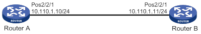
Configuration procedure
1. Configure POS 2/2/1 on Router A:
# Assign an IP address to the interface.
<RouterA> system-view
[RouterA] interface pos 2/2/1
[RouterA-Pos2/2/1] ip address 10.110.1.10 255.255.255.0
# Configure the data link layer protocol of the interface.
[RouterA-Pos2/2/1] link-protocol ppp
# Set the MTU to 1500 bytes for the interface.
[RouterA-Pos2/2/1] mtu 1500
# Shut down, and then bring up the interface for the settings to take effect.
[RouterA-Pos2/2/1] shutdown
[RouterA-Pos2/2/1] undo shutdown
2. Configure POS 2/2/1 on Router B:
# Set the clock mode to master on the interface.
<RouterB> system-view
[RouterB] interface pos 2/2/1
[RouterB-Pos2/2/1] clock master
# Assign an IP address to the interface.
[RouterB-Pos2/2/1] ip address 10.110.1.11 255.255.255.0
# Configure the data link layer protocol of the interface.
[RouterB-Pos2/2/1] link-protocol ppp
# Set the MTU to 1500 bytes for the interface.
[RouterB-Pos2/2/1] mtu 1500
# Shut down, and then bring up the interface for the settings to take effect.
[RouterB-Pos2/2/1] shutdown
[RouterB-Pos2/2/1] undo shutdown
Verifying the configuration
# Verify the POS interface settings, for example, on Router A.
<RouterA> display interface pos
# Verify that Router A and Router B can ping each other at the POS interfaces. (Details not shown.)
Connecting routers through POS interfaces across a Frame Relay network
Network requirements
As shown in Figure 4, use POS subinterfaces to connect Router A to Router B and Router C across a Frame Relay network. The routers are all DTEs on the Frame Relay network.
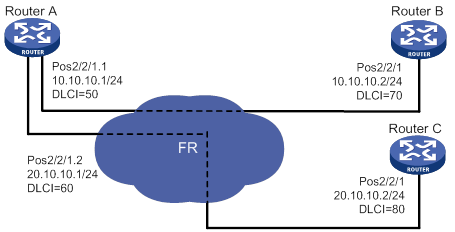
Configuration procedure
1. Configure Router A:
# Set the clock mode to slave on POS 2/2/1.
<RouterA> system-view
[RouterA] interface pos 2/2/1
[RouterA-Pos2/2/1] clock slave
# Enable Frame Relay on POS 2/2/1.
[RouterA-Pos2/2/1] link-protocol fr
# Configure POS 2/2/1 as DTE.
[RouterA-Pos2/2/1] fr interface-type dte
[RouterA-Pos2/2/1] quit
# Create subinterface 1 on POS 2/2/1 and assign an IP address to it.
[RouterA] interface pos 2/2/1.1
[RouterA-Pos2/2/1.1] ip address 10.10.10.1 255.255.255.0
# Assign a virtual circuit with DLCI 50 to subinterface 1.
[RouterA-Pos2/2/1.1] fr dlci 50
[RouterA-Pos2/2/1.1-fr-dlci-50] quit
# Map DLCI 50 to the peer IP address 10.10.10.2.
[RouterA-Pos2/2/1.1] fr map ip 10.10.10.2 50
# Set the MTU to 1500 for subinterface 1.
[RouterA-Pos2/2/1.1] mtu 1500
[RouterA-Pos2/2/1.1] quit
# Create subinterface 2 on POS 2/2/1 and assign an IP address to it.
[RouterA] interface pos 2/2/1.2
[RouterA-Pos2/2/1.2] ip address 20.10.10.1 255.255.255.0
# Assign a virtual circuit with DLCI 60 to subinterface 2.
[RouterA-Pos2/2/1.2] fr dlci 60
[RouterA-Pos2/2/1.2-fr-dlci-60] quit
# Map DLCI 60 to the peer IP address 20.10.10.2.
[RouterA-Pos2/2/1.2] fr map ip 20.10.10.2 60
# Set the MTU to 1500 for subinterface 2.
[RouterA-Pos2/2/1.2] mtu 1500
[RouterA-Pos2/2/1.2] quit
2. Configure Router B:
# Set the clock mode to slave on POS 2/2/1.
[RouterB] interface pos 2/2/1
[RouterB-Pos2/2/1] clock slave
# Enable Frame Relay on POS 2/2/1.
[RouterB-Pos2/2/1] link-protocol fr
# Configure POS 2/2/1 as DTE.
[RouterB-Pos2/2/1] fr interface-type dte
# Assign an IP address to POS 2/2/1.
[RouterB-Pos2/2/1] ip address 10.10.10.2 255.255.255.0
# Assign a virtual circuit with DLCI 70 to POS 2/2/1.
[RouterB-Pos2/2/1] fr dlci 70
[RouterB-Pos2/2/1-fr-dlci-70] quit
# Map DLCI 70 to the peer IP address 10.10.10.1.
[RouterB-Pos2/2/1] fr map ip 10.10.10.1 70
# Set the MTU to 1500 for POS 2/2/1.
[RouterB-Pos2/2/1] mtu 1500
3. Configure Router C in the same way Router B is configured. (Details not shown.)
Verifying the configuration
# Verify the POS interface settings.
<RouterA> display interface pos
# Verify that Router A and Router B can ping each other. (Details not shown.)
# Verify that Router A and Router C can ping each other. (Details not shown.)
Troubleshooting POS interfaces
Interface physically down
Symptom
The physical state of the POS interface is down.
Solution
To resolve the problem:
· Verify that the POS interface is connected correctly to the remote port.
? The transmit connector at one end must be connected to the receive connector at the other end.
? The transmit and receive connectors of the POS interface are not connected by the same fiber. If they are connected by the same fiber, the display interface command displays the "loopback detected" message, whether or not the loopback detection feature is enabled.
· If the two POS interfaces are directly connected, verify that the two ends use different clock mode settings.
· If the problem persists, contact H3C Support.
Data link layer down
Symptom
The physical layer is up, but the data link layer is down.
Solution
To resolve the problem:
· Verify that the two ends have matching clock mode, scrambling setting, and physical parameters.
· Verify that the two ends have the same data link layer protocol.
· If the problem persists, contact H3C Support.
Packet loss
Symptom
A large number of IP packets are dropped.
Solution
To resolve the problem:
· Verify that the correct clock mode is configured on the POS interface.
Incorrect clock mode setting can incur a large number of CRC errors.
· Verify that the two ends have the same MTU setting.
· If the problem persists, contact H3C Support.
Configuring CPOS interfaces
Overview
The low-speed tributary signals multiplexed to form an SDH signal are called channels. The channelized POS (CPOS) interface makes full use of SDH to provide the following benefits:
· Provides precise bandwidth division.
· Reduces the number of low-speed physical interfaces on devices.
· Enhances aggregation capacity.
· Improves the access capacity of leased lines.
This feature is supported only on devices with related interfaces. For information about interfaces on the device, see the installation guide and the interface module guide.
CPOS interfaces
The device supports the CPOS interfaces in Table 2.
|
Interface type |
Channelization/multiplexing capabilities |
|
CPOS E1 |
63 E1 channels (E1 channel configurable). |
|
CPOS T1 |
84 T1 channels (T1 channel configurable). |
Overhead bytes
SDH provides layered precise monitoring and management.
SDH monitoring functions are implemented using overhead bytes. SDH provides monitoring at section and channel levels.
· Sections are subdivided into regenerator and multiplex sections.
· Channels are subdivided into higher-order and lower-order paths.
SDH provides a variety of overhead bytes, but only those involved in CPOS configuration are discussed in this section.
SOH
The section overhead (SOH) is further classified into the regenerator section overhead (RSOH) and the multiplex section overhead (MSOH).
The J0 regenerator section trace byte is included in RSOH to repeatedly send the section access point identifier. The receiver uses this identifier to make sure it is in continuous connection with the sender. This byte can be any character in the network of the same carrier. If the networks of two carriers are involved, the sending and receiving devices at network borders must use the same J0 byte. With the J0 byte, carriers can detect and troubleshoot faults in advance or use less time to recover networks.
POH
The payload of an STM-N frame includes the path overhead (POH), which monitors low-speed tributary signals.
The SOH monitors the section layer, and the POH monitors the path layer. The POH is divided into the higher-order path overhead and the lower-order path overhead.
Higher-order path overhead monitors paths at the VC-4/VC-3 level.
Similar to the J0 byte, the higher-order VC-N path trace byte J1 is included in the higher-order path overhead to repeatedly send the higher-order path access point identifier. The receiving end of the path uses this identifier to make sure it is in continuous connection with the specified sender. The sender and the receiver must use the same J1 byte.
In addition, the path signal label byte C2 is included in the higher-order path overhead to indicate the multiplexing structure of VC frames and the properties of payload, including the following:
· Whether the path is carrying traffic.
· What type of traffic is carried.
· How the VC frames are mapped.
The sender and receiver must use the same C2 byte.
CPOS interface application scenarios
CPOS E1/T1 interfaces are typically used to aggregate E1 and T1 lines, as shown in Figure 5.
In actual applications, the connection between low-end devices and the CPOS interfaces might span more than one transmission network and might require relay. This is similar to the scenario where low-end devices are connected to a high-end device through one or multiple leased lines.
Figure 5 CPOS E1/T1 interface application scenario
CPOS interface configuration task list
|
Configure a CPOS E1 interface: · (Required.) Configuring the operating mode of an interface module · (Required.) Configuring basic functions of a CPOS interface · (Required.) Configuring an E1 channel |
|
Configure a CPOS T1 interface: · (Required.) Configuring the operating mode of an interface module · (Required.) Configuring basic functions of a CPOS interface · (Required.) Configuring a T1 channel |
Configuring the operating mode of an interface module
The CPOS interface modules can operate in different modes to provide different types of interfaces. You must make sure a CPOS interface module is operating in the desired mode before you configure the interfaces on it. For more information about interface module mode configuration, see device management in Fundamentals Configuration Guide.
Configuring basic functions of a CPOS interface
|
Step |
Command |
Remarks |
|
1. Enter system view. |
system-view |
N/A |
|
2. Enter CPOS interface view. |
controller cpos cpos-number |
N/A |
|
3. (Optional.) Configure the interface description. |
description text |
By default, the description of a CPOS interface is interface name Interface, for example, Cpos2/2/1 Interface. |
|
4. Set the framing format. |
frame-format { sdh | sonet } |
The default setting is SDH. |
|
5. Set the clock mode. |
clock { master | slave } |
The default setting is slave. |
|
6. (Optional.) Set the loopback mode. |
loopback { local | remote } |
By default, loopback is disabled. |
|
7. Set the AUG multiplexing mode. |
multiplex mode { au-3 | au-4 } |
The default setting is AU-4. The command is available only in SDH framing. |
|
8. Configure the SOH and higher-order path overhead bytes. |
flag { c2 path-number c2-value | s1 s1-value | s1s0 path-number s1s0-value } flag { j0 | j1 path-number } { sdh | sonet } flag-value |
By default: · c2 is 0x02. · s1 is 0x0f. · s1s0 is 0x00 for SONET and 0x02 for SDH. · j0 is 0x01 for SONET and a 16-byte empty character string for SDH. · j1 is a 64-byte empty character string for SONET and a 16-byte empty character string for SDH. |
|
9. Set the signal degrade (SD) or signal fail (SF) alarm threshold for the interface. |
threshold { sd sdvalue | sf sfvalue } * |
The default SD and SF alarm thresholds are 10e–6 and 10e–3, respectively. |
|
10. (Optional.) Restore the default settings for the CPOS interface. |
default |
N/A |
|
11. Bring up the CPOS interface. |
undo shutdown |
By default, a CPOS interface is up. If no cable is connected to a physical interface, shut down the interface with the shutdown command to prevent problems. |
Configuring an E1 channel
The serial interfaces created for E1 channels have the same logical features as a synchronous serial interface. You can configure these serial interfaces in the same way you configure a standard synchronous serial interface. For more information about configuring synchronous serial interfaces, see "Configuring WAN interfaces."
To configure an E1 channel:
|
Step |
Command |
Remarks |
|
1. Enter system view. |
system-view |
N/A |
|
2. Enter CPOS interface view. |
controller cpos cpos-number |
N/A |
|
3. Set the framing format for the E1 channel. |
e1 e1-number frame-format { crc4 | no-crc4 } |
The default setting is no-CRC4. |
|
4. Set the clock mode for the E1 channel. |
e1 e1-number clock { master | slave } |
The default setting is slave. |
|
5. (Optional.) Enable loopback on the E1 channel. |
e1 e1-number loopback { local | payload | remote } |
By default, loopback is disabled. |
|
6. Set overhead bytes for the E1 channel. |
e1 e1-number flag c2 c2-value e1 e1-number flag j2 { sdh | sonet } j2-string |
By default, C2 is set to hexadecimal 02, and J2 contains cyclic empty character strings. |
|
7. (Optional.) Set the E1 channel alignment mode. |
channel-align-mode { alcatel | lucent } |
N/A |
|
8. Configure the E1 channel operating mode. |
·
Specify the unframed mode: · Specify the framed mode and bundle timeslots: a. (Optional.) undo e1 e1-number unframed b. e1 e1-number channel-set set-number timeslot-list range |
By default, an E1 channel operates in framed mode and is not channelized. When you place an E1 channel in unframed mode, the system automatically creates a 2.048 Mbps serial interface. When you bundle timeslots on an E1 channel in framed mode, the system automatically creates a serial interface for the bundle. The rate of the serial interface is identical to 64 kbps x number of bundled timeslots. |
|
9. (Optional.) Shut down the specified E1 channel. |
e1 e1-number shutdown |
By default, an E1 channel is up. |
Configuring a T1 channel
The serial interface created for T1 channels have the same logical features as a synchronous serial interface. You can configure these serial interfaces in the same way you configure a standard synchronous serial interface. For more information about configuring synchronous serial interfaces, see "Configuring WAN interfaces."
To configure a T1 channel:
|
Step |
Command |
Remarks |
|
1. Enter system view. |
system-view |
N/A |
|
2. Enter CPOS interface view. |
controller cpos cpos-number |
N/A |
|
3. Set the framing format for the T1 channel. |
t1 t1-number frame-format { esf | sf } |
The default setting is ESF. |
|
4. Set the clock mode for the T1 channel. |
t1 t1-number clock { master | slave } |
The default setting is slave. |
|
5. (Optional.) Enable loopback on the T1 channel. |
t1 t1-number loopback { local | payload | remote } |
By default, loopback is disabled. |
|
6. Set overhead bytes for the T1 channel. |
t1 t1-number flag c2 c2-value t1 t1-number flag j2 { sdh | sonet } j2-string |
By default, C2 is set to hexadecimal 02, and J2 contains cyclic empty character strings. |
|
7. Configure the T1 operating mode. |
·
Specify the unframed mode: · Specify the framed mode and bundle timeslots: a. (Optional.) undo t1 t1-number unframed b. t1 t1-number channel-set set-number timeslot-list range [ speed { 56k | 64k } ] |
By default, a T1 channel operates in framed mode and is not channelized. When you place a T1 channel in unframed mode, the system automatically creates a 1.544 Mbps serial interface. When you bundle timeslots on a T1 channel, the system automatically creates a serial interface for the bundle. The rate of the serial interface is identical to timeslot rate (54 kbps or 64 kbps) x number of bundled timeslots. |
|
8. (Optional.) Shut down the specified T1 channel. |
t1 t1-number shutdown |
By default, a T1 channel is up. |
Displaying and maintaining CPOS interfaces
Execute display commands in any view and reset commands in user view.
|
Task |
Command |
|
Display CPOS interface status information. |
display controller cpos [ cpos-number ] |
|
Display status information for an E1 channel on a CPOS interface. |
display controller cpos cpos-number e1 e1-number |
|
Display status information for a T1 channel on a CPOS interface. |
display controller cpos cpos-number t1 t1-number |
|
Display information about an E1/T1 serial interface. |
display interface serial interface-number/channel-number:set-number |
|
Clear statistics for a CPOS interface. |
reset counters controller cpos interface-number |
For more information about the display interface serial command, see Interface Command Reference.
CPOS-E1 interface configuration example
Network requirements
As shown in Figure 6, branch nodes Router B through Router H are uplinked to the central node Router A through E1 links. Router A aggregates these E1 links by using a CPOS interface.
Add one additional E1 link on Router B to expand its capacity, and use an MP-group interface to bind the two E1 links.
Configuration procedure
|
|
IMPORTANT: For correct network synchronization, make sure the master clock mode is configured on the SONET/SDH devices connected to the routers. |
1. Configure Router A:
# Configure E1 channels 1 and 2 of CPOS 2/2/1 to operate in unframed mode.
<RouterA> system-view
[RouterA] controller cpos 2/2/1
[RouterA-Cpos2/2/1] e1 1 unframed
[RouterA-Cpos2/2/1] e1 2 unframed
# Create interface MP-group 2/0/0 and assign an IP address to it.
[RouterA] interface mp-group 2/2/0
[RouterA-Mp-group2/0/0] ip address 10.1.1.1 24
[RouterA-Mp-group2/0/0] quit
# Assign Serial 2/2/1/1:0 to interface MP-group 2/0/0.
[RouterA] interface serial2/2/1/1:0
[RouterA-Serial2/2/1/1:0] ppp mp mp-group 2/0/0
[RouterA-Serial2/2/1/1:0] quit
# Assign Serial 2/2/1/2:0 to interface MP-group 2/0/0.
[RouterA] interface serial2/2/1/2:0
[RouterA-Serial2/2/1/2:0] ppp mp mp-group 2/0/0
[RouterA-Serial2/2/1/2:0] quit
2. Configure Router B:
# Configure E1 2/4/1 to operate in E1 mode.
<RouterB> system-view
[RouterB] controller e1 2/4/1
[RouterB-E1 2/4/1] using e1
[RouterB-E1 2/4/1] quit
# Configure E1 2/4/2 to operate in E1 mode.
[RouterB] controller e1 2/4/2
[RouterB-E1 2/4/2] using e1
[RouterB-E1 2/4/2] quit
# Create interface MP-group 2/0/0 and assign an IP address to it.
[RouterB] interface mp-group 2/0/0
[RouterB-Mp-group2/0/0] ip address 10.1.1.2 24
[RouterB-Mp-group2/0/0] quit
# Assign Serial 2/4/1:0 to interface MP-group 2/0/0.
[RouterB] interface serial2/4/1:0
[RouterB-Serial2/4/1:0] ppp mp mp-group 2/0/0
[RouterB-Serial2/4/1:0] quit
# Assign Serial 2/4/2:0 to interface MP-group 2/0/0.
[RouterB] interface serial2/4/2:0
[RouterB-Serial2/4/2:0] ppp mp mp-group 2/0/0
[RouterB-Serial2/4/2:0] quit
Verifying the configuration
# Verify the serial interface configuration and state, for example, on Router B.
<RouterB> display interface serial 2/4/1:0
# Verify the MP interface, and MP bundle configuration and state, for example, on Router B.
<RouterB> display interface mp-group 2/0/0
<RouterB> display interface display ppp mp
# Verify that the routers can ping one another. (Details not shown.)
Troubleshooting CPOS interfaces
Loop and link layer protocol down state detected on serial interfaces created for E1 channels on the CPOS interface
Symptom
The H3C router is connected to another vendor's router through E1 channels on CPOS interfaces across an SDH network. PPP is used on the serial interface created for the E1 channel set.
The output from the display interface serial command shows the following errors:
· The physical state of the serial interface is up, but the link protocol is down.
· The serial interface is in a looped condition.
Solution
The symptom might occur when the router and its directly connected SDH device have different multiplex paths for the E1 channels. Multiplex path inconsistency can cause PPP negotiation failure because the SDH device transmits signals from the router in incorrect timeslots to the remote end. If the SDH device incorrectly maps a signal to an idle timeslot in a looped condition, the router can detect a loop on the serial interface.
To resolve the problem:
1. Identify the multiplex path for the E1 channels on the router.
<H3C> display controller cpos e1
2. Verify that the router and its directly connected SDH device have the same multiplex path for E1 channels. (Details not shown.)
3. Debug the loop condition.
<H3C> debugging ppp lcp error
4. If the problem persists, contact H3C Support.
Configuring ATM interfaces
Overview
This feature is supported only on devices with related interfaces. For information about interfaces on the device, see the installation guide and the interface module guide.
ATM and DSL
Asynchronous Transfer Mode (ATM) is a technology based on packet transmission mode and incorporates the high-speed of circuit transmission mode. It is a backbone network technology for transmission of audio, video, and data. Because of its flexibility and support for multimedia services, ATM is regarded as a core technology for implementing broadband communications.
Digital Subscriber Line (DSL) is a technology providing high-speed data transmission over copper wires. It includes the following technologies:
· Asymmetric Digital Subscriber Line (ADSL).
· High-bit-rate Digital Subscriber Line (HDSL).
· Very High-rate Digital Subscriber Line (VDSL).
· Single-pair high-speed DSL defined in ITU-T Standard G.991.2 (G.SHDSL).
· Symmetric Digital Subscriber Line (SDSL).
These DSL technologies are different in signal transmission speed and distance and link rate symmetric mode (determined by the uplink and downlink rates).
The ATM physical layer is at the bottom of the ATM reference model. It primarily delivers valid cells and the associated timing signals between the upper layer and transmission medium. The speeds of physical access media are defined in international standards such as ATM OC-3c/STM-1. Most DSL applications are ATM-based, combining the advantages of ATM with the low transmission cost feature of DSL. DSL technologies have been widely adopted for broadband access.
ATM interface types
The device supports the following ATM interface types:
· ATM OC-3c/STM-1 based on SONET/SDH.
· ATM ADSL based on ADSL technology.
· ATM G.SHDSL based on G.SHDSL technology.
These interfaces support IPoA, IPoEoA, PPPoA, and PPPoEoA. For more information, see Layer 2—WAN Configuration Guide.
ATM interface features
ATM interfaces support the following features:
· Variable Bit Rate-Real Time (VBR-RT).
· Variable Bit Rate-Non Real Time (VBR-NRT).
· Permanent Virtual Circuit (PVC).
· Traffic Shaping based on Virtual Circuit (VC).
· User-to-Network Interface (UNI).
· RFC1483, Multiprotocol Encapsulation over ATM Adaptation Layer 5.
· RFC 2225, Classical IP and ARP over ATM.
· RFC 2390, Inverse Address Resolution Protocol.
· ATM Adaptation Layer 5 (AAL5).
Feature and hardware compatibility
This feature is supported on routers installed with ATM-OC3, ADSL2+, G.SHDSL, or G.SHDSL.BIS interface modules.
Configuring an ATM OC-3c/STM-1 interface
ATM OC-3c/STM-1 is a physical transmission medium for ATM interfaces. Its transmission rate is 155 Mbps. This section covers only the physical configurations of the ATM OC-3c/STM-1 interface. For information about configuring ATM services, see Layer 2—WAN Configuration Guide.
To configure an ATM OC-3c/STM-1 interface:
|
Step |
Command |
Remarks |
|
system-view |
N/A |
|
|
interface atm interface-number |
N/A |
|
|
description text |
By default, the description is interface-name Interface, such as ATM 3/2/1 Interface. |
|
|
clock { master | slave } |
||
|
5. Configure the frame format for the interface. |
frame-format { sdh | sonet } |
By default, the frame format is SDH. |
|
scramble |
||
|
7. Configure overhead bytes for the interface. |
flag c2 flag-value |
The default value for c2 is 0x13. |
|
flag { j0 | j1 } { sdh | sonet } flag-value |
By default, the system adopts the SDH frame format. The default values for both j0 and j1 are null. |
|
|
8. (Optional.) Enable loopback on the interface and set the loopback mode. |
loopback { cell | local | remote } |
|
|
bandwidth bandwidth-value |
By default, the expected bandwidth (in kbps) is calculated by using the following formula: Interface baud rate/1000. |
|
|
10. Configure an MTU value for the interface. |
mtu size |
|
|
11. (Optional.) Restore the default of the interface. |
default |
N/A |
|
12. Bring up the interface. |
undo shutdown |
Configuring an ADSL interface
Overview
ADSL is an asymmetric transmission technology that implements high-speed data transmission over twisted-pair copper wire. It uses unused high frequency ranges in the regular telephone line with a different modulation method. With standard ADSL, the band from 26 kHz to 138 kHz is used for upstream communication, and 138 kHz to 1.104 MHz is used for downstream communication. The upstream rate is up to 640 kbps, and the downstream rate is up to 8 Mbps.
Some ADSL technologies, however, can provide faster transmission rates by using the following methods:
· Improving modulation rate, coding gain, and initialization state machine.
· Reducing frame head overhead.
· Using enhanced signal processing methods.
ADSL2 can provide the upstream transmission rate up to 1024 kbps and downstream transmission rate up to 12 Mbps. By expanding the downstream band from 1.104 MHz to 2.208 MHz, ADSL2+ can provide an upstream transmission rate up to 2048 kbps and a downstream rate up to 24 Mbps.
The transmission rate of ADSL is susceptible to the transmission distance and line quality. An increased transmission distance means decreased line quality and transmission rate. A decreased transmission distance means increased line quality and transmission rate. When setting up a link, ADSL can automatically tune the rate by considering actual line conditions such as distance and noise.
Two types of ADSL modules/cards are available:
· ADSL over POTS—ADSL over the telephone line. Both telephone calls and ADSL access are implemented on the telephone line.
· ADSL over ISDN—ADSL over the ISDN line. Both ISDN access and ADSL access are implemented on the ISDN line. ADSL signals are transmitted at high frequency ranges, and ISDN signals are transmitted at low frequency ranges.
For a typical network topology for routers with ADSL interfaces, see Figure 7. Both telephone calls and ADSL access are implemented on the telephone line.
|
|
IMPORTANT: When you connect ADSL interfaces, use standard twisted pairs and correctly connect the cables. |
This section covers only the physical configurations of ATM ADSL 2+ interfaces. For information about configuring ATM services, see Layer 2—WAN Configuration Guide.
Configuration procedure
To configure an ATM ADSL 2+ interface:
|
Step |
Command |
Remarks |
|
1. Enter system view. |
system-view |
N/A |
|
2. Enter ATM ADSL 2+ interface view. |
interface atm interface-number |
N/A |
|
description text |
By default, the description is interface-name Interface, such as ATM2/4/0 Interface. |
|
|
4. Activate the interface. |
activate |
By default, the interface is activated. |
|
5. Configure the standard for the ATM ADSL 2+ interface. |
adsl standard { auto | g9923 | g9925 | gdmt | glite | t1413 } |
By default, the standard for an ATM ADSL 2+ interface is auto-negotiation. |
|
6. Configure the transmit power attenuation for the ATM ADSL 2+ interface. |
adsl tx-attenuation attenuation |
By default, the transmit power attenuation is 0, which means no attenuation. |
|
bandwidth bandwidth-value |
By default, the expected bandwidth (in kbps) is calculated by using the following formula: Interface baud rate/1000. |
|
|
mtu size |
||
|
default |
||
|
10. Bring up the interface. |
undo shutdown |
Configuring a G.SHDSL interface
Overview
G.SHDSL is a symmetric transmission technology that implements high-speed data transmission over the twisted-pair copper wire by using unused high frequency ranges with a different modulation method.
Based on the maximum wire pairs supported on an interface, the G.SHDSL interfaces include the following types:
· ATM SHDSL_4WIRE—Four-wire G.SHDSL.
· ATM SHDSL_8WIRE_BIS—Eight-wire G.SHDSL.BIS.
G.SHDSL.BIS incorporates the functions of G.SHDSL, supports four wire pairs, and enhances the maximum single-pair negotiation rate from 2312 kbps to 5696 kbps.
On an interface supporting multiple wire pairs, you can configure the number of wire pairs based on the interface rate.
The transmission speed of G.SHDSL is susceptible to transmission distance and line quality. An increased transmission distance means decreased line quality and transmission rate. Decreased transmission distance means increased line quality and transmission rate. When setting up a link, G. SHDSL can automatically tune the speed taking into consideration the actual line conditions such as distance and noise.
For a typical network topology for routers with G.SHDSL interfaces, see Figure 7. Unlike ADSL, G.SHDSL does not use the splitter.
This section covers only the physical configurations of the G.SHDSL interface. For information about configuring ATM services, see Layer 2—WAN Configuration Guide.
Configuration procedure
To configure a G.SHDSL interface:
|
Step |
Command |
Remarks |
|
system-view |
||
|
2. Enter G.SHDSL interface view. |
interface atm interface-number |
N/A |
|
3. (Optional.) Configure the interface description. |
description text |
By default, the description is interface-name Interface, such as ATM 3/2/1 Interface. |
|
4. Activate the interface. |
activate |
By default, the interface is activated. |
|
shdsl annex { a | b } |
||
|
·
Configure the connection mode for
four-wire G.SHDSL interfaces: ·
Configure the connection mode for
eight-wire G.SHDSL.BIS interface: |
· A four-wire G.SHDSL interface operates in four-wire enhanced mode. · An eight-wire G.SHDSL.BIS interface operates in eight-wire mode. |
|
|
7. Configure operating mode for the interface. |
shdsl mode { co | cpe } |
|
|
8. Configure the single-pair interface rate for the interface. |
shdsl rate { rate | auto } |
· For eight-wire G.SHDSL.BIS interfaces, the single-pair interface rate is automatically negotiated. · For four-wire G.SHDSL interfaces, the single-pair interface rate is automatically negotiated in two-wire mode. It is 2312 kbps in non-two-wire modes (the four-wire interface rate is 4624 kbps). |
|
shdsl snr-margin [ current current-margin-value ] [ snext snext-margin-value ] |
By default, current-margin-value is 2 and snext-margin-value is 0. |
|
|
10. Configure the power spectral density (PSD) mode for the interface. |
shdsl psd { asymmetry | symmetry } |
|
|
shdsl pbo { value | auto } |
By default, the interface automatically tunes its transmit power. |
|
|
shdsl capability { auto | g-shdsl | g-shdsl-bis } |
· auto is adopted in CPE mode. · g-shdsl-bis is adopted in CO mode. |
|
|
13. Configure pulse amplitude modulation (PAM) constellation. |
shdsl pam { 16 | 32 | auto } |
|
|
shdsl line-probing enable |
By default, SHDSL line probing is enabled. |
|
|
bandwidth bandwidth-value |
||
|
mtu size |
||
|
17. (Optional.) Restore the default of the interface. |
default |
N/A |
|
18. Bring up the interface. |
undo shutdown |
By default, the interface is up. As a best practice, shut down the unused G.SHDSL interfaces to save system resources. |
Configuring an ATM subinterface
An ATM subinterface supports the same network layer functions as an ATM interface. The network layers of different ATM subinterfaces are independent of each other. You can configure different Layer 3 services for ATM subinterfaces, such as IP services and MPLS services. To enable an ATM interface to support multiple Layer 3 services, create multiple subinterfaces for the interface.
The rate of an ATM subinterface depends on the rates of the PVCs or PVC-groups configured on the subinterfaces. For more information, see Layer 2—WAN Configuration Guide.
To configure an ATM subinterface:
|
Step |
Command |
Remarks |
|
1. Enter system view. |
system-view |
N/A |
|
2. Create an ATM subinterface and enter its view. |
interface atm interface-number.subnumber [ p2mp | p2p ] |
By default, no ATM subinterfaces exist. |
|
description text |
||
|
4. Configure the expected bandwidth for the subinterface. |
bandwidth bandwidth-value |
By default, the expected bandwidth (in kbps) is the interface baud rate divided by 1,000. |
|
5. Configure an MTU value for the subinterface. |
mtu size |
By default, the MTU value for the subinterface is 1,500 bytes. |
|
6. Restore the default of the subinterface. |
default |
N/A |
|
7. Bring up the subinterface. |
undo shutdown |
By default, the subinterface is up. |
Configuring an EFM interface
Ethernet First Mile (EFM) interfaces receive and transmit Ethernet frames over ATM physical links and use the Ethernet protocol suite. They can transmit Ethernet frames over legacy DSL lines and achieve all-Ethernet access. By implementing stable, high-speed Ethernet packet transmission over telephone lines, EFM extends the transmission distance of Ethernet from 100 meters to 1500 meters. With EFM interfaces, the Ethernet technologies can be deployed on the access networks of telecom users, which improves network performance and lowers device and operation costs.
The device supports only EFM SHDSL_8WIRE_BIS interfaces (eight-wire G.SHDSL.BIS interfaces).
No dedicated but multi-purpose EFM cards are available. Switch the operating mode of an interface card as needed. For more information about the operating modes of an interface card, see Fundamentals Configuration Guide.
This section covers only the physical configurations of the EFM interface. You can also configure ARP, DHCP, IP address, and firewall on an EFM interface.
To configure an EFM interface:
|
Step |
Command |
Remarks |
|
1. Enter system view. |
system-view |
N/A |
|
2. Enter EFM interface view. |
interface efm interface-number |
N/A |
|
description text |
By default, the description is interface-name Interface, such as ATM 3/2/1 Interface. |
|
|
4. Configure the annex standard for the interface. |
shdsl annex { a | b } |
By default, Annex b is adopted. |
|
shdsl wire { 2 | 4-enhanced | 4-standard | 6 | 8 | auto } |
By default, an eight-wire G.SHDSL.BIS interface operates in eight-wire mode. |
|
|
6. Configure the operating mode for the interface. |
shdsl mode { co | cpe } |
By default, the operating mode of the interface is CPE. |
|
7. Configure the single-pair interface rate for the interface. |
shdsl rate { rate | auto } |
By default, the single-pair interface rate for eight-wire G.SHDSL.BIS interfaces is automatically negotiated. |
|
8. Configure the target margin to SNR. |
shdsl snr-margin [ current current-margin-value ] [ snext snext-margin-value ] |
By default, current-margin-value is 2 and snext-margin-value is 0. |
|
9. Configure the PSD mode for the interface. |
shdsl psd { asymmetry | symmetry } |
By default, the PSD mode of the interface is symmetric. |
|
10. Tune the transmit power. |
shdsl pbo { value | auto } |
By default, the interface automatically tunes its transmit power. |
|
11. Configure the PAM constellation. |
shdsl pam { 16 | 32 | auto } |
By default, the interface automatically selects its PAM. |
|
12. (Optional.) Enable SHDSL line probing. |
shdsl line-probing enable |
By default, SHDSL line probing is enabled. |
|
bandwidth bandwidth-value |
By default, the expected bandwidth (in kbps) is calculated by using the following formula: Interface baud rate/1000. |
|
|
mtu size |
By default, the MTU value for the interface is 1500 bytes. |
|
|
15. (Optional.) Restore the default of the interface. |
default |
N/A |
|
16. Bring up the interface. |
undo shutdown |
By default, the interface is up. |
Configuring an EFM subinterface
|
Step |
Command |
Remarks |
|
1. Enter system view. |
system-view |
N/A |
|
2. Create an EFM subinterface and enter its view. |
interface efm interface-number.subnumber |
By default, no EFM subinterfaces exist. |
|
description text |
||
|
4. Configure the expected bandwidth for the subinterface. |
bandwidth bandwidth-value |
By default, the expected bandwidth (in kbps) is calculated by using the following formula: Interface baud rate/1000. |
|
mtu size |
By default, the MTU value for the subinterface is 1500 bytes. |
|
|
6. Restore the default of the interface. |
default |
N/A |
|
7. Bring up the subinterface. |
undo shutdown |
Displaying and maintaining ATM interfaces
Execute display commands in any view and reset commands in user view.
|
Task |
Command |
|
Display ATM interface information. |
display interface [ atm [ interface-number ] ] [ brief [ description | down ] ] |
|
Display EFM interface information. |
display interface [ efm [ interface-number ] ] [ brief [ description | down ] ] |
|
Display DSL configuration information. |
display dsl configuration interface { atm | efm } interface-number |
|
Display DSL status information. |
display dsl status interface { atm | efm } interface-number |
|
Display DSL version information and available capabilities. |
display dsl version interface { atm | efm } interface-number |
|
Display interface traffic statistics. |
display counters { inbound | outbound } interface [ atm [ interface-number ] ] |
|
Display traffic rate statistics for interfaces in up state for the most recent statistics interval. |
display counters rate { inbound | outbound } interface [ atm [ interface-number ] ] |
|
Clear the statistics for an ATM interface. |
reset counters interface [ atm [ interface-number ] ] |
|
Clear the statistics for an EFM interface. |
reset counters interface [ efm [ interface-number ] ] |
Troubleshooting ATM interfaces
Interface state error
Symptom
The ATM interface state is down.
Solution
Verify that the Rx and Tx ends of the optical fiber are correctly connected.
If the two routers are connected back-to-back, verify that the clock mode is set to master on one interface, and to slave on the other interface. The default clock mode is slave. To set the clock mode to master, use the clock master command.
Frequent packet dropping, CRC check errors, and interface state errors
Symptom
Two routers connecting back-to-back can ping each other successfully. Frequent packet dropping and CRC errors occur, and the interface state jumps between up and down.
Solution
Verify that the ATM interfaces of the two sides are of the same type, for example, multimode fiber interfaces or single-mode fiber interfaces. If a multimode fiber interface and a single-mode fiber interface are directly connected, they can communicate in most cases. However, frequent packet dropping, CRC errors, and interface state errors might occur.
Troubleshooting DSL interfaces
Improper line operation is one of the faults that you might encounter in DSL applications. Such a fault is likely to occur on whichever devices or nodes in the hierarchical broadband network architecture. It is likely caused by the CPE device, copper wire, splitter, DSL port on DSLAM, or the broadband access server.
On the CPE, follow these steps to troubleshoot the problem:
1. Read the LEDs for the DSL interface card.
When the DSL line is training, the LINK LED blinks. After the activation succeeds, the LINK LED which should otherwise be OFF lights and stays ON. The Activity LED blinks when data is being transmitted on the line.
|
|
NOTE: Different DSL interface cards have different LEDs. |
2. Display the DSL state information by using the display dsl status command.
3. Use the debugging physical command to view details about activation, such as issuing of the activate command, activation timeout, training process, and activation success.
4. If line activation attempts always fail, verify that the line is connected securely and functioning correctly.
5. If the bit error rate is high or interference occurs too often, shut down and then bring up the interface by using the shutdown and undo shutdown commands. You can also reboot the device and reconnect the line. If the problem persists, perform an overall line condition and environment check.
Configuring loopback, null, and inloopback interfaces
This chapter describes how to configure a loopback interface, a null interface, and an inloopback interface.
Configuring a loopback interface
A loopback interface is a virtual interface. The physical layer state of a loopback interface is always up unless the loopback interface is manually shut down. Because of this benefit, loopback interfaces are widely used in the following scenarios:
· Configuring a loopback interface address as the source address of the IP packets that the device generates—Because loopback interface addresses are stable unicast addresses, they are usually used as device identifications.
? When you configure a rule on an authentication or security server to permit or deny packets that a device generates, you can simplify the rule by configuring it to permit or deny packets carrying the loopback interface address that identifies the device.
? When you use a loopback interface address as the source address of IP packets, make sure the route from the loopback interface to the peer is reachable by performing routing configuration. All data packets sent to the loopback interface are considered packets sent to the device itself, so the device does not forward these packets.
· Using a loopback interface in dynamic routing protocols—With no router ID configured for a dynamic routing protocol, the system selects the highest loopback interface IP address as the router ID. In BGP, to avoid interruption of BGP sessions due to physical port failure, you can use a loopback interface as the source interface of BGP packets.
To configure a loopback interface:
|
Step |
Command |
Remarks |
|
1. Enter system view. |
system-view |
N/A |
|
2. Create a loopback interface and enter loopback interface view. |
interface loopback interface-number |
N/A |
|
3. Set the interface description. |
description text |
The default setting is interface name Interface (for example, LoopBack1 Interface). |
|
4. Configure the expected bandwidth of the loopback interface. |
bandwidth bandwidth-value |
By default, the expected bandwidth of a loopback interface is 0 kbps. |
|
5. Restore the default settings for the loopback interface. |
default |
N/A |
|
6. Bring up the loopback interface. |
undo shutdown |
By default, a loopback interface is up. |
Configuring a null interface
A null interface is a virtual interface and is always up, but you cannot use it to forward data packets or configure it with an IP address or link layer protocol. The null interface provides a simpler way to filter packets than ACL. You can filter undesired traffic by transmitting it to a null interface instead of applying an ACL. For example, if you specify a null interface as the next hop of a static route to a network segment, any packets routed to the network segment are dropped.
To configure a null interface:
|
Step |
Command |
Remarks |
|
1. Enter system view. |
system-view |
N/A |
|
2. Enter null interface view. |
interface null 0 |
Interface Null 0 is the default null interface on the device and cannot be manually created or removed. Only one null interface, Null 0, is supported on the device. The null interface number is always 0. |
|
3. Set the interface description. |
description text |
The default setting is NULL0 Interface. |
|
4. Restore the default settings for the null interface. |
default |
N/A |
Configuring an inloopback interface
An inloopback interface is a virtual interface created by the system, which cannot be configured or deleted. The physical layer and link layer protocol states of an inloopback interface are always up. All IP packets sent to an inloopback interface are considered packets sent to the device itself and are not forwarded.
Displaying and maintaining loopback, null, and inloopback interfaces
Execute display commands in any view and reset commands in user view.
|
Task |
Command |
|
Display information about the specified or all loopback interfaces. |
display interface loopback [ interface-number ] [ brief [ description | down ] ] |
|
Display information about the null interface. |
display interface null [ 0 ] [ brief [ description | down ] ] |
|
Display information about the inloopback interface. |
display interface inloopback [ 0 ] [ brief [ description | down ] ] |
|
Clear the statistics on the specified or all loopback interfaces. |
reset counters interface loopback [ interface-number ] |
|
Clear the statistics on the null interface. |
reset counters interface null [ 0 ] |
Command and hardware compatibility,3
Configuration procedure,1
Configuration restrictions and guidelines,1
Configuring a CE1/PRI interface,23
Configuring a CE3 interface,35
Configuring a CT1/PRI interface,27
Configuring a CT3 interface,39
Configuring a G.SHDSL interface,63
Configuring a Layer 2 Ethernet interface,10
Configuring a Layer 3 Ethernet interface or subinterface,11
Configuring a loopback interface,69
Configuring a null interface,69
Configuring a POS subinterface,45
Configuring a serial interface,14
Configuring a standard POS interface,44
Configuring a T1 channel,54
Configuring a T1-F interface,33
Configuring an ADSL interface,61
Configuring an AM interface,18
Configuring an ATM OC-3c/STM-1 interface,60
Configuring an ATM subinterface,65
Configuring an E1 channel,54
Configuring an E1-F interface,30
Configuring an EFM interface,65
Configuring an EFM subinterface,66
Configuring an FCM interface,20
Configuring an inloopback interface,70
Configuring an ISDN BRI interface,21
Configuring B1/B2/B3 alarms for standard POS interfaces,46
Configuring basic functions of a CPOS interface,53
Configuring common Ethernet interface settings,3
Configuring the operating mode of an interface module,53
CPOS interface configuration task list,52
CPOS-E1 interface configuration example,56
Displaying and maintaining an Ethernet interface,12
Displaying and maintaining ATM interfaces,67
Displaying and maintaining bulk interface configuration,2
Displaying and maintaining CPOS interfaces,55
Displaying and maintaining loopback, null, and inloopback interfaces,70
Displaying and maintaining POS interfaces,46
Overview,44
Overview,51
Overview,59
POS interface configuration examples,47
Troubleshooting ATM interfaces,67
Troubleshooting CPOS interfaces,57
Troubleshooting POS interfaces,49