- Table of Contents
- Related Documents
-
| Title | Size | Download |
|---|---|---|
| 01-Text | 6.46 MB |
Examining the installation site
Installing the switch in a 19-inch rack
Rack-mounting by using front mounting brackets
Rack-mounting by using front and rear mounting brackets
Rack-mounting by using front mounting brackets and mounting rail assemblies
Mounting the switch on a workbench
Grounding the switch with a grounding strip
Grounding the switch with a grounding conductor buried in the earth ground
Installing/removing a fan tray
Installing/removing a power module
Installing a PSR150 power module
Removing a PSR150 power module
Installing a PSR360-56A/PSR720-56A/PSR1110-56A power module
Removing a PSR360-56A/PSR720-56A/PSR1110-56A power module
Connecting the AC power cord for the fixed AC power module
Connecting a DC power cord for the fixed DC power module
Connecting the AC power cord for a PSR150-A1 power module
Connecting the DC power cord for a PSR150-D1 power module
Connecting the AC power cord for a PSR360-56A, PSR720-56A, or PSR1110-56A power module
Installing/removing an expansion card
Accessing the switch for the first time
Setting up the configuration environment
Connecting the Mini USB console cable
Planning IRF fabric size and the installation site
Identifying the master switch and planning IRF member IDs
Planning IRF topology and connections
Identifying physical IRF ports on the member switches
Configuring basic IRF settings
Connecting the physical IRF ports
Verifying the IRF fabric setup
Maintenance and troubleshooting
Hot swappable power module failure
Hot swappable fan tray failure
Configuration terminal display problems
Appendix A Chassis views and technical specifications
Appendix B FRUs and compatibility matrixes
FRUs and compatibility matrixes
Connecting cables to the copper ports on the interface cards
10/100/1000BASE-T autosensing Ethernet port
1/10BASE-T autosensing Ethernet port
10/100/1000BASE-T autosensing Ethernet port LED
Port status LED on the expansion card
Input status LED and output status LED on the power module
Fan tray status LED on the fan tray
Preparing for installation
H3C S5130-HI Switch Series includes the following models:
· S5130-30S-HI
· S5130-54S-HI
· S5130-30F-HI
· S5130-30C-HI
· S5130-30C-PWR-HI
· S5130-34C-HI
· S5130-54C-HI
· S5130-54C-PWR-HI
· S5130-54QS-HI
Safety recommendations
To avoid any equipment damage or bodily injury caused by improper use, read the following safety recommendations before installation. Note that the recommendations do not cover every possible hazardous condition.
· Before cleaning the switch, remove all power cords from the switch. Do not clean the switch with a wet cloth or liquid.
· Do not place the switch near water or in a damp environment. Prevent water or moisture from entering the switch chassis.
· Do not place the switch on an unstable case or desk. The switch might be severely damaged in case of a fall.
· Ensure good ventilation of the equipment room and keep the air inlet and outlet vents of the switch free of obstruction.
· Connect the yellow-green protection grounding cable before power-on.
· Make sure the operating voltage is in the required range.
· To avoid electrical shocks, do not open the chassis while the switch is operating or when the switch is just powered off.
· When replacing field replaceable units (FRUs), including expansion cards, power modules, and fan trays, wear an ESD wrist strap to avoid damaging the units.
Examining the installation site
The switch must be used indoors. You can mount your switch in a rack or on a workbench, but make sure:
· Adequate clearance is reserved at the air inlet and outlet vents for ventilation.
· The rack or workbench has a good ventilation system.
· Identify the hot aisle and cold aisle at the installation site, and make sure ambient air flows into the switch from the cold aisle and exhausts to the hot aisle.
· Identify the airflow designs of neighboring devices, and prevent hot air flowing out of the neighboring device from entering the device.
· The rack is sturdy enough to support the switch and its accessories.
· The rack or workbench is reliably grounded.
To ensure correct operation and long service life of your switch, install it in an environment that meets the requirements described in the following subsections.
Temperature/humidity
Maintain temperature and humidity in the equipment room as described in "Appendix A Chassis views and technical specifications."
· Lasting high relative humidity can cause poor insulation, electricity leakage, mechanical property change of materials, and metal corrosion.
· Lasting low relative humidity can cause washer contraction and ESD and bring problems including loose mounting screws and circuit failure.
· High temperature can accelerate the aging of insulation materials and significantly lower the reliability and lifespan of the switch.
For the temperature and humidity requirements of different switch models, see "Technical specifications."
Cleanliness
Dust buildup on the chassis might result in electrostatic adsorption, which causes poor contact of metal components and contact points, especially when indoor relative humidity is low. In the worst case, electrostatic adsorption can cause communication failure.
Table 1 Dust concentration limit in the equipment room
|
Substance |
Concentration limit (particles/m³) |
|
Dust |
≤ 3 x 10⁴ (no visible dust on the tabletop over three days) |
|
NOTE: Dust diameter ≥ 5 μm |
|
The equipment room must also meet strict limits on salts, acids, and sulfides to eliminate corrosion and premature aging of components, as shown in Table 2.
Table 2 Harmful gas limits in the equipment room
|
Gas |
Maximum concentration (mg/m3) |
|
SO2 |
0.2 |
|
H2S |
0.006 |
|
NH3 |
0.05 |
|
Cl2 |
0.01 |
EMI
All electromagnetic interference (EMI) sources, from outside or inside of the switch and application system, adversely affect the switch in the following ways:
· A conduction pattern of capacitance coupling.
· Inductance coupling.
· Electromagnetic wave radiation.
· Common impedance (including the grounding system) coupling.
To prevent EMI, use the following guidelines:
· If AC power is used, use a single-phase three-wire power receptacle with protection earth (PE) to filter interference from the power grid.
· Keep the switch far away from radio transmitting stations, radar stations, and high-frequency devices.
· Use electromagnetic shielding, for example, shielded interface cables, when necessary.
· To prevent signal ports from getting damaged by overvoltage or overcurrent caused by lightning strikes, route interface cables only indoors.
Laser safety
|
|
WARNING! The switch is Class 1 laser device. Do not stare into any fiber port when the switch has power. The laser light emitted from the optical fiber might hurt your eyes. |
Installation tools
· Flat-blade screwdriver
· Phillips screwdriver
· ESD wrist strap
All these installation tools are user supplied.
Installing the switch
|
|
CAUTION: Keep the tamper-proof seal on a mounting screw on the chassis cover intact, and if you want to open the chassis, contact H3C for permission. Otherwise, H3C shall not be liable for any consequence. |
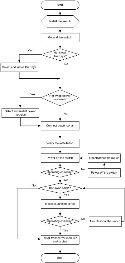
Figure 1 Hardware installation flow
Installing the switch in a 19-inch rack
Installation methods
Table 3 Installation methods for the S5130-HI switches
|
Chassis |
Installation methods |
Installation requirements |
Installation procedure |
|
S5130-30S-HI S5130-54S-HI S5130-30F-HI S5130-30C-HI S5130-34C-HI S5130-54C-HI |
Using front mounting brackets |
Install the front mounting brackets at the port side or power module side. |
|
|
S5130-30C-PWR-HI S5130-54C-PWR-HI |
Using front and rear mounting brackets |
· Install the front mounting brackets at the port side or power module side. · Install the rear mounting brackets according to the rack depth. ¡ If the rack depth is in the range of 429 to 595 mm (16.89 to 23.43 in), orient the bracket with the wide flange inside the rack. ¡ If the rack depth is in the range of 274 to 440 mm (10.79 to 17.32 in) and the distance from the rear rack posts to the inner surface of the cabinet door is longer than 153 mm (6.02 in), orient the bracket with the wide flange outside the rack. |
See "Rack-mounting by using front and rear mounting brackets." |
|
S5130-54QS-HI |
Using front mounting brackets |
Install the front mounting brackets at the power module side. |
|
|
Using front and rear mounting brackets |
· Install the front mounting brackets at the port side or power module side. · Install the rear mounting brackets according to the rack depth. ¡ If the rack depth is in the range of 332 to 496 mm (13.07 to 19.53 in), orient the bracket with the wide flange inside the rack. ¡ If the rack depth is in the range of 174 to 341 mm (6.85 to 13.43 in) and the distance from the rear rack posts to the inner surface of the cabinet door is longer than 153 mm (6.02 in), orient the bracket with the wide flange outside the rack. As a best practice, use this method for enterprise networks. |
See "Rack-mounting by using front and rear mounting brackets." |
|
|
Using front mounting brackets and mounting rail assemblies |
Install the front mounting brackets at the port side or power module side. The distance between the front rack post and the rear rack post must be in the range of 562 to 754 mm (22.13 to 29.69 in). As a best practice, use this method for data centers. |
See "Rack-mounting by using front mounting brackets and mounting rail assemblies." |
Figure 2 Rack-mounting procedure (1)
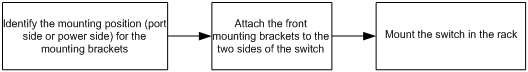
Figure 3 Rack-mounting procedure (2)
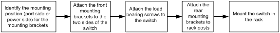
Figure 4 Rack-mounting procedure (3)

|
|
NOTE: If a rack shelf is available, you can put the switch on the rack shelf, slide the switch to an appropriate location, and attach the switch to the rack by using the mounting brackets. |
Installation accessories
Table 4 Installation accessories for the S5130-HI switches
|
Installation accessories |
S5130-30S-HI S5130-54S-HI S5130-30F-HI S5130-30C-HI S5130-34C-HI S5130-54C-HI |
S5130-30C-PWR-HI S5130-54C-PWR-HI |
S5130-54QS-HI |
|
Front mounting brackets (Figure 5) |
Provided |
Provided |
Provided |
|
Rear mounting brackets and shoulder screws (Figure 6) |
N/A |
Provided |
Provided |
|
Chassis rails and slide rails (Figure 7) |
N/A |
N/A |
Optional |
|
Grounding cable |
Provided |
Provided |
Provided |
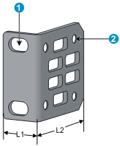
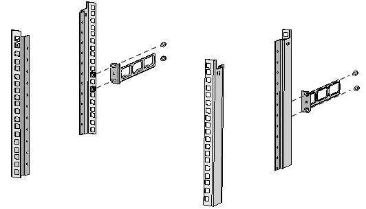
Figure 5 Front mounting bracket
|
(1) Hole for attaching the bracket to a rack |
(2) Hole for attaching the bracket to the switch chassis |
Figure 6 Rear mounting bracket and shoulder screw

|
(1) Hole for attaching the bracket to a rack |
(2) Shoulder screw |
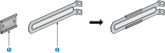
Figure 7 Rack mounting rail kit
|
(1) Chassis rail |
(2) Slide rail |
Rack-mounting by using front mounting brackets
This task requires two people.
This mounting method is applicable only to the S5130-30S-HI, S5130-54S-HI, S5130-30F-HI, S5130-30C-HI, S5130-34C-HI, S5130-54C-HI, and S5130-54QS-HI switches.
To install the switch in a 19-inch rack by using the front mounting brackets:
1. Wear an ESD wrist strap and make sure it makes good skin contact and is reliably grounded.
2. Determine the mounting position on the switch for the front mounting brackets.
You can install the front mounting brackets at one of the following positions:
¡ S5130-30S-HI, S5130-54S-HI, S5130-30F-HI, S5130-30C-HI, S5130-34C-HI, and S5130-54C-HI switches—Port side or power module side installation position.
¡ S5130-54QS-HI switch—Power module side installation position.
3. Attach the front mounting brackets to the chassis:
a. Unpack the front mounting brackets and the M4 screws (supplied with the switch) for attaching the brackets to the switch chassis.
b. Align the round holes in the wide flange of one front mounting bracket with the screw holes in the chassis.
c. Use M4 screws to attach the mounting bracket to the chassis.
d. Repeat the proceeding two steps to attach the other mounting bracket to the chassis.
Figure 8 Attaching the front mounting bracket to the port side
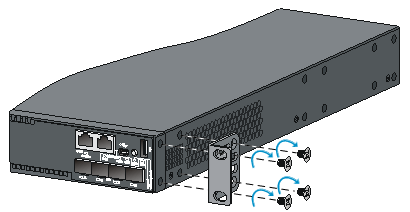
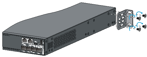
Figure 9 Attaching the front mounting bracket to the power module side
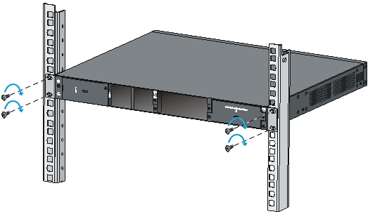
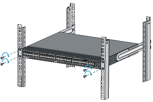
4. Mount the chassis in the rack:
a. Install cage nuts (user-supplied) in the mounting holes in the front rack posts. Make sure the corresponding cage nuts on the left and right front rack posts are at the same height.
b. One person holds the switch chassis and aligns the installation holes on the mounting brackets with the cage nuts on the rack posts.
c. The other person uses M6 screws (user supplied) to attach the mounting brackets to the rack.
Figure 10 Mounting the switch in the rack (front mounting brackets at the port side)

Figure 11 Mounting the switch in the rack (front mounting brackets at the power module side)
Rack-mounting by using front and rear mounting brackets
This mounting method is applicable only to the S5130-30C-PWR-HI, S5130-54C-PWR-HI, and S5130-54QS-HI switches. You can install the front mounting brackets at the port-side or power-side mounting position as needed. The following takes port-side mounting as an example. The power-side mounting is similar.
This task requires two people.
To install the switch in a 19-inch rack by using the front and rear mounting brackets:
1. Wear an ESD wrist strap and make sure it makes good skin contact and is reliably grounded.
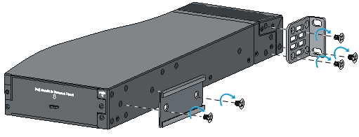
2. Attach the front mounting brackets and shoulder screws to the chassis:
a. Unpack the front mounting brackets and the M4 screws for attaching the brackets to the switch chassis.
b. Align the round holes in the wide flange of one front mounting bracket with the screw holes in the port-side mounting position on one side of the chassis (see Figure 12 and Figure 13).
c. Use M4 screws (supplied with the switch) to attach the mounting bracket to the chassis.
d. Repeat the proceeding two steps to attach the other mounting bracket to the chassis.
e. Unpack the shoulder screws. Attach the shoulder screw to one of the two installation positions as red-marked in Figure 12 and Figure 13.
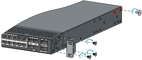
Figure 12 Attaching the front mounting brackets and shoulder screws to the chassis (S5130-30C-PWR-HI/S5130-54C-PWR-HI)
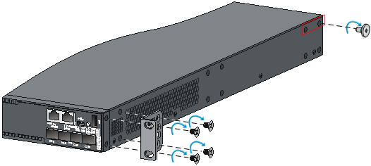
Figure 13 Attaching the front mounting brackets and shoulder screws to the chassis (S5130-54QS-HI)
3. Attach the rear mounting brackets to the rack:
a. Determine to orient the rear mounting brackets with the wide flange inside or outside the rack.
b. Install cage nuts (user-supplied) in the mounting holes in the rear rack posts. Make sure the corresponding cage nuts on the left and right rear rack posts are at the same height.
c. Attach the rear mounting brackets to the rear posts with M6 screws (user supplied), as shown in Figure 14. Do not completely fasten the screws until you mount the switch chassis in the rack.
Figure 14 Attaching the rear mounting brackets to a rack with the wide flange inside the rack
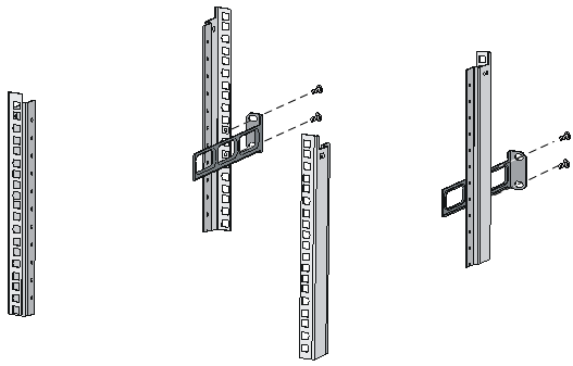
Figure 15 Attaching the rear mounting brackets to a rack with the wide flange outside the rack
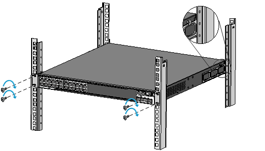
4. Mount the switch chassis in the rack:
a. Install cage nuts (user-supplied) in the mounting holes in the front rack posts. Make sure the corresponding cage nuts on the front and rear rack posts are at the same height.
b. One person supports the chassis bottom with one hand, holds the front part of the chassis with the other hand, and pushes the chassis into the rack gently.
Make sure the shoulder screws closely contact with the upper edges of the rear mounting brackets, as shown in Figure 16 and Figure 17.
c. The other person uses M6 screws (user-supplied) to attach the front mounting brackets to the front rack posts. Make sure the switch is installed securely in the rack.
Figure 16 Mounting the switch in the rack (with the wide flange of the mounting brackets inside the rack)

Rack-mounting by using front mounting brackets and mounting rail assemblies
This mounting method is applicable only to the S5130-54QS-HI switch.
You can install the front mounting brackets at the port-side or power-side mounting position as needed.
This task requires two people.
To install the switch in a 19-inch rack by using the front mounting brackets and mounting rail assemblies:
1. Wear an ESD wrist strap and make sure it makes good skin contact and is reliably grounded.
2. Attach the front mounting brackets and the chassis rails to the chassis (see Figure 18):
a. Unpack the front mounting brackets and the M4 screws for attaching the brackets to the switch chassis.
b. Align the round holes in the wide flange of one front mounting bracket with the screw holes in the power-side mounting position on one side of the chassis.
c. Use M4 screws (supplied with the switch) to attach the mounting bracket to the chassis.
d. Align one chassis rail with the screw holes in the chassis rail mounting position.
e. Use M4 screws (supplied with the switch) to attach the chassis rail to the chassis.
f. Repeat the proceeding steps to attach the other mounting bracket and chassis rail to the other side of the chassis.
Figure 18 Attaching the front mounting brackets and chassis rails to the chassis
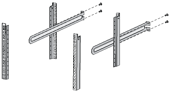
3. Attach the slide rails to the rack:
a. Identify the rack attachment position for the slide rails.
b. Install cage nuts (user-supplied) in the mounting holes in the rack posts.
c. Align the screw holes in one slide rail with the cage nuts in the rack post on one side, and use M6 screws (user supplied) to attach the slide rail to the rack, as shown in Figure 19.
d. Repeat the preceding step to attach the other slide rail to the rack post on the other side.
Keep the two slide rails at the same height so the slide rails can attach into the chassis rails.
Figure 19 Installing the slide rails
4. Mount the switch in the rack:
a. Verify that the front mounting brackets and chassis rails have been securely attached to the switch chassis.
b. Verify that the slide rails have been correctly attached to the rear rack posts.
c. Install cage nuts (user-supplied) to the front rack posts and make sure they are at the same level as the slide rails.
d. Supporting the bottom of the switch, align the chassis rails with the slide rails on the rack posts, as shown in Figure 20. Work with another person to slide the chassis rails along the slide rails until the mounting brackets are flush with the rack posts.
e. Use M6 screws (user-supplied) to attach the mounting brackets to the rack, as shown in Figure 21.
To secure the switch in the rack, make sure the front ends of the slide rails reach out of the chassis rails.
Figure 20 Mounting the switch in the rack (1)
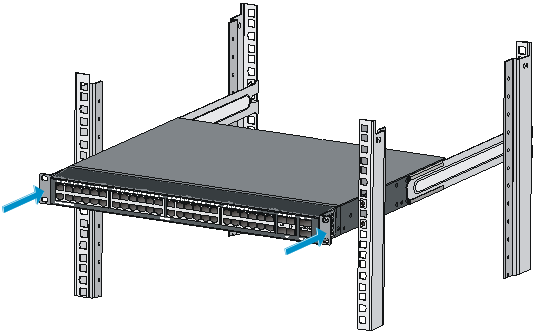
Figure 21 Mounting the switch in the rack (2)
Mounting the switch on a workbench
|
|
IMPORTANT: · Ensure good ventilation and 10 cm (3.9 in) of clearance around the chassis for heat dissipation. · Avoid placing heavy objects on the switch. |
To mount the switch on a workbench:
1. Verify that the workbench is sturdy and reliably grounded.
2. Place the switch with bottom up, and clean the round holes in the chassis bottom with dry cloth.
3. Attach the rubber feet to the four round holes in the chassis bottom.
4. Place the switch with upside up on the workbench.
Grounding the switch
|
|
WARNING! Correctly connecting the switch grounding cable is crucial to lightning protection and EMI protection. |
The power input end of the switch has a noise filter, whose central ground is directly connected to the chassis to form the chassis ground (commonly known as PGND). You must securely connect this chassis ground to the earth so the faradism and leakage electricity can be safely released to the earth to minimize EMI susceptibility of the switch.
You can ground the switch in one of the following ways, depending on the grounding conditions available at the installation site:
· Grounding the switch with a grounding strip
· Grounding the switch with a grounding conductor buried in the earth ground
|
|
NOTE: The power and grounding terminals in this section are for illustration only. |
Grounding the switch with a grounding strip
|
|
WARNING! Connect the grounding cable to the grounding system in the equipment room. Do not connect it to a fire main or lightning rod. |
If a grounding strip is available at the installation site, connect the grounding cable to the grounding strip.
Connecting the grounding cable to the chassis
1. Remove the grounding screw from the rear panel of the switch chassis.
2. Use the grounding screw to attach the ring terminal of the grounding cable to the grounding screw hole.
3. Verify that the grounding cable has been securely connected to the rear grounding point.
|
|
IMPORTANT: Orient the grounding cable as shown in Figure 22 so you can easily install or remove expansion card. |
Figure 22 Connecting the grounding cable to the chassis
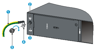
|
(1) Grounding cable |
(2) Grounding sign |
|
(3) Grounding hole |
(4) Ring terminal |
|
(5) Grounding screw |
|
Connecting the grounding cable to a grounding strip (S5130-30C-PWR-HI and S5130-54C-PWR-HI switches)
1. Remove the hex nut of a grounding post on the grounding strip.
2. Cut the grounding cable to a length required for connecting to the grounding strip.
3. Attach a ring terminal to the grounding cable:
a. Use a wire stripper to strip 5 mm (0.20 in) of insulation off the end of the grounding cable.
b. Slide the heat-shrink tubing onto the cable and insert the bare metal part into the end of the ring terminal.
c. Use a crimper to secure the metal part of the cable to the ring terminal.
d. Slide the heat-shrink tubing down the cable until the tube covers the joint.
e. Use a heat gun to shrink the tubing around the cable.
Figure 23 Attaching a ring terminal to the grounding cable

4. Connect the ring terminal to the grounding post of the grounding strip, and fasten it with the removed hex nut.
Figure 24 Connecting the grounding cable to a grounding strip
|
(1) Grounding post |
(2) Grounding strip |
|
(3) Grounding cable |
(4) Hex nut |
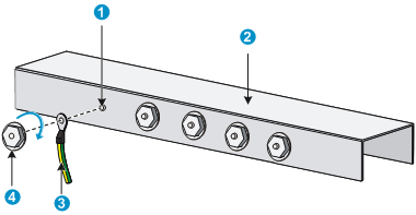
Connecting the grounding cable to a grounding strip (S5130-30S-HI, S5130-54S-HI, S5130-30F-HI, S5130-30C-HI, S5130-34C-HI, S5130-54C-HI, and S5130-54QS-HI switches)
1. Cut the grounding cable to a length required for connecting to the grounding strip.
2. Use a wire stripper to strip 20 mm (0.79 in) of insulation off the end of the grounding cable. Then use needle-nose pliers to bend the bare metal part to the shape as shown in Figure 25. Make sure the bended part can securely attached to the grounding post on the grounding strip.
3. Attach the bended part of the grounding cable to the grounding post and use the hex nut to fasten the bended part to the post.
Figure 25 Connecting the grounding cable to the grounding strip
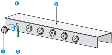
|
(1) Grounding post |
(2) Grounding strip |
|
(3) Grounding cable |
(4) Hex nut |
Grounding the switch with a grounding conductor buried in the earth ground
If the installation site does not have grounding strips, but earth ground is available, hammer a 0.5 m (1.64 ft) or longer angle iron or steel tube into the earth ground to serve as a grounding conductor.
The dimensions of the angle iron must be a minimum of 50 × 50 × 5 mm (1.97 × 1.97 × 0.20 in). The steel tube must be zinc-coated and its wall thickness must be a minimum of 3.5 mm (0.14 in).
Weld the yellow-green grounding cable to the angel iron or steel tube and treat the joint for corrosion protection.
Figure 26 Grounding the switch by burying the grounding conductor into the earth ground
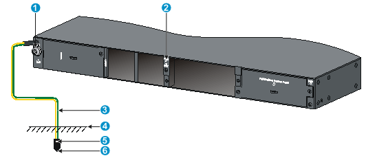
|
(1) Grounding screw |
(2) Chassis rear panel |
(3) Grounding cable |
|
(4) Earth |
(5) Joint |
(6) Grounding conductor |
Installing/removing a fan tray
|
|
CAUTION: · Install two fan trays of the same model on the switch. Do not power on the switch when it does not have a fan tray or has only one fan tray installed. · Make sure slots are installed with fan trays or blank filler panels for the device to operate. · If both fan trays fail during operation, replace them within 2 minutes while the switch is operating. · If one fan tray fails, perform either of the following tasks: ¡ If the ambient temperature is not higher than 27°C (80.6°F), replace the fan tray within 24 hours and make sure the failed fan tray is in position before the replacement. ¡ If the ambient temperature is higher than 27°C (80.6°F), replace the fan tray immediately. |
The S5130-30F-HI, S5130-30C-HI, S5130-34C-HI, S5130-54C-HI, S5130-30C-PWR-HI, S5130-54C-PWR-HI, and S5130-54QS-HI switches support hot-swappable fan trays.
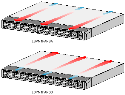
The switch comes with empty fan tray slots. Choose the fan tray models based on the ventilation requirement of the site. The air flow direction varies by fan tray model.
· The LSPM1FANSA has a blue handle and provides power-to-port air flow.
· The LSPM1FANSB has a red handle and provides port-to-power air flow.
For more information about the fan trays, see "Appendix B FRUs and compatibility matrixes."
Installing a fan tray
|
|
CAUTION: To prevent damage to the fan tray or the connectors on the backplane, insert the fan tray gently. If you encounter a hard resistance while inserting the fan tray, pull out the fan tray and insert it again. |
To install a fan tray:
1. Wear an ESD wrist strap and make sure it makes good skin contact and is reliably grounded.
2. Unpack the fan tray and verify that the fan tray model is correct.
3. Grasp the two handles of the fan tray with the side marked TOP facing up, and slide the fan tray along the guide rails into the slot until the fan tray seats in the slot and has a firm contact with the backplane.
Figure 27 Installing a fan tray
|
|
IMPORTANT: · At the first login to the switch, use the fan prefer-direction command to set the airflow direction of the switch to be the same as the airflow direction of the fan tray. If the fan tray has a different airflow direction than the switch, the system outputs traps and logs to notify you to replace the fan tray. · By default, the switch uses the same airflow direction (power-to-port) as the LSPM1FANSA fan tray. |
Removing a fan tray
|
|
WARNING! · Do not touch conductors or terminals on the fan trays. · Do not place the fan tray in moist place. Prevent liquid from entering the fan tray. · Fan trays with faulty internal wiring and conductors require maintenance from maintenance engineers. Do not disassemble the faulty fan trays. · Take out the fan tray after the fans completely stop rotating. Do not touch the fans even if the fans stop rotating to avoid affecting fan balance, which might cause loud fan operating noise. |
To remove a fan tray:
1. Wear an ESD wrist strap and make sure it makes good skin contact and is reliably grounded.
2. Grasp the two handles of the fan tray, as shown by callout 1 in Figure 28, and pull out the fan tray slowly along the guide rails.
3. Put the removed fan tray in an antistatic bag.
Installing/removing a power module
|
|
WARNING! In power redundancy mode, you can replace a power module without powering off the switch but you must strictly follow the installation and procedures in Figure 29 and Figure 30 to avoid any bodily injury or damage to the switch. |
|
|
CAUTION: Provide a circuit breaker for each power module. |
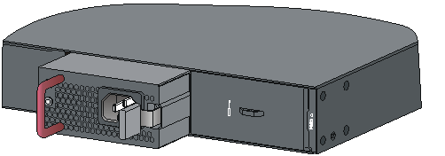
Figure 29 Installation procedure
![]()
![]()
Installing a PSR150 power module
|
|
CAUTION: To prevent damage to the power module or the connectors on the backplane, insert the power module gently. If you encounter a hard resistance when inserting the power module, pull out the power module and insert it again. |
For the PSR150-A1, and PSR150-D1 power modules, the installation and removal procedures are the same. The following takes the PSR150-A1 power module as an example.
To install a power module:
1. Wear an ESD wrist strap and make sure it makes good skin contact and is reliably grounded.
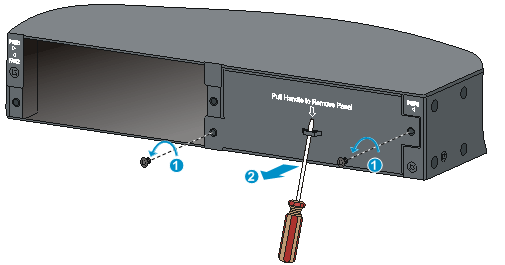
2. Remove the filler panel from the target power module slot as follows:
a. Remove the screws on the filler panel.
b. Use a flathead screwdriver to remove the filler panel.
Figure 31 Removing the filler panel
3. Unpack the power module and verify that the power module model is correct.
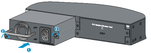
4. Correctly orient the power module with the power module slot (use the letters on the power module faceplate for orientation), grasp the handle of the power module with one hand and support its bottom with the other, and slide the power module slowly along the guide rails into the slot (see callout 1 in Figure 32).
5. Fasten the captive screws on the power module with a Phillips screwdriver to secure the power module in the chassis (see callout 2 in Figure 32). If the captive screw cannot be tightly fastened, verify the installation of the power module.
6. Install the filler panel over the empty power module slot to prevent dust and ensure good ventilation if you install only one power module.
Figure 32 Installing a PSR150-A1 power module
Removing a PSR150 power module
1. Wear an ESD wrist strap and make sure it makes good skin contact and is reliably grounded.
2. Disconnect the power cord.
3. Loosen the captive screws of the power module with a Phillips screwdriver until they are completely disengaged.
4. Grasp the handle of the power module with one hand and pull it out a little, support the bottom with the other hand, and pull the power module slowly along the guide rails out of the slot.
Put away the removed power module in an antistatic bag or the power module package bag for future use.
5. Install the filler panel to prevent dust and ensure good ventilation if no power module is installed in the slot.
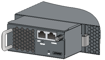
Installing a PSR360-56A/PSR720-56A/PSR1110-56A power module
|
|
CAUTION: To prevent damage to the power module or the connectors on the backplane, insert the power module gently. If you encounter a hard resistance when inserting the power module, pull out the power module and insert it again. |
For the PSR360-56A, PSR720-56A, and PSR1110-56A power modules, the installation and removal procedures are the same. The following takes the PSR720-56A power module as an example.
To install a power module:
1. Wear an ESD wrist strap and make sure it makes good skin contact and is reliably grounded.
2. Remove the filler panel, if any, from the target power module slot.
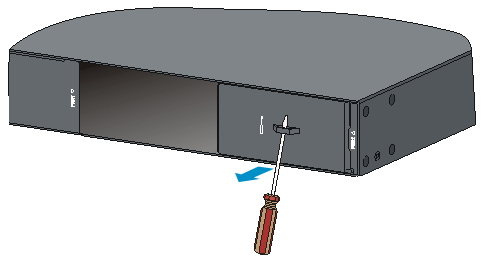
The power module slot filler panel varies by switch model. Follow the methods in Figure 33 or Figure 34 to remove the filler panel.
¡ Method 1: Insert the flathead screwdriver through the handle on the front panel and pull out the filler panel gently.
Figure 33 Removing the filler panel (1)
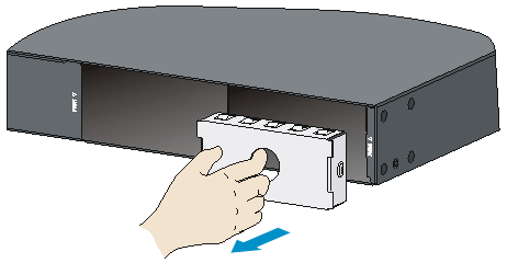
¡ Method 2: Put your forefinger into the hole in the front panel and pull out the filler panel gently.
Figure 34 Removing the filler panel (2)
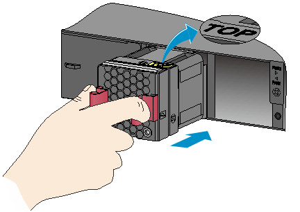
3. Unpack the power module and verify that the power module model is correct.
Put away the packaging box and packaging bag of the power module for future use.
4. Correctly orient the power module with the power module slot (use the letters on the power module faceplate for orientation), grasp the handle of the power module with one hand and support its bottom with the other, and slide the power module slowly along the guide rails into the slot until you hear that the latch of the power module clicks into the slot.
When you insert the power module into the slot, you can do that through slight inertia so that the terminals of the power module can have good contact with the backplane.
The PSR1110-56A power module adds 64 mm (2.52 in) to the depth of the switch, as shown in Figure 36.
5. Install the filler panel over the empty power module slot to prevent dust and ensure good ventilation if you install only one power module.
Figure 35 Installing a power module
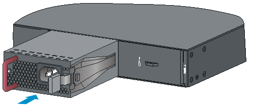
Figure 36 PSR1110-56A power module installed in the chassis
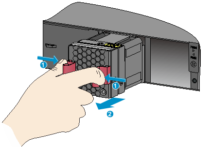
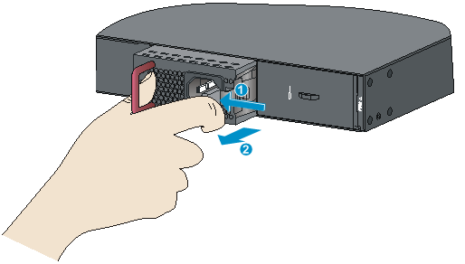
Removing a PSR360-56A/PSR720-56A/PSR1110-56A power module
1. Wear an ESD wrist strap and make sure it makes good skin contact and is reliably grounded.
2. Disconnect the power cord.
3. Press the latch towards the handle, and pull the power module along the guide rails until it is part-way out.
4. Grasp the handle of the power module with one hand, support the bottom with the other hand, and pull the power module slowly along the guide rails out of the slot.
Put away the removed power module in an antistatic bag or the power module package bag for future use.
5. Install the filler panel to prevent dust and ensure good ventilation if no power module is installed in the slot.
Figure 37 Removing the power module
Connecting the power cord
|
|
CAUTION: · The PSR150-A1 power modules each are provided with an AC power cord that uses a C13 connector. The PSR360-56A/PSR720-56A/PSR1110-56A power module is provided with an AC power cord that uses a high-temperature C15 connector. Do not confuse the power cords. · Provide a circuit breaker for each power module and make sure the circuit breaker is off before installation. |
Table 5 Power cord connection procedures at a glance
|
Power module |
Available power source |
Connection procedure reference |
|
Fixed power module |
AC input |
|
|
–48 VDC input |
||
|
External RPS power module RPS800-A or RPS1600-A |
||
|
PSR150-A1 |
AC input |
|
|
PSR150-D1 |
–48 VDC input |
|
|
External RPS power module RPS800-A or RPS1600-A |
||
|
PSR360-56A PSR720-56A PSR1110-56A |
AC input |
Connecting the AC power cord for a PSR360-56A, PSR720-56A, or PSR1110-56A power module |
Connecting the AC power cord for the fixed AC power module
1. Wear an ESD wrist strap and make sure it makes good skin contact and is reliably grounded.
2. Attach the hooks of the bail latch into the holes on the two sides of the AC-input power receptacle, and pull the bail latch upwards (see Figure 38).
3. Connect the female connector of the AC power cord to the AC-input power receptacle on the switch (see callout 1 in Figure 39).
4. Pull the bail latch down to secure the connector to the power receptacle (see callout 2 in Figure 39).
5. Connect the other end of the power cord to an AC power source.
Figure 38 Connecting the AC power cord for the fixed AC power module (1)
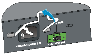
Figure 39 Connecting the AC power cord for the fixed AC power module (2)
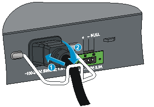
Connecting a DC power cord for the fixed DC power module
|
|
CAUTION: · The DC-input power receptacle on the switch requires a DC power cord with a JD5-A connector. · No DC power cord is provided with the switch. To use a –48 VDC power source for power supply, purchase an H3C recommended DC power cord yourself. To use an RPS for power supply, purchase a power cord compatible with the RPS yourself. · To connect a DC power cord to a –48 VDC power source, identify the positive (+) and negative (-) marks on the two wires of the power cord to avoid connection mistakes. |
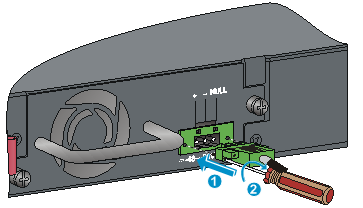
To connect a DC power cord for the fixed DC power module:
1. Wear an ESD wrist strap and make sure it makes good skin contact and is reliably grounded.
2. Correctly orient the DC power cord connector with the power receptacle on the power module, and insert the connector into the power receptacle. See callout 1 in Figure 40.
If you cannot insert the connector into the receptacle, re-orient the connector rather than use excessive force to push it in.
3. Fasten the screws on the connector with a flat-blade screwdriver to secure the connector in the power receptacle. See callout 2 in Figure 40.
4. Connect the other end of the power cord to a –48 VDC power source or an RPS.
Figure 40 Connecting a DC power cord for the fixed DC power module
Connecting the AC power cord for a PSR150-A1 power module
To connect the AC power cord for a PSR150-A1 power module:
1. Wear an ESD wrist strap and make sure it makes good skin contact and is reliably grounded.
2. Attach the hooks of the bail latch (supplied with the power module) into the two holes next to the power receptacle on the power module, and pull the bail latch leftwards (see Figure 41).
3. Connect the female connector of the AC power cord supplied with the power module to the power receptacle (see callout 1 in Figure 42).
4. Pull the bail latch rightwards to secure the connector to the power receptacle (see callout 2 in Figure 42).
5. Connect the other end of the power cord to an AC power source.
Figure 41 Connecting the power cord for a PSR150-A1 power module (1)
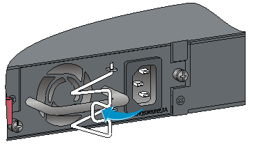
Figure 42 Connecting the power cord for a PSR150-A1 power module (2)
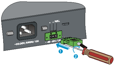
Connecting the DC power cord for a PSR150-D1 power module
|
|
CAUTION: · To connect to a –48 VDC power source, use the power cord shipped with the power module. · To connect to an H3C recommended RPS, use a power cord compatible with the RPS. · To connect a DC power cord to a –48 VDC power source, identify the positive (+) and negative (-) marks on the two wires of the power cord to avoid connection mistakes. |
To connect the DC power cord for a PSR150-D1 power module:
1. Wear an ESD wrist strap and make sure it makes good skin contact and is reliably grounded.
2. Unpack the DC power cord, correctly orient the connector of the DC power cord and align it with the power receptacle on the power module, and insert the connector into the power receptacle (see callout 1 in Figure 43).
The power receptacle is foolproof. If you cannot insert the connector into the receptacle, re-orient the connector rather than use excessive force to push it in.
3. Fasten the screws on the connector with a flat-blade screwdriver to secure the connector to the power receptacle (see callout 2 in Figure 43).
4. Connect the other end of the power cord to a –48 VDC power source or an RPS.
Figure 43 Connecting the DC power cord for a PSR150-D1 power module
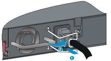
Connecting the AC power cord for a PSR360-56A, PSR720-56A, or PSR1110-56A power module
The following takes the PSR720-56A as an example. The connection procedure for the PSR360-56A and PSR1110-56A is similar.
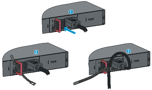
To connect the AC power cord for a PSR720-56A power module:
1. Wear an ESD wrist strap and make sure it makes good skin contact and is reliably grounded.
2. Plug the female connector end of the AC power cord into the AC input socket of the power module (see callout 1 in Figure 44).
3. Use a cable tie to secure the power cord to the handle of the power module (see callout 2 and callout 3 in Figure 44).
4. Connect the other end of the AC power cord to an AC power source.
Figure 44 Connecting the AC power cord for a PSR720-56A power module
Installing/removing an expansion card
The S5130-30C-HI, S5130-34C-HI, S5130-30F-HI, S5130-54C-HI, S5130-30C-PWR-HI, and S5130-54C-PWR-HI switches each have one expansion card slot and support hot swapping of an expansion card. For the expansion cards available for the switches, see "Appendix B FRUs and compatibility matrixes."
This section uses the LSWM2SP2PM card (with an ejector lever) and the LSPM6FWD card (without an ejector lever) as examples to describe the procedures for installing and removing an expansion card.
Installing an expansion card
1. Wear an ESD wrist strap and make sure it makes good skin contact and is reliably grounded.
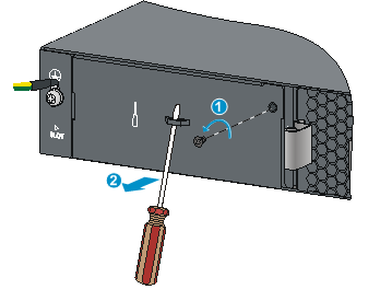
2. Use a Phillips screwdriver to remove the mounting screw on the filler panel over the expansion card slot. Then remove the filler panel. See Figure 45.
Keep the removed filler panel for future use.
Figure 45 Removing the filler panel over an expansion card slot
3. Unpack the expansion card.
4. Perform the following steps to install the expansion card:
a. Rotate rightward the ejector lever on the expansion card. Skip this step if the expansion card does not have an ejector lever.
b. Gently push the expansion card into the slot along the guide rails until the expansion card has good contact with the chassis.
The LSPM6FWD firewall card adds 75 mm (2.95 in) to the depth of the switch, as shown in Figure 48.
c. Rotate leftward the ejector lever. Skip this step if the expansion card does not have an ejector lever.
d. Use a Phillips screwdriver to fasten the captive screw on the front panel to secure the expansion card in the slot.
Figure 46 Installing an expansion card (LSWM2SP2PM)
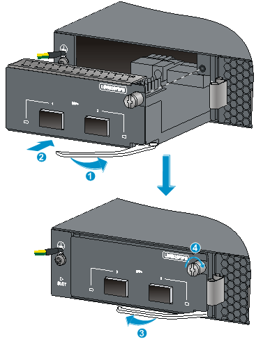
Figure 47 Installing an expansion card (LSPM6FWD)

Figure 48 LSPM6FWD firewall card installed in the chassis
Removing an expansion card
1. Wear an ESD wrist strap and make sure it makes good skin contact and is reliably grounded.
2. Use a Phillips screwdriver to completely loosen the captive screw on the expansion card.
3. Rotate rightward the ejector lever on the expansion card. Skip this step if the expansion card does not have an ejector lever.
4. Pull the expansion card out of the chassis gently along the guide rails.
Verifying the installation
After you complete the installation, verify the following information:
· There is enough space for heat dissipation around the switch, and the rack or workbench is stable.
· The grounding cable is securely connected.
· The correct power source is used.
· The power cords are correctly connected.
· All the interface cables are cabled indoors. If any cable is routed outdoors, verify that the socket strip with lightning protection and lightning arresters for network ports have been correctly connected.
Accessing the switch for the first time
Setting up the configuration environment
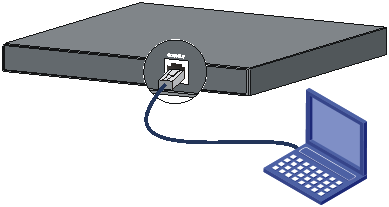
You can access the switch through the serial console port or the Mini USB console port. Only the Mini USB console port is available if you connect both the serial console port and Mini USB console port.
The switch is not provided with a serial console cable or Mini USB console cable. Prepare these cables yourself or purchase them from H3C.
Figure 49 Connecting the console port to a PC
Connecting the console cable
A console cable is an 8-core shielded cable, with a crimped RJ-45 connector at one end for connecting to the console port of the switch, and a DB-9 female connector at the other end for connecting to the serial port on the console terminal.
Figure 50 Console cable
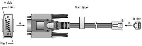
Table 6 Console port signaling and pinout
|
RJ-45 |
Signal |
DB-9 |
Signal |
|
1 |
RTS |
8 |
CTS |
|
2 |
DTR |
6 |
DSR |
|
3 |
TXD |
2 |
RXD |
|
4 |
SG |
5 |
SG |
|
5 |
SG |
5 |
SG |
|
6 |
RXD |
3 |
TXD |
|
7 |
DSR |
4 |
DTR |
|
8 |
CTS |
7 |
RTS |
To connect a configuration terminal (for example, a PC) to the switch:
1. Plug the DB-9 female connector of the console cable to the serial port of the PC.
2. Connect the RJ-45 connector to the console port of the switch.
|
|
NOTE: · Identify the mark on the console port and make sure you are connecting to the correct port. · The serial ports on PCs do not support hot swapping. To connect a PC to an operating switch, first connect the PC end. To disconnect a PC from an operating switch, first disconnect the switch end. |
Connecting the Mini USB console cable
A Mini USB console cable has a Mini USB Type B connector at one end to connect to the Mini USB console port of the switch, and a standard USB Type A connector at the other end to connect to the USB port on the PC.
To connect to the PC through the Mini USB console cable:
1. Connect the standard USB Type A connector to the USB port of the PC.
2. Connect the Mini USB Type B connector to the Mini USB console port of the switch.
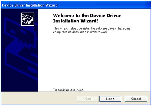
3. Click the following link, or copy it to the address bar on the browser to log in to download page of the USB console driver, and download the driver.
4. Select a driver program according to the operating system you use:
¡ XR21V1410_XR21B1411_Windows_Ver1840_x86_Installer.EXE—32-bit operating system.
¡ XR21V1410_XR21B1411_Windows_Ver1840_x64_Installer.EXE—64-bit operating system.
5. Click Next on the installation wizard.
Figure 51 Device Driver Installation Wizard
6. Click Continue Anyway if the following dialog box appears.
Figure 52 Software Installation

7. Click Finish.
Figure 53 Completing the device driver installation wizard
Setting terminal parameters
To configure and manage the switch through the console port, you must run a terminal emulator program, TeraTermPro or PuTTY, on your PC. You can use the emulator program to connect a network device, a Telnet site, or an SSH site. For more information about the terminal emulator programs, see the user guides for these programs.
The following are the required terminal settings:
· Bits per second—9,600.
· Data bits—8.
· Parity—None.
· Stop bits—1.
· Flow control—None.
Powering on the switch
Before powering on the switch, verify that the following conditions are met:
· The power cord is correctly connected.
· The input power voltage meets the requirement of the switch.
· The console cable is correctly connected.
· The PC has started, and its serial port settings are consistent with the console port settings on the switch.
Power on the switch. During the startup process, you can access Boot ROM menus to perform tasks such as software upgrade and file management. The Boot ROM interface and menu options differ with software versions. For more information about Boot ROM menu options, see the software-matching release notes for the device.
After the startup completes, you can access the CLI to configure the switch.
For more information about the configuration commands and CLI, see H3C S5130-HI Switch Series Configuration Guides and H3C S5130-HI Switch Series Command References.
Setting up an IRF fabric
You can use H3C IRF technology to connect and virtualize S5130-HI switches into a large virtual switch called an "IRF fabric" for flattened network topology, and high availability, scalability, and manageability.
IRF fabric setup flowchart
Figure 54 IRF fabric setup flowchart
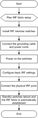
To set up an IRF fabric:
|
Step |
Description |
|
1. Plan IRF fabric setup |
Plan the installation site and IRF fabric setup parameters: · Planning IRF fabric size and the installation site · Identifying the master switch and planning IRF member IDs · Planning IRF topology and connections |
|
2. Install IRF member switches |
See "Installing the switch in a 19-inch rack" or "Mounting the switch on a workbench." |
|
3. Connect ground wires and power cords |
See "Grounding the switch" and "Connecting the power cord." |
|
4. Power on the switches |
N/A |
|
5. Configure basic IRF settings |
See H3C S5130-HI Switch Series IRF Configuration Guide. |
|
6. Connect the physical IRF ports |
Use SFP+ transceiver modules and fibers to connect SFP+ ports over a long distance. Use SFP+/QSFP+ network cables or twisted pair cables to connect SFP+ ports/QSFP+ ports over a short distance. All switches except the master switch automatically reboot, and the IRF fabric is established. |
Planning IRF fabric setup
This section describes issues that an IRF fabric setup plan must cover.
Planning IRF fabric size and the installation site
Choose switch models and identify the number of required IRF member switches, depending on the user density and upstream bandwidth requirements. The switching capacity of an IRF fabric equals the total switching capacities of all member switches.
Plan the installation site depending on your network solution, as follows:
· Place all IRF member switches in one rack for centralized high-density access.
· Distribute the IRF member switches in different racks to implement the ToR access solution for a data center.
|
|
NOTE: For the maximum number of IRF member devices in an S5130-HI IRF fabric, see the release notes. |
Identifying the master switch and planning IRF member IDs
Determine which switch you want to use as the master for managing all member switches in the IRF fabric.
An IRF fabric has only one master switch. You configure and manage all member switches in the IRF fabric at the CLI of the master switch. IRF member switches automatically elect a master.
You can affect the election result by assigning a high member priority to the intended master switch. For more information about master election, see H3C S5130-HI Switch Series IRF Configuration Guide.
Prepare an IRF member ID assignment scheme. An IRF fabric uses member IDs to uniquely identify and manage its members, and you must assign each IRF member switch a unique member ID.
Planning IRF topology and connections
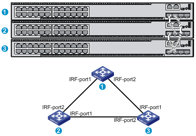
You can create an IRF fabric in daisy chain topology or more reliable ring topology. In ring topology, the failure of one IRF link does not cause the IRF fabric to split as in daisy chain topology. Instead, the IRF fabric changes to a daisy chain topology without interrupting network services.
You connect the IRF member switches through IRF ports, the logical interfaces for the connections between IRF member switches. Each IRF member switch has two IRF ports: IRF-port 1 and IRF-port 2. To use an IRF port, you must bind a minimum of one physical port to it.
When connecting two neighboring IRF member switches, you must connect the physical ports of IRF-port 1 on one switch to the physical ports of IRF-port 2 on the other switch.
As a best practice to avoid loop topology, first complete IRF configuration and then connect the IRF member switches.
The S5130-HI switches can provide 10-GE/20-GE IRF connections through 1/10 GE Ethernet ports/SFP+ ports/QSFP+ ports, and you can bind several 1/10 GE Ethernet ports/SFP+ ports/QSFP+ ports to an IRF port for increased bandwidth and availability.
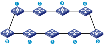
Figure 55 and Figure 56 show the topologies of an IRF fabric made up of three S5130-30C-HI switches. The IRF port connections in the two figures are for illustration only, and more connection methods are available.
Figure 55 IRF fabric in daisy chain topology
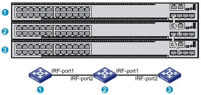
Figure 56 IRF fabric in ring topology
Identifying physical IRF ports on the member switches
Identify the physical IRF ports on the member switches according to your topology and connection scheme.
Table 7 shows the physical ports that can be used for IRF connection and the port use restrictions.
Table 7 Physical IRF port requirements
|
Chassis |
Candidate physical IRF ports |
Requirements |
|
· S5130-30S-HI · S5130-54S-HI |
· Four fixed SFP+ ports on the front panel · Two fixed QSFP+ ports on the rear panel |
· All physical ports to be bound to an IRF port must use the same port rate. · For the S5130-54QS-HI switch, SFP+ ports 49 to 52 form a group. When an SFP+ port is bound to an IRF port, other SFP+ ports in the same port group cannot be used as service ports, and vice versa. Each QSFP+ port is a group. · For other models, physical ports on different expansion cards can be bound to the same IRF port. |
|
S5130-54QS-HI |
Four fixed SFP+ ports and two fixed QSFP+ ports on the front panel |
|
|
· S5130-30F-HI · S5130-30C-HI · S5130-34C-HI · S5130-54C-HI · S5130-30C-PWR-HI · S5130-54C-PWR-HI |
· Four fixed SFP+ ports on the front panel · 1/10 GE Ethernet ports on the expansion card on the rear panel |
Planning the cabling scheme
Use twisted pair cables, SFP+/QSFP+ network cables, or SFP+ transceiver modules and fibers to connect the IRF member switches. If the IRF member switches are far away from one another, choose the SFP+ transceiver modules with optical fibers. If the IRF member switches are all in one equipment room, choose twisted pair cables or SFP+/QSFP+ network cables. For more information about SFP+/QSFP+ network cables and SFP+ transceiver modules, see "Appendix C Ports and LEDs."
The following subsections describe several H3C recommended IRF connection schemes, and all these schemes use a ring topology.
|
|
IMPORTANT: In these schemes, all physical IRF ports are located on the same side. If physical IRF ports are on different sides, you must measure the distance between them to select an appropriate cable. |
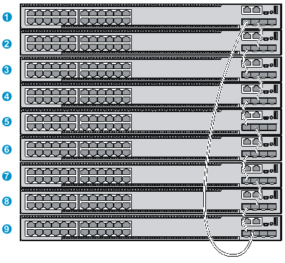
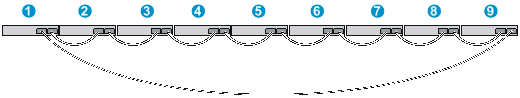
Connecting the IRF member switches in one rack
Use SFP+ network cables to connect the IRF member switches (9 switches in this example) in a rack as shown in Figure 57. The switches in the ring topology (see Figure 58) are in the same order as connected in the rack.
Figure 57 Connecting the switches in one rack
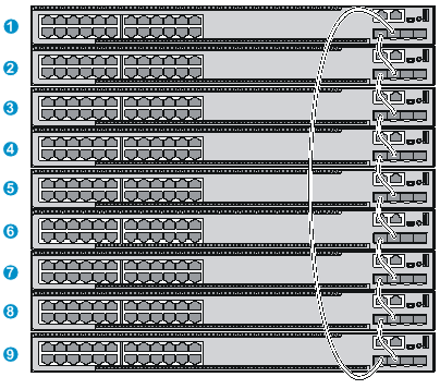
Connecting the IRF member switches in a ToR solution
You can install IRF member switches in different racks side by side to deploy a top of rack (ToR) solution.
Figure 59 shows an example for connecting 9 top of rack IRF member switches by using SFP+ transceiver modules and optical fibers. The topology is the same as Figure 58.
Configuring basic IRF settings
After you install the IRF member switches, power on the switches, and log in to each IRF member switch (see H3C S5130-HI Switch Series Fundamentals Configuration Guide) to configure their member IDs, member priorities, and IRF port bindings.
Follow these guidelines when you configure the switches:
· Assign the master switch higher member priority than any other switch.
· Bind physical ports to IRF port 1 on one switch and to IRF port 2 on the other switch. You perform IRF port binding before or after connecting IRF physical ports depending on the software release.
· To bind the ports on an interface card to an IRF port, you must install the interface card first. For how to install an interface card, see H3C S5130-HI Switch Series Interface Cards User Guide.
· Execute the display irf configuration command to verify the basic IRF settings.
For more information about configuring basic IRF settings, see H3C S5130-HI Switch Series IRF Configuration Guide.
Connecting the physical IRF ports
As a best practice to avoid loop topology, first complete IRF configuration and then connect the IRF member switches.
Use twisted pair cables, SFP+/QSFP+ network cables, or SFP+ transceiver modules and fibers to connect the IRF member switches as planned.
Wear an ESD wrist strap when you connect SFP+/QSFP+ network cables or SFP+ transceiver modules and fibers. For how to connect them, see H3C Transceiver Modules and Network Cables Installation Guide.
Verifying the IRF fabric setup
To verify the basic functionality of the IRF fabric after you finish configuring basic IRF settings and connecting IRF ports:
1. Log in to the IRF fabric through the console port of any member switch.
2. Create a Layer 3 interface, assign it an IP address, and make sure the IRF fabric and the remote network management station can reach each other.
3. Use Telnet, web, or SNMP to access the IRF fabric from the network management station. (See H3C S5130-HI Switch Series Fundamentals Configuration Guide.)
4. Verify that you can manage all member switches as if they were one node.
5. Display the running status of the IRF fabric by using the commands in Table 8.
Table 8 Displaying and maintaining IRF configuration and running status
|
Task |
Command |
|
Display information about the IRF fabric. |
display irf |
|
Display all members’ IRF configurations that take effect at a reboot. |
display irf configuration |
|
Display IRF fabric topology information. |
display irf topology |
|
|
NOTE: To avoid IP address collision and network problems, configure a minimum of one multi-active detection (MAD) mechanism to detect the presence of multiple identical IRF fabrics and handle collisions. For more information about MAD detection, see H3C S5130-HI Switch Series IRF Configuration Guide. |
Maintenance and troubleshooting
Power module failure
Fixed power module failure
The S5130-30S-HI and S5130-54S-HI switches use fixed power modules, and support three power input modes: AC input, RPS DC input, and concurrent AC and RPS DC inputs.
Look at the system status LED and the RPS status LED of the switch to identify power system failure.
Table 9 Description for the power failure indication LEDs
|
LED |
Mark |
Status |
Description |
|
System status LED |
SYS |
Off |
The switch is powered off. |
|
RPS status LED |
RPS |
Steady green |
The AC input is normal, and the RPS is in position or operating correctly. |
|
Steady yellow |
RPS power input is normal, but AC input has failed or AC input is not connected. |
||
|
Off |
No RPS is connected. |
AC input
· Symptom
The system status LED is off.
· Solution
To resolve the issue:
a. Verify that the AC power cord is securely connected to the switch, and the AC-input power receptacle on the switch and the connected AC power source are in good condition.
b. Verify that the external AC power system is operating correctly.
c. Verify that the operating temperature of the switch is in an acceptable range, and the power module has good ventilation. Over-temperature can cause the power module to stop working and enter protection state.
d. If the issue persists, contact H3C Support.
RPS DC input
· Symptom
The system status LED or RPS status LED is off.
· Solution
To resolve the issue:
a. Verify that the switch is securely connected to the RPS.
b. Verify that the RPS is operating correctly.
c. Verify that the operating temperature of the switch is in an acceptable range, and the power module has good ventilation. Over-temperature can cause the power module to stop working and enter protection state.
d. If the issue persists, contact H3C Support.
Concurrent RPS and AC inputs
· Symptom 1
The system status LED is off.
· Solution
To resolve the issue:
a. Verify that the AC power cord is securely connected to the switch, and the AC-input power receptacle on the switch and the connected AC power source are in good condition.
b. Verify that the external AC power system is operating correctly.
c. Verify that the switch is securely connected to the RPS.
d. Verify that the RPS is operating correctly.
e. Verify that the operating temperature of the switch is in an acceptable range, and the power module has good ventilation. Over-temperature can cause the power module to stop working and enter protection state.
f. If the issue persists, contact H3C Support.
· Symptom 2
The system status LED is on but the RPS status LED is steady yellow.
· Solution
To resolve the issue:
a. Verify that the AC power cord is securely connected to the switch, and the AC-input power receptacle on the switch and the connected AC power source are in good condition.
b. Verify that the external AC power system is operating correctly.
c. If the issue persists, contact H3C Support.
· Symptom 3
The system status LED is on but the RPS status LED is off.
· Solution
To resolve the issue:
a. Verify that the switch is securely connected to the RPS.
b. Verify that the RPS is operating correctly.
c. If the issue persists, contact H3C Support.
Hot swappable power module failure
This section applies to the S5130-30F-HI, S5130-30C-HI, S5130-34C-HI, S5130-54C-HI, S5130-30C-PWR-HI, S5130-54C-PWR-HI, and S5130-54QS-HI switches.
For the S5130-30F-HI, S5130-30C-HI, S5130-34C-HI, and S5130-54C-HI switches, examine the PWR1 or PWR2 LED of the switch to identify power module failure.
For the S5130-30C-PWR-HI and S5130-54C-PWR-HI switches, examine the PWR1 or PWR2 LED of the switch and the LEDs on the power module to identify power module failure.
· For more information about the PWR1 and PWR2 LEDs on the front panel of the switch, see Table 24.
· For more information about the LEDs on a power module, see H3C PSR360-56A Power Module User Manual, H3C PSR720-56A Power Module User Manual, and H3C PSR1110-56A Power Module User Manual.
S5130-30F-HI, S5130-30C-HI, S5130-54C-HI, S5130-30C-PWR-HI, S5130-54C-PWR-HI, or S5130-54QS-HI power module failure
· Symptom
The power module status LEDs are not steady green.
· Solution
To resolve the issue:
a. Verify that the switch power cord is correctly connected.
b. Verify that the power source meets the requirement.
c. Verify that the operating temperature of the switch is in an acceptable range and the power module has good ventilation.
d. If the issue persists, contact H3C Support.
To replace a hot swappable power module, see "Installing/removing a power module."
Fan failure
Fixed fan failure
The S5130-30S-HI and S5130-54S-HI switches use fixed fans. If a fan failure occurs, contact H3C Support and do not attempt to fix the problem yourself.
Hot swappable fan tray failure
|
|
WARNING! · Do not power on the switch when the switch does not have any fan trays or has only one fan tray installed. · If both fan trays fail during operation, replace them within 2 minutes while the switch is operating. · If one fan tray fails, perform either of the following tasks: ¡ If the ambient temperature is not higher than 27°C (80.6°F), replace the fan tray within 24 hours and make sure the failed fan tray is in position before the replacement. ¡ If the ambient temperature is higher than 27°C (80.6°F), replace the fan tray immediately. |
This section applies to the S5130-30F-HI, S5130-30C-HI, S5130-34C-HI, S5130-54C-HI, S5130-30C-PWR-HI, S5130-54C-PWR-HI, and S5130-54QS-HI switches.
The switch supports hot swapping of fan trays. When a fan tray fails, see "Installing/removing a fan tray" to replace the fan tray. If the issue persists, contact H3C Support.
Configuration terminal display problems
If the configuration environment setup is correct, the configuration terminal displays booting information when the switch is powered on. If the setup is incorrect, the configuration terminal displays nothing or garbled text.
No display
Symptom
The PC displays nothing when the switch is powered on.
Solution
To resolve the issue:
1. Verify that the power module is supplying power to the switch.
2. Verify that the console cable is correctly connected.
3. Verify that the console cable does not have any problems and the PC settings are correct.
4. If the issue persists, contact H3C Support.
Garbled display
Symptom
The display on the PC is garbled.
Solution
To resolve the issue:
1. Verify that the following settings are configured for the terminal:
¡ Baud rate—9,600.
¡ Data bits—8.
¡ Parity—None.
¡ Stop bits—1.
¡ Flow control—None.
2. If the issue persists, contact H3C Support.
Appendix A Chassis views and technical specifications
Chassis views
S5130-30S-HI
Figure 60 S5130-30S-HI front panel
|
(1) 10/100/1000BASE-T autosensing Ethernet port |
(2) 10/100/1000BASE-T autosensing Ethernet port LED |
|
(3) SFP+ port |
(4) Console port |
|
(5) Mini USB console port |
(6) Port LED mode switching button (MODE) |
|
(7) Port mode LED |
(8) USB port |
|
(9) System status LED (SYS) |
(10) RPS status LED (RPS) |
|
(11) SFP+ port LED |
|
Figure 61 S5130-30S-HI rear panel
|
(1) QSFP+ port LED |
(2) QSFP+ port |
|
(3) AC-input power receptacle |
(4) RPS receptacle |
|
(5) Grounding screw |
|
S5130-54S-HI
Figure 62 S5130-54S-HI front panel

|
(1) 10/100/1000BASE-T autosensing Ethernet port |
(2) 10/100/1000BASE-T autosensing Ethernet port LED |
|
(3) SFP+ port |
(4) Console port |
|
(5) Mini USB console port |
(6) Port LED mode switching button (MODE) |
|
(7) Port mode LED |
(8) USB port |
|
(9) System status LED (SYS) |
(10) RPS status LED (RPS) |
|
(11) SFP+ port LED |
|
Figure 63 S5130-54S-HI rear panel
|
(1) QSFP+ port LED |
(2) QSFP+ port |
|
(3) AC-input power receptacle |
(4) RPS receptacle |
|
(5) Grounding screw |
|
S5130-30F-HI
Figure 64 S5130-30F-HI front panel
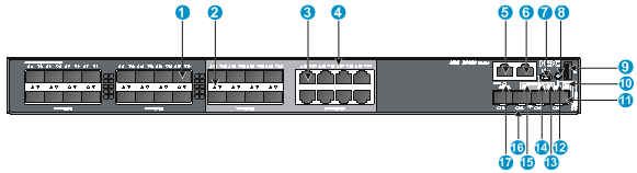
|
(1) SFP port |
(2) SFP port LED |
|
(3) 10/100/1000BASE-T autosensing Ethernet port |
(4) 10/100/1000BASE-T autosensing Ethernet port LED |
|
(5) Management Ethernet port |
(6) Console port |
|
(7) Mini USB console port |
(8) Port LED mode switching button (MODE) |
|
(9) USB port |
(10) System status LED (SYS) |
|
(11) SFP+ port |
(12) Port mode LED |
|
(13) Expansion card status LED (SLOT) |
(14) Power module 2 status LED (PWR2) |
|
(15) Power module 1 status LED (PWR1) |
(16) SFP+ port LED |
|
(17) Management Ethernet port LED |
|
Figure 65 S5130-30F-HI rear panel
|
(1) Grounding screw |
(2) Expansion card slot |
|
(3) Fan tray slot 1 |
(4) Fan tray slot 2 |
|
(5) Power module slot 1 |
(6) Power module slot 2 |
The S5130-30F-HI switch comes with power module slot 1 empty and power module slot 2 installed with a filler panel. You can install one or two power modules for the switch as required. In this figure, two PSR150-A1 AC power modules are installed in the power module slots. For more information about installing and removing a power module, see "Installing/removing a power module."
The S5130-30F-HI switch comes with the two fan tray slots empty. You must install two fan trays of the same model for the switch. In this figure, two LSPM1FANSA fan trays are installed in the fan tray slots. For more information about installing and removing a fan tray, see "Installing/removing a fan tray."
The S5130-30F-HI switch comes with a filler panel in the expansion card slot. You can select an expansion card for the switch as required. In this figure, an LSWM2SP2PM interface card is installed in the expansion card slot. For more information about installing and removing an expansion card, see "Installing/removing an expansion card."
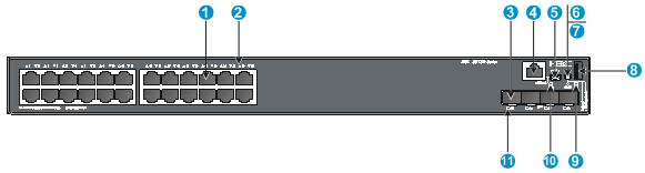
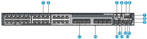
S5130-30C-HI
Figure 66 S5130-30C-HI front panel
|
(1) 10/100/1000BASE-T autosensing Ethernet port |
(2) 10/100/1000BASE-T autosensing Ethernet port LED |
|
(3) Management Ethernet port |
(4) Console port |
|
(5) Mini USB console port |
(6) Port LED mode switching button (MODE) |
|
(7) USB port |
(8) System status LED (SYS) |
|
(9) SFP+ port |
(10) Port mode LED |
|
(11) Expansion card status LED (SLOT) |
(12) Power module 2 status LED (PWR2) |
|
(13) Power module 1 status LED (PWR1) |
(14) SFP+ port LED |
|
(15) Management Ethernet port LED |
|
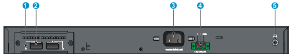
Figure 67 S5130-30C-HI rear panel
|
(1) Grounding screw |
(2) Expansion card slot |
|
(3) Fan tray slot 1 |
(4) Fan tray slot 2 |
|
(5) Power module slot 1 |
(6) Power module slot 2 |
The S5130-30C-HI switch comes with power module slot 1 empty and power module slot 2 installed with a filler panel. You can install one or two power modules for the switch as required. In this figure, two PSR150-A1 AC power modules are installed in the power module slots. For more information about installing and removing a power module, see "Installing/removing a power module."
The S5130-30C-HI switch comes with the two fan tray slots empty. You must install two fan trays of the same model for the switch. In this figure, two LSPM1FANSA fan trays are installed in the fan tray slots. For more information about installing and removing a fan tray, see "Installing/removing a fan tray."
The S5130-30C-HI switch comes with a filler panel in the expansion card slot. You can select an expansion card for the switch as required. In this figure, an LSWM2SP2PM interface card is installed in the expansion card slot. For more information about installing and removing an expansion card, see "Installing/removing an expansion card."
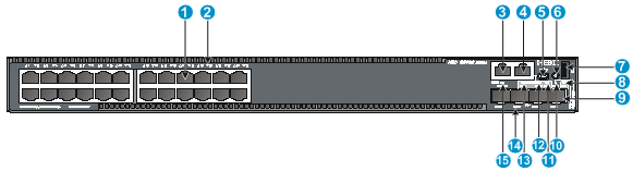
S5130-30C-PWR-HI
Figure 68 S5130-30C-PWR-HI front panel
|
(1) 10/100/1000BASE-T autosensing Ethernet port |
(2) 10/100/1000BASE-T autosensing Ethernet port LED |
|
(3) Management Ethernet port |
(4) Console port |
|
(5) Mini USB console port |
(6) Port LED mode switching button (MODE) |
|
(7) USB port |
(8) System status LED (SYS) |
|
(9) SFP+ port |
(10) Port mode LED |
|
(11) Expansion card status LED (SLOT) |
(12) Power module 2 status LED (PWR2) |
|
(13) Power module 1 status LED (PWR1) |
(14) SFP+ port LED |
|
(15) Management Ethernet port LED |
|
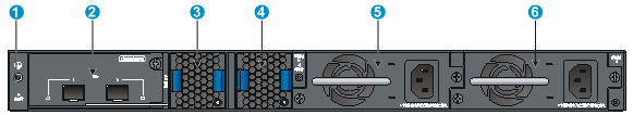
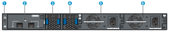
Figure 69 S5130-30C-PWR-HI rear panel
|
(1) Grounding screw |
(2) Expansion card slot |
|
(3) Fan tray slot 1 |
(4) Fan tray slot 2 |
|
(5) Power module slot 1 |
(6) Power module slot 2 |
The S5130-30C-PWR-HI switch comes with power module slot 1 empty and power module slot 2 installed with a filler panel. You can install one or two power modules for the switch as required. In this figure, two PSR720-56A AC power modules are installed in the power module slots. For more information about installing and removing a power module, see "Installing/removing a power module."
The S5130-30C-PWR-HI switch comes with the two fan tray slots empty. You must install two fan trays of the same model for the switch. In this figure, two LSPM1FANSA fan trays are installed in the fan tray slots. For more information about installing and removing a fan tray, see "Installing/removing a fan tray."
The S5130-30C-PWR-HI switch comes with a filler panel in the expansion card slot. You can select an expansion card for the switch as required. In this figure, an LSWM2SP2PM interface card is installed in the expansion card slot. For more information about installing and removing an expansion card, see "Installing/removing an expansion card."
S5130-34C-HI
Figure 70 S5130-34C-HI front panel
|
(1) 10/100/1000BASE-T autosensing Ethernet port |
(2) 10/100/1000BASE-T autosensing Ethernet port LED |
|
(3) Management Ethernet port |
(4) Console port |
|
(5) Mini USB console port |
(6) Port LED mode switching button (MODE) |
|
(7) USB port |
(8) System status LED (SYS) |
|
(9) SFP+ port |
(10) Port mode LED |
|
(11) Expansion card status LED (SLOT) |
(12) Power module 2 status LED (PWR2) |
|
(13) Power module 1 status LED (PWR1) |
(14) SFP+ port LED |
|
(15) Management Ethernet port LED |
(16) SFP port LED |
|
(17) SFP port |
|
Figure 71 S5130-34C-HI rear panel
|
(1) Grounding screw |
(2) Expansion card slot |
|
(3) Fan tray slot 1 |
(4) Fan tray slot 2 |
|
(5) Power module slot 1 |
(6) Power module slot 2 |
The S5130-34C-HI switch comes with power module slot 1 empty and power module slot 2 installed with a filler panel. You can install one or two power modules for the switch as required. In this figure, two PSR150-A1 AC power modules are installed in the power module slots. For more information about installing and removing a power module, see "Installing/removing a power module."
The S5130-34C-HI switch comes with the two fan tray slots empty. You must install two fan trays of the same model for the switch. In this figure, two LSPM1FANSA fan trays are installed in the fan tray slots. For more information about installing and removing a fan tray, see "Installing/removing a fan tray."
The S5130-34C-HI switch comes with a filler panel in the expansion card slot. You can select an expansion card for the switch as required. In this figure, an LSWM2SP2PM interface card is installed in the expansion card slot. For more information about installing and removing an expansion card, see "Installing/removing an expansion card."
S5130-54C-HI
Figure 72 S5130-54C-HI front panel
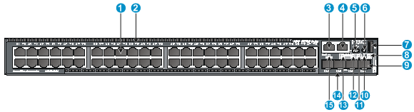
|
(1) 10/100/1000BASE-T autosensing Ethernet port |
(2) 10/100/1000BASE-T autosensing Ethernet port LED |
|
(3) Management Ethernet port |
(4) Console port |
|
(5) Mini USB console port |
(6) Port LED mode switching button (MODE) |
|
(7) USB port |
(8) System status LED (SYS) |
|
(9) SFP+ port |
(10) Port mode LED |
|
(11) Expansion card status LED (SLOT) |
(12) Power module 2 status LED (PWR2) |
|
(13) Power module 1 status LED (PWR1) |
(14) SFP+ port LED |
|
(15) Management Ethernet port LED |
|
Figure 73 S5130-54C-HI rear panel
|
(1) Grounding screw |
(2) Expansion card slot |
|
(3) Fan tray slot 1 |
(4) Fan tray slot 2 |
|
(5) Power module slot 1 |
(6) Power module slot 2 |
The S5130-54C-HI switch comes with power module slot 1 empty and power module slot 2 installed with a filler panel. You can install one or two power modules for the switch as required. In this figure, two PSR150-A1 AC power modules are installed in the power module slots. For more information about installing and removing a power module, see "Installing/removing a power module."
The S5130-54C-HI switch comes with the two fan tray slots empty. You must install two fan trays of the same model for the switch. In this figure, two LSPM1FANSA fan trays are installed in the fan tray slots. For more information about installing and removing a fan tray, see "Installing/removing a fan tray."
The S5130-54C-HI switch comes with a filler panel in the expansion card slot. You can select an expansion card for the switch as required. In this figure, an LSWM2SP2PM interface card is installed in the expansion card slot. For more information about installing and removing an expansion card, see "Installing/removing an expansion card."
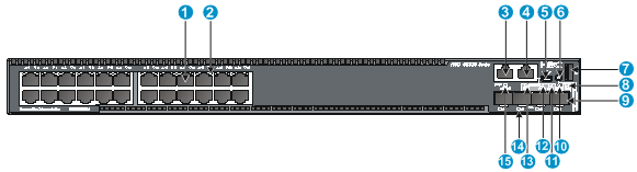
S5130-54C-PWR-HI
Figure 74 S5130-54C-PWR-HI front panel
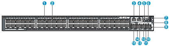
|
(1) 10/100/1000BASE-T autosensing Ethernet port |
(2) 10/100/1000BASE-T autosensing Ethernet port LED |
|
(3) Management Ethernet port |
(4) Console port |
|
(5) Mini USB console port |
(6) Port LED mode switching button (MODE) |
|
(7) USB port |
(8) System status LED (SYS) |
|
(9) SFP+ port |
(10) Port mode LED |
|
(11) Expansion card status LED (SLOT) |
(12) Power module 2 status LED (PWR2) |
|
(13) Power module 1 status LED (PWR1) |
(14) SFP+ port LED |
|
(15) Management Ethernet port LED |
|
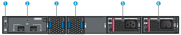
Figure 75 S5130-54C-PWR-HI rear panel
|
(1) Grounding screw |
(2) Expansion card slot |
|
(3) Fan tray slot 1 |
(4) Fan tray slot 2 |
|
(5) Power module slot 1 |
(6) Power module slot 2 |
The S5130-54C-PWR-HI switch comes with power module slot 1 empty and power module slot 2 installed with a filler panel. You can install one or two power modules for the switch as required. In this figure, two PSR720-56A AC power modules are installed in the power module slots. For more information about installing and removing a power module, see "Installing/removing a power module."
The S5130-54C-PWR-HI switch comes with the two fan tray slots empty. You must install two fan trays of the same model for the switch. In this figure, two LSPM1FANSA fan trays are installed in the fan tray slots. For more information about installing and removing a fan tray, see "Installing/removing a fan tray."
The S5130-54C-PWR-HI switch comes with a filler panel in the expansion card slot. You can select an expansion card for the switch as required. In this figure, an LSWM2SP2PM interface card is installed in the expansion card slot. For more information about installing and removing an expansion card, see "Installing/removing an expansion card."
S5130-54QS-HI
Figure 76 S5130-54QS-HI front panel
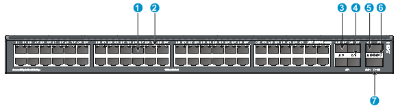
|
(1) 10/100/1000BASE-T autosensing Ethernet port |
(2) 10/100/1000BASE-T autosensing Ethernet port LED |
|
(3) SFP+ port |
(4) SFP+ port LED |
|
(5) QSFP+ port |
(6) QSFP+ port LED |
|
(7) System status LED (SYS) |
|
Figure 77 S5130-54QS-HI rear panel
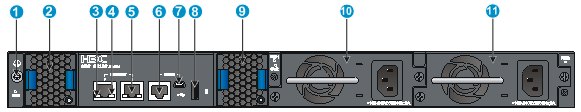
|
(1) Grounding screw |
(2) Fan tray slot 1 |
|
(3) ACT LED for the management Ethernet port |
(4) LINK LED for the management Ethernet port |
|
(5) Management Ethernet port |
(6) Console port |
|
(7) Mini USB console port |
(8) USB port |
|
(9) Fan tray slot 2 |
(10) Power module slot 1 |
|
(11) Power module slot 2 |
|
The S5130-54QS-HI switch comes with power module slot 1 empty and power module slot 2 installed with a filler panel. You can install one or two power modules for the switch as required. In this figure, two PSR150-A1 AC power modules are installed in the power module slots. For more information about installing and removing a power module, see "Installing/removing a power module."
The S5130-54QS-HI switch comes with the two fan tray slots empty. You must install two fan trays of the same model for the switch. In this figure, two LSPM1FANSA fan trays are installed in the fan tray slots. For more information about installing and removing a fan tray, see "Installing/removing a fan tray."
Technical specifications
Table 10 Technical specifications for non-PoE switch models (1)
|
Item |
S5130-30S-HI |
S5130-54S-HI |
S5130-30F-HI |
S5130-30C-HI |
|
Dimensions (H × W × D) |
43.6 × 440 × 260 mm (1.72 × 17.32 ×10.24 in) |
43.6 × 440 × 260 mm (1.72 × 17.32 ×10.24 in) |
43.6 × 440 × 360 mm (1.72 × 17.32 × 14.17 in) |
43.6 × 440 × 360 mm (1.72 × 17.32 × 14.17 in) |
|
Weight |
≤ 5 kg (11.02 lb) |
≤ 5 kg (11.02 lb) |
≤ 7.5 kg (16.53 lb) |
≤ 7.5 kg (16.53 lb) |
|
Console ports |
· 1 × Mini USB console port · 1 × serial console port Only the Mini USB console port is available when you connect both ports. |
|||
|
USB ports |
1 |
1 |
1 |
1 |
|
Management Ethernet ports |
N/A |
N/A |
1 |
1 |
|
QSFP+ ports |
2 |
2 |
N/A |
N/A |
|
SFP+ ports |
4 |
4 |
4 |
4 |
|
SFP ports |
N/A |
N/A |
24 (The rightmost eight SFP ports and their corresponding 10/100/1000BASE-T autosensing Ethernet ports form combo interfaces.) |
N/A |
|
10/100/1000BASE-T autosensing Ethernet ports |
24 |
48 |
8 (Each and its corresponding SFP port form a combo interface.) |
24 |
|
Expansion card slots |
N/A |
N/A |
1, on the rear panel |
1, on the rear panel |
|
Power module slots |
N/A |
N/A |
2, on the rear panel |
2, on the rear panel |
|
Fan tray slots |
N/A |
N/A |
2, on the rear panel |
2, on the rear panel |
|
Input voltage |
· AC-input ¡ Rated voltage range: 100 VAC to 240 VAC @ 50 Hz or 60 Hz ¡ Max voltage range: 90 VAC to 264 VAC @ 47 Hz to 63 Hz · DC-input ¡ Rated voltage range: –48 VDC to –60 VDC ¡ Max voltage range: –36 VDC to –72 VDC NOTE: You can use the site –48 VDC power source or an H3C RPS800-A or RPS1600-A RPS as the DC power source. |
|||
|
Minimum power consumption |
· AC: 35 W · DC: 34 W |
· AC: 45 W · DC: 44 W |
· Single AC input: 32 W · Single DC input: 35 W · Dual AC inputs: 38 W · Dual DC inputs: 42 W |
· Single AC input: 37 W · Single DC input: 42 W · Dual AC inputs: 43 W · Dual DC inputs: 49 W |
|
Maximum power consumption |
· AC: 52 W · DC: 50 W |
· AC: 64 W · DC: 65 W |
· Single AC input: 67 W · Single DC input: 69 W · Dual AC inputs: 73 W · Dual DC inputs: 78 W |
· Single AC input: 72 W · Single DC input: 75 W · Dual AC inputs: 77 W · Dual DC inputs: 80 W |
|
Chassis leakage current compliance |
UL60950-1, EN60950-1, IEC60950-1, GB4943 |
|||
|
Melting current of power module fuse |
· AC-input: 3.15 A, 250 V · DC-input: 8 A, 250 V |
· AC-input: 3.15 A, 250 V · DC-input: 8 A, 250 V |
· AC-input: 6.3 A, 250 V · DC-input: 8 A, 250 V |
· AC-input: 6.3 A, 250 V · DC-input: 8 A, 250 V |
|
Operating temperature |
-5°C to 45°C (23°F to 113°F) |
|||
|
Relative humidity |
5% to 95%, noncondensing |
|||
|
Fire resistance compliance |
UL60950-1, EN60950-1, IEC60950-1, GB4943 |
|||
Table 11 Technical specifications for non-PoE switch models (2)
|
S5130-34C-HI |
S5130-54C-HI |
S5130-54QS-HI |
|
|
Dimensions (H × W × D) |
43.6 × 440 × 360 mm (1.72 × 17.32 × 14.17 in) |
43.6 × 440 × 360 mm (1.72 × 17.32 × 14.17 in) |
43.6 × 440 × 360 mm (1.72 × 17.32 × 14.17 in) |
|
Weight |
≤ 7.5 kg (16.53 lb) |
≤ 7.5 kg (16.53 lb) |
≤ 7.5 kg (16.53 lb) |
|
Console ports |
· 1 × Mini USB console port · 1 × serial console port Only the Mini USB console port is available when you connect both ports. |
||
|
USB ports |
1 |
1 |
1 |
|
Management Ethernet ports |
1 |
1 |
2 |
|
QSFP+ ports |
N/A |
N/A |
2 |
|
SFP+ ports |
4 |
4 |
4 |
|
SFP ports |
8 (Each and its corresponding 10/100/1000BASE-T autosensing Ethernet port form a combo interface.) |
N/A |
N/A |
|
10/100/1000BASE-T autosensing Ethernet ports |
28 (The rightmost eight 10/100/1000BASE-T autosensing Ethernet ports and their corresponding SFP ports form combo interfaces.) |
48 |
24 |
|
Expansion card slots |
1, on the rear panel |
1, on the rear panel |
N/A |
|
Power module slots |
2, on the rear panel |
2, on the rear panel |
2, on the rear panel |
|
Fan tray slots |
2, on the rear panel |
2, on the rear panel |
2, on the rear panel |
|
Input voltage |
· AC-input ¡ Rated voltage range: 100 VAC to 240 VAC @ 50 Hz or 60 Hz ¡ Max voltage range: 90 VAC to 264 VAC @ 47 Hz to 63 Hz · DC-input ¡ Rated voltage range: –48 VDC to –60 VDC ¡ Max voltage range: –36 VDC to –72 VDC NOTE: You can use the site –48 VDC power source or an H3C RPS800-A or RPS1600-A RPS as the DC power source. |
||
|
Minimum power consumption |
· Single AC input: 37 W · Single DC input: 39 W · Dual AC inputs: 42 W · Dual DC inputs: 48 W |
· Single AC input: 45 W · Single DC input: 48 W · Dual AC inputs: 50 W · Dual DC inputs: 54 W |
· Single AC input: 58 W · Single DC input: 62 W · Dual AC inputs: 63 W · Dual DC inputs: 67 W |
|
Maximum power consumption |
· Single AC input: 78 W · Single DC input: 79 W · Dual AC inputs: 80 W · Dual DC inputs: 86 W |
· Single AC input: 83 W · Single DC input: 84 W · Dual AC inputs: 88 W · Dual DC inputs: 93 W |
· Single AC input: 90 W · Single DC input: 92 W · Dual AC inputs: 95 W · Dual DC inputs: 100 W |
|
Chassis leakage current compliance |
UL60950-1, EN60950-1, IEC60950-1, GB4943 |
||
|
Melting current of power module fuse |
· AC-input: 6.3 A, 250V · DC-input: 8 A, 250V |
||
|
Operating temperature |
-5°C to 45°C (23°F to 113°F) |
||
|
Relative humidity |
5% to 95%, noncondensing |
||
|
Fire resistance compliance |
UL60950-1, EN60950-1, IEC60950-1, GB4943 |
||
Table 12 Technical specifications for PoE switch models
|
Item |
S5130-30C-PWR-HI |
S5130-54C-PWR-HI |
|
Dimensions (H × W × D) |
43.6 × 440 × 460 mm (1.72 × 17.32 × 18.11 in) |
43.6 × 440 × 460 mm (1.72 × 17.32 × 18.11 in) |
|
Weight |
≤ 10 kg (22.05 lb) |
≤ 10.5 kg (23.15 lb) |
|
Console ports |
· 1 × Mini USB console port · 1 × serial console port Only the Mini USB console port is available when you connect both ports. |
|
|
USB ports |
1 |
1 |
|
Management Ethernet ports |
1 |
1 |
|
SFP+ ports |
4 |
4 |
|
10/100/1000BASE-T autosensing Ethernet ports |
24 |
48 |
|
Expansion card slots |
1, on the rear panel |
1, on the rear panel |
|
Power module slots |
2, on the rear panel |
2, on the rear panel |
|
Fan tray slots |
2, on the rear panel |
2, on the rear panel |
|
Input voltage |
· PSR360-56A/PSR720-56A AC-input ¡ Rated voltage range: 100 VAC to 240 VAC @ 50 Hz or 60 Hz ¡ Max voltage range: 90 VAC to 264 VAC @ 47 Hz to 63 Hz · PSR1110-56A AC-input ¡ Rated voltage range: 115 VAC to 240 VAC @ 50 Hz or 60 Hz ¡ Max voltage range: 102.5 VAC to 264 VAC @ 47 Hz to 63 Hz |
|
|
PoE power capacity |
Depends on the power module configurations. For more information, see the following table. |
|
|
Minimum power consumption |
44 W |
67 W |
|
Maximum power consumption (including PoE power consumption) |
991 W |
1950 W |
|
Chassis leakage current compliance |
UL60950-1, EN60950-1, IEC60950-1, GB4943 |
|
|
Melting current of power module fuse |
15 A, 250V |
|
|
Operating temperature |
-5°C to 45°C (23°F to 113°F) |
|
|
Relative humidity |
5% to 95%, noncondensing |
|
|
Fire resistance compliance |
UL60950-1, EN60950-1, IEC60950-1, GB4943 |
|
The following table describes PoE power capacity for the S5130-30C-PWR-HI and S5130-54C-PWR-HI switches:
|
Power module configuration |
S5130-30C-PWR-HI |
S5130-54C-PWR-HI |
||
|
Total PoE power capacity |
Max PoE power capacity per port |
Total PoE power capacity |
Max PoE power capacity per port |
|
|
2 × PSR1110-56A |
810 W |
30 W |
1680 W |
30 W |
|
1 × PSR1110-56A and 1 × PSR720-56A |
810 W |
30 W |
1560 W |
30 W |
|
1 × PSR1110-56A and 1 × PSR360-56A |
810 W |
30 W |
1200 W |
30 W |
|
2 × PSR720-56A |
810 W |
30 W |
1200 W |
30 W |
|
1 × PSR1110-56A |
810 W |
30 W |
810 W |
30 W |
|
1 × PSR720-56A and 1 × PSR360-56A |
810 W |
30 W |
810 W |
30 W |
|
1 × PSR720-56A |
450 W |
30 W |
450 W |
30 W |
|
2 × PSR360-56A |
450 W |
30 W |
450 W |
30 W |
|
1 × PSR360-56A |
180 W |
30 W |
180 W |
30 W |
|
|
NOTE: The total PoE power capacity varies by software version. For more information, see the release notes for the switch. |
Appendix B FRUs and compatibility matrixes
FRUs and compatibility matrixes
|
FRUs |
S5130-30S-HI S5130-54S-HI |
S5130-30C-HI S5130-54C-HI S5130-34C-HI S5130-30F-HI |
S5130-30C-PWR-HI S5130-54C-PWR-HI |
S5130-54QS-HI |
|
Hot swappable power modules |
||||
|
PSR150-A1 |
N/A |
Supported |
N/A |
Supported |
|
PSR150-D1 |
N/A |
Supported |
N/A |
Supported |
|
PSR360-56A |
N/A |
N/A |
Supported |
N/A |
|
PSR720-56A |
N/A |
N/A |
Supported |
N/A |
|
PSR1110-56A |
N/A |
N/A |
Supported |
N/A |
|
Hot swappable fan trays |
||||
|
LSPM1FANSA |
N/A |
Supported |
Supported |
Supported |
|
LSPM1FANSB |
N/A |
Supported |
Supported |
Supported |
|
Expansion cards |
||||
|
LSWM2SP2PM |
N/A |
Supported |
Supported |
N/A |
|
LSWM2XGT2PM |
N/A |
Supported |
Supported |
N/A |
|
LSPM6QP2PS |
N/A |
Supported |
Supported |
N/A |
|
LSPM6FWD |
N/A |
Supported |
N/A |
N/A |
The PSR360-56A, PSR720-56A, PSR1110-56A, PSR150-A1, and PSR150-D1 power modules support asset management. You can use the display device manuinfo command to view the name, sequence number, and vendor of the power modules you have installed on the device.
You can install one power module, or two power modules for redundancy on the S5130-30C-HI, S5130-34C-HI, S5130-30F-HI, S5130-54C-HI, and S5130-54QS-HI switches. These switches support mix of an AC power module and a DC power module.
You can install one power module, or two power modules for redundancy on the S5130-30C-PWR-HI and S5130-54C-PWR-HI switches. The PoE capabilities of these switches vary by power module configuration. For more information, see Table 11.
All S5130-HI switch models except the S5130-30S-HI and S5130-54S-HI switches support hot swapping of fan trays. You must install two fan trays of the same model for the switch. Do not power on the switch when it does not have any fan trays or has only one fan tray installed.
Support for the LSPM6QP2PS and LSPM6FWD cards varies by software version. For more information, see the release notes for the switch.
Hot swappable power modules
All S5130-HI switch models except the S5130-30S-HI and S5130-54S-HI switches support hot swapping of power modules. The following table describes power modules available for the switch.
|
Power module |
Specifications |
Reference |
|
PSR150-A1 |
· Rated input voltage range: 100 VAC to 240 VAC @ 50 Hz or 60 Hz · Max input voltage range: 90 VAC to 264 VAC @ 47 Hz to 63 Hz · Max output power: 150 W |
H3C PSR150-A & PSR150-D Series Power Modules User Manual |
|
PSR150-D1 |
· Rated input voltage range: –48 VDC to –60 VDC · Max input voltage range: –36 VDC to –72 VDC · Max output power: 150 W |
H3C PSR150-A & PSR150-D Series Power Modules User Manual |
|
PSR360-56A |
· Rated input voltage range: 100 VAC to 240 VAC @ 50 Hz or 60 Hz · Max input voltage range: 90 VAC to 264 VAC @ 47 Hz to 63 Hz · Max output power: 360 W |
H3C PSR360-56A Power Module User Manual |
|
PSR720-56A |
· Rated input voltage range: 100 VAC to 240 VAC @ 50 Hz or 60 Hz · Max input voltage range: 90 VAC to 264 VAC @ 47 Hz to 63 Hz · Max output power: 720 W |
H3C PSR720-56A Power Module User Manual |
|
PSR1110-56A |
· Rated input voltage range: 115 VAC to 240 VAC @ 50 Hz or 60 Hz · Max input voltage range: 102.5 VAC to 264 VAC @ 47 Hz to 63 Hz · Max output power: 1110 W |
H3C PSR1110-56A Power Module User Manual |
|
|
NOTE: The PSR1110-56A power module adds 64 mm (2.52 in) to the depth of the switch, including the depth of the power module handle. |
Hot swappable fan trays
All S5130-HI switch models, except the S5130-30S-HI and S5130-54S-HI switches, support the LSPM1FANSA and LSPM1FANSB fan trays. The following table describes the specifications for the LSPM1FANSA and LSPM1FANSB fan trays.
|
Item |
Specifications |
|
LSPM1FANSA fan tray |
|
|
Dimensions |
40 × 40 × 104 mm (1.57 × 1.57 × 4.09 in) |
|
Fan speed |
20000 R.P.M |
|
Max airflow |
20 CFM |
|
Airflow direction |
Back to front (from the power module side to the network port side) |
|
Input voltage |
12 V |
|
Maximum power consumption |
9.8 W |
|
Reference |
H3C LSPM1FANSA & LSPM1FANSB Fan Trays User Guide |
|
LSPM1FANSB fan tray |
|
|
Dimensions |
40 × 40 × 104 mm (1.57 × 1.57 × 4.09 in) |
|
Fan speed |
20000 R.P.M |
|
Max airflow |
20 CFM |
|
Airflow direction |
Front to back (from the network port side to the power module side) |
|
Input voltage |
12 V |
|
Maximum power consumption |
9.8 W |
|
Reference |
H3C LSPM1FANSA & LSPM1FANSB Fan Trays User Guide |
Hot swappable expansion cards
The S5130-30C-HI, S5130-34C-HI, S5130-30F-HI, S5130-54C-HI, S5130-30C-PWR-HI, and S5130-54C-PWR-HI switches provide an expansion card slot at the rear. The following table describes the expansion cards available for these switches.
|
Card type |
Card model |
Port type and quantity |
Remarks |
|
Interface card |
LSWM2SP2PM |
2 × 1/10 GE SFP+ fiber port |
For available transceiver modules and cables, see Table 20 and Table 21. |
|
LSWM2XGT2PM |
2 × 1/10GBASE-T Ethernet port |
For port specifications, see Table 16. |
|
|
LSPM6QP2PS |
2 × 20 GE QSFP+ port |
For available cables, see Table 22. |
|
|
Service card |
LSPM6FWD |
N/A |
It is the fourth-generation firewall card developed by H3C, integrating firewall, VPN, content filtering and identification, URL filtering, and NAT features. |
For more information about these interface cards, see user manuals for the interface cards. For more information about the service card, see its card manual.
|
|
NOTE: · When you install the LSWM2SP2PM and LSWM2XGT2PM interface cards on the switch, the ports on the interface cards can operate only at 10 Gbps. · The LSPM6FWD firewall card adds 75 mm (2.95 in) to the depth of the switch, as shown in Figure 48. |
Connecting cables to the copper ports on the interface cards
The LSWM2XGT2PM interface card provides copper ports. To connect cables to the copper ports on the LSWM2XGT2PM interface card, follow these guidelines:
· Use Category-6A or above cables and connectors. The max transmission distance varies by cable type:
¡ Category-6 UTP—55 m (180.45 ft).
¡ Category-6 STP—100 m (328.084 ft), no interference.
¡ Category-6 SFTP—100 m (328.084 ft).
¡ Category-6A and above twisted pair—100 m (328.084 ft).
· Do not bundle cables in their first 20 m (65.62 ft).
· Separate power cords and twisted pair cables at and around the distribution frame.
· For ports adjacent to one another on the device, the peer ports on the distribution frame is preferably not adjacent, for example:
¡ If the device connects to one distribution frame, connect port 1 on the device to port 1 on the distribution frame and port 2 on the device to port 3 on the distribution frame.
¡ If the device connects to two distribution frames, connect port 1 on the device to port 1 on distribution frame 1 and port 2 on the device to port 1 on distribution frame 2.
· Keep the device and twisted pair cables away from the interference source, such as a two-way radio and a high-power variable-frequency drive.
Appendix C Ports and LEDs
Ports
Console port
The switch has two console ports: a serial console port and a Mini USB console port.
Table 13 Console port specifications
|
Item |
Console port |
Mini USB console port |
|
Connector type |
RJ-45 |
Mini USB Type B |
|
Compliant standard |
EIA/TIA-232 |
USB 2.0 |
|
Transmission baud rate |
9600 bps (default) to 115200 bps |
|
|
Services |
· Provides connection to an ASCII terminal. · Provides connection to the serial port of a local PC running terminal emulation program. |
Provides connection to the USB port of a local PC running terminal emulation program. |
Management Ethernet port
The S5130-30C-HI, S5130-34C-HI, S5130-30F-HI, S5130-54C-HI, S5130-30C-PWR-HI, and S5130-54C-PWR-HI switches provide a management Ethernet port on the front panel. The S5130-54QS-HI switch provides two management Ethernet ports on the rear panel. You can connect this port to a PC or management station for loading and debugging software or remote management.
Table 14 Management Ethernet port specifications
|
Item |
Specification |
|
Connector type |
RJ-45 |
|
Connector quantity |
1 |
|
Port transmission rate |
10/100/1000 Mbps, half/full duplex |
|
Transmission medium and max transmission distance |
100 m (328.08 ft) over category-5 twisted pair cable |
|
Functions and services |
Switch software and Boot ROM upgrade, network management |
USB port
The switch has one OHCI-compliant USB2.0 port that can upload and download data at a rate up to 480 Mbps. You can use this USB port to access the file system on the flash of the switch, for example, to upload or download application and configuration files.
|
|
NOTE: USB devices from different vendors vary in compatibilities and drivers. H3C does not guarantee the correct operation of USB devices from all vendors on the switch. If a USB device fails to operate on the switch, replace it with one from another vendor. |
10/100/1000BASE-T autosensing Ethernet port
Table 15 10/100/1000BASE-T autosensing Ethernet port specifications
|
Item |
Specification |
|
Connector type |
RJ-45 |
|
Interface attributes |
· 10 Mbps, half/full duplex · 100 Mbps, half/full duplex · 1000 Mbps, full duplex · MDI/MDI-X, auto-sensing |
|
Max transmission distance |
100 m (328.08 ft) |
|
Transmission medium |
Category-5 (or above) twisted pair cable |
|
Standards |
IEEE 802.3i, 802.3u, 802.3ab |
1/10BASE-T autosensing Ethernet port
The LSWM2XGT2PM interface card provides 1/10BASE-T autosensing Ethernet ports.
Table 16 1/10BASE-T autosensing Ethernet port specifications
|
Item |
Specification |
|
Connector type |
RJ-45 |
|
Interface attributes |
1/10 Gbps, full duplex, MDI/MDI-X auto-sensing |
|
Max transmission distance |
· Category-6 UTP—55 m (180.45 ft) · Category-6 STP—100 m (328.09 ft) · Category-6 SFTP—100 m (328.09 ft) · Category-6 and above twisted pair—100 m (328.09 ft) |
|
Transmission medium |
Category-6 (or above) twisted pair cable |
|
Standards |
IEEE 802.3an, 802.3ab |
100/1000Base-X SFP port
The S5130-30F-HI switch provides 24 fixed SFP ports. The S5130-34C-HI switch provides eight fixed SFP ports. You can install the 100 Mbps SFP modules in Table 17 and the 1000 Mbps SFP transceiver modules in Table 18 in the SFP ports.
Table 17 100 Mbps SFP transceiver modules available for the 100/1000 Base-X SFP ports
|
Module description |
Central wavelength
|
Connector |
Fiber diameter (µm) |
Max transmission distance |
|
|
SFP-FE-SX-MM1310-A |
1310 |
LC |
Multi-mode, 50/125 |
2 km (1.24 miles) |
|
|
Multi-mode, 62.5/125 |
|||||
|
SFP-FE-LX-SM1310-A |
1310 |
LC |
Single-mode, 9/125 |
15 km (9.32 miles) |
|
|
SFP-FE-LX-SM1310-D |
1310 |
LC |
Single-mode, 9/125 |
15 km (9.32 miles) |
|
|
SFP-FE-LH40-SM1310 |
1310 |
LC |
Single-mode, 9/125 |
40 km (24.86 miles) |
|
|
SFP-FE-LH80-SM1550 |
1550 |
LC |
Single-mode, 9/125 |
80 km (49.71 miles) |
|
|
SFP-FE-LX-SM1310-BIDI |
HP X110 100M SFP LC BX 10-D Transceiver |
TX: 1310 RX: 1550 |
LC |
Single-mode, 9/125 |
15 km (9.32 miles) |
|
SFP-FE-LX-SM1550-BIDI |
TX: 1550 RX: 1310 |
||||
|
|
NOTE: To install multiple SFP-GE-LH100-SM1550 transceiver modules on the S5130-30F-HI and S5130-34C-HI switches, separate these transceiver modules with other transceiver modules. For example, you can install the SFP-GE-LH100-SM1550 transceiver modules in ports 1 and 2, other transceiver modules in ports 3 and 4, and the SFP-GE-LH100-SM1550 transceiver modules in ports 5 and 6. |
SFP+ port
The switch provides four fixed SFP+ ports on the front panel. To connect SFP+ ports over a long distance, use SFP/SFP+ transceiver modules and fibers. To connect SFP+ ports over a short distance, use SFP/SFP+ cables. You can install the 1000 Mbps SFP transceiver modules in Table 18, 1000 Mbps SFP cables in Table 19, 10 Gbps SFP+ transceiver modules in Table 20, and 10 Gbps SFP+ cables in Table 21 in the SFP+ ports.
Table 18 1000 Mbps SFP transceiver modules available for the SFP+ ports
|
Module description |
Central wavelength (nm) |
Connector |
Cable/fiber diameter (µm) |
Multimode fiber modal bandwidth (MHz × km) |
Max transmission distance |
|
SFP-GE-T |
N/A |
RJ-45 |
Twisted-pair cable |
N/A |
100 m (328.08 ft) |
|
SFP-GE-T-D |
N/A |
RJ-45 |
Twisted-pair cable |
N/A |
100 m (328.08 ft) |
|
SFP-GE-SX-MM850-A |
850 |
LC |
Multi-mode, 50/125 |
500 |
550 m (1804.46 ft) |
|
400 |
500 m (1640.42 ft) |
||||
|
Multi-mode, 62.5/125 |
200 |
275 m (902.23 ft) |
|||
|
160 |
220 m (721.78 ft) |
||||
|
SFP-GE-SX-MM850-D |
850 |
LC |
Multi-mode, 50/125 |
500 |
550 m (1804.46 ft) |
|
400 |
500 m (1640.42 ft) |
||||
|
Multi-mode, 62.5/125 |
200 |
275 m (902.23 ft) |
|||
|
160 |
220 m (721.78 ft) |
||||
|
SFP-GE-LX-SM1310-A |
1310 |
LC |
Single-mode, 9/125 |
N/A |
10 km (6.21 miles) |
|
Multi-mode, 50/125 |
500 or 400 |
550 m (1804.46 ft) |
|||
|
Multi-mode, 62.5/125 |
500 |
550 m (1804.46 ft) |
|||
|
SFP-GE-LX-SM1310-D |
1310 |
LC |
Single-mode, 9/125 |
N/A |
10 km (6.21 miles) |
|
SFP-GE-LH40-SM1310 |
1310 |
LC |
Single-mode, 9/125 |
N/A |
40 km (24.86 miles) |
|
SFP-GE-LH40-SM1310-D |
1310 |
LC |
Single-mode, 9/125 |
N/A |
40 km (24.86 miles) |
|
SFP-GE-LH40-SM1550 |
1550 |
LC |
Single-mode, 9/125 |
N/A |
40 km (24.86 miles) |
|
SFP-GE-LH70-SM1550 |
1550 |
LC |
Single-mode, 9/125 |
N/A |
70 km (43.50 miles) |
|
SFP-GE-LH80-SM1550 |
1550 |
LC |
Single-mode, 9/125 |
N/A |
80 km (49.71 miles) |
|
SFP-GE-LH80-SM1550-D |
1550 |
LC |
Single-mode, 9/125 |
N/A |
80 km (49.71 miles) |
|
SFP-GE-LH100-SM1550 |
1550 |
LC |
Single-mode, 9/125 |
N/A |
100 km (62.14 miles) |
|
SFP-GE-LX-SM1310-BIDI |
· TX: 1310 · RX: 1490 |
LC |
Single-mode, 9/125 |
N/A |
10 km (6.21 miles) |
|
SFP-GE-LX-SM1490-BIDI |
· TX: 1490 · RX: 1310 |
||||
|
SFP-GE-LH40-SM1310-BIDI |
· TX: 1310 · RX: 1550 |
LC |
Single-mode, 9/125 |
N/A |
40 km (24.85 miles) |
|
SFP-GE-LH40-SM1550-BIDI |
· TX: 1550 · RX: 1310 |
LC |
Single-mode, 9/125 |
N/A |
40 km (24.85 miles) |
|
SFP-GE-LH70-SM1490-BIDI |
· TX: 1490 · RX: 1550 |
LC |
Single-mode, 9/125 |
N/A |
70 km (43.50 miles) |
|
SFP-GE-LH70-SM1550-BIDI |
· TX: 1550 · RX: 1490 |
LC |
Single-mode, 9/125 |
N/A |
70 km (43.50 miles) |
|
|
IMPORTANT: BIDI modules must be used in pair. For example, if an SFP-GE-LX-SM1310-BIDI, SFP-GE-LH40-SM1310-BIDI, or SFP-GE-LH70-SM1490-BIDI is used at one end, an SFP-GE-LX-SM1490-BIDI, SFP-GE-LH40-SM1550-BIDI, or SFP-GE-LH70-SM1550-BIDI must be used at the other end, respectively. |
Table 19 1000 Mbps SFP cables available for the SFP+ ports
|
Max transmission distance |
|
|
SFP-STACK-Kit |
1.5 m (4.92 ft) |
Table 20 10 Gbps SFP+ transceiver modules available for the SFP+ ports
|
Module description |
Central
wavelength |
Connector |
Fiber diameter (µm) |
Multimode fiber modal bandwidth (MHz × km) |
Max transmission distance |
|
SFP-XG-SX-MM850-A |
850 |
LC |
Multi-mode, 50/125 |
2000 |
300 m (984.25 ft) |
|
500 |
82 m (269.03 ft) |
||||
|
400 |
66 m (216.54 ft) |
||||
|
Multi-mode, 62.5/125 |
200 |
33 m (108.27 ft) |
|||
|
160 |
26 m (85.30 ft) |
||||
|
SFP-XG-SX-MM850-D |
850 |
LC |
Multi-mode, 50/125 |
2000 |
300 m (984.25 ft) |
|
500 |
82 m (269.03 ft) |
||||
|
400 |
66 m (216.54 ft) |
||||
|
Multi-mode, 62.5/125 |
200 |
33 m (108.27 ft) |
|||
|
160 |
26 m (85.30 ft) |
||||
|
SFP-XG-SX-MM850-E |
850 |
LC |
Multi-mode, 50/125 |
2000 |
300 m (984.25 ft) |
|
500 |
82 m (269.03 ft) |
||||
|
400 |
66 m (216.54 ft) |
||||
|
Multi-mode, 62.5/125 |
200 |
33 m (108.27 ft) |
|||
|
160 |
26 m (85.30 ft) |
||||
|
SFP-XG-LX-SM1310 |
1310 |
LC |
Single-mode, 9/125 |
N/A |
10 km (6.21 miles) |
|
SFP-XG-LX-SM1310-D |
1310 |
LC |
Single-mode, 9/125 |
N/A |
10 km (6.21 miles) |
|
SFP-XG-LX-SM1310-E |
1310 |
LC |
Single-mode, 9/125 |
N/A |
10 km (6.21 miles) |
|
SFP-XG-LH40-SM1550 |
1550 |
LC |
Single-mode, 9/125 |
N/A |
40 km (24.86 miles) |
|
SFP-XG-LH40-SM1550-D |
1550 |
LC |
Single-mode, 9/125 |
N/A |
40 km (24.86 miles) |
|
SFP-XG-LH80-SM1550 |
1550 |
LC |
Single-mode, 9/125 |
N/A |
80 km (49.71 miles) |
|
SFP-XG-LH80-SM1550-D |
1550 |
LC |
Single-mode, 9/125 |
N/A |
80 km (49.71 miles) |
Table 21 SFP+ network cables available for the SFP+ ports
|
Cable description |
Max transmission distance |
|
LSWM1STK |
0.65 m (2.13 ft) |
|
LSWM2STK |
1.2 m (3.94 ft) |
|
LSWM3STK |
3 m (9.84 ft) |
|
LSTM1STK |
5 m (16.40 ft) |
Figure 78 SFP+ network cable
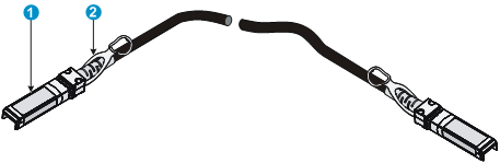
|
(1) Connector |
(2) Pull latch |
|
|
NOTE: · The fixed SFP+ ports on the switch do not support the SFP-XG-LH40-SM1550, SFP-XG-LH40-SM1550-D, SFP-XG-LH80-SM1550, and SFP-XG-LH80-SM1550-D transceiver modules. · As a best practice, use only H3C SFP/SFP+ transceiver modules and SFP/SFP+ network cables for the SFP+ ports. · The SFP/SFP+ transceiver modules and SFP/SFP+ network cables available for the switch are subject to change over time. For the most up-to-date list of SFP/SFP+ transceiver modules and SFP/SFP+ network cables, consult your H3C sales representative or technical support engineer. · For the specifications for the H3C SFP/SFP+ transceiver modules and SFP/SFP+ network cables, see H3C Transceiver Modules User Guide. |
QSFP+ port
The S5130-30S-HI, S5130-54S-HI, and S5130-54QS-HI switches provide 20G QSFP+ ports. You can install the QSFP+ network cables in Table 22 in the QSFP+ ports.
Table 22 QSFP+ network cables available for the QSFP+ ports
|
QSFP+ network cable |
Max transmission distance |
|
LSWM1QSTK0 |
1 m (3.28 ft) |
|
LSWM1QSTK1 |
3 m (9.84 ft) |
|
LSWM1QSTK2 |
5 m (16.40 ft) |
Figure 79 QSFP+ network cable
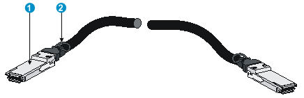
|
(1) Connector |
(2) Pull tab |
|
|
NOTE: · As a best practice, use H3C QSFP+ network cables for the QSFP+ ports on the switch. · The H3C QSFP+ network cables available for the interface cards are subject to change over time. For the most recent list of QSFP+ network cables, contact H3C Support or marketing staff. |
For more information about H3C QSFP+ network cables, see H3C Transceiver Modules User Guide.
Combo interface
The S5130-30F-HI and S5130-34C-HI switches each provide eight combo interfaces. A combo interface contains an SFP port and a 10/100/1000BASE-T autosensing Ethernet port. Only one of these two ports can operate at a time.
LEDs
System status LED
The system status LED shows the operating state of the switch.
Table 23 System status LED description
|
LED mark |
Status |
Description |
|
SYS |
Steady green |
The switch is operating correctly. |
|
Flashing green (1 Hz) |
The switch is performing power-on self test (POST). |
|
|
Steady red |
The switch has failed the POST or is faulty. |
|
|
Flashing yellow (1 Hz) |
Some ports have failed to pass POST or are faulty. |
|
|
Off |
The switch is powered off. |
Power module status LED
The S5130-30C-HI, S5130-34C-HI, S5130-54C-HI, S5130-30F-HI, S5130-30C-PWR-HI, and S5130-54C-PWR-HI switches provide two power module slots at the rear. For each power module, these switches provide a power module status LED on the front panel.
Table 24 Power module status LED description
|
LED mark |
Status |
Description |
|
PWR1 |
Steady green |
A power module is installed in power module slot 1, and the power module is outputting power correctly. |
|
Steady yellow |
A power module is installed in power module slot 1, but the power module has failed or no power is input to the power module. |
|
|
Off |
No power module is installed in power module slot 1. |
|
|
PWR2 |
Steady green |
A power module is installed in power module slot 2, and the power module is outputting power correctly. |
|
Steady yellow |
A power module is installed in power module slot 2, but the power module has failed or no power is input to the power module. |
|
|
Off |
No power module is installed in power module slot 2. |
RPS status LED
The S5130-30S-HI and S5130-54S-HI switches support RPS DC input. The RPS status LED shows the status of the RPS DC input.
Table 25 RPS status LED description
|
LED mark |
Status |
Description |
|
RPS |
Steady green |
Both the RPS DC input and the AC input are normal. |
|
Steady yellow |
The RPS DC input is normal, but the AC input is disconnected or has failed. |
|
|
Off |
The RPS DC input is abnormal or no RPS is connected. |
Port mode LED
To show more information about the switch through the port status LEDs, all S5130-HI switches except the S5130-54QS-HI switch provides a port mode LED. The port mode LED indicates the type of information that the network port LEDs are showing.
Table 26 Port mode LED description
|
LED mark |
Status |
Description |
|
Mode |
Steady green |
The port status LEDs are showing port rates. |
|
Flashing green (1 Hz) (available only for S5130-30C-PWR-HI and S5130-54C-PWR-HI switches) |
The port status LEDs are showing the status of PoE power supply on the ports. |
|
|
Flashing yellow |
The port status LEDs indicates the IRF member ID of the switch. For example, if the ports 1 to 5 are steady green, the IRF member ID of the switch is 5. |
10/100/1000BASE-T autosensing Ethernet port LED
The switch provides a status LED for each 10/100/1000BASE-T autosensing Ethernet port. The port status LED and the port mode LED indicate the operating state of the 10/100/1000BASE-T autosensing Ethernet port in conjunction.
Table 27 10/100/1000BASE-T autosensing Ethernet port LED description
|
Port mode LED (Mode) status |
Port LED status |
Description |
|
Steady green (rate mode) |
Steady green |
The port is operating at 1000 Mbps. The port LED fast flashes when the port is sending or receiving data. |
|
Steady yellow |
The port is operating at 10/100 Mbps. The port LED fast flashes when the port is sending or receiving data. |
|
|
Flashing yellow (3 Hz) |
POST has failed on the port. |
|
|
Off |
No link is present on the port. |
|
|
Flashing green (1 Hz) (PoE mode, available only for S5130-30C-PWR-HI and S5130-54C-PWR-HI switches) |
Steady green |
PoE power supply is normal. |
|
Flashing green (3 Hz) |
The device attached to the port requires power higher than the maximum or currently available PoE output power on the port. |
|
|
Steady yellow |
The port is experiencing a PoE failure. |
|
|
Flashing yellow (3 Hz) |
POST has failed on the port. |
|
|
Off |
The port is not supplying PoE power. |
|
|
Flashing yellow (IRF mode) |
Steady green |
The port status LED indicates the IRF member ID of the switch. For example, if the ports 1 to 5 are steady green, the IRF member ID of the switch is 5. |
100/1000Base-X SFP port LED
On the S5130-30F-HI and S5130-34C-HI switches, the SFP port LED and the port mode LED work in conjunction to indicate the operating status of the SFP port.
Table 28 100/1000Base-X SFP port LED description
|
Port mode LED (Mode) status |
SFP port LED status |
Description |
|
Steady green (rate mode) |
Steady green |
The port is operating at 1000 Mbps and a link is present on the port. |
|
Flashing green |
The port is sending and receiving data at 1000 Mbps. |
|
|
Steady yellow |
The port is operating at 100 Mbps and a link is present on the port. |
|
|
Flashing yellow |
The port is sending or receiving data at 100 Mbps. |
|
|
Flashing yellow (3 Hz) |
The port has failed POST. |
|
|
Off |
No link is present on the port. |
|
|
Flashing yellow (IRF mode) |
S5130-30F-HI: Steady green S5130-34C-HI: Off |
The SFP port LEDs on the switch work in conjunction to indicate the IRF member ID of the switch. For example, if the LEDs for ports 1 to 5 are steady green and the other port LEDs are off, the IRF member ID of the switch is 5. |
SFP+ port LED
Table 29 SFP+ port LED description
|
SFP+ port LED status |
Description |
|
Steady green |
The port is operating at 10 Gbps. The port LED fast flashes when the port is sending or receiving data. |
|
Steady yellow |
The port is operating at 1 Gbps. The port LED fast flashes when the port is sending or receiving data. |
|
Flashing yellow (3 Hz) |
POST has failed on the port. |
|
Off |
· No link is present on the port. · The port mode LED operates in IRF mode. · The port mode LED operates in PoE mode (for PoE switches only.) |
QSFP+ port LED
The S5130-30S-HI, S5130-54S-HI, and S5130-54QS-HI switches provide two 20G QSFP+ ports. Each QSFP+ port has a QSFP+ port LED to indicate its operating state.
Table 30 QSFP+ port LED description
|
LED status |
Description |
|
Steady green |
A transceiver module or cable has been correctly installed in the port and a link is present on the port. |
|
Flashing green |
The port is sending or receiving data. |
|
Off |
· No transceiver module or cable has been installed in the port. · No link is present on the port. · The port mode LED operates in IRF mode. |
Management Ethernet port LEDs
S5130-30C-HI&S5130-34C-HI&S5130-54C-HI&S5130-30F-HI&S5130-30C-PWR-HI&S5130-54C-PWR-HI
The S5130-30C-HI, S5130-34C-HI, S5130-54C-HI, S5130-30F-HI, S5130-30C-PWR-HI, and S5130-54C-PWR-HI switches provide an ACT/LINK LED to indicate the operating state of the management Ethernet port.
Table 31 Management Ethernet port LED description for the S5130-30C-HI, S5130-34C-HI, S5130-54C-HI, S5130-30F-HI, S5130-30C-PWR-HI, and S5130-54C-PWR-HI switches
|
Management Ethernet port LED (ACT/LINK) status |
Description |
|
Steady green |
A link is present on the port. |
|
Steady yellow |
The port is sending or receiving data |
|
Flashing yellow (3 Hz) |
The port has failed POST. |
|
Off |
No link is present on the port. |
S5130-54QS-HI
The S5130-54QS-HI switch provides one LINK LED and one ACT LED for each management Ethernet port.
Table 32 Management Ethernet port LEDs description for the S5130-54QS-HI switch
|
LED mark |
Status |
Description |
|
LINK |
Off |
The management Ethernet port is not connected. |
|
Steady green |
The management Ethernet port is operating at 10/100/1000 Mbps. |
|
|
ACT |
Off |
The management Ethernet port is not receiving or sending data. |
|
Flashing yellow |
The management Ethernet port is sending or receiving data. |
Expansion card status LED
The S5130-30C-HI, S5130-34C-HI, S5130-54C-HI, S5130-30F-HI, S5130-30C-PWR-HI, and S5130-54C-PWR-HI switches provide an expansion card slot at the rear. The expansion card status LED on the front panel indicates the operating state of the expansion card.
Table 33 Expansion card status LED description
|
LED mark |
Status |
Description |
|
SLOT |
Steady green |
The expansion card is in position and is operating correctly. |
|
Flashing yellow |
The switch does not support the card model, or the card has failed. |
|
|
Off |
The expansion card slot is empty. |
Port status LED on the expansion card
The expansion cards provide a port status LED for each port. For more information about the LEDs, see the manuals for the expansion cards.
Input status LED and output status LED on the power module
The PSR360-56A, PSR720-56A, and PSR1110-56A power modules each have an input status LED and an output status LED. For more information about the LEDs, see the manuals for the power modules.
Fan tray status LED on the fan tray
The LSPM1FANSA and LSPM1FANSB fan trays each have a fan tray status LED to indicate their operating status.
Table 34 Fan tray status LED description
|
LED mark |
Status |
Description |
|
FAN |
Steady yellow |
The fan tray is operating correctly. |
|
Flashing yellow (1 Hz) |
The fan tray is faulty. |
|
|
Off |
The fan tray has not been installed correctly or has no power input. |
Appendix D Cooling system
For correct operation of the cooling system, you must consider the site ventilation design when you plan the installation site for the switch.
The S5130-HI switches, excluding the S5130-30S-HI and S5130-54S-HI switches, use hot swappable fan trays. For correct cooling operation, install two fan trays that have the same model on one switch. For more information about available fan trays for an S5130-HI switch, see Table 35.
The S5130-30S-HI and S5130-54S-HI switches use fixed fan trays and left-to-right aisles for air ventilation. Ambient air flows in through the air vents in the left side panel, and exhausts through the air vents in the right side panel.
|
Switch model |
Available fan tray |
Airflow |
|
S5130-30C-HI S5130-30F-HI S5130-34C-HI S5130-54C-HI S5130-30C-PWR-HI S5130-54C-PWR-HI |
LSPM1FANSA |
Ambient air flows in through the air vents in the power module panel, and exhausts through the air vents in the port side, left side, and right side panels. |
|
LSPM1FANSB |
Ambient air flows in through the air vents in the port side, left side, and right side panels, and exhausts through the air vents in the power module panel. |
|
|
S5130-54QS-HI |
LSPM1FANSA |
Ambient air flows in through the air vents in the power module panel, and exhausts through the air vents in the port side panel. |
|
LSPM1FANSB |
Ambient air flows in through the air vents in the port side panel, and exhausts through the air vents in the power module panel. |
Figure 80 Airflow through the S5130-30S-HI switch
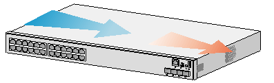
Figure 81 Airflow through the S5130-54C-HI switch
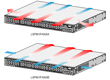
Figure 82 Airflow through the S5130-54QS-HI switch