- Table of Contents
- Related Documents
-
| Title | Size | Download |
|---|---|---|
| 01-Text | 1.30 MB |
Temperature and humidity requirements
Determining the installation position
Mounting the AP by using an articulating arm
Verifying the network connection
Appendix A Technical specifications
Preparing for installation
Safety recommendations
|
|
WARNING! Only qualified personnel can install and remove the AP and its accessories. You must read all safety instructions before installation and operation. |
To avoid possible bodily injury and equipment damage, read the following safety recommendations before installing the AP. Note that the recommendations do not cover every possible hazardous condition.
· Take adequate safety measures to avoid bodily injury and device damage.
· Place the AP in a dry and flat location and take anti-slip measures.
· Keep the AP clean and dust-free.
· Do not place the AP in a moist area and avoid liquid intrusion.
· Keep the AP and installation tools away from walkways.
Temperature and humidity requirements
Table 1 Temperature and humidity requirements
|
Specification |
|
|
Operating temperature |
0°C to 45°C (32°F to 113°F) |
|
Storage temperature |
–40°C to +70°C (–40°F to +158°F) |
|
Operating humidity |
5% RH to 95% RH, non-condensing |
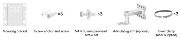
Installation accessories
Figure 1 Installation accessories
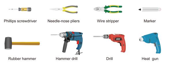
Installation tools
When installing the AP, you might need the following tools. Prepare the installation tools as required.
Figure 2 Installation tools
Installing the AP
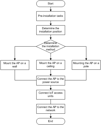
Installation flowchart
Figure 3 Installation flowchart
Pre-installation tasks
Before installing the AP, perform the following tasks:
· Connect the AP to a power source and the network. Examine the LEDs to verify that the AP operates correctly. For information about AP LEDs, see "Appendix B LEDs and ports."
· Record the MAC address and serial number at the rear of the AP for future use.
· Make sure you have completed cabling at the installation site.
Determining the installation position
Determine the installation position by observing the following principles:
· Few obstacles such as wall exist between the AP and clients.
· The AP is far away from electronic devices (such as microwave oven) that might generate radio frequency (RF) noise.
· The AP does not hinder people’s daily work and life.
· The place is dry, without any leakage, dripping, or dew.
Mounting the AP
The AP can be installed only indoors. You can directly mount the AP on a wall or a ceiling, or mount the AP on a wall or on a pole through an articulating arm.
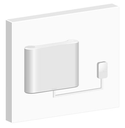
Mounting the AP on a wall
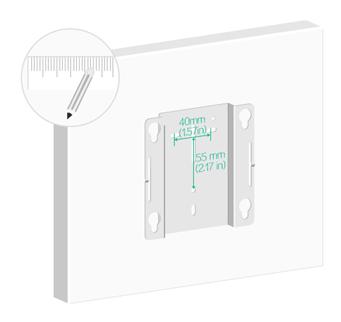
1. Mark the installation holes on the wall by using the mounting bracket, as shown in Figure 4.
Figure 4 Marking installation holes on the wall
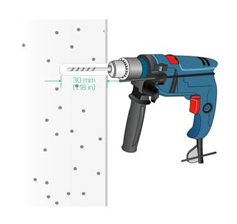
2. Drill three holes with a diameter of 6 mm (0.24 in) and a depth of 30 mm (1.18 in) in the marked locations, as shown in Figure 5.
Figure 5 Drilling holes in the wall
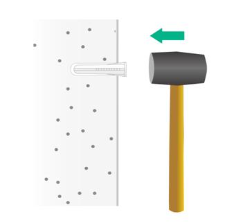
3. Insert a screw anchor into each hole, and tap the screw anchor by using a rubber hammer until it is all flush with the wall surface, as shown in Figure 6.
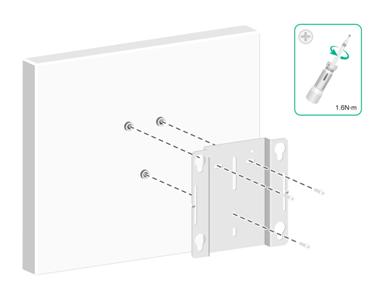
4. Align the installation holes in the mounting bracket with the anchors and thread screws through the installation holes into the screw anchors. Adjust the position of the mounting bracket and fasten the screws.
Figure 7 Attaching the mounting bracket to the wall
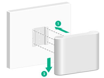
5. Position the four pegs on the AP rear into the keyed slots in the bracket, and then slide the AP until you feel it snaps into place.
Figure 8 Attaching the AP to the wall/ceiling bracket
Mounting the AP on a ceiling
|
|
CAUTION: The ceiling for installing the AP must be less than 18 mm (0.71 in) in thickness, and can bear a load of 5 kg (11.02 lb). If the ceiling is not strong enough, use boards to reinforce the ceiling as a best practice. |
To mount the AP on a ceiling:
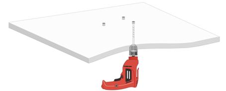
1. Remove the ceiling tile and use the mounting bracket to mark the installation holes on the ceiling tile.
Figure 9 Marking the installation holes on the ceiling tile

2. Drill three holes with a diameter of 6 mm (0.24 in) in the marked positions.
Figure 10 Drilling holes in the ceiling
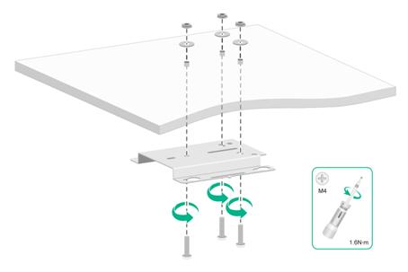
3. Thread the pan-head screws through the installation holes in the mounting bracket and into the holes in the ceiling. Fasten washers and nuts at the other side of the ceiling to attach the mounting bracket to the ceiling.
Figure 11 Attaching the mounting bracket to the ceiling
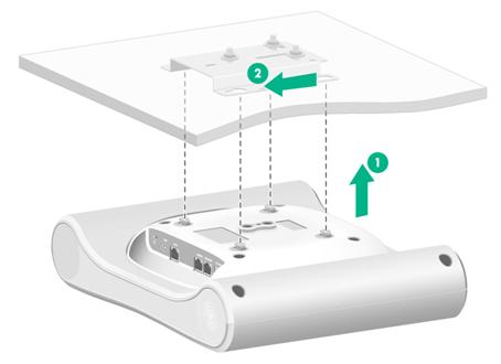
4. Position the four pegs on the AP rear into the keyed slots in the bracket, and then slide the AP until you feel it snaps into place.
Figure 12 Attaching the AP to the mounting bracket
Mounting the AP by using an articulating arm
The AP does not come with an articulating arm. Purchase one as needed.
The AP does not come with a band clamp for pole mounting. Prepare one yourself as needed.
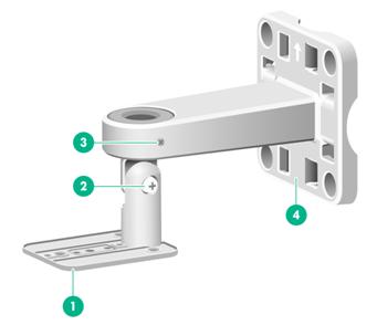
|
(1) Articulating mount |
(2) Articulating mount screw |
(3) Mount plate screw |
(4) Mount plate |
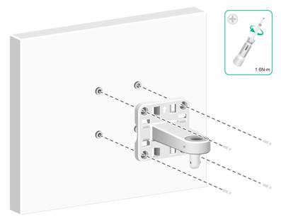
Installing the mount plate on a wall
1. Use the mount plate to mark four installation holes on the wall.
2. Drill four holes with a diameter of 6 mm (0.24 in) in the marked positions, as shown in Figure 5.
3. Thread a screw anchor into each hole, and tap the screw anchor by using a rubber hammer until it is all flush with the wall surface, as shown in Figure 6.
4. Align the installation holes in the mount plate with the anchors and thread screws through the installation holes into the screw anchors. Adjust the position of the mount plate and fasten the screws, as shown in Figure 14.
Figure 14 Installing the mount plate on a wall
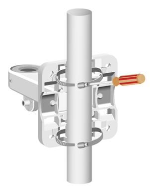
Installing the mount plate on a pole
1. Loosen the captive screw on a band clamp, thread the band clamp through the slots in the mount plate, wrap the band clamp around the pole, and then fasten the screw. Attach the other band clamp to the pole in the same way this band clamp is attached to secure the mount plate to the pole.
|
|
NOTE: You can attach the mount plate to a pole with a diameter of 50 to 80 mm (1.97 to 3.15 in). |
Figure 15 Installing the mount plate on a pole (horizontal pole)
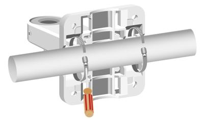
Figure 16 Installing the mount plate on a pole (vertical pole)
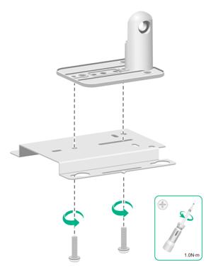
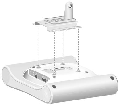
Attaching the AP to the mount plate
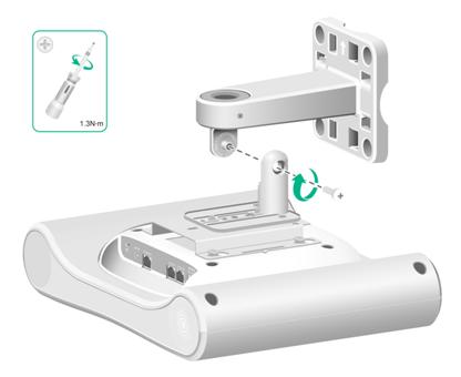
1. Use M4 screws to attach the articulating mount to the mounting bracket.
Figure 17 Attaching the articulating mount to the mounting bracket
2. Position the four pegs on the AP rear into the keyed slots in the bracket, and then slide the AP until you feel it snaps into place.
Figure 18 Attaching the AP to the mounting bracket
3. Align the arm on the articulating mount with the joint on the mount plate, and then use an M5 screw to attach the articulating mount to the mount plate. Adjust the AP to the desired elevation angle, and then fasten the screw.
Figure 19 Attaching the articulating mount to the mount plate
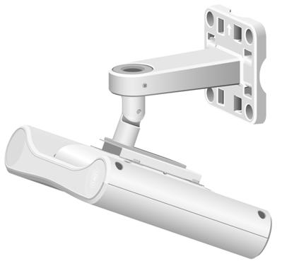
4. Adjust the AP to the desired azimuth angle, and then fasten the screws on both sides of the mount plate.
Make sure the ports on the AP face downward, as shown in Figure 21.
Figure 20 Adjusting the AP to the desired azimuth angle
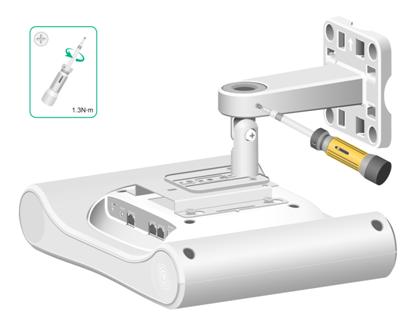
Figure 21 Installation completed
Powering on the AP
You can supply power to the AP by using a power adapter or through PoE.
Prerequisites
Make sure the local power source or PSE is reliably grounded.
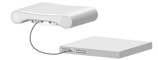
Connecting the PoE power supply
Use an Ethernet cable to connect port GE1/PoE+ on the AP to a port on a switch that supports PoE.
Figure 22 Connecting the PoE power supply
Connecting a power adapter
Use a power adapter to connect the AP to a local AC/DC power source.
|
|
NOTE: The AP does not come with a power adapter. Purchase one as needed. |
Figure 23 Connecting the AP to a local power source by using a power adapter

Table 2 Power adapter specifications
|
Item |
Specifications |
|
Input |
100 to 240 VAC |
|
Output |
+54 V |
Verifying the connection
After connecting the AP to a power source, examine the AP LED to verify the connection. For more information about the AP LED, see "Appendix B LEDs and ports."
Connecting IoT access units
To connect an access unit to the AP, you can use a straight-through or crossover Ethernet cable of Category 5e or higher. As a best practice, use a straight-through Ethernet cable.
Only port GE2/IoT supports connecting IoT access units.
Figure 24 Connecting IoT access units to the AP
Verifying the network connection
All settings of the AP (in fit mode) are configured on the AC. Use the display wlan ap all command on the AC that connects to the AP to view AP status. If the AP status is R/M, the AP has been connected to the network.
Total number of APs: 1
Total number of connected APs: 1
Total number of connected manual APs: 1
Total number of connected auto APs: 0
Total number of connected common APs: 1
Total number of connected WTUs: 0
Total number of inside APs: 0
Maximum supported APs: 3072
Remaining APs: 3071
Total AP licenses: 128
Remaining AP licenses: 127
Sync AP licenses: 0
AP information
State : I = Idle, J = Join, JA = JoinAck, IL = ImageLoad
C = Config, DC = DataCheck, R = Run M = Master, B = Backup
AP name APID State Model Serial ID
ap1 1 R WA5530i 219801A1TF818BE0000Y
Appendix A Technical specifications
Table 3 Technical specifications
|
Item |
Specification |
|
Dimensions (H × W × D) |
55.5 × 255 × 312 mm (2.19 × 10.04 × 12.28 in) |
|
Weight |
2.3 kg (5.07 lb) |
|
Radios |
Three |
|
Antenna (built-in) |
· 2.4 G: 9 dBi peak gain · 5.2 G: 9 dBi peak gain · 5.8 G: 9 dBi peak gain |
|
System power consumption |
30 W |
|
Protocol compliance |
· IEEE802.11a/b/g/n/ac Wave 2 · 802.3at/af |
Appendix B LEDs and ports
LEDs
|
Status |
Description |
|
|
N/A |
Off |
No power is present or the LED has been disabled. |
|
Amber |
Steady on |
The AP is initializing or an initialization error has occurred. |
|
Flashing at 1 Hz |
No radios have been detected. |
|
|
Flashing at 2 Hz |
The Ethernet interfaces have not started up and no mesh links are established. |
|
|
Green |
Steady on |
The AP has registered on an AC, but does not have any associated clients. |
|
Flashing at 0.5 Hz |
The AP has started up, but has not registered on an AC. |
|
|
Flashing at 1 Hz |
Only the 2.4 G radio has associated clients. |
|
|
Flashing at 2 Hz |
The AP is upgrading its image. |
|
|
Blue |
Flashing at 1 Hz |
Only the 5 G radio has associated clients. |
|
Alternating between green and blue at 1 Hz |
Both the 2.4 G and 5 G radios have associated clients. |
|
Ports
The AP provides the following ports:
· One console port.
· Two GE ports.
· One power port.
The AP also has a reset button and a security slot. The security slot is 7 × 3 mm (0.28 × 0.12 in) in size.
Figure 25 Ports on the AP
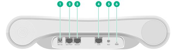
|
(1) Power port |
(2) and (3) 10/100/1000 Mbps Ethernet ports |
(4) Console port |
|
(5) Reset button |
(6) Security slot |
|
Table 5 Port description
|
Port |
Standards and protocols |
Description |
|
Console port |
RS/EIA-232 |
Used by maintenance personnel for device configuration and management only. |
|
GE1/PoE+ |
· IEEE802.3 · IEEE802.3u · IEEE802.3af · IEEE802.3at |
Used for connecting the AP to an uplink device for Internet or MAN access. It can also receive PoE power from the uplink device. It is represented by interface number GE1/0/1 in the MAP file and gigabitethernet 1 for configuration on the AC. |
|
GE2/IoT |
· IEEE802.3 · IEEE802.3u |
An IoT interface, used for connecting a downlink T300M-X or T300M-B IoT access unit to the AP. It is represented by interface number GE1/0/2 in the MAP file and gigabitethernet 2 for configuration on the AC. |
|
48V DC |
N/A |
Used for receiving +48 VDC power from the local power source. |
