- Table of Contents
- Related Documents
-
01-Text
Download Book (2.19 MB)AAA implementation on the device
AAA configuration considerations and task list
Configuring AAA methods for ISP domains
Configuring ISP domain attributes
Configuring authentication methods for an ISP domain
Configuring authorization methods for an ISP domain
Configuring accounting methods for an ISP domain
Configuring the RADIUS session-control feature
Configuring the RADIUS DAS feature
Changing the DSCP priority for RADIUS packets
Configuring the RADIUS attribute translation feature
Setting the maximum number of concurrent login users
Displaying and maintaining AAA
AAA for SSH users by an HWTACACS server
Local authentication, HWTACACS authorization, and RADIUS accounting for SSH users
Authentication and authorization for SSH users by a RADIUS server
RADIUS packet delivery failure
Password updating and expiration
Password not displayed in any form
Password control configuration task list
Setting global password control parameters
Setting user group password control parameters
Setting local user password control parameters
Setting super password control parameters
Displaying and maintaining password control
Password control configuration example
Displaying and maintaining keychain··
Keychain configuration example
Distributing a local host public key
Configuring a peer host public key
Importing a peer host public key from a public key file
Entering a peer host public key
Displaying and maintaining public keys
Examples of public key management
Example for entering a peer host public key
Example for importing a public key from a public key file
Configuring the device as an SSH server
SSH server configuration task list
Configuring the user lines for SSH login··
Configuring a client's host public key
Configuring the SSH management parameters
Configuring the device as an Stelnet client
Stelnet client configuration task list
Specifying the source IP address for SSH packets
Establishing a connection to an Stelnet server
Configuring the device as an SFTP client
SFTP client configuration task list
Specifying the source IP address for SFTP packets
Establishing a connection to an SFTP server
Terminating the connection with the SFTP server
Configuring the device as an SCP client
SCP client configuration task list
Establishing a connection to an SCP server
Specifying algorithms for SSH2
Specifying key exchange algorithms for SSH2
Specifying public key algorithms for SSH2·
Specifying encryption algorithms for SSH2·
Specifying MAC algorithms for SSH2·
Displaying and maintaining SSH
Stelnet configuration examples
Password authentication enabled Stelnet server configuration example
Publickey authentication enabled Stelnet server configuration example
Password authentication enabled Stelnet client configuration example
Publickey authentication enabled Stelnet client configuration example
Password authentication enabled SFTP server configuration example
Publickey authentication enabled SFTP client configuration example
SCP configuration example with password authentication
NETCONF over SSH configuration example with password authentication
Configuring attack detection and prevention
Attacks that the device can prevent
Attack detection and prevention configuration task list
Configuring an attack defense policy
Creating an attack defense policy
Configuring a single-packet attack defense policy
Configuring a scanning attack defense policy
Configuring a flood attack defense policy
Configuring attack detection exemption··
Applying an attack defense policy to the device
Enabling log non-aggregation for single-packet attack events
Configuring TCP fragment attack prevention
Displaying and maintaining attack detection and prevention
Attack detection and prevention configuration examples
Attack defense policy device application configuration example
Configuring TCP attack prevention
Configuring Naptha attack prevention
Configuring the IPv4SG feature
Enabling IPv4SG on an interface
Configuring a static IPv4SG binding
Configuring the IPv6SG feature
Enabling IPv6SG on an interface
Configuring a static IPv6SG binding
Displaying and maintaining IPSG
Static IPv4SG configuration example
Dynamic IPv4SG using DHCP snooping configuration example
Dynamic IPv4SG using DHCP relay agent configuration example
Static IPv6SG configuration example
Dynamic IPv6SG using DHCPv6 relay agent configuration example
Configuring ARP attack protection
ARP attack protection configuration task list
Configuring unresolvable IP attack protection
Configuring ARP source suppression
Configuring ARP blackhole routing
Displaying and maintaining unresolvable IP attack protection
Configuring ARP packet rate limit
Configuring source MAC-based ARP attack detection
Displaying and maintaining source MAC-based ARP attack detection
Configuring ARP packet source MAC consistency check
Configuring ARP active acknowledgement
Configuration example (on a DHCP server)
Configuration example (on a DHCP relay agent)
Configuring ARP attack detection
Configuring user validity check
Configuring ARP packet validity check
Configuring ARP restricted forwarding
Enabling ARP attack detection logging
Displaying and maintaining ARP attack detection
User validity check and ARP packet validity check configuration example
ARP restricted forwarding configuration example
Configuring ARP scanning and fixed ARP
Configuration restrictions and guidelines
Configuring ARP gateway protection
Enabling source MAC consistency check for ND messages
Displaying and maintaining uRPF
Interface-specific uRPF configuration example
Global uRPF configuration example
Configuration restrictions and guidelines
Configuration changes in FIPS mode
Displaying and maintaining FIPS
Entering FIPS mode through automatic reboot
Entering FIPS mode through manual reboot
Exiting FIPS mode through automatic reboot
Exiting FIPS mode through manual reboot
Configuring AAA
Overview
Authentication, Authorization, and Accounting (AAA) provides a uniform framework for implementing network access management. This feature specifies the following security functions:
· Authentication—Identifies users and verifies their validity.
· Authorization—Grants different users different rights, and controls the users' access to resources and services. For example, you can permit office users to read and print files and prevent guests from accessing files on the device.
· Accounting—Records network usage details of users, including the service type, start time, and traffic. This function enables time-based and traffic-based charging and user behavior auditing.
AAA uses a client/server model. The client runs on the access device, or the network access server (NAS), which authenticates user identities and controls user access. The server maintains user information centrally. See Figure 1.
Figure 1 AAA network diagram
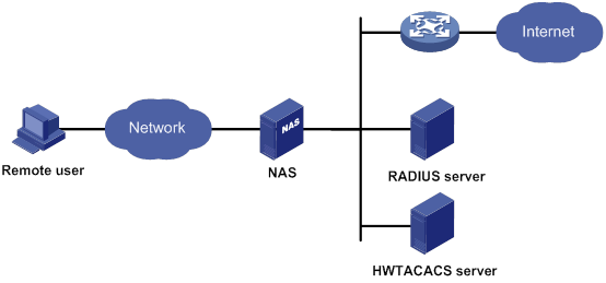
To access networks or resources beyond the NAS, a user sends its identity information to the NAS. The NAS transparently passes the user information to AAA servers and waits for the authentication, authorization, and accounting result. Based on the result, the NAS determines whether to permit or deny the access request.
AAA has various implementations, including RADIUS and HWTACACS. RADIUS is most often used.
The network in Figure 1 has one RADIUS server and one HWTACACS server. You can use different servers to implement different security functions. For example, you can use the HWTACACS server for authentication and authorization, and use the RADIUS server for accounting.
You can choose the security functions provided by AAA as needed. For example, if your company wants employees to be authenticated before they access specific resources, you would deploy an authentication server. If network usage information is needed, you would also configure an accounting server.
The device performs dynamic password authentication.
RADIUS
Remote Authentication Dial-In User Service (RADIUS) is a distributed information interaction protocol that uses a client/server model. The protocol can protect networks against unauthorized access and is often used in network environments that require both high security and remote user access.
The RADIUS authorization process is combined with the RADIUS authentication process, and user authorization information is piggybacked in authentication responses. RADIUS uses UDP port 1812 for authentication and UDP port 1813 for accounting.
RADIUS was originally designed for dial-in user access, and has been extended to support additional access methods, such as Ethernet and ADSL.
Client/server model
The RADIUS client runs on the NASs located throughout the network. It passes user information to RADIUS servers and acts on the responses to, for example, reject or accept user access requests.
The RADIUS server runs on the computer or workstation at the network center and maintains information related to user authentication and network service access.
The RADIUS server operates using the following process:
1. Receives authentication, authorization, and accounting requests from RADIUS clients.
2. Performs user authentication, authorization, or accounting.
3. Returns user access control information (for example, rejecting or accepting the user access request) to the clients.
The RADIUS server can also act as the client of another RADIUS server to provide authentication proxy services.
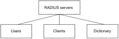
The RADIUS server maintains the following databases:
· Users—Stores user information, such as the usernames, passwords, applied protocols, and IP addresses.
· Clients—Stores information about RADIUS clients, such as shared keys and IP addresses.
· Dictionary—Stores RADIUS protocol attributes and their values.
Figure 2 RADIUS server databases
Information exchange security mechanism
The RADIUS client and server exchange information between them with the help of shared keys, which are preconfigured on the client and server. A RADIUS packet has a 16-byte field called Authenticator. This field includes a signature generated by using the MD5 algorithm, the shared key, and some other information. The receiver of the packet verifies the signature and accepts the packet only when the signature is correct. This mechanism ensures the security of information exchanged between the RADIUS client and server.
The shared keys are also used to encrypt user passwords that are included in RADIUS packets.
User authentication methods
The RADIUS server supports multiple user authentication methods, such as PAP, CHAP, and EAP.
Basic RADIUS packet exchange process
Figure 3 illustrates the interactions between a user host, the RADIUS client, and the RADIUS server.
Figure 3 Basic RADIUS packet exchange process

RADIUS uses in the following workflow:
1. The host sends a connection request that includes the user's username and password to the RADIUS client.
2. The RADIUS client sends an authentication request (Access-Request) to the RADIUS server. The request includes the user's password, which has been processed by the MD5 algorithm and shared key.
3. The RADIUS server authenticates the username and password. If the authentication succeeds, the server sends back an Access-Accept packet that contains the user's authorization information. If the authentication fails, the server returns an Access-Reject packet.
4. The RADIUS client permits or denies the user according to the authentication result. If the result permits the user, the RADIUS client sends a start-accounting request (Accounting-Request) packet to the RADIUS server.
5. The RADIUS server returns an acknowledgment (Accounting-Response) packet and starts accounting.
6. The user accesses the network resources.
7. The host requests the RADIUS client to tear down the connection.
8. The RADIUS client sends a stop-accounting request (Accounting-Request) packet to the RADIUS server.
9. The RADIUS server returns an acknowledgment (Accounting-Response) and stops accounting for the user.
10. The RADIUS client notifies the user of the termination.
RADIUS packet format
RADIUS uses UDP to transmit packets. The protocol also uses a series of mechanisms to ensure smooth packet exchange between the RADIUS server and the client. These mechanisms include the timer mechanism, the retransmission mechanism, and the backup server mechanism.
Figure 4 RADIUS packet format

Descriptions of the fields are as follows:
· The Code field (1 byte long) indicates the type of the RADIUS packet. Table 1 gives the main values and their meanings.
Table 1 Main values of the Code field
|
Code |
Packet type |
Description |
|
1 |
Access-Request |
From the client to the server. A packet of this type includes user information for the server to authenticate the user. It must contain the User-Name attribute and can optionally contain the attributes of NAS-IP-Address, User-Password, and NAS-Port. |
|
2 |
Access-Accept |
From the server to the client. If all attribute values included in the Access-Request are acceptable, the authentication succeeds, and the server sends an Access-Accept response. |
|
3 |
Access-Reject |
From the server to the client. If any attribute value included in the Access-Request is unacceptable, the authentication fails, and the server sends an Access-Reject response. |
|
4 |
Accounting-Request |
From the client to the server. A packet of this type includes user information for the server to start or stop accounting for the user. The Acct-Status-Type attribute in the packet indicates whether to start or stop accounting. |
|
5 |
Accounting-Response |
From the server to the client. The server sends a packet of this type to notify the client that it has received the Accounting-Request and has successfully recorded the accounting information. |
· The Identifier field (1 byte long) is used to match response packets with request packets and to detect duplicate request packets. The request and response packets of the same exchange process for the same purpose (such as authentication or accounting) have the same identifier.
· The Length field (2 bytes long) indicates the length of the entire packet (in bytes), including the Code, Identifier, Length, Authenticator, and Attributes fields. Bytes beyond this length are considered padding and are ignored by the receiver. If the length of a received packet is less than this length, the packet is dropped.
· The Authenticator field (16 bytes long) is used to authenticate responses from the RADIUS server and to encrypt user passwords. There are two types of authenticators: request authenticator and response authenticator.
· The Attributes field (variable in length) includes authentication, authorization, and accounting information. This field can contain multiple attributes, each with the following subfields:
? Type—Type of the attribute.
? Length—Length of the attribute in bytes, including the Type, Length, and Value subfields.
? Value—Value of the attribute. Its format and content depend on the Type subfield.
Commonly used RADIUS attributes are defined in RFC 2865, RFC 2866, RFC 2867, and RFC 2868. For more information, see "Commonly used standard RADIUS attributes."
Table 2 Commonly used RADIUS attributes
|
No. |
Attribute |
No. |
Attribute |
|
1 |
User-Name |
45 |
Acct-Authentic |
|
2 |
User-Password |
46 |
Acct-Session-Time |
|
3 |
CHAP-Password |
47 |
Acct-Input-Packets |
|
4 |
NAS-IP-Address |
48 |
Acct-Output-Packets |
|
5 |
NAS-Port |
49 |
Acct-Terminate-Cause |
|
6 |
Service-Type |
50 |
Acct-Multi-Session-Id |
|
7 |
Framed-Protocol |
51 |
Acct-Link-Count |
|
8 |
Framed-IP-Address |
52 |
Acct-Input-Gigawords |
|
9 |
Framed-IP-Netmask |
53 |
Acct-Output-Gigawords |
|
10 |
Framed-Routing |
54 |
(unassigned) |
|
11 |
Filter-ID |
55 |
Event-Timestamp |
|
12 |
Framed-MTU |
56-59 |
(unassigned) |
|
13 |
Framed-Compression |
60 |
CHAP-Challenge |
|
14 |
Login-IP-Host |
61 |
NAS-Port-Type |
|
15 |
Login-Service |
62 |
Port-Limit |
|
16 |
Login-TCP-Port |
63 |
Login-LAT-Port |
|
17 |
(unassigned) |
64 |
Tunnel-Type |
|
18 |
Reply-Message |
65 |
Tunnel-Medium-Type |
|
19 |
Callback-Number |
66 |
Tunnel-Client-Endpoint |
|
20 |
Callback-ID |
67 |
Tunnel-Server-Endpoint |
|
21 |
(unassigned) |
68 |
Acct-Tunnel-Connection |
|
22 |
Framed-Route |
69 |
Tunnel-Password |
|
23 |
Framed-IPX-Network |
70 |
ARAP-Password |
|
24 |
State |
71 |
ARAP-Features |
|
25 |
Class |
72 |
ARAP-Zone-Access |
|
26 |
Vendor-Specific |
73 |
ARAP-Security |
|
27 |
Session-Timeout |
74 |
ARAP-Security-Data |
|
28 |
Idle-Timeout |
75 |
Password-Retry |
|
29 |
Termination-Action |
76 |
Prompt |
|
30 |
Called-Station-Id |
77 |
Connect-Info |
|
31 |
Calling-Station-Id |
78 |
Configuration-Token |
|
32 |
NAS-Identifier |
79 |
EAP-Message |
|
33 |
Proxy-State |
80 |
Message-Authenticator |
|
34 |
Login-LAT-Service |
81 |
Tunnel-Private-Group-ID |
|
35 |
Login-LAT-Node |
82 |
Tunnel-Assignment-id |
|
36 |
Login-LAT-Group |
83 |
Tunnel-Preference |
|
37 |
Framed-AppleTalk-Link |
84 |
ARAP-Challenge-Response |
|
38 |
Framed-AppleTalk-Network |
85 |
Acct-Interim-Interval |
|
39 |
Framed-AppleTalk-Zone |
86 |
Acct-Tunnel-Packets-Lost |
|
40 |
Acct-Status-Type |
87 |
NAS-Port-Id |
|
41 |
Acct-Delay-Time |
88 |
Framed-Pool |
|
42 |
Acct-Input-Octets |
89 |
(unassigned) |
|
43 |
Acct-Output-Octets |
90 |
Tunnel-Client-Auth-id |
|
44 |
Acct-Session-Id |
91 |
Tunnel-Server-Auth-id |
Extended RADIUS attributes
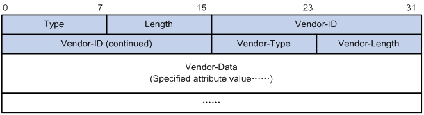
The RADIUS protocol features excellent extensibility. The Vendor-Specific attribute (attribute 26) allows a vendor to define extended attributes. The extended attributes can implement functions that the standard RADIUS protocol does not provide.
A vendor can encapsulate multiple subattributes in the TLV format in attribute 26 to provide extended functions. As shown in Figure 5, a subattribute encapsulated in attribute 26 consists of the following parts:
· Vendor-ID—ID of the vendor. The most significant byte is 0. The other three bytes contains a code compliant to RFC 1700.
· Vendor-Type—Type of the subattribute.
· Vendor-Length—Length of the subattribute.
· Vendor-Data—Contents of the subattribute.
The device supports RADIUS subattributes with a vendor ID of 25506. For more information, see "Proprietary RADIUS subattributes (vendor ID 25506)."
Figure 5 Format of attribute 26
HWTACACS
HWTACACS typically provides AAA services for PPP, VPDN, and terminal users. In a typical HWTACACS scenario, terminal users need to log in to the NAS. Working as the HWTACACS client, the NAS sends users' usernames and passwords to the HWTACACS server for authentication. After passing authentication and obtaining authorized rights, a user logs in to the device and performs operations. The HWTACACS server records the operations that each user performs.
Differences between HWTACACS and RADIUS
HWTACACS and RADIUS have many features in common, such as using a client/server model, using shared keys for data encryption, and providing flexibility and scalability. Table 3 lists the primary differences between HWTACACS and RADIUS.
Table 3 Primary differences between HWTACACS and RADIUS
|
HWTACACS |
RADIUS |
|
Uses TCP, which provides reliable network transmission. |
Uses UDP, which provides high transport efficiency. |
|
Encrypts the entire packet except for the HWTACACS header. |
Encrypts only the user password field in an authentication packet. |
|
Protocol packets are complicated and authorization is independent of authentication. Authentication and authorization can be deployed on different HWTACACS servers. |
Protocol packets are simple and the authorization process is combined with the authentication process. |
|
Supports authorization of configuration commands. Access to commands depends on both the user's roles and authorization. A user can use only commands that are permitted by the user roles and authorized by the HWTACACS server. |
Does not support authorization of configuration commands. Access to commands solely depends on the user's roles. For more information about user roles, see Fundamentals Configuration Guide. |
Basic HWTACACS packet exchange process
Figure 6 describes how HWTACACS performs user authentication, authorization, and accounting for a Telnet user.
Figure 6 Basic HWTACACS packet exchange process for a Telnet user
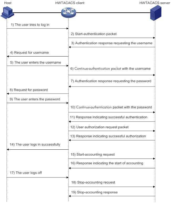
HWTACACS operates using in the following workflow:
1. A Telnet user sends an access request to the HWTACACS client.
2. The HWTACACS client sends a start-authentication packet to the HWTACACS server when it receives the request.
3. The HWTACACS server sends back an authentication response to request the username.
4. Upon receiving the response, the HWTACACS client asks the user for the username.
5. The user enters the username.
6. After receiving the username from the user, the HWTACACS client sends the server a continue-authentication packet that includes the username.
7. The HWTACACS server sends back an authentication response to request the login password.
8. Upon receipt of the response, the HWTACACS client prompts the user for the login password.
9. The user enters the password.
10. After receiving the login password, the HWTACACS client sends the HWTACACS server a continue-authentication packet that includes the login password.
11. If the authentication succeeds, the HWTACACS server sends back an authentication response to indicate that the user has passed authentication.
12. The HWTACACS client sends a user authorization request packet to the HWTACACS server.
13. If the authorization succeeds, the HWTACACS server sends back an authorization response, indicating that the user is now authorized.
14. Knowing that the user is now authorized, the HWTACACS client pushes its CLI to the user and permits the user to log in.
15. The HWTACACS client sends a start-accounting request to the HWTACACS server.
16. The HWTACACS server sends back an accounting response, indicating that it has received the start-accounting request.
17. The user logs off.
18. The HWTACACS client sends a stop-accounting request to the HWTACACS server.
19. The HWTACACS server sends back a stop-accounting response, indicating that the stop-accounting request has been received.
AAA implementation on the device
This section describes AAA user management and methods.
User management based on ISP domains and user access types
AAA manages users based on the users' ISP domains and access types.
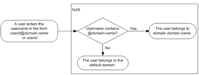
On a NAS, each user belongs to one ISP domain. The NAS determines the ISP domain to which a user belongs based on the username entered by the user at login.
Figure 7 Determining the ISP domain for a user by username
AAA manages users in the same ISP domain based on the users' access types. The device supports the following user access types:
· Login—Login users include SSH, Telnet, FTP, and terminal users that log in to the device. Terminal users can access through a console port.
· HTTP or HTTPS—Users log in to the device through HTTP or HTTPS.
AAA methods
AAA supports configuring different authentication, authorization, and accounting methods for different types of users in an ISP domain. The NAS determines the ISP domain and access type of a user. The NAS also uses the methods configured for the access type in the domain to control the user's access.
AAA also supports configuring a set of default methods for an ISP domain. These default methods are applied to users for which no AAA methods are configured.
The device supports the following authentication methods:
· No authentication—This method trusts all users and does not perform authentication. For security purposes, do not use this method.
· Local authentication—The NAS authenticates users by itself, based on the locally configured user information including the usernames, passwords, and attributes. Local authentication allows high speed and low cost, but the amount of information that can be stored is limited by the size of the storage space.
· Remote authentication—The NAS works with a RADIUS or HWTACACS server to authenticate users. The server manages user information in a centralized manner. Remote authentication provides high capacity, reliable, and centralized authentication services for multiple NASs. You can configure backup methods to be used when the remote server is not available.
The device supports the following authorization methods:
· No authorization—The NAS performs no authorization exchange. The following default authorization information applies after users pass authentication:
? Login users obtain the level-0 user role. For more information about the level-0 user role, see RBAC configuration in Fundamentals Configuration Guide.
? The working directory for FTP, SFTP, and SCP login users is the root directory of the NAS. However, the users do not have permission to access the root directory.
· Local authorization—The NAS performs authorization according to the user attributes locally configured for users.
· Remote authorization—The NAS works with a RADIUS or HWTACACS server to authorize users. RADIUS authorization is bound with RADIUS authentication. RADIUS authorization can work only after RADIUS authentication is successful, and the authorization information is included in the Access-Accept packet. HWTACACS authorization is separate from HWTACACS authentication, and the authorization information is included in the authorization response after successful authentication. You can configure backup methods to be used when the remote server is not available.
The device supports the following accounting methods:
· No accounting—The NAS does not perform accounting for the users.
· Local accounting—Local accounting is implemented on the NAS. It counts and controls the number of concurrent users that use the same local user account, but does not provide statistics for charging.
· Remote accounting—The NAS works with a RADIUS server or HWTACACS server for accounting. You can configure backup methods to be used when the remote server is not available.
In addition, the device provides the following login services to enhance device security:
· Command authorization—Enables the NAS to let the authorization server determine whether a command entered by a login user is permitted. Login users can execute only commands permitted by the authorization server. For more information about command authorization, see Fundamentals Configuration Guide.
· Command accounting—When command authorization is disabled, command accounting enables the accounting server to record all valid commands executed on the device. When command authorization is enabled, command accounting enables the accounting server to record all authorized commands. For more information about command accounting, see Fundamentals Configuration Guide.
· User role authentication—Authenticates each user that wants to obtain another user role without logging out or getting disconnected. For more information about user role authentication, see Fundamentals Configuration Guide.
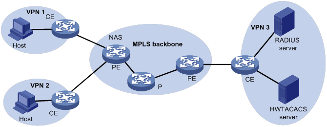
AAA for MPLS L3VPNs
You can deploy AAA across VPNs in an MPLS L3VPN scenario where clients in different VPNs are centrally authenticated. The deployment enables forwarding of RADIUS and HWTACACS packets across MPLS VPNs. For example, as shown in Figure 8, you can deploy AAA across the VPNs. The left PE connects the user private networks to the MPLS backbone and acts as a NAS. The NAS transparently delivers the AAA packets of private users in VPN 1 and VPN 2 to the AAA servers in VPN 3 for centralized authentication. The servers process authentication packets separately for private users from different VPNs.
Protocols and standards
· RFC 2865, Remote Authentication Dial In User Service (RADIUS)
· RFC 2866, RADIUS Accounting
· RFC 2867, RADIUS Accounting Modifications for Tunnel Protocol Support
· RFC 2868, RADIUS Attributes for Tunnel Protocol Support
· RFC 2869, RADIUS Extensions
· RFC 5176, Dynamic Authorization Extensions to Remote Authentication Dial In User Service (RADIUS)
· RFC 1492, An Access Control Protocol, Sometimes Called TACACS
RADIUS attributes
Commonly used standard RADIUS attributes
|
No. |
Attribute |
Description |
|
1 |
User-Name |
Name of the user to be authenticated. |
|
2 |
User-Password |
User password for PAP authentication, only present in Access-Request packets when PAP authentication is used. |
|
3 |
CHAP-Password |
Digest of the user password for CHAP authentication, only present in Access-Request packets when CHAP authentication is used. |
|
4 |
NAS-IP-Address |
IP address for the server to use to identify the client. Typically, a client is identified by the IP address of its access interface. This attribute is only present in Access-Request packets. |
|
5 |
NAS-Port |
Physical port of the NAS that the user accesses. |
|
6 |
Service-Type |
Type of service that the user has requested or type of service to be provided. |
|
7 |
Framed-Protocol |
Encapsulation protocol for framed access. |
|
8 |
Framed-IP-Address |
IP address assigned to the user. |
|
11 |
Filter-ID |
Name of the filter list. |
|
12 |
Framed-MTU |
MTU for the data link between the user and NAS. |
|
14 |
Login-IP-Host |
IP address of the NAS interface that the user accesses. |
|
15 |
Login-Service |
Type of service that the user uses for login. |
|
18 |
Reply-Message |
Text to be displayed to the user, which can be used by the server to communicate information, for example, the authentication failure reason. |
|
26 |
Vendor-Specific |
Vendor-specific proprietary attribute. A packet can contain one or more proprietary attributes, each of which can contain one or more subattributes. |
|
27 |
Session-Timeout |
Maximum service duration for the user before termination of the session. |
|
28 |
Idle-Timeout |
Maximum idle time permitted for the user before termination of the session. |
|
31 |
Calling-Station-Id |
User identification that the NAS sends to the server. For the LAN access service provided by an H3C device, this attribute includes the MAC address of the user. |
|
32 |
NAS-Identifier |
Identification that the NAS uses to identify itself to the RADIUS server. |
|
40 |
Acct-Status-Type |
Type of the Accounting-Request packet. Possible values include: · 1—Start. · 2—Stop. · 3—Interim-Update. · 4—Reset-Charge. · 7—Accounting-On. (Defined in the 3rd Generation Partnership Project.) · 8—Accounting-Off. (Defined in the 3rd Generation Partnership Project.) · 9 to 14—Reserved for tunnel accounting. · 15—Reserved for failed. |
|
45 |
Acct-Authentic |
Authentication method used by the user. Possible values include: · 1—RADIUS. · 2—Local. · 3—Remote. |
|
60 |
CHAP-Challenge |
CHAP challenge generated by the NAS for MD5 calculation during CHAP authentication. |
|
61 |
NAS-Port-Type |
Type of the physical port of the NAS that is authenticating the user. Possible values include: · 15—Ethernet. · 16—Any type of ADSL. · 17—Cable. (With cable for cable TV.) · 19—WLAN-IEEE 802.11. · 201—VLAN. · 202—ATM. If the port is an ATM or Ethernet one and VLANs are implemented on it, the value of this attribute is 201. |
|
64 |
Tunnel-Type |
Tunneling protocols used. The value 13 represents VLAN. |
|
65 |
Tunnel-Medium-Type |
Transport medium type to use for creating a tunnel. For VLAN assignment, the value must be 6 to indicate the 802 media plus Ethernet. |
|
79 |
EAP-Message |
Used to encapsulate EAP packets to allow RADIUS to support EAP authentication. |
|
80 |
Message-Authenticator |
Used for authentication and verification of authentication packets to prevent spoofing Access-Requests. This attribute is present when EAP authentication is used. |
|
81 |
Tunnel-Private-Group-ID |
Group ID for a tunnel session. To assign VLANs, the NAS conveys VLAN IDs by using this attribute. |
|
87 |
NAS-Port-Id |
String for describing the port of the NAS that is authenticating the user. |
Proprietary RADIUS subattributes (vendor ID 25506)
Table 4 lists all RADIUS subattributes with a vendor ID of 25506. Support for these subattributes depends on the device model.
Table 4 RADIUS subattributes (vendor ID 25506)
|
No. |
Subattribute |
Description |
|
1 |
Input-Peak-Rate |
Peak rate in the direction from the user to the NAS, in bps. |
|
2 |
Input-Average-Rate |
Average rate in the direction from the user to the NAS, in bps. |
|
3 |
Input-Basic-Rate |
Basic rate in the direction from the user to the NAS, in bps. |
|
4 |
Output-Peak-Rate |
Peak rate in the direction from the NAS to the user, in bps. |
|
5 |
Output-Average-Rate |
Average rate in the direction from the NAS to the user, in bps. |
|
6 |
Output-Basic-Rate |
Basic rate in the direction from the NAS to the user, in bps. |
|
15 |
Remanent_Volume |
Total amount of data available for the connection, in different units for different server types. |
|
17 |
ISP-ID |
ISP domain where the user obtains authorization information. |
|
20 |
Command |
Operation for the session, used for session control. Possible values include: · 1—Trigger-Request. · 2—Terminate-Request. · 3—SetPolicy. · 4—Result. · 5—PortalClear. |
|
25 |
Result_Code |
Result of the Trigger-Request or SetPolicy operation, zero for success and any other value for failure. |
|
26 |
Connect_ID |
Index of the user connection. |
|
27 |
PortalURL |
PADM redirect URL assigned to PPPoE users. |
|
28 |
Ftp_Directory |
FTP, SFTP, or SCP user working directory. When the RADIUS client acts as the FTP, SFTP, or SCP server, this attribute is used to set the working directory for an FTP, SFTP, or SCP user on the RADIUS client. |
|
29 |
Exec_Privilege |
EXEC user priority. |
|
32 |
NAT-IP-Address |
Public IP address assigned to the user when the source IP address and port are translated. |
|
33 |
NAT-Start-Port |
Start port number of the port range assigned to the user when the source IP address and port are translated. |
|
34 |
NAT-End-Port |
End port number of the port range assigned to the user when the source IP address and port are translated. |
|
59 |
NAS_Startup_Timestamp |
Startup time of the NAS in seconds, which is represented by the time elapsed after 00:00:00 on Jan. 1, 1970 (UTC). |
|
60 |
Ip_Host_Addr |
User IP address and MAC address included in authentication and accounting requests, in the format A.B.C.D hh:hh:hh:hh:hh:hh. A space is required between the IP address and the MAC address. |
|
61 |
User_Notify |
Information that must be sent from the server to the client transparently. |
|
62 |
User_HeartBeat |
Hash value assigned after an 802.1X user passes authentication, which is a 32-byte string. This attribute is stored in the user list on the NAS and verifies the handshake packets from the 802.1X user. This attribute only exists in Access-Accept and Accounting-Request packets. |
|
98 |
Multicast_Receive_Group |
IP address of the multicast group that the user's host joins as a receiver. This subattribute can appear multiple times in a multicast packet to indicate that the user belongs to multiple multicast groups. |
|
100 |
IP6_Multicast_Receive_Group |
IPv6 address of the multicast group that the user's host joins as a receiver. This subattribute can appear multiple times in a multicast packet to indicate that the user belongs to multiple multicast groups. |
|
101 |
MLD-Access-Limit |
Maximum number of MLD multicast groups that the user can join concurrently. |
|
102 |
local-name |
L2TP local tunnel name. |
|
103 |
IGMP-Access-Limit |
Maximum number of IGMP multicast groups that the user can join concurrently. |
|
104 |
VPN-Instance |
MPLS L3VPN instance to which a user belongs. |
|
105 |
ANCP-Profile |
ANCP profile name. |
|
135 |
Client-Primary-DNS |
IP address of the primary DNS server. |
|
136 |
Client-Secondary-DNS |
IP address of the secondary DNS server. |
|
140 |
User_Group |
User groups assigned after the SSL VPN user passes authentication. A user can belong to multiple user groups that are separated by semicolons. This attribute is used to work with the SSL VPN device. |
|
144 |
Acct_IPv6_Input_Octets |
Bytes of IPv6 packets in the inbound direction. The measurement unit depends on the configuration on the device. |
|
145 |
Acct_IPv6_Output_Octets |
Bytes of IPv6 packets in the outbound direction. The measurement unit depends on the configuration on the device. |
|
146 |
Acct_IPv6_Input_Packets |
Number of IPv6 packets in the inbound direction. The measurement unit depends on the configuration on the device. |
|
147 |
Acct_IPv6_Output_Packets |
Number of IPv6 packets in the outbound direction. The measurement unit depends on the configuration on the device. |
|
148 |
Acct_IPv6_Input_Gigawords |
Bytes of IPv6 packets in the inbound direction. The measurement unit is 4G bytes. |
|
149 |
Acct_IPv6_Output_Gigawords |
Bytes of IPv6 packets in the outbound direction. The measurement unit is 4G bytes. |
|
210 |
Av-Pair |
Vendor-specific attribute pair. Available attribute pairs include: · Dynamically assigned WEP key in the format of leap:session-key=xxx. · Server-assigned voice VLAN in the format of device-traffic-class=voice. · Server-assigned user role in the format of shell:role=xxx. · Server-assigned ACL in the format of url-redirect-acl=xxx. · Server-assigned Web redirect URL in the format of url-redirect=xxx. |
|
215 |
Accounting-Level |
ITA traffic level in the range of 1 to 8. |
|
216 |
Ita-Policy |
ITA policy name. |
|
230 |
Nas-Port |
Interface through which the user is connected to the NAS. |
|
246 |
Auth_Detail_Result |
Accounting details. The server sends Access-Accept packets with subattributes 246 and 250 in the following situations: · 1—The subscriber charge is overdue. The subscriber is allowed to access network resources in the whitelist. If the subscriber accesses other network resources, the device redirects it to the URL specified by subattribute 250. · 2—The broadband lease of the subscriber expires. The device redirects the subscriber to the URL specified by subattribute 250 when the subscriber requests to access webpages for the first time. |
|
247 |
Input-Committed-Burst-Size |
Committed burst size from the user to the NAS, in bits. The total length cannot exceed 4 bytes for this field. This subattribute must be assigned together with the Input-Average-Rate attribute. |
|
248 |
Output-Committed-Burst-Size |
Committed burst size from the NAS to the user, in bits. The total length cannot exceed 4 bytes for this field. This subattribute must be assigned together with the Output-Average-Rate attribute. |
|
249 |
authentication-type |
Authentication type. The value can be: · 1—Intranet access authentication. · 2—Internet access authentication. If the packet does not contain this subattribute, common authentication applies. |
|
250 |
WEB-URL |
Redirect URL for users. |
|
251 |
Subscriber-ID |
Family plan ID. |
|
252 |
Subscriber-Profile |
QoS policy name for the family plan of the subscriber. |
|
255 |
Product_ID |
Product name. |
FIPS compliance
The device supports the FIPS mode that complies with NIST FIPS 140-2 requirements. Support for features, commands, and parameters might differ in FIPS mode (see "Configuring FIPS") and non-FIPS mode.
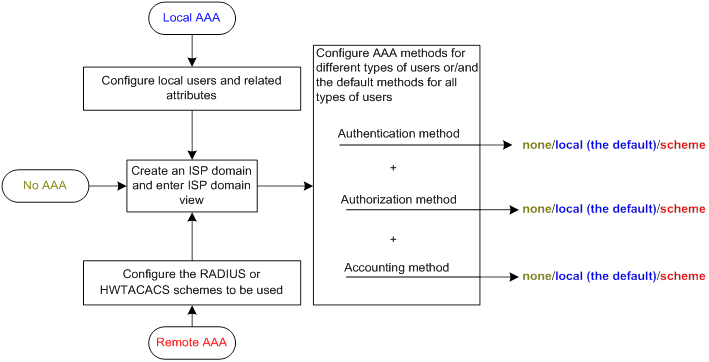
AAA configuration considerations and task list
To configure AAA, complete the following tasks on the NAS:
1. Configure the required AAA schemes:
? Local authentication—Configure local users and the related attributes, including the usernames and passwords, for the users to be authenticated.
? Remote authentication—Configure the required RADIUS and HWTACACS schemes.
2. Configure AAA methods for the users' ISP domains. Remote AAA methods need to use the configured RADIUS and HWTACACS schemes.
Figure 9 AAA configuration procedure
To configure AAA, perform the following tasks:
|
Tasks at a glance |
|
(Required.) Perform a minimum one of the following tasks to configure local users or AAA schemes: |
|
(Required.) Configure AAA methods for ISP domains: 1. (Required.) Creating an ISP domain 2. (Optional.) Configuring ISP domain attributes 3. (Required.) Perform a minimum one of the following tasks to configure AAA authentication, authorization, and accounting methods for the ISP domain: ? Configuring authentication methods for an ISP domain |
|
(Optional.) Configuring the RADIUS session-control feature |
|
(Optional.) Configuring the RADIUS DAS feature |
|
(Optional.) Changing the DSCP priority for RADIUS packets |
|
(Optional.) Configuring the RADIUS attribute translation feature |
|
(Optional.) Setting the maximum number of concurrent login users |
|
(Optional.) Configuring a NAS-ID profile |
|
(Optional.) Configuring the device ID |
Configuring AAA schemes
This section includes information on configuring local users, RADIUS schemes, and HWTACACS schemes.
Configuring local users
To implement local authentication, authorization, and accounting, create local users and configure user attributes on the device. The local users and attributes are stored in the local user database on the device. A local user is uniquely identified by the combination of a username and a user type.
The following shows the configurable local user attributes:
· Service type—Services that the user can use. Local authentication checks the service types of a local user. If none of the service types is available, the user cannot pass authentication.
Service types include FTP, HTTP, HTTPS, SSH, Telnet, and terminal.
· User state—Whether or not a local user can request network services. There are two user states: active and blocked. A user in active state can request network services, but a user in blocked state cannot.
· Upper limit of concurrent logins using the same user name—Maximum number of users that can concurrently access the device by using the same user name. When the number reaches the upper limit, no more local users can access the device by using the user name.
· User group—Each local user belongs to a local user group and has all attributes of the group. The attributes include the password control attributes and authorization attributes. For more information about local user group, see "Configuring user group attributes."
· Authorization attributes—Authorization attributes indicate the user's rights after it passes local authentication. For support information about authorization attributes, see "Configuring local user attributes."
Configure the authorization attributes based on the service type of local users.
You can configure an authorization attribute in user group view or local user view. The setting of an authorization attribute in local user view takes precedence over the attribute setting in user group view.
? The attribute configured in user group view takes effect on all local users in the user group.
? The attribute configured in local user view takes effect only on the local user.
· Password control attributes—Password control attributes help control password security for device management users. Password control attributes include password aging time, minimum password length, password composition checking, password complexity checking, and login attempt limit.
You can configure a password control attribute in system view, user group view, or local user view. A password control attribute with a smaller effective range has a higher priority. For more information about password management and global password configuration, see "Configuring password control."
Local user configuration task list
|
Tasks at a glance |
|
(Required.) Configuring local user attributes |
|
(Optional.) Configuring user group attributes |
Configuring local user attributes
When you configure local user attributes, follow these guidelines:
· When you use the password-control enable command to globally enable the password control feature, local user passwords are not displayed.
· You can configure authorization attributes and password control attributes in local user view or user group view. The setting in local user view takes precedence over the setting in user group view.
To configure local user attributes:
|
Step |
Command |
Remarks |
|
1. Enter system view. |
system-view |
N/A |
|
2. Add a local user and enter local user view. |
local-user user-name [ class manage ] |
By default, no local users exist. |
|
3. (Optional.) Configure a password for the local user. |
·
In non-FIPS mode: ·
In FIPS mode: |
The default settings are as follows: · In non-FIPS mode, no password is configured for a local user. A local user can pass authentication after entering the correct username and passing attribute checks. · In FIPS mode, no password is configured for a local user. A local user cannot pass authentication. |
|
4. Assign services to the local user. |
·
In non-FIPS mode: ·
In FIPS mode: |
By default, no services are authorized to a local user. |
|
5. (Optional.) Place the local user to the active or blocked state. |
state { active | block } |
By default, a local user is in active state and can request network services. |
|
6. (Optional.) Set the upper limit of concurrent logins using the local user name. |
access-limit max-user-number |
By default, the number of concurrent logins is not limited for the local user. This command takes effect only when local accounting is configured for the local user. It does not apply to FTP, SFTP, or SCP users. These users do not support accounting. |
|
7. (Optional.) Configure authorization attributes for the local user. |
authorization-attribute { idle-cut minutes | user-role role-name | work-directory directory-name } * |
The following default settings apply: · The working directory for FTP, SFTP, and SCP users is the root directory of the NAS. However, the users do not have permission to access the root directory. · The network-operator user role is assigned to local users that are created by a network-admin or level-15 user. |
|
8. (Optional.) Configure password control attributes for the local user. |
·
Set the password aging time: ·
Set the minimum password length: ·
Configure the password composition policy: ·
Configure the password complexity
checking policy: ·
Configure the maximum login attempts
and the action to take if there is a login failure: |
By default, the local user uses password control attributes of the user group to which the local user belongs. |
|
9. (Optional.) Assign the local user to a user group. |
group group-name |
By default, a local user belongs to the user group system. |
Configuring user group attributes
User groups simplify local user configuration and management. A user group contains a group of local users and has a set of local user attributes. You can configure local user attributes for a user group to implement centralized user attributes management for the local users in the group. Local user attributes that are manageable include authorization attributes.
By default, every new local user belongs to the default user group system and has all attributes of the group. To assign a local user to a different user group, use the group command in local user view.
To configure user group attributes:
|
Step |
Command |
Remarks |
|
1. Enter system view. |
system-view |
N/A |
|
2. Create a user group and enter user group view. |
user-group group-name |
By default, a system-defined user group exists. The group name is system. |
|
3. Configure authorization attributes for the user group. |
authorization-attribute { idle-cut minutes | work-directory directory-name } * |
By default, no authorization attributes are configured for a user group. |
|
4. (Optional.) Configure password control attributes for the user group. |
·
Set the password aging time: ·
Set the minimum password length: ·
Configure the password composition policy: ·
Configure the password complexity
checking policy: ·
Configure the maximum login attempts
and the action to take for login failures: |
By default, the user group uses the global password control settings. For more information, see "Configuring password control." |
Displaying and maintaining local users and local user groups
Execute display commands in any view.
|
Task |
Command |
|
Display the local user configuration and online user statistics. |
display local-user [ class manage | idle-cut { disable | enable } | service-type { ftp | http | https | ssh | telnet | terminal } | state { active | block } | user-name user-name class manage | vlan vlan-id ] |
|
Display the user group configuration. |
display user-group { all | name group-name } |
Configuring RADIUS schemes
A RADIUS scheme specifies the RADIUS servers that the device can work with and defines a set of parameters. The device uses the parameters to exchange information with the RADIUS servers, including the server IP addresses, UDP port numbers, shared keys, and server types.
Configuration task list
Configuring a test profile for RADIUS server status detection
Use a test profile to detect whether a RADIUS authentication server is reachable at a detection interval. To detect the RADIUS server status, you must configure the RADIUS server to use this test profile in a RADIUS scheme.
With the test profile specified, the device sends a detection packet to the RADIUS server within each detection interval. The detection packet is a simulated authentication request that includes the specified user name in the test profile.
· If the device receives a response from the server within the interval, it sets the server to the active state.
· If the device does not receive any response from the server within the interval, it sets the server to the blocked state.
The device refreshes the RADIUS server status at each detection interval according to the detection result.
The device stops detecting the status of the RADIUS server when one of the following operations is performed:
· The RADIUS server is removed from the RADIUS scheme.
· The test profile configuration is removed for the RADIUS server in RADIUS scheme view.
· The test profile is deleted.
· The RADIUS server is manually set to the blocked state.
· The RADIUS scheme is deleted.
To configure a test profile for RADIUS server status detection:
|
Step |
Command |
Remarks |
|
1. Enter system view. |
system-view |
N/A |
|
2. Configure a test profile for detecting the status of RADIUS authentication servers. |
radius-server test-profile profile-name username name [ interval interval ] |
By default, no test profiles exist. You can configure multiple test profiles in the system. |
Creating a RADIUS scheme
Create a RADIUS scheme before performing any other RADIUS configurations. You can configure a maximum of 16 RADIUS schemes. A RADIUS scheme can be used by multiple ISP domains.
To create a RADIUS scheme:
|
Step |
Command |
Remarks |
|
1. Enter system view. |
system-view |
N/A |
|
2. Create a RADIUS scheme and enter RADIUS scheme view. |
radius scheme radius-scheme-name |
By default, no RADIUS schemes exist. |
Specifying the RADIUS authentication servers
A RADIUS authentication server completes authentication and authorization together, because authorization information is piggybacked in authentication responses sent to RADIUS clients.
You can specify one primary authentication server and a maximum of 16 secondary authentication servers for a RADIUS scheme. Secondary servers provide AAA services when the primary server becomes unavailable. The device searches for an active server in the order the secondary servers are configured.
If redundancy is not required, specify only the primary server. A RADIUS authentication server can function as the primary authentication server for one scheme and a secondary authentication server for another scheme at the same time.
When RADIUS server load sharing is enabled, the device distributes the workload over all servers without considering the primary and secondary server roles. The device checks the weight value and number of currently served users for each active server, and then determines the most appropriate server in performance to receive an authentication request.
To specify RADIUS authentication servers for a RADIUS scheme:
|
Step |
Command |
Remarks |
|
1. Enter system view. |
system-view |
N/A |
|
2. Enter RADIUS scheme view. |
radius scheme radius-scheme-name |
N/A |
|
3. Specify RADIUS authentication servers. |
·
Specify the primary RADIUS authentication
server: ·
Specify a secondary RADIUS authentication
server: |
By default, no authentication servers are specified. To support server status detection, specify an existing test profile for the RADIUS authentication server. If the test profile does not exist, the device cannot detect the server status. Two authentication servers in a scheme, primary or secondary, cannot have the same combination of IP address, port number, and VPN instance. The weight keyword takes effect only when the RADIUS server load sharing feature is enabled for the RADIUS scheme. |
Specifying the RADIUS accounting servers and the relevant parameters
You can specify one primary accounting server and a maximum of 16 secondary accounting servers for a RADIUS scheme. Secondary servers provide AAA services when the primary server becomes unavailable. The device searches for an active server in the order the secondary servers are configured.
If redundancy is not required, specify only the primary server. A RADIUS accounting server can function as the primary accounting server for one scheme and a secondary accounting server for another scheme at the same time.
When RADIUS server load sharing is enabled, the device distributes the workload over all servers without considering the primary and secondary server roles. The device checks the weight value and number of currently served users for each active server, and then determines the most appropriate server in performance to receive an accounting request.
The device sends a stop-accounting request to the accounting server in the following situations:
· The device receives a connection teardown request from a host.
· The device receives a connection teardown command from an administrator.
When the maximum number of real-time accounting attempts is reached, the device disconnects users that have no accounting responses.
RADIUS does not support accounting for FTP, SFTP, and SCP users.
To specify RADIUS accounting servers and the relevant parameters for a RADIUS scheme:
|
Step |
Command |
Remarks |
|
1. Enter system view. |
system-view |
N/A |
|
2. Enter RADIUS scheme view. |
radius scheme radius-scheme-name |
N/A |
|
3. Specify RADIUS accounting servers. |
·
Specify the primary RADIUS accounting server: ·
Specify a secondary RADIUS accounting server: |
By default, no accounting servers are specified. Two accounting servers in a scheme, primary or secondary, cannot have the same combination of IP address, port number, and VPN instance. The weight keyword takes effect only when the RADIUS server load sharing feature is enabled for the RADIUS scheme. |
|
4. (Optional.) Set the maximum number of real-time accounting attempts. |
retry realtime-accounting retries |
The default setting is 5. |
Specifying the shared keys for secure RADIUS communication
The RADIUS client and server use the MD5 algorithm and shared keys to generate the Authenticator value for packet authentication and user password encryption. The client and server must use the same key for each type of communication.
A key configured in this task is for all servers of the same type (accounting or authentication) in the scheme. The key has a lower priority than a key configured individually for a RADIUS server.
To specify a shared key for secure RADIUS communication:
|
Step |
Command |
Remarks |
|
1. Enter system view. |
system-view |
N/A |
|
2. Enter RADIUS scheme view. |
radius scheme radius-scheme-name |
N/A |
|
3. Specify a shared key for secure RADIUS communication. |
key { accounting | authentication } { cipher | simple } string |
By default, no shared key is specified for secure RADIUS communication. The shared key configured on the device must be the same as the shared key configured on the RADIUS server. |
Specifying an MPLS L3VPN instance for the scheme
The VPN instance specified for a RADIUS scheme applies to all authentication and accounting servers in that scheme. If a VPN instance is also configured for an individual RADIUS server, the VPN instance specified for the RADIUS scheme does not take effect on that server.
To specify a VPN instance for a scheme:
|
Step |
Command |
Remarks |
|
1. Enter system view. |
system-view |
N/A |
|
2. Enter RADIUS scheme view. |
radius scheme radius-scheme-name |
N/A |
|
3. Specify a VPN instance for the RADIUS scheme. |
vpn-instance vpn-instance-name |
By default, a RADIUS scheme belongs to the public network. |
Setting the username format and traffic statistics units
A username is in the userid@isp-name format, where the isp-name argument represents the user's ISP domain name. By default, the ISP domain name is included in a username. However, older RADIUS servers might not recognize usernames that contain the ISP domain names. In this case, you can configure the device to remove the domain name of each username to be sent.
If two or more ISP domains use the same RADIUS scheme, configure the RADIUS scheme to keep the ISP domain name in usernames for domain identification.
The device reports online user traffic statistics in accounting packets. The traffic measurement units are configurable, but they must be the same as the traffic measurement units configured on the RADIUS accounting servers.
To set the username format and the traffic statistics units for a RADIUS scheme:
|
Step |
Command |
Remarks |
|
1. Enter system view. |
system-view |
N/A |
|
2. Enter RADIUS scheme view. |
radius scheme radius-scheme-name |
N/A |
|
3. Set the format for usernames sent to the RADIUS servers. |
user-name-format { keep-original | with-domain | without-domain } |
By default, the ISP domain name is included in a username. |
|
4. (Optional.) Set the data flow and packet measurement units for traffic statistics. |
data-flow-format { data { byte | giga-byte | kilo-byte | mega-byte } | packet { giga-packet | kilo-packet | mega-packet | one-packet } } * |
By default, traffic is counted in bytes and packets. |
Setting the maximum number of RADIUS request transmission attempts
RADIUS uses UDP packets to transfer data. Because UDP communication is not reliable, RADIUS uses a retransmission mechanism to improve reliability. A RADIUS request is retransmitted if the NAS does not receive a server response for the request within the response timeout timer. For more information about the RADIUS server response timeout timer, see "Setting RADIUS timers."
You can set the maximum number for the NAS to retransmit a RADIUS request to the same server. When the maximum number is reached, the NAS tries to communicate with other RADIUS servers in active state. If no other servers are in active state at the time, the NAS considers the authentication or accounting attempt a failure.
To set the maximum number of RADIUS request transmission attempts:
|
Step |
Command |
Remarks |
|
1. Enter system view. |
system-view |
N/A |
|
2. Enter RADIUS scheme view. |
radius scheme radius-scheme-name |
N/A |
|
3. Set the maximum number of RADIUS request transmission attempts. |
retry retries |
The default setting is 3. |
Setting the status of RADIUS servers
To control the RADIUS servers with which the device communicates when the current servers are no longer available, set the status of RADIUS servers to blocked or active. You can specify one primary RADIUS server and multiple secondary RADIUS servers. The secondary servers function as the backup of the primary server. When the RADIUS server load sharing feature is disabled, the device chooses servers based on the following rules:
· When the primary server is in active state, the device communicates with the primary server.
· If the primary server fails, the device performs the following operations:
? Changes the server status to blocked.
? Starts a quiet timer for the server.
? Tries to communicate with a secondary server in active state that has the highest priority.
· If the secondary server is unreachable, the device performs the following operations:
? Changes the server status to blocked.
? Starts a quiet timer for the server.
? Tries to communicate with the next secondary server in active state that has the highest priority.
· The search process continues until the device finds an available secondary server or has checked all secondary servers in active state. If no server is available, the device considers the authentication or accounting attempt a failure.
· When the quiet timer of a server expires or you manually set the server to the active state, the status of the server changes back to active. The device does not check the server again during the authentication or accounting process.
· When you remove a server in use, communication with the server times out. The device looks for a server in active state by first checking the primary server, and then checking secondary servers in the order they are configured.
· When all servers are in blocked state, the device only tries to communicate with the primary server.
· When one or more servers are in active state, the device tries to communicate with these active servers only, even if the servers are unavailable.
· When a RADIUS server's status changes automatically, the device changes this server's status accordingly in all RADIUS schemes in which this server is specified.
· When a RADIUS server is manually set to blocked, server detection is disabled for the server, regardless of whether a test profile has been specified for the server. When the RADIUS server is set to active state, server detection is enabled for the server on which an existing test profile is specified.
By default, the device sets the status of all RADIUS servers to active. However, in some situations, you must change the status of a server. For example, if a server fails, you can change the status of the server to blocked to avoid communication attempts to the server.
When RADIUS server load sharing is enabled, the device distributes the workload over all servers without considering the primary and secondary server roles. The device checks the weight value and number of currently served users for each active server, and then determines the most appropriate server in performance to receive an AAA request.
In RADIUS server load sharing, once the device sends a start-accounting request to a server for a user, it forwards all subsequent accounting requests of the user to the same server. If the accounting server is unreachable, the device returns an accounting failure message rather than searching for another active accounting server.
To set the status of RADIUS servers:
|
Step |
Command |
Remarks |
|
1. Enter system view. |
system-view |
N/A |
|
2. Enter RADIUS scheme view. |
radius scheme radius-scheme-name |
N/A |
|
3. Set the RADIUS server status. |
·
Set the status of the primary RADIUS
authentication server: ·
Set the status of the primary RADIUS
accounting server: ·
Set the status of a secondary RADIUS
authentication server: ·
Set the status of a secondary RADIUS
accounting server: |
By default, a RADIUS server is in active state. The configured server status cannot be saved to any configuration file, and can only be viewed by using the display radius scheme command. After the device restarts, all servers are restored to the active state. |
Enabling the RADIUS server load sharing feature
By default, the device communicates with RADIUS servers based on the server roles. It first attempts to communicate with the primary server, and, if the primary server is unavailable, it then searches for the secondary servers in the order they are configured. The first secondary server in active state is used for communication. In this process, the workload is always placed on the active server.
Use the RADIUS server load sharing feature to dynamically distribute the workload over multiple servers regardless of their server roles. The device forwards an AAA request to the most appropriate server of all active servers in the scheme after it compares the weight values and numbers of currently served users. Specify a weight value for each RADIUS server based on the AAA capacity of the server. A larger weight value indicates a higher AAA capacity.
In RADIUS server load sharing, once the device sends a start-accounting request to a server for a user, it forwards all subsequent accounting requests of the user to the same server. If the accounting server is unreachable, the device returns an accounting failure message rather than searching for another active accounting server.
To enable the RADIUS server load sharing feature:
|
Step |
Command |
Remarks |
|
1. Enter system view. |
system-view |
N/A |
|
2. Enter RADIUS scheme view. |
radius scheme radius-scheme-name |
N/A |
|
3. Enable the RADIUS server load sharing feature. |
server-load-sharing enable |
By default, this feature is disabled. |
Specifying the source IP address for outgoing RADIUS packets
The source IP address of RADIUS packets that a NAS sends must match the IP address of the NAS configured on the RADIUS server. A RADIUS server identifies a NAS by its IP address. Upon receiving a RADIUS packet, a RADIUS server checks whether the source IP address of the packet is the IP address of a managed NAS.
· If it is the IP address of a managed NAS, the server processes the packet.
· If it is not the IP address of a managed NAS, the server drops the packet.
The source address of outgoing RADIUS packets is typically the IP address of an egress interface on the NAS to communicate with the RADIUS server. However, in some situations, you must change the source IP address. For example, when VRRP is configured for stateful failover, configure the virtual IP of the uplink VRRP group as the source address.
You can specify a source IP address for outgoing RADIUS packets in RADIUS scheme view or in system view.
· The IP address specified in RADIUS scheme view applies only to one RADIUS scheme.
· The IP address specified in system view applies to all RADIUS schemes in which the RADIUS servers are in a VPN or the public network.
Before sending a RADIUS packet, the NAS selects a source IP address in the following order:
1. The source IP address specified for the RADIUS scheme.
2. The source IP address specified in system view for the VPN or public network, depending on where the RADIUS server resides.
3. The IP address of the outbound interface specified by the route.
To specify a source IP address for all RADIUS schemes in a VPN or the public network:
|
Step |
Command |
Remarks |
|
1. Enter system view. |
system-view |
N/A |
|
2. Specify a source IP address for outgoing RADIUS packets. |
radius nas-ip { ipv4-address | ipv6 ipv6-address } [ vpn-instance vpn-instance-name ] |
By default, the primary IP address of the RADIUS packet outbound interface is used as the source IP address. |
To specify a source IP address for a RADIUS scheme:
|
Step |
Command |
Remarks |
|
1. Enter system view. |
system-view |
N/A |
|
2. Enter RADIUS scheme view. |
radius scheme radius-scheme-name |
N/A |
|
3. Specify a source IP address for outgoing RADIUS packets. |
nas-ip { ipv4-address | ipv6 ipv6-address } |
By default, the source IP address specified by the radius nas-ip command in system view is used. If the source IP address is not specified, the primary IP address of the outbound interface is used. |
Setting RADIUS timers
The device uses the following types of timers to control communication with a RADIUS server:
· Server response timeout timer (response-timeout)—Defines the RADIUS request retransmission interval. The timer starts immediately after a RADIUS request is sent. If the device does not receive a response from the RADIUS server before the timer expires, it resends the request.
· Server quiet timer (quiet)—Defines the duration to keep an unreachable server in blocked state. If one server is not reachable, the device changes the server status to blocked, starts this timer for the server, and tries to communicate with another server in active state. After the server quiet timer expires, the device changes the status of the server back to active.
· Real-time accounting timer (realtime-accounting)—Defines the interval at which the device sends real-time accounting packets to the RADIUS accounting server for online users.
When you set RADIUS timers, follow these guidelines:
· Consider the number of secondary servers when you configure the maximum number of RADIUS packet transmission attempts and the RADIUS server response timeout timer. If the RADIUS scheme includes many secondary servers, the retransmission process might be too long and the client connection in the access module, such as Telnet, can time out.
· When the client connections have a short timeout period, a large number of secondary servers can cause the initial authentication or accounting attempt to fail. In this case, reconnect the client rather than adjusting the RADIUS packet transmission attempts and server response timeout timer. Typically, the next attempt will succeed, because the device has blocked the unreachable servers to shorten the time to find a reachable server.
· Make sure the server quiet timer is set correctly. A timer that is too short might result in frequent authentication or accounting failures. This is because the device will continue to attempt to communicate with an unreachable server that is in active state. A timer that is too long might temporarily block a reachable server that has recovered from a failure. This is because the server will remain in blocked state until the timer expires.
· A short real-time accounting interval helps improve accounting precision but requires many system resources. When there are 1000 or more users, set the interval to 15 minutes or longer.
To set RADIUS timers:
|
Step |
Command |
Remarks |
|
1. Enter system view. |
system-view |
N/A |
|
2. Enter RADIUS scheme view. |
radius scheme radius-scheme-name |
N/A |
|
3. Set the RADIUS server response timeout timer. |
timer response-timeout seconds |
The default setting is 3 seconds. |
|
4. Set the quiet timer for the servers. |
timer quiet minutes |
The default setting is 5 minutes. |
|
5. Set the real-time accounting timer. |
timer realtime-accounting interval [ second ] |
The default setting is 12 minutes. |
Configuring the RADIUS accounting-on feature
When the accounting-on feature is enabled, the device automatically sends an accounting-on packet to the RADIUS server after the entire device reboots. Upon receiving the accounting-on packet, the RADIUS server logs out all online users so they can log in again through the device. Without this feature, users cannot log in again after the reboot, because the RADIUS server considers them to come online.
You can configure the interval for which the device waits to resend the accounting-on packet and the maximum number of retries.
The extended accounting-on feature enhances the accounting-on feature in a distributed architecture. For the extended accounting-on feature to take effect, the RADIUS server must run on IMC and the accounting-on feature must be enabled.
To configure the accounting-on feature for a RADIUS scheme:
|
Step |
Command |
Remarks |
|
1. Enter system view. |
system-view |
N/A |
|
2. Enter RADIUS scheme view. |
radius scheme radius-scheme-name |
N/A |
|
3. Enable accounting-on. |
accounting-on enable [ interval interval | send send-times ] * |
By default, the accounting-on feature is disabled. |
|
4. (Optional.) Enable extended accounting-on. |
accounting-on extended |
By default, extended accounting-on is disabled. |
Interpreting the RADIUS class attribute as CAR parameters
A RADIUS server may deliver CAR parameters for user-based traffic monitoring and control by using the RADIUS class attribute (attribute 25) in RADIUS packets. You can configure the device to interpret the class attribute to CAR parameters.
To configure the device to interpret the RADIUS class attribute as CAR parameters:
|
Step |
Command |
Remarks |
|
1. Enter system view. |
system-view |
N/A |
|
2. Enter RADIUS scheme view. |
radius scheme radius-scheme-name |
N/A |
|
3. Interpret the RADIUS class attribute as CAR parameters. |
attribute 25 car |
By default, the RADIUS class attribute is not interpreted as CAR parameters. |
Configuring the Login-Service attribute check method for SSH, FTP, and terminal users
· Strict—Matches Login-Service attribute values 50, 51, and 52 for SSH, FTP, and terminal services, respectively.
· Loose—Matches the standard Login-Service attribute value 0 for SSH, FTP, and terminal services.
An Access-Accept packet received for a user must contain the matching attribute value. Otherwise, the user cannot log in to the device.
Use the loose check method only when the server does not issue Login-Service attribute values 50, 51, and 52 for SSH, FTP, and terminal users.
To configure the Login-Service attribute check method for SSH, FTP, and terminal users:
|
Step |
Command |
Remarks |
|
1. Enter system view. |
system-view |
N/A |
|
2. Enter RADIUS scheme view. |
radius scheme radius-scheme-name |
N/A |
|
3. Configure the Login-Service attribute check method for SSH, FTP, and terminal users. |
attribute 15 check-mode { loose | strict } |
The default check method is strict. |
Configuring the MAC address format for RADIUS attribute 31
RADIUS servers of different types might have different requirements for the MAC address format in RADIUS attribute 31. Configure the MAC address format for RADIUS attribute 31 to meet the requirements of the RADIUS servers.
To configure the MAC address format for RADIUS attribute 31:
|
Step |
Command |
Remarks |
|
1. Enter system view. |
system-view |
N/A |
|
2. Enter RADIUS scheme view. |
radius scheme radius-scheme-name |
N/A |
|
3. Configure the MAC address format for RADIUS attribute 31. |
attribute 31 mac-format section { six | three } separator separator-character { lowercase | uppercase } |
By default, a MAC address is in the format of HH-HH-HH-HH-HH-HH. The MAC address is separated by hyphen (-) into six sections with letters in upper case. |
Setting the data measurement unit for the Remanent_Volume attribute
The Remanent_Volume attribute is H3C proprietary. The RADIUS server uses this attribute in authentication or real-time accounting responses to notify the device of the current amount of data available for online users.
Perform this task to set the data measurement unit for the Remanent_Volume attribute. Make sure the configured measurement unit is the same as the user data measurement unit on the RADIUS server.
To set the data measurement unit for the Remanent_Volume attribute:
|
Step |
Command |
Remarks |
|
1. Enter system view. |
system-view |
N/A |
|
2. Enter RADIUS scheme view. |
radius scheme radius-scheme-name |
N/A |
|
3. Set the data measurement unit for the Remanent_Volume attribute. |
attribute remanent-volume unit { byte | giga-byte | kilo-byte | mega-byte } |
By default, the data measurement unit is kilobyte. |
Enabling SNMP notifications for RADIUS
When SNMP notifications are enabled for RADIUS, the SNMP agent supports the following notifications generated by RADIUS:
· RADIUS server unreachable notification—The RADIUS server cannot be reached. RADIUS generates this notification if it does not receive a response to an accounting or authentication request within the specified number of RADIUS request transmission attempts.
· RADIUS server reachable notification—The RADIUS server can be reached. RADIUS generates this notification for a previously blocked RADIUS server after the quiet timer expires.
· Excessive authentication failures notification—The number of authentication failures compared to the total number of authentication attempts exceeds the specified threshold.
For RADIUS SNMP notifications to be sent correctly, you must also configure SNMP on the device. For more information about SNMP configuration, see the network management and monitoring configuration guide for the device.
To enable SNMP notifications for RADIUS:
|
Step |
Command |
Remarks |
|
1. Enter system view. |
system-view |
N/A |
|
2. Enable SNMP notifications for RADIUS. |
snmp-agent trap enable radius [ accounting-server-down | accounting-server-up | authentication-error-threshold | authentication-server-down | authentication-server-up ] * |
By default, all SNMP notifications are disabled for RADIUS. |
Displaying and maintaining RADIUS
Execute display commands in any view and reset commands in user view.
|
Task |
Command |
|
Display the RADIUS scheme configuration. |
display radius scheme [ radius-scheme-name ] |
|
Display RADIUS packet statistics. |
display radius statistics |
|
Clear RADIUS statistics. |
reset radius statistics |
Configuring HWTACACS schemes
Configuration task list
|
Tasks at a glance |
|
(Required.) Creating an HWTACACS scheme |
|
(Required.) Specifying the HWTACACS authentication servers |
|
(Optional.) Specifying the HWTACACS authorization servers |
|
(Optional.) Specifying the HWTACACS accounting servers |
|
(Required.) Specifying the shared keys for secure HWTACACS communication |
|
(Optional.) Specifying an MPLS L3VPN instance for the scheme |
|
(Optional.) Setting the username format and traffic statistics units |
|
(Optional.) Specifying the source IP address for outgoing HWTACACS packets |
|
(Optional.) Setting HWTACACS timers |
Creating an HWTACACS scheme
Create an HWTACACS scheme before performing any other HWTACACS configurations. You can configure a maximum of 16 HWTACACS schemes. An HWTACACS scheme can be used by multiple ISP domains.
To create an HWTACACS scheme:
|
Step |
Command |
Remarks |
|
1. Enter system view. |
system-view |
N/A |
|
2. Create an HWTACACS scheme and enter HWTACACS scheme view. |
hwtacacs scheme hwtacacs-scheme-name |
By default, no HWTACACS schemes exist. |
Specifying the HWTACACS authentication servers
You can specify one primary authentication server and a maximum of 16 secondary authentication servers for an HWTACACS scheme. When the primary server is not available, the device searches for the secondary servers in the order they are configured. The first secondary server in active state is used for communication.
If redundancy is not required, specify only the primary server. An HWTACACS server can function as the primary authentication server in one scheme and as the secondary authentication server in another scheme at the same time.
To specify HWTACACS authentication servers for an HWTACACS scheme:
|
Step |
Command |
Remarks |
|
1. Enter system view. |
system-view |
N/A |
|
2. Enter HWTACACS scheme view. |
hwtacacs scheme hwtacacs-scheme-name |
N/A |
|
3. Specify HWTACACS authentication servers. |
·
Specify the primary HWTACACS authentication
server: ·
Specify a secondary HWTACACS authentication
server: |
By default, no authentication servers are specified. Two HWTACACS authentication servers in a scheme, primary or secondary, cannot have the same combination of IP address, port number, and VPN instance. |
Specifying the HWTACACS authorization servers
You can specify one primary authorization server and a maximum of 16 secondary authorization servers for an HWTACACS scheme. When the primary server is not available, the device searches for the secondary servers in the order they are configured. The first secondary server in active state is used for communication.
If redundancy is not required, specify only the primary server. An HWTACACS server can function as the primary authorization server of one scheme and as the secondary authorization server of another scheme at the same time.
To specify HWTACACS authorization servers for an HWTACACS scheme:
|
Step |
Command |
Remarks |
|
1. Enter system view. |
system-view |
N/A |
|
2. Enter HWTACACS scheme view. |
hwtacacs scheme hwtacacs-scheme-name |
N/A |
|
3. Specify HWTACACS authorization servers. |
·
Specify the primary HWTACACS authorization
server: ·
Specify a secondary HWTACACS authorization
server: |
By default, no authorization servers are specified. Two HWTACACS authorization servers in a scheme, primary or secondary, cannot have the same combination of IP address, port number, and VPN instance. |
Specifying the HWTACACS accounting servers
You can specify one primary accounting server and a maximum of 16 secondary accounting servers for an HWTACACS scheme. When the primary server is not available, the device searches for the secondary servers in the order they are configured. The first secondary server in active state is used for communication.
If redundancy is not required, specify only the primary server. An HWTACACS server can function as the primary accounting server of one scheme and as the secondary accounting server of another scheme at the same time.
HWTACACS does not support accounting for FTP, SFTP, and SCP users.
To specify HWTACACS accounting servers for an HWTACACS scheme:
|
Step |
Command |
Remarks |
|
1. Enter system view. |
system-view |
N/A |
|
2. Enter HWTACACS scheme view. |
hwtacacs scheme hwtacacs-scheme-name |
N/A |
|
3. Specify HWTACACS accounting servers. |
·
Specify the primary HWTACACS accounting
server: ·
Specify a secondary HWTACACS accounting
server: |
By default, no accounting servers are specified. Two HWTACACS accounting servers in a scheme, primary or secondary, cannot have the same combination of IP address, port number, and VPN instance. |
Specifying the shared keys for secure HWTACACS communication
The HWTACACS client and server use the MD5 algorithm and shared keys to generate the Authenticator value for packet authentication and user password encryption. The client and server must use the same key for each type of communication.
Perform this task to configure shared keys for servers in an HWTACACS scheme. The keys take effect on all servers for which a shared key is not individually configured.
To specify a shared key for secure HWTACACS communication:
|
Step |
Command |
Remarks |
|
1. Enter system view. |
system-view |
N/A |
|
2. Enter HWTACACS scheme view. |
hwtacacs scheme hwtacacs-scheme-name |
N/A |
|
3. Specify a shared key for secure HWTACACS authentication, authorization, or accounting communication. |
key { accounting | authentication | authorization } { cipher | simple } string |
By default, no shared key is specified for secure HWTACACS communication. The shared key configured on the device must be the same as the shared key configured on the HWTACACS server. |
Specifying an MPLS L3VPN instance for the scheme
The VPN instance specified for an HWTACACS scheme applies to all servers in that scheme. If a VPN instance is also configured for an individual HWTACACS server, the VPN instance specified for the HWTACACS scheme does not take effect on that server.
To specify a VPN instance for an HWTACACS scheme:
|
Step |
Command |
Remarks |
|
1. Enter system view. |
system-view |
N/A |
|
2. Enter HWTACACS scheme view. |
hwtacacs scheme hwtacacs-scheme-name |
N/A |
|
3. Specify a VPN instance for the HWTACACS scheme. |
vpn-instance vpn-instance-name |
By default, an HWTACACS scheme belongs to the public network. |
Setting the username format and traffic statistics units
A username is typically in the userid@isp-name format, where the isp-name argument represents the user's ISP domain name. By default, the ISP domain name is included in a username. If HWTACACS servers do not recognize usernames that contain ISP domain names, you can configure the device to send usernames without domain names to the servers.
If two or more ISP domains use the same HWTACACS scheme, configure the HWTACACS scheme to keep the ISP domain name in usernames for domain identification.
The device reports online user traffic statistics in accounting packets. The traffic measurement units are configurable, but they must be the same as the traffic measurement units configured on the HWTACACS accounting servers.
To set the username format and traffic statistics units for an HWTACACS scheme:
|
Step |
Command |
Remarks |
|
1. Enter system view. |
system-view |
N/A |
|
2. Enter HWTACACS scheme view. |
hwtacacs scheme hwtacacs-scheme-name |
N/A |
|
3. Set the format of usernames sent to the HWTACACS servers. |
user-name-format { keep-original | with-domain | without-domain } |
By default, the ISP domain name is included in a username. |
|
4. (Optional.) Set the data flow and packet measurement units for traffic statistics. |
data-flow-format { data { byte | giga-byte | kilo-byte | mega-byte } | packet { giga-packet | kilo-packet | mega-packet | one-packet } } * |
By default, traffic is counted in bytes and packets. |
Specifying the source IP address for outgoing HWTACACS packets
The source IP address of HWTACACS packets that a NAS sends must match the IP address of the NAS configured on the HWTACACS server. An HWTACACS server identifies a NAS by IP address. When the HWTACACS server receives a packet, it checks whether the source IP address of the packet is the IP address of a managed NAS.
· If it is the IP address of a managed NAS, the server processes the packet.
· If it is not the IP address of a managed NAS, the server drops the packet.
To communicate with the HWTACACS server, the source address of outgoing HWTACACS packets is typically the IP address of an egress interface on the NAS. However, in some situations, you must change the source IP address. For example, when VRRP is configured for stateful failover, configure the virtual IP of the uplink VRRP group as the source address.
You can specify the source IP address for outgoing HWTACACS packets in HWTACACS scheme view or in system view.
· The IP address specified in HWTACACS scheme view applies to one HWTACACS scheme.
· The IP address specified in system view applies to all HWTACACS schemes in which the HWTACACS servers are in a VPN or the public network.
Before sending an HWTACACS packet, the NAS selects a source IP address in the following order:
1. The source IP address specified for the HWTACACS scheme.
2. The source IP address specified in system view for the VPN or public network, depending on where the HWTACACS server resides.
3. The IP address of the outbound interface specified by the route.
To specify a source IP address for all HWTACACS schemes of a VPN or the public network:
|
Step |
Command |
Remarks |
|
1. Enter system view. |
system-view |
N/A |
|
2. Specify a source IP address for outgoing HWTACACS packets. |
hwtacacs nas-ip { ipv4-address | ipv6 ipv6-address } [ vpn-instance vpn-instance-name ] |
By default, the primary IP address of the HWTACACS packet outbound interface is used as the source IP address. |
To specify a source IP address for an HWTACACS scheme:
|
Step |
Command |
Remarks |
|
1. Enter system view. |
system-view |
N/A |
|
2. Enter HWTACACS scheme view. |
hwtacacs scheme hwtacacs-scheme-name |
N/A |
|
3. Specify the source IP address of outgoing HWTACACS packets. |
nas-ip { ipv4-address | ipv6 ipv6-address } |
By default, the source IP address specified by the hwtacacs nas-ip command in system view is used. If the source IP address is not specified, the primary IP address of the outbound interface is used. |
Setting HWTACACS timers
The device uses the following timers to control communication with an HWTACACS server:
· Server response timeout timer (response-timeout)—Defines the HWTACACS server response timeout timer. The device starts this timer immediately after an HWTACACS authentication, authorization, or accounting request is sent. If the device does not receive a response from the server within the timer, it sets the server to blocked. Then, the device sends the request to another HWTACACS server.
· Real-time accounting timer (realtime-accounting)—Defines the interval at which the device sends real-time accounting packets to the HWTACACS accounting server for online users.
· Server quiet timer (quiet)—Defines the duration to keep an unreachable server in blocked state. If a server is not reachable, the device changes the server status to blocked, starts this timer for the server, and tries to communicate with another server in active state. After the server quiet timer expires, the device changes the status of the server back to active.
The server quiet timer setting affects the status of HWTACACS servers. If the scheme includes one primary HWTACACS server and multiple secondary HWTACACS servers, the device communicates with the HWTACACS servers based on the following rules:
· When the primary server is in active state, the device communicates with the primary server.
· If the primary server fails, the device performs the following operations:
? Changes the server status to blocked.
? Starts a quiet timer for the server.
? Tries to communicate with a secondary server in active state that has the highest priority.
· If the secondary server is unreachable, the device performs the following operations:
? Changes the server status to blocked.
? Starts a quiet timer for the server.
? Tries to communicate with the next secondary server in active state that has the highest priority.
· The search process continues until the device finds an available secondary server or has checked all secondary servers in active state. If no server is available, the device considers the authentication, authorization, or accounting attempt a failure.
· When the quiet timer of a server expires, the status of the server changes back to active. The device does not check the server again during the authentication, authorization, or accounting process.
· When you remove a server in use, communication with the server times out. The device looks for a server in active state by first checking the primary server, and then checking secondary servers in the order they are configured.
· When all servers are in blocked state, the device only tries to communicate with the primary server.
· When one or more servers are in active state, the device tries to communicate with these servers only, even if they are unavailable.
· When an HWTACACS server's status changes automatically, the device changes this server's status accordingly in all HWTACACS schemes in which this server is specified.
To set HWTACACS timers:
|
Step |
Command |
Remarks |
|
1. Enter system view. |
system-view |
N/A |
|
2. Enter HWTACACS scheme view. |
hwtacacs scheme hwtacacs-scheme-name |
N/A |
|
3. Set the HWTACACS server response timeout timer. |
timer response-timeout seconds |
By default, the HWTACACS server response timeout timer is 5 seconds. |
|
4. Set the real-time accounting interval. |
timer realtime-accounting minutes |
By default, the real-time accounting interval is 12 minutes. A short interval helps improve accounting precision but requires many system resources. When there are 1000 or more users, set a longer interval. |
|
5. Set the server quiet timer. |
timer quiet minutes |
By default, the server quiet timer is 5 minutes. |
Displaying and maintaining HWTACACS
Execute display commands in any view and reset commands in user view.
|
Task |
Command |
|
Display the configuration or server statistics of HWTACACS schemes. |
display hwtacacs scheme [ hwtacacs-scheme-name [ statistics ] ] |
|
Clear HWTACACS statistics. |
reset hwtacacs statistics { accounting | all | authentication | authorization } |
Configuring AAA methods for ISP domains
You configure AAA methods for an ISP domain by specifying configured AAA schemes in ISP domain view. Each ISP domain has a set of system-defined AAA methods, which are local authentication, local authorization, and local accounting. If you do not configure any AAA methods for an ISP domain, the device uses the system-defined AAA methods for users in the domain.
AAA is available to login users after you enable scheme authentication for the users. For more information about the login authentication modes, see Fundamentals Configuration Guide.
Configuration prerequisites
To use local authentication for users in an ISP domain, configure local user accounts on the device first. See "Configuring local user attributes."
To use remote authentication, authorization, and accounting, create the required RADIUS or HWTACACS schemes. For more information about the scheme configuration, see "Configuring RADIUS schemes" and "Configuring HWTACACS schemes."
Creating an ISP domain
In a networking scenario with multiple ISPs, the device can connect to users of different ISPs. These users can have different user attributes, such as different username and password structures, different service types, and different rights. To manage users of different ISPs, configure AAA methods and domain attributes for each ISP domain as needed.
The device supports a maximum of 16 ISP domains, including the system-defined ISP domain system. You can specify one of the ISP domains as the default domain.
On the device, each user belongs to an ISP domain. If a user does not provide an ISP domain name at login, the device considers the user belongs to the default ISP domain.
The device chooses an authentication domain for each user in the following order:
1. The authentication domain specified for the access module.
2. The ISP domain in the username.
3. The default ISP domain of the device.
If the chosen domain does not exist on the device, the device searches for the ISP domain that accommodates users assigned to nonexistent domains. If no such ISP domain is configured, user authentication fails.
When you configure an ISP domain, follow these restrictions and guidelines:
· An ISP domain cannot be deleted when it is the default ISP domain. Before you use the undo domain command, change the domain to a non-default ISP domain by using the undo domain default enable command.
· You can modify the settings of the system-defined ISP domain system, but you cannot delete the domain.
To create an ISP domain:
|
Step |
Command |
Remarks |
|
1. Enter system view. |
system-view |
N/A |
|
2. Create an ISP domain and enter ISP domain view. |
domain isp-name |
By default, a system-defined ISP domain exists. The domain name is system. |
|
3. Return to system view. |
quit |
N/A |
|
4. (Optional.) Specify the default ISP domain. |
domain default enable isp-name |
By default, the default ISP domain is the system-defined ISP domain system. |
|
5. (Optional.) Specify the ISP domain to accommodate users that are assigned to nonexistent domains. |
domain if-unknown isp-name |
By default, no ISP domain is specified to accommodate users that are assigned to nonexistent domains. |
Configuring ISP domain attributes
In an ISP domain, you can configure the following attributes:
· Domain status—By placing the ISP domain in active or blocked state, you allow or deny network service requests from users in the domain.
· Authorization user group—The device assigns the authorization user group in the ISP domain to the authenticated users that do not receive the authorization attribute from the server. The authenticated users obtain all attributes of the user group.
· User online duration including idle timeout period—If a user goes offline due to connection failure or malfunction, the user's online duration sent to the server includes the idle timeout period. The online duration that is generated on the server is longer than the actual online duration of the user.
An ISP domain attribute applies to all users in the domain.
To configure ISP domain attributes:
|
Step |
Command |
Remarks |
|
1. Enter system view. |
system-view |
N/A |
|
2. Enter ISP domain view. |
domain isp-name |
N/A |
|
3. Place the ISP domain in active or blocked state. |
state { active | block } |
By default, an ISP domain is in active state, and users in the domain can request network services. |
|
4. Configure authorization attributes for authenticated users in the ISP domain. |
authorization-attribute user-group user-group-name |
By default, no authorization attributes exist. |
|
5. Configure the device to include the idle timeout period in the user online duration to be sent to the server. |
session-time include-idle-time |
By default, the user online duration sent to the server does not include the idle timeout period. |
Configuring authentication methods for an ISP domain
Configuration prerequisites
Before configuring authentication methods, complete the following tasks:
1. Determine the access type or service type to be configured. With AAA, you can configure an authentication method for each access type and service type.
2. Determine whether to configure the default authentication method for all access types or service types. The default authentication method applies to all access users. However, the method has a lower priority than the authentication method that is specified for an access type or service type.
Configuration guidelines
When configuring authentication methods, follow these guidelines:
· If the authentication method uses a RADIUS scheme and the authorization method does not use a RADIUS scheme, AAA accepts only the authentication result from the RADIUS server. The Access-Accept message from the RADIUS server also includes the authorization information, but the device ignores the information.
· If an HWTACACS scheme is specified, the device uses the entered username for role authentication. If a RADIUS scheme is specified, the device uses the username $enabn$ on the RADIUS server for role authentication. The variable n represents a user role level. For more information about user role authentication, see Fundamentals Configuration Guide.
Configuration procedure
To configure authentication methods for an ISP domain:
|
Step |
Command |
Remarks |
|
1. Enter system view. |
system-view |
N/A |
|
2. Enter ISP domain view. |
domain isp-name |
N/A |
|
3. Specify default authentication methods for all types of users. |
authentication default { hwtacacs-scheme hwtacacs-scheme-name [ radius-scheme radius-scheme-name ] [ local ] [ none ] | local [ none ] | none | radius-scheme radius-scheme-name [ hwtacacs-scheme hwtacacs-scheme-name ] [ local ] [ none ] } |
By default, the default authentication method is local. The none keyword is not supported in FIPS mode. |
|
4. Specify authentication methods for login users. |
authentication login { hwtacacs-scheme hwtacacs-scheme-name [ radius-scheme radius-scheme-name ] [ local ] [ none ] | local [ none ] | none | radius-scheme radius-scheme-name [ hwtacacs-scheme hwtacacs-scheme-name ] [ local ] [ none ] } |
By default, the default authentication methods are used for login users. The none keyword is not supported in FIPS mode. |
|
5. Specify authentication methods for obtaining a temporary user role. |
authentication super { hwtacacs-scheme hwtacacs-scheme-name | radius-scheme radius-scheme-name } * |
By default, the default authentication methods are used for obtaining a temporary user role. |
Configuring authorization methods for an ISP domain
Configuration prerequisites
Before configuring authorization methods, complete the following tasks:
1. Determine the access type or service type to be configured. With AAA, you can configure an authorization scheme for each access type and service type.
2. Determine whether to configure the default authorization method for all access types or service types. The default authorization method applies to all access users. However, the method has a lower priority than the authorization method that is specified for an access type or service type.
Configuration guidelines
When configuring authorization methods, follow these guidelines:
· The device supports HWTACACS authorization.
· To use a RADIUS scheme as the authorization method, specify the name of the RADIUS scheme that is configured as the authentication method for the ISP domain. If an invalid RADIUS scheme is specified as the authorization method, RADIUS authentication and authorization fail.
Configuration procedure
To configure authorization methods for an ISP domain:
|
Step |
Command |
Remarks |
|
1. Enter system view. |
system-view |
N/A |
|
2. Enter ISP domain view. |
domain isp-name |
N/A |
|
3. Specify default authorization methods for all types of users. |
authorization default { hwtacacs-scheme hwtacacs-scheme-name [ radius-scheme radius-scheme-name ] [ local ] [ none ] | local [ none ] | none | radius-scheme radius-scheme-name [ hwtacacs-scheme hwtacacs-scheme-name ] [ local ] [ none ] } |
By default, the authorization method is local. The none keyword is not supported in FIPS mode. |
|
4. Specify command authorization methods. |
authorization command { hwtacacs-scheme hwtacacs-scheme-name [ local ] [ none ] | local [ none ] | none } |
By default, the default authorization methods are used for command authorization. The none keyword is not supported in FIPS mode. |
|
5. Specify authorization methods for login users. |
authorization login { hwtacacs-scheme hwtacacs-scheme-name [ radius-scheme radius-scheme-name ] [ local ] [ none ] | local [ none ] | none | radius-scheme radius-scheme-name [ hwtacacs-scheme hwtacacs-scheme-name ] [ local ] [ none ] } |
By default, the default authorization methods are used for login users. The none keyword is not supported in FIPS mode. |
Configuring accounting methods for an ISP domain
Configuration prerequisites
Before configuring accounting methods, complete the following tasks:
1. Determine the access type or service type to be configured. With AAA, you can configure an accounting method for each access type and service type.
2. Determine whether to configure the default accounting method for all access types or service types. The default accounting method applies to all access users. However, the method has a lower priority than the accounting method that is specified for an access type or service type.
Configuration guidelines
When configuring accounting methods, follow these guidelines:
· FTP, SFTP, and SCP users do not support accounting.
· Local accounting does not provide statistics for charging. It only counts and controls the number of concurrent users that use the same local user account. The threshold is configured by using the access-limit command.
Configuration procedure
To configure accounting methods for an ISP domain:
|
Step |
Command |
Remarks |
|
1. Enter system view. |
system-view |
N/A |
|
2. Enter ISP domain view. |
domain isp-name |
N/A |
|
3. Specify default accounting methods for all types of users. |
accounting default { hwtacacs-scheme hwtacacs-scheme-name [ radius-scheme radius-scheme-name ] [ local ] [ none ] | local [ none ] | none | radius-scheme radius-scheme-name [ hwtacacs-scheme hwtacacs-scheme-name ] [ local ] [ none ] } |
By default, the accounting method is local. The none keyword is not supported in FIPS mode. |
|
4. Specify the command accounting method. |
accounting command hwtacacs-scheme hwtacacs-scheme-name |
By default, the default accounting methods are used for command accounting. |
|
5. Specify accounting methods for login users. |
accounting login { hwtacacs-scheme hwtacacs-scheme-name [ radius-scheme radius-scheme-name ] [ local ] [ none ] | local [ none ] | none | radius-scheme radius-scheme-name [ hwtacacs-scheme hwtacacs-scheme-name ] [ local ] [ none ] } |
By default, the default accounting methods are used for login users. The none keyword is not supported in FIPS mode. |
|
6. Configure access control for users that encounter accounting-start failures. |
accounting start-fail { offline | online } |
By default, the device allows users that encounter accounting-start failures to stay online. |
|
7. Configure access control for users that have failed all their accounting-update attempts. |
accounting update-fail { [ max-times max-times ] offline | online } |
By default, the device allows users that have failed all their accounting-update attempts to stay online. |
|
8. Configure access control for users that have used up their data quotas. |
accounting quota-out { offline | online } |
By default, the device logs off users that have used up their data quotas. |
|
9. Specify the accounting method for dual-stack users. |
accounting dual-stack { merge | separate } |
By default, the merge method is used. |
Configuring the RADIUS session-control feature
The RADIUS session-control feature can only work with the RADIUS server running on IMC. Enable this feature for the RADIUS server to dynamically change the user authorization information or forcibly disconnect users by using session-control packets. This task enables the device to receive RADIUS session-control packets on UDP port 1812.
To verify the session-control packets sent from a RADIUS server, specify the RADIUS server as a session-control client to the device. The IP, VPN instance, and shared key settings of the session-control client must be the same as the corresponding settings of the RADIUS server.
You can specify multiple session-control clients on the device.
The device matches a session-control packet to a session-control client based on IP and VPN instance settings, and then uses the shared key of the matched client to validate the packet.
The device searches the session-control client settings prior to searching all RADIUS settings for finding a server with matching IP and VPN instance settings. This process narrows the search scope for finding the matched RADIUS server.
The session-control client configuration takes effect only when the session-control feature is enabled.
To configure the RADIUS session-control feature:
|
Step |
Command |
Remarks |
|
1. Enter system view. |
system-view |
N/A |
|
2. Enable the RADIUS session-control feature. |
radius session-control enable |
By default, the RADIUS session-control feature is disabled. |
|
3. Specify a RADIUS session-control client. |
radius session-control client { ip ipv4-address | ipv6 ipv6-address } [ key { cipher | simple } string | vpn-instance vpn-instance-name ] * |
By default, no RADIUS session-control clients are specified. The device searches all RADIUS scheme settings to verify session-control packets. |
Configuring the RADIUS DAS feature
Dynamic Authorization Extensions (DAE) to RADIUS, defined in RFC 5176, can perform the following operations:
· Log off online users.
· Change online user authorization information.
· Shut down or reboot the online users' access ports.
DAE uses the client/server model.
In a RADIUS network, the RADIUS server typically acts as the DAE client (DAC) and the NAS acts as the DAE server (DAS).
When the RADIUS DAS feature is enabled, the NAS performs the following operations:
1. Listens to the default or specified UDP port to receive DAE requests.
2. Logs off online users that match the criteria in the requests, changes their authorization information, or shuts down or reboots their access ports.
3. Sends DAE responses to the DAC.
DAE defines the following types of packets:
· Disconnect Messages (DMs)—The DAC sends DM requests to the DAS to log off specific online users.
· Change of Authorization Messages (CoA Messages)—The DAC sends CoA requests to the DAS to change the authorization information of specific online users or shut down or reboot the users' access ports.
To configure the RADIUS DAS feature:
|
Step |
Command |
Remarks |
|
1. Enter system view. |
system-view |
N/A |
|
2. Enable the RADIUS DAS feature and enter RADIUS DAS view. |
radius dynamic-author server |
By default, the RADIUS DAS feature is disabled. |
|
3. Specify a RADIUS DAC. |
client { ip ipv4-address | ipv6 ipv6-address } [ key { cipher | simple } string | vpn-instance vpn-instance-name ] * |
By default, no RADIUS DACs are specified. |
|
4. Specify the RADIUS DAS port. |
port port-number |
By default, the RADIUS DAS port is 3799. |
Changing the DSCP priority for RADIUS packets
The DSCP priority in the ToS field determines the transmission priority of RADIUS packets. A larger value represents a higher priority.
To change the DSCP priority for RADIUS packets:
|
Step |
Command |
Remarks |
|
1. Enter system view. |
system-view |
N/A |
|
2. Change the DSCP priority for RADIUS packets. |
radius [ ipv6 ] dscp dscp-value |
By default, the DSCP priority is 0 for RADIUS packets. |
Configuring the RADIUS attribute translation feature
The RADIUS attribute translation feature enables the device to work correctly with the RADIUS servers of different vendors that support RADIUS attributes incompatible with the device.
RADIUS attribute translation has the following implementations:
· Attribute conversion—Converts source RADIUS attributes into destination RADIUS attributes based on RADIUS attribute conversion rules.
· Attribute rejection—Rejects RADIUS attributes based on RADIUS attribute rejection rules.
When the RADIUS attribute translation feature is enabled, the device processes RADIUS packets as follows:
· For the sent RADIUS packets:
? Deletes the rejected attributes from the packets.
? Uses the destination RADIUS attributes to replace the attributes that match RADIUS attribute conversion rules in the packets.
· For the received RADIUS packets:
? Ignores the rejected attributes in the packets.
? Interprets the attributes that match RADIUS attribute conversion rules as the destination RADIUS attributes.
To identify proprietary RADIUS attributes, you can define the attributes as extended RADIUS attributes, and then convert the extended RADIUS attributes to device-supported attributes.
To configure the RADIUS attribute translation feature for a RADIUS scheme:
|
Step |
Command |
Remarks |
|
1. Enter system view. |
system-view |
N/A |
|
2. (Optional.) Define an extended RADIUS attribute. |
radius attribute extended attribute-name [ vendor vendor-id ] code attribute-code type { binary | date | integer | interface-id | ip | ipv6 | ipv6-prefix | octets | string } |
By default, no user-defined extended RADIUS attributes exist. Repeat this command to define multiple extended RADIUS attributes. |
|
3. Enter RADIUS scheme view. |
radius scheme radius-scheme-name |
N/A |
|
4. Enable the RADIUS attribute translation feature. |
attribute translate |
By default, this feature is disabled. |
|
5. Configure a RADIUS attribute conversion rule. |
attribute convert src-attr-name to dest-attr-name { { access-accept | access-request | accounting } * | { received | sent } * } |
By default, no RADIUS attribute conversion rules exist. Repeat this command to add multiple RADIUS attribute conversion rules. |
|
6. Configure a RADIUS attribute rejection rule. |
attribute reject attr-name { { access-accept | access-request | accounting } * | { received | sent } * } |
By default, no RADIUS attribute rejection rules exist. Repeat this command to add multiple RADIUS attribute rejection rules. |
To configure the RADIUS attribute translation feature for a RADIUS DAS:
|
Step |
Command |
Remarks |
|
1. Enter system view. |
system-view |
N/A |
|
2. (Optional.) Define an extended RADIUS attribute. |
radius attribute extended attribute-name [ vendor vendor-id ] code attribute-code type { binary | date | integer | interface-id | ip | ipv6 | ipv6-prefix | octets | string } |
By default, no user-defined extended RADIUS attributes exist. Repeat this command to define multiple extended RADIUS attributes. |
|
3. Enter RADIUS DAS view. |
radius dynamic-author server |
N/A |
|
4. Enable the RADIUS attribute translation feature. |
attribute translate |
By default, this feature is disabled. |
|
5. Configure a RADIUS attribute conversion rule. |
attribute convert src-attr-name to dest-attr-name { { coa-ack | coa-request } * | { received | sent } * } |
By default, no RADIUS attribute conversion rules exist. Repeat this command to add multiple RADIUS attribute conversion rules. |
|
6. Configure a RADIUS attribute rejection rule. |
attribute reject attr-name { { coa-ack | coa-request } * | { received | sent } * } |
By default, no RADIUS attribute rejection rules exist. Repeat this command to add multiple RADIUS attribute rejection rules. |
Setting the maximum number of concurrent login users
Perform this task to set the maximum number of concurrent users that can log on to the device through a specific protocol, regardless of their authentication methods. The authentication methods include no authentication, local authentication, and remote authentication.
To set the maximum number of concurrent login users:
|
Step |
Command |
Remarks |
|
1. Enter system view. |
system-view |
N/A |
|
2. Set the maximum number of concurrent login users. |
·
In non-FIPS mode: ·
In FIPS mode: |
By default, the maximum number of concurrent login users is 32 for each user type. |
Configuring a NAS-ID profile
By default, the device sends its device name in the NAS-Identifier attribute of all RADIUS requests.
A NAS-ID profile enables you to send different NAS-Identifier attribute strings in RADIUS requests from different VLANs. The strings can be organization names, service names, or any user categorization criteria, depending on the administrative requirements.
For example, map the NAS-ID companyA to all VLANs of company A. The device will send companyA in the NAS-Identifier attribute for the RADIUS server to identify requests from any Company A users.
A NAS-ID can be bound with more than one VLAN, but a VLAN can be bound with only one NAS-ID.
To configure a NAS-ID profile:
|
Step |
Command |
Remarks |
|
1. Enter system view. |
system-view |
N/A |
|
2. Create a NAS-ID profile and enter NAS-ID profile view. |
aaa nas-id profile profile-name |
By default, no NAS-ID profiles exist. |
|
3. Configure a NAS-ID and VLAN binding in the profile. |
nas-id nas-identifier bind vlan vlan-id |
By default, no NAS-ID and VLAN bindings exist. |
Configuring the device ID
RADIUS uses the value of the Acct-Session-ID attribute as the accounting ID for a user. The device generates an Acct-Session-ID value for each online user based on the system time, random digits, and device ID.
To configure the device ID:
|
Step |
Command |
Remarks |
|
1. Enter system view. |
system-view |
N/A |
|
2. Configure the device ID. |
aaa device-id device-id |
By default, the device ID is 0. |
Displaying and maintaining AAA
Execute display commands in any view.
|
Task |
Command |
|
Display the configuration of ISP domains. |
display domain [ isp-name ] |
AAA configuration examples
AAA for SSH users by an HWTACACS server
Network requirements
As shown in Figure 10, configure the switch to meet the following requirements:
· Use the HWTACACS server for SSH user authentication, authorization, and accounting.
· Assign the default user role network-operator to SSH users after they pass authentication.
· Exclude domain names from the usernames sent to the HWTACACS server.
· Use expert as the shared keys for secure HWTACACS communication.
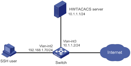
Configuration procedure
1. Configure the HWTACACS server:
# Set the shared keys to expert for secure communication with the switch. (Details not shown.)
# Add an account for the SSH user and specify the password. (Details not shown.)
2. Configure the switch:
# Configure IP addresses for the interfaces. (Details not shown.)
# Create an HWTACACS scheme.
<Switch> system-view
[Switch] hwtacacs scheme hwtac
# Specify the primary authentication server.
[Switch-hwtacacs-hwtac] primary authentication 10.1.1.1 49
# Specify the primary authorization server.
[Switch-hwtacacs-hwtac] primary authorization 10.1.1.1 49
# Specify the primary accounting server.
[Switch-hwtacacs-hwtac] primary accounting 10.1.1.1 49
# Set the shared keys to expert in plaintext form for secure HWTACACS communication.
[Switch-hwtacacs-hwtac] key authentication simple expert
[Switch-hwtacacs-hwtac] key authorization simple expert
[Switch-hwtacacs-hwtac] key accounting simple expert
# Exclude domain names from the usernames sent to the HWTACACS server.
[Switch-hwtacacs-hwtac] user-name-format without-domain
[Switch-hwtacacs-hwtac] quit
# Create an ISP domain named bbb and configure the domain to use the HWTACACS scheme for authentication, authorization, and accounting of login users.
[Switch-isp-bbb] authentication login hwtacacs-scheme hwtac
[Switch-isp-bbb] authorization login hwtacacs-scheme hwtac
[Switch-isp-bbb] accounting login hwtacacs-scheme hwtac
[Switch-isp-bbb] quit
# Create local RSA and DSA key pairs.
[Switch] public-key local create rsa
[Switch] public-key local create dsa
# Enable the SSH service.
[Switch] ssh server enable
# Enable scheme authentication for user lines VTY 0 through VTY 63.
[Switch] line vty 0 63
[Switch-line-vty0-63] authentication-mode scheme
[Switch-line-vty0-63] quit
# Enable the default user role feature to assign authenticated SSH users the default user role network-operator.
[Switch] role default-role enable
Verifying the configuration
# Initiate an SSH connection to the switch, and enter the correct username and password. The user logs in to the switch. (Details not shown.)
# Verify that the user can use the commands permitted by the network-operator user role. (Details not shown.)
Local authentication, HWTACACS authorization, and RADIUS accounting for SSH users
Network requirements
As shown in Figure 11, configure the switch to meet the following requirements:
· Perform local authentication for SSH servers.
· Use the HWTACACS server and RADIUS server for SSH user authorization and accounting, respectively.
· Exclude domain names from the usernames sent to the servers.
· Assign the default user role network-operator to SSH users after they pass authentication.
Configure an account with the username hello for the SSH user. Configure the shared keys to expert for secure communication with the HWTACACS server and RADIUS server.
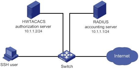
Configuration procedure
1. Configure the HWTACACS server. (Details not shown.)
2. Configure the RADIUS server. (Details not shown.)
3. Configure the switch:
# Configure IP addresses for interfaces. (Details not shown.)
# Create local RSA and DSA key pairs.
<Switch> system-view
[Switch] public-key local create rsa
[Switch] public-key local create dsa
# Enable the SSH service.
[Switch] ssh server enable
# Enable scheme authentication for user lines VTY 0 through VTY 63.
[Switch] line vty 0 63
[Switch-line-vty0-63] authentication-mode scheme
[Switch-line-vty0-63] quit
# Configure an HWTACACS scheme.
[Switch] hwtacacs scheme hwtac
[Switch-hwtacacs-hwtac] primary authorization 10.1.1.2 49
[Switch-hwtacacs-hwtac] key authorization simple expert
[Switch-hwtacacs-hwtac] user-name-format without-domain
[Switch-hwtacacs-hwtac] quit
# Configure a RADIUS scheme.
[Switch] radius scheme rd
[Switch-radius-rd] primary accounting 10.1.1.1 1813
[Switch-radius-rd] key accounting simple expert
[Switch-radius-rd] user-name-format without-domain
[Switch-radius-rd] quit
# Create a device management user.
[Switch] local-user hello class manage
# Assign the SSH service to the local user.
[Switch-luser-manage-hello] service-type ssh
# Set the password to 123456TESTplat&! in plaintext form for the local user. In FIPS mode, you must set the password in interactive mode.
[Switch-luser-manage-hello] password simple 123456TESTplat&!
[Switch-luser-manage-hello] quit
# Create an ISP domain named bbb and configure the login users to use local authentication, HWTACACS authorization, and RADIUS accounting.
[Switch] domain bbb
[Switch-isp-bbb] authentication login local
[Switch-isp-bbb] authorization login hwtacacs-scheme hwtac
[Switch-isp-bbb] accounting login radius-scheme rd
[Switch-isp-bbb] quit
# Enable the default user role feature to assign authenticated SSH users the default user role network-operator.
[Switch] role default-role enable
Verifying the configuration
# Initiate an SSH connection to the switch, and enter the username hello@bbb and the correct password. The user logs in to the switch. (Details not shown.)
# Verify that the user can use the commands permitted by the network-operator user role. (Details not shown.)
Authentication and authorization for SSH users by a RADIUS server
Network requirements
As shown in Figure 12, configure the switch to meet the following requirements:
· Use the RADIUS server for SSH user authentication and authorization.
· Include domain names in the usernames sent to the RADIUS server.
· Assign the default user role network-operator to SSH users after they pass authentication.
The RADIUS server runs on IMC. Add an account with the username hello@bbb on the RADIUS server.
The RADIUS server and the switch use expert as the shared key for secure RADIUS communication. The ports for authentication and accounting are 1812 and 1813, respectively.

Configuration procedure
1. Configure the RADIUS server on IMC 5.0:
|
|
NOTE: In this example, the RADIUS server runs on IMC PLAT 5.0 (E0101) and IMC UAM 5.0 (E0101). |
# Add the switch to the IMC Platform as an access device.
Log in to IMC, click the Service tab, and select User Access Manager > Access Device Management > Access Device from the navigation tree. Then, click Add to configure an access device as follows:
a. Set the shared key for secure RADIUS communication to expert.
b. Set the ports for authentication and accounting to 1812 and 1813, respectively.
c. Select the service type Device Management Service.
d. Select the access device type H3C.
e. Select the access device from the device list or manually add the access device (with the IP address 10.1.1.2).
f. Leave the default settings for other parameters and click OK.
The IP address of the access device specified here must be the same as the source IP address of the RADIUS packets sent from the switch. The source IP address is chosen in the following order on the switch:
? IP address specified by the nas-ip command.
? IP address specified by the radius nas-ip command.
? IP address of the outbound interface (the default).
Figure 13 Adding the switch as an access device
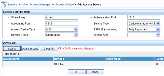
# Add an account for device management.
Click the User tab, and select Access User View > Device Mgmt User from the navigation tree. Then, click Add to configure a device management account as follows:
a. Enter the account name hello@bbb and specify the password.
b. Select the service type SSH.
c. Specify 10.1.1.0 to 10.1.1.255 as the IP address range of the hosts to be managed.
d. Click OK.
|
|
NOTE: The IP address range must contain the IP address of the switch. |
Figure 14 Adding an account for device management

2. Configure the switch:
# Configure the IP addresses for interfaces. (Details not shown.)
# Create local RSA and DSA key pairs.
<Switch> system-view
[Switch] public-key local create rsa
[Switch] public-key local create dsa
# Enable the SSH service.
[Switch] ssh server enable
# Enable scheme authentication for user lines VTY 0 through VTY 63.
[Switch] line vty 0 63
[Switch-line-vty0-63] authentication-mode scheme
[Switch-line-vty0-63] quit
# Enable the default user role feature to assign authenticated SSH users the default user role network-operator.
[Switch] role default-role enable
# Create a RADIUS scheme.
[Switch] radius scheme rad
# Specify the primary authentication server.
[Switch-radius-rad] primary authentication 10.1.1.1 1812
# Set the shared key to expert in plaintext form for secure communication with the server.
[Switch-radius-rad] key authentication simple expert
# Include domain names in the usernames sent to the RADIUS server.
[Switch-radius-rad] user-name-format with-domain
[Switch-radius-rad] quit
# Create an ISP domain named bbb and configure authentication, authorization, and accounting methods for login users.
[Switch] domain bbb
[Switch-isp-bbb] authentication login radius-scheme rad
[Switch-isp-bbb] authorization login radius-scheme rad
[Switch-isp-bbb] accounting login none
[Switch-isp-bbb] quit
Verifying the configuration
# Initiate an SSH connection to the switch, and enter the username hello@bbb and the correct password. The user logs in to the switch. (Details not shown.)
# Verify that the user can use the commands permitted by the network-operator user role. (Details not shown.)
Troubleshooting RADIUS
RADIUS authentication failure
Symptom
User authentication always fails.
Analysis
Possible reasons include:
· A communication failure exists between the NAS and the RADIUS server.
· The username is not in the userid@isp-name format, or the ISP domain is not correctly configured on the NAS.
· The user is not configured on the RADIUS server.
· The password entered by the user is incorrect.
· The RADIUS server and the NAS are configured with different shared keys.
Solution
To resolve the problem:
1. Verify the following items:
? The NAS and the RADIUS server can ping each other.
? The username is in the userid@isp-name format and the ISP domain is correctly configured on the NAS.
? The user is configured on the RADIUS server.
? The correct password is entered.
? The same shared key is configured on both the RADIUS server and the NAS.
2. If the problem persists, contact H3C Support.
RADIUS packet delivery failure
Symptom
RADIUS packets cannot reach the RADIUS server.
Analysis
Possible reasons include:
· A communication failure exists between the NAS and the RADIUS server.
· The NAS is not configured with the IP address of the RADIUS server.
· The authentication and accounting UDP ports configured on the NAS are incorrect.
· The RADIUS server's authentication and accounting port numbers are being used by other applications.
Solution
To resolve the problem:
1. Verify the following items:
? The link between the NAS and the RADIUS server works well at both the physical and data link layers.
? The IP address of the RADIUS server is correctly configured on the NAS.
? The authentication and accounting UDP port numbers configured on the NAS are the same as those of the RADIUS server.
? The RADIUS server's authentication and accounting port numbers are available.
2. If the problem persists, contact H3C Support.
RADIUS accounting error
Symptom
A user is authenticated and authorized, but accounting for the user is not normal.
Analysis
The accounting server configuration on the NAS is not correct. Possible reasons include:
· The accounting port number configured on the NAS is incorrect.
· The accounting server IP address configured on the NAS is incorrect. For example, the NAS is configured to use a single server to provide authentication, authorization, and accounting services, but in fact the services are provided by different servers.
Solution
To resolve the problem:
1. Verify the following items:
? The accounting port number is correctly configured.
? The accounting server IP address is correctly configured on the NAS.
2. If the problem persists, contact H3C Support.
Troubleshooting HWTACACS
Similar to RADIUS troubleshooting. See "Troubleshooting RADIUS."
Configuring password control
Overview
Password control allows you to implement the following features:
· Manage login and super password setup, expirations, and updates for device management users.
· Control user login status based on predefined policies.
Local users are divided into two types: device management users and network access users. This feature applies only to device management users. For more information about local users, see "Configuring AAA."
Password setting
Minimum password length
You can define the minimum length of user passwords. If a user enters a password that is shorter than the minimum length, the system rejects the password.
Password composition policy
A password can be a combination of characters from the following types:
· Uppercase letters A to Z.
· Lowercase letters a to z.
· Digits 0 to 9.
· Special characters in Table 5.
|
Character name |
Symbol |
Character name |
Symbol |
|
Ampersand sign |
& |
Apostrophe |
' |
|
Asterisk |
* |
At sign |
@ |
|
Back quote |
` |
Back slash |
\ |
|
Blank space |
N/A |
Caret |
^ |
|
Colon |
: |
Comma |
, |
|
Dollar sign |
$ |
Dot |
. |
|
Equal sign |
= |
Exclamation point |
! |
|
Left angle bracket |
< |
Left brace |
{ |
|
Left bracket |
[ |
Left parenthesis |
( |
|
Minus sign |
- |
Percent sign |
% |
|
Plus sign |
+ |
Pound sign |
# |
|
Quotation marks |
" |
Right angle bracket |
> |
|
Right brace |
} |
Right bracket |
] |
|
Right parenthesis |
) |
Semi-colon |
; |
|
Slash |
/ |
Tilde |
~ |
|
Underscore |
_ |
Vertical bar |
| |
Depending on the system's security requirements, you can set the minimum number of character types a password must contain and the minimum number of characters for each type, as shown in Table 6.
Table 6 Password composition policy
|
Password combination level |
Minimum number of character types |
Minimum number of characters for each type |
|
Level 1 |
One |
One |
|
Level 2 |
Two |
One |
|
Level 3 |
Three |
One |
|
Level 4 |
Four |
One |
In non-FIPS mode, all the combination levels are available for a password. In FIPS mode, only the level 4 combination is available for a password.
When a user sets or changes a password, the system checks if the password meets the combination requirement. If not, the operation fails.
Password complexity checking policy
A less complicated password such as a password containing the username or repeated characters is more likely to be cracked. For higher security, you can configure a password complexity checking policy to ensure that all user passwords are relatively complicated. With such a policy configured, when a user configures a password, the system checks the complexity of the password. If the password is complexity-incompliant, the configuration will fail.
You can apply the following password complexity requirements:
· A password cannot contain the username or the reverse of the username. For example, if the username is abc, a password such as abc982 or 2cba is not complex enough.
· A character or number cannot be included three or more times consecutively. For example, password a111 is not complex enough.
Password updating and expiration
Password updating
This feature allows you to set the minimum interval at which users can change their passwords. If a user logs in to change the password but the time passed since the last change is less than this interval, the system denies the request. For example, if you set this interval to 48 hours, a user cannot change the password twice within 48 hours.
The set minimum interval is not effective when a user is prompted to change the password at the first login or after its password aging time expires.
Password expiration
Password expiration imposes a lifecycle on a user password. After the password expires, the user needs to change the password.
If a user enters an expired password when logging in, the system displays an error message. The user is prompted to provide a new password and to confirm it by entering it again. The new password must be valid, and the user must enter exactly the same password when confirming it.
Telnet users, SSH users, and console users can change their own passwords. The administrator must change passwords for FTP users.
Early notice on pending password expiration
When a user logs in, the system checks whether the password will expire in a time equal to or less than the specified notification period. If so, the system notifies the user when the password will expire and provides a choice for the user to change the password. If the user sets a new password that is complexity-compliant, the system records the new password and the setup time. If the user chooses not to change the password or the user fails to change it, the system allows the user to log in using the current password.
Telnet users, SSH users, and console users can change their own passwords. The administrator must change passwords for FTP users.
Login with an expired password
You can allow a user to log in a certain number of times within a period of time after the password expires. For example, if you set the maximum number of logins with an expired password to 3 and the time period to 15 days, a user can log in three times within 15 days after the password expires.
Password history
With this feature enabled, the system stores passwords that a user has used. When a user changes the password, the system compares the new password with the current password and those stored in the password history records. The new password must be different from the current one and those stored in the history records by a minimum of four characters. The four characters must be different from one another. Otherwise, the system will display an error message, and the password will not be changed.
You can set the maximum number of history password records for the system to maintain for each user. When the number of history password records exceeds your setting, the most recent record overwrites the earliest one.
Current login passwords of device management users are not stored in the password history, because a device management user password is saved in cipher text and cannot be recovered to a plaintext password.
User login control
First login
If the global password control feature is enabled, users must change the password at first login before they can access the system. In this situation, password changes are not subject to the minimum password update interval.
Login attempt limit
Limiting the number of consecutive login failures can effectively prevent password guessing.
Login attempt limit takes effect on FTP and VTY users. It does not take effect on the following types of users:
· Nonexistent users (users not configured on the device).
· Users logging in to the device through console ports.
If a user fails to log in, the system adds the user account and the user's IP address to the password control blacklist. After making the maximum number of consecutive attempts, login attempt limit limits the user and user account in any of the following ways:
· Disables the user account until the account is manually removed from the password control blacklist.
· Allows the user to continue using the user account. The user's IP address and user account are removed from the password control blacklist when the user uses this account to successfully log in to the device.
· Disables the user account for a period of time.
The user can use the account to log in when either of the following conditions exists:
? The locking timer expires.
? The account is manually removed from the password control blacklist before the locking timer expires.
|
|
NOTE: This account is locked only for this user. Other users can still use this account, and the blacklisted user can use other user accounts. |
Maximum account idle time
You can set the maximum account idle time for user accounts. When an account is idle for this period of time since the last successful login, the account becomes invalid.
Password not displayed in any form
For security purposes, nothing is displayed when a user enters a password.
Logging
The system logs all successful password changing events and user adding events to the password control blacklist.
FIPS compliance
The device supports the FIPS mode that complies with NIST FIPS 140-2 requirements. Support for features, commands, and parameters might differ in FIPS mode (see "Configuring FIPS") and non-FIPS mode.
Password control configuration task list
The password control features can be configured in several different views, and different views support different features. The settings configured in different views or for different objects have the following application ranges:
· Settings for super passwords apply only to super passwords.
· Settings in local user view apply only to the password of the local user.
· Settings in user group view apply to the passwords of the local users in the user group if you do not configure password policies for these users in local user view.
· Global settings in system view apply to the passwords of the local users in all user groups if you do not configure password policies for these users in both local user view and user group view.
For local user passwords, the settings with a smaller application scope have higher priority.
To configure password control, perform the following tasks:
|
Tasks at a glance |
|
(Required.) Enabling password control |
|
(Optional.) Setting global password control parameters |
|
(Optional.) Setting user group password control parameters |
|
(Optional.) Setting local user password control parameters |
|
(Optional.) Setting super password control parameters |
Enabling password control
Enabling the global password control feature is the prerequisite for all password control configurations to take effect. Then, for a specific password control feature to take effect, enable this password control feature.
After the global password control feature is enabled, you cannot display the password and super password configurations for device management users by using the corresponding display commands. However, the configuration for network access user passwords can be displayed. The first password configured for device management users must contain a minimum of four different characters.
To ensure correct function of password control, configure the device to use NTP to obtain the UTC time. After global password control is enabled, password control will record the UTC time when the password is set. The recorded UTC time might not be consistent with the actual UTC time due to power failure or device reboot. The inconsistency will cause the password expiration feature to malfunction. For information about NTP, see Network Management and Monitoring Configuration Guide.
To enable password control:
|
Step |
Command |
Remarks |
|
system-view |
N/A |
|
|
2. Enable the global password control feature. |
password-control enable |
· In non-FIPS mode, the global password control feature is disabled by default. · In FIPS mode, the global password control feature is enabled, and cannot be disabled by default. |
|
3. (Optional.) Enable a specific password control feature. |
password-control { aging | composition | history | length } enable |
By default, all four password control features are enabled. |
Setting global password control parameters
The password expiration time, minimum password length, and password composition policy can be configured in system view, user group view, or local user view. The password settings with a smaller application scope have higher priority. Global settings in system view apply to the passwords of the local users in all user groups if you do not configure password policies for these users in both local user view and user group view.
The password-control login-attempt command takes effect immediately and can affect the users already in the password control blacklist. Other password control configurations do not take effect on users that have been logged in or passwords that have been configured.
To set global password control parameters:
|
Step |
Command |
Remarks |
|
1. Enter system view. |
system-view |
N/A |
|
2. Set the password expiration time. |
password-control aging aging-time |
The default setting is 90 days. |
|
3. Set the minimum password update interval. |
password-control update interval interval |
The default setting is 24 hours. |
|
4. Set the minimum password length. |
password-control length length |
· In non-FIPS mode, the default setting is 10 characters. · In FIPS mode, the default length is 15 characters. |
|
5. Configure the password composition policy. |
password-control composition type-number type-number [ type-length type-length ] |
The following default settings apply: · In non-FIPS mode, a password must contain a minimum of one character type and a minimum of one character for each type. · In FIPS mode, a password must contain a minimum of four character types and a minimum of one character for each type. |
|
6. Configure the password complexity checking policy. |
password-control complexity { same-character | user-name } check |
By default, the system does not perform password complexity checking. |
|
7. Set the maximum number of history password records for each user. |
password-control history max-record-number |
The default setting is 4. |
|
8. Configure the login attempt limit. |
password-control login-attempt login-times [ exceed { lock | lock-time time | unlock } ] |
By default, the maximum number of login attempts is 3 and a user failing to log in after the specified number of attempts must wait for 1 minute before trying again. |
|
9. Set the number of days during which a user is notified of the pending password expiration. |
password-control alert-before-expire alert-time |
The default setting is 7 days. |
|
10. Set the maximum number of days and maximum number of times that a user can log in after the password expires. |
password-control expired-user-login delay delay times times |
By default, a user can log in three times within 30 days after the password expires. |
|
11. Set the maximum account idle time. |
password-control login idle-time idle-time |
The default setting is 90 days. |
Setting user group password control parameters
|
Step |
Command |
Remarks |
|
1. Enter system view. |
system-view |
N/A |
|
2. Create a user group and enter its view. |
user-group group-name |
By default, no user groups exist. For information about how to configure a user group, see "Configuring AAA." |
|
3. Configure the password expiration time for the user group. |
password-control aging aging-time |
By default, the password expiration time of the user group equals the global password expiration time. |
|
4. Configure the minimum password length for the user group. |
password-control length length |
By default, the minimum password length of the user group equals the global minimum password length. |
|
5. Configure the password composition policy for the user group. |
password-control composition type-number type-number [ type-length type-length ] |
By default, the password composition policy of the user group equals the global password composition policy. |
|
6. Configure the password complexity checking policy for the user group. |
password-control complexity { same-character | user-name } check |
By default, the password complexity checking policy of the user group equals the global password complexity checking policy. |
|
7. Configure the login attempt limit. |
password-control login-attempt login-times [ exceed { lock | lock-time time | unlock } ] |
By default, the login-attempt policy of the user group equals the global login-attempt policy. |
Setting local user password control parameters
|
Step |
Command |
Remarks |
|
1. Enter system view. |
system-view |
N/A |
|
2. Create a device management user and enter its view. |
local-user user-name class manage |
By default, no local users exist. Local user password control applies to device management users instead of network access users. For information about how to configure a local user, see "Configuring AAA." |
|
3. Configure the password expiration time for the local user. |
password-control aging aging-time |
By default, the setting equals that for the user group to which the local user belongs. If no expiration time is configured for the user group, the global setting applies to the local user. |
|
4. Configure the minimum password length for the local user. |
password-control length length |
By default, the setting equals that for the user group to which the local user belongs. If no minimum password length is configured for the user group, the global setting applies to the local user. |
|
5. Configure the password composition policy for the local user. |
password-control composition type-number type-number [ type-length type-length ] |
By default, the settings equal those for the user group to which the local user belongs. If no password composition policy is configured for the user group, the global settings apply to the local user. |
|
6. Configure the password complexity checking policy for the local user. |
password-control complexity { same-character | user-name } check |
By default, the settings equal those for the user group to which the local user belongs. If no password complexity checking policy is configured for the user group, the global settings apply to the local user. |
|
7. Configure the login attempt limit. |
password-control login-attempt login-times [ exceed { lock | lock-time time | unlock } ] |
By default, the settings equal those for the user group to which the local user belongs. If no login-attempt policy is configured for the user group, the global settings apply to the local user. |
Setting super password control parameters
The super password allows you to obtain a temporary user role without reconnecting to the device. For more information, see Fundamentals Configuration Guide.
To set super password control parameters:
|
Step |
Command |
Remarks |
|
1. Enter system view. |
system-view |
N/A |
|
2. Set the password expiration time for super passwords. |
password-control super aging aging-time |
The default setting is 90 days. |
|
3. Configure the minimum length for super passwords. |
password-control super length length |
· In non-FIPS mode, the default setting is 10 characters. · In FIPS mode, the default setting is 15 characters. |
|
4. Configure the password composition policy for super passwords. |
password-control super composition type-number type-number [ type-length type-length ] |
The following default settings apply: · In non-FIPS mode, a super password must contain a minimum of one character type and a minimum of one character for each type. · In FIPS mode, a super password must contain a minimum of four character types and a minimum of one character for each type. |
Displaying and maintaining password control
Execute display commands in any view and reset commands in user view.
|
Task |
Command |
|
Display password control configuration. |
display password-control [ super ] |
|
Display information about users in the password control blacklist. |
display password-control blacklist [ user-name user-name | ip ipv4-address | ipv6 ipv6-address ] |
|
Delete users from the password control blacklist. |
reset password-control blacklist [ user-name user-name ] |
|
Clear history password records. |
reset password-control history-record [ user-name user-name | super [ role role name ] ] |
|
|
NOTE: The reset password-control history-record command can delete the history password records of one or all users even when the password history feature is disabled. |
Password control configuration example
Network requirements
Configure a global password control policy to meet the following requirements:
· A password must contain a minimum of 16 characters.
· A password must contain a minimum of four character types and a minimum of four characters for each type.
· An FTP or VTY user failing to provide the correct password in two successive login attempts is permanently prohibited from logging in.
· A user can log in five times within 60 days after the password expires.
· A password expires after 30 days.
· The minimum password update interval is 36 hours.
· The maximum account idle time is 30 days.
· A password cannot contain the username or the reverse of the username.
· No character appears consecutively three or more times in a password.
Configure a super password control policy for user role network-operator to meet the following requirements:
· A super password must contain a minimum of 24 characters.
· A super password must contain a minimum of four character types and a minimum of five characters for each type.
Configure a password control policy for local Telnet user test to meet the following requirements:
· The password must contain a minimum of 24 characters.
· The password must contain a minimum of four character types and a minimum of five characters for each type.
· The password for the local user expires after 20 days.
Configuration procedure
# Enable the password control feature globally.
<Sysname> system-view
[Sysname] password-control enable
# Disable a user account permanently if a user fails two consecutive login attempts on the user account.
[Sysname] password-control login-attempt 2 exceed lock
# Set all passwords to expire after 30 days.
[Sysname] password-control aging 30
# Globally set the minimum password length to 16 characters.
[Sysname] password-control length 16
# Set the minimum password update interval to 36 hours.
[Sysname] password-control update-interval 36
# Specify that a user can log in five times within 60 days after the password expires.
[Sysname] password-control expired-user-login delay 60 times 5
# Set the maximum account idle time to 30 days.
[Sysname] password-control login idle-time 30
# Refuse any password that contains the username or the reverse of the username.
[Sysname] password-control complexity user-name check
# Specify that no character can be included three or more times consecutively in a password.
[Sysname] password-control complexity same-character check
# Globally specify that all passwords must each contain a minimum of four character types and a minimum of four characters for each type.
[Sysname] password-control composition type-number 4 type-length 4
# Set the minimum super password length to 24 characters.
[Sysname] password-control super length 24
# Specify that a super password must contain a minimum of four character types and a minimum of five characters for each type.
[Sysname] password-control super composition type-number 4 type-length 5
# Configure a super password used for switching to user role network-operator as 123456789ABGFTweuix@#$%! in plain text.
[Sysname] super password role network-operator simple 123456789ABGFTweuix@#$%!
# Create a device management user named test.
[Sysname] local-user test class manage
# Set the service type of the user to Telnet.
[Sysname-luser-manage-test] service-type telnet
# Set the minimum password length to 24 for the local user.
[Sysname-luser-manage-test] password-control length 24
# Specify that the password of the local user must contain a minimum of four character types and a minimum of five characters for each type.
[Sysname-luser-manage-test] password-control composition type-number 4 type-length 5
# Set the password for the local user to expire after 20 days.
[Sysname-luser-manage-test] password-control aging 20
# Configure the password of the local user in interactive mode.
[Sysname-luser-manage-test] password
Password:
Confirm :
Updating user information. Please wait ... ...
[Sysname-luser-manage-test] quit
Verifying the configuration
# Display the global password control configuration.
<Sysname> display password-control
Global password control configurations:
Password control: Enabled
Password aging: Enabled (30 days)
Password length: Enabled (16 characters)
Password composition: Enabled (4 types, 4 characters per type)
Password history: Enabled (max history record:4)
Early notice on password expiration: 7 days
Maximum login attempts: 2
Action for exceeding login attempts: Lock
Minimum interval between two updates: 36 hours
User account idle time: 30 days
Logins with aged password: 5 times in 60 days
Password complexity: Enabled (username checking)
Enabled (repeated characters checking)
# Display the password control configuration for super passwords.
<Sysname> display password-control super
Super password control configurations:
Password aging: Enabled (90 days)
Password length: Enabled (24 characters)
Password composition: Enabled (4 types, 5 characters per type)
# Display the password control configuration for local user test.
<Sysname> display local-user user-name test class manage
Total 1 local users matched.
Device management user test:
State: Active
Service type: Telnet
User group: system
Bind attributes:
Authorization attributes:
Work directory: flash:
User role list: network-operator
Password control configurations:
Password aging: 20 days
Password length: 24 characters
Password composition: 4 types, 5 characters per type
Configuring keychains
Overview
A keychain, a sequence of keys, provides dynamic authentication to ensure secure communication by periodically changing the key and authentication algorithm without service interruption.
Each key in a keychain has a key string, authentication algorithm, sending lifetime, and receiving lifetime. These settings can be different for the keys. When the system time is within the lifetime of a key in a keychain, an application uses the key to authenticate incoming and outgoing packets. The keys in the keychain take effect one by one according to the sequence of the configured lifetimes. In this way, the authentication algorithms and keys are dynamically changed to implement dynamic authentication.
A keychain operates in absolute time mode. In this mode, each time point during a key's lifetime is the UTC time and is not affected by the system's time zone or daylight saving time.
Configuration procedure
Follow these guidelines when you configure a keychain:
· To make sure only one key in a keychain is used at a time to authenticate packets to a peer, set non-overlapping sending lifetimes for the keys in the keychain.
· The keys used by the local device and the peer device must have the same authentication algorithm and key string.
|
Step |
Command |
Remarks |
|
1. Enter system view. |
system-view |
N/A |
|
2. Create a keychain and enter keychain view. |
keychain keychain-name [ mode absolute ] |
By default, no keychains exist. |
|
3. (Optional.) Set the kind value in the TCP Enhanced Authentication Option. |
tcp-kind kind-value |
By default, the kind value is 254. When the local device uses TCP to communicate with a peer device from another vendor, make sure both devices have the same kind value setting. If they do not have the same value, use this command to modify the kind value on the local device. |
|
4. (Optional.) Set an algorithm ID for a TCP authentication algorithm. |
tcp-algorithm-id { hmac-md5 | md5 } algorithm-id |
By default, the algorithm ID is 3 for the MD5 authentication algorithm, and is 5 for the HMAC-MD5 authentication algorithm. When the local device uses TCP to communicate with a peer device from another vendor, make sure both devices have the same algorithm ID setting. If they do not have the same algorithm ID, use this command to modify the algorithm ID on the local device. |
|
5. (Optional.) Set a tolerance time for accept keys in the keychain. |
accept-tolerance { value | infinite } |
By default, no tolerance time is configured for accept keys in a keychain. |
|
6. Create a key and enter key view. |
key key-id |
By default, no keys exist. |
|
7. Specify an authentication algorithm for the key. |
authentication-algorithm { hmac-md5 | hmac-sha-256 | md5 } |
By default, no authentication algorithm is specified for a key. |
|
8. Configure a key string for the key. |
key-string { cipher | plain } string |
By default, no key string is configured. |
|
9. Set the sending lifetime in UTC mode for the key. |
send-lifetime utc start-time start-date { duration { duration-value | infinite } | to end-time end-date } |
By default, the sending lifetime is not configured for a key. |
|
10. Set the receiving lifetime in UTC mode for the key. |
accept-lifetime utc start-time start-date { duration { duration-value | infinite } | to end-time end-date } |
By default, the receiving lifetime is not configured for a key. |
|
11. (Optional.) Specify the key as the default send key. |
default-send-key |
By default, no key in a keychain is specified as the default send key. |
Displaying and maintaining keychain
Execute display commands in any view.
|
Task |
Command |
|
Display keychain information. |
display keychain [ name keychain-name [ key key-id ] ] |
Keychain configuration example
Network requirements
As shown in Figure 15, establish an OSPF neighbor relationship between Switch A and Switch B, and use a keychain to authenticate packets between the switches. Configure key 1 and key 2 for the keychain and make sure key 2 is used immediately when key 1 expires.
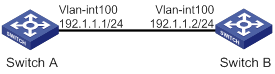
Configuration procedure
Configuring Switch A
# Configure IP addresses for interfaces. (Details not shown.)
# Configure OSPF.
<SwitchA> system-view
[SwitchA] ospf 1 router-id 1.1.1.1
[SwitchA-ospf-1] area 0
[SwitchA-ospf-1-area-0.0.0.0] network 192.1.1.0 0.0.0.255
[SwitchA-ospf-1-area-0.0.0.0] quit
[SwitchA-ospf-1] quit
# Create a keychain named abc, and specify the absolute time mode for it.
[SwitchA] keychain abc mode absolute
# Create key 1 for keychain abc, specify an authentication algorithm, and configure a key string and the sending and receiving lifetimes for the key.
[SwitchA-keychain-abc] key 1
[SwitchA-keychain-abc-key-1] authentication-algorithm md5
[SwitchA-keychain-abc-key-1] key-string plain 123456
[SwitchA-keychain-abc-key-1] send-lifetime utc 10:00:00 2015/02/06 to 11:00:00 2015/02/06
[SwitchA-keychain-abc-key-1] accept-lifetime utc 10:00:00 2015/02/06 to 11:00:00 2015/02/06
[SwitchA-keychain-abc-key-1] quit
# Create key 2 for keychain abc, specify an authentication algorithm, and configure a key string and the sending and receiving lifetimes for the key.
[SwitchA-keychain-abc] key 2
[SwitchA-keychain-abc-key-2] authentication-algorithm hmac-md5
[SwitchA-keychain-abc-key-2] key-string plain pwd123
[SwitchA-keychain-abc-key-2] send-lifetime utc 11:00:00 2015/02/06 to 12:00:00 2015/02/06
[SwitchA-keychain-abc-key-2] accept-lifetime utc 11:00:00 2015/02/06 to 12:00:00 2015/02/06
[SwitchA-keychain-abc-key-2] quit
[SwitchA-keychain-abc] quit
# Configure VLAN-interface 100 to use keychain abc for authentication.
[SwitchA] interface vlan-interface 100
[SwitchA-Vlan-interface100] ospf authentication-mode keychain abc
[SwitchA-Vlan-interface100] quit
Configuring Switch B
# Configure IP addresses for interfaces. (Details not shown.)
# Configure OSPF.
[SwitchB] ospf 1 router-id 2.2.2.2
[SwitchB-ospf-1] area 0
[SwitchB-ospf-1-area-0.0.0.0] network 192.1.1.0 0.0.0.255
[SwitchB-ospf-1-area-0.0.0.0] quit
[SwitchB-ospf-1] quit
# Create a keychain named abc, and specify the absolute time mode for it.
[SwitchB] keychain abc mode absolute
# Create key 1 for keychain abc, specify an authentication algorithm, and configure a key string and the sending and receiving lifetimes for the key.
[SwitchB-keychain-abc] key 1
[SwitchB-keychain-abc-key-1] authentication-algorithm md5
[SwitchB-keychain-abc-key-1] key-string plain 123456
[SwitchB-keychain-abc-key-1] send-lifetime utc 10:00:00 2015/02/06 to 11:00:00 2015/02/06
[SwitchB-keychain-abc-key-1] accept-lifetime utc 10:00:00 2015/02/06 to 11:00:00 2015/02/06
[SwitchB-keychain-abc-key-1] quit
# Create key 2 for keychain abc, specify an authentication algorithm, and configure a key string and the sending and receiving lifetimes for the key.
[SwitchB-keychain-abc] key 2
[SwitchB-keychain-abc-key-2] authentication-algorithm hmac-md5
[SwitchB-keychain-abc-key-2] key-string plain pwd123
[SwitchB-keychain-abc-key-2] send-lifetime utc 11:00:00 2015/02/06 to 12:00:00 2015/02/06
[SwitchB-keychain-abc-key-2] accept-lifetime utc 11:00:00 2015/02/06 to 12:00:00 2015/02/06
[SwitchB-keychain-abc-key-2] quit
[SwitchB-keychain-abc] quit
# Configure VLAN-interface 100 to use keychain abc for authentication.
[SwitchB] interface vlan-interface 100
[SwitchB-Vlan-interface100] ospf authentication-mode keychain abc
[SwitchB-Vlan-interface100] quit
Verifying the configuration
1. When the system time is within the lifetime from 10:00:00 to 11:00:00 on the day 2015/02/06, verify the status of the keys in keychain abc.
# Display keychain information on Switch A. The output shows that key 1 is the valid key.
[SwitchA] display keychain
Keychain name : abc
Mode : absolute
Accept tolerance : 0
TCP kind value : 254
TCP algorithm value
HMAC-MD5 : 5
MD5 : 3
Default send key ID : None
Active send key ID : 1
Active accept key IDs: 1
Key ID : 1
Key string : $c$3$dYTC8QeOKJkwFwP2k/rWL+1p6uMTw3MqNg==
Algorithm : md5
Send lifetime : 10:00:00 2015/02/06 to 11:00:00 2015/02/06
Send status : Active
Accept lifetime : 10:00:00 2015/02/06 to 11:00:00 2015/02/06
Accept status : Active
Key ID : 2
Key string : $c$3$7TSPbUxoP1ytOqkdcJ3K3x0BnXEWl4mOEw==
Algorithm : hmac-md5
Send lifetime : 11:00:00 2015/02/06 to 12:00:00 2015/02/06
Send status : Inactive
Accept lifetime : 11:00:00 2015/02/06 to 12:00:00 2015/02/06
Accept status : Inactive
# Display keychain information on Switch B. The output shows that key 1 is the valid key.
[SwitchB]display keychain
Keychain name : abc
Mode : absolute
Accept tolerance : 0
TCP kind value : 254
TCP algorithm value
HMAC-MD5 : 5
MD5 : 3
Default send key ID : None
Active send key ID : 1
Active accept key IDs: 1
Key ID : 1
Key string : $c$3$/G/Shnh6heXWprlSQy/XDmftHa2JZJBSgg==
Algorithm : md5
Send lifetime : 10:00:00 2015/02/06 to 11:00:00 2015/02/06
Send status : Active
Accept lifetime : 10:00:00 2015/02/06 to 11:00:00 2015/02/06
Accept status : Active
Key ID : 2
Key string : $c$3$t4qHAw1hpZYN0JKIEpXPcMFMVT81u0hiOw==
Algorithm : hmac-md5
Send lifetime : 11:00:00 2015/02/06 to 12:00:00 2015/02/06
Send status : Inactive
Accept lifetime : 11:00:00 2015/02/06 to 12:00:00 2015/02/06
Accept status : Inactive
2. When the system time is within the lifetime from 11:00:00 to 12:00:00 on the day 2015/02/06, verify the status of the keys in keychain abc.
# Display keychain information on Switch A. The output shows that key 2 becomes the valid key.
[SwitchA]display keychain
Keychain name : abc
Mode : absolute
Accept tolerance : 0
TCP kind value : 254
TCP algorithm value
HMAC-MD5 : 5
MD5 : 3
Default send key ID : None
Active send key ID : 2
Active accept key IDs: 2
Key ID : 1
Key string : $c$3$dYTC8QeOKJkwFwP2k/rWL+1p6uMTw3MqNg==
Algorithm : md5
Send lifetime : 10:00:00 2015/02/06 to 11:00:00 2015/02/06
Send status : Inactive
Accept lifetime : 10:00:00 2015/02/06 to 11:00:00 2015/02/06
Accept status : Inactive
Key ID : 2
Key string : $c$3$7TSPbUxoP1ytOqkdcJ3K3x0BnXEWl4mOEw==
Algorithm : hmac-md5
Send lifetime : 11:00:00 2015/02/06 to 12:00:00 2015/02/06
Send status : Active
Accept lifetime : 11:00:00 2015/02/06 to 12:00:00 2015/02/06
Accept status : Active
# Display keychain information on Switch B. The output shows that key 2 becomes the valid key.
[SwitchB]display keychain
Keychain name : abc
Mode : absolute
Accept tolerance : 0
TCP kind value : 254
TCP algorithm value
HMAC-MD5 : 5
MD5 : 3
Default send key ID : None
Active send key ID : 1
Active accept key IDs: 1
Key ID : 1
Key string : $c$3$/G/Shnh6heXWprlSQy/XDmftHa2JZJBSgg==
Algorithm : md5
Send lifetime : 10:00:00 2015/02/06 to 11:00:00 2015/02/06
Send status : Inactive
Accept lifetime : 10:00:00 2015/02/06 to 11:00:00 2015/02/06
Accept status : Inactive
Key ID : 2
Key string : $c$3$t4qHAw1hpZYN0JKIEpXPcMFMVT81u0hiOw==
Algorithm : hmac-md5
Send lifetime : 11:00:00 2015/02/06 to 12:00:00 2015/02/06
Send status : Active
Accept lifetime : 11:00:00 2015/02/06 to 12:00:00 2015/02/06
Accept status : Active
Managing public keys
Overview
This chapter describes public key management for the following asymmetric key algorithms:
· Revest-Shamir-Adleman Algorithm (RSA).
· Digital Signature Algorithm (DSA).
· Elliptic Curve Digital Signature Algorithm (ECDSA).
Many security applications (for example, SSH) use asymmetric key algorithms to secure communications between two parties, as shown in Figure 16. Asymmetric key algorithms use two separate keys (one public and one private) for encryption and decryption. Symmetric key algorithms use only one key.
Figure 16 Encryption and decryption
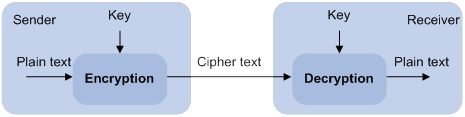
A key owner can distribute the public key in plain text on the network but must keep the private key in privacy. It is mathematically infeasible to calculate the private key even if an attacker knows the algorithm and the public key.
The security applications use the asymmetric key algorithms for the following purposes:
· Encryption and decryption—Any public key receiver can use the public key to encrypt information, but only the private key owner can decrypt the information.
· Digital signature—The key owner uses the private key to digitally sign information to be sent. The receiver decrypts the information with the sender's public key to verify information authenticity.
RSA, DSA, and ECDSA can all perform digital signature, but only RSA can perform encryption and decryption.
Asymmetric key algorithms enable secure key distribution on an insecure network. The security strength of an asymmetric key varies by the key modulus length as with any symmetric key algorithm.
FIPS compliance
The device supports the FIPS mode that complies with NIST FIPS 140-2 requirements. Support for features, commands, and parameters might differ in FIPS mode (see "Configuring FIPS") and non-FIPS mode.
Creating a local key pair
When you create a local key pair, follow these guidelines:
· The key algorithm must be the same as required by the security application.
· When you create an RSA or DSA key pair, enter an appropriate key modulus length at the prompt. The longer the key modulus length, the higher the security, and the longer the key generation time.
When you create an ECDSA key pair, choose the appropriate elliptic curve. The elliptic curve determines the ECDSA key length. The longer the key length, the higher the security, and the longer the key generation time.
See Table 7 for more information about key modulus lengths and key lengths.
· If you do not assign the key pair a name, the system assigns the default name to the key pair and marks the key pair as default. You can also assign the default name to another key pair, but the system does not mark the key pair as default. The key pair name must be unique among all manually named key pairs that use the same key algorithm. If a name conflict occurs, the system asks whether you want to overwrite the existing key pair.
· The key pairs are automatically saved and can survive system reboots.
Table 7 A comparison of different types of asymmetric key algorithms
|
Type |
Generated key pairs |
Modulus/key length |
|
RSA |
· In non-FIPS mode: ? One host key pair, if you specify a key pair name. ? One
server key pair and one host key pair, if you do not specify a key pair name. · In FIPS mode: One host key pair. NOTE: Only SSH 1.5 uses the RSA server key pair. |
·
In non-FIPS mode: 512 to 2048 bits, 1024 bits
by default. · In FIPS mode: 2048 bits. |
|
DSA |
One host key pair. |
·
In non-FIPS mode: 512 to 2048 bits, 1024 bits. · In FIPS mode: 2048 bits. |
|
ECDSA |
One host key pair. |
· In non-FIPS mode: 192, 256, 384, or 521 bits. · In FIPS mode: 256, 384, or 521 bits. |
To create a local key pair:
|
Step |
Command |
Remarks |
|
1. Enter system view. |
system-view |
N/A |
|
2. Create a local key pair. |
·
In non-FIPS mode: ·
In FIPS mode: |
By default, no local key pairs exist. |
Distributing a local host public key
For applications such as SSH, you must distribute a local host public key to a peer device so the peer device can perform the following operations:
· Use the public key to encrypt information sent to the local device.
· Authenticate the digital signature signed by the local device.
To distribute a local host public key, you must first export or display the key.
· Export a host public key:
? Export a host public key to a file.
? Export a host public key to the monitor screen, and then save it to a file.
After the key is exported to a file, transfer the file to the peer device. On the peer device, import the key from the file.
· Display a host public key.
After the key is displayed, record the key, for example, copy it to an unformatted file. On the peer device, you must literally enter the key.
Exporting a host public key
When you export a host public key, follow these restrictions and guidelines:
· If you specify a file name in the command, the command exports the key to the specified file.
· If you do not specify a file name, the command exports the key to the monitor screen. You must manually save the exported key to a file.
To export a local host public key:
|
Step |
Command |
|
1. Enter system view. |
system-view |
|
2. Export a local host public key. |
· Export an RSA host public key: ? In
non-FIPS mode: ? In FIPS mode: ·
Export an ECDSA host public key: ·
Export a DSA host public key: |
Displaying a host public key
Perform the following tasks in any view:
|
Task |
Command |
|
Display local RSA public keys. |
display public-key local rsa public [ name key-name ] |
|
Display local ECDSA public keys. |
display public-key local ecdsa public [ name key-name ] |
|
Display local DSA public keys. |
display public-key local dsa public [ name key-name ] |
|
|
NOTE: Do not distribute the RSA server public key serverkey (default) to a peer device. |
Destroying a local key pair
To avoid key compromise, destroy the local key pair and generate a new pair after any of the following conditions occurs:
· An intrusion event has occurred.
· The storage media of the device is replaced.
To destroy a local key pair:
|
Step |
Command |
|
1. Enter system view. |
system-view |
|
2. Destroy a local key pair. |
public-key local destroy { dsa | ecdsa | rsa } [ name key-name ] |
Configuring a peer host public key
To encrypt information sent to a peer device or authenticate the digital signature of the peer device, you must configure the peer device's public key on the local device.
You can configure the peer host public key by using the following methods:
· Import the peer host public key from a public key file (recommended).
· Manually enter (type or copy) the peer host public key.
Importing a peer host public key from a public key file
Before you perform this task, make sure you have exported the host public key to a file on the peer device and obtained the file from the peer device. For information about exporting a host public key, see "Exporting a host public key."
After you import the key, the system automatically converts the imported public key to a string in the Public Key Cryptography Standards (PKCS) format.
To import a peer host public key from a public key file:
|
Step |
Command |
Remarks |
|
1. Enter system view. |
system-view |
N/A |
|
2. Import a peer host public key from a public key file. |
public-key peer keyname import sshkey filename |
By default, no peer host public keys exist. |
Entering a peer host public key
Before you perform this task, make sure you have displayed the key on the peer device and recorded the key. For information about displaying a host public key, see "Displaying a host public key."
Use the display public-key local public command to display the public key on the peer device. The format of the public key displayed in any other way might be incorrect. If the key is not in the correct format, the system discards the key and displays an error message. If the key is valid, the system saves the key.
Always import rather than enter the peer host public key if you are not sure whether the device supports the format of the recorded peer host public key.
To enter a peer host public key:
|
Step |
Command |
Remarks |
|
1. Enter system view. |
system-view |
N/A |
|
2. Specify a name for the peer host public key and enter public key view. |
public-key peer keyname |
By default, no peer host public keys exist. |
|
3. Type or copy the key. |
N/A |
You can use spaces and carriage returns, but the system does not save them. |
|
4. Return to system view. |
peer-public-key end |
When you exit public key view, the system automatically saves the peer host public key. |
Displaying and maintaining public keys
Execute display commands in any view.
|
Task |
Command |
|
Display local public keys. |
display public-key local { dsa | ecdsa | rsa } public [ name key-name ] |
|
Display peer host public keys. |
display public-key peer [ brief | name publickey-name ] |
Examples of public key management
Example for entering a peer host public key
Network requirements
As shown in Figure 17, to prevent illegal access, Device B authenticates Device A through a digital signature. Before configuring authentication parameters on Device B, configure the public key of Device A on Device B.
· Configure Device B to use the asymmetric key algorithm of RSA to authenticate Device A.
· Manually specify the host public key of Device A on Device B.
Configuration procedure
1. Configure Device A:
# Create local RSA key pairs with default names on Device A, and use the default modulus length 1024 bits.
<DeviceA> system-view
[DeviceA] public-key local create rsa
The range of public key modulus is (512 ~ 2048).
If the key modulus is greater than 512, it will take a few minutes.
Press CTRL+C to abort.
Input the modulus length [default = 1024]:
Generating Keys...
.................++++++
......................................++++++
.....++++++++
..............++++++++
Create the key pair successfully.
# Display all local RSA public keys.
[DeviceA] display public-key local rsa public
=============================================
Key name: hostkey (default)
Key type: RSA
Time when key pair created: 16:48:31 2011/05/12
Key code:
30819F300D06092A864886F70D010101050003818D0030818902818100DA3B90F59237347B
8D41B58F8143512880139EC9111BFD31EB84B6B7C7A1470027AC8F04A827B30C2CAF79242E
45FDFF51A9C7E917DB818D54CB7AEF538AB261557524A7441D288EC54A5D31EFAE4F681257
6D7796490AF87A8C78F4A7E31F0793D8BA06FB95D54EBB9F94EB1F2D561BF66EA27DFD4788
CB47440AF6BB25ACA50203010001
=============================================
Key name: serverkey (default)
Key type: RSA
Time when key pair created: 16:48:31 2011/05/12
Key code:
307C300D06092A864886F70D0101010500036B003068026100C9451A80F7F0A9BA1A90C7BC
1C02522D194A2B19F19A75D9EF02219068BD7FD90FCC2AF3634EEB9FA060478DD0A1A49ACE
E1362A4371549ECD85BA04DEE4D6BB8BE53B6AED7F1401EE88733CA3C4CED391BAE633028A
AC41C80A15953FB22AA30203010001
2. Configure Device B:
# Enter the host public key of Device A in public key view. The key must be literally the same as displayed on Device A.
<DeviceB> system-view
[DeviceB] public-key peer devicea
Enter public key view. Return to system view with "peer-public-key end" command.
[DeviceB-pkey-public-key-devicea]30819F300D06092A864886F70D010101050003818D003081890
2818100DA3B90F59237347B
[DeviceB-pkey-public-key-devicea]8D41B58F8143512880139EC9111BFD31EB84B6B7C7A1470027A
C8F04A827B30C2CAF79242E
[DeviceB-pkey-public-key-devicea]45FDFF51A9C7E917DB818D54CB7AEF538AB261557524A7441D2
88EC54A5D31EFAE4F681257
[DeviceB-pkey-public-key-devicea]6D7796490AF87A8C78F4A7E31F0793D8BA06FB95D54EBB9F94E
B1F2D561BF66EA27DFD4788
[DeviceB-pkey-public-key-devicea]CB47440AF6BB25ACA50203010001
# Save the public key and return to system view.
[DeviceB-pkey-public-key-devicea] peer-public-key end
Verifying the configuration
# Verify that the peer host public key configured on Device B is the same as the key displayed on Device A.
[DeviceB] display public-key peer name devicea
=============================================
Key name: devicea
Key type: RSA
Key modulus: 1024
Key code:
30819F300D06092A864886F70D010101050003818D0030818902818100DA3B90F59237347B
8D41B58F8143512880139EC9111BFD31EB84B6B7C7A1470027AC8F04A827B30C2CAF79242E
45FDFF51A9C7E917DB818D54CB7AEF538AB261557524A7441D288EC54A5D31EFAE4F681257
6D7796490AF87A8C78F4A7E31F0793D8BA06FB95D54EBB9F94EB1F2D561BF66EA27DFD4788
CB47440AF6BB25ACA50203010001
Example for importing a public key from a public key file
Network requirements
As shown in Figure 18, Device B authenticates Device A through a digital signature. Before configuring authentication parameters on Device B, configure the public key of Device A on Device B.
· Configure Device B to use the asymmetric key algorithm of RSA to authenticate Device A.
· Import the host public key of Device A from the public key file to Device B.
Configuration procedure
1. Configure Device A:
# Create local RSA key pairs with default names on Device A, and use the default modulus length 1024 bits.
<DeviceA> system-view
[DeviceA] public-key local create rsa
The range of public key modulus is (512 ~ 2048).
If the key modulus is greater than 512, it will take a few minutes.
Press CTRL+C to abort.
Input the modulus length [default = 1024]:
Generating Keys...
.................++++++
......................................++++++
.....++++++++
..............++++++++
Create the key pair successfully.
# Display all local RSA public keys.
[DeviceA] display public-key local rsa public
=============================================
Key name: hostkey (default)
Key type: RSA
Time when key pair created: 16:48:31 2011/05/12
Key code:
30819F300D06092A864886F70D010101050003818D0030818902818100DA3B90F59237347B
8D41B58F8143512880139EC9111BFD31EB84B6B7C7A1470027AC8F04A827B30C2CAF79242E
45FDFF51A9C7E917DB818D54CB7AEF538AB261557524A7441D288EC54A5D31EFAE4F681257
6D7796490AF87A8C78F4A7E31F0793D8BA06FB95D54EBB9F94EB1F2D561BF66EA27DFD4788
CB47440AF6BB25ACA50203010001
=============================================
Key name: serverkey (default)
Key type: RSA
Time when key pair created: 16:48:31 2011/05/12
Key code:
307C300D06092A864886F70D0101010500036B003068026100C9451A80F7F0A9BA1A90C7BC
1C02522D194A2B19F19A75D9EF02219068BD7FD90FCC2AF3634EEB9FA060478DD0A1A49ACE
E1362A4371549ECD85BA04DEE4D6BB8BE53B6AED7F1401EE88733CA3C4CED391BAE633028A
AC41C80A15953FB22AA30203010001
# Export the RSA host public key to the file devicea.pub.
[DeviceA] public-key local export rsa ssh2 devicea.pub
# Enable the FTP server function, create an FTP user with the username ftp and password 123, and configure the FTP user role as network-admin.
[DeviceA] ftp server enable
[DeviceA] local-user ftp
[DeviceA-luser-manage-ftp] password simple 123
[DeviceA-luser-manage-ftp] service-type ftp
[DeviceA-luser-manage-ftp] authorization-attribute user-role network-admin
[DeviceA-luser-manage-ftp] quit
2. Configure Device B:
# Use FTP in binary mode to get the public key file devicea.pub from Device A.
<DeviceB> ftp 10.1.1.1
Connected to 10.1.1.1 (10.1.1.1).
220 FTP service ready.
User(10.1.1.1:(none)):ftp
331 Password required for ftp.
Password:
230 User logged in.
Remote system type is UNIX.
Using binary mode to transfer files.
ftp> binary
200 TYPE is now 8-bit binary
ftp> get devicea.pub
227 Entering Passive Mode (10,1,1,1,118,252)
150 Accepted data connection
226 File successfully transferred
301 bytes received in 0.003 seconds (98.0 kbyte/s)
ftp> quit
221-Goodbye. You uploaded 0 and downloaded 1 kbytes.
221 Logout.
# Import the host public key from the key file devicea.pub.
<DeviceB> system-view
[DeviceB] public-key peer devicea import sshkey devicea.pub
Verifying the configuration
# Verify that the peer host public key configured on Device B is the same as the key displayed on Device A.
[DeviceB] display public-key peer name devicea
=============================================
Key name: devicea
Key type: RSA
Key modulus: 1024
Key code:
30819F300D06092A864886F70D010101050003818D0030818902818100DA3B90F59237347B
8D41B58F8143512880139EC9111BFD31EB84B6B7C7A1470027AC8F04A827B30C2CAF79242E
45FDFF51A9C7E917DB818D54CB7AEF538AB261557524A7441D288EC54A5D31EFAE4F681257
6D7796490AF87A8C78F4A7E31F0793D8BA06FB95D54EBB9F94EB1F2D561BF66EA27DFD4788
CB47440AF6BB25ACA50203010001
Configuring SSH
Overview
Secure Shell (SSH) is a network security protocol. Using encryption and authentication, SSH can implement secure remote access and file transfer over an insecure network.
SSH uses the typical client-server model to establish a channel for secure data transfer based on TCP.
SSH includes two versions: SSH1.x and SSH2.0 (hereinafter referred to as SSH1 and SSH2), which are not compatible. SSH2 is better than SSH1 in performance and security.
The device supports the following SSH applications:
· Secure Telnet—Stelnet provides secure and reliable network terminal access services. Through Stelnet, a user can securely log in to a remote server. Stelnet can protect devices against attacks, such as IP spoofing and plain text password interception. The device can act as an Stelnet server or an Stelnet client.
· Secure File Transfer Protocol—Based on SSH2, SFTP uses SSH connections to provide secure file transfer. The device can act as an SFTP server, allowing a remote user to log in to the SFTP server for secure file management and transfer. The device can also act as an SFTP client, enabling a user to log in from the device to a remote device for secure file transfer.
· Secure Copy—Based on SSH2, SCP offers a secure method to copy files. The device can act as an SCP server, allowing a user to log in to the device for file upload and download. The device can also act as an SCP client, enabling a user to log in from the device to a remote device for secure file transfer.
· NETCONF over SSH—Based on SSH2, it enables users to securely log in to the device through SSH and perform NETCONF operations on the device through the NETCONF-over-SSH connections. The device can act only as a NETCONF-over-SSH server. For more information about NETCONF, see Network Management and Monitoring Configuration Guide.
When acting as an SSH client or server, the device supports the following SSH versions:
· When acting as an SSH client, the device supports only SSH2.
· When acting as an Stelnet, SFTP, or SCP server, the device supports both SSH2 and SSH1 in non-FIPS mode and only SSH2 in FIPS mode.
· When acting as a NETCONF-over-SSH server, the device supports only SSH2.
How SSH works
This section uses SSH2 as an example to describe the stages to establish an SSH session. For more information about these stages, see SSH Technology White Paper.
Table 8 Stages to establish an SSH session
|
Stages |
Description |
|
Connection establishment |
The SSH server listens to connection requests on port 22. After a client initiates a connection request, the server and the client establish a TCP connection. |
|
Version negotiation |
The two parties determine a version to use. |
|
Algorithm negotiation |
SSH supports multiple algorithms. Based on the local algorithms, the two parties negotiate the following algorithms: · Key exchange algorithm for generating session keys. · Encryption algorithm for encrypting data. · Public key algorithm for the digital signature and authentication. · HMAC algorithm for protecting data integrity. |
|
Key exchange |
The two parties use the DH exchange algorithm to dynamically generate the session keys and session ID. · The session keys are used for protecting data transfer. · The session ID is used for identifying the SSH connection. In this stage, the client also authenticates the server. |
|
Authentication |
The SSH server authenticates the client in response to the client's authentication request. |
|
Session request |
After passing the authentication, the client sends a session request to the server to request the establishment of a session (or request the Stelnet, SFTP, SCP, or NETCONF service). |
|
Interaction |
After the server grants the request, the client and the server start to communicate with each other in the session. In this stage, you can paste commands in text format and execute them at the CLI. The text pasted at one time must be no more than 2000 bytes. As a best practice to ensure the correct execution of commands, paste commands that are in the same view. To execute commands of more than 2000 bytes, save the commands in a configuration file, upload the file to the server through SFTP, and use it to restart the server. |
SSH authentication methods
This section describes authentication methods that are supported by the device when it acts as an SSH server.
Password authentication
The SSH server authenticates a client through the AAA mechanism. The password authentication process is as follows:
1. The client sends the server an authentication request that includes the encrypted username and password.
2. The server performs the following operations:
a. Decrypts the request to get the username and password in plain text.
b. Verifies the username and password locally or through remote AAA authentication.
c. Informs the client of the authentication result.
If the remote AAA server requires the user to enter a password for secondary authentication, it send the SSH server an authentication response carrying a prompt. The prompt is transparently transmitted to the client to notify the user to enter a specific password. When the user enters the correct password, the AAA server examines the password validity. If the password is valid, the SSH server returns an authentication success message to the client.
For more information about AAA, see "Configuring AAA."
|
|
NOTE: SSH1 clients do not support secondary password authentication that is initiated by the AAA server. |
Publickey authentication
The server authenticates a client by verifying the digital signature of the client. The publickey authentication process is as follows:
1. The client sends the server a publickey authentication request that includes the username, public key, and public key algorithm name.
2. The server verifies the client's public key.
? If the public key is invalid, the server informs the client of the authentication failure.
? If the public key is valid, the server requests the digital signature of the client. After receiving the signature, the server uses the public key to verify the signature and informs the client of the authentication result.
When acting as an SSH server, the device supports using the public key algorithms DSA, ECDSA, and RSA to verify digital signatures.
When acting as an SSH client, the device supports using the public key algorithms DSA, ECDSA, and RSA to generate digital signatures.
For more information about public key configuration, see "Managing public keys."
Password-publickey authentication
The server requires SSH2 clients to pass both password authentication and publickey authentication. However, an SSH1 client only needs to pass either authentication.
Any authentication
The server requires clients to pass password authentication or publickey authentication.
SSH support for Suite B
Suite B contains a set of encryption and authentication algorithms that meet high security requirements. The SSH server and client support using the X.509v3 certificate for identity authentication in compliance with the algorithm, negotiation, and authentication specifications defined in RFC 6239.
FIPS compliance
The device supports the FIPS mode that complies with NIST FIPS 140-2 requirements. Support for features, commands, and parameters might differ in FIPS mode and non-FIPS mode. For more information about FIPS mode, see "Configuring FIPS."
Configuring the device as an SSH server
SSH server configuration task list
|
Tasks at a glance |
Remarks |
|
(Required.) Generating local key pairs |
N/A |
|
(Required.) Enabling the Stelnet server |
Required only for Stelnet servers. |
|
(Required.) Enabling the SFTP server |
Required only for SFTP servers. |
|
(Required.) Enabling the SCP server |
Required only for SCP servers. |
|
(Required.) Enabling NETCONF over SSH |
Required only for NETCONF-over-SSH servers. |
|
(Required.) Configuring the user lines for SSH login |
Required only for Stelnet and NETCONF-over-SSH servers. |
|
(Required.) Configuring a client's host public key |
Required if the authentication method is publickey, password-publickey, or any. |
|
(Required/optional.) Configuring an SSH user |
Required if the authentication method is publickey, password-publickey, or any. Optional if the authentication method is password. |
|
(Optional.) Configuring the SSH management parameters |
N/A |
Generating local key pairs
The DSA, ECDSA, or RSA key pairs on the SSH server are required for generating the session keys and session ID in the key exchange stage. They can also be used by a client to authenticate the server. When a client authenticates the server, it compares the public key received from the server with the server's public key that the client saved locally. If the keys are consistent, the client uses the locally saved server's public key to decrypt the digital signature received from the server. If the decryption succeeds, the server passes the authentication.
The SSH application starts when you execute an SSH server command on the device. If the device does not have RSA key pairs with default names, the device automatically generates one RSA server key pair and one RSA host key pair. Both key pairs use their default names. You can also use the public-key local create command to generate DSA, ECDSA, or RSA key pairs on the device.
Configuration restrictions and guidelines
When you generate local key pairs, follow these restrictions and guidelines:
· Local DSA, ECDSA, and RSA key pairs for SSH use default names. You cannot assign names to the key pairs.
· To support SSH clients that use different types of key pairs, generate DSA, ECDSA, and RSA key pairs on the SSH server.
· The SSH server operating in FIPS mode supports only ECDSA and RSA key pairs. Do not generate a DSA key pair on the SSH server.
· The public-key local create rsa command generates a server key pair and a host key pair for RSA. The RSA server key pair is only used in SSH1 to encrypt the session key for secure transmission of the session key. It is not used in SSH2, because no session key transmission is required in SSH2.
· The public-key local create dsa command generates only one DSA host key pair. The key modulus length must be less than 2048 bits when you generate the DSA key pair on the SSH server. SSH1 does not support the DSA algorithm.
· The public-key local create ecdsa secp256r1 or public-key local create ecdsa secp384r1 command generates only one ECDSA host key pair.
Configuration procedure
To generate local key pairs on the SSH server:
|
Step |
Command |
Remarks |
|
1. Enter system view. |
system-view |
N/A |
|
2. Generate local key pairs. |
public-key local create { dsa | ecdsa { secp256r1 | secp384r1 } | rsa } |
By default, no local key pairs exist on the server. |
Enabling the Stelnet server
After you enable the Stelnet server on the device, a client can log in to the device through Stelnet.
To enable the Stelnet server:
|
Step |
Command |
Remarks |
|
1. Enter system view. |
system-view |
N/A |
|
2. Enable the Stelnet server. |
ssh server enable |
By default, the Stelnet server is disabled. |
Enabling the SFTP server
After you enable the SFTP server on the device, a client can log in to the device through SFTP.
When acting as an SFTP server, the device does not support SFTP connections initiated by SSH1 clients.
To enable the SFTP server:
|
Step |
Command |
Remarks |
|
1. Enter system view. |
system-view |
N/A |
|
2. Enable the SFTP server. |
sftp server enable |
By default, the SFTP server is disabled. |
Enabling the SCP server
After you enable the SCP server on the device, a client can log in to the device through SCP.
When acting as an SCP server, the device does not support SCP connections initiated by SSH1 clients.
To enable the SCP server:
|
Step |
Command |
Remarks |
|
1. Enter system view. |
system-view |
N/A |
|
2. Enable the SCP server. |
scp server enable |
By default, the SCP server is disabled. |
Enabling NETCONF over SSH
After you enable NETCONF over SSH on the device, a client can perform NETCONF operations on the device through a NETCONF-over-SSH connection.
When acting as a server in the NETCONF-over-SSH connection, the device does not support connection requests initiated by SSH1 clients.
To enable NETCONF over SSH:
|
Step |
Command |
Remark |
|
1. Enter system view. |
system-view |
N/A |
|
2. Enable NETCONF over SSH. |
netconf ssh server enable |
By default, NETCONF over SSH is disabled. For more information about NETCONF over SSH commands, see Network Management and Monitoring Command Reference. |
Configuring the user lines for SSH login
Depending on the SSH application, an SSH client can be an Stelnet client, SFTP client, SCP client, or NETCONF-over-SSH client.
Only Stelnet and NETCONF-over-SSH clients require the user line configuration. The user line configuration takes effect on the clients at the next login.
To configure the user lines for Stelnet and NETCONF-over-SSH clients:
|
Step |
Command |
Remarks |
|
1. Enter system view. |
system-view |
N/A |
|
2. Enter VTY user line view. |
line vty number [ ending-number ] |
N/A |
|
3. Set the login authentication mode to scheme. |
authentication-mode scheme |
By default, the authentication mode is password. For more information about this command, see Fundamentals Command Reference. |
Configuring a client's host public key
In publickey authentication, the server compares the SSH username and the client's host public key received from the client with the locally saved SSH username and the client's host public key. If they are the same, the server checks the digital signature that the client sends. The client generates the digital signature by using the private key that is paired with the client's host public key.
For publickey authentication, password-publickey authentication, or any authentication, you must perform the following tasks:
1. Configure the client's DSA, ECDSA, or RSA host public key on the server.
As a best practice, configure no more than 20 SSH client's host public keys on an SSH server.
2. Specify the associated host private key on the client to generate the digital signature.
If the device acts as an SSH client, specify the public key algorithm on the client. The algorithm determines the associated host private key for generating the digital signature.
You can enter the content of a client's host public key or import the client's host public key from the public key file. Import the client's host public key as a best practice.
Entering a client's host public key
Before you enter the client's host public key, you must use the display public-key local public command on the client to obtain the client's host public key.
To enter a client's host public key:
|
Step |
Command |
Remarks |
|
1. Enter system view. |
system-view |
N/A |
|
2. Enter public key view. |
public-key peer keyname |
N/A |
|
3. Configure a client's host public key. |
Enter the content of the client's host public key |
The host public key must be in the DER encoding format without being converted. When you enter the content of a client's host public key, you can use spaces and carriage returns between characters. When you save the host public key, spaces and carriage returns are removed automatically. For more information, see "Managing public keys." |
|
4. Return to system view. |
peer-public-key end |
N/A |
Importing a client's host public key from the public key file
Before you import the host public key, upload the client's public key file (in binary) to the server, for example, through FTP or TFTP. During the import process, the server automatically converts the host public key in the public key file to a string in PKCS format.
To import a client's host public key from the public key file:
|
Step |
Command |
|
1. Enter system view. |
system-view |
|
2. Import a client's public key from the public key file. |
public-key peer keyname import sshkey filename |
Configuring an SSH user
Configure an SSH user and a local user depending on the authentication method.
· If the authentication method is publickey, you must create an SSH user and a local user on the SSH server. The two users must have the same username, so that the SSH user can be assigned the correct working directory and user role.
· If the authentication method is password, you must perform one of the following tasks:
? For local authentication, configure a local user on the SSH server.
? For remote authentication, configure an SSH user on a remote authentication server, for example, a RADIUS server.
You do not need to create an SSH user by using the ssh user command. However, if you want to display all SSH users, including the password-only SSH users, for centralized management, you can use this command to create them. If such an SSH user has been created, make sure you have specified the correct service type and authentication method.
· If the authentication method is password-publickey or any, you must create an SSH user on the SSH server and perform one of the following tasks:
? For local authentication, configure a local user on the SSH server.
? For remote authentication, configure an SSH user on a remote authentication server, for example, a RADIUS server.
In either case, the local user or the SSH user configured on the remote authentication server must have the same username as the SSH user.
For information about configuring local users and remote authentication, see "Configuring AAA."
Configuration restrictions and guidelines
When you configure an SSH user, follow these restrictions and guidelines:
· An SSH server supports up to 1024 SSH users.
· For an SFTP or SCP user, the working directory depends on the authentication method.
? If the authentication method is password, the working directory is authorized by AAA.
? If the authentication method is publickey or password-publickey, the working folder is specified by the authorization-attribute command in the associated local user view.
· For an SSH user, the user role also depends on the authentication method.
? If the authentication method is password, the user role is authorized by AAA.
? If the authentication method is publickey or password-publickey, the user role is specified by the authorization-attribute command in the associated local user view.
· If you change the authentication parameters for a logged-in SSH user, the change takes effect on the user at the next login.
· For all authentication methods except password authentication, you must specify the client's host public key on the server. The specified public key must already exist. For more information about public keys, see "Configuring a client's host public key." If you specify multiple public keys, the device verifies the user identity by using the public keys in the order they are specified. The user is valid if the user passes one public key check.
· When the device operates as an SSH server in FIPS mode, the device does not support the authentication method of any or publickey.
Configuration procedure
To configure an SSH user, and specify the service type and authentication method:
|
Step |
Command |
|
1. Enter system view. |
system-view |
|
2. Create an SSH user, and specify the service type and authentication method. |
·
In non-FIPS mode: ·
In FIPS mode: |
Configuring the SSH management parameters
|
Step |
Command |
Remarks |
|
1. Enter system view. |
system-view |
N/A |
|
2. Enable the SSH server to support SSH1 clients. |
ssh server compatible-ssh1x enable |
By default, the SSH server does not support SSH1 clients. This command is not available in FIPS mode. |
|
3. Set the minimum interval for updating the RSA server key pair. |
ssh server rekey-interval interval |
By default, the RSA server key pair is not updated. This command takes effect only on SSH1 users. This command is not available in FIPS mode. |
|
4. Set the SSH user authentication timeout timer. |
ssh server authentication-timeout time-out-value |
The default setting is 60 seconds. If a user does not finish the authentication when the timeout timer expires, the connection cannot be established. |
|
5. Set the maximum number of SSH authentication attempts. |
ssh server authentication-retries retries |
The default setting is 3. If the authentication method is any, the total number of publickey authentication attempts and password authentication attempts cannot exceed the upper limit. |
|
6. Specify an ACL to control SSH user connections. |
·
Control IPv4 SSH user connections: ·
Control IPv6 SSH user connections: |
By default, no ACLs are specified and all SSH users can initiate SSH connections to the server. |
|
7. Set the DSCP value in the packets that the SSH server sends to the SSH clients. |
·
Set the DSCP value in IPv4 packets: ·
Set the DSCP value in IPv6 packets: |
The default setting is 48. The DSCP value of a packet defines the priority of the packet and affects the transmission priority of the packet. A bigger DSCP value represents a higher priority. |
|
8. Set the SFTP connection idle timeout timer. |
sftp server idle-timeout time-out-value |
The default setting is 10 minutes. When the idle timeout timer expires, the system automatically tears the connection down. |
|
9. Set the maximum number of concurrent online SSH users. |
aaa session-limit ssh max-sessions |
The default setting is 32. When the number of online SSH users reaches the upper limit, the system denies new SSH connection requests. Changing the upper limit does not affect online SSH users. |
Configuring the device as an Stelnet client
Stelnet client configuration task list
|
Tasks at a glance |
Remarks |
|
(Required.) Generating local key pairs |
Only required when the Stelnet server uses the authentication method publickey, password-publickey, or any. |
|
(Optional.) Specifying the source IP address for SSH packets |
N/A |
|
(Required.) Establishing a connection to an Stelnet server |
N/A |
Generating local key pairs
Generate local key pairs on the Stelnet client when the Stelnet server uses the authentication method publickey, password-publickey, or any.
Configuration restrictions and guidelines
When you generate local key pairs on an Stelnet client, follow these restrictions and guidelines:
· The Stelnet client operating in FIPS mode supports only ECDSA and RSA key pairs.
· Local DSA, ECDSA, and RSA key pairs for SSH use default names. You cannot assign names to the key pairs.
· The key modulus length must be less than 2048 bits when you generate a DSA key pair.
Configuration procedure
To generate local key pairs on the Stelnet client:
|
Step |
Command |
Remarks |
|
1. Enter system view. |
system-view |
N/A |
|
2. Generate local key pairs. |
public-key local create { dsa | ecdsa { secp256r1 | secp384r1 } | rsa } |
By default, no local key pairs exist on an Stelnet client. |
Specifying the source IP address for SSH packets
As a best practice, specify the IP address of a loopback interface as the source address of SSH packets for the following purposes:
· Ensuring the communication between the Stelnet client and the Stelnet server.
· Improving the manageability of Stelnet clients in authentication service.
To specify the source IP address for SSH packets:
|
Step |
Command |
Remarks |
|
1. Enter system view. |
system-view |
N/A |
|
2. Specify the source address for SSH packets. |
·
Specify the source IPv4 address for SSH
packets: ·
Specify the source IPv6 address for SSH
packets: |
By default, the source IP address for SSH packets is not configured. For IPv4 SSH packets, the device uses the primary IPv4 address of the output interface specified in the routing entry as the source address of the packets. For IPv6 SSH packets, the device automatically selects an IPv6 address as the source address of the packets in compliance with RFC 3484. |
Establishing a connection to an Stelnet server
When you try to access an Stelnet server, the device must use the server's host public key to authenticate the server. If the server's host public key is not configured on the device, the device will notify you to confirm whether to continue with the access.
· If you choose to continue, the device accesses the server and downloads the server's host public key.
· If you choose to not continue, the connection cannot be established.
As a best practice, configure the server's host public key on the device in an insecure network.
The client cannot establish connections to both IPv4 and IPv6 Stelnet servers.
To establish a connection to an IPv4 Stelnet server:
|
Task |
Command |
Remarks |
|
Establish a connection to an IPv4 Stelnet server. |
·
In non-FIPS mode: ·
In FIPS mode: |
Available in user view. |
To establish a connection to an IPv6 Stelnet server:
|
Task |
Command |
Remarks |
|
Establish a connection to an IPv6 Stelnet server. |
·
In non-FIPS mode: ·
In FIPS mode: |
Available in user view. |
Configuring the device as an SFTP client
SFTP client configuration task list
|
Tasks at a glance |
Remarks |
|
(Required.) Generating local key pairs |
Only required when the SFTP server uses the authentication method publickey, password-publickey, or any. |
|
(Optional.) Specifying the source IP address for SFTP packets |
N/A |
|
(Required.) Establishing a connection to an SFTP server |
N/A |
|
(Optional.) Working with SFTP directories |
N/A |
|
(Optional.) Working with SFTP files |
N/A |
|
(Optional.) Displaying help information |
N/A |
|
(Optional.) Terminating the connection with the SFTP server |
N/A |
Generating local key pairs
Generate local key pairs on the SFTP client when the SFTP server uses the authentication method publickey, password-publickey, or any.
Configuration restrictions and guidelines
When you generate local key pairs on an SFTP client, follow these restrictions and guidelines:
· Local DSA, ECDSA, and RSA key pairs for SSH use default names. You cannot assign names to the key pairs.
· The SFTP client operating in FIPS mode supports only ECDSA and RSA key pairs.
· The key modulus length must be less than 2048 bits when you generate a DSA key pair.
Configuration procedure
To generate local key pairs on the SFTP client:
|
Step |
Command |
Remarks |
|
1. Enter system view. |
system-view |
N/A |
|
2. Generate local key pairs. |
public-key local create { dsa | ecdsa { secp256r1 | secp384r1 } | rsa } |
By default, no local key pairs exist on an SFTP client. |
Specifying the source IP address for SFTP packets
As a best practice, specify the IP address of a loopback interface as the source address of SFTP packets for the following purposes:
· Ensuring the communication between the SFTP client and the SFTP server.
· Improving the manageability of SFTP clients in authentication service.
To specify the source IP address for SFTP packets:
|
Step |
Command |
Remarks |
|
1. Enter system view. |
system-view |
N/A |
|
2. Specify the source address for SFTP packets. |
·
Specify the source IPv4 address for SFTP packets: ·
Specify the source IPv6 address for SFTP packets: |
By default, the source IP address for SFTP packets is not configured. For IPv4 SFTP packets, the device uses the primary IPv4 address of the output interface specified in the routing entry as the source address of the packets. For IPv6 SFTP packets, the device automatically selects an IPv6 address as the source address of the packets in compliance with RFC 3484. |
Establishing a connection to an SFTP server
When you try to access an SFTP server, the device must use the server's host public key to authenticate the server. If the server's host public key is not configured on the device, the device will notify you to confirm whether to continue with the access.
· If you choose to continue, the device accesses the server and downloads the server's host public key.
· If you choose to not continue, the connection cannot be established.
As a best practice, configure the server's host public key on the device in an insecure network.
After the connection is established, you are in SFTP client view of the server and can perform file or directory operations.
The client cannot establish connections to both IPv4 and IPv6 SFTP servers.
To establish a connection to an IPv4 SFTP server:
|
Task |
Command |
Remarks |
|
Establish a connection to an IPv4 SFTP server. |
·
In non-FIPS mode: ·
In FIPS mode: |
Available in user view. |
To establish a connection to an IPv6 SFTP server:
|
Task |
Command |
Remarks |
|
Establish a connection to an IPv6 SFTP server. |
·
In non-FIPS mode: ·
In FIPS mode: |
Available in user view. |
Working with SFTP directories
|
Task |
Command |
Remarks |
|
Change the working directory on the SFTP server. |
cd [ remote-path ] |
Available in SFTP client view. |
|
Return to the upper-level directory. |
cdup |
Available in SFTP client view. |
|
Display the current working directory on the SFTP server. |
pwd |
Available in SFTP client view. |
|
Display files under a directory. |
· dir [ -a | -l ] [ remote-path ] · ls [ -a | -l ] [ remote-path ] |
Available in SFTP client view. The dir command has the same function as the ls command. |
|
Change the name of a directory on the SFTP server. |
rename oldname newname |
Available in SFTP client view. |
|
Create a new directory on the SFTP server. |
mkdir remote-path |
Available in SFTP client view. |
|
Delete one or more directories from the SFTP server. |
rmdir remote-path |
Available in SFTP client view. |
Working with SFTP files
|
Task |
Command |
Remarks |
|
Change the name of a file on the SFTP server. |
rename old-name new-name |
Available in SFTP client view. |
|
Download a file from the SFTP server and save it locally. |
get remote-file [ local-file ] |
Available in SFTP client view. |
|
Upload a local file to the SFTP server. |
put local-file [ remote-file ] |
Available in SFTP client view. |
|
Display files under a directory. |
· dir [ -a | -l ] [ remote-path ] · ls [ -a | -l ] [ remote-path ] |
Available in SFTP client view. The dir command has the same function as the ls command. |
|
Delete one or more directories from the SFTP server. |
· delete remote-file · remove remote-file |
Available in SFTP client view. The delete command has the same function as the remove command. |
Displaying help information
|
Task |
Command |
Remarks |
|
Display the help information of SFTP client commands. |
· help · ? |
Available in SFTP client view. |
Terminating the connection with the SFTP server
|
Task |
Command |
Remarks |
|
Terminate the connection with the SFTP server and return to user view. |
· bye · exit · quit |
Available in SFTP client view. These three commands have the same function. |
Configuring the device as an SCP client
SCP client configuration task list
|
Tasks at a glance |
Remarks |
|
(Required.) Generating local key pairs |
Only required when the SCP server uses the authentication method publickey, password-publickey, or any. |
|
(Required.) Establishing a connection to an SCP server |
N/A |
Generating local key pairs
Generate local key pairs on the SCP client when the SCP server uses the authentication method publickey, password-publickey, or any.
Configuration restrictions and guidelines
When you generate local key pairs on an SCP client, follow these restrictions and guidelines:
· Local DSA, ECDSA, and RSA key pairs for SSH use default names. You cannot assign names to the key pairs.
· The SCP client operating in FIPS mode supports only ECDSA and RSA key pairs.
· The key modulus length must be less than 2048 bits when you generate a DSA key pair.
Configuration procedure
To generate local key pairs on the SCP client:
|
Step |
Command |
Remarks |
|
1. Enter system view. |
system-view |
N/A |
|
2. Generate local key pairs. |
public-key local create { dsa | ecdsa { secp256r1 | secp384r1 } | rsa } |
By default, no local key pairs exist on an SCP client. |
Establishing a connection to an SCP server
When you try to access an SCP server, the device must use the server's host public key to authenticate the server. If the server's host public key is not configured on the device, the device will notify you to confirm whether to continue with the access.
· If you choose to continue, the device accesses the server and downloads the server's host public key.
· If you choose to not continue, the connection cannot be established.
As a best practice, configure the server's host public key on the device in an insecure network.
The client cannot establish connections to both IPv4 and IPv6 SCP servers.
To establish a connection to an IPv4 SCP server:
|
Task |
Command |
Remarks |
|
Connect to an IPv4 SCP server, and transfer files with the server. |
·
In non-FIPS mode: ·
In FIPS mode: |
Available in user view. |
To establish a connection to an IPv6 SCP server:
|
Task |
Command |
Remarks |
|
Connect to an IPv6 SCP server, and transfer files with the server. |
·
In non-FIPS mode: ·
In FIPS mode: |
Available in user view. |
Specifying algorithms for SSH2
Perform this task to specify the following types of algorithms that the SSH2 client and server use for algorithm negotiation during the Stelnet, SFTP, or SCP session establishment:
· Key exchange algorithms.
· Public key algorithms.
· Encryption algorithms.
· MAC algorithms.
If you specify algorithms, SSH2 uses only the specified algorithms for algorithm negotiation. The client uses the specified algorithms to initiate the negotiation, and the server uses the matching algorithms to negotiate with the client.
If multiple algorithms of the same type are specified, the algorithm specified earlier has a higher priority during negotiation. The specified SSH2 algorithms do not affect SSH1 sessions.
Specifying key exchange algorithms for SSH2
|
Step |
Command |
Remarks |
|
1. Enter system view. |
system-view |
N/A |
|
2. Specify key exchange algorithms for SSH2. |
·
In non-FIPS mode: ·
In FIPS mode: |
By default, SSH2 uses the key exchange algorithms ecdh-sha2-nistp256, ecdh-sha2-nistp384, dh-group14-sha1, dh-group-exchange-sha1, and dh-group1-sha1 in descending order of priority for algorithm negotiation. |
Specifying public key algorithms for SSH2
|
Step |
Command |
Remarks |
|
1. Enter system view. |
system-view |
N/A |
|
2. Specify public key algorithms for SSH2. |
·
In non-FIPS mode: ·
In FIPS mode: |
By default, SSH2 uses the public key algorithms x509v3-ecdsa-sha2-nistp256, x509v3-ecdsa-sha2-nistp384, ecdsa-sha2-nistp256, ecdsa-sha2-nistp384, rsa, and dsa in descending order of priority for algorithm negotiation. |
Specifying encryption algorithms for SSH2
|
Step |
Command |
Remarks |
|
1. Enter system view. |
system-view |
N/A |
|
2. Specify encryption algorithms for SSH2. |
·
In non-FIPS mode: ·
In FIPS mode: |
By default, SSH2 uses the encryption algorithms aes128-ctr, aes192-ctr, aes256-ctr, aes128-gcm, aes256-gcm, aes128-cbc, 3des-cbc, aes256-cbc, and des-cbc in descending order of priority for algorithm negotiation. |
Specifying MAC algorithms for SSH2
|
Step |
Command |
Remarks |
|
1. Enter system view. |
system-view |
N/A |
|
2. Specify MAC algorithms for SSH2. |
·
In non-FIPS mode: ·
In FIPS mode: |
By default, SSH2 uses the MAC algorithms sha2-256, sha2-512, sha1, md5, sha1-96, and md5-96 in descending order of priority for algorithm negotiation. |
Displaying and maintaining SSH
Execute display commands in any view.
|
Task |
Command |
|
Display the source IP address configured for the SFTP client. |
display sftp client source |
|
Display the source IP address configured for the Stelnet client. |
display ssh client source |
|
Display SSH server status or sessions. |
display ssh server { session | status } |
|
Display SSH user information on the SSH server. |
display ssh user-information [ username ] |
|
Display the public keys of the local key pairs. |
display public-key local { dsa | ecdsa | rsa } public [ name publickey-name ] |
|
Display information about peer public keys. |
display public-key peer [ brief | name publickey-name ] |
|
Display algorithms used by SSH2 in the algorithm negotiation stage. |
display ssh2 algorithm |
Stelnet configuration examples
Unless otherwise noted, devices in the configuration examples operate in non-FIPS mode.
When the device acts as an Stelnet server operating in FIPS mode, only ECDSA and RSA key pairs are supported. Do not generate a DSA key pair on the Stelnet server.
Password authentication enabled Stelnet server configuration example
Network requirements
As shown in Figure 19:
· The switch acts as the Stelnet server and uses password authentication.
· The username and password of the client are saved on the switch.
Establish an Stelnet connection between the host and the switch, so you can log in to the switch to configure and manage the switch.
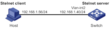
Configuration procedure
1. Configure the Stelnet server:
# Generate RSA key pairs.
<Switch> system-view
[Switch] public-key local create rsa
The range of public key modulus is (512 ~ 2048).
If the key modulus is greater than 512, it will take a few minutes.
Press CTRL+C to abort.
Input the modulus length [default = 1024]:
Generating Keys...
........................++++++
...................++++++
..++++++++
............++++++++
Create the key pair successfully.
# Generate a DSA key pair.
[Switch] public-key local create dsa
The range of public key modulus is (512 ~ 2048).
If the key modulus is greater than 512, it will take a few minutes.
Press CTRL+C to abort.
Input the modulus length [default = 1024]:
Generating Keys...
.++++++++++++++++++++++++++++++++++++++++++++++++++*
........+......+.....+......................................+
...+.................+..........+...+.
Create the key pair successfully.
# Generate an ECDSA key pair.
[Switch] public-key local create ecdsa secp256r1
Generating Keys...
.
Create the key pair successfully.
# Enable the Stelnet server.
[Switch] ssh server enable
# Assign an IP address to VLAN-interface 2. The Stelnet client uses this address as the destination for SSH connection.
[Switch] interface vlan-interface 2
[Switch-Vlan-interface2] ip address 192.168.1.40 255.255.255.0
[Switch-Vlan-interface2] quit
# Set the authentication mode to AAA for user lines.
[Switch] line vty 0 63
[Switch-line-vty0-63] authentication-mode scheme
[Switch-line-vty0-63] quit
# Create a local device management user named client001.
[Switch] local-user client001 class manage
# Set the password to aabbcc in plain text for local user client001.
[Switch-luser-manage-client001] password simple aabbcc
# Authorize local user client001 to use the SSH service.
[Switch-luser-manage-client001] service-type ssh
# Assign the network-admin user role to local user client001.
[Switch-luser-manage-client001] authorization-attribute user-role network-admin
[Switch-luser-manage-client001] quit
# Create an SSH user named client001. Specify the service type as stelnet and the authentication method as password for the user.
[Switch] ssh user client001 service-type stelnet authentication-type password
2. Establish a connection to the Stelnet server:
There are different types of Stelnet client software, such as PuTTY and OpenSSH. This example uses an Stelnet client that runs PuTTY version 0.58.
To establish a connection to the Stelnet server:
a. Launch PuTTY.exe to enter the interface shown in Figure 20.
b. In the Host Name (or IP address) field, enter the IP address 192.168.1.40 of the Stelnet server.
Figure 20 Specifying the host name (or IP address)

a. Click Open to connect to the server.
If the connection is successfully established, the system notifies you to enter the username and password. After entering the username (client001 in this example) and password (aabbcc in this example), you can enter the CLI of the server.
Publickey authentication enabled Stelnet server configuration example
Network requirements
As shown in Figure 21, the switch acts as the Stelnet server, and it uses publickey authentication and the RSA public key algorithm.
Establish an Stelnet connection between the host and the switch, so you can log in to the switch to configure and manage the switch.
Configuration procedure
In the server configuration, the client's host public key is required. Use the client software to generate RSA key pairs on the client before configuring the Stelnet server.
There are different types of Stelnet client software, such as PuTTY and OpenSSH. This example uses an Stelnet client that runs PuTTY version 0.58.
The configuration procedure is as follows:
1. Generate RSA key pairs on the Stelnet client:
a. Run PuTTYGen.exe on the client, select SSH-2 RSA and click Generate.
Figure 22 Generating a key pair on the client
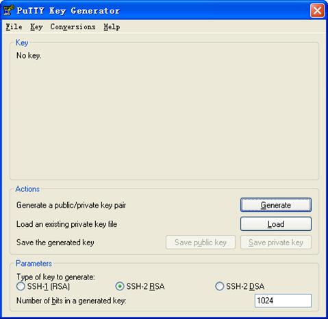
a. Continue moving the mouse during the key generating process, but do not place the mouse over the green progress bar shown in Figure 23. Otherwise, the progress bar stops moving and the key pair generating progress stops.
a. After the key pair is generated, click Save public key to save the public key.
A file saving window appears.
Figure 24 Saving a key pair on the client
a. Enter a file name (key.pub in this example), and click Save.
b. On the page shown in Figure 24, click Save private key to save the private key.
A confirmation dialog box appears.
c. Click Yes.
A file saving window appears.
d. Enter a file name (private.ppk in this example), and click Save.
e. Transmit the public key file to the server through FTP or TFTP. (Details not shown.)
2. Configure the Stelnet server:
# Generate RSA key pairs.
<Switch> system-view
[Switch] public-key local create rsa
The range of public key modulus is (512 ~ 2048).
If the key modulus is greater than 512, it will take a few minutes.
Press CTRL+C to abort.
Input the modulus length [default = 1024]:
Generating Keys...
........................++++++
...................++++++
..++++++++
............++++++++
Create the key pair successfully.
# Generate a DSA key pair.
[Switch] public-key local create dsa
The range of public key modulus is (512 ~ 2048).
If the key modulus is greater than 512, it will take a few minutes.
Press CTRL+C to abort.
Input the modulus length [default = 1024]:
Generating Keys...
.++++++++++++++++++++++++++++++++++++++++++++++++++*
........+......+.....+......................................+
...+.................+..........+...+
Create the key pair successfully.
# Generate an ECDSA key pair.
[Switch] public-key local create ecdsa secp256r1
Generating Keys...
.
Create the key pair successfully.
# Enable the Stelnet server.
[Switch] ssh server enable
# Assign an IP address to VLAN-interface 2. The Stelnet client uses this IP address as the destination for SSH connection.
[Switch] interface vlan-interface 2
[Switch-Vlan-interface2] ip address 192.168.1.40 255.255.255.0
[Switch-Vlan-interface2] quit
# Set the authentication mode to AAA for user lines.
[Switch] line vty 0 63
[Switch-line-vty0-63] authentication-mode scheme
[Switch-line-vty0-63] quit
# Import the client's public key from the public key file key.pub and name it switchkey.
[Switch] public-key peer switchkey import sshkey key.pub
# Create an SSH user named client002. Specify the authentication method as publickey for the user, and assign the public key switchkey to the user.
[Switch] ssh user client002 service-type stelnet authentication-type publickey assign publickey switchkey
# Create a local device management user named client002.
[Switch] local-user client002 class manage
# Authorize local user client002 to use the SSH service.
[Switch-luser-manage-client002] service-type ssh
# Assign the network-admin user role to local user client002.
[Switch-luser-manage-client002] authorization-attribute user-role network-admin
[Switch-luser-manage-client002] quit
3. Specify the private key file and establish a connection to the Stelnet server:
a. Launch PuTTY.exe on the Stelnet client to enter the interface shown in Figure 25.
b. In the Host Name (or IP address) field, enter the IP address of the Stelnet server 192.168.1.40.
Figure 25 Specifying the host name (or IP address)
a. Select Connection > SSH from the navigation tree.
The window shown in Figure 26 appears.
b. Specify the Preferred SSH protocol version as 2.
Figure 26 Specifying the preferred SSH version
a. Select Connection > SSH > Auth from the navigation tree.
The window shown in Figure 27 appears.
b. Click Browse… to bring up the file selection window, navigate to the private key file (private.ppk in this example), and click OK.
Figure 27 Specifying the private key file
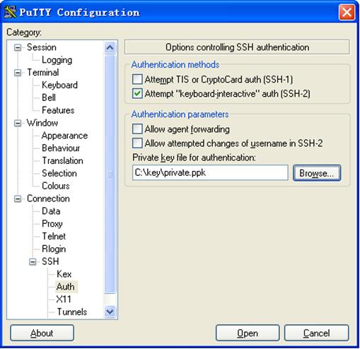
a. Click Open to connect to the server.
If the connection is successfully established, the system notifies you to enter the username. After entering the username (client002), you can enter the CLI of the server.
Password authentication enabled Stelnet client configuration example
Network requirements
As shown in Figure 28:
· Switch B acts as the Stelnet server and uses password authentication.
· The username and password of the client are saved on Switch B.
Establish an Stelnet connection between Switch A and Switch B, so you can log in to Switch B to configure and manage Switch B.
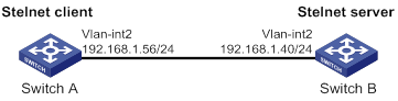
Configuration procedure
1. Configure the Stelnet server:
# Generate RSA key pairs.
<SwitchB> system-view
[SwitchB] public-key local create rsa
The range of public key modulus is (512 ~ 2048).
If the key modulus is greater than 512, it will take a few minutes.
Press CTRL+C to abort.
Input the modulus length [default = 1024]:
Generating Keys...
........................++++++
...................++++++
..++++++++
............++++++++
Create the key pair successfully.
# Generate a DSA key pair.
[SwitchB] public-key local create dsa
The range of public key modulus is (512 ~ 2048).
If the key modulus is greater than 512, it will take a few minutes.
Press CTRL+C to abort.
Input the modulus length [default = 1024]:
Generating Keys...
.++++++++++++++++++++++++++++++++++++++++++++++++++*
........+......+.....+......................................+
...+.................+..........+...+
Create the key pair successfully.
# Generate an ECDSA key pair.
[SwitchB] public-key local create ecdsa secp256r1
Generating Keys...
.
Create the key pair successfully.
# Enable the Stelnet server.
[SwitchB] ssh server enable
# Assign an IP address to VLAN-interface 2. The Stelnet client uses this address as the destination address of the SSH connection.
[SwitchB] interface vlan-interface 2
[SwitchB-Vlan-interface2] ip address 192.168.1.40 255.255.255.0
[SwitchB-Vlan-interface2] quit
# Set the authentication mode to AAA for user lines.
[SwitchB] line vty 0 63
[SwitchB-line-vty0-63] authentication-mode scheme
[SwitchB-line-vty0-63] quit
# Create a local device management user named client001.
[SwitchB] local-user client001 class manage
# Set the password to aabbcc in plain text for local user client001.
[SwitchB-luser-manage-client001] password simple aabbcc
# Authorize local user client001 to use the SSH service.
[SwitchB-luser-manage-client001] service-type ssh
# Assign the network-admin user role to local user client001.
[SwitchB-luser-manage-client001] authorization-attribute user-role network-admin
[SwitchB-luser-manage-client001] quit
# Create an SSH user named client001. Specify the service type as stelnet and the authentication method as password for the user.
[SwitchB] ssh user client001 service-type stelnet authentication-type password
2. Establish a connection to the Stelnet server:
# Assign an IP address to VLAN-interface 2.
<SwitchA> system-view
[SwitchA] interface vlan-interface 2
[SwitchA-Vlan-interface2] ip address 192.168.1.56 255.255.255.0
[SwitchA-Vlan-interface2] quit
[SwitchA] quit
Before establishing a connection to the server, you can configure the server's host public key on the client to authenticate the server.
? To configure the server's host public key on the client, perform the following tasks:
# Use the display public-key local dsa public command on the server to display the server's host public key. (Details not shown.)
# Enter public key view of the client and copy the host public key of the server to the client.
[SwitchA] public-key peer key1
Enter public key view. Return to system view with "peer-public-key end" command.
[SwitchA-pkey-public-key-key1]308201B73082012C06072A8648CE3804013082011F0281810
0D757262C4584C44C211F18BD96E5F0
[SwitchA-pkey-public-key-key1]61C4F0A423F7FE6B6B85B34CEF72CE14A0D3A5222FE08CECE
65BE6C265854889DC1EDBD13EC8B274
[SwitchA-pkey-public-key-key1]DA9F75BA26CCB987723602787E922BA84421F22C3C89CB9B0
6FD60FE01941DDD77FE6B12893DA76E
[SwitchA-pkey-public-key-key1]EBC1D128D97F0678D7722B5341C8506F358214B16A2FAC4B3
68950387811C7DA33021500C773218C
[SwitchA-pkey-public-key-key1]737EC8EE993B4F2DED30F48EDACE915F0281810082269009E
14EC474BAF2932E69D3B1F18517AD95
[SwitchA-pkey-public-key-key1]94184CCDFCEAE96EC4D5EF93133E84B47093C52B20CD35D02
492B3959EC6499625BC4FA5082E22C5
[SwitchA-pkey-public-key-key1]B374E16DD00132CE71B020217091AC717B612391C76C1FB2E
88317C1BD8171D41ECB83E210C03CC9
[SwitchA-pkey-public-key-key1]B32E810561C21621C73D6DAAC028F4B1585DA7F42519718CC
9B09EEF0381840002818000AF995917
[SwitchA-pkey-public-key-key1]E1E570A3F6B1C2411948B3B4FFA256699B3BF871221CC9C5D
F257523777D033BEE77FC378145F2AD
[SwitchA-pkey-public-key-key1]D716D7DB9FCABB4ADBF6FB4FDB0CA25C761B308EF53009F71
01F7C62621216D5A572C379A32AC290
[SwitchA-pkey-public-key-key1]E55B394A217DA38B65B77F0185C8DB8095522D1EF044B465E
8716261214A5A3B493E866991113B2D
[SwitchA-pkey-public-key-key1]485348
[SwitchA-pkey-public-key-key1] peer-public-key end
[SwitchA] quit
# Establish an SSH connection to the server, and specify the host public key of the server.
<SwitchA> ssh2 192.168.1.40 public-key key1
Username: client001
Press CTRL+C to abort.
Connecting to 192.168.1.40 port 22.
[email protected]'s password:
Enter a character ~ and a dot to abort.
******************************************************************************
* Copyright (c) 2004-2016 Hangzhou H3C Tech. Co., Ltd. All rights reserved. *
* Without the owner's prior written consent, *
* no decompiling or reverse-engineering shall be allowed. *
******************************************************************************
<SwitchB>
After you enter the correct password, you successfully log in to Switch B.
? If the client does not have the server's host public key, the system will notify you to confirm the further access when you access the server. Select Yes to access the server and download the server's host public key.
<SwitchA> ssh2 192.168.1.40
Username: client001
Press CTRL+C to abort.
Connecting to 192.168.1.40 port 22.
The server is not authenticated. Continue? [Y/N]:y
Do you want to save the server public key? [Y/N]:y
[email protected]'s password:
Enter a character ~ and a dot to abort.
******************************************************************************
* Copyright (c) 2004-2016 Hangzhou H3C Tech. Co., Ltd. All rights reserved. *
* Without the owner's prior written consent, *
* no decompiling or reverse-engineering shall be allowed. *
******************************************************************************
<SwitchB>
After you enter the correct password, you can access Switch B successfully. At the next connection attempt, the client authenticates the server by using the saved server's host public key on the client.
Publickey authentication enabled Stelnet client configuration example
Network requirements
As shown in Figure 29, Switch B acts as the Stelnet server, and it uses publickey authentication and the DSA public key algorithm.
Establish an Stelnet connection between Switch A and Switch B, so you can log in to Switch B to configure and manage Switch B.
Configuration procedure
In the server configuration, the client's host public key is required. Generate a DSA key pair on the client before configuring the Stelnet server.
1. Configure the Stelnet client:
# Assign an IP address to VLAN-interface 2.
<SwitchA> system-view
[SwitchA] interface vlan-interface 2
[SwitchA-Vlan-interface2] ip address 192.168.1.56 255.255.255.0
[SwitchA-Vlan-interface2] quit
# Generate a DSA key pair.
[SwitchA] public-key local create dsa
The range of public key modulus is (512 ~ 2048).
If the key modulus is greater than 512, it will take a few minutes.
Press CTRL+C to abort.
Input the modulus length [default = 1024]:
Generating Keys...
.++++++++++++++++++++++++++++++++++++++++++++++++++*
........+......+.....+......................................+
...+.................+..........+...+
Create the key pair successfully.
# Export the DSA host public key to a public key file named key.pub.
[SwitchA] public-key local export dsa ssh2 key.pub
[SwitchA] quit
# Transmit the public key file key.pub to the server through FTP or TFTP. (Details not shown.)
2. Configure the Stelnet server:
# Generate RSA key pairs.
<SwitchB> system-view
[SwitchB] public-key local create rsa
The range of public key modulus is (512 ~ 2048)
If the key modulus is greater than 512, it will take a few minutes.
Press CTRL+C to abort.
Input the modulus length [default = 1024]:
Generating Keys...
........................++++++
...................++++++
..++++++++
............++++++++
Create the key pair successfully.
# Generate a DSA key pair.
[SwitchB] public-key local create dsa
The range of public key modulus is (512 ~ 2048).
If the key modulus is greater than 512, it will take a few minutes.
Press CTRL+C to abort.
Input the modulus length [default = 1024]:
Generating Keys...
.++++++++++++++++++++++++++++++++++++++++++++++++++*
........+......+.....+......................................+
...+.................+..........+...+
Create the key pair successfully.
# Generate an ECDSA key pair.
[SwitchB] public-key local create ecdsa secp256r1
Generating Keys...
.
Create the key pair successfully.
# Enable the Stelnet server.
[SwitchB] ssh server enable
# Assign an IP address to VLAN-interface 2. The Stelnet client uses this address as the destination address for SSH connection.
[SwitchB] interface vlan-interface 2
[SwitchB-Vlan-interface2] ip address 192.168.1.40 255.255.255.0
[SwitchB-Vlan-interface2] quit
# Set the authentication mode to AAA for user lines.
[SwitchB] line vty 0 63
[SwitchB-line-vty0-63] authentication-mode scheme
[SwitchB-line-vty0-63] quit
# Import the peer public key from the public key file key.pub, and name it switchkey.
[SwitchB] public-key peer switchkey import sshkey key.pub
# Create an SSH user named client002. Specify the authentication method as publickey for the user. Assign the public key switchkey to the user.
[SwitchB] ssh user client002 service-type stelnet authentication-type publickey assign publickey switchkey
# Create a local device management user named client002.
[SwitchB] local-user client002 class manage
# Authorize local user client002 to use the SSH service.
[SwitchB-luser-manage-client002] service-type ssh
# Assign the network-admin user role to local user client002.
[SwitchB-luser-manage-client002] authorization-attribute user-role network-admin
[SwitchB-luser-manage-client002] quit
3. Establish an SSH connection to the Stelnet server.
<SwitchA> ssh2 192.168.1.40 identity-key dsa
Username: client002
Press CTRL+C to abort.
Connecting to 192.168.1.40 port 22.
The server is not authenticated. Continue? [Y/N]:y
Do you want to save the server public key? [Y/N]:n
Enter a character ~ and a dot to abort.
******************************************************************************
* Copyright (c) 2004-2016 Hangzhou H3C Tech. Co., Ltd. All rights reserved. *
* Without the owner's prior written consent, *
* no decompiling or reverse-engineering shall be allowed. *
******************************************************************************
<SwitchB>
Select Yes to access the server and download the server's host public key. At the next connection attempt, the client authenticates the server by using the saved server's host public key on the client.
SFTP configuration examples
Unless otherwise noted, devices in the configuration examples operate in non-FIPS mode.
When the device acts as an SFTP server operating in FIPS mode, only ECDSA and RSA key pairs are supported. Do not generate a DSA key pair on the SFTP server.
Password authentication enabled SFTP server configuration example
Network requirements
As shown in Figure 30:
· The switch acts as the SFTP server and uses password authentication.
· The username and password of the client are saved on the switch.
Establish an SFTP connection between the host and the switch, so you can log in to the switch to manage and transfer files.
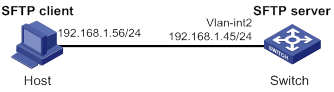
Configuration procedure
1. Configure the SFTP server:
# Generate RSA key pairs.
<Switch> system-view
[Switch] public-key local create rsa
The range of public key modulus is (512 ~ 2048).
If the key modulus is greater than 512, it will take a few minutes.
Press CTRL+C to abort.
Input the modulus length [default = 1024]:
Generating Keys...
........................++++++
...................++++++
..++++++++
............++++++++
Create the key pair successfully.
# Generate a DSA key pair.
[Switch] public-key local create dsa
The range of public key modulus is (512 ~ 2048).
If the key modulus is greater than 512, it will take a few minutes.
Press CTRL+C to abort.
Input the modulus length [default = 1024]:
Generating Keys...
.++++++++++++++++++++++++++++++++++++++++++++++++++*
........+......+.....+......................................+
...+.................+..........+...+
Create the key pair successfully.
# Generate an ECDSA key pair.
[Switch] public-key local create ecdsa secp256r1
Generating Keys...
.
Create the key pair successfully.
# Enable the SFTP server.
[Switch] sftp server enable
# Assign an IP address to VLAN-interface 2. The client uses this address as the destination for SSH connection.
[Switch] interface vlan-interface 2
[Switch-Vlan-interface2] ip address 192.168.1.45 255.255.255.0
[Switch-Vlan-interface2] quit
# Create a local device management user named client002.
[Switch] local-user client002 class manage
# Set the password to aabbcc in plain text for local user client002.
[Switch-luser-manage-client002] password simple aabbcc
# Authorize local user client002 to use the SSH service.
[Switch-luser-manage-client002] service-type ssh
# Assign the network-admin user role and working directory flash:/ to local user client002.
[Switch-luser-manage-client002] authorization-attribute user-role network-admin work-directory flash:/
[Switch-luser-manage-client002] quit
# Create an SSH user named client002. Specify the authentication method as password and service type as sftp for the user.
[Switch] ssh user client002 service-type sftp authentication-type password
2. Establish a connection between the SFTP client and the SFTP server:
The device supports different types of SFTP client software. This example uses an SFTP client that runs PSFTP of PuTTy version 0.58.
|
|
NOTE: PSFTP supports only password authentication. |
To establish a connection to the SFTP server:
a. Run the psftp.exe to launch the client interface shown in Figure 31, and enter the following command:
open 192.168.1.45
b. Enter username client002 and password aabbcc as prompted to log in to the SFTP server.
Figure 31 SFTP client interface
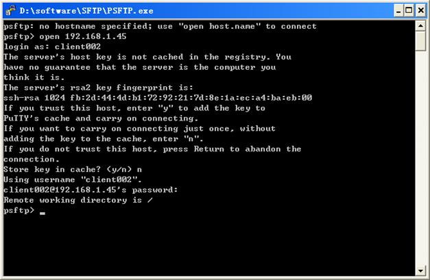
Publickey authentication enabled SFTP client configuration example
Network requirements
As shown in Figure 32, Switch B acts as the SFTP server, and it uses publickey authentication and the RSA public key algorithm.
Establish an SFTP connection between Switch A and Switch B, so you can log in to Switch B to manage and transfer files.
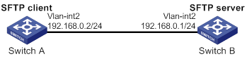
Configuration procedure
In the server configuration, the client's host public key is required. Generate RSA key pairs on the client before configuring the SFTP server.
1. Configure the SFTP client:
# Assign an IP address to VLAN-interface 2.
<SwitchA> system-view
[SwitchA] interface vlan-interface 2
[SwitchA-Vlan-interface2] ip address 192.168.0.2 255.255.255.0
[SwitchA-Vlan-interface2] quit
# Generate RSA key pairs.
[SwitchA] public-key local create rsa
The range of public key size is (512 ~ 2048).
If the key modulus is greater than 512, it will take a few minutes.
Press CTRL+C to abort.
Input the modulus length [default = 1024]:
Generating Keys...
........................++++++
...................++++++
..++++++++
............++++++++
Create the key pair successfully.
# Export the host public key to a public key file named pubkey.
[SwitchA] public-key local export rsa ssh2 pubkey
[SwitchA] quit
# Transmit the public key file pubkey to the server through FTP or TFTP. (Details not shown.)
2. Configure the SFTP server:
# Generate RSA key pairs.
<SwitchB> system-view
[SwitchB] public-key local create rsa
The range of public key size is (512 ~ 2048).
If the key modulus is greater than 512, it will take a few minutes.
Press CTRL+C to abort.
Input the modulus length [default = 1024]:
Generating Keys...
........................++++++
...................++++++
..++++++++
............++++++++
Create the key pair successfully.
# Generate a DSA key pair.
[SwitchB] public-key local create dsa
The range of public key size is (512 ~ 2048).
If the key modulus is greater than 512, it will take a few minutes.
Press CTRL+C to abort.
Input the modulus length [default = 1024]:
Generating Keys...
.++++++++++++++++++++++++++++++++++++++++++++++++++*
........+......+.....+......................................+
...+.................+..........+...+
Create the key pair successfully.
# Generate an ECDSA key pair.
[SwitchB] public-key local create ecdsa secp256r1
Generating Keys...
.
Create the key pair successfully.
# Enable the SFTP server.
[SwitchB] sftp server enable
# Assign an IP address to VLAN-interface 2. The SSH client uses this address as the destination for SSH connection.
[SwitchB] interface vlan-interface 2
[SwitchB-Vlan-interface2] ip address 192.168.0.1 255.255.255.0
[SwitchB-Vlan-interface2] quit
# Import the peer public key from the public key file pubkey, and name it switchkey.
[SwitchB] public-key peer switchkey import sshkey pubkey
# Create an SSH user named client001. Specify the service type as sftp and the authentication method as publickey for the user. Assign the public key switchkey to the user.
[SwitchB] ssh user client001 service-type sftp authentication-type publickey assign publickey switchkey
# Create a local device management user named client001.
[SwitchB] local-user client001 class manage
# Authorize local user client001 to use the SSH service.
[SwitchB-luser-manage-client001] service-type ssh
# Assign the network-admin user role and working directory flash:/ to local user client001.
[SwitchB-luser-manage-client001] authorization-attribute user-role network-admin work-directory flash:/
[SwitchB-luser-manage-client001] quit
3. Establish a connection to the SFTP server:
# Establish a connection to the SFTP server and enter SFTP client view.
<SwitchA> sftp 192.168.0.1 identity-key rsa
Username: client001
Press CTRL+C to abort.
Connecting to 192.168.0.1 port 22.
The server is not authenticated. Continue? [Y/N]:y
Do you want to save the server public key? [Y/N]:n
sftp>
# Display files under the current directory of the server, delete file z, and verify the result.
sftp> dir -l
-rwxrwxrwx 1 noone nogroup 1759 Aug 23 06:52 config.cfg
-rwxrwxrwx 1 noone nogroup 225 Aug 24 08:01 pubkey2
-rwxrwxrwx 1 noone nogroup 283 Aug 24 07:39 pubkey
drwxrwxrwx 1 noone nogroup 0 Sep 01 06:22 new
-rwxrwxrwx 1 noone nogroup 225 Sep 01 06:55 pub
-rwxrwxrwx 1 noone nogroup 0 Sep 01 08:00 z
sftp> delete z
Removing /z
sftp> dir -l
-rwxrwxrwx 1 noone nogroup 1759 Aug 23 06:52 config.cfg
-rwxrwxrwx 1 noone nogroup 225 Aug 24 08:01 pubkey2
-rwxrwxrwx 1 noone nogroup 283 Aug 24 07:39 pubkey
drwxrwxrwx 1 noone nogroup 0 Sep 01 06:22 new
-rwxrwxrwx 1 noone nogroup 225 Sep 01 06:55 pub
# Add a directory named new1 and verify the result.
sftp> mkdir new1
sftp> dir -l
-rwxrwxrwx 1 noone nogroup 1759 Aug 23 06:52 config.cfg
-rwxrwxrwx 1 noone nogroup 225 Aug 24 08:01 pubkey2
-rwxrwxrwx 1 noone nogroup 283 Aug 24 07:39 pubkey
drwxrwxrwx 1 noone nogroup 0 Sep 01 06:22 new
-rwxrwxrwx 1 noone nogroup 225 Sep 01 06:55 pub
drwxrwxrwx 1 noone nogroup 0 Sep 02 06:30 new1
# Change the name of directory new1 to new2 and verify the result.
sftp> rename new1 new2
sftp> dir -l
-rwxrwxrwx 1 noone nogroup 1759 Aug 23 06:52 config.cfg
-rwxrwxrwx 1 noone nogroup 225 Aug 24 08:01 pubkey2
-rwxrwxrwx 1 noone nogroup 283 Aug 24 07:39 pubkey
drwxrwxrwx 1 noone nogroup 0 Sep 01 06:22 new
-rwxrwxrwx 1 noone nogroup 225 Sep 01 06:55 pub
drwxrwxrwx 1 noone nogroup 0 Sep 02 06:33 new2
# Download file pubkey2 from the server and save it as a local file named public.
sftp> get pubkey2 public
Fetching / pubkey2 to public
/pubkey2 100% 225 1.4KB/s 00:00
# Upload the local file pu to the server, save it as puk, and verify the result.
sftp> put pu puk
Uploading pu to / puk
sftp> dir -l
-rwxrwxrwx 1 noone nogroup 1759 Aug 23 06:52 config.cfg
-rwxrwxrwx 1 noone nogroup 225 Aug 24 08:01 pubkey2
-rwxrwxrwx 1 noone nogroup 283 Aug 24 07:39 pubkey
drwxrwxrwx 1 noone nogroup 0 Sep 01 06:22 new
drwxrwxrwx 1 noone nogroup 0 Sep 02 06:33 new2
-rwxrwxrwx 1 noone nogroup 283 Sep 02 06:35 pub
-rwxrwxrwx 1 noone nogroup 283 Sep 02 06:36 puk
sftp>
# Exit SFTP client view.
sftp> quit
<SwitchA>
SCP configuration example with password authentication
Unless otherwise noted, devices in the configuration examples operate in non-FIPS mode.
When the device acts as an SCP server and is operating in FIPS mode, only ECDSA and RSA key pairs are supported. Do not generate a DSA key pair on the SCP server.
Network requirements
As shown in Figure 33:
· Switch B uses the password authentication method.
· The client 's username and password are saved on Switch B.
Establish an SCP connection between Switch A and Switch B, so you can log in to Switch B to transfer files.
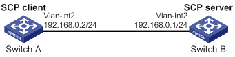
Configuration procedure
1. Configure the SCP server:
# Generate RSA key pairs.
<SwitchB> system-view
[SwitchB] public-key local create rsa
The range of public key modulus is (512 ~ 2048).
If the key modulus is greater than 512, it will take a few minutes.
Press CTRL+C to abort.
Input the modulus length [default = 1024]:
Generating Keys...
........................++++++
...................++++++
..++++++++
............++++++++
Create the key pair successfully.
# Generate a DSA key pair.
[SwitchB] public-key local create dsa
The range of public key modulus is (512 ~ 2048).
If the key modulus is greater than 512, it will take a few minutes.
Press CTRL+C to abort.
Input the modulus length [default = 1024]:
Generating Keys...
.++++++++++++++++++++++++++++++++++++++++++++++++++*
........+......+.....+......................................+
...+.................+..........+...+.
Create the key pair successfully.
# Generate an ECDSA key pair.
[SwitchB] public-key local create ecdsa secp256r1
Generating Keys...
.
Create the key pair successfully.
# Enable the SCP server.
[SwitchB] scp server enable
# Configure an IP address for VLAN-interface 2. The client uses this address as the destination for SCP connection.
[SwitchB] interface vlan-interface 2
[SwitchB-Vlan-interface2] ip address 192.168.0.1 255.255.255.0
[SwitchB-Vlan-interface2] quit
# Create a local device management user named client001.
[SwitchB] local-user client001 class manage
# Set the password to aabbcc in plain text for local user client001.
[SwitchB-luser-manage-client001] password simple aabbcc
# Authorize local user client001 to use the SSH service.
[SwitchB-luser-manage-client001] service-type ssh
# Assign the network-admin user role to local user client001.
[SwitchB-luser-manage-client001] authorization-attribute user-role network-admin
[SwitchB-luser-manage-client001] quit
# Create an SSH user named client001. Specify the service type as scp and the authentication method as password for the user.
[SwitchB] ssh user client001 service-type scp authentication-type password
2. Configure an IP address for VLAN-interface 2 on the SCP client.
<SwitchA> system-view
[SwitchA] interface vlan-interface 2
[SwitchA-Vlan-interface2] ip address 192.168.0.2 255.255.255.0
[SwitchA-Vlan-interface2] quit
[SwitchA] quit
3. Connect to the SCP server, download file remote.bin from the server, and save it as a local file named local.bin.
<SwitchA> scp 192.168.0.1 get remote.bin local.bin
Username: client001
Press CTRL+C to abort.
Connecting to 192.168.0.1 port 22.
The server is not authenticated. Continue? [Y/N]:y
Do you want to save the server public key? [Y/N]:n
[email protected]’s password:
remote.bin 100% 2875 2.8KB/s 00:00
NETCONF over SSH configuration example with password authentication
Unless otherwise noted, the device in the configuration example operates in non-FIPS mode.
When the device acts as a NETCONF-over-SSH server operating in FIPS mode, only ECDSA and RSA key pairs are supported. Do not generate a DSA key pair on the NETCONF-over-SSH server.
Network requirements
As shown in Figure 34:
· The switch uses local password authentication.
· The client's username and password are saved on the switch.
Establish a NETCONF-over-SSH connection between the host and the switch, so that you can log in to the switch to perform NETCONF operations.
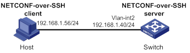
Configuration procedure
# Generate RSA key pairs.
<Switch> system-view
[Switch] public-key local create rsa
The range of public key modulus is (512 ~ 2048).
If the key modulus is greater than 512, it will take a few minutes.
Press CTRL+C to abort.
Input the modulus length [default = 1024]:
Generating Keys...
........................++++++
...................++++++
..++++++++
............++++++++
Create the key pair successfully.
# Generate a DSA key pair.
[Switch] public-key local create dsa
The range of public key modulus is (512 ~ 2048).
If the key modulus is greater than 512, it will take a few minutes.
Press CTRL+C to abort.
Input the modulus length [default = 1024]:
Generating Keys...
.++++++++++++++++++++++++++++++++++++++++++++++++++*
........+......+.....+......................................+
...+.................+..........+...+.
Create the key pair successfully.
# Generate an ECDSA key pair.
[Switch] public-key local create ecdsa secp256r1
Generating Keys...
.
Create the key pair successfully.
# Enable NETCONF over SSH.
[Switch] netconf ssh server enable
# Configure an IP address for VLAN-interface 2. The client uses this address as the destination for NETCONF-over-SSH connection.
[Switch] interface vlan-interface 2
[Switch-Vlan-interface2] ip address 192.168.1.40 255.255.255.0
[Switch-Vlan-interface2] quit
# Set the authentication mode to AAA for user lines.
[Switch] line vty 0 63
[Switch-line-vty0-63] authentication-mode scheme
[Switch-line-vty0-63] quit
# Create a local device management user named client001.
[Switch] local-user client001 class manage
# Set the password to aabbcc in plain text for local user client001.
[Switch-luser-manage-client001] password simple aabbcc
# Authorize local user client001 to use the SSH service.
[Switch-luser-manage-client001] service-type ssh
# Assign the network-admin user role to local user client001.
[Switch-luser-manage-client001] authorization-attribute user-role network-admin
[Switch-luser-manage-client001] quit
# Create an SSH user named client001. Specify the service type as NETCONF and the authentication method as password for the user.
[Switch] ssh user client001 service-type netconf authentication-type password
Verifying the configuration
# Verify that you can perform NETCONF operations after logging in to the switch. (Details not shown.)
Configuring attack detection and prevention
Overview
Attack detection and prevention enables a device to detect attacks by inspecting arriving packets, and to take prevention actions to protect a private network. Prevention actions include logging and packet dropping.
Attacks that the device can prevent
This section describes the attacks that the device can detect and prevent.
Single-packet attacks
Single-packet attacks are also known as malformed packet attacks. An attacker typically launches single-packet attacks by using the following methods:
· An attacker sends defective packets to a device, which causes the device to malfunction or crash.
· An attacker sends normal packets to a device, which interrupts connections or probes network topologies.
· An attacker sends a large number of forged packets to a target device, which consumes network bandwidth and causes denial of service (DoS).
Table 9 lists the single-packet attack types that the device can detect and prevent.
Table 9 Types of single-packet attacks
|
Single-packet attack |
Description |
|
ICMP redirect |
An attacker sends ICMP redirect messages to modify the victim's routing table. The victim cannot forward packets correctly. |
|
ICMP destination unreachable |
An attacker sends ICMP destination unreachable messages to cut off the connections between the victim and its destinations. |
|
ICMP type |
A receiver responds to an ICMP packet according to its type. An attacker sends forged ICMP packets of a specific type to affect the packet processing of the victim. |
|
ICMPv6 type |
A receiver responds to an ICMPv6 packet according to its type. An attacker sends forged ICMPv6 packets of specific types to affect the packet processing of the victim. |
|
Land |
An attacker sends the victim a large number of TCP SYN packets, which contain the victim's IP address as the source and destination IP addresses. This attack exhausts the half-open connection resources on the victim, and locks the victim's system. |
|
Large ICMP packet |
An attacker sends large ICMP packets to crash the victim. Large ICMP packets can cause memory allocation error and crash the protocol stack. |
|
Large ICMPv6 packet |
An attacker sends large ICMPv6 packets to crash the victim. Large ICMPv6 packets can cause memory allocation error and crash the protocol stack. |
|
IP options |
An attacker sends IP datagrams in which the IP options are abnormal. This attack intends to probe the network topology. The target system will break down if it is incapable of processing error packets. |
|
IP fragment |
An attacker sends the victim an IP datagram with an offset smaller than 5, which causes the victim to malfunction or crash. |
|
IP impossible packet |
An attacker sends IP packets in which source IP address is the same as the destination IP address, which causes the victim to malfunction. |
|
Tiny fragment |
An attacker makes the fragment size small enough to force Layer 4 header fields into the second fragment. These fragments can pass the packet filtering because they do not hit any match. |
|
Smurf |
An attacker broadcasts an ICMP echo request to target networks. These requests contain the victim's IP address as the source IP address. Every receiver on the target networks will send an ICMP echo reply to the victim. The victim will be flooded with replies, and will be unable to provide services. Network congestion might occur. |
|
TCP flag |
An attacker sends packets with defective TCP flags to probe the operating system of the target host. Different operating systems process unconventional TCP flags differently. The target system will break down if it processes this type of packets incorrectly. |
|
Traceroute |
An attacker uses traceroute tools to probe the topology of the victim network. |
|
WinNuke |
An attacker sends Out-Of-Band (OOB) data to the TCP port 139 (NetBIOS) on the victim that runs Windows system. The malicious packets contain an illegal Urgent Pointer, which causes the victim's operating system to crash. |
|
UDP bomb |
An attacker sends a malformed UDP packet. The length value in the IP header is larger than the IP header length plus the length value in the UDP header. When the target system processes the packet, a buffer overflow can occur, which causes a system crash. |
|
UDP Snork |
An attacker sends a UDP packet with destination port 135 (the Microsoft location service) and source port 135, 7, or 19. This attack causes an NT system to exhaust its CPU. |
|
UDP Fraggle |
An attacker sends a large number of chargen packets with source UDP port 7 and destination UDP port 19 to a network. These packets use the victim's IP address as the source IP address. Replies will flood the victim, resulting in DoS. |
|
Teardrop |
An attacker sends a stream of overlapping fragments. The victim will crash when it tries to reassemble the overlapping fragments. |
|
Ping of death |
An attacker sends the victim an ICMP echo request larger than 65535 bytes that violates the IP protocol. When the victim reassembles the packet, a buffer overflow can occur, which causes a system crash. |
Scanning attacks
Scanning is a preintrusion activity used to prepare for intrusion into a network. The scanning allows the attacker to find a way into the target network and to disguise the attacker's identity.
Attackers use scanning tools to probe a network, find vulnerable hosts, and discover services that are running on the hosts. Attackers can use the information to launch attacks.
The device can detect and prevent the IP sweep and port scan attacks. If an attacker performs port scanning from multiple hosts to the target host, distributed port scan attacks occur.
Flood attacks
An attacker launches a flood attack by sending a large number of forged requests to the victim in a short period of time. The victim is too busy responding to these forged requests to provide services for legal users, and a DoS attack occurs.
The device can detect and prevent the following types of flood attacks:
· SYN flood attack.
A SYN flood attacker exploits the TCP three-way handshake characteristics and makes the victim unresponsive to legal users. An attacker sends a large number of SYN packets with forged source addresses to a server. This causes the server to open a large number of half-open connections and respond to the requests. However, the server will never receive the expected ACK packets. The server is unable to accept new incoming connection requests because all of its resources are bound to half-open connections.
· ACK flood attack.
An ACK packet is a TCP packet only with the ACK flag set. Upon receiving an ACK packet from a client, the server must search half-open connections for a match.
An ACK flood attacker sends a large number of ACK packets to the server. This causes the server to be busy searching for half-open connections, and the server is unable to process packets for normal services.
· SYN-ACK flood attack.
Upon receiving a SYN-ACK packet, the server must search for the matching SYN packet it has sent. A SYN-ACK flood attacker sends a large number of SYN-ACK packets to the server. This causes the server to be busy searching for SYN packets, and the server is unable to process packets for normal services.
· FIN flood attack.
FIN packets are used to shut down TCP connections.
A FIN flood attacker sends a large number of forged FIN packets to a server. The victim might shut down correct connections, or be unable to provide services because it is busy searching for matching connections.
· RST flood attack.
RST packets are used to abort TCP connections when TCP connection errors occur.
An RST flood attacker sends a large number of forged RST packets to a server. The victim might shut down correct connections, or be unable to provide services because it is busy searching for matching connections.
· DNS flood attack.
The DNS server processes and replies all DNS queries that it receives.
A DNS flood attacker sends a large number of forged DNS queries. This attack consumes the bandwidth and resources of the DNS server, which prevents the server from processing and replying legal DNS queries.
· HTTP flood attack.
Upon receiving an HTTP GET request, the HTTP server performs complex operations, including character string searching, database traversal, data reassembly, and format switching. These operations consume a large amount of system resources.
An HTTP flood attacker sends a large number of HTTP GET requests that exceed the processing capacity of the HTTP server, which causes the server to crash.
· ICMP flood attack.
An ICMP flood attacker sends ICMP request packets, such as ping packets, to a host at a fast rate. Because the target host is busy replying to these requests, it is unable to provide services.
· ICMPv6 flood attack.
An ICMPv6 flood attacker sends ICMPv6 request packets, such as ping packets, to a host at a fast rate. Because the target host is busy replying to these requests, it is unable to provide services.
· UDP flood attack.
A UDP flood attacker sends UDP packets to a host at a fast rate. These packets consume a large amount of the target host's bandwidth, so the host cannot provide other services.
TCP fragment attack
An attacker launches TCP fragment attacks by sending attack TCP fragments defined in RFC 1858:
· First fragments in which the TCP header is smaller than 20 bytes.
· Non-first fragments with a fragment offset of 8 bytes (FO=1).
Typically, packet filter detects the source and destination IP addresses, source and destination ports, and transport layer protocol of the first fragment of a TCP packet. If the first fragment passes the detection, all subsequent fragments of the TCP packet are allowed to pass through.
Because the first fragment of attack TCP packets does not hit any match in the packet filter, the subsequent fragments can all pass through. After the receiving host reassembles the fragments, a TCP fragment attack occurs.
To prevent TCP fragment attacks, enable TCP fragment attack prevention to drop attack TCP fragments.
Login dictionary attack
The login dictionary attack is an automated process to attempt to log in by trying all possible passwords from a pre-arranged list of values (the dictionary). Multiple login attempts can occur in a short period of time.
You can configure the login delay feature to slow down the login dictionary attacks. This feature enables the device to delay accepting another login request after detecting a failed login attempt for a user.
Attack detection and prevention configuration task list
|
Tasks at a glance |
|
(Required.) Configuring an attack defense policy: · (Required.) Creating an attack defense policy · (Required.) Perform at least one of the following tasks to configure attack detection: ? Configuring a single-packet attack defense policy ? Configuring a scanning attack defense policy ? Configuring a flood attack defense policy · (Optional.) Configuring attack detection exemption |
|
(Required.) Applying an attack defense policy to the device |
|
(Optional.) Enabling log non-aggregation for single-packet attack events |
|
(Optional.) Configuring TCP fragment attack prevention |
|
(Optional.) Enabling the login delay |
Configuring an attack defense policy
Creating an attack defense policy
An attack defense policy can contain a set of attack detection and prevention configuration against multiple attacks.
To create an attack defense policy:
|
Step |
Command |
Remarks |
|
1. Enter system view. |
system-view |
N/A |
|
2. Create an attack defense policy and enter its view. |
attack-defense policy policy-name |
By default, no attack defense policy exists. |
Configuring a single-packet attack defense policy
Single-packet attack detection inspects packets destined for the device based on packet signatures. If an attack packet is detected, the device can take the following actions:
· Output logs (the default action).
· Drop attack packets.
You can also configure the device to not take any actions.
To configure a single-packet attack defense policy:
|
Step |
Command |
Remarks |
|
1. Enter system view. |
system-view |
N/A |
|
2. Enter attack defense policy view. |
attack-defense policy policy-name |
N/A |
|
3. Configure signature detection for single-packet attacks. |
· signature detect { fraggle | fragment | impossible | land | large-icmp | large-icmpv6 | smurf | snork | tcp-all-flags | tcp-fin-only | tcp-invalid-flags | tcp-null-flag | tcp-syn-fin | tiny-fragment | traceroute | udp-bomb | winnuke } [ action { { drop | logging } * | none } ] · signature detect { ip-option-abnormal | ping-of-death | teardrop } action { drop | logging } * · signature detect icmp-type { icmp-type-value | address-mask-reply | address-mask-request | destination-unreachable | echo-reply | echo-request | information-reply | information-request | parameter-problem | redirect | source-quench | time-exceeded | timestamp-reply | timestamp-request } [ action { { drop | logging } * | none } ] · signature detect icmpv6-type { icmpv6-type-value | destination-unreachable | echo-reply | echo-request | group-query | group-reduction | group-report | packet-too-big | parameter-problem | time-exceeded } [ action { { drop | logging } * | none } ] · signature detect ip-option { option-code | internet-timestamp | loose-source-routing | record-route | route-alert | security | stream-id | strict-source-routing } [ action { { drop | logging } * | none } ] · signature detect ipv6-ext-header ext-header-value [ action { { drop | logging } * | none } ] |
By default, signature detection is not configured for single-packet attacks. You can configure signature detection for multiple single-packet attacks. |
|
4. (Optional.) Set the maximum length of safe ICMP or ICMPv6 packets. |
signature { large-icmp | large-icmpv6 } max-length length |
By default, the maximum length of safe ICMP or ICMPv6 packets is 4000 bytes. A large ICMP or ICMPv6 attack occurs if an ICMP or ICMPv6 packet larger than the specified length is detected. |
|
5. (Optional.) Specify the actions against single-packet attacks of a specific level. |
signature level { high | info | low | medium } action { { drop | logging } * | none } |
The default action is logging for single-packet attacks of the informational and low levels. The default actions are logging and drop for single-packet attacks of the medium and high levels. |
|
6. (Optional.) Enable signature detection for single-packet attacks of a specific level. |
signature level { high | info | low | medium } detect |
By default, signature detection is disabled for all levels of single-packet attacks. |
Configuring a scanning attack defense policy
Scanning attack detection inspects the incoming packet rate of connections to the device. If a source initiates connections at a rate equal to or exceeding the pre-defined threshold, the device can take the following actions:
· Output logs.
· Drop subsequent packets from the IP address of the attacker.
To configure a scanning attack defense policy:
|
Step |
Command |
Remarks |
|
1. Enter system view. |
system-view |
N/A |
|
2. Enter attack defense policy view. |
attack-defense policy policy-name |
N/A |
|
3. Configure scanning attack detection. |
scan detect level { high | low | medium } action { drop | logging } * |
By default, scanning attack detection is not configured. |
Configuring a flood attack defense policy
Flood attack detection monitors the rate at which connections are initiated to the device.
With flood attack detection enabled, the device is in attack detection state. When the packet sending rate to an IP address reaches the threshold, the device enters prevention state and takes the specified actions. When the rate is below the silence threshold (three-fourths of the threshold), the device returns to the attack detection state.
If a device has multiple interface modules, the global trigger threshold you set takes effect on each interface module. The global trigger threshold of the device is the product of multiplying the value you set by the interface module quantity.
You can configure flood attack detection and prevention for a specific IP address. For non-specific IP addresses, the device uses the global attack prevention settings.
Configuring a SYN flood attack defense policy
|
Step |
Command |
Remarks |
|
1. Enter system view. |
system-view |
N/A |
|
2. Enter attack defense policy view. |
attack-defense policy policy-name |
N/A |
|
3. Enable global SYN flood attack detection. |
syn-flood detect non-specific |
By default, global SYN flood attack detection is disabled. |
|
4. Set the global trigger threshold for SYN flood attack prevention. |
syn-flood threshold threshold-value |
The default setting is 1000. |
|
5. Specify global actions against SYN flood attacks. |
syn-flood action { drop | logging } * |
By default, no global action is specified for SYN flood attacks. |
|
6. Configure IP address-specific SYN flood attack detection. |
syn-flood detect { ip ipv4-address | ipv6 ipv6-address } [ vpn-instance vpn-instance-name ] [ threshold threshold-value ] [ action { { drop | logging } * | none } ] |
By default, IP address-specific SYN flood attack detection is not configured. |
Configuring an ACK flood attack defense policy
|
Step |
Command |
Remarks |
|
1. Enter system view. |
system-view |
N/A |
|
2. Enter attack defense policy view. |
attack-defense policy policy-name |
N/A |
|
3. Enable global ACK flood attack detection. |
ack-flood detect non-specific |
By default, global ACK flood attack detection is disabled. |
|
4. Set the global trigger threshold for ACK flood attack prevention. |
ack-flood threshold threshold-value |
The default setting is 1000. |
|
5. Specify global actions against ACK flood attacks. |
ack-flood action { drop | logging } * |
By default, no global action is specified for ACK flood attacks. |
|
6. Configure IP address-specific ACK flood attack detection. |
ack-flood detect { ip ipv4-address | ipv6 ipv6-address } [ vpn-instance vpn-instance-name ] [ threshold threshold-value ] [ action { { drop | logging } * | none } ] |
By default, IP address-specific ACK flood attack detection is not configured. |
Configuring a SYN-ACK flood attack defense policy
|
Step |
Command |
Remarks |
|
1. Enter system view. |
system-view |
N/A |
|
2. Enter attack defense policy view. |
attack-defense policy policy-name |
N/A |
|
3. Enable global SYN-ACK flood attack detection. |
syn-ack-flood detect non-specific |
By default, global SYN-ACK flood attack detection is disabled. |
|
4. Set the global trigger threshold for SYN-ACK flood attack prevention. |
syn-ack-flood threshold threshold-value |
The default setting is 1000. |
|
5. Specify global actions against SYN-ACK flood attacks. |
syn-ack-flood action { drop | logging } * |
By default, no global action is specified for SYN-ACK flood attacks. |
|
6. Configure IP address-specific SYN-ACK flood attack detection. |
syn-ack-flood detect { ip ipv4-address | ipv6 ipv6-address } [ vpn-instance vpn-instance-name ] [ threshold threshold-value ] [ action { { drop | logging } * | none } ] |
By default, IP address-specific SYN-ACK flood attack detection is not configured. |
Configuring a FIN flood attack defense policy
|
Step |
Command |
Remarks |
|
1. Enter system view. |
system-view |
N/A |
|
2. Enter attack defense policy view. |
attack-defense policy policy-name |
N/A |
|
3. Enable global FIN flood attack detection. |
fin-flood detect non-specific |
By default, global FIN flood attack detection is disabled. |
|
4. Set the global trigger threshold for FIN flood attack prevention. |
fin-flood threshold threshold-value |
The default setting is 1000. |
|
5. Specify global actions against FIN flood attacks. |
fin-flood action { drop | logging } * |
By default, no global action is specified for FIN flood attacks. |
|
6. Configure IP address-specific FIN flood attack detection. |
fin-flood detect { ip ipv4-address | ipv6 ipv6-address } [ vpn-instance vpn-instance-name ] [ threshold threshold-value ] [ action { { drop | logging } * | none } ] |
By default, IP address-specific FIN flood attack detection is not configured. |
Configuring an RST flood attack defense policy
|
Step |
Command |
Remarks |
|
1. Enter system view. |
system-view |
N/A |
|
2. Enter attack defense policy view. |
attack-defense policy policy-name |
N/A |
|
3. Enable global RST flood attack detection. |
rst-flood detect non-specific |
By default, global RST flood attack detection is disabled. |
|
4. Set the global trigger threshold for RST flood attack prevention. |
rst-flood threshold threshold-value |
The default setting is 1000. |
|
5. Specify global actions against RST flood attacks. |
rst-flood action { drop | logging } * |
By default, no global action is specified for RST flood attacks. |
|
6. Configure IP address-specific RST flood attack detection. |
rst-flood detect { ip ipv4-address | ipv6 ipv6-address } [ vpn-instance vpn-instance-name ] [ threshold threshold-value ] [ action { { drop | logging } * | none } ] |
By default, IP address-specific RST flood attack detection is not configured. |
Configuring an ICMP flood attack defense policy
|
Step |
Command |
Remarks |
|
1. Enter system view. |
system-view |
N/A |
|
2. Enter attack defense policy view. |
attack-defense policy policy-name |
N/A |
|
3. Enable global ICMP flood attack detection. |
icmp-flood detect non-specific |
By default, global ICMP flood attack detection is disabled. |
|
4. Set the global trigger threshold for ICMP flood attack prevention. |
icmp-flood threshold threshold-value |
The default setting is 1000. |
|
5. Specify global actions against ICMP flood attacks. |
icmp-flood action { drop | logging } * |
By default, no global action is specified for ICMP flood attacks. |
|
6. Configure IP address-specific ICMP flood attack detection. |
icmp-flood detect ip ip-address [ vpn-instance vpn-instance-name ] [ threshold threshold-value ] [ action { { drop | logging } * | none } ] |
By default, IP address-specific ICMP flood attack detection is not configured. |
Configuring an ICMPv6 flood attack defense policy
|
Step |
Command |
Remarks |
|
1. Enter system view. |
system-view |
N/A |
|
2. Enter attack defense policy view. |
attack-defense policy policy-name |
N/A |
|
3. Enable global ICMPv6 flood attack detection. |
icmpv6-flood detect non-specific |
By default, global ICMPv6 flood attack detection is disabled. |
|
4. Set the global trigger threshold for ICMPv6 flood attack prevention. |
icmpv6-flood threshold threshold-value |
The default setting is 1000. |
|
5. Specify global actions against ICMPv6 flood attacks. |
icmpv6-flood action { drop | logging } * |
By default, no global action is specified for ICMPv6 flood attacks. |
|
6. Configure IP address-specific ICMPv6 flood attack detection. |
icmpv6-flood detect ipv6 ipv6-address [ vpn-instance vpn-instance-name ] [ threshold threshold-value ] [ action { { drop | logging } * | none } ] |
By default, IP address-specific ICMPv6 flood attack detection is not configured. |
Configuring a UDP flood attack defense policy
|
Step |
Command |
Remarks |
|
1. Enter system view. |
system-view |
N/A |
|
2. Enter attack defense policy view. |
attack-defense policy policy-name |
N/A |
|
3. Enable global UDP flood attack detection. |
udp-flood detect non-specific |
By default, global UDP flood attack detection is disabled. |
|
4. Set the global trigger threshold for UDP flood attack prevention. |
udp-flood threshold threshold-value |
The default setting is 1000. |
|
5. Specify global actions against UDP flood attacks. |
udp-flood action { drop | logging } * |
By default, no global action is specified for UDP flood attacks. |
|
6. Configure IP address-specific UDP flood attack detection. |
udp-flood detect { ip ipv4-address | ipv6 ipv6-address } [ vpn-instance vpn-instance-name ] [ threshold threshold-value ] [ action { { drop | logging } * | none } ] |
By default, IP address-specific UDP flood attack detection is not configured. |
Configuring a DNS flood attack defense policy
|
Step |
Command |
Remarks |
|
1. Enter system view. |
system-view |
N/A |
|
2. Enter attack defense policy view. |
attack-defense policy policy-name |
N/A |
|
3. Enable global DNS flood attack detection. |
dns-flood detect non-specific |
By default, global DNS flood attack detection is disabled. |
|
4. Set the global trigger threshold for DNS flood attack prevention. |
dns-flood threshold threshold-value |
The default setting is 1000. |
|
5. (Optional.) Specify the global ports to be protected against DNS flood attacks. |
dns-flood port port-list |
By default, DNS flood attack prevention protects port 53. |
|
6. Specify global actions against DNS flood attacks. |
dns-flood action { drop | logging } * |
By default, no global action is specified for DNS flood attacks. |
|
7. Configure IP address-specific DNS flood attack detection. |
dns-flood detect { ip ipv4-address | ipv6 ipv6-address } [ vpn-instance vpn-instance-name ] [ port port-list ] [ threshold threshold-value ] [ action { { drop | logging } * | none } ] |
By default, IP address-specific DNS flood attack detection is not configured. |
Configuring an HTTP flood attack defense policy
|
Step |
Command |
Remarks |
|
1. Enter system view. |
system-view |
N/A |
|
2. Enter attack defense policy view. |
attack-defense policy policy-name |
N/A |
|
3. Enable global HTTP flood attack detection. |
http-flood detect non-specific |
By default, global HTTP flood attack detection is disabled. |
|
4. Set the global trigger threshold for HTTP flood attack prevention. |
http-flood threshold threshold-value |
The default setting is 1000. |
|
5. (Optional.) Specify the global ports to be protected against HTTP flood attacks. |
http-flood port port-list |
By default, HTTP flood attack prevention protects port 80. |
|
6. Specify global actions against HTTP flood attacks. |
http-flood action { drop | logging } * |
By default, no global action is specified for HTTP flood attacks. |
|
7. Configure IP address-specific HTTP flood attack detection. |
http-flood detect { ip ipv4-address | ipv6 ipv6-address } [ vpn-instance vpn-instance-name ] [ port port-list ] [ threshold threshold-value ] [ action { { drop | logging } * | none } ] |
By default, IP address-specific HTTP flood attack detection is not configured. |
Configuring attack detection exemption
The attack defense policy uses the ACL to identify exempted packets. The policy does not check the packets permitted by the ACL. You can configure the ACL to identify packets from trusted servers. The exemption feature reduces the false alarm rate and improves packet processing efficiency. For example, the attack defense policy identifies multicast packets with the same source addresses and different destination addresses as scanning attack packets (for example, OSPF or PIM packets). You can configure an ACL to exempt such packets from attack detection.
If an ACL is used for attack detection exemption, only the following match criteria in the ACL permit rules take effect:
· Source IP address.
· Destination IP address.
· Source port.
· Destination port.
· Protocol.
· L3VPN instance.
· The fragment keyword for matching non-first fragments.
To configure attack detection exemption:
|
Step |
Command |
Remarks |
|
1. Enter system view. |
system-view |
N/A |
|
2. Enter attack defense policy view. |
attack-defense policy policy-name |
N/A |
|
3. Configure attack detection exemption. |
exempt acl [ ipv6 ] { acl-number | name acl-name } |
By default, attack detection exemption is not configured. |
Applying an attack defense policy to the device
An attack defense policy applied to the device itself detects packets destined for the device and prevents attacks targeted at the device.
A switch uses hardware to implement packet forwarding and uses software to process packets if the packets are destined for the switch. The software does not provide any attack defense features, so you must apply an attack defense policy to the switch to prevent attacks aimed at the switch.
To apply an attack defense policy to the device:
|
Step |
Command |
Remarks |
|
1. Enter system view. |
system-view |
N/A |
|
2. Apply an attack defense policy to the device. |
attack-defense local apply policy policy-name |
By default, no attack defense policy is applied to the device. |
Enabling log non-aggregation for single-packet attack events
Log aggregation aggregates multiple logs generated during a period of time and sends one log. Logs that are aggregated must have the following attributes in common:
· Attacks are destined for the device.
· Attack type.
· Attack prevention action.
· Source and destination IP addresses.
· VPN instance to which the victim IP address belongs.
As a best practice, do not disable log aggregation. A large number of logs will consume the display resources of the console.
To enable log non-aggregation for single-packet attack events:
|
Step |
Command |
Remarks |
|
1. Enter system view. |
system-view |
N/A |
|
2. Enable log non-aggregation for single-packet attack events. |
attack-defense signature log non-aggregate |
By default, log non-aggregation is disabled for single-packet attack events. |
Configuring TCP fragment attack prevention
The TCP fragment attack prevention feature detects the length and fragment offset of received TCP fragments and drops attack TCP fragments.
TCP fragment attack prevention takes precedence over single-packet attack prevention. When both are used, incoming TCP packets are processed first by TCP fragment attack prevention and then by the single-packet attack defense policy.
To configure TCP fragment attack prevention:
|
Step |
Command |
Remarks |
|
1. Enter system view. |
system-view |
N/A |
|
2. Enable TCP fragment attack prevention. |
attack-defense tcp fragment enable |
By default, TCP fragment attack prevention is enabled. |
Enabling the login delay
The login delay feature delays the device from accepting a login request from a user after the user fails a login attempt. This feature can slow down login dictionary attacks.
To enable the login delay:
|
Step |
Command |
Remarks |
|
1. Enter system view. |
system-view |
N/A |
|
2. Enable the login delay feature. |
attack-defense login reauthentication-delay seconds |
By default, the login delay feature is disabled. The device does not delay accepting a login request from a user that has failed a login attempt. |
Displaying and maintaining attack detection and prevention
Use the display commands in any view and the reset commands in user view.
To display and maintain attack detection and prevention:
|
Task |
Command |
|
(In standalone mode.) Display attack detection and prevention statistics for the device. |
display attack-defense statistics local [ slot slot-number ] |
|
(In IRF mode.) Display attack detection and prevention statistics for the device. |
display attack-defense statistics local [ chassis chassis-number slot slot-number ] |
|
Display attack defense policy configuration. |
display attack-defense policy [ policy-name ] |
|
(In standalone mode.) Display information about IPv4 scanning attackers. |
display attack-defense scan attacker ip [ local [ slot slot-number ] ] [ count ] |
|
(In IRF mode.) Display information about IPv4 scanning attackers. |
display attack-defense scan attacker ip [ local [ chassis chassis-number slot slot-number ] ] [ count ] |
|
(In standalone mode.) Display information about IPv6 scanning attackers. |
display attack-defense scan attacker ipv6 [ local [ slot slot-number ] ] [ count ] |
|
(In IRF mode.) Display information about IPv6 scanning attackers. |
display attack-defense scan attacker ipv6 [ local [ chassis chassis-number slot slot-number ] ] [ count ] |
|
(In standalone mode.) Display information about IPv4 scanning attack victims. |
display attack-defense scan victim ip [ local [ slot slot-number ] ] [ count ] |
|
(In IRF mode.) Display information about IPv4 scanning attack victims. |
display attack-defense scan victim ip [ local [ chassis chassis-number slot slot-number ] ] [ count ] |
|
(In standalone mode.) Display information about IPv6 scanning attack victims. |
display attack-defense scan victim ipv6 [ local [ slot slot-number ] ] [ count ] |
|
(In IRF mode.) Display information about IPv6 scanning attack victims. |
display attack-defense scan victim ipv6 [ local [ chassis chassis-number slot slot-number ] ] [ count ] |
|
(In standalone mode.) Display flood attack detection and prevention statistics for an IPv4 address. |
display attack-defense { ack-flood | dns-flood | fin-flood | flood | http-flood | icmp-flood | rst-flood | syn-ack-flood | syn-flood | udp-flood } statistics ip [ ip-address [ vpn vpn-instance-name ] ] [ local [ slot slot-number ] ] [ count ] |
|
(In IRF mode.) Display flood attack detection and prevention statistics for an IPv4 address. |
display attack-defense { ack-flood | dns-flood | fin-flood | flood | http-flood | icmp-flood | rst-flood | syn-ack-flood | syn-flood | udp-flood } statistics ip [ ip-address [ vpn vpn-instance-name ] ] [ local [ chassis chassis-number slot slot-number ] ] [ count ] |
|
(In standalone mode.) Display flood attack detection and prevention statistics for an IPv6 address. |
display attack-defense { ack-flood | dns-flood | fin-flood | flood | http-flood | icmpv6-flood | rst-flood | syn-ack-flood | syn-flood | udp-flood } statistics ipv6 [ ipv6-address [ vpn vpn-instance-name ] ] [ local [ slot slot-number ] ] [ count ] |
|
(In IRF mode.) Display flood attack detection and prevention statistics for an IPv6 address. |
display attack-defense { ack-flood | dns-flood | fin-flood | flood | http-flood | icmpv6-flood | rst-flood | syn-ack-flood | syn-flood | udp-flood } statistics ipv6 [ ipv6-address [ vpn vpn-instance-name ] ] [ local [ chassis chassis-number slot slot-number ] ] [ count ] |
|
(In standalone mode.) Display information about IPv4 addresses protected by flood attack detection and prevention. |
display attack-defense policy policy-name { ack-flood | dns-flood | fin-flood | flood | http-flood | icmp-flood | rst-flood | syn-ack-flood | syn-flood | udp-flood } ip [ ip-address [ vpn vpn-instance-name ] ] [ slot slot-number ] [ count ] |
|
(In IRF mode.) Display information about IPv4 addresses protected by flood attack detection and prevention. |
display attack-defense policy policy-name { ack-flood | dns-flood | fin-flood | flood | http-flood | icmp-flood | rst-flood | syn-ack-flood | syn-flood | udp-flood } ip [ ip-address [ vpn vpn-instance-name ] ] [ chassis chassis-number slot slot-number ] [ count ] |
|
(In standalone mode.) Display information about IPv6 addresses protected by flood attack detection and prevention. |
display attack-defense policy policy-name { ack-flood | dns-flood | fin-flood | flood | http-flood | icmpv6-flood | rst-flood | syn-ack-flood | syn-flood | udp-flood } ipv6 [ ipv6-address [ vpn vpn-instance-name ] ] [ slot slot-number ] [ count ] |
|
(In IRF mode.) Display information about IPv6 addresses protected by flood attack detection and prevention. |
display attack-defense policy policy-name { ack-flood | dns-flood | fin-flood | flood | http-flood | icmpv6-flood | rst-flood | syn-ack-flood | syn-flood | udp-flood } ipv6 [ ipv6-address [ vpn vpn-instance-name ] ] [ chassis chassis-number slot slot-number ] [ count ] |
|
Clear attack detection and prevention statistics for the device. |
reset attack-defense statistics local |
|
Clear flood attack detection and prevention statistics. |
reset attack-defense policy policy-name flood protected { ip | ipv6 } statistics |
Attack detection and prevention configuration examples
Attack defense policy device application configuration example
Network requirements
Configure attack detection and prevention on the switch (the gateway) to protect against network attacks from the user side or the network side.
· To prevent TCP flag attacks and low level scanning attacks that aim at the switch, enable TCP flag attack prevention and scanning attack prevention. Configure the device to output logs if it detects such attacks.
· To prevent the SYN flood attacks that aim at the external interface of the switch, enable IP address-specific SYN flood attack detection for 192.168.2.1/24. When the device receives 5000 or more SYN packets sent to the protected IP address per second, it outputs logs and drops the packets.
· To prevent the SYN flood attacks that aim at the internal interface of the switch, enable global SYN flood attack detection. When the device receives 2000 or more SYN packets that are destined to the switch but not to the protected IP address per second, it outputs logs.
Figure 35 Network diagram
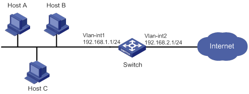
Configuration procedure
# Create an attack defense policy named a1.
[Switch] attack-defense policy a1
# Enable signature detection for TCP single packet attacks and specify logging as the attack prevention action. A TCP packet is identified as an attack packet if it has all flags set, only FIN flag set, invalid flags, no TCP flags set, or both SYN and FIN flags set.
[Switch-attack-defense-policy-a1] signature detect tcp-all-flags action logging
[Switch-attack-defense-policy-a1] signature detect tcp-fin-only action logging
[Switch-attack-defense-policy-a1] signature detect tcp-invalid-flags action logging
[Switch-attack-defense-policy-a1] signature detect tcp-null-flag action logging
[Switch-attack-defense-policy-a1] signature detect tcp-syn-fin action logging
# Enable low level scanning attack detection and specify logging as the attack prevention action.
[Router-attack-defense-policy-a1] scan detect level low action logging
# Enable SYN flood attack detection for 192.168.2.1. Set the threshold for triggering SYN flood attack prevention to 5000 and specify logging and drop as the attack prevention actions.
[Switch-attack-defense-policy-a1] syn-flood detect ip 192.168.2.1 threshold 5000 action logging drop
# Enable global SYN flood attack detection, set the global threshold for triggering SYN flood attack prevention to 2000, and specify logging as the global attack prevention action.
[Switch-attack-defense-policy-a1] syn-flood detect non-specific
[Switch-attack-defense-policy-a1] syn-flood threshold 2000
[Switch-attack-defense-policy-a1] syn-flood action logging
[Switch-attack-defense-policy-a1] quit
# Apply the attack defense policy to the device.
[Switch] attack-defense local apply policy a1
Verifying the configuration
# Verify that attack defense policy a1 is correctly configured.
[Switch] display attack-defense policy a1
Attack-defense Policy Information
--------------------------------------------------------------------------
Policy name : a1
Applied list : Local
--------------------------------------------------------------------------
Exempt IPv4 ACL : Not configured
Exempt IPv6 ACL : Not configured
--------------------------------------------------------------------------
Actions: CV-Client verify BS-Block source L-Logging D-Drop N-None
Signature attack defense configuration:
Signature name Defense Level Actions
Fragment Disabled low L
Impossible Disabled medium L,D
Teardrop Disabled medium L,D
Tiny fragment Disabled low L
IP option abnormal Disabled medium L,D
Smurf Enabled medium L,D
Traceroute Disabled low L
Ping of death Disabled medium L,D
Large ICMP Disabled info L
Max length 4000 bytes
Large ICMPv6 Disabled info L
Max length 4000 bytes
TCP invalid flags Disabled medium L
TCP null flag Disabled medium L
TCP all flags Disabled medium L
TCP SYN-FIN flags Disabled medium L
TCP FIN only flag Disabled medium L
TCP Land Disabled medium L,D
Winnuke Disabled medium L,D
UDP Bomb Disabled medium L,D
UDP Snork Disabled medium L,D
UDP Fraggle Disabled medium L,D
IP option record route Disabled info L
IP option internet timestamp Disabled info L
IP option security Disabled info L
IP option loose source routing Disabled info L
IP option stream ID Disabled info L
IP option strict source routing Disabled info L
IP option route alert Disabled info L
ICMP echo request Disabled info L
ICMP echo reply Disabled info L
ICMP source quench Disabled info L
ICMP destination unreachable Disabled info L
ICMP redirect Disabled info L
ICMP time exceeded Disabled info L
ICMP parameter problem Disabled info L
ICMP timestamp request Disabled info L
ICMP timestamp reply Disabled info L
ICMP information request Disabled info L
ICMP information reply Disabled info L
ICMP address mask request Disabled info L
ICMP address mask reply Disabled info L
ICMPv6 echo request Disabled info L
ICMPv6 echo reply Disabled info L
ICMPv6 group membership query Disabled info L
ICMPv6 group membership report Disabled info L
ICMPv6 group membership reduction Disabled info L
ICMPv6 destination unreachable Disabled info L
ICMPv6 time exceeded Disabled info L
ICMPv6 parameter problem Disabled info L
ICMPv6 packet too big Disabled info L
Scan attack defense configuration:
Defense : Enabled
Level : low
Actions : L
Flood attack defense configuration:
Flood type Global thres(pps) Global actions Service ports Non-specific
SYN flood 2000 L - Enabled
ACK flood 1000(default) - - Disabled
SYN-ACK flood 1000(default) - - Disabled
RST flood 1000(default) - - Disabled
FIN flood 1000(default) - - Disabled
UDP flood 1000(default) - - Disabled
ICMP flood 1000(default) - - Disabled
ICMPv6 flood 1000(default) - - Disabled
DNS flood 1000(default) - 53 Disabled
HTTP flood 1000(default) - 80 Disabled
Flood attack defense for protected IP addresses:
Address VPN instance Flood type Thres(pps) Actions Ports
192.168.2.1 -- SYN-FLOOD 5000 L,D -
If the device receives TCP flag attack packets or scanning attack packets that are destined for the device, the device outputs logs. If the device receives TCP SYN flood attack packets that are destined for the protected IP address, the device outputs logs and drops the attack packets. If the device receives TCP SYN flood attack packets that are destined for the device but not to the protected IP address, the device outputs logs.
# Display the attack detection and prevention statistics.
[Switch] display attack-defense statistics local
Attack policy name: a1
Slot 1:
Scan attack defense statistics:
AttackType AttackTimes Dropped
Port scan 4 0
Flood attack defense statistics:
AttackType AttackTimes Dropped
No flood attacks detected.
Signature attack defense statistics:
AttackType AttackTimes Dropped
TCP invalid flags 116 0
TCP null flag 709 0
TCP all flags 251 0
TCP SYN-FIN flags 46 0
TCP FIN only flag 130 0
Configuring TCP attack prevention
Overview
TCP attack prevention can detect and prevent attacks that exploit the TCP connection establishment process.
Configuring Naptha attack prevention
Naptha is a DDoS attack that targets operating systems. It exploits the resources consuming vulnerability in TCP/IP stack and network application process. The attacker establishes a large number of TCP connections in a short period of time and leaves them in certain states without requesting any data. These TCP connections starve the victim of system resources, resulting in a system breakdown.
After you enable Naptha attack prevention, the device periodically checks the number of TCP connections in each state (CLOSING, ESTABLISHED, FIN_WAIT_1, FIN_WAIT_2, and LAST_ACK). If the number of TCP connections in a state exceeds the limit, the device will accelerate the aging of the TCP connections in that state to mitigate the Naptha attack.
To configure Naptha attack prevention:
|
Step |
Command |
Remarks |
|
1. Enter system view. |
system-view |
N/A |
|
2. Enable Naptha attack prevention. |
tcp anti-naptha enable |
By default, Naptha attack prevention is disabled. |
|
3. (Optional.) Set the maximum number of TCP connections in a state. |
tcp state { closing | established | fin-wait-1 | fin-wait-2 | last-ack } connection-limit number |
By default, the maximum number of TCP connections in each state (CLOSING, ESTABLISHED, FIN_WAIT_1, FIN_WAIT_2, and LAST_ACK) is 50. To disable the device from accelerating the aging of the TCP connections in a state, set the value to 0. |
|
4. (Optional.) Set the interval for checking the number of TCP connections in each state. |
tcp check-state interval interval |
By default, the interval for checking the number of TCP connections in each state is 30 seconds. |
Configuring IP source guard
Overview
IP source guard (IPSG) prevents spoofing attacks by using an IPSG binding table to match legitimate packets. It drops packets that do not match the table. IPSG is a per-interface packet filter. Configuring the feature on one interface does not affect packet forwarding on another interface.
The IPSG binding table can include global and interface-specific bindings. IPSG first uses the interface-specific bindings to match packets. If no match is found, IPSG uses the global bindings. The IPSG bindings fall into the following types:
· IP.
· MAC.
· IP-MAC.
· IP-VLAN.
· MAC-VLAN.
· IP-MAC-VLAN.
IPSG bindings can be static or dynamic.
· Static bindings—Configured manually. Global IPSG supports only static IP-MAC bindings. For more information about global static IPSG bindings, see "Static IPSG bindings."
· Dynamic bindings—Generated based on information from other modules. For more information about dynamic bindings, see "Dynamic IPSG bindings."
As shown in Figure 36, IPSG forwards only the packets that match an IPSG binding.
Figure 36 IPSG application
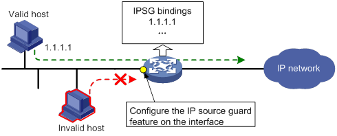
Static IPSG bindings
Static IPSG bindings are configured manually. They are suitable for scenarios where few hosts exist on a LAN and their IP addresses are manually configured. For example, you can configure a static IPSG binding on an interface that connects to a server. This binding allows the interface to receive packets only from the server.
Static IPSG bindings on an interface implements the following functions:
· Filter incoming IPv4 or IPv6 packets on the interface.
· Cooperate with ARP attack detection in IPv4 for user validity checking.
For information about ARP attack detection, see "Configuring ARP attack protection."
Static IPSG bindings can be global or interface-specific.
· Global static binding—Binds the IP address and MAC address in system view. The binding takes effect on all interfaces to filter packets for user spoofing attack prevention.
· Interface-specific static binding—Binds the IP address, MAC address, VLAN, or any combination of the items in interface view. The binding takes effect only on the interface to check the validity of users that are attempting to access the interface.
Dynamic IPSG bindings
IPSG automatically obtains user information from other modules to generate dynamic bindings. The source modules include DHCP snooping, DHCP relay agent, DHCPv6 relay agent, and DHCP server.
For example, DHCP-based IPSG bindings are suitable for scenarios where hosts on a LAN obtain IP addresses through DHCP. IPSG is configured on the DHCP server, the DHCP snooping device, or the DHCP relay agent. It generates dynamic bindings based on the client bindings on the DHCP server, the DHCP snooping entries, or the DHCP relay entries. IPSG allows only packets from the DHCP clients to pass through.
Dynamic IPv4SG
Dynamic bindings generated based on different source modules are for different usages:
|
Interface types |
Source modules |
Binding usage |
|
Layer 2 Ethernet port |
DHCP snooping |
Packet filtering. |
|
Layer 3 Ethernet interface/VLAN interface |
DHCP relay agent |
Packet filtering. |
|
DHCP server |
For cooperation with modules (such as the ARP attack detection module) to provide security services. |
For information about DHCP snooping, DHCP relay, and DHCP server, see Layer 3—IP Services Configuration Guide.
Dynamic IPv6SG
On a Layer 3 Ethernet interface or VLAN interface, IPv6SG can cooperate with DHCPv6 relay agent to generate IPv6SG bindings. Dynamic IPv6SG bindings generated based on DHCPv6 relay agent are for packet filtering.
For more information about DHCPv6 relay agent, see Layer 3—IP Services Configuration Guide.
IPSG configuration task list
To configure IPv4SG, perform the following tasks:
|
Tasks at a glance |
|
(Required.) Enabling IPv4SG on an interface |
|
(Optional.) Configuring a static IPv4SG binding |
To configure IPv6SG, perform the following tasks:
|
Tasks at a glance |
|
(Required.) Enabling IPv6SG on an interface |
|
(Optional.) Configuring a static IPv6SG binding |
Configuring the IPv4SG feature
You cannot configure the IPv4SG feature on a service loopback interface. If IPv4SG is enabled on an interface, you cannot assign the interface to a service loopback group.
Enabling IPv4SG on an interface
When you enable IPSG on an interface, the static and dynamic IPSG are both enabled.
· Static IPv4SG uses static bindings configured by using the ip source binding command.
· Dynamic IPv4SG generates dynamic bindings from related source modules. IPv4SG uses the bindings to filter incoming IPv4 packets based on the matching criteria specified in the ip verify source command.
To implement dynamic IPv4SG, make sure DHCP snooping, DHCP relay agent, or DHCP server operates correctly on the network.
To enable the IPv4SG feature on an interface:
|
Step |
Command |
Remarks |
|
1. Enter system view. |
system-view |
N/A |
|
2. Enter interface view. |
interface interface-type interface-number |
The following interface types are supported: · Layer 2 Ethernet port. · Layer 3 Ethernet interface. · Layer 3 Ethernet subinterface. · VLAN interface. |
|
3. Enable the IPv4SG feature. |
ip verify source { ip-address | ip-address mac-address | mac-address } |
By default, the IPv4SG feature is disabled on an interface. If you configure this command on an interface multiple times, the most recent configuration takes effect. |
Configuring a static IPv4SG binding
You can configure global static and interface-specific static IPv4SG bindings.
Global static bindings take effect on all interfaces.
Interface-specific static bindings take priority over global static bindings. An interface first uses the static bindings on the interface to match packets. If no match is found, the interface uses the global bindings.
Configuring a global static IPv4SG binding
|
Step |
Command |
Remarks |
|
1. Enter system view. |
system-view |
N/A |
|
2. Configure a global static IPv4SG binding. |
ip source binding ip-address ip-address mac-address mac-address |
No global static IPv4SG bindings exist. |
Configuring a static IPv4SG binding on an interface
|
Step |
Command |
Remarks |
|
1. Enter system view. |
system-view |
N/A |
|
2. Enter interface view. |
interface interface-type interface-number |
The following interface types are supported: · Layer 2 Ethernet port. · Layer 3 Ethernet interface. · Layer 3 Ethernet subinterface. · VLAN interface. |
|
3. Configure a static IPv4SG binding. |
ip source binding { ip-address ip-address | ip-address ip-address mac-address mac-address | mac-address mac-address } [ vlan vlan-id ] |
By default, no static IPv4SG bindings exist on an interface. The vlan vlan-id option is supported only in Layer 2 Ethernet interface view. To configure a static IPv4SG binding for the ARP attack detection feature, the vlan vlan-id option must be specified, and ARP attack detection must be enabled for the specified VLAN. You can configure the same static IPv4SG binding on different interfaces. |
Configuring the IPv6SG feature
You cannot configure the IPv6SG feature on a service loopback interface. If IPv6SG is enabled on an interface, you cannot assign the interface to a service loopback group.
Enabling IPv6SG on an interface
When you enable IPv6SG on an interface, the static and dynamic IPv6SG are both enabled.
· Static IPv6SG uses static bindings configured by using the ipv6 source binding command.
· Dynamic IPv6SG generates dynamic bindings from related source modules. IPv6SG uses the bindings to filter incoming IPv6 packets based on the matching criteria specified in the ipv6 verify source command.
To implement dynamic IPv6SG, make sure DHCPv6 relay agent operates correctly on the network.
To enable the IPv6SG feature on an interface:
|
Step |
Command |
Remarks |
|
1. Enter system view. |
system-view |
N/A |
|
2. Enter interface view. |
interface interface-type interface-number |
The following interface types are supported: · Layer 2 Ethernet port. · Layer 3 Ethernet interface. · Layer 3 Ethernet subinterface. · VLAN interface. |
|
3. Enable the IPv6SG feature. |
ipv6 verify source { ip-address | ip-address mac-address | mac-address } |
By default, the IPv6SG feature is disabled on an interface. If you configure this command on an interface multiple times, the most recent configuration takes effect. |
Configuring a static IPv6SG binding
You can configure global static and interface-specific static IPv6SG bindings.
Global static bindings take effect on all interfaces.
Interface-specific static bindings take priority over global static bindings. An interface first uses the static bindings on the interface to match packets. If no match is found, the interface uses the global bindings.
Configuring a global static IPv6SG binding
|
Step |
Command |
Remarks |
|
1. Enter system view. |
system-view |
N/A |
|
2. Configure a global static IPv6SG binding. |
ipv6 source binding ip-address ipv6-address mac-address mac-address |
No global static IPv6SG bindings exist. |
Configuring a static IPv6SG binding on an interface
|
Step |
Command |
Remarks |
|
1. Enter system view. |
system-view |
N/A |
|
2. Enter interface view. |
interface interface-type interface-number |
The following interface types are supported: · Layer 2 Ethernet port. · Layer 3 Ethernet interface. · Layer 3 Ethernet subinterface. · VLAN interface. |
|
3. Configure a static IPv6SG binding. |
ipv6 source binding { ip-address ipv6-address | ip-address ipv6-address mac-address mac-address | mac-address mac-address } [ vlan vlan-id ] |
By default, no static IPv6SG bindings exist on an interface. The vlan vlan-id option is supported only in Layer 2 Ethernet interface view. You can configure the same static IPv6SG binding on different interfaces. |
Displaying and maintaining IPSG
Execute display commands in any view and reset commands in user view.
|
Task |
Command |
|
(In standalone mode.) Display IPv4SG bindings. |
display ip source binding [ static | [ vpn-instance vpn-instance-name ] [ dhcp-relay | dhcp-server | dhcp-snooping ] ] [ ip-address ip-address ] [ mac-address mac-address ] [ vlan vlan-id ] [ interface interface-type interface-number ] [ slot slot-number ] |
|
(In IRF mode.) Display IPv4SG bindings. |
display ip source binding [ static | [ vpn-instance vpn-instance-name ] [ dhcp-relay | dhcp-server | dhcp-snooping ] ] [ ip-address ip-address ] [ mac-address mac-address ] [ vlan vlan-id ] [ interface interface-type interface-number ] [ chassis chassis-number slot slot-number ] |
|
(In standalone mode.) Display IPv6SG bindings. |
display ipv6 source binding [ static | [ vpn-instance vpn-instance-name ] [ dhcpv6-relay ] ] [ ip-address ipv6-address ] [ mac-address mac-address ] [ vlan vlan-id ] [ interface interface-type interface-number ] [ slot slot-number ] |
|
(In IRF mode.) Display IPv6 bindings. |
display ipv6 source binding [ static | [ vpn-instance vpn-instance-name ] [ dhcpv6-relay ] ] [ ip-address ipv6-address ] [ mac-address mac-address ] [ vlan vlan-id ] [ interface interface-type interface-number ] [ chassis chassis-number slot slot-number ] |
IPSG configuration examples
Static IPv4SG configuration example
Network requirements
As shown in Figure 37, all hosts use static IP addresses.
Configure static IPv4SG bindings on Device A and Device B to meet the following requirements:
· HundredGigE 1/0/2 of Device A allows only IP packets from Host C to pass.
· HundredGigE 1/0/1 of Device A allows only IP packets from Host A to pass.
· All interfaces of Device B allow IP packets from Host A to pass.
· HundredGigE 1/0/1 of Device B allows IP packets from Host B to pass.
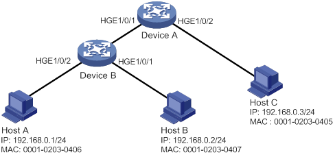
Configuration procedure
1. Configure Device A:
# Configure IP addresses for the interfaces. (Details not shown.)
# Enable IPv4SG on HundredGigE 1/0/2.
<DeviceA> system-view
[DeviceA] interface hundredgige 1/0/2
[DeviceA-HundredGigE1/0/2] ip verify source ip-address mac-address
# On HundredGigE 1/0/2, configure a static IPv4SG binding for Host C.
[DeviceA-HundredGigE1/0/2] ip source binding ip-address 192.168.0.3 mac-address 0001-0203-0405
[DeviceA-HundredGigE1/0/2] quit
# Enable IPv4SG on HundredGigE 1/0/1.
[DeviceA] interface hundredgige 1/0/1
[DeviceA-HundredGigE1/0/1] ip verify source ip-address mac-address
# On HundredGigE 1/0/1, configure a static IPv4SG binding for Host A.
[DeviceA-HundredGigE1/0/1] ip source binding ip-address 192.168.0.1 mac-address 0001-0203-0406
[DeviceA-HundredGigE1/0/1] quit
2. Configure Device B:
# Configure an IP address for each interface. (Details not shown.)
# Enable IPv4SG on HundredGigE 1/0/2.
<DeviceB> system-view
[DeviceB] interface hundredgige 1/0/2
[DeviceB-HundredGigE1/0/2] ip verify source ip-address mac-address
[DeviceB-HundredGigE1/0/2] quit
# Configure a static IPv4SG binding for Host A.
[DeviceB] ip source binding ip-address 192.168.0.1 mac-address 0001-0203-0406
# Enable IPv4SG on HundredGigE 1/0/1.
[DeviceB] interface hundredgige 1/0/1
[DeviceB-HundredGigE1/0/1] ip verify source ip-address mac-address
# On HundredGigE 1/0/1, configure a static IPv4SG binding for Host B.
[DeviceB] interface hundredgige 1/0/1
[DeviceB-HundredGigE1/0/1] ip source binding mac-address 0001-0203-0407
[DeviceB-HundredGigE1/0/1] quit
Verifying the configuration
# Verify that the static IPv4SG bindings are configured successfully on Device A.
<DeviceA> display ip source binding static
Total entries found: 2
IP Address MAC Address Interface VLAN Type
192.168.0.1 0001-0203-0405 HGE1/0/2 N/A Static
192.168.0.3 0001-0203-0406 HGE1/0/1 N/A Static
# Verify that the static IPv4SG bindings are configured successfully on Device B.
<DeviceB> display ip source binding static
Total entries found: 2
IP Address MAC Address Interface VLAN Type
192.168.0.1 0001-0203-0406 N/A N/A Static
N/A 0001-0203-0407 HGE1/0/1 N/A Static
Dynamic IPv4SG using DHCP snooping configuration example
Network requirements
As shown in Figure 38, the host (the DHCP client) obtains an IP address from the DHCP server. Perform the following tasks:
· Enable DHCP snooping on the device to make sure the DHCP client obtains an IP address from the authorized DHCP server. To generate a DHCP snooping entry for the DHCP client, enable recording of client information in DHCP snooping entries.
· Enable dynamic IPv4SG on HundredGigE 1/0/1 to filter incoming packets by using the IPv4SG bindings generated based on DHCP snooping entries. Only packets from the DHCP client are allowed to pass.
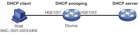
Configuration procedure
1. Configure the DHCP server.
For information about DHCP server configuration, see Layer 3—IP Services Configuration Guide.
2. Configure the device:
# Configure IP addresses for the interfaces. (Details not shown.)
# Enable DHCP snooping.
<Device> system-view
[Device] dhcp snooping enable
# Configure HundredGigE 1/0/2 as a trusted interface.
[Device] interface hundredgige 1/0/2
[Device-HundredGigE1/0/2] dhcp snooping trust
[Device-HundredGigE1/0/2] quit
# Enable IPv4SG on HundredGigE 1/0/1 and verify the source IP address and MAC address for dynamic IPSG.
[Device] interface hundredgige 1/0/1
[Device-HundredGigE1/0/1] ip verify source ip-address mac-address
# Enable recording of client information in DHCP snooping entries on HundredGigE 1/0/1.
[Device-HundredGigE1/0/1] dhcp snooping binding record
[Device-HundredGigE1/0/1] quit
Verifying the configuration
# Verify that a dynamic IPv4SG binding is generated based on a DHCP snooping entry.
[Device] display ip source binding dhcp-snooping
Total entries found: 1
IP Address MAC Address Interface VLAN Type
192.168.0.1 0001-0203-0406 HGE1/0/1 1 DHCP snooping
Dynamic IPv4SG using DHCP relay agent configuration example
Network requirements
As shown in Figure 39, DHCP relay agent is enabled on the switch. The host obtains an IP address from the DHCP server through the DHCP relay agent.
Enable dynamic IPv4SG on VLAN-interface 100 to filter incoming packets by using the IPv4SG bindings generated based on DHCP relay entries.
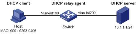
Configuration procedure
1. Configure dynamic IPv4SG:
# Configure IP addresses for the interfaces. (Details not shown.)
# Enable IPv4SG on VLAN-interface 100 and verify the source IP address and MAC address for dynamic IPSG.
<Switch> system-view
[Switch] interface vlan-interface 100
[Switch-Vlan-interface100] ip verify source ip-address mac-address
[Switch-Vlan-interface100] quit
2. Configure the DHCP relay agent:
# Enable the DHCP service.
[Switch] dhcp enable
# Enable recording DHCP relay entries.
[Switch] dhcp relay client-information record
# Configure VLAN-interface 100 to operate in DHCP relay mode.
[Switch] interface vlan-interface 100
[Switch-Vlan-interface100] dhcp select relay
# Specify the IP address of the DHCP server.
[Switch-Vlan-interface100] dhcp relay server-address 10.1.1.1
[Switch-Vlan-interface100] quit
Verifying the configuration
# Verify that a dynamic IPv4SG binding is generated based on a DHCP relay entry.
[Switch] display ip source binding dhcp-relay
Total entries found: 1
IP Address MAC Address Interface VLAN Type
192.168.0.1 0001-0203-0406 Vlan100 100 DHCP relay
Static IPv6SG configuration example
Network requirements
As shown in Figure 40, configure a static IPv6SG binding on HundredGigE 1/0/1 of the device to allow only IPv6 packets from the host to pass.
Configuration procedure
# Enable IPv6SG on HundredGigE 1/0/1.
<Device> system-view
[Device] interface hundredgige 1/0/1
[Device-HundredGigE1/0/1] ipv6 verify source ip-address mac-address
# On HundredGigE 1/0/1, configure a static IPv6SG binding for the host.
[Device-HundredGigE1/0/1] ipv6 source binding ip-address 2001::1 mac-address 0001-0202-0202
[Device-HundredGigE1/0/1] quit
Verifying the configuration
# Verify that the static IPv6SG binding is configured successfully on the device.
[Device] display ipv6 source binding static
Total entries found: 1
IPv6 Address MAC Address Interface VLAN Type
2001::1 0001-0202-0202 HGE1/0/1 N/A Static
Dynamic IPv6SG using DHCPv6 relay agent configuration example
Network requirements
As shown in Figure 41, DHCPv6 relay agent is enabled on the switch. The clients obtain IPv6 addresses from the DHCPv6 server through the DHCPv6 relay agent.
Enable dynamic IPv6SG on VLAN-interface 3 to filter incoming packets by using the IPv6SG bindings generated based on DHCPv6 relay entries.

Configuration procedure
1. Configure the DHCPv6 relay agent:
# Create VLAN 2 and VLAN 3, assign interfaces to the VLANs, and specify IP addresses for VLAN-interface 2 and VLAN-interface 3. (Details not shown.)
# Enable the DHCPv6 relay agent on VLAN-interface 3.
[Switch] interface vlan-interface 3
[Switch-Vlan-interface3] ipv6 dhcp select relay
# Enable recording of DHCPv6 relay entries on the interface.
[Switch-Vlan-interface3] ipv6 dhcp relay client-information record
# Specify the DHCPv6 server address 2::2 on the relay agent.
[Switch-Vlan-interface3] ipv6 dhcp relay server-address 2::2
[Switch-Vlan-interface3] quit
2. Enable IPv6SG on VLAN-interface 3 and verify the source IP address and MAC address for dynamic IPv6SG.
<Switch> system-view
[Switch] interface vlan-interface 3
[Switch-Vlan-interface3] ipv6 verify source ip-address mac-address
[Switch-Vlan-interface3] quit
Verifying the configuration
# Verify that a dynamic IPv6SG binding is generated based on a DHCPv6 relay entry.
[Switch] display ipv6 source binding dhcpv6-relay
Total entries found: 1
IP Address MAC Address Interface VLAN Type
1::2 0001-0203-0406 Vlan3 3 DHCPv6 relay
Configuring ARP attack protection
Although ARP is easy to implement, it provides no security mechanism and is vulnerable to network attacks. An attacker can exploit ARP vulnerabilities to attack network devices in the following ways:
· Acts as a trusted user or gateway to send ARP packets so the receiving devices obtain incorrect ARP entries.
· Sends a large number of unresolvable IP packets to have the receiving device busy with resolving IP addresses until its CPU is overloaded. Unresolvable IP packets refer to IP packets for which ARP cannot find corresponding MAC addresses.
· Sends a large number of ARP packets to overload the CPU of the receiving device.
ARP attack protection configuration task list
|
Tasks at a glance |
|
Flood prevention: · Configuring unresolvable IP attack protection (configured on gateways) ? Configuring ARP source suppression ? Configuring ARP blackhole routing · Configuring ARP packet rate limit (configured on access devices) · Configuring source MAC-based ARP attack detection (configured on gateways) |
|
User and gateway spoofing prevention: · Configuring ARP packet source MAC consistency check (configured on gateways) · Configuring ARP active acknowledgement (configured on gateways) · Configuring authorized ARP (configured on gateways) · Configuring ARP attack detection (configured on access devices) · Configuring ARP scanning and fixed ARP (configured on gateways) · Configuring ARP gateway protection (configured on access devices) · Configuring ARP filtering (configured on access devices) |
Configuring unresolvable IP attack protection
If a device receives a large number of unresolvable IP packets from a host, the following situations can occur:
· The device sends a large number of ARP requests, overloading the target subnets.
· The device keeps trying to resolve the destination IP addresses, overloading its CPU.
To protect the device from such IP attacks, you can configure the following features:
· ARP source suppression—Stops resolving packets from an IP address if the number of unresolvable IP packets from the IP address exceeds the upper limit within 5 seconds. The device continues ARP resolution when the interval elapses. This feature is applicable if the attack packets have the same source addresses.
· ARP blackhole routing—Creates a blackhole route destined for an unresolved IP address. The device drops all matching packets until the blackhole route is deleted. A blackhole route is deleted when its aging timer is reached or the route becomes reachable.
After a blackhole route is created for an unresolved IP address, the device immediately starts the first ARP blackhole route probe by sending an ARP request. If the resolution fails, the device continues probing according to the probe settings. If the IP address resolution succeeds in a probe, the device converts the blackhole route to a normal route. If an ARP blackhole route ages out before the device finishes all probes, the device deletes the blackhole route and does not perform the remaining probes.
This feature is applicable regardless of whether the attack packets have the same source addresses.
Configuring ARP source suppression
|
Command |
Remarks |
|
|
1. Enter system view. |
system-view |
N/A |
|
2. Enable ARP source suppression. |
arp source-suppression enable |
By default, ARP source suppression is disabled. |
|
3. Set the maximum number of unresolvable packets that the device can process per source IP address within 5 seconds. |
arp source-suppression limit limit-value |
By default, the maximum number is 10. |
Configuring ARP blackhole routing
|
Step |
Command |
Remarks |
|
1. Enter system view. |
system-view |
N/A |
|
2. Enable ARP blackhole routing. |
arp resolving-route enable |
By default, ARP blackhole routing is enabled. |
|
3. (Optional.) Set the number of ARP blackhole route probes for each unresolved IP address. |
arp resolving-route probe-count count |
The default setting is three probes. Set the ARP blackhole route probe count to a big value, for example, 25. If the device fails to reach the destination IP address temporarily and the probe count is too small, all probes might finish before the problem is resolved. As a result, non-attack packets will be dropped. This setting can avoid such situation. |
|
4. (Optional.) Set the interval at which the device probes ARP blackhole routes. |
arp resolving-route probe-interval interval |
The default setting is 1 second. |
Displaying and maintaining unresolvable IP attack protection
Execute display commands in any view.
|
Task |
Command |
|
Display ARP source suppression configuration information. |
display arp source-suppression |
Configuration example
Network requirements
As shown in Figure 42, a LAN contains two areas: an R&D area in VLAN 10 and an office area in VLAN 20. Each area connects to the gateway (Device) through an access switch.
A large number of ARP requests are detected in the office area and are considered an attack caused by unresolvable IP packets. To prevent the attack, configure ARP source suppression or ARP blackhole routing.

Configuration procedure
· If the attack packets have the same source address, configure ARP source suppression:
# Enable ARP source suppression.
<Device> system-view
[Device] arp source-suppression enable
# Configure the device to process a maximum of 100 unresolvable packets per source IP address within 5 seconds.
[Device] arp source-suppression limit 100
· If the attack packets have different source addresses, configure ARP blackhole routing:
# Enable ARP blackhole routing.
[Device] arp resolving-route enable
Configuring ARP packet rate limit
The ARP packet rate limit feature allows you to limit the rate of ARP packets delivered to the CPU. An ARP attack detection-enabled device will send all received ARP packets to the CPU for inspection. Processing excessive ARP packets will make the device malfunction or even crash. To solve this problem, configure ARP packet rate limit.
Configuration guidelines
Configure this feature when ARP attack detection, ARP snooping, or ARP fast-reply is enabled, or when ARP flood attacks are detected.
Configuration procedure
This task sets a rate limit for ARP packets received on an interface. When the receiving rate of ARP packets on the interface exceeds the rate limit, those packets are discarded.
You can enable sending notifications to the SNMP module or enable logging for ARP packet rate limit.
· If notification sending is enabled, the device sends the highest threshold-crossed ARP packet rate within the sending interval in a notification to the SNMP module. You must use the snmp-agent target-host command to set the notification type and target host. For more information about notifications, see Network Management and Monitoring Command Reference.
· If logging for ARP packet rate limit is enabled, the device sends the highest threshold-crossed ARP packet rate within the sending interval in a log message to the information center. You can configure the information center module to set the log output rules. For more information about information center, see Network Management and Monitoring Configuration Guide.
To configure ARP packet rate limit:
|
Step |
Command |
Remarks |
|
1. Enter system view. |
system-view |
N/A |
|
2. (Optional.) Enable notification sending for ARP packet rate limit. |
snmp-agent trap enable arp [ rate-limit ] |
By default, notification sending for ARP packet rate limit is disabled. |
|
3. (Optional.) Enable logging for ARP packet rate limit. |
arp rate-limit log enable |
By default, logging for ARP packet rate limit is disabled. |
|
4. (Optional.) Set the notification and log message sending interval. |
arp rate-limit log interval interval |
By default, the device sends notifications and log messages every 60 seconds. |
|
5. Enter Layer 2 Ethernet interface, Layer 2 aggregate interface, Layer 3 Ethernet interface, or Layer 3 aggregate interface view. |
interface interface-type interface-number |
N/A |
|
6. Enable ARP packet rate limit. |
arp rate-limit [ pps ] |
By default, ARP packet rate limit is enabled. |
|
|
NOTE: If you enable notification sending and logging for ARP packet rate limit on a Layer 2 aggregate interface, the features apply to all aggregation member ports. |
Configuring source MAC-based ARP attack detection
This feature checks the number of ARP packets delivered to the CPU. If the number of packets from the same MAC address within 5 seconds exceeds a threshold, the device generates an ARP attack entry for the MAC address. Before the entry ages out, the device handles the attack by using either of the following methods:
· Monitor—Only generates log messages.
· Filter—Generates log messages and filters out subsequent ARP packets from the MAC address.
Make sure you have enabled the ARP logging feature before enabling the source MAC-based ARP attack detection feature. For information about the ARP logging feature, see Layer 3—IP Services Configuration Guide.
You can exclude the MAC addresses of some gateways and servers from this detection. This feature does not inspect ARP packets from those devices even if they are attackers.
Configuration procedure
To configure source MAC-based ARP attack detection:
|
Step |
Command |
Remarks |
|
1. Enter system view. |
system-view |
N/A |
|
2. Enable source MAC-based ARP attack detection and specify the handling method. |
arp source-mac { filter | monitor } |
By default, this feature is disabled. When you change the handling method from monitor to filter, the configuration takes effect immediately. When you change the handling method from filter to monitor, the device continues filtering packets that match existing attack entries. |
|
3. Set the threshold. |
arp source-mac threshold threshold-value |
The default threshold is 30. |
|
4. Set the aging timer for ARP attack entries. |
arp source-mac aging-time time |
By default, the lifetime is 300 seconds. |
|
5. (Optional.) Exclude specific MAC addresses from this detection. |
arp source-mac exclude-mac mac-address&<1-10> |
By default, no MAC address is excluded. |
|
|
NOTE: When an ARP attack entry is aged out, ARP packets sourced from the MAC address in the entry can be processed correctly. |
Displaying and maintaining source MAC-based ARP attack detection
Execute display commands in any view.
|
Task |
Command |
|
(In standalone mode.) Display ARP attack entries detected by source MAC-based ARP attack detection. |
display arp source-mac { slot slot-number | interface interface-type interface-number } |
|
(In IRF mode.) Display ARP attack entries detected by source MAC-based ARP attack detection. |
display arp source-mac { chassis chassis-number slot slot-number | interface interface-type interface-number } |
Configuration example
Network requirements
As shown in Figure 43, the hosts access the Internet through a gateway (Device). If malicious users send a large number of ARP requests to the gateway, the gateway might crash and cannot process requests from the clients. To solve this problem, configure source MAC-based ARP attack detection on the gateway.
Figure 43 Network diagram
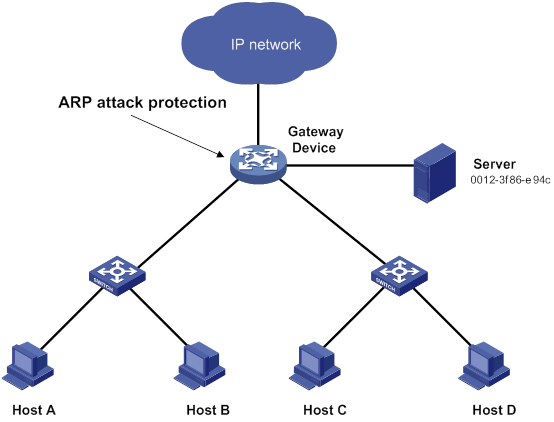
Configuration considerations
An attacker might forge a large number of ARP packets by using the MAC address of a valid host as the source MAC address. To prevent such attacks, configure the gateway in the following steps:
1. Enable source MAC-based ARP attack detection and specify the handling method as filter.
2. Set the threshold.
3. Set the lifetime for ARP attack entries.
4. Exclude the MAC address of the server from this detection.
Configuration procedure
# Enable source MAC-based ARP attack detection, and specify the handling method as filter.
<Device> system-view
[Device] arp source-mac filter
# Set the threshold to 30.
[Device] arp source-mac threshold 30
# Set the lifetime for ARP attack entries to 60 seconds.
[Device] arp source-mac aging-time 60
# Exclude MAC address 0012-3f86-e94c from this detection.
[Device] arp source-mac exclude-mac 0012-3f86-e94c
Configuring ARP packet source MAC consistency check
This feature enables a gateway to filter out ARP packets in which source MAC address in the Ethernet header is different from the sender MAC address in the message body. This feature allows the gateway to learn correct ARP entries.
To enable ARP packet source MAC address consistency check:
|
Step |
Command |
Remarks |
|
1. Enter system view. |
system-view |
N/A |
|
2. Enable ARP packet source MAC address consistency check. |
arp valid-check enable |
By default, ARP packet source MAC address consistency check is disabled. |
Configuring ARP active acknowledgement
Configure this feature on gateways to prevent user spoofing.
ARP active acknowledgement prevents a gateway from generating incorrect ARP entries.
In strict mode, a gateway performs more strict validity checks before creating an ARP entry:
· Upon receiving an ARP request destined for the gateway, the gateway sends an ARP reply but does not create an ARP entry.
· Upon receiving an ARP reply, the gateway determines whether it has resolved the sender IP address:
? If yes, the gateway performs active acknowledgement. When the ARP reply is verified as valid, the gateway creates an ARP entry.
? If no, the gateway discards the packet.
For ARP active acknowledgement to take effect in strict mode, make sure ARP blackhole routing is enabled.
To configure ARP active acknowledgement:
|
Step |
Command |
Remarks |
|
1. Enter system view. |
system-view |
N/A |
|
2. Enable the ARP active acknowledgement feature. |
arp active-ack [ strict ] enable |
By default, this feature is disabled. |
Configuring authorized ARP
Authorized ARP entries are generated based on the DHCP clients' address leases on the DHCP server or dynamic client entries on the DHCP relay agent. For more information about DHCP server and DHCP relay agent, see Layer 3—IP Services Configuration Guide.
With authorized ARP enabled, an interface is disabled from learning dynamic ARP entries. This feature prevents user spoofing and allows only authorized clients to access network resources.
Configuration procedure
To enable authorized ARP:
|
Step |
Command |
Remarks |
|
1. Enter system view. |
system-view |
N/A |
|
2. Enter interface view. |
interface interface-type interface-number |
The following interface types are supported: · Layer 3 Ethernet interfaces. · Layer 3 Ethernet subinterfaces. · Layer 3 aggregate interfaces. · Layer 3 aggregate subinterfaces. · VLAN interfaces. |
|
3. Enable authorized ARP on the interface. |
arp authorized enable |
By default, authorized ARP is disabled. |
Configuration example (on a DHCP server)
Network requirements
As shown in Figure 44, configure authorized ARP on HundredGigE 1/0/1 of Device A (a DHCP server) to ensure user validity.
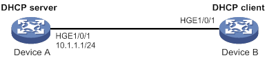
Configuration procedure
1. Configure Device A:
# Specify the IP address for HundredGigE 1/0/1.
<DeviceA> system-view
[DeviceA] interface hundredgige 1/0/1
[DeviceA-HundredGigE1/0/1] ip address 10.1.1.1 24
[DeviceA-HundredGigE1/0/1] quit
# Configure DHCP.
[DeviceA] dhcp enable
[DeviceA] dhcp server ip-pool 1
[DeviceA-dhcp-pool-1] network 10.1.1.0 mask 255.255.255.0
[DeviceA-dhcp-pool-1] quit
# Enter Layer 3 Ethernet interface view.
[DeviceA] interface hundredgige 1/0/1
# Enable authorized ARP.
[DeviceA-HundredGigE1/0/1] arp authorized enable
[DeviceA-HundredGigE1/0/1] quit
2. Configure Device B:
<DeviceB> system-view
[DeviceB] interface hundredgige 1/0/1
[DeviceB-HundredGigE1/0/1] ip address dhcp-alloc
[DeviceB-HundredGigE1/0/1] quit
Verifying the configuration
# Display authorized ARP entry information on Device A.
[DeviceA] display arp all
Type: S-Static D-Dynamic O-Openflow R-Rule M-Multiport I-Invalid
IP Address MAC Address VID Interface/Link ID Aging Type
10.1.1.2 0012-3f86-e94c N/A HGE1/0/1 16 D
The output shows that IP address 10.1.1.2 has been assigned to Device B.
Device B must use the IP address and MAC address in the authorized ARP entry to communicate with Device A. Otherwise, the communication fails. Thus user validity is ensured.
Configuration example (on a DHCP relay agent)
Network requirements
As shown in Figure 45, configure authorized ARP on HundredGigE 1/0/2 of Device B (a DHCP relay agent) to ensure user validity.
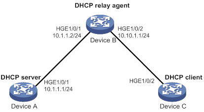
Configuration procedure
1. Configure Device A:
# Specify the IP address for HundredGigE 1/0/1.
<DeviceA> system-view
[DeviceA] interface hundredgige 1/0/1
[DeviceA-HundredGigE1/0/1] ip address 10.1.1.1 24
[DeviceA-HundredGigE1/0/1] quit
# Configure DHCP.
[DeviceA] dhcp enable
[DeviceA] dhcp server ip-pool 1
[DeviceA-dhcp-pool-1] network 10.10.1.0 mask 255.255.255.0
[DeviceA-dhcp-pool-1] gateway-list 10.10.1.1
[DeviceA-dhcp-pool-1] quit
[DeviceA] ip route-static 10.10.1.0 24 10.1.1.2
2. Configure Device B:
# Enable DHCP.
<DeviceB> system-view
[DeviceB] dhcp enable
# Specify the IP addresses of HundredGigE 1/0/1 and HundredGigE 1/0/2.
[DeviceB] interface hundredgige 1/0/1
[DeviceB-HundredGigE1/0/1] ip address 10.1.1.2 24
[DeviceB-HundredGigE1/0/1] quit
[DeviceB] interface hundredgige 1/0/2
[DeviceB-HundredGigE1/0/2] ip address 10.10.1.1 24
# Enable DHCP relay agent on HundredGigE 1/0/2.
[DeviceB-HundredGigE1/0/2] dhcp select relay
# Add the DHCP server 10.1.1.1 to DHCP server group 1.
[DeviceB-HundredGigE1/0/2] dhcp relay server-address 10.1.1.1
# Enable authorized ARP.
[DeviceB-HundredGigE1/0/2] arp authorized enable
[DeviceB-HundredGigE1/0/2] quit
# Enable recording of relay entries on the relay agent.
[DeviceB] dhcp relay client-information record
3. Configure Device C:
<DeviceC> system-view
[DeviceC] ip route-static 10.1.1.0 24 10.10.1.1
[DeviceC] interface hundredgige 1/0/2
[DeviceC-HundredGigE1/0/2] ip address dhcp-alloc
[DeviceC-HundredGigE1/0/2] quit
Verifying the configuration
# Display authorized ARP information on Device B.
[DeviceB] display arp all
Type: S-Static D-Dynamic O-Openflow R-Rule M-Multiport I-Invalid
IP Address MAC Address VID Interface/Link ID Aging Type
10.10.1.2 0012-3f86-e94c N/A HGE1/0/2 16 D
The output shows that Device A assigned the IP address 10.10.1.2 to Device C.
Device C must use the IP address and MAC address in the authorized ARP entry to communicate with Device B. Otherwise, the communication fails. Thus the user validity is ensured.
Configuring ARP attack detection
ARP attack detection enables access devices to block ARP packets from unauthorized clients to prevent user spoofing and gateway spoofing attacks. ARP attack detection does not check ARP packets received from ARP trusted interfaces.
ARP attack detection provides the following features:
· User validity check.
· ARP packet validity check.
· ARP restricted forwarding.
· ARP attack detection logging.
If both ARP packet validity check and user validity check are enabled, the former one applies first, and then the latter applies.
Configuring user validity check
User validity check compares the sender IP and sender MAC in the received ARP packet with static IP source guard bindings and DHCP snooping entries.
· If a match is found, the device forwards the ARP packet.
· If no match is found, the device discards the ARP packet.
Static IP source guard bindings are created by using the ip source binding command. For more information, see "Configuring IP source guard."
DHCP snooping entries are automatically generated by DHCP snooping. For more information, see Layer 3—IP Services Configuration Guide.
Configuration guidelines
When you configure user validity check, follow these guidelines:
· Make sure one or more of the following items are configured for user validity check:
? Static IP source guard bindings.
? DHCP snooping.
If none of the items is configured, all incoming ARP packets on ARP untrusted interfaces are discarded.
· Specify the VLAN where ARP attack detection is enabled as the VLAN for IP source guard bindings. Otherwise, the IP source guard bindings do not take effect for user validity check.
Configuration procedure
To configure user validity check:
|
Step |
Command |
Remarks |
|
1. Enter system view. |
system-view |
N/A |
|
2. Enter VLAN view. |
vlan vlan-id |
N/A |
|
3. Enable ARP attack detection. |
arp detection enable |
By default, ARP attack detection is disabled. |
|
4. Return to system view. |
quit |
N/A |
|
5. Enter Layer 2 Ethernet interface view or Layer 2 aggregate interface view. |
interface interface-type interface-number |
N/A |
|
6. (Optional.) Configure the interface as a trusted interface excluded from ARP attack detection. |
arp detection trust |
By default, an interface is untrusted. |
Configuring ARP packet validity check
Enable validity check for ARP packets received on untrusted interfaces and specify the following objects to be checked:
· src-mac—Checks whether the sender MAC address in the message body is identical to the source MAC address in the Ethernet header. If they are identical, the packet is forwarded. Otherwise, the packet is discarded.
· dst-mac—Checks the target MAC address of ARP replies. If the target MAC address is all-zero, all-one, or inconsistent with the destination MAC address in the Ethernet header, the packet is considered invalid and discarded.
· ip—Checks the sender and target IP addresses of ARP replies, and the sender IP address of ARP requests. All-one or multicast IP addresses are considered invalid and the corresponding packets are discarded.
To configure ARP packet validity check:
|
Step |
Command |
Remarks |
|
1. Enter system view. |
system-view |
N/A |
|
2. Enter VLAN view. |
vlan vlan-id |
N/A |
|
3. Enable ARP attack detection. |
arp detection enable |
By default, ARP attack detection is disabled. |
|
4. Return to system view. |
quit |
N/A |
|
5. Enable ARP packet validity check and specify the objects to be checked. |
arp detection validate { dst-mac | ip | src-mac } * |
By default, ARP packet validity check is disabled. |
|
6. Enter Layer 2 Ethernet interface view or Layer 2 aggregate interface view. |
interface interface-type interface-number |
N/A |
|
7. (Optional.) Configure the interface as a trusted interface excluded from ARP attack detection. |
arp detection trust |
By default, an interface is untrusted. |
Configuring ARP restricted forwarding
|
|
NOTE: ARP restricted forwarding does not apply to ARP packets with multiport MAC as their destination MAC addresses. |
ARP restricted forwarding controls the forwarding of ARP packets that are received on untrusted interfaces and have passed user validity check as follows:
· If the packets are ARP requests, they are forwarded through the trusted interface.
· If the packets are ARP replies, they are forwarded according to their destination MAC address. If no match is found in the MAC address table, they are forwarded through the trusted interface.
Configure user validity check before you configure ARP restricted forwarding.
To enable ARP restricted forwarding:
|
Step |
Command |
Remarks |
|
1. Enter system view. |
system-view |
N/A |
|
2. Enter VLAN view. |
vlan vlan-id |
N/A |
|
3. Enable ARP restricted forwarding. |
arp restricted-forwarding enable |
By default, ARP restricted forwarding is disabled. |
Enabling ARP attack detection logging
The ARP attack detection logging feature enables a device to generate ARP attack detection log messages when illegal ARP packets are detected. An ARP attack detection log message contains the following information:
1. Receiving interface of the ARP packets.
2. Sender IP address.
3. Total number of dropped ARP packets.
To enable ARP attack detection logging:
|
Step |
Command |
Remarks |
|
1. Enter system view. |
system-view |
N/A |
|
2. Enable ARP attack detection logging. |
arp detection log enable |
By default, ARP attack detection logging is disabled. |
Displaying and maintaining ARP attack detection
Execute display commands in any view and reset commands in user view.
|
Task |
Command |
|
Display the VLANs enabled with ARP attack detection. |
display arp detection |
|
Display the ARP attack detection statistics. |
display arp detection statistics [ interface interface-type interface-number ] |
|
Clear the ARP attack detection statistics. |
reset arp detection statistics [ interface interface-type interface-number ] |
User validity check and ARP packet validity check configuration example
Network requirements
As shown in Figure 46, configure Device B to perform ARP packet validity check and user validity check based on static IP source guard bindings and DHCP snooping entries for connected hosts.

Configuration procedure
1. Add all interfaces on Device B to VLAN 10, and specify the IP address of VLAN-interface 10 on Device A. (Details not shown.)
2. Configure the DHCP server on Device A, and configure DHCP address pool 0.
<DeviceA> system-view
[DeviceA] dhcp enable
[DeviceA] dhcp server ip-pool 0
[DeviceA-dhcp-pool-0] network 10.1.1.0 mask 255.255.255.0
3. Configure Host A (DHCP client) and Host B. (Details not shown.)
4. Configure Device B:
# Enable DHCP snooping.
<DeviceB> system-view
[DeviceB] dhcp snooping enable
[DeviceB] interface hundredgige 1/0/3
[DeviceB-HundredGigE1/0/3] dhcp snooping trust
[DeviceB-HundredGigE1/0/3] quit
# Enable recording of client information in DHCP snooping entries on HundredGigE 1/0/1.
[DeviceB] interface hundredgige 1/0/1
[DeviceB-HundredGigE1/0/1] dhcp snooping binding record
[DeviceB-HundredGigE1/0/1] quit
# Enable ARP attack detection for VLAN 10.
[DeviceB] vlan 10
[DeviceB-vlan10] arp detection enable
# Configure the upstream interface as a trusted interface. By default, an interface is an untrusted interface.
[DeviceB-vlan10] interface hundredgige 1/0/3
[DeviceB-HundredGigE1/0/3] arp detection trust
[DeviceB-HundredGigE1/0/3] quit
# Configure a static IP source guard binding entry on interface HundredGigE 1/0/2 for user validity check.
[DeviceB] interface hundredgige 1/0/2
[DeviceB-HundredGigE1/0/2] ip source binding ip-address 10.1.1.6 mac-address 0001-0203-0607 vlan 10
[DeviceB-HundredGigE1/0/2] quit
# Enable ARP packet validity check by checking the MAC addresses and IP addresses of ARP packets.
[DeviceB] arp detection validate dst-mac ip src-mac
After the configurations are completed, Device B first checks the validity of ARP packets received on HundredGigE 1/0/1 and HundredGigE 1/0/2. If the ARP packets are confirmed valid, Device B performs user validity check by using the static IP source guard bindings and finally DHCP snooping entries.
ARP restricted forwarding configuration example
Network requirements
As shown in Figure 47, configure ARP restricted forwarding on Device B where ARP attack detection is configured. Port isolation configured on Device B can take effect for broadcast ARP requests.
Configuration procedure
1. Configure VLAN 10, add interfaces to VLAN 10, and specify the IP address of VLAN-interface 10 on Device A. (Details not shown.)
2. Configure the DHCP server on Device A, and configure DHCP address pool 0.
<DeviceA> system-view
[DeviceA] dhcp enable
[DeviceA] dhcp server ip-pool 0
[DeviceA-dhcp-pool-0] network 10.1.1.0 mask 255.255.255.0
3. Configure Host A (DHCP client) and Host B. (Details not shown.)
4. Configure Device B:
# Enable DHCP snooping, and configure HundredGigE 1/0/3 as a DHCP trusted interface.
<DeviceB> system-view
[DeviceB] dhcp snooping enable
[DeviceB] interface hundredgige 1/0/3
[DeviceB-HundredGigE1/0/3] dhcp snooping trust
[DeviceB-HundredGigE1/0/3] quit
# Enable ARP attack detection for user validity check.
[DeviceB] vlan 10
[DeviceB-vlan10] arp detection enable
# Configure HundredGigE 1/0/3 as an ARP trusted interface.
[DeviceB-vlan10] interface hundredgige 1/0/3
[DeviceB-HundredGigE1/0/3] arp detection trust
[DeviceB-HundredGigE1/0/3] quit
# Configure a static IP source guard entry on interface HundredGigE 1/0/2.
[DeviceB] interface hundredgige 1/0/2
[DeviceB-HundredGigE1/0/2] ip source binding ip-address 10.1.1.6 mac-address 0001-0203-0607 vlan 10
[DeviceB-HundredGigE1/0/2] quit
# Enable ARP packet validity check by checking the MAC addresses and IP addresses of ARP packets.
[DeviceB] arp detection validate dst-mac ip src-mac
# Configure port isolation.
[DeviceB] port-isolate group 1
[DeviceB] interface hundredgige 1/0/1
[DeviceB-HundredGigE1/0/1] port-isolate enable group 1
[DeviceB-HundredGigE1/0/1] quit
[DeviceB] interface hundredgige 1/0/2
[DeviceB-HundredGigE1/0/2] port-isolate enable group 1
[DeviceB-HundredGigE1/0/2] quit
After the configurations are completed, Device B first checks the validity of ARP packets received on HundredGigE 1/0/1 and HundredGigE 1/0/2. If the ARP packets are confirmed valid, Device B performs user validity check by using the static IP source guard bindings and finally DHCP snooping entries. However, ARP broadcast requests sent from Host A can pass the check on Device B and reach Host B. Port isolation fails.
# Enable ARP restricted forwarding.
[DeviceB] vlan 10
[DeviceB-vlan10] arp restricted-forwarding enable
[DeviceB-vlan10] quit
After the configuration is completed, Device B forwards ARP broadcast requests from Host A to Device A through the trusted interface HundredGigE 1/0/3. Host B cannot receive such packets. Port isolation operates correctly.
Configuring ARP scanning and fixed ARP
ARP scanning is typically used together with the fixed ARP feature in small-scale networks.
ARP scanning automatically creates ARP entries for devices in an address range. The device performs ARP scanning in the following steps:
1. Sends ARP requests for each IP address in the address range.
2. Obtains their MAC addresses through received ARP replies.
3. Creates dynamic ARP entries.
Fixed ARP converts existing dynamic ARP entries (including those generated through ARP scanning) to static ARP entries. This feature prevents ARP entries from being modified by attackers. Static ARP entries can also be manually configured by the arp static command.
Configuration restrictions and guidelines
Follow these restrictions and guidelines when you configure ARP scanning and fixed ARP:
· IP addresses in existing ARP entries are not scanned.
· ARP scanning will take some time. To stop an ongoing scan, press Ctrl + C. Dynamic ARP entries are created based on ARP replies received before the scan is terminated.
· The arp fixup command is a one-time operation. You can use this command again to convert the dynamic ARP entries learned later to static.
· Due to the limit on the total number of static ARP entries, some dynamic ARP entries might fail the conversion.
· To delete a static ARP entry converted from a dynamic one, use the undo arp ip-address [ vpn-instance-name ] command. Use the reset arp all command to delete all ARP entries or the reset arp static command to delete all static ARP entries.
Configuration procedure
To configure ARP scanning and fixed ARP:
|
Step |
Command |
|
1. Enter system view. |
system-view |
|
2. Enter interface view. |
interface interface-type interface-number |
|
3. Trigger an ARP scanning. |
arp scan [ start-ip-address to end-ip-address ] |
|
4. Return to system view. |
quit |
|
5. Convert existing dynamic ARP entries to static ARP entries. |
arp fixup |
Configuring ARP gateway protection
Configure this feature on interfaces not connected with a gateway to prevent gateway spoofing attacks.
When such an interface receives an ARP packet, it checks whether the sender IP address in the packet is consistent with that of any protected gateway. If yes, it discards the packet. If not, it handles the packet correctly.
Configuration guidelines
Follow these guidelines when you configure ARP gateway protection:
· You can enable ARP gateway protection for a maximum of eight gateways on an interface.
· Do not configure both the arp filter source and arp filter binding commands on an interface.
· If ARP gateway protection works with ARP attack detection, ARP snooping, and ARP fast-reply, ARP gateway protection applies first.
Configuration procedure
To configure ARP gateway protection:
|
Step |
Command |
Remarks |
|
|
1. Enter system view. |
system-view |
N/A |
|
|
2. Enter Layer 2 Ethernet interface and Layer 2 aggregate interface view. |
interface interface-type interface-number |
N/A |
|
|
3. Enable ARP gateway protection for the specified gateway. |
arp filter source ip-address |
By default, ARP gateway protection is disabled. |
|
Configuration example
Network requirements
As shown in Figure 48, Host B launches gateway spoofing attacks to Device B. As a result, traffic that Device B intends to send to Device A is sent to Host B.
Configure Device B to block such attacks.
Configuration procedure
# Configure ARP gateway protection on Device B.
<DeviceB> system-view
[DeviceB] interface hundredgige 1/0/1
[DeviceB-HundredGigE1/0/1] arp filter source 10.1.1.1
[DeviceB-HundredGigE1/0/1] quit
[DeviceB] interface hundredgige 1/0/2
[DeviceB-HundredGigE1/0/2] arp filter source 10.1.1.1
Verifying the configuration
# Verify that HundredGigE 1/0/1 and HundredGigE 1/0/2 discard the incoming ARP packets in which sender IP address is the IP address of the gateway.
Configuring ARP filtering
The ARP filtering feature can prevent gateway spoofing and user spoofing attacks.
An interface enabled with this feature checks the sender IP and MAC addresses in a received ARP packet against permitted entries. If a match is found, the packet is handled correctly. If not, the packet is discarded.
Configuration guidelines
Follow these guidelines when you configure ARP filtering:
· You can configure a maximum of eight permitted entries on an interface.
· Do not configure both the arp filter source and arp filter binding commands on an interface.
· If ARP filtering works with ARP attack detection, ARP snooping, and ARP fast-reply, ARP filtering applies first.
Configuration procedure
To configure ARP filtering:
|
Step |
Command |
Remarks |
|
1. Enter system view. |
system-view |
N/A |
|
2. Enter Layer 2 Ethernet interface or Layer 2 aggregate interface view. |
interface interface-type interface-number |
N/A |
|
3. Enable ARP filtering and configure a permitted entry. |
arp filter binding ip-address mac-address |
By default, ARP filtering is disabled. |
Configuration example
Network requirements
As shown in Figure 49, the IP and MAC addresses of Host A are 10.1.1.2 and 000f-e349-1233, respectively. The IP and MAC addresses of Host B are 10.1.1.3 and 000f-e349-1234, respectively.
Configure ARP filtering on HundredGigE 1/0/1 and HundredGigE 1/0/2 of Device B to permit ARP packets from only Host A and Host B.
Configuration procedure
# Configure ARP filtering on Device B.
<DeviceB> system-view
[DeviceB] interface hundredgige 1/0/1
[DeviceB-HundredGigE1/0/1] arp filter binding 10.1.1.2 000f-e349-1233
[DeviceB-HundredGigE1/0/1] quit
[DeviceB] interface hundredgige 1/0/2
[DeviceB-HundredGigE1/0/2] arp filter binding 10.1.1.3 000f-e349-1234
Verifying the configuration
# Verify that HundredGigE 1/0/1 permits ARP packets from Host A and discards other ARP packets.
# Verify that HundredGigE 1/0/2 permits ARP packets from Host B and discards other ARP packets.
Configuring ND attack defense
Overview
IPv6 Neighbor Discovery (ND) attack defense is able to identify forged ND messages to prevent ND attacks.
The IPv6 ND protocol does not provide any security mechanisms and is vulnerable to network attacks. An attacker can send the following forged ICMPv6 messages to perform ND attacks:
· Forged NS/NA/RS messages with an IPv6 address of a victim host. The gateway and other hosts update the ND entry for the victim with incorrect address information. As a result, all packets intended for the victim are sent to the attacking terminal.
· Forged RA messages with the IPv6 address of a victim gateway. As a result, all hosts attached to the victim gateway maintain incorrect IPv6 configuration parameters and ND entries.
For information about the IPv6 ND protocol, see Layer 3–IP Services Configuration Guide.
Table 10 ND attack defense features at a glance
|
ND attack defense feature |
To block |
|
Source MAC consistency check (applicable to gateways) |
ND messages in which the Ethernet frame header and the source link-layer address option of the ND message contain different source MAC addresses. |
Enabling source MAC consistency check for ND messages
The source MAC consistency check feature is typically configured on gateways to prevent ND attacks.
This feature checks the source MAC address and the source link-layer address for consistency for each arriving ND message.
· If the source MAC address and the source link-layer address are not the same, the device drops the packet.
· If the addresses are the same, the device continues learning ND entries.
The ND logging feature logs source MAC inconsistency events, and it sends the log messages to the information center. The information center can then output log messages from different source modules to different destinations. For more information about the information center, see Network Management and Monitoring Configuration Guide.
To enable source MAC consistency check for ND messages:
|
Step |
Command |
Remarks |
|
1. Enter system view. |
system-view |
N/A |
|
2. Enable source MAC consistency check for ND messages. |
ipv6 nd mac-check enable |
By default, source MAC consistency check is disabled for ND messages. |
|
3. (Optional.) Enable the ND logging feature. |
ipv6 nd check log enable |
By default, the ND logging feature is disabled. As a best practice, disable the ND logging feature to avoid excessive ND logs. |
Configuring uRPF
Overview
Unicast Reverse Path Forwarding (uRPF) protects a network against source address spoofing attacks, such as DoS and DDoS attacks.
Attackers send packets with a forged source address to access a system that uses IP-based authentication, in the name of authorized users or even the administrator. Even if the attackers or other hosts cannot receive any response packets, the attacks are still disruptive to the attacked target.
Figure 50 Source address spoofing attack
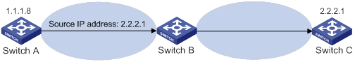
As shown in Figure 50, an attacker on Switch A sends the server (Switch B) requests with a forged source IP address 2.2.2.1 at a high rate. Switch B sends response packets to IP address 2.2.2.1 (Switch C). Consequently, both Switch B and Switch C are attacked. If the administrator disconnects Switch C by mistake, the network service is interrupted.
Attackers can also send packets with different forged source addresses or attack multiple servers simultaneously to block connections or even break down the network.
uRPF can prevent these source address spoofing attacks. It checks whether an interface that receives a packet is the output interface of the FIB entry that matches the source address of the packet. If not, uRPF considers it a spoofing attack and discards the packet.
uRPF check modes
uRPF supports strict and loose modes.
· Strict uRPF check—To pass strict uRPF check, the source address of a packet and the receiving interface must match the destination address and output interface of a FIB entry. In some scenarios (for example, asymmetrical routing), strict uRPF might discard valid packets. Strict uRPF is often deployed between a PE and a CE.
· Loose uRPF check—To pass loose uRPF check, the source address of a packet must match the destination address of a FIB entry. Loose uRPF can avoid discarding valid packets, but might let go attack packets. Loose uRPF is often deployed between ISPs, especially in asymmetrical routing.
uRPF operation
uRPF does not check multicast packets.
Figure 51 shows how uRPF works.
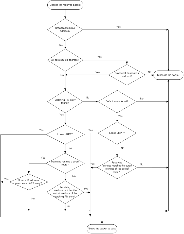
1. uRPF checks source address validity:
? uRPF discards packets with a broadcast source address.
? uRPF discards packets with an all-zero source address but a non-broadcast destination address. (A packet with source address 0.0.0.0 and destination address 255.255.255.255 might be a DHCP packet and cannot be discarded.)
? uRPF proceeds to step 2 for other packets.
2. uRPF checks whether the source address matches a FIB entry:
? If yes, uRPF proceeds to step 3.
? If no, uRPF proceeds to step 6.
3. uRPF checks whether the check mode is loose:
? If yes, uRPF proceeds to step 8.
? If no, uRPF checks whether the matching route is a direct route:
- If yes, uRPF proceeds to step 5.
- If no, uRPF proceeds to step 4.
4. uRPF checks whether the receiving interface matches the output interface of the matching FIB entry:
? If yes, uRPF proceeds to step 8.
? If no, uRPF proceeds to step 9.
5. uRPF checks whether the source IP address matches an ARP entry:
? If yes, uRPF proceeds to step 8.
? If no, uRPF proceeds to step 9.
6. uRPF checks whether the FIB table has a default route:
? If yes, uRPF proceeds to step 7.
? If no, uRPF proceeds to step 9.
7. uRPF checks whether the check mode is loose:
? If yes, uRPF proceeds to step 8.
? If no, uRPF checks whether the output interface of the default route matches the receiving interface of the packet:
- If yes, uRPF proceeds to step 8.
- If no, uRPF proceeds to step 9.
8. The packet passes the check and is forwarded.
9. The packet is discarded.
Network application
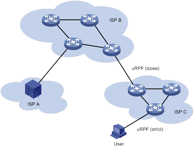
As shown in Figure 52, strict uRPF check is configured between an ISP network and a customer network. Loose uRPF check is configured between ISPs.
Enabling uRPF
uRPF checks only incoming packets on interfaces. You can enable uRPF globally or on an interface. Global uRPF takes effect on all interfaces of the device. uRPF enabled on an interface takes effect only on the interface.
Follow these guidelines when you enable uRPF:
· If you configure uRPF globally and on an interface, the interface preferentially uses the interface-specific settings.
· After you enable the uRPF feature on the switch, the routing table size might decrease by half.
· If the number of routes exceeds half the routing table size of the switch, the uRPF feature cannot be enabled to avoid loss of routes and packets.
· VLAN interfaces support loose and strict uRPF.
· The following interfaces support only loose uRPF. Even if strict uRPF is enabled globally or on these interfaces, the interfaces still perform loose uRPF.
? Layer 3 Ethernet interfaces.
? Layer 3 Ethernet subinterfaces.
? Layer 3 aggregate interfaces.
? Layer 3 aggregate subinterfaces.
To enable uRPF globally:
|
Step |
Command |
Remarks |
|
1. Enter system view. |
system-view |
N/A |
|
2. Enable uRPF globally. |
ip urpf { loose | strict } |
By default, uRPF is disabled. |
To enable uRPF on an interface:
|
Step |
Command |
Remarks |
|
1. Enter system view. |
system-view |
N/A |
|
2. Enter interface view. |
interface interface-type interface-number |
The following interface types are supported: · Layer 3 Ethernet interface. · Layer 3 Ethernet subinterface. · Layer 3 aggregate interface. · Layer 3 aggregate subinterface. · VLAN interface. |
|
3. Enable uRPF on the interface. |
ip urpf { loose | strict } |
By default, uRPF is disabled. |
Displaying and maintaining uRPF
Execute display commands in any view.
|
Task |
Command |
|
(In standalone mode.) Display uRPF configuration. |
display ip urpf [ interface interface-type interface-number ] [ slot slot-number ] |
|
(In IRF mode.) Display uRPF configuration. |
display ip urpf [ interface interface-type interface-number ] [ chassis chassis-number slot slot-number ] |
uRPF configuration examples
Interface-specific uRPF configuration example
Network requirements
As shown in Figure 53, perform the following tasks:
· Configure strict uRPF check on VLAN-interface 10 of Switch B and permit packets from network 10.1.1.0/24.
· Configure strict uRPF check on VLAN-interface 10 of Switch A and allow using the default route for uRPF check.
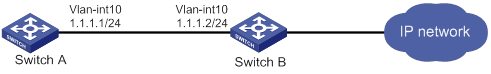
Configuration procedure
1. Configure Switch B:
# Configure ACL 2010 to permit traffic from network 10.1.1.0/24.
<SwitchB> system-view
[SwitchB] acl basic 2010
[SwitchB-acl-ipv4-basic-2010] rule permit source 10.1.1.0 0.0.0.255
[SwitchB-acl-ipv4-basic-2010] quit
# Create VLAN 10.
[SwitchB] vlan 10
[SwitchB-vlan10] quit
# Specify an IP address for VLAN-interface 10.
[SwitchB] interface vlan-interface 10
[SwitchB-Vlan-interface10] ip address 1.1.1.2 255.255.255.0
# Configure strict uRPF check on VLAN-interface 10.
[SwitchB-Vlan-interface10] ip urpf strict acl 2010
2. Configure Switch A:
# Create VLAN 10.
<SwitchA> system view
[SwitchA] vlan 10
[SwitchA-vlan10] quit
# Specify an IP address for VLAN-interface 10.
[SwitchA] interface vlan-interface 10
[SwitchA-Vlan-interface10] ip address 1.1.1.1 255.255.255.0
# Configure strict uRPF check on VLAN-interface 10 and allow using the default route for uRPF check.
[SwitchA-Vlan-interface10] ip urpf strict allow-default-route
Global uRPF configuration example
Network requirements
As shown in Figure 54, a client (Switch A) directly connects to an ISP switch (Switch B).
To prevent source address spoofing attacks, perform the following tasks:
· Enable strict uRPF check on Switch A.
· Enable strict uRPF check on Switch B.
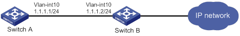
Configuration procedure
1. Enable strict uRPF check on Switch A.
<SwitchA> system-view
[SwitchA] ip urpf strict
2. Enable strict uRPF check on Switch B.
<SwitchB> system-view
[SwitchB] ip urpf strict
Configuring FIPS
Overview
Federal Information Processing Standards (FIPS) was developed by the National Institute of Standards and Technology (NIST) of the United States. FIPS specifies the requirements for cryptographic modules. FIPS 140-2 defines four levels of security, named Level 1 to Level 4, from low to high. The device supports Level 2.
Unless otherwise noted, in this document the term FIPS refers to FIPS 140-2.
Configuration restrictions and guidelines
When you configure FIPS, follow these restrictions and guidelines:
· After the fips mode enable command is executed, the system prompts you to choose a reboot method. If you do not make a choice within 30 seconds, the system uses the manual reboot method.
· Before you reboot the device to enter FIPS mode, the system automatically removes all key pairs configured in non-FIPS mode and all FIPS-incompliant digital certificates. FIPS-incompliant digital certificates are MD5-based certificates with the modulus length of key pairs less than 2048 bits. You cannot log in to the device through SSH after the device enters FIPS mode. To log in to the device in FIPS mode through SSH, first log in to the device through a console port, and then create a key pair for the SSH server.
· The password for entering the device in FIPS mode must comply with the password control policies, such as password length, complexity, and aging policy. When the aging timer for a password expires, the system prompts you to change the password. If you adjust the system time after the device enters FIPS mode, the login password might expire before the next login, because the original system time is typically much earlier than the actual time.
? If you choose the automatic reboot method, set the system time before executing the fips mode enable command.
? If you choose the manual reboot method, set the system time before configuring the local username and password.
· To use the manual reboot method, you must perform the following tasks:
a. Save the current configuration file.
b. Specify the current configuration file as the startup configuration file.
c. Delete the startup configuration file in binary format.
d. Reboot the device.
Otherwise, the commands that are not supported by FIPS mode, if they are in the configuration file, might be restored.
· The system enters an intermediate state between when the fips mode enable command is executed and when the system is rebooted. If you choose the manual reboot method, do not execute any commands except for the following commands:
? reboot.
? save.
? Other commands used for configuration preparation to enter FIPS mode.
· Do not use FIPS and non-FIPS devices to create an IRF fabric.
· To enable FIPS mode for an IRF fabric, you must reboot the entire IRF fabric.
Configuring FIPS mode
Entering FIPS mode
After you enable FIPS mode and reboot the device, the device operates in FIPS mode. The FIPS device has strict security requirements, and performs self-tests on cryptography modules to verify that they are operating correctly.
A FIPS device meets the requirements defined in Network Device Protection Profile (NDPP) of Common Criteria (CC).
The system provides two methods to enter FIPS mode: automatic reboot and manual reboot.
Automatic reboot
To use automatic reboot to enter FIPS mode:
1. Enable FIPS mode.
2. Select the automatic reboot method.
The system automatically performs the following tasks:
a. Create a default FIPS configuration file named fips-startup.cfg.
b. Specify the default file as the startup configuration file.
c. Prompt you to configure the username and password for next login.
You can press Ctrl+C to exit the configuring process. The fips mode enable command will not be executed.
3. Configure a username and password to log in to the device in FIPS mode.
The password must include at least 15 characters that contain uppercase and lowercase letters, digits, and special characters.
The system automatically uses the startup configuration file to reboot the device and enter FIPS mode. You can only use the configured username and password to log in to the FIPS device. After login, you are assigned the role of security administrator Crypto Officer.
Manual reboot
To use manual reboot to enter FIPS mode:
1. Enable the password control feature globally.
3. Set the minimum length of user passwords to 15 characters.
4. Add a local user account for device management, including the following items:
? A username.
? A password that complies with the password control policies as described in step 2 and step 3.
? A user role of network-admin.
? A service type of terminal.
5. Delete the FIPS-incompliant local user service types Telnet, HTTP, and FTP.
6. Enable FIPS mode.
7. Select the manual reboot method.
8. Save the configuration file and specify it as the startup configuration file.
9. Delete the startup configuration file in binary format (an .mdb file).
10. Reboot the device.
The system enters FIPS mode. You can use the configured username and password to log in to the device in FIPS mode.
To enable FIPS mode:
|
Step |
Command |
Remarks |
|
1. Enter system view. |
system-view |
N/A |
|
2. Enable FIPS mode. |
fips mode enable |
By default, the FIPS mode is disabled. |
Configuration changes in FIPS mode
When the system enters FIPS mode, the following system changes occur:
· The user login authentication mode can only be scheme.
· The FTP/TFTP server and client are disabled.
· The Telnet server and client are disabled.
· The HTTP server is disabled.
· SNMPv1 and SNMPv2c are disabled. Only SNMPv3 is available.
· The SSH server does not support SSHv1 clients and DSA key pairs.
· The generated RSA and DSA key pairs must have a modulus length of 2048 bits.
When the device acts as a server to authenticate a client through the public key, the key pair for the client must also have a modulus length of 2048 bits.
· The generated ECDSA key pairs must have a modulus length of more than 256 bits.
When the device acts as a server to authenticate a client through the public key, the key pair for the client must also have a modulus length of more than 256 bits.
· SSH and SNMPv3 do not support DES, 3DES, RC4, or MD5.
· The password control feature cannot be disabled globally. The undo password-control enable command does not take effect.
· The keys must contain at least 15 characters and 4 character types of uppercase and lowercase letters, digits, and special characters. This requirement applies to the following passwords:
? AAA server's shared key.
? SNMPv3 authentication key.
The password for a device management local user and password for switching user roles depend on password control policies. By default, the passwords must contain at least 15 characters and 4 character types of uppercase and lowercase letters, digits, and special characters.
Exiting FIPS mode
After you disable FIPS mode and reboot the device, the device operates in non-FIPS mode.
The system provides two methods to exit FIPS mode: automatic reboot and manual reboot.
Automatic reboot
Select the automatic reboot method. The system automatically creates a default non-FIPS configuration file named non-fips-startup.cfg, and specifies the file as the startup configuration file. The system reboots the device by using the default non-FIPS configuration file. After the reboot, you are directly logged in to the device.
Manual reboot
This method requires that you manually complete the configurations for entering non-FIPS mode, and then reboot the device. To log in to the device after the reboot, you must enter user information according to the authentication mode. The following default authentication modes are available for console ports or lines (you can modify the default mode as needed):
· The default authentication mode is password for VTY lines.
· The default authentication mode is none for console ports.
After you disable FIPS mode, follow these restrictions and guidelines before you manually reboot the device:
· If you are logged in to the device through Telnet, perform the following tasks without exiting the current user line:
? Set the authentication mode to scheme.
? Configure the username and password. (You can also use the current username and password.)
· If you are logged in to the device through a console port, configure one of the following authentication modes as needed:
? Configure the password authentication mode and a password.
? Configure the scheme authentication mode and configure a new username and password (you can also use the current username and password).
? Configure the none authentication mode.
To disable FIPS mode:
|
Step |
Command |
Remarks |
|
1. Enter system view. |
system-view |
N/A |
|
2. Disable FIPS mode. |
undo fips mode enable |
By default, the FIPS mode is disabled. |
FIPS self-tests
To ensure the correct operation of cryptography modules, FIPS provides self-test mechanisms, including power-up self-test and conditional self-test. You can also trigger a self-test. If the power-up self-test fails, the card where the self-test process exists reboots. If the conditional self-test fails, the system outputs self-test failure information.
|
|
NOTE: If a self-test fails, contact H3C Support. |
Power-up self-tests
The power-up self-test examines the availability of FIPS-allowed cryptographic algorithms.
The device supports the following types of power-up self-tests:
· Known-answer test (KAT)
A cryptographic algorithm is run on data for which the correct output is already known. The calculated output is compared with the known answer. If they are not identical, the KAT test fails.
· Pairwise conditional test (PWCT)
? Signature and authentication test—The test is run when a DSA, RSA, or ECDSA asymmetrical key pair is generated. It uses the private key to sign the specific data, and then uses the public key to authenticate the signed data. If the authentication is successful, the test succeeds.
? Encryption and decryption test—The test is run when an RSA asymmetrical key pair is generated. It uses the public key to encrypt a plain text string, and then uses the private key to decrypt the encrypted text. If the decryption result is the same as the original plain text string, the test succeeds.
The power-up self-test examines the cryptographic algorithms listed in Table 11.
Table 11 Power-up self-test list
|
Type |
Operations |
|
KAT |
Tests the following algorithms: · SHA1, SHA224, SHA256, SHA384, and SHA512. · HMAC-SHA1, HMAC-SHA224, HMAC-SHA256, HMAC-SHA384, and HMAC-SHA512. · AES. · RSA (signature and authentication). · ECDH. · DRBG. · GCM. · GMAC. |
|
PWCT |
Tests the following algorithms: · RSA (signature and authentication). · RSA (encryption and decryption). · DSA (signature and authentication). · ECDSA (signature and authentication). |
Conditional self-tests
A conditional self-test runs when an asymmetrical cryptographic module or a random number generator module is invoked. Conditional self-tests include the following types:
· PWCT signature and authentication—This test is run when a DSA or RSA asymmetrical key pair is generated. It uses the private key to sign the specific data, and then uses the public key to authenticate the signed data. If the authentication is successful, the test succeeds.
Triggering self-tests
To examine whether the cryptography modules operate correctly, you can trigger a self-test on the cryptographic algorithms. The triggered self-test is the same as the power-up self-test. If the self-test fails, the card where the self-test process exists reboots.
To trigger a self-test:
|
Step |
Command |
|
1. Enter system view. |
system-view |
|
2. Trigger a self-test. |
fips self-test |
Displaying and maintaining FIPS
Execute display commands in any view.
|
Task |
Command |
|
Display the FIPS mode state. |
display fips status |
FIPS configuration examples
Entering FIPS mode through automatic reboot
Network requirements
Use the automatic reboot method to enter FIPS mode, and use a console port to log in to the device in FIPS mode.
Configuration procedure
# Enable FIPS mode and choose the automatic reboot method to enter FIPS mode. Set the username to root and the password to 12345zxcvb!@#$%ZXCVB.
<Sysname> system-view
[Sysname] fips mode enable
FIPS mode change requires a device reboot. Continue? [Y/N]:y
Reboot the device automatically? [Y/N]:y
The system will create a new startup configuration file for FIPS mode. After you set the login username and password for FIPS mode, the device will reboot automatically.
Enter username(1-55 characters):root
Enter password(15-63 characters):
Confirm password:
Waiting for reboot... After reboot, the device will enter FIPS mode.
Verifying the configuration
After the device reboots, enter a username of root and a password of 12345zxcvb!@#$%ZXCVB. The system prompts you to configure a new password. After you configure the new password, the device enters FIPS mode. The new password must be different from the previous password. It must include at least 15 characters, and contain uppercase and lowercase letters, digits, and special characters. For more information about the requirements for the password, see the system output.
Press ENTER to get started.
login: root
Password:
First login or password reset. For security reason, you need to change your password. Please enter your password.
old password:
new password:
confirm:
Updating user information. Please wait ... ...
…
<Sysname>
# Display the FIPS mode state.
<Sysname> display fips status
FIPS mode is enabled.
# Display the default configuration file.
<Sysname> more fips-startup.cfg
#
password-control enable
#
local-user root class manage
service-type terminal
authorization-attribute user-role network-admin
#
fips mode enable
#
return
<Sysname>
Entering FIPS mode through manual reboot
Network requirements
Use the manual reboot method to enter FIPS mode, and use a console port to log in to the device in FIPS mode.
Configuration procedure
# Enable the password control feature globally.
<Sysname> system-view
[Sysname] password-control enable
# Set the number of character types a password must contain to 4, and set the minimum number of characters for each type to one character.
[Sysname] password-control composition type-number 4 type-length 1
# Set the minimum length of user passwords to 15 characters.
[Sysname] password-control length 15
# Add a local user account for device management, including a username of test, a password of 12345zxcvb!@#$%ZXCVB, a user role of network-admin, and a service type of terminal.
[Sysname] local-user test class manage
[Sysname-luser-manage-test] password simple 12345zxcvb!@#$%ZXCVB
[Sysname-luser-manage-test] authorization-attribute user-role network-admin
[Sysname-luser-manage-test] service-type terminal
[Sysname-luser-manage-test] quit
# Enable FIPS mode, and choose the manual reboot method to enter FIPS mode.
[Sysname] fips mode enable
FIPS mode change requires a device reboot. Continue? [Y/N]:y
Reboot the device automatically? [Y/N]:n
Change the configuration to meet FIPS mode requirements, save the configuration to the next-startup configuration file, and then reboot to enter FIPS mode.
# Save the current configuration to the root directory of the storage medium, and specify it as the startup configuration file.
[Sysname] save
The current configuration will be written to the device. Are you sure? [Y/N]:y
Please input the file name(*.cfg)[flash:/startup.cfg]
(To leave the existing filename unchanged, press the enter key):
flash:/startup.cfg exists, overwrite? [Y/N]:y
Validating file. Please wait...
Saved the current configuration to mainboard device successfully.
Slot 1:
Save next configuration file successfully.
[Sysname] quit
# Delete the startup configuration file in binary format.
<Sysname> delete flash:/startup.mdb
Delete flash:/startup.mdb?[Y/N]:y
Deleting file flash:/startup.mdb...Done.
# Reboot the device.
<Sysname> reboot
Verifying the configuration
Press ENTER to get started.
login: test
Password:
First login or password reset. For security reason, you need to change your pass
word. Please enter your password.
old password:
new password:
confirm:
Updating user information. Please wait ... ...
…
<Sysname>
# Display the FIPS mode state.
<Sysname> display fips status
FIPS mode is enabled.
Exiting FIPS mode through automatic reboot
Network requirements
A user has logged in to the device in FIPS mode through a console port.
Use the automatic reboot method to exit FIPS mode.
Configuration procedure
# Disable FIPS mode.
[Sysname] undo fips mode enable
FIPS mode change requires a device reboot. Continue? [Y/N]:y
The system will create a new startup configuration file for non-FIPS mode and then reboot automatically. Continue? [Y/N]:y
Waiting for reboot... After reboot, the device will enter non-FIPS mode.
Verifying the configuration
After the device reboots, you can enter the system.
<Sysname>
# Display the FIPS mode state.
<Sysname> display fips status
FIPS mode is disabled.
Exiting FIPS mode through manual reboot
Network requirements
A user has logged in to the device in FIPS mode through SSH with a username of test and a password of 12345zxcvb!@#$%ZXCVB.
Use the manual reboot method to exit FIPS mode.
Configuration procedure
# Disable FIPS mode.
[Sysname] undo fips mode enable
FIPS mode change requires a device reboot. Continue? [Y/N]:y
The system will create a new startup configuration file for non-FIPS mode, and then reboot automatically. Continue? [Y/N]:n
Change the configuration to meet non-FIPS mode requirements, save the configuration to the next-startup configuration file, and then reboot to enter non-FIPS mode.
# Set the authentication mode for VTY lines to scheme.
[Sysname] line vty 0 63
[Sysname-line-vty0-63] authentication-mode scheme
# Save the current configuration to the root directory of the storage medium, and specify it as the startup configuration file.
[Sysname] save
The current configuration will be written to the device. Are you sure? [Y/N]:y
Please input the file name(*.cfg)[flash:/startup.cfg]
(To leave the existing filename unchanged, press the enter key):
flash:/startup.cfg exists, overwrite? [Y/N]:y
Validating file. Please wait...
Saved the current configuration to mainboard device successfully.
Slot 1:
Save next configuration file successfully.
[Sysname] quit
# Delete the startup configuration file in binary format.
<Sysname> delete flash:/startup.mdb
Delete flash:/startup.mdb?[Y/N]:y
Deleting file flash:/startup.mdb...Done.
# Reboot the device.
<Sysname> reboot
Verifying the configuration
After the device reboots, enter a username of test and a password of 12345zxcvb!@#$%ZXCVB to enter non-FIPS mode.
Press ENTER to get started.
login: test
Password:
Last successfully login time:…
…
<Sysname>
# Display the FIPS mode state.
<Sysname> display fips status
FIPS mode is disabled.
A
concurrent login user max, 46
configuration, 1, 16, 47
device ID configuration, 47
device implementation, 9
display, 47
displaying local users/user groups, 20
FIPS compliance, 16
HWTACACS accounting server, 34
HWTACACS authentication server, 33
HWTACACS authorization server, 33
HWTACACS display, 38
HWTACACS implementation, 6
HWTACACS maintain, 38
HWTACACS outgoing packet source IP address, 36
HWTACACS scheme, 32
HWTACACS scheme creation, 32
HWTACACS scheme VPN instance, 35
HWTACACS server SSH user, 47
HWTACACS shared keys, 35
HWTACACS timer set, 37
HWTACACS traffic statistics units, 35
HWTACACS username format, 35
HWTACACS/RADIUS differences, 7
ISP domain accounting method, 42
ISP domain attribute configuration, 39
ISP domain authentication method, 40
ISP domain authorization method, 41
ISP domain creation, 38
ISP domain method, 38
local user attribute, 18
local user configuration, 17
methods, 9
MPLS L3VPN implementation, 11
NAS-ID profile configuration, 46
protocols and standards, 11
RADIUS accounting server parameters, 23
RADIUS accounting-on configuration, 29
RADIUS attribute translation, 45
RADIUS attributes, 11
RADIUS authentication server, 22
RADIUS DAS, 44
RADIUS display, 32
RADIUS implementation, 2
RADIUS maintain, 32
RADIUS packet DSCP priority, 44
RADIUS request transmission attempts max, 25
RADIUS scheme, 20
RADIUS scheme creation, 22
RADIUS scheme VPN instance, 24
RADIUS server SSH user authentication+authorization, 50
RADIUS server status, 26
RADIUS session-control, 43
RADIUS shared keys, 24
RADIUS SNMP notification, 31
RADIUS timer set, 28
RADIUS traffic statistics units, 25
RADIUS username format, 25
scheme configuration, 17
SSH user local authentication+HWTACACS authorization+RADIUS accounting, 49
troubleshoot HWTACACS, 55
troubleshoot RADIUS, 54
troubleshoot RADIUS accounting error, 55
troubleshoot RADIUS authentication failure, 54
troubleshoot RADIUS packet delivery failure, 54
user group attribute, 19
user management by ISP domains, 9
user management by user access types, 9
account idle time (password control), 59
accounting
AAA configuration, 1, 16, 47
AAA device ID configuration, 47
AAA ISP domain accounting method, 42
AAA RADIUS accounting server parameters, 23
AAA RADIUS accounting-on, 29
AAA SSH user local authentication+HWTACACS authorization+RADIUS accounting, 49
ACK flood attack, 136
ACL
attack D&P detection exemption, 139
SSH management parameters, 90
active
ARP active acknowledgement, 165
address
global uRPF configuration, 186
uRPF configuration, 181, 185
uRPF configuration (interface), 185
uRPF enable, 184
Address Resolution Protocol. Use ARP
algorithm
keychain configuration, 67
keychain configuration (on switch), 68
SSH negotiation, 84
SSH2, 102
SSH2 encryption, 103
SSH2 key exchange, 103
SSH2 MAC, 104
SSH2 public key, 103
any authentication (SSH), 84
application
uRPF network, 184
applying
attack D&P policy application (device), 140, 140
attack protection. See ARP attack protection
scanning configuration restrictions, 175
active acknowledgement, 165
ARP attack detection display, 171
ARP attack detection maintain, 171
authorized ARP configuration, 165
authorized ARP configuration (DHCP relay agent), 167
authorized ARP configuration (DHCP server), 166
configuration, 159
configuration (user+packet validity check), 171
detection configuration, 168
filtering configuration, 176, 177
fixed ARP configuration, 174
gateway protection, 175, 176
logging enable, 171
packet rate limit configuration, 161
packet source MAC consistency check, 165
packet validity check configuration, 169
restricted forwarding, 170
restricted forwarding configuration, 173
scanning configuration, 174
source MAC-based attack detection, 162, 164
source MAC-based detection display, 163
unresolvable IP attack, 159, 161
unresolvable IP attack blackhole routing, 160
unresolvable IP attack protection display, 160
unresolvable IP attack source suppression, 160
user validity check, 169
attack
ARP attack protection configuration, 159
TCP attack prevention configuration, 147
configuration, 129, 132, 143
configuration (device application), 143
defense policy configuration, 133
defense policy configuration (ACK flood attack), 136
defense policy configuration (DNS flood attack), 139
defense policy configuration (FIN flood attack), 137
defense policy configuration (flood attack), 135
defense policy configuration (HTTP flood attack), 139
defense policy configuration (ICMP flood attack), 137
defense policy configuration (ICMPv6 flood attack), 138
defense policy configuration (RST flood attack), 137
defense policy configuration (scanning attack), 135
defense policy configuration (single-packet attack), 133
defense policy configuration (SYN flood attack), 135
defense policy configuration (SYN-ACK flood attack), 136
defense policy configuration (UDP flood attack), 138
defense policy creation, 133
detection exemption configuration, 139
device-preventable attacks, 129
display, 141
flood attack, 131
log non-aggregation enable, 140
login delay, 141
login dictionary attack, 132
maintain, 141
policy application (device), 140
scanning attack, 130
single-packet attack, 129
TCP fragment attack, 132
TCP fragment attack prevention configuration, 141
attack detection and prevention. See attack D&P
attacking
detection and prevention. See attack D&P
attribute
AAA HWTACACS scheme, 32
AAA ISP domain attribute, 39
AAA local user, 17
AAA local user attribute, 18
AAA proprietary RADIUS subattributes (vendor ID 25506), 13
AAA RADIUS, 11
AAA RADIUS attribute 31 MAC address format, 30
AAA RADIUS attribute translation, 45
AAA RADIUS common standard attributes, 11
AAA RADIUS extended attributes, 6
AAA RADIUS Login-Service attribute check method, 30
AAA RADIUS Remanent_Volume attribute data measurement unit, 31
AAA RADIUS scheme, 20
AAA scheme, 17
AAA user group attribute, 19
authenticating
AAA configuration, 1, 16, 47
AAA ISP domain authentication method, 40
AAA RADIUS server SSH user authentication+authorization, 50
AAA RADIUS user authentication methods, 2
AAA SSH user local authentication+HWTACACS authorization+RADIUS accounting, 49
keychain configuration, 67
keychain configuration (on switch), 68
password control configuration, 56, 59, 64
SSH configuration, 83
SSH methods, 84
SSH SCP file transfer+password authentication, 124
SSH Secure Telnet client configuration (password authentication-enabled), 113
SSH Secure Telnet client configuration (publickey authentication-enabled), 116
SSH Secure Telnet server configuration (password authentication-enabled), 105
SSH Secure Telnet server configuration (publickey authentication-enabled), 107
SSH server configuration, 85
SSH SFTP client configuration (publickey authentication-enabled), 121
SSH SFTP server configuration (password authentication-enabled), 119
Authentication, Authorization, and Accounting. Use AAA
authorized ARP
configuration, 165
configuration configuration (DHCP relay agent), 167
configuration configuration (DHCP server), 166
authorizing
AAA configuration, 1, 16, 47
AAA ISP domain authorization method, 41
AAA RADIUS server SSH user authentication+authorization, 50
AAA RADIUS session-control, 43
AAA SSH user local authentication+HWTACACS authorization+RADIUS accounting, 49
auto
FIPS mode (automatic reboot), 189
FIPS mode entry (automatic reboot), 193
FIPS mode exit (automatic reboot), 190, 195
B
binding
IP source guard (IPSG) dynamic binding, 149
IP source guard (IPSG) static binding, 148
IPv4 source guard (IPv4SG) static binding configuration, 150
IPv6 source guard (IPv6SG) static binding configuration, 152
blackhole
ARP attack protection blackhole routing (unresolvable IP attack), 160
C
CAR
AAA RADIUS class attribute as CAR parameter, 30
changing
AAA RADIUS packet DSCP priority, 44
checking
uRPF loose check mode, 181
uRPF strict check mode, 181
class
AAA RADIUS class attribute as CAR parameter, 30
command
AAA command accounting method, 9
AAA command authorization method, 9
complexity checking (password control), 57
composition checking (password control), 56
conditional self-test, 192
configuring
AAA, 1, 16, 47
AAA device ID, 47
AAA HWTACACS schemes, 32
AAA HWTACACS server SSH user, 47
AAA ISP domain accounting method, 42
AAA ISP domain attribute, 39
AAA ISP domain authentication method, 40
AAA ISP domain authorization method, 41
AAA ISP domain method, 38
AAA local user, 17
AAA local user attributes, 18
AAA NAS-ID profile, 46
AAA RADIUS accounting-on, 29
AAA RADIUS attribute 31 MAC address format, 30
AAA RADIUS attribute translation, 45
AAA RADIUS DAS, 44
AAA RADIUS Login-Service attribute check method, 30
AAA RADIUS scheme, 20
AAA RADIUS server SSH user authentication+authorization, 50
AAA RADIUS server status detection test profile, 21
AAA RADIUS session-control, 43
AAA scheme, 17
AAA SSH user local authentication+HWTACACS authorization+RADIUS accounting, 49
AAA user group attributes, 19
ARP active acknowledgement, 165
ARP attack detection, 168
ARP attack detection (source MAC-based), 162, 164
ARP attack detection (user+packet validity check), 171
ARP attack detection packet validity check, 169
ARP attack detection restricted forwarding, 170, 173
ARP attack detection user validity check, 169
ARP attack protection, 159
ARP attack protection (unresolvable IP attack), 159, 161
ARP attack protection blackhole routing (unresolvable IP attack), 160
ARP attack protection source suppression (unresolvable IP attack), 160
ARP filtering, 176, 177
ARP gateway protection, 175, 176
ARP packet rate limit, 161
ARP packet source MAC consistency check, 165
ARP scanning, 174
attack D&P, 129, 132, 143
attack D&P (device application), 143
attack D&P defense policy, 133
attack D&P defense policy (ACK flood attack), 136
attack D&P defense policy (DNS flood attack), 139
attack D&P defense policy (FIN flood attack), 137
attack D&P defense policy (flood attack), 135
attack D&P defense policy (HTTP flood attack), 139
attack D&P defense policy (ICMP flood attack), 137
attack D&P defense policy (ICMPv6 flood attack), 138
attack D&P defense policy (RST flood attack), 137
attack D&P defense policy (scanning attack), 135
attack D&P defense policy (single-packet attack), 133
attack D&P defense policy (SYN flood attack), 135
attack D&P defense policy (SYN-ACK flood attack), 136
attack D&P defense policy (UDP flood attack), 138
attack D&P detection exemption, 139
attack D&P TCP fragment attack prevention, 141
authorized ARP, 165
authorized ARP (DHCP relay agent), 167
authorized ARP (DHCP server), 166
dynamic IPv4 source guard (IPv4SG)+DHCP relay agent, 155
dynamic IPv4 source guard (IPv4SG)+DHCP snooping, 154
dynamic IPv6 source guard (IPv6SG)+DHCPv6 relay agent, 157
FIPS, 188, 193
FIPS mode, 189
fixed ARP, 174
global uRPF, 186
IP source guard (IPSG), 148, 149, 153
IPv4 source guard (IPv4SG), 150
IPv4 source guard (IPv4SG) static binding, 150
IPv6 source guard (IPv6SG), 151
IPv6 source guard (IPv6SG) static binding, 152
keychain, 67
keychain (on switch), 68
ND attack defense, 179
NETCONF-over-SSH client user line, 88
NETCONF-over-SSH+password authentication, 126
password control, 56, 59, 64
peer host public key, 77
Secure Telnet client user line, 88
source MAC consistency check, 179
SSH, 83
SSH client host public key, 88
SSH device as Secure Telnet client, 92
SSH device as server, 85
SSH device as SFTP client, 95
SSH management parameters, 90
SSH SCP client device, 100
SSH SCP file+password authentication, 124
SSH Secure Telnet, 104
SSH Secure Telnet client (password authentication-enabled), 113
SSH Secure Telnet client (publickey authentication-enabled), 116
SSH Secure Telnet server (password authentication-enabled), 105
SSH Secure Telnet server (publickey authentication-enabled), 107
SSH SFTP, 118
SSH SFTP client (publickey authentication-enabled), 121
SSH SFTP server (password authentication-enabled), 119
SSH user, 89
SSH2 algorithms (encryption ), 103
SSH2 algorithms (key exchange), 103
SSH2 algorithms (MAC), 104
SSH2 algorithms (public key), 103
static IPv4 source guard (IPv4SG), 153
static IPv6 source guard (IPv6SG), 156
TCP attack prevention, 147
TCP Naptha attack prevention, 147
uRPF, 181, 185
uRPF (interface), 185
consistency check (ARP attack protection), 165
controlling
AAA RADIUS session-control, 43
creating
AAA HWTACACS scheme, 32
AAA ISP domain, 38
AAA RADIUS scheme, 22
attack D&P defense policy, 133
local key pair, 74
cryptography
FIPS self-test, 191
D
DAE
AAA RADIUS DAS, 44
defending
attack D&P defense policy, 133
attack D&P defense policy (flood attack), 135
attack D&P defense policy (ICMP flood attack), 137
attack D&P defense policy (ICMPv6 flood attack), 138
attack D&P defense policy (scanning attack), 135
attack D&P defense policy (single-packet attack), 133
attack D&P defense policy (UDP flood attack), 138
attack D&P defense policy configuration (ACK flood attack), 136
attack D&P defense policy configuration (DNS flood attack), 139
attack D&P defense policy configuration (FIN flood attack), 137
attack D&P defense policy configuration (HTTP flood attack), 139
attack D&P defense policy configuration (RST flood attack), 137
attack D&P defense policy configuration (SYN flood attack), 135
attack D&P defense policy configuration (SYN-ACK flood attack), 136
attack D&P policy application (device), 140
destroying
local key pair, 77
detecting
AAA RADIUS server status detection test profile, 21
ARP attack detection (source MAC-based), 162, 164
ARP attack detection configuration, 168
attack D&P detection exemption, 139
device
AAA configuration, 1, 16, 47
AAA device ID configuration, 47
AAA device management user, 17
AAA HWTACACS accounting server, 34
AAA HWTACACS authentication server, 33
AAA HWTACACS authorization server, 33
AAA HWTACACS implementation, 6
AAA HWTACACS scheme, 32
AAA HWTACACS scheme VPN instance, 35
AAA HWTACACS server SSH user, 47
AAA HWTACACS shared keys, 35
AAA implementation, 9
AAA local user, 17
AAA MPLS L3VPN implementation, 11
AAA RADIUS accounting server parameters, 23
AAA RADIUS authentication server, 22
AAA RADIUS implementation, 2
AAA RADIUS scheme, 20
AAA RADIUS scheme VPN instance, 24
AAA RADIUS server SSH user authentication+authorization, 50
AAA RADIUS server status, 26
AAA RADIUS shared keys, 24
AAA scheme, 17
AAA SSH user local authentication+HWTACACS authorization+RADIUS accounting, 49
attack D&P configuration, 129, 132, 143
attack D&P configuration (device application), 143
attack D&P defense policy, 133
attack D&P device-preventable attacks, 129
attack D&P policy application (device), 140
authorized ARP configuration (DHCP server), 166
global uRPF configuration, 186
keychain configuration (on switch), 68
NETCONF-over-SSH+password authentication configuration, 126
password control configuration, 56, 59, 64
password control parameters (global), 60
password control parameters (local user), 62
password control parameters (super), 63
password control parameters (user group), 61
password setting, 56
SSH SCP client, 100
SSH SCP file transfer+password authentication, 124
SSH SCP server enable, 87
SSH Secure Telnet client, 92
SSH Secure Telnet client configuration (password authentication-enabled), 113
SSH Secure Telnet client configuration (publickey authentication-enabled), 116
SSH Secure Telnet configuration, 104
SSH Secure Telnet server configuration (password authentication-enabled), 105
SSH Secure Telnet server configuration (publickey authentication-enabled), 107
SSH Secure Telnet server connection establishment, 93
SSH Secure Telnet server enable, 87
SSH server configuration, 85
SSH SFTP client, 95
SSH SFTP client configuration (publickey authentication-enabled), 121
SSH SFTP configuration, 118
SSH SFTP server configuration (password authentication-enabled), 119
SSH SFTP server enable, 87
uRPF configuration, 185
uRPF configuration (interface), 185
DHCP
dynamic IPv4 source guard (IPv4SG)+DHCP relay agent configuration, 155
dynamic IPv4 source guard (IPv4SG)+DHCP snooping configuration, 154
dynamic IPv6 source guard (IPv6SG)+DHCPv6 relay agent configuration, 157
dictionary
attack D&P login delay, 141
attack D&P login dictionary attack, 132
Digital Signature Algorithm. Use DSA
directory
SSH SFTP, 98
displaying
AAA, 47
AAA HWTACACS, 38
AAA local users/user groups, 20
AAA RADIUS, 32
ARP attack detection, 171
ARP attack detection (source MAC-based), 163
ARP attack protection (unresolvable IP attack), 160
attack D&P, 141
FIPS, 193
host public key, 76
IP source guard (IPSG), 152
IPv4 source guard (IPv4SG), 152
IPv6 source guard (IPv6SG), 152
keychain, 68
password control, 64
public key, 78
SSH, 104
SSH SFTP help information, 99
uRPF, 185
distributing
local host public key, 76
DNS
attack D&P defense policy (DNS flood attack), 139
domain
AAA ISP domain accounting method, 42
AAA ISP domain attribute, 39
AAA ISP domain authentication method, 40
AAA ISP domain authorization method, 41
host public key display, 76
host public key export, 76
peer host public key entry, 78
public key import from file, 80
public key management, 74, 78
SSH client host public key configuration, 88
SSH Secure Telnet client configuration (publickey authentication-enabled), 116
DSCP
AAA RADIUS packet DSCP priority change, 44
dst-mac validity check (ARP attack detection), 169
dynamic
IP source guard (IPSG) dynamic binding, 149
IPv4 source guard (IPv4SG)+DHCP relay agent configuration, 155
IPv4 source guard (IPv4SG)+DHCP snooping configuration, 154
IPv6 source guard (IPv6SG)+DHCPv6 relay agent configuration, 157
E
peer host public key entry, 78
public key import from file, 80
public key management, 74, 78
Elliptic Curve Digital Signature Algorithm. Use ECDSA
enabling
AAA RADIUS server load sharing, 27
AAA RADIUS SNMP notification, 31
ARP attack detection logging, 171
attack D&P log non-aggregation, 140
attack D&P login delay, 141
IPv4 source guard (IPv4SG) on interface, 150
IPv6 source guard (IPv6SG) on interface, 151
NETCONF-over-SSH, 87
password control, 60
SSH SCP server, 87
SSH Secure Telnet server, 87
SSH SFTP server, 87
uRPF, 184
encrypting
public key management, 74, 78
SSH configuration, 83
SSH server configuration, 85
entering
FIPS mode (automatic reboot), 189, 193
FIPS mode (manual reboot), 189, 194
peer host public key, 78, 78
SSH client host public key, 88
establishing
SSH SCP server connection, 100
SSH Secure Telnet server connection, 93
SSH SFTP server connection, 97
Ethernet
ARP attack protection configuration, 159
exempting
attack D&P detection exemption, 139
exiting
FIPS mode (automatic reboot), 190, 195
FIPS mode (manual reboot), 190, 196
exporting
host public key, 76
F
Federal Information Processing Standard. Use FIPS
file
SSH SCP file transfer+password authentication, 124
SSH SFTP, 99
filtering
ARP packet filtering configuration, 176, 177
FIN flood attack, 137
configuration, 188, 193
configuration restrictions, 188
display, 193
mode configuration, 189
mode entry, 189
mode entry (automatic reboot), 193
mode entry (manual reboot), 194
mode exit, 190
mode exit (automatic reboot), 195
mode exit (manual reboot), 196
mode system changes, 190
self-test, 191
self-test trigger, 192
FIPS compliance
AAA, 16
password control, 59
public key, 74
SSH, 85
fixed ARP
configuration, 174
configuration restrictions, 175
flood attack
attack D&P defense policy, 135
attack D&P defense policy (ACK flood attack), 136
attack D&P defense policy (DNS flood attack), 139
attack D&P defense policy (FIN flood attack), 137
attack D&P defense policy (HTTP flood attack), 139
attack D&P defense policy (ICMP flood attack), 137
attack D&P defense policy (ICMPv6 flood attack), 138
attack D&P defense policy (RST flood attack), 137
attack D&P defense policy (SYN flood attack), 135
attack D&P defense policy (SYN-ACK flood attack), 136
attack D&P defense policy (UDP flood attack), 138
attack D&P device-preventable attacks, 131
format
AAA HWTACACS username, 35
AAA RADIUS attribute 31 MAC address format, 30
AAA RADIUS packet format, 3
AAA RADIUS username, 25
forwarding
ARP attack detection restricted forwarding, 170
ARP attack detection restricted forwarding configuration, 173
dynamic IPv4 source guard (IPv4SG)+DHCP relay agent configuration, 155
dynamic IPv4 source guard (IPv4SG)+DHCP snooping configuration, 154
dynamic IPv6 source guard (IPv6SG)+DHCPv6 relay agent configuration, 157
IP source guard (IPSG) configuration, 148, 149, 153
ND attack defense configuration, 179
static IPv4 source guard (IPv4SG) configuration, 153
static IPv6 source guard (IPv6SG) configuration, 156
fragment
attack D&P TCP fragment attack prevention, 141
FTP
AAA RADIUS Login-Service attribute check method, 30
local host public key distribution, 76
SSH SCP server connection establishment, 100
SSH SFTP client configuration (publickey authentication-enabled), 121
SSH SFTP client device, 95
SSH SFTP configuration, 118
SSH SFTP directories, 98
SSH SFTP files, 99
SSH SFTP packet source IP address, 96
SSH SFTP server configuration (password authentication-enabled), 119
SSH SFTP server connection establishment, 97
SSH SFTP server connection termination, 99
G
gateway
ARP gateway protection, 175, 176
generating
Secure Telnet client local key pair, 92
SSH SCP client local key pair, 100
SSH server local key pair, 86
SSH SFTP client local key pair, 96
H
history
password history, 58
host
local host public key distribution, 76
peer host public key configuration, 77
peer host public key entry, 78, 78
peer host public key import from file, 77
public key display, 76
public key export, 76
SSH client host public key configuration, 88
HTTP
attack D&P defense policy (HTTP flood attack), 139
HW Terminal Access Controller Access Control System. Use HWTACACS
AAA configuration, 1, 16, 47
AAA for SSH user, 47
AAA implementation, 6
AAA local user configuration, 17
AAA MPLS L3VPN implementation, 11
AAA scheme, 17
accounting server, 34
authentication server, 33
authorization server, 33
display, 38
HWTACACS/RADIUS differences, 7
maintain, 38
outgoing packet source IP address, 36
packet exchange process, 7
protocols and standards, 11
scheme configuration, 32
scheme creation, 32
scheme VPN instance, 35
shared keys, 35
SSH user local authentication+HWTACACS authorization+RADIUS accounting, 49
timer set), 37
traffic statistics units, 35
troubleshooting, 55
username format, 35
I
ICMP
attack D&P defense policy (ICMP flood attack), 137
attack D&P defense policy (ICMPv6 flood attack), 138
ID
AAA device ID configuration, 47
IMC
AAA RADIUS session-control, 43
implementing
AAA for MPLS L3VPNs, 11
AAA HWTACACS, 6
AAA on device, 9
AAA RADIUS, 2
importing
peer host public key from file, 77
public key from file, 80
SSH client host public key, 89
interpreting
AAA RADIUS class attribute as CAR parameter, 30
IP
global uRPF configuration, 186
uRPF configuration, 185
uRPF configuration (interface), 185
uRPF enable, 184
IP addressing
AAA HWTACACS outgoing packet source IP address, 36
AAA RADIUS outgoing packet source IP address, 27
ARP attack detection configuration (user+packet validity check), 171
ARP attack detection ip validity check, 169
ARP attack detection restricted forwarding configuration, 173
ARP attack protection (unresolvable IP attack), 159, 161
ARP attack protection configuration, 159
ARP filtering configuration, 177
ARP gateway protection, 176
authorized ARP configuration (DHCP relay agent), 167
authorized ARP configuration (DHCP server), 166
SSH Secure Telnet packet source IP address, 92
SSH SFTP packet source IP address, 96
uRPF configuration, 181
IP source guard
IPv4. See IPv4 source guard
IPv6. See IPv6 source guard
IP source guard (IPSG)
configuration, 148, 149, 153
display, 152
dynamic binding, 149
maintain, 152
static binding, 148
IPv4
source guard. See IPv4 source guard
SSH SCP client device, 100
SSH SCP server connection establishment, 100
SSH Secure Telnet server connection establishment, 93
SSH SFTP server connection establishment, 97
IPv4 source guard (IPv4SG)
configuration, 148, 149, 150, 153
display, 152
dynamic configuration+DHCP relay agent, 155
dynamic configuration+DHCP snooping, 154
enable on interface, 150
maintain, 152
static binding configuration, 150
static configuration, 153
IPv6
ND attack defense. See IPv6 ND attack defense
source guard. See IPv6 source guard
SSH SCP client device, 100
SSH SCP server connection establishment, 100
SSH Secure Telnet server connection establishment, 93
SSH SFTP server connection establishment, 97
IPv6 source guard (IPv6SG)
configuration, 148, 149, 151, 153
display, 152
dynamic configuration+DHCPv6 relay agent, 157
enable on interface, 151
maintain, 152
static binding configuration, 152
static configuration, 156
ISP
AAA device implementation, 9
AAA ISP domain accounting method, 42
AAA ISP domain attribute, 39
AAA ISP domain authentication method, 40
AAA ISP domain authorization method, 41
AAA ISP domain creation, 38
AAA ISP domain method, 38
K
key pair
Secure Telnet client server key pair, 92
SSH SCP client server key pair, 100
SSH server generation, 86
SSH SFTP client server key pair, 96
keychain
configuration, 67
configuration (on switch), 68
display, 68
L
limiting
ARP packet rate limit, 161
load sharing
AAA RADIUS server load sharing, 27
local
AAA local accounting method, 9
AAA local authentication, 9
AAA local authentication configuration, 16
AAA local authorization method, 9
AAA local user, 17
AAA SSH user local authentication+HWTACACS authorization+RADIUS accounting, 49
host public key distribution, 76
key pair creation, 74
key pair destruction, 77
password control parameters (local user), 62
log non-aggregation, 140
logging
ARP attack detection logging enable, 171
attack D&P log non-aggregation, 140
password events, 59
logging in
AAA concurrent login user max, 46
attack D&P login delay, 141
attack D&P login dictionary attack, 132
password expired login, 58
password user first login, 58
password user login attempt limit, 58
password user login control, 58
RADIUS Login-Service attribute, 30
M
MAC
RADIUS attribute 31 format, 30
MAC addressing
ARP attack detection (source MAC-based), 162, 164
ARP attack protection configuration, 159
ARP packet source MAC consistency check, 165
dynamic IPv4 source guard (IPv4SG)+DHCP relay agent configuration, 155
dynamic IPv4 source guard (IPv4SG)+DHCP snooping configuration, 154
dynamic IPv6 source guard (IPv6SG)+DHCPv6 relay agent configuration, 157
IP source guard (IPSG) configuration, 148, 149, 153
static IPv4 source guard (IPv4SG) configuration, 153
static IPv6 source guard (IPv6SG) configuration, 156
maintaining
AAA HWTACACS, 38
AAA RADIUS, 32
ARP attack detection, 171
attack D&P, 141
IP source guard (IPSG), 152
IPv4 source guard (IPv4SG), 152
IPv6 source guard (IPv6SG), 152
password control, 64
managing
public key, 74, 78
manual
FIPS mode (manual reboot), 189
FIPS mode entry (manual reboot), 194
FIPS mode exit (manual reboot), 190, 196
message
ARP attack protection configuration, 159
minimum password length, 56
mode
FIPS, 189
uRPF loose check, 181
uRPF strict check, 181
MPLS L3VPN
AAA implementation, 11
N
Naptha
TCP attack prevention, 147
NAS
AAA configuration, 16
AAA device implementation, 9
AAA HWTACACS implementation, 6
AAA MPLS L3VPN implementation, 11
AAA NAS-ID profile configuration, 46
AAA RADIUS implementation, 2
ND attack defense
configuration, 179
configuring source MAC consistency check, 179
IPv6. See IPv6 ND attack defense
NETCONF
enable over SSH, 87
Secure Telnet client user line configuration, 88
SSH, 83
SSH client user line configuration, 88
SSH+password authentication configuration, 126
network
AAA device ID configuration, 47
AAA device implementation, 9
AAA HWTACACS implementation, 6
AAA HWTACACS scheme, 32
AAA HWTACACS server SSH user, 47
AAA ISP domain accounting method, 42
AAA ISP domain attribute, 39
AAA ISP domain authentication method, 40
AAA ISP domain authorization method, 41
AAA ISP domain creation, 38
AAA ISP domain method, 38
AAA local user, 17
AAA MPLS L3VPN implementation, 11
AAA NAS-ID profile configuration, 46
AAA network access user, 17
AAA RADIUS implementation, 2
AAA RADIUS scheme, 20
AAA RADIUS server SSH user authentication+authorization, 50
AAA scheme, 17
AAA SSH user local authentication+HWTACACS authorization+RADIUS accounting, 49
ARP active acknowledgement, 165
ARP attack detection (source MAC-based), 162, 164
ARP attack detection configuration, 168
ARP attack detection configuration (user+packet validity check), 171
ARP attack detection logging enable, 171
ARP attack detection packet validity check, 169
ARP attack detection restricted forwarding, 170
ARP attack detection restricted forwarding configuration, 173
ARP attack detection user validity check, 169
ARP attack protection (unresolvable IP attack), 159, 161
ARP attack protection blackhole routing (unresolvable IP attack), 160
ARP attack protection source suppression (unresolvable IP attack), 160
ARP filtering configuration, 176, 177
ARP gateway protection, 175, 176
ARP packet rate limit, 161
ARP packet source MAC consistency check, 165
ARP scanning, 174
attack D&P configuration (device application), 143
attack D&P device-preventable attacks, 129
attack D&P log non-aggregation, 140
attack D&P policy application (device), 140
authorized ARP configuration, 165
authorized ARP configuration (DHCP relay agent), 167
authorized ARP configuration (DHCP server), 166
dynamic IPv4 source guard (IPv4SG)+DHCP relay agent configuration, 155
dynamic IPv4 source guard (IPv4SG)+DHCP snooping configuration, 154
dynamic IPv6 source guard (IPv6SG)+DHCPv6 relay agent configuration, 157
FIPS mode entry (automatic reboot), 193
FIPS mode entry (manual reboot), 194
FIPS mode exit (automatic reboot), 195
FIPS mode exit (manual reboot), 196
fixed ARP configuration, 174
IP source guard (IPSG) dynamic binding, 149
IP source guard (IPSG) static binding, 148
IPv4 source guard (IPv4SG) configuration, 150
IPv4 source guard (IPv4SG) enable on interface, 150
IPv4 source guard (IPv4SG) static binding configuration, 150
IPv6 source guard (IPv6SG) configuration, 151
IPv6 source guard (IPv6SG) enable on interface, 151
IPv6 source guard (IPv6SG) static binding configuration, 152
NETCONF-over-SSH client user line, 88
NETCONF-over-SSH enable, 87
NETCONF-over-SSH+password authentication configuration, 126
password control parameters (global), 60
password control parameters (local user), 62
password control parameters (super), 63
password control parameters (user group), 61
peer host public key entry, 78
public key import from file, 80
Secure Telnet client user line, 88
source MAC consistency check, 179
SSH client host public key configuration, 88
SSH management parameters, 90
SSH SCP client device, 100
SSH SCP file transfer+password authentication, 124
SSH SCP server connection establishment, 100
SSH SCP server enable, 87
SSH Secure Telnet client configuration (password authentication-enabled), 113
SSH Secure Telnet client configuration (publickey authentication-enabled), 116
SSH Secure Telnet client device, 92
SSH Secure Telnet configuration, 104
SSH Secure Telnet packet source IP address, 92
SSH Secure Telnet server configuration (password authentication-enabled), 105
SSH Secure Telnet server configuration (publickey authentication-enabled), 107
SSH Secure Telnet server connection establishment, 93
SSH Secure Telnet server enable, 87
SSH server configuration, 85
SSH SFTP client configuration (publickey authentication-enabled), 121
SSH SFTP client device, 95
SSH SFTP configuration, 118
SSH SFTP directories, 98
SSH SFTP files, 99
SSH SFTP packet source IP address, 96
SSH SFTP server configuration (password authentication-enabled), 119
SSH SFTP server connection establishment, 97
SSH SFTP server connection termination, 99
SSH SFTP server enable, 87
SSH user configuration, 89
SSH2 algorithms, 102
SSH2 algorithms (encryption ), 103
SSH2 algorithms (key exchange), 103
SSH2 algorithms (MAC), 104
SSH2 algorithms (public key), 103
static IPv4 source guard (IPv4SG) configuration, 153
static IPv6 source guard (IPv6SG) configuration, 156
TCP Naptha attack prevention, 147
uRPF application, 184
uRPF check modes, 181
uRPF enable, 184
uRPF operation, 181
network management
AAA configuration, 1, 16, 47
AAA HWTACACS/RADIUS differences, 7
ARP attack protection configuration, 159
attack D&P configuration, 129, 132, 143
FIPS configuration, 188, 193
global uRPF configuration, 186
IP source guard (IPSG) configuration, 148, 149, 153
keychain configuration, 67
keychain configuration (on switch), 68
ND attack defense configuration, 179
password control configuration, 56, 59, 64
public key management, 74, 78
SSH configuration, 83
TCP attack prevention configuration, 147
uRPF configuration, 181, 185
uRPF configuration (interface), 185
no
AAA no accounting method, 9
AAA no authentication, 9
AAA no authorization, 9
notifying
AAA RADIUS SNMP notification, 31
P
packet
AAA HWTACACS outgoing packet source IP address, 36
AAA HWTACACS packet exchange process, 7
AAA RADIUS outgoing packet source IP address, 27
AAA RADIUS packet exchange process, 3
AAA RADIUS packet format, 3
ARP active acknowledgement, 165
ARP attack detection configuration (user+packet validity check), 171
ARP attack detection packet validity check, 169
ARP attack protection (unresolvable IP attack), 159, 161
ARP attack protection blackhole routing (unresolvable IP attack), 160
ARP attack protection source suppression (unresolvable IP attack), 160
ARP filtering configuration, 176, 177
ARP packet rate limit, 161
ARP packet source MAC consistency check, 165
attack D&P TCP fragment attack prevention, 141
global uRPF configuration, 186
uRPF configuration, 181, 185
uRPF configuration (interface), 185
uRPF enable, 184
packet filtering
dynamic IPv4 source guard (IPv4SG)+DHCP relay agent configuration, 155
dynamic IPv4 source guard (IPv4SG)+DHCP snooping configuration, 154
dynamic IPv6 source guard (IPv6SG)+DHCPv6 relay agent configuration, 157
IP source guard (IPSG) configuration, 148, 149, 153
ND attack defense configuration, 179
static IPv4 source guard (IPv4SG) configuration, 153
static IPv6 source guard (IPv6SG) configuration, 156
parameter
AAA RADIUS accounting server parameters, 23
AAA RADIUS class attribute as CAR parameter, 30
configuring SSH management parameters, 90
password control parameters (global), 60
password control parameters (local user), 62
password control parameters (super), 63
password control parameters (user group), 61
password
SSH password authentication, 84
SSH password-publickey authentication, 84
SSH SCP file transfer+password authentication, 124
SSH Secure Telnet client configuration (password authentication-enabled), 113
SSH Secure Telnet server configuration (password authentication-enabled), 105
SSH SFTP server configuration (password authentication-enabled), 119
password control
configuration, 56, 59, 64
display, 64
enable, 60
event logging, 59
expired password login, 58
FIPS compliance, 59
maintain, 64
max user account idle time, 59
parameters (global), 60
parameters (local user), 62
parameters (super), 63
parameters (user group), 61
password complexity checking, 57
password composition checking, 56
password expiration, 57, 57
password history, 58
password min length, 56
password not displayed, 59
password setting, 56
password updating, 57, 57
user first login, 58
user login attempt limit, 58
user login control, 58
peer
host public key configuration, 77
host public key entry, 78, 78
host public key import from file, 77
policy
attack D&P defense policy, 133
attack D&P defense policy (flood attack), 135
attack D&P defense policy (scanning attack), 135
attack D&P defense policy (single-packet attack), 133
attack D&P defense policy creation, 133
password control configuration, 56, 59, 64
power-up self-test, 191
preventing
attack detection and prevention. See attack D&P
TCP attack prevention configuration, 147
priority
AAA RADIUS packet DSCP priority change, 44
procedure
applying attack D&P policy application (device), 140
changing AAA RADIUS packet DSCP priority, 44
configuring AAA, 16
configuring AAA device ID, 47
configuring AAA HWTACACS schemes, 32
configuring AAA HWTACACS server SSH user, 47
configuring AAA ISP domain accounting method, 42
configuring AAA ISP domain attribute, 39
configuring AAA ISP domain authentication method, 40
configuring AAA ISP domain authorization method, 41
configuring AAA ISP domain method, 38
configuring AAA local user, 17
configuring AAA local user attributes, 18
configuring AAA NAS-ID profile, 46
configuring AAA RADIUS accounting-on, 29
configuring AAA RADIUS attribute 31 MAC address format, 30
configuring AAA RADIUS attribute translation, 45
configuring AAA RADIUS DAS, 44
configuring AAA RADIUS Login-Service attribute check method, 30
configuring AAA RADIUS scheme, 20
configuring AAA RADIUS server SSH user authentication+authorization, 50
configuring AAA RADIUS server status detection test profile, 21
configuring AAA RADIUS session-control, 43
configuring AAA scheme, 17
configuring AAA SSH user local authentication+HWTACACS authorization+RADIUS accounting, 49
configuring AAA user group attributes, 19
configuring ARP active acknowledgement, 165
configuring ARP attack detection, 168
configuring ARP attack detection (source MAC-based), 162, 164
configuring ARP attack detection (user+packet validity check), 171
configuring ARP attack detection packet validity check, 169
configuring ARP attack detection restricted forwarding, 170, 173
configuring ARP attack detection user validity check, 169
configuring ARP attack protection, 159
configuring ARP attack protection (unresolvable IP attack), 159, 161
configuring ARP attack protection blackhole routing (unresolvable IP attack), 160
configuring ARP attack protection source suppression (unresolvable IP attack), 160
configuring ARP filtering, 176, 177
configuring ARP gateway protection, 175, 176
configuring ARP packet rate limit, 161
configuring ARP packet source MAC consistency check, 165
configuring ARP scanning, 174
configuring attack D&P, 132
configuring attack D&P (device application), 143
configuring attack D&P defense policy, 133
configuring attack D&P defense policy (ACK flood attack), 136
configuring attack D&P defense policy (DNS flood attack), 139
configuring attack D&P defense policy (FIN flood attack), 137
configuring attack D&P defense policy (flood attack), 135
configuring attack D&P defense policy (HTTP flood attack), 139
configuring attack D&P defense policy (ICMP flood attack), 137
configuring attack D&P defense policy (ICMPv6 flood attack), 138
configuring attack D&P defense policy (RST flood attack), 137
configuring attack D&P defense policy (scanning attack), 135
configuring attack D&P defense policy (single-packet attack), 133
configuring attack D&P defense policy (SYN flood attack), 135
configuring attack D&P defense policy (SYN-ACK flood attack), 136
configuring attack D&P defense policy (UDP flood attack), 138
configuring attack D&P detection exemption, 139
configuring attack D&P TCP fragment attack prevention, 141
configuring authorized ARP (DHCP relay agent), 167
configuring authorized ARP (DHCP server), 166
configuring authorized ARP configuration, 165
configuring dynamic IPv4 source guard (IPv4SG)+DHCP snooping, 154
configuring FIPS mode, 189
configuring fixed ARP, 174
configuring IP source guard (IPSG), 149
configuring IPv4 source guard (IPv4SG), 150
configuring IPv4 source guard (IPv4SG) static binding, 150
configuring IPv6 source guard (IPv6SG), 151
configuring IPv6 source guard (IPv6SG) static binding, 152
configuring IPv6 source guard (IPv6SG)+DHCPv6 relay agent, 157
configuring keychain, 67
configuring keychain (on switch), 68
configuring Naptha attack prevention, 147
configuring NETCONF-over-SSH client user line, 88
configuring NETCONF-over-SSH+password authentication, 126
configuring password control, 59
configuring peer host public key, 77
configuring relay agent IPv4 source guard (IPv4SG)+DHCP relay agent, 155
configuring Secure Telnet client user line, 88
configuring security password control, 64
configuring source MAC consistency check, 179
configuring SSH client host public key, 88
configuring SSH device as Secure Telnet client, 92
configuring SSH device as server, 85
configuring SSH device as SFTP client, 95
configuring SSH management parameters, 90
configuring SSH SCP client device, 100
configuring SSH SCP file+password authentication, 124
configuring SSH Secure Telnet client (password authentication-enabled), 113
configuring SSH Secure Telnet client (publickey authentication-enabled), 116
configuring SSH Secure Telnet server (publickey authentication-enabled), 107
configuring SSH Secure Telnet server configuration (password authentication-enabled), 105
configuring SSH SFTP client (publickey authentication-enabled), 121
configuring SSH SFTP server (password authentication-enabled), 119
configuring SSH user, 89
configuring SSH2 algorithms (encryption ), 103
configuring SSH2 algorithms (key exchange), 103
configuring SSH2 algorithms (MAC), 104
configuring SSH2 algorithms (public key), 103
configuring static IPv4 source guard (IPv4SG), 153
configuring static IPv6 source guard (IPv6SG), 156
configuring uRPF (interface), 185
creating AAA HWTACACS scheme, 32
creating AAA ISP domain, 38
creating AAA RADIUS scheme, 22
creating attack D&P defense policy, 133
creating local key pair, 74
destroying local key pair, 77
displaying AAA, 47
displaying AAA HWTACACS, 38
displaying AAA local users/user groups, 20
displaying AAA RADIUS, 32
displaying ARP attack detection, 171
displaying ARP attack detection (source MAC-based), 163
displaying ARP attack protection (unresolvable IP attack), 160
displaying attack D&P, 141
displaying FIPS, 193
displaying host public key, 76
displaying IP source guard (IPSG), 152
displaying IPv4 source guard (IPv4SG), 152
displaying IPv6 source guard (IPv6SG), 152
displaying keychain, 68
displaying public key, 78
displaying security password control, 64
displaying SSH, 104
displaying SSH SFTP help information, 99
displaying uRPF, 185
distributing local host public key, 76
enabling AAA RADIUS server load sharing, 27
enabling AAA RADIUS SNMP notification, 31
enabling ARP attack detection logging, 171
enabling attack D&P log non-aggregation, 140
enabling attack D&P login delay, 141
enabling IPv4 source guard (IPv4SG) on interface, 150
enabling IPv6 source guard (IPv6SG) on interface, 151
enabling NETCONF-over-SSH, 87
enabling password control, 60
enabling SSH SCP server, 87
enabling SSH Secure Telnet server, 87
enabling SSH SFTP server, 87
enabling uRPF, 184
entering FIPS mode (automatic reboot), 189, 193
entering FIPS mode (manual reboot), 189, 194
entering peer host public key, 78, 78
entering SSH client host public key, 88
establishing SSH SCP server connection, 100
establishing SSH Secure Telnet server connection, 93
establishing SSH SFTP server connection, 97
exiting FIPS mode, 190
exiting FIPS mode (automatic reboot), 190, 195
exiting FIPS mode (manual reboot), 190, 196
exporting host public key, 76
generating SCP client local key pair, 100
generating Secure Telnet client local key pair, 92
generating SFTP client local key pair, 96
generating SSH server local key pair, 86
importing peer host public key from file, 77
importing public key from file, 80
importing SSH client host public key, 89
interpreting AAA RADIUS class attribute as CAR parameter, 30
maintaining AAA HWTACACS, 38
maintaining AAA RADIUS, 32
maintaining ARP attack detection, 171
maintaining attack D&P, 141
maintaining IP source guard (IPSG), 152
maintaining IPv4 source guard (IPv4SG), 152
maintaining IPv6 source guard (IPv6SG), 152
maintaining security password control, 64
setting AAA concurrent login user max, 46
setting AAA HWTACACS timer, 37
setting AAA HWTACACS traffic statistics unit, 35
setting AAA HWTACACS username format, 35
setting AAA RADIUS Remanent_Volume attribute data measurement unit, 31
setting AAA RADIUS request transmission attempts max, 25
setting AAA RADIUS server status, 26
setting AAA RADIUS timer, 28
setting AAA RADIUS traffic statistics unit, 25
setting AAA RADIUS username format, 25
setting password control parameters (global), 60
setting password control parameters (local user), 62
setting password control parameters (super), 63
setting password control parameters (user group), 61
specifying AAA HWTACACS accounting server, 34
specifying AAA HWTACACS authentication server, 33
specifying AAA HWTACACS authorization server, 33
specifying AAA HWTACACS outgoing packet source IP address, 36
specifying AAA HWTACACS scheme VPN instance, 35
specifying AAA HWTACACS shared keys, 35
specifying AAA RADIUS accounting server parameters, 23
specifying AAA RADIUS authentication server, 22
specifying AAA RADIUS outgoing packet source IP address, 27
specifying AAA RADIUS scheme VPN instance, 24
specifying AAA RADIUS shared keys, 24
specifying SSH Secure Telnet packet source IP address, 92
specifying SSH SFTP packet source IP address, 96
specifying SSH2 algorithms, 102
terminating SSH SFTP server connection, 99
triggering FIPS self-test, 192
troubleshooting AAA RADIUS accounting error, 55
troubleshooting AAA RADIUS authentication failure, 54
troubleshooting AAA RADIUS packet delivery failure, 54
working with SSH SFTP directories, 98
working with SSH SFTP files, 99
profile
AAA NAS-ID profile configuration, 46
AAA RADIUS server status detection test profile, 21
protecting
ARP attack protection configuration, 159
ARP gateway protection, 176
protocols and standards
AAA, 11
AAA HWTACACS, 6, 11
AAA RADIUS, 2, 11
public key
display, 78
file import, 80
FIPS compliance, 74
host public key display, 76
host public key export, 76
local host public key distribution, 76
local key pair creation, 74
local key pair destruction, 77
management, 74, 78
peer host public key configuration, 77
peer host public key entry, 78, 78
peer host public key import from file, 77
SSH client host public key configuration, 88
SSH password-publickey authentication, 84
SSH publickey authentication, 84
SSH Secure Telnet server configuration (publickey authentication-enabled), 107
SSH SFTP client configuration (publickey authentication-enabled), 121
SSH user configuration, 89
SSH v client configuration (publickey authentication-enabled), 116
R
AAA configuration, 1, 16, 47
AAA implementation, 2
AAA local user configuration, 17
AAA MPLS L3VPN implementation, 11
AAA scheme, 17
accounting server parameters, 23
accounting-on configuration, 29
attribute MAC address format, 30
attribute translation, 45
attributes, 11
authentication server, 22
class attribute as CAR parameter, 30
client/server model, 2
common standard attributes, 11
DAS, 44
display, 32
extended attributes, 6
HWTACACS/RADIUS differences, 7
information exchange security, 2
Login-Service attribute check method, 30
maintain, 32
outgoing packet source IP address, 27
packet DSCP priority change, 44
packet exchange process, 3
packet format, 3
proprietary subattributes (vendor ID 25506), 13
protocols and standards, 11
Remanent_Volume attribute data measurement unit, 31
request transmission attempts max, 25
scheme configuration, 20
scheme creation, 22
scheme VPN instance specification, 24
server load sharing, 27
server status, 26
server status detection test profile, 21
session-control, 43
shared keys, 24
SNMP notification enable, 31
SSH user authentication+authorization, 50
SSH user local authentication+HWTACACS authorization+RADIUS accounting, 49
timer set, 28
traffic statistics units, 25
troubleshooting, 54
troubleshooting accounting error, 55
troubleshooting authentication failure, 54
troubleshooting packet delivery failure, 54
user authentication methods, 2
username format, 25
rate limiting
ARP packet rate limit, 161
real-time
AAA HWTACACS real-time accounting timer, 37
AAA RADIUS real-time accounting timer, 28
rebooting
FIPS mode (automatic reboot), 195
FIPS mode (manual reboot), 196
FIPS mode entry (manual reboot), 194
relay agent
authorized ARP configuration (DHCP relay agent), 167
dynamic IPv4 source guard (IPv4SG)+DHCP relay agent configuration, 155
dynamic IPv6 source guard (IPv6SG)+DHCPv6 relay agent configuration, 157
remote
AAA remote accounting method, 9
AAA remote authentication, 9
AAA remote authentication configuration, 16
AAA remote authorization method, 9
Remote Authentication Dial-In User Service. Use RADIUS
restrictions
ARP attack detection restricted forwarding, 170
ARP attack detection restricted forwarding configuration, 173
ARP scanning configuration, 175
FIPS configuration, 188
fixed ARP configuration, 175
Secure Telnet client local key pair generation, 92
SSH local key pair configuration, 86
SSH SCP client local key pair generation, 100
SSH SFTP client local key pair generation, 96
SSH user configuration, 90
Revest-Shamir-Adleman Algorithm. Use RSA
routing
SSH configuration, 83
SSH server configuration, 85
host public key display, 76
host public key export, 76
peer host public key entry, 78
public key import from file, 80
public key management, 74, 78
SSH client host public key configuration, 88
SSH management parameters, 90
SSH Secure Telnet server configuration (publickey authentication-enabled), 107
SSH SFTP client configuration (publickey authentication-enabled), 121
RST flood attack, 137
S
scanning attack
attack D&P defense policy, 135
attack D&P device-preventable attacks, 130
scheme
AAA, 17
AAA HWTACACS, 32
AAA HWTACACS scheme VPN instance, 35
AAA RADIUS configuration, 20
AAA RADIUS scheme VPN instance, 24
client device configuration, 100
client local key pair generation, 100
client local key pair generation restrictions, 100
file transfer+password authentication, 124
server connection establishment, 100
server enable, 87
SSH application, 83
secure shell. Use SSH
Secure Telnet
client configuration (password authentication-enabled), 113
client configuration (publickey authentication-enabled), 116
client device configuration, 92
client local key pair generation, 92
client local key pair generation restrictions, 92
configuration, 104
server configuration (password authentication-enabled), 105
server configuration (publickey authentication-enabled), 107
server connection establishment, 93
SSH application, 83
SSH packet source IP address, 92
security
AAA concurrent login user max, 46
AAA configuration, 1, 16, 47
AAA device implementation, 9
AAA display, 47
AAA HWTACACS implementation, 6
AAA HWTACACS protocols and standards, 11
AAA HWTACACS scheme, 32, 32
AAA HWTACACS server SSH user, 47
AAA ISP domain accounting method, 42
AAA ISP domain attribute, 39
AAA ISP domain authentication method, 40
AAA ISP domain authorization method, 41
AAA ISP domain creation, 38
AAA ISP domain method, 38
AAA local user, 17
AAA MPLS L3VPN implementation, 11
AAA protocols and standards, 11
AAA RADIUS attribute translation, 45
AAA RADIUS attributes, 11
AAA RADIUS DAS, 44
AAA RADIUS implementation, 2
AAA RADIUS information exchange security mechanism, 2
AAA RADIUS packet DSCP priority, 44
AAA RADIUS protocols and standards, 11
AAA RADIUS scheme, 20
AAA RADIUS server SSH user authentication+authorization, 50
AAA RADIUS server status detection test profile, 21
AAA RADIUS session-control, 43
AAA scheme, 17
AAA SSH user local authentication+HWTACACS authorization+RADIUS accounting, 49
ARP active acknowledgement, 165
ARP attack detection (source MAC-based), 162, 164
ARP attack detection configuration, 168
ARP attack detection configuration (user+packet validity check), 171
ARP attack detection display, 171
ARP attack detection logging enable, 171
ARP attack detection maintain, 171
ARP attack detection packet validity check, 169
ARP attack detection restricted forwarding, 170
ARP attack detection restricted forwarding configuration, 173
ARP attack detection user validity check configuration, 169
ARP attack protection (unresolvable IP attack), 159, 161
ARP attack protection blackhole routing (unresolvable IP attack), 160
ARP attack protection configuration, 159
ARP attack protection source suppression (unresolvable IP attack), 160
ARP filtering configuration, 176, 177
ARP gateway protection, 175, 176
ARP packet rate limit, 161
ARP packet source MAC consistency check, 165
ARP scanning, 174
ARP scanning configuration restrictions, 175
attack D&P configuration, 129, 132, 143
attack D&P configuration (device application), 143
attack D&P defense policy, 133
attack D&P detection exemption, 139
attack D&P device-preventable attacks, 129
attack D&P display, 141
attack D&P log non-aggregation, 140
attack D&P maintain, 141
attack D&P policy application (device), 140
authorized ARP configuration, 165
authorized ARP configuration (DHCP relay agent), 167
authorized ARP configuration (DHCP server), 166
dynamic IPv4 source guard (IPv4SG)+DHCP relay agent configuration, 155
dynamic IPv4 source guard (IPv4SG)+DHCP snooping configuration, 154
dynamic IPv6 source guard (IPv6SG)+DHCPv6 relay agent configuration, 157
expired password login, 58
FIPS configuration, 188, 193
FIPS configuration restrictions, 188
FIPS display, 193
FIPS mode configuration, 189
FIPS mode entry, 189
FIPS mode entry (automatic reboot), 193
FIPS mode entry (manual reboot), 194
FIPS mode exit, 190
FIPS mode exit (automatic reboot), 195
FIPS mode exit (manual reboot), 196
FIPS mode system changes, 190
FIPS self-test, 191
fixed ARP configuration, 174
fixed ARP configuration restrictions, 175
global uRPF configuration, 186
host public key export, 76
IP source guard (IPSG) configuration, 148, 149, 153
IP source guard (IPSG) dynamic binding, 149
IP source guard (IPSG) static binding, 148
IPv4 source guard (IPv4SG) configuration, 150
IPv4 source guard (IPv4SG) enable on interface, 150
IPv4 source guard (IPv4SG) static binding configuration, 150
IPv6 source guard (IPv6SG) configuration, 151
IPv6 source guard (IPv6SG) enable on interface, 151
IPv6 source guard (IPv6SG) static binding configuration, 152
keychain configuration, 67
keychain configuration (on switch), 68
keychain display, 68
local host public key distribution, 76
local key pair creation, 74
local key pair destruction, 77
ND attack defense configuration, 179
NETCONF-over-SSH client user line, 88
NETCONF-over-SSH enable, 87
NETCONF-over-SSH+password authentication configuration, 126
password control configuration, 56, 59, 64
password control display, 64
password control enable, 60
password control maintain, 64
password control parameters (global), 60
password control parameters (local user), 62
password control parameters (super), 63
password control parameters (user group), 61
password event logging, 59
password expiration, 57, 57
password history, 58
password not displayed, 59
password setting, 56
password updating, 57, 57
password user first login, 58
password user login control, 58
peer host public key configuration, 77
peer host public key entry, 78, 78
peer host public key import from file, 77
public key display, 78
public key import from file, 80
public key management, 74, 78
Secure Telnet client local key pair generation, 92
Secure Telnet client user line, 88
SSH authentication methods, 84
SSH client host public key configuration, 88
SSH configuration, 83
SSH display, 104
SSH local key pair configuration restrictions, 86
SSH management parameters, 90
SSH SCP client device, 100
SSH SCP client local key pair generation, 100
SSH SCP file transfer+password authentication, 124
SSH SCP server connection establishment, 100
SSH SCP server enable, 87
SSH Secure Telnet client configuration (password authentication-enabled), 113
SSH Secure Telnet client configuration (publickey authentication-enabled), 116
SSH Secure Telnet client device, 92
SSH Secure Telnet configuration, 104
SSH Secure Telnet packet source IP address, 92
SSH Secure Telnet server configuration (password authentication-enabled), 105
SSH Secure Telnet server configuration (publickey authentication-enabled), 107
SSH Secure Telnet server connection establishment, 93
SSH Secure Telnet server enable, 87
SSH server configuration, 85
SSH server local key pair generation, 86
SSH SFTP client configuration (publickey authentication-enabled), 121
SSH SFTP client device, 95
SSH SFTP client local key pair generation, 96
SSH SFTP configuration, 118
SSH SFTP directories, 98
SSH SFTP files, 99
SSH SFTP help information display, 99
SSH SFTP packet source IP address, 96
SSH SFTP server configuration (password authentication-enabled), 119
SSH SFTP server connection establishment, 97
SSH SFTP server connection termination, 99
SSH SFTP server enable, 87
SSH Suite B support, 85
SSH user configuration, 89
SSH user configuration restrictions, 90
SSH X.509v3 certificate, 85
SSH2 algorithms, 102
SSH2 algorithms (encryption ), 103
SSH2 algorithms (key exchange), 103
SSH2 algorithms (MAC), 104
SSH2 algorithms (public key), 103
static IPv4 source guard (IPv4SG) configuration, 153
static IPv6 source guard (IPv6SG) configuration, 156
TCP attack prevention configuration, 147
TCP Naptha attack prevention, 147
troubleshooting AAA HWTACACS, 55
troubleshooting AAA RADIUS, 54
troubleshooting AAA RADIUS accounting error, 55
troubleshooting AAA RADIUS authentication failure, 54
troubleshooting AAA RADIUS packet delivery failure, 54
uRPF configuration, 181, 185
uRPF configuration (interface), 185
uRPF display, 185
uRPF enable, 184
server
AAA HWTACACS quiet timer, 37
AAA HWTACACS response timeout timer, 37
AAA RADIUS quiet timer, 28
AAA RADIUS response timeout timer, 28
AAA RADIUS server load sharing, 27
session
AAA RADIUS session-control, 43
SSH SCP client key pair, 100
SSH SFTP client key pair, 96
setting
AAA concurrent login user max, 46
AAA HWTACACS timer, 37
AAA HWTACACS traffic statistics unit, 35
AAA HWTACACS username format, 35
AAA RADIUS Remanent_Volume attribute data measurement unit, 31
AAA RADIUS request transmission attempts max, 25
AAA RADIUS server status, 26
AAA RADIUS timer, 28
AAA RADIUS traffic statistics unit, 25
AAA RADIUS username format, 25
password, 56
password control parameters (global), 60
password control parameters (local user), 62
password control parameters (super), 63
password control parameters (user group), 61
client configuration (publickey authentication-enabled), 121
client device configuration, 95
client local key pair generation, 96
client local key pair generation restrictions, 96
configuration, 118
directories, 98
files, 99
help information display, 99
packet source IP address, 96
server configuration (password authentication-enabled), 119
server connection establishment, 97
server connection termination, 99
server enable, 87
SSH application, 83
SSH management parameters, 90
shared key
AAA HWTACACS, 35
AAA RADIUS, 24
single-packet attack
attack D&P defense policy, 133
attack D&P device-preventable attacks, 129
attack D&P log non-aggregation enable, 140
SNMP
AAA RADIUS notifications, 31
source
ARP attack detection (source MAC-based), 162, 164
ARP attack detection src-mac validity check, 169
source MAC consistency check
configuration, 179
specifying
AAA HWTACACS accounting server, 34
AAA HWTACACS authentication server, 33
AAA HWTACACS authorization server, 33
AAA HWTACACS outgoing packet source IP address, 36
AAA HWTACACS scheme VPN instance, 35
AAA HWTACACS shared keys, 35
AAA RADIUS accounting server parameters, 23
AAA RADIUS authentication server, 22
AAA RADIUS outgoing packet source IP address, 27
AAA RADIUS scheme VPN instance, 24
AAA RADIUS shared keys, 24
SSH Secure Telnet packet source IP address, 92
SSH SFTP packet source IP address, 96
SSH2 algorithms, 102
spoofing
global uRPF configuration, 186
uRPF configuration, 181, 185
uRPF configuration (interface), 185
uRPF enable, 184
AAA HWTACACS server SSH user, 47
AAA RADIUS Login-Service attribute check method, 30
AAA RADIUS server SSH user authentication+authorization, 50
AAA SSH user local authentication+HWTACACS authorization+RADIUS accounting, 49
authentication methods, 84
client host public key configuration, 88
configuration, 83
display, 104
FIPS compliance, 85
how it works, 83
local key pair configuration restrictions, 86
management parameter configuration, 90
NETCONF, 83
NETCONF-over-SSH client user line, 88
NETCONF-over-SSH enable, 87
NETCONF-over-SSH+password authentication configuration, 126
peer host public key entry, 78
public key import from file, 80
public key management, 74, 78
SCP, 83
SCP client device, 100
SCP client local key pair generation, 100
SCP file transfer+password authentication, 124
SCP server connection establishment, 100
SCP server enable, 87
Secure Copy. Use SCP
Secure FTP. Use SFTP
Secure Telnet, 83
Secure Telnet client configuration (password authentication-enabled), 113
Secure Telnet client configuration (publickey authentication-enabled), 116
Secure Telnet client device, 92
Secure Telnet client user line, 88
Secure Telnet configuration, 104
Secure Telnet packet source IP address, 92
Secure Telnet server configuration (password authentication-enabled), 105
Secure Telnet server configuration (publickey authentication-enabled), 107
Secure Telnet server connection establishment, 93
Secure Telnet server enable, 87
server configuration, 85
SFTP, 83
SFTP client configuration (publickey authentication-enabled), 121
SFTP client device, 95
SFTP client local key pair, 96
SFTP configuration, 118
SFTP directories, 98
SFTP files, 99
SFTP help information display, 99
SFTP packet source IP address, 96
SFTP server configuration (password authentication-enabled), 119
SFTP server connection establishment, 97
SFTP server connection termination, 99
SFTP server enable, 87
SSH2 algorithms, 102
SSH2 algorithms (encryption), 103
SSH2 algorithms (key exchange), 103
SSH2 algorithms (MAC), 104
SSH2 algorithms (public key), 103
Suite B support, 85
user configuration, 89
user configuration restrictions, 90
versions, 83
X.509v3 certificate, 85
SSH2
algorithms, 102
algorithms (encryption), 103
algorithms (key exchange), 103
algorithms (MAC), 104
algorithms (public key), 103
static
IP source guard (IPSG) static binding, 148
IPv4 source guard (IPv4SG) configuration, 153
IPv4 source guard (IPv4SG) static binding configuration, 150
IPv6 source guard (IPv6SG) configuration, 156
IPv6 source guard (IPv6SG) static binding configuration, 152
statistics
AAA HWTACACS traffic statistics units, 35
AAA RADIUS traffic statistics units, 25
super password control parameters, 63
suppressing
ARP attack protection source suppression (unresolvable IP attack), 160
SYN flood attack, 135
SYN-ACK flood attack, 136
system administration
attack D&P configuration, 129, 132, 143
attack D&P configuration (device application), 143
attack D&P defense policy, 133
attack D&P detection exemption, 139
attack D&P log non-aggregation, 140
attack D&P login delay, 141
attack D&P policy application (device), 140
attack D&P TCP fragment attack prevention, 141
FIPS configuration, 188, 193
FIPS mode configuration, 189
FIPS mode entry (automatic reboot), 193
FIPS mode entry (manual reboot), 194
FIPS mode exit (automatic reboot), 195
FIPS mode exit (manual reboot), 196
FIPS mode system changes, 190
password control configuration, 56, 59, 64
Secure Telnet client local key pair generation, 92
SSH authentication methods, 84
SSH configuration, 83
SSH SCP client local key pair generation, 100
SSH server local key pair generation, 86
SSH SFTP client local key pair generation, 96
T
TCP
AAA HWTACACS implementation, 6
attack D&P TCP fragment attack, 132
attack D&P TCP fragment attack prevention configuration, 141
attack prevention, 147
TCP attack prevention
configuration, 147
Naptha attack prevention, 147
Telnet
SSH Secure Telnet client configuration (password authentication-enabled), 113
SSH Secure Telnet client configuration (publickey authentication-enabled), 116
SSH Secure Telnet client device, 92
SSH Secure Telnet configuration, 104
SSH Secure Telnet packet source IP address, 92
SSH Secure Telnet server configuration (password authentication-enabled), 105
SSH Secure Telnet server configuration (publickey authentication-enabled), 107
SSH Secure Telnet server connection establishment, 93
terminal
AAA RADIUS Login-Service attribute check method, 30
terminating
SSH SFTP server connection, 99
testing
AAA RADIUS server status detection test profile, 21
FIPS conditional self-test, 191
FIPS power-up self-test, 191
FIPS triggered self-test, 191
TFTP
local host public key distribution, 76
timer
AAA HWTACACS real-time accounting, 37
AAA HWTACACS server quiet, 37
AAA HWTACACS server response timeout, 37
AAA RADIUS real-time accounting, 28
AAA RADIUS server quiet, 28
AAA RADIUS server response timeout, 28
traffic
AAA HWTACACS traffic statistics units, 35
AAA RADIUS traffic statistics units, 25
trapping
AAA RADIUS SNMP notification, 31
triggering
FIPS self-test, 192
troubleshooting
AAA HWTACACS, 55
AAA RADIUS, 54
AAA RADIUS accounting error, 55
AAA RADIUS authentication failure, 54
AAA RADIUS packet delivery failure, 54
U
UDP
AAA RADIUS implementation, 2
AAA RADIUS packet format, 3
AAA RADIUS request transmission attempts max, 25
AAA RADIUS session-control, 43
attack D&P defense policy (UDP flood attack), 138
Unicast Reverse Path Forwarding. Use uRPF
unit
AAA RADIUS Remanent_Volume attribute data measurement unit, 31
updating
passwords, 57, 57
check modes, 181
configuration, 181, 185
configuration (interface), 185
display, 185
enable, 184
global configuration, 186
network application, 184
operation, 181
user
AAA concurrent login user max, 46
AAA local user, 17
AAA management by ISP domains, 9
AAA management by user access types, 9
AAA user role authentication, 9
ARP attack detection configuration (user+packet validity check), 171
ARP attack detection user validity check, 169
SSH user configuration, 89
user access
dynamic IPv4 source guard (IPv4SG)+DHCP relay agent configuration, 155
dynamic IPv4 source guard (IPv4SG)+DHCP snooping configuration, 154
dynamic IPv6 source guard (IPv6SG)+DHCPv6 relay agent configuration, 157
IP source guard (IPSG) configuration, 148, 153
static IPv4 source guard (IPv4SG) configuration, 153
static IPv6 source guard (IPv6SG) configuration, 156
user authentication
password control configuration, 56, 59, 64
password control parameters (global), 60
password control parameters (local user), 62
password control parameters (super), 63
password control parameters (user group), 61
password event logging, 59
password expiration, 57, 57
password expired login, 58
password history, 58
password max user account idle time, 59
password not displayed, 59
password setting, 56
password updating, 57, 57
password user first login, 58
password user login attempt limit, 58
password user login control, 58
username
AAA HWTACACS format, 35
AAA RADIUS format, 25
V
validity check
ARP attack detection configuration (user+packet validity check), 171
ARP attack detection packet, 169
ARP attack detection user, 169
vendor
AAA proprietary RADIUS subattributes (vendor ID 25506), 13
VLAN
IP source guard (IPSG) configuration, 148, 149, 153
ND attack defense configuration, 179
static IPv4 source guard (IPv4SG) configuration, 153
static IPv6 source guard (IPv6SG) configuration, 156
VPN
AAA HWTACACS scheme VPN instance, 35
AAA MPLS L3VPN implementation, 11
AAA RADIUS scheme VPN instance, 24
W
working with
SSH SFTP directories, 98
SSH SFTP files, 99