- Table of Contents
- Related Documents
-
01-Text
Download Book (1.13 MB)Contents
ACL configuration restrictions and guidelines
Configuring an IPv4 advanced ACL
Configuring an IPv6 advanced ACL
Configuring a user-defined ACL
Configuring packet filtering with ACLs
Applying an ACL to filter packets globally
Applying an ACL to an interface for packet filtering
Applying an ACL to a list of VLAN interfaces for packet filtering
Configuring logging and SNMP notifications for packet filtering
Setting the packet filtering default action
Displaying and maintaining ACLs
QoS processing flow in a device
Configuration procedure diagram
Applying the QoS policy to an interface
Applying the QoS policy to VLANs
Applying the QoS policy globally
Applying the QoS policy to a control plane
Displaying and maintaining QoS policies
Priority mapping configuration tasks
Configuring an interface to trust packet priority for priority mapping
Changing the port priority of an interface
Displaying and maintaining priority mapping
Priority mapping configuration examples
Port priority configuration example
Priority mapping table and priority marking configuration example
Configuring traffic policing, GTS, and rate limit
Traffic evaluation and token buckets
Configuring traffic policing by using the MQC approach
Configuring GTS by using the non-MQC approach
Configuring the rate limit for an interface
Displaying and maintaining traffic policing, GTS, and rate limit
Traffic policing configuration example
Configuring congestion management
Configuration approaches and task list
Configuring per-queue congestion management
Configuring a queue scheduling profile
Configuration restrictions and guidelines
Configuring a queue scheduling profile for an interface
Queue scheduling profile configuration example
Displaying and maintaining congestion management
Configuring congestion avoidance
Relationship between WRED and queuing mechanisms
Configuring and applying a queue-based WRED table
Displaying and maintaining WRED
Configuring protocol packet rate limiting
Configuring traffic redirecting
Configuring aggregate CAR by using the MQC approach
Displaying and maintaining global CAR
Configuring class-based accounting
Configuring queue-based accounting
Displaying and maintaining queue-based accounting
Appendix B Default priority maps
Appendix C Introduction to packet precedence
Displaying and maintaining time ranges
Time range configuration example
Configuring data buffer monitoring
Displaying and maintaining data buffers
Configuring ACLs
Overview
An access control list (ACL) is a set of rules for identifying traffic based on criteria such as source IP address, destination IP address, and port number. The rules are also called permit or deny statements.
ACLs are primarily used for packet filtering. "Configuring packet filtering with ACLs" provides an example. You can use ACLs in QoS, security, routing, and other modules for identifying traffic. The packet drop or forwarding decisions depend on the modules that use ACLs.
ACL types
|
Type |
ACL number |
IP version |
Match criteria |
|
Basic ACLs |
2000 to 2999 |
IPv4 |
Source IPv4 address. |
|
IPv6 |
Source IPv6 address. |
||
|
Advanced ACLs |
3000 to 3999 |
IPv4 |
Source IPv4 address, destination IPv4 address, packet priority, protocol number, and other Layer 3 and Layer 4 header fields. |
|
IPv6 |
Source IPv6 address, destination IPv6 address, packet priority, protocol number, and other Layer 3 and Layer 4 header fields. |
||
|
Layer 2 ACLs |
4000 to 4999 |
IPv4 and IPv6 |
Layer 2 header fields, such as source and destination MAC addresses, 802.1p priority, and link layer protocol type. |
|
User-defined ACLs |
5000 to 5999 |
IPv4 and IPv6 |
User specified matching patterns in protocol headers. |
Numbering and naming ACLs
When creating an ACL, you must assign it a number or name for identification. You can specify an existing ACL by its number or name. Each ACL type has a unique range of ACL numbers.
For an IPv4 basic or advanced ACL, its ACL number or name must be unique in IPv4. For an IPv6 basic or advanced ACL, its ACL number and name must be unique in IPv6. For an ACL of some other type, its number or name must be globally unique.
Match order
The rules in an ACL are sorted in a specific order. When a packet matches a rule, the device stops the match process and performs the action defined in the rule. If an ACL contains overlapping or conflicting rules, the matching result and action to take depend on the rule order.
The following ACL match orders are available:
· config—Sorts ACL rules in ascending order of rule ID. A rule with a lower ID is matched before a rule with a higher ID. If you use this method, check the rules and their order carefully.
|
|
NOTE: The match order of user-defined ACLs can only be config. |
· auto—Sorts ACL rules in depth-first order. Depth-first ordering makes sure any subset of a rule is always matched before the rule. Table 1 lists the sequence of tie breakers that depth-first ordering uses to sort rules for each type of ACL.
Table 1 Sort ACL rules in depth-first order
|
ACL type |
Sequence of tie breakers |
|
IPv4 basic ACL |
1. VPN instance. 2. More 0s in the source IPv4 address wildcard (more 0s means a narrower IPv4 address range). 3. Rule configured earlier. |
|
IPv4 advanced ACL |
1. VPN instance. 2. Specific protocol number. 3. More 0s in the source IPv4 address wildcard mask. 4. More 0s in the destination IPv4 address wildcard. 5. Narrower TCP/UDP service port number range. 6. Rule configured earlier. |
|
IPv6 basic ACL |
1. VPN instance. 2. Longer prefix for the source IPv6 address (a longer prefix means a narrower IPv6 address range). 3. Rule configured earlier. |
|
IPv6 advanced ACL |
1. VPN instance. 2. Specific protocol number. 3. Longer prefix for the source IPv6 address. 4. Longer prefix for the destination IPv6 address. 5. Narrower TCP/UDP service port number range. 6. Rule configured earlier. |
|
Layer 2 ACL |
1. More 1s in the source MAC address mask (more 1s means a smaller MAC address). 2. More 1s in the destination MAC address mask. 3. Rule configured earlier. |
A wildcard mask, also called an inverse mask, is a 32-bit binary number represented in dotted decimal notation. In contrast to a network mask, the 0 bits in a wildcard mask represent "do care" bits, and the 1 bits represent "don't care" bits. If the "do care" bits in an IP address are identical to the "do care" bits in an IP address criterion, the IP address matches the criterion. All "don't care" bits are ignored. The 0s and 1s in a wildcard mask can be noncontiguous. For example, 0.255.0.255 is a valid wildcard mask.
Rule numbering
ACL rules can be manually numbered or automatically numbered. This section describes how automatic ACL rule numbering works.
Rule numbering step
If you do not assign an ID to the rule you are creating, the system automatically assigns it a rule ID. The rule numbering step sets the increment by which the system automatically numbers rules. For example, the default ACL rule numbering step is 5. If you do not assign IDs to rules you are creating, they are automatically numbered 0, 5, 10, 15, and so on. The wider the numbering step, the more rules you can insert between two rules.
By introducing a gap between rules rather than contiguously numbering rules, you have the flexibility of inserting rules in an ACL. This feature is important for a config-order ACL, where ACL rules are matched in ascending order of rule ID.
Automatic rule numbering and renumbering
The ID automatically assigned to an ACL rule takes the nearest higher multiple of the numbering step to the current highest rule ID, starting with 0.
For example, if the step is 5, and there are five rules numbered 0, 5, 9, 10, and 12, the newly defined rule is numbered 15. If the ACL does not contain a rule, the first rule is numbered 0.
Whenever the step changes, the rules are renumbered, starting from 0. For example, changing the step from 5 to 2 renumbers rules 5, 10, 13, and 15 as rules 0, 2, 4, and 6.
Fragment filtering with ACLs
Traditional packet filtering matches only first fragments of packets, and allows all subsequent non-first fragments to pass through. Attackers can fabricate non-first fragments to attack networks.
To avoid risks, the ACL feature is designed as follows:
· Filters all fragments by default, including non-first fragments.
· Allows for matching criteria modification for efficiency. For example, you can configure the ACL to filter only non-first fragments.
ACL configuration restrictions and guidelines
Matching packets are forwarded through slow forwarding if an ACL rule contains match criteria or has functions enabled in addition to the following match criteria and functions:
· Source and destination IP addresses.
· Source and destination ports.
· Transport layer protocol.
· ICMP or ICMPv6 message type, message code, and message name.
· VPN instance.
· Logging.
· Time range.
Slow forwarding requires packets to be sent to the control plane for forwarding entry calculation, which affects the device forwarding performance.
Configuration task list
|
Tasks at a glance |
|
(Required.) Configure ACLs according to the characteristics of the packets to be matched: ? Configuring an IPv4 basic ACL ? Configuring an IPv6 basic ACL ? Configuring an IPv4 advanced ACL |
|
(Optional.) Copying an ACL |
|
(Optional.) Configuring packet filtering with ACLs |
Configuring a basic ACL
This section describes procedures for configuring IPv4 and IPv6 basic ACLs.
Configuring an IPv4 basic ACL
IPv4 basic ACLs match packets based only on source IP addresses.
To configure an IPv4 basic ACL:
|
Step |
Command |
Remarks |
|
1. Enter system view. |
system-view |
N/A |
|
2. Create an IPv4 basic ACL and enter its view. |
acl basic { acl-number | name acl-name } [ match-order { auto | config } ] |
By default, no ACLs exist. The value range for a numbered IPv4 basic ACL is 2000 to 2999. Use the acl basic acl-number command to enter the view of a numbered IPv4 basic ACL. Use the acl basic name acl-name command to enter the view of a named IPv4 basic ACL. |
|
3. (Optional.) Configure a description for the IPv4 basic ACL. |
description text |
By default, an IPv4 basic ACL does not have a description. |
|
4. (Optional.) Set the rule numbering step. |
step step-value [ start start-value ] |
By default, the rule numbering step is 5 and the start rule ID is 0. |
|
5. Create or edit a rule. |
rule [ rule-id ] { deny | permit } [ counting | fragment | logging | source { source-address source-wildcard | any } | time-range time-range-name | vpn-instance vpn-instance-name ] * |
By default, no IPv4 basic ACL rules exist. The logging keyword takes effect only when the module (for example, packet filtering) that uses the ACL supports logging. If an IPv4 basic ACL is used for outbound packet filtering, do not specify the vpn-instance keyword. If an IPv4 basic ACL is used for outbound QoS traffic classification or outbound packet filtering: · The rule [ rule-id ] { deny | permit } source { source-address source-wildcard | any } command can match only Layer 3 forwarded packets, but not packets processed by the CPU or Layer 2 forwarded packets. · Any other IPv4 basic ACL rule can match packets processed by the CPU, Layer 2 forwarded packets, and Layer 3 forwarded packets. When an IPv4 basic ACL is used for QoS traffic classification or packet filtering in a VXLAN network, the ACL matches packets as follows: · If the ACL is applied to the outgoing VXLAN packets on an intermediate transport device, the ACL matches outer IPv4 header information. · If the ACL is applied to the outgoing VXLAN packets on a VTEP, the ACL matches inner IPv4 header information. |
|
6. (Optional.) Add or edit a rule comment. |
rule rule-id comment text |
By default, no rule comment is configured. |
Configuring an IPv6 basic ACL
IPv6 basic ACLs match packets based only on source IP addresses.
To configure an IPv6 basic ACL:
|
Step |
Command |
Remarks |
|
1. Enter system view. |
system-view |
N/A |
|
2. Create an IPv6 basic ACL view and enter its view. |
acl ipv6 basic { acl-number | name acl-name } [ match-order { auto | config } ] |
By default, no ACLs exist. The value range for a numbered IPv6 basic ACL is 2000 to 2999. Use the acl ipv6 basic acl-number command to enter the view of a numbered IPv6 basic ACL. Use the acl ipv6 basic name acl-name command to enter the view of a named IPv6 basic ACL. |
|
3. (Optional.) Configure a description for the IPv6 basic ACL. |
description text |
By default, an IPv6 basic ACL does not have a description. |
|
4. (Optional.) Set the rule numbering step. |
step step-value [ start start-value ] |
By default, the rule numbering step is 5 and the start rule ID is 0. |
|
5. Create or edit a rule. |
rule [ rule-id ] { deny | permit } [ counting | fragment | logging | routing [ type routing-type ] | source { source-address source-prefix | source-address/source-prefix | any } | time-range time-range-name | vpn-instance vpn-instance-name ] * |
By default, no IPv6 basic ACL rules exist. The logging keyword takes effect only when the module (for example, packet filtering) that uses the ACL supports logging. If an IPv6 basic ACL is used for outbound packet filtering, do not specify the vpn-instance or routing keyword. If an IPv6 basic ACL is used for outbound QoS traffic classification or outbound packet filtering: · The rule [ rule-id ] { deny | permit } source { source-address source-prefix | source-address/source-prefix | any } command can match only Layer 3 forwarded packets, but not packets processed by the CPU or Layer 2 forwarded packets. · Any other IPv6 basic ACL rule can match packets processed by the CPU, Layer 2 forwarded packets, and Layer 3 forwarded packets. · Do not specify the fragment keyword. |
|
6. (Optional.) Add or edit a rule comment. |
rule rule-id comment text |
By default, no rule comment is configured. |
Configuring an advanced ACL
This section describes procedures for configuring IPv4 and IPv6 advanced ACLs.
Configuring an IPv4 advanced ACL
IPv4 advanced ACLs match packets based on the following criteria:
· Source IPv4 addresses.
· Destination IPv4 addresses.
· Packet priorities.
· Protocol numbers.
· Other protocol header information, such as TCP/UDP source and destination port numbers, TCP flags, ICMP message types, and ICMP message codes.
· Encapsulation types.
· Inner source IPv4 addresses.
· Inner destination IPv4 addresses.
· Inner protocol types.
· Other inner protocol header information, such as inner TCP/UDP source and destination port numbers.
Compared to IPv4 basic ACLs, IPv4 advanced ACLs allow more flexible and accurate filtering.
To configure an IPv4 advanced ACL:
|
Step |
Command |
Remarks |
|
1. Enter system view. |
system-view |
N/A |
|
2. (Optional.) Enable outbound packet matching for rules with the established keyword. |
acl-outbound-enhance enable |
By default, outbound packet matching for rules with the established keyword is disabled. |
|
3. Create an IPv4 advanced ACL and enter its view. |
acl advanced { acl-number | name acl-name } [ match-order { auto | config } ] |
By default, no ACLs exist. The value range for a numbered IPv4 advanced ACL is 3000 to 3999. Use the acl advanced acl-number command to enter the view of a numbered IPv4 advanced ACL. Use the acl advanced name acl-name command to enter the view of a named IPv4 advanced ACL. |
|
4. (Optional.) Configure a description for the IPv4 advanced ACL. |
description text |
By default, an IPv4 advanced ACL does not have a description. |
|
5. (Optional.) Set the rule numbering step. |
step step-value [ start start-value ] |
By default, the rule numbering step is 5 and the start rule ID is 0. |
|
6. Create or edit a rule. |
rule [ rule-id ] { deny | permit } protocol [ { { ack ack-value | fin fin-value | psh psh-value | rst rst-value | syn syn-value | urg urg-value } * | established } | counting | destination { dest-address dest-wildcard | any } | destination-port operator port1 [ port2 ] | { dscp dscp | { precedence precedence | tos tos } * } | fragment | icmp-type { icmp-type [ icmp-code ] | icmp-message } | logging | source { source-address source-wildcard | any } | source-port operator port1 [ port2 ] | time-range time-range-name | vpn-instance vpn-instance-name ] * rule [ rule-id ] { deny | permit } { gre-encapsulation | ipinip-encapsulation | vxlan } [ destination { dest-address dest-wildcard | any } | source { source-address source-wildcard | any } | source-port operator port1 [ port2 ] | vxlan-id vxlan-id ] * inner-protocol inner-protocol [ counting | inner-destination { dest-address dest-wildcard | any } | inner-destination-port operator port1 [ port2 ] | inner-established | inner-source { source-address source-wildcard | any } | inner-source-port operator port1 [ port2 ] | logging | time-range time-range-name ] * |
By default, no IPv4 advanced ACL rules exist. The rule { deny | permit } vxlan command can match VXLAN packets by both outer and inner packet information. The logging keyword takes effect only when the module (for example, packet filtering) that uses the ACL supports logging. If an IPv4 advanced ACL is applied to the outbound direction for packet filtering, do not specify the vpn-instance keyword. If an IPv4 advanced ACL is used for outbound QoS traffic classification or outbound packet filtering: · The rule [ rule-id ] { deny | permit } ip command can match only Layer 3 forwarded packets, but not packets processed by the CPU or Layer 2 forwarded packets. · Any other IPv4 advanced ACL rule can match packets processed by the CPU, Layer 2 forwarded packets, and Layer 3 forwarded packets. · Do not specify neq for the operator argument. When an IPv4 advanced ACL is used for QoS traffic classification or packet filtering in a VXLAN network, the ACL matches packets as follows: · If the ACL is applied to the outgoing VXLAN packets on an intermediate transport device, the ACL matches outer IPv4 header information. · If the ACL is applied to the outgoing VXLAN packets on a VTEP, the ACL matches inner IPv4 header information. |
|
7. (Optional.) Add or edit a rule comment. |
rule rule-id comment text |
By default, no rule comment is configured. |
Configuring an IPv6 advanced ACL
IPv6 advanced ACLs match packets based on the following criteria:
· Source IPv6 addresses.
· Destination IPv6 addresses.
· Packet priorities.
· Protocol numbers.
· Other protocol header fields such as the TCP/UDP source port number, TCP/UDP destination port number, ICMPv6 message type, and ICMPv6 message code.
Compared to IPv6 basic ACLs, IPv6 advanced ACLs allow more flexible and accurate filtering.
To configure an IPv6 advanced ACL:
|
Step |
Command |
Remarks |
|
1. Enter system view. |
system-view |
N/A |
|
2. Create an IPv6 advanced ACL and enter its view. |
acl ipv6 advanced { acl-number | name acl-name } [ match-order { auto | config } ] |
By default, no ACLs exist. The value range for a numbered IPv6 advanced ACL is 3000 to 3999. Use the acl ipv6 advanced acl-number command to enter the view of a numbered IPv6 advanced ACL. Use the acl ipv6 advanced name acl-name command to enter the view of a named IPv6 advanced ACL. |
|
3. (Optional.) Configure a description for the IPv6 advanced ACL. |
description text |
By default, an IPv6 advanced ACL does not have a description. |
|
4. (Optional.) Set the rule numbering step. |
step step-value [ start start-value ] |
By default, the rule numbering step is 5 and the start rule ID is 0. |
|
5. Create or edit a rule. |
rule [ rule-id ] { deny | permit } protocol [ { { ack ack-value | fin fin-value | psh psh-value | rst rst-value | syn syn-value | urg urg-value } * | established } | counting | destination { dest-address dest-prefix | dest-address/dest-prefix | any } | destination-port operator port1 [ port2 ] | dscp dscp | flow-label flow-label-value | fragment | icmp6-type { icmp6-type icmp6-code | icmp6-message } | logging | routing [ type routing-type ] | hop-by-hop [ type hop-type ] | source { source-address source-prefix | source-address/source-prefix | any } | source-port | time-range time-range-name | vpn-instance vpn-instance-name ] * |
By default, no IPv6 advanced ACL rules exist. The logging keyword takes effect only when the module (for example, packet filtering) that uses the ACL supports logging. If an IPv6 advanced ACL is applied to the outbound direction for packet filtering, do not specify the vpn-instance, routing, hop-by-hop, or flow-label keyword. If an IPv6 advanced ACL is used for outbound QoS traffic classification or outbound packet filtering: · The rule [ rule-id ] { deny | permit } ipv6 command can match only Layer 3 forwarded packets, but not packets processed by the CPU or Layer 2 forwarded packets. · Any other IPv6 advanced ACL rule can match packets processed by the CPU, Layer 2 forwarded packets, and Layer 3 forwarded packets. · Do not specify the fragment keyword. · Do not specify neq for the operator argument. |
|
6. (Optional.) Add or edit a rule comment. |
rule rule-id comment text |
By default, no rule comment is configured. |
Configuring a Layer 2 ACL
Layer 2 ACLs, also called "Ethernet frame header ACLs," match packets based on Layer 2 Ethernet header fields, such as:
· Source MAC address.
· Destination MAC address.
· 802.1p priority (VLAN priority).
· Link layer protocol type.
· Encapsulation type.
· Inner source MAC address.
· Inner destination MAC address.
· Inner link layer protocol type.
To configure a Layer 2 ACL:
|
Step |
Command |
Remarks |
|
1. Enter system view. |
system-view |
N/A |
|
2. Create a Layer 2 ACL and enter its view. |
acl mac { acl-number | name acl-name } [ match-order { auto | config } ] |
By default, no ACLs exist. The value range for a numbered Layer 2 ACL is 4000 to 4999. Use the acl mac acl-number command to enter the view of a numbered Layer 2 ACL. Use the acl mac name acl-name command to enter the view of a named Layer 2 ACL. |
|
3. (Optional.) Configure a description for the Layer 2 ACL. |
description text |
By default, a Layer 2 ACL does not have a description. |
|
4. (Optional.) Set the rule numbering step. |
step step-value [ start start-value ] |
By default, the rule numbering step is 5 and the start rule ID is 0. |
|
5. Create or edit a rule. |
rule [ rule-id ] { deny | permit } [ cos dot1p | counting | dest-mac dest-address dest-mask | { lsap lsap-type lsap-type-mask | type protocol-type protocol-type-mask } | source-mac source-address source-mask | time-range time-range-name ] * rule [ rule-id ] { deny | permit } vxlan [ counting | dest-mac dest-address dest-mask | inner-dest-mac inner-dest-address inner-dest-mask | inner-source-mac inner-source-address inner-source-mask | inner-type inner-protocol-type inner-protocol-type-mask | source-mac source-address source-mask | time-range time-range-name | type protocol-type protocol-type-mask | vxlan-id vxlan-id ] * |
By default, no Layer 2 ACL rules exist. The rule { deny | permit } vxlan command can match VXLAN packets by both outer and inner packet information. |
|
6. (Optional.) Add or edit a rule comment. |
rule rule-id comment text |
By default, no rule comment is configured. |
Configuring a user-defined ACL
User-defined ACLs allow you to customize rules based on information in protocol headers. You can define a user-defined ACL to match packets. A specific number of bytes after an offset (relative to the specified header) are compared against a match pattern after being ANDed with a match pattern mask.
To configure a user-defined ACL:
|
Step |
Command |
Remarks |
|
1. Enter system view. |
system-view |
N/A |
|
2. Create a user-defined ACL and enter its view. |
acl user-defined { acl-number | name acl-name } |
By default, no ACLs exist. The value range for a numbered user-defined ACL is 5000 to 5999. Use the acl user-defined acl-number command to enter the view of a numbered user-defined ACL. Use the acl user-defined name acl-name command to enter the view of a named user-defined ACL. |
|
3. (Optional.) Configure a description for the user-defined ACL. |
description text |
By default, a user-defined ACL does not have a description. |
|
4. Create or edit a rule. |
rule [ rule-id ] { deny | permit } [ { l2 rule-string rule-mask offset }&<1-8> ] [ counting | time-range time-range-name ] * |
By default, no user-defined ACL rules exist. |
|
5. (Optional.) Add or edit a rule comment. |
rule rule-id comment text |
By default, no rule comment is configured. |
Copying an ACL
You can create an ACL by copying an existing ACL (source ACL). The new ACL (destination ACL) has the same properties and content as the source ACL, but uses a different number or name than the source ACL.
To successfully copy an ACL, make sure:
· The destination ACL number is from the same type as the source ACL number.
· The source ACL already exists, but the destination ACL does not.
To copy an ACL:
|
Step |
Command |
|
1. Enter system view. |
system-view |
|
2. Copy an existing ACL to create a new ACL. |
acl [ ipv6 | mac | user-defined ] copy { source-acl-number | name source-acl-name } to { dest-acl-number | name dest-acl-name } |
Configuring packet filtering with ACLs
This section describes procedures for using an ACL to filter packets. For example, you can apply an ACL to an interface to filter incoming or outgoing packets.
|
|
NOTE: · The packet filtering feature is available on Layer 2 Ethernet interfaces, Layer 2 aggregate interfaces, Layer 3 Ethernet interfaces, Layer 3 Ethernet subinterfaces, Layer 3 aggregate interfaces, VLAN interfaces, and VSI interfaces. The term "interface" in this section collectively refers to these types of interfaces. You can use the port link-mode command to configure an Ethernet port as a Layer 2 or Layer 3 interface (see Layer 2—LAN Switching Configuration Guide). · You can use the packet-filter command in VLAN interface view or the packet-filter vlan-interface command in system view to configure packet filtering in one direction of a VLAN interface. You cannot configure both of them in one direction of a VLAN interface. |
Applying an ACL to filter packets globally
|
Step |
Command |
Remarks |
|
1. Enter system view. |
system-view |
N/A |
|
2. Apply an ACL to all physical interfaces to filter packets. |
packet-filter [ ipv6 | mac | user-defined ] { acl-number | name acl-name } global { inbound | outbound } [ hardware-count ] |
By default, physical interfaces do not filter packets. |
Applying an ACL to an interface for packet filtering
|
Step |
Command |
Remarks |
|
1. Enter system view. |
system-view |
N/A |
|
2. Enter interface view. |
interface interface-type interface-number |
N/A |
|
3. Apply an ACL to the interface to filter packets. |
packet-filter [ ipv6 | mac | user-defined ] { acl-number | name acl-name } { inbound | outbound } [ hardware-count ] |
By default, an interface does not filter packets. To the same direction of an interface, you can apply a maximum of four ACLs: one IPv4 ACL, one IPv6 ACL, one Layer 2 ACL, and one user-defined ACL. |
Applying an ACL to a list of VLAN interfaces for packet filtering
|
Step |
Command |
Remarks |
|
1. Enter system view. |
system-view |
N/A |
|
2. Apply an ACL to a list of VLAN interfaces to filter packets. |
packet-filter [ ipv6 | mac | user-defined ] { acl-number | name acl-name } vlan-interface vlan-interface-list { inbound | outbound } [ hardware-count ] |
By default, the system does not filter packets on a VLAN interface. You can apply only one ACL to the same direction of VLAN interfaces. Repeating this command with one ACL for the same direction adds new VLAN interfaces to the list of VLAN interfaces: · If you specify the hardware-count keyword the first time you configure this command, you must specify this keyword when repeating this command. · If you do not specify the hardware-count keyword the first time you configure this command, do not specify this keyword when repeating this command. |
Configuring logging and SNMP notifications for packet filtering
You can configure the ACL module to generate log entries or SNMP notifications for packet filtering and output them to the information center or SNMP module at the output interval. The log entry or notification records the number of matching packets and the matched ACL rules. If an ACL is matched for the first time, the device immediately outputs a log entry or notification to record the matching packet.
For more information about the information center and SNMP, see Network Management and Monitoring Configuration Guide.
To configure logging and SNMP notifications for packet filtering:
|
Step |
Command |
Remarks |
|
1. Enter system view. |
system-view |
N/A |
|
2. Set the interval for outputting packet filtering logs or notifications. |
acl { logging | trap } interval interval |
The default setting is 0 minutes. By default, the device does not generate log entries or SNMP notifications for packet filtering. |
Setting the packet filtering default action
|
Step |
Command |
Remarks |
|
1. Enter system view. |
system-view |
N/A |
|
2. Set the packet filtering default action to deny. |
packet-filter default deny |
By default, the packet filter permits packets that do not match any ACL rule to pass. |
Displaying and maintaining ACLs
Execute display commands in any view and reset commands in user view.
|
Task |
Command |
|
Display ACL configuration and match statistics. |
display acl [ ipv6 | mac | user-defined ] { acl-number | all | name acl-name } |
|
(In standalone mode.) Display ACL application information for packet filtering. |
display packet-filter { interface [ interface-type interface-number ] [ inbound | outbound ] | { global | interface vlan-interface vlan-interface-number | vlan-interface } [ inbound | outbound ] [ slot slot-number ] } |
|
(In IRF mode.) Display ACL application information for packet filtering. |
display packet-filter { interface [ interface-type interface-number ] [ inbound | outbound ] | { global | interface vlan-interface vlan-interface-number | vlan-interface } [ inbound | outbound ] [ chassis chassis-number slot slot-number ] } |
|
Display match statistics for packet filtering ACLs. |
display packet-filter statistics { global | interface interface-type interface-number | vlan-interface } { inbound | outbound } [ [ ipv6 | mac | user-defined ] { acl-number | name acl-name } ] [ brief ] |
|
Display the accumulated statistics for packet filtering ACLs. |
display packet-filter statistics sum { inbound | outbound } [ ipv6 | mac | user-defined ] { acl-number | name acl-name } [ brief ] |
|
(In standalone mode.) Display detailed ACL packet filtering information. |
display packet-filter verbose { global | interface interface-type interface-number | vlan-interface } { inbound | outbound } [ [ ipv6 | mac | user-defined ] { acl-number | name acl-name } ] [ slot slot-number ] |
|
(In IRF mode.) Display detailed ACL packet filtering information. |
display packet-filter verbose { global | interface interface-type interface-number | vlan-interface } { inbound | outbound } [ [ ipv6 | mac | user-defined ] { acl-number | name acl-name } ] [ chassis chassis-number slot slot-number ] |
|
(In standalone mode.) Display QoS and ACL resource usage. |
display qos-acl resource [ slot slot-number ] |
|
(In IRF mode.) Display QoS and ACL resource usage. |
display qos-acl resource [ chassis chassis-number slot slot-number ] |
|
Clear ACL statistics. |
reset acl [ ipv6 | mac | user-defined ] counter { acl-number | all | name acl-name } |
|
Clear match statistics and accumulated match statistics for packet filtering ACLs. |
reset packet-filter statistics { global | interface [ interface-type interface-number ] | vlan-interface } { inbound | outbound } [ [ ipv6 | mac | user-defined ] { acl-number | name acl-name } ] |
ACL configuration example
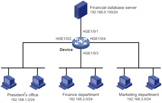
Network requirements
A company interconnects its departments through the device. Configure a packet filter to:
· Permit access from the President's office at any time to the financial database server.
· Permit access from the Finance department to the database server only during working hours (from 8:00 to 18:00) on working days.
· Deny access from any other department to the database server.
Figure 1 Network diagram
Configuration procedure
# Create a periodic time range from 8:00 to 18:00 on working days.
<Device> system-view
[Device] time-range work 08:0 to 18:00 working-day
# Create an IPv4 advanced ACL numbered 3000.
[Device] acl advanced 3000
# Configure a rule to permit access from the President's office to the financial database server.
[Device-acl-ipv4-adv-3000] rule permit ip source 192.168.1.0 0.0.0.255 destination 192.168.0.100 0
# Configure a rule to permit access from the Finance department to the database server during working hours.
[Device-acl-ipv4-adv-3000] rule permit ip source 192.168.2.0 0.0.0.255 destination 192.168.0.100 0 time-range work
# Configure a rule to deny access to the financial database server.
[Device-acl-ipv4-adv-3000] rule deny ip source any destination 192.168.0.100 0
[Device-acl-ipv4-adv-3000] quit
# Apply IPv4 advanced ACL 3000 to filter outgoing packets on interface HundredGigE 1/0/1.
[Device] interface hundredgige 1/0/1
[Device-HundredGigE1/0/1] packet-filter 3000 outbound
[Device-HundredGigE1/0/1] quit
Verifying the configuration
# Verify that a PC in the Finance department can ping the database server during working hours. (All PCs in this example use Windows XP).
C:\> ping 192.168.0.100
Pinging 192.168.0.100 with 32 bytes of data:
Reply from 192.168.0.100: bytes=32 time=1ms TTL=255
Reply from 192.168.0.100: bytes=32 time<1ms TTL=255
Reply from 192.168.0.100: bytes=32 time<1ms TTL=255
Reply from 192.168.0.100: bytes=32 time<1ms TTL=255
Ping statistics for 192.168.0.100:
Packets: Sent = 4, Received = 4, Lost = 0 (0% loss),
Approximate round trip times in milli-seconds:
Minimum = 0ms, Maximum = 1ms, Average = 0ms
# Verify that a PC in the Marketing department cannot ping the database server during working hours.
C:\> ping 192.168.0.100
Pinging 192.168.0.100 with 32 bytes of data:
Request timed out.
Request timed out.
Request timed out.
Request timed out.
Ping statistics for 192.168.0.100:
Packets: Sent = 4, Received = 0, Lost = 4 (100% loss),
# Display configuration and match statistics for IPv4 advanced ACL 3000 on the device during working hours.
[Device] display acl 3000
Advanced IPv4 ACL 3000, 3 rules,
ACL's step is 5
rule 0 permit ip source 192.168.1.0 0.0.0.255 destination 192.168.0.100 0
rule 5 permit ip source 192.168.2.0 0.0.0.255 destination 192.168.0.100 0 time-range work (Active)
rule 10 deny ip destination 192.168.0.100 0
The output shows that rule 5 is active.
QoS overview
In data communications, Quality of Service (QoS) provides differentiated service guarantees for diversified traffic in terms of bandwidth, delay, jitter, and drop rate, all of which can affect QoS.
QoS manages network resources and prioritizes traffic to balance system resources.
The following section describes typical QoS service models and widely used QoS techniques.
QoS service models
This section describes several typical QoS service models.
Best-effort service model
The best-effort model is a single-service model. The best-effort model is not as reliable as other models and does not guarantee delay-free delivery.
The best-effort service model is the default model for the Internet and applies to most network applications. It uses the First In First Out (FIFO) queuing mechanism.
IntServ model
The integrated service (IntServ) model is a multiple-service model that can accommodate diverse QoS requirements. This service model provides the most granularly differentiated QoS by identifying and guaranteeing definite QoS for each data flow.
In the IntServ model, an application must request service from the network before it sends data. IntServ signals the service request with the RSVP. All nodes receiving the request reserve resources as requested and maintain state information for the application flow. For more information about RSVP, see MPLS Configuration Guide.
The IntServ model demands high storage and processing capabilities because it requires all nodes along the transmission path to maintain resource state information for each flow. This model is suitable for small-sized or edge networks. However, it is not suitable for large-sized networks, for example, the core layer of the Internet, where billions of flows are present.
DiffServ model
The differentiated service (DiffServ) model is a multiple-service model that can meet diverse QoS requirements. It is easy to implement and extend. DiffServ does not signal the network to reserve resources before sending data, as IntServ does.
QoS techniques overview
The QoS techniques include the following features:
· Traffic classification.
· Traffic policing.
· Traffic shaping.
· Rate limit.
· Congestion management.
· Congestion avoidance.
The following section briefly introduces these QoS techniques.
All QoS techniques in this document are based on the DiffServ model.
Deploying QoS in a network
Figure 2 Position of the QoS techniques in a network
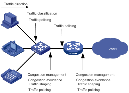
As shown in Figure 2, traffic classification, traffic shaping, traffic policing, congestion management, and congestion avoidance mainly implement the following functions:
· Traffic classification—Uses match criteria to assign packets with the same characteristics to a traffic class. Based on traffic classes, you can provide differentiated services.
· Traffic policing—Polices flows and imposes penalties to prevent aggressive use of network resources. You can apply traffic policing to both incoming and outgoing traffic of a port.
· Traffic shaping—Adapts the output rate of traffic to the network resources available on the downstream device to eliminate packet drops. Traffic shaping usually applies to the outgoing traffic of a port.
· Congestion management—Provides a resource scheduling policy to determine the packet forwarding sequence when congestion occurs. Congestion management usually applies to the outgoing traffic of a port.
· Congestion avoidance—Monitors the network resource usage. It is usually applied to the outgoing traffic of a port. When congestion worsens, congestion avoidance reduces the queue length by dropping packets.
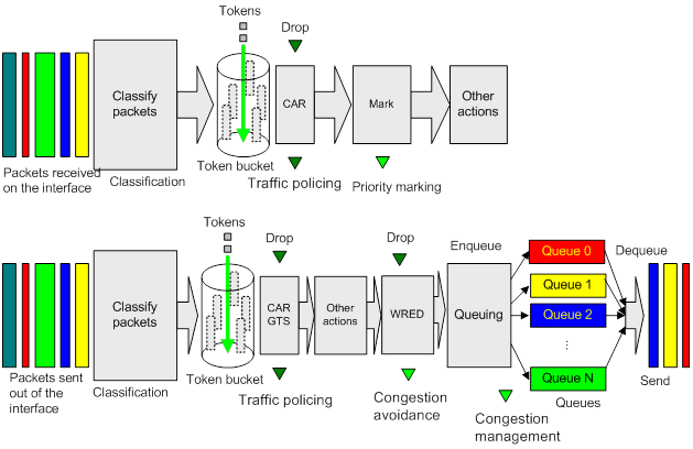
QoS processing flow in a device
Figure 3 briefly describes how the QoS module processes traffic.
1. Traffic classifier identifies and classifies traffic for subsequent QoS actions.
2. The QoS module takes various QoS actions on classified traffic as configured, depending on the traffic processing phase and network status. For example, you can configure the QoS module to perform the following operations:
? Traffic policing for incoming traffic.
? Traffic shaping for outgoing traffic.
? Congestion avoidance before congestion occurs.
? Congestion management when congestion occurs.
Configuring a QoS policy
Non-MQC approach
In the non-MQC approach, you configure QoS service parameters without using a QoS policy. For example, you can use the rate limit feature to set a rate limit on an interface without using a QoS policy.
MQC approach
In the modular QoS configuration (MQC) approach, you configure QoS service parameters by using QoS policies. A QoS policy defines policing or other QoS actions to take on different classes of traffic. It is a set of class-behavior associations.
A traffic class is a set of match criteria for identifying traffic, and it uses the AND or OR operator.
· If the operator is AND, a packet must match all the criteria to match the traffic class.
· If the operator is OR, a packet matches the traffic class if it matches any of the criteria in the traffic class.
A traffic behavior defines a set of QoS actions to take on packets, such as priority marking and redirect.
By associating a traffic behavior with a traffic class in a QoS policy, you apply QoS actions in the traffic behavior to the traffic class.
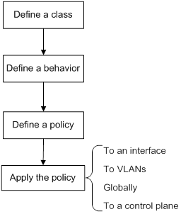
Configuration procedure diagram
Figure 4 shows how to configure a QoS policy.
Figure 4 QoS policy configuration procedure
Defining a traffic class
|
Step |
Command |
Remarks |
|
1. Enter system view. |
system-view |
N/A |
|
2. Create a traffic class and enter traffic class view. |
traffic classifier classifier-name [ operator { and | or } ] |
By default, no traffic classes exist. |
|
3. Configure a match criterion. |
if-match match-criteria |
By default, no match criterion is configured. For more information, see the if-match command in ACL and QoS Command Reference. |
Defining a traffic behavior
A traffic behavior is a set of QoS actions (such as traffic filtering, shaping, policing, and priority marking) to take on a traffic class.
To define a traffic behavior:
|
Step |
Command |
Remarks |
|
1. Enter system view. |
system-view |
N/A |
|
2. Create a traffic behavior and enter traffic behavior view. |
traffic behavior behavior-name |
By default, no traffic behaviors exist. |
|
3. Configure an action in the traffic behavior. |
See the subsequent chapters, depending on the purpose of the traffic behavior: traffic policing, traffic filtering, priority marking, class-based accounting, and so on. |
By default, no action is configured for a traffic behavior. |
Defining a QoS policy
To perform actions defined in a behavior for a class of packets, associate the behavior with the class in a QoS policy.
To associate a traffic class with a traffic behavior in a QoS policy:
|
Step |
Command |
Remarks |
|
1. Enter system view. |
system-view |
N/A |
|
2. Create a QoS policy and enter QoS policy view. |
qos policy policy-name |
By default, no QoS policies exist. |
|
3. Associate a traffic class with a traffic behavior to create a class-behavior association in the QoS policy. |
classifier classifier-name behavior behavior-name [ mode dcbx | insert-before before-classifier-name ] |
By default, a traffic class is not associated with a traffic behavior. Repeat this step to create more class-behavior associations. The mode dcbx keyword specifies that a class-behavior association applies only to DCBX. For more information about DCBX, see Layer 2—LAN Switching Configuration Guide. |
Applying the QoS policy
You can apply a QoS policy to the following destinations:
· Interface—The QoS policy takes effect on the traffic sent or received on the interface.
· VLAN—The QoS policy takes effect on the traffic sent or received on all ports in the VLAN.
· Globally—The QoS policy takes effect on the traffic sent or received on all ports.
· Control plane—The QoS policy takes effect on the traffic received on the control plane.
You can modify traffic classes, traffic behaviors, and class-behavior associations in a QoS policy even after it is applied. If a traffic class uses an ACL for traffic classification, you can delete or modify the ACL.
Applying the QoS policy to an interface
A QoS policy can be applied to multiple interfaces. However, only one QoS policy can be applied to one direction (inbound or outbound) of an interface.
The QoS policy applied to the outgoing traffic on an interface does not regulate local packets. Local packets refer to critical protocol packets sent by the local system for operation maintenance. The most common local packets include link maintenance, routing, LDP, RSVP, and SSH packets.
QoS policies can be applied to Layer 2 Ethernet interfaces, Layer 2 aggregate interfaces, Layer 3 Ethernet interfaces, Layer 3 aggregate interfaces, and VSI interfaces. The term "interface" in this section collectively refers to these types of interfaces. You can use the port link-mode command to configure an Ethernet port as a Layer 2 or Layer 3 interface (see Layer 2—LAN Switching Configuration Guide).
To apply a QoS policy to an interface:
|
Step |
Command |
Remarks |
|
1. Enter system view. |
system-view |
N/A |
|
2. Enter interface view. |
interface interface-type interface-number |
N/A |
|
3. Apply the QoS policy to the interface. |
qos apply policy policy-name { inbound | outbound } |
By default, no QoS policy is applied to an interface. |
Applying the QoS policy to VLANs
You can apply a QoS policy to VLANs to regulate traffic of the VLANs.
Configuration restrictions and guidelines
When you apply a QoS policy to VLANs, follow these restrictions and guidelines:
· QoS policies cannot be applied to dynamic VLANs, including VLANs created by GVRP.
· If the hardware resources of an interface module are insufficient, applying a QoS policy to VLANs might fail on the interface module. The system does not automatically roll back the QoS policy configuration already applied to other interface modules. To ensure consistency, use the undo qos vlan-policy vlan command to manually remove the QoS policy configuration applied to them.
Configuration procedure
To apply the QoS policy to VLANs:
|
Step |
Command |
Remarks |
|
1. Enter system view. |
system-view |
N/A |
|
2. Apply the QoS policy to VLANs. |
qos vlan-policy policy-name vlan vlan-id-list { inbound | outbound } |
By default, no QoS policy is applied to a VLAN. |
Applying the QoS policy globally
You can apply a QoS policy globally to the inbound or outbound direction of all ports.
If the hardware resources of an interface module are insufficient, applying a QoS policy globally might fail on the interface module. The system does not automatically roll back the QoS policy configuration already applied to other interface modules. To ensure consistency, use the undo qos apply policy global command to manually remove the QoS policy configuration applied to them.
To apply the QoS policy globally:
|
Step |
Command |
Remarks |
|
1. Enter system view. |
system-view |
N/A |
|
2. Apply the QoS policy globally. |
qos apply policy policy-name global { inbound | outbound } |
By default, no QoS policy is applied globally. |
Applying the QoS policy to a control plane
A device provides the data plane and the control plane.
· Data plane—The units at the data plane are responsible for receiving, transmitting, and switching (forwarding) packets, such as various dedicated forwarding chips. They deliver super processing speeds and throughput.
· Control plane—The units at the control plane are processing units running most routing and switching protocols. They are responsible for protocol packet resolution and calculation, such as CPUs. Compared with data plane units, the control plane units allow for great packet processing flexibility but have lower throughput.
When the data plane receives packets that it cannot recognize or process, it transmits them to the control plane. If the transmission rate exceeds the processing capability of the control plane, the control plane will be busy handling undesired packets. As a result, the control plane will fail to handle legitimate packets correctly or timely. As a result, protocol performance is affected.
To address this problem, apply a QoS policy to the control plane to take QoS actions, such as traffic filtering or rate limiting, on inbound traffic. This ensures that the control plane can correctly receive, transmit, and process packets.
A predefined control plane QoS policy uses the protocol type or protocol group type to identify the type of packets sent to the control plane. You can use protocol types or protocol group types in if-match commands in traffic class view for traffic classification. Then you can reconfigure traffic behaviors for these traffic classes as required. You can use the display qos policy control-plane pre-defined command to display predefined control plane QoS policies.
Configuration restrictions and guidelines
When you apply a QoS policy to a control plane, follow these restrictions and guidelines:
· If the hardware resources of an interface module are insufficient, applying a QoS policy globally might fail on the interface module. The system does not automatically roll back the QoS policy configuration already applied to other interface modules. To ensure consistency, use the undo qos apply policy command to manually remove the QoS policy configuration applied to them.
· If a class uses control plane protocols or control plane protocol groups as match criteria, the action in the associated traffic behavior can only be car or the combination of car and accounting packet. Only the cir keyword in the car action can be applied correctly.
Configuration procedure
To apply the QoS policy to a control plane:
|
Step |
Command |
Remarks |
|
1. Enter system view. |
system-view |
N/A |
|
2. Enter control plane view. |
In standalone mode: In IRF mode: |
N/A |
|
3. Apply the QoS policy to the control plane. |
qos apply policy policy-name inbound |
By default, no QoS policy is applied to a control plane. |
Displaying and maintaining QoS policies
Execute display commands in any view and reset commands in user view.
|
Task |
Command |
|
(In standalone mode.) Display traffic class configuration. |
display traffic classifier user-defined [ classifier-name ] [ slot slot-number ] |
|
(In IRF mode.) Display traffic class configuration. |
display traffic classifier user-defined [ classifier-name ] [ chassis chassis-number slot slot-number ] |
|
(In standalone mode.) Display traffic behavior configuration. |
display traffic behavior user-defined [ behavior-name ] [ slot slot-number ] |
|
(In IRF mode.) Display traffic behavior configuration. |
display traffic behavior user-defined [ behavior-name ] [ chassis chassis-number slot slot-number ] |
|
(In standalone mode.) Display QoS and ACL resource usage. |
display qos-acl resource [ slot slot-number ] |
|
(In IRF mode.) Display QoS and ACL resource usage. |
display qos-acl resource [ chassis chassis-number slot slot-number ] |
|
(In standalone mode.) Display QoS policy configuration. |
display qos policy user-defined [ policy-name [ classifier classifier-name ] ] [ slot slot-number ] |
|
(In IRF mode.) Display QoS policy configuration. |
display qos policy user-defined [ policy-name [ classifier classifier-name ] ] [ chassis chassis-number slot slot-number ] |
|
(In standalone mode.) Display information about QoS policies applied to interfaces. |
display qos policy interface [ interface-type interface-number ] [ slot slot-number ] [ inbound | outbound ] |
|
(In IRF mode.) Display information about QoS policies applied to interfaces. |
display qos policy interface [ interface-type interface-number ] [ chassis chassis-number slot slot-number ] [ inbound | outbound ] |
|
(In standalone mode.) Display information about QoS policies applied to VLANs. |
display qos vlan-policy { name policy-name | vlan vlan-id } [ slot slot-number ] [ inbound | outbound ] |
|
(In IRF mode.) Display information about QoS policies applied to VLANs. |
display qos vlan-policy { name policy-name | vlan [ vlan-id ] } [ chassis chassis-number slot slot-number ] [ inbound | outbound ] |
|
(In standalone mode.) Display information about QoS policies applied globally. |
display qos policy global [ slot slot-number ] [ inbound | outbound ] |
|
(In IRF mode.) Display information about QoS policies applied globally. |
display qos policy global [ chassis chassis-number slot slot-number ] [ inbound | outbound ] |
|
(In standalone mode.) Display information about QoS policies applied to a control plane. |
display qos policy control-plane slot slot-number |
|
(In IRF mode.) Display information about QoS policies applied to a control plane. |
display qos policy control-plane chassis chassis-number slot slot-number |
|
(In standalone mode.) Display information about the predefined QoS policy applied to the control plane. |
display qos policy control-plane pre-defined [ slot slot-number ] |
|
(In IRF mode.) Display information about the predefined QoS policy applied to the control plane. |
display qos policy control-plane pre-defined [ chassis chassis-number slot slot-number ] |
|
Clear the statistics of the QoS policy applied in a certain direction of a VLAN. |
reset qos vlan-policy [ vlan vlan-id ] [ inbound | outbound ] |
|
Clear the statistics for a QoS policy applied globally. |
reset qos policy global [ inbound | outbound ] |
|
(In standalone mode.) Clear the statistics for the QoS policy applied to a control plane. |
reset qos policy control-plane slot slot-number |
|
(In IRF mode.) Clear the statistics for the QoS policy applied to a control plane. |
reset qos policy control-plane chassis chassis-number slot slot-number |
Configuring priority mapping
Both Layer 2 and Layer 3 Ethernet interfaces support priority mapping. The term "interface" in this chapter collectively refers to these two types of interfaces. You can use the port link-mode command to configure an Ethernet port as a Layer 2 or Layer 3 interface (see Layer 2—LAN Switching Configuration Guide).
Overview
When a packet arrives, a device assigns a set of QoS priority parameters to the packet based on either of the following:
· A priority field carried in the packet.
· The port priority of the incoming port.
This process is called priority mapping. During this process, the device can modify the priority of the packet according to the priority mapping rules. The set of QoS priority parameters decides the scheduling priority and forwarding priority of the packet.
Priority mapping is implemented with priority maps and involves the following priorities:
· 802.1p priority.
· DSCP.
· EXP.
· IP precedence.
· Local precedence.
· Drop priority.
Introduction to priorities
Priorities include the following types: priorities carried in packets, and priorities locally assigned for scheduling only.
Packet-carried priorities include 802.1p priority, DSCP precedence, IP precedence, and EXP. These priorities have global significance and affect the forwarding priority of packets across the network. For more information about these priorities, see "Appendixes."
Locally assigned priorities only have local significance. They are assigned by the device only for scheduling. These priorities include the local precedence, drop priority, and user priority, as follows:
· Local precedence—Used for queuing. A local precedence value corresponds to an output queue. A packet with higher local precedence is assigned to a higher priority output queue to be preferentially scheduled.
· Drop priority—Used for making packet drop decisions. Packets with the highest drop priority are dropped preferentially.
Priority maps
The device provides various types of priority maps. By looking through a priority map, the device decides which priority value to assign to a packet for subsequent packet processing.
The default priority maps (as shown in Appendix B Default priority maps) are available for priority mapping. They are adequate in most cases. If a default priority map cannot meet your requirements, you can modify the priority map as required.
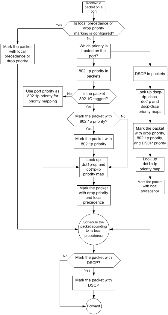
Priority mapping process
On receiving an Ethernet packet on a port, the switch marks the scheduling priorities (local precedence and drop precedence) for the Ethernet packet. This procedure is done according to the priority trust mode of the receiving port and the 802.1Q tagging status of the packet, as shown in Figure 5.
Figure 5 Priority mapping process for an Ethernet packet
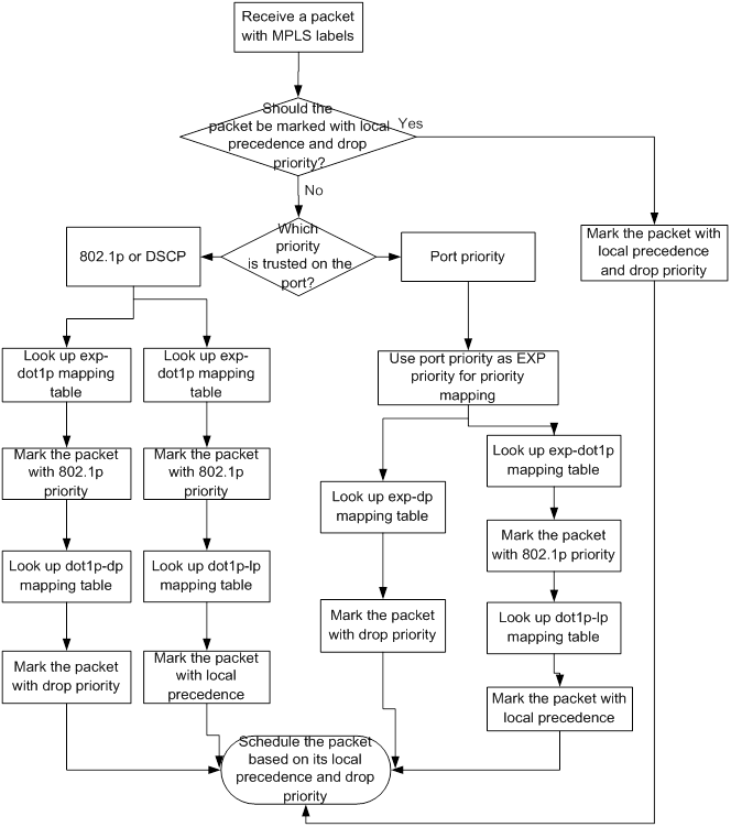
The switch marks a received MPLS packet with a scheduling priority based on the priority trust mode and the packet EXP value, as shown in Figure 6.
Figure 6 Priority mapping process for an MPLS packet
For information about priority marking, see "Configuring priority mapping."
Priority mapping configuration tasks
You can configure priority mapping by using any of the following methods:
· Configuring priority trust mode—In this method, you can configure an interface to look up a trusted priority type (802.1p, for example) in incoming packets in the priority maps. Then, the system maps the trusted priority to the target priority types and values.
· Changing port priority—If no packet priority is trusted, the port priority of the incoming interface is used. By changing the port priority of an interface, you change the priority of the incoming packets on the interface.
To configure priority mapping, perform the following tasks:
|
Tasks at a glance |
|
(Optional.) Configuring a priority map |
|
(Required.) Perform one of the following tasks: · Configuring an interface to trust packet priority for priority mapping · Changing the port priority of an interface |
Configuring a priority map
The device provides the following types of priority map:
|
Priority map |
Description |
|
dot1p-dp |
802.1p-drop priority map. |
|
dot1p-lp |
802.1p-local priority map. |
|
dscp-dot1p |
DSCP-802.1p priority map. |
|
dscp-dp |
DSCP-drop priority map. |
|
dscp-dscp |
DSCP-DSCP priority map. |
|
exp-dot1p |
EXP-802.1p priority map. |
|
exp-dscp |
EXP-DSCP priority map. |
To configure a priority map:
|
Step |
Command |
Remarks |
|
1. Enter system view. |
system-view |
N/A |
|
2. Enter priority map view. |
qos map-table { dot1p-dp | dot1p-lp | dscp-dot1p | dscp-dp | dscp-dscp | exp-dot1p | exp-dscp } |
N/A |
|
3. Configure mappings for the priority map. |
import import-value-list export export-value |
By default, the default priority maps are used. For more information, see "Appendixes." If you execute this command multiple times, the most recent configuration takes effect. |
Configuring an interface to trust packet priority for priority mapping
You can configure the device to trust a particular priority field carried in packets for priority mapping on interfaces or globally.
When you configure the trusted packet priority type on an interface, use the following available keywords:
· dot1p—Uses the 802.1p priority of received packets for mapping.
· dscp—Uses the DSCP precedence of received IP packets for mapping.
To configure the trusted packet priority type on an interface:
|
Step |
Command |
Remarks |
|
1. Enter system view. |
system-view |
N/A |
|
2. Enter interface view. |
interface interface-type interface-number |
N/A |
|
3. Configure the trusted packet priority type. |
qos trust { dot1p | dscp } |
By default, the switch trusts the 802.1p priority of incoming packets. |
Changing the port priority of an interface
If an interface does not trust any packet priority, the device uses its port priority to look for priority parameters for the incoming packets. By changing the port priority, you can prioritize traffic received on different interfaces.
To change the port priority of an interface:
|
Step |
Command |
Remarks |
|
1. Enter system view. |
system-view |
N/A |
|
2. Enter interface view. |
interface interface-type interface-number |
N/A |
|
3. Set the port priority of the interface. |
qos priority priority-value |
The default setting is 0. |
Displaying and maintaining priority mapping
Execute display commands in any view.
|
Task |
Command |
|
Display priority map configuration. |
display qos map-table [ dot1p-dp | dot1p-lp | dscp-dot1p | dscp-dp | dscp-dscp | exp-dot1p | exp-dscp ] |
|
Display the trusted packet priority type on an interface. |
display qos trust interface [ interface-type interface-number ] |
Priority mapping configuration examples
Port priority configuration example
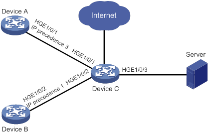
Network requirements
As shown in Figure 7:
· The IP precedence of traffic from Device A to Device C is 3.
· The IP precedence of traffic from Device B to Device C is 1.
Configure Device C to preferentially process packets from Device A to the server when HundredGigE 1/0/3 of Device C is congested.
Configuration procedure
# Assign port priority to HundredGigE 1/0/1 and HundredGigE 1/0/2. Make sure the priority of HundredGigE 1/0/1 is higher than that of HundredGigE 1/0/2.
<DeviceC> system-view
[DeviceC] interface hundredgige 1/0/1
[DeviceC-HundredGigE1/0/1] qos priority 3
[DeviceC-HundredGigE1/0/1] quit
[DeviceC] interface hundredgige 1/0/2
[DeviceC-HundredGigE1/0/2] qos priority 1
[DeviceC-HundredGigE1/0/2] quit
Priority mapping table and priority marking configuration example
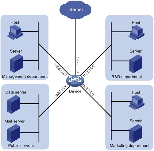
Network requirements
As shown in Figure 8:
· The Marketing department connects to HundredGigE 1/0/1 of Device, which sets the 802.1p priority of traffic from the Marketing department to 3.
· The R&D department connects to HundredGigE 1/0/2 of Device, which sets the 802.1p priority of traffic from the R&D department to 4.
· The Management department connects to HundredGigE 1/0/3 of Device, which sets the 802.1p priority of traffic from the Management department to 5.
Configure port priority, 802.1p-to-local mapping table, and priority marking to implement the plan as described in Table 2.
|
Traffic destination |
Traffic priority order |
Queuing plan |
||
|
Traffic source |
Output queue |
Queue priority |
||
|
Public servers |
R&D department > Management department > Marketing department |
R&D department |
6 |
High |
|
Management department |
4 |
Medium |
||
|
Marketing department |
2 |
Low |
||
|
Internet |
Management department > Marketing department > R&D department |
R&D department |
2 |
Low |
|
Management department |
6 |
High |
||
|
Marketing department |
4 |
Medium |
||
Configuration procedure
1. Configure trusting port priority:
# Set the port priority of HundredGigE 1/0/1 to 3.
<Device> system-view
[Device] interface hundredgige 1/0/1
[Device-HundredGigE1/0/1] qos priority 3
[Device-HundredGigE1/0/1] quit
# Set the port priority of HundredGigE 1/0/2 to 4.
[Device] interface hundredgige 1/0/2
[Device-HundredGigE1/0/2] qos priority 4
[Device-HundredGigE1/0/2] quit
# Set the port priority of HundredGigE 1/0/3 to 5.
[Device] interface hundredgige 1/0/3
[Device-HundredGigE1/0/3] qos priority 5
[Device-HundredGigE1/0/3] quit
2. Configure the 802.1p-to-local mapping table to map 802.1p priority values 3, 4, and 5 to local precedence values 2, 6, and 4.
This guarantees the R&D department, Management department, and Marketing department decreased priorities to access the public servers.
[Device] qos map-table dot1p-lp
[Device-maptbl-dot1p-lp] import 3 export 2
[Device-maptbl-dot1p-lp] import 4 export 6
[Device-maptbl-dot1p-lp] import 5 export 4
[Device-maptbl-dot1p-lp] quit
3. Configure priority marking:
# Create ACL 3000, and configure a rule to match HTTP packets.
[Device] acl advance 3000
[Device-acl-adv-3000] rule permit tcp destination-port eq 80
[Device-acl-adv-3000] quit
# Create a traffic class named http, and use ACL 3000 as a match criterion.
[Device] traffic classifier http
[Device-classifier-http] if-match acl 3000
[Device-classifier-http] quit
# Create a traffic behavior named admin, and configure a marking action for the Management department.
[Device] traffic behavior admin
[Device-behavior-admin] remark dot1p 4
[Device-behavior-admin] quit
# Create a QoS policy named admin, and associate traffic class http with traffic behavior admin in QoS policy admin.
[Device] qos policy admin
[Device-qospolicy-admin] classifier http behavior admin
[Device-qospolicy-admin] quit
# Apply QoS policy admin to the inbound direction of HundredGigE 1/0/3.
[Device] interface hundredgige 1/0/3
[Device-HundredGigE1/0/3] qos apply policy admin inbound
# Create a traffic behavior named market, and configure a marking action for the Marketing department.
[Device] traffic behavior market
[Device-behavior-market] remark dot1p 5
[Device-behavior-market] quit
# Create a QoS policy named market, and associate traffic class http with traffic behavior market in QoS policy market.
[Device] qos policy market
[Device-qospolicy-market] classifier http behavior market
[Device-qospolicy-market] quit
# Apply QoS policy market to the inbound direction of HundredGigE 1/0/1.
[Device] interface hundredgige 1/0/1
[Device-HundredGigE1/0/1] qos apply policy market inbound
# Create a traffic behavior named rd, and configure a marking action for the R&D department.
[Device] traffic behavior rd
[Device-behavior-rd] remark dot1p 3
[Device-behavior-rd] quit
# Create a QoS policy named rd, and associate traffic class http with traffic behavior rd in QoS policy rd.
[Device] qos policy rd
[Device-qospolicy-rd] classifier http behavior rd
[Device-qospolicy-rd] quit
# Apply QoS policy rd to the inbound direction of HundredGigE 1/0/2.
[Device] interface hundredgige 1/0/2
[Device-HundredGigE1/0/2] qos apply policy rd inbound
Configuring traffic policing, GTS, and rate limit
Overview
Traffic policing helps assign network resources (including bandwidth) and increase network performance. For example, you can configure a flow to use only the resources committed to it in a certain time range. This avoids network congestion caused by burst traffic.
Traffic policing, Generic Traffic Shaping (GTS), and rate limit control the traffic rate and resource usage according to traffic specifications. You can use token buckets for evaluating traffic specifications.
Traffic evaluation and token buckets
Token bucket features
A token bucket is analogous to a container that holds a certain number of tokens. Each token represents a certain forwarding capacity. The system puts tokens into the bucket at a constant rate. When the token bucket is full, the extra tokens cause the token bucket to overflow.
Evaluating traffic with the token bucket
A token bucket mechanism evaluates traffic by looking at the number of tokens in the bucket. If the number of tokens in the bucket is enough for forwarding the packets:
· The traffic conforms to the specification (called conforming traffic).
· The corresponding tokens are taken away from the bucket.
Otherwise, the traffic does not conform to the specification (called excess traffic).
A token bucket has the following configurable parameters:
· Mean rate at which tokens are put into the bucket, which is the permitted average rate of traffic. It is usually set to the committed information rate (CIR).
· Burst size or the capacity of the token bucket. It is the maximum traffic size permitted in each burst. It is usually set to the committed burst size (CBS). The set burst size must be greater than the maximum packet size.
Each arriving packet is evaluated.
Complicated evaluation
You can set two token buckets, bucket C and bucket E, to evaluate traffic in a more complicated environment and achieve more policing flexibility. For example, traffic policing uses the following mechanisms:
· Single rate two color—Uses one token bucket and the following parameters:
? CIR—Rate at which tokens are put into bucket C. It sets the average packet transmission or forwarding rate allowed by bucket C.
? CBS—Size of bucket C, which specifies the transient burst of traffic that bucket C can forward.
When a packet arrives, the following rules apply:
? If bucket C has enough tokens to forward the packet, the packet is colored green.
? Otherwise, the packet is colored red.
· Single rate three color—Uses two token buckets and the following parameters:
? CIR—Rate at which tokens are put into bucket C. It sets the average packet transmission or forwarding rate allowed by bucket C.
? CBS—Size of bucket C, which specifies the transient burst of traffic that bucket C can forward.
? EBS—Size of bucket E minus size of bucket C, which specifies the transient burst of traffic that bucket E can forward. The EBS cannot be 0. The size of E bucket is the sum of the CBS and EBS.
When a packet arrives, the following rules apply:
? If bucket C has enough tokens, the packet is colored green.
? If bucket C does not have enough tokens but bucket E has enough tokens, the packet is colored yellow.
? If neither bucket C nor bucket E has sufficient tokens, the packet is colored red.
· Two rate three color—Uses two token buckets and the following parameters:
? CIR—Rate at which tokens are put into bucket C. It sets the average packet transmission or forwarding rate allowed by bucket C.
? CBS—Size of bucket C, which specifies the transient burst of traffic that bucket C can forward.
? PIR—Rate at which tokens are put into bucket E, which specifies the average packet transmission or forwarding rate allowed by bucket E.
? EBS—Size of bucket E, which specifies the transient burst of traffic that bucket E can forward.
When a packet arrives, the following rules apply:
? If bucket C has enough tokens, the packet is colored green.
? If bucket C does not have enough tokens but bucket E has enough tokens, the packet is colored yellow.
? If neither bucket C nor bucket E has sufficient tokens, the packet is colored red.
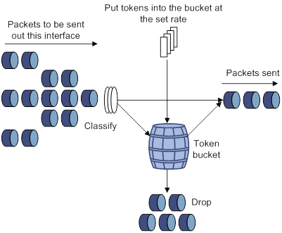
Traffic policing
A typical application of traffic policing is to supervise the specification of traffic entering a network and limit it within a reasonable range. Another application is to "discipline" the extra traffic to prevent aggressive use of network resources by an application. For example, you can limit bandwidth for HTTP packets to less than 50% of the total. If the traffic of a session exceeds the limit, traffic policing can drop the packets or reset the IP precedence of the packets. Figure 9 shows an example of policing outbound traffic on an interface.
Traffic policing is widely used in policing traffic entering the ISP networks. It can classify the policed traffic and take predefined policing actions on each packet depending on the evaluation result:
· Forwarding the packet if the evaluation result is "conforming."
· Dropping the packet if the evaluation result is "excess."
The switch is programmed to forward green packets and yellow packets and to drop red packets.
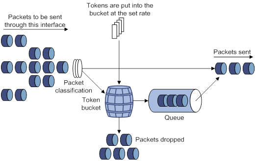
GTS
GTS supports shaping the outbound traffic. GTS limits the outbound traffic rate by buffering exceeding traffic. You can use GTS to adapt the traffic output rate on a device to the input traffic rate of its connected device to avoid packet loss.
The differences between traffic policing and GTS are as follows:
· Packets to be dropped with traffic policing are retained in a buffer or queue with GTS, as shown in Figure 10. When enough tokens are in the token bucket, the buffered packets are sent at an even rate.
· GTS can result in additional delay and traffic policing does not.
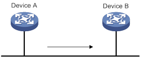
For example, in Figure 11, Device B performs traffic policing on packets from Device A and drops packets exceeding the limit. To avoid packet loss, you can perform GTS on the outgoing interface of Device A so that packets exceeding the limit are cached in Device A. Once resources are released, GTS takes out the cached packets and sends them out.
Rate limit
The rate limit of an interface specifies the maximum rate for sending packets (including critical packets).
Rate limit also uses token buckets for traffic control. When rate limit is configured on an interface, a token bucket handles all packets to be sent through the interface for rate limiting. If enough tokens are in the token bucket, packets can be forwarded. Otherwise, packets are put into QoS queues for congestion management. In this way, the traffic passing the interface is controlled.
Figure 12 Rate limit implementation
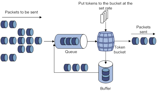
The token bucket mechanism limits traffic rate when accommodating bursts. It allows bursty traffic to be transmitted if enough tokens are available. If tokens are scarce, packets cannot be transmitted until efficient tokens are generated in the token bucket. It restricts the traffic rate to the rate for generating tokens.
Rate limit controls the total rate of all packets on an interface. It is easier to use than traffic policing in controlling the total traffic rate.
Configuring traffic policing by using the MQC approach
|
Step |
Command |
Remarks |
|
1. Enter system view. |
system-view |
N/A |
|
2. Create a traffic class and enter traffic class view. |
traffic classifier classifier-name [ operator { and | or } ] |
By default, no traffic classes exist. |
|
3. Configure a match criterion. |
if-match match-criteria |
By default, no match criterion is configured. For more information about the if-match command, see ACL and QoS Command Reference. |
|
4. Return to system view. |
quit |
N/A |
|
5. Create a traffic behavior and enter traffic behavior view. |
traffic behavior behavior-name |
By default, no traffic behaviors exist. |
|
6. Configure a traffic policing action. |
car cir committed-information-rate [ cbs committed-burst-size [ ebs excess-burst-size ] ] car cir committed-information-rate [ cbs committed-burst-size ] pir peak-information-rate [ ebs excess-burst-size ] |
By default, no traffic policing action is configured. |
|
7. Return to system view. |
quit |
N/A |
|
8. Create a QoS policy and enter QoS policy view. |
qos policy policy-name |
By default, no QoS policies exist. |
|
9. Associate the traffic class with the traffic behavior in the QoS policy. |
classifier classifier-name behavior behavior-name [ mode dcbx | insert-before before-classifier-name ] |
By default, a traffic class is not associated with a traffic behavior. The mode dcbx keyword specifies that a class-behavior association applies only to DCBX. For more information about DCBX, see Layer 2—LAN Switching Configuration Guide. |
|
10. Return to system view. |
quit |
N/A |
|
11. Apply the QoS policy. |
· Applying the QoS policy to an interface · Applying the QoS policy to VLANs · Applying the QoS policy globally · Applying the QoS policy to a control plane |
Choose one of the application destinations as needed. By default, no QoS policy is applied. A traffic policing action takes effect only when the QoS policy is applied to the inbound direction. |
Configuring GTS by using the non-MQC approach
You can configure queue-based GTS by using the non-MQC approach.
To configure queue-based GTS:
|
Step |
Command |
Remarks |
|
1. Enter system view. |
system-view |
N/A |
|
2. Enter interface view. |
interface interface-type interface-number |
N/A |
|
3. Configure GTS for a queue. |
qos gts queue queue-id cir committed-information-rate [ cbs committed-burst-size ] |
By default, GTS is not configured on an interface. |
Configuring the rate limit for an interface
The rate limit for an interface specifies the maximum rate of outgoing packets on the interface.
Both Layer 2 and Layer 3 Ethernet interfaces support the rate limit feature. The term "interface" in this section collectively refers to these two types of interfaces. You can use the port link-mode command to configure an Ethernet port as a Layer 2 or Layer 3 interface (see Layer 2—LAN Switching Configuration Guide).
To configure the rate limit for an interface:
|
Step |
Command |
Remarks |
|
1. Enter system view. |
system-view |
N/A |
|
2. Enter interface view. |
interface interface-type interface-number |
N/A |
|
3. Configure the rate limit for the interface. |
qos lr outbound cir committed-information-rate [ cbs committed-burst-size ] |
By default, no rate limit is configured on an interface. |
Displaying and maintaining traffic policing, GTS, and rate limit
Execute display commands in any view.
|
Task |
Command |
|
(In standalone mode.) Display QoS and ACL resource usage. |
display qos-acl resource [ slot slot-number ] |
|
(In IRF mode.) Display QoS and ACL resource usage. |
display qos-acl resource [ chassis chassis-number slot slot-number ] |
|
Display traffic behavior configuration. |
display traffic behavior user-defined [ behavior-name ] [ slot slot-number ] |
|
Display GTS configuration and statistics for interfaces. |
display qos gts interface [ interface-type interface-number ] |
|
Display rate limit configuration and statistics for interfaces. |
display qos lr interface [ interface-type interface-number ] |
Traffic policing configuration example
Network requirements
As shown in Figure 13:
· The server, Host A, and Host B can access the Internet through Device A and Device B.
· The server, Host A, and HundredGigE 1/0/1 of Device A are in the same network segment.
Perform traffic control for the packets that HundredGigE 1/0/1 of Device A receives from the server and Host A using the following guidelines:
· Limit the rate of packets from the server to 10240 kbps. When the traffic rate is below 10240 kbps, the traffic is forwarded. When the traffic rate exceeds 10240 kbps, the excess packets are dropped.
· Limit the rate of packets from Host A to 2560 kbps. When the traffic rate is below 2560 kbps, the traffic is forwarded. When the traffic rate exceeds 2560 kbps, the excess packets are dropped.
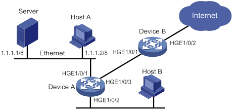
Configuration procedure
1. Configure Device A:
# Configure ACL 2001 and ACL 2002 to permit the packets from the server and Host A, respectively.
[DeviceA] acl basic 2001
[DeviceA-acl-ipv4-basic-2001] rule permit source 1.1.1.1 0
[DeviceA-acl-ipv4-basic-2001] quit
[DeviceA] acl basic 2002
[DeviceA-acl-ipv4-basic-2002] rule permit source 1.1.1.2 0
[DeviceA-acl-ipv4-basic-2002] quit
# Create a traffic class named server, and use ACL 2001 as the match criterion.
[DeviceA] traffic classifier server
[DeviceA-classifier-server] if-match acl 2001
[DeviceA-classifier-server] quit
# Create a traffic class named host, and use ACL 2002 as the match criterion.
[DeviceA] traffic classifier host
[DeviceA-classifier-host] if-match acl 2002
[DeviceA-classifier-host] quit
# Create a traffic behavior named server, and configure a traffic policing action (CIR 10240 kbps). No configuration is required for red packets (excess packets), because they are dropped by default.
[DeviceA] traffic behavior server
[DeviceA-behavior-server] car cir 10240
[DeviceA-behavior-server] quit
# Create a traffic behavior named host, and configure a traffic policing action (CIR 2560 kbps).
[DeviceA] traffic behavior host
[DeviceA-behavior-host] car cir 2560
[DeviceA-behavior-host] quit
# Create a QoS policy named car, and associate traffic classes server and host with traffic behaviors server and host in QoS policy car, respectively.
[DeviceA] qos policy car
[DeviceA-qospolicy-car] classifier server behavior server
[DeviceA-qospolicy-car] classifier host behavior host
[DeviceA-qospolicy-car] quit
# Apply QoS policy car to the inbound direction of HundredGigE 1/0/1.
[DeviceA] interface hundredgige 1/0/1
[DeviceA-HundredGigE1/0/1] qos apply policy car inbound
Configuring congestion management
Overview
Congestion occurs on a link or node when traffic size exceeds the processing capability of the link or node. It is typical of a statistical multiplexing network and can be caused by link failures, insufficient resources, and various other causes.
Figure 14 shows two typical congestion scenarios.
Figure 14 Traffic congestion scenarios
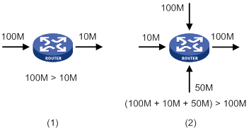
Congestion produces the following negative results:
· Increased delay and jitter during packet transmission.
· Decreased network throughput and resource use efficiency.
· Network resource (memory, in particular) exhaustion and even system breakdown.
Congestion is unavoidable in switched networks and multiuser application environments. To improve the service performance of your network, take measures to manage and control it.
The key to congestion management is defining a resource dispatching policy to prioritize packets for forwarding when congestion occurs.
Congestion management uses queuing and scheduling algorithms to classify and sort traffic leaving a port.
The switch supports the following queuing mechanisms.
SP queuing
SP queuing is designed for mission-critical applications that require preferential service to reduce the response delay when congestion occurs.
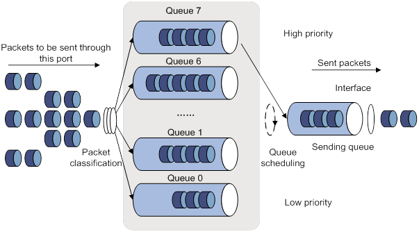
In Figure 15, SP queuing classifies eight queues on an interface into eight classes, numbered 7 to 0 in descending priority order.
SP queuing schedules the eight queues in the descending order of priority. SP queuing sends packets in the queue with the highest priority first. When the queue with the highest priority is empty, it sends packets in the queue with the second highest priority, and so on. You can assign mission-critical packets to a high priority queue to make sure they are always served first. Common service packets can be assigned to low priority queues to be transmitted when high priority queues are empty.
The disadvantage of SP queuing is that packets in the lower priority queues cannot be transmitted if packets exist in the higher priority queues. In the worst case, lower priority traffic might never get serviced.
WRR queuing
WRR queuing schedules all the queues in turn to ensure that every queue is served for a certain time, as shown in Figure 16.
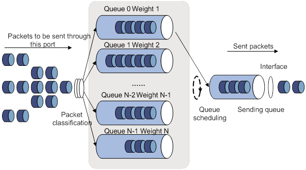
Assume an interface provides eight output queues. WRR assigns each queue a weight value (represented by w7, w6, w5, w4, w3, w2, w1, or w0). The weight value of a queue decides the proportion of resources assigned to the queue. On a 100 Mbps interface, you can set the weight values to 50, 30, 10, 10, 50, 30, 10, and 10 for w7 through w0. In this way, the queue with the lowest priority can get a minimum of 5 Mbps of bandwidth. WRR solves the problem that SP queuing might fail to serve packets in low-priority queues for a long time.
Another advantage of WRR queuing is that when the queues are scheduled in turn, the service time for each queue is not fixed. If a queue is empty, the next queue will be scheduled immediately. This improves bandwidth resource use efficiency.
WRR queuing includes the following types:
· Basic WRR queuing—Contains multiple queues. You can set the weight for each queue, and WRR schedules these queues based on the user-defined parameters in a round robin manner.
· Group-based WRR queuing—All the queues are scheduled by WRR. You can divide output queues to WRR priority queue group 1 and WRR priority queue group 2. Round robin queue scheduling is performed for group 1 first. If group 1 is empty, round robin queue scheduling is performed for group 2.
On an interface enabled with group-based WRR queuing, you can assign queues to the SP group. Queues in the SP group are scheduled with SP. The SP group has higher scheduling priority than the WRR groups.
Only group-based WRR queuing is supported in the current software version, and only WRR group 1 is supported.
WFQ queuing
Figure 17 WFQ queuing
WFQ is similar to WRR. The difference is that WFQ enables you to set guaranteed bandwidth that a WFQ queue can get during congestion.
On an interface with WFQ queuing enabled, you can assign queues to the SP group. Queues in the SP group are scheduled with SP. The SP group has higher scheduling priority than the WFQ groups.
Configuration approaches and task list
The following are approaches to congestion management configuration:
· Configure queue scheduling for each queue in interface view, as described in "Configuring per-queue ."
· Configure a queue scheduling profile, as described in "Configuring a queue scheduling profile."
Both Layer 2 and Layer 3 Ethernet interfaces support the congestion management feature. The term "interface" in this section collectively refers to these two types of interfaces. You can use the port link-mode command to configure an Ethernet port as a Layer 2 or Layer 3 interface (see Layer 2—LAN Switching Configuration Guide).
To achieve congestion management, perform the following tasks:
|
Tasks at a glance |
|
|
(Required.) Perform one of the following tasks to configure per-queue congestion management: · Configuring SP queuing · Configuring WRR queuing · Configuring WFQ queuing |
|
|
(Required.) Configuring a queue scheduling profile |
Configuring per-queue congestion management
In per-queue congestion management, you manage traffic congestion on a per-queue basis on interfaces.
Configuring SP queuing
|
Step |
Command |
Remarks |
|
1. Enter system view. |
system-view |
N/A |
|
2. Enter interface view. |
interface interface-type interface-number |
N/A |
|
3. Configure SP queuing. |
qos sp |
By default, SP queuing is used on an interface. |
Configuring WRR queuing
|
Step |
Command |
Remarks |
|
1. Enter system view. |
system-view |
N/A |
|
2. Enter interface view. |
interface interface-type interface-number |
N/A |
|
3. Enable WRR queuing. |
qos wrr { byte-count | weight } |
By default, SP queuing is used on an interface. |
|
4. Set the scheduling weight for a queue. |
qos wrr queue-id group 1 { byte-count | weight } schedule-value |
By default, queues 0 through 7 are in WRR group 1 and have a weight of 1, 2, 3, 4, 5, 6, 7, and 8, respectively. Select byte-count or weight according to the WRR type (byte-count or packet-based) you have enabled. |
Configuring WFQ queuing
To configure WFQ queuing:
|
Step |
Command |
Remarks |
|
1. Enter system view. |
system-view |
N/A |
|
2. Enter interface view. |
interface interface-type interface-number |
N/A |
|
3. Enable WFQ queuing. |
qos wfq { byte-count | weight } |
By default, SP queuing is used on an interface. |
|
4. Set the scheduling weight for a queue. |
qos wfq queue-id group 1 { byte-count | weight } schedule-value |
By default, all queues on a WFQ-enabled interface are in WFQ group 1 and have a weight of 1. Select byte-count or weight according to the WFQ type (byte-count or packet-based) you have enabled. |
|
5. (Optional.) Set the minimum guaranteed bandwidth for a WFQ queue. |
qos bandwidth queue queue-id min bandwidth-value |
The default setting is 64 kbps. |
Configuring SP+WRR queuing
Configuration procedure
To configure SP+WRR queuing:
|
Step |
Command |
Remarks |
|
1. Enter system view. |
system-view |
N/A |
|
2. Enter interface view. |
interface interface-type interface-number |
N/A |
|
3. Enable byte-count or packet-based WRR queuing. |
qos wrr { byte-count | weight } |
By default, SP queuing is used on an interface. |
|
4. Assign a queue to the SP group. |
qos wrr queue-id group sp |
By default, all queues on a WRR-enabled interface are in WRR group 1. |
|
5. Set the scheduling weight for a queue. |
qos wrr queue-id group 1 { byte-count | weight } schedule-value |
By default, all queues on a WRR-enabled interface are in WRR group 1, and the scheduling values of queues 0 through 7 are 1, 2, 3, 4, 5, 6, 7, and 8, respectively. Select byte-count or weight according to the WRR type (byte-count or packet-based) you have enabled. |
Configuration example
1. Network requirements
? Configure SP+WRR queuing on HundredGigE 1/0/1, and use packet-based WRR.
? Assign queues 4 through 7 on HundredGigE 1/0/1 to the SP group.
? Assign queues 0 through 3 on HundredGigE 1/0/1 to WRR group 1, with their weights as 1, 2, 1, and 3, respectively.
2. Configuration procedure
# Enter system view.
<Sysname> system-view
# Configure SP+WRR queuing on HundredGigE 1/0/1.
[Sysname] interface hundredgige 1/0/1
[Sysname-HundredGigE1/0/1] qos wrr byte-count
[Sysname-HundredGigE1/0/1] qos wrr 4 group sp
[Sysname-HundredGigE1/0/1] qos wrr 5 group sp
[Sysname-HundredGigE1/0/1] qos wrr 6 group sp
[Sysname-HundredGigE1/0/1] qos wrr 7 group sp
[Sysname-HundredGigE1/0/1] qos wrr 0 group 1 byte-count 1
[Sysname-HundredGigE1/0/1] qos wrr 1 group 1 byte-count 2
[Sysname-HundredGigE1/0/1] qos wrr 2 group 1 byte-count 1
[Sysname-HundredGigE1/0/1] qos wrr 3 group 1 byte-count 3
Configuring SP+WFQ queuing
Configuration procedure
To configure SP+WFQ queuing:
|
Step |
Command |
Remarks |
|
1. Enter system view. |
system-view |
N/A |
|
2. Enter interface view. |
interface interface-type interface-number |
N/A |
|
3. Enable byte-count or packet-based WFQ queuing. |
qos wfq { byte-count | weight } |
By default, SP queuing is used on an interface. |
|
4. Assign a queue to the SP group. |
qos wfq queue-id group sp |
By default, all queues on a WFQ-enabled interface are in WFQ group 1. |
|
5. Set the scheduling weight for a queue. |
qos wfq queue-id group 1 { byte-count | weight } schedule-value |
By default, all queues on a WFQ-enabled interface are in WFQ group 1 and have a scheduling value of 1. Select byte-count or weight according to the WFQ type (byte-count or packet-based) you have enabled. |
|
6. (Optional.) Set the minimum guaranteed bandwidth for a queue. |
qos bandwidth queue queue-id min bandwidth-value |
The default setting is 64 kbps. |
Configuration example
1. Network requirements
? Configure SP+WFQ queuing on HundredGigE 1/0/1, and use packet-based WFQ.
? Assign queues 4 through 7 to the SP group.
? Assign queues 0 through 3 to WFQ group 1, with their weights as 1, 2, 1, and 3, respectively.
? Set the minimum guaranteed bandwidth to 128 Mbps for each of the four WFQ queues.
2. Configuration procedure
# Enter system view.
<Sysname> system-view
# Configure SP+WFQ queuing on HundredGigE 1/0/1.
[Sysname] interface hundredgige 1/0/1
[Sysname-HundredGigE1/0/1] qos wfq weight
[Sysname-HundredGigE1/0/1] qos wfq 4 group sp
[Sysname-HundredGigE1/0/1] qos wfq 5 group sp
[Sysname-HundredGigE1/0/1] qos wfq 6 group sp
[Sysname-HundredGigE1/0/1] qos wfq 7 group sp
[Sysname-HundredGigE1/0/1] qos wfq 0 group 1 weight 1
[Sysname-HundredGigE1/0/1] qos bandwidth queue 4 min 128000
[Sysname-HundredGigE1/0/1] qos wfq 1 group 1 weight 2
[Sysname-HundredGigE1/0/1] qos bandwidth queue 5 min 128000
[Sysname-HundredGigE1/0/1] qos wfq 2 group 1 weight 1
[Sysname-HundredGigE1/0/1] qos bandwidth queue 6 min 128000
[Sysname-HundredGigE1/0/1] qos wfq 3 group 1 weight 3
[Sysname-HundredGigE1/0/1] qos bandwidth queue 7 min 128000
Configuring a queue scheduling profile
In a queue scheduling profile, you can configure scheduling parameters for each queue. By applying the queue scheduling profile to an interface, you can implement congestion management on the interface.
Queue scheduling profiles support three queue scheduling algorithms: SP, WRR, and WFQ. In a queue scheduling profile, you can configure SP+WRR or SP+WFQ. When the three queue scheduling algorithms are configured, SP queues, WRR groups, and WFQ groups are scheduled in descending order of queue ID. In a WRR or WFQ group, queues are scheduled based on their weights. When SP and WRR groups are configured in a queue scheduling profile, Figure 18 shows the scheduling order.
Figure 18 Queue scheduling profile configured with both SP and WRR
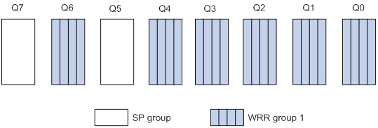
· Queue 7 has the highest priority. Its packets are sent preferentially.
· Queue 5 has the second highest priority. Packets in queue 5 are sent when queue 7 is empty.
· All other queues in WRR group 1 are scheduled according to their weights. When both queue 7 and queue 5 are empty, WRR group 1 is scheduled.
Configuration restrictions and guidelines
When you configure a queue scheduling profile, follow these restrictions and guidelines:
· Both Layer 2 and Layer 3 Ethernet interfaces support queue scheduling profiles. The term "interface" in this chapter collectively refers to these two types of interfaces. You can use the port link-mode command to configure an Ethernet port as a Layer 2 or Layer 3 interface (see Layer 2—LAN Switching Configuration Guide).
· Only one queue scheduling profile can be applied to an interface.
· You can modify the scheduling parameters in a queue scheduling profile already applied to an interface.
Configuring a queue scheduling profile for an interface
|
Step |
Command |
Remarks |
|
1. Enter system view. |
system-view |
N/A |
|
2. Create a queue scheduling profile and enter queue scheduling profile view. |
qos qmprofile profile-name |
By default, no queue scheduling profile exists. |
|
3. Configure queue scheduling parameters. |
·
Configure a queue to use SP: ·
Configure a queue to use WRR: ·
Configure a queue to use WFQ: |
By default, all queues in a queue scheduling profile are SP queues. One queue can use only one queue scheduling algorithm. In a queue scheduling profile, you can configure different queue scheduling algorithms for different queues. However, you cannot configure both WRR and WFQ in a queue scheduling profile. |
|
4. (Optional.) Set the minimum guaranteed bandwidth for a queue. |
bandwidth queue queue-id min bandwidth-value |
The default setting is 64 kbps. You can configure this command only for a WFQ queue. |
|
5. Return to system view. |
quit |
N/A |
|
6. Enter interface view. |
interface interface-type interface-number |
N/A |
|
7. Apply the queue scheduling profile to the interface. |
qos apply qmprofile profile-name |
By default, no queue scheduling profile is applied to an interface. |
Queue scheduling profile configuration example
Network requirements
Configure a queue scheduling profile to meet the following requirements on HundredGigE 1/0/1:
· Queue 7 has the highest priority, and its packets are sent preferentially.
· Queue 0 through queue 6 belong to the WRR group, with their weights as 2, 1, 2, 4, 6, 8, and 10, respectively. When queue 7 is empty, the WRR group is scheduled.
Configuration procedure
# Enter system view.
<Sysname> system-view
# Create a queue scheduling profile named qm1.
[Sysname] qos qmprofile qm1
[Sysname-qmprofile-qm1]
# Configure queue 7 to use SP queuing.
[Sysname-qmprofile-qm1] queue 7 sp
# Assign queue 0 through queue 6 to the WRR group, with their weights as 2, 1, 2, 4, 6, 8, and 10, respectively.
[Sysname-qmprofile-qm1] queue 0 wrr group 1 weight 2
[Sysname-qmprofile-qm1] queue 1 wrr group 1 weight 1
[Sysname-qmprofile-qm1] queue 2 wrr group 1 weight 2
[Sysname-qmprofile-qm1] queue 3 wrr group 1 weight 4
[Sysname-qmprofile-qm1] queue 4 wrr group 1 weight 6
[Sysname-qmprofile-qm1] queue 5 wrr group 1 weight 8
[Sysname-qmprofile-qm1] queue 6 wrr group 1 weight 10
[Sysname-qmprofile-qm1] quit
# Apply queue scheduling profile qm1 to HundredGigE 1/0/1.
[Sysname] interface hundredgige 1/0/1
[Sysname-HundredGigE1/0/1] qos apply qmprofile qm1
After the configuration is completed, HundredGigE 1/0/1 performs queue scheduling as specified in queue scheduling profile qm1.
Displaying and maintaining congestion management
Execute display commands in any view and reset commands in user view.
|
Task |
Command |
|
Display SP queuing configuration. |
display qos queue sp interface [ interface-type interface-number ] |
|
Display WRR queuing configuration. |
display qos queue wrr interface [ interface-type interface-number ] |
|
Display WFQ queuing configuration. |
display qos queue wfq interface [ interface-type interface-number ] |
|
(In standalone mode.) Display the configuration of queue scheduling profiles. |
display qos qmprofile configuration [ profile-name ] [ slot slot-number ] |
|
(In IRF mode.) Display the configuration of queue scheduling profiles. |
display qos qmprofile configuration [ profile-name ] [ chassis chassis-number slot slot-number ] |
|
Display the queue scheduling profiles applied to interfaces. |
display qos qmprofile interface [ interface-type interface-number ] |
Configuring congestion avoidance
Overview
Avoiding congestion before it occurs is a proactive approach to improving network performance. As a flow control mechanism, congestion avoidance:
· Actively monitors network resources (such as queues and memory buffers).
· Drops packets when congestion is expected to occur or deteriorate.
When dropping packets from a source end, congestion avoidance cooperates with the flow control mechanism at the source end to regulate the network traffic size. The combination of the local packet drop policy and the source-end flow control mechanism implements the following functions:
· Maximizes throughput and network use efficiency.
· Minimizes packet loss and delay.
Tail drop
Congestion management techniques drop all packets that are arriving at a full queue. This tail drop mechanism results in global TCP synchronization. If packets from multiple TCP connections are dropped, these TCP connections go into the state of congestion avoidance and slow start to reduce traffic. However, traffic peak occurs later. Consequently, the network traffic jitters all the time.
RED and WRED
You can use Random Early Detection (RED) or Weighted Random Early Detection (WRED) to avoid global TCP synchronization.
Both RED and WRED avoid global TCP synchronization by randomly dropping packets. When the sending rates of some TCP sessions slow down after their packets are dropped, other TCP sessions remain at high sending rates. Link bandwidth is efficiently used, because TCP sessions at high sending rates always exist.
The RED or WRED algorithm sets an upper threshold and lower threshold for each queue, and processes the packets in a queue as follows:
· When the queue size is shorter than the lower threshold, no packet is dropped.
· When the queue size reaches the upper threshold, all subsequent packets are dropped.
· When the queue size is between the lower threshold and the upper threshold, the received packets are dropped at random. The drop probability in a queue increases along with the queue size under the maximum drop probability.
If the current queue size is compared with the upper threshold and lower threshold to determine the drop policy, burst traffic is not fairly treated. To solve this problem, WRED compares the average queue size with the upper threshold and lower threshold to determine the drop probability.
The average queue size reflects the queue size change trend but is not sensitive to burst queue size changes, and burst traffic can be fairly treated.
When WFQ queuing is used, you can set the following parameters for packets with different precedence values to provide differentiated drop policies:
· Exponent for average queue size calculation.
· Upper threshold.
· Lower threshold.
· Drop probability.
Relationship between WRED and queuing mechanisms
Figure 19 Relationship between WRED and queuing mechanisms
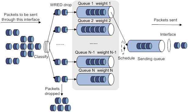
· A flow with a smaller queue size has a lower packet drop probability.
· A flow with a larger queue size has a higher packet drop probability.
In this way, the benefits of the flow with a smaller queue size are protected.
Configuring and applying a queue-based WRED table
The switch supports queue-based WRED tables. You can configure separate drop parameters for different queues. When congestion occurs, packets of a queue are randomly dropped based on the drop parameters of the queue.
Determine the following parameters before configuring WRED:
· Upper threshold and lower threshold—When the average queue size is smaller than the lower threshold, packets are not dropped. When the average queue size is between the lower threshold and the upper threshold, the packets are dropped at random. The longer the queue, the higher the drop probability. When the average queue size exceeds the upper threshold, subsequent packets are dropped.
· Drop precedence—A parameter used for packet drop. The value 0 corresponds to green packets, the value 1 corresponds to yellow packets, and the value 2 corresponds to red packets. Red packets are dropped preferentially.
· Exponent for average queue size calculation—The greater the exponent, the less sensitive the average queue size is to real-time queue size changes. The formula for calculating the average queue size is:
Average queue size = ( previous average queue size x (1 – 2–n) ) + (current queue size x 2–n), where n is the exponent.
Configuration procedure
By using a queue-based WRED table, WRED randomly drops packets during congestion based on the queues that hold packets.
Both Layer 2 and Layer 3 Ethernet interfaces support WRED tables. The term "interface" in this section collectively refers to these two types of interfaces. You can use the port link-mode command to configure an Ethernet port as a Layer 2 or Layer 3 interface (see Layer 2—LAN Switching Configuration Guide).
To configure and apply a queue-based WRED table:
|
Step |
Command |
Remarks |
|
1. Enter system view. |
system-view |
N/A |
|
2. Create a WRED table and enter its view. |
qos wred queue table table-name |
N/A |
|
3. (Optional.) Set the WRED exponent for average queue size calculation. |
queue queue-id weighting-constant exponent |
The default setting is 9. |
|
4. (Optional.) Configure the other WRED parameters. |
queue queue-id [ drop-level drop-level ] low-limit low-limit high-limit high-limit [ discard-probability discard-prob ] |
By default, the lower limit is 100, the upper limit is 1000, and the drop probability is 10%. |
|
5. Return to system view. |
quit |
N/A |
|
6. Enter interface view. |
interface interface-type interface-number |
N/A |
|
7. Apply the WRED table to the interface. |
qos wred apply [ table-name ] |
By default, no WRED table is applied to an interface, and the tail drop is used on an interface. |
Configuration example
Network requirements
Apply a WRED table to HundredGigE 1/0/2, so that the packets are dropped as follows when congestion occurs:
· For the interface to preferentially forward higher-priority traffic, set a lower drop probability for a queue with a greater queue number. Set different drop parameters for queue 0, queue 3, and queue 7.
· Drop packets according to their colors.
? In queue 0, set the drop probability to 25%, 50%, and 75% for green, yellow, and red packets, respectively.
? In queue 3, set the drop probability to 5%, 10%, and 25% for green, yellow, and red packets, respectively.
? In queue 7, set the drop probability to 1%, 5%, and 10% for green, yellow, and red packets, respectively.
Configuration procedure
# Configure a queue-based WRED table, and set different drop parameters for packets with different drop levels in different queues.
<Sysname> system-view
[Sysname] qos wred queue table queue-table1
[Sysname-wred-table-queue-table1] queue 0 drop-level 0 low-limit 128 high-limit 512 discard-probability 25
[Sysname-wred-table-queue-table1] queue 0 drop-level 1 low-limit 128 high-limit 512 discard-probability 50
[Sysname-wred-table-queue-table1] queue 0 drop-level 2 low-limit 128 high-limit 512 discard-probability 75
[Sysname-wred-table-queue-table1] queue 3 drop-level 0 low-limit 256 high-limit 640 discard-probability 5
[Sysname-wred-table-queue-table1] queue 3 drop-level 1 low-limit 256 high-limit 640 discard-probability 10
[Sysname-wred-table-queue-table1] queue 3 drop-level 2 low-limit 256 high-limit 640 discard-probability 25
[Sysname-wred-table-queue-table1] queue 7 drop-level 0 low-limit 512 high-limit 1024 discard-probability 1
[Sysname-wred-table-queue-table1] queue 7 drop-level 1 low-limit 512 high-limit 1024 discard-probability 5
[Sysname-wred-table-queue-table1] queue 7 drop-level 2 low-limit 512 high-limit 1024 discard-probability 10
[Sysname-wred-table-queue-table1] quit
# Apply the queue-based WRED table to HundredGigE 1/0/2.
[Sysname] interface hundredgige 1/0/2
[Sysname-HundredGigE1/0/2] qos wred apply queue-table1
[Sysname-HundredGigE1/0/2] quit
Displaying and maintaining WRED
Execute display commands in any view.
|
Task |
Command |
|
Display WRED configuration and statistics for an interface. |
display qos wred interface [ interface-type interface-number |
|
(In standalone mode.) Display the configuration of a WRED table or all WRED tables. |
display qos wred table [ name table-name ] [ slot slot-number ] |
|
(In IRF mode.) Display the configuration of a WRED table or all WRED tables. |
display qos wred table [ name table-name ] [ chassis chassis-number slot slot-number ] |
Configuring traffic filtering
You can filter in or filter out traffic of a class by associating the class with a traffic filtering action. For example, you can filter packets sourced from an IP address according to network status.
Configuration procedure
To configure traffic filtering:
|
Step |
Command |
Remarks |
|
1. Enter system view. |
system-view |
N/A |
|
2. Create a traffic class and enter traffic class view. |
traffic classifier classifier-name [ operator { and | or } ] |
By default, no traffic classes exist. |
|
3. Configure a match criterion. |
if-match match-criteria |
By default, no match criterion is configured. |
|
4. Return to system view. |
quit |
N/A |
|
5. Create a traffic behavior and enter traffic behavior view. |
traffic behavior behavior-name |
By default, no traffic behaviors exist. |
|
6. Configure the traffic filtering action. |
filter { deny | permit } |
By default, no traffic filtering action is configured. |
|
7. Return to system view. |
quit |
N/A |
|
8. Create a QoS policy and enter QoS policy view. |
qos policy policy-name |
By default, no QoS policies exist. |
|
9. Associate the traffic class with the traffic behavior in the QoS policy. |
classifier classifier-name behavior behavior-name [ mode dcbx | insert-before before-classifier-name ] |
By default, a traffic class is not associated with a traffic behavior. The mode dcbx keyword specifies that a class-behavior association applies only to DCBX. For more information about DCBX, see Layer 2—LAN Switching Configuration Guide. |
|
10. Return to system view. |
quit |
N/A |
|
11. Apply the QoS policy. |
· Applying the QoS policy to an interface · Applying the QoS policy to VLANs · Applying the QoS policy globally · Applying the QoS policy to a control plane |
Choose one of the application destinations as needed. By default, no QoS policy is applied. |
|
12. (Optional.) Display the traffic filtering configuration. |
display traffic behavior user-defined [ behavior-name ] |
Available in any view. |
Configuration example
Network requirements
As shown in Figure 20, configure traffic filtering on HundredGigE 1/0/1 to deny the incoming packets with a source port number other than 21.
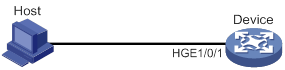
Configuration procedure
# Create advanced ACL 3000, and configure a rule to match packets whose source port number is not 21.
<Device> system-view
[Device] acl advanced 3000
[Device-acl-ipv4-adv-3000] rule 0 permit tcp source-port neq 21
[Device-acl-ipv4-adv-3000] quit
# Create a traffic class named classifier_1, and use ACL 3000 as the match criterion in the traffic class.
[Device] traffic classifier classifier_1
[Device-classifier-classifier_1] if-match acl 3000
[Device-classifier-classifier_1] quit
# Create a traffic behavior named behavior_1, and configure the traffic filtering action to drop packets.
[Device] traffic behavior behavior_1
[Device-behavior-behavior_1] filter deny
[Device-behavior-behavior_1] quit
# Create a QoS policy named policy, and associate traffic class classifier_1 with traffic behavior behavior_1 in the QoS policy.
[Device] qos policy policy
[Device-qospolicy-policy] classifier classifier_1 behavior behavior_1
[Device-qospolicy-policy] quit
# Apply QoS policy policy to the incoming traffic of HundredGigE 1/0/1.
[Device] interface hundredgige 1/0/1
[Device-HundredGigE1/0/1] qos apply policy policy inbound
Configuring protocol packet rate limiting
Configuration procedure
To configure protocol packet rate limiting:
|
Step |
Command |
Remarks |
|
1. Enter system view. |
system-view |
N/A |
|
2. Create a traffic class and enter traffic class view. |
traffic classifier classifier-name [ operator { and | or } ] |
By default, no traffic classes exist. |
|
3. Configure a match criterion. |
· if-match control-plane protocol protocol-name&<1-8> · if-match control-plane protocol-group protocol-group-name |
Use either command. By default, no match criteria are configured. For more information, see the if-match command in ACL and QoS Command Reference. |
|
4. Return to system view. |
quit |
N/A |
|
5. Create a traffic behavior and enter traffic behavior view. |
traffic behavior behavior-name |
By default, no traffic behaviors exist. |
|
6. Configure protocol packet rate limiting. |
packet-rate value |
By default, protocol packet rate limiting is not configured. |
|
7. Return to system view. |
quit |
N/A |
|
8. Create a QoS policy and enter QoS policy view. |
qos policy policy-name |
By default, no QoS policies exist. |
|
9. Associate the class with the traffic behavior in the QoS policy. |
classifier classifier-name behavior behavior-name [ mode dcbx | insert-before before-classifier-name ] |
By default, a class is not associated with any behavior. The mode dcbx keyword specifies that a class-behavior association applies only to DCBX. For more information about DCBX, see Layer 2—LAN Switching Configuration Guide. |
|
10. Return to system view. |
quit |
N/A |
|
11. Apply the QoS policy to a control plane. |
By default, no QoS policy is applied to a control plane. |
|
|
12. (Optional.) Display the protocol packet rate limiting configuration. |
display traffic behavior user-defined [ behavior-name ] |
Available in any view. |
Configuration example
Network requirements
As shown in Figure 21, limit the rate of DHCP protocol packets sent to the CPU of the device to 500 pps.
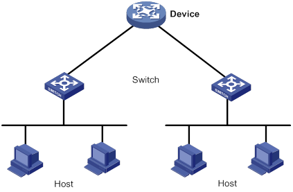
Configuration procedures
# Create a traffic class named classifier_1, and configure the class to match DHCP protocol packets.
<Device> system-view
[Device] traffic classifier classifier_1
[Device-classifier-classifier_1] if-match control-plane protocol dhcp
[Device-classifier-classifier_1] quit
# Create a traffic behavior named behavior_1, and configure the behavior to limit the packet rate to 500 pps.
[Device] traffic behavior behavior_1
[Device-behavior-behavior_1] packet-rate 500
[Device-behavior-behavior_1] quit
# Create a QoS policy named policy, and associate class classifier_1 with behavior behavior_1 in the policy.
[Device] qos policy policy
[Device-qospolicy-policy] classifier classifier_1 behavior behavior_1
[Device-qospolicy-policy] quit
# Apply QoS policy policy to the control plane.
[Device] control-plane
[Device-cp] qos apply policy policy inbound
Configuring priority marking
Priority marking sets the priority fields or flag bits of packets to modify the priority of packets. For example, you can use priority marking to set IP precedence or DSCP for a class of IP packets to control the forwarding of these packets.
1. Configure a traffic behavior with a priority marking action.
2. Associate the traffic class with the traffic behavior.
Priority marking can be used together with priority mapping. For more information, see "Configuring priority mapping."
Restrictions and guidelines
Marking different priority types has different impacts on QoS scheduling. For more information, see Figure 5.
Configuration procedure
To configure priority marking:
|
Step |
Command |
Remarks |
|
1. Enter system view. |
system-view |
N/A |
|
2. Create a traffic class and enter traffic class view. |
traffic classifier classifier-name [ operator { and | or } ] |
By default, no traffic classes exist. |
|
3. Configure a match criterion. |
if-match match-criteria |
By default, no match criterion is configured. For more information about the if-match command, see ACL and QoS Command Reference. |
|
4. Return to system view. |
quit |
N/A |
|
5. Create a traffic behavior and enter traffic behavior view. |
traffic behavior behavior-name |
By default, no traffic behaviors exist. |
|
6. Configure a priority marking action. |
·
Set the DSCP value for packets: ·
Set the 802.1p priority for packets: ·
Set the IP precedence for packets: ·
Set the local precedence for packets: ·
Set the local QoS ID for packets: ·
Set the SVLAN for packets: |
Use one of the commands. By default, no priority marking action is configured. The remark drop-precedence command applies only to the incoming traffic. |
|
7. Return to system view. |
quit |
N/A |
|
8. Create a QoS policy and enter QoS policy view. |
qos policy policy-name |
By default, no QoS policies exist. |
|
9. Associate the traffic class with the traffic behavior in the QoS policy. |
classifier classifier-name behavior behavior-name [ mode dcbx | insert-before before-classifier-name ] |
By default, a traffic class is not associated with a traffic behavior. The mode dcbx keyword specifies that a class-behavior association applies only to DCBX. For more information about DCBX, see Layer 2—LAN Switching Configuration Guide. |
|
10. Return to system view. |
quit |
N/A |
|
11. Apply the QoS policy. |
· Applying the QoS policy to an interface · Applying the QoS policy to VLANs · Applying the QoS policy globally · Applying the QoS policy to a control plane |
Choose one of the application destinations as needed. By default, no QoS policy is applied. |
|
12. (Optional.) Display the priority marking configuration. |
display traffic behavior user-defined [ behavior-name ] |
Available in any view. |
Configuration example
Network requirements
As shown in Figure 22, configure priority marking on the device to meet the following requirements:
|
Traffic source |
Destination |
Processing priority |
|
Host A, B |
Data server |
High |
|
Host A, B |
Mail server |
Medium |
|
Host A, B |
File server |
Low |
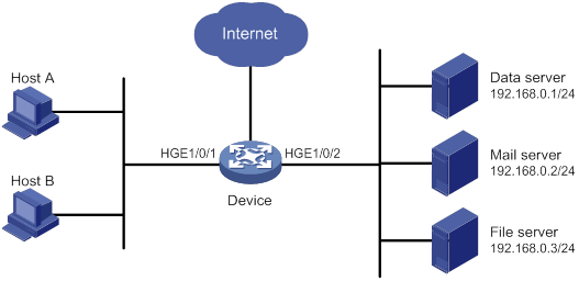
Configuration procedure
# Create advanced ACL 3000, and configure a rule to match packets with destination IP address 192.168.0.1.
<Device> system-view
[Device] acl advanced 3000
[Device-acl-ipv4-adv-3000] rule permit ip destination 192.168.0.1 0
[Device-acl-ipv4-adv-3000] quit
# Create advanced ACL 3001, and configure a rule to match packets with destination IP address 192.168.0.2.
[Device] acl advanced 3001
[Device-acl-ipv4-adv-3001] rule permit ip destination 192.168.0.2 0
[Device-acl-ipv4-adv-3001] quit
# Create advanced ACL 3002, and configure a rule to match packets with destination IP address 192.168.0.3.
[Device] acl advanced 3002
[Device-acl-ipv4-adv-3002] rule permit ip destination 192.168.0.3 0
[Device-acl-ipv4-adv-3002] quit
# Create a traffic class named classifier_dbserver, and use ACL 3000 as the match criterion in the traffic class.
[Device] traffic classifier classifier_dbserver
[Device-classifier-classifier_dbserver] if-match acl 3000
[Device-classifier-classifier_dbserver] quit
# Create a traffic class named classifier_mserver, and use ACL 3001 as the match criterion in the traffic class.
[Device] traffic classifier classifier_mserver
[Device-classifier-classifier_mserver] if-match acl 3001
[Device-classifier-classifier_mserver] quit
# Create a traffic class named classifier_fserver, and use ACL 3002 as the match criterion in the traffic class.
[Device] traffic classifier classifier_fserver
[Device-classifier-classifier_fserver] if-match acl 3002
[Device-classifier-classifier_fserver] quit
# Create a traffic behavior named behavior_dbserver, and configure the action of setting the local precedence value to 4.
[Device] traffic behavior behavior_dbserver
[Device-behavior-behavior_dbserver] remark local-precedence 4
[Device-behavior-behavior_dbserver] quit
# Create a traffic behavior named behavior_mserver, and configure the action of setting the local precedence value to 3.
[Device] traffic behavior behavior_mserver
[Device-behavior-behavior_mserver] remark local-precedence 3
[Device-behavior-behavior_mserver] quit
# Create a traffic behavior named behavior_fserver, and configure the action of setting the local precedence value to 2.
[Device] traffic behavior behavior_fserver
[Device-behavior-behavior_fserver] remark local-precedence 2
[Device-behavior-behavior_fserver] quit
# Create a QoS policy named policy_server, and associate traffic classes with traffic behaviors in the QoS policy.
[Device] qos policy policy_server
[Device-qospolicy-policy_server] classifier classifier_dbserver behavior behavior_dbserver
[Device-qospolicy-policy_server] classifier classifier_mserver behavior behavior_mserver
[Device-qospolicy-policy_server] classifier classifier_fserver behavior behavior_fserver
[Device-qospolicy-policy_server] quit
# Apply QoS policy policy_server to the incoming traffic of HundredGigE 1/0/1.
[Device] interface hundredgige 1/0/1
[Device-HundredGigE1/0/1] qos apply policy policy_server inbound
[Device-HundredGigE1/0/1] quit
Configuring nesting
Nesting adds a VLAN tag to the matching packets to allow the VLAN-tagged packets to pass through the corresponding VLAN. For example, you can add an outer VLAN tag to packets from a customer network to a service provider network. This allows the packets to pass through the service provider network by carrying a VLAN tag assigned by the service provider.
Configuration procedure
To configure nesting:
|
Step |
Command |
Remarks |
|
1. Enter system view. |
system-view |
N/A |
|
2. Create a traffic class and enter traffic class view. |
traffic classifier classifier-name [ operator { and | or } ] |
By default, no traffic classes exist. |
|
3. Configure a match criterion. |
if-match match-criteria |
By default, no match criterion is configured for a traffic class. For more information about the match criteria, see the if-match command in ACL and QoS Command Reference. |
|
4. Return to system view. |
quit |
N/A |
|
5. Create a traffic behavior and enter traffic behavior view. |
traffic behavior behavior-name |
By default, no traffic behaviors exist. |
|
6. Configure a VLAN tag adding action. |
nest top-most vlan vlan-id |
By default, no VLAN tag adding action is configured for a traffic behavior. |
|
7. Return to system view. |
quit |
N/A |
|
8. Create a QoS policy and enter QoS policy view. |
qos policy policy-name |
By default, no QoS policies exist. |
|
9. Associate the traffic class with the traffic behavior in the QoS policy. |
classifier classifier-name behavior behavior-name [ mode dcbx | insert-before before-classifier-name ] |
By default, a traffic class is not associated with a traffic behavior. The mode dcbx keyword specifies that a class-behavior association applies only to DCBX. For more information about DCBX, see Layer 2—LAN Switching Configuration Guide. |
|
10. Return to system view. |
quit |
N/A |
|
11. Apply the QoS policy. |
· Applying the QoS policy to an interface · Applying the QoS policy to VLANs · Applying the QoS policy globally · Applying the QoS policy to a control plane |
Choose one of the application destinations as needed. By default, no QoS policy is applied. |
Configuration example
Network requirements
As shown in Figure 23:
· Site 1 and Site 2 in VPN A are two branches of a company. They use VLAN 5 to transmit traffic.
· Because Site 1 and Site 2 are located in different areas, the two sites use the VPN access service of a service provider. The service provider assigns VLAN 100 to the two sites.
Configure nesting, so that the two branches can communicate through the service provider network.
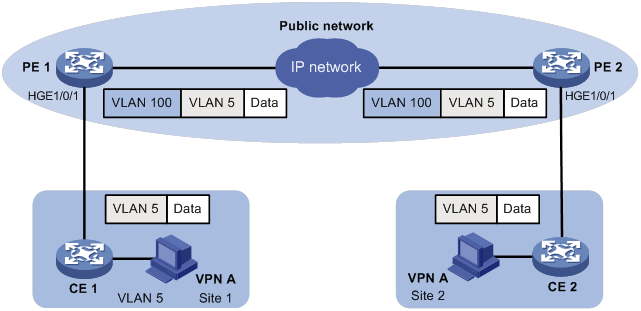
Configuration procedure
Configuring PE 1
# Create a traffic class named test to match traffic with VLAN ID 5.
<PE1> system-view
[PE1] traffic classifier test
[PE1-classifier-test] if-match service-vlan-id 5
[PE1-classifier-test] quit
# Configure an action to add outer VLAN tag 100 in traffic behavior test.
[PE1] traffic behavior test
[PE1-behavior-test] nest top-most vlan 100
[PE1-behavior-test] quit
# Create a QoS policy named test, and associate class test with behavior test in the QoS policy.
[PE1] qos policy test
[PE1-qospolicy-test] classifier test behavior test
[PE1-qospolicy-test] quit
# Configure the downlink port (HundredGigE 1/0/1) as a hybrid port, and assign the port to VLAN 100 as an untagged member.
[PE1] interface hundredgige 1/0/1
[PE1-HundredGigE1/0/1] port link-type hybrid
[PE1-HundredGigE1/0/1] port hybrid vlan 100 untagged
# Apply QoS policy test to the incoming traffic of HundredGigE 1/0/1.
[PE1-HundredGigE1/0/1] qos apply policy test inbound
[PE1-HundredGigE1/0/1] quit
# Configure the uplink port (HundredGigE 1/0/2) as a trunk port, and assign it to VLAN 100.
[PE1] interface hundredgige 1/0/2
[PE1-HundredGigE1/0/2] port link-type trunk
[PE1-HundredGigE1/0/2] port trunk permit vlan 100
[PE1-HundredGigE1/0/2] quit
Configuring PE 2
Configure PE 2 in the same way PE 1 is configured.
Configuring traffic redirecting
Traffic redirecting redirects packets matching the specified match criteria to a location for processing.
You can redirect packets to an interface or the CPU.
Configuration procedure
To configure traffic redirecting:
|
Step |
Command |
Remarks |
|
1. Enter system view. |
system-view |
N/A |
|
2. Create a traffic class and enter traffic class view. |
traffic classifier classifier-name [ operator { and | or } ] |
By default, no traffic classes exist. |
|
3. Configure a match criterion. |
if-match match-criteria |
By default, no match criterion is configured for a traffic class. For more information about the match criteria, see the if-match command in ACL and QoS Command Reference. |
|
4. Return to system view. |
quit |
N/A |
|
5. Create a traffic behavior and enter traffic behavior view. |
traffic behavior behavior-name |
By default, no traffic behaviors exist. |
|
6. Configure a traffic redirecting action. |
redirect { cpu | interface interface-type interface-number } |
By default, no traffic redirecting action is configured for a traffic behavior. If you execute this command multiple times, the most recent configuration takes effect. For traffic redirecting to an Ethernet interface on an interface module, the switch does not display the redirecting action after the interface module is removed. After the interface module is reinserted, the switch can display the redirecting action. |
|
7. Return to system view. |
quit |
N/A |
|
8. Create a QoS policy and enter QoS policy view. |
qos policy policy-name |
By default, no QoS policies exist. |
|
9. Associate the traffic class with the traffic behavior in the QoS policy. |
classifier classifier-name behavior behavior-name [ mode dcbx | insert-before before-classifier-name ] |
By default, a traffic class is not associated with a traffic behavior. The mode dcbx keyword specifies that a class-behavior association applies only to DCBX. For more information about DCBX, see Layer 2—LAN Switching Configuration Guide. |
|
10. Return to system view. |
quit |
N/A |
|
11. Apply the QoS policy. |
· Applying the QoS policy to an interface · Applying the QoS policy to VLANs · Applying the QoS policy globally · Applying the QoS policy to a control plane |
Choose one of the application destinations as needed. By default, no QoS policy is applied. A traffic redirecting action can take effect only when the QoS policy is applied to the inbound direction. |
|
12. (Optional.) Display traffic redirecting configuration. |
display traffic behavior user-defined [ behavior-name ] |
Available in any view. |
Configuration example
Network requirements
As shown in Figure 24:
· Device A is connected to Device B through two links. Device A and Device B are each connected to other devices.
· HundredGigE 1/0/2 of Device A and HundredGigE 1/0/2 of Device B belong to VLAN 200.
· HundredGigE 1/0/3 of Device A and HundredGigE 1/0/3 of Device B belong to VLAN 201.
· On Device A, the IP address of VLAN-interface 200 is 200.1.1.1/24, and that of VLAN-interface 201 is 201.1.1.1/24.
· On Device B, the IP address of VLAN-interface 200 is 200.1.1.2/24, and that of VLAN-interface 201 is 201.1.1.2/24.
Configure the actions of redirecting traffic to an interface to meet the following requirements:
· Packets with source IP address 2.1.1.1 received on HundredGigE 1/0/1 of Device A are forwarded to HundredGigE 1/0/2.
· Packets with source IP address 2.1.1.2 received on HundredGigE 1/0/1 of Device A are forwarded to HundredGigE 1/0/3.
· Other packets received on HundredGigE 1/0/1 of Device A are forwarded according to the routing table.
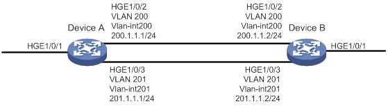
Configuration procedure
# Create basic ACL 2000, and configure a rule to match packets with source IP address 2.1.1.1.
<DeviceA> system-view
[DeviceA] acl basic 2000
[DeviceA-acl-ipv4-basic-2000] rule permit source 2.1.1.1 0
[DeviceA-acl-ipv4-basic-2000] quit
# Create basic ACL 2001, and configure a rule to match packets with source IP address 2.1.1.2.
[DeviceA] acl basic 2001
[DeviceA-acl-ipv4-basic-2001] rule permit source 2.1.1.2 0
[DeviceA-acl-ipv4-basic-2001] quit
# Create a traffic class named classifier_1, and use ACL 2000 as the match criterion in the traffic class.
[DeviceA] traffic classifier classifier_1
[DeviceA-classifier-classifier_1] if-match acl 2000
[DeviceA-classifier-classifier_1] quit
# Create a traffic class named classifier_2, and use ACL 2001 as the match criterion in the traffic class.
[DeviceA] traffic classifier classifier_2
[DeviceA-classifier-classifier_2] if-match acl 2001
[DeviceA-classifier-classifier_2] quit
# Create a traffic behavior named behavior_1, and configure the action of redirecting traffic to HundredGigE 1/0/2.
[DeviceA] traffic behavior behavior_1
[DeviceA-behavior-behavior_1] redirect interface hundredgige 1/0/2
[DeviceA-behavior-behavior_1] quit
# Create a traffic behavior named behavior_2, and configure the action of redirecting traffic to HundredGigE 1/0/3.
[DeviceA] traffic behavior behavior_2
[DeviceA-behavior-behavior_2] redirect interface hundredgige 1/0/3
[DeviceA-behavior-behavior_2] quit
# Create a QoS policy named policy.
[DeviceA] qos policy policy
# Associate traffic class classifier_1 with traffic behavior behavior_1 in the QoS policy.
[DeviceA-qospolicy-policy] classifier classifier_1 behavior behavior_1
# Associate traffic class classifier_2 with traffic behavior behavior_2 in the QoS policy.
[DeviceA-qospolicy-policy] classifier classifier_2 behavior behavior_2
[DeviceA-qospolicy-policy] quit
# Apply QoS policy policy to the incoming traffic of HundredGigE 1/0/1.
[DeviceA] interface hundredgige 1/0/1
[DeviceA-HundredGigE1/0/1] qos apply policy policy inbound
Configuring global CAR
Overview
Global committed access rate (CAR) is an approach to policing traffic flows globally. It adds flexibility to common CAR where traffic policing is performed only on a per-traffic class or per-interface basis. In this approach, CAR actions are created in system view and each can be used to police multiple traffic flows as a whole.
Global CAR provides the following CAR actions: aggregate CAR and hierarchical CAR. Only aggregate CAR is supported in the current software version.
Aggregate CAR
An aggregate CAR action is created globally. It can be directly applied to interfaces or used in the traffic behaviors associated with different traffic classes to police multiple traffic flows as a whole. The total rate of the traffic flows must conform to the traffic policing specifications set in the aggregate CAR action.
Hierarchical CAR
A hierarchical CAR action is created globally. It must be used in conjunction with a common CAR or aggregate CAR action. With a hierarchical CAR action, you can limit the total traffic of multiple traffic classes.
A hierarchical CAR action can be used in the common or aggregate CAR action for a traffic class in either AND mode or OR mode.
· In AND mode, the rate of the traffic class is strictly limited under the common or aggregate CAR. This mode applies to flows that must be strictly rate limited.
· In OR mode, the traffic class can use idle bandwidth of other traffic classes associated with the hierarchical CAR. This mode applies to high priority, bursty traffic like video.
By using the two modes appropriately, you can improve bandwidth efficiency.
For example, suppose two flows exist: a low priority data flow and a high priority, bursty video flow. Their total traffic rate cannot exceed 4096 kbps and the video flow must be assured of at least 2048 kbps bandwidth. You can perform the following tasks:
· Configure common CAR actions to set the traffic rate to 2048 kbps for the two flows.
· Configure a hierarchical CAR action to limit their total traffic rate to 4096 kbps.
· Use the action in AND mode in the common CAR action for the data flow.
· Use the action in OR mode in the common CAR action for the video flow.
The video flow is assured of 2048 kbps bandwidth and can use idle bandwidth of the data flow.
In a bandwidth oversubscription scenario, the uplink port bandwidth is lower than the total downlink port traffic rate. You can use hierarchical CAR to meet the following requirements:
· Limit the total rate of downlink port traffic.
· Allow each downlink port to forward traffic at the maximum rate when the other ports are idle.
For example, you can perform the following tasks:
· Use common CAR actions to limit the rates of Internet access flow 1 and flow 2 to both 128 kbps.
· Use a hierarchical CAR action to limit their total traffic rate to 192 kbps.
· Use the hierarchical CAR action for both flow 1 and flow 2 in AND mode.
When flow 1 is not present, flow 2 is transmitted at the maximum rate, 128 kbps. When both flows are present, the total rate of the two flows cannot exceed 192 kbps. As a result, the traffic rate of flow 2 might drop below 128 kbps.
Configuring aggregate CAR by using the MQC approach
|
Step |
Command |
Remarks |
|
1. Enter system view. |
system-view |
N/A |
|
2. Create a traffic class and enter traffic class view. |
traffic classifier classifier-name [ operator { and | or } ] |
By default, no traffic classes exist. |
|
3. Configure a match criterion. |
if-match match-criteria |
By default, no match criterion is configured for a traffic class. For more information about the match criteria, see the if-match command in ACL and QoS Command Reference. |
|
4. Return to system view. |
quit |
N/A |
|
5. Configure an aggregate CAR action. |
qos car car-name aggregative cir committed-information-rate [ cbs committed-burst-size [ ebs excess-burst-size ] ] qos car car-name aggregative cir committed-information-rate [ cbs committed-burst-size ] pir peak-information-rate [ ebs excess-burst-size ] |
By default, no aggregate CAR action is configured. |
|
6. Enter traffic behavior view. |
traffic behavior behavior-name |
N/A |
|
7. Use the aggregate CAR in the traffic behavior. |
car name car-name |
By default, no aggregate CAR action is used in a traffic behavior. |
|
8. Return to system view. |
quit |
N/A |
|
9. Create a QoS policy and enter QoS policy view. |
qos policy policy-name |
By default, no QoS policies exist. |
|
10. Associate the traffic class with the traffic behavior in the QoS policy. |
classifier classifier-name behavior behavior-name [ mode dcbx | insert-before before-classifier-name ] |
By default, a traffic class is not associated with a traffic behavior. |
|
11. Return to system view. |
quit |
N/A |
|
12. Apply the QoS policy. |
· Applying the QoS policy to an interface · Applying the QoS policy to VLANs · Applying the QoS policy globally · Applying the QoS policy to a control plane |
Choose one of the application destinations as needed. By default, no QoS policy is applied. An aggregate CAR action takes effect only when the QoS policy is applied to the inbound direction. |
Displaying and maintaining global CAR
Execute display commands in any view and reset commands in user view.
|
Task |
Command |
|
Display statistics for global CAR actions. |
display qos car name [ car-name ] |
|
Clear statistics for global CAR actions. |
reset qos car name [ car-name ] |
Configuring class-based accounting
Configuration procedure
To configure class-based accounting:
|
Step |
Command |
Remarks |
|
1. Enter system view. |
system-view |
N/A |
|
2. Create a traffic class and enter traffic class view. |
traffic classifier classifier-name [ operator { and | or } ] |
By default, no traffic classes exist. |
|
3. Configure a match criterion. |
if-match match-criteria |
By default, no match criterion is configured. For more information about the if-match command, see ACL and QoS Command Reference. |
|
4. Return to system view. |
quit |
N/A |
|
5. Create a traffic behavior and enter traffic behavior view. |
traffic behavior behavior-name |
By default, no traffic behaviors exist. |
|
6. Configure an accounting action. |
accounting [ byte | packet ] |
By default, no traffic accounting action is configured. If you do not specify the byte or packet keyword, the switch counts traffic in packets. |
|
7. Return to system view. |
quit |
N/A |
|
8. Create a QoS policy and enter QoS policy view. |
qos policy policy-name |
By default, no QoS policies exist. |
|
9. Associate the traffic class with the traffic behavior in the QoS policy. |
classifier classifier-name behavior behavior-name [ mode dcbx | insert-before before-classifier-name ] |
By default, a traffic class is not associated with a traffic behavior. The mode dcbx keyword specifies that a class-behavior association applies only to DCBX. For more information about DCBX, see Layer 2—LAN Switching Configuration Guide. |
|
10. Return to system view. |
quit |
N/A |
|
11. Apply the QoS policy. |
· Applying the QoS policy to an interface · Applying the QoS policy to VLANs · Applying the QoS policy to a control plane |
Choose one of the application destinations as needed. By default, no QoS policy is applied. |
|
12. Display traffic accounting configuration. |
In standalone mode: · display qos policy control-plane slot slot-number · display qos policy interface [ interface-type interface-number ] [ inbound | outbound ] · display qos vlan-policy { name policy-name | vlan [ vlan-id ] } [ slot slot-number ] [ inbound | outbound ] In IRF mode: · display qos policy control-plane chassis chassis-number slot slot-number · display qos policy interface [ interface-type interface-number ] [ chassis chassis-number slot slot-number ] [ inbound | outbound ] · display qos vlan-policy { name policy-name | vlan [ vlan-id ] } [ chassis chassis-number slot slot-number ] [ inbound | outbound ] |
Available in any view. |
Configuration example
Network requirements
As shown in Figure 25, configure class-based accounting on HundredGigE 1/0/1 to collect statistics for incoming traffic from 1.1.1.1/24.
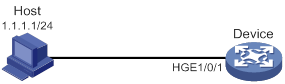
Configuration procedure
# Create basic ACL 2000, and configure a rule to match packets with source IP address 1.1.1.1.
<Device> system-view
[Device] acl basic 2000
[Device-acl-ipv4-basic-2000] rule permit source 1.1.1.1 0
[Device-acl-ipv4-basic-2000] quit
# Create a traffic class named classifier_1, and use ACL 2000 as the match criterion in the traffic class.
[Device] traffic classifier classifier_1
[Device-classifier-classifier_1] if-match acl 2000
[Device-classifier-classifier_1] quit
# Create a traffic behavior named behavior_1, and configure the class-based accounting action.
[Device] traffic behavior behavior_1
[Device-behavior-behavior_1] accounting packet
[Device-behavior-behavior_1] quit
# Create a QoS policy named policy, and associate traffic class classifier_1 with traffic behavior behavior_1 in the QoS policy.
[Device] qos policy policy
[Device-qospolicy-policy] classifier classifier_1 behavior behavior_1
[Device-qospolicy-policy] quit
# Apply QoS policy policy to the incoming traffic of HundredGigE 1/0/1.
[Device] interface hundredgige 1/0/1
[Device-HundredGigE1/0/1] qos apply policy policy inbound
[Device-HundredGigE1/0/1] quit
# Display traffic statistics to verify the configuration.
[Device] display qos policy interface hundredgige 1/0/1
Interface: HundredGigE1/0/1
Direction: Inbound
Policy: policy
Classifier: classifier_1
Operator: AND
Rule(s) :
If-match acl 2000
Behavior: behavior_1
Accounting enable:
28529 (Packets)
Configuring queue-based accounting
Queue-based accounting collects statistics for each interface on a per-queue basis, such as:
· The total length of a queue.
· Its current length.
· The total number of packets forwarded.
· The number of per-color packets forwarded.
Configuration procedure
To configure queue-based accounting:
|
Step |
Command |
Description |
|
1. Enter system view. |
system-view |
N/A |
|
2. Set the packet counting mode to queue. |
statistic mode queue |
The default setting is vsi. |
Displaying and maintaining queue-based accounting
Execute display commands in any view and reset commands in user view.
|
Task |
Command |
|
Display statistics collected by the queue-based accounting feature. |
display qos queue-statistics interface [ interface-type interface-number ] outbound |
|
Display the packet counting mode. |
display statistic mode |
|
Clear queue-based traffic statistics (see Interface Command Reference). |
reset counters interface [ interface-type [ interface-number | interface-number.subnumber ] ] |
Appendixes
Appendix A Acronym
Table 3 Appendix A Acronym
|
Acronym |
Full spelling |
|
BE |
Best Effort |
|
CAR |
Committed Access Rate |
|
CBS |
Committed Burst Size |
|
CIR |
Committed Information Rate |
|
DCBX |
Data Center Bridging Exchange Protocol |
|
DiffServ |
Differentiated Service |
|
DSCP |
Differentiated Services Code Point |
|
EBS |
Excess Burst Size |
|
FIFO |
First in First out |
|
FQ |
Fair Queuing |
|
GTS |
Generic Traffic Shaping |
|
IntServ |
Integrated Service |
|
ISP |
Internet Service Provider |
|
MPLS |
Multiprotocol Label Switching |
|
PE |
Provider Edge |
|
PIR |
Peak Information Rate |
|
QoS |
Quality of Service |
|
RED |
Random Early Detection |
|
RSVP |
Resource Reservation Protocol |
|
RTP |
Real-Time Transport Protocol |
|
SP |
Strict Priority |
|
ToS |
Type of Service |
|
VPN |
Virtual Private Network |
|
WFQ |
Weighted Fair Queuing |
|
WRED |
Weighted Random Early Detection |
|
WRR |
Weighted Round Robin |
Appendix B Default priority maps
For the default dscp-dscp and exp-dot1p priority maps, an input value yields a target value equal to it.
Table 4 Default dot1p-lp and dot1p-dp priority maps
|
Input priority value |
dot1p-lp map |
dot1p-dp map |
|
dot1p |
lp |
dp |
|
0 |
2 |
0 |
|
1 |
0 |
0 |
|
2 |
1 |
0 |
|
3 |
3 |
0 |
|
4 |
4 |
0 |
|
5 |
5 |
0 |
|
6 |
6 |
0 |
|
7 |
7 |
0 |
Table 5 Default dscp-dp and dscp-dot1p priority maps
|
Input priority value |
dscp-dp map |
dscp-dot1p map |
|
dscp |
dp |
dot1p |
|
0 to 7 |
0 |
0 |
|
8 to 15 |
0 |
1 |
|
16 to 23 |
0 |
2 |
|
24 to 31 |
0 |
3 |
|
32 to 39 |
0 |
4 |
|
40 to 47 |
0 |
5 |
|
48 to 55 |
0 |
6 |
|
56 to 63 |
0 |
7 |
Table 6 Default exp-dscp priority map
|
Input priority value |
exp-dscp map |
|
EXP value |
dscp |
|
0 |
0 |
|
1 |
8 |
|
2 |
16 |
|
3 |
24 |
|
4 |
32 |
|
5 |
40 |
|
6 |
48 |
|
7 |
56 |
Appendix C Introduction to packet precedence
IP precedence and DSCP values
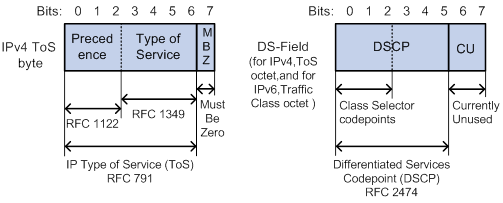
As shown in Figure 26, the ToS field in the IP header contains 8 bits. The first 3 bits (0 to 2) represent IP precedence from 0 to 7. According to RFC 2474, the ToS field is redefined as the differentiated services (DS) field. A DSCP value is represented by the first 6 bits (0 to 5) of the DS field and is in the range 0 to 63. The remaining 2 bits (6 and 7) are reserved.
Table 7 IP precedence
|
IP precedence (decimal) |
IP precedence (binary) |
Description |
|
0 |
000 |
Routine |
|
1 |
001 |
priority |
|
2 |
010 |
immediate |
|
3 |
011 |
flash |
|
4 |
100 |
flash-override |
|
5 |
101 |
critical |
|
6 |
110 |
internet |
|
7 |
111 |
network |
Table 8 DSCP values
|
DSCP value (decimal) |
DSCP value (binary) |
Description |
|
46 |
101110 |
ef |
|
10 |
001010 |
af11 |
|
12 |
001100 |
af12 |
|
14 |
001110 |
af13 |
|
18 |
010010 |
af21 |
|
20 |
010100 |
af22 |
|
22 |
010110 |
af23 |
|
26 |
011010 |
af31 |
|
28 |
011100 |
af32 |
|
30 |
011110 |
af33 |
|
34 |
100010 |
af41 |
|
36 |
100100 |
af42 |
|
38 |
100110 |
af43 |
|
8 |
001000 |
cs1 |
|
16 |
010000 |
cs2 |
|
24 |
011000 |
cs3 |
|
32 |
100000 |
cs4 |
|
40 |
101000 |
cs5 |
|
48 |
110000 |
cs6 |
|
56 |
111000 |
cs7 |
|
0 |
000000 |
be (default) |
802.1p priority
802.1p priority lies in the Layer 2 header. It applies to occasions where Layer 3 header analysis is not needed and QoS must be assured at Layer 2.
Figure 27 An Ethernet frame with an 802.1Q tag header
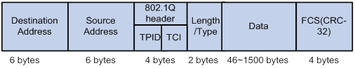
As shown in Figure 27, the 4-byte 802.1Q tag header contains the 2-byte tag protocol identifier (TPID) and the 2-byte tag control information (TCI). The value of the TPID is 0x8100. Figure 28 shows the format of the 802.1Q tag header. The Priority field in the 802.1Q tag header is called 802.1p priority, because its use is defined in IEEE 802.1p. Table 9 shows the values for 802.1p priority.
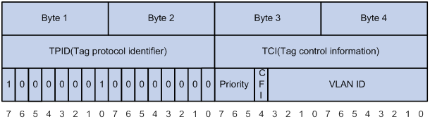
Table 9 Description on 802.1p priority
|
802.1p priority (decimal) |
802.1p priority (binary) |
Description |
|
0 |
000 |
best-effort |
|
1 |
001 |
background |
|
2 |
010 |
spare |
|
3 |
011 |
excellent-effort |
|
4 |
100 |
controlled-load |
|
5 |
101 |
video |
|
6 |
110 |
voice |
|
7 |
111 |
network-management |
Configuring time ranges
You can implement a service based on the time of the day by applying a time range to it. A time-based service takes effect only in time periods specified by the time range. For example, you can implement time-based ACL rules by applying a time range to them. If a time range does not exist, the service based on the time range does not take effect.
The following basic types of time ranges are available:
· Periodic time range—Recurs periodically on a day or days of the week.
· Absolute time range—Represents only a period of time and does not recur.
A time range is uniquely identified by the time range name. You can create a maximum of 1024 time ranges, each with a maximum of 32 periodic statements and 12 absolute statements. The active period of a time range is calculated as follows:
1. Combining all periodic statements.
2. Combining all absolute statements.
3. Taking the intersection of the two statement sets as the active period of the time range.
Configuration procedure
|
Step |
Command |
Remarks |
|
1. Enter system view. |
system-view |
N/A |
|
2. Create or edit a time range. |
time-range time-range-name { start-time to end-time days [ from time1 date1 ] [ to time2 date2 ] | from time1 date1 [ to time2 date2 ] | to time2 date2 } |
By default, no time ranges exist. |
Displaying and maintaining time ranges
Execute the display command in any view.
|
Task |
Command |
|
Display time range configuration and status. |
display time-range { time-range-name | all } |
Time range configuration example
Network requirements
As shown in Figure 29, configure an ACL on Device A to allow Host A to access the server only during 8:00 and 18:00 on working days from June 2015 to the end of the year.
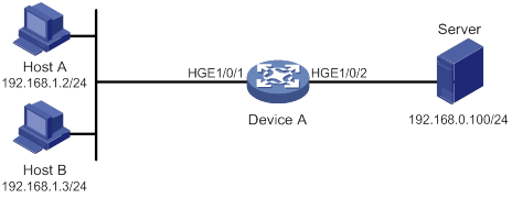
Configuration procedure
# Create a periodic time range during 8:00 and 18:00 on working days from June 2015 to the end of the year.
<DeviceA> system-view
[DeviceA] time-range work 8:0 to 18:0 working-day from 0:0 6/1/2015 to 24:00 12/31/2015
# Create an IPv4 basic ACL numbered 2001, and configure a rule in the ACL to permit packets only from 192.168.1.2/32 during the time range work.
[DeviceA] acl basic 2001
[DeviceA-acl-ipv4-basic-2001] rule permit source 192.168.1.2 0 time-range work
[DeviceA-acl-ipv4-basic-2001] rule deny source any time-range work
[DeviceA-acl-ipv4-basic-2001] quit
# Apply IPv4 basic ACL 2001 to filter outgoing packets on HundredGigE 1/0/2.
[DeviceA] interface hundredgige 1/0/2
[DeviceA-HundredGigE1/0/2] packet-filter 2001 outbound
[DeviceA-HundredGigE1/0/2] quit
Verifying the configuration
# Verify that the time range work is active on Device A.
[DeviceA] display time-range all
Current time is 13:58:35 6/29/2015 Friday
Time-range : work ( Active )
08:00 to 18:00 working-day
from 00:00 6/1/2015 to 00:00 1/1/2016
Configuring data buffers
Data buffers temporarily store packets to avoid packet loss.
An interface module has an ingress buffer and an egress buffer. Figure 30 shows the structure of ingress and egress buffers. An interface stores outgoing packets in the egress buffer when congestion occurs, and stores incoming packets in the ingress buffer when the CPU is busy.
Figure 30 Data buffer structure
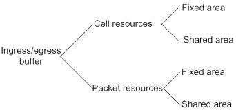
A buffer uses the following types of resources:
· Cell resources—Store packets. The buffer uses cell resources based on packet sizes. Suppose a cell resource provides 208 bytes. The buffer allocates one cell resource to a 128-byte packet and two cell resources to a 300-byte packet.
· Packet resources—Store packet pointers. A packet pointer indicates where the packet is located in cell resources. The buffer uses one packet resource for each incoming or outgoing packet.
Each type of resources has a fixed area and a shared area.
· Fixed area—Partitioned into queues, each of which is equally divided by all the interfaces on an interface module, as shown in Figure 31. When congestion occurs, the following rules apply:
a. An interface first uses the relevant queues of the fixed area to store packets.
b. When a queue is full, the interface uses the corresponding queue of the shared area.
c. When the queue in the shared area is also full, the interface discards subsequent packets.
The system allocates the fixed area among queues as specified by the user. Even if a queue is not full, other queues cannot preempt its space. Similarly, the share of a queue for an interface cannot be preempted by other interfaces even if it is not full.
· Shared area—Partitioned into queues, each of which is not equally divided by the interfaces, as shown in Figure 31. The system determines the actual shared-area space for each queue according to user configuration and the number of packets actually received and sent. If a queue is not full, other queues can preempt its space.
The system puts packets received on all interfaces into a queue in the order they arrive. When the queue is full, subsequent packets are dropped.
Figure 31 Fixed area and shared area
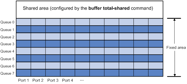
Configuration task list
|
Tasks at a glance |
|
(Required.) Enabling the Burst feature |
|
(Optional.) Configuring data buffer monitoring |
Enabling the Burst feature
The Burst feature enables the device to automatically allocate cell and packet resources. It is well suited to the following scenarios:
· Traffic enters a device from a high-speed interface and goes out of a low-speed interface.
· Traffic enters a device from multiple same-rate interfaces at the same time and goes out of an interface with the same rate.
To enable the Burst feature:
|
Step |
Command |
Remarks |
|
1. Enter system view. |
system-view |
N/A |
|
2. Enable the Burst feature. |
burst-mode enable |
By default, the Burst feature is disabled. The Burst feature takes effect only on known unicast packets. |
Configuring data buffer monitoring
The data buffer on a switch is shared by all interfaces for buffering packets during periods of congestion.
This feature allows you to identify the interfaces that use an excessive amount of data buffer space. Then, you can diagnose those interfaces for anomalies.
You can set a per-interface buffer usage threshold. The buffer usage threshold for a queue is the same as the per-interface threshold value. The switch automatically records buffer usage for each interface. When a queue on an interface uses more buffer space than the set threshold, the system counts one threshold violation for the queue.
To configure data buffer monitoring:
|
Step |
Command |
Remarks |
|
1. Enter system view. |
system-view |
N/A |
|
2. Set the packet counting mode to queue. |
statistic mode queue |
The default setting is vsi. |
|
3. Set a per-interface buffer usage threshold. |
In standalone mode: In IRF mode: |
The default setting is 100%. |
|
4. Return to user view. |
quit |
N/A |
|
5. (Optional.) Display the per-interface buffer usage threshold. |
display buffer usage interface [ interface-type [ interface-number ] ] |
Available in any view. |
Displaying and maintaining data buffers
Execute display commands in any view.
|
Task |
Command |
|
Display buffer usage statistics for interfaces. |
display buffer usage interface [ interface-type [ interface-number ] ] |
Burst configuration example
Network requirements
As shown in Figure 32, a server connects to the switch through a 1000 Mbps Ethernet interface. The server sends high-volume broadcast or multicast traffic to the hosts irregularly. Each host connects to the switch through a 100 Mbps network adapter.
Configure the switch to process high-volume traffic from the server to guarantee that packets can reach the hosts.
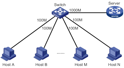
Configuration procedure
# Enter system view.
<Switch> system-view
# Enable the Burst feature.
[Switch] burst-mode enable
Numerics
802
QoS packet 802.1p priority, 84
A
absolute time range (ACL), 86, 86
access control
list. Use ACL
advanced configuration, 6
basics configuration, 4
configuration, 1, 3, 15
configuration restrictions, 3
copying, 12
display, 15
IPv4 advanced configuration, 6
IPv4 basic configuration, 4
IPv6 advanced configuration, 8
IPv6 basic configuration, 5
Layer 2 configuration, 10
maintain, 15
match order, 1
naming, 1
numbering, 1
packet filtering application (global), 13
packet filtering application (interface), 13
packet filtering application (VLAN interface list), 13
packet filtering configuration, 12
packet filtering default action, 14
packet filtering logging+SNMP notifications, 14
packet fragment filtering, 3
rule numbering, 2
time range configuration, 86, 86
time range display, 86
types, 1
user-defined configuration, 11
action
ACL packet filtering default action, 14
advanced ACL
type, 1
aggregate CAR
MQC approach, 75
QoS global CAR, 74
Appendix A
QoS acronyms, 81
Appendix B
QoS default priority maps, 81
Appendix C
QoS packet precedence, 83
applying
ACL packet filtering (global), 13
ACL packet filtering (interface), 13
ACL packet filtering (VLAN interface list), 13
QoS CA queue-based WRED table, 56, 57
QoS policy, 23
QoS policy (control plane), 24
QoS policy (global), 24
QoS policy (interface), 23
QoS policy (VLAN), 23
area
data buffer fixed, 88
data buffer shared, 88
auto
ACL auto match order sort, 1
ACL automatic rule numbering, 3
B
bandwidth
QoS overview, 18
QoS policy configuration, 21
basic ACL
type, 1
behavior
QoS traffic behavior definition, 22
best-effort QoS service model, 18
buffering
data. See data buffer
burst (data buffer), 89
burst feature (data buffer), 90
C
aggregate CAR, 74
aggregate CAR (MQC approach), 75
global CAR configuration, 74
global CAR display, 76
global CAR maintain, 76
hierarchical CAR, 74
cell
data buffer burst feature, 90
data buffer configuration, 88, 89
changing
QoS priority mapping interface port priority, 32
classifying
QoS class-based accounting, 77, 78
QoS traffic class definition, 22
committed access rate. Use CAR
configuring
ACL, 1, 3, 15
ACL (advanced), 6
ACL (basic), 4
ACL (Layer 2), 10
ACL (user-defined), 11
ACL packet filtering, 12
ACL packet filtering logging+SNMP notifications, 14
data buffer, 88, 89
data buffer monitoring, 89
IPv4 ACL (advanced), 6
IPv4 ACL (basic), 4
IPv6 ACL (advanced), 8
IPv6 ACL (basic), 5
QoS aggregate CAR (MQC approach), 75
QoS CA, 55
QoS CA queue-based WRED table, 56, 57
QoS class-based accounting, 77, 78
QoS CM, 48
QoS CM (per-queue), 49
QoS CM queue scheduling profile, 52, 53
QoS CM queue scheduling profile (interface), 53
QoS CM SP queuing, 49
QoS CM WFQ queuing, 50
QoS CM WRR queuing, 49
QoS congestion management (CM), 46
QoS congestion management SP+WFQ queuing, 51
QoS congestion management SP+WRR queuing, 50
QoS global CAR, 74
QoS GTS, 37
QoS MQC traffic policing, 41
QoS nesting, 67, 68
QoS non-MQC GTS, 42
QoS policy, 21
QoS priority mapping, 27, 30, 32
QoS priority mapping map, 31
QoS priority mapping port priority, 32
QoS priority mapping table+priority marking, 33
QoS priority mapping trusted interface packet priority, 31
QoS priority marking, 63, 64
QoS protocol packet rate limiting, 61, 62
QoS queue-based accounting, 80
QoS rate limit, 37, 42
QoS traffic filtering, 59, 60
QoS traffic policing, 37, 43
QoS traffic redirection, 70, 71
time range, 86, 86
congestion avoidance (QoS CA)
configuration, 55
queue-based WRED table, 56, 57
RED, 55
tail drop, 55
WRED, 55
WRED-queuing relationship, 56
congestion management
SP+WFQ queuing configuration, 51
SP+WRR queuing configuration, 50
congestion management (CM)
configuration, 48
display, 54
per-queue configuration, 49
QoS configuration, 46
queue scheduling profile, 52, 53
queue scheduling profile (interface), 53
queue scheduling profile configuration restrictions, 53
SP queuing, 46, 49
WFQ queuing, 48, 50
WRR queuing, 47, 49
control plane
QoS policy application, 23
QoS policy application (control plane), 24
copying
ACL, 12
D
data
buffer. See data buffer
burst enable, 89
burst feature enable, 90
configuration, 88, 89
display, 90
monitoring configuration, 89
default
ACL packet filtering default action, 14
defining
QoS policy, 22
QoS traffic behavior, 22
QoS traffic class, 22
deploying
QoS network deployment, 19
detecting
QoS CA RED, 55
QoS CA WRED, 55
device
ACL packet filtering application (global), 13
ACL packet filtering application (interface), 13
ACL packet filtering application (VLAN interface list), 13
ACL packet filtering configuration, 12
ACL packet filtering default action, 14
ACL packet filtering logging+SNMP notifications, 14
QoS CM (per-queue), 49
QoS CM configuration, 48
QoS policy application (control plane), 24
QoS policy application (global), 24
QoS policy application (interface), 23
QoS policy application (VLAN), 23
DiffServ QoS service model, 18
displaying
ACL, 15
data buffer, 90
QoS CA WRED, 58
QoS CM, 54
QoS global CAR, 76
QoS GTS, 43
QoS policies, 25
QoS priority mapping, 32
QoS queue-based accounting, 80
QoS rate limit, 43
QoS traffic policing, 43
time range, 86
drop priority (QoS priority mapping), 27
DSCP
QoS packet IP precedence and DSCP values, 83
E
enabling
data buffer burst, 89
data buffer burst feature, 90
evaluating
QoS traffic, 37
QoS traffic with token bucket, 37, 37, 37
F
filtering
ACL default action, 14
ACL packet filtering logging+SNMP notifications, 14
ACL packet fragments, 3
QoS traffic filtering configuration, 59, 60
fixed area
data buffer configuration, 88
forwarding
ACL configuration, 1, 3, 15
ACL configuration (advanced), 6
ACL configuration (basic), 4
ACL configuration (Layer 2), 10
ACL configuration (user-defined), 11
QoS token bucket, 37
fragment
ACL fragment filtering, 3
G
Generic Traffic Shaping. Use GTS
global
ACL packet filtering global application, 13
QoS policy application (global), 24
global CAR
aggregate CAR, 74
aggregate CAR (MQC approach), 75
configuration, 74
hierarchical CAR, 74
QoS display, 43
QoS GTS configuration, 37
QoS traffic shaping, 39
H
hierarchical CAR
global CAR, 74
I
IntServ QoS service model, 18
IP addressing
ACL configuration, 1, 3, 15
ACL configuration (advanced), 6
ACL configuration (Layer 2), 10
ACL configuration (user-defined), 11
QoS class-based accounting configuration, 77, 78
QoS traffic filtering configuration, 59, 60
IPv4
ACL configuration (IPv4 advanced), 6
ACL configuration (IPv4 basic), 4
ACL packet filtering configuration, 12
IPv6
ACL configuration (IPv6 advanced), 8
ACL configuration (IPv6 basic), 5
ACL packet filtering configuration, 12
L
Layer 2
ACL configuration, 10
ACL type, 1
limiting
QoS protocol packet rate limiting, 61, 62
QoS rate limit, 42
QoS rate limit display, 43
QoS rate limiting, 40
local
QoS priority mapping local precedence, 27
logging
ACL packet filtering logging, 14
M
maintaining
ACL, 15
QoS global CAR, 76
QoS policies, 25
QoS queue-based accounting, 80
matching
ACL match order auto, 1
ACL match order config, 1
mode
QoS priority mapping port priority, 32
modular QoS. Use MQC
QoS aggregate CAR, 75
QoS traffic policing, 41
N
naming
ACL, 1
ACL copy, 12
nesting
QoS configuration, 67, 68
network
ACL configuration (advanced), 6
ACL configuration (basic), 4
ACL configuration (Layer 2), 10
ACL configuration (user-defined), 11
ACL copy, 12
ACL packet filtering application (global), 13
ACL packet filtering application (interface), 13
ACL packet filtering application (VLAN interface list), 13
ACL packet filtering configuration, 12
ACL packet filtering default action, 14
ACL packet filtering logging+SNMP notifications, 14
ACL packet fragment filtering, 3
data buffer burst enable, 89
data buffer burst feature, 90
QoS aggregate CAR, 74
QoS aggregate CAR (MQC approach), 75
QoS CA configuration, 55
QoS CA WRED queue-based table, 56, 57
QoS CA WRED-queuing relationship, 56
QoS class-based accounting configuration, 77, 78
QoS CM (per-queue), 49
QoS CM configuration, 46, 48
QoS CM queue scheduling profile, 52, 53
QoS CM SP queuing, 49
QoS CM WFQ queuing, 50
QoS CM WRR queuing, 49
QoS congestion management SP+WFQ queuing configuration, 51
QoS congestion management SP+WRR queuing configuration, 50
QoS deployment, 19
QoS global CAR configuration, 74
QoS GTS, 39
QoS GTS configuration, 37
QoS hierarchical CAR, 74
QoS MQC, 21
QoS MQC traffic policing, 41
QoS nesting configuration, 67, 68
QoS non-MQC, 21
QoS non-MQC GTS, 42
QoS policy application, 23
QoS policy configuration, 21
QoS policy definition, 22
QoS priority mapping configuration, 27, 30
QoS priority mapping drop priority, 27
QoS priority mapping interface port priority, 32
QoS priority mapping map, 31
QoS priority mapping port priority, 32
QoS priority mapping table+priority marking configuration, 33
QoS priority mapping trusted interface packet priority, 31
QoS priority marking configuration, 63, 64
QoS protocol packet rate limiting, 61, 62
QoS queue-based accounting configuration, 80
QoS rate limit, 40, 42
QoS rate limit configuration, 37
QoS traffic behavior definition, 22
QoS traffic class definition, 22
QoS traffic evaluation, 37
QoS traffic filtering configuration, 59, 60
QoS traffic policing, 38
QoS traffic policing configuration, 37, 43
QoS traffic redirection configuration, 70, 71
network management
ACL configuration, 1, 3, 15
data buffer configuration, 88, 89
QoS overview, 18
QoS priority mapping configuration, 32
QoS service models, 18
QoS techniques, 18
time range configuration, 86, 86
non-modular QoS. Use non-MQC
QoS GTS, 42
notifying
ACL packet filtering logging+SNMP notifications, 14
numbering
ACL, 1
ACL automatic rule numbering, 3
ACL copy, 12
ACL rule, 2
ACL rule numbering step, 2
P
packet
data buffer burst enable, 89
data buffer burst feature, 90
data buffer configuration, 88, 89
QoS aggregate CAR, 74
QoS aggregate CAR (MQC approach), 75
QoS CA configuration, 55
QoS class-based accounting configuration, 77, 78
QoS global CAR configuration, 74
QoS GTS, 39
QoS hierarchical CAR, 74
QoS nesting configuration, 67, 68
QoS overview, 18
QoS policy configuration, 21
QoS priority mapping configuration, 27, 30, 32
QoS priority mapping port priority, 32
QoS priority mapping table+priority marking configuration, 33
QoS priority marking configuration, 63, 64
QoS protocol packet rate limiting, 61, 62
QoS queue-based accounting configuration, 80
QoS rate limit, 40
QoS traffic evaluation, 37
QoS traffic filtering configuration, 59, 60
QoS traffic policing, 38
QoS traffic redirection configuration, 70, 71
QoS trusted interface packet priority, 31
packet filtering
ACL configuration, 1, 3, 12, 15
ACL configuration (advanced), 6
ACL configuration (Layer 2), 10
ACL configuration (user-defined), 11
ACL default action, 14
ACL filtering application (global), 13
ACL filtering application (interface), 13
ACL filtering application (VLAN interface list), 13
ACL logging+SNMP notifications, 14
ACL packet fragment filtering, 3
parameter
QoS MQC, 21
QoS non-MQC, 21
periodic time range (ACL), 86, 86
per-queue QoS CM, 49
policy
QoS application, 23
QoS application (control plane), 24
QoS application (global), 24
QoS application (interface), 23
QoS application (VLAN), 23
QoS definition, 22
QoS MQC, 21
QoS non-MQC, 21
QoS policy configuration, 21
port
QoS priority mapping interface port priority, 32
QoS queue-based accounting configuration, 80
QoS trusted interface packet priority, 31
precedence
QoS priority mapping configuration, 27, 30, 32
QoS priority mapping local precedence, 27
QoS priority mapping port priority, 32
QoS priority mapping table+priority marking configuration, 33
priority
mapping. See priority mapping
marking. See priority marking
QoS packet 802.1p priority, 84
QoS packet IP precedence and DSCP values, 83
configuration, 27, 30, 32
drop priority, 27
interface port priority, 32
local precedence, 27
map, 27
map configuration, 31
mapping table+priority marking configuration, 33
port priority, 32
process, 28
trusted interface packet priority, 31
user priority, 27
configuration, 63, 64
procedure
applying ACL packet filtering (global), 13
applying ACL packet filtering (interface), 13
applying ACL packet filtering (VLAN interface list), 13
applying QoS CA queue-based WRED table, 56, 57
applying QoS policy, 23
applying QoS policy (control plane), 24
applying QoS policy (global), 24
applying QoS policy (interface), 23
applying QoS policy (VLAN), 23
changing QoS priority mapping interface port priority, 32
configuring ACL, 3
configuring ACL (advanced), 6
configuring ACL (basic), 4
configuring ACL (IPv4 advanced), 6
configuring ACL (IPv4 basic), 4
configuring ACL (IPv6 advanced), 8
configuring ACL (IPv6 basic), 5
configuring ACL (Layer 2), 10
configuring ACL (user-defined), 11
configuring ACL packet filtering, 12
configuring ACL packet filtering logging+SNMP notifications, 14
configuring data buffer, 89
configuring data buffer monitoring, 89
configuring QoS aggregate CAR (MQC approach), 75
configuring QoS CA queue-based WRED table, 56, 57
configuring QoS class-based accounting, 78
configuring QoS CM, 48
configuring QoS CM (per-queue), 49
configuring QoS CM queue scheduling profile, 52, 53
configuring QoS CM queue scheduling profile (interface), 53
configuring QoS CM SP queuing, 49
configuring QoS CM WFQ queuing, 50
configuring QoS CM WRR queuing, 49
configuring QoS congestion management SP+WFQ queuing, 51
configuring QoS congestion management SP+WRR queuing, 50
configuring QoS MQC traffic policing, 41
configuring QoS nesting, 68
configuring QoS non-MQC GTS, 42
configuring QoS priority mapping, 30
configuring QoS priority mapping map, 31
configuring QoS priority mapping port priority, 32
configuring QoS priority mapping table+priority marking, 33
configuring QoS priority mapping trusted interface packet priority, 31
configuring QoS priority marking, 64
configuring QoS protocol packet rate limiting, 62
configuring QoS rate limit, 42
configuring QoS traffic filtering, 60
configuring QoS traffic redirection, 70, 71
configuring time range, 86, 86
copying ACL, 12
defining QoS policy, 22
defining QoS traffic behavior, 22
defining QoS traffic class, 22
displaying ACL, 15
displaying data buffer, 90
displaying QoS CA WRED, 58
displaying QoS CM, 54
displaying QoS global CAR, 76
displaying QoS GTS, 43
displaying QoS policies, 25
displaying QoS priority mapping, 32
displaying QoS queue-based accounting, 80
displaying QoS rate limit, 43
displaying QoS traffic policing, 43
displaying time range, 86
enabling data buffer burst, 89
enabling data buffer burst feature, 90
maintaining ACL, 15
maintaining QoS global CAR, 76
maintaining QoS policies, 25
maintaining QoS queue-based accounting, 80
setting ACL packet filtering default action, 14
profile
QoS CM queue scheduling profile, 52, 53
QoS CM queue scheduling profile (interface), 53
protocols and standards
QoS protocol packet rate limiting, 61, 62
Q
ACL configuration, 1, 3, 15
aggregate CAR, 74
aggregate CAR (MQC approach), 75
Appendix A, Acronyms, 81
Appendix B, Default priority maps, 81
Appendix C, Packet precedence, 83
best-effort service model, 18
CA WRED display, 58
class-based accounting configuration, 77, 78
complicated traffic evaluation with token bucket, 37
congestion avoidance, 19
congestion avoidance (CA) configuration, 55
congestion avoidance (CA) RED, 55
congestion avoidance (CA) tail drop, 55
congestion avoidance (CA) WRED, 55
congestion avoidance (CA) WRED queue-based table, 56, 57
congestion avoidance (CA) WRED-queuing relationship, 56
congestion management, 19
congestion management (CM) (per-queue), 49
congestion management (CM) configuration, 46, 48
congestion management (CM) display, 54
congestion management (CM) queue scheduling profile, 52, 53
congestion management (CM) queue scheduling profile (interface), 53
congestion management (CM) queue scheduling profile configuration restrictions, 53
congestion management (CM) SP queuing, 46, 49
congestion management (CM) WFQ queuing, 48, 50
congestion management (CM) WRR queuing, 47, 49
congestion management SP+WFQ queuing configuration, 51
congestion management SP+WRR queuing configuration, 50
data buffer burst enable, 89
data buffer burst feature, 90
data buffer configuration, 88, 89
data buffer display, 90
data buffer monitoring configuration, 89
device process flow, 19
DiffServ service model, 18
global CAR configuration, 74
global CAR display, 76
global CAR maintain, 76
GTS, 39
GTS configuration, 37
GTS display, 43
hierarchical CAR, 74
IntServ service model, 18
MQC configuration, 21
MQC traffic policing, 41
nesting configuration, 67, 68
network deployment, 19
non-MQC, 21
non-MQC GTS, 42
overview, 18
policy application, 23
policy application (control plane), 24
policy application (global), 24
policy application (interface), 23
policy application (VLAN), 23
policy application restrictions (control plane), 25
policy application restrictions (VLAN), 24
policy configuration, 21
policy definition, 22
policy display, 25
policy maintain, 25
priority mapping configuration, 27, 30, 32
priority mapping display, 32
priority mapping drop priority, 27
priority mapping interface port priority, 32
priority mapping local precedence, 27
priority mapping map, 27, 31
priority mapping port priority, 32
priority mapping process, 28
priority mapping table+priority marking configuration, 33
priority mapping trusted interface packet priority, 31
priority mapping user priority, 27
priority marking configuration, 63, 64
protocol packet rate limiting, 61, 62
queue-based accounting configuration, 80
queue-based accounting display, 80
queue-based accounting maintain, 80
rate limit, 40
rate limit configuration, 37, 42
rate limit display, 43
service models, 18
techniques, 18
token bucket, 37
traffic behavior definition, 22
traffic class definition, 22
traffic classification, 19
traffic evaluation, 37
traffic evaluation with token bucket, 37, 37
traffic filtering configuration, 59, 60
traffic policing, 19, 38
traffic policing configuration, 37, 43
traffic policing display, 43
traffic redirection configuration, 70, 71
traffic shaping, 19
Quality of Service. Use QoS
queuing
data buffer burst feature, 90
data buffer configuration, 88, 89
QoS CA RED, 55
QoS CA WRED, 55
QoS CA WRED-queuing relationship, 56
QoS CM queue scheduling profile (interface), 53
QoS CM scheduling profile, 52, 53
QoS CM SP queuing, 46, 49
QoS CM WFQ queuing, 48, 50
QoS CM WRR queuing, 47, 49
QoS congestion management SP+WFQ queuing configuration, 51
QoS congestion management SP+WRR queuing configuration, 50
QoS queue-based accounting configuration, 80
R
random early detection. Use RED
rate limiting
QoS protocol packet rate limiting, 61, 62
QoS rate limit, 42
QoS rate limit display, 43
QoS rate limiting, 40
QoS rate limiting configuration, 37
redirecting
QoS traffic redirection, 70, 71
restrictions
ACL configuration, 3
QoS CM queue scheduling profile configuration, 53
QoS policy application (control plane), 25
QoS policy application (VLAN), 24
routing
ACL configuration, 1, 3, 15
ACL configuration (advanced), 6
ACL configuration (basic), 4
ACL configuration (Layer 2), 10
ACL configuration (user-defined), 11
QoS CM (per-queue), 49
QoS CM configuration, 48
QoS GTS configuration, 37
QoS priority mapping configuration, 27, 30, 32
QoS priority mapping port priority, 32
QoS priority mapping table+priority marking configuration, 33
QoS rate limit configuration, 37
QoS traffic policing configuration, 37, 43
rule
ACL auto match order sort, 1
ACL automatic rule numbering, 3
ACL config match order sort, 1
ACL numbering, 2
ACL numbering step, 2
S
scheduling
QoS CM queue scheduling profile, 52, 53
security
ACL configuration, 1, 3, 15
ACL configuration (advanced), 6
ACL configuration (basic), 4
ACL configuration (IPv4 advanced), 6
ACL configuration (IPv4 basic), 4
ACL configuration (IPv6 advanced), 8
ACL configuration (IPv6 basic), 5
ACL configuration (Layer 2), 10
ACL configuration (user-defined), 11
service
QoS best-effort service model, 18
QoS CA configuration, 55
QoS CM configuration, 46
QoS DiffServ service model, 18
QoS global CAR configuration, 74
QoS IntServ service model, 18
QoS models, 18
QoS nesting configuration, 67, 68
QoS overview, 18
QoS policy configuration, 21
QoS priority marking configuration, 63, 64
QoS techniques, 18
QoS traffic filtering configuration, 59, 60
setting
ACL packet filtering default action, 14
shared area
data buffer configuration, 88
SNMP
ACL packet filtering SNMP notifications, 14
sorting
ACL auto match order sort, 1
ACL config match order sort, 1
SP queuing
QoS CM classification, 46
QoS CM configuration, 49
SP+WFQ queuing
configuration, 51
SP+WRR queuing
configuration, 50
statistics
QoS class-based accounting configuration, 77, 78
QoS queue-based accounting configuration, 80
switching
QoS CM configuration, 46
QoS CM queue scheduling profile (interface), 53
T
table
QoS CA WRED queue-based table, 56, 57
tail drop (QoS CA), 55
TCP
QoS CA RED, 55
QoS CA tail drop, 55
time range
configuration, 86, 86
display, 86
token bucket
QoS complicated traffic evaluation, 37
QoS traffic evaluation, 37, 37
QoS traffic forwarding, 37
traffic
ACL configuration, 1, 3, 15
ACL configuration (advanced), 6
ACL configuration (Layer 2), 10
ACL configuration (user-defined), 11
data buffer burst enable, 89
QoS aggregate CAR, 74
QoS aggregate CAR (MQC approach), 75
QoS CA configuration, 55
QoS CA WRED queue-based table, 56, 57
QoS CA WRED-queuing relationship, 56
QoS class-based accounting configuration, 77, 78
QoS CM, 46, See also under congestion management (CM)
QoS CM (per-queue), 49
QoS CM configuration, 46, 48
QoS CM queue scheduling profile, 52, 53
QoS CM SP queuing, 49
QoS CM WFQ queuing, 50
QoS CM WRR queuing, 49
QoS congestion avoidance, 19
QoS congestion management, 19
QoS congestion management SP+WFQ queuing configuration, 51
QoS congestion management SP+WRR queuing configuration, 50
QoS device process flow, 19
QoS global CAR configuration, 74
QoS GTS, 39
QoS GTS configuration, 37
QoS hierarchical CAR, 74
QoS MQC, 21
QoS MQC traffic policing, 41
QoS nesting configuration, 67, 68
QoS network deployment, 19
QoS non-MQC, 21
QoS non-MQC GTS, 42
QoS overview, 18
QoS policy application, 23
QoS policy application (control plane), 24
QoS policy application (global), 24
QoS policy application (interface), 23
QoS policy application (VLAN), 23
QoS policy configuration, 21
QoS policy definition, 22
QoS priority map, 27
QoS priority mapping configuration, 32
QoS priority mapping interface port priority, 32
QoS priority mapping map, 31
QoS priority mapping port priority, 32
QoS priority mapping process, 28
QoS priority mapping table+priority marking configuration, 33
QoS priority mapping trusted interface packet priority, 31
QoS priority marking configuration, 63, 64
QoS queue-based accounting configuration, 80
QoS rate limit, 40, 42
QoS rate limit configuration, 37
QoS token bucket, 37
QoS traffic behavior definition, 22
QoS traffic class definition, 22
QoS traffic classification, 19
QoS traffic evaluation, 37
QoS traffic filtering configuration, 59, 60
QoS traffic policing, 19, 38
QoS traffic policing configuration, 37, 43
QoS traffic redirection configuration, 70, 71
QoS traffic shaping, 19
traffic policing
QoS display, 43
trapping
ACL packet filtering logging+SNMP notifications, 14
trusted
QoS trusted interface packet priority, 31
type
ACL advanced, 1
ACL auto match order sort, 1
ACL basic, 1
ACL config match order sort, 1
ACL Layer 2, 1
ACL user-defined, 1
U
user
QoS priority mapping user priority, 27
user-defined ACL
type, 1
V
VLAN
QoS nesting configuration, 67, 68
QoS policy application, 23
QoS policy application (VLAN), 23
W
weighted
random early detection. Use WRED
WFQ queuing
QoS CM bandwidth, 48
QoS CM configuration, 50
QoS CA queue-based WRED table, 56, 57
QoS CA WRED display, 58
QoS CA WRED-queuing relationship, 56
WRR queuing
QoS CM basic queuing, 47
QoS CM configuration, 49
QoS CM group-based queuing, 47