- Table of Contents
- Related Documents
-
01-Text
Download Book (2.58 MB)Contents
Configuring Ethernet interfaces
Ethernet interface naming conventions
Configuring a management Ethernet interface
Configuring common Ethernet interface settings
Splitting a 40-GE interface and combining 10-GE breakout interfaces
Configuring basic settings of an Ethernet interface or subinterface
Configuring the link mode of an Ethernet interface
Configuring jumbo frame support
Configuring physical state change suppression on an Ethernet interface
Configuring dampening on an Ethernet interface
Enabling loopback testing on an Ethernet interface
Configuring generic flow control on an Ethernet interface
Configuring PFC on an Ethernet interface
Setting the statistics polling interval
Configuring a Layer 2 Ethernet interface
Configuring storm control on an Ethernet interface
Forcibly bringing up a fiber port
Configuring a Layer 3 Ethernet interface or subinterface
Setting the MTU for an Ethernet interface or subinterface
Displaying and maintaining an Ethernet interface or subinterface
Configuring loopback, null, and inloopback interfaces
Configuring a loopback interface
Configuring an inloopback interface
Displaying and maintaining loopback, null, and inloopback interfaces
Configuration restrictions and guidelines
Displaying and maintaining bulk interface configuration
Configuring the MAC address table
How a MAC address entry is created
MAC address table configuration task list
Configuring MAC address entries
Adding or modifying a static or dynamic MAC address entry globally
Adding or modifying a static or dynamic MAC address entry on an interface
Adding or modifying a blackhole MAC address entry
Adding or modifying a multiport unicast MAC address entry
Disabling MAC address learning
Disabling global MAC address learning
Disabling MAC address learning on interfaces
Setting the aging timer for dynamic MAC address entries
Enabling MAC address synchronization
Configuring MAC address move notifications and suppression
Enabling ARP fast update for MAC address moves
Enabling MAC address learning at ingress
Configuring the base MAC address
Enabling SNMP notifications for the MAC address table
Displaying and maintaining the MAC address table
MAC address table configuration example
Configuring the MAC Information mode
Setting the MAC change notification interval
Setting the MAC Information queue length
MAC Information configuration example
Configuration restrictions and guidelines
Configuring Ethernet link aggregation
Aggregation group, member port, and aggregate interface
Aggregation states of member ports in an aggregation group
Aggregating links in static mode
Setting the aggregation state of each member port
Aggregating links in dynamic mode
How dynamic link aggregation works
Load sharing modes for link aggregation groups
Ethernet link aggregation configuration task list
Configuring an aggregation group
Configuration restrictions and guidelines
Configuring a Layer 2 aggregation group
Configuring a Layer 3 aggregation group
Configuring an aggregate interface
Configuring the description of an aggregate interface
Setting the MAC address for an aggregate interface
Specifying ignored VLANs for a Layer 2 aggregate interface
Setting the MTU for a Layer 3 aggregate interface
Setting the minimum and maximum numbers of Selected ports for an aggregation group
Setting the expected bandwidth for an aggregate interface
Configuring an edge aggregate interface
Enabling BFD for an aggregation group
Shutting down an aggregate interface
Restoring the default settings for an aggregate interface
Configuring load sharing for link aggregation groups
Setting load sharing modes for link aggregation groups
Enabling local-first load sharing for link aggregation
Configuring link aggregation load sharing algorithm settings
Enabling link-aggregation traffic redirection
Configuration restrictions and guidelines
Configuring the link aggregation capability for the device
Displaying and maintaining Ethernet link aggregation
Ethernet link aggregation configuration examples
Layer 2 static aggregation configuration example
Layer 2 dynamic aggregation configuration example
Layer 2 aggregation load sharing configuration example
Layer 2 edge aggregate interface configuration example
Layer 3 static aggregation configuration example
Layer 3 dynamic aggregation configuration example
Layer 3 aggregation load sharing configuration example
Layer 3 edge aggregate interface configuration example
Assigning a port to an isolation group
Displaying and maintaining port isolation
Port isolation configuration example
Configuring spanning tree protocols
Calculation process of the STP algorithm
MSTP implementation on devices
Spanning tree configuration task lists
Setting the spanning tree mode
Configuring the root bridge or a secondary root bridge
Configuring the device as the root bridge of a specific spanning tree
Configuring the device as a secondary root bridge of a specific spanning tree
Configuring the device priority
Configuring the maximum hops of an MST region
Configuring the network diameter of a switched network
Configuration restrictions and guidelines
Configuring the BPDU transmission rate
Configuration restrictions and guidelines
Configuring path costs of ports
Specifying a standard for the device to use when it calculates the default path cost
Configuring path costs of ports
Configuring the port link type
Configuration restrictions and guidelines
Configuring the mode a port uses to recognize and send MSTP frames
Enabling outputting port state transition information
Enabling the spanning tree feature
Enabling the spanning tree feature in STP/RSTP/MSTP mode
Enabling the spanning tree feature in PVST mode
Configuration restrictions and guidelines
Performing mCheck in interface view
Disabling inconsistent PVID protection
Configuration restrictions and guidelines
Digest Snooping configuration example
Configuring No Agreement Check
No Agreement Check configuration example
Configuration restrictions and guidelines
Configuring protection features
Configuring port role restriction
Configuring TC-BPDU transmission restriction
Enabling the device to log events of detecting or receiving TC BPDUs
Enabling SNMP notifications for new-root election and topology change events
Displaying and maintaining the spanning tree
Spanning tree configuration example
Loop detection configuration task list
Enabling loop detection globally
Enabling loop detection on a port
Setting the loop protection action
Setting the global loop protection action
Setting the loop protection action on a Layer 2 Ethernet interface
Setting the loop protection action on a Layer 2 aggregate interface
Setting the loop detection interval
Displaying and maintaining loop detection
Loop detection configuration example
Configuring basic VLAN settings
Assigning an access port to a VLAN
Assigning a trunk port to a VLAN
Assigning a hybrid port to a VLAN
Displaying and maintaining VLANs
Port-based VLAN configuration example
VLAN mapping application scenarios
VLAN mapping configuration task list
Configuring one-to-one VLAN mapping
Configuring one-to-two VLAN mapping
Configuring zero-to-two VLAN mapping
Configuring two-to-two VLAN mapping
Configuring two-to-three VLAN mapping
Displaying and maintaining VLAN mapping
VLAN mapping configuration examples
One-to-one VLAN mapping configuration example
One-to-two and two-to-two VLAN mapping configuration example
Performing basic LLDP configurations
Setting the LLDP operating mode
Setting the LLDP reinitialization delay
Configuring the advertisable TLVs
Configuring the management address and its encoding format
Setting an encapsulation format for LLDP frames
Disabling LLDP PVID inconsistency check
Enabling LLDP and DCBX TLV advertising
Configuring LLDP trapping and LLDP-MED trapping
Setting the source MAC address of LLDP frames
Enabling the device to generate ARP or ND entries for received management address LLDP TLVs·
Displaying and maintaining LLDP
Basic LLDP configuration example
Configuring service loopback groups
Displaying and maintaining service loopback groups
Configuring Ethernet interfaces
The Switch Series supports Ethernet interfaces, management Ethernet interfaces, Console interfaces, and USB interfaces. For the interface types and the number of interfaces supported by a switch model, see the installation guide.
This chapter describes how to configure management Ethernet interfaces and Ethernet interfaces.
Ethernet interface naming conventions
For a switch in an IRF fabric, its Ethernet interfaces are numbered in the format of interface type A/B/C/D. For a switch not in an IRF fabric, its Ethernet interfaces are numbered in the format of interface type B/C/D. The following definitions apply:
· A—IRF member ID.
· B—Slot number of the card in the switch.
· C—Sub-slot number on a card.
· D—Number of an interface on a card.
Configuring a management Ethernet interface
A management interface uses an RJ-45 connector. You can connect the interface to a PC for software loading and system debugging, or connect it to a remote NMS for remote system management.
To configure a management Ethernet interface:
|
Step |
Command |
Remarks |
|
1. Enter system view. |
system-view |
N/A |
|
2. Enter management Ethernet interface view. |
interface M-GigabitEthernet interface-number |
N/A |
|
3. (Optional.) Set the interface description. |
description text |
The default setting is M-GigabitEthernet0/0/0 Interface. |
|
4. (Optional.) Shut down the interface. |
shutdown |
By default, the management Ethernet interface is up. |
|
|
NOTE: Set the same speed and duplex mode for a management Ethernet interface and its peer port. |
Configuring common Ethernet interface settings
This section describes the settings common to Layer 2 Ethernet interfaces, Layer 3 Ethernet interfaces, and Layer 3 Ethernet subinterfaces. For more information about the settings specific to Layer 2 Ethernet interfaces or subinterfaces, see "Configuring a Layer 2 Ethernet interface." For more information about the settings specific to Layer 3 Ethernet interfaces or subinterfaces, see "Configuring a Layer 3 Ethernet interface or subinterface."
Splitting a 40-GE interface and combining 10-GE breakout interfaces
Configuration restrictions and guidelines
All interfaces on the LSXM1CGQ6QGHB1, LSXM1CGQ18QGHB1, LSXM1CGQ18QGHF1, and LSXM1CGQ36HB1 interface modules can be split into four breakout interfaces.
100-GE interfaces on the LSXM1TGS48C2HB1 interface modules cannot be split into four breakout interfaces.
Interfaces numbered 1 through 4, 17 through 22, 35, and 36 on LSXM1QGS36HB1 interface modules can be split into four breakout interfaces.
Interfaces numbered 1 through 13, 16, 19, 22, 25, 28, 31, 34, 37, 40, 43, and 46 on LSXM1QGS48HB1 interface modules can be split into four breakout interfaces.
Splitting a 40-GE interface into four 10-GE breakout interfaces
As a best practice for the long-term system stabilization, reboot the device after configuration.
You can use a 40-GE interface as a single interface. To improve port density, reduce costs, and improve network flexibility, you can also split a 40-GE interface into four 10-GE breakout interfaces. For example, you can split 40-GE interface FortyGigE 1/0/1 into four 10-GE breakout interfaces Ten-GigabitEthernet 1/0/1:1 through Ten-GigabitEthernet 1/0/1:4.
A 40-GE interface split into four 10-GE breakout interfaces must use a dedicated 1-to-4 cable. For more information about the cable, see the installation guides.
The 10-GE breakout interfaces support the same configuration and attributes as common 10-GE interfaces, except that they are numbered in a different way.
After the using tengige command is successfully configured, you can view the four 10-GE breakout interfaces by using the display interface brief command.
To split a 40-GE interface into four 10-GE breakout interfaces:
|
Step |
Command |
Remarks |
|
1. Enter system view. |
system-view |
N/A |
|
2. Enter 40-GE interface view. |
interface interface-type interface-number |
N/A |
|
3. Split the 40-GE interface into four 10-GE breakout interfaces. |
using tengige |
By default, a 40-GE interface is not split and operates as a single interface. |
Combining four 10-GE breakout interfaces into a 40-GE interface
As a best practice for the long-term system stabilization, reboot the device after configuration.
If you need higher bandwidth on a single interface, you can combine the four 10-GE breakout interfaces into a 40-GE interface.
After you combine the four 10-GE breakout interfaces, replace the dedicated 1-to-4 cable with a dedicated 1-to-1 cable or a 40-GE transceiver module. For more information about the cable or transceiver module, see the installation guides.
After the using fortygige command is successfully configured, you can view the 40-GE interface by using the display interface brief command.
To combine four 10-GE breakout interfaces into a 40-GE interface:
|
Step |
Command |
Remarks |
|
1. Enter system view. |
system-view |
N/A |
|
2. Enter the view of any 10-GE breakout interface. |
interface interface-type interface-number |
N/A |
|
3. Combine the four 10-GE breakout interfaces into a 40-GE interface. |
using fortygige |
By default, a 10-GE breakout interface operates as a single interface. |
Configuring basic settings of an Ethernet interface or subinterface
You can configure an Ethernet interface to operate in one of the following duplex modes:
· Full-duplex mode—The interface can send and receive packets simultaneously.
· Autonegotiation mode—The interface negotiates a duplex mode with its peer.
You can set the speed of an Ethernet interface or enable it to automatically negotiate a speed with its peer.
Configuring an Ethernet interface
|
Step |
Command |
Remarks |
|
1. Enter system view. |
system-view |
N/A |
|
2. Enter Ethernet interface view. |
interface interface-type interface-number |
N/A |
|
3. Set the description for the Ethernet interface. |
description text |
The default setting is interface-name Interface. For example, HundredGigE1/0/1 Interface. |
|
4. Set the duplex mode for the Ethernet interface. |
duplex { auto | full } |
By default, the duplex mode is auto for Ethernet interfaces. |
|
5. Set the speed for the Ethernet interface. |
speed { 1000 | 10000 | 40000 | 100000 | auto } |
The default setting is auto for Ethernet interfaces. Support for the keywords depends on the interface type. For more information, use the speed ? command in interface view. |
|
6. Set the expected bandwidth for the Ethernet interface. |
bandwidth bandwidth-value |
By default, the expected bandwidth (in kbps) is the interface baud rate divided by 1000. |
|
7. Restore the default settings for the Ethernet interface. |
default |
N/A |
|
8. Bring up the Ethernet interface. |
undo shutdown |
By default, Ethernet interfaces are in down state. The loopback, shutdown, and port up-mode commands are mutually exclusive. |
Configuring an Ethernet subinterface
|
Step |
Command |
Remarks |
|
1. Enter system view. |
system-view |
N/A |
|
2. Create an Ethernet subinterface. |
interface interface-type interface-number.subnumber |
N/A |
|
3. Set the description for the Ethernet subinterface. |
description text |
The default setting is interface-name Interface. For example, HundredGigE1/0/1.1 Interface. |
|
4. Restore the default settings for the Ethernet subinterface. |
default |
N/A |
|
5. Set the expected bandwidth for the Ethernet subinterface. |
bandwidth bandwidth-value |
By default, the expected bandwidth (in kbps) is the interface baud rate divided by 1000. |
|
6. Bring up the Ethernet subinterface. |
undo shutdown |
By default, Ethernet subinterfaces are in down state. The shutdown and port up-mode commands are mutually exclusive. |
Configuring the link mode of an Ethernet interface
|
|
CAUTION: After you change the link mode of an Ethernet interface, all commands (except the shutdown command) on the Ethernet interface are restored to their defaults in the new link mode. |
The interfaces on this Switch Series can operate either as Layer 2 or Layer 3 Ethernet interfaces.
You can set the link mode to bridge or route.
You might fail to change the link mode of an Ethernet interface because of conflicting configurations on the interface. To solve this problem, manually delete all configurations of the interface and change the link mode again.
To configure the link mode of an Ethernet interface:
|
Step |
Command |
Remarks |
|
1. Enter system view. |
system-view |
N/A |
|
2. Enter Ethernet interface view. |
interface interface-type interface-number |
N/A |
|
3. Configure the link mode of the Ethernet interface. |
port link-mode { bridge | route } |
By default, Ethernet interfaces operate in bridge mode. |
Configuring jumbo frame support
An Ethernet interface might receive frames larger than the standard Ethernet frame size during high-throughput data exchanges, such as file transfers. These frames are called jumbo frames.
The Ethernet interface processes jumbo frames in the following ways:
· When the Ethernet interface is configured to deny jumbo frames, the Ethernet interface discards jumbo frames.
· When the Ethernet interface is configured with jumbo frame support, the Ethernet interface performs the following operations:
? Processes jumbo frames within the specified length.
? Discards jumbo frames that exceed the specified length.
To configure jumbo frame support in interface view:
|
Step |
Command |
Remarks |
|
1. Enter system view. |
system-view |
N/A |
|
2. Enter Ethernet interface view. |
interface interface-type interface-number |
N/A |
|
3. Configure jumbo frame support. |
jumboframe enable [ size ] |
By default, the switch allows jumbo frames within 12288 bytes to pass through all Ethernet interfaces. |
Configuring physical state change suppression on an Ethernet interface
|
|
IMPORTANT: Do not enable this feature on an interface that has RRPP, spanning tree protocols, or Smart Link enabled. |
The physical link state of an Ethernet interface is either up or down. Each time the physical link of an interface comes up or goes down, the interface immediately reports the change to the CPU. The CPU then performs the following operations:
· Notifies the upper-layer protocol modules (such as routing and forwarding modules) of the change for guiding packet forwarding.
· Automatically generates traps and logs to inform users to take the correct actions.
To prevent frequent physical link flapping from affecting system performance, configure physical state change suppression. You can configure this feature to suppress only link-down events, only link-up events, or both. If an event of the specified type still exists when the suppression interval expires, the system reports the event.
When you configure this feature, follow these guidelines:
· To suppress only link-down events, configure the link-delay [ msec ] delay-time command.
· To suppress only link-up events, configure the link-delay [ msec ] delay-time mode up command.
· To suppress both link-down and link-up events, configure the link-delay [ msec ] delay-time mode updown command.
To configure physical state change suppression on an Ethernet interface:
|
Step |
Command |
Remarks |
|
1. Enter system view. |
system-view |
N/A |
|
2. Enter Ethernet interface view. |
interface interface-type interface-number |
N/A |
|
3. Configure physical state change suppression. |
link-delay [ msec ] delay-time [ mode { up | updown }] |
By default, the link-down or link-up event is immediately reported to the CPU. If you configure this command multiple times on an Ethernet interface, the most recent configuration takes effect. |
Configuring dampening on an Ethernet interface
The interface dampening feature uses an exponential decay mechanism to prevent excessive interface flapping events from adversely affecting routing protocols and routing tables in the network. Suppressing interface state change events protects the system resources.
If an interface is not dampened, its state changes are reported. For each state change, the system also generates an SNMP trap and log message.
After a flapping interface is dampened, it does not report its state changes to the CPU. For state change events, the interface only generates SNMP trap and log messages.
Parameters
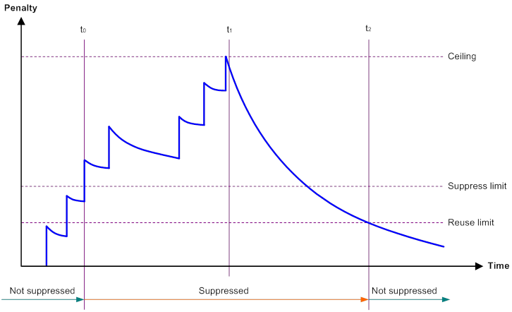
· Penalty—The interface has an initial penalty of 0. When the interface flaps, the penalty increases by 1000 for each down event until the ceiling is reached. It does not increase for up events. When the interface stops flapping, the penalty decreases by half each time the half-life timer expires until the penalty drops to the reuse threshold.
· Ceiling—The penalty stops increasing when it reaches the ceiling.
· Suppress-limit—The accumulated penalty that triggers the device to dampen the interface. In dampened state, the interface does not report its state changes to the CPU. For state change events, the interface only generates SNMP traps and log messages.
· Reuse-limit—When the accumulated penalty decreases to this reuse threshold, the interface is not dampened. Interface state changes are reported to the upper layers. For each state change, the system also generates an SNMP trap and log message.
· Decay—The amount of time (in seconds) after which a penalty is decreased.
· Max-suppress-time—The maximum amount of time the interface can be dampened. If the penalty is still higher than the reuse threshold when this timer expires, the penalty stops increasing for down events. The penalty starts to decrease until it drops below the reuse threshold.
The ceiling is equal to 2(Max-suppress-time/Decay) × reuse-limit. It is not user configurable.
Figure 1 shows the change rule of the penalty value. The lines t0 and t2 indicate the start time and end time of the suppression, respectively. The period from t0 to t2 indicates the suppression period, t0 to t1 indicates the max-suppress-time, and t1 to t2 indicates the complete decay period.
Figure 1 Change rule of the penalty value
Configuration restrictions and guidelines
When you configure dampening on an Ethernet interface, follow these restrictions and guidelines:
· The dampening command and the link-delay command cannot be configured together on an interface.
· The dampening command does not take effect on the administratively down events. When you execute the shutdown command, the penalty restores to 0, and the interface reports the down event to the upper-layer protocols.
· Do not enable the dampening feature on an interface with RRPP, MSTP, or Smart Link enabled.
Configuration procedure
To configure dampening on an Ethernet interface:
|
Step |
Command |
Remarks |
|
1. Enter system view. |
system-view |
N/A |
|
2. Enter Ethernet interface view. |
interface interface-type interface-number |
N/A |
|
3. Enable dampening on the interface. |
dampening [ half-life reuse suppress max-suppress-time ] |
By default, interface dampening is disabled on Ethernet interfaces. |
Enabling loopback testing on an Ethernet interface
|
|
CAUTION: After you enable this feature on an Ethernet interface, the interface cannot forward data traffic correctly. |
Perform this task to determine whether an Ethernet link works correctly.
Loopback testing includes the following types:
· Internal loopback testing—Tests the device where the Ethernet interface resides. The Ethernet interface sends outgoing packets back to the local device. If the device fails to receive the packets, the device fails.
· External loopback testing—Tests the inter-device link. The Ethernet interface sends incoming packets back to the remote device. If the remote device fails to receive the packets, the inter-device link fails.
Configuration restrictions and guidelines
· On an administratively shut down Ethernet interface (displayed as in ADM or Administratively DOWN state), you cannot perform an internal or external loopback test.
· The speed, duplex, and shutdown commands are not available during a loopback test.
· A loopback test cannot be performed on an interface configured with the port up-mode command.
· During a loopback test, the Ethernet interface operates in full duplex mode. When a loopback test is complete, the port returns to its duplex setting..
Configuration procedure
To enable loopback testing on an Ethernet interface:
|
Step |
Command |
Remarks |
|
1. Enter system view. |
system-view |
N/A |
|
2. Enter Ethernet interface view. |
interface interface-type interface-number |
N/A |
|
3. Enable loopback testing. |
loopback { external | internal } |
By default, no loopback test is performed. |
Configuring generic flow control on an Ethernet interface
To avoid dropping packets on a link, you can enable generic flow control at both ends of the link. When traffic congestion occurs at the receiving end, the receiving end sends a flow control (Pause) frame to ask the sending end to suspend sending packets. Generic flow control includes the following types:
· TxRx-mode generic flow control—Enabled by using the flow-control command. With TxRx-mode generic flow control enabled, an interface can both send and receive flow control frames:
? When congestion occurs, the interface sends a flow control frame to its peer.
? When the interface receives a flow control frame from its peer, it suspends sending packets to its peer.
· Rx-mode generic flow control—Enabled by using the flow-control receive enable command. With Rx-mode generic flow control enabled, an interface can receive flow control frames, but it cannot send flow control frames:
? When congestion occurs, the interface cannot send flow control frames to its peer.
? When the interface receives a flow control frame from its peer, it suspends sending packets to its peer.
To handle unidirectional traffic congestion on a link, configure the flow-control receive enable command at one end and the flow-control command at the other end. To enable both ends of a link to handle traffic congestion, configure the flow-control command at both ends.
This feature is mutually exclusive with PFC.
To enable generic flow control on an Ethernet interface:
|
Step |
Command |
Remarks |
|
1. Enter system view. |
system-view |
N/A |
|
2. Enter Ethernet interface view. |
interface interface-type interface-number |
N/A |
|
3. Enable generic flow control. |
·
Enable TxRx-mode generic flow control: ·
Enable Rx-mode generic flow control: |
By default, generic flow control is disabled on an Ethernet interface. |
Configuring PFC on an Ethernet interface
When congestion occurs in the network, the local device notifies the peer to stop sending packets carrying the specified 802.1p priority if all of the following conditions exist:
· Both the local end and the remote end have PFC enabled.
· Both the local end and the remote end have the priority-flow-control no-drop dot1p command configured.
· The specified 802.1p priority is in the 802.1p priority list specified by the dot1p-list argument.
· The local end receives a packet carrying the specified 802.1p priority.
The state of the PFC feature is determined by the PFC configuration on the local end and on the peer end. In Table 1:
· The first row lists the PFC configuration on the local interface.
· The first column lists the PFC configuration on the peer.
· The Enabled and Disabled fields in other cells are possible negotiation results.
Make sure all interfaces that a data flow passes through have the same PFC configuration.
Table 1 PFC configurations and negotiation results
|
Local (right) Peer (below) |
enable |
auto |
Default |
|
enable |
Enabled |
Enabled. |
Disabled |
|
auto |
Enabled |
· Enabled if negotiation succeeds. · Disabled if negotiation fails. |
Disabled |
|
Default |
Disabled |
Disabled. |
Disabled |
Configuration restrictions and guidelines
When you configure PFC, follow these restrictions and guidelines:
· For IRF and other protocols to operate correctly, as a best practice, do not enable PFC for 802.1p priorities 0, 6, and 7.
· To avoid packet loss, apply the same PFC configuration to all interfaces that the packets pass through.
· If you do not enable PFC on an interface, the interface can receive but cannot process PFC pause frames. To make PFC take effect, you must enable PFC on both ends.
· If you configure the flow control or flow-control receive enable command on a PFC-enabled interface, the following rules apply:
? The PFC configuration takes effect.
? The configuration of the flow control or flow-control receive enable command is ignored.
? The flow control or flow-control receive enable command takes effect on the interface only when PFC is disabled on it.
· PFC and generic flow control are mutually exclusive.
Configuration procedure
To configure PFC on an Ethernet interface:
|
Step |
Command |
Remarks |
|
1. Enter system view. |
system-view |
N/A |
|
2. Enter Ethernet interface view. |
interface interface-type interface-number |
N/A |
|
3. Enable PFC in auto mode or forcibly on the Ethernet interface. |
priority-flow-control { auto | enable } |
By default, PFC is disabled. |
|
4. Enable PFC for 802.1p priorities. |
priority-flow-control no-drop dot1p dot1p-list |
By default, PFC is disabled for all 802.1p priorities. |
Setting the statistics polling interval
|
Step |
Command |
Remarks |
|
1. Enter system view. |
system-view |
N/A |
|
2. Enter Ethernet interface view. |
interface interface-type interface-number |
N/A |
|
3. Set the statistics polling interval for the Ethernet interface. |
flow-interval interval |
By default, the statistics polling interval is 300 seconds. |
To display the interface statistics collected in the last statistics polling interval, use the display interface command.
Configuring storm suppression
The storm suppression feature ensures that the size of a particular type of traffic (broadcast, multicast, or unknown unicast traffic) does not exceed the threshold on an interface. When the broadcast, multicast, or unknown unicast traffic on the interface exceeds this threshold, the system discards packets until the traffic drops below this threshold.
Both storm suppression and storm control can suppress storms on an interface. Storm suppression uses the chip to suppress traffic. Storm suppression has less impact on the device performance than storm control, which uses software to suppress traffic.
Configuration restrictions and guidelines
When you configure storm suppression, follow these restrictions and guidelines:
· For the traffic suppression result to be determined, do not configure storm control together with storm suppression for the same type of traffic. For more information about storm control, see "Configuring storm control on an Ethernet interface."
· When you configure the suppression threshold in kbps, the actual suppression threshold might be different from the configured one as follows:
? If the configured value is smaller than 64, the value of 64 takes effect.
? If the configured value is greater than 64 but not an integer multiple of 64, the integer multiple of 64 that is greater than and closest to the configured value takes effect.
For the suppression threshold that takes effect, see the prompt on the device.
Configuration procedure
To set storm suppression thresholds on an Ethernet interface:
|
Step |
Command |
Remarks |
|
1. Enter system view. |
system-view |
N/A |
|
2. Enter Ethernet interface view. |
interface interface-type interface-number |
N/A |
|
3. Enable broadcast suppression and set the broadcast suppression threshold. |
broadcast-suppression { ratio | pps max-pps | kbps max-kbps } |
By default, broadcast suppression is disabled. |
|
4. Enable multicast suppression and set the multicast suppression threshold. |
multicast-suppression { ratio | pps max-pps | kbps max-kbps } |
By default, multicast suppression is disabled. |
|
5. Enable unknown unicast suppression and set the unknown unicast suppression threshold. |
unicast-suppression { ratio | pps max-pps | kbps max-kbps } |
By default, unknown unicast suppression is disabled. |
Configuring a Layer 2 Ethernet interface
Configuring storm control on an Ethernet interface
About storm control
Storm control compares broadcast, multicast, and unknown unicast traffic regularly with their respective traffic thresholds on an Ethernet interface. For each type of traffic, storm control provides a lower threshold and an upper threshold.
Depending on your configuration, when a particular type of traffic exceeds its upper threshold, the interface performs either of the following operations:
· Blocks this type of traffic and forwards other types of traffic—Even though the interface does not forward the blocked traffic, it still counts the traffic. When the blocked traffic drops below the lower threshold, the interface begins to forward the traffic.
· Goes down automatically—The interface goes down automatically and stops forwarding any traffic. When the blocked traffic drops below the lower threshold, the interface does not automatically come up. To bring up the interface, use the undo shutdown command or disable the storm control feature.
You can configure an Ethernet interface to output threshold event traps and log messages when monitored traffic meets one of the following conditions:
· Exceeds the upper threshold.
· Drops below the lower threshold.
Both storm suppression and storm control can suppress storms on an interface. Storm suppression uses the chip to suppress traffic. Storm suppression has less impact on the device performance than storm control, which uses software to suppress traffic.
Storm control uses a complete polling cycle to collect traffic data, and analyzes the data in the next cycle. An interface takes one to two polling intervals to take a storm control action.
Configuration restrictions and guidelines
For the traffic suppression result to be determined, do not configure storm control together with storm suppression for the same type of traffic. For more information about storm suppression, see "Configuring storm suppression."
Configuration procedure
To configure storm control on an Ethernet interface:
|
Step |
Command |
Remarks |
|
1. Enter system view. |
system-view |
N/A |
|
2. (Optional.) Set the statistics polling interval of the storm control module. |
storm-constrain interval interval |
The default setting is 10 seconds. For network stability, use the default or set a longer statistics polling interval. |
|
3. Enter Ethernet interface view. |
interface interface-type interface-number |
N/A |
|
4. (Optional.) Enable storm control, and set the lower and upper thresholds for broadcast, multicast, or unknown unicast traffic. |
storm-constrain { broadcast | multicast | unicast } { pps | kbps | ratio } max-pps-values min-pps-values |
By default, storm control is disabled. |
|
5. Set the control action to take when monitored traffic exceeds the upper threshold. |
storm-constrain control { block | shutdown } |
By default, storm control is disabled. |
|
6. (Optional.) Enable the Ethernet interface to output log messages when it detects storm control threshold events. |
storm-constrain enable log |
By default, the Ethernet interface outputs log messages when monitored traffic exceeds the upper threshold or drops below the lower threshold. |
|
7. (Optional.) Enable the Ethernet interface to send storm control threshold event traps. |
storm-constrain enable trap |
By default, the Ethernet interface sends traps when monitored traffic exceeds the upper threshold or drops below the lower threshold from the upper threshold. |
Forcibly bringing up a fiber port
|
|
IMPORTANT: Copper ports do not support this feature. |
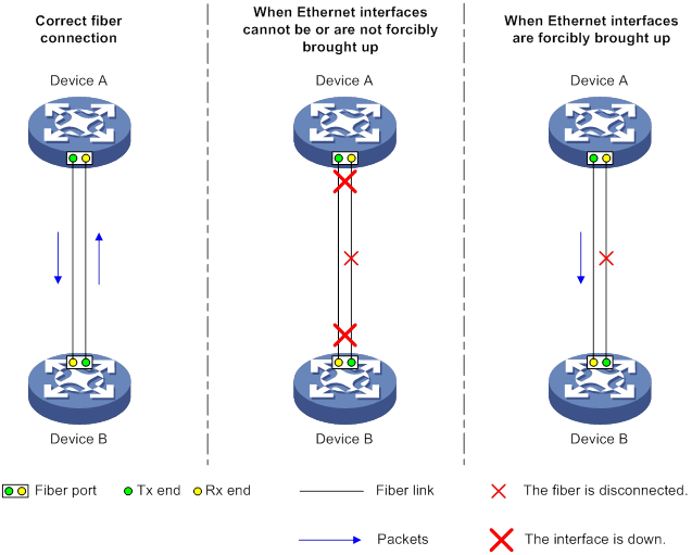
As shown in Figure 2, a fiber port uses separate fibers for transmitting and receiving packets. The physical state of the fiber port is up only when both transmit and receive fibers are physically connected. If one of the fibers is disconnected, the fiber port does not work.
To enable a fiber port to forward traffic over a single link, you can use the port up-mode command. This command forcibly brings up a fiber port, even when no fiber links or transceiver modules are present for the fiber port. When one fiber link is present and up, the fiber port can forward packets over the link unidirectionally.
Figure 2 Forcibly bring up a fiber port
Configuration restrictions and guidelines
When you forcibly bring up a fiber port, follow these restrictions and guidelines:
· The loopback, shutdown, and port up-mode commands are mutually exclusive.
· The following operations on a fiber port will cause link updown events before the port finally stays up:
? Configure both the port up-mode command and the speed or duplex command.
? Install or remove fiber links or transceiver modules after you forcibly bring up the fiber port.
Configuration procedure
To forcibly bring up a fiber port:
|
Step |
Command |
Remarks |
|
1. Enter system view. |
system-view |
N/A |
|
2. Enter Ethernet interface view. |
interface interface-type interface-number |
N/A |
|
3. Forcibly bring up the fiber port. |
port up-mode |
By default, a fiber port is not forcibly brought up, and the physical state of a fiber port depends on the physical state of the fibers. |
Configuring a Layer 3 Ethernet interface or subinterface
Setting the MTU for an Ethernet interface or subinterface
The maximum transmission unit (MTU) of an Ethernet interface affects the fragmentation and reassembly of IP packets on the interface. Typically, you do not need to modify the MTU of an interface.
To set the MTU for an Ethernet interface or subinterface:
|
Step |
Command |
Remarks |
|
1. Enter system view. |
system-view |
N/A |
|
2. Enter Ethernet interface or subinterface view. |
interface interface-type { interface-number | interface-number.subnumber } |
N/A |
|
3. Set the MTU of the Ethernet interface or subinterface. |
mtu size |
The default setting is 1500 bytes. |
Displaying and maintaining an Ethernet interface or subinterface
Execute display commands in any view and reset commands in user view.
|
Task |
Command |
|
Display interface traffic statistics. |
display counters { inbound | outbound } interface [ interface-type [ interface-number ] ] |
|
Display traffic rate statistics of interfaces in up state over the last statistics polling interval. |
display counters rate { inbound | outbound } interface [ interface-type [ interface-number ] ] |
|
Display the operational and status information of the specified interfaces. |
display interface [ interface-type [ interface-number | interface-number.subnumber ] ] [ brief [ description | down ] ] |
|
Display information about dropped packets on the specified interfaces. |
display packet-drop { interface [ interface-type [ interface-number | interface-number.subnumber ] ] | summary } |
|
Display the PFC information for an interface. |
display priority-flow-control interface [ interface-type [ interface-number ] ] |
|
Display information about storm control on the specified interfaces. |
display storm-constrain [ broadcast | multicast | unicast ] [ interface interface-type interface-number ] |
|
(In standalone mode.) Display the Ethernet module statistics. |
display ethernet statistics slot slot-number |
|
(In IRF mode.) Display the Ethernet module statistics. |
display ethernet statistics chassis chassis-number slot slot-number |
|
Clear interface or subinterface statistics. |
reset counters interface [ interface-type [ interface-number ] ] |
|
Clear the statistics of dropped packets on the specified interfaces. |
reset packet-drop interface [ interface-type [ interface-number ] ] |
|
(In standalone mode.) Clear the Ethernet module statistics. |
reset ethernet statistics [ slot slot-number ] |
|
(In IRF mode.) Clear the Ethernet module statistics. |
reset ethernet statistics [ chassis chassis-number slot slot-number ] |
Configuring loopback, null, and inloopback interfaces
This chapter describes how to configure a loopback interface, a null interface, and an inloopback interface.
Configuring a loopback interface
A loopback interface is a virtual interface. The physical layer state of a loopback interface is always up unless the loopback interface is manually shut down. Because of this benefit, loopback interfaces are widely used in the following scenarios:
· Configuring a loopback interface address as the source address of the IP packets that the device generates—Because loopback interface addresses are stable unicast addresses, they are usually used as device identifications.
? When you configure a rule on an authentication or security server to permit or deny packets that a device generates, you can simplify the rule by configuring it to permit or deny packets carrying the loopback interface address that identifies the device.
? When you use a loopback interface address as the source address of IP packets, make sure the route from the loopback interface to the peer is reachable by performing routing configuration. All data packets sent to the loopback interface are considered packets sent to the device itself, so the device does not forward these packets.
· Using a loopback interface in dynamic routing protocols—With no router ID configured for a dynamic routing protocol, the system selects the highest loopback interface IP address as the router ID. In BGP, to avoid interruption of BGP sessions due to physical port failure, you can use a loopback interface as the source interface of BGP packets.
To configure a loopback interface:
|
Step |
Command |
Remarks |
|
1. Enter system view. |
system-view |
N/A |
|
2. Create a loopback interface and enter loopback interface view. |
interface loopback interface-number |
N/A |
|
3. Configure the interface description. |
description text |
The default setting is interface name Interface (for example, LoopBack1 Interface). |
|
4. Configure the expected bandwidth of the loopback interface. |
bandwidth bandwidth-value |
By default, the expected bandwidth of a loopback interface is 0 kbps. |
|
5. Restore the default settings for the loopback interface. |
default |
N/A |
|
6. Bring up the loopback interface. |
undo shutdown |
By default, a loopback interface is up. |
Configuring a null interface
A null interface is a virtual interface and is always up, but you cannot use it to forward data packets or configure it with an IP address or link layer protocol. The null interface provides a simpler way to filter packets than ACL. You can filter undesired traffic by transmitting it to a null interface instead of applying an ACL. For example, if you specify a null interface as the next hop of a static route to a network segment, any packets routed to the network segment are dropped.
To configure a null interface:
|
Step |
Command |
Remarks |
|
1. Enter system view. |
system-view |
N/A |
|
2. Enter null interface view. |
interface null 0 |
Interface Null 0 is the default null interface on the device and cannot be manually created or removed. Only one null interface, Null 0, is supported on the device. The null interface number is always 0. |
|
3. Configure the interface description. |
description text |
The default setting is NULL0 Interface. |
|
4. Restore the default settings for the null interface. |
default |
N/A |
Configuring an inloopback interface
An inloopback interface is a virtual interface created by the system, which cannot be configured or deleted. The physical layer and link layer protocol states of an inloopback interface are always up. All IP packets sent to an inloopback interface are considered packets sent to the device itself and are not forwarded.
Displaying and maintaining loopback, null, and inloopback interfaces
Execute display commands in any view and reset commands in user view.
|
Task |
Command |
|
Display information about the specified or all loopback interfaces. |
display interface loopback [ interface-number ] [ brief [ description | down ] ] |
|
Display information about the null interface. |
display interface null [ 0 ] [ brief [ description | down ] ] |
|
Display information about the inloopback interface. |
display interface inloopback [ 0 ] [ brief [ description | down ] ] |
|
Clear the statistics on the specified or all loopback interfaces. |
reset counters interface loopback [ interface-number ] |
|
Clear the statistics on the null interface. |
reset counters interface null [ 0 ] |
Bulk configuring interfaces
Configuration restrictions and guidelines
When you bulk configure interfaces in interface range view, follow these restrictions and guidelines:
· In interface range view, only commands supported by the first interface in the specified interface list are available for configuration.
· Before you configure an interface as the first interface in an interface range, make sure you can enter the view of the interface by using the interface interface-type { interface-number | interface-number.subnumber } command.
· Do not assign both an aggregate interface and any of its member interfaces to an interface range. Some commands, after being executed on both an aggregate interface and its member interfaces, can break up the aggregation.
· Understand that the more interfaces you specify in an interface range, the longer the command execution time.
· To guarantee bulk interface configuration performance, configure fewer than 1000 interface range names.
· After a command is executed in interface range view, one of the following situations might occur:
? The system displays an error message and stays in interface range view. It means that the execution failed on one or multiple member interfaces.
- If the execution failed on the first member interface, the command is not executed on any member interfaces.
- If the execution failed on a non-first member interface, the command takes effect on the remaining member interfaces.
? The system returns to system view. It means that:
- The command is supported in both system view and interface view.
- The execution failed on a member interface in interface range view and succeeded in system view.
- The command is not executed on the subsequent member interfaces.
You can use the display this command to verify the configuration in interface view of each member interface. In addition, if the configuration in system view is not needed, use the undo form of the command to remove the configuration.
Configuration procedure
|
Step |
Command |
Remarks |
|
1. Enter system view. |
system-view |
N/A |
|
2. Enter interface range view. |
· interface range { interface-type interface-number [ to interface-type interface-number ] } &<1-24> · interface range name name [ interface { interface-type interface-number [ to interface-type interface-number ] } &<1-24> ] |
By using the interface range name command, you assign a name to an interface range and can specify this name rather than the interface range to enter the interface range view. |
|
3. (Optional.) Display commands available for the first interface in the interface range. |
Enter a question mark (?) at the interface range prompt. |
N/A |
|
4. Use available commands to configure the interfaces. |
Available commands depend on the interface. |
N/A |
|
5. (Optional.) Verify the configuration. |
display this |
N/A |
Displaying and maintaining bulk interface configuration
Execute the display command in any view.
|
Task |
Command |
|
Display information about the interface ranges created by using the interface range name command. |
display interface range [ name name ] |
Configuring the MAC address table
Overview
An Ethernet device uses a MAC address table to forward frames. A MAC address entry includes a destination MAC address, an outgoing interface, and a VLAN ID. When the device receives a frame, it uses the destination MAC address of the frame to look for a match in the MAC address table.
· The device forwards the frame out of the outgoing interface in the matching entry if a match is found.
· The device floods the frame in the VLAN of the frame if no match is found.
How a MAC address entry is created
The entries in the MAC address table include entries automatically learned by the device and entries manually added.
MAC address learning
The device can automatically populate its MAC address table by learning the source MAC addresses of incoming frames on each interface.
The device performs the following operations to learn the source MAC address of incoming packets:
1. Checks the source MAC address (for example, MAC-SOURCE) of the frame.
2. Looks up the source MAC address in the MAC address table.
? The device updates the entry if an entry is found.
? The device adds an entry for MAC-SOURCE and the incoming port if no entry is found.
When the device receives a frame destined for MAC-SOURCE after learning this source MAC address, the device performs the following operations:
3. Finds the MAC-SOURCE entry in the MAC address table.
4. Forwards the frame out of the port in the entry.
The device performs the learning process for each incoming frame with an unknown source MAC address until the table is fully populated.
Manually configuring MAC address entries
Dynamic MAC address learning does not distinguish between illegitimate and legitimate frames, which can invite security hazards. When Host A is connected to port A, a MAC address entry will be learned for the MAC address of Host A (for example, MAC A). When an illegal user sends frames with MAC A as the source MAC address to port B, the device performs the following operations:
1. Learns a new MAC address entry with port B as the outgoing interface and overwrites the old entry for MAC A.
2. Forwards frames destined for MAC A out of port B to the illegal user.
As a result, the illegal user obtains the data of Host A. To improve the security for Host A, manually configure a static entry to bind Host A to port A. Then, the frames destined for Host A are always sent out of port A. Other hosts using the forged MAC address of Host A cannot obtain the frames destined for Host A.
Types of MAC address entries
A MAC address table can contain the following types of entries:
· Static entries—A static entry is manually added to forward frames with a specific destination MAC address out of the associated interface, and it never ages out. A static entry has higher priority than a dynamically learned one.
· Dynamic entries—A dynamic entry can be manually configured or dynamically learned to forward frames with a specific destination MAC address out of the associated interface. A dynamic entry might age out. A manually configured dynamic entry has the same priority as a dynamically learned one.
· Blackhole entries—A blackhole entry is manually configured and never ages out. A blackhole entry is configured for filtering out frames with a specific source or destination MAC address. For example, to block all frames destined for or sourced from a user, you can configure the MAC address of the user as a blackhole MAC address entry. A blackhole entry has higher priority than a dynamically learned one.
· Multiport unicast entries—A multiport unicast entry is manually added to send frames with a specific unicast destination MAC address out of multiple ports, and it never ages out. A multiport unicast entry has higher priority than a dynamically learned one.
A static, blackhole, or multiport unicast MAC address entry can overwrite a dynamic MAC address entry, but not vice versa. A static entry, a blackhole entry, and a multiport unicast entry cannot overwrite one another.
Multiport unicast MAC address entries have no impact on the MAC address learning. When receiving a frame whose source MAC address matches a multiport unicast entry, the device can still learn the MAC address of the frame and generate a dynamic entry. However, the generated dynamic entry has lower priority. The device prefers to use the multiport unicast entry to forward frames destined for the MAC address in the entry.
MAC address table configuration task list
The configuration tasks discussed in the following sections can be performed in any order.
This document covers only the configuration of unicast MAC address entries, including static, dynamic, blackhole, and multiport unicast MAC address entries. For information about configuring static multicast MAC address entries, see IP Multicast Configuration Guide.
To configure the MAC address table, perform the following tasks:
|
Tasks at a glance |
|
(Optional.) Configuring MAC address entries · Adding or modifying a static or dynamic MAC address entry globally · Adding or modifying a static or dynamic MAC address entry on an interface |
|
(Optional.) Disabling MAC address learning |
|
(Optional.) Setting the aging timer for dynamic MAC address entries |
|
(Optional.) Enabling MAC address synchronization |
|
(Optional.) Configuring MAC address move notifications and suppression |
|
(Optional.) Enabling ARP fast update for MAC address moves |
|
(Optional.) Enabling MAC address learning at ingress |
|
(Optional.) Configuring the base MAC address |
|
(Optional.) Enabling SNMP notifications for the MAC address table |
Configuring MAC address entries
Configuration guidelines
· You cannot add a dynamic MAC address entry if a learned entry already exists with a different outgoing interface for the MAC address.
· The manually configured static, blackhole, and multiport unicast MAC address entries cannot survive a reboot if you do not save the configuration. The manually configured dynamic MAC address entries are lost upon reboot whether or not you save the configuration.
A frame whose source MAC address matches different types of MAC address entries is processed differently.
|
Type |
Description |
|
Static MAC address entry |
Forwards the frame according to the destination MAC address regardless of whether the frame's ingress interface is the same as that in the entry. |
|
Multiport unicast MAC address entry |
· Learns the MAC address (MACA) of the frame and generates a dynamic MAC address entry, but the generated dynamic MAC address entry does not take effect. · Forwards frames destined for MACA based on the multiport unicast MAC address entry. |
|
Blackhole MAC address entry |
Drops the frame. |
|
Dynamic MAC address entry |
· Learns the MAC address of the frames received on a different interface from that in the entry and overwrites the original entry. · Forwards the frame received on the same interface as that in the entry and updates the aging timer for the entry. |
Adding or modifying a static or dynamic MAC address entry globally
|
Step |
Command |
Remarks |
|
1. Enter system view. |
system-view |
N/A |
|
2. Add or modify a static or dynamic MAC address entry. |
mac-address { dynamic | static } mac-address interface interface-type interface-number vlan vlan-id |
By default, no MAC address entry is configured globally. Make sure you have created the VLAN and assigned the interface to the VLAN. |
Adding or modifying a static or dynamic MAC address entry on an interface
|
Step |
Command |
Remarks |
|
1. Enter system view. |
system-view |
N/A |
|
2. Enter interface view. |
·
Enter Layer 2 Ethernet interface view: ·
Enter Layer 2 aggregate interface view: |
N/A |
|
3. Add or modify a static or dynamic MAC address entry. |
mac-address { dynamic | static } mac-address vlan vlan-id |
By default, no MAC address entry is configured on the interface. Make sure you have created the VLAN and assigned the interface to the VLAN. |
Adding or modifying a blackhole MAC address entry
|
Step |
Command |
Remarks |
|
1. Enter system view. |
system-view |
N/A |
|
2. Add or modify a blackhole MAC address entry. |
mac-address blackhole mac-address vlan vlan-id |
By default, no blackhole MAC address entry is configured. Make sure you have created the VLAN. |
Adding or modifying a multiport unicast MAC address entry
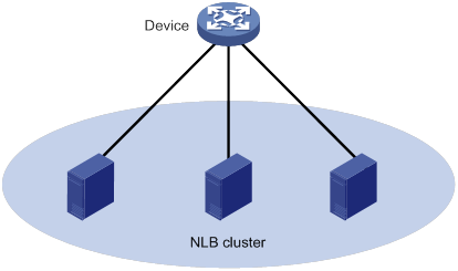
You can configure a multiport unicast MAC address entry to associate a unicast destination MAC address with multiple ports. The frame with a destination MAC address matching the entry is sent out of multiple ports.
For example, in NLB unicast mode (see Figure 3):
· All servers within a cluster uses the cluster's MAC address as their own address.
· Frames destined for the cluster are forwarded to every server in the group.
In this case, you can configure a multiport unicast MAC address entry on the device connected to the server group. Then, the device forwards the frame destined for the server group to every server through all ports connected to the servers within the cluster.
You can configure a multiport unicast MAC address entry globally or on an interface.
Configuring a multiport unicast MAC address entry globally
|
Step |
Command |
Remarks |
|
1. Enter system view. |
system-view |
N/A |
|
2. Add or modify a multiport unicast MAC address entry. |
mac-address multiport mac-address interface interface-list vlan vlan-id |
By default, no multiport unicast MAC address entry is configured globally. Make sure you have created the VLAN and assigned the interface to the VLAN. |
Configuring a multiport unicast MAC address entry on an interface
|
Step |
Command |
Remarks |
|
1. Enter system view. |
system-view |
N/A |
|
2. Enter interface view. |
·
Enter Layer 2 Ethernet interface view: ·
Enter Layer 2 aggregate interface view: |
N/A |
|
3. Add the interface to a multiport unicast MAC address entry. |
mac-address multiport mac-address vlan vlan-id |
By default, no multiport unicast MAC address entry is configured on the interface. Make sure you have created the VLAN and assigned the interface to the VLAN. |
Disabling MAC address learning
MAC address learning is enabled by default. To prevent the MAC address table from being saturated when the device is experiencing attacks, disable MAC address learning. For example, you can disable MAC address learning to prevent the device from being attacked by a large amount of frames with different source MAC addresses.
After MAC address learning is disabled, the device immediately deletes existing dynamic MAC address entries.
Disabling global MAC address learning
Global MAC address learning does not take effect on a VXLAN VSI. For information about VXLAN VSIs, see VXLAN Configuration Guide.
To disable global MAC address learning:
|
Step |
Command |
Remarks |
|
1. Enter system view. |
system-view |
N/A |
|
2. Disable global MAC address learning. |
undo mac-address mac-learning enable |
By default, global MAC address learning is enabled. |
Disabling MAC address learning on interfaces
When global MAC address learning is enabled, you can disable MAC address learning on a single interface.
To disable MAC address learning on an interface:
|
Step |
Command |
Remarks |
|
1. Enter system view. |
system-view |
N/A |
|
2. Enter interface view. |
·
Enter Layer 2 Ethernet interface view: ·
Enter Layer 2 aggregate interface view: |
N/A |
|
3. Disable MAC address learning on the interface. |
undo mac-address mac-learning enable |
By default, MAC address learning on the interface is enabled. |
Setting the aging timer for dynamic MAC address entries
For security and efficient use of table space, the MAC address table uses an aging timer for each dynamic MAC address entry. If a dynamic MAC address entry is not updated before the aging timer expires, the device deletes the entry. This aging mechanism ensures that the MAC address table can promptly update to accommodate latest network topology changes.
A stable network requires a longer aging interval, and an unstable network requires a shorter aging interval.
An aging interval that is too long might cause the MAC address table to retain outdated entries. As a result, the MAC address table resources might be exhausted, and the MAC address table might fail to update its entries to accommodate the latest network changes.
An interval that is too short might result in removal of valid entries, which would cause unnecessary floods and possibly affect the device performance.
To reduce floods on a stable network, set a long aging timer or disable the timer to prevent dynamic entries from unnecessarily aging out. Reducing floods improves the network performance. Reducing flooding also improves the security because it reduces the chances for a data frame to reach unintended destinations.
To set the aging timer for dynamic MAC address entries:
|
Step |
Command |
Remarks |
|
1. Enter system view. |
system-view |
N/A |
|
2. Set the aging timer for dynamic MAC address entries. |
mac-address timer { aging seconds | no-aging } |
The default setting is 300 seconds. The no-aging keyword disables the aging timer. |
Enabling MAC address synchronization
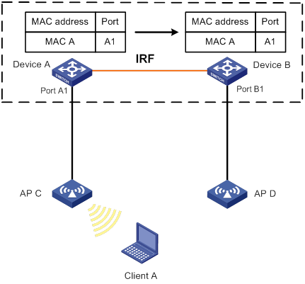
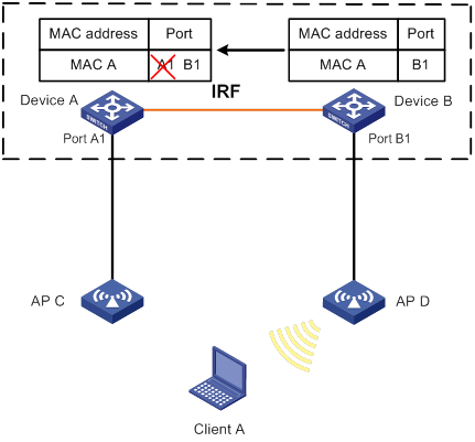
To avoid unnecessary floods and improve forwarding speed, make sure all cards have the same MAC address table. After you enable MAC address synchronization, each card advertises learned MAC address entries to other cards. After you enable MAC address synchronization on an IRF fabric, each card advertises learned MAC address entries to other cards of all member devices.
As shown in Figure 4:
· Device A and Device B form an IRF fabric enabled with MAC address synchronization.
· Device A and Device B connect to AP C and AP D, respectively.
When Client A associates with AP C, Device A learns a MAC address entry for Client A and advertises it to Device B.
Figure 4 MAC address tables of devices when Client A accesses AP C
When Client A roams to AP D, Device B learns a MAC address entry for Client A. Device B advertises it to Device A to ensure service continuity for Client A, as shown in Figure 5.
Figure 5 MAC address tables of devices when Client A roams to AP D
To enable MAC address synchronization:
|
Step |
Command |
Remarks |
|
1. Enter system view. |
system-view |
N/A |
|
2. Enable MAC address synchronization. |
mac-address mac-roaming enable |
By default, MAC address synchronization is disabled. |
Configuring MAC address move notifications and suppression
The outgoing interface for a MAC address entry learned on interface A is changed to interface B when the following conditions exist:
· Interface B receives a packet with the MAC address as the source MAC address.
· Interface B belongs to the same VLAN as interface A.
In this case, the MAC address is moved from interface A to interface B, and a MAC address move occurs.
The MAC address move notifications feature enables the device to output MAC address move logs when MAC address moves are detected.
If a MAC address is continuously moved between the two interfaces, Layer 2 loops might occur. To detect and locate loops, you can view the MAC address move information. To display the MAC address move records after the device is started, use the display mac-address mac-move command.
If the system detects that MAC address moves occur frequently on an interface, you can configure MAC address move suppression to shut the interface down. The interface automatically goes up after a suppression interval. Or, you can manually bring up the interface.
The MAC address move suppression feature must work with the ARP fast update for MAC address moves feature. For information about ARP fast update for MAC address moves, see "Enabling ARP fast update for MAC address moves."
To configure MAC address move notifications and MAC address move suppression:
|
Step |
Command |
Remarks |
|
1. Enter system view. |
system-view |
N/A |
|
2. Enable MAC address move notifications and optionally specify a MAC move detection interval. |
mac-address notification mac-move [ interval interval ] |
By default, MAC address move notifications are disabled. If you do not specify a detection interval, the default setting of 1 minute is used. After you execute this command, the system sends only log messages to the information center module. If the device is also configured with the snmp-agent trap enable mac-address command, the system also sends SNMP notifications to the SNMP module. |
|
3. (Optional.) Set MAC address move suppression parameters. |
mac-address notification mac-move suppression { interval interval | threshold threshold } |
By default, the suppression interval is 30 seconds, and the suppression threshold is 3. |
|
4. Enter interface view. |
·
Enter Layer 2 Ethernet interface view: ·
Enter Layer 2 aggregate interface view: |
N/A |
|
5. Enable MAC address move suppression. |
mac-address notification mac-move suppression |
By default, MAC address move suppression is disabled. |
|
6. Return to system view. |
quit |
N/A |
|
7. Enable ARP fast update for MAC address moves. |
mac-address mac-move fast-update |
By default, ARP fast update for MAC address moves is disabled. |
Enabling ARP fast update for MAC address moves
ARP fast update for MAC address moves allows the device to update an ARP entry immediately after the outgoing interface for a MAC address changes. This feature ensures data connection without interruption.
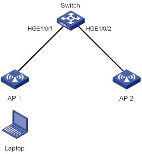
As shown in Figure 6, a mobile user laptop accesses the network by connecting to AP 1 or AP 2. When the AP to which the user connects changes, the switch updates the ARP entry for the user immediately after it detects a MAC address move.
Figure 6 ARP fast update application scenario
To enable ARP fast update for MAC address moves:
|
Step |
Command |
Remarks |
|
1. Enter system view. |
system-view |
N/A |
|
2. Enable ARP fast update for MAC address moves. |
mac-address mac-move fast-update |
By default, ARP fast update for MAC address moves is disabled. |
Enabling MAC address learning at ingress
The device can learn the source MAC address of a packet when it receives the packet or when it sends out the packet.
Some devices learn MAC address at egress. The devices cannot learn MAC addresses if no egress interfaces correspond to received packets. To avoid unnecessary broadcast traffic, enable MAC address learning at ingress on the devices. The devices then can learn the source MAC address at ingress before a packet is forwarded.
To enable MAC address learning at ingress:
|
Step |
Command |
Remarks |
|
1. Enter system view. |
system-view |
N/A |
|
2. Enable MAC address learning at ingress. |
mac-address mac-learning ingress |
By default, the device learns MAC addresses at egress. |
Configuring the base MAC address
The base MAC address is the start MAC address of the 90 consecutive MAC addresses that are reserved for system use. The base MAC address determines the higher 36 bits of the reserved MAC addresses and the MAC addresses that can be assigned to Layer 3 interfaces.
When you configure the base MAC address, make sure the base MAC address plus 90 (decimal) produces a MAC address that has the same higher 36 bits. When you assign a MAC address to a Layer 3 interface, make sure the following requirements are met:
· The MAC address must have the same higher 36 bits as the base MAC address.
· The MAC address must be no lower than the base MAC address plus 90 (decimal).
To configure the base MAC address:
|
Step |
Command |
Remarks |
|
1. Enter system view. |
system-view |
N/A |
|
2. Configure the base MAC address. |
routing-interface base-mac mac-address |
By default, no base MAC address exists. |
Enabling SNMP notifications for the MAC address table
To report critical MAC address move events to an NMS, enable SNMP notifications for the MAC address table. For MAC address move event notifications to be sent correctly, you must also configure SNMP on the device.
When SNMP notifications are disabled for the MAC address table, the device sends the generated logs to the information center. To display the logs, configure the log destination and output rule configuration in the information center.
For more information about SNMP and information center configuration, see the network management and monitoring configuration guide for the device.
To enable SNMP notifications for the MAC address table:
|
Step |
Command |
Remarks |
|
1. Enter system view. |
system-view |
N/A |
|
2. Enable SNMP notifications for the MAC address table. |
snmp-agent trap enable mac-address [ mac-move ] |
By default, SNMP notifications are enabled for the MAC address table. When SNMP notifications are disabled for the MAC address table, syslog messages are sent to notify important events on the MAC address table module. |
Displaying and maintaining the MAC address table
Execute display commands in any view.
|
Task |
Command |
|
Display MAC address table information. |
display mac-address [ mac-address [ vlan vlan-id ] | [ [ dynamic | static ] [ interface interface-type interface-number ] | blackhole | multiport ] [ vlan vlan-id ] [ count ] ] |
|
Display the aging timer for dynamic MAC address entries. |
display mac-address aging-time |
|
Display the system or interface MAC address learning state. |
display mac-address mac-learning [ interface interface-type interface-number ] |
|
Display MAC address statistics. |
display mac-address statistics |
|
(In standalone mode.) Display the MAC address move records. |
display mac-address mac-move [ slot slot-number ] |
|
(In IRF mode.) Display the MAC address move records. |
display mac-address mac-move [ chassis chassis-number slot slot-number ] |
MAC address table configuration example
Network requirements
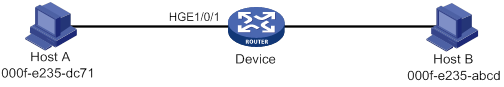
As shown in Figure 7:
· Host A at MAC address 000f-e235-dc71 is connected to HundredGigE 1/0/1 of Device and belongs to VLAN 1.
· Host B at MAC address 000f-e235-abcd, which behaved suspiciously on the network, also belongs to VLAN 1.
Configure the MAC address table as follows:
· To prevent MAC address spoofing, add a static entry for Host A in the MAC address table of Device.
· To drop all frames destined for Host B, add a blackhole MAC address entry for Host B.
· Set the aging timer to 500 seconds for dynamic MAC address entries.
Configuration procedure
# Add a static MAC address entry for MAC address 000f-e235-dc71 on HundredGigE 1/0/1 that belongs to VLAN 1.
<Device> system-view
[Device] mac-address static 000f-e235-dc71 interface hundredgige 1/0/1 vlan 1
# Add a blackhole MAC address entry for MAC address 000f-e235-abcd that belongs to VLAN 1.
[Device] mac-address blackhole 000f-e235-abcd vlan 1
# Set the aging timer to 500 seconds for dynamic MAC address entries.
[Device] mac-address timer aging 500
Verifying the configuration
# Display the static MAC address entries for HundredGigE 1/0/1.
[Device] display mac-address static interface hundredgige 1/0/1
MAC Address VLAN ID State Port/NickName Aging
000f-e235-dc71 1 Static HGE1/0/1 N
# Display the blackhole MAC address entries.
[Device] display mac-address blackhole
MAC Address VLAN ID State Port/NickName Aging
000f-e235-abcd 1 Blackhole N/A N
# Display the aging time of dynamic MAC address entries.
[Device] display mac-address aging-time
MAC address aging time: 500s.
Configuring MAC Information
The MAC Information feature can generate syslog messages or SNMP notifications when MAC address entries are learned or deleted. You can use these messages to monitor user's leaving or joining the network and analyze network traffic.
The MAC Information feature buffers the MAC change syslog messages or SNMP notifications in a queue. The device overwrites the oldest MAC address change written into the queue with the most recent MAC address change when the following conditions exist:
· The MAC change notification interval does not expire.
· The queue has been exhausted.
To send a syslog message or SNMP notification immediately after it is created, set the queue length to zero.
Enabling MAC Information
|
Step |
Command |
Remarks |
|
1. Enter system view. |
system-view |
N/A |
|
2. Enable MAC Information globally. |
mac-address information enable |
By default, MAC Information is globally disabled. |
|
3. Enter Layer 2 Ethernet interface view. |
interface interface-type interface-number |
N/A |
|
4. Enable MAC Information on the interface. |
mac-address information enable { added | deleted } |
By default, MAC Information is disabled on the interface. Make sure you have enabled MAC Information globally before you enable it on the interface. |
Configuring the MAC Information mode
The following MAC Information modes are available for sending MAC address changes:
· Syslog—The device sends syslog messages to notify MAC address changes. The device sends syslog messages to the information center, which then outputs them to the monitoring terminal. For more information about information center, see Network Management and Monitoring Configuration Guide.
· Trap—The device sends SNMP notifications to notify MAC address changes. The device sends SNMP notifications to the NMS. For more information about SNMP, see Network Management and Monitoring Configuration Guide.
To configure the MAC Information mode:
|
Step |
Command |
Remarks |
|
1. Enter system view. |
system-view |
N/A |
|
2. Configure the MAC Information mode. |
mac-address information mode { syslog | trap } |
The default setting is trap. |
Setting the MAC change notification interval
To prevent syslog messages or SNMP notifications from being sent too frequently, you can set the MAC change notification interval to a larger value.
To set the MAC change notification interval:
|
Step |
Command |
Remarks |
|
1. Enter system view. |
system-view |
N/A |
|
2. Set the MAC change notification interval. |
mac-address information interval interval |
The default setting is 1 second. |
Setting the MAC Information queue length
|
Step |
Command |
Remarks |
|
1. Enter system view. |
system-view |
N/A |
|
2. Set the MAC Information queue length. |
mac-address information queue-length value |
The default setting is 50. |
MAC Information configuration example
Network requirements
Enable MAC Information on HundredGigE 1/0/1 on Device in Figure 8 to send MAC address changes in syslog messages to the log host, Host B, through interface HundredGigE 1/0/2.
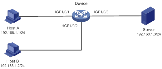
Configuration restrictions and guidelines
When you edit the file /etc/syslog.conf, follow these restrictions and guidelines:
· Comments must be on a separate line and must begin with a pound sign (#).
· No redundant spaces are allowed after the file name.
· The logging facility name and the severity level specified in the /etc/syslog.conf file must be the same as those configured on the device. Otherwise, the log information might not be output correctly to the log host. The logging facility name and the severity level are configured by using the info-center loghost and info-center source commands, respectively.
Configuration procedure
1. Configure Device to send syslog messages to Host B:
# Enable the information center.
<Device> system-view
[Device] info-center enable
# Specify the log host 192.168.1.2/24 and specify local4 as the logging facility.
[Device] info-center loghost 192.168.1.2 facility local4
# Disable log output to the log host.
[Device] info-center source default loghost deny
To avoid output of unnecessary information, disable all modules from outputting logs to the specified destination (loghost, in this example) before you configure an output rule.
# Configure an output rule to output to the log host MAC address logs that have a severity level no lower than informational.
[Device] info-center source mac loghost level informational
2. Configure the log host, Host B:
Configure Solaris as follows. Configure other UNIX operating systems in the same way Solaris is configured.
a. Log in to the log host as a root user.
b. Create a subdirectory named Device in directory /var/log/.
# mkdir /var/log/Device
c. Create file info.log in the Device directory to save logs from Device.
# touch /var/log/Device/info.log
d. Edit the file syslog.conf in directory /etc/ and add the following contents:
# Device configuration messages
local4.info /var/log/Device/info.log
In this configuration, local4 is the name of the logging facility that the log host uses to receive logs, and info is the informational level. The UNIX system records the log information that has a severity level no lower than informational to the file /var/log/Device/info.log.
e. Display the process ID of syslogd, end the syslogd process, and then restart syslogd using the –r option to make the new configuration take effect.
# ps -ae | grep syslogd
147
# kill -HUP 147
# syslogd -r &
The device can output MAC address logs to the log host, which stores the logs to the specified file.
3. Enable MAC Information on Device:
# Enable MAC Information globally.
[Device] mac-address information enable
# Configure the MAC Information mode as syslog.
[Device] mac-address information mode syslog
# Enable MAC Information on HundredGigE 1/0/1 to enable the port to record MAC address change information when the interface performs either of the following operations:
? Learns a new MAC address.
? Deletes an existing MAC address.
[Device] interface hundredgige 1/0/1
[Device-HundredGigE1/0/1] mac-address information enable added
[Device-HundredGigE1/0/1] mac-address information enable deleted
[Device-HundredGigE1/0/1] quit
# Set the MAC Information queue length to 100.
[Device] mac-address information queue-length 100
# Set the MAC change notification interval to 20 seconds.
[Device] mac-address information interval 20
Configuring Ethernet link aggregation
Ethernet link aggregation bundles multiple physical Ethernet links into one logical link, called an aggregate link.
Link aggregation has the following benefits:
· Increased bandwidth beyond the limits of any single link. In an aggregate link, traffic is distributed across the member ports.
· Improved link reliability. The member ports dynamically back up one another. When a member port fails, its traffic is automatically switched to other member ports.
As shown in Figure 9, Device A and Device B are connected by three physical Ethernet links. These physical Ethernet links are combined into an aggregate link called link aggregation 1. The bandwidth of this aggregate link can reach up to the total bandwidth of the three physical Ethernet links. At the same time, the three Ethernet links back up one another. When a physical Ethernet link fails, the traffic previously transmitted on the failed link is switched to the other two links.
Figure 9 Ethernet link aggregation diagram
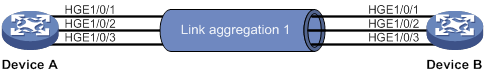
Basic concepts
Aggregation group, member port, and aggregate interface
An aggregation group is a group of Ethernet interfaces bundled together. These Ethernet interfaces are called member ports of the aggregation group. Each aggregation group has a corresponding logical interface called an aggregate interface.
When an aggregate interface is created, the device automatically creates an aggregation group of the same type and number as the aggregate interface.
An aggregate interface can be one of the following types:
· Layer 2—A Layer 2 aggregate interface is created manually. The member ports of the corresponding Layer 2 aggregation group can only be Layer 2 Ethernet interfaces.
· Layer 3—A Layer 3 aggregate interface is created manually. The member ports of the corresponding Layer 3 aggregation group can only be Layer 3 Ethernet interfaces.
On a Layer 3 aggregate interface, you can create subinterfaces.
The port rate of an aggregate interface equals the total rate of its Selected member ports. Its duplex mode is the same as that of the Selected member ports. For more information about Selected member ports, see "Aggregation states of member ports in an aggregation group."
Aggregation states of member ports in an aggregation group
A member port in an aggregation group can be in any of the following aggregation states:
· Selected—A Selected port can forward traffic.
· Unselected—An Unselected port cannot forward traffic.
· Individual—An Individual port can forward traffic as a normal physical port. A port is placed in the Individual state when the following conditions exist:
? Its aggregate interface is configured as an edge aggregate interface.
? The port has not received Link Aggregation Control Protocol Data Units (LACPDUs) from its peer port.
Operational key
When aggregating ports, the system automatically assigns each port an operational key based on port information, such as port rate and duplex mode. Any change to this information triggers a recalculation of the operational key.
In an aggregation group, all Selected ports have the same operational key.
Configuration types
Port configurations include attribute configurations and protocol configurations. Attribute configurations of a link aggregation member port affect its aggregation state.
· Attribute configurations—To become a Selected port, a member port must have the same attribute configurations as the aggregate interface. Table 2 describes the attribute configurations.
Attribute configuration changes on an aggregate interface are automatically synchronized to all member ports. If the device fails to synchronize the changes to a Selected port, the port might become Unselected. For the port to become Selected again, you can modify the attribute configurations on the aggregate interface or the port. The synchronization failure does not affect the attribute configuration changes made on the aggregate interface. The configurations that have been synchronized from the aggregate interface are retained on the member ports even after the aggregate interface is deleted.
Any attribute configuration change on a member port might affect the aggregation states and running services of the member ports. The system displays a warning message every time you try to change an attribute configuration setting on a member port.
Table 2 Attribute configurations
|
Feature |
Considerations |
|
Port isolation |
Indicates whether the port has joined an isolation group and which isolation group the port belongs to. |
|
VLAN mapping |
VLAN mapping configured on the port. For more information about VLAN mapping, see "Configuring VLAN mapping." |
|
VLAN |
VLAN attribute configurations include the following: · Permitted VLAN IDs. · PVID. · Link type (trunk, hybrid, or access). · VLAN tagging mode. For information about VLANs, see "Configuring VLANs." |
· Protocol configurations—Protocol configurations of a member port do not affect the aggregation state of the member port. MAC address learning and spanning tree settings are examples of protocol configurations.
|
|
NOTE: · The protocol configurations for an aggregate interface take effect only on the current aggregate interface. · The protocol configurations for a member port take effect only when the port leaves its aggregation group. |
Link aggregation modes
An aggregation group operates in one of the following modes:
· Static—Static aggregation is stable. An aggregation group in static mode is called a static aggregation group. The aggregation states of the member ports in a static aggregation group are not affected by the peer ports.
· Dynamic—An aggregation group in dynamic mode is called a dynamic aggregation group. The local system and the peer system automatically maintain the aggregation states of the member ports. Dynamic link aggregation reduces the administrators' workload.
Aggregating links in static mode
Choosing a reference port
When setting the aggregation states of the ports in an aggregation group, the system automatically chooses a member port as the reference port. A Selected port must have the same operational key and attribute configurations as the reference port.
The system chooses a reference port from the member ports in up state.
The candidate reference ports are organized into different priority levels following these rules:
1. In descending order of port priority.
2. Full duplex.
3. In descending order of speed.
4. Half duplex.
5. In descending order of speed.
From the candidate ports with the same attribute configurations as the aggregate interface, the one with the highest priority level is chosen as the reference port.
· If multiple ports have the same priority level, the port that has been Selected (if any) is chosen. If multiple ports with the same priority level have been Selected, the one with the smallest port number is chosen.
· If multiple ports have the same priority level and none of them has been Selected, the port with the smallest port number is chosen.
Setting the aggregation state of each member port
After the reference port is chosen, the system sets the aggregation state of each member port in the static aggregation group.
Figure 10 Setting the aggregation state of a member port in a static aggregation group
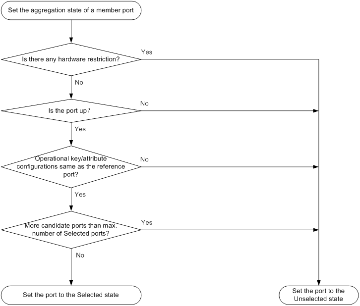
After the limit on Selected ports is reached, the aggregation state of a new member port varies by following conditions:
· The port is placed in Unselected state if the port and the Selected ports have the same port priority. This mechanism prevents traffic interruption on the existing Selected ports. A device reboot can cause the device to recalculate the aggregation states of member ports.
· The port is placed in Selected state when the following conditions are met:
? The port and the Selected ports have different port priorities, and the port has a higher port priority than a minimum of one Selected port.
? The port has the same attribute configurations as the aggregate interface.
Any operational key or attribute configuration change might affect the aggregation states of link aggregation member ports.
Aggregating links in dynamic mode
Dynamic aggregation is implemented through IEEE 802.3ad Link Aggregation Control Protocol (LACP).
LACP
LACP uses LACPDUs to exchange aggregation information between LACP-enabled devices. Each member port in a dynamic aggregation group can exchange information with its peer. When a member port receives an LACPDU, it compares the received information with information received on the other member ports. In this way, the two systems reach an agreement on which ports are placed in Selected state.
LACP functions
LACP offers basic LACP functions and extended LACP functions, as described in Table 3.
Table 3 Basic and extended LACP functions
|
Category |
Description |
|
Basic LACP functions |
Implemented through the basic LACPDU fields, including the system LACP priority, system MAC address, port priority, port number, and operational key. |
|
Extended LACP functions |
Implemented by extending the LACPDU with new TLV fields. Extended LACP can implement LACP MAD for the IRF feature. The switch series can participate in LACP MAD as either an IRF member device or an intermediate device. For more information about IRF and the LACP MAD mechanism, see IRF Configuration Guide. |
LACP operating modes
LACP can operate in active or passive mode.
When LACP is operating in passive mode on a local member port and its peer port, both ports cannot send LACPDUs. When LACP is operating in active mode on either end of a link, both ports can send LACPDUs.
LACP priorities
LACP priorities include system LACP priority and port priority, as described in Table 4. The smaller the priority value, the higher the priority.
|
Type |
Description |
|
System LACP priority |
Used by two peer devices (or systems) to determine which one is superior in link aggregation. In dynamic link aggregation, the system that has higher system LACP priority sets the Selected state of member ports on its side. The system that has lower priority sets the aggregation state of local member ports the same as their respective peer ports. |
|
Port priority |
Determines the likelihood of a member port to be a Selected port on a system. A port with a higher port priority is more likely to become Selected. |
LACP timeout interval
The LACP timeout interval specifies how long a member port waits to receive LACPDUs from the peer port. If a local member port has not received LACPDUs from the peer within the LACP timeout interval, the member port considers the peer as failed.
The LACP timeout interval also determines the LACPDU sending rate of the peer. LACP timeout intervals include the following types:
· Short timeout interval—3 seconds. If you use the short timeout interval, the peer sends one LACPDU per second.
· Long timeout interval—90 seconds. If you use the long timeout interval, the peer sends one LACPDU every 30 seconds.
How dynamic link aggregation works
Choosing a reference port
The system chooses a reference port from the member ports in up state. A Selected port must have the same operational key and attribute configurations as the reference port.
The local system (the actor) and the peer system (the partner) negotiate a reference port by using the following workflow:
1. The two systems determine the system with the smaller system ID.
A system ID contains the system LACP priority and the system MAC address.
a. The two systems compare their LACP priority values.
The lower the LACP priority, the smaller the system ID. If the LACP priority values are the same, the two systems proceed to step b.
b. The two systems compare their MAC addresses.
The lower the MAC address, the smaller the system ID.
2. The system with the smaller system ID chooses the port with the smallest port ID as the reference port.
A port ID contains a port priority and a port number. The lower the port priority, the smaller the port ID.
a. The system chooses the port with the lowest priority value as the reference port.
If the ports have the same priority, the system proceeds to step b.
b. The system compares their port numbers.
The smaller the port number, the smaller the port ID.
The port with the smallest port number and the same attribute configurations as the aggregate interface is chosen as the reference port.
Setting the aggregation state of each member port
After the reference port is chosen, the system with the smaller system ID sets the state of each member port on its side.
Figure 11 Setting the state of a member port in a dynamic aggregation group
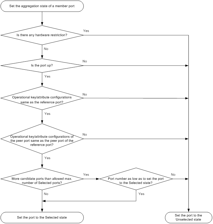
The system with the greater system ID can detect the aggregation state changes on the peer system. The system with the greater system ID sets the aggregation state of local member ports the same as their peer ports.
When you aggregate interfaces in dynamic mode, follow these guidelines:
· A dynamic link aggregation group chooses only full-duplex ports as the Selected ports.
· For stable aggregation and service continuity, do not change the operational key or attribute configurations on any member port.
· After the Selected port limit is reached, a newly joining port becomes a Selected port if it is more eligible than a current Selected port.
Edge aggregate interface
Dynamic link aggregation fails on a server-facing aggregate interface if dynamic link aggregation is configured only on the device. The device forwards traffic by using only one of the physical ports that are connected to the server.
To improve link reliability, configure the aggregate interface as an edge aggregate interface. This feature enables all member ports of the aggregation group to forward traffic. When a member port fails, its traffic is automatically switched to other member ports.
After dynamic link aggregation is configured on the server, the device can receive LACPDUs from the server. Then, link aggregation between the device and the server operates correctly.
An edge aggregate interface takes effect only when it is configured on an aggregate interface corresponding to a dynamic aggregation group.
Load sharing modes for link aggregation groups
In a link aggregation group, traffic can be load shared across the Selected ports based on any of the following modes:
· Per-flow load sharing—Load shares traffic on a per-flow basis. The load sharing mode classifies packets into flows and forwards packets of the same flow on the same link. This mode can be one or any combination of the following traffic classification criteria:
? Ingress port.
? Source or destination IP address.
? Source or destination MAC address.
? Source or destination port number.
? Protocol number.
· Per-packet load sharing—Load shares traffic on a per-packet basis.
Ethernet link aggregation configuration task list
|
Tasks at a glance |
|
(Required.) Configuring an aggregation group: |
|
(Optional.) Configuring an aggregate interface: · Configuring the description of an aggregate interface · Setting the MAC address for an aggregate interface · Specifying ignored VLANs for a Layer 2 aggregate interface · Setting the MTU for a Layer 3 aggregate interface · Setting the minimum and maximum numbers of Selected ports for an aggregation group · Setting the expected bandwidth for an aggregate interface · Configuring an edge aggregate interface · Enabling BFD for an aggregation group |
|
(Optional.) Configuring load sharing for link aggregation groups: · Setting load sharing modes for link aggregation groups · Enabling local-first load sharing for link aggregation · Configuring link aggregation load sharing algorithm settings |
|
(Optional.) Enabling link-aggregation traffic redirection |
|
(Optional.) Configuring the link aggregation capability for the device |
Configuring an aggregation group
This section explains how to configure an aggregation group.
Configuration restrictions and guidelines
When you configure an aggregation group, follow these restrictions and guidelines:
· Do not assign a reflector port for port mirroring to an aggregation group. For more information about reflector ports, see Network Management and Monitoring Configuration Guide.
· Deleting an aggregate interface also deletes its aggregation group and causes all member ports to leave the aggregation group.
· You must configure the same aggregation mode on the two ends of an aggregate link.
· For a successful static aggregation, make sure the ports at both ends of each link are in the same aggregation state.
· For a successful dynamic aggregation, make sure the peer ports of the ports aggregated at one end are also aggregated. The two ends can automatically negotiate the aggregation state of each member port.
Configuring a Layer 2 aggregation group
Configuring a Layer 2 static aggregation group
|
Step |
Command |
Remarks |
|
1. Enter system view. |
system-view |
N/A |
|
2. Create a Layer 2 aggregate interface and enter Layer 2 aggregate interface view. |
interface bridge-aggregation interface-number |
When you create a Layer 2 aggregate interface, the system automatically creates a Layer 2 static aggregation group numbered the same. |
|
3. Exit to system view. |
quit |
N/A |
|
4. Assign an interface to the specified Layer 2 aggregation group. |
a
Enter Layer 2 Ethernet interface view: b
Assign the interface to the specified
Layer 2 aggregation group: |
Repeat these two substeps to assign more Layer 2 Ethernet interfaces to the aggregation group. |
|
5. (Optional.) Set the port priority for the interface. |
link-aggregation port-priority priority |
The default port priority of an interface is 32768. |
Configuring a Layer 2 dynamic aggregation group
|
Step |
Command |
Remarks |
|
1. Enter system view. |
system-view |
N/A |
|
2. Set the system LACP priority. |
lacp system-priority priority |
By default, the system LACP priority is 32768. Changing the system LACP priority might affect the aggregation states of the ports in a dynamic aggregation group. |
|
3. Create a Layer 2 aggregate interface and enter Layer 2 aggregate interface view. |
interface bridge-aggregation interface-number |
When you create a Layer 2 aggregate interface, the system automatically creates a Layer 2 static aggregation group numbered the same. |
|
4. Configure the aggregation group to operate in dynamic mode. |
link-aggregation mode dynamic |
By default, an aggregation group operates in static mode. |
|
5. Exit to system view. |
quit |
N/A |
|
6. Assign an interface to the specified Layer 2 aggregation group. |
a
Enter Layer 2 Ethernet interface view: b
Assign the interface to the specified
Layer 2 aggregation group: |
Repeat these two substeps to assign more Layer 2 Ethernet interfaces to the aggregation group. |
|
7. Set the LACP operating mode for the interface. |
·
Set the LACP operating mode to passive: ·
Set the LACP operating mode to active: |
By default, LACP is operating in active mode. |
|
8. Set the port priority for the interface. |
link-aggregation port-priority priority |
The default setting is 32768. |
|
9. Set the short LACP timeout interval (3 seconds) for the interface. |
lacp period short |
By default, the long LACP timeout interval (90 seconds) is used by the interface. To avoid traffic interruption during an ISSU, do not set the short LACP timeout interval before performing the ISSU. For more information about ISSU, see Fundamentals Configuration Guide. |
Configuring a Layer 3 aggregation group
Configuring a Layer 3 static aggregation group
|
Step |
Command |
Remarks |
|
1. Enter system view. |
system-view |
N/A |
|
2. Create a Layer 3 aggregate interface and enter Layer 3 aggregate interface view. |
interface route-aggregation interface-number |
When you create a Layer 3 aggregate interface, the system automatically creates a Layer 3 static aggregation group numbered the same. |
|
3. Exit to system view. |
quit |
N/A |
|
4. Assign an interface to the specified Layer 3 aggregation group. |
a
Enter Layer 3 Ethernet interface view: b
Assign the interface to the specified
Layer 3 aggregation group: |
Repeat these two substeps to assign more Layer 3 Ethernet interfaces to the aggregation group. |
|
5. (Optional.) Set the port priority for the interface. |
link-aggregation port-priority priority |
The default port priority of an interface is 32768. |
Configuring a Layer 3 dynamic aggregation group
|
Step |
Command |
Remarks |
|
1. Enter system view. |
system-view |
N/A |
|
2. Set the system LACP priority. |
lacp system-priority priority |
By default, the system LACP priority is 32768. Changing the system LACP priority might affect the aggregation states of the ports in the dynamic aggregation group. |
|
3. Create a Layer 3 aggregate interface and enter Layer 3 aggregate interface view. |
interface route-aggregation interface-number |
When you create a Layer 3 aggregate interface, the system automatically creates a Layer 3 static aggregation group numbered the same. |
|
4. Configure the aggregation group to operate in dynamic mode. |
link-aggregation mode dynamic |
By default, an aggregation group operates in static mode. |
|
5. Exit to system view. |
quit |
N/A |
|
6. Assign an interface to the specified Layer 3 aggregation group. |
a
Enter Layer 3 Ethernet interface view: b
Assign the interface to the specified
Layer 3 aggregation group: |
Repeat these two substeps to assign more Layer 3 Ethernet interfaces to the aggregation group. |
|
7. Set the LACP operating mode for the interface. |
·
Set the LACP operating mode to passive: ·
Set the LACP operating mode to active: |
By default, LACP is operating in active mode. |
|
8. Set the port priority for the interface. |
link-aggregation port-priority priority |
The default setting is 32768. |
|
9. Set the short LACP timeout interval (3 seconds) for the interface. |
lacp period short |
By default, the long LACP timeout interval (90 seconds) is used by the interface. To avoid traffic interruption during an ISSU, do not set the short LACP timeout interval before performing the ISSU. For more information about ISSU, see Fundamentals Configuration Guide. |
Configuring an aggregate interface
Most configurations that can be made on Layer 2 or Layer 3 Ethernet interfaces can also be made on Layer 2 or Layer 3 aggregate interfaces.
Configuring the description of an aggregate interface
You can configure the description of an aggregate interface for administration purposes, for example, describing the purpose of the interface.
To configure the description of an aggregate interface:
|
Step |
Command |
Remarks |
|
1. Enter system view. |
system-view |
N/A |
|
2. Enter aggregate interface or subinterface view. |
·
Enter Layer 2 aggregate interface view: ·
Enter Layer 3 aggregate interface or
subinterface view: |
N/A |
|
3. Configure the description of the aggregate interface or subinterface. |
description text |
By default, the description of an interface is interface-name Interface. |
Setting the MAC address for an aggregate interface
Typically, all aggregate interfaces on a device use the same MAC address, and aggregate interfaces on different devices use different MAC addresses. However, you must set different MAC addresses for aggregate interfaces on a device in some situations.
For example, in a spanning tree network, the BPDUs sent by Layer 2 aggregate interfaces on a device have the same source MAC address. When the device communicates with a third-party device, these BPDUs are considered attack packets and are dropped by the third-party device. To solve this problem, set different MAC addresses for the Layer 2 aggregate interfaces.
To set the MAC address for an aggregate interface:
|
Step |
Command |
Remarks |
|
1. Enter system view. |
system-view |
N/A |
|
2. Enter Layer 3 aggregate interface or subinterface view. |
interface route-aggregation { interface-number | interface-number.subnumber } |
N/A |
|
3. Set the MAC address for the aggregate interface. |
mac-address mac-address |
By default: · All aggregate interfaces on a device use the same MAC address. · Aggregate interfaces on different devices use different MAC addresses. The default MAC address of a Layer 3 aggregate interface is the bridge MAC address of the device. |
Specifying ignored VLANs for a Layer 2 aggregate interface
The system ignores the permit state and tagging mode of an ignored VLAN when choosing Selected ports.
By default, to become Selected, the member ports must have the same VLAN permit state and tagging mode as the corresponding Layer 2 aggregate interface.
To specify ignored VLANs for a Layer 2 aggregate interface:
|
Step |
Command |
Remarks |
|
1. Enter system view. |
system-view |
N/A |
|
2. Enter Layer 2 aggregate interface view. |
interface bridge-aggregation interface-number |
N/A |
|
3. Specify ignored VLANs. |
link-aggregation ignore vlan vlan-id-list |
By default, a Layer 2 aggregate interface does not ignore any VLANs. |
Setting the MTU for a Layer 3 aggregate interface
The MTU of an interface affects IP packets fragmentation and reassembly on the interface.
To set the MTU for a Layer 3 aggregate interface:
|
Step |
Command |
Remarks |
|
1. Enter system view. |
system-view |
N/A |
|
2. Enter Layer 3 aggregate interface or subinterface view. |
interface route-aggregation { interface-number | interface-number.subnumber } |
N/A |
|
3. Set the MTU for the Layer 3 aggregate interface or subinterface. |
mtu size |
The default setting is 1500 bytes. |
Setting the minimum and maximum numbers of Selected ports for an aggregation group
|
|
IMPORTANT: The minimum and maximum numbers of Selected ports must be the same for the local and peer aggregation groups. |
The bandwidth of an aggregate link increases as the number of Selected member ports increases. To avoid congestion, you can set the minimum number of Selected ports required for bringing up an aggregate interface.
This minimum threshold setting affects the aggregation states of aggregation member ports and the state of the aggregate interface.
· When the number of member ports eligible to be Selected ports is smaller than the minimum threshold, the following events occur:
? The eligible member ports are placed in Unselected state.
? The link layer state of the aggregate interface becomes down.
· When the number of member ports eligible to be Selected ports reaches or exceeds the minimum threshold, the following events occur:
? The eligible member ports are placed in Selected state.
? The link layer state of the aggregate interface becomes up.
The maximum number of Selected ports allowed in an aggregation group is limited by either manual configuration or hardware limitation, whichever value is smaller.
You can implement backup between two ports by performing the following tasks:
· Assigning two ports to an aggregation group.
· Setting the maximum number of Selected ports to 1 for the aggregation group.
Then, only one Selected port is allowed in the aggregation group, and the Unselected port acts as a backup port.
To set the minimum and maximum numbers of Selected ports for an aggregation group:
|
Step |
Command |
Remarks |
|
1. Enter system view. |
system-view |
N/A |
|
2. Enter aggregate interface view. |
·
Enter Layer 2 aggregate interface view: ·
Enter Layer 3 aggregate interface view: |
N/A |
|
3. Set the minimum number of Selected ports for the aggregation group. |
link-aggregation selected-port minimum min-number |
By default, the minimum number of Selected ports is not specified for an aggregation group. |
|
4. Set the maximum number of Selected ports for the aggregation group. |
link-aggregation selected-port maximum max-number |
By default, the maximum number of Selected ports for an aggregation group is 16. |
Setting the expected bandwidth for an aggregate interface
|
Step |
Command |
Remarks |
|
1. Enter system view. |
system-view |
N/A |
|
2. Enter aggregate interface view. |
·
Enter Layer 2 aggregate interface view: ·
Enter Layer 3 aggregate interface or
subinterface view: |
N/A |
|
3. Set the expected bandwidth for the interface. |
bandwidth bandwidth-value |
By default, the expected bandwidth (in kbps) is the interface baud rate divided by 1000. |
Configuring an edge aggregate interface
When you configure an edge aggregate interface, follow these restrictions and guidelines:
· This configuration takes effect only on the aggregate interface corresponding to a dynamic aggregation group.
· Link-aggregation traffic redirection does not operate correctly on an edge aggregate interface. For more information about link-aggregation traffic redirection, see "Enabling link-aggregation traffic redirection."
To configure an edge aggregate interface:
|
Step |
Command |
Remarks |
|
1. Enter system view. |
system-view |
N/A |
|
2. Enter aggregate interface view. |
·
Enter Layer 2 aggregate interface view: ·
Enter Layer 3 aggregate interface view: |
N/A |
|
3. Configure the aggregate interface as an edge aggregate interface. |
lacp edge-port |
By default, an aggregate interface does not operate as an edge aggregate interface. |
Enabling BFD for an aggregation group
BFD for Ethernet link aggregation can monitor member link status in an aggregation group. After you enable BFD on an aggregate interface, each Selected port in the aggregation group establishes a BFD session with its peer port. BFD operates differently depending on the aggregation mode.
· BFD for static aggregation—When BFD detects a link failure, BFD notifies the Ethernet link aggregation module that the peer port is unreachable. The local port is placed in Unselected state. The BFD session between the local and peer ports remains, and the local port keeps sending BFD packets. When the link is recovered, the local port receives BFD packets from the peer port, and BFD notifies the Ethernet link aggregation module that the peer port is reachable. The local port is placed in Selected state again. This mechanism ensures that the local and peer ports of a static aggregate link have the same aggregation state.
· BFD for dynamic aggregation—When BFD detects a link failure, BFD notifies the Ethernet link aggregation module that the peer port is unreachable. BFD clears the session and stops sending BFD packets. When the link is recovered and the local port is placed in Selected state again, the local port establishes a new session with the peer port. BFD notifies the Ethernet link aggregation module that the peer port is reachable. Because BFD provides fast failure detection, the local and peer systems of a dynamic aggregate link can negotiate the aggregation state of their member ports faster.
For more information about BFD, see High Availability Configuration Guide.
Configuration restrictions and guidelines
When you enable BFD for an aggregation group, follow these restrictions and guidelines:
· Make sure the source and destination IP addresses are consistent at the two ends of an aggregate link. For example, if you execute link-aggregation bfd ipv4 source 1.1.1.1 destination 2.2.2.2 on the local end, execute link-aggregation bfd ipv4 source 2.2.2.2 destination 1.1.1.1 on the peer end. The source and destination IP addresses cannot be the same.
· The BFD parameters configured on an aggregate interface take effect on all BFD sessions in the aggregation group. BFD sessions for link aggregation do not support the echo packet mode and the Demand mode.
· As a best practice, do not configure other protocols to collaborate with BFD on a BFD-enabled aggregate interface.
· Make sure the number of member ports in a BFD-enabled aggregation group is not larger than the number of BFD sessions supported by the device. Otherwise, this command might cause some Selected ports in the aggregation group to change to the Unselected state.
· If the number of BFD sessions differs between the two ends of an aggregate link, check their settings for inconsistency in the maximum number of Selected ports. You must make sure the two ends have the same setting for the maximum number of Selected ports.
Configuration procedure
To enable BFD for an aggregation group:
|
Step |
Command |
Remarks |
|
1. Enter system view. |
system-view |
N/A |
|
2. Enter aggregate interface view. |
·
Enter Layer 2 aggregate interface view: ·
Enter Layer 3 aggregate interface view: |
N/A |
|
3. Enable BFD for the aggregation group. |
link-aggregation bfd ipv4 source ip-address destination ip-address |
By default, BFD is disabled for an aggregation group. The source and destination IP addresses of BFD sessions must be unicast addresses excluding 0.0.0.0. |
Shutting down an aggregate interface
Shutting down or bringing up an aggregate interface affects the aggregation states and link states of member ports in the corresponding aggregation group as follows:
· When an aggregate interface is shut down, all Selected ports in the corresponding aggregation group become Unselected ports and all member ports go down.
· When an aggregate interface is brought up, the aggregation states of member ports in the corresponding aggregation group are recalculated.
To shut down an aggregate interface:
|
Step |
Command |
Remarks |
|
1. Enter system view. |
system-view |
N/A |
|
2. Enter aggregate interface view. |
·
Enter Layer 2 aggregate interface view: ·
Enter Layer 3 aggregate interface or
subinterface view: |
· N/A |
|
3. Shut down the aggregate interface or subinterface. |
shutdown |
By default, a Layer 2 or Layer 3 aggregate interface is down, and a Layer 3 aggregate subinterface is up. |
Restoring the default settings for an aggregate interface
You can restore all configurations on an aggregate interface to the default settings.
To restore the default settings for an aggregate interface:
|
Step |
Command |
|
1. Enter system view. |
system-view |
|
2. Enter aggregate interface view. |
·
Enter Layer 2 aggregate interface view: ·
Enter Layer 3 aggregate interface or
subinterface view: |
|
3. Restore the default settings for the aggregate interface. |
default |
Configuring load sharing for link aggregation groups
This section explains how to configure the load sharing modes for link aggregation groups and how to enable local-first load sharing for link aggregation.
Setting load sharing modes for link aggregation groups
You can set the global or group-specific load sharing mode. A link aggregation group preferentially uses the group-specific load sharing mode. If the group-specific load sharing mode is not available, the group uses the global load sharing mode.
Setting the global link-aggregation load sharing mode
|
Step |
Command |
Remarks |
|
1. Enter system view. |
system-view |
N/A |
|
2. Set the global link-aggregation load sharing mode. |
link-aggregation global load-sharing mode { destination-ip | destination-mac | destination-port | ingress-port | ip-protocol | source-ip | source-mac | source-port } * |
The default settings are as follows: · Layer 2 traffic is distributed based on the Ethernet type, source and destination MAC address, and source port. · IPv4 or IPv6 traffic is distributed based on the source and destination IP addresses, source and destination ports, and protocol number. · MPLS traffic with three or fewer layers of labels is distributed based on the source and destination IP addresses, source and destination ports, and protocol number. MPLS traffic with more than three layers of labels is distributed based on the source and destination IP addresses. The device supports any combinations of the keywords. Destination or source MAC address-based load sharing does not take effect on Layer 3 packets. |
Setting the group-specific load sharing mode
|
Step |
Command |
Remarks |
|
1. Enter system view. |
system-view |
N/A |
|
2. Enter aggregate interface view. |
·
Enter Layer 2 aggregate interface view: ·
Enter Layer 3 aggregate interface view: |
N/A |
|
3. Set the load sharing mode for the aggregation group. |
link-aggregation load-sharing mode flexible |
By default, the group-specific load sharing mode is the same as the global load sharing mode. Aggregate interfaces support only per-packet load sharing. |
Enabling local-first load sharing for link aggregation
Use local-first load sharing in a multidevice link aggregation scenario to distribute traffic preferentially across member ports on the ingress card.
When you aggregate ports on different member devices in an IRF fabric, you can use local-first load sharing to reduce traffic on IRF links, as shown in Figure 12. For more information about IRF, see IRF Configuration Guide.
Figure 12 Load sharing for multidevice link aggregation in an IRF fabric
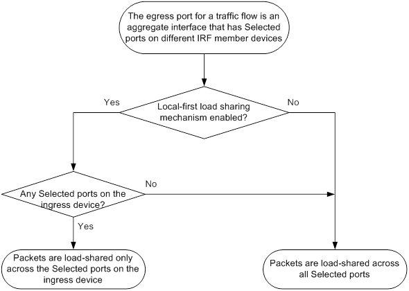
To enable local-first load sharing for link aggregation:
|
Step |
Command |
Remarks |
|
1. Enter system view. |
system-view |
N/A |
|
2. Enable local-first load sharing for link aggregation. |
link-aggregation load-sharing mode local-first |
By default, local-first load sharing for link aggregation is enabled. |
Configuring link aggregation load sharing algorithm settings
To optimize traffic distribution on aggregate links, you can configure a link aggregation load sharing algorithm.
This feature takes effect only when the per-flow load sharing mode is used and the per-flow load sharing mode does not use the following traffic classification criteria:
· Source IP address.
· Destination IP address.
· Source MAC address.
· Destination MAC address.
· Source and destination IP addresses.
· Source and destination MAC addresses.
To configure a link aggregation load sharing algorithm:
|
Step |
Command |
Remarks |
|
1. Enter system view. |
system-view |
N/A |
|
2. Configure a link aggregation load sharing algorithm. |
link-aggregation global load-sharing algorithm algorithm-number |
By default, algorithm 4 is used. If the device fails to load share traffic flows across all Selected ports, you can specify algorithm 1 to 9 in sequence until the problem is solved. |
Enabling link-aggregation traffic redirection
This feature redirects traffic on a Selected port to the remaining available Selected ports of an aggregation group if one of the following events occurs:
· The port is shut down by using the shutdown command.
· The slot that hosts the port reboots, and the aggregation group spans multiple slots.
This feature ensures zero packet loss for known unicast traffic, but does not protect unknown unicast traffic.
You can enable link-aggregation traffic redirection globally or for an aggregation group. Global link-aggregation traffic redirection settings take effect on all aggregation groups. A link aggregation group preferentially uses the group-specific link-aggregation traffic redirection settings. If group-specific link-aggregation traffic redirection is not configured, the group uses the global link-aggregation traffic redirection settings.
Configuration restrictions and guidelines
When you enable link-aggregation traffic redirection, follow these restrictions and guidelines:
· Link-aggregation traffic redirection applies only to dynamic link aggregation groups.
· To prevent traffic interruption, enable link-aggregation traffic redirection on devices at both ends of the aggregate link.
· To prevent packet loss that might occur when a slot reboots, do not enable spanning tree together with link-aggregation traffic redirection.
· Link-aggregation traffic redirection does not operate correctly on an edge aggregate interface.
· As a best practice, enable link-aggregation traffic redirection on aggregate interfaces. If you enable this feature globally, communication with a third-party peer device might be affected if the peer is not compatible with this feature.
Configuration procedure
To enable link-aggregation traffic redirection globally:
|
Step |
Command |
Remarks |
|
1. Enter system view. |
system-view |
N/A |
|
2. Enable link-aggregation traffic redirection globally. |
link-aggregation lacp traffic-redirect-notification enable |
By default, link-aggregation traffic redirection is disabled globally. |
To enable link-aggregation traffic redirection for an aggregation group:
|
Step |
Command |
Remarks |
|
1. Enter system view. |
system-view |
N/A |
|
2. Enter aggregate interface view. |
·
Enter Layer 2 aggregate interface view: ·
Enter Layer 3 aggregate interface view: |
N/A |
|
3. Enable link-aggregation traffic redirection for the aggregation group. |
link-aggregation lacp traffic-redirect-notification enable |
By default, link-aggregation traffic redirection is disabled for an aggregation group. |
Configuring the link aggregation capability for the device
Perform this task to modify the maximum number of aggregation groups and the maximum number of Selected ports per aggregation group.
After you configure the link aggregation capability for the device, save the configuration and reboot the device for the configuration to take effect. Before rebooting the device, make sure you know the possible impact on the network.
For link aggregation to operate correctly, set the same link aggregation capability for both ends of an aggregate link.
The maximum number of Selected ports allowed in an aggregation group is limited by one of the following values, whichever value is smaller:
· Maximum number set by using the link-aggregation selected-port maximum command.
· Maximum number of Selected ports allowed by the link aggregation capability.
To configure the link aggregation capability for the device:
|
Step |
Command |
Remarks |
|
1. Enter system view. |
system-view |
N/A |
|
2. Configure the link aggregation capability for the device. |
link-aggregation capability max-group max-group-number max-selected-port max-selected-port-number |
By default, a device can have a maximum of 1024 aggregation groups and an aggregation group can have a maximum of 16 Selected ports. |
Displaying and maintaining Ethernet link aggregation
Execute display commands in any view and reset commands in user view.
|
Task |
Command |
|
Display information for an aggregate interface or multiple aggregate interfaces. |
display interface [ { bridge-aggregation | route-aggregation } [ interface-number ] ] [ brief [ description | down ] ] |
|
Display the local system ID. |
display lacp system-id |
|
Display the link aggregation capability for the device. |
display link-aggregation capability |
|
Display the global or group-specific link-aggregation load sharing modes. |
display link-aggregation load-sharing mode [ interface [ { bridge-aggregation | route-aggregation } interface-number ] ] |
|
Display forwarding information for the specified traffic flow. |
display link-aggregation load-sharing path interface { bridge-aggregation | route-aggregation } interface-number ingress-port interface-type interface-number [ route ] { { destination-ip ip-address | destination-ipv6 ipv6-address } | { source-ip ip-address | source-ipv6 ipv6-address } | destination-mac mac-address | destination-port port-id | ethernet-type type-number | ip-protocol protocol-id | source-mac mac-address | source-port port-id | vlan vlan-id } * |
|
Display detailed link aggregation information for link aggregation member ports. |
display link-aggregation member-port [ interface-list ] |
|
Display summary information about all aggregation groups. |
display link-aggregation summary |
|
Display detailed information about the specified aggregation groups. |
display link-aggregation verbose [ { bridge-aggregation | route-aggregation } [ interface-number ] ] |
|
Clear LACP statistics for the specified link aggregation member ports. |
reset lacp statistics [ interface interface-list ] |
|
Clear statistics for the specified aggregate interfaces. |
reset counters interface [ { bridge-aggregation | route-aggregation } [ interface-number ] ] |
Ethernet link aggregation configuration examples
Layer 2 static aggregation configuration example
Network requirements
On the network shown in Figure 13, perform the following tasks:
· Configure a Layer 2 static aggregation group on both Device A and Device B.
· Enable VLAN 10 at one end of the aggregate link to communicate with VLAN 10 at the other end.
· Enable VLAN 20 at one end of the aggregate link to communicate with VLAN 20 at the other end.
Configuration procedure
1. Configure Device A:
# Create VLAN 10, and assign port HundredGigE 1/0/4 to VLAN 10.
<DeviceA> system-view
[DeviceA] vlan 10
[DeviceA-vlan10] port hundredgige 1/0/4
[DeviceA-vlan10] quit
# Create VLAN 20, and assign port HundredGigE 1/0/5 to VLAN 20.
[DeviceA] vlan 20
[DeviceA-vlan20] port hundredgige 1/0/5
[DeviceA-vlan20] quit
# Create Layer 2 aggregate interface Bridge-Aggregation 1.
[DeviceA] interface bridge-aggregation 1
[DeviceA-Bridge-Aggregation1] quit
# Assign ports HundredGigE 1/0/1 through HundredGigE 1/0/3 to link aggregation group 1.
[DeviceA] interface hundredgige 1/0/1
[DeviceA-HundredGigE1/0/1] port link-aggregation group 1
[DeviceA-HundredGigE1/0/1] quit
[DeviceA] interface hundredgige 1/0/2
[DeviceA-HundredGigE1/0/2] port link-aggregation group 1
[DeviceA-HundredGigE1/0/2] quit
[DeviceA] interface hundredgige 1/0/3
[DeviceA-HundredGigE1/0/3] port link-aggregation group 1
[DeviceA-HundredGigE1/0/3] quit
# Configure Layer 2 aggregate interface Bridge-Aggregation 1 as a trunk port and assign it to VLANs 10 and 20.
[DeviceA] interface bridge-aggregation 1
[DeviceA-Bridge-Aggregation1] port link-type trunk
[DeviceA-Bridge-Aggregation1] port trunk permit vlan 10 20
[DeviceA-Bridge-Aggregation1] quit
2. Configure Device B in the same way Device A is configured. (Details not shown.)
Verifying the configuration
# Display detailed information about all aggregation groups on Device A.
[DeviceA] display link-aggregation verbose
Loadsharing Type: Shar -- Loadsharing, NonS -- Non-Loadsharing
Port Status: S -- Selected, U -- Unselected, I -- Individual
Port: A -- Auto port, M -- Management port, R -- Reference port
Flags: A -- LACP_Activity, B -- LACP_Timeout, C -- Aggregation,
D -- Synchronization, E -- Collecting, F -- Distributing,
G -- Defaulted, H -- Expired
Aggregate Interface: Bridge-Aggregation1
Aggregation Mode: Static
Loadsharing Type: NonS
Management VLANs: None
Port Status Priority Oper-Key
--------------------------------------------------------------------------------
HGE1/0/1 S 32768 1
HGE1/0/2 S 32768 1
HGE1/0/3 S 32768 1
The output shows that link aggregation group 1 is a Layer 2 static aggregation group that contains three Selected ports.
Layer 2 dynamic aggregation configuration example
Network requirements
On the network shown in Figure 14, perform the following tasks:
· Configure a Layer 2 dynamic aggregation group on both Device A and Device B.
· Enable VLAN 10 at one end of the aggregate link to communicate with VLAN 10 at the other end.
· Enable VLAN 20 at one end of the aggregate link to communicate with VLAN 20 at the other end.
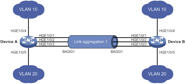
Configuration procedure
1. Configure Device A:
# Create VLAN 10, and assign the port HundredGigE 1/0/4 to VLAN 10.
<DeviceA> system-view
[DeviceA] vlan 10
[DeviceA-vlan10] port hundredgige 1/0/4
[DeviceA-vlan10] quit
# Create VLAN 20, and assign the port HundredGigE 1/0/5 to VLAN 20.
[DeviceA] vlan 20
[DeviceA-vlan20] port hundredgige 1/0/5
[DeviceA-vlan20] quit
# Create Layer 2 aggregate interface Bridge-Aggregation 1, and set the link aggregation mode to dynamic.
[DeviceA] interface bridge-aggregation 1
[DeviceA-Bridge-Aggregation1] link-aggregation mode dynamic
[DeviceA-Bridge-Aggregation1] quit
# Assign ports HundredGigE 1/0/1 through HundredGigE 1/0/3 to link aggregation group 1.
[DeviceA] interface hundredgige 1/0/1
[DeviceA-HundredGigE1/0/1] port link-aggregation group 1
[DeviceA-HundredGigE1/0/1] quit
[DeviceA] interface hundredgige 1/0/2
[DeviceA-HundredGigE1/0/2] port link-aggregation group 1
[DeviceA-HundredGigE1/0/2] quit
[DeviceA] interface hundredgige 1/0/3
[DeviceA-HundredGigE1/0/3] port link-aggregation group 1
[DeviceA-HundredGigE1/0/3] quit
# Configure Layer 2 aggregate interface Bridge-Aggregation 1 as a trunk port and assign it to VLANs 10 and 20.
[DeviceA] interface bridge-aggregation 1
[DeviceA-Bridge-Aggregation1] port link-type trunk
[DeviceA-Bridge-Aggregation1] port trunk permit vlan 10 20
[DeviceA-Bridge-Aggregation1] quit
2. Configure Device B in the same way Device A is configured. (Details not shown.)
Verifying the configuration
# Display detailed information about all aggregation groups on Device A.
[DeviceA] display link-aggregation verbose
Loadsharing Type: Shar -- Loadsharing, NonS -- Non-Loadsharing
Port Status: S -- Selected, U -- Unselected, I -- Individual
Port: A -- Auto port, M -- Management port, R -- Reference port
Flags: A -- LACP_Activity, B -- LACP_Timeout, C -- Aggregation,
D -- Synchronization, E -- Collecting, F -- Distributing,
G -- Defaulted, H -- Expired
Aggregate Interface: Bridge-Aggregation1
Aggregation Mode: Dynamic
Loadsharing Type: NonS
Management VLANs: None
System ID: 0x8000, 000f-e267-6c6a
Local:
Port Status Priority Index Oper-Key Flag
HGE1/0/1 S 32768 11 1 {ACDEF}
HGE1/0/2 S 32768 12 1 {ACDEF}
HGE1/0/3 S 32768 13 1 {ACDEF}
Remote:
Actor Priority Index Oper-Key SystemID Flag
HGE1/0/1 32768 81 1 0x8000, 000f-e267-57ad {ACDEF}
HGE1/0/2 32768 82 1 0x8000, 000f-e267-57ad {ACDEF}
HGE1/0/3 32768 83 1 0x8000, 000f-e267-57ad {ACDEF}
The output shows that link aggregation group 1 is a Layer 2 dynamic aggregation group that contains three Selected ports.
Layer 2 aggregation load sharing configuration example
Network requirements
On the network shown in Figure 15, perform the following tasks:
· Configure Layer 2 static aggregation groups 1 and 2 on Device A and Device B, respectively.
· Enable VLAN 10 at one end of the aggregate link to communicate with VLAN 10 at the other end.
· Enable VLAN 20 at one end of the aggregate link to communicate with VLAN 20 at the other end.
· Configure link aggregation groups 1 and 2 to load share traffic across aggregation group member ports.
? Configure link aggregation group 1 to load share packets based on source MAC addresses.
? Configure link aggregation group 2 to load share packets based on destination MAC addresses.
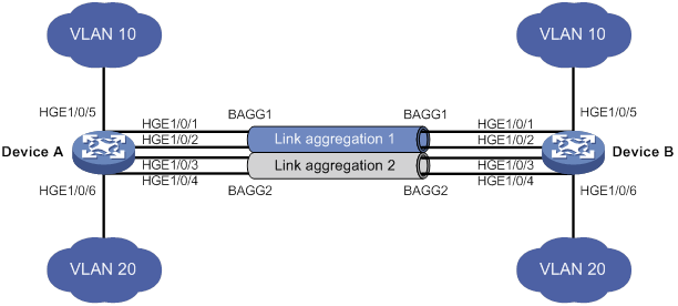
Configuration procedure
1. Configure Device A:
# Create VLAN 10, and assign the port HundredGigE 1/0/5 to VLAN 10.
<DeviceA> system-view
[DeviceA] vlan 10
[DeviceA-vlan10] port hundredgige 1/0/5
[DeviceA-vlan10] quit
# Create VLAN 20, and assign the port HundredGigE 1/0/6 to VLAN 20.
[DeviceA] vlan 20
[DeviceA-vlan20] port hundredgige 1/0/6
[DeviceA-vlan20] quit
# Create Layer 2 aggregate interface Bridge-Aggregation 1.
[DeviceA] interface bridge-aggregation 1
# Configure Layer 2 aggregation group 1 to load share packets based on source MAC addresses.
[DeviceA-Bridge-Aggregation1] link-aggregation load-sharing mode source-mac
[DeviceA-Bridge-Aggregation1] quit
# Assign ports HundredGigE 1/0/1 and HundredGigE 1/0/2 to link aggregation group 1.
[DeviceA] interface hundredgige 1/0/1
[DeviceA-HundredGigE1/0/1] port link-aggregation group 1
[DeviceA-HundredGigE1/0/1] quit
[DeviceA] interface hundredgige 1/0/2
[DeviceA-HundredGigE1/0/2] port link-aggregation group 1
[DeviceA-HundredGigE1/0/2] quit
# Configure Layer 2 aggregate interface Bridge-Aggregation 1 as a trunk port and assign it to VLAN 10.
[DeviceA] interface bridge-aggregation 1
[DeviceA-Bridge-Aggregation1] port link-type trunk
[DeviceA-Bridge-Aggregation1] port trunk permit vlan 10
[DeviceA-Bridge-Aggregation1] quit
# Create Layer 2 aggregate interface Bridge-Aggregation 2.
[DeviceA] interface bridge-aggregation 2
# Configure Layer 2 aggregation group 2 to load share packets based on destination MAC addresses.
[DeviceA-Bridge-Aggregation2] link-aggregation load-sharing mode destination-mac
[DeviceA-Bridge-Aggregation2] quit
# Assign ports HundredGigE 1/0/3 and HundredGigE 1/0/4 to link aggregation group 2.
[DeviceA] interface hundredgige 1/0/3
[DeviceA-HundredGigE1/0/3] port link-aggregation group 2
[DeviceA-HundredGigE1/0/3] quit
[DeviceA] interface hundredgige 1/0/4
[DeviceA-HundredGigE1/0/4] port link-aggregation group 2
[DeviceA-HundredGigE1/0/4] quit
# Configure Layer 2 aggregate interface Bridge-Aggregation 2 as a trunk port and assign it to VLAN 20.
[DeviceA] interface bridge-aggregation 2
[DeviceA-Bridge-Aggregation2] port link-type trunk
[DeviceA-Bridge-Aggregation2] port trunk permit vlan 20
[DeviceA-Bridge-Aggregation2] quit
2. Configure Device B in the same way Device A is configured. (Details not shown.)
Verifying the configuration
# Display detailed information about all aggregation groups on Device A.
[DeviceA] display link-aggregation verbose
Loadsharing Type: Shar -- Loadsharing, NonS -- Non-Loadsharing
Port Status: S -- Selected, U -- Unselected, I -- Individual
Port: A -- Auto port, M -- Management port, R -- Reference port
Flags: A -- LACP_Activity, B -- LACP_Timeout, C -- Aggregation,
D -- Synchronization, E -- Collecting, F -- Distributing,
G -- Defaulted, H -- Expired
Aggregate Interface: Bridge-Aggregation1
Aggregation Mode: Static
Loadsharing Type: Shar
Management VLANs: None
Port Status Priority Oper-Key
--------------------------------------------------------------------------------
HGE1/0/1 S 32768 1
HGE1/0/2 S 32768 1
Aggregate Interface: Bridge-Aggregation2
Aggregation Mode: Static
Loadsharing Type: Shar
Management VLANs: None
Port Status Priority Oper-Key
--------------------------------------------------------------------------------
HGE1/0/3 S 32768 2
HGE1/0/4 S 32768 2
The output shows that:
· Link aggregation groups 1 and 2 are both load-shared Layer 2 static aggregation groups.
· Each aggregation group contains two Selected ports.
# Display all the group-specific load sharing modes on Device A.
[DeviceA] display link-aggregation load-sharing mode interface
Bridge-Aggregation1 Load-Sharing Mode:
source-mac address
Bridge-Aggregation2 Load-Sharing Mode:
destination-mac address
The output shows that:
· Link aggregation group 1 load shares packets based on source MAC addresses.
· Link aggregation group 2 load shares packets based on destination MAC addresses.
Layer 2 edge aggregate interface configuration example
Network requirements
As shown in Figure 16, a Layer 2 dynamic aggregation group is configured on the device. The server is not configured with dynamic link aggregation.
Configure an edge aggregate interface so that both HundredGigE 1/0/1 and HundredGigE 1/0/2 can forward traffic to improve link reliability.
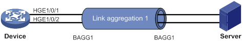
Configuration procedure
# Create Layer 2 aggregate interface Bridge-Aggregation 1, and set the link aggregation mode to dynamic.
<Device> system-view
[Device] interface bridge-aggregation 1
[Device-Bridge-Aggregation1] link-aggregation mode dynamic
# Configure Layer 2 aggregate interface Bridge-Aggregation 1 as an edge aggregate interface.
[Device-Bridge-Aggregation1] lacp edge-port
[Device-Bridge-Aggregation1] quit
# Assign ports HundredGigE 1/0/1 and HundredGigE 1/0/2 to link aggregation group 1.
[Device] interface hundredgige 1/0/1
[Device-HundredGigE1/0/1] port link-aggregation group 1
[Device-HundredGigE1/0/1] quit
[Device] interface hundredgige 1/0/2
[Device-HundredGigE1/0/2] port link-aggregation group 1
[Device-HundredGigE1/0/2] quit
Verifying the configuration
# Display detailed information about all aggregation groups on the device when the server is not configured with dynamic link aggregation.
[Device] display link-aggregation verbose
Loadsharing Type: Shar -- Loadsharing, NonS -- Non-Loadsharing
Port Status: S -- Selected, U -- Unselected, I -- Individual
Port: A -- Auto port, M -- Management port, R -- Reference port
Flags: A -- LACP_Activity, B -- LACP_Timeout, C -- Aggregation,
D -- Synchronization, E -- Collecting, F -- Distributing,
G -- Defaulted, H -- Expired
Aggregate Interface: Bridge-Aggregation1
Aggregation Mode: Dynamic
Loadsharing Type: NonS
Management VLANs: None
System ID: 0x8000, 000f-e267-6c6a
Local:
Port Status Priority Index Oper-Key Flag
HGE1/0/1 I 32768 11 1 {AG}
HGE1/0/2 I 32768 12 1 {AG}
Remote:
Actor Priority Index Oper-Key SystemID Flag
HGE1/0/1 32768 81 0 0x8000, 0000-0000-0000 {DEF}
HGE1/0/2 32768 82 0 0x8000, 0000-0000-0000 {DEF}
The output shows that HundredGigE 1/0/1 and HundredGigE 1/0/2 are in Individual state when they do not receive LACPDUs from the server. Both HundredGigE 1/0/1 and HundredGigE 1/0/2 can forward traffic. When one port fails, its traffic is automatically switched to the other port.
Layer 3 static aggregation configuration example
Network requirements
On the network shown in Figure 17, perform the following tasks:
· Configure a Layer 3 static aggregation group on both Device A and Device B.
· Configure IP addresses and subnet masks for the corresponding Layer 3 aggregate interfaces.
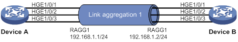
Configuration procedure
1. Configure Device A:
# Create Layer 3 aggregate interface Route-Aggregation 1, and configure an IP address and subnet mask for the aggregate interface.
<DeviceA> system-view
[DeviceA] interface route-aggregation 1
[DeviceA-Route-Aggregation1] ip address 192.168.1.1 24
[DeviceA-Route-Aggregation1] quit
# Assign Layer 3 Ethernet interfaces HundredGigE 1/0/1 through HundredGigE 1/0/3 to aggregation group 1.
[DeviceA] interface hundredgige 1/0/1
[DeviceA-HundredGigE1/0/1] port link-aggregation group 1
[DeviceA-HundredGigE1/0/1] quit
[DeviceA] interface hundredgige 1/0/2
[DeviceA-HundredGigE1/0/2] port link-aggregation group 1
[DeviceA-HundredGigE1/0/2] quit
[DeviceA] interface hundredgige 1/0/3
[DeviceA-HundredGigE1/0/3] port link-aggregation group 1
[DeviceA-HundredGigE1/0/3] quit
2. Configure Device B in the same way Device A is configured. (Details not shown.)
Verifying the configuration
# Display detailed information about all aggregation groups on Device A.
[DeviceA] display link-aggregation verbose
Loadsharing Type: Shar -- Loadsharing, NonS -- Non-Loadsharing
Port Status: S -- Selected, U -- Unselected, I -- Individual
Port: A -- Auto port, M -- Management port, R -- Reference port
Flags: A -- LACP_Activity, B -- LACP_Timeout, C -- Aggregation,
D -- Synchronization, E -- Collecting, F -- Distributing,
G -- Defaulted, H -- Expired
Aggregate Interface: Route-Aggregation1
Aggregation Mode: Static
Loadsharing Type: NonS
Management VLANs: None
Port Status Priority Oper-Key
--------------------------------------------------------------------------------
HGE1/0/1 S 32768 1
HGE1/0/2 S 32768 1
HGE1/0/3 S 32768 1
The output shows that link aggregation group 1 is a Layer 3 static aggregation group that contains three Selected ports.
Layer 3 dynamic aggregation configuration example
Network requirements
On the network shown in Figure 18, perform the following tasks:
· Configure a Layer 3 dynamic aggregation group on both Device A and Device B.
· Configure IP addresses and subnet masks for the corresponding Layer 3 aggregate interfaces.
Configuration procedure
1. Configure Device A:
# Create Layer 3 aggregate interface Route-Aggregation 1.
<DeviceA> system-view
[DeviceA] interface route-aggregation 1
# Set the link aggregation mode to dynamic.
[DeviceA-Route-Aggregation1] link-aggregation mode dynamic
# Configure an IP address and subnet mask for Route-Aggregation 1.
[DeviceA-Route-Aggregation1] ip address 192.168.1.1 24
[DeviceA-Route-Aggregation1] quit
# Assign Layer 3 Ethernet interfaces HundredGigE 1/0/1 through HundredGigE 1/0/3 to aggregation group 1.
[DeviceA] interface hundredgige 1/0/1
[DeviceA-HundredGigE1/0/1] port link-aggregation group 1
[DeviceA-HundredGigE1/0/1] quit
[DeviceA] interface hundredgige 1/0/2
[DeviceA-HundredGigE1/0/2] port link-aggregation group 1
[DeviceA-HundredGigE1/0/2] quit
[DeviceA] interface hundredgige 1/0/3
[DeviceA-HundredGigE1/0/3] port link-aggregation group 1
[DeviceA-HundredGigE1/0/3] quit
2. Configure Device B in the same way Device A is configured. (Details not shown.)
Verifying the configuration
# Display detailed information about all aggregation groups on Device A.
[DeviceA] display link-aggregation verbose
Loadsharing Type: Shar -- Loadsharing, NonS -- Non-Loadsharing
Port Status: S -- Selected, U -- Unselected, I -- Individual
Port: A -- Auto port, M -- Management port, R -- Reference port
Flags: A -- LACP_Activity, B -- LACP_Timeout, C -- Aggregation,
D -- Synchronization, E -- Collecting, F -- Distributing,
G -- Defaulted, H -- Expired
Aggregate Interface: Route-Aggregation1
Aggregation Mode: Dynamic
Loadsharing Type: NonS
Management VLANs: None
System ID: 0x8000, 000f-e267-6c6a
Local:
Port Status Priority Index Oper-Key Flag
HGE1/0/1 S 32768 11 1 {ACDEF}
HGE1/0/2 S 32768 12 1 {ACDEF}
HGE1/0/3 S 32768 13 1 {ACDEF}
Remote:
Actor Priority Index Oper-Key SystemID Flag
HGE1/0/1 32768 81 1 0x8000, 000f-e267-57ad {ACDEF}
HGE1/0/2 32768 82 1 0x8000, 000f-e267-57ad {ACDEF}
HGE1/0/3 32768 83 1 0x8000, 000f-e267-57ad {ACDEF}
The output shows that link aggregation group 1 is a Layer 3 dynamic aggregation group that contains three Selected ports.
Layer 3 aggregation load sharing configuration example
Network requirements
On the network shown in Figure 19, perform the following tasks:
· Configure Layer 3 static aggregation groups 1 and 2 on Device A and Device B, respectively.
· Configure IP addresses and subnet masks for the corresponding Layer 3 aggregate interfaces.
· Configure link aggregation group 1 to load share packets based on source IP addresses.
· Configure link aggregation group 2 to load share packets based on destination IP addresses.
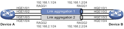
Configuration procedure
1. Configure Device A:
# Create Layer 3 aggregate interface Route-Aggregation 1.
<DeviceA> system-view
[DeviceA] interface route-aggregation 1
# Configure Layer 3 aggregation group 1 to load share packets based on source IP addresses.
[DeviceA-Route-Aggregation1] link-aggregation load-sharing mode source-ip
# Configure an IP address and subnet mask for Layer 3 aggregate interface Route-Aggregation 1.
[DeviceA-Route-Aggregation1] ip address 192.168.1.1 24
[DeviceA-Route-Aggregation1] quit
# Assign Layer 3 Ethernet interfaces HundredGigE 1/0/1 and HundredGigE 1/0/2 to aggregation group 1.
[DeviceA] interface hundredgige 1/0/1
[DeviceA-HundredGigE1/0/1] port link-aggregation group 1
[DeviceA-HundredGigE1/0/1] quit
[DeviceA] interface hundredgige 1/0/2
[DeviceA-HundredGigE1/0/2] port link-aggregation group 1
[DeviceA-HundredGigE1/0/2] quit
# Create Layer 3 aggregate interface Route-Aggregation 2.
[DeviceA] interface route-aggregation 2
# Configure Layer 3 aggregation group 2 to load share packets based on destination IP addresses.
[DeviceA-Route-Aggregation2] link-aggregation load-sharing mode destination-ip
# Configure an IP address and subnet mask for Layer 3 aggregate interface Route-Aggregation 2.
[DeviceA-Route-Aggregation2] ip address 192.168.2.1 24
[DeviceA-Route-Aggregation2] quit
# Assign Layer 3 Ethernet interfaces HundredGigE 1/0/3 and HundredGigE 1/0/4 to aggregation group 2.
[DeviceA] interface hundredgige 1/0/3
[DeviceA-HundredGigE1/0/3] port link-aggregation group 2
[DeviceA-HundredGigE1/0/3] quit
[DeviceA] interface hundredgige 1/0/4
[DeviceA-HundredGigE1/0/4] port link-aggregation group 2
[DeviceA-HundredGigE1/0/4] quit
2. Configure Device B in the same way Device A is configured. (Details not shown.)
Verifying the configuration
# Display detailed information about all aggregation groups on Device A.
[DeviceA] display link-aggregation verbose
Loadsharing Type: Shar -- Loadsharing, NonS -- Non-Loadsharing
Port Status: S -- Selected, U -- Unselected, I -- Individual
Port: A -- Auto port, M -- Management port, R -- Reference port
Flags: A -- LACP_Activity, B -- LACP_Timeout, C -- Aggregation,
D -- Synchronization, E -- Collecting, F -- Distributing,
G -- Defaulted, H -- Expired
Aggregate Interface: Route-Aggregation1
Aggregation Mode: Static
Loadsharing Type: Shar
Management VLANs: None
Port Status Priority Oper-Key
--------------------------------------------------------------------------------
HGE1/0/1 S 32768 1
HGE1/0/2 S 32768 1
Aggregate Interface: Route-Aggregation2
Aggregation Mode: Static
Loadsharing Type: Shar
Management VLANs: None
Port Status Priority Oper-Key
--------------------------------------------------------------------------------
HGE1/0/3 S 32768 2
HGE1/0/4 S 32768 2
The output shows that:
· Link aggregation groups 1 and 2 are both load-shared Layer 3 static aggregation groups.
· Each aggregation group contains two Selected ports.
# Display all the group-specific load sharing modes on Device A.
[DeviceA] display link-aggregation load-sharing mode interface
Route-Aggregation1 Load-Sharing Mode:
source-ip address
Route-Aggregation2 Load-Sharing Mode:
destination-ip address
The output shows that:
· Link aggregation group 1 load shares packets based on source IP addresses.
· Link aggregation group 2 load shares packets based on destination IP addresses.
Layer 3 edge aggregate interface configuration example
Network requirements
As shown in Figure 20, a Layer 3 dynamic aggregation group is configured on the device. The server is not configured with dynamic link aggregation.
Configure an edge aggregate interface so that both HundredGigE 1/0/1 and HundredGigE 1/0/2 can forward traffic to improve link reliability.
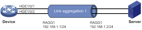
Configuration procedure
# Create Layer 3 aggregate interface Route-Aggregation 1, and set the link aggregation mode to dynamic.
<Device> system-view
[Device] interface route-aggregation 1
[Device-Route-Aggregation1] link-aggregation mode dynamic
# Configure an IP address and subnet mask for Layer 3 aggregate interface Route-Aggregation 1.
[Device-Route-Aggregation1] ip address 192.168.1.1 24
# Configure Layer 3 aggregate interface Route-Aggregation 1 as an edge aggregate interface.
[Device-Route-Aggregation1] lacp edge-port
[Device-Route-Aggregation1] quit
# Assign Layer 3 Ethernet interfaces HundredGigE 1/0/1 and HundredGigE 1/0/2 to aggregation group 1.
[Device] interface hundredgige 1/0/1
[Device-HundredGigE1/0/1] port link-aggregation group 1
[Device-HundredGigE1/0/1] quit
[Device] interface hundredgige 1/0/2
[Device-HundredGigE1/0/2] port link-aggregation group 1
[Device-HundredGigE1/0/2] quit
Verifying the configuration
# Display detailed information about all aggregation groups on the device when the server is not configured with dynamic link aggregation.
[Device] display link-aggregation verbose
Loadsharing Type: Shar -- Loadsharing, NonS -- Non-Loadsharing
Port Status: S -- Selected, U -- Unselected, I -- Individual
Port: A -- Auto port, M -- Management port, R -- Reference port
Flags: A -- LACP_Activity, B -- LACP_Timeout, C -- Aggregation,
D -- Synchronization, E -- Collecting, F -- Distributing,
G -- Defaulted, H -- Expired
Aggregate Interface: Route-Aggregation1
Aggregation Mode: Dynamic
Loadsharing Type: NonS
Management VLANs: None
System ID: 0x8000, 000f-e267-6c6a
Local:
Port Status Priority Index Oper-Key Flag
HGE1/0/1 I 32768 11 1 {AG}
HGE1/0/2 I 32768 12 1 {AG}
Remote:
Actor Priority Index Oper-Key SystemID Flag
HGE1/0/1 32768 81 0 0x8000, 0000-0000-0000 {DEF}
HGE1/0/2 32768 82 0 0x8000, 0000-0000-0000 {DEF}
The output shows that HundredGigE 1/0/1 and HundredGigE 1/0/2 are in Individual state when they do not receive LACPDUs from the server. Both HundredGigE 1/0/1 and HundredGigE 1/0/2 can forward traffic. When one port fails, its traffic is automatically switched to the other port.
Configuring port isolation
The port isolation feature isolates Layer 2 traffic for data privacy and security without using VLANs.
Ports in an isolation group cannot communicate with each other. However, they can communicate with ports outside the isolation group.
Assigning a port to an isolation group
The device supports multiple isolation groups, which can be configured manually. The number of ports assigned to an isolation group is not limited.
To assign a port to an isolation group:
|
Step |
Command |
Remarks |
|
1. Enter system view. |
system-view |
N/A |
|
2. Create an isolation group. |
port-isolate group group-id |
By default, no isolation groups exist. |
|
3. Enter interface view. |
·
Enter Layer 2 Ethernet interface view: ·
Enter Layer 2 aggregate interface view: |
· The configuration in Layer 2 Ethernet interface view applies only to the interface. · The configuration in Layer 2 aggregate interface view applies to the Layer 2 aggregate interface and its aggregation member ports. If the device fails to apply the configuration to the aggregate interface, it does not assign any aggregation member port to the isolation group. If the failure occurs on an aggregation member port, the device skips the port and continues to assign other aggregation member ports to the isolation group. |
|
4. Assign the port to the isolation group. |
port-isolate enable group group-id |
By default, the port is not in any isolation group. You can assign a port to only one isolation group. If you execute the port-isolate enable group command multiple times, the most recent configuration takes effect. |
Displaying and maintaining port isolation
Execute display commands in any view.
|
Task |
Command |
|
Display isolation group information. |
display port-isolate group [ group-id ] |
Port isolation configuration example
Network requirements
As shown in Figure 21:
· LAN users Host A, Host B, and Host C are connected to HundredGigE 1/0/1, HundredGigE 1/0/2, and HundredGigE 1/0/3 on the device, respectively.
· The device connects to the Internet through HundredGigE 1/0/4.
Configure the device to provide Internet access for the hosts, and isolate them from one another at Layer 2.
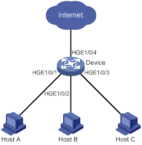
Configuration procedure
# Create isolation group 1.
<Device> system-view
[Device] port-isolate group 1
# Assign HundredGigE 1/0/1, HundredGigE 1/0/2, and HundredGigE 1/0/3 to isolation group 1.
[Device] interface hundredgige 1/0/1
[Device-HundredGigE1/0/1] port-isolate enable group 1
[Device-HundredGigE1/0/1] quit
[Device] interface hundredgige 1/0/2
[Device-HundredGigE1/0/2] port-isolate enable group 1
[Device-HundredGigE1/0/2] quit
[Device] interface hundredgige 1/0/3
[Device-HundredGigE1/0/3] port-isolate enable group 1
[Device-HundredGigE1/0/3] quit
Verifying the configuration
# Display information about isolation group 1.
[Device] display port-isolate group 1
Port isolation group information:
Group ID: 1
Group members:
HundredGigE1/0/1
HundredGigE1/0/2
HundredGigE1/0/3
The output shows that HundredGigE 1/0/1, HundredGigE 1/0/2, and HundredGigE 1/0/3 are assigned to isolation group 1. As a result, Host A, Host B, and Host C are isolated from one another at layer 2.
Configuring spanning tree protocols
Spanning tree protocols eliminate loops in a physical link-redundant network by selectively blocking redundant links and putting them in a standby state.
The recent versions of STP include the Rapid Spanning Tree Protocol (RSTP), the Per-VLAN Spanning Tree (PVST), and the Multiple Spanning Tree Protocol (MSTP).
STP
STP was developed based on the 802.1d standard of IEEE to eliminate loops at the data link layer in a LAN. Networks often have redundant links as backups in case of failures, but loops are a very serious problem. Devices running STP detect loops in the network by exchanging information with one another. They eliminate loops by selectively blocking certain ports to prune the loop structure into a loop-free tree structure. This avoids proliferation and infinite cycling of packets that would occur in a loop network.
In a narrow sense, STP refers to IEEE 802.1d STP. In a broad sense, STP refers to the IEEE 802.1d STP and various enhanced spanning tree protocols derived from that protocol.
STP protocol frames
STP uses bridge protocol data units (BPDUs), also known as configuration messages, as its protocol frames. This chapter uses BPDUs to represent all types of spanning tree protocol frames.
STP-enabled devices exchange BPDUs to establish a spanning tree. BPDUs contain sufficient information for the devices to complete spanning tree calculation.
STP uses two types of BPDUs, configuration BPDUs and topology change notification (TCN) BPDUs.
Configuration BPDUs
Devices exchange configuration BPDUs to elect the root bridge and determine port roles. Figure 22 shows the configuration BPDU format.
Figure 22 Configuration BPDU format
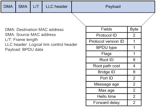
The payload of a configuration BPDU includes the following fields:
· Protocol ID—Fixed at 0x0000, which represents IEEE 802.1d.
· Protocol version ID—Spanning tree protocol version ID. The protocol version ID for STP is 0x00.
· BPDU type—Type of the BPDU. The value is 0x00 for a configuration BPDU.
· Flags—An 8-bit field indicates the purpose of the BPDU. The lowest bit is the Topology Change (TC) flag. The highest bit is the Topology Change Acknowledge (TCA) flag. All other bits are reserved.
· Root ID—Root bridge ID formed by the priority and MAC address of the root bridge.
· Root path cost—Cost of the path to the root bridge.
· Bridge ID—Designated bridge ID formed by the priority and MAC address of the designated bridge.
· Port ID—Designated port ID formed by the priority and global port number of the designated port.
· Message age—Age of the configuration BPDU while it propagates in the network.
· Max age—Maximum age of the configuration BPDU stored on the switch.
· Hello time—Configuration BPDU transmission interval.
· Forward delay—Delay for STP bridges to transit port state.
Devices use the root bridge ID, root path cost, designated bridge ID, designated port ID, message age, max age, hello time, and forward delay for spanning tree calculation.
TCN BPDUs
Devices use TCN BPDUs to announce changes in the network topology. Figure 23 shows the TCN BPDU format.
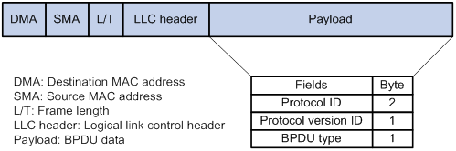
The payload of a TCN BPDU includes the following fields:
· Protocol ID—Fixed at 0x0000, which represents IEEE 802.1d.
· Protocol version ID—Spanning tree protocol version ID. The protocol version ID for STP is 0x00.
· BPDU type—Type of the BPDU. The value is 0x80 for a TCN BPDU.
A non-root bridge sends TCN BPDUs when one of the following events occurs on the bridge:
· A port transits to the forwarding state, and the bridge has a minimum of one designated port.
· A port transits from the forwarding or learning state to the blocking state.
The non-root bridge uses TCN BPDUs to notify the root bridge once the network topology changes. The root bridge then sets the TC flag in its configuration BPDU and propagates it to other bridges.
Basic concepts in STP
Root bridge
A tree network must have a root bridge. The entire network contains only one root bridge, and all the other bridges in the network are called leaf nodes. The root bridge is not permanent, but can change with changes of the network topology.
Upon initialization of a network, each device generates and periodically sends configuration BPDUs, with itself as the root bridge. After network convergence, only the root bridge generates and periodically sends configuration BPDUs. The other devices only forward the BPDUs.
Root port
Designated bridge and designated port
|
Classification |
Designated bridge |
Designated port |
|
For a device |
Device directly connected to the local device and responsible for forwarding BPDUs to the local device. |
Port through which the designated bridge forwards BPDUs to this device. |
|
For a LAN |
Device responsible for forwarding BPDUs to this LAN segment. |
Port through which the designated bridge forwards BPDUs to this LAN segment. |
As shown in Figure 24, Device B and Device C are directly connected to a LAN.
If Device A forwards BPDUs to Device B through port A1, the designated bridge and designated port are as follows:
· The designated bridge for Device B is Device A.
· The designated port for Device B is port A1 on Device A.
If Device B forwards BPDUs to the LAN, the designated bridge and designated port are as follows:
· The designated bridge for the LAN is Device B.
· The designated port for the LAN is port B2 on Device B.
Figure 24 Designated bridges and designated ports
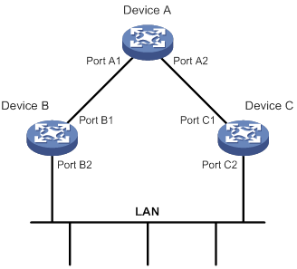
Port states
Table 5 lists the port states in STP.
|
State |
Receives/sends BPDUs |
Learns MAC addresses |
Forwards use data |
|
Disabled |
No |
No |
No |
|
Listening |
Yes |
No |
No |
|
Learning |
Yes |
Yes |
No |
|
Forwarding |
Yes |
Yes |
Yes |
|
Blocking |
Receive |
No |
No |
Path cost
Path cost is a reference value used for link selection in STP. To prune the network into a loop-free tree, STP calculates path costs to select the most robust links and block redundant links that are less robust.
Calculation process of the STP algorithm
The spanning tree calculation process described in the following sections is an example of a simplified process.
Calculation process
The STP algorithm uses the following calculation process:
1. Network initialization.
Upon initialization of a device, each port generates a BPDU with the following contents:
? The port as the designated port.
? The device as the root bridge.
? 0 as the root path cost.
? The device ID as the designated bridge ID.
2. Root bridge selection.
Initially, each STP-enabled device on the network assumes itself to be the root bridge, with its own device ID as the root bridge ID. By exchanging configuration BPDUs, the devices compare their root bridge IDs to elect the device with the smallest root bridge ID as the root bridge.
3. Root port and designated ports selection on the non-root bridges.
|
Step |
Description |
|
1 |
A non-root-bridge device regards the port on which it received the optimum configuration BPDU as the root port. Table 6 describes how the optimum configuration BPDU is selected. |
|
2 |
Based on the configuration BPDU and the path cost of the root port, the device calculates a designated port configuration BPDU for each of the other ports. · The root bridge ID is replaced with that of the configuration BPDU of the root port. · The root path cost is replaced with that of the configuration BPDU of the root port plus the path cost of the root port. · The designated bridge ID is replaced with the ID of this device. · The designated port ID is replaced with the ID of this port. |
|
3 |
The device compares the calculated configuration BPDU with the configuration BPDU on the port whose port role will be determined. Then, the device acts depending on the result of the comparison: · If the calculated configuration BPDU is superior, the device performs the following operations: ? Considers this port as the designated port. ? Replaces the configuration BPDU on the port with the calculated configuration BPDU. ? Periodically sends the calculated configuration BPDU. · If the configuration BPDU on the port is superior, the device blocks this port without updating its configuration BPDU. The blocked port can receive BPDUs, but cannot send BPDUs or forward data traffic. |
When the network topology is stable, only the root port and designated ports forward user traffic. Other ports are all in the blocking state to receive BPDUs but not to forward BPDUs or user traffic.
Table 6 Selecting the optimum configuration BPDU
|
Step |
Actions |
|
1 |
Upon receiving a configuration BPDU on a port, the device compares the priority of the received configuration BPDU with that of the configuration BPDU generated by the port. · If the former priority is lower, the device discards the received configuration BPDU and keeps the configuration BPDU the port generated. · If the former priority is higher, the device replaces the content of the configuration BPDU generated by the port with the content of the received configuration BPDU. |
|
2 |
The device compares the configuration BPDUs of all the ports and chooses the optimum configuration BPDU. |
The following are the principles of configuration BPDU comparison:
a. The configuration BPDU with the lowest root bridge ID has the highest priority.
b. If configuration BPDUs have the same root bridge ID, their root path costs are compared. For example, the root path cost in a configuration BPDU plus the path cost of a receiving port is S. The configuration BPDU with the smallest S value has the highest priority.
c. If all configuration BPDUs have the same root bridge ID and S value, the following attributes are compared in sequence:
- Designated bridge IDs.
- Designated port IDs.
- IDs of the receiving ports.
The configuration BPDU that contains a smaller designated bridge ID, designated port ID, or receiving port ID is selected.
A tree-shape topology forms when the root bridge, root ports, and designated ports are selected.
Example of STP calculation
Figure 25 provides an example showing how the STP algorithm works.
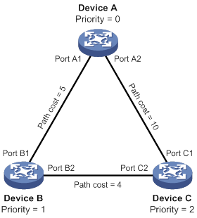
As shown in Figure 25, the priority values of Device A, Device B, and Device C are 0, 1, and 2, respectively. The path costs of links among the three devices are 5, 10, and 4.
1. Device state initialization.
In Table 7, each configuration BPDU contains the following fields: root bridge ID, root path cost, designated bridge ID, and designated port ID.
Table 7 Initial state of each device
|
Device |
Port name |
Configuration BPDU on the port |
|
Device A |
Port A1 |
{0, 0, 0, Port A1} |
|
Port A2 |
{0, 0, 0, Port A2} |
|
|
Device B |
Port B1 |
{1, 0, 1, Port B1} |
|
Port B2 |
{1, 0, 1, Port B2} |
|
|
Device C |
Port C1 |
{2, 0, 2, Port C1} |
|
Port C2 |
{2, 0, 2, Port C2} |
2. Configuration BPDUs comparison on each device.
In Table 8, each configuration BPDU contains the following fields: root bridge ID, root path cost, designated bridge ID, and designated port ID.
Table 8 Comparison process and result on each device
|
Device |
Comparison process |
Configuration BPDU on ports after comparison |
|
Device A |
Port A1 performs the following operations: 1. Receives the configuration BPDU of Port B1 {1, 0, 1, Port B1}. 2. Determines that its existing configuration BPDU {0, 0, 0, Port A1} is superior to the received configuration BPDU. 3. Discards the received one. Port A2 performs the following operations: 1. Receives the configuration BPDU of Port C1 {2, 0, 2, Port C1}. 2. Determines that its existing configuration BPDU {0, 0, 0, Port A2} is superior to the received configuration BPDU. 3. Discards the received one. Device A determines that it is both the root bridge and designated bridge in the configuration BPDUs of all its ports. It considers itself as the root bridge. It does not change the configuration BPDU of any port and starts to periodically send configuration BPDUs. |
· Port A1: {0, 0, 0, Port A1} · Port A2: {0, 0, 0, Port A2} |
|
Device B |
Port B1 performs the following operations: 1. Receives the configuration BPDU of Port A1 {0, 0, 0, Port A1}. 2. Determines that the received configuration BPDU is superior to its existing configuration BPDU {1, 0, 1, Port B1}. 3. Updates its configuration BPDU. Port B2 performs the following operations: 1. Receives the configuration BPDU of Port C2 {2, 0, 2, Port C2}. 2. Determines that its existing configuration BPDU {1, 0, 1, Port B2} is superior to the received configuration BPDU. 3. Discards the received BPDU. |
· Port B1: {0, 0, 0, Port A1} · Port B2: {1, 0, 1, Port B2} |
|
Device B performs the following operations: 1. Compares the configuration BPDUs of all its ports. 2. Decides that the configuration BPDU of Port B1 is the optimum. 3. Selects Port B1 as the root port with the configuration BPDU unchanged. Based on the configuration BPDU and path cost of the root port, Device B calculates a designated port configuration BPDU for Port B2 {0, 5, 1, Port B2}. Device B compares it with the existing configuration BPDU of Port B2 {1, 0, 1, Port B2}. Device B determines that the calculated one is superior, and determines that Port B2 is the designated port. It replaces the configuration BPDU on Port B2 with the calculated one, and periodically sends the calculated configuration BPDU. |
· Root port (Port B1): {0, 0, 0, Port A1} · Designated port (Port B2): {0, 5, 1, Port B2} |
|
|
Device C |
Port C1 performs the following operations: 1. Receives the configuration BPDU of Port A2 {0, 0, 0, Port A2}. 2. Determines that the received configuration BPDU is superior to its existing configuration BPDU {2, 0, 2, Port C1}. 3. Updates its configuration BPDU. Port C2 performs the following operations: 1. Receives the original configuration BPDU of Port B2 {1, 0, 1, Port B2}. 2. Determines that the received configuration BPDU is superior to the existing configuration BPDU {2, 0, 2, Port C2}. 3. Updates its configuration BPDU. |
· Port C1: {0, 0, 0, Port A2} · Port C2: {1, 0, 1, Port B2} |
|
Device C performs the following operations: 1. Compares the configuration BPDUs of all its ports. 2. Decides that the configuration BPDU of Port C1 is the optimum. 3. Selects Port C1 as the root port with the configuration BPDU unchanged. Based on the configuration BPDU and path cost of the root port, Device C calculates the configuration BPDU of Port C2 {0, 10, 2, Port C2}. Device C compares it with the existing configuration BPDU of Port C2 {1, 0, 1, Port B2}. Device C determines that the calculated configuration BPDU is superior to the existing one, selects Port C2 as the designated port, and replaces the configuration BPDU of Port C2 with the calculated one. |
· Root port (Port C1): {0, 0, 0, Port A2} · Designated port (Port C2): {0, 10, 2, Port C2} |
|
|
Port C2 performs the following operations: 1. Receives the updated configuration BPDU of Port B2 {0, 5, 1, Port B2}. 2. Determines that the received configuration BPDU is superior to its existing configuration BPDU {0, 10, 2, Port C2}. 3. Updates its configuration BPDU. Port C1 performs the following operations: 1. Receives a periodic configuration BPDU {0, 0, 0, Port A2} from Port A2. 2. Determines that it is the same as the existing configuration BPDU. 3. Discards the received BPDU. |
· Port C1: {0, 0, 0, Port A2} · Port C2: {0, 5, 1, Port B2} |
|
|
Device C determines that the root path cost of Port C1 is larger than that of Port C2. The root path cost of Port C1 is 10, root path cost of the received configuration BPDU (0) plus path cost of Port C1 (10). The root path cost of Port C2 is 9, root path cost of the received configuration BPDU (5) plus path cost of Port C2 (4). Device C determines that the configuration BPDU of Port C2 is the optimum, and selects Port C2 as the root port with the configuration BPDU unchanged. Based on the configuration BPDU and path cost of the root port, Device C performs the following operations: 1. Calculates a designated port configuration BPDU for Port C1 {0, 9, 2, Port C1}. 2. Compares it with the existing configuration BPDU of Port C1 {0, 0, 0, Port A2}. 3. Determines that the existing configuration BPDU is superior to the calculated one and blocks Port C1 with the configuration BPDU unchanged. Port C1 does not forward data until a new event triggers a spanning tree calculation process: for example, the link between Device B and Device C is down. |
· Blocked port (Port C1): {0, 0, 0, Port A2} · Root port (Port C2): {0, 5, 1, Port B2} |
After the comparison processes described in Table 8, a spanning tree with Device A as the root bridge is established, as shown in Figure 26.
Figure 26 The final calculated spanning tree
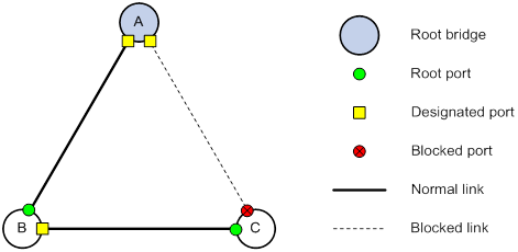
The configuration BPDU forwarding mechanism of STP
The configuration BPDUs of STP are forwarded according to these guidelines:
· Upon network initiation, every device regards itself as the root bridge and generates configuration BPDUs with itself as the root. Then it sends the configuration BPDUs at a regular hello interval.
· If the root port receives a configuration BPDU superior to the configuration BPDU of the port, the device performs the following operations:
? Increases the message age carried in the configuration BPDU.
? Starts a timer to time the configuration BPDU.
? Sends this configuration BPDU through the designated port.
· If a designated port receives a configuration BPDU with a lower priority than its configuration BPDU, the port immediately responds with its configuration BPDU.
· If a path fails, the root port on this path no longer receives new configuration BPDUs and the old configuration BPDUs will be discarded due to timeout. The device generates a configuration BPDU with itself as the root and sends the BPDUs and TCN BPDUs. This triggers a new spanning tree calculation process to establish a new path to restore the network connectivity.
However, the newly calculated configuration BPDU cannot be propagated throughout the network immediately. As a result, the old root ports and designated ports that have not detected the topology change continue forwarding data along the old path. If the new root ports and designated ports begin to forward data as soon as they are elected, a temporary loop might occur.
STP timers
The most important timing parameters in STP calculation are forward delay, hello time, and max age.
· Forward delay
Forward delay is the delay time for port state transition. By default, the forward delay is 15 seconds.
A path failure can cause spanning tree re-calculation to adapt the spanning tree structure to the change. However, the resulting new configuration BPDU cannot propagate throughout the network immediately. If the newly elected root ports and designated ports start to forward data immediately, a temporary loop will likely occur.
The newly elected root ports or designated ports must go through the listening and learning states before they transit to the forwarding state. This requires twice the forward delay time and allows the new configuration BPDU to propagate throughout the network.
· Hello time
The device sends configuration BPDUs at the hello time interval to the neighboring devices to ensure that the paths are fault-free. By default, the hello time is 2 seconds. If the device does not receive configuration BPDUs within the timeout period, it recalculates the spanning tree. The formula for calculating the timeout period is timeout period = timeout factor × 3 × hello time.
· Max age
The device uses the max age to determine whether a stored configuration BPDU has expired and discards it if the max age is exceeded. By default, the max age is 20 seconds. In the CIST of an MSTP network, the device uses the max age timer to determine whether a configuration BPDU received by a port has expired. If it is expired, a new spanning tree calculation process starts. The max age timer does not take effect on MSTIs.
If a port does not receive any configuration BPDUs within the timeout period, the port transits to the listening state. The device will recalculate the spanning tree. It takes the port 50 seconds to transit back to the forwarding state. This period includes 20 seconds for the max age, 15 seconds for the listening state, and 15 seconds for the learning state.
To ensure a fast topology convergence, make sure the timer settings meet the following formulas:
· 2 × (forward delay – 1 second) ≥ max age
· Max age ≥ 2 × (hello time + 1 second)
RSTP
RSTP achieves rapid network convergence by allowing a newly elected root port or designated port to enter the forwarding state much faster than STP.
RSTP protocol frames
An RSTP BPDU uses the same format as an STP BPDU except that a Version1 length field is added to the payload of RSTP BPDUs. The differences between an RSTP BPDU and an STP BPDU are as follows:
· Protocol version ID—The value is 0x02 for RSTP.
· BPDU type—The value is 0x02 for RSTP BPDUs.
· Flags—All 8 bits are used.
· Version1 length—The value is 0x00, which means no version 1 protocol information is present.
RSTP does not use TCN BPDUs to advertise topology changes. RSTP floods BPDUs with the TC flag set in the network to advertise topology changes.
Basic concepts in RSTP
Port roles
In addition to root port and designated port, RSTP also uses the following port roles:
· Alternate port—Acts as the backup port for a root port. When the root port is blocked, the alternate port takes over.
· Backup port—Acts as the backup port of a designated port. When the designated port is invalid, the backup port becomes the new designated port. A loop occurs when two ports of the same spanning tree device are connected, so the device blocks one of the ports. The blocked port is the backup port.
· Edge port—Directly connects to a user host rather than a network device or network segment.
Port states
RSTP uses the discarding state to replace the disabled, blocking, and listening states in STP. Table 9 shows the differences between the port states in RSTP and STP.
Table 9 Port state differences between RSTP and STP
|
STP port state |
RSTP port state |
Sends BPDU |
Learns MAC addresses |
Forwards user data |
|
Disabled |
Discarding |
No |
No |
No |
|
Blocking |
Discarding |
No |
No |
No |
|
Listening |
Discarding |
Yes |
No |
No |
|
Learning |
Learning |
Yes |
Yes |
No |
|
Forwarding |
Forwarding |
Yes |
Yes |
Yes |
How RSTP works
During RSTP calculation, the following events occur:
· If a port in discarding state becomes an alternate port, it retains its state.
· If a port in discarding state is elected as the root port or designated port, it enters the learning state after the forward delay. The port learns MAC addresses, and enters the forwarding state after another forward delay.
? A newly elected RSTP root port rapidly enters the forwarding state if the following requirements are met:
- The old root port on the device has stopped forwarding data.
- The upstream designated port has started forwarding data.
? A newly elected RSTP designated port rapidly enters the forwarding state if one of the following requirements is met:
- The designated port is configured as an edge port which directly connects to a user terminal.
- The designated port connects to a point-to-point link and receives a handshake response from the directly connected device.
RSTP BPDU processing
In RSTP, a non-root bridge actively sends RSTP BPDUs at the hello time through designated ports without waiting for the root bridge to send RSTP BPDUs. This enables RSTP to quickly detect link failures. If a device fails to receive any RSTP BPDUs on a port within triple the hello time, the device considers that a link failure has occurred. After the stored configuration BPDU expires, the device floods RSTP BPDUs with the TC flag set to initiate a new RSTP calculation.
In RSTP, a port in blocking state can immediately respond to an RSTP BPDU with a lower priority than its own BPDU.
As shown in Figure 27, Device A is the root bridge. The priority of Device B is higher than the priority of Device C. Port C2 on Device C is blocked.
When the link between Device A and Device B fails, the following events occur:
1. Device B sends an RSTP BPDU with itself as the root bridge to Device C.
2. Device C compares the RSTP BPDU with its own BPDU.
3. Because the RSTP BPDU from Device B has a lower priority, Device C sends its own BPDU to Device B.
4. Device B considers that Port B2 is the root port and stops sending RSTP BPDUs to Device C.
Figure 27 BPDU processing in RSTP
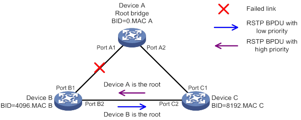
PVST
In an STP- or RSTP-enabled LAN, all bridges share one spanning tree. Traffic from all VLANs is forwarded along the spanning tree, and ports cannot be blocked on a per-VLAN basis to prune loops.
PVST allows every VLAN to have its own spanning tree, which increases usage of links and bandwidth. Because each VLAN runs RSTP independently, a spanning tree only serves its VLAN.
A PVST-enabled H3C device can communicate with a third-party device that is running Rapid PVST or PVST. The PVST-enabled H3C device supports fast network convergence like RSTP when connected to PVST-enabled H3C devices or third-party devices enabled with Rapid PVST.
PVST protocol frames
As shown in Figure 28, a PVST BPDU uses the same format as an RSTP BPDU except the following differences:
· The destination MAC address of a PVST BPDU is 01-00-0c-cc-cc-cd, which is a private MAC address.
· Each PVST BPDU carries a VLAN tag. The VLAN tag identifies the VLAN to which the PVST BPDU belongs.
· The organization code and PID fields are added to the LLC header of the PVST BPDU.
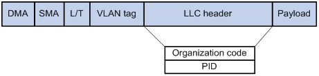
A port's link type determines the type of BPDUs the port sends.
· An access port sends RSTP BPDUs.
· A trunk or hybrid port sends RSTP BPDUs in the default VLAN and sends PVST BPDUs in other VLANs.
Basic concepts in PVST
PVST uses the same port roles and port states as RSTP for fast convergence. For more information, see "Basic concepts in RSTP."
How PVST works
In PVST, each VLAN runs RSTP independently to maintain its own spanning tree without affecting the spanning trees of other VLANs. In this way, loops in each VLAN are eliminated and traffic of different VLANs is load shared over links. PVST uses RSTP BPDUs in the default VLAN and PVST BPDUs in other VLANs for spanning tree calculation. H3C PVST implements per-VLAN spanning tree calculation by mapping each VLAN to an MSTI.
MSTP
MSTP overcomes the following STP, RSTP, and PVST limitations:
· STP limitations—STP does not support rapid state transition of ports. A newly elected port must wait twice the forward delay time before it transits to the forwarding state.
· RSTP limitations—Although RSTP enables faster network convergence than STP, RSTP fails to provide load balancing among VLANs. As with STP, all RSTP bridges in a LAN share one spanning tree and forward frames from all VLANs along this spanning tree.
· PVST limitations—Because each VLAN has its spanning tree, the amount of PVST BPDUs is proportional to the number of VLANs on a trunk or hybrid port. When the trunk or hybrid port permits too many VLANs, both resources and calculations for maintaining the VLAN spanning trees increase dramatically. If a status change occurs on the trunk or hybrid port that permits multiple VLANs, the device CPU will be overburdened with recalculating the affected spanning trees. As a result, network performance is degraded.
MSTP features
Developed based on IEEE 802.1s, MSTP overcomes the limitations of STP, RSTP, and PVST. In addition to supporting rapid network convergence, it allows data flows of different VLANs to be forwarded along separate paths. This provides a better load sharing mechanism for redundant links.
MSTP provides the following features:
· MSTP divides a switched network into multiple regions, each of which contains multiple spanning trees that are independent of one another.
· MSTP supports mapping VLANs to spanning tree instances by means of a VLAN-to-instance mapping table. MSTP can reduce communication overheads and resource usage by mapping multiple VLANs to one instance.
· MSTP prunes a loop network into a loop-free tree, which avoids proliferation and endless cycling of frames in a loop network. In addition, it supports load balancing of VLAN data by providing multiple redundant paths for data forwarding.
· MSTP is compatible with STP and RSTP, and partially compatible with PVST.
MSTP protocol frames
Figure 29 shows the format of an MSTP BPDU.
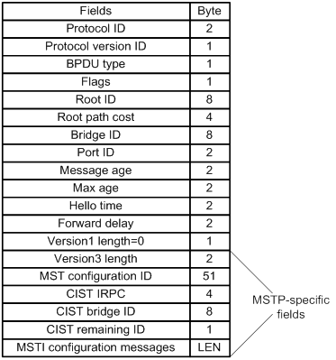
The first 13 fields of an MSTP BPDU are the same as an RSTP BPDU. The other six fields are unique to MSTP.
· Protocol version ID—The value is 0x03 for MSTP.
· BPDU type—The value is 0x02 for RSTP/MSTP BPDUs.
· Root ID—ID of the common root bridge.
· Root path cost—CIST external path cost.
· Bridge ID—ID of the regional root for the IST or an MSTI.
· Port ID—ID of the designated port in the CIST.
· Version3 length—Length of the MSTP-specific fields. Devices use this field for verification upon receiving an MSTP BPDU.
· MST configuration ID—Includes the format selector, configuration name, revision level, and configuration digest. The value for format selector is fixed at 0x00. The other parameters are used to identify the MST region for the originating bridge.
· CIST IRPC—Internal root path cost (IRPC) from the originating bridge to the root of the MST region.
· CIST bridge ID—ID of the bridge that sends the MSTP BPDU.
· CIST remaining ID—Remaining hop count. This field limits the scale of the MST region. The regional root sends a BPDU with the remaining hop count set to the maximum value. Each device that receives the BPDU decrements the hop count by one. When the hop count reaches zero, the BPDU is discarded. Devices beyond the maximum hops of the MST region cannot participate in spanning tree calculation. The default remaining hop count is 20.
· MSTI configuration messages—Contains MSTI configuration messages. Each MSTI configuration message is 16 bytes. This field can contain 0 to 64 MSTI configuration messages. The number of the MSTI configuration messages is determined by the number of MSTIs in the MST region.
MSTP basic concepts
Figure 30 shows a switched network that contains four MST regions, each MST region containing four MSTP devices. Figure 31 shows the networking topology of MST region 3.
Figure 30 Basic concepts in MSTP
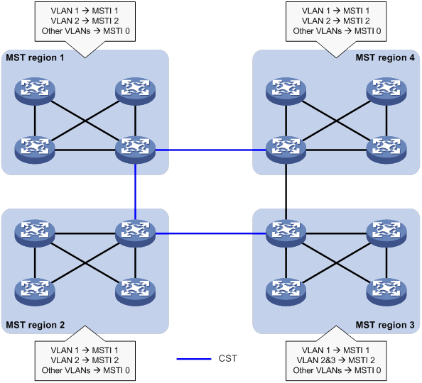
Figure 31 Network diagram and topology of MST region 3
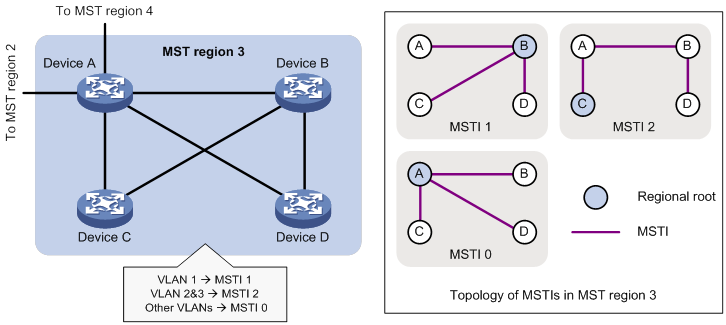
MST region
A multiple spanning tree region (MST region) consists of multiple devices in a switched network and the network segments among them. All these devices have the following characteristics:
· A spanning tree protocol enabled
· Same region name
· Same VLAN-to-instance mapping configuration
· Same MSTP revision level
· Physically linked together
Multiple MST regions can exist in a switched network. You can assign multiple devices to the same MST region, as shown in Figure 30.
· The switched network contains four MST regions, MST region 1 through MST region 4.
· All devices in each MST region have the same MST region configuration.
MSTI
MSTP can generate multiple independent spanning trees in an MST region, and each spanning tree is mapped to the specific VLANs. Each spanning tree is referred to as a multiple spanning tree instance (MSTI).
In Figure 31, MST region 3 contains three MSTIs, MSTI 1, MSTI 2, and MSTI 0.
VLAN-to-instance mapping table
As an attribute of an MST region, the VLAN-to-instance mapping table describes the mapping relationships between VLANs and MSTIs.
In Figure 31, the VLAN-to-instance mapping table of MST region 3 is as follows:
· VLAN 1 to MSTI 1.
· VLAN 2 and VLAN 3 to MSTI 2.
· Other VLANs to MSTI 0.
MSTP achieves load balancing by means of the VLAN-to-instance mapping table.
CST
The common spanning tree (CST) is a single spanning tree that connects all MST regions in a switched network. If you regard each MST region as a device, the CST is a spanning tree calculated by these devices through STP or RSTP.
The blue lines in Figure 30 represent the CST.
IST
An internal spanning tree (IST) is a spanning tree that runs in an MST region. It is also called MSTI 0, a special MSTI to which all VLANs are mapped by default.
In Figure 30, MSTI 0 is the IST in MST region 3.
CIST
The common and internal spanning tree (CIST) is a single spanning tree that connects all devices in a switched network. It consists of the ISTs in all MST regions and the CST.
In Figure 30, the ISTs (MSTI 0) in all MST regions plus the inter-region CST constitute the CIST of the entire network.
Regional root
The root bridge of the IST or an MSTI within an MST region is the regional root of the IST or MSTI. Based on the topology, different spanning trees in an MST region might have different regional roots, as shown in MST region 3 in Figure 31.
· The regional root of MSTI 1 is Device B.
· The regional root of MSTI 2 is Device C.
· The regional root of MSTI 0 (also known as the IST) is Device A.
Common root bridge
The common root bridge is the root bridge of the CIST.
In Figure 30, the common root bridge is a device in MST region 1.
Port roles
A port can play different roles in different MSTIs. As shown in Figure 32, an MST region contains Device A, Device B, Device C, and Device D. Port A1 and port A2 of Device A connect to the common root bridge. Port B2 and Port B3 of Device B form a loop. Port C3 and Port C4 of Device C connect to other MST regions. Port D3 of Device D directly connects to a host.
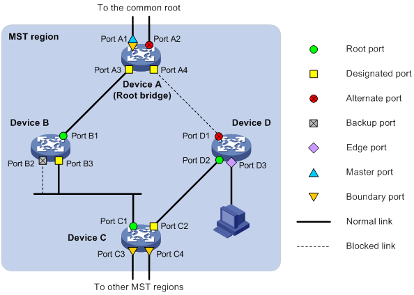
MSTP calculation involves the following port roles:
· Root port—Forwards data for a non-root bridge to the root bridge. The root bridge does not have any root port.
· Designated port—Forwards data to the downstream network segment or device.
· Alternate port—Acts as the backup port for a root port or master port. When the root port or master port is blocked, the alternate port takes over.
· Backup port—Acts as the backup port of a designated port. When the designated port is invalid, the backup port becomes the new designated port. A loop occurs when two ports of the same spanning tree device are connected, so the device blocks one of the ports. The blocked port acts as the backup.
· Edge port—Directly connects to a user host rather than a network device or network segment.
· Master port—Acts as a port on the shortest path from the local MST region to the common root bridge. The master port is not always located on the regional root. It is a root port on the IST or CIST and still a master port on the other MSTIs.
· Boundary port—Connects an MST region to another MST region or to an STP/RSTP-running device. In MSTP calculation, a boundary port's role on an MSTI is consistent with its role on the CIST. However, that is not true with master ports. A master port on MSTIs is a root port on the CIST.
Port states
In MSTP, a port can be in one of the following states:
· Forwarding—The port receives and sends BPDUs, learns MAC addresses, and forwards user traffic.
· Learning—The port receives and sends BPDUs, learns MAC addresses, but does not forward user traffic. Learning is an intermediate port state.
· Discarding—The port receives and sends BPDUs, but does not learn MAC addresses or forward user traffic.
|
|
NOTE: When in different MSTIs, a port can be in different states. |
A port state is not exclusively associated with a port role. Table 10 lists the port states that each port role supports. (A check mark [√] indicates that the port supports this state, while a dash [—] indicates that the port does not support this state.)
Table 10 Port states that different port roles support
|
Port role (right) Port state (below) |
Root port/master port |
Designated port |
Alternate port |
Backup port |
|
Forwarding |
√ |
√ |
— |
— |
|
Learning |
√ |
√ |
— |
— |
|
Discarding |
√ |
√ |
√ |
√ |
How MSTP works
MSTP divides an entire Layer 2 network into multiple MST regions, which are connected by a calculated CST. Inside an MST region, multiple spanning trees, called MSTIs, are calculated. Among these MSTIs, MSTI 0 is the IST.
Like STP, MSTP uses configuration BPDUs to calculate spanning trees. An important difference is that an MSTP BPDU carries the MSTP configuration of the bridge from which the BPDU is sent.
CIST calculation
During the CIST calculation, the following process takes place:
· The device with the highest priority is elected as the root bridge of the CIST.
· MSTP generates an IST within each MST region through calculation.
· MSTP regards each MST region as a single device and generates a CST among these MST regions through calculation.
The CST and ISTs constitute the CIST of the entire network.
MSTI calculation
Within an MST region, MSTP generates different MSTIs for different VLANs based on the VLAN-to-instance mappings. For each spanning tree, MSTP performs a separate calculation process similar to spanning tree calculation in STP. For more information, see "Calculation process of the STP algorithm."
In MSTP, a VLAN frame is forwarded along the following paths:
· Within an MST region, the frame is forwarded along the corresponding MSTI.
· Between two MST regions, the frame is forwarded along the CST.
MSTP implementation on devices
MSTP is compatible with STP and RSTP. Devices that are running MSTP and that are used for spanning tree calculation can identify STP and RSTP protocol frames.
In addition to basic MSTP features, the following features are provided for ease of management:
· Root bridge hold
· Root bridge backup
· Root guard
· BPDU guard
· TC-BPDU guard
· Port role restriction
· TC-BPDU transmission restriction
Rapid transition mechanism
In STP, a port must wait twice the forward delay (30 seconds by default) before it transits from the blocking state to the forwarding state. The forward delay is related to the hello time and network diameter. If the forward delay is too short, loops might occur. This affects the stability of the network.
RSTP, PVST, and MSTP all use the rapid transition mechanism to speed up port state transition for edge ports, root ports, and designated ports. The rapid transition mechanism for designated ports is also known as the proposal/agreement (P/A)_transition.
Edge port rapid transition
As shown in Figure 33, Port C3 is an edge port connected to a host. When a network topology change occurs, the port can immediately transit from the blocking state to the forwarding state because no loop will be caused.
Because a device cannot determine whether a port is directly connected to a terminal, you must manually configure the port as an edge port.
Figure 33 Edge port rapid transition
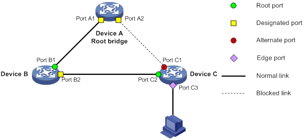
Root port rapid transition
When a root port is blocked, the bridge will elect the alternate port with the highest priority as the new root port. If the new root port's peer is in the forwarding state, the new root port immediately transits to the forwarding state.
As shown in Figure 34, Port C2 on Device C is a root port and Port C1 is an alternate port. When Port C2 transits to the blocking state, Port C1 is elected as the root port and immediately transits to the forwarding state.
Figure 34 Root port rapid transition
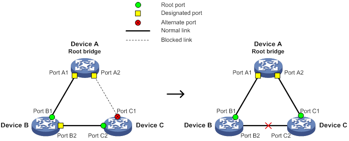
P/A transition
The P/A transition enables a designated port to rapidly transit to the forwarding state after a handshake with its peer. The P/A transition applies only to point-to-point links.
· P/A transition for RSTP and PVST.
In RSTP or PVST, the ports on a new link or recovered link are designated ports in blocking state. When one of the designated ports transits to the discarding or learning state, it sets the proposal flag in its BPDU. Its peer bridge receives the BPDU and determines whether the receiving port is the root port. If it is the root port, the bridge blocks the other ports except edge ports. The bridge then replies an agreement BPDU to the designated port. The designated port immediately transits to the forwarding state upon receiving the agreement BPDU. If the designated port does not receive the agreement BPDU, it waits for twice the forward delay to transit to the forwarding state.
As shown in Figure 35, the P/A transition operates as follows:
a. Device A sends a proposal BPDU to Device B through Port A1.
b. Device B receives the proposal BPDU on Port B2. Port B2 is elected as the root port.
c. Device B blocks its designated port Port B1 and alternate port Port B3 to eliminate loops.
d. The root port Port B2 transits to the forwarding state and sends an agreement BPDU to Device A.
e. The designated port Port A1 on Device A immediately transits to the forwarding state after receiving the agreement BPDU.
Figure 35 P/A transition for RSTP and PVST
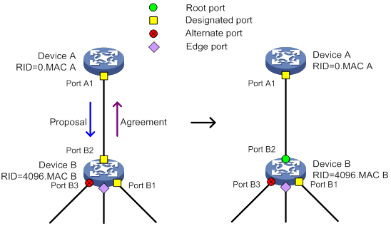
· P/A transition for MSTP.
In MSTP, an upstream bridge sets both the proposal and agreement flags in its BPDU. If a downstream bridge receives the BPDU and its receiving port is elected as the root port, the bridge blocks all the other ports except edge ports. The downstream bridge then replies an agreement BPDU to the upstream bridge. The upstream port immediately transits to the forwarding state upon receiving the agreement BPDU. If the upstream port does not receive the agreement BPDU, it waits for twice the forward delay to transit to the forwarding state.
As shown in Figure 36, the P/A transition operates as follows:
a. Device A sets the proposal and agreement flags in its BPDU and sends it to Device B through Port A1.
b. Device B receives the BPDU. Port B1 of Device B is elected as the root port.
c. Device B then blocks all its ports except the edge ports.
d. The root port Port B1 of Device B transits to the forwarding state and sends an agreement BPDU to Device A.
e. Port A1 of Device A immediately transits to the forwarding state upon receiving the agreement BPDU.
Figure 36 P/A transition for MSTP
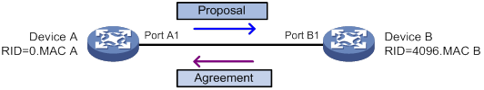
Protocols and standards
MSTP is documented in the following protocols and standards:
· IEEE 802.1d, Media Access Control (MAC) Bridges
· IEEE 802.1w, Part 3: Media Access Control (MAC) Bridges—Amendment 2: Rapid Reconfiguration
· IEEE 802.1s, Virtual Bridged Local Area Networks—Amendment 3: Multiple Spanning Trees
· IEEE 802.1Q-REV/D1.3, Media Access Control (MAC) Bridges and Virtual Bridged Local Area Networks —Clause 13: Spanning tree Protocols
Spanning tree configuration task lists
Before configuring a spanning tree, complete the following tasks:
· Determine the spanning tree protocol to be used (STP, RSTP, PVST, or MSTP).
· Plan the device roles (the root bridge or leaf node).
When you configure spanning tree protocols, follow these restrictions and guidelines:
· The spanning tree configurations are mutually exclusive with any of the following features on a port: service loopback group, RRPP, and Smart Link.
· Configurations made in system view take effect globally. Configurations made in Ethernet interface view take effect only on the interface. Configurations made in Layer 2 aggregate interface view take effect only on the aggregate interface. Configurations made on an aggregation member port can take effect only after the port is removed from the aggregation group.
· After you enable a spanning tree protocol on a Layer 2 aggregate interface, the system performs spanning tree calculation on the Layer 2 aggregate interface. It does not perform spanning tree calculation on the aggregation member ports. The spanning tree protocol enable state and forwarding state of each selected member port is consistent with those of the corresponding Layer 2 aggregate interface.
· The member ports of an aggregation group do not participate in spanning tree calculation. However, the ports still reserve their spanning tree configurations for participating in spanning tree calculation after leaving the aggregation group.
STP configuration task list
|
Tasks at a glance |
|
Configuring the root bridge: · (Required.) Setting the spanning tree mode · (Optional.) Configuring the root bridge or a secondary root bridge · (Optional.) Configuring the device priority · (Optional.) Configuring the network diameter of a switched network · (Optional.) Setting spanning tree timers · (Optional.) Setting the timeout factor · (Optional.) Configuring the BPDU transmission rate · (Optional.) Enabling outputting port state transition information · (Required.) Enabling the spanning tree feature |
|
Configuring the leaf nodes: · (Required.) Setting the spanning tree mode · (Optional.) Configuring the device priority · (Optional.) Setting the timeout factor · (Optional.) Configuring the BPDU transmission rate · (Optional.) Configuring path costs of ports · (Optional.) Configuring the port priority · (Optional.) Enabling outputting port state transition information · (Required.) Enabling the spanning tree feature |
|
(Optional.) Configuring TC Snooping |
|
(Optional.) Configuring protection features |
|
(Optional.) Enabling SNMP notifications for new-root election and topology change events |
RSTP configuration task list
|
Tasks at a glance |
|
Configuring the root bridge: · (Required.) Setting the spanning tree mode · (Optional.) Configuring the root bridge or a secondary root bridge · (Optional.) Configuring the device priority · (Optional.) Configuring the network diameter of a switched network · (Optional.) Setting spanning tree timers · (Optional.) Setting the timeout factor · (Optional.) Configuring the BPDU transmission rate · (Optional.) Configuring edge ports · (Optional.) Configuring the port link type · (Optional.) Enabling outputting port state transition information · (Required.) Enabling the spanning tree feature |
|
Configuring the leaf nodes: · (Required.) Setting the spanning tree mode · (Optional.) Configuring the device priority · (Optional.) Setting the timeout factor · (Optional.) Configuring the BPDU transmission rate · (Optional.) Configuring edge ports · (Optional.) Configuring path costs of ports · (Optional.) Configuring the port priority · (Optional.) Configuring the port link type · (Optional.) Enabling outputting port state transition information · (Required.) Enabling the spanning tree feature |
|
(Optional.) Performing mCheck |
|
(Optional.) Configuring TC Snooping |
|
(Optional.) Configuring protection features |
|
(Optional.) Enabling SNMP notifications for new-root election and topology change events |
PVST configuration task list
|
Tasks at a glance |
|
Configuring the root bridge: · (Required.) Setting the spanning tree mode · (Optional.) Configuring the root bridge or a secondary root bridge · (Optional.) Configuring the device priority · (Optional.) Configuring the network diameter of a switched network · (Optional.) Setting spanning tree timers · (Optional.) Setting the timeout factor · (Optional.) Configuring the BPDU transmission rate · (Optional.) Configuring edge ports · (Optional.) Configuring the port link type · (Optional.) Enabling outputting port state transition information · (Required.) Enabling the spanning tree feature |
|
Configuring the leaf nodes: · (Required.) Setting the spanning tree mode · (Optional.) Configuring the device priority · (Optional.) Setting the timeout factor · (Optional.) Configuring the BPDU transmission rate · (Optional.) Configuring edge ports · (Optional.) Configuring path costs of ports · (Optional.) Configuring the port priority · (Optional.) Configuring the port link type · (Optional.) Enabling outputting port state transition information · (Required.) Enabling the spanning tree feature |
|
(Optional.) Performing mCheck |
|
(Optional.) Disabling inconsistent PVID protection |
|
(Optional.) Configuring protection features |
|
(Optional.) Enabling the device to log events of detecting or receiving TC BPDUs |
|
(Optional.) Enabling SNMP notifications for new-root election and topology change events |
MSTP configuration task list
|
Tasks at a glance |
|
Configuring the root bridge: · (Required.) Setting the spanning tree mode · (Required.) Configuring an MST region · (Optional.) Configuring the root bridge or a secondary root bridge · (Optional.) Configuring the device priority · (Optional.) Configuring the maximum hops of an MST region · (Optional.) Configuring the network diameter of a switched network · (Optional.) Setting spanning tree timers · (Optional.) Setting the timeout factor · (Optional.) Configuring the BPDU transmission rate · (Optional.) Configuring edge ports · (Optional.) Configuring the port link type · (Optional.) Configuring the mode a port uses to recognize and send MSTP frames · (Optional.) Enabling outputting port state transition information · (Required.) Enabling the spanning tree feature |
|
Configuring the leaf nodes: · (Required.) Setting the spanning tree mode · (Required.) Configuring an MST region · (Optional.) Configuring the device priority · (Optional.) Setting the timeout factor · (Optional.) Configuring the BPDU transmission rate · (Optional.) Configuring edge ports · (Optional.) Configuring path costs of ports · (Optional.) Configuring the port priority · (Optional.) Configuring the port link type · (Optional.) Configuring the mode a port uses to recognize and send MSTP frames · (Optional.) Enabling outputting port state transition information · (Required.) Enabling the spanning tree feature |
|
(Optional.) Performing mCheck |
|
(Optional.) Configuring Digest Snooping |
|
(Optional.) Configuring No Agreement Check |
|
(Optional.) Configuring TC Snooping |
|
(Optional.) Configuring protection features |
|
(Optional.) Enabling SNMP notifications for new-root election and topology change events |
Setting the spanning tree mode
The spanning tree modes include:
· STP mode—All ports of the device send STP BPDUs. Select this mode when the peer device of a port supports only STP.
· RSTP mode—All ports of the device send RSTP BPDUs. A port in this mode automatically transits to the STP mode when it receives STP BPDUs from the peer device. A port in this mode does not transit to the MSTP mode when it receives MSTP BPDUs from the peer device.
· PVST mode—All ports of the device send PVST BPDUs. Each VLAN maintains a spanning tree. In a network, the amount of spanning trees maintained by all devices equals the number of PVST-enabled VLANs multiplied by the number of PVST-enabled ports. If the amount of spanning trees exceeds the capacity of the network, device CPUs will be overloaded. Packet forwarding is interrupted, and the network becomes unstable. The device supports a maximum of 128 spanning tree-enabled VLANs.
· MSTP mode—All ports of the device send MSTP BPDUs. A port in this mode automatically transits to the STP mode when receiving STP BPDUs from the peer device. A port in this mode does not transit to the RSTP mode when receiving RSTP BPDUs from the peer device.
The MSTP mode is compatible with the RSTP mode, and the RSTP mode is compatible with the STP mode.
Compatibility of the PVST mode depends on the link type of a port.
· On an access port, the PVST mode is compatible with other spanning tree modes in all VLANs.
· On a trunk port or hybrid port, the PVST mode is compatible with other spanning tree modes only in the default VLAN.
To set the spanning tree mode:
|
Step |
Command |
Remarks |
|
1. Enter system view. |
system-view |
N/A |
|
2. Set the spanning tree mode. |
stp mode { mstp | pvst | rstp | stp } |
The default setting is the MSTP mode. |
Configuring an MST region
Spanning tree devices belong to the same MST region if they are both connected through a physical link and configured with the following details:
· Format selector (0 by default, not configurable).
· MST region name.
· MST region revision level.
· VLAN-to-instance mapping entries in the MST region.
The configuration of MST region-related parameters (especially the VLAN-to-instance mapping table) might cause MSTP to begin a new spanning tree calculation. To reduce the possibility of topology instability, the MST region configuration takes effect only after you activate it by doing one of the following:
· Use the active region-configuration command.
· Enable a spanning tree protocol by using the stp global enable command if the spanning tree protocol is disabled.
In STP, RSTP, or PVST mode, MST region configurations do not take effect.
To configure an MST region:
|
Step |
Command |
Remarks |
|
1. Enter system view. |
system-view |
N/A |
|
2. Enter MST region view. |
stp region-configuration |
N/A |
|
3. Configure the MST region name. |
region-name name |
The default setting is the MAC address. |
|
4. Configure the VLAN-to-instance mapping table. |
· instance instance-id vlan vlan-id-list · vlan-mapping modulo modulo |
Use one of the commands. By default, all VLANs in an MST region are mapped to the CIST (or MSTI 0). |
|
5. Configure the MSTP revision level of the MST region. |
revision-level level |
The default setting is 0. |
|
6. (Optional.) Display the MST region configurations that are not activated yet. |
check region-configuration |
N/A |
|
7. Manually activate MST region configuration. |
active region-configuration |
N/A |
Configuring the root bridge or a secondary root bridge
You can have the spanning tree protocol determine the root bridge of a spanning tree through calculation. You can also specify a device as the root bridge or as a secondary root bridge.
A device has independent roles in different spanning trees. It can act as the root bridge in one spanning tree and as a secondary root bridge in another. However, one device cannot be the root bridge and a secondary root bridge in the same spanning tree.
A spanning tree can have only one root bridge. If multiple devices can be selected as the root bridge in a spanning tree, the device with the lowest MAC address is selected.
When the root bridge of an instance fails or is shut down and no new root bridge is specified, the following events occur:
· If you specify only one secondary root bridge, it becomes the root bridge.
· If you specify multiple secondary root bridges for the instance, the secondary root bridge with the lowest MAC address is given priority.
· If you do not specify a secondary root bridge, a new root bridge is calculated.
You can specify one root bridge for each spanning tree, regardless of the device priority settings. Once you specify a device as the root bridge or a secondary root bridge, you cannot change its priority.
You can configure a device as the root bridge by setting the device priority to 0. For the device priority configuration, see "Configuring the device priority."
Configuring the device as the root bridge of a specific spanning tree
|
Step |
Command |
Remarks |
|
1. Enter system view. |
system-view |
N/A |
|
2. Configure the device as the root bridge. |
·
In STP/RSTP mode: ·
In PVST mode: ·
In MSTP mode: |
By default, the device is not a root bridge. |
Configuring the device as a secondary root bridge of a specific spanning tree
|
Step |
Command |
Remarks |
|
1. Enter system view. |
system-view |
N/A |
|
2. Configure the device as a secondary root bridge. |
·
In STP/RSTP mode: ·
In PVST mode: ·
In MSTP mode: |
By default, the device is not a secondary root bridge. |
Configuring the device priority
Device priority is a factor in calculating the spanning tree. The priority of a device determines whether the device can be elected as the root bridge of a spanning tree. A lower value indicates a higher priority. You can set the priority of a device to a low value to specify the device as the root bridge of the spanning tree. A spanning tree device can have different priorities in different spanning trees.
During root bridge selection, if all devices in a spanning tree have the same priority, the one with the lowest MAC address is selected. You cannot change the priority of a device after it is configured as the root bridge or as a secondary root bridge.
To configure the priority of the device in a specified MSTI:
|
Step |
Command |
Remarks |
|
1. Enter system view. |
system-view |
N/A |
|
2. Configure the priority of the device. |
·
In STP/RSTP mode: ·
In PVST mode: ·
In MSTP mode: |
The default setting is 32768. |
Configuring the maximum hops of an MST region
Restrict the region size by setting the maximum hops of an MST region. The hop limit configured on the regional root bridge is used as the hop limit for the MST region.
Configuration BPDUs sent by the regional root bridge always have a hop count set to the maximum value. When a device receives this configuration BPDU, it decrements the hop count by one, and uses the new hop count in the BPDUs that it propagates. When the hop count of a BPDU reaches zero, it is discarded by the device that received it. Devices beyond the reach of the maximum hops can no longer participate in spanning tree calculations, so the size of the MST region is limited.
Make this configuration only on the root bridge. All other devices in the MST region use the maximum hop value set for the root bridge.
You can configure the maximum hops of an MST region based on the STP network size. As a best practice, set the maximum hops to a value that is greater than the maximum hops of each edge device to the root bridge.
To configure the maximum number of hops of an MST region:
|
Step |
Command |
Remarks |
|
1. Enter system view. |
system-view |
N/A |
|
2. Configure the maximum hops of the MST region. |
stp max-hops hops |
The default setting is 20. |
Configuring the network diameter of a switched network
Any two terminal devices in a switched network can reach each other through a specific path, and there are a series of devices on the path. The switched network diameter is the maximum number of devices on the path for an edge device to reach another one in the switched network through the root bridge. The network diameter indicates the network size. The bigger the diameter, the larger the network size.
Based on the network diameter you configured, the system automatically sets an optimal hello time, forward delay, and max age for the device.
In STP, RSTP, or MSTP mode, each MST region is considered a device. The configured network diameter takes effect only on the CIST (or the common root bridge) but not on other MSTIs.
In PVST mode, the configured network diameter takes effect only on the root bridges of the specified VLANs.
To configure the network diameter of a switched network:
|
Step |
Command |
Remarks |
|
1. Enter system view. |
system-view |
N/A |
|
2. Configure the network diameter of the switched network. |
·
In STP/RSTP/MSTP mode: ·
In PVST mode: |
The default setting is 7. |
Setting spanning tree timers
The following timers are used for spanning tree calculation:
· Forward delay—Delay time for port state transition. To prevent temporary loops on a network, the spanning tree feature sets an intermediate port state (the learning state) before it transits from the discarding state to the forwarding state. The feature also requires that the port transit its state after a forward delay timer. This ensures that the state transition of the local port stays synchronized with the peer.
· Hello time—Interval at which the device sends configuration BPDUs to detect link failures. If the device does not receive configuration BPDUs within the timeout period, it recalculates the spanning tree. The formula for calculating the timeout period is timeout period = timeout factor × 3 × hello time.
· Max age—In the CIST of an MSTP network, the device uses the max age timer to determine whether a configuration BPDU received by a port has expired. If it is expired, a new spanning tree calculation process starts. The max age timer does not take effect on MSTIs.
To ensure a fast topology convergence, make sure the timer settings meet the following formulas:
· 2 × (forward delay – 1 second) ≥ max age
· Max age ≥ 2 × (hello time + 1 second)
As a best practice, specify the network diameter and letting spanning tree protocols automatically calculate the timers based on the network diameter instead of manually setting the spanning tree timers. If the network diameter uses the default value, the timers also use their default values.
Set the timers only on the root bridge. The timer settings on the root bridge apply to all devices on the entire switched network.
Configuration restrictions and guidelines
When you set spanning tree timers, follow these restrictions and guidelines:
· The length of the forward delay is related to the network diameter of the switched network. The larger the network diameter is, the longer the forward delay time should be. As a best practice, use the automatically calculated value because inappropriate forward delay setting might cause temporary redundant paths or increase the network convergence time.
· An appropriate hello time setting enables the device to promptly detect link failures on the network without using excessive network resources. If the hello time is too long, the device mistakes packet loss for a link failure and triggers a new spanning tree calculation process. If the hello time is too short, the device frequently sends the same configuration BPDUs, which wastes device and network resources. As a best practice, use the automatically calculated value.
· If the max age timer is too short, the device frequently begins spanning tree calculations and might mistake network congestion as a link failure. If the max age timer is too long, the device might fail to promptly detect link failures and quickly launch spanning tree calculations, reducing the auto-sensing capability of the network. As a best practice, use the automatically calculated value.
Configuration procedure
To set the spanning tree timers:
|
Step |
Command |
Remarks |
|
1. Enter system view. |
system-view |
N/A |
|
2. Set the forward delay timer. |
·
In STP/RSTP/MSTP mode: ·
In PVST mode: |
The default setting is 15 seconds. |
|
3. Set the hello timer. |
·
In STP/RSTP/MSTP mode: ·
In PVST mode: |
The default setting is 2 seconds. |
|
4. Set the max age timer. |
·
In STP/RSTP/MSTP mode: ·
In PVST mode: |
The default setting is 20 seconds. |
Setting the timeout factor
The timeout factor is a parameter used to decide the timeout period. The formula for calculating the timeout period is: timeout period = timeout factor × 3 × hello time.
In a stable network, each non-root-bridge device forwards configuration BPDUs to the downstream devices at the hello time interval to detect link failures. If a device does not receive a BPDU from the upstream device within nine times the hello time, it assumes that the upstream device has failed. Then, it starts a new spanning tree calculation process.
As a best practice, set the timeout factor to 5, 6, or 7 in the following situations:
· To prevent undesired spanning tree calculations. An upstream device might be too busy to forward configuration BPDUs in time, for example, many Layer 2 interfaces are configured on the upstream device. In this case, the downstream device fails to receive a BPDU within the timeout period and then starts an undesired spanning tree calculation.
· To save network resources on a stable network.
To set the timeout factor:
|
Step |
Command |
Remarks |
|
1. Enter system view. |
system-view |
N/A |
|
2. Set the timeout factor of the device. |
stp timer-factor factor |
The default setting is 3. |
Configuring the BPDU transmission rate
The maximum number of BPDUs a port can send within each hello time equals the BPDU transmission rate plus the hello timer value. Configure an appropriate BPDU transmission rate based on the physical status of the port and the network structure.
The higher the BPDU transmission rate, the more BPDUs are sent within each hello time, and the more system resources are used. By setting an appropriate BPDU transmission rate, you can limit the rate at which the port sends BPDUs. Setting an appropriate rate also prevents spanning tree protocols from using excessive network resources when the network topology changes. As a best practice, use the default setting.
To configure the BPDU transmission rate:
|
Step |
Command |
Remarks |
|
1. Enter system view. |
system-view |
N/A |
|
2. Enter Layer 2 Ethernet interface or Layer 2 aggregate interface view. |
interface interface-type interface-number |
N/A |
|
3. Configure the BPDU transmission rate of the ports. |
stp transmit-limit limit |
The default setting is 10. |
Configuring edge ports
If a port directly connects to a user terminal rather than another device or a shared LAN segment, this port is regarded as an edge port. When network topology change occurs, an edge port will not cause a temporary loop. Because a device does not determine whether a port is directly connected to a terminal, you must manually configure the port as an edge port. After that, the port can rapidly transit from the blocking state to the forwarding state.
Configuration restrictions and guidelines
When you configure edge ports, follow these restrictions and guidelines:
· If BPDU guard is disabled on a port configured as an edge port, the port becomes a non-edge port again if it receives a BPDU from another port. To restore the edge port, re-enable it.
· If a port directly connects to a user terminal, configure it as an edge port and enable BPDU guard for it. This enables the port to quickly transit to the forwarding state when ensuring network security.
· On a port, the loop guard feature and the edge port setting are mutually exclusive.
Configuration procedure
To configure a port as an edge port:
|
Step |
Command |
Remarks |
|
1. Enter system view. |
system-view |
N/A |
|
2. Enter Layer 2 Ethernet interface or Layer 2 aggregate interface view. |
interface interface-type interface-number |
N/A |
|
3. Configure the port as an edge port. |
stp edged-port |
By default, all ports are non-edge ports. |
Configuring path costs of ports
Path cost is a parameter related to the rate of a port. On a spanning tree device, a port can have different path costs in different MSTIs. Setting appropriate path costs allows VLAN traffic flows to be forwarded along different physical links, achieving VLAN-based load balancing.
You can have the device automatically calculate the default path cost, or you can configure the path cost for ports.
Specifying a standard for the device to use when it calculates the default path cost
|
|
CAUTION: If you change the standard that the device uses to calculate the default path costs, you restore the path costs to the default. |
You can specify a standard for the device to use in automatic calculation for the default path cost. The device supports the following standards:
· dot1d-1998—The device calculates the default path cost for ports based on IEEE 802.1d-1998.
· dot1t—The device calculates the default path cost for ports based on IEEE 802.1t.
· legacy—The device calculates the default path cost for ports based on a private standard.
When you specify a standard for the device to use when it calculates the default path cost, follow these guidelines:
· When it calculates the path cost for an aggregate interface, IEEE 802.1t takes into account the number of Selected ports in its aggregation group. However, IEEE 802.1d-1998 does not take into account the number of Selected ports. The calculation formula of IEEE 802.1t is: Path cost = 200,000,000/link speed (in 100 kbps). The link speed is the sum of the link speed values of the Selected ports in the aggregation group.
· IEEE 802.1d-1998 or the private standard always assigns the smallest possible value to a single port or aggregate interface with a speed exceeding 10 Gbps. The forwarding path selected based on this criterion might not be the best one. To solve this problem, perform one of the following tasks:
? Use dot1t as the standard for default path cost calculation.
? Manually set the path cost for the port (see "Configuring path costs of ports").
To specify a standard for the device to use when it calculates the default path cost:
|
Step |
Command |
Remarks |
|
1. Enter system view. |
system-view |
N/A |
|
2. Specify a standard for the device to use when it calculates the default path costs of its ports. |
stp pathcost-standard { dot1d-1998 | dot1t | legacy } |
By default, the device uses legacy to calculate the default path costs of its ports. |
Table 11 Mappings between the link speed and the path cost
|
Link speed |
Port type |
Path cost |
||
|
IEEE 802.1d-1998 |
IEEE 802.1t |
Private standard |
||
|
0 |
N/A |
65535 |
200000000 |
200000 |
|
10 Mbps |
Single port |
100 |
2000000 |
2000 |
|
Aggregate interface containing two Selected ports |
1000000 |
1800 |
||
|
Aggregate interface containing three Selected ports |
666666 |
1600 |
||
|
Aggregate interface containing four Selected ports |
500000 |
1400 |
||
|
100 Mbps |
Single port |
19 |
200000 |
200 |
|
Aggregate interface containing two Selected ports |
100000 |
180 |
||
|
Aggregate interface containing three Selected ports |
66666 |
160 |
||
|
Aggregate interface containing four Selected ports |
50000 |
140 |
||
|
1000 Mbps |
Single port |
4 |
20000 |
20 |
|
Aggregate interface containing two Selected ports |
10000 |
18 |
||
|
Aggregate interface containing three Selected ports |
6666 |
16 |
||
|
Aggregate interface containing four Selected ports |
5000 |
14 |
||
|
10 Gbps |
Single port |
2 |
2000 |
2 |
|
Aggregate interface containing two Selected ports |
1000 |
1 |
||
|
Aggregate interface containing three Selected ports |
666 |
1 |
||
|
Aggregate interface containing four Selected ports |
500 |
1 |
||
|
20 Gbps |
Single port |
1 |
1000 |
1 |
|
Aggregate interface containing two Selected ports |
500 |
1 |
||
|
Aggregate interface containing three Selected ports |
333 |
1 |
||
|
Aggregate interface containing four Selected ports |
250 |
1 |
||
|
40 Gbps |
Single port |
1 |
500 |
1 |
|
Aggregate interface containing two Selected ports |
250 |
1 |
||
|
Aggregate interface containing three Selected ports |
166 |
1 |
||
|
Aggregate interface containing four Selected ports |
125 |
1 |
||
|
100 Gbps |
Single port |
1 |
200 |
1 |
|
Aggregate interface containing two Selected ports |
100 |
1 |
||
|
Aggregate interface containing three Selected ports |
66 |
1 |
||
|
Aggregate interface containing four Selected ports |
50 |
1 |
||
Configuring path costs of ports
When the path cost of a port changes, the system recalculates the role of the port and initiates a state transition.
To configure the path cost of a port:
|
Step |
Command |
Remarks |
|
1. Enter system view. |
system-view |
N/A |
|
2. Enter Layer 2 Ethernet interface or Layer 2 aggregate interface view. |
interface interface-type interface-number |
N/A |
|
3. Configure the path cost of the ports. |
·
In STP/RSTP mode: ·
In PVST mode: ·
In MSTP mode: |
By default, the system automatically calculates the path cost of each port. |
Configuration example
# In MSTP mode, perform the following tasks:
· Configure the device to calculate the default path costs of its ports by using IEEE 802.1d-1998.
· Set the path cost of HundredGigE 1/0/3 to 200 on MSTI 2.
<Sysname> system-view
[Sysname] stp pathcost-standard dot1d-1998
Cost of every port will be reset and automatically re-calculated after you change the current pathcost standard. Continue?[Y/N]:y
Cost of every port has been re-calculated.
[Sysname] interface hundredgige 1/0/3
[Sysname-HundredGigE1/0/3] stp instance 2 cost 200
# In PVST mode, perform the following tasks:
· Configure the device to calculate the default path costs of its ports by using IEEE 802.1d-1998.
· Set the path cost of HundredGigE 1/0/3 to 2000 on VLAN 20 through VLAN 30.
<Sysname> system-view
[Sysname] stp pathcost-standard dot1d-1998
Cost of every port will be reset and automatically re-calculated after you change the current pathcost standard. Continue?[Y/N]:y
Cost of every port has been re-calculated
[Sysname] interface hundredgige 1/0/3
[Sysname-HundredGigE1/0/3] stp vlan 20 to 30 cost 2000
Configuring the port priority
The priority of a port is a factor that determines whether the port can be elected as the root port of a device. If all other conditions are the same, the port with the highest priority is elected as the root port.
On a spanning tree device, a port can have different priorities and play different roles in different spanning trees. As a result, data of different VLANs can be propagated along different physical paths, implementing per-VLAN load balancing. You can set port priority values based on the actual networking requirements.
When the priority of a port changes, the system recalculates the port role and initiates a state transition.
To configure the priority of a port:
|
Step |
Command |
Remarks |
|
1. Enter system view. |
system-view |
N/A |
|
2. Enter Layer 2 Ethernet interface or Layer 2 aggregate interface view. |
interface interface-type interface-number |
N/A |
|
3. Configure the port priority. |
·
In STP/RSTP mode: ·
In PVST mode: ·
In MSTP mode: |
The default setting is 128 for all ports. |
Configuring the port link type
A point-to-point link directly connects two devices. If two root ports or designated ports are connected over a point-to-point link, they can rapidly transit to the forwarding state after a proposal-agreement handshake process.
Configuration restrictions and guidelines
When you configure the port link type, follow these restrictions and guidelines:
· You can configure the link type as point-to-point for a Layer 2 aggregate interface or a port that operates in full duplex mode. As a best practice, use the default setting and let the device automatically detect the port link type.
· In PVST or MSTP mode, the stp point-to-point force-false or stp point-to-point force-true command configured on a port takes effect on all VLANs or all MSTIs.
· Before you set the link type of a port to point-to-point, make sure the port is connected to a point-to-point link. Otherwise, a temporary loop might occur.
Configuration procedure
To configure the link type of a port:
|
Step |
Command |
Remarks |
|
1. Enter system view. |
system-view |
N/A |
|
2. Enter Layer 2 Ethernet interface or Layer 2 aggregate interface view. |
interface interface-type interface-number |
N/A |
|
3. Configure the port link type. |
stp point-to-point { auto | force-false | force-true } |
By default, the link type is auto where the port automatically detects the link type. |
Configuring the mode a port uses to recognize and send MSTP frames
A port can receive and send MSTP frames in the following formats:
· dot1s—802.1s-compliant standard format
· legacy—Compatible format
By default, the frame format recognition mode of a port is auto. The port automatically distinguishes the two MSTP frame formats, and determines the format of frames that it will send based on the recognized format.
You can configure the MSTP frame format on a port. Then, the port sends only MSTP frames of the configured format to communicate with devices that send frames of the same format.
By default, a port in auto mode sends 802.1s MSTP frames. When the port receives an MSTP frame of a legacy format, the port starts to send frames only of the legacy format. This prevents the port from frequently changing the format of sent frames. To configure the port to send 802.1s MSTP frames, shut down and then bring up the port.
When the number of existing MSTIs exceeds 48, the port can send only 802.1s MSTP frames.
To configure the MSTP frame format to be supported on a port:
|
Step |
Command |
Remarks |
|
1. Enter system view. |
system-view |
N/A |
|
2. Enter Layer 2 Ethernet interface or Layer 2 aggregate interface view. |
interface interface-type interface-number |
N/A |
|
3. Configure the mode that the port uses to recognize/send MSTP frames. |
stp compliance { auto | dot1s | legacy } |
The default setting is auto. |
Enabling outputting port state transition information
In a large-scale spanning tree network, you can enable devices to output the port state transition information. Then, you can monitor the port states in real time.
To enable outputting port state transition information:
|
Step |
Command |
Remarks |
|
1. Enter system view. |
system-view |
N/A |
|
2. Enable outputting port state transition information. |
·
In STP/RSTP mode: ·
In PVST mode: ·
In MSTP mode: |
By default, this feature is enabled. |
Enabling the spanning tree feature
You must enable the spanning tree feature for the device before any other spanning tree related configurations can take effect. In STP, RSTP, or MSTP mode, make sure the spanning tree feature is enabled globally and on the desired ports. In PVST mode, make sure the spanning tree feature is enabled globally, in the desired VLANs, and on the desired ports.
To exclude specific ports from spanning tree calculation and save CPU resources, disable the spanning tree feature for these ports with the undo stp enable command. Make sure no loops occur in the network after you disable the spanning tree feature on these ports.
Enabling the spanning tree feature in STP/RSTP/MSTP mode
|
Step |
Command |
Remarks |
|
1. Enter system view. |
system-view |
N/A |
|
2. Enable the spanning tree feature. |
stp global enable |
By default, the spanning tree feature is globally disabled. |
|
3. Enter Layer 2 Ethernet interface or Layer 2 aggregate interface view. |
interface interface-type interface-number |
N/A |
|
4. (Optional.) Enable the spanning tree feature for the port. |
stp enable |
By default, the spanning tree feature is enabled on all ports. |
Enabling the spanning tree feature in PVST mode
|
Step |
Command |
Remarks |
|
1. Enter system view. |
system-view |
N/A |
|
2. Enable the spanning tree feature. |
stp global enable |
By default, the spanning tree feature is globally disabled. |
|
3. Enable the spanning tree feature in VLANs. |
stp vlan vlan-id-list enable |
By default, the spanning tree feature is enabled in VLANs. |
|
4. Enter Layer 2 Ethernet interface or Layer 2 aggregate interface view. |
interface interface-type interface-number |
N/A |
|
5. Enable the spanning tree feature on the port. |
stp enable |
By default, the spanning tree feature is enabled on all ports. |
Performing mCheck
The mCheck feature enables user intervention in the port status transition process.
When a port on an MSTP, RSTP, or PVST device connects to an STP device and receives STP BPDUs, the port automatically transits to the STP mode. However, the port cannot automatically transit back to the original mode when the following conditions exist:
· The peer STP device is shut down or removed.
· The port cannot detect the change.
To forcibly transit the port to operate in the original mode, you can perform an mCheck operation.
For example, Device A, Device B, and Device C are connected in sequence. Device A runs STP, Device B does not run any spanning tree protocol, and Device C runs RSTP, PVST, or MSTP. In this case, when Device C receives an STP BPDU transparently transmitted by Device B, the receiving port transits to the STP mode. If you configure Device B to run RSTP, PVST, or MSTP with Device C, you must perform mCheck operations on the ports interconnecting Device B and Device C.
Configuration restrictions and guidelines
The mCheck operation takes effect on devices operating in MSTP, PVST, or RSTP mode.
Performing mCheck globally
|
Step |
Command |
|
1. Enter system view. |
system-view |
|
2. Perform mCheck. |
stp global mcheck |
Performing mCheck in interface view
|
Step |
Command |
|
1. Enter system view. |
system-view |
|
2. Enter Layer 2 Ethernet interface or Layer 2 aggregate interface view. |
interface interface-type interface-number |
|
3. Perform mCheck. |
stp mcheck |
Disabling inconsistent PVID protection
In PVST, if two connected ports use different PVIDs, PVST calculation errors might occur. By default, inconsistent PVID protection is enabled to avoid PVST calculation errors. If PVID inconsistency is detected on a port, the system blocks the port.
If different PVIDs are required on two connected ports, disable inconsistent PVID protection on the devices that host the ports. To avoid PVST calculation errors, make sure the following requirements are met:
· Make sure the VLANs on one device do not use the same ID as the PVID of its peer port (except the default VLAN) on another device.
· If the local port or its peer is a hybrid port, do not configure the local and peer ports as untagged members of the same VLAN.
· Disable inconsistent PVID protection on both the local device and the peer device.
This feature takes effect only when the device is operating in PVST mode.
To disable the inconsistent PVID protection feature:
|
Step |
Command |
Remarks |
|
1. Enter system view. |
system-view |
N/A |
|
2. Disable the inconsistent PVID protection feature. |
stp ignore-pvid-inconsistency |
By default, the inconsistent PVID protection feature is enabled. |
Configuring Digest Snooping
|
|
CAUTION: Use caution with global Digest Snooping in the following situations: · When you modify the VLAN-to-instance mappings. · When you restore the default MST region configuration. If the local device has different VLAN-to-instance mappings than its neighboring devices, loops or traffic interruption will occur. |
As defined in IEEE 802.1s, connected devices are in the same region only when they have the same MST region-related configurations, including:
· Region name.
· Revision level.
· VLAN-to-instance mappings.
A spanning tree device identifies devices in the same MST region by determining the configuration ID in BPDUs. The configuration ID includes the region name, revision level, and configuration digest. It is 16-byte long and is the result calculated through the HMAC-MD5 algorithm based on VLAN-to-instance mappings.
Because spanning tree implementations vary by vendor, the configuration digests calculated through private keys are different. The devices of different vendors in the same MST region cannot communicate with each other.
To enable communication between an H3C device and a third-party device in the same MST region, enable Digest Snooping on the H3C device port connecting them.
Configuration restrictions and guidelines
When you configure Digest Snooping, follow these restrictions and guidelines:
· Before you enable Digest Snooping, make sure associated devices of different vendors are connected and run spanning tree protocols.
· With Digest Snooping enabled, in-the-same-region verification does not require comparison of configuration digest. The VLAN-to-instance mappings must be the same on associated ports.
· To make Digest Snooping take effect, you must enable Digest Snooping both globally and on associated ports. As a best practice, enable Digest Snooping on all associated ports first and then enable it globally. This will make the configuration take effect on all configured ports and reduce impact on the network.
· To prevent loops, do not enable Digest Snooping on MST region edge ports.
· As a best practice, enable Digest Snooping first and then enable the spanning tree feature. To avoid traffic interruption, do not configure Digest Snooping when the network is already working well.
Configuration procedure
Use this feature on when your H3C device is connected to a third-party device that uses its private key to calculate the configuration digest.
To configure Digest Snooping:
|
Step |
Command |
Remarks |
|
1. Enter system view. |
system-view |
N/A |
|
2. Enter Layer 2 Ethernet interface or Layer 2 aggregate interface view. |
interface interface-type interface-number |
N/A |
|
3. Enable Digest Snooping on the interface. |
stp config-digest-snooping |
By default, Digest Snooping is disabled on ports. |
|
4. Return to system view. |
quit |
N/A |
|
5. Enable Digest Snooping globally. |
stp global config-digest-snooping |
By default, Digest Snooping is disabled globally. |
Digest Snooping configuration example
Network requirements
As shown in Figure 37, Device A and Device B connect to Device C, which is a third-party device. All these devices are in the same region.
Enable Digest Snooping on the ports of Device A and Device B that connect to Device C, so that the three devices can communicate with one another.
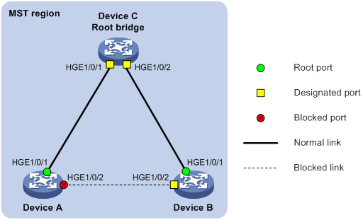
Configuration procedure
# Enable Digest Snooping on HundredGigE 1/0/1 of Device A and enable global Digest Snooping on Device A.
<DeviceA> system-view
[DeviceA] interface hundredgige 1/0/1
[DeviceA-HundredGigE1/0/1] stp config-digest-snooping
[DeviceA-HundredGigE1/0/1] quit
[DeviceA] stp global config-digest-snooping
# Enable Digest Snooping on HundredGigE 1/0/1 of Device B and enable global Digest Snooping on Device B.
<DeviceB> system-view
[DeviceB] interface hundredgige 1/0/1
[DeviceB-HundredGigE1/0/1] stp config-digest-snooping
[DeviceB-HundredGigE1/0/1] quit
[DeviceB] stp global config-digest-snooping
Configuring No Agreement Check
In RSTP and MSTP, the following types of messages are used for rapid state transition on designated ports:
· Proposal—Sent by designated ports to request rapid transition
· Agreement—Used to acknowledge rapid transition requests
Both RSTP and MSTP devices can perform rapid transition on a designated port only when the port receives an agreement packet from the downstream device. RSTP and MSTP devices have the following differences:
· For MSTP, the root port of the downstream device sends an agreement packet only after it receives an agreement packet from the upstream device.
· For RSTP, the downstream device sends an agreement packet whether or not an agreement packet from the upstream device is received.
Figure 38 Rapid state transition of an MSTP designated port
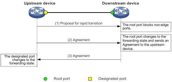
Figure 39 Rapid state transition of an RSTP designated port
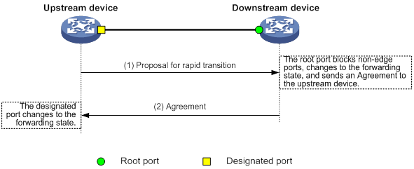
If the upstream device is a third-party device, the rapid state transition implementation might be limited as follows:
· The upstream device uses a rapid transition mechanism similar to that of RSTP.
· The downstream device runs MSTP and does not operate in RSTP mode.
In this case, the following occurs:
1. The root port on the downstream device receives no agreement from the upstream device.
2. It sends no agreement to the upstream device.
As a result, the designated port of the upstream device can transit to the forwarding state only after a period twice the Forward Delay.
To enable the designated port of the upstream device to transit its state rapidly, enable No Agreement Check on the downstream device's port.
Configuration prerequisites
Before you configure the No Agreement Check feature, complete the following tasks:
· Connect a device to a third-party upstream device that supports spanning tree protocols through a point-to-point link.
· Configure the same region name, revision level, and VLAN-to-instance mappings on the two devices.
Configuration procedure
Enable the No Agreement Check feature on the root port.
To configure No Agreement Check:
|
Step |
Command |
Remarks |
|
1. Enter system view. |
system-view |
N/A |
|
2. Enter Layer 2 Ethernet interface or Layer 2 aggregate interface view. |
interface interface-type interface-number |
N/A |
|
3. Enable No Agreement Check. |
stp no-agreement-check |
By default, No Agreement Check is disabled. |
No Agreement Check configuration example
Network requirements
As shown in Figure 40, Device A connects to a third-party device that has a different spanning tree implementation. Both devices are in the same region.
The third-party device (Device B) is the regional root bridge, and Device A is the downstream device.
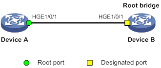
Configuration procedure
# Enable No Agreement Check on HundredGigE 1/0/1 of Device A.
<DeviceA> system-view
[DeviceA] interface hundredgige 1/0/1
[DeviceA-HundredGigE1/0/1] stp no-agreement-check
Configuring TC Snooping
As shown in Figure 41, an IRF fabric connects to two user networks through double links.
· Device A and Device B form the IRF fabric.
· The spanning tree feature is disabled on Device A and Device B and enabled on all devices in user network 1 and user network 2.
· The IRF fabric transparently transmits BPDUs for both user networks and is not involved in the calculation of spanning trees.
When the network topology changes, it takes time for the IRF fabric to update its MAC address table and ARP table. During this period, traffic in the network might be interrupted.
Figure 41 TC Snooping application scenario
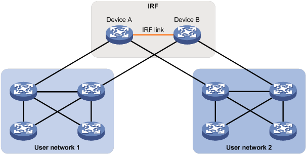
To avoid traffic interruption, you can enable TC Snooping on the IRF fabric. After receiving a TC-BPDU through a port, the IRF fabric updates MAC address table and ARP table entries associated with the port's VLAN. In this way, TC Snooping prevents topology change from interrupting traffic forwarding in the network. For more information about the MAC address table and the ARP table, see "Configuring the MAC address table" and Layer 3—IP Services Configuration Guide.
Configuration restrictions and guidelines
When you configure TC Snooping, follow these restrictions and guidelines:
· TC Snooping and the spanning tree feature are mutually exclusive. You must globally disable the spanning tree feature before enabling TC Snooping.
· TC Snooping does not support the PVST mode.
Configuration procedure
To enable TC Snooping:
|
Step |
Command |
Remarks |
|
1. Enter system view. |
system-view |
N/A |
|
2. Globally disable the spanning tree feature. |
undo stp global enable |
By default, the spanning tree feature is globally disabled. |
|
3. Enable TC Snooping. |
stp tc-snooping |
By default, TC Snooping is disabled. |
Configuring protection features
A spanning tree device supports the following protection features:
· BPDU guard
· Root guard
· Loop guard
· Port role restriction
· TC-BPDU transmission restriction
· TC-BPDU guard
· BPDU drop
· PVST BPDU guard
Configuring BPDU guard
For access layer devices, the access ports can directly connect to the user terminals (such as PCs) or file servers. The access ports are configured as edge ports to allow rapid transition. When these ports receive configuration BPDUs, the system automatically sets the ports as non-edge ports and starts a new spanning tree calculation process. This causes a change of network topology. Under normal conditions, these ports should not receive configuration BPDUs. However, if someone uses configuration BPDUs maliciously to attack the devices, the network will become unstable.
The spanning tree protocol provides the BPDU guard feature to protect the system against such attacks. When edge ports receive configuration BPDUs on a device with BPDU guard enabled, the device performs the following operations:
· Shuts down these ports.
· Notifies the NMS that these ports have been shut down by the spanning tree protocol.
The device reactivates the shutdown ports after a detection interval. For more information about this detection interval, see Fundamentals Configuration Guide.
You can configure the BPDU guard feature globally or on a per-edge port basis.
BPDU guard does not take effect on loopback-testing-enabled ports. For more information about loopback testing, see Interface Configuration Guide.
Enabling BPDU guard globally
The global BPDU guard setting takes effect on all edge ports that are not configured by using the stp port bpdu-protection command.
To enable BPDU guard globally:
|
Step |
Command |
Remarks |
|
1. Enter system view. |
system-view |
N/A |
|
2. Enable BPDU guard globally. |
stp bpdu-protection |
By default, BPDU guard is globally disabled. |
Configuring BPDU guard on an interface
An edge port preferentially uses the port-specific BPDU guard setting. If the port-specific BPDU guard setting is not available, the edge port uses the global BPDU guard setting.
To configure BPDU guard on an interface:
|
Step |
Command |
Remarks |
|
1. Enter system view. |
system-view |
N/A |
|
2. Enter Layer 2 Ethernet interface or Layer 2 aggregate interface view. |
interface interface-type interface-number |
The specified interface must connect to a user terminal rather than other device or shared LAN segment. |
|
3. Configure BPDU guard. |
stp port bpdu-protection { enable | disable } |
By default, BPDU guard is not configured on a per-edge port basis. The status of BPDU guard on an interface is the same as the global BPDU status. |
Enabling root guard
The root bridge and secondary root bridge of a spanning tree should be located in the same MST region. Especially for the CIST, the root bridge and secondary root bridge are put in a high-bandwidth core region during network design. However, due to possible configuration errors or malicious attacks in the network, the legal root bridge might receive a configuration BPDU with a higher priority. Another device supersedes the current legal root bridge, causing an undesired change of the network topology. The traffic that should go over high-speed links is switched to low-speed links, resulting in network congestion.
To prevent this situation, MSTP provides the root guard feature. If root guard is enabled on a port of a root bridge, this port plays the role of designated port on all MSTIs. After this port receives a configuration BPDU with a higher priority from an MSTI, it performs the following operations:
· Immediately sets that port to the listening state in the MSTI.
· Does not forward the received configuration BPDU.
This is equivalent to disconnecting the link connected to this port in the MSTI. If the port receives no BPDUs with a higher priority within twice the forwarding delay, it reverts to its original state.
On a port, the loop guard feature and the root guard feature are mutually exclusive.
Configure root guard on a designated port.
To enable root guard:
|
Step |
Command |
Remarks |
|
1. Enter system view. |
system-view |
N/A |
|
2. Enter Layer 2 Ethernet interface or Layer 2 aggregate interface view. |
interface interface-type interface-number |
N/A |
|
3. Enable the root guard feature. |
stp root-protection |
By default, root guard is disabled. |
Enabling loop guard
By continuing to receive BPDUs from the upstream device, a device can maintain the state of the root port and blocked ports. However, link congestion or unidirectional link failures might cause these ports to fail to receive BPDUs from the upstream devices. In this situation, the device reselects the following port roles:
· Those ports in forwarding state that failed to receive upstream BPDUs become designated ports.
· The blocked ports transit to the forwarding state.
As a result, loops occur in the switched network. The loop guard feature can suppress the occurrence of such loops.
The initial state of a loop guard-enabled port is discarding in every MSTI. When the port receives BPDUs, it transits its state. Otherwise, it stays in the discarding state to prevent temporary loops.
Do not enable loop guard on a port that connects user terminals. Otherwise, the port stays in the discarding state in all MSTIs because it cannot receive BPDUs.
On a port, the loop guard feature is mutually exclusive with the root guard feature or the edge port setting.
Configure loop guard on the root port and alternate ports of a device.
To enable loop guard:
|
Step |
Command |
Remarks |
|
1. Enter system view. |
system-view |
N/A |
|
2. Enter Layer 2 Ethernet interface or Layer 2 aggregate interface view. |
interface interface-type interface-number |
N/A |
|
3. Enable the loop guard feature for the ports. |
stp loop-protection |
By default, loop guard is disabled. |
Configuring port role restriction
|
|
CAUTION: Use this feature with caution, because enabling port role restriction on a port might affect the connectivity of the spanning tree topology. |
The bridge ID change of a device in the user access network might cause a change to the spanning tree topology in the core network. To avoid this problem, you can enable port role restriction on a port. With this feature enabled, when the port receives a superior BPDU, it becomes an alternate port rather than a root port.
Make this configuration on the port that connects to the user access network.
To configure port role restriction:
|
Step |
Command |
Remarks |
|
1. Enter system view. |
system-view |
N/A |
|
2. Enter Layer 2 Ethernet interface or Layer 2 aggregate interface view. |
interface interface-type interface-number |
N/A |
|
3. Enable port role restriction. |
stp role-restriction |
By default, port role restriction is disabled. |
Configuring TC-BPDU transmission restriction
|
|
CAUTION: Enabling TC-BPDU transmission restriction on a port might cause the previous forwarding address table to fail to be updated when the topology changes. |
The topology change to the user access network might cause the forwarding address changes to the core network. When the user access network topology is unstable, the user access network might affect the core network. To avoid this problem, you can enable TC-BPDU transmission restriction on a port. With this feature enabled, when the port receives a TC-BPDU, it does not forward the TC-BPDU to other ports.
Make this configuration on the port that connects to the user access network.
To configure TC-BPDU transmission restriction:
|
Step |
Command |
Remarks |
|
1. Enter system view. |
system-view |
N/A |
|
2. Enter Layer 2 Ethernet interface or Layer 2 aggregate interface view. |
interface interface-type interface-number |
N/A |
|
3. Enable TC-BPDU transmission restriction. |
stp tc-restriction |
By default, TC-BPDU transmission restriction is disabled. |
Enabling TC-BPDU guard
When a device receives topology change (TC) BPDUs (the BPDUs that notify devices of topology changes), it flushes its forwarding address entries. If someone uses TC-BPDUs to attack the device, the device will receive a large number of TC-BPDUs within a short time. Then, the device is busy with forwarding address entry flushing. This affects network stability.
TC-BPDU guard allows you to set the maximum number of immediate forwarding address entry flushes performed within 10 seconds after the device receives the first TC-BPDU. For TC-BPDUs received in excess of the limit, the device performs a forwarding address entry flush when the time period expires. This prevents frequent flushing of forwarding address entries. As a best practice, enable TC-BPDU guard.
To enable TC-BPDU guard:
|
Step |
Command |
Remarks |
|
1. Enter system view. |
system-view |
N/A |
|
2. Enable the TC-BPDU guard feature. |
stp tc-protection |
By default, TC-BPDU guard is enabled. As a best practice, do not disable this feature. |
|
3. (Optional.) Configure the maximum number of forwarding address entry flushes that the device can perform every 10 seconds. |
stp tc-protection threshold number |
The default setting is 6. |
Enabling BPDU drop
In a spanning tree network, every BPDU arriving at the device triggers an STP calculation process and is then forwarded to other devices in the network. Malicious attackers might use the vulnerability to attack the network by forging BPDUs. By continuously sending forged BPDUs, they can make all devices in the network continue performing STP calculations. As a result, problems such as CPU overload and BPDU protocol status errors occur.
To avoid this problem, you can enable BPDU drop on ports. A BPDU drop-enabled port does not receive any BPDUs and is invulnerable to forged BPDU attacks.
To enable BPDU drop on an Ethernet interface:
|
Step |
Command |
Remarks |
|
1. Enter system view. |
system-view |
N/A |
|
2. Enter Layer 2 Ethernet interface view. |
interface interface-type interface-number |
N/A |
|
3. Enable BPDU drop on the interface. |
bpdu-drop any |
By default, BPDU drop is disabled. |
Enabling PVST BPDU guard
An MSTP-enabled device forwards PVST BPDUs as data traffic because it cannot recognize PVST BPDUs. If a PVST-enabled device in another independent network receives the PVST BPDUs, a PVST calculation error might occur. To avoid PVST calculation errors, enable PVST BPDU guard on the MSTP-enabled device. The device shuts down a port if the port receives PVST BPDUs.
To enable PVST BPDU guard:
|
Step |
Command |
Remarks |
|
1. Enter system view. |
system-view |
N/A |
|
2. Enable PVST BPDU guard. |
stp pvst-bpdu-protection |
By default, PVST BPDU guard is disabled. |
Enabling the device to log events of detecting or receiving TC BPDUs
This feature allows the device to generate logs when it detects or receives TC BPDUs. This feature applies only to PVST mode.
To enable the device to log events of detecting or receiving TC BPDUs:
|
Step |
Command |
Remarks |
|
1. Enter system view. |
system-view |
N/A |
|
2. Enable the device to log events of receiving or detecting TC BPDUs. |
stp log enable tc |
By default, the device does not generate logs when it detects or receives TC BPDUs. |
Enabling SNMP notifications for new-root election and topology change events
This task enables the device to generate logs and report new-root election events or spanning tree topology changes to SNMP. For the event notifications to be sent correctly, you must also configure SNMP on the device. For more information about SNMP configuration, see the network management and monitoring configuration guide for the device.
When you use the snmp-agent trap enable stp [ new-root | tc ] command, follow these guidelines:
· The new-root keyword applies only to STP, MSTP, and RSTP modes.
· The tc keyword applies only to PVST mode.
· In STP, MSTP, or RSTP mode, the snmp-agent trap enable stp command enables SNMP notifications for new-root election events.
· In PVST mode, the snmp-agent trap enable stp enables SNMP notifications for spanning tree topology changes.
To enable SNMP notifications for new-root election and topology change events:
|
Step |
Command |
Remarks |
|
1. Enter system view. |
system-view |
N/A |
|
2. Enable SNMP notifications for new-root election events. |
In STP, MSTP, or RSTP mode, execute either of the following commands: · snmp-agent trap enable stp new-root · snmp-agent trap enable stp |
The default settings are as follows: · SNMP notifications are disabled for new-root election events. · In MSTP mode, SNMP notifications are enabled in MSTI 0 and disabled in other MSTIs for spanning tree topology changes. · In PVST mode, SNMP notifications are disabled for spanning tree topology changes in all VLANs. |
|
3. Enable SNMP notifications for spanning tree topology changes. |
In PVST mode, execute either of the following commands: · snmp-agent trap enable stp tc · snmp-agent trap enable stp |
Displaying and maintaining the spanning tree
Execute display commands in any view and reset command in user view.
|
Task |
Command |
|
Display history about ports blocked by spanning tree protection features. |
display stp abnormal-port |
|
Display BPDU statistics on ports. |
display stp bpdu-statistics [ interface interface-type interface-number [ instance instance-list ] ] |
|
Display information about ports shut down by spanning tree protection features. |
display stp down-port |
|
(In standalone mode.) Display the port role calculation history for the specified MSTI or all MSTIs. |
display stp [ instance instance-list | vlan vlan-id-list ] history [ slot slot-number ] |
|
(In IRF mode.) Display the port role calculation history for the specified MSTI or all MSTIs. |
display stp [ instance instance-list | vlan vlan-id-list ] history [ chassis chassis-number slot slot-number ] |
|
(In standalone mode.) Display the incoming and outgoing TC/TCN BPDU statistics by all ports in the specified MSTI or all MSTIs. |
display stp [ instance instance-list | vlan vlan-id-list ] tc [ slot slot-number ] |
|
(In IRF mode.) Display the incoming and outgoing TC/TCN BPDU statistics by all ports in the specified MSTI or all MSTIs. |
display stp [ instance instance-list | vlan vlan-id-list ] tc [ chassis chassis-number slot slot-number ] |
|
(In standalone mode.) Display the spanning tree status and statistics. |
display stp [ instance instance-list | vlan vlan-id-list ] [ interface interface-list | slot slot-number ] [ brief ] |
|
(In IRF mode.) Display the spanning tree status and statistics. |
display stp [ instance instance-list | vlan vlan-id-list ] [ interface interface-list | chassis chassis-number slot slot-number ] [ brief ] |
|
Display the MST region configuration information that has taken effect. |
display stp region-configuration |
|
Display the root bridge information of all MSTIs. |
display stp root |
|
Clear the spanning tree statistics. |
reset stp [ interface interface-list ] |
Spanning tree configuration example
MSTP configuration example
Network requirements
As shown in Figure 42, all devices on the network are in the same MST region. Device A and Device B work at the distribution layer. Device C and Device D work at the access layer.
Configure MSTP so that frames of different VLANs are forwarded along different spanning trees.
· VLAN 10 frames are forwarded along MSTI 1.
· VLAN 30 frames are forwarded along MSTI 3.
· VLAN 40 frames are forwarded along MSTI 4.
· VLAN 20 frames are forwarded along MSTI 0.
VLAN 10 and VLAN 30 are terminated on the distribution layer devices, and VLAN 40 is terminated on the access layer devices. The root bridges of MSTI 1 and MSTI 3 are Device A and Device B, respectively, and the root bridge of MSTI 4 is Device C.
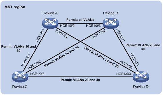
Configuration procedure
1. Configure VLANs and VLAN member ports. (Details not shown.)
? Create VLAN 10, VLAN 20, and VLAN 30 on both Device A and Device B.
? Create VLAN 10, VLAN 20, and VLAN 40 on Device C.
? Create VLAN 20, VLAN 30, and VLAN 40 on Device D.
? Configure the ports on these devices as trunk ports and assign them to related VLANs.
2. Configure Device A:
# Enter MST region view, and configure the MST region name as example.
<DeviceA> system-view
[DeviceA] stp region-configuration
[DeviceA-mst-region] region-name example
# Map VLAN 10, VLAN 30, and VLAN 40 to MSTI 1, MSTI 3, and MSTI 4, respectively.
[DeviceA-mst-region] instance 1 vlan 10
[DeviceA-mst-region] instance 3 vlan 30
[DeviceA-mst-region] instance 4 vlan 40
# Configure the revision level of the MST region as 0.
[DeviceA-mst-region] revision-level 0
# Activate MST region configuration.
[DeviceA-mst-region] active region-configuration
[DeviceA-mst-region] quit
# Configure the Device A as the root bridge of MSTI 1.
[DeviceA] stp instance 1 root primary
# Enable the spanning tree feature globally.
[DeviceA] stp global enable
3. Configure Device B:
# Enter MST region view, and configure the MST region name as example.
<DeviceB> system-view
[DeviceB] stp region-configuration
[DeviceB-mst-region] region-name example
# Map VLAN 10, VLAN 30, and VLAN 40 to MSTI 1, MSTI 3, and MSTI 4, respectively.
[DeviceB-mst-region] instance 1 vlan 10
[DeviceB-mst-region] instance 3 vlan 30
[DeviceB-mst-region] instance 4 vlan 40
# Configure the revision level of the MST region as 0.
[DeviceB-mst-region] revision-level 0
# Activate MST region configuration.
[DeviceB-mst-region] active region-configuration
[DeviceB-mst-region] quit
# Configure Device B as the root bridge of MSTI 3.
[DeviceB] stp instance 3 root primary
# Enable the spanning tree feature globally.
[DeviceB] stp global enable
4. Configure Device C:
# Enter MST region view, and configure the MST region name as example.
<DeviceC> system-view
[DeviceC] stp region-configuration
[DeviceC-mst-region] region-name example
# Map VLAN 10, VLAN 30, and VLAN 40 to MSTI 1, MSTI 3, and MSTI 4, respectively.
[DeviceC-mst-region] instance 1 vlan 10
[DeviceC-mst-region] instance 3 vlan 30
[DeviceC-mst-region] instance 4 vlan 40
# Configure the revision level of the MST region as 0.
[DeviceC-mst-region] revision-level 0
# Activate MST region configuration.
[DeviceC-mst-region] active region-configuration
[DeviceC-mst-region] quit
# Configure the Device C as the root bridge of MSTI 4.
[DeviceC] stp instance 4 root primary
# Enable the spanning tree feature globally.
[DeviceC] stp global enable
5. Configure Device D:
# Enter MST region view, and configure the MST region name as example.
<DeviceD> system-view
[DeviceD] stp region-configuration
[DeviceD-mst-region] region-name example
# Map VLAN 10, VLAN 30, and VLAN 40 to MSTI 1, MSTI 3, and MSTI 4, respectively.
[DeviceD-mst-region] instance 1 vlan 10
[DeviceD-mst-region] instance 3 vlan 30
[DeviceD-mst-region] instance 4 vlan 40
# Configure the revision level of the MST region as 0.
[DeviceD-mst-region] revision-level 0
# Activate MST region configuration.
[DeviceD-mst-region] active region-configuration
[DeviceD-mst-region] quit
# Enable the spanning tree feature globally.
[DeviceD] stp global enable
Verifying the configuration
In this example, Device B has the lowest root bridge ID. As a result, Device B is elected as the root bridge in MSTI 0.
When the network is stable, you can use the display stp brief command to display brief spanning tree information on each device.
# Display brief spanning tree information on Device A.
[DeviceA] display stp brief
MST ID Port Role STP State Protection
0 HundredGigE1/0/1 ALTE DISCARDING NONE
0 HundredGigE1/0/2 DESI FORWARDING NONE
0 HundredGigE1/0/3 ROOT FORWARDING NONE
1 HundredGigE1/0/1 DESI FORWARDING NONE
1 HundredGigE1/0/3 DESI FORWARDING NONE
3 HundredGigE1/0/2 DESI FORWARDING NONE
3 HundredGigE1/0/3 ROOT FORWARDING NONE
# Display brief spanning tree information on Device B.
[DeviceB] display stp brief
MST ID Port Role STP State Protection
0 HundredGigE1/0/1 DESI FORWARDING NONE
0 HundredGigE1/0/2 DESI FORWARDING NONE
0 HundredGigE1/0/3 DESI FORWARDING NONE
1 HundredGigE1/0/2 DESI FORWARDING NONE
1 HundredGigE1/0/3 ROOT FORWARDING NONE
3 HundredGigE1/0/1 DESI FORWARDING NONE
3 HundredGigE1/0/3 DESI FORWARDING NONE
# Display brief spanning tree information on Device C.
[DeviceC] display stp brief
MST ID Port Role STP State Protection
0 HundredGigE1/0/1 DESI FORWARDING NONE
0 HundredGigE1/0/2 ROOT FORWARDING NONE
0 HundredGigE1/0/3 DESI FORWARDING NONE
1 HundredGigE1/0/1 ROOT FORWARDING NONE
1 HundredGigE1/0/2 ALTE DISCARDING NONE
4 HundredGigE1/0/3 DESI FORWARDING NONE
# Display brief spanning tree information on Device D.
[DeviceD] display stp brief
MST ID Port Role STP State Protection
0 HundredGigE1/0/1 ROOT FORWARDING NONE
0 HundredGigE1/0/2 ALTE DISCARDING NONE
0 HundredGigE1/0/3 ALTE DISCARDING NONE
3 HundredGigE1/0/1 ROOT FORWARDING NONE
3 HundredGigE1/0/2 ALTE DISCARDING NONE
4 HundredGigE1/0/3 ROOT FORWARDING NONE
Based on the output, you can draw each MSTI mapped to each VLAN, as shown in Figure 43.
Figure 43 MSTIs mapped to different VLANs
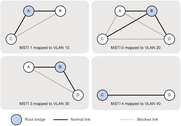
PVST configuration example
Network requirements
As shown in Figure 44, Device A and Device B work at the distribution layer, and Device C and Device D work at the access layer.
Configure PVST to meet the following requirements:
· Frames of a VLAN are forwarded along the spanning trees of the VLAN.
· VLAN 10, VLAN 20, and VLAN 30 are terminated on the distribution layer devices, and VLAN 40 is terminated on the access layer devices.
· The root bridge of VLAN 10 and VLAN 20 is Device A.
· The root bridge of VLAN 30 is Device B.
· The root bridge of VLAN 40 is Device C.
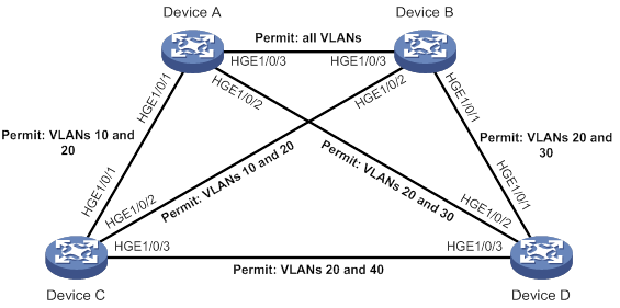
Configuration procedure
1. Configure VLANs and VLAN member ports. (Details not shown.)
? Create VLAN 10, VLAN 20, and VLAN 30 on both Device A and Device B.
? Create VLAN 10, VLAN 20, and VLAN 40 on Device C.
? Create VLAN 20, VLAN 30, and VLAN 40 on Device D.
? Configure the ports on these devices as trunk ports and assign them to related VLANs.
2. Configure Device A:
# Set the spanning tree mode to PVST.
<DeviceA> system-view
[DeviceA] stp mode pvst
# Configure the device as the root bridge of VLAN 10 and VLAN 20.
[DeviceA] stp vlan 10 20 root primary
# Enable the spanning tree feature globally and in VLAN 10, VLAN 20, and VLAN 30.
[DeviceA] stp global enable
[DeviceA] stp vlan 10 20 30 enable
3. Configure Device B:
# Set the spanning tree mode to PVST.
<DeviceB> system-view
[DeviceB] stp mode pvst
# Configure the device as the root bridge of VLAN 30.
[DeviceB] stp vlan 30 root primary
# Enable the spanning tree feature globally and in VLAN 10, VLAN 20, and VLAN 30.
[DeviceB] stp global enable
[DeviceB] stp vlan 10 20 30 enable
4. Configure Device C:
# Set the spanning tree mode to PVST.
<DeviceC> system-view
[DeviceC] stp mode pvst
# Configure the device as the root bridge of VLAN 40.
[DeviceC] stp vlan 40 root primary
# Enable the spanning tree feature globally and in VLAN 10, VLAN 20, and VLAN 40.
[DeviceC] stp global enable
[DeviceC] stp vlan 10 20 40 enable
5. Configure Device D:
# Set the spanning tree mode to PVST.
<DeviceD> system-view
[DeviceD] stp mode pvst
# Enable the spanning tree feature globally and in VLAN 20, VLAN 30, and VLAN 40.
[DeviceD] stp global enable
[DeviceD] stp vlan 20 30 40 enable
Verifying the configuration
When the network is stable, you can use the display stp brief command to display brief spanning tree information on each device.
# Display brief spanning tree information on Device A.
[DeviceA] display stp brief
VLAN ID Port Role STP State Protection
10 HundredGigE1/0/1 DESI FORWARDING NONE
10 HundredGigE1/0/3 DESI FORWARDING NONE
20 HundredGigE1/0/1 DESI FORWARDING NONE
20 HundredGigE1/0/2 DESI FORWARDING NONE
20 HundredGigE1/0/3 DESI FORWARDING NONE
30 HundredGigE1/0/2 DESI FORWARDING NONE
30 HundredGigE1/0/3 ROOT FORWARDING NONE
# Display brief spanning tree information on Device B.
[DeviceB] display stp brief
VLAN ID Port Role STP State Protection
10 HundredGigE1/0/2 DESI FORWARDING NONE
10 HundredGigE1/0/3 ROOT FORWARDING NONE
20 HundredGigE1/0/1 DESI FORWARDING NONE
20 HundredGigE1/0/2 DESI FORWARDING NONE
20 HundredGigE1/0/3 ROOT FORWARDING NONE
30 HundredGigE1/0/1 DESI FORWARDING NONE
30 HundredGigE1/0/3 DESI FORWARDING NONE
# Display brief spanning tree information on Device C.
[DeviceC] display stp brief
VLAN ID Port Role STP State Protection
10 HundredGigE1/0/1 ROOT FORWARDING NONE
10 HundredGigE1/0/2 ALTE DISCARDING NONE
20 HundredGigE1/0/1 ROOT FORWARDING NONE
20 HundredGigE1/0/2 ALTE DISCARDING NONE
20 HundredGigE1/0/3 DESI FORWARDING NONE
40 HundredGigE1/0/3 DESI FORWARDING NONE
# Display brief spanning tree information on Device D.
[DeviceD] display stp brief
VLAN ID Port Role STP State Protection
20 HundredGigE1/0/1 ALTE DISCARDING NONE
20 HundredGigE1/0/2 ROOT FORWARDING NONE
20 HundredGigE1/0/3 ALTE DISCARDING NONE
30 HundredGigE1/0/1 ROOT FORWARDING NONE
30 HundredGigE1/0/2 ALTE DISCARDING NONE
40 HundredGigE1/0/3 ROOT FORWARDING NONE
Based on the output, you can draw a topology for each VLAN spanning tree, as shown in Figure 45.
Figure 45 VLAN spanning tree topologies
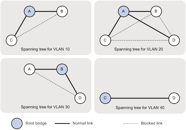
Configuring loop detection
Overview
Loop detection mechanism
The device detects loops by sending detection frames and then checking whether these frames return to any port on the device. If they do, the device considers that the port is on a looped link.
Loop detection usually works within a VLAN. If a detection frame is returned with a different VLAN tag than it was sent out with, an inter-VLAN loop has occurred. To remove the loop, examine the VLAN mapping configuration for incorrect settings. For more information about the VLAN mapping, see "Configuring VLAN mapping."
Figure 46 Ethernet frame header for loop detection
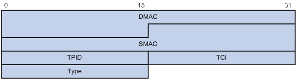
The Ethernet frame header for loop detection contains the following fields:
· DMAC—Destination MAC address of the frame, which is the multicast MAC address 010f-e200-0007. When a loop detection-enabled device receives a frame with this destination MAC address, it performs the following operations:
? Sends the frame to the CPU.
? Floods the frame in the VLAN from which the frame was originally received.
· SMAC—Source MAC address of the frame, which is the bridge MAC address of the sending device.
· TPID—Type of the VLAN tag, with the value of 0x8100.
· TCI—Information of the VLAN tag, including the priority and VLAN ID.
· Type—Protocol type, with the value of 0x8918.
Figure 47 Inner frame header for loop detection
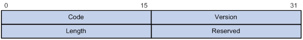
The inner frame header for loop detection contains the following fields:
· Code—Protocol sub-type, which is 0x0001, indicating the loop detection protocol.
· Version—Protocol version, which is always 0x0000.
· Length—Length of the frame. The value includes the inner header, but excludes the Ethernet header.
· Reserved—This field is reserved.
Frames for loop detection are encapsulated as TLV triplets.
Table 12 TLVs supported by loop detection
|
TLV |
Description |
Remarks |
|
End of PDU |
End of a PDU. |
Optional. |
|
Device ID |
Bridge MAC address of the sending device. |
Required. |
|
Port ID |
ID of the PDU sending port. |
Optional. |
|
Port Name |
Name of the PDU sending port. |
Optional. |
|
System Name |
Device name. |
Optional. |
|
Chassis ID |
Chassis ID of the sending port. |
Optional. |
|
Slot ID |
Slot ID of the sending port. |
Optional. |
|
Sub Slot ID |
Sub-slot ID of the sending port. |
Optional. |
Loop detection interval
Loop protection actions
When the device detects a loop on a port, it generates a log but performs no action on the port by default. You can configure the device to take one of the following actions:
· Block—Disables the port from learning MAC addresses and blocks the port.
· No-learning—Disables the port from learning MAC addresses.
· Shutdown—Shuts down the port to disable it from receiving and sending any frames.
Port status auto recovery
When the device configured with the block or no-learning loop action detects a loop on a port, it performs the action and waits three loop detection intervals. If the device does not receive a loop detection frame within three loop detection intervals, it performs the following operations:
· Automatically sets the port to the forwarding state.
· Notifies the user of the event.
When the device configured with the shutdown action detects a loop on a port, the following events occur:
1. The device automatically shuts down the port.
2. The device automatically sets the port to the forwarding state after the detection timer set by using the shutdown-interval command expires. For more information about the shutdown-interval command, see Fundamentals Command Reference.
3. The device shuts down the port again if a loop is still detected on the port when the detection timer expires.
This process is repeated until the loop is removed.
|
|
NOTE: Incorrect recovery can occur when loop detection frames are discarded to reduce the load. To avoid this, use the shutdown action, or manually remove the loop. |
Loop detection configuration task list
|
Tasks at a glance |
|
(Required.) Enabling loop detection |
|
(Optional.) Setting the loop protection action |
|
(Optional.) Setting the loop detection interval |
Enabling loop detection
You can enable loop detection globally or on a per-port basis. The global configuration applies to all ports in the specified VLANs. The per-port configuration applies to the individual port only when the port belongs to the specified VLANs. Per-port configurations take precedence over global configurations.
Enabling loop detection globally
|
Step |
Command |
Remarks |
|
1. Enter system view. |
system-view |
N/A |
|
2. Globally enable loop detection. |
loopback-detection global enable vlan { vlan-id--list | all } |
Disabled by default. |
Enabling loop detection on a port
|
Step |
Command |
Remarks |
|
1. Enter system view. |
system-view |
N/A |
|
2. Enter Layer 2 Ethernet interface view or Layer 2 aggregate interface view. |
interface interface-type interface-number |
N/A |
|
3. Enable loop detection on the port. |
loopback-detection enable vlan { vlan-id--list | all } |
Disabled by default. |
Setting the loop protection action
You can set the loop protection action globally or on a per-port basis. The global setting applies to all ports. The per-port setting applies to the individual ports. The per-port setting takes precedence over the global setting.
Setting the global loop protection action
|
Step |
Command |
Remarks |
|
1. Enter system view. |
system-view |
N/A |
|
2. Set the global loop protection action. |
loopback-detection global action shutdown |
By default, the device generates a log but performs no action on the port on which a loop is detected. |
Setting the loop protection action on a Layer 2 Ethernet interface
|
Step |
Command |
Remarks |
|
1. Enter system view. |
system-view |
N/A |
|
2. Enter Layer 2 Ethernet interface view. |
interface interface-type interface-number |
N/A |
|
3. Set the loop protection action on the interface. |
loopback-detection action { block | no-learning | shutdown } |
By default, the device generates a log but performs no action on the port on which a loop is detected. |
Setting the loop protection action on a Layer 2 aggregate interface
|
Step |
Command |
Remarks |
|
1. Enter system view. |
system-view |
N/A |
|
2. Enter Layer 2 aggregate interface view. |
interface interface-type interface-number |
N/A |
|
3. Set the loop protection action on the interface. |
loopback-detection action shutdown |
By default, the device generates a log but performs no action on the port on which a loop is detected. |
Setting the loop detection interval
With loop detection enabled, the device sends loop detection frames at the loopback detection interval. A shorter interval offers more sensitive detection but consumes more resources. Consider the system performance and loop detection speed when you set the loop detection interval.
To set the loop detection interval:
|
Step |
Command |
Remarks |
|
1. Enter system view. |
system-view |
N/A |
|
2. Set the loop detection interval. |
loopback-detection interval-time interval |
The default setting is 30 seconds. |
Displaying and maintaining loop detection
Execute display commands in any view.
|
Task |
Command |
|
Display the loop detection configuration and status. |
display loopback-detection |
Loop detection configuration example
Network requirements
As shown in Figure 48, configure loop detection on Device A to meet the following requirements:
· Device A generates a log as a notification.
· Device A automatically shuts down the port on which a loop is detected.
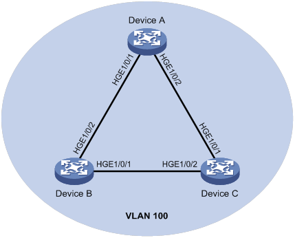
Configuration procedure
1. Configure Device A:
# Create VLAN 100, and globally enable loop detection for the VLAN.
<DeviceA> system-view
[DeviceA] vlan 100
[DeviceA-vlan100] quit
[DeviceA] loopback-detection global enable vlan 100
# Configure HundredGigE 1/0/1 and HundredGigE 1/0/2 as trunk ports, and assign them to VLAN 100.
[DeviceA] interface HundredGigE 1/0/1
[DeviceA-HundredGigE1/0/1] port link-type trunk
[DeviceA-HundredGigE1/0/1] port trunk permit vlan 100
[DeviceA-HundredGigE1/0/1] quit
[DeviceA] interface hundredgige 1/0/2
[DeviceA-HundredGigE1/0/2] port link-type trunk
[DeviceA-HundredGigE1/0/2] port trunk permit vlan 100
[DeviceA-HundredGigE1/0/2] quit
# Set the global loop protection action to shutdown.
[DeviceA] loopback-detection global action shutdown
# Set the loop detection interval to 35 seconds.
[DeviceA] loopback-detection interval-time 35
2. Configure Device B:
# Create VLAN 100.
<DeviceB> system-view
[DeviceB] vlan 100
[DeviceB–vlan100] quit
# Configure HundredGigE 1/0/1 and HundredGigE 1/0/2 as trunk ports, and assign them to VLAN 100.
[DeviceB] interface hundredgige 1/0/1
[DeviceB-HundredGigE1/0/1] port link-type trunk
[DeviceB-HundredGigE1/0/1] port trunk permit vlan 100
[DeviceB-HundredGigE1/0/1] quit
[DeviceB] interface hundredgige 1/0/2
[DeviceB-HundredGigE1/0/2] port link-type trunk
[DeviceB-HundredGigE1/0/2] port trunk permit vlan 100
[DeviceB-HundredGigE1/0/2] quit
3. Configure Device C:
# Create VLAN 100.
<DeviceC> system-view
[DeviceC] vlan 100
[DeviceC–vlan100] quit
# Configure HundredGigE 1/0/1 and HundredGigE 1/0/2 as trunk ports, and assign them to VLAN 100.
[DeviceC] interface hundredgige 1/0/1
[DeviceC-HundredGigE1/0/1] port link-type trunk
[DeviceC-HundredGigE1/0/1] port trunk permit vlan 100
[DeviceC-HundredGigE1/0/1] quit
[DeviceC] interface hundredgige 1/0/2
[DeviceC-HundredGigE1/0/2] port link-type trunk
[DeviceC-HundredGigE1/0/2] port trunk permit vlan 100
[DeviceC-HundredGigE1/0/2] quit
Verifying the configuration
# View the system logs on devices, for example, Device A.
[DeviceA]
%Feb 24 15:04:29:663 2013 DeviceA LPDT/4/LPDT LOOPED: Loopback exists on HundredGigE1/0/1.
%Feb 24 15:04:29:667 2013 DeviceA LPDT/4/LPDT LOOPED: Loopback exists on HundredGigE1/0/2.
%Feb 24 15:04:44:243 2013 DeviceA LPDT/5/LPDT RECOVERED: Loopback on HundredGigE1/0/1 recovered.
%Feb 24 15:04:44:248 2013 DeviceA LPDT/5/LPDT RECOVERED: Loopback on HundredGigE1/0/2 recovered.
The output shows the following information:
· Device A detected loops on HundredGigE 1/0/1 and HundredGigE 1/0/2 within a loop detection interval.
· Loops on HundredGigE 1/0/1 and HundredGigE 1/0/2 were removed.
# Use the display loopback-detection command to display the loop detection configuration and status on devices, for example, Device A.
[DeviceA] display loopback-detection
Loop detection is enabled.
Loop detection interval is 35 second(s).
No loopback is detected.
The output shows that the device has removed the loops from HundredGigE 1/0/1 and HundredGigE 1/0/2 according to the shutdown action.
# Display the status of HundredGigE 1/0/1 on devices, for example, Device A.
[DeviceA] display interface hundredgige 1/0/1
HundredGigE1/0/1 current state: DOWN (Loop detection down)
...
The output shows that HundredGigE 1/0/1 is already shut down by the loop detection module.
# Display the status of HundredGigE 1/0/2 on devices, for example, Device A.
[DeviceA] display interface hundredgige 1/0/2
HundredGigE1/0/2 current state: DOWN (Loop detection down)
...
The output shows that HundredGigE 1/0/2 is already shut down by the loop detection module.
Configuring VLANs
Overview
Ethernet is a family of shared-media LAN technologies based on the CSMA/CD mechanism. An Ethernet LAN is both a collision domain and a broadcast domain. Because the medium is shared, collisions and broadcasts are common in an Ethernet LAN. Typically, bridges and Layer 2 switches can reduce collisions in an Ethernet LAN. To confine broadcasts, a Layer 2 switch must use the Virtual Local Area Network (VLAN) technology.
VLANs enable a Layer 2 switch to break a LAN down into smaller broadcast domains, as shown in Figure 49.
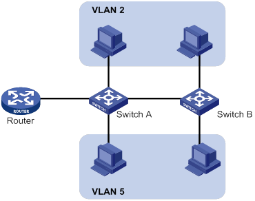
A VLAN is logically divided on an organizational basis rather than on a physical basis. For example, you can assign all workstations and servers used by a particular workgroup to the same VLAN, regardless of their physical locations. Hosts in the same VLAN can directly communicate with one another. You need a router or a Layer 3 switch for hosts in different VLANs to communicate with one another.
All these VLAN features reduce bandwidth waste, improve LAN security, and enable flexible virtual group creation.
VLAN frame encapsulation
To identify Ethernet frames from different VLANs, IEEE 802.1Q inserts a four-byte VLAN tag between the destination and source MAC address (DA&SA) field and the Type field.
Figure 50 VLAN tag placement and format
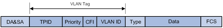
A VLAN tag includes the following fields:
· TPID—16-bit tag protocol identifier that indicates whether a frame is VLAN-tagged. By default, the hexadecimal TPID value 8100 identifies a VLAN-tagged frame. A device vendor can set the TPID to a different value. For compatibility with a neighbor device, set the TPID value on the device to be the same as the neighbor device.
· Priority—3-bit long, identifies the 802.1p priority of the frame. For more information, see ACL and QoS Configuration Guide.
· CFI—1-bit long canonical format indicator that indicates whether the MAC addresses are encapsulated in the standard format when packets are transmitted across different media. Available values include:
? 0 (default)—The MAC addresses are encapsulated in the standard format.
? 1—The MAC addresses are encapsulated in a non-standard format.
This field is always set to 0 for Ethernet.
· VLAN ID—12-bit long, identifies the VLAN to which the frame belongs. The VLAN ID range is 0 to 4095. VLAN IDs 0 and 4095 are reserved, and VLAN IDs 1 to 4094 are user configurable.
The way a network device handles an incoming frame depends on whether the frame has a VLAN tag and the value of the VLAN tag (if any). For more information, see "Introduction."
Ethernet supports encapsulation formats Ethernet II, 802.3/802.2 LLC, 802.3/802.2 SNAP, and 802.3 raw. The Ethernet II encapsulation format is used here. For information about the VLAN tag fields in other frame encapsulation formats, see related protocols and standards.
For a frame that has multiple VLAN tags, the device handles it according to its outermost VLAN tag and transmits its inner VLAN tags as the payload.
Protocols and standards
IEEE 802.1Q, IEEE Standard for Local and Metropolitan Area Networks: Virtual Bridged Local Area Networks
Configuring basic VLAN settings
|
Step |
Command |
Remarks |
|
1. Enter system view. |
system-view |
N/A |
|
2. (Optional.) Create a VLAN and enter its view, or create a list of VLANs. |
vlan { vlan-id1 [ to vlan-id2 ] | all } |
By default, only the system default VLAN (VLAN 1) exists. |
|
3. Enter VLAN view. |
vlan vlan-id |
To configure a VLAN after you create a list of VLANs, you must perform this step. |
|
4. Set a name for the VLAN. |
name text |
By default, the name of a VLAN is VLAN vlan-id. The vlan-id argument specifies the VLAN ID in a four-digit format. If the VLAN ID has fewer than four digits, leading zeros are added. For example, the name of VLAN 100 is VLAN 0100. |
|
5. Configure the description for the VLAN. |
description text |
By default, the description of a VLAN is VLAN vlan-id. The vlan-id argument specifies the VLAN ID in a four-digit format. If the VLAN ID has fewer than four digits, leading zeros are added. For example, the default description of VLAN 100 is VLAN 0100. |
|
|
NOTE: · As the system default VLAN, VLAN 1 cannot be created or deleted. · Before you delete a dynamic VLAN or a VLAN locked by an application, you must first remove the configuration from the VLAN. |
Configuring VLAN interfaces
Hosts of different VLANs use VLAN interfaces to communicate at Layer 3. VLAN interfaces are virtual interfaces that do not exist as physical entities on devices. For each VLAN, you can create one VLAN interface and assign an IP address to it. The VLAN interface acts as the gateway of the VLAN to forward packets destined for another IP subnet at Layer 3.
Before you create a VLAN interface for a VLAN, create the VLAN first.
To configure basic settings of a VLAN interface:
|
Step |
Command |
Remarks |
|
1. Enter system view. |
system-view |
N/A |
|
2. Create a VLAN interface and enter its view. |
interface vlan-interface interface-number |
If the VLAN interface already exists, you enter its view directly. By default, no VLAN interfaces exist. |
|
3. Assign an IP address to the VLAN interface. |
ip address ip-address { mask | mask-length } [ sub ] |
By default, no IP address is assigned to a VLAN interface. |
|
4. Configure the description for the VLAN interface. |
description text |
The default setting is the VLAN interface name. For example, Vlan-interface1 Interface. |
|
5. (Optional.) Specify a traffic processing slot for the VLAN interface. |
In standalone mode: In IRF mode: |
By default, no traffic processing slot is specified for the VLAN interface. Traffic on a VLAN interface is processed on the slot at which the traffic arrives. |
|
6. Set the MTU for the VLAN interface. |
mtu size |
The default setting is 1500 bytes. |
|
7. Set a MAC address for the VLAN interface. |
mac-address mac-address |
By default, the MAC address of a VLAN interface is not configured. |
|
8. Set the expected bandwidth for the interface. |
bandwidth bandwidth-value |
By default, the expected bandwidth (in kbps) is the interface baud rate divided by 1000. |
|
9. (Optional.) Restore the default settings for the VLAN interface. |
default |
N/A |
|
10. (Optional.) Bring up the VLAN interface. |
undo shutdown |
N/A |
Configuring port-based VLANs
Introduction
Port-based VLANs group VLAN members by port. A port forwards packets from a VLAN only after it is assigned to the VLAN.
Port link type
You can set the link type of a port to access, trunk, or hybrid. The port link type determines whether the port can be assigned to multiple VLANs. The link types use the following VLAN tag handling methods:
· Access—An access port can forward packets only from one VLAN and send these packets untagged. An access port is typically used in the following conditions:
? Connecting to a terminal device that does not support VLAN packets.
? In scenarios that do not distinguish VLANs.
· Trunk—A trunk port can forward packets from multiple VLANs. Except packets from the port VLAN ID (PVID), packets sent out of a trunk port are VLAN-tagged. Ports connecting network devices are typically configured as trunk ports.
· Hybrid—A hybrid port can forward packets from multiple VLANs. The tagging status of the packets forwarded by a hybrid port depends on the port configuration. In one-to-two VLAN mapping, hybrid ports are used to remove SVLAN tags for downlink traffic. For more information about one-to-two VLAN mapping, see "Configuring VLAN mapping."
PVID
The PVID identifies the default VLAN of a port. Untagged packets received on a port are considered as the packets from the port PVID.
When you set the PVID for a port, follow these restrictions and guidelines:
· An access port can join only one VLAN. The VLAN to which the access port belongs is the PVID of the port.
· A trunk or hybrid port supports multiple VLANs and the PVID configuration.
· When you use the undo vlan command to delete the PVID of a port, either of the following events occurs depending on the port link type:
? For an access port, the PVID of the port changes to VLAN 1.
? For a hybrid or trunk port, the PVID setting of the port does not change.
You can use a nonexistent VLAN as the PVID for a hybrid or trunk port, but not for an access port.
· As a best practice, set the same PVID for a local port and its peer.
· To prevent a port from dropping untagged packets or PVID-tagged packets, assign the port to its PVID.
How ports of different link types handle frames
|
Actions |
Access |
Trunk |
Hybrid |
|
|
In the inbound direction for an untagged frame |
Tags the frame with the PVID tag. |
· If the PVID is permitted on the port, tags the frame with the PVID tag. · If not, drops the frame. |
||
|
In the inbound direction for a tagged frame |
· Receives the frame if its VLAN ID is the same as the PVID. · Drops the frame if its VLAN ID is different from the PVID. |
· Receives the frame if its VLAN is permitted on the port. · Drops the frame if its VLAN is not permitted on the port. |
||
|
In the outbound direction |
Removes the VLAN tag and sends the frame. |
· Removes the tag and sends the frame if the frame carries the PVID tag and the port belongs to the PVID. · Sends the frame without removing the tag if its VLAN is carried on the port but is different from the PVID. |
Sends the frame if its VLAN is permitted on the port. The tagging status of the frame depends on the port hybrid vlan command configuration. |
|
Assigning an access port to a VLAN
You can assign an access port to a VLAN in VLAN view or interface view.
Make sure the VLAN has been created.
Assign one or multiple access ports to a VLAN in VLAN view
|
Step |
Command |
Remarks |
|
1. Enter system view. |
system-view |
N/A |
|
2. Enter VLAN view. |
vlan vlan-id |
N/A |
|
3. Assign one or multiple access ports to the VLAN. |
port interface-list |
By default, all ports belong to VLAN 1. |
Assign an access port to a VLAN in interface view
|
Step |
Command |
Remarks |
|
1. Enter system view. |
system-view |
N/A |
|
2. Enter interface view. |
·
Enter Layer 2 Ethernet interface view: ·
Enter Layer 2 aggregate interface view: |
N/A |
|
3. Set the port link type to access. |
port link-type access |
By default, all ports are access ports. |
|
4. (Optional.) Assign the access port to a VLAN. |
port access vlan vlan-id |
By default, all access ports belong to VLAN 1. |
Assigning a trunk port to a VLAN
A trunk port supports multiple VLANs. You can assign it to a VLAN in interface view.
When you assign a trunk port to a VLAN, follow these restrictions and guidelines:
· To change the link type of a port from trunk to hybrid, set the link type to access first.
· To enable a trunk port to transmit packets from its PVID, you must assign the trunk port to the PVID by using the port trunk permit vlan command.
To assign a trunk port to one or multiple VLANs:
|
Step |
Command |
Remarks |
|
1. Enter system view. |
system-view |
N/A |
|
2. Enter interface view. |
·
Enter Layer 2 Ethernet interface view: ·
Enter Layer 2 aggregate interface view: |
N/A |
|
3. Set the port link type to trunk. |
port link-type trunk |
By default, all ports are access ports. |
|
4. Assign the trunk port to the specified VLANs. |
port trunk permit vlan { vlan-id-list | all } |
By default, a trunk port permits only VLAN 1. |
|
5. (Optional.) Set the PVID for the trunk port. |
port trunk pvid vlan vlan-id |
The default setting is VLAN 1. |
Assigning a hybrid port to a VLAN
A hybrid port supports multiple VLANs. You can assign it to the specified VLANs in interface view. Make sure the VLANs have been created.
When you assign a hybrid port to a VLAN, follow these restrictions and guidelines:
· To change the link type of a port from trunk to hybrid, set the link type to access first.
· To enable a hybrid port to transmit packets from its PVID, you must assign the hybrid port to the PVID by using the port hybrid vlan command.
To assign a hybrid port to one or multiple VLANs:
|
Step |
Command |
Remarks |
|
1. Enter system view. |
system-view |
N/A |
|
2. Enter interface view. |
·
Enter Layer 2 Ethernet interface view: ·
Enter Layer 2 aggregate interface view: |
N/A |
|
3. Set the port link type to hybrid. |
port link-type hybrid |
By default, all ports are access ports. |
|
4. Assign the hybrid port to the specified VLANs. |
port hybrid vlan vlan-id-list { tagged | untagged } |
By default, the hybrid port is an untagged member of the VLAN to which the port belongs when its link type is access. |
|
5. (Optional.) Set the PVID for the hybrid port. |
port hybrid pvid vlan vlan-id |
By default, the PVID of a hybrid port is the ID of the VLAN to which the port belongs when its link type is access. |
Displaying and maintaining VLANs
Execute display commands in any view and reset commands in user view.
|
Task |
Command |
|
Display VLAN interface information. |
display interface vlan-interface [ interface-number ] [ brief [ description | down ] ] |
|
Display VLAN information. |
display vlan [ vlan-id1 [ to vlan-id2 ] | all | dynamic | reserved | static ] |
|
Display brief VLAN information. |
display vlan brief |
|
Display hybrid ports or trunk ports on the device. |
display port { hybrid | trunk } |
|
Clear statistics on a port. |
reset counters interface vlan-interface [ interface-number ] |
Port-based VLAN configuration example
Network requirements
As shown in Figure 51:
· Host A and Host C belong to Department A. VLAN 100 is assigned to Department A.
· Host B and Host D belong to Department B. VLAN 200 is assigned to Department B.
Configure port-based VLANs so that only hosts in the same department can communicate with each other.
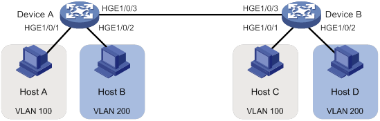
Configuration procedure
1. Configure Device A:
# Create VLAN 100, and assign HundredGigE 1/0/1 to VLAN 100.
<DeviceA> system-view
[DeviceA] vlan 100
[DeviceA-vlan100] port hundredgige 1/0/1
[DeviceA-vlan100] quit
# Create VLAN 200, and assign HundredGigE 1/0/2 to VLAN 200.
[DeviceA] vlan 200
[DeviceA-vlan200] port hundredgige 1/0/2
[DeviceA-vlan200] quit
# Configure HundredGigE 1/0/3 as a trunk port, and assign the port to VLANs 100 and 200.
[DeviceA] interface hundredgige 1/0/3
[DeviceA-HundredGigE1/0/3] port link-type trunk
[DeviceA-HundredGigE1/0/3] port trunk permit vlan 100 200
Please wait... Done.
2. Configure Device B in the same way Device A is configured. (Details not shown.)
3. Configure hosts:
a. Configure Host A and Host C to be on the same IP subnet. For example, 192.168.100.0/24.
b. Configure Host B and Host D to be on the same IP subnet. For example, 192.168.200.0/24.
Verifying the configuration
# Verify that Host A and Host C can ping each other, but they both fail to ping Host B and Host D. (Details not shown.)
# Verify that Host B and Host D can ping each other, but they both fail to ping Host A and Host C. (Details not shown.)
# Verify that VLANs 100 and 200 are correctly configured on Device A.
[DeviceA-HundredGigE1/0/3] display vlan 100
VLAN ID: 100
VLAN type: Static
Route interface: Not configured
Description: VLAN 0100
Name: VLAN 0100
Tagged ports:
HundredGigE1/0/3
Untagged ports:
HundredGigE1/0/1
[DeviceA-HundredGigE1/0/3] display vlan 200
VLAN ID: 200
VLAN type: Static
Route interface: Not configured
Description: VLAN 0200
Name: VLAN 0200
Tagged ports:
HundredGigE1/0/3
Untagged ports:
HundredGigE1/0/2
Configuring VLAN mapping
Overview
VLAN mapping re-marks VLAN tagged traffic with new VLAN IDs. H3C provides the following types of VLAN mapping:
· One-to-one VLAN mapping—Replaces one VLAN tag with another.
· One-to-two VLAN mapping—Tags single-tagged packets with an outer VLAN tag.
· Zero-to-two VLAN mapping—Adds double VLAN tags to untagged packets.
· Two-to-two VLAN mapping—Replaces the outer and inner VLAN IDs of double tagged traffic with a new pair of VLAN IDs.
· Two-to-three VLAN mapping—Adds an outermost VLAN tag to double-tagged packets.
VLAN mapping application scenarios
One-to-one VLAN mapping
Figure 52 shows a typical application scenario of one-to-one VLAN mapping. The scenario implements broadband Internet access for a community.
Figure 52 Application scenario of one-to-one VLAN mapping
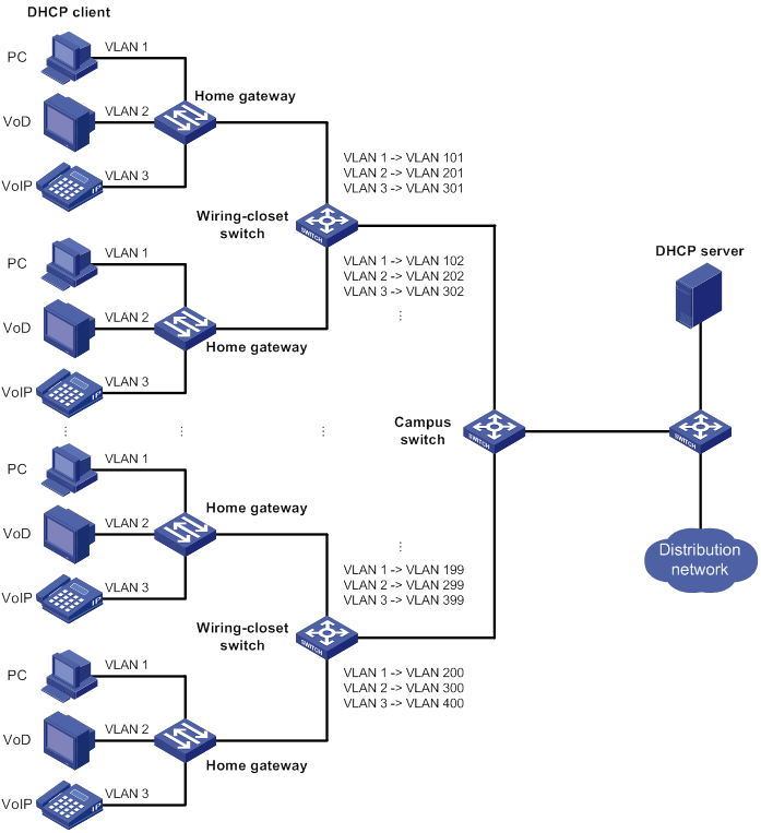
As shown in Figure 52, the network is implemented as follows:
· Each home gateway uses different VLANs to transmit the PC, VoD, and VoIP services.
· To further subclassify each type of traffic by customer, configure one-to-one VLAN mapping on the wiring-closet switches. This feature assigns a separate VLAN to each type of traffic from each customer. The required total number of VLANs in the network can be very large.
One-to-two and two-to-two VLAN mapping
Figure 53 shows a typical application scenario of one-to-two and two-to-two VLAN mapping. In this scenario, the two remote sites of the same VPN must communicate across two SP networks.
Figure 53 Application scenario of one-to-two and two-to-two VLAN mapping
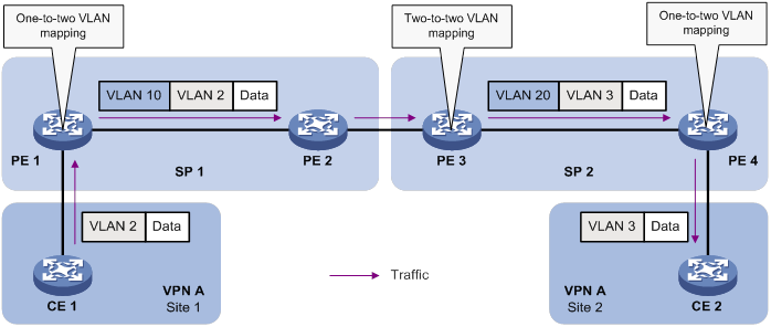
Site 1 and Site 2 are in VLAN 2 and VLAN 3, respectively. The SP 1 network assigns SVLAN 10 to Site 1. The SP 2 network assigns SVLAN 20 to Site 2. When the packet from Site 1 arrives at PE 1, PE 1 tags the packet with SVLAN 10 by using one-to-two VLAN mapping.
When the double-tagged packet from the SP 1 network arrives at the SP 2 network interface, PE 3 processes the packet as follows:
· Replaces SVLAN tag 10 with SVLAN tag 20.
· Replaces CVLAN tag 2 with CVLAN tag 3.
One-to-two VLAN mapping provides the following benefits:
· Enables a customer network to plan its CVLAN assignment without conflicting with SVLANs.
· Adds a VLAN tag to a tagged packet and expands the number of available VLANs to 4094 × 4094.
· Reduces the stress on the SVLAN resources, which were 4094 VLANs in the SP network before the mapping process was initiated.
Zero-to-two VLAN mapping
The application scenario of zero-to-two VLAN mapping is similar to the scenario of one-to-two VLAN mapping. Zero-to-two VLAN mapping is used on the customer-side port of a PE to add double tags to untagged packets.
Two-to-three VLAN mapping
The application scenario of two-to-three VLAN mapping is similar to the scenario of one-to-two VLAN mapping. Two-to-three VLAN mapping is used on the customer-side port of a PE to add an outermost VLAN tag to double-tagged packets.
VLAN mapping implementations
Figure 54 shows a simplified network that illustrates basic VLAN mapping terms.
Basic VLAN mapping terms include the following:
· Uplink traffic—Traffic transmitted from the customer network to the service provider network.
· Downlink traffic—Traffic transmitted from the service provider network to the customer network.
· Network-side port—A port connected to or closer to the service provider network.
· Customer-side port—A port connected to or closer to the customer network.
Figure 54 Basic VLAN mapping terms
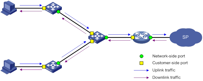
One-to-one VLAN mapping
As shown in Figure 55, one-to-one VLAN mapping is implemented on the customer-side port and replaces VLAN tags as follows:
· Replaces the CVLAN with the SVLAN for the uplink traffic.
· Replaces the SVLAN with the CVLAN for the downlink traffic.
Figure 55 One-to-one VLAN mapping implementation
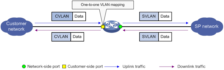
One-to-two VLAN mapping
As shown in Figure 56, one-to-two VLAN mapping is implemented on the customer-side port to add the SVLAN tag for the uplink traffic.
For the downlink traffic to be correctly sent to the customer network, make sure the SVLAN tag is removed on the customer-side port before transmission. Use one of the following methods to remove the SVLAN tag from the downlink traffic:
· Configure the customer-side port as a hybrid port and assign the port to the SVLAN as an untagged member.
· Configure the customer-side port as a trunk port and set the port PVID to the SVLAN.
Figure 56 One-to-two VLAN mapping implementation
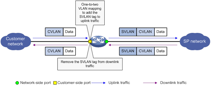
Zero-to-two VLAN mapping
As shown in Figure 57, zero-to-two VLAN mapping is implemented on the customer-side port and processes VLAN tags as follows:
· Adds double tags to untagged uplink traffic.
· Removes SVLAN tags and CVLAN tags from downlink traffic.
To ensure correct transmission of downlink traffic, use one of the following methods to sustain the SVLAN tag in the downlink traffic:
· Configure the customer-side port as a trunk port and assign it to the SVLAN. Make sure the SVLAN is not the PVID.
· Configure the customer-side port as a hybrid port and assign it to the SVLAN as a tagged member.
Figure 57 Zero-to-two VLAN mapping implementation
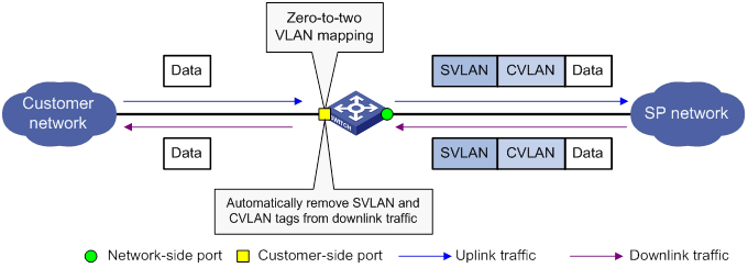
Two-to-two VLAN mapping
As shown in Figure 58, two-to-two VLAN mapping is implemented on the customer-side port and replaces VLAN tags as follows:
· Replaces the CVLAN and the SVLAN with the CVLAN' and the SVLAN' for the uplink traffic.
· Replaces the SVLAN' and CVLAN' with the SVLAN and the CVLAN for the downlink traffic.
Figure 58 Two-to-two VLAN mapping implementation
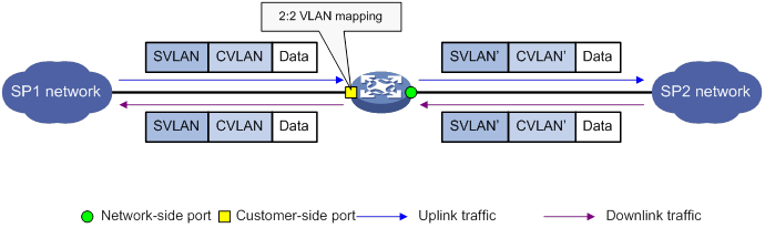
Two-to-three VLAN mapping
As shown in Figure 59, two-to-three VLAN mapping is implemented on the customer-side port to add an outermost VLAN tag to double-tagged uplink traffic.
For the downlink traffic to be correctly sent to the customer network, use one of the following methods to remove the outermost tag from the traffic:
· Configure the customer-side port as a trunk port, configure the outermost VLAN as the PVID, and assign the port to the PVID.
· Configure the customer-side port as a hybrid port and assign the port to the outermost VLAN as an untagged member.
Figure 59 Two-to-three VLAN mapping implementation
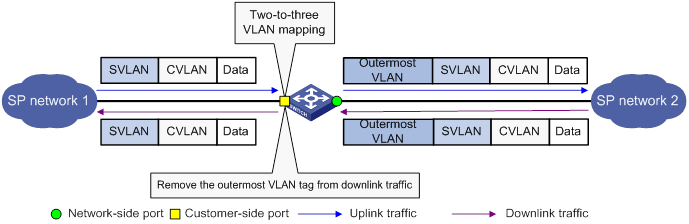
VLAN mapping configuration task list
To add or replace VLAN tags for packets, you can configure both VLAN mapping and a QoS policy. The QoS policy takes effect if a configuration conflict occurs. For information about QoS policies, see ACL and QoS Configuration Guide.
|
|
IMPORTANT: Use the appropriate VLAN mapping methods for the devices in the network. |
To configure VLAN mapping:
|
Tasks at a glance |
Remarks |
|
Configure one-to-one VLAN mapping on the wiring-closet switch, as shown in Figure 52. |
|
|
Configure one-to-two VLAN mapping on PE 1 and PE 4, as shown in Figure 53, through which traffic from customer networks enters the service provider networks. |
|
|
N/A |
|
|
Configure two-to-two VLAN mapping on PE 3, as shown in Figure 53, which is an edge device of the SP 2 network. |
|
|
N/A |
Configuring one-to-one VLAN mapping
Configure one-to-one VLAN mapping on the customer-side ports of wiring-closet switches (see Figure 52) to isolate traffic of the same service type from different homes.
Before you configure one-to-one VLAN mapping, create the original VLAN and the translated VLAN.
To configure one-to-one VLAN mapping:
|
Step |
Command |
Remarks |
|
1. Enter system view. |
system-view |
N/A |
|
2. Enter Layer 2 Ethernet interface view or Layer 2 aggregate interface view. |
·
Enter Layer 2 Ethernet interface view: ·
Enter Layer 2 aggregate interface view: |
N/A |
|
3. Set the link type of the port. |
·
Set the port link type to trunk: ·
Set the port link type to hybrid: |
By default, the link type of a port is access. |
|
4. Assign the port to the original VLANs and the translated VLANs. |
·
For the trunk
port: ·
For the hybrid
port: |
N/A |
|
5. Configure a one-to-one VLAN mapping. |
vlan mapping vlan-id translated-vlan vlan-id |
By default, no VLAN mapping is configured on an interface. |
Configuring one-to-two VLAN mapping
Configure one-to-two VLAN mapping on the customer-side ports of edge devices from which customer traffic enters SP networks, for example, on PEs 1 and 4 in Figure 53. One-to-two VLAN mapping enables the edge devices to add an SVLAN tag to each incoming packet.
Before you configure one-to-two VLAN mapping, create the CVLAN and the SVLAN.
The MTU of an interface is 1500 bytes by default. After a VLAN tag is added to a packet, the packet length is added by 4 bytes. As a best practice, set the MTU to a minimum of 1504 bytes for ports on the forwarding path of the packet in the service provider network.
To configure one-to-two VLAN mapping:
|
Step |
Command |
Remarks |
|
1. Enter system view. |
system-view |
N/A |
|
2. Enter Layer 2 Ethernet interface view or Layer 2 aggregate interface view. |
·
Enter Layer 2 Ethernet interface view: ·
Enter Layer 2 aggregate interface view: |
N/A |
|
3. Set the link type of the port. |
·
Set the port link type to trunk: ·
Set the port link type to hybrid: |
By default, the link type of a port is access. |
|
4. Assign the port to the CVLANs. |
·
For the trunk port: ·
For the hybrid port: |
N/A |
|
5. Configure the port to allow packets from the SVLAN to pass through untagged. |
· For the trunk port: a.
Configure the SVLAN as the PVID of
the trunk port: b.
Assign the trunk
port to the SVLAN: ·
For the hybrid port: |
N/A |
|
6. Configure a one-to-two VLAN mapping. |
vlan mapping nest { range vlan-range-list | single vlan-id-list } nested-vlan vlan-id |
By default, no VLAN mapping is configured on an interface. Only one SVLAN tag can be added to packets from the same CVLAN. To add different SVLAN tags to different CVLAN packets, set the port link type to hybrid and repeat this command. |
Configuring zero-to-two VLAN mapping
As a best practice, set the MTU to a minimum of 1504 bytes for ports on the forwarding path of the double-tagged packet in the service provider network.
To configure zero-to-two VLAN mapping:
|
Step |
Command |
Remarks |
|
1. Enter system view. |
system-view |
N/A |
|
2. Enter Layer 2 Ethernet interface view or Layer 2 aggregate interface view. |
·
Enter Layer 2 Ethernet interface view: ·
Enter Layer 2 aggregate interface view: |
N/A |
|
3. Set the port link type. |
·
Set the port link type to trunk: ·
Set the port link type to hybrid: |
By default, the link type of a port is access. |
|
4. Assign the port to the SVLAN. |
·
Assign the trunk port to the SVLAN: ·
Assign the hybrid port to the SVLAN as a
tagged member: |
Do not configure the SVLAN as the PVID of the trunk port. |
|
5. Configure a zero-to-two VLAN mapping. |
vlan mapping untagged nested-outer-vlan outer-vlan-id nested-inner-vlan inner-vlan-id |
By default, no VLAN mapping is configured on an interface. |
Configuring two-to-two VLAN mapping
Configure two-to-two VLAN mapping on the customer-side port of an edge device that connects two SP networks, for example, on PE 3 in Figure 53. Two-to-two VLAN mapping enables two sites in different VLANs to communicate at Layer 2 across two service provider networks that use different VLAN assignment schemes.
Before you configure two-to-two VLAN mapping, create the original VLANs and the translated VLANs.
To configure two-to-two VLAN mapping:
|
Step |
Command |
Remarks |
|
1. Enter system view. |
system-view |
N/A |
|
2. Enter Layer 2 Ethernet interface view or Layer 2 aggregate interface view. |
·
Enter Layer 2 Ethernet interface view: ·
Enter Layer 2 aggregate interface view: |
N/A |
|
3. Set the link type of the port. |
·
Set the port link type to trunk: ·
Set the port link type to hybrid: |
By default, the link type of a port is access. |
|
4. Assign the port to the original VLANs and the translated VLANs. |
·
For the trunk port: ·
For the hybrid port: |
N/A |
|
5. Configure a two-to-two VLAN mapping. |
vlan mapping tunnel outer-vlan-id inner-vlan-id translated-vlan outer-vlan-id inner-vlan-id |
By default, no VLAN mapping is configured on an interface. |
Configuring two-to-three VLAN mapping
As a best practice, set the MTU to a minimum of 1508 bytes for ports on the forwarding path of the triple-tagged packet in the service provider network.
To configure two-to-three VLAN mapping:
|
Step |
Command |
Remarks |
|
1. Enter system view. |
system-view |
N/A |
|
2. Enter Layer 2 Ethernet interface view or Layer 2 aggregate interface view. |
·
Enter Layer 2 Ethernet interface view: ·
Enter Layer 2 aggregate interface view: |
N/A |
|
3. Set the link type of the port. |
·
Set the port link type to trunk: ·
Set the port link type to hybrid: |
By default, the link type of a port is access. |
|
4. Assign the port to the original SVLAN. |
·
For the trunk port: ·
For the hybrid port: |
By default, a trunk port is assigned only to VLAN 1, and a hybrid port is an untagged member of VLAN 1. |
|
5. Configure the port to allow the packets from the outermost VLAN to pass through untagged. |
· For the trunk port: a.
Configure the outermost VLAN as the PVID
of the trunk port: b.
Assign the port to the PVID: ·
For the hybrid port: |
N/A |
|
6. Configure a two-to-three VLAN mapping. |
vlan mapping double-tagged { outer-vlan outer-vlan-id inner-vlan inner-vlan-id | outer-vlan-range vlan-id-list inner-vlan inner-vlan-id | outer-vlan outer-vlan-id inner-vlan-range vlan-id-list } nested-vlan nested-vlan |
By default, no VLAN mapping is configured on an interface. |
Displaying and maintaining VLAN mapping
Execute display commands in any view.
|
Task |
Command |
|
Display VLAN mapping information. |
display vlan mapping [ interface interface-type interface-number ] |
VLAN mapping configuration examples
One-to-one VLAN mapping configuration example
Network requirements
As shown in Figure 60:
· Each household subscribes to PC, VoD, and VoIP services, and obtains the IP address through DHCP.
· On the home gateways, VLANs 1, 2, and 3 are assigned to PC, VoD, and VoIP traffic, respectively.
To isolate traffic of the same service type from different households, configure one-to-one VLAN mappings on the wiring-closet switches. This feature assigns one VLAN to each type of traffic from each household.
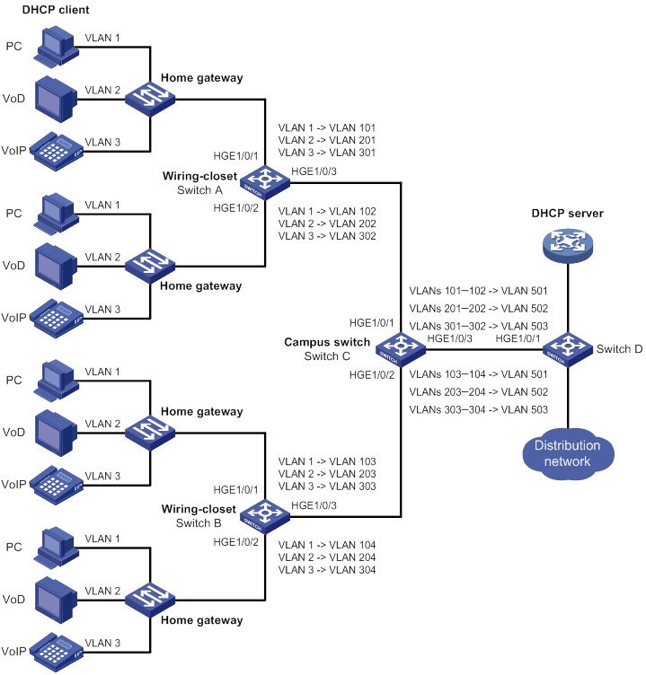
Configuration procedure
1. Configure Switch A:
# Create the original VLANs.
<SwitchA> system-view
[SwitchA] vlan 2 to 3
# Create the translated VLANs.
[SwitchA] vlan 101 to 102
[SwitchA] vlan 201 to 202
[SwitchA] vlan 301 to 302
# Configure customer-side port HundredGigE 1/0/1 as a trunk port.
<SwitchA> system-view
[SwitchA] interface hundredgige 1/0/1
[SwitchA-HundredGigE1/0/1] port link-type trunk
# Assign HundredGigE 1/0/1 to all original VLANs and translated VLANs.
[SwitchA-HundredGigE1/0/1] port trunk permit vlan 1 2 3 101 201 301
# Configure one-to-one VLAN mappings on HundredGigE 1/0/1 to map VLANs 1, 2, and 3 to VLANs 101, 201, and 301, respectively.
[SwitchA-HundredGigE1/0/1] vlan mapping 1 translated-vlan 101
[SwitchA-HundredGigE1/0/1] vlan mapping 2 translated-vlan 201
[SwitchA-HundredGigE1/0/1] vlan mapping 3 translated-vlan 301
[SwitchA-HundredGigE1/0/1] quit
# Configure customer-side port HundredGigE 1/0/2 as a trunk port.
[SwitchA] interface hundredgige 1/0/2
[SwitchA-HundredGigE1/0/2] port link-type trunk
# Assign HundredGigE 1/0/2 to all original VLANs and translated VLANs.
[SwitchA-HundredGigE1/0/2] port trunk permit vlan 1 2 3 102 202 302
# Configure one-to-one VLAN mappings on HundredGigE 1/0/2 to map VLANs 1, 2, and 3 to VLANs 102, 202, and 302, respectively.
[SwitchA-HundredGigE1/0/2] vlan mapping 1 translated-vlan 102
[SwitchA-HundredGigE1/0/2] vlan mapping 2 translated-vlan 202
[SwitchA-HundredGigE1/0/2] vlan mapping 3 translated-vlan 302
[SwitchA-HundredGigE1/0/2] quit
# Configure the network-side port (HundredGigE 1/0/3) as a trunk port.
[SwitchA] interface hundredgige 1/0/3
[SwitchA-HundredGigE1/0/3] port link-type trunk
# Assign HundredGigE 1/0/3 to the translated VLANs.
[SwitchA-HundredGigE1/0/3] port trunk permit vlan 101 201 301 102 202 302
[SwitchA-HundredGigE1/0/3] quit
2. Configure Switch B in the same way Switch A is configured. (Details not shown.)
Verifying the configuration
# Verify VLAN mapping information on the wiring-closet switches, for example, Switch A.
[SwitchA] display vlan mapping
Interface HundredGigE1/0/1:
Outer VLAN Inner VLAN Translated Outer VLAN Translated Inner VLAN
1 N/A 101 N/A
2 N/A 201 N/A
3 N/A 301 N/A
Interface HundredGigE1/0/2:
Outer VLAN Inner VLAN Translated Outer VLAN Translated Inner VLAN
1 N/A 102 N/A
2 N/A 202 N/A
3 N/A 302 N/A
One-to-two and two-to-two VLAN mapping configuration example
Network requirements
As shown in Figure 61:
· Two VPN A branches, Site 1 and Site 2, are in VLAN 5 and VLAN 6, respectively.
· The two sites use different VPN access services from different service providers, SP 1 and SP 2.
· SP 1 assigns VLAN 100 to Site 1 and Site 2. SP 2 assigns VLAN 200 to Site 1 and Site 2.
Configure one-to-two VLAN mappings and two-to-two VLAN mappings to enable the two branches to communicate across networks SP 1 and SP 2.
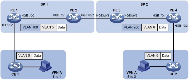
Configuration procedure
1. Configure PE 1:
# Create VLANs 5 and 100.
<PE1> system-view
[PE1] vlan 5
[PE1-vlan5] quit
[PE1] vlan 100
[PE1-vlan100] quit
# Configure a one-to-two VLAN mapping on the customer-side port (HundredGigE 1/0/1) to add SVLAN tag 100 to packets from VLAN 5.
[PE1] interface hundredgige 1/0/1
[PE1-HundredGigE1/0/1] vlan mapping nest single 5 nested-vlan 100
# Configure HundredGigE 1/0/1 as a hybrid port.
[PE1-HundredGigE1/0/1] port link-type hybrid
# Assign HundredGigE 1/0/1 to VLAN 5 as a tagged member.
[PE1-HundredGigE1/0/1] port hybrid vlan 5 tagged
# Assign HundredGigE 1/0/1 to VLAN 100 as an untagged member.
[PE1-HundredGigE1/0/1] port hybrid vlan 100 untagged
[PE1-HundredGigE1/0/1] quit
# Configure the network-side port (HundredGigE 1/0/2) as a trunk port.
[PE1] interface hundredgige 1/0/2
[PE1-HundredGigE1/0/2] port link-type trunk
# Assign HundredGigE 1/0/2 to VLAN 100.
[PE1-HundredGigE1/0/2] port trunk permit vlan 100
[PE1-HundredGigE1/0/2] quit
2. Configure PE 2:
# Create VLAN 100.
<PE2> system-view
[PE2] vlan 100
[PE2-vlan100] quit
# Configure HundredGigE 1/0/1 as a trunk port.
[PE2] interface hundredgige 1/0/1
[PE2-HundredGigE1/0/1] port link-type trunk
# Assign HundredGigE 1/0/1 to VLAN 100.
[PE2-HundredGigE1/0/1] port trunk permit vlan 100
[PE2-HundredGigE1/0/1] quit
# Configure HundredGigE 1/0/2 as a trunk port.
[PE2] interface hundredgige 1/0/2
[PE2-HundredGigE1/0/2] port link-type trunk
# Assign HundredGigE 1/0/2 to VLAN 100.
[PE2-HundredGigE1/0/2] port trunk permit vlan 100
[PE2-HundredGigE1/0/2] quit
3. Configure PE 3:
# Create VLANs 5, 6, 100, and 200.
<PE3> system-view
[PE3] vlan 5 to 6
[PE3] vlan 100
[PE3-vlan100] quit
[PE3] vlan 200
[PE3-vlan200] quit
# Configure HundredGigE 1/0/1 as a trunk port.
[PE3] interface hundredgige 1/0/1
[PE3-HundredGigE1/0/1] port link-type trunk
# Assign HundredGigE 1/0/1 to VLANs 100 and 200.
[PE3-HundredGigE1/0/1] port trunk permit vlan 100 200
# Configure a two-to-two VLAN mapping on HundredGigE 1/0/1 to map SVLAN 100 and CVLAN 5 to SVLAN 200 and CVLAN 6.
[PE3-HundredGigE1/0/1] vlan mapping tunnel 100 5 translated-vlan 200 6
[PE3-HundredGigE1/0/1] quit
# Configure HundredGigE 1/0/2 as a trunk port.
[PE3] interface hundredgige 1/0/2
[PE3-HundredGigE1/0/2] port link-type trunk
# Assign HundredGigE 1/0/2 to VLAN 200.
[PE3-HundredGigE1/0/2] port trunk permit vlan 200
[PE3-HundredGigE1/0/2] quit
4. Configure PE 4:
# Create VLANs 6 and 200.
<PE4> system-view
[PE4] vlan 6
[PE4-vlan6] quit
[PE4] vlan 200
[PE4-vlan200] quit
# Configure the network-side port (HundredGigE 1/0/1) as a trunk port.
[PE4] interface hundredgige 1/0/1
[PE4-HundredGigE1/0/1] port link-type trunk
# Assign HundredGigE 1/0/1 to VLAN 200.
[PE4-HundredGigE1/0/1] port trunk permit vlan 200
[PE4-HundredGigE1/0/1] quit
# Configure the customer-side port (HundredGigE 1/0/2) as a hybrid port.
[PE4] interface hundredgige 1/0/2
[PE4-HundredGigE1/0/2] port link-type hybrid
# Assign HundredGigE 1/0/2 to VLAN 6 as a tagged member.
[PE4-HundredGigE1/0/2] port hybrid vlan 6 tagged
# Assign HundredGigE 1/0/2 to VLAN 200 as an untagged member.
[PE4-HundredGigE1/0/2] port hybrid vlan 200 untagged
# Configure a one-to-two VLAN mapping on HundredGigE 1/0/2 to add SVLAN tag 200 to packets from VLAN 6.
[PE4-HundredGigE1/0/2] vlan mapping nest single 6 nested-vlan 200
[PE4-HundredGigE1/0/2] quit
Verifying the configuration
# Verify VLAN mapping information on PE 1.
[PE1] display vlan mapping
Interface HundredGigE1/0/1:
Outer VLAN Inner VLAN Translated Outer VLAN Translated Inner VLAN
5 N/A 100 5
# Verify VLAN mapping information on PE 3.
[PE3] display vlan mapping
Interface HundredGigE1/0/1:
Outer VLAN Inner VLAN Translated Outer VLAN Translated Inner VLAN
100 5 200 6
# Verify VLAN mapping information on PE 4.
[PE4] display vlan mapping
Interface HundredGigE1/0/2:
Outer VLAN Inner VLAN Translated Outer VLAN Translated Inner VLAN
6 N/A 200 6
Configuring LLDP
Overview
In a heterogeneous network, a standard configuration exchange platform ensures that different types of network devices from different vendors can discover one another and exchange configuration.
The Link Layer Discovery Protocol (LLDP) is specified in IEEE 802.1AB. The protocol operates on the data link layer to exchange device information between directly connected devices. With LLDP, a device sends local device information as TLV (type, length, and value) triplets in LLDP Data Units (LLDPDUs) to the directly connected devices. Local device information includes its system capabilities, management IP address, device ID, port ID, and so on. The device stores the device information in LLDPDUs from the LLDP neighbors in a standard MIB. For more information about MIBs, see Network Management and Monitoring Configuration Guide. LLDP enables a network management system to quickly detect and identify Layer 2 network topology changes.
Basic concepts
LLDP agent
An LLDP agent is a mapping of an entity where LLDP runs. Multiple LLDP agents can run on the same interface.
LLDP agents are divided into the following types:
· Nearest bridge agent.
· Nearest customer bridge agent.
· Nearest non-TPMR bridge agent.
A Two-port MAC Relay (TPMR) is a type of bridge that has only two externally-accessible bridge ports. It supports a subset of the features of a MAC bridge. A TPMR is transparent to all frame-based media-independent protocols except for the following protocols:
· Protocols destined to it.
· Protocols destined to reserved MAC addresses that the relay feature of the TPMR is configured not to forward.
LLDP exchanges packets between neighbor agents and creates and maintains neighbor information for them. Figure 62 shows the neighbor relationships for these LLDP agents. LLDP has two bridge modes: customer bridge (CB) and service bridge (SB).
Figure 62 LLDP neighbor relationships
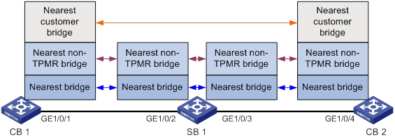
LLDP frame formats
LLDP sends device information in LLDP frames. LLDP frames are encapsulated in Ethernet II or Subnetwork Access Protocol (SNAP) frames.
· LLDP frame encapsulated in Ethernet II
Figure 63 Ethernet II-encapsulated LLDP frame
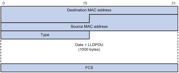
Table 13 Fields in an Ethernet II-encapsulated LLDP frame
|
Field |
Description |
|
Destination MAC address |
MAC address to which the LLDP frame is advertised. LLDP specifies different multicast MAC addresses as destination MAC addresses for LLDP frames destined for agents of different types. This helps distinguish between LLDP frames sent and received by different agent types on the same interface. The destination MAC address is fixed to one of the following multicast MAC addresses: · 0x0180-c200-000E for LLDP frames destined for nearest bridge agents. · 0x0180-c200-0000 for LLDP frames destined for nearest customer bridge agents. · 0x0180-c200-0003 for LLDP frames destined for nearest non-TPMR bridge agents. |
|
Source MAC address |
MAC address of the sending port. |
|
Type |
Ethernet type for the upper-layer protocol. This field is 0x88CC for LLDP. |
|
Data |
LLDPDU. |
|
FCS |
Frame check sequence, a 32-bit CRC value used to determine the validity of the received Ethernet frame. |
· LLDP frame encapsulated in SNAP
Figure 64 SNAP-encapsulated LLDP frame
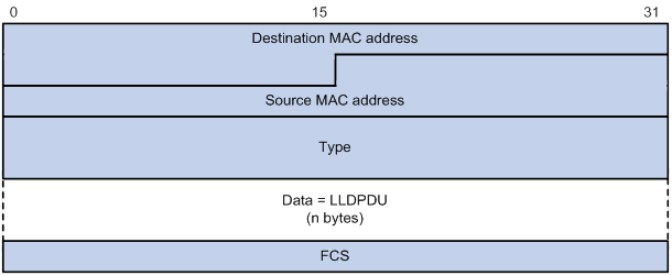
Table 14 Fields in a SNAP-encapsulated LLDP frame
|
Field |
Description |
|
Destination MAC address |
MAC address to which the LLDP frame is advertised. It is the same as that for Ethernet II-encapsulated LLDP frames. |
|
Source MAC address |
MAC address of the sending port. |
|
Type |
SNAP type for the upper-layer protocol. This field is 0xAAAA-0300-0000-88CC for LLDP. |
|
Data |
LLDPDU. |
|
FCS |
Frame check sequence, a 32-bit CRC value used to determine the validity of the received Ethernet frame. |
LLDPDUs
LLDP uses LLDPDUs to exchange information. An LLDPDU comprises multiple TLVs. Each TLV carries a type of device information, as shown in Figure 65.
Figure 65 LLDPDU encapsulation format
![]()
An LLDPDU can carry up to 32 types of TLVs. Mandatory TLVs include Chassis ID TLV, Port ID TLV, Time to Live TLV, and End of LLDPDU TLV. Other TLVs are optional.
TLVs
A TLV is an information element that contains the type, length, and value fields.
LLDPDU TLVs include the following categories:
· Basic management TLVs
· Organizationally (IEEE 802.1 and IEEE 802.3) specific TLVs
· LLDP-MED (media endpoint discovery) TLVs
Basic management TLVs are essential to device management.
Organizationally specific TLVs and LLDP-MED TLVs are used for enhanced device management. They are defined by standardization or other organizations and are optional for LLDPDUs.
· Basic management TLVs
Table 15 lists the basic management TLV types. Some of them are mandatory for LLDPDUs.
Table 15 Basic management TLVs
|
Type |
Description |
Remarks |
|
Chassis ID |
Specifies the bridge MAC address of the sending device. |
Mandatory. |
|
Port ID |
Specifies the ID of the sending port: · If the LLDPDU carries LLDP-MED TLVs, the port ID TLV carries the MAC address of the sending port. · Otherwise, the port ID TLV carries the port name. |
|
|
Time to Live |
Specifies the life of the transmitted information on the receiving device. |
|
|
End of LLDPDU |
Marks the end of the TLV sequence in the LLDPDU. |
|
|
Port Description |
Specifies the description for the sending port. |
Optional. |
|
System Name |
Specifies the assigned name of the sending device. |
|
|
System Description |
Specifies the description for the sending device. |
|
|
System Capabilities |
Identifies the primary features of the sending device and the enabled primary features. |
|
|
Management Address |
Specifies the following elements: · The management address of the local device. · The interface number and object identifier (OID) associated with the address. |
· IEEE 802.1 organizationally specific TLVs
Table 16 IEEE 802.1 organizationally specific TLVs
|
Type |
Description |
|
Port VLAN ID (PVID) |
Specifies the port VLAN identifier. |
|
Port And Protocol VLAN ID (PPVID) |
Indicates whether the device supports protocol VLANs and, if so, what VLAN IDs these protocols will be associated with. |
|
VLAN Name |
Specifies the textual name of any VLAN to which the port belongs. |
|
Protocol Identity |
Indicates protocols supported on the port. |
|
DCBX |
Data center bridging exchange protocol. |
|
EVB module |
Edge Virtual Bridging module, including EVB TLV and CDCP TLV. NOTE: Switches of this series do not support EVB TLVs. |
|
Link Aggregation |
Indicates whether the port supports link aggregation, and if yes, whether link aggregation is enabled. |
|
Management VID |
Management VLAN ID. |
|
VID Usage Digest |
VLAN ID usage digest. |
|
ETS Configuration |
Enhanced Transmission Selection configuration. |
|
ETS Recommendation |
ETS recommendation. |
|
PFC |
Priority-based Flow Control. |
|
APP |
Application protocol. |
|
QCN |
Quantized Congestion Notification. NOTE: Switches of this series do not support QCN TLVs. |
|
|
NOTE: · H3C devices support only receiving protocol identity TLVs and VID usage digest TLVs. · Layer 3 Ethernet ports support only link aggregation TLVs. |
· IEEE 802.3 organizationally specific TLVs
Table 17 IEEE 802.3 organizationally specific TLVs
|
Type |
Description |
|
MAC/PHY Configuration/Status |
Contains the bit-rate and duplex capabilities of the port, support for autonegotiation, enabling status of autonegotiation, and the current rate and duplex mode. |
|
Power Via MDI |
Contains the power supply capabilities of the port: · Port class (PSE or PD). · Power supply mode. · Whether PSE power supply is supported. · Whether PSE power supply is enabled. · Whether pair selection can be controlled. · Power supply type. · Power source. · Power priority. · PD requested power. · PSE allocated power. |
|
Maximum Frame Size |
Indicates the supported maximum frame size. It is now the MTU of the port. |
|
Power Stateful Control |
Indicates the power state control configured on the sending port, including the following: · Power supply mode of the PSE/PD. · PSE/PD priority. · PSE/PD power. |
|
Energy-Efficient Ethernet |
Indicates Energy Efficient Ethernet (EEE). |
|
|
NOTE: The Power Stateful Control TLV is defined in IEEE P802.3at D1.0 and is not supported in later versions. H3C devices send this type of TLVs only after receiving them. |
· LLDP-MED TLVs
LLDP-MED TLVs provide multiple advanced applications for voice over IP (VoIP), such as basic configuration, network policy configuration, and address and directory management. LLDP-MED TLVs provide a cost-effective and easy-to-use solution for deploying voice devices in Ethernet. LLDP-MED TLVs are shown in Table 18.
|
Type |
Description |
|
LLDP-MED Capabilities |
Allows a network device to advertise the LLDP-MED TLVs that it supports. |
|
Network Policy |
Allows a network device or terminal device to advertise the VLAN ID of a port, the VLAN type, and the Layer 2 and Layer 3 priorities for specific applications. |
|
Extended Power-via-MDI |
Allows a network device or terminal device to advertise power supply capability. This TLV is an extension of the Power Via MDI TLV. |
|
Hardware Revision |
Allows a terminal device to advertise its hardware version. |
|
Firmware Revision |
Allows a terminal device to advertise its firmware version. |
|
Software Revision |
Allows a terminal device to advertise its software version. |
|
Serial Number |
Allows a terminal device to advertise its serial number. |
|
Manufacturer Name |
Allows a terminal device to advertise its vendor name. |
|
Model Name |
Allows a terminal device to advertise its model name. |
|
Asset ID |
Allows a terminal device to advertise its asset ID. The typical case is that the user specifies the asset ID for the endpoint to facilitate directory management and asset tracking. |
|
Location Identification |
Allows a network device to advertise the appropriate location identifier information for a terminal device to use in the context of location-based applications. |
|
|
NOTE: · If the MAC/PHY configuration/status TLV is not advertisable, none of the LLDP-MED TLVs will be advertised even if they are advertisable. · If the LLDP-MED capabilities TLV is not advertisable, the other LLDP-MED TLVs will not be advertised even if they are advertisable. |
Management address
The network management system uses the management address of a device to identify and manage the device for topology maintenance and network management. The management address is encapsulated in the management address TLV.
Working mechanism
LLDP operating modes
An LLDP agent can operate in one of the following modes:
· TxRx mode—An LLDP agent in this mode can send and receive LLDP frames.
· Tx mode—An LLDP agent in this mode can only send LLDP frames.
· Rx mode—An LLDP agent in this mode can only receive LLDP frames.
· Disable mode—An LLDP agent in this mode cannot send or receive LLDP frames.
Each time the LLDP operating mode of an LLDP agent changes, its LLDP protocol state machine reinitializes. A configurable reinitialization delay prevents frequent initializations caused by frequent changes to the operating mode. If you configure the reinitialization delay, an LLDP agent must wait the specified amount of time to initialize LLDP after the LLDP operating mode changes.
Transmitting LLDP frames
An LLDP agent operating in TxRx mode or Tx mode sends LLDP frames to its directly connected devices both periodically and when the local configuration changes. To prevent LLDP frames from overwhelming the network during times of frequent changes to local device information, LLDP uses the token bucket mechanism to rate limit LLDP frames. For more information about the token bucket mechanism, see ACL and QoS Configuration Guide.
LLDP automatically enables the fast LLDP frame transmission mechanism in either of the following cases:
· A new LLDP frame is received and carries device information new to the local device.
· The LLDP operating mode of the LLDP agent changes from Disable or Rx to TxRx or Tx.
The fast LLDP frame transmission mechanism successively sends the specified number of LLDP frames at a configurable fast LLDP frame transmission interval. The mechanism helps LLDP neighbors discover the local device as soon as possible. Then, the normal LLDP frame transmission interval resumes.
Receiving LLDP frames
An LLDP agent operating in TxRx mode or Rx mode confirms the validity of TLVs carried in every received LLDP frame. If the TLVs are valid, the LLDP agent saves the information and starts an aging timer. The initial value of the aging timer is equal to the TTL value in the Time To Live TLV carried in the LLDP frame. When the LLDP agent receives a new LLDP frame, the aging timer restarts. When the aging timer decreases to zero, all saved information ages out.
Protocols and standards
· IEEE 802.1AB-2005, Station and Media Access Control Connectivity Discovery
· IEEE 802.1AB-2009, Station and Media Access Control Connectivity Discovery
· ANSI/TIA-1057, Link Layer Discovery Protocol for Media Endpoint Devices
· DCB Capability Exchange Protocol Specification Rev 1.00
· DCB Capability Exchange Protocol Base Specification Rev 1.01
· IEEE Std 802.1Qaz-2011, Media Access Control (MAC) Bridges and Virtual Bridged Local Area Networks-Amendment 18: Enhanced Transmission Selection for Bandwidth Sharing Between Traffic Classes
LLDP configuration task list
|
Tasks at a glance |
|
Performing basic LLDP configurations: · (Required.) Enabling LLDP · (Optional.) Setting the LLDP bridge mode · (Optional.) Setting the LLDP operating mode · (Optional.) Setting the LLDP reinitialization delay · (Optional.) Enabling LLDP polling · (Optional.) Configuring the advertisable TLVs · (Optional.) Configuring the management address and its encoding format · (Optional.) Setting other LLDP parameters · (Optional.) Setting an encapsulation format for LLDP frames · (Optional.) Disabling LLDP PVID inconsistency check |
|
(Optional.) Configuring CDP compatibility |
|
(Optional.) Configuring DCBX |
|
(Optional.) Configuring LLDP trapping and LLDP-MED trapping |
|
(Optional.) Setting the source MAC address of LLDP frames |
|
(Optional.) Enabling the device to generate ARP or ND entries for received management address LLDP TLVs |
Performing basic LLDP configurations
Enabling LLDP
To make LLDP take effect on specific ports, you must enable LLDP both globally and on these ports.
To use LLDP together with OpenFlow, you must enable LLDP globally on OpenFlow switches. To prevent LLDP from affecting topology discovery of OpenFlow controllers, disable LLDP on ports of OpenFlow instances. For more information about OpenFlow, see OpenFlow Configuration Guide.
To enable LLDP:
|
Step |
Command |
Remarks |
|
1. Enter system view. |
system-view |
N/A |
|
2. Enable LLDP globally. |
lldp global enable |
By default, LLDP is disabled globally. |
|
3. Enter Layer 2/Layer 3 Ethernet interface view, management Ethernet interface view, Layer 2/Layer 3 aggregate interface view, or IRF physical interface view. |
interface interface-type interface-number |
N/A |
|
4. Enable LLDP. |
lldp enable |
By default, LLDP is enabled on a port. |
|
|
NOTE: An LLDP-enabled IRF physical interface supports only the nearest bridge agents. |
Setting the LLDP bridge mode
The following LLDP bridge modes are available:
· Customer bridge mode—LLDP supports nearest bridge agents, nearest non-TPMR bridge agents, and nearest customer bridge agents. LLDP processes the LLDP frames with destination MAC addresses for these agents and transparently transmits the LLDP frames with other destination MAC addresses in the VLAN.
· Service bridge mode—LLDP supports nearest bridge agents and nearest non-TPMR bridge agents. LLDP processes the LLDP frames with destination MAC addresses for these agents and transparently transmits the LLDP frames with other destination MAC addresses in the VLAN.
To set the LLDP bridge mode:
|
Step |
Command |
Remarks |
|
1. Enter system view. |
system-view |
N/A |
|
2. Set the LLDP bridge mode to service bridge. |
lldp mode service-bridge |
By default, LLDP operates in customer bridge mode. |
Setting the LLDP operating mode
|
Step |
Command |
Remarks |
|
1. Enter system view. |
system-view |
N/A |
|
2. Enter Layer 2/Layer 3 Ethernet interface view, management Ethernet interface view, Layer 2/Layer 3 aggregate interface view, or IRF physical interface view. |
interface interface-type interface-number |
N/A |
|
3. Set the LLDP operating mode. |
·
In Layer 2/Layer 3 Ethernet interface
view or management Ethernet interface view: ·
In Layer 2/Layer 3 aggregate interface view: ·
In IRF physical interface view: |
By default: · The nearest bridge agent operates in txrx mode. · The nearest customer bridge agent and nearest non-TPMR bridge agent operate in disable mode. In Ethernet interface view, if you do not specify an agent type, the command sets the operating mode for nearest bridge agents. In aggregate interface view, you can set the operating mode only for nearest customer bridge agents and nearest non-TPMR bridge agents. In IRF physical interface view, you can set the operating mode only for nearest bridge agents. |
Setting the LLDP reinitialization delay
When the LLDP operating mode changes on a port, the port initializes the protocol state machines after an LLDP reinitialization delay. By adjusting the delay, you can avoid frequent initializations caused by frequent changes to the LLDP operating mode on a port.
To set the LLDP reinitialization delay for ports:
|
Step |
Command |
Remarks |
|
1. Enter system view. |
system-view |
N/A |
|
2. Set the LLDP reinitialization delay. |
lldp timer reinit-delay delay |
The default setting is 2 seconds. |
Enabling LLDP polling
With LLDP polling enabled, a device periodically searches for local configuration changes. When the device detects a configuration change, it sends LLDP frames to inform neighboring devices of the change.
To enable LLDP polling:
|
Step |
Command |
Remarks |
|
1. Enter system view. |
system-view |
N/A |
|
2. Enter Layer 2/Layer 3 Ethernet interface view, management Ethernet interface view, Layer 2/Layer 3 aggregate interface view, or IRF physical interface view. |
interface interface-type interface-number |
N/A |
|
3. Enable LLDP polling and set the polling interval. |
·
In Layer 2/Layer 3 Ethernet interface
view or management Ethernet interface view: ·
In Layer 2/Layer 3 aggregate interface view: ·
In IRF physical interface view: |
By default, LLDP polling is disabled. |
Configuring the advertisable TLVs
|
Step |
Command |
Remarks |
|
1. Enter system view. |
system-view |
N/A |
|
2. Enter Layer 2/Layer 3 Ethernet interface view, management Ethernet interface view, Layer 2/Layer 3 aggregate interface view, or IRF physical interface view. |
interface interface-type interface-number |
N/A |
|
3. Configure the advertisable TLVs (in Layer 2 Ethernet interface view). |
· lldp tlv-enable { basic-tlv { all | port-description | system-capability | system-description | system-name | management-address-tlv [ ipv6 ] [ ip-address ] } | dot1-tlv { all | port-vlan-id | link-aggregation | dcbx | protocol-vlan-id [ vlan-id ] | vlan-name [ vlan-id ] | management-vid [ mvlan-id ] } | dot3-tlv { all | mac-physic | max-frame-size | power } | med-tlv { all | capability | inventory | network-policy [ vlan-id ] | power-over-ethernet | location-id { civic-address device-type country-code { ca-type ca-value }&<1-10> | elin-address tel-number } } } · lldp agent nearest-nontpmr tlv-enable { basic-tlv { all | port-description | system-capability | system-description | system-name | management-address-tlv [ ipv6 ] [ ip-address ] } | dot1-tlv { all | port-vlan-id | link-aggregation } } · lldp agent nearest-customer tlv-enable { basic-tlv { all | port-description | system-capability | system-description | system-name | management-address-tlv [ ipv6 ] [ ip-address ] } | dot1-tlv { all | port-vlan-id | link-aggregation } } |
By default: · Nearest bridge agents can advertise all LLDP TLVs except the DCBX, location identification, port and protocol VLAN ID, VLAN name, and management VLAN ID TLVs. · Nearest non-TPMR bridge agents do not advertise TLVs. · Nearest customer bridge agents can advertise basic TLVs and IEEE 802.1 organizationally specific TLVs. |
|
4. Configure the advertisable TLVs (in Layer 3 Ethernet interface view). |
· lldp tlv-enable { basic-tlv { all | port-description | system-capability | system-description | system-name | management-address-tlv [ ipv6 ] [ ip-address | interface loopback interface-number ] } | dot1-tlv { all | link-aggregation } | dot3-tlv { all | mac-physic | max-frame-size | power } | med-tlv { all | capability | inventory | power-over-ethernet | location-id { civic-address device-type country-code { ca-type ca-value }&<1-10> | elin-address tel-number } } } · lldp agent { nearest-nontpmr | nearest-customer } tlv-enable { basic-tlv { all | port-description | system-capability | system-description | system-name | management-address-tlv [ ipv6 ] [ ip-address ] } | dot1-tlv { all | link-aggregation } } |
By default: · Nearest bridge agents can advertise all types of LLDP TLVs (only link aggregation TLV is supported in 802.1 organizationally specific TLVs) except network policy TLVs. · Nearest non-TPMR bridge agents do not advertise TLVs. · Nearest customer bridge agents can advertise basic TLVs and IEEE 802.1 organizationally specific TLVs (only link aggregation TLV is supported). |
|
5. Configure the advertisable TLVs (in management Ethernet interface view). |
· lldp tlv-enable { basic-tlv { all | port-description | system-capability | system-description | system-name | management-address-tlv [ ipv6 ] [ ip-address ] } | dot1-tlv { all | link-aggregation } | dot3-tlv { all | mac-physic | max-frame-size | power } | med-tlv { all | capability | inventory | power-over-ethernet | location-id { civic-address device-type country-code { ca-type ca-value }&<1-10> | elin-address tel-number } } } · lldp agent { nearest-nontpmr | nearest-customer } tlv-enable { basic-tlv { all | port-description | system-capability | system-description | system-name | management-address-tlv [ ipv6 ] [ ip-address ] } | dot1-tlv { all | link-aggregation } } |
By default: · Nearest bridge agents can advertise all types of LLDP TLVs (only link aggregation TLV is supported in 802.1 organizationally specific TLVs) except network policy TLVs. · Nearest non-TPMR bridge agents do not advertise TLVs. · Nearest customer bridge agents can advertise basic TLVs and IEEE 802.1 organizationally specific TLVs (only link aggregation TLV is supported). |
|
6. Configure the advertisable TLVs (in Layer 2 aggregate interface view). |
· lldp agent nearest-nontpmr tlv-enable { basic-tlv { all | management-address-tlv [ ipv6 ] [ ip-address ] | port-description | system-capability | system-description | system-name } | dot1-tlv { all | port-vlan-id } } · lldp agent nearest-customer tlv-enable { basic-tlv { all | management-address-tlv [ ipv6 ] [ ip-address ] | port-description | system-capability | system-description | system-name } | dot1-tlv { all | port-vlan-id } } · lldp tlv-enable dot1-tlv { protocol-vlan-id [ vlan-id ] | vlan-name [ vlan-id ] | management-vid [ mvlan-id ] } |
By default: · Nearest non-TPMR bridge agents do not advertise TLVs. · Nearest customer bridge agents can advertise basic TLVs and IEEE 802.1 organizationally specific TLVs (only port and protocol VLAN ID, VLAN name, and management VLAN ID TLVs are supported). Nearest bridge agents are not supported on Layer 2 aggregate interfaces. |
|
7. Configure the advertisable TLVs (in Layer 3 aggregate interface view). |
lldp agent { nearest-nontpmr | nearest-customer } tlv-enable basic-tlv { all | management-address-tlv [ ipv6 ] [ ip-address ] | port-description | system-capability | system-description | system-name } |
By default: · Nearest non-TPMR bridge agents do not advertise TLVs. · Nearest customer bridge agents can advertise only basic TLVs. Nearest bridge agents are not supported on Layer 3 aggregate interfaces. |
|
8. Configure the advertisable TLVs (in IRF physical interface view). |
lldp tlv-enable basic-tlv { port-description | system-capability | system-description | system-name } |
An LLDP-enabled IRF physical interface supports only the nearest bridge agent. By default, nearest bridge agents can advertise all types of LLDP TLVs. |
Configuring the management address and its encoding format
LLDP encodes management addresses in numeric or string format in management address TLVs.
If a neighbor encodes its management address in string format, set the encoding format of the management address to string on the connecting port. This guarantees normal communication with the neighbor.
To configure a management address to be advertised and its encoding format on a port:
|
Step |
Command |
Remarks |
|
1. Enter system view. |
system-view |
N/A |
|
2. Enter Layer 2/Layer 3 Ethernet interface view, management Ethernet interface view, or Layer 2/Layer 3 aggregate interface view. |
interface interface-type interface-number |
N/A |
|
3. Allow LLDP to advertise the management address in LLDP frames and configure the advertised management address. |
·
In Layer 2 Ethernet interface view or
management Ethernet interface view: ·
In Layer 3 Ethernet interface view: ·
In Layer 2/Layer 3 aggregate interface view: |
By default: · Nearest bridge agents and nearest customer bridge agents can advertise the management address in LLDP frames. · Nearest non-TPMR bridge agents cannot advertise the management address in LLDP frames. |
|
4. Set the encoding format of the management address to string. |
·
In Layer 2/Layer 3 Ethernet interface
view or management Ethernet interface view: ·
In Layer 2/Layer 3 aggregate interface
view: |
By default, the encoding format of the management address is numeric. |
Setting other LLDP parameters
The Time to Live TLV carried in an LLDPDU determines how long the device information carried in the LLDPDU can be saved on a recipient device.
By setting the TTL multiplier, you can configure the TTL of locally sent LLDPDUs. The TTL is expressed by using the following formula:
TTL = Min (65535, (TTL multiplier × LLDP frame transmission interval + 1))
As the expression shows, the TTL can be up to 65535 seconds. TTLs greater than 65535 will be rounded down to 65535 seconds.
To set LLDP parameters:
|
Step |
Command |
Remarks |
|
1. Enter system view. |
system-view |
N/A |
|
2. Set the TTL multiplier. |
lldp hold-multiplier value |
The default setting is 4. |
|
3. Set the LLDP frame transmission interval. |
lldp timer tx-interval interval |
The default setting is 30 seconds. |
|
4. Set the token bucket size for sending LLDP frames. |
lldp max-credit credit-value |
The default setting is 5. |
|
5. Set the number of LLDP frames sent each time fast LLDP frame transmission is triggered. |
lldp fast-count count |
The default setting is 4. |
|
6. Set the fast LLDP frame transmission interval. |
lldp timer fast-interval interval |
The default setting is 1 second. |
Setting an encapsulation format for LLDP frames
LLDP frames can be encapsulated in the following formats:
· Ethernet II—With Ethernet II encapsulation configured, an LLDP port sends LLDP frames in Ethernet II frames.
· SNAP—With SNAP encapsulation configured, an LLDP port sends LLDP frames in SNAP frames.
Earlier versions of LLDP require the same encapsulation format on both ends to process LLDP frames. To successfully communicate with a neighboring device running an earlier version of LLDP, the local device must be set with the same encapsulation format.
To set the encapsulation format for LLDP frames to SNAP:
|
Step |
Command |
Remarks |
|
1. Enter system view. |
system-view |
N/A |
|
2. Enter Layer 2/Layer 3 Ethernet interface view, management Ethernet interface view, Layer 2/Layer 3 aggregate interface view, or IRF physical interface view. |
interface interface-type interface-number |
N/A |
|
3. Set the encapsulation format for LLDP frames to SNAP. |
·
In Layer 2/Layer 3 Ethernet interface
view or management Ethernet interface view: ·
In Layer 2/Layer 3 aggregate interface
view: ·
In IRF physical interface view: |
By default, Ethernet II encapsulation format applies. |
Disabling LLDP PVID inconsistency check
By default, when the system receives an LLDP packet, it compares the PVID value contained in packet with the PVID configured on the receiving interface. If the two PVIDs do not match, a log message will be printed to notify the user.
You can disable PVID inconsistency check if different PVIDs are required on a link.
To disable LLDP PVID inconsistency check:
|
Step |
Command |
Remarks |
|
1. Enter system view. |
system-view |
N/A |
|
2. Disable LLDP PVID inconsistency check. |
lldp ignore-pvid-inconsistency |
By default, LLDP PVID inconsistency check is enabled. |
Configuring CDP compatibility
To enable your device to exchange information with a directly connected Cisco device that supports only CDP, you must enable CDP compatibility.
CDP compatibility enables your device to receive and recognize CDP packets from the neighboring CDP device and send CDP packets to the neighboring device. The CDP packets sent to the neighboring CDP device carry the following information:
· Device ID.
· ID of the port connecting to the neighboring device.
· Port IP address.
· TTL.
The port IP address is the primary IP address of a VLAN interface in up state. The VLAN ID of the VLAN interface must be the lowest among the VLANs permitted on the port. If no VLAN interfaces of the permitted VLANs are assigned an IP address or all VLAN interfaces are down, no port IP address will be advertised.
You can view the neighboring CDP device information that can be recognized by the device in the output of the display lldp neighbor-information command. For more information about the display lldp neighbor-information command, see Layer 2—LAN Switching Command Reference.
Configuration prerequisites
Before you configure CDP compatibility, complete the following tasks:
· Globally enable LLDP.
· Enable LLDP on the port connecting to a CDP device.
· Configure LLDP to operate in TxRx mode on the port.
Configuration procedure
CDP-compatible LLDP operates in one of the following modes:
· TxRx—CDP packets can be transmitted and received.
· Rx—CDP packets can be received but cannot be transmitted.
· Disable—CDP packets cannot be transmitted or received.
To make CDP-compatible LLDP take effect on a port, follow these steps:
1. Enable CDP-compatible LLDP globally.
2. Configure CDP-compatible LLDP to operate in TxRx mode on the port.
The maximum TTL value that CDP allows is 255 seconds. To make CDP-compatible LLDP work correctly with CDP devices, configure the LLDP frame transmission interval to be no more than 1/3 of the TTL value.
To configure LLDP to be compatible with CDP:
|
Step |
Command |
Remarks |
|
1. Enter system view. |
system-view |
N/A |
|
2. Enable CDP compatibility globally. |
lldp compliance cdp |
By default, CDP compatibility is disabled globally. |
|
3. Enter Layer 2/Layer 3 Ethernet interface view, management Ethernet interface view, or Layer 2/Layer 3 aggregate interface view. |
interface interface-type interface-number |
N/A |
|
4. Configure CDP-compatible LLDP to operate in TxRx mode. |
lldp compliance admin-status cdp txrx |
By default, CDP-compatible LLDP operates in disable mode. |
Configuring DCBX
Data Center Ethernet (DCE), also known as Converged Enhanced Ethernet (CEE), is enhancement and expansion of traditional Ethernet local area networks for use in data centers. DCE uses the Data Center Bridging Exchange Protocol (DCBX) to negotiate and remotely configure the bridge capability of network elements.
DCBX has the following self-adaptable versions:
· DCB Capability Exchange Protocol Specification Rev 1.00.
· DCB Capability Exchange Protocol Base Specification Rev 1.01.
· IEEE Std 802.1Qaz-2011 (Media Access Control (MAC) Bridges and Virtual Bridged Local Area Networks-Amendment 18: Enhanced Transmission Selection for Bandwidth Sharing Between Traffic Classes).
DCBX offers the following functions:
· Discovers the peer devices' capabilities and determines whether devices at both ends support these capabilities.
· Detects configuration errors on peer devices.
· Remotely configures the peer device if the peer device accepts the configuration.
|
|
NOTE: H3C devices support only the remote configuration feature. |
Figure 66 DCBX application scenario
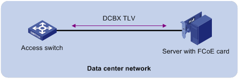
DCBX enables lossless packet transmission on DCE networks.
As shown in Figure 66, DCBX applies to an FCoE-based data center network, and operates on an access switch. DCBX enables the switch to control the server or storage adapter, and simplifies the configuration and guarantees configuration consistency. DCBX extends LLDP by using the IEEE 802.1 organizationally specific TLVs (DCBX TLVs) to transmit DCBX data, including:
· In DCBX Rev 1.00 and DCBX Rev 1.01:
? Application Protocol (APP).
? Enhanced Transmission Selection (ETS).
? Priority-based Flow Control (PFC).
· In IEEE Std 802.1Qaz-2011:
? ETS Configuration.
? ETS Recommendation.
? PFC.
? APP.
DCBX configuration task list
|
Tasks at a glance |
|
|
(Required.) Enabling LLDP and DCBX TLV advertising |
|
|
(Required.) Setting the DCBX version |
|
|
(Required.) Configuring ETS parameters |
|
|
(Required.) Configuring PFC parameters |
Enabling LLDP and DCBX TLV advertising
To enable the device to advertise APP, ETS, and PFC data through an interface, perform the following tasks:
· Enable LLDP globally.
· Enable LLDP and DCBX TLV advertising on the interface.
To enable LLDP and DCBX TLV advertising:
|
Step |
Command |
Remarks |
|
1. Enter system view. |
system-view |
N/A |
|
2. Enable LLDP globally. |
lldp global enable |
By default, LLDP is disabled globally. |
|
3. Enter Layer 2 Ethernet interface view. |
interface interface-type interface-number |
N/A |
|
4. Enable LLDP. |
lldp enable |
By default, LLDP is enabled on an interface. |
|
5. Enable the interface to advertise DCBX TLVs. |
lldp tlv-enable dot1-tlv dcbx |
By default, DCBX TLV advertising is disabled on an interface. |
Setting the DCBX version
When you set the DCBX version, follow these restrictions and guidelines:
· For DCBX to work correctly, configure the same DCBX version on the local port and peer port. As a best practice, configure the highest version supported on both ends. IEEE Std 802.1Qaz-2011, DCBX Rev 1.01, and DCBX Rev 1.00 are in descending order.
· After the configuration, LLDP frames sent by the local port carry information about the configured DCBX version. The local port and peer port do not negotiate the DCBX version.
· When the DCBX version is autonegotiated, the version IEEE Std 802.1Qaz-2011 is preferably negotiated.
To set the DCBX version:
|
Step |
Command |
Remarks |
|
1. Enter system view. |
system-view |
N/A |
|
2. Enter Layer 2 Ethernet interface view. |
interface interface-type interface-number |
N/A |
|
3. Set the DCBX version. |
dcbx version { rev100 | rev101 | standard } |
By default, the DCBX version is not configured. It is autonegotiated by the local port and peer port. |
Configuring ETS parameters
ETS provides committed bandwidth. To avoid packet loss caused by congestion, the device performs the following operations:
· Uses ETS parameters to negotiate with the server adapter.
· Controls the server adapter's transmission speed of the specified type of traffic.
· Guarantees that the transmission speed is within the committed bandwidth of the interface.
To configure ETS parameters, you must configure the 802.1p-to-local priority mapping and group-based WRR queuing.
Configuring the 802.1p-to-local priority mapping
You can configure the 802.1p-to-local priority mapping either in the MQC method or in the priority mapping table method. If you configure the 802.1p-to-local priority mapping in both methods, the configuration made in the MQC method applies.
To configure the 802.1p-to-local priority mapping in the MQC method:
|
Step |
Command |
Remarks |
|
1. Enter system view. |
system-view |
N/A |
|
2. Create a traffic class, specify the operator of the class as OR, and enter class view. |
traffic classifier classifier-name operator or |
By default, no traffic class exists. |
|
3. Configure the class to match packets with the specified service provider network 802.1p priority values. |
if-match service-dot1p 8021p-list |
By default, no match criterion is configured for the class to match packets. |
|
4. Return to system view. |
quit |
N/A |
|
5. Create a traffic behavior and enter traffic behavior view. |
traffic behavior behavior-name |
By default, no traffic behavior exists. |
|
6. Configure the behavior to mark packets with the specified local precedence value. |
remark local-precedence local-precedence |
By default, no local precedence marking action is configured. |
|
7. Return to system view. |
quit |
N/A |
|
8. Create a QoS policy and enter QoS policy view. |
qos policy policy-name |
By default, no policy exists. |
|
9. Associate the class with the traffic behavior in the QoS policy, and apply the association to DCBX. |
classifier classifier-name behavior behavior-name mode dcbx |
By default, no class-behavior association exists. |
For more information about the traffic classifier, if-match, traffic behavior, remark local-precedence, qos policy, and classifier behavior commands, see ACL and QoS Command Reference.
To configure the 802.1p priority mapping in the priority mapping table method:
|
Step |
Command |
Remarks |
|
1. Enter system view. |
system-view |
N/A |
|
2. Enter 802.1p-to-local priority mapping table view. |
qos map-table dot1p-lp |
N/A |
|
3. Configure the priority mapping table to map the specified 802.1p priority values to a local precedence value. |
import import-value-list export export-value |
For information about the default priority mapping tables, see ACL and QoS Configuration Guide. |
For more information about the qos map-table and import commands, see ACL and QoS Command Reference.
Configuring group-based WRR queuing
You can configure group-based WRR queuing to allocate bandwidth.
To configure group-based WRR queuing:
|
Step |
Command |
Remarks |
|
1. Enter system view. |
system-view |
N/A |
|
2. Enter Layer 2 Ethernet interface view. |
interface interface-type interface-number |
N/A |
|
3. Enable WRR queuing. |
qos wrr byte-count |
By default, byte-count WRR queuing is enabled on an interface. |
|
4. Configure a queue. |
·
Add a queue to WRR priority group 1 and
configure the scheduling weight for the queue: ·
Configure a queue to use SP queuing: |
Use one or both commands. |
For more information about the qos wrr, qos wrr byte-count, and qos wrr group sp commands, see ACL and QoS Command Reference.
Configuring PFC parameters
To prevent packets with an 802.1p priority value from being dropped, enable PFC for the 802.1p priority value. This feature reduces the sending rate of packets carrying this priority when network congestion occurs.
The device uses PFC parameters to negotiate with the server adapter and to enable PFC for the specified 802.1p priorities on the server adapter.
To configure PFC parameters:
|
Step |
Command |
Remarks |
|
1. Enter system view. |
system-view |
N/A |
|
2. Enter Layer 2 Ethernet interface view. |
interface interface-type interface-number |
N/A |
|
3. Enable PFC in auto mode on the Ethernet interface. |
priority-flow-control auto |
By default, PFC is disabled. To advertise the PFC data, you must enable PFC in auto mode. |
|
4. Enable PFC for the specified 802.1p priorities. |
priority-flow-control no-drop dot1p dot1p-list |
By default, PFC is disabled for all 802.1p priorities. |
For more information about the priority-flow-control and priority-flow-control no-drop dot1p commands, see Interface Command Reference.
Configuring LLDP trapping and LLDP-MED trapping
LLDP trapping or LLDP-MED trapping notifies the network management system of events such as newly detected neighboring devices and link failures.
To prevent excessive LLDP traps from being sent when the topology is unstable, set a trap transmission interval for LLDP.
To configure LLDP trapping and LLDP-MED trapping:
|
Step |
Command |
Remarks |
|
1. Enter system view. |
system-view |
N/A |
|
2. Enter Layer 2/Layer 3 Ethernet interface view, management Ethernet interface view, Layer 2/Layer 3 aggregate interface view, or IRF physical interface view. |
interface interface-type interface-number |
N/A |
|
3. Enable LLDP trapping. |
·
In Layer 2/Layer 3 Ethernet interface
view or management Ethernet interface view: ·
In Layer 2/Layer 3 aggregate interface
view: ·
In IRF physical interface view: |
By default, LLDP trapping is disabled. |
|
4. Enable LLDP-MED trapping (in Layer 2/Layer 3 Ethernet interface view or management Ethernet interface view). |
lldp notification med-topology-change enable |
By default, LLDP-MED trapping is disabled. |
|
5. Return to system view. |
quit |
N/A |
|
6. (Optional.) Set the LLDP trap transmission interval. |
lldp timer notification-interval interval |
The default setting is 30 seconds. |
Setting the source MAC address of LLDP frames
|
Step |
Command |
Remarks |
|
1. Enter system view. |
system-view |
N/A |
|
2. Enter Layer 2 or Layer 3 Ethernet interface view. |
interface interface-type interface-number |
N/A |
|
3. Set the source MAC address of LLDP frames to the MAC address of a VLAN interface or a Layer 3 Ethernet subinterface. |
lldp source-mac vlan vlan-id |
By default, the source MAC address of LLDP frames is the MAC address of the egress interface. In Layer 3 Ethernet interface view, the specified VLAN ID is used as the subnumber element of the Layer 3 Ethernet subinterface number interface-number.subnumber. |
Enabling the device to generate ARP or ND entries for received management address LLDP TLVs
This feature enables the device to generate an ARP or ND entry for a received LLDP frame that carries a management address TLV. The ARP or ND entry contains the management address and the source MAC address of the frame.
You can enable the device to generate both ARP and ND entries. If the management address TLV contains an IPv4 address, the device generates an ARP entry. If the management address TLV contains an IPv6 address, the device generates an ND entry.
To enable the device to generate an ARP or ND entry for a received management address LLDP TLV:
|
Step |
Command |
Remarks |
|
1. Enter system view. |
system-view |
N/A |
|
2. Enter Layer 2 or Layer 3 Ethernet interface view. |
interface interface-type interface-number |
N/A |
|
3. Enable the device to generate an ARP or ND entry for a management address LLDP TLV received on the interface. |
·
In Layer 2 Ethernet interface view: ·
In Layer 3 Ethernet interface view: |
By default, the device does not generate an ARP or ND entry when receiving a management address LLDP TLV. In Layer 3 Ethernet interface view, this option enables LLDP to generate the ARP or ND entry for the Layer 3 Ethernet subinterface identified by interface-number.subnumber, where subnumber is the specified VLAN ID. Do not specify the same VLAN for multiple interfaces. Otherwise, the ARP or ND entries for different interfaces might overwrite one another. |
Displaying and maintaining LLDP
Execute display commands in any view.
|
Command |
|
|
Display local LLDP information. |
display lldp local-information [ global | interface interface-type interface-number ] |
|
Display the information contained in the LLDP TLVs sent from neighboring devices. |
display lldp neighbor-information [ [ [ interface interface-type interface-number ] [ agent { nearest-bridge | nearest-customer | nearest-nontpmr } ] [ verbose ] ] | list [ system-name system-name ] ] |
|
Display LLDP statistics. |
display lldp statistics [ global | [ interface interface-type interface-number ] [ agent { nearest-bridge | nearest-customer | nearest-nontpmr } ] ] |
|
Display LLDP status of a port. |
display lldp status [ interface interface-type interface-number ] [ agent { nearest-bridge | nearest-customer | nearest-nontpmr } ] |
|
Display types of advertisable optional LLDP TLVs. |
display lldp tlv-config [ interface interface-type interface-number ] [ agent { nearest-bridge | nearest-customer | nearest-nontpmr } ] |
Basic LLDP configuration example
Network requirements
As shown in Figure 67, enable LLDP globally on Switch A and Switch B to perform the following tasks:
· Monitor the link between Switch A and Switch B on the NMS.
· Monitor the link between Switch A and the MED device on the NMS.
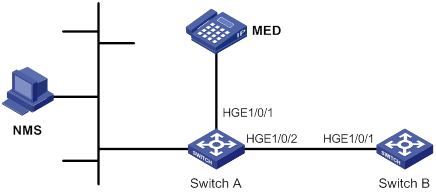
Configuration procedure
1. Configure Switch A:
# Enable LLDP globally.
<SwitchA> system-view
[SwitchA] lldp global enable
# Enable LLDP on HundredGigE 1/0/1. By default, LLDP is enabled on ports.
[SwitchA] interface hundredgige 1/0/1
[SwitchA-HundredGigE1/0/1] lldp enable
# Set the LLDP operating mode to Rx on HundredGigE 1/0/1.
[SwitchA-HundredGigE1/0/1] lldp admin-status rx
[SwitchA-HundredGigE1/0/1] quit
# Enable LLDP on HundredGigE 1/0/2. By default, LLDP is enabled on ports.
[SwitchA] interface hundredgige 1/0/2
[SwitchA-HundredGigE1/0/2] lldp enable
# Set the LLDP operating mode to Rx on HundredGigE 1/0/2.
[SwitchA-HundredGigE1/0/2] lldp admin-status rx
[SwitchA-HundredGigE1/0/2] quit
2. Configure Switch B:
# Enable LLDP globally.
<SwitchB> system-view
[SwitchB] lldp global enable
# Enable LLDP on HundredGigE 1/0/1. By default, LLDP is enabled on ports.
[SwitchB] interface hundredgige 1/0/1
[SwitchB-HundredGigE1/0/1] lldp enable
# Set the LLDP operating mode to Tx on HundredGigE 1/0/1.
[SwitchB-HundredGigE1/0/1] lldp admin-status tx
[SwitchB-HundredGigE1/0/1] quit
Verifying the configuration
# Verify the following items:
· HundredGigE 1/0/1 of Switch A connects to a MED device.
· HundredGigE 1/0/2 of Switch A connects to a non-MED device.
· Both ports operate in Rx mode, and they can receive LLDP frames but cannot send LLDP frames.
[SwitchA] display lldp status
Global status of LLDP: Enable
Bridge mode of LLDP: customer-bridge
The current number of LLDP neighbors: 2
The current number of CDP neighbors: 0
LLDP neighbor information last changed time: 0 days, 0 hours, 4 minutes, 40 seconds
Transmit interval : 30s
Fast transmit interval : 1s
Transmit credit max : 5
Hold multiplier : 4
Reinit delay : 2s
Trap interval : 30s
Fast start times : 4
LLDP status information of port 1 [HundredGigE1/0/1]:
LLDP agent nearest-bridge:
Port status of LLDP : Enable
Admin status : Rx_Only
Trap flag : No
MED trap flag : No
Polling interval : 0s
Number of LLDP neighbors : 1
Number of MED neighbors : 1
Number of CDP neighbors : 0
Number of sent optional TLV : 21
Number of received unknown TLV : 0
LLDP agent nearest-customer:
Port status of LLDP : Enable
Admin status : Disable
Trap flag : No
MED trap flag : No
Polling interval : 0s
Number of LLDP neighbors : 0
Number of MED neighbors : 0
Number of CDP neighbors : 0
Number of sent optional TLV : 16
Number of received unknown TLV : 0
LLDP status information of port 2 [HundredGigE1/0/2]:
LLDP agent nearest-bridge:
Port status of LLDP : Enable
Admin status : Rx_Only
Trap flag : No
MED trap flag : No
Polling interval : 0s
Number of LLDP neighbors : 1
Number of MED neighbors : 0
Number of CDP neighbors : 0
Number of sent optional TLV : 21
Number of received unknown TLV : 3
LLDP agent nearest-nontpmr:
Port status of LLDP : Enable
Admin status : Disable
Trap flag : No
MED trap flag : No
Polling interval : 0s
Number of LLDP neighbors : 0
Number of MED neighbors : 0
Number of CDP neighbors : 0
Number of sent optional TLV : 1
Number of received unknown TLV : 0
LLDP agent nearest-customer:
Port status of LLDP : Enable
Admin status : Disable
Trap flag : No
MED trap flag : No
Polling interval : 0s
Number of LLDP neighbors : 0
Number of MED neighbors : 0
Number of CDP neighbors : 0
Number of sent optional TLV : 16
Number of received unknown TLV : 0
# Remove the link between Switch A and Switch B.
# Verify that HundredGigE 1/0/2 of Switch A does not connect to any neighboring devices.
[SwitchA] display lldp status
Global status of LLDP: Enable
The current number of LLDP neighbors: 1
The current number of CDP neighbors: 0
LLDP neighbor information last changed time: 0 days, 0 hours, 5 minutes, 20 seconds
Transmit interval : 30s
Fast transmit interval : 1s
Transmit credit max : 5
Hold multiplier : 4
Reinit delay : 2s
Trap interval : 30s
Fast start times : 4
LLDP status information of port 1 [HundredGigE1/0/1]:
LLDP agent nearest-bridge:
Port status of LLDP : Enable
Admin status : Rx_Only
Trap flag : No
MED trap flag : No
Polling interval : 0s
Number of LLDP neighbors : 1
Number of MED neighbors : 1
Number of CDP neighbors : 0
Number of sent optional TLV : 0
Number of received unknown TLV : 5
LLDP agent nearest-nontpmr:
Port status of LLDP : Enable
Admin status : Disable
Trap flag : No
MED trap flag : No
Polling interval : 0s
Number of LLDP neighbors : 0
Number of MED neighbors : 0
Number of CDP neighbors : 0
Number of sent optional TLV : 1
Number of received unknown TLV : 0
LLDP status information of port 2 [HundredGigE1/0/2]:
LLDP agent nearest-bridge:
Port status of LLDP : Enable
Admin status : Rx_Only
Trap flag : No
MED trap flag : No
Polling interval : 0s
Number of LLDP neighbors : 0
Number of MED neighbors : 0
Number of CDP neighbors : 0
Number of sent optional TLV : 0
Number of received unknown TLV : 0
LLDP agent nearest-nontpmr:
Port status of LLDP : Enable
Admin status : Disable
Trap flag : No
MED trap flag : No
Polling interval : 0s
Number of LLDP neighbors : 0
Number of MED neighbors : 0
Number of CDP neighbors : 0
Number of sent optional TLV : 1
Number of received unknown TLV : 0
LLDP agent nearest-customer:
Port status of LLDP : Enable
Admin status : Disable
Trap flag : No
MED trap flag : No
Polling interval : 0s
Number of LLDP neighbors : 0
Number of MED neighbors : 0
Number of CDP neighbors : 0
Number of sent optional TLV : 16
Number of received unknown TLV : 0
Configuring service loopback groups
A service loopback group provides one of the following services:
· Tunnel—Supports unicast tunnel traffic.
· Multicast tunnel—Supports multicast tunnel traffic.
You can configure only one service loopback group for a service type. However, you can use one service loopback group with multiple features.
Member ports in a service loopback group are load balanced.
Configuration procedure
Follow these guidelines when you configure a service loopback group:
· Make sure the ports you are assigning to a service loopback group meet the following requirements:
? The ports are not used for any other purposes. The configuration on a port is removed when it is assigned to a service loopback group.
? The ports support the service type of the service loopback group and are not members of any other service loopback group.
· You cannot change the service type of a service loopback group.
· Do not delete a service loopback group that is being used by a feature.
· For correct traffic processing, make sure a service loopback group has a minimum of one member port when it is being used by a feature.
To configure a service loopback group:
|
Step |
Command |
Remarks |
|
1. Enter system view. |
system-view |
N/A |
|
2. Create a service loopback group and specify its service type. |
service-loopback group group-id type { multicast-tunnel | tunnel } |
By default, no service loopback groups exist. |
|
3. Enter Layer 2 Ethernet interface view. |
interface interface-type interface-number |
N/A |
|
4. Assign the port to the service loopback group. |
port service-loopback group group-id |
By default, a port does not belong to any service loopback group. You can assign multiple ports to a service loopback group. |
Displaying and maintaining service loopback groups
Execute display commands in any view.
|
Task |
Command |
|
Display information about service loopback groups. |
display service-loopback group [ group-id ] |
Service loopback group configuration example
Network requirements
All Ethernet ports on Device A support the tunnel service. Assign HundredGigE 1/0/1 through HundredGigE 1/0/3 to a service loopback group to loop GRE packets sent out by the device back to the device.
Configuration procedure
# Create service loopback group 1, and specify its service type as tunnel.
<DeviceA> system-view
[DeviceA] service-loopback group 1 type tunnel
# Assign HundredGigE 1/0/1 through HundredGigE 1/0/3 to service loopback group 1.
[DeviceA] interface hundredgige 1/0/1
[DeviceA-HundredGigE1/0/1] port service-loopback group 1
All configurations on the interface will be lost. Continue?[Y/N]:y [DeviceA-HundredGigE1/0/1] quit
[DeviceA] interface hundredgige 1/0/2
[DeviceA-HundredGigE1/0/2] port service-loopback group 1
All configurations on the interface will be lost. Continue?[Y/N]:y [DeviceA-HundredGigE1/0/2] quit
[DeviceA] interface hundredgige 1/0/3
[DeviceA-HundredGigE1/0/3] port service-loopback group 1
All configurations on the interface will be lost. Continue?[Y/N]:y [DeviceA-HundredGigE1/0/3] quit
# Create the interface Tunnel 1 and set it to GRE mode. The interface will automatically use service loopback group 1.
[DeviceA] interface tunnel 1 mode gre
[DeviceA-Tunnel1]
Numerics
0:2 VLAN mapping
application scenario, 147, 149
configuration, 154
implementation, 149, 151
1:1 VLAN mapping
application scenario, 147, 147
configuration, 153, 157
implementation, 149, 150
1:2 VLAN mapping
application scenario, 147, 148
configuration, 153, 159
implementation, 149, 150
10-GE interface;010-GE interface
combine, 2
2:2 VLAN mapping
application scenario, 147, 148
configuration, 155, 159
implementation, 149, 151
2:3 VLAN mapping
application scenario, 147, 149
configuration, 156
implementation, 149, 152
40-GE interface;040-GE interface
split, 2
802
802.1 LLDPDU TLV types, 165
802.3 LLDPDU TLV types, 165
LLDP 802.1p-to-local priority mapping, 180
LLDP PFC 802.1p priority, 182
A
accessing
port-based VLAN assignment (access port), 143
ACL
LLDP DCBX version, 180
action
loop detection block, 133
loop detection no-learning protection, 133
loop detection protection action (Layer 2 aggregate interface), 135
loop detection protection action setting, 135
loop detection shutdown protection, 133
adding
MAC address table blackhole entry, 23
MAC address table entry (global), 22
MAC address table entry (on interface), 22
MAC address table multiport unicast entry, 23
address
MAC address learning disable, 24
MAC Information queue length, 34
advertising
LLDP advertisable TLV, 172
LLDP+DCBX TLV advertisement, 179
aggregating
link. See link aggregation
aging
MAC address table timer, 25
spanning tree max age timer, 103
algorithm
STP calculation, 78
alternate port (MST), 91
ARP
LLDP ARP entry generation, 184
MAC address table ARP fast update, 28
assigning
port isolation group (multiple ports), 72
port-based VLAN access port, 143
port-based VLAN access port (interface view), 143
port-based VLAN access port (VLAN view), 143
port-based VLAN hybrid port, 144
port-based VLAN trunk port, 143
attribute
Ethernet link aggregation attribute configuration, 38
auto
loop detection port status auto recovery, 133
B
backing up
MST backup port, 91
bandwidth
Ethernet link aggregate interface (expected bandwidth), 51
LLDP ETS parameters, 180
base
MAC address table base MAC address, 29
basic management LLDPDU TLV types, 165
BFD
Ethernet link aggregation group BFD, 52
blackhole
MAC address table, 20
MAC address table entry, 23
block action (loop detection), 133
boundary port (MST), 91
BPDU
configuration BPDUs, 75
MST region max hops, 102
MSTP BPDU protocol frames, 87
PVST BPDU guard, 123
RSTP BPDU processing, 85
spanning tree BPDU drop, 122
spanning tree BPDU guard, 119
spanning tree BPDU transparent transmission (on port), 123
spanning tree hello time, 103
spanning tree max age timer, 103
spanning tree TC BPDU event logging (PVST mode), 123
spanning tree TC-BPDU guard, 122
spanning tree TC-BPDU transmission restriction, 121
STP BPDU forwarding, 83
TCN BPDUs, 76
transmission rate configuration, 104
bridging
LLDP agent customer bridge, 163
LLDP agent nearest bridge, 163
LLDP agent non-TPMR bridge, 163
LLDP bridge mode configuration, 170
MST common root bridge, 91
MST regional root, 90
spanning tree loop guard, 120
spanning tree root bridge, 100
spanning tree root bridge (device), 101
spanning tree root guard, 120
spanning tree secondary root bridge (device), 101
STP designated bridge, 77
STP root bridge, 77
bulk
interface configuration, 18, 18
interface configuration display, 19
interface configuration restrictions, 18
C
calculating
MSTI calculation, 92
MSTP CIST calculation, 92
spanning tree port path cost calculation standard, 106
spanning tree timeout factor, 104
STP algorithm, 78
LLDP CDP compatibility, 177
checking
spanning tree No Agreement Check, 115, 117
choosing
Ethernet link aggregation reference port, 39, 42
Cisco
Discovery Protocol. Use CDP
LLDP CDP compatibility, 177
CIST
calculation, 92
network device connection, 90
spanning tree max age timer, 103
combining
Ethernet interfaces (10-GE > 40-GE), 2
common root bridge, 91
configuring
0:2 VLAN mapping, 154
1:1 VLAN mapping, 153, 157
1:2 VLAN mapping, 153, 159
2:2 VLAN mapping, 155, 159
2:3 VLAN mapping, 156
common Ethernet interface settings, 1
Ethernet aggregate interface, 48
Ethernet aggregate interface (description), 48
Ethernet aggregate interface (Layer 3 edge), 70
Ethernet interface, 1
Ethernet interface (Layer 2), 11
Ethernet interface (Layer 3), 14
Ethernet interface basic settings, 3
Ethernet interface dampening, 6
Ethernet interface generic flow control, 8
Ethernet interface jumbo frame support, 4
Ethernet interface link mode, 4
Ethernet interface PFC, 9
Ethernet interface physical state change suppression, 5
Ethernet interface storm control (Layer 2), 11
Ethernet interface storm suppression, 10
Ethernet link aggregate interface (Layer 2 edge), 64
Ethernet link aggregation, 37, 44, 58
Ethernet link aggregation (Layer 2 dynamic), 60
Ethernet link aggregation (Layer 2 static), 58
Ethernet link aggregation (Layer 3 dynamic), 67
Ethernet link aggregation (Layer 3 static), 66
Ethernet link aggregation device capability, 57
Ethernet link aggregation edge aggregate interface, 51
Ethernet link aggregation group, 45
Ethernet link aggregation group (Layer 2 dynamic), 46
Ethernet link aggregation group (Layer 2 static), 45
Ethernet link aggregation group (Layer 3 dynamic), 47
Ethernet link aggregation group (Layer 3 static), 46
Ethernet link aggregation group BFD, 52
Ethernet link aggregation group load sharing, 54
Ethernet link aggregation load sharing (Layer 2), 62
Ethernet link aggregation load sharing (Layer 3), 68
Ethernet subinterface (Layer 3), 14
Ethernet subinterface basic settings, 3
interface (inloopback), 17
interface (loopback), 16
interface (null), 16
interfaces in bulk, 18, 18
LLDP, 163, 169
LLDP 802.1p-to-local priority mapping, 180
LLDP advertisable TLVs, 172
LLDP basics, 170, 185
LLDP CDP compatibility, 177
LLDP DCBX, 178
LLDP DCBX version, 180
LLDP ETS parameter, 180
LLDP group-based WRR queuing, 181
LLDP management address, 174
LLDP management address encoding format, 174
LLDP PFC parameter, 182
LLDP trapping, 182
LLDP-MED trapping, 182
loop detection, 132, 134, 136
MAC address move suppression, 27
MAC address table, 20, 21, 31
MAC address table base MAC address, 29
MAC address table multiport unicast entry (global), 24
MAC address table multiport unicast entry (on interface), 24
MAC Information, 33, 34
MAC Information mode, 33
management Ethernet interface, 1
MST region, 99
MST region max hops, 102
MSTP, 98, 125
port isolation, 72, 73
port-based VLAN, 142, 145
PVST, 97, 128
RSTP, 97
service loopback group, 190, 191
spanning tree, 75, 96, 125
spanning tree BPDU guard, 119
spanning tree BPDU transmission rate, 104
spanning tree device priority, 101
spanning tree Digest Snooping, 113, 114
spanning tree edge port, 105
spanning tree No Agreement Check, 115, 117
spanning tree port link type, 109
spanning tree port mode, 110
spanning tree port path cost, 105, 108
spanning tree port priority, 109
spanning tree port role restriction, 121
spanning tree protection, 118
spanning tree root bridge, 100
spanning tree root bridge (device), 101
spanning tree secondary root bridge, 100
spanning tree secondary root bridge (device), 101
spanning tree switched network diameter, 102
spanning tree TC Snooping, 117
spanning tree TC-BPDU transmission restriction, 121
spanning tree timeout factor, 104
spanning tree timer, 103
STP, 96
VLAN, 139
VLAN basic settings, 140
VLAN interface, 141
VLAN mapping, 147, 152, 157
Converged Enhanced Ethernet. Use CEE
cost
spanning tree port path cost calculation standard, 106
spanning tree port path cost configuration, 105, 108
STP path cost, 78
CST
MST region connection, 90
customer
LLDP customer bridge mode, 170
CVLAN
VLAN mapping application scenario, 147
VLAN mapping configuration, 147, 152, 157
VLAN mapping implementation, 149
D
dampening
Ethernet interface dampening, 6
Data Center
Bridging Exchange Protocol. Use DCBX
Ethernet. Use DCE
configuration, 178
LLDP DCBX version configuration, 180
LLDP ETS parameter configuration, 180
LLDP PFC parameter configuration, 182
LLDP+DCBX TLV advertisement, 179
DCBX version (LLDP), 180
default
Ethernet link aggregate interface default settings, 53
designated
MST port, 91
STP bridge, 77
STP port, 77
detecting
Ethernet link aggregation group BFD, 52
device
Ethernet interface configuration, 1
LLDP basic configuration, 170, 185
LLDP CDP compatibility, 177
LLDP configuration, 163, 169
LLDP DCBX configuration, 178
LLDP parameters, 175
loop protection actions, 133
MSTP implementation, 93
PVST BPDU guard, 123
spanning tree BPDU drop, 122
spanning tree BPDU guard, 119
spanning tree Digest Snooping, 113, 114
spanning tree inconsistent PVID protection disable, 113
spanning tree loop guard, 120
spanning tree No Agreement Check, 115, 117
spanning tree port role restriction, 121
spanning tree priority, 101
spanning tree protection, 118
spanning tree root guard, 120
spanning tree TC BPDU event logging (PVST mode), 123
spanning tree TC Snooping, 117
spanning tree TC-BPDU guard, 122
spanning tree TC-BPDU transmission restriction, 121
diameter
spanning tree switched network diameter, 102
Digest Snooping (spanning tree), 113, 114
directing
Ethernet link aggregation traffic redirection, 56
disabling
LLDP PVID inconsistency check, 177
MAC address learning (global), 24
MAC address learning (on interface), 25
spanning tree inconsistent PVID protection, 113
discarding
MST discarding port state, 92
displaying
bulk interface configuration, 19
Ethernet interface, 14
Ethernet link aggregation, 58
Ethernet subinterface, 14
interface, 17
LLDP, 184
loop detection, 136
MAC address table, 30
port isolation, 72
service loopback group, 190
spanning tree, 124
VLAN, 145
VLAN mapping, 156
dot1d-1998 (STP port path cost calculation), 106
dot1s (STP port mode), 110
dot1t (STP port path cost calculation), 106
dynamic
Ethernet link aggregation (dynamic mode), 40
Ethernet link aggregation (Layer 2), 60
Ethernet link aggregation (Layer 3), 67
Ethernet link aggregation edge aggregate interface, 44
Ethernet link aggregation group, 45, 46
Ethernet link aggregation group BFD, 52
Ethernet link aggregation mode, 39
Layer 2 Ethernet link aggregation group, 46
Layer 3 Ethernet link aggregation group, 47
MAC address table dynamic aging timer, 25
MAC address table entry, 20
MAC address table entry configuration (global), 22
MAC address table entry configuration (on interface), 22
E
edge
Ethernet aggregate interface (Layer 3 edge), 70
Ethernet link aggregate interface (Layer 2 edge), 64
STP edge port rapid transition, 93
edge port
MST, 91
spanning tree, 105
enabling
Ethernet interface loopback testing, 7
Ethernet link aggregation traffic redirection, 56
LLDP, 170
LLDP ARP entry generation, 184
LLDP polling, 171
LLDP+DCBX TLV advertisement, 179
loop detection (global), 134
loop detection (port-specific), 134
MAC address synchronization, 26
MAC address table ARP fast update, 28
MAC address table learning, 29
MAC address table move notification, 27
MAC address table SNMP notification, 30
MAC Information, 33
PVST BPDU guard, 123
spanning tree BPDU drop, 122
spanning tree BPDU guard (global), 119
spanning tree BPDU guard (on interface), 119
spanning tree BPDU transparent transmission (on port), 123
spanning tree feature, 111
spanning tree loop guard, 120
spanning tree port state transition information output, 111
spanning tree root guard, 120
spanning tree TC BPDU event logging (PVST mode), 123
spanning tree TC-BPDU guard, 122
encapsulating
LLDP frame encapsulation (Ethernet II), 164
LLDP frame encapsulation (SNAP), 164
LLDP frame encapsulation format, 176
VLAN frame encapsulation, 139
Ethernet
ARP entry generation, 184
interface. See Ethernet interface
link aggregation. See Ethernet link aggregation
LLDP DCBX configuration, 178
LLDP DCBX version, 180
LLDP ETS parameters, 180
LLDP frame encapsulation, 164
LLDP group-based WRR queuing, 181
LLDP PFC parameters, 182
LLDP trapping, 182
LLDP+DCBX TLV advertisement, 179
LLDP-MED trapping, 182
loop detection configuration, 132, 136
loop detection protection action (Layer 2 Ethernet interface), 135
MAC address table configuration, 20, 21, 31
MAC Information configuration, 33, 34
port isolation configuration, 72, 73
port-based VLAN assignment (access port), 143
port-based VLAN assignment (hybrid port), 144
port-based VLAN assignment (trunk port), 143
port-based VLAN configuration, 142
service loopback group configuration, 190, 191
subinterface. See Ethernet interface, Ethernet subinterface, subinterface
VLAN basic configuration, 140
VLAN configuration, 139
VLAN frame encapsulation, 139
VLAN interface, 141
VLAN port-based configuration, 145
10-GE > 40-GE combine;010-GE > 40-GE combine, 2
40-GE split;040-GE split, 2
basic settings configuration, 3
common settings configuration, 1
configuration, 1
configuration (Layer 2), 11
configuration (Layer 3), 14
dampening, 6
dampening restrictions, 7
display, 14
fiber port (Layer 2), 12
generic flow control, 8
jumbo frame support configuration, 4
link flapping protection restrictions, 8
link mode, 4
loopback test restrictions, 9
loopback testing, 7
maintain, 14
management interface configuration, 1
MTU setting (Layer 3), 14
naming conventions, 1
PFC configuration, 9
PFC configuration restrictions, 10
physical state change suppression, 5
statistics polling interval, 10
storm control (Layer 2), 11
storm control configuration restrictions (Layer 2), 13
storm suppression, 10
storm suppression restrictions, 12
aggregate group Selected ports min/max, 50
aggregate interface, 37
aggregate interface (description), 48
aggregate interface (MAC address), 48
aggregate interface configuration, 48
aggregate interface default settings, 53
aggregate interface shutdown, 53
aggregation group, 37
aggregation group restrictions, 45
basic concepts, 37
BFD configuration, 52
BFD configuration restrictions, 52
configuration, 37, 44, 58
configuration types, 38
device capability configuration, 57
display, 58
dynamic mode, 40
edge aggregate interface, 44, 51
group (Layer 3 dynamic), 47
group (Layer 3 static), 46
group configuration, 45
group configuration (Layer 2), 45
group configuration (Layer 3), 46
group load sharing configuration, 54
group load sharing mode, 54
how dynamic link aggregation works, 42
interface configuration (expected bandwidth), 51
LACP, 41
Layer 2 aggregate interface (ignored VLAN), 49, 49
Layer 2 aggregate interface (Layer 2 edge), 64
Layer 2 aggregation configuration (dynamic), 60
Layer 2 aggregation configuration (static), 58
Layer 2 aggregation load sharing (Layer 2), 62
Layer 2 group (dynamic), 46
Layer 2 group (static), 45
Layer 3 aggregate interface (Layer 3 edge), 70
Layer 3 aggregate interface configuration (MTU), 49
Layer 3 aggregation configuration (dynamic), 67
Layer 3 aggregation configuration (static), 66
Layer 3 aggregation configuration load sharing, 68
load sharing mode, 44
local-first load sharing, 55
maintain, 58
member port, 37
member port state, 37, 39, 42
modes, 39
operational key, 38
reference port, 42
reference port choice, 39
static mode, 39
traffic redirection, 56
traffic redirection restrictions, 56
Ethernet subinterface, 1, See also Ethernet interface, Layer 2 Ethernet subinterface, Layer 3 Ethernet subinterface
basic settings, 3
display, 14
maintain, 14
MTU setting (Layer 3), 14
ETS parameter (LLDP), 180
external
Ethernet interface external loopback testing, 7
F
fast
MAC address table ARP fast update, 28
FCoE
LLDP DCBX version, 180
fiber port
Ethernet interface fiber port (Layer 2), 12
flow control
Ethernet interface generic flow control, 8
Ethernet interface PFC, 9
forcing
Ethernet interface fiber port (Layer 2), 12
format
LLDP frame encapsulation (Ethernet II), 164
LLDP frame encapsulation (SNAP), 164
LLDP frame encapsulation format, 176
LLDP management address encoding format, 174
forwarding
MST forwarding port state, 92
spanning tree forward delay timer, 103
STP BPDU forwarding, 83
STP forward delay timer, 83
frame
Ethernet interface jumbo frame support, 4
LLDP ARP entry generation, 184
LLDP frame encapsulation format, 176
LLDP source MAC address, 183
loop detection (Ethernet frame header), 132
loop detection (inner frame header), 132
loop detection interval, 133
MAC address learning, 20
MAC address table blackhole entry, 23
MAC address table configuration, 20, 21, 31
MAC address table entry configuration, 22
MAC address table multiport unicast entry, 23
MAC Information configuration, 33, 34
MSTP BPDU protocol frames, 87
port-based VLAN frame handling, 142
PVST BPDU protocol frames, 86, 86
RSTP BPDU protocol frames, 84
spanning tree port mode configuration, 110
STP BPDU protocol frames, 75
STP TCN BPDU protocol frames, 75
VLAN frame encapsulation, 139
G
generic flow control (Ethernet interface), 8
global
Ethernet link aggregation load sharing mode set, 54
loop detection enable, 134
loop detection protection action, 135
MAC address learning disable, 24
MAC address table multiport unicast entry configuration, 24
group
Ethernet link aggregate group Selected ports min/max, 50
Ethernet link aggregation, 45
Ethernet link aggregation device capability configuration, 57
Ethernet link aggregation group, 37
Ethernet link aggregation group (Layer 2 static), 45, 46
Ethernet link aggregation group (Layer 2), 45
Ethernet link aggregation group (Layer 3 dynamic), 47
Ethernet link aggregation group (Layer 3 static), 46
Ethernet link aggregation group (Layer 3), 46
Ethernet link aggregation group load sharing, 54
Ethernet link aggregation LACP, 41
Ethernet link aggregation load sharing mode, 44, 54
Ethernet link aggregation member port state, 37
H
hello
spanning tree timer, 103
STP timer, 83
hybrid port
port-based VLAN assignment (hybrid port), 144
I
ignored VLAN
Layer 2 aggregate interface, 49
implementing
0:2 VLAN mapping, 149, 151
1:1 VLAN mapping, 149, 150
1:2 VLAN mapping, 149, 150
2:2 VLAN mapping, 149, 151
2:3 VLAN mapping, 149, 152
MSTP device, 93
ingress
MAC address table learning, 29
inloopback interface
configuration, 17
display, 17
maintain, 17
interface
bulk configuration, 18, 18
configuration (inloopback), 16, 17
configuration (loopback), 16, 16
configuration (null), 16, 16
Ethernet aggregate interface, 48
Ethernet aggregate interface (description), 48
Ethernet aggregate interface (MAC address), 48
Ethernet link aggregate interface default settings, 53
Ethernet link aggregate interface shutdown, 53
Ethernet link aggregation edge aggregate interface, 44, 51
Layer 2 Ethernet aggregate interface (ignored VLAN), 49
Layer 3 aggregate interface configuration (MTU), 49
internal
Ethernet interface internal loopback testing, 7
interval
Ethernet link aggregation LACP long timeout, 41
Ethernet link aggregation LACP short timeout, 41
loop detection, 133, 135
MAC change notification interval, 34
isolating
ports. See port isolation
IST
MST region, 90
J
jumbo frame support (Ethernet interface), 4
K
key
Ethernet link aggregation operational key, 38
L
LACP
Ethernet link aggregation, 41
LAN
Virtual Local Area Network. Use VLAN
LAN switching
0:2 VLAN mapping configuration, 154
1:1 VLAN mapping configuration, 153, 157
1:2 VLAN mapping configuration, 153, 159
2:2 VLAN mapping configuration, 155, 159
2:3 VLAN mapping configuration, 156
Ethernet aggregate interface, 48
Ethernet aggregate interface (description), 48
Ethernet aggregate interface (ignored VLAN), 49
Ethernet aggregate interface (Layer 3 edge), 70
Ethernet link aggregate group Selected ports min/max, 50
Ethernet link aggregate interface (expected bandwidth), 51
Ethernet link aggregate interface (Layer 2 edge), 64
Ethernet link aggregate interface default settings, 53
Ethernet link aggregate interface shutdown, 53
Ethernet link aggregation (dynamic mode), 40
Ethernet link aggregation (Layer 2 dynamic), 60
Ethernet link aggregation (Layer 2 static), 58
Ethernet link aggregation (Layer 3 dynamic), 67
Ethernet link aggregation (Layer 3 static), 66
Ethernet link aggregation (static mode), 39
Ethernet link aggregation basic concepts, 37
Ethernet link aggregation BFD configuration restrictions, 52
Ethernet link aggregation configuration, 37, 44, 58
Ethernet link aggregation display, 58
Ethernet link aggregation edge aggregate interface, 44, 51
Ethernet link aggregation group, 45
Ethernet link aggregation group (dynamic dynamic), 46
Ethernet link aggregation group (Layer 2 static), 45
Ethernet link aggregation group (Layer 2), 45
Ethernet link aggregation group (Layer 3 dynamic), 47
Ethernet link aggregation group (Layer 3 static), 46
Ethernet link aggregation group load sharing, 54
Ethernet link aggregation group load sharing mode, 54
Ethernet link aggregation group restrictions, 45
Ethernet link aggregation LACP, 41
Ethernet link aggregation load sharing (Layer 2), 62
Ethernet link aggregation load sharing (Layer 3), 68
Ethernet link aggregation load sharing mode, 44
Ethernet link aggregation local-first load sharing, 55
Ethernet link aggregation maintain, 58
Ethernet link aggregation traffic redirection, 56
Ethernet link aggregation traffic redirection restrictions, 56
LLDP basic concepts, 163
LLDP basic configuration, 170, 185
LLDP CDP compatibility, 177
LLDP configuration, 163, 169
LLDP display, 184
LLDP protocols and standards, 169
loop detection configuration, 132, 134, 136
MAC address table configuration, 20, 21, 31
MAC Information configuration, 33, 34
MST region, 99
MSTP configuration, 125
port isolation configuration, 72, 73
port isolation display, 72
port isolation group assignment (multiple ports), 72
port-based VLAN assignment (access port), 143
port-based VLAN assignment (hybrid port), 144
port-based VLAN assignment (trunk port), 143
port-based VLAN configuration, 142
PVST configuration, 128
service loopback group configuration, 190, 191
service loopback group display, 190
spanning tree configuration, 75, 125
spanning tree Digest Snooping, 113, 114
spanning tree display, 124
spanning tree maintain, 124
spanning tree No Agreement Check, 115, 117
spanning tree protection configuration, 118
spanning tree TC Snooping, 117
VLAN basic configuration, 140
VLAN configuration, 139
VLAN display, 145
VLAN interface, 141
VLAN maintain, 145
VLAN mapping configuration, 147, 152, 157
VLAN mapping display, 156
VLAN port-based configuration, 145
VLAN protocols and standards, 140
Layer 2
Ethernet aggregate interface (MAC address), 48
Ethernet interface configuration, 1, 11
Ethernet interface fiber port, 12
Ethernet interface storm control configuration, 11
Ethernet interface storm control configuration restrictions, 13
Ethernet link aggregate interface (Layer 2 edge), 64
Ethernet link aggregation (Layer 2 dynamic), 60
Ethernet link aggregation (Layer 2 static), 58
Ethernet link aggregation load sharing, 62
LLDP basic configuration, 185
LLDP group-based WRR queuing, 181
LLDP trapping, 182
LLDP+DCBX TLV advertisement, 179
LLDP-MED trapping, 182
loop detection protection action (Layer 2 aggregate interface), 135
loop detection protection action (Layer 2 Ethernet interface), 135
VLAN basic configuration, 140
VLAN configuration, 139
Layer 3
aggregate interface configuration (MTU), 49
Ethernet aggregate interface, 48
Ethernet aggregate interface (description), 48
Ethernet aggregate interface (Layer 3 edge), 70
Ethernet aggregate interface (MAC address), 48
Ethernet interface configuration, 1, 14
Ethernet interface MTU setting, 14
Ethernet link aggregate group Selected ports min/max, 50
Ethernet link aggregate interface (expected bandwidth), 51
Ethernet link aggregate interface default settings, 53
Ethernet link aggregate interface shutdown, 53
Ethernet link aggregation (Layer 3 dynamic), 67
Ethernet link aggregation (Layer 3 static), 66
Ethernet link aggregation configuration, 37, 44, 58
Ethernet link aggregation edge aggregate interface, 44, 51
Ethernet link aggregation group, 45, 46
Ethernet link aggregation group load sharing, 54
Ethernet link aggregation group load sharing mode, 54
Ethernet link aggregation load sharing, 68
Ethernet link aggregation local-first load sharing, 55
Ethernet link aggregation traffic redirection, 56
Ethernet subinterface configuration, 14
Ethernet subinterface MTU setting, 14
LAN switching LAN switching VLAN interface, 141
LLDP ARP entry generation, 184
LLDP basic configuration, 185
LLDP trapping, 182
LLDP-MED trapping, 182
port-based VLAN assignment (access port), 143
port-based VLAN assignment (hybrid port), 144
port-based VLAN assignment (trunk port), 143
port-based VLAN configuration, 142
learning
loop detection no-learning action, 133
MAC address, 20
MAC address learning disable, 24
MAC address table learning, 29
MST learning port state, 92
legacy
spanning tree port mode, 110
spanning tree port path cost calculation, 106
link
aggregation. See link aggregation
Ethernet interface link mode, 4
Link Layer Discovery Protocol. Use LLDP
MSTP configuration, 125
PVST configuration, 128
spanning tree configuration, 75, 96, 125
spanning tree hello time, 103
spanning tree port link type configuration, 109
Ethernet link aggregation. See Ethernet link aggregation
802.1p-to-local priority mapping, 180
advertisable TLV configuration, 172
agent, 163
ARP entry generation, 184
basic concepts, 163
basic configuration, 170, 185
bridge mode configuration, 170
CDP compatibility configuration, 177
configuration, 163, 169
DCBX configuration, 178
DCBX version configuration, 180
disabling PVID inconsistency check, 177
display, 184
enable, 170
ETS parameter configuration, 180
frame encapsulation (Ethernet II), 164
frame encapsulation (SNAP), 164
frame encapsulation format, 176
frame format, 164
frame reception, 169
frame transmission, 168
group-based WRR queuing, 181
how it works, 168
LLDP+DCBX TLV advertisement, 179
LLDPDU management address TLV, 168
LLDPDU TLV types, 165
LLDPDU TLVs, 165
LLDP-MED trapping configuration, 182
management address configuration, 174
management address encoding format, 174
operating mode (disable), 168
operating mode (Rx), 168
operating mode (Tx), 168
operating mode (TxRx), 168
operating mode set, 171
parameter set, 175
PFC parameter configuration, 182
polling enable, 171
protocols and standards, 169
reinitialization delay, 171
source MAC address, 183
trapping configuration, 182
LLDPDU
LLDP basic configuration, 170, 185
LLDP configuration, 163, 169
LLDP parameters, 175
management address configuration, 174
management address encoding format, 174
management address TLV, 168
TLV basic management types, 165
TLV LLDP-MED types, 165
TLV organization-specific types, 165
load balancing
service loopback group configuration, 190, 191
load sharing
Ethernet link aggregation group configuration, 54
Ethernet link aggregation group load sharing, 44
Ethernet link aggregation load sharing (Layer 2), 62
Ethernet link aggregation load sharing (Layer 3), 68
Ethernet link aggregation load sharing mode, 54
Ethernet link aggregation local-first load sharing, 55
Ethernet link aggregation packet type-based load sharing, 44
Ethernet link aggregation per-flow load sharing, 44
Ethernet link aggregation per-packet load sharing, 44
local
Ethernet link aggregation local-first load sharing, 55
logging
spanning tree TC BPDU event logging (PVST mode), 123
loop
MSTP configuration, 125
PVST configuration, 128
spanning tree configuration, 75, 96, 125
spanning tree loop guard, 120
loop detection
configuration, 132, 134, 136
display, 136
enable, 134
interval, 133
interval setting, 135
mechanisms, 132
port status auto recovery, 133
protection action setting, 135
protection action setting (Layer 2 aggregate interface), 135
protection actions, 133
loopback
Ethernet interface loopback testing, 7
loopback interface
configuration, 16
display, 17
maintain, 17
M
MAC address table
address learning, 20
address synchronization, 26
ARP fast update enable, 28
base MAC address configuration, 29
blackhole entry, 23
configuration, 20, 21, 31
display, 30
dynamic aging timer, 25
entry configuration, 22
entry configuration (global), 22
entry configuration (on interface), 22
entry creation, 20
entry types, 20
learning enable, 29
MAC address learning disable, 24
MAC address move suppression, 27
manual entries, 20
move notification, 27
multiport unicast entry, 23
SNMP notification enable, 30
MAC addressing
Ethernet aggregate interface, 48
LLDP source MAC address, 183
VLAN frame encapsulation, 139
MAC Information
change notification interval, 34
configuration, 33, 34
configuration restrictions, 34
enable, 33
mode configuration, 33
queue length setting, 34
MAC relay (LLDP agent), 163
maintaining
Ethernet interface, 14
Ethernet link aggregation, 58
Ethernet subinterface, 14
interface, 17
spanning tree, 124
VLAN, 145
management address
LLDP encoding format, 174
mapping
0:2 VLAN mapping, 149
1:1 VLAN mapping, 147
1:2 VLAN mapping, 148
2:2 VLAN mapping, 148
2:3 VLAN mapping, 149
MSTP VLAN-to-instance mapping table, 90
master
MSTP master port, 91
max age timer (STP), 83
maximum transmission unit. Use MTU
mCheck
global performance, 112
interface view performance, 112
spanning tree, 112
MED (LLDP-MED trapping), 182
MIB
LLDP basic configuration, 170, 185
LLDP configuration, 163, 169
mode
Ethernet interface link, 4
Ethernet link aggregation dynamic, 39, 40
Ethernet link aggregation LACP operation active, 41
Ethernet link aggregation LACP operation passive, 41
Ethernet link aggregation load sharing, 44
Ethernet link aggregation static, 39, 39
LLDP customer bridge, 170
LLDP disable, 168, 171
LLDP Rx, 168, 171
LLDP service bridge, 170
LLDP Tx, 168, 171
LLDP TxRx, 168, 171
MAC Information syslog, 33
MAC Information trap, 33
spanning tree mCheck, 112
spanning tree MSTP, 99
spanning tree PVST, 99
spanning tree RSTP, 99
spanning tree STP, 99
modifying
MAC address table blackhole entry, 23
MAC address table entry (global), 22
MAC address table entry (on interface), 22
MAC address table multiport unicast entry, 23
moving
MAC address table move notification, 27
MQC
LLDP 802.1p-to-local priority mapping, 180
MST
region max hops, 102
MSTI
calculation, 92
MST instance, 90
basic concepts, 89
CIST, 90
CIST calculation, 92
common root bridge, 91
configuration, 98, 125
CST, 90
device implementation, 93
feature enable, 111
features, 87
how it works, 92
IST, 90
mode set, 99
MST region, 90
MST region configuration, 99
MSTI, 90
MSTI calculation, 92
port roles, 91
port states, 92
protocol frames, 87
protocols and standards, 95
rapid transition, 93
regional root, 90
relationships, 87
spanning tree max age timer, 103
spanning tree port mode configuration, 110
VLAN-to-instance mapping table, 90
Ethernet subinterface MTU setting (Layer 3), 14
Layer 3 Ethernet aggregate interface, 49
Multiple Spanning Tree Protocol. Use MSTP
multiport unicast entry (MAC address table), 20, 23
N
network
0:2 VLAN mapping configuration, 154
1:1 VLAN mapping configuration, 153, 157
1:2 VLAN mapping configuration, 153, 159
2:2 VLAN mapping configuration, 155, 159
2:3 VLAN mapping configuration, 156
common Ethernet interface settings configuration, 1
Ethernet aggregate interface (Layer 3 edge), 70
Ethernet interface basic settings, 3
Ethernet interface combine (10-GE > 40-GE), 2
Ethernet interface configuration (Layer 2), 11
Ethernet interface configuration (Layer 3), 14
Ethernet interface dampening, 6
Ethernet interface fiber port (Layer 2), 12
Ethernet interface generic flow control, 8
Ethernet interface jumbo frame support, 4
Ethernet interface link mode, 4
Ethernet interface loopback testing, 7
Ethernet interface MTU setting (Layer 3), 14
Ethernet interface PFC, 9
Ethernet interface physical state change suppression, 5
Ethernet interface split (40-GE), 2
Ethernet interface statistics polling interval, 10
Ethernet interface storm control (Layer 2), 11
Ethernet interface storm suppression, 10
Ethernet link aggregate interface (Layer 2 edge), 64
Ethernet link aggregation (dynamic mode), 40
Ethernet link aggregation (Layer 2 dynamic), 60
Ethernet link aggregation (Layer 2 static), 58
Ethernet link aggregation (Layer 3 dynamic), 67
Ethernet link aggregation (Layer 3 static), 66
Ethernet link aggregation (static mode), 39
Ethernet link aggregation configuration types, 38
Ethernet link aggregation edge aggregate interface, 44
Ethernet link aggregation LACP, 41
Ethernet link aggregation load sharing (Layer 2), 62
Ethernet link aggregation load sharing (Layer 3), 68
Ethernet link aggregation member port state, 39, 42
Ethernet link aggregation modes, 39
Ethernet link aggregation operational key, 38
Ethernet link aggregation reference port, 42
Ethernet link aggregation reference port choice, 39
Ethernet subinterface basic settings, 3
Ethernet subinterface configuration (Layer 3), 14
Ethernet subinterface MTU setting (Layer 3), 14
interface configuration (inloopback), 17
interface configuration (loopback), 16
interface configuration (null), 16
LLDP basic configuration, 170, 185
LLDP DCBX configuration, 178
LLDP source MAC address, 183
loop detection enable, 134
loop detection interval, 133, 135
loop detection protection action setting, 135
loop protection actions, 133
MAC address move suppression, 27
MAC address table address synchronization, 26
MAC address table ARP fast update, 28
MAC address table base MAC address, 29
MAC address table blackhole entry, 23
MAC address table dynamic aging timer, 25
MAC address table entry configuration, 22
MAC address table entry types, 20
MAC address table learning, 29
MAC address table move notification, 27
MAC address table multiport unicast entry, 23
MAC address table SNMP notification, 30
MAC Information configuration, 34
management Ethernet interface configuration, 1
MST region configuration, 99
MSTP basic concepts, 89
MSTP configuration, 125
port isolation group assignment (multiple ports), 72
port-based VLAN assignment (access port), 143
port-based VLAN assignment (hybrid port), 144
port-based VLAN assignment (trunk port), 143
port-based VLAN configuration, 142
PVST basic concepts, 87
PVST BPDU guard, 123
PVST configuration, 128
RSTP basic concepts, 84
RSTP network convergence, 84
RSTP port role, 84
RSTP port state, 84
service loopback group configuration, 191
spanning tree BPDU drop, 122
spanning tree BPDU guard, 119
spanning tree BPDU transmission rate, 104
spanning tree BPDU transparent transmission (on port), 123
spanning tree Digest Snooping, 113, 114
spanning tree edge port, 105
spanning tree inconsistent PVID protection disable, 113
spanning tree loop guard, 120
spanning tree mode set, 99
spanning tree No Agreement Check, 115, 117
spanning tree port link type, 109
spanning tree port mode, 110
spanning tree port path cost, 105, 108
spanning tree port priority, 109
spanning tree port role restriction, 121
spanning tree port state transition, 111
spanning tree priority, 101
spanning tree protection, 118
spanning tree root bridge, 100
spanning tree root bridge (device), 101
spanning tree root guard, 120
spanning tree secondary root bridge (device), 101
spanning tree switched network diameter, 102
spanning tree TC BPDU event logging (PVST mode), 123
spanning tree TC Snooping, 117
spanning tree TC-BPDU guard, 122
spanning tree TC-BPDU transmission restriction, 121
STP algorithm calculation, 78
STP basic concepts, 77
STP path cost, 78
VLAN basic configuration, 140
VLAN interface, 141
VLAN mapping 0:2 implementation, 151
VLAN mapping 1:1 implementation, 150
VLAN mapping 1:2 implementation, 150
VLAN mapping 2:2 implementation, 151
VLAN mapping 2:3 implementation, 152
VLAN port-based configuration, 145
network management
Ethernet interface configuration, 1
Ethernet link aggregation basic concepts, 37
Ethernet link aggregation configuration, 37, 44, 58
interface bulk configuration, 18, 18
interface configuration (inloopback), 16
interface configuration (loopback), 16
interface configuration (null), 16
LLDP basic concepts, 163
LLDP configuration, 163, 169
loop detection, 132
loop detection configuration, 134, 136
MAC address table configuration, 20, 21, 31
MAC Information configuration, 33
port isolation configuration, 72, 73
service loopback group configuration, 190
spanning tree configuration, 75, 96, 125
VLAN configuration, 139
VLAN mapping configuration, 147, 152, 157
No Agreement Check (spanning tree), 115, 117
no-learning action (loop detection), 133
notifying
MAC address table move notification, 27
MAC address table SNMP notification, 30
MAC Information change notification interval, 34
null interface
configuration, 16, 16
display, 17
maintain, 17
O
operational key (Ethernet link aggregation), 38
organization-specific LLDPDU TLV types, 165
outputting
spanning tree port state transition information, 111
P
P/A transition (STP), 94
packet
0:2 VLAN mapping configuration, 154
1:1 VLAN mapping configuration, 153, 157
1:2 VLAN mapping configuration, 153, 159
2:2 VLAN mapping configuration, 155, 159
2:3 VLAN mapping configuration, 156
Ethernet link aggregation group BFD, 52
Ethernet link aggregation packet type-based load sharing, 44
LLDP CDP compatibility, 177
LLDP PFC parameters, 182
service loopback group configuration, 190, 191
VLAN mapping configuration, 147, 152, 157
parameter
LLDP DCBX configuration, 180
LLDP ETS configuration, 180
LLDP PFC configuration, 182
spanning tree timeout factor, 104
per-flow load sharing, 44
performing
spanning tree mCheck, 112
spanning tree mCheck globally, 112
spanning tree mCheck in interface view, 112
per-packet load sharing, 44
Per-VLAN Spanning Tree Protocol. Use PVST
PFC (Ethernet interface), 9
PFC priority (LLDP), 182
physical
Ethernet interface physical state change suppression, 5
polling
Ethernet interface statistics polling interval, 10
LLDP enable, 171
port
aggregate interface (MAC address), 48
Ethernet aggregate interface, 48
Ethernet aggregate interface (description), 48
Ethernet aggregate interface (Layer 3 edge), 70
Ethernet interface fiber port (Layer 2), 12
Ethernet link aggregate group Selected ports min/max, 50
Ethernet link aggregate interface (expected bandwidth), 51
Ethernet link aggregate interface (Layer 2 edge), 64
Ethernet link aggregate interface default settings, 53
Ethernet link aggregate interface shutdown, 53
Ethernet link aggregation (dynamic mode), 40
Ethernet link aggregation (Layer 2 dynamic), 60
Ethernet link aggregation (Layer 2 static), 58
Ethernet link aggregation (Layer 3 dynamic), 67
Ethernet link aggregation (Layer 3 static), 66
Ethernet link aggregation (static mode), 39
Ethernet link aggregation configuration, 37, 44, 58
Ethernet link aggregation configuration types, 38
Ethernet link aggregation device capability configuration, 57
Ethernet link aggregation edge aggregate interface, 44, 51
Ethernet link aggregation group, 45
Ethernet link aggregation group (Layer 2 static), 45, 46
Ethernet link aggregation group (Layer 2), 45
Ethernet link aggregation group (Layer 3 dynamic), 47
Ethernet link aggregation group (Layer 3 static), 46
Ethernet link aggregation group (Layer 3), 46
Ethernet link aggregation group load sharing, 54
Ethernet link aggregation LACP, 41
Ethernet link aggregation LACP port priority, 41
Ethernet link aggregation load sharing (Layer 2), 62
Ethernet link aggregation load sharing (Layer 3), 68
Ethernet link aggregation load sharing mode, 44
Ethernet link aggregation local-first load sharing, 55
Ethernet link aggregation member port, 37
Ethernet link aggregation member port state, 37, 39, 42
Ethernet link aggregation modes, 39
Ethernet link aggregation operational key, 38
Ethernet link aggregation reference port, 42
Ethernet link aggregation reference port choice, 39
Ethernet link aggregation traffic redirection, 56
isolation. See port isolation
Layer 2 aggregate interface (ignored VLAN), 49
Layer 3 aggregate interface configuration (MTU), 49
LLDP ARP entry generation, 184
LLDP basic configuration, 170, 185
LLDP configuration, 163, 169
LLDP disable operating mode, 168
LLDP enable, 170
LLDP frame encapsulation format, 176
LLDP frame reception, 169
LLDP frame transmission, 168
LLDP operating mode, 171
LLDP polling, 171
LLDP reinitialization delay, 171
LLDP Rx operating mode, 168
LLDP Tx operating mode, 168
LLDP TxRx operating mode, 168
loop detection configuration, 132, 134, 136
loop detection enable (port-specific), 134
loop detection interval, 133, 135
loop detection protection action setting, 135
loop detection protection actions, 133
loop detection status auto recovery, 133
MAC address learning, 20
MAC address table blackhole entry, 23
MAC address table configuration, 20, 21, 31
MAC address table entry configuration, 22
MAC address table multiport unicast entry, 23
MAC Information configuration, 33, 34
MST port roles, 91
MST port states, 92
PVST BPDU guard, 123
RSTP network convergence, 84
service loopback group configuration, 190, 191
spanning tree BPDU drop, 122
spanning tree BPDU guard, 119
spanning tree BPDU transmission rate, 104
spanning tree BPDU transparent transmission (on port), 123
spanning tree edge port configuration, 105
spanning tree forward delay timer, 103
spanning tree loop guard, 120
spanning tree mCheck, 112
spanning tree path cost calculation standard, 106
spanning tree path cost configuration, 105, 108
spanning tree port link type configuration, 109
spanning tree port mode configuration, 110
spanning tree port priority configuration, 109
spanning tree port role restriction, 121
spanning tree port state transition output, 111
spanning tree root guard, 120
spanning tree TC-BPDU guard, 122
spanning tree TC-BPDU transmission restriction, 121
STP designated port, 77
STP edge port rapid transition, 93
STP port state, 77
STP rapid transition, 93
STP root port, 77
STP root port rapid transition, 94
VLAN port link type, 142
configuration, 72, 73
display, 72
group assignment (multiple ports), 72
port-based VLAN
assignment (access port), 143
assignment (hybrid port), 144
assignment (trunk port), 143
configuration, 142, 145
port frame handling, 142
port link type, 142
PVID, 142
priority
Ethernet link aggregation LACP, 41
Ethernet link aggregation LACP port priority, 41
Ethernet link aggregation LACP system priority, 41
LLDP 802.1p-to-local priority mapping, 180
LLDP PFC 802.1p priority, 182
priority-based flow control. Use PFC
spanning tree device priority, 101
spanning tree port priority configuration, 109
procedure
adding MAC address table blackhole entry, 23
adding MAC address table entry (global), 22
adding MAC address table entry (on interface), 22
adding MAC address table multiport unicast entry, 23
assigning port isolation group (multiple ports), 72
assigning port-based VLAN access port, 143
assigning port-based VLAN access port (interface view), 143
assigning port-based VLAN access port (VLAN view), 143
assigning port-based VLAN hybrid port, 144
assigning port-based VLAN trunk port, 143
bulk configuring interfaces, 18, 18
combining Ethernet interfaces (10-GE > 40-GE), 2
configuring 0:2 VLAN mapping, 154
configuring 1:1 VLAN mapping, 153, 157
configuring 1:2 VLAN mapping, 153, 159
configuring 2:2 VLAN mapping, 155, 159
configuring 2:3 VLAN mapping, 156
configuring common Ethernet interface settings, 1
configuring Ethernet aggregate interface, 48
configuring Ethernet aggregate interface (description), 48
configuring Ethernet aggregate interface (Layer 3 edge), 70
configuring Ethernet interface (Layer 2), 11
configuring Ethernet interface (Layer 3), 14
configuring Ethernet interface basic settings, 3
configuring Ethernet interface dampening, 6
configuring Ethernet interface generic flow control, 8
configuring Ethernet interface jumbo frame support, 4
configuring Ethernet interface link mode, 4
configuring Ethernet interface PFC, 9
configuring Ethernet interface physical state change suppression, 5
configuring Ethernet interface storm control (Layer 2), 11
configuring Ethernet interface storm suppression, 10
configuring Ethernet link aggregate interface (Layer 2 edge), 64
configuring Ethernet link aggregation, 44
configuring Ethernet link aggregation (Layer 2 dynamic), 60
configuring Ethernet link aggregation (Layer 2 static), 58
configuring Ethernet link aggregation (Layer 3 dynamic), 67
configuring Ethernet link aggregation (Layer 3 static), 66
configuring Ethernet link aggregation device capability, 57
configuring Ethernet link aggregation edge aggregate interface, 51
configuring Ethernet link aggregation group, 45
configuring Ethernet link aggregation group (Layer 2 dynamic), 46
configuring Ethernet link aggregation group (Layer 2 static), 45
configuring Ethernet link aggregation group (Layer 3 dynamic), 47
configuring Ethernet link aggregation group (Layer 3 static), 46
configuring Ethernet link aggregation group BFD, 52
configuring Ethernet link aggregation group load sharing, 54
configuring Ethernet link aggregation load sharing (Layer 2), 62
configuring Ethernet link aggregation load sharing (Layer 3), 68
configuring Ethernet subinterface (Layer 3), 14
configuring Ethernet subinterface basic settings, 3
configuring interface (inloopback), 17
configuring interface (loopback), 16
configuring interface (null), 16
configuring LLDP, 169
configuring LLDP 802.1p-to-local priority mapping, 180
configuring LLDP advertisable TLVs, 172
configuring LLDP basics, 170, 185
configuring LLDP CDP compatibility, 177
configuring LLDP DCBX, 178
configuring LLDP DCBX version, 180
configuring LLDP ETS parameters, 180
configuring LLDP group-based WRR queuing, 181
configuring LLDP management address, 174
configuring LLDP management address encoding format, 174
configuring LLDP PFC parameters, 182
configuring LLDP trapping, 182
configuring LLDP-MED trapping, 182
configuring loop detection, 134, 136
configuring MAC address move suppression, 27
configuring MAC address table, 21, 31
configuring MAC address table base MAC address, 29
configuring MAC address table multiport unicast entry (global), 24
configuring MAC address table multiport unicast entry (on interface), 24
configuring MAC Information, 34
configuring MAC Information mode, 33
configuring management Ethernet interface, 1
configuring MST region, 99
configuring MST region max hops, 102
configuring MSTP, 98, 125
configuring port-based VLAN, 142, 145
configuring PVST, 97, 128
configuring RSTP, 97
configuring service loopback group, 190, 191
configuring spanning tree, 96
configuring spanning tree BPDU guard, 119
configuring spanning tree BPDU transmission rate, 104
configuring spanning tree device priority, 101
configuring spanning tree Digest Snooping, 113, 114
configuring spanning tree edge port, 105
configuring spanning tree No Agreement Check, 115, 117
configuring spanning tree port link type, 109
configuring spanning tree port mode for MSTP frames, 110
configuring spanning tree port path cost, 105, 108
configuring spanning tree port priority, 109
configuring spanning tree port role restriction, 121
configuring spanning tree protection, 118
configuring spanning tree root bridge, 100
configuring spanning tree root bridge (device), 101
configuring spanning tree secondary root bridge, 100
configuring spanning tree secondary root bridge (device), 101
configuring spanning tree switched network diameter, 102
configuring spanning tree TC Snooping, 117
configuring spanning tree TC-BPDU transmission restriction, 121
configuring spanning tree timeout factor, 104
configuring spanning tree timer, 103
configuring STP, 96
configuring VLAN basic settings, 140
configuring VLAN interface, 141
configuring VLAN mapping, 152
disabling LLDP PVID inconsistency check, 177
disabling MAC address learning (global), 24
disabling MAC address learning (on interface), 25
disabling spanning tree inconsistent PVID protection, 113
displaying bulk interface configuration, 19
displaying Ethernet interface, 14
displaying Ethernet link aggregation, 58
displaying Ethernet subinterface, 14
displaying interface, 17
displaying LLDP, 184
displaying loop detection, 136
displaying MAC address table, 30
displaying port isolation, 72
displaying service loopback group, 190
displaying spanning tree, 124
displaying VLAN, 145
displaying VLAN mapping, 156
enabling Ethernet interface loopback testing, 7
enabling Ethernet link aggregation local-first load sharing, 55
enabling Ethernet link aggregation traffic redirection, 56
enabling LLDP, 170
enabling LLDP ARP entry generation, 184
enabling LLDP polling, 171
enabling LLDP+DCBX TLV advertisement, 179
enabling loop detection (global), 134
enabling loop detection (port-specific), 134
enabling MAC address synchronization, 26
enabling MAC address table ARP fast update, 28
enabling MAC address table learning, 29
enabling MAC address table move notification, 27
enabling MAC address table SNMP notification, 30
enabling MAC Information, 33
enabling PVST BPDU guard, 123
enabling spanning tree BPDU drop, 122
enabling spanning tree BPDU guard (global), 119
enabling spanning tree BPDU guard (on interface), 119
enabling spanning tree BPDU transparent transmission (on port), 123
enabling spanning tree feature, 111
enabling spanning tree loop guard, 120
enabling spanning tree port state transition information output, 111
enabling spanning tree root guard, 120
enabling spanning tree TC BPDU event logging (PVST mode), 123
enabling spanning tree TC-BPDU guard, 122
forcing Ethernet interface fiber port (Layer 2), 12
maintaining Ethernet interface, 14
maintaining Ethernet link aggregation, 58
maintaining Ethernet subinterface, 14
maintaining interface, 17
maintaining spanning tree, 124
maintaining VLAN, 145
modifying MAC address table blackhole entry, 23
modifying MAC address table entry (global), 22
modifying MAC address table entry (on interface), 22
modifying MAC address table multiport unicast entry, 23
performing spanning tree mCheck, 112
performing spanning tree mCheck globally, 112
performing spanning tree mCheck in interface view, 112
restoring Ethernet link aggregate interface default settings, 53
setting Ethernet aggregate interface (MAC address), 48
setting Ethernet interface MTU (Layer 3), 14
setting Ethernet interface statistics polling interval, 10
setting Ethernet link aggregate group Selected ports min/max, 50
setting Ethernet link aggregate interface (expected bandwidth), 51
setting Ethernet link aggregation load sharing mode (global), 54
setting Ethernet link aggregation load sharing mode (group-specific), 54
setting Ethernet subinterface MTU (Layer 3), 14
setting Layer 3 aggregate interface (MTU), 49
setting LLDP bridge mode, 170
setting LLDP frame encapsulation format, 176
setting LLDP operating mode, 171
setting LLDP parameters, 175
setting LLDP reinitialization delay, 171
setting LLDP source MAC address, 183
setting loop detection interval, 135
setting loop detection protection action (global), 135
setting loop detection protection action (Layer 2 aggregate interface), 135
setting loop detection protection action (Layer 2 Ethernet interface), 135
setting MAC address table dynamic aging timer, 25
setting MAC Information change notification interval, 34
setting MAC Information queue length, 34
setting spanning tree mode, 99
shutting down Ethernet link aggregate interface, 53
specifying Layer 2 aggregate interface (ignored VLAN), 49
specifying spanning tree port path cost calculation standard, 106
splitting Ethernet interface (40-GE), 2
protecting
loop detection protection action setting, 135
spanning tree protection, 118
protocols and standards
Ethernet link aggregation protocol configuration, 38
LLDP, 169
MSTP, 95
MSTP protocol frames, 87
PVST protocol frames, 86
RSTP protocol frames, 84
STP protocol frames, 75
VLAN, 140
PVID
spanning tree inconsistent PVID protection disable, 113
PVID (port-based VLAN), 142
basic concepts, 87
configuration, 97, 128
feature enable, 111
how it works, 87
mode set, 99
port links, 86
protocol frames, 86
rapid transition, 93
spanning tree TC BPDU event logging (PVST mode), 123
Q
QoS
LLDP 802.1p-to-local priority mapping, 180
LLDP DCBX version, 180
LLDP ETS parameters, 180
LLDP group-based WRR queuing, 181
LLDP PFC parameters, 182
queuing
MAC Information queue length, 34
R
Rapid Spanning Tree Protocol. Use RSTP
rate
spanning tree BPDU transmission rate, 104
receiving
LLDP frames, 169
recovering
loop detection port status auto recovery, 133
redirecting
Ethernet link aggregation traffic redirection, 56
reference port (Ethernet link aggregation), 39, 42
region
MST, 90
MST region configuration, 99
MST region max hops, 102
MST regional root, 90
reinitialization delay (LLDP), 171
restoring
Ethernet link aggregate interface default settings, 53
restrictions
bulk interface configuration, 18
Ethernet interface dampening, 7
Ethernet interface link flapping protection, 8
Ethernet interface loopback test, 9
Ethernet interface PFC configuration, 10
Ethernet interface storm suppression, 12
Ethernet link aggregation BFD configuration, 52
Ethernet link aggregation group, 45
Ethernet link aggregation traffic redirection, 56
Layer 2 Ethernet interface storm control configuration, 13
MAC Information configuration, 34
spanning tree port role restriction, 121
spanning tree TC-BPDU transmission restriction, 121
STP Digest Snooping configuration, 114
STP edge port configuration, 105
STP mCheck configuration, 112
STP port link type configuration, 109
STP TC Snooping configuration, 118
STP timer configuration, 103
root
MST common root bridge, 91
MST regional root, 90
MST root port role, 91
spanning tree root bridge, 100
spanning tree root bridge (device), 101
spanning tree root guard, 120
spanning tree secondary root bridge (device), 101
STP algorithm calculation, 78
STP edge port rapid transition, 94
STP root bridge, 77
STP root port, 77
basic concepts, 84
BPDU processing, 85
configuration, 97
feature enable, 111
how it works, 85
mode set, 99
MSTP device implementation, 93
network convergence, 84
port role, 84
port state, 84
protocol frames, 84
rapid transition, 93
S
selecting
Ethernet link aggregation Selected ports min/max, 50
Ethernet link aggregation selected state, 37
Ethernet link aggregation unselected state, 37
service
LLDP service bridge mode, 170
service loopback group
configuration, 190, 191
display, 190
setting
Ethernet aggregate interface (MAC address), 48
Ethernet interface MTU (Layer 3), 14
Ethernet interface statistics polling interval, 10
Ethernet link aggregate group Selected ports min/max, 50
Ethernet link aggregate interface (expected bandwidth), 51
Ethernet link aggregation load sharing mode (global), 54
Ethernet link aggregation load sharing mode (group-specific), 54
Ethernet link aggregation member port state, 39, 42
Ethernet subinterface MTU (Layer 3), 14
Layer 3 aggregate interface (MTU), 49
LLDP bridge mode, 170
LLDP frame encapsulation format, 176
LLDP operating mode, 171
LLDP parameters, 175
LLDP reinitialization delay, 171
LLDP source MAC address, 183
loop detection interval, 135
loop detection protection action (global), 135
loop detection protection action (Layer 2 aggregate interface), 135
loop detection protection action (Layer 2 Ethernet interface), 135
MAC address table dynamic aging timer, 25
MAC Information change notification interval, 34
MAC Information queue length, 34
spanning tree mode, 99
shutting down
Ethernet link aggregate interface, 53
loop detection shutdown action, 133
SNAP
LLDP frame encapsulation, 164
LLDP frame encapsulation format, 176
SNMP
MAC address table SNMP notification, 30
MAC Information configuration, 33, 34
snooping
spanning tree Digest Snooping, 113, 114
spanning tree TC Snooping, 117
spanning tree, 75, See also STP, RSTP, PVST, MSTP
BPDU drop, 122
BPDU guard configuration, 119
BPDU transmission rate configuration, 104
BPDU transparent transmission (on port), 123
configuration, 75, 96, 125
device priority configuration, 101
Digest Snooping, 113, 114
display, 124
edge port configuration, 105
feature enable, 111
inconsistent PVID protection disable, 113
loop guard enable, 120
maintain, 124
mCheck, 112
mode set, 99
MST region max hops, 102
No Agreement Check, 115, 117
port link type configuration, 109
port mode configuration, 110
port path cost calculation standard, 106
port path cost configuration, 105, 108
port priority configuration, 109
port role restriction, 121
port state transition output, 111
protection configuration, 118
PVST BPDU guard, 123
root bridge configuration, 100
root bridge configuration (device), 101
root guard enable, 120
secondary root bridge configuration (device), 101
switched network diameter, 102
TC BPDU event logging (PVST mode), 123
TC Snooping, 117
TC-BPDU guard, 122
TC-BPDU transmission restriction, 121
timeout factor configuration, 104
timer configuration, 103
specifying
Layer 2 aggregate interface (ignored VLAN), 49
spanning tree port path cost calculation standard, 106
splitting
Ethernet interface (40-GE), 2
state
Ethernet interface state change suppression, 5
Ethernet link aggregation member port state, 37, 39, 42
static
Ethernet link aggregation (Layer 2), 58
Ethernet link aggregation (Layer 3), 66
Ethernet link aggregation (static mode), 39
Ethernet link aggregation group, 45, 46
Ethernet link aggregation group BFD, 52
Ethernet link aggregation mode, 39
Layer 2 Ethernet link aggregation group, 45
Layer 3 Ethernet link aggregation group, 46
MAC address table entry, 20
MAC address table entry configuration (global), 22
MAC address table entry configuration (on interface), 22
statistics
Ethernet interface statistics polling interval, 10
storm
Ethernet interface storm control (Layer 2), 11
Ethernet interface storm suppression, 10
algorithm calculation, 78
basic concepts, 77
BPDU forwarding, 83
configuration, 96
configuration BPDUs, 75
designated bridge, 77
designated port, 77
Digest Snooping configuration restrictions, 114
edge port configuration restrictions, 105
feature enable, 111
loop detection, 75
mCheck configuration restrictions, 112
mode set, 99
MSTP device implementation, 93
P/A transition, 94
path cost, 78
port link type configuration restrictions, 109
port state, 77
protocol frames, 75
root bridge, 77
root port, 77
TC Snooping configuration restrictions, 118
TCN BPDUs, 76
timer configuration restrictions, 103
timers, 83
subinterface, 1, See also Ethernet subinterface
LLDP ARP entry generation, 184
LLDP source MAC address, 183
suppressing
Ethernet interface physical state change, 5
Ethernet interface storm, 10
Ethernet interface storm control configuration (Layer 2), 11
suppression
MAC address move, 27
SVLAN
VLAN mapping application scenario, 147
VLAN mapping configuration, 147, 152, 157
VLAN mapping implementation, 149
switching
Ethernet interface configuration, 1
interface configuration (inloopback), 16, 17
interface configuration (loopback), 16, 16
interface configuration (null), 16, 16
spanning tree switched network diameter, 102
synchronizing
MAC addresses, 26
syslog
MAC Information configuration, 33, 34
MAC Information mode configuration, 33
system
interface bulk configuration, 18, 18
T
table
LLDP priority mapping table, 180
MAC address, 20, 21, 31
MSTP VLAN-to-instance mapping table, 90
tag
0:2 VLAN mapping configuration, 154
1:1 VLAN mapping configuration, 153, 157
1:2 VLAN mapping configuration, 153, 159
2:2 VLAN mapping configuration, 155, 159
2:3 VLAN mapping configuration, 156
VLAN mapping configuration, 147, 152, 157
TC Snooping (spanning tree), 117
TC-BPDU
spanning tree TC-BPDU guard, 122
spanning tree TC-BPDU transmission restriction, 121
time
Ethernet link aggregation LACP timeout interval, 41
timeout
Ethernet link aggregation LACP long timeout interval, 41
Ethernet link aggregation LACP short timeout interval, 41
spanning tree timeout factor, 104
timer
LLDP reinitialization delay, 171
MAC address table dynamic aging, 25
spanning tree forward delay, 103
spanning tree hello, 103
spanning tree max age, 103
STP forward delay, 83
STP hello, 83
STP max age, 83
TLV
LLDP advertisable TLV configuration, 172
LLDP management address configuration, 174
LLDP management address encoding format, 174
LLDP parameters, 175
LLDP+DCBX TLV advertisement, 179
LLDPDU basic management types, 165
LLDPDU LLDP-MED types, 165
LLDPDU management address TLV, 168
LLDPDU organization-specific types, 165
topology
PVST BPDU protocol frames, 86
STP TCN BPDU protocol frames, 75
traffic
Ethernet link aggregation traffic redirection, 56
transmitting
LLDP frames, 168
spanning tree TC-BPDU transmission restriction, 121
trapping
LLDP configuration, 182
LLDP-MED configuration, 182
MAC Information configuration, 33, 34
MAC Information mode configuration, 33
trunk port
port-based VLAN assignment (trunk port), 143
U
unicast
MAC address table configuration, 20, 21, 31
MAC address table multiport unicast entry, 20
V
virtual
Virtual Local Area Network. Use VLAN
basic configuration, 140
configuration, 139
display, 145
frame encapsulation, 139
interface configuration, 141
Layer 2 Ethernet aggregate interface (ignored VLAN), 49
LLDP CDP compatibility, 177
LLDP source MAC address, 183
loop detection configuration, 132, 134, 136
maintain, 145
mapping. See VLAN mapping
MSTP VLAN-to-instance mapping table, 90
port isolation configuration, 72, 73
port link type, 142
port-based configuration, 142, 145
port-based VLAN assignment (access port), 143
port-based VLAN assignment (hybrid port), 144
port-based VLAN assignment (trunk port), 143
port-based VLAN frame handling, 142
protocols and standards, 140
PVID, 142
PVST, 86
spanning tree inconsistent PVID protection disable, 113
termination. See VLAN termination
0:2 application scenario, 147, 149
0:2 configuration, 154
0:2 implementation, 149, 151
1:1 application scenario, 147, 147
1:1 configuration, 153, 157
1:1 implementation, 149, 150
1:2 application scenario, 147, 148
1:2 configuration, 153, 159
1:2 implementation, 149, 150
2:2 application scenario, 147, 148
2:2 configuration, 155, 159
2:2 implementation, 149, 151
2:3 application scenario, 147, 149
2:3 configuration, 156
2:3 implementation, 149, 152
configuration, 147, 152, 157
display, 156
voice traffic
LLDP CDP compatibility, 177
W
WRR queuing
LLDP group-based WRR queuing, 181