- Table of Contents
- Related Documents
-
| Title | Size | Download |
|---|---|---|
| 01-Text | 6.43 MB |
Contents
Examining the installation site
Installation accessories and tools
Mounting the router on a workbench
Installing the router on a wall
Grounding the router with a grounding strip
Grounding the router with a grounding conductor buried in the earth ground
Installing a standard 3G SIM card
Installing a standard 4G SIM card
Connecting a 3G/4G antenna extension cable to a 4G router
Connecting a synchronous/asynchronous serial port cable
Connecting a console cable and setting terminal parameters
Configuring basic settings for the router
No response from the serial port
3G/4G SIM card and 3G/4G antenna failures
Restoring the factory settings
Appendix A Chassis views and technical specifications
Preparing for installation
H3C MSR 930 router series includes the following models:
· MSR 930.
· MSR 930-GU.
· MSR 930-GT.
· MSR 930-W.
· MSR 930-DG.
· MSR 930-SA.
· MSR 930-W-GU.
· MSR 930-W-GT.
· MSR 930-LM.
· MSR 930-W-LM.
Safety recommendations
|
WARNING! Before installation and operation, read all of the safety instructions in Compliance and Safety Guide supplied with your router. |
Follow these general safety recommendations:
· Turn off all power and remove all power cables before opening the chassis.
· Remove all power cables and external cables before moving the chassis.
· Before installation, locate the emergency power switch so that you can shut off power immediately if necessary.
· Always wear an ESD wrist strap when installing the router.
· Do not stare into an open optical interface. The light can cause permanent eye damage.
· Use a good grounding system. This is essential for reliable operation.
· Make sure the resistance reading between the chassis and the ground is less than 1 ohm.
Examining the installation site
The H3C MSR 930 router series can only be used indoors. To ensure that the router can operate correctly and prolong its service lifetime, the installation site must meet the following requirements.
Temperature and humidity
Table 1 Temperature and humidity requirements
|
Temperature |
Relative humidity |
|
0°C to 40°C (32°F to 104°F) |
5% to 90% |
Cleanliness
Table 2 Dust concentration limit in the equipment room
|
Substance |
Concentration limit (particles/m3) |
|
Dust particles |
≤ 3 x 10⁴ (No visible dust on desk in three days) |
|
NOTE: Dust particle diameter ≥ 5 µm |
|
Table 3 Harmful gas concentration limits
|
Gas |
Max. (mg/m3) |
|
SO2 |
0.2 |
|
H2S |
0.006 |
|
NH3 |
0.05 |
|
Cl2 |
0.01 |
Cooling system
To ensure good ventilation, the installation site must meet the following requirements:
· A minimum clearance of 10 cm (3.94 in) is reserved at the inlet and outlet air vents.
· The site has an adequate cooling system.
ESD prevention
|
|
CAUTION: Make sure the resistance reading between human body and the ground is in the range of 1 to 10 megohms (Mohms). |
To prevent the electronic components from being damaged by ESD, follow these guidelines:
· Make sure the router and the floor are reliably grounded.
· Take dusk-proof measures for the equipment room.
· Always wear an ESD wrist strap when touching a circuit board.
To attach an ESD wrist strap:
1. Wea r the wrist strap on your wrist.
No wrist strap is supplied with the router. Prepare it yourself.
2. Lock the wrist strap tight around your wrist to keep good contact with the skin.
3. Secure the wrist strap lock and the alligator clip lock together.
4. Attach the alligator clip to the grounding terminal on the chassis.
EMI
EMI from any source adversely affects the router.
To prevent EMI, use the following guidelines:
· Use electromagnetic shielding when necessary.
· Take measures against interference from the power grid.
· Do not use the router together with the grounding or lightning-prevention equipment of power equipment, and keep the router far away from them.
· Keep the router far away from radio transmitting stations, radar stations, and high-frequency devices.
Lightning protection
To protect the router from lightning, use the following guidelines:
· Make sure the grounding cable of the chassis is grounded reliably.
· Make sure the grounding terminal of the AC power receptacle is grounded reliably.
· Install a lightning arrester at the input end of the power supply.
Installation accessories and tools
|
|
IMPORTANT: To wall-mount the router, you must prepare screw anchors and screws. Make sure the screw anchors and screws meet the following requirements: · The screw length is no less than 16 mm (0.63 in). · The screw thread diameter is between 3 mm and 3.5 mm (0.12 in to 0.14 in). · The screw head diameter is between 6 mm and 8 mm (0.24 in to 0.32 in). · The screw anchors are compatible with the screws. |
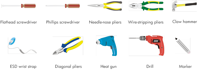
Figure 1 and Figure 2 list the accessories and tools required for installing the router.
Figure 1 Installation accessories

|
|
NOTE: The type of the antenna that comes with the router depends on the router model. |
Figure 2 User-supplied tools and equipment
Pre-installation checklist
Table 4 Pre-installation checklist
|
Item |
Requirements |
Result |
|
|
Installation site |
Ventilation |
· There is a minimum clearance of 10 cm (3.94 in) around the router chassis inlet and outlet vents for heat dissipation. · The installation site ventilation system is adequate. |
|
|
Temperature |
0°C to 40°C (32°F to 104°F) |
|
|
|
Relative humidity |
5% to 90% (noncondensing) |
|
|
|
Cleanliness |
Dust concentration ≤ 3 × 10⁴ particles/m3 |
|
|
|
ESD prevention |
· The equipment and floor are reliably grounded. · The equipment room is dust-proof. · The humidity and temperature are in the acceptable range. · Wear an ESD wrist strap when touching a circuit board. |
|
|
|
EMI prevention |
· Take measures to protect the power system from the power grid system. · Keep the protection ground of the router as far away from the grounding device or lightning protection grounding device as possible. · Keep the router far away from radio transmitters, radar, and high-frequency or high-voltage devices. · Use electromagnetic shielding when necessary. |
|
|
|
Lightning protection |
· The grounding cable of the chassis is grounded reliably. · The grounding terminal of the AC power receptacle is grounded reliably. · A port lightning arrester is installed. (Optional.) · A power lightning arrester is installed. (Optional.) · A signal lightning arrester is installed at the input end of an external signal cable. (Optional.) |
|
|
|
Electricity safety |
· Install an uninterrupted power supply (UPS). · In case of emergency during operation, switch off the external power switch. |
|
|
|
Workbench |
· The workbench is stable. · The workbench is reliably grounded. |
|
|
|
Safety precautions |
· The router is far away from any heat or moisture sources. · The emergency power switch in the equipment room is identified and accessible. |
|
|
|
Tools |
· Installation accessories supplied with the router are ready. · User-supplied tools are ready. |
|
|
|
Reference |
· Documents shipped with the router are available. · Online documents are available. |
|
|
Installing the router
|
|
WARNING! To avoid injury, do not touch bare wires, terminals, or parts with high-voltage hazard signs. |
|
|
IMPORTANT: · The barcode on the router chassis contains product information that must be provided to local sales agent before you return a faulty router for service. · Keep the tamper-proof seal on a mounting screw on the chassis cover intact, and if you want to open the chassis, contact H3C for permission. Otherwise, H3C shall not be liable for any consequence. |
Installation prerequisites
· You have read "Preparing for installation" carefully.
· All requirements in "Preparing for installation" are met.
Installation flow
You can install the router on a workbench or on a wall. Select an installation method according to the installation environment, and follow the installation flowchart shown in Figure 3.
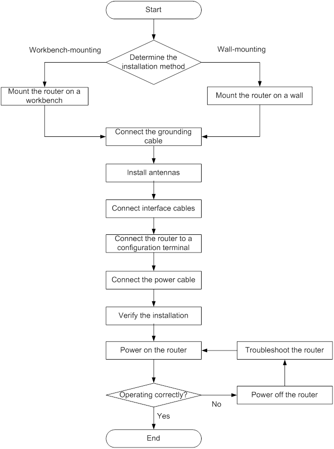
Installing the router
Mounting the router on a workbench
|
|
IMPORTANT: · Reserve a clearance of 10 cm (3.94 in) around the router for heat dissipation. · Do not place heavy objects on the router. |
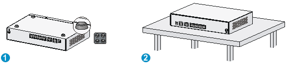
To mount the router on a workbench:
1. Make sure the workbench is clean, stable, and reliably grounded.
2. Place the router upside down on the workbench and attach the rubber feet to the four round holes in the chassis bottom.
3. Place the router on the workbench upside up.
Figure 4 Mounting the router on a workbench
Installing the router on a wall
|
|
CAUTION: Make sure the network interfaces on the router face downwards, and the sides with ventilation openings are perpendicular to the ground, as shown in Figure 5. |
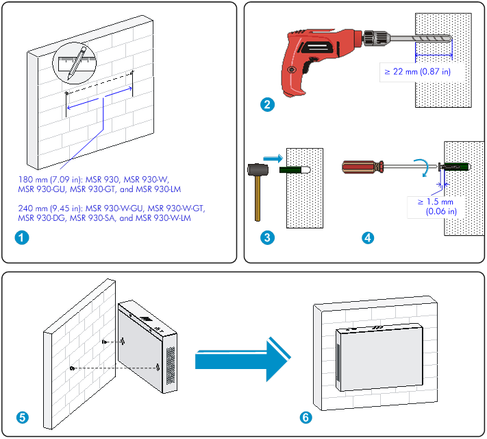
To mount the router on a wall:
1. Mark the locations of the two mounting holes on the wall with the separations listed as follows:
|
Router model |
Separation |
|
MSR 930, MSR 930-GU, MSR 930-GT, MSR 930-W, and MSR 930-LM |
180 mm (7.09 in) |
|
MSR 930-DG, and MSR 930-SA, MSR 930-W-GU, MSR 930-W-GT, and MSR 930-W-LM |
240 mm (9.45 in) |
The holes must be level (on the same horizontal line.)
2. Drill two holes with a minimum depth of 22 mm (0.87 in) at the marked positions.
3. Hammer a screw anchor into each hole.
4. Fasten a screw into each anchor. Do not fasten the screw all the way in. Leave a space of at least 1.5 mm (0.06 in).
5. Align the installation holes at the router rear with the screws on the wall and rest the router on the screws.
Figure 5 Wall-mounting the router
Grounding the router
|
|
WARNING! Connecting the router grounding cable correctly is crucial for protecting the router from lightning and EMI. |
Make sure the grounding resistance is less than 5 ohms.
You can ground the router with a grounding strip or with a grounding conductor buried in the earth ground.
The router provides only a ring terminal but no grounding cable. Purchase a grounding cable if necessary.
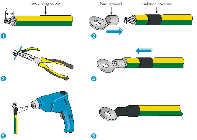
Attaching the ring terminal
1. Cut the grounding cable as appropriate for connecting to the grounding strip.
2. Peel 5 mm (0.20 in) of insulation sheath by using the wire-stripping pliers, and insert the bare metal part through the black insulation covering into the end of the ring terminal.
3. Secure the metal part of the cable to the ring terminal with needle-nose pliers.
4. Cover the joint with the insulation covering, and heat the insulation covering with a heat gun to completely cover the metal part.
Figure 6 Attaching the ring terminal
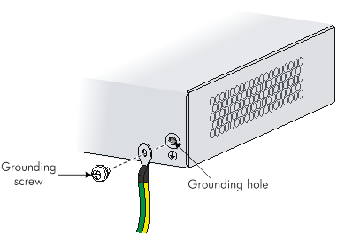
Grounding the router with a grounding strip
1. Remove the grounding screw from the router chassis.
2. Attach the ring terminal of the grounding cable to the grounding screw.
3. Use a screwdriver to fasten the grounding screw.
4. Attach the other end of the grounding cable to the grounding strip.
Figure 7 Connecting the grounding cable to the router
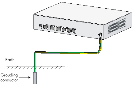
Grounding the router with a grounding conductor buried in the earth ground
If the installation site does not have any grounding strips, but earth ground is available, hammer a 0.5 m (1.64 ft) or longer angle iron or steel tube into the earth to serve as a grounding conductor. See Figure 8.
Figure 8 Grounding the router with a conductor buried in the earth ground
Installing a standard 3G SIM card
|
|
CAUTION: To avoid damage to the holder, do not use extra force when installing the 3G SIM card. |
Standard 3G SIM cards do not support hot swapping.
Select 3G SIM cards based on the router model:
· GU model—WCDMA/GSM SIM card
· GT model—CDMA2000 SIM card
· DG model—CDMA2000 SIM card for SIM1 slot and WCDMA/GSM SIM card for SIM2 slot.
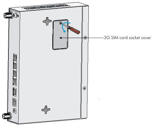
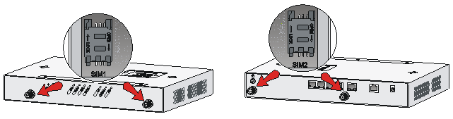
To install a standard 3G SIM card:
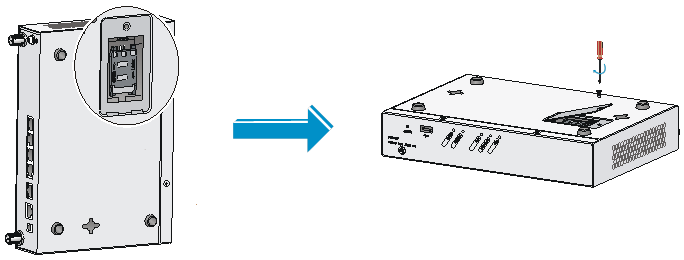
1. Use a screwdriver to remove the screws on the 3G SIM card socket cover on the bottom of the chassis, and remove the cover.
Figure 9 Removing the 3G SIM card socket cover
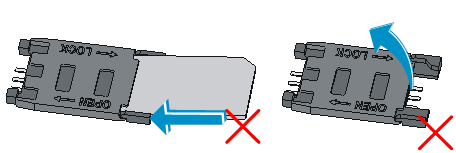
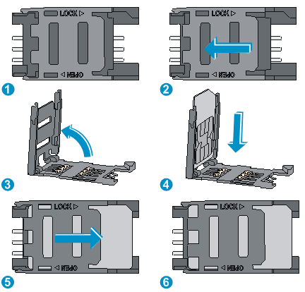
2. Slide the 3G SIM card holder in the direction of the "OPEN" arrow so the holder projects upwards.
Do not directly insert the 3G SIM card into the holder, or lift the holder as shown in Figure 10.
Figure 10 Incorrect installation methods
3. Insert the 3G SIM card along the slide rails to the holder.
4. Push down the holder and slide it in the direction of the "LOCK" arrow to lock the card in position.
Figure 11 Installing the 3G SIM card
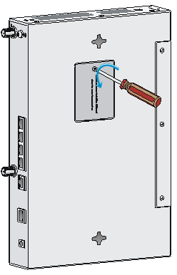
5. Install the socket cover and use a screw to secure it into place.
Figure 12 Installing the cover
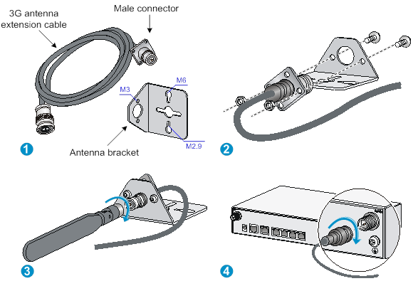
Installing a 3G antenna
|
|
CAUTION: · To connect only one 3G antenna extension cable, connect the cable to the MAIN antenna connector on the router. · To connect two 3G antenna extension cables, connect one cable to the MAIN antenna connector and the other cable to the DIV connector on the router. Make sure the antennas are a minimum of 25 cm (9.84 in) away from each other. · Make sure each antenna is a minimum of 25 cm (9.84 in) away from the router. |
A 3G antenna must be connected to the router through an antenna extension cable. Only one 3G antenna and one antenna extension cable are provided with each 3G module. To install two 3G antennas, purchase one yourself.
To install a 3G antenna:
1. Thread the male connector of the cable through the hole on the bracket, and use screws (from the outside of the bracket) to secure the male connector to the bracket.
2. Change the angle of the antenna orientation from vertical to horizontal.
3. Attach the antenna to the male connector of the cable.
4. Attach the female connector of the cable to the router.
Figure 13 Installing a 3G antenna
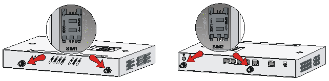
On a dual-3G MSR 930-DG router, the SIM1 (supporting CDMA2000) and SIM2 (supporting WCDMA/GSM) cards are associated with the antenna connectors on the front and rear panels, respectively. Make sure you install the antennas at the correct positions.
Figure 14 SIM card locations on a dual-3G MSR 930-DG router
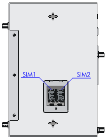
Figure 15 SIM cards and antenna connectors
Installing a standard 4G SIM card
|
|
CAUTION: To avoid damage to the 4G SIM card holder, do not use extra force when installing the 4G SIM card. |
Standard 4G SIM cards do not support hot swapping.
The LM-model router supports both LTE as well as TD-SCDMA and WCDMA.
To install a 4G SIM card:
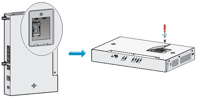
1. Remove the screw of the 4G SIM card socket cover on the router bottom and take off the cover.
Figure 16 Removing the 4G SIM card socket cover
2. Slide the 4G SIM card holder in the direction of the "OPEN" arrow so the holder projects upwards.
Do not insert the 4G SIM card into the card holder or lift the holder directly as shown in Figure 17.
Figure 17 Incorrect installations

3. Insert the 4G SIM card along the slide rails to the holder.
4. Push down the holder and slide the holder in the direction of the "LOCK" arrow to lock the card in position.
Figure 18 Installing the 4G SIM card
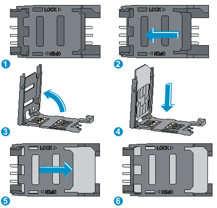
5. Install the 4G SIM card socket cover and use the screw to secure it into place.
Figure 19 Installing the 4G SIM card socket cover
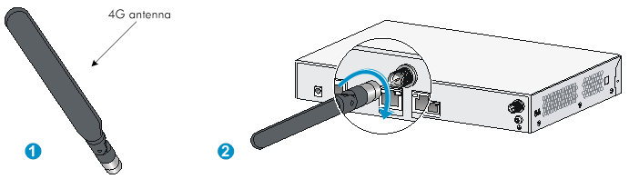
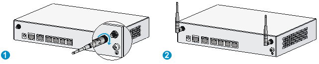
Installing a 4G antenna
For a WLAN & 4G router, the WLAN antenna is located at the front panel, and the 4G antenna is located at the rear panel. Make sure you install the antennas at the correct positions.
Figure 20 Identifying antenna positions

To install a 4G antenna:
1. Change the angle of the antenna orientation from vertical to horizontal.
2. Attach the antenna to the router, as shown in Figure 21. Avoid over-tightening.
Change the antenna orientation to vertical to achieve better signal coverage.
Figure 21 Installing a 4G antenna
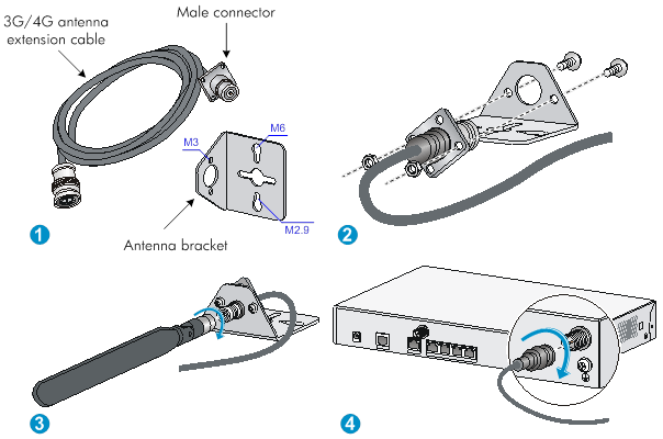
Connecting a 3G/4G antenna extension cable to a 4G router
A 3G/4G antenna extension cable is not provided with the router. To use a 3G/4G antenna extension cable, purchase it separately.
To install a 3G/4G antenna extension cable:
1. Thread the male connector of the cable through the hole on the bracket, and use screws (from behind the bracket) to secure the male connector to the bracket.
2. Change the angle of the antenna orientation from vertical to horizontal.
3. Attach the antenna to the male connector of the cable.
4. Attach the female connector of the cable to the router.
Figure 22 Installing the 3G/4G antenna extension cable to a 4G router
Installing a WLAN antenna
For a WLAN & 3G router or WLAN & 4G router, the WLAN antenna is located at the front panel, and the 3G/4G antenna is located at the rear panel. Make sure you install the antennas at the correct positions.
To install a WLAN antenna:
1. Change the angle of the antenna orientation from vertical to horizontal.
2. Attach the antenna to the antenna port on the router. Avoid over-tightening.
Change the antenna orientation to vertical to achieve better signal coverage.
Figure 23 Installing a WLAN antenna
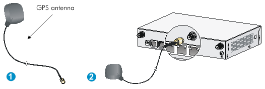
Installing a GPS antenna
1. Attach the male connector of the GPS antenna to the GPS antenna port on the router.
To avoid antenna damage, do not use extra force.
2. Attach the magnetic antenna radome to a metal surface.
Figure 24 Installing a GPS antenna
Connecting interface cables
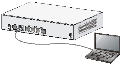
Connecting an Ethernet cable
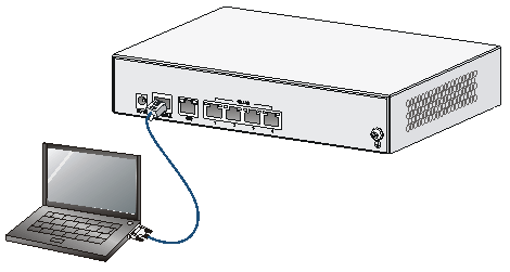
Because fixed Ethernet ports support MDI/MDIX autosensing, you can use either a straight-through cable or a crossover cable for connection.
To connect an Ethernet cable:
1. Connect one end of the cable to an Ethernet port on the router.
2. Connect the other end of the cable to the peer device.
3. Examine the port LED status. For more information, see "LED description."
Figure 25 Connecting the router to a computer
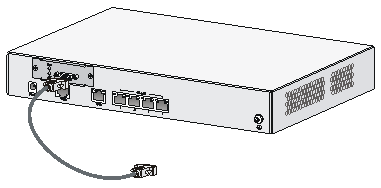
Connecting a synchronous/asynchronous serial port cable
1. Identify the port type of the peer device and choose a serial port cable of correct type.
2. Plug the D28 end of the serial port cable into the D28 port of the SAE interface module.
If the WAN uses DDN line, connect the cable to the port of the CSU/DSU.
3. Examine the LINK LED status. For more information, see "LED description."
Figure 26 Connecting a serial port cable
Connecting a console cable and setting terminal parameters
Connecting a console cable
|
|
CAUTION: When using a console cable to connect a PC to the router, first connect the DB-9 end of the console cable to the PC serial port. Then connect the RJ-45 connector of the console cable to the router console port. |
To connect a console cable, as shown in Figure 27:
1. Select a console terminal. The console terminal can be an ASCII terminal with an RS232 serial port or a PC. (A PC is more commonly used.)
2. Connect the DB-9 connector (female) of the console cable to the RS-232 serial port of the console terminal and the RJ-45 connector to the console port of the router.
Figure 27 Connecting the console cable
Setting terminal parameters
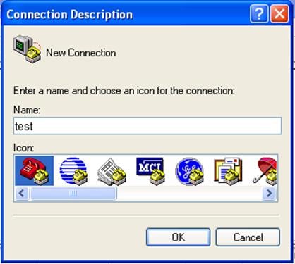
1. Select Start > All Programs > Accessories > Communications > HyperTerminal.
The Connection Description dialog box appears.
2. Enter the name of the new connection in the Name field and click OK.
Figure 28 Connection description
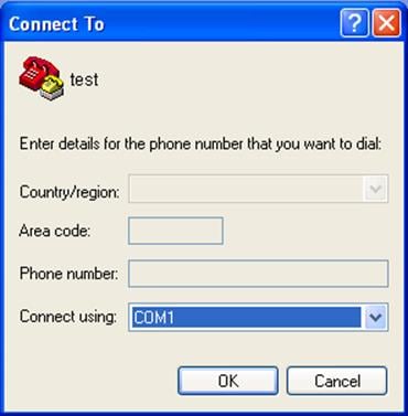
3. Select the serial port to be used from the Connect using list, and click OK.
Figure 29 Setting the serial port used by the HyperTerminal connection
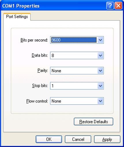
|
|
NOTE: To restore the default settings, click Restore Defaults. |
Figure 30 Setting the serial port parameters
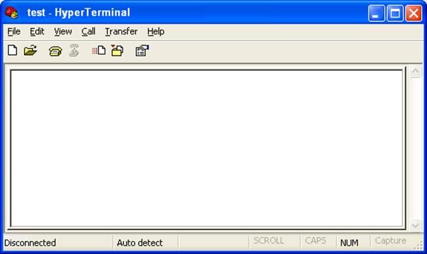
5. Select File > Properties in the HyperTerminal window.
Figure 31 HyperTerminal window
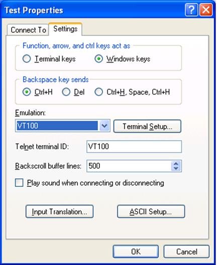
6. On the Settings tab, set the emulation to VT100 or Auto Detect, and click OK.
Figure 32 Setting the terminal emulation parameters
Connecting the power adapter
The router's power adapter converts AC power to DC power, as follows:
· AC rated voltage range: 100 VAC to 240 VAC @ 50 Hz to 60 Hz
· DC rated voltage: 12 VDC
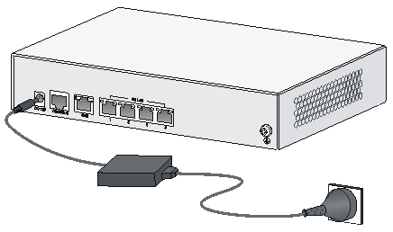
To connect the power adapter, as shown in Figure 33:
1. Make sure the router is reliably grounded. For more information, see "Grounding the router."
2. Using the adapter's AC power cable, connect the power adapter to an AC power source.
3. Connect the DC power cable connector on the power adapter to the DC power receptacle on the router's panel.
Figure 33 Connecting the power adapter
Verifying the installation
After you complete the installation, verify the following information:
· There is enough space around the router for heat dissipation.
· The router is mounted securely on the wall or on a sturdy workbench.
· Antennas, USB devices, and interface modules are installed correctly.
· The router and power module are grounded reliably.
· The power supply meets requirements.
· The router is connected correctly to the console terminal and other devices and parameters are configured correctly on the console terminal.
Before starting up the router, set up the console terminal as described in "Connecting a console cable and setting terminal parameters."
Powering on the router
|
|
WARNING! Before powering on the router, locate the power source switch so that you can cut off power promptly in case of an emergency. |
· Switch on the power source.
· Turn on the power switch on the router.
Displaying boot information
After power-on, the router initializes its memory, and then runs the extended BootWare. The console terminal screen displays the following information:
System is starting...
Booting Normal Extend BootWare
The Extend BootWare is self-decompressing...........................Done!
****************************************************************************
* *
* H3C MSR930 BootWare, Version 2.01 *
* *
****************************************************************************
Copyright (c) 2004-2017 New H3C Technologies Co., Ltd.
Compiled Date : Aug 19 2012
CPU Type : P1010
CPU L1 Cache : 32KB
CPU L2 Cache : 256KB
CPU Clock Speed : 533MHz
Memory Type : DDR3 SDRAM
Memory Size : 256MB
Memory Speed : 667MHz
BootWare Size : 1024KB
Flash Size : 128MB
CPLD Version : 130.0
PCB Version : 3.0
BootWare Validating...
Press Ctrl+B to enter extended boot menu...
Starting to get the main application file--flash:/mainmsr930.bin!...........
............................................................................
............................................................................
...
The main application file is self-decompressing.............................
.......Done!
System application is starting
..........................................
User interface aux0 is available.
Press ENTER to get started.
Press Enter and the system displays the following prompt:
<Sysname>
This prompt indicates that the router has entered user view and is ready to configure.
Checking after power-on
After powering on the router, verify the following items:
· The LEDs on the front panel are normal, as described in "LED description."
· The console terminal displays information correctly. You can see the startup window on the local console terminal. For more information, see "Displaying boot information."
· After completing the POST, the system prompts you to press Enter. When the command line prompt appears, the router is ready to configure.
Configuring basic settings for the router
After the router is powered on for the first time, configure basic settings for the router. For more information, see H3C MSR Series Routers Configuration Guides (V5) and H3C MSR Series Routers Command References (V5).
Troubleshooting
|
|
IMPORTANT: · The barcode on the router chassis contains product information that must be provided to local sales agent before you return a faulty router for service. · Keep the tamper-proof seal on a mounting screw on the chassis cover intact, and if you want to open the chassis, contact H3C for permission. Otherwise, H3C shall not be liable for any consequence. |
Power supply failure
Symptom
The router cannot be powered on and LEDs on the front panel are off.
Solution
To resolve the issue:
1. Power off the router.
2. Verify that the router's power cables are connected firmly.
3. Verify that the power source is operating correctly.
4. Determine if the power cable is damaged.
5. If the issue persists, contact H3C Support.
System configuration problems
If the configuration environment setup is correct, the console terminal displays boot information when the router is powered on. If the setup is incorrect, the console terminal displays nothing or garbled text.
No terminal display
Symptom
The console terminal displays nothing when the router is powered on.
Solution
To resolve the issue:
1. Verify that the power supply system is operating correctly.
2. Verify that the console cable is connected correctly.
3. Verify that the console cable is connected to the serial port of the console terminal.
4. Verify that the following terminal settings are correct:
¡ Bits per second—9600.
¡ Data bits—8.
¡ Parity—None.
¡ Stop bits—1.
¡ Flow control—None.
¡ Terminal Emulation—VT100.
5. Verify that the console cable is operating correctly.
6. If the issue persists, contact H3C Support.
Garbled terminal display
Symptom
Terminal display is garbled.
Solution
To resolve the issue:
1. Make sure the Data bits field for the console terminal is set to 8. If the Data bits field is set to 5 or 6, the console terminal will display garbled characters.
2. If the issue persists, contact H3C Support.
No response from the serial port
Symptom
The serial port gives no response.
Solution
To resolve the issue:
1. Verify that the serial cable is in good condition and the serial port settings are correct.
2. If the issue persists, contact H3C Support.
3G/4G SIM card and 3G/4G antenna failures
Symptom
The LEDs on the front panel indicate that the 3G/4G SIM card and 3G/4G antenna are operating incorrectly after the 3G/4G SIM card and 3G/4G antenna are installed on the router and the router is powered on.
Solution
To resolve the issue:
1. Verify that the 3G/4G SIM card has been correctly installed and makes good contact with the card socket.
2. Verify that the 3G/4G SIM card matches the built-in 3G/4G module.
3. Verify that the 3G/4G antenna is correctly installed.
4. Verify that the 3G/4G SIM card, card socket, and 3G/4G antenna are in good condition.
5. Verify that the network provided by NSP is running correctly.
6. If the issue persists, contact H3C Support.
Restoring the factory settings
Scenario 1
Symptom
When you replace the router, the router password is lost. As a result, you cannot log in to the router and do not know the router configuration.
Solution
Because the router is replaced, you do not need to save the configuration of the router. In this case, you can press the Reset button for more than 4 seconds to reboot the router and restore the factory settings. Then, you can use the username and password shipped with the router to log in to the router.
When the router configuration must be saved and you have a console cable, you can log in to the router from the BootWare menu.
Scenario 2
Symptom
After the configuration is modified, the network connectivity is lost. When you check the configuration, the configuration is very complicated and it is hard to locate the errors. In this case, you must configure the router again.
Solution
If you have not saved any configuration, you can reboot the router by pressing the Reset button for a short time or power off the router.
If you have saved the configuration, delete the configuration file at the CLI, and press the Reset button to restore the factory settings.
Scenario 3
Symptom
The router crashes.
Solution
Press the Reset button for a short time to reboot the router.
Reset button usage guidelines
An MSR 930 router provides the Reset button. You can use the button to reboot the system or restore the factory settings.
· Press the Reset button for a short time to reboot the router.
· Press the Reset button for more than 4 seconds to reboot the router and restore the factory settings.
Appendix A Chassis views and technical specifications
Chassis views
The figures in this appendix are for illustration only.
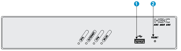
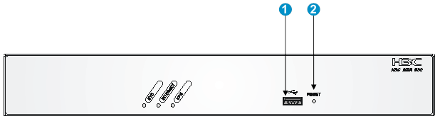
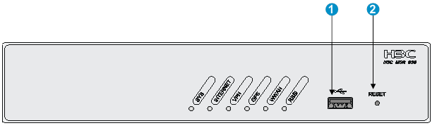
MSR 930
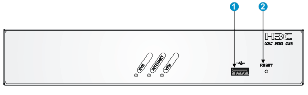
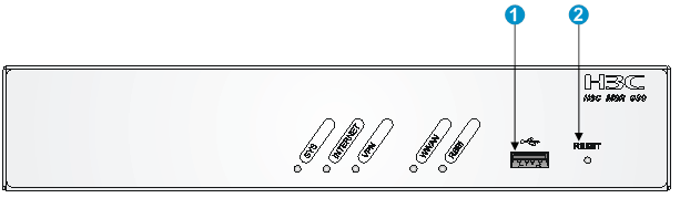
Figure 34 MSR 930 front view
|
(1) USB port |
(2) Reset button (RESET) |
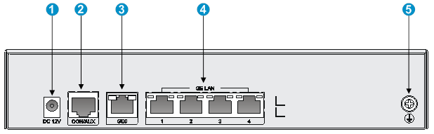
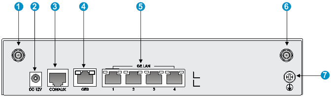
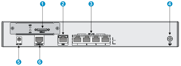
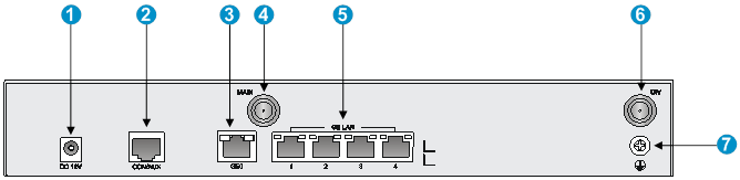
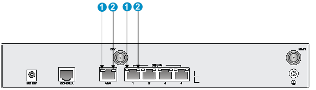
Figure 35 MSR-930 rear view
|
(1) Power adapter receptacle |
(2) Console/AUX port |
(3) Gigabit Ethernet WAN port (GE0) |
|
(4) Gigabit Ethernet LAN ports (GE1 to GE4) |
(5) Grounding screw |
|
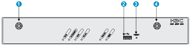
MSR 930-GU
Figure 36 MSR 930-GU front view
|
(1) USB port |
(2) Reset button (RESET) |
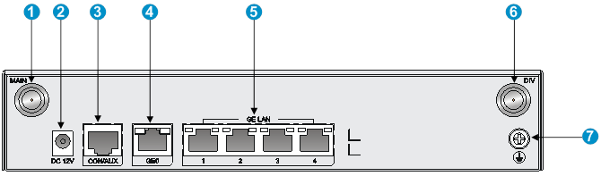
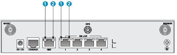
Figure 37 MSR 930-GU rear view
|
(1) 3G antenna main connector (MAIN) |
(2) Power adapter receptacle |
(3) Console/AUX port (CON/AUX) |
|
(4) Gigabit Ethernet WAN port (GE0) |
(5) Gigabit Ethernet LAN ports (GE1 to GE4 ) |
(6) 3G antenna auxiliary connector (DIV) |
|
(7) Grounding screw |
|
|
MSR 930-GT
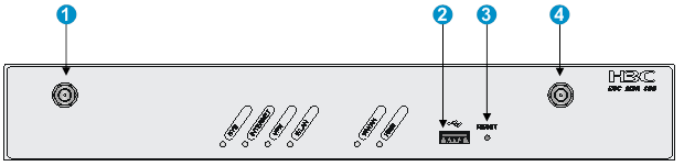
Figure 38 MSR 930-GT front view

|
(1) USB port |
(2) Reset button (RESET) |
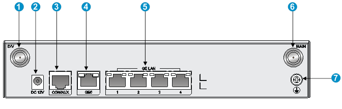
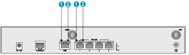
Figure 39 MSR 930-GT rear view
|
(1) 3G antenna auxiliary connector (DIV) |
(2) Power adapter receptacle |
(3) Console/AUX port (CON/AUX) |
|
(4) Gigabit Ethernet WAN port (GE0) |
(5) Gigabit Ethernet LAN ports (GE1 to GE4) |
(6) 3G antenna main connector (MAIN) |
|
(7) Grounding screw |
|
|
MSR 930-W
Figure 40 MSR 930-W front view
|
(1) USB port |
(2) Reset button (RESET) |
Figure 41 MSR 930-W rear view
|
(1) WLAN antenna port |
(2) Power adapter receptacle |
(3) Console/AUX port (CON/AUX) |
|
(4) Gigabit Ethernet WAN port (GE0) |
(5) Gigabit Ethernet LAN ports (GE1 to GE4) |
(6) WLAN antenna port |
|
(7) Grounding screw |
||
MSR 930-DG
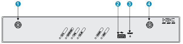
Figure 42 MSR 930-DG front view
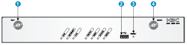
|
(1) 3G antenna auxiliary connector (DIV1) |
(2) USB port |
|
(3) Reset button (RESET) |
(4) 3G antenna main connector (MAIN1) |
Figure 43 MSR 930-DG rear view
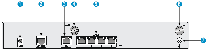
|
(1) Power adapter receptacle |
(2) Console/AUX port (CON/AUX) |
(3) Gigabit Ethernet WAN port (GE0) |
|
(4) 3G antenna main connector (MAIN2) |
(5) Gigabit Ethernet LAN ports (GE1 to GE4) |
(6) 3G antenna auxiliary connector (DIV2) |
|
(7) Grounding screw |
|
|
MSR 930-SA
Figure 44 MSR 930-SA front view
|
(1) USB port |
(2) Reset button (RESET) |
Figure 45 MSR 930-SA rear view
|
(1) Synchronous/asynchronous serial port (Serial0) |
(2) Gigabit Ethernet WAN port (GE0) |
(3) Gigabit Ethernet LAN ports (GE1 to GE4) |
|
(4) Grounding screw |
(5) Power adapter receptacle |
(6) Console/AUX port (CON/AUX) |
MSR 930-W-GU
Figure 46 MSR 930-W-GU front view
|
(1) WLAN antenna port |
(2) USB port |
|
(3) Reset button (RESET) |
(4) WLAN antenna port |
Figure 47 MSR 930-W-GU rear view

|
(1) Power adapter receptacle |
(2) Console/AUX port (CON/AUX) |
(3) Gigabit Ethernet WAN port (GE0) |
|
(4) 3G antenna main connector (MAIN) |
(5) Gigabit Ethernet LAN ports (GE1 to GE4) |
(6) 3G antenna auxiliary connector (DIV) |
|
(7) Grounding screw |
|
|
MSR 930-W-GT
Figure 48 MSR 930-W-GT front view
|
(1) WLAN antenna port |
(2) USB port |
|
(3) Reset button (RESET) |
(4) WLAN antenna port |
Figure 49 MSR 930-W-GT rear view

|
(1) Power adapter receptacle |
(2) Console/AUX port (CON/AUX) |
(3) Gigabit Ethernet WAN port (GE0) |
|
(4) 3G antenna main connector (MAIN) |
(5) Gigabit Ethernet LAN ports (GE1 to GE4) |
(6) 3G antenna auxiliary connector (DIV) |
|
(7) Grounding screw |
|
|
MSR 930-LM
Figure 50 MSR 930-LM front view
|
(1) USB port |
(2) Reset button (RESET) |
Figure 51 MSR 930-LM rear view

|
(1) 4G antenna port (M1) |
(2) Gigabit Ethernet WAN port (GE0) |
(3) Gigabit Ethernet LAN ports (GE1 to GE4) |
|
(4) GPS antenna port |
(5) 4G antenna port (M0) |
(6) Grounding screw |
|
(7) Power adapter receptacle |
(8) Console/AUX port (CON/AUX) |
|
MSR 930-W-LM
Figure 52 MSR 930-W-LM front view
|
(1) WLAN antenna port |
(2) USB port |
|
(3) Reset button (RESET) |
(4) WLAN antenna port |
Figure 53 MSR 930-W-LM rear view
|
(1) Power adapter receptacle |
(2) Console/AUX port (CON/AUX) |
(3) Gigabit Ethernet WAN port (GE0) |
|
(4) 4G antenna port |
(5) Gigabit Ethernet LAN ports (GE1 to GE4) |
(6) 4G antenna port |
|
(7) Grounding screw |
|
|
Technical specifications
|
Item |
MSR 930 |
MSR 930-GU |
MSR 930-GT |
MSR 930-W |
MSR 930-LM |
|
Console/AUX port |
1 |
1 |
1 |
1 |
1 |
|
USB port |
1 |
1 |
1 |
1 |
1 |
|
GE WAN port |
1 |
1 |
1 |
1 |
1 |
|
GE LAN port |
4 |
4 |
4 |
4 |
4 |
|
Serial port |
N/A |
N/A |
N/A |
N/A |
N/A |
|
Built-in 3G/4G module |
N/A |
WCDMA (China Unicom) |
CDMA2000 (China Telecom) |
N/A |
LTE FDD (China Unicom) and LTE TDD (China Mobile) |
|
WLAN module |
N/A |
N/A |
N/A |
1 |
N/A |
|
GPS module |
N/A |
N/A |
N/A |
N/A |
1 |
|
Memory |
256 MB DDR III |
256 MB DDR III |
256 MB DDR III |
256 MB DDR III |
256 MB DDR III |
|
Flash |
128 MB |
128 MB |
128 MB |
128 MB |
128 MB |
|
Dimensions (H × W × D) (excluding rubber feet and mounting brackets) |
43.6 x 230 x 160 mm (1.72 x 9.06 x 6.30 in) |
43.6 x 230 x 160 mm (1.72 x 9.06 x 6.30 in) |
43.6 x 230 x 160 mm (1.72 x 9.06 x 6.30 in) |
43.6 x 230 x 160 mm (1.72 x 9.06 x 6.30 in) |
43.6 x 230 x 160 mm (1.72 x 9.06 x 6.30 in) |
|
Weight |
1.0 kg (2.20 lb) |
1.1 kg (2.43 lb) |
1.1 kg (2.43 lb) |
1.1 kg (2.43 lb) |
1.1 kg (2.43 lb) |
|
AC power supply |
Rated input voltage: 100 VAC to 240 VAC @ 50 Hz or 60 Hz |
Rated input voltage: 100 VAC to 240 VAC @ 50 Hz or 60 Hz |
Rated input voltage: 100 VAC to 240 VAC @ 50 Hz or 60 Hz |
Rated input voltage: 100 VAC to 240 VAC @ 50 Hz or 60 Hz |
Rated input voltage: 100 VAC to 240 VAC @ 50 Hz or 60 Hz |
|
Max. AC power |
24 W |
24 W |
24 W |
24 W |
24 W |
|
Operating temperature |
0°C to 40°C (32°F to 104°F) |
0°C to 40°C (32°F to 104°F) |
0°C to 40°C (32°F to 104°F) |
0°C to 40°C (32°F to 104°F) |
0°C to 40°C (32°F to 104°F) |
|
Relative humidity (non-condensing) |
5% to 90% |
5% to 90% |
5% to 90% |
5% to 90% |
5% to 90% |
|
Item |
MSR 930-DG |
MSR 930-SA |
MSR 930-W-GU |
MSR 930-W-GT |
MSR 930-W-LM |
|
Console/AUX port |
1 |
1 |
1 |
1 |
1 |
|
USB port |
1 |
1 |
1 |
1 |
1 |
|
GE WAN port |
1 |
1 |
1 |
1 |
1 |
|
GE LAN port |
4 |
4 |
4 |
4 |
4 |
|
Serial port |
N/A |
1 |
N/A |
N/A |
N/A |
|
Built-in 3G/4G module |
CDMA2000 (China Telecom) and WCDMA (China Unicom) |
N/A |
WCDMA (China Unicom) |
CDMA2000 (China Telecom) |
LTE FDD (China Unicom) and LTE TDD (China Mobile) |
|
WLAN module |
N/A |
N/A |
1 |
1 |
1 |
|
GPS module |
N/A |
N/A |
N/A |
N/A |
N/A |
|
Memory |
256 MB DDR III |
256 MB DDR III |
256 MB DDR III |
256 MB DDR III |
256 MB DDR III |
|
Flash |
128 MB |
128 MB |
128 MB |
128 MB |
128 MB |
|
Dimensions (H × W × D) (excluding rubber feet and mounting brackets) |
44.2 × 300 × 200 mm (1.74 × 11.81 × 7.87 in) |
44.2 × 300 × 200 mm (1.74 × 11.81 × 7.87 in) |
44.2 × 300 × 200 mm (1.74 × 11.81 × 7.87 in) |
44.2 × 300 × 200 mm (1.74 × 11.81 × 7.87 in) |
44.2 × 300 × 200 mm (1.74 × 11.81 × 7.87 in) |
|
Weight |
1.6 kg (3.53 lb) |
1.6 kg (3.53 lb) |
1.6 kg (3.53 lb) |
1.6 kg (3.53 lb) |
1.6 kg (3.53 lb) |
|
AC power supply |
Rated input voltage: 100 VAC to 240 VAC @ 50 Hz or 60 Hz |
Rated input voltage: 100 VAC to 240 VAC @ 50 Hz or 60 Hz |
Rated input voltage: 100 VAC to 240 VAC @ 50 Hz or 60 Hz |
Rated input voltage: 100 VAC to 240 VAC @ 50 Hz or 60 Hz |
Rated input voltage: 100 VAC to 240 VAC @ 50 Hz or 60 Hz |
|
Max. AC power |
24 W |
24 W |
24 W |
24 W |
24 W |
|
Operating temperature |
0°C to 40°C (32°F to 104°F) |
0°C to 40°C (32°F to 104°F) |
0°C to 40°C (32°F to 104°F) |
0°C to 40°C (32°F to 104°F) |
0°C to 40°C (32°F to 104°F) |
|
Relative humidity (non-condensing) |
5% to 90% |
5% to 90% |
5% to 90% |
5% to 90% |
5% to 90% |
4G antenna specifications
|
Item |
Specification |
|
Frequency range |
698-960 MHz/1710-2700 MHz |
|
Voltage Standing Wave Ratio (VSWR) |
< 2.5 |
|
Input impedance |
50 ohms |
|
Gain |
2 dBi |
|
Max power consumption |
5 W |
|
Input interface |
TNC male |
|
Length |
214 mm (8.43 in) |
|
Color |
Black |
|
Weight |
50 g (0.11 lb, estimated) |
|
Operating temperature |
–40°C to +85°C (–40°F to +185°F) |
3G antenna specifications
Table 5 3G antenna specifications
|
Item |
Specification |
|
Frequency range |
806-960 MHz/1710-2170 MHz |
|
Voltage standing wave ratio (VSWR) |
< 2.5 |
|
Input impedance |
50 ohms |
|
Gain |
0 dBi |
|
Max power consumption |
25 W |
|
Input interface |
TNC male |
|
Length |
254 mm (10 in) |
|
Color |
Gray |
|
Weight |
45 g (0.10 lb) |
|
Operating temperature |
–30°C to +70°C (–22°F to +158°F) |
Table 6 WLAN antenna specifications
|
Item |
Specification |
|
Frequency range |
2.4 GHz to 2.5 GHz |
|
Voltage standing wave ratio (VSWR) |
1.92:1 |
|
Input impedance |
50 ohms |
|
Gain |
2 dBi |
|
Max power consumption |
1 W |
|
Input interface |
RSMA |
|
Length |
115 mm (4.53 in) |
|
Color |
Black |
|
Weight |
25 g (0.06 lb) |
|
Operating temperature |
–10°C to +60°C (14°F to 140°F) |
Appendix B LEDs
LEDs
MSR 930
Figure 54 Front panel LEDs

|
(1) System status LED (SYS) |
(2) Network status LED (INTERNET) |
|
(3) VPN status LED (VPN) |
|
Figure 55 Rear panel LEDs
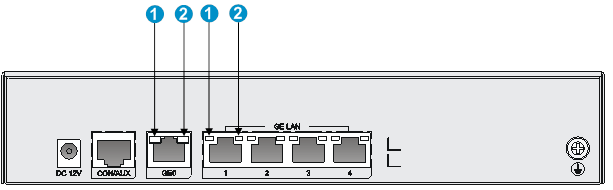
|
(1) GE port status LED (yellow) |
(2) GE port status LED (green) |
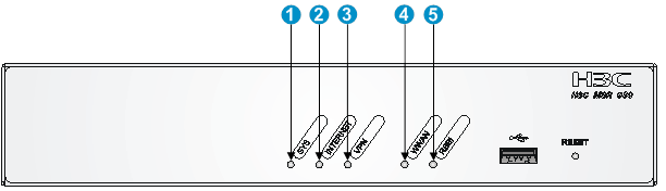
MSR 930-GU
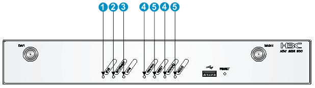
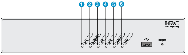
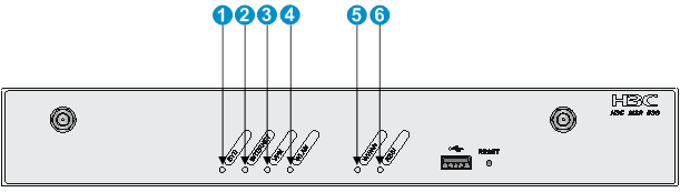
Figure 56 Front panel LEDs

|
(1) System status LED (SYS) |
(2) Network status LED (INTERNET) |
(3) VPN status LED (VPN) |
|
(4) 3G status LED (WWAN) |
(5) Received 3G signal strength indication LED (RSSI) |
|
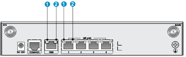
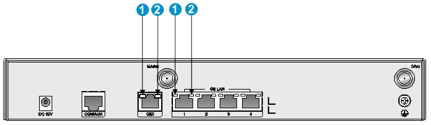
Figure 57 Rear panel LEDs

|
(1) GE port status LED (yellow) |
(2) GE port status LED (green) |
MSR 930-GT
Figure 58 Front panel LEDs
|
(1) System status LED (SYS) |
(2) Network status LED (INTERNET) |
(3) VPN status LED (VPN) |
|
(4) 3G status LED (WWAN) |
(5) Received 3G signal strength indication LED (RSSI) |
|
Figure 59 Rear panel LEDs
|
(1) GE port status LED (yellow) |
(2) GE port status LED (green) |
MSR 930-W
Figure 60 Front panel LEDs
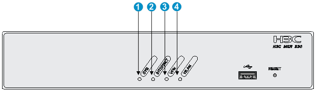
|
(1) System status LED (SYS) |
(2) Network status LED (INTERNET) |
(3) VPN status LED (VPN) |
|
(4) WLAN status LED (WLAN) |
|
|
Figure 61 Rear panel LEDs
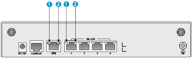
|
(1) GE port status LED (yellow) |
(2) GE port status LED (green) |
MSR 930-DG
Figure 62 Front panel LEDs
|
(1) System status LED (SYS) |
(2) Network status LED (INTERNET) |
(3) VPN status LED (VPN) |
|
(4) 3G status LED (WWAN) |
(5) Received 3G signal strength indication LED (RSSI) |
|
Figure 63 Rear panel LEDs
|
(1) GE port status LED (yellow) |
(2) GE port status LED (green) |
MSR 930-SA
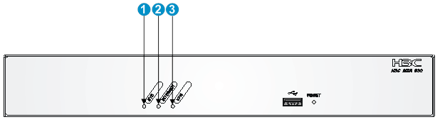
Figure 64 Front panel LEDs
|
(1) System status LED (SYS) |
(2) Network status LED (INTERNET) |
(3) VPN status LED (VPN) |
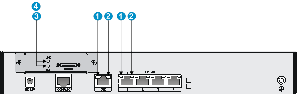
Figure 65 Rear panel LEDs
|
(1) GE port status LED (yellow) |
(2) GE port status LED (green) |
|
(3) Serial port data transmission status LED (ACT) |
(4) Serial port link status LED (LINK) |
MSR 930-W-GU
Figure 66 Front panel LEDs
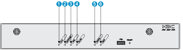
|
(1) System status LED (SYS) |
(2) Network status LED (INTERNET) |
(3) VPN status LED (VPN) |
|
(4) WLAN status LED (WLAN) |
(5) 3G status LED (WWAN) |
(6) Received 3G signal strength indication LED (RSSI) |
Figure 67 Rear panel LEDs

|
(1) GE port status LED (yellow) |
(2) GE port status LED (green) |
MSR 930-W-GT
Figure 68 Front panel LEDs
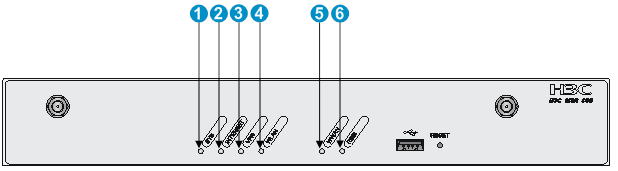
|
(1) System status LED (SYS) |
(2) Network status LED (INTERNET) |
(3) VPN status LED (VPN) |
|
(4) WLAN status LED (WLAN) |
(5) 3G status LED (WWAN) |
(6) Received 3G signal strength indication LED (RSSI) |
Figure 69 Rear panel LEDs
|
(1) GE port status LED (yellow) |
(2) GE port status LED (green) |
MSR 930-LM
Figure 70 Front panel LEDs
|
(1) System status LED (SYS) |
(2) Network status LED (INTERNET) |
(3) VPN status LED (VPN) |
|
(4) GPS status LED (GPS) |
(5) 4G status LED (WWAN) |
(6) Received 4G signal strength indication LED (RSSI) |
Figure 71 Rear panel LEDs
|
(1) GE port status LED (yellow) |
(2) GE port status LED (green) |
MSR 930-W-LM
Figure 72 Front panel LEDs
|
(1) System status LED (SYS) |
(2) Network status LED (INTERNET) |
(3) VPN status LED (VPN) |
|
(4) WLAN status LED (WLAN) |
(5) 4G status LED (WWAN) |
(6) Received 4G signal strength indication LED (RSSI) |
Figure 73 Rear panel LEDs
|
(1) GE port status LED (yellow) |
(2) GE port status LED (green) |
LED description
|
LED |
Location |
Status |
Description |
|
System status LED (SYS) |
Front panel |
Off |
No power input, or exceptions have occurred. |
|
Steady green |
The SDRAM is performing self-test. |
||
|
Flashing green (8 Hz) |
The system software image is being copied and decompressed. |
||
|
Flashing green (1 Hz) |
Comware has started with the configuration file and the router has booted up. |
||
|
Flashing yellow (1 Hz) |
The SDRAM has failed the self-test. |
||
|
Flashing yellow (8 Hz) |
The extended segment does not exist. |
||
|
Steady yellow |
The system software image does not exist. |
||
|
Network status LED (INTERNET) |
Front panel |
Off |
No PPP link is present. |
|
Steady on |
A minimum of one PPP link is present. |
||
|
VPN status LED (VPN) |
Front panel |
Off |
No IPSec VPN tunnel is present. |
|
Steady on |
A minimum of one IPSec VPN tunnel is present. |
||
|
3G status LED (WWAN) |
Front panel |
Off |
No link is present or no wireless network is available. |
|
Steady green |
The router has been connected to the wireless network and is operating in 3G mode. |
||
|
Flashing green (8 Hz) |
Data is being received or transmitted. The router is operating in 3G mode. |
||
|
Steady yellow |
The router has been connected to the wireless network and is operating in 2G mode. |
||
|
Flashing yellow (8 Hz) |
Data is being received or transmitted. The router is operating in 2G mode. |
||
|
Received 3G signal strength indication LED (RSSI) |
Front panel |
Off |
Weak or no signal. |
|
Steady green |
Strong signal. |
||
|
Flashing green (8 Hz) |
Middle or low signal. |
||
|
4G status LED (WWAN) |
Front panel |
Off |
No link is present or the router is operating in 2G mode. |
|
Steady green |
The router has been connected to the wireless network and is operating in 4G mode. |
||
|
Flashing green (8 Hz) |
Data is being received or transmitted. The router is operating in 4G mode. |
||
|
Steady yellow |
The router has been connected to the wireless network and is operating in 3G mode. |
||
|
Flashing yellow (8 Hz) |
Data is being received or transmitted. The router is operating in 3G mode. |
||
|
Received 4G signal strength indication LED (RSSI) |
Front panel |
Off |
Weak or no signal. |
|
Steady green |
Strong signal. |
||
|
Flashing green (8 Hz) |
Middle or low signal. |
||
|
WLAN status LED (WLAN) |
Front panel |
Off |
No link is present. |
|
Steady green |
The radio interface is connected. |
||
|
Flashing green |
Data is being received or transmitted. |
||
|
GE port status LED |
Rear panel |
Off |
No link is present. |
|
Steady green |
A 1000 Mbps link is present. |
||
|
Flashing green |
Data is being received or transmitted at 1000 Mbps. |
||
|
Steady yellow |
A 10/100 Mbps link is present. |
||
|
Flashing yellow |
Data is being received or transmitted at 10/100 Mbps. |
||
|
Serial port data transmission status LED (ACT) |
Rear panel |
Off |
No data is being received or transmitted. |
|
Flashing green |
Data is being received or transmitted. |
||
|
Serial port link status LED (LINK) |
Rear panel |
Off |
No link is present. |
|
Steady green |
A link is present. |
