- Table of Contents
- Related Documents
-
| Title | Size | Download |
|---|---|---|
| 01-MPLS SR configuration | 411.89 KB |
Dynamic SID allocation through an IGP
Label forwarding entry installation based on SIDs
IP traffic forwarding over SRLSPs tasks at a glance
MPLS TE traffic forwarding over static SRLSPs tasks at a glance
Configuring a static adjacency segment
Configuring a static prefix segment
Configuring IGP-based SID advertisement
IGP-based SID advertisement tasks at a glance
Prerequisites for configuring IGP-based SID advertisement
Configuring the IGP to support MPLS SR
Enabling MPLS SR adjacency label allocation for the IGP
Configuring the device to prefer SRLSPs in traffic forwarding
Configuring an MPLS TE tunnel over a static SRLSP
Binding a static SRLSP to an MPLS TE tunnel interface
Configuring MPLS SR and LDP interworking·
Restrictions and guidelines for MPLS SR and LDP interworking
Prerequisites for MPLS SR and LDP internetworking
Display and maintenance commands for MPLS SR
MPLS SR configuration examples
Example: Configuring MPLS SR based on static segments
Example: Configuring MPLS SR based on ISIS-advertised SIDs
Example: Configuring MPLS SR based on OSPF-advertised SIDs
Example: Configuring MPLS SR over LDP
Configuring MPLS SR
About MPLS SR
Segment Routing (SR) is a source routing technology. The source node selects a path for the packets, and then encodes the path in the packet header as an ordered list of segments. Each segment is identified by the segment identifier (SID). The SR nodes along the path forward the packets based on the SIDs in the packets. Only the source node needs to maintain the path status.
SR can operate with MPLS. In an MPLS network, SR uses MPLS labels as SIDs to forward packets on an LSP.
MPLS SR characteristics
MPLS SR has the following characteristics:
· MPLS SR forwards packets based on the existing MPLS infrastructure. No infrastructure modifications are needed to implement SR on an MPLS network. For more information about the MPLS infrastructure, see MPLS basics configuration in MPLS Configuration Guide.
· MPLS SR expands and optimizes existing IGPs and BGP and uses the IGPs and BGP to distribute labels.
· MPLS SR implements network features such as MPLS TE in a simpler way, eliminating issues such as heavy and complicated routing protocol deployment.
Basic concepts
· SR node—A node enabled with the MPLS SR feature. The ingress node (source node) adds labels to packets. The transit nodes forward packets based on labels. The egress node removes labels and forwards packets to the destination networks. SR nodes form an SR domain.
· Segment—An instruction an SR node executes on the incoming packet.
· SID—Segment ID, which is MPLS label in MPLS SR.
· Segment type—The following types of segments are available:
? Prefix segment—SIDs are assigned to nodes based on destination address prefix. The nodes create prefix-specific forwarding entries.
? Adjacency segment—SIDs are assigned to nodes based on adjacency.
· SRLSP—Segment routing label switched path, an LSP along which SR uses MPLS labels as SIDs to forward packets.
· SRGB—Segment routing global block, a range of global labels dedicated for MPLS SR prefix SIDs. Different nodes can have different SRGBs. The minimum label value of an SRGB label range is referred to as the base value of the SRGB. Labels 16000 through 24000 are reserved for SRGBs.
How MPLS SR works
MPLS SR involves the following steps:
1. Label allocation for all nodes and links along the packet forwarding paths.
The following methods are available:
? Static segment configuration
? Dynamic SID allocation through an IGP
2. Label forwarding entry installation based on SIDs. All MPLS SR devices in the SR domain use the allocated labels to create label forwarding entries.
3. SRLSP setup. You can manually configure SRLSPs, or use an IGP, BGP, or a controller to dynamically create SRLSPs.
4. SRLSP and MPLS TE tunnel binding. After you bind an SRLSP to an MPLS TE tunnel, the MPLS TE tunnel uses the SRLSP for packet forwarding.
When the ingress node of an SRLSP receives a packet, it adds labels to the packet and forwards the packet to the egress node through the SRLSP. After receiving a packet from the SRLSP, the egress node removes the label and forwards the packet based on the routing table.
You can bind a higher layer application (for example, MPLS TE) to an SRLSP to forward traffic of the application through the SRLSP.
Static segment configuration
Static MPLS SR provides the following methods for configuring static segments for a destination:
· Prefix segment method—Manually configure the incoming label, outgoing label, and next hop for the destination address prefix on each SR node.
· Adjacency segment method—Manually configure the incoming label and next hop for the adjacency to the neighbor on each SR node.
Dynamic SID allocation through an IGP
MPLS SR expands IGP protocols such as IS-IS and OSPF to advertise SIDs in IGP protocol packets. MPLS SR provides the following methods for dynamically allocating and advertising SIDs:
· Prefix SID—After you configure an SID for the loopback address on each SR node, the SIDs uniquely identify the SR nodes. All SR nodes in the SR domain use an IGP to advertise their own prefix SIDs. After receiving advertised prefix SIDs, each SR node calculates the prefix SIDs to the advertisers.
The prefix SID advertisement can be one of the following types:
? Absolute value advertisement—Each SR node advertises the prefix SID absolute value and the SRGB.
? Index value advertisement—Each SR node advertises the prefix SID index and the SRGB.
Each SR node is assigned a globally unique index value for the node's prefix. The prefix SID an SR node allocates for a prefix equals the SRBG base of the SR node plus the index for that prefix.
|
|
NOTE: The device supports only the index value advertisement in the current software release. |
· Adjacency SID—Each SR node with adjacency SID allocation enabled allocates SIDs for the IGP adjacencies, that is, the links to its IGP neighbors, and uses the SIDs to identify the links.
Label forwarding entry installation based on SIDs
Label forwarding entry installation based on IGP prefix SIDs
Label forwarding entries based on prefix SIDs can be static or dynamic.
· Static label forwarding entries—The device creates local label forwarding entries based on manually configured incoming labels, outgoing labels, and next hops.
· Dynamic label forwarding entries—The device uses the IGP to flood in the SR domain the local SRGB and the index of the prefix SID for the local loopback interface. Based on the flooded information, the other devices in the domain calculates their local label forwarding entries by using the following rules:
? Incoming label = Local SRGB base value + Index
? Outgoing label = SRGB base value of the next hop + Index
Figure 1 Creating label forwarding entries based on IGP prefix SIDs
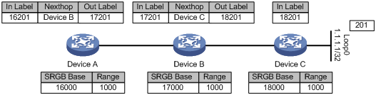
Figure 1 shows how dynamic label forwarding entries are created. After you assign index value 201 to loopback address 1.1.1.1/32 on Device C, Device C uses an IGP packet to advertise the index value and its local SRGB. Then, the devices calculate incoming and outgoing labels according to the previously mentioned label calculation rules.
· Devices C calculates its incoming label, which is 18201.
· Device B calculates its incoming label and outgoing label and creates a label forwarding entry. The incoming label is 17201. The outgoing label is 18201. The next hop is Device C.
· Device A calculates its incoming label and outgoing label and creates a label forwarding entry. The incoming label is 16201. The outgoing label is 17201. The next hop is Device B.
Label forwarding entry installation based on adjacency SIDs
When using adjacency SIDs, each device allocates a static or dynamic incoming label to the link to its neighbor. The label has local significance. Multiple devices can use the same adjacency SID.
Figure 2 Creating label forwarding entries based on adjacency SIDs
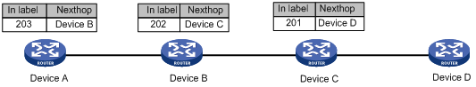
As shown in Figure 2, the devices are running the same IGP. After IGP adjacencies are established between the devices, Device A, Device B, and Device C allocates labels and creates label forwarding entries as follows:
· Device A allocates label 203 to the link to its neighbor Device B.
· Device B allocates label 202 to the link to its neighbor Device C.
· Device C allocates label 201 to the link to its neighbor Device D.
· Device A creates a label forwarding entry with incoming label 203 and next hop Device B.
· Device B creates a label forwarding entry with incoming label 202 and next hop Device C.
· Device C creates a label forwarding entry with incoming label 201 and next hop Device D.
SRLSP setup
You can use the following methods to create SRLSPs:
· Manually configure an SRLSP.
To configure an SRLSP, you must specify the label stack for packets to be forwarded along the SRLSP on the ingress node. Each label in the stack corresponds to a prefix SID or adjacency SID. The system can look for the outgoing label and next hop based on the prefix SID or adjacency SID.
· Configure SR nodes to use BGP or an IGP to dynamically establish an SRLSP.
SR nodes follow these steps to establish SRLSPs:
a. Use BGP or an IGP to collect prefix SID information from the MPLS SR network.
b. Calculate the shortest paths to other SR nodes based on the collected prefix SID information and the BGP or IGP network topology.
c. Establish SRLSPs based on the shortest paths.
· Configure a controller to deploy SRLSP configuration to the device so the device creates SRLSPs.
For more information about controller configuration, see the user guide for the controller.
Packet forwarding in MPLS SR
Based on the SID allocation method, MPLS SR uses one of the following packet forwarding methods:
· Prefix SID-based packet forwarding—The ingress node encapsulates the prefix SID for the egress node to a packet. The transit nodes forward the packet based on label forwarding entries.
· Adjacency SID-based packet forwarding—The ingress node encapsulates the label stack that contains the adjacency SIDs of all links along the forwarding path to a packet. Each transit node uses the top label in the label stack to determine the next hop and pops the top label before forwarding the packet to the next hop.
· Prefix and adjacency SID-based packet forwarding—The nodes use prefix SID-based packet forwarding in combination with adjacency-based packet forwarding.
Prefix SID-based packet forwarding within the same AS
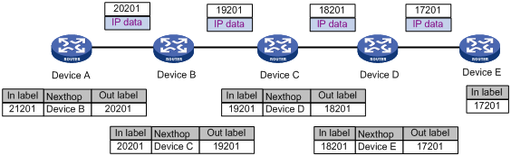
Figure 3 shows how a packet is forwarded along the SRLSP from Device A to Device E based on prefix SIDs. In this example, the outgoing label for the packet is 21201 on Device A.
1. Ingress node Device A searches for a forwarding entry for label 21201, adds outgoing label 20201 to the packet and sends the packet to the next hop (Device B).
2. When transit node Device B receives the packet, it searches for a label forwarding entry that matches the label in the packet. Then, Device B uses the outgoing label of the matched entry (19201) to replace the label in the packet and forwards the packet to the next hop (Device C).
3. Transit nodes Device C and Device D process the packet in the same way Device B does.
4. When egress node Device E receives the packet, it removes the label and forwards the packet by IP address.
Figure 3 Prefix SID-based packet forwarding within the same AS
Adjacency SID-based packet forwarding
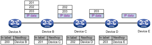
Figure 4 shows how a packet is forwarded along the SRLSP from Device A to Device E based on adjacency SIDs. In this example, the label stack for the packet is configured as (200, 201, 202, and 203) on Device A.
1. Ingress node Device A searches for a forwarding entry for the top label (200) to determine the next hop. Then, Device A adds label stack (201, 202, and 203) to the packet, and forwards the packet to the next hop (Device B).
2. When transit node Device B receives the packet, it searches for a forwarding entry for the top label (201) to determine the next hop. Then, Device B removes the top label from the stack and forwards the packet to the next hop (Device C).
3. When transit node Device C receives the packet, it searches for a forwarding entry for the top label (202) to determine the next hop. Then, Device C removes the top label from the stack and forwards the packet to the next hop (Device D).
4. When transit node Device D receives the packet, it searches for a forwarding entry for the label (203) to determine the next hop. Then, Device D removes the label stack from the packet and forwards the packet to the next hop (Device E).
5. When egress node Device E receives the packet, it forwards the packet by IP address.
Figure 4 Adjacency SID-based packet forwarding
Prefix and adjacency SID-based packet forwarding
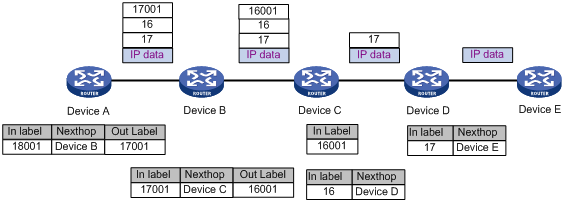
Figure 5 shows how a packet is forwarded along the SRLSP from Device A to Device E based on prefix SIDs and adjacency SIDs. In this example, the index value for the prefix SID of Device C is 1. The prefix SIDs for Device A, Device B, and Device C are 18001, 17001, and 16001, respectively. The Adjacency SIDs that Device C and Device D allocate for the adjacent links are 16 and 17, respectively. On Device A, the label stack for the packet is (18001, 16, 17).
1. Ingress node Device A searches for a forwarding entry for label 18001 to determine the outgoing label (17001) and next hop (Device B). Device A swaps label 18001 with 17001. Then, it adds label stack (17001, 16, 17) to the packet and sends the packet to the next hop (Device B).
2. When transit node Device B receives the packet, it searches for a label forwarding entry that matches the top label in the label stack (17001). Then, Device B uses the outgoing label of the matched entry (16001) to replace the top label and forwards the packet to the next hop (Device C).
3. When transit node Device C receives the packet, it removes the top label 16001 and searches for a forwarding entry for the next label (16) to determine the next hop. Then, Device C removes label 16 from the stack and forwards the packet to the next hop (Device D).
4. When transit node Device D receives the packet, it searches for a forwarding entry for the label (17) to determine the next hop. Then, Device D removes the label stack from the packet and forwards the packet to the next hop (Device E).
5. When egress node Device E receives the packet, it forwards the packet by IP address.
Figure 5 Prefix and adjacency SID-based packet forwarding
MPLS SR and LDP interworking
MPLS SR and LDP interworking enables MPLS SR networks and MPLS LDP networks to communicate and cooperate for MPLS forwarding.
MPLS SR and LDP interworking supports the SR over LDP mode. This mode enables MPLS SR networks to communicate through an LDP network.
SR over LDP
For MPLS SR networks to communicate across an LDP network, the SR/LDP border devices must be able to connect the SR LSP and the LDP LSP as follows:
· MPLS SR to LDP interwoking—The border device installs SR-to-LDP label forwarding entries. For a packet from the MPLS SR network to the LDP network, the MPLS SR label forwarding entry on the border device does not have an outgoing label. The border device uses the outgoing label of the LDP label forwarding entry for the same destination address as the outgoing label of the packet.
· LDP to MPLS SR interwoking—The border device installs LDP-to-SR label forwarding entries. For a packet from the LDP network to the MPLS SR network, the LDP forwarding entry on the border device does not have an outgoing label. The border device must use the outgoing label of the MPLS SR forwarding entry for the same destination address as the outgoing label of the packet.
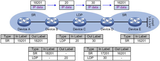
As shown in Figure 6, Device A, Device B, Device D, and Device E are running MPLS SR. After you assign index value 201 to loopback interface address 3.3.3.3/32 on Device E, Device E will advertise the index value and the local SRGB. After Device A, Device B, and Device D receive the message, they will install their respective MPLS SR label forwarding entries. Device B, Device C, and Device D are running LDP. They allocate labels to destination address 3.3.3.3/32 to generate the LDP label forwarding entries.
A packet that Device A sends to Device E will be forwarded as follows:
1. Ingress node Device A encapsulates label 18201 to the packet and forwards the packet to transit node Device B.
2. Transit node Device B searches for an MPLS SR label forwarding entry for incoming label 18201 and finds that the entry does not have an outgoing label. Because an LDP label forwarding entry with outgoing label 20 exists for the destination address (3.3.3.3/32), Device B encapsulates outgoing label 20 in the packet. Then Device B sends the packet to transit node Device C.
3. Device C forwards the packet to Device D based on its LDP label forwarding entries. The outgoing label is 30.
4. Device D searches for an LDP label forwarding entry for incoming label 30 and finds that the entry does not have an outgoing label. Because an MPLS SR label forwarding entry with outgoing label 16201 exists for the destination address (3.3.3.3/32), Device B encapsulates outgoing label 16201 in the packet. Then Device D sends the packet to egress node Device E.
5. Egress node Device E deletes the incoming label and forwards the packet by IP address.
MPLS SR tasks at a glance
IP traffic forwarding over SRLSPs tasks at a glance
To forward IP traffic over SRLSPs, perform the following configuration tasks:
1. Configuring segments
Select one of the following tasks:
? Configuring IGP-based SID advertisement
2. (Optional.) Configuring the device to prefer SRLSPs in traffic forwarding
3. (Optional.) Configuring MPLS SR and LDP interworking
MPLS TE traffic forwarding over static SRLSPs tasks at a glance
To forward MPLS TE traffic over static SRLSPs, perform the following configuration tasks:
1. Configuring segments
Select one of the following tasks:
? Configuring IGP-based SID advertisement
2. Configuring an MPLS TE tunnel over a static SRLSP
3. (Optional.) Configuring MPLS SR and LDP interworking
Configuring static segments
Prerequisites
Before you configure static segments for a static SRLSP, perform the following tasks:
· Determine the ingress node, transit nodes, and egress node of the static SRLSP.
· Determine the incoming label for the adjacency segment from a node to next hop of the node. Determine the incoming label of the prefix segment for the destination IP address on each node. On a device, a static SRLSP, a static LSP, and a static CRLSP cannot use the same incoming label. For more information about CRLSP, see MPLS TE configuration in MPLS Configuration Guide.
· Enable MPLS on all nodes and interfaces that will participate in MPLS forwarding. For information about enabling MPLS, see MPLS basics configuration in MPLS Configuration Guide.
Configuring a static adjacency segment
Restrictions and guidelines
This task is required on all nodes of a static SRLSP.
Multiple static SRLSPs can share an adjacency segment.
If you specify the next hop address for a static adjacency segment, make sure the following requirements are met:
· The device has a route to the next hop address.
· MPLS is enabled on the output interface of the route.
If you specify an output interface for a static adjacency segment, make sure the following requirements are met:
· The interface is up.
· The interface can receive direct routes.
· MPLS is enabled on the interface.
A static adjacency segment must use a different incoming label than existing static LSPs, static PWs, and static CRLSPs. If not, the configured adjacency segment is unavailable. The adjacency segment cannot become available even if you change the incoming label of the static LSP, static PW, or static CRLSP. To resolve this problem, you must delete the existing adjacency segment and configure a new one with a different incoming label.
Procedure
1. Enter system view.
system-view
2. Configure a static adjacency segment.
static-sr-mpls adjacency adjacency-path-name in-label label-value { nexthop ip-address | outgoing-interface interface-type interface-number }
The next hop address for a static adjacency segment cannot be a local public IP address.
Configuring a static prefix segment
Restrictions and guidelines
This task is required on all nodes of a static SRLSP.
Multiple static SRLSPs to the same destination can share a prefix segment.
A prefix segment must use the next hop or output interface of the optimal route to the destination address of the prefix segment. You can configure multiple prefix segments to the destination address for load sharing if the optimal route has more than one next hop or output interface. To avoid configuration failure, make sure all prefix segments use the same prefix segment name and incoming label.
If you specify only the prefix-path-name argument, the undo static-sr-mpls prefix command deletes all prefix segments with the specified name. If you specify all parameters, only the prefix segment that matches the specified name, destination IP address, and next hop or output interface is deleted.
Procedure
1. Enter system view.
system-view
2. Configure a static prefix segment.
static-sr-mpls prefix prefix-path-name destination ip-address { mask-length | mask } in-label in-label-value [ { nexthop ip-address | outgoing-interface interface-type interface-number } out-label out-label-value ]
The next hop address for a static prefix segment cannot be a local public IP address.
Configuring IGP-based SID advertisement
IGP-based SID advertisement tasks at a glance
Perform the following tasks on each node along an SRLSP:
1. Configuring the IGP to support MPLS SR
2. Perform one or more of the following tasks:
? Enabling MPLS SR adjacency label allocation for the IGP
Perform this task if you are configuring prefix SIDs.
Prerequisites for configuring IGP-based SID advertisement
Before you configure IGP-based SID advertisement, perform the following tasks:
· Determine the ingress node, transit nodes, and egress node of an SRLSP.
· Determine the following items for each node:
? Index value for the prefix SID.
? MPLS SRGB.
· Enable MPLS on all nodes and interfaces that will participate in MPLS forwarding. For information about enabling MPLS, see basic MPLS configuration in MPLS Configuration Guide.
Configuring the IGP to support MPLS SR
Prerequisites
For MPLS SR to take effect, perform the following tasks before configuring the IGP to support MPLS SR:
· If the IGP is IS-IS, set the cost style to wide, compatible, or wide-compatible. For more information about the cost style, see IS-IS configuration in Layer 3—IP Routing Configuration Guide.
· If the IGP is OSPF, enable opaque LSA reception and advertisement capability. For more information about the capability, see OSPF configuration in Layer 3—IP Routing Configuration Guide.
Configuring IS-IS to support MPLS SR
1. Enter system view.
system-view
2. Enter IS-IS view.
isis process-id
3. Enter IS-IS IPv4 unicast address family view.
address-family ipv4
4. Enable MPLS SR.
segment-routing mpls
By default, MPLS SR is disabled.
Configuring OSPF to support MPLS SR
1. Enter system view.
system-view
2. Enter OSPF view.
ospf process-id
3. Enable MPLS SR.
segment-routing mpls
By default, MPLS SR is disabled.
Configuring prefix SIDs
About prefix SID configuration
Configuring a prefix SID in lookback interface view binds the SID with the IP address of the loopback interface.
To configure a prefix SID, use one of the following methods:
· Specify an absolute value in the SRGB. The absolute value is used as the prefix SID.
· Specify an index value. The sum of the index value and the SRGB base value is used as the prefix SID. The prefix SID must be in the SRGB.
Restrictions and guidelines
To use a prefix SID for a group of SR nodes in anycast scenarios, specify the n-flag-clear keyword to set the Node-SID flag bit of the prefix SID to 0.
To configure an IS-IS prefix SID, you must enable an IS-IS process on the loopback interface.
A configured OSPF prefix SID takes effect only if the OSPF process enabled on the loopback interface is the same as the OSPF process associated with the prefix SID.
On a loopback interface that belongs to a VPN instance, the explicit-null keyword is not supported.
Configuring an IS-IS prefix SID
1. Enter system view.
system-view
2. Enter loopback interface view.
interface loopback interface-number
3. Configure an IS-IS prefix SID.
isis prefix-sid { absolute absolute-value | index index-value } [ n-flag-clear | { explicit-null | no-php } ] *
By default, no IS-IS prefix SID is configured.
Configuring an OSPF prefix SID
1. Enter system view.
system-view
2. Enter loopback interface view.
interface loopback interface-number
3. Configure an OSPF prefix SID.
ospf process-id prefix-sid { absolute absolute-value | index index-value } [ n-flag-clear ] [ explicit-null ]
By default, no OSPF prefix SID is configured.
Enabling MPLS SR adjacency label allocation for the IGP
Restrictions and guidelines
For this feature to take effect, you must enable MPLS SR.
Enabling MPLS SR adjacency label allocation for IS-IS
1. Enter system view.
system-view
2. Enter IS-IS view.
isis process-id
3. Enter IS-IS IPv4 unicast address family view.
address-family ipv4
4. Enable MPLS SR adjacency label allocation.
segment-routing adjacency enable
By default, MPLS SR adjacency label allocation is disabled.
Enabling MPLS SR adjacency label allocation for OSPF
1. Enter system view.
system-view
2. Enter OSPF view.
ospf process-id
3. Enable MPLS SR adjacency label allocation.
segment-routing adjacency enable
By default, MPLS SR adjacency label allocation is disabled.
Configuring the MPLS SRGB
Restrictions and guidelines
To configure the SRGB of a node successfully, make sure the SRGB contains the prefix SID configured for the node.
MPLS reserves labels in the range of 16000 to 24000 for SRGB. The minimum and maximum label values of the SRBG must be in the range.
Configuring the MPLS SRGB for IS-IS
1. Enter system view.
system-view
2. Enter IS-IS view.
isis process-id
3. Configure the MPLS SRGB.
segment-routing global-block minivalue maxivalue
By default, the minimum label value is 16000, and the maximum label value is 24000.
Configuring the MPLS SRGB for OSPF
1. Enter system view.
system-view
2. Enter OSPF view.
ospf process-id
3. Configure the MPLS SRGB.
segment-routing global-block minivalue maxivalue
By default, the minimum label value is 16000, and the maximum label value is 24000.
Configuring the device to prefer SRLSPs in traffic forwarding
About preferring SRLSPs in traffic forwarding
This feature enables the device to preferentially use SRLSPs to forward traffic when both SRLSPs and LDP LSPs are available for traffic forwarding. If you do not configure this feature, the device prefers to use LDP LSPs for traffic forwarding.
Restrictions and guidelines
This feature takes effect only when MPLS SR is enabled and SRLSPs use prefix SIDs.
Configuring the device to prefer SRLSPs established by IS-IS in traffic forwarding
1. Enter system view.
system-view
2. Enter IS-IS view.
isis process-id
3. Configure the device to prefer SRLSPs in traffic forwarding.
segment-routing sr-prefer [ prefix-list prefix-list-name ]
By default, the device prefers LDP LSPs to SRLSPs.
Configuring the device to prefer SRLSPs established by OSPF in traffic forwarding
1. Enter system view.
system-view
2. Enter OSPF view.
ospf process-id
3. Configure the device to prefer SRLSPs in traffic forwarding.
segment-routing sr-prefer [ prefix-list prefix-list-name ]
By default, the device prefers LDP LSPs to SRLSPs.
Configuring an MPLS TE tunnel over a static SRLSP
Tasks at a glance
1. Enable MPLS TE.
Perform this task on all nodes that the MPLS TE tunnel traverses. For more information, see MPLS TE configuration in MPLS Configuration Guide.
Perform this task on the ingress node of the MPLS TE tunnel.
3. Create the tunnel interface and specify the destination address of the tunnel.
Perform this task on the ingress node of the MPLS TE tunnel. For more information, see MPLS TE configuration in MPLS Configuration Guide.
4. Binding a static SRLSP to an MPLS TE tunnel interface
Perform this task on the ingress node of the MPLS TE tunnel.
5. Configure static routes or policy-based routing to direct traffic to the MPLS TE tunnel.
Perform this task on the ingress node of the MPLS TE tunnel. For more information, see MPLS TE configuration in MPLS Configuration Guide.
Configuring a static SRLSP
1. Enter system view.
system-view
2. Configure a static SRLSP.
static-sr-mpls lsp lsp-name out-label out-label-value&<1-14>
Binding a static SRLSP to an MPLS TE tunnel interface
1. Enter system view.
system-view
2. Enter MPLS TE tunnel interface view.
interface tunnel tunnel-number [ mode mpls-te ]
3. Set the MPLS TE tunnel establishment mode to static.
mpls te signaling static
By default, MPLS TE uses RSVP-TE to establish a tunnel.
For more information about this command, see MPLS Command Reference.
4. Bind a static SRLSP to the MPLS TE tunnel interface.
mpls te static-sr-mpls lsp-name [ backup ]
By default, an MPLS TE tunnel does not use a static SRLSP.
The specified SRLSP must be already created by using the static-sr-mpls lsp command.
You can specify the backup keyword to bind a backup static SRLSP only if both the main and backup SRLSPs are established by using the adjacency segment method.
Configuring MPLS SR and LDP interworking
Restrictions and guidelines for MPLS SR and LDP interworking
To configure MPLS SR and LDP interworking, make sure the SRLSP uses prefix SIDs.
In the current software version, the SRMS and SRMC devices support only IS-IS-based MPLS SR.
SR over LDP tasks at a glance
1. Configuring the IGP to support MPLS SR
Prerequisites for MPLS SR and LDP internetworking
Before you configure MPLS SR and LDP internetworking, perform the following tasks:
· Determine the ingress node, transit nodes, and egress node of an SRLSP.
· Determine the index value for the prefix SID of each node.
· Enable MPLS on all nodes and interfaces that will participate in MPLS forwarding. For information about enabling MPLS, see basic MPLS configuration in MPLS Configuration Guide.
Display and maintenance commands for MPLS SR
Execute display commands in any view.
|
Task |
Command |
|
Display IS-IS SR adjacency segment information. |
display isis segment-routing adjacency [ process-id ] |
|
Display IS-IS SRGB information. |
display isis segment-routing global-block [ level-1 | level-2 ] [ process-id ] |
|
Display static SRLSP and adjacency segment information. |
display mpls static-sr-lsp { lsp [ lsp-name ] | adjacency [ adjacency-path-name ] } |
|
Display static prefix segment information. |
display mpls static-sr-mpls prefix [ path lsp-name | destination ip-address [ mask | mask-length ] ] |
|
Display OSPF SRGB information. |
display ospf [ process-id ] [ area area-id ] segment-routing global-block |
MPLS SR configuration examples
Example: Configuring MPLS SR based on static segments
Network configuration
As shown in Figure 7, Router A, Router B, Router C, Router D, and Router E are running IS-IS.
Establish an MPLS TE tunnel over a static SRLSP from Router A to Router D to transmit data between the IP networks. The static SRLSP traverses three adjacency segments: Router A—Router B, Router B—Router C, and Router C—Router D.
Establish an MPLS TE tunnel over a static SRLSP from Router A to Router E to transmit data between the IP networks. The static SRLSP traverses three segments: Router A—Router B (adjacency segment), Router B—Router C (prefix segment), and Router C—Router E (adjacency segment).
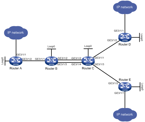
Table 1 Interface and IP address assignment
|
Device |
Interface |
IP address |
Device |
Interface |
IP address |
|
Router A |
Loop0 |
1.1.1.9/32 |
Router B |
Loop0 |
2.2.2.9/32 |
|
|
GE3/1/1 |
100.1.1.1/24 |
|
GE3/1/1 |
10.1.1.2/24 |
|
|
GE3/1/2 |
10.1.1.1/24 |
|
GE3/1/2 |
20.1.1.1/24 |
|
|
|
|
|
GE3/1/3 |
60.1.1.1/24 |
|
Router C |
Loop0 |
3.3.3.9/32 |
Router D |
Loop0 |
4.4.4.9/32 |
|
|
GE3/1/1 |
30.1.1.1/24 |
|
GE3/1/1 |
100.1.2.1/24 |
|
|
GE3/1/2 |
20.1.1.2/24 |
|
GE3/1/2 |
30.1.1.2/24 |
|
|
GE3/1/3 |
50.1.1.1/24 |
|
|
|
|
|
GE3/1/4 |
60.1.1.2/24 |
|
|
|
|
Router E |
Loop0 |
5.5.5.9/32 |
|
|
|
|
|
GE3/1/1 |
200.1.2.1/24 |
|
|
|
|
|
GE3/1/2 |
50.1.1.2/24 |
|
|
|
Procedure
1. Configure IP addresses and masks for interfaces. (Details not shown.)
2. Configure IS-IS to advertise interface addresses, including the loopback interface addresses. (Details not shown.)
3. Execute the display ip routing-table command on each router to verify that the routers have learned the routes to one another, including the routes to the loopback interfaces. (Details not shown.)
4. Configure LSR IDs, and enable MPLS and MPLS TE:
# Configure Router A.
<RouterA> system-view
[RouterA] mpls lsr-id 1.1.1.9
[RouterA] mpls te
[RouterA-te] quit
[RouterA] interface gigabitethernet 3/1/2
[RouterA-GigabitEthernet3/1/2] mpls enable
[RouterA-GigabitEthernet3/1/2] quit
# Configure Router B.
<RouterB> system-view
[RouterB] mpls lsr-id 2.2.2.9
[RouterB] mpls te
[RouterB-te] quit
[RouterB] interface gigabitethernet 3/1/1
[RouterB-GigabitEthernet3/1/1] mpls enable
[RouterB-GigabitEthernet3/1/1] quit
[RouterB] interface gigabitethernet 3/1/2
[RouterB-GigabitEthernet3/1/2] mpls enable
[RouterB-GigabitEthernet3/1/2] quit
[RouterB] interface gigabitethernet 3/1/3
[RouterB-GigabitEthernet3/1/3] mpls enable
[RouterB-GigabitEthernet3/1/3] quit
# Configure Router C.
<RouterC> system-view
[RouterC] mpls lsr-id 3.3.3.9
[RouterC] mpls te
[RouterC-te] quit
[RouterC] interface gigabitethernet 3/1/1
[RouterC-GigabitEthernet3/1/1] mpls enable
[RouterC-GigabitEthernet3/1/1] quit
[RouterC] interface gigabitethernet 3/1/2
[RouterC-GigabitEthernet3/1/2] mpls enable
[RouterC-GigabitEthernet3/1/2] quit
[RouterC] interface gigabitethernet 3/1/3
[RouterC-GigabitEthernet3/1/3] mpls enable
[RouterC-GigabitEthernet3/1/3] quit
[RouterC] interface gigabitethernet 3/1/4
[RouterC-GigabitEthernet3/1/4] mpls enable
[RouterC-GigabitEthernet3/1/4] quit
# Configure Router D.
<RouterD> system-view
[RouterD] mpls lsr-id 4.4.4.9
[RouterD] mpls te
[RouterD-te] quit
[RouterD] interface gigabitethernet 3/1/2
[RouterD-GigabitEthernet3/1/2] mpls enable
[RouterD-GigabitEthernet3/1/2] quit
# Configure Router E.
<RouterE> system-view
[RouterE] mpls lsr-id 5.5.5.9
[RouterE] mpls te
[RouterE-te] quit
[RouterE] interface gigabitethernet 3/1/2
[RouterE-GigabitEthernet3/1/2] mpls enable
[RouterE-GigabitEthernet3/1/2] quit
5. Configure adjacency and prefix segments on the nodes:
# On Router A, create adjacency segment adjacency-1, and bind incoming label 16 to next hop address 10.1.1.2.
[RouterA] static-sr-mpls adjacency adjacency-1 in-label 16 nexthop 10.1.1.2
# On Router B, create adjacency segment adjacency-2, and bind incoming label 21 to next hop address 20.1.1.2.
[RouterB] static-sr-mpls adjacency adjacency-2 in-label 21 nexthop 20.1.1.2
# On Router B, create prefix segments prefix-1 to destination IP address 5.5.5.9. Bind incoming label 16000 to next hop addresses 20.1.1.2 and 60.1.1.2, and specify outgoing label 16001. Load balancing will occur between Router B and Router C.
[RouterB] static-sr-mpls prefix prefix-1 destination 5.5.5.9 32 in-label 16000 nexthop 20.1.1.2 out-label 16001
[RouterB] static-sr-mpls prefix prefix-1 destination 5.5.5.9 32 in-label 16000 nexthop 60.1.1.2 out-label 16001
# On Router C, create adjacency segment adjacency-1, and bind incoming label 30 to next hop address 30.1.1.2. Create adjacency segment adjacency-2, and bind incoming label 31 to next hop address 50.1.1.2.
[RouterC] static-sr-mpls adjacency adjacency-1 in-label 30 nexthop 30.1.1.2
[RouterC] static-sr-mpls adjacency adjacency-2 in-label 31 nexthop 50.1.1.2
# On Router C, create prefix segment prefix-1 to destination IP address 5.5.5.9, and specify incoming label 16001.
[RouterC] static-sr-mpls prefix prefix-1 destination 5.5.5.9 32 in-label 16001
6. On Router A, establish static SRLSP static-sr-lsp-1 to Router D and static SRLSP static-sr-lsp-2 to Router E:
# Configure Router A as the ingress node of static SRLSP static-sr-lsp-1 and configure a label stack of [16, 21, 30].
[RouterA] static-sr-mpls lsp static-sr-lsp-1 out-label 16 21 30
# Configure Router A as the ingress node of static SRLSP static-sr-lsp-2 and configure a label stack of [16, 16000, 31].
[RouterA] static-sr-mpls lsp static-sr-lsp-2 out-label 16 16000 31
7. Configure MPLS TE tunnels over static SRLSPs on Router A:
# Establish static MPLS TE tunnel 1 to Router D and specify the LSR ID of Router D as the tunnel destination address. Bind static SRLSP static-sr-lsp-1 to MPLS TE tunnel interface 1.
[RouterA] interface tunnel 1 mode mpls-te
[RouterA-Tunnel1] ip address 6.1.1.1 255.255.255.0
[RouterA-Tunnel1] destination 4.4.4.9
[RouterA-Tunnel1] mpls te signaling static
[RouterA-Tunnel1] mpls te static-sr-mpls static-sr-lsp-1
[RouterA-Tunnel1] quit
# Establish static MPLS TE tunnel 2 to Router E and specify the LSR ID of Router E as the tunnel destination address. Bind static SRLSP static-sr-lsp-2 to MPLS TE tunnel interface 2.
[RouterA] interface tunnel 2 mode mpls-te
[RouterA-Tunnel2] ip address 7.1.1.1 255.255.255.0
[RouterA-Tunnel2] destination 5.5.5.9
[RouterA-Tunnel2] mpls te signaling static
[RouterA-Tunnel2] mpls te static-sr-mpls static-sr-lsp-2
[RouterA-Tunnel2] quit
8. On Router A, configure two static routes to direct traffic destined for 100.1.2.0/24 and 200.1.2.0/24 to MPLS TE tunnel 1 and tunnel 2, respectively.
[RouterA] ip route-static 100.1.2.0 24 tunnel 1 preference 1
[RouterA] ip route-static 200.1.2.0 24 tunnel 2 preference 1
Verifying the configuration
# Display the MPLS TE tunnel information on Router A.
[RouterA] display mpls te tunnel-interface
Tunnel Name : Tunnel 1
Tunnel State : Up (Main CRLSP up)
Tunnel Attributes :
LSP ID : 1 Tunnel ID : 0
Admin State : Normal
Ingress LSR ID : 1.1.1.9 Egress LSR ID : 4.4.4.9
Signaling : Static Static CRLSP Name : -
Static SRLSP Name : static-sr-lsp-1/-
Resv Style : -
Tunnel mode : -
Reverse-LSP name : -
Reverse-LSP LSR ID : - Reverse-LSP Tunnel ID: -
Class Type : - Tunnel Bandwidth : -
Reserved Bandwidth : -
Setup Priority : 0 Holding Priority : 0
Affinity Attr/Mask : -/-
Explicit Path : -
Backup Explicit Path : -
Metric Type : TE
Record Route : - Record Label : -
FRR Flag : - Backup Bandwidth Flag: -
Backup Bandwidth Flag: - Backup Bandwidth Type: -
Backup Bandwidth : -
Bypass Tunnel : - Auto Created : -
Route Pinning : -
Retry Limit : 3 Retry Interval : 2 sec
Reoptimization : - Reoptimization Freq : -
Backup Type : - Backup LSP ID : -
Auto Bandwidth : - Auto Bandwidth Freq : -
Min Bandwidth : - Max Bandwidth : -
Collected Bandwidth : -
Tunnel Name : Tunnel 2
Tunnel State : Up (Main CRLSP up)
Tunnel Attributes :
LSP ID : 1 Tunnel ID : 1
Admin State : Normal
Ingress LSR ID : 1.1.1.9 Egress LSR ID : 5.5.5.9
Signaling : Static Static CRLSP Name : -
Static SRLSP Name : static-sr-lsp-2/-
Resv Style : -
Tunnel mode : -
Reverse-LSP name : -
Reverse-LSP LSR ID : - Reverse-LSP Tunnel ID: -
Class Type : - Tunnel Bandwidth : -
Reserved Bandwidth : -
Setup Priority : 0 Holding Priority : 0
Affinity Attr/Mask : -/-
Explicit Path : -
Backup Explicit Path : -
Metric Type : TE
Record Route : - Record Label : -
FRR Flag : - Bandwidth Protection : -
Backup Bandwidth Flag: - Backup Bandwidth Type: -
Backup Bandwidth : -
Bypass Tunnel : - Auto Created : -
Route Pinning : -
Retry Limit : 3 Retry Interval : 2 sec
Reoptimization : - Reoptimization Freq : -
Backup Type : - Backup LSP ID : -
Auto Bandwidth : - Auto Bandwidth Freq : -
Min Bandwidth : - Max Bandwidth : -
Collected Bandwidth : -
# Display static SRLSP establishment on each router by using the display mpls lsp or display mpls static-sr-lsp command.
[RouterA] display mpls lsp
FEC Proto In/Out Label Out Inter/NHLFE/LSINDEX
1.1.1.9/0/46565 StaticCR -/21 GE3/1/2
30
1.1.1.9/1/46565 StaticCR -/16000 GE3/1/2
31
- StaticCR 16/- GE3/1/2
10.1.1.2 Local -/- GE3/1/2
Tunnel0 Local -/- NHLFE1
Tunnel1 Local -/- NHLFE2
[RouterB] display mpls lsp
FEC Proto In/Out Label Out Inter/NHLFE/LSINDEX
5.5.5.9/32 StaticCR 16000/16001 GE3/1/2
5.5.5.9/32 StaticCR 16000/16001 GE3/1/3
- StaticCR 21/- GE3/1/2
20.1.1.2 Local -/- GE3/1/2
60.1.1.2 Local -/- GE3/1/3
[RouterC] display mpls lsp
FEC Proto In/Out Label Out Inter/NHLFE/LSINDEX
5.5.5.9/32 StaticCR 16001/- -
- StaticCR 30/- GE3/1/1
- StaticCR 31/- GE3/1/3
30.1.1.2 Local -/- GE3/1/1
50.1.1.2 Local -/- GE3/1/3
Example: Configuring MPLS SR based on ISIS-advertised SIDs
Network configuration
As shown in Figure 8, Router A, Router B, Router C and Router D are running IS-IS.
Configure dynamic SID allocation on loopback interfaces of the routers. Then, establish an SRLSP from Router A to Router D based on the allocated SIDs and configure an MPLS TE tunnel over the SRLSP to transmit data.
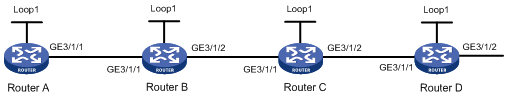
Table 2 Interface and IP address assignment
|
Device |
Interface |
IP address |
Device |
Interface |
IP address |
|
Router A |
Loop1 |
1.1.1.1/32 |
Router B |
Loop1 |
2.2.2.2/32 |
|
|
GE3/1/1 |
10.0.0.1/24 |
|
GE3/1/1 |
10.0.0.2/24 |
|
|
|
|
|
GE3/1/2 |
11.0.0.1/24 |
|
Router C |
Loop1 |
3.3.3.3/32 |
Router D |
Loop1 |
4.4.4.4/32 |
|
|
GE3/1/1 |
11.0.0.2/24 |
|
GE3/1/1 |
12.0.0.2/24 |
|
|
GE3/1/2 |
12.0.0.1/24 |
|
GE3/1/2 |
100.1.2.1/24 |
Procedure
1. Configure IP addresses and masks for interfaces. (Details not shown.)
2. Configure IS-IS on the routers and set the IS-IS cost style to wide:
# Configure Router A.
<RouterA> system-view
[RouterA] isis 1
[RouterA-isis-1] network-entity 00.0000.0000.0001.00
[RouterA-isis-1] cost-style wide
[RouterA-isis-1] quit
[RouterA] interface gigabitethernet 3/1/1
[RouterA-GigabitEthernet3/1/1] isis enable 1
[RouterA-GigabitEthernet3/1/1] quit
[RouterA] interface loopback 1
[RouterA-LoopBack1] isis enable 1
[RouterA-LoopBack1] quit
# Configure Router B.
<RouterB> system-view
[RouterB] isis 1
[RouterB-isis-1] network-entity 00.0000.0000.0002.00
[RouterB-isis-1] cost-style wide
[RouterB-isis-1] quit
[RouterB] interface gigabitethernet 3/1/1
[RouterB-GigabitEthernet3/1/1] isis enable 1
[RouterB-GigabitEthernet3/1/1] quit
[RouterB] interface gigabitethernet 3/1/2
[RouterB-GigabitEthernet3/1/2] isis enable 1
[RouterB-GigabitEthernet3/1/2] quit
[RouterB] interface loopback 1
[RouterB-LoopBack1] isis enable 1
[RouterB-LoopBack1] quit
# Configure Router C.
<RouterC> system-view
[RouterC] isis 1
[RouterC-isis-1] network-entity 00.0000.0000.0003.00
[RouterC-isis-1] cost-style wide
[RouterC-isis-1] quit
[RouterC] interface gigabitethernet 3/1/1
[RouterC-GigabitEthernet3/1/1] isis enable 1
[RouterC-GigabitEthernet3/1/1] quit
[RouterC] interface gigabitethernet 3/1/2
[RouterC-GigabitEthernet3/1/2] isis enable 1
[RouterC-GigabitEthernet3/1/2] quit
[RouterC] interface loopback 1
[RouterC-LoopBack1] isis enable 1
[RouterC-LoopBack1] quit
# Configure Router D.
<RouterD> system-view
[RouterD] isis 1
[RouterD-isis-1] network-entity 00.0000.0000.0004.00
[RouterD-isis-1] cost-style wide
[RouterD-isis-1] quit
[RouterD] interface gigabitethernet 3/1/1
[RouterD-GigabitEthernet3/1/1] isis enable 1
[RouterD-GigabitEthernet3/1/1] quit
[RouterD] interface gigabitethernet 3/1/2
[RouterD-GigabitEthernet3/1/2] isis enable 1
[RouterD-GigabitEthernet3/1/2] quit
[RouterD] interface loopback 1
[RouterD-LoopBack1] isis enable 1
[RouterD-LoopBack1] quit
3. Configure LSR IDs, and enable MPLS and MPLS TE on the routers:
# Configure Router A.
[RouterA] mpls lsr-id 1.1.1.1
[RouterA] mpls te
[RouterA-te] quit
[RouterA] interface gigabitethernet 3/1/1
[RouterA-GigabitEthernet3/1/1] mpls enable
[RouterA-GigabitEthernet3/1/1] quit
# Configure Router B.
[RouterB] mpls lsr-id 2.2.2.2
[RouterB] mpls te
[RouterB-te] quit
[RouterB] interface gigabitethernet 3/1/1
[RouterB-GigabitEthernet3/1/1] mpls enable
[RouterB-GigabitEthernet3/1/1] quit
[RouterB] interface gigabitethernet 3/1/2
[RouterB-GigabitEthernet3/1/2] mpls enable
[RouterB-GigabitEthernet3/1/2] quit
# Configure Router C.
[RouterC] mpls lsr-id 3.3.3.3
[RouterC] mpls te
[RouterC-te] quit
[RouterC] interface gigabitethernet 3/1/1
[RouterC-GigabitEthernet3/1/1] mpls enable
[RouterC-GigabitEthernet3/1/1] quit
[RouterC] interface gigabitethernet 3/1/2
[RouterC-GigabitEthernet3/1/2] mpls enable
[RouterC-GigabitEthernet3/1/2] quit
# Configure Router D.
[RouterD] mpls lsr-id 4.4.4.4
[RouterD] mpls te
[RouterD-te] quit
[RouterD] interface gigabitethernet 3/1/1
[RouterD-GigabitEthernet3/1/1] mpls enable
[RouterD-GigabitEthernet3/1/1] quit
4. Configure SRGBs and enable MPLS SR on the routers:
# Configure Router A.
[RouterA] isis 1
[RouterA-isis-1] segment-routing global-block 16000 16999
[RouterA-isis-1] address-family ipv4
[RouterA-isis-1-ipv4] segment-routing mpls
[RouterA-isis-1-ipv4] quit
[RouterA-isis-1] quit
# Configure Router B.
[RouterB] isis 1
[RouterB-isis-1] segment-routing global-block 17000 17999
[RouterB-isis-1] address-family ipv4
[RouterB-isis-1-ipv4] segment-routing mpls
[RouterB-isis-1-ipv4] quit
[RouterB-isis-1] quit
# Configure Router C.
[RouterC] isis 1
[RouterC-isis-1] segment-routing global-block 18000 18999
[RouterC-isis-1] address-family ipv4
[RouterC-isis-1-ipv4] segment-routing mpls
[RouterC-isis-1-ipv4] quit
[RouterC-isis-1] quit
# Configure Router D.
[RouterD] isis 1
[RouterD-isis-1] segment-routing global-block 19000 19999
[RouterD-isis-1] address-family ipv4
[RouterD-isis-1-ipv4] segment-routing mpls
[RouterD-isis-1-ipv4] quit
[RouterD-isis-1] quit
5. Configure IS-IS prefix SIDs for the routers:
# Configure Router A.
[RouterA] interface loopback 1
[RouterA-LoopBack1] isis prefix-sid index 10
# Configure Router B.
[RouterB] interface loopback 1
[RouterB-LoopBack1] isis prefix-sid index 20
# Configure Router C.
[RouterC] interface loopback 1
[RouterC-LoopBack1] isis prefix-sid index 30
# Configure Router D.
[RouterD] interface loopback 1
[RouterD-LoopBack1] isis prefix-sid index 40
6. On Router A, establish static SRLSP static-sr-lsp-1 to Router D and configure an MPLS TE tunnel over the static SRLSP:
# Configure Router A as the ingress node of static SRLSP static-sr-lsp-1 and specify the prefix label that Router A allocated to Router D (16040) as the outgoing label.
[RouterA] static-sr-mpls lsp static-sr-lsp-1 out-label 16040
# Establish static MPLS TE tunnel 1 to Router D and specify the LSR ID of Router D as the tunnel destination address. Bind static SRLSP static-sr-lsp-1 to MPLS TE tunnel interface 1.
[RouterA] interface tunnel 1 mode mpls-te
[RouterA-Tunnel1] ip address 6.1.1.1 255.255.255.0
[RouterA-Tunnel1] destination 4.4.4.4
[RouterA-Tunnel1] mpls te signaling static
[RouterA-Tunnel1] mpls te static-sr-mpls static-sr-lsp-1
[RouterA-Tunnel1] quit
7. On Router A, configure a static route to direct traffic destined for 100.1.2.0/24 to MPLS TE tunnel 1.
[RouterA] ip route-static 100.1.2.0 24 tunnel 1 preference 1
Verifying the configuration
# Display IS-IS process information on Router A.
[RouterA] display isis
IS-IS(1) Protocol Information
Network entity : 00.0000.0000.0001.00
IS level : level-1
Cost style : Wide
Fast reroute : Disabled
Preference : 15
LSP length receive : 1497
LSP length originate
level-1 : 1497
Maximum imported routes : 100000
Timers
LSP-max-age : 1200
LSP-refresh : 900
SPF mode : Normal
SPF intervals : 5 50 200
Segment routing
MPLS : Enabled
Adjacency : Disabled
global block : 16000 16999
# Display detailed IS-IS interface information on Router A to view SID information for the loopback interface.
[RouterA] display isis interface verbose
Interface information for IS-IS(1)
----------------------------------
Interface: LoopBack1
Index IPv4 state IPv6 state Circuit ID MTU Type DIS
00002 Up Down 1 1536 L1/L2 --
SNPA address : 0000-0000-0000
IP address : 1.1.1.1
Secondary IP address(es) :
IPv6 link-local address :
Extended circuit ID : 2
CSNP timer value : L1 10 L2 10
Hello timer value : 10
Hello multiplier value : 3
LSP timer value : L12 33
LSP transmit-throttle count : L12 5
Cost : L1 0 L2 0
IPv6 cost : L1 0 L2 0
Priority : L1 64 L2 64
Retransmit timer value : L12 5
MPLS TE status : L1 Disabled L2 Disabled
IPv4 BFD : Disabled
IPv6 BFD : Disabled
IPv4 FRR LFA backup : Enabled
IPv6 FRR LFA backup : Enabled
IPv4 prefix suppression : Disabled
IPv6 prefix suppression : Disabled
IPv4 tag : 0
IPv6 tag : 0
Prefix-SID type : Index
Value : 10
Prefix-SID validity : Valid
# Display SRGB information on Router A.
[RouterA] display isis segment-routing global-block
Segment routing global block information for IS-IS(1)
-----------------------------------------------------
Level-1 SRGB
------------
System ID Base Range
-------------------------------------------------------------------------------
0000.0000.0001 16000 1000
0000.0000.0002 17000 1000
0000.0000.0003 18000 1000
0000.0000.0004 19000 1000
# Display detailed IS-IS routing information on Router A to view information about routes bound with labels.
[RouterA] display isis route verbose
Route information for IS-IS(1)
------------------------------
Level-1 IPv4 Forwarding Table
-----------------------------
IPv4 Dest : 10.0.0.0/24 Int. Cost : 10 Ext. Cost : NULL
Admin Tag : - Src Count : 2 Flag : D/L/-
InLabel : 4294967295 InLabel Flag: -/-/-/-/-/-
NextHop : Interface : ExitIndex :
Direct GE3/1/1 0x00000102
Nib ID : 0x0 OutLabel : 4294967295 OutLabelFlag: -
IPv4 Dest : 11.0.0.0/24 Int. Cost : 20 Ext. Cost : NULL
Admin Tag : - Src Count : 2 Flag : R/-/-
InLabel : 4294967295 InLabel Flag: -/-/-/-/-/-
NextHop : Interface : ExitIndex :
10.0.0.2 GE3/1/1 0x00000102
Nib ID : 0x14000004 OutLabel : 4294967295 OutLabelFlag: -
IPv4 Dest : 12.0.0.0/24 Int. Cost : 30 Ext. Cost : NULL
Admin Tag : - Src Count : 2 Flag : R/-/-
InLabel : 4294967295 InLabel Flag: -/-/-/-/-/-
NextHop : Interface : ExitIndex :
10.0.0.2 GE3/1/1 0x00000102
Nib ID : 0x14000004 OutLabel : 4294967295 OutLabelFlag: -
IPv4 Dest : 1.1.1.1/32 Int. Cost : 0 Ext. Cost : NULL
Admin Tag : - Src Count : 1 Flag : D/L/-
InLabel : 16010 InLabel Flag: -/N/-/-/-/-
NextHop : Interface : ExitIndex :
Direct Loop1 0x00000584
Nib ID : 0x0 OutLabel : 4294967295 OutLabelFlag: -
IPv4 Dest : 2.2.2.2/32 Int. Cost : 10 Ext. Cost : NULL
Admin Tag : - Src Count : 1 Flag : R/-/-
InLabel : 16020 InLabel Flag: -/N/-/-/-/-
NextHop : Interface : ExitIndex :
10.0.0.2 GE3/1/1 0x00000102
Nib ID : 0x14000003 OutLabel : 17020 OutLabelFlag: I
IPv4 Dest : 3.3.3.3/32 Int. Cost : 20 Ext. Cost : NULL
Admin Tag : - Src Count : 1 Flag : R/-/-
InLabel : 16030 InLabel Flag: -/N/-/-/-/-
NextHop : Interface : ExitIndex :
10.0.0.2 GE3/1/1 0x00000102
Nib ID : 0x14000002 OutLabel : 17030 OutLabelFlag: -
IPv4 Dest : 4.4.4.4/32 Int. Cost : 20 Ext. Cost : NULL
Admin Tag : - Src Count : 1 Flag : R/-/-
InLabel : 16040 InLabel Flag: -/N/-/-/-/-
NextHop : Interface : ExitIndex :
10.0.0.2 GE3/1/1 0x00000102
Nib ID : 0x14000002 OutLabel : 17040 OutLabelFlag: -
Flags: D-Direct, R-Added to Rib, L-Advertised in LSPs, U-Up/Down Bit Set
InLabel flags: R-Readvertisement, N-Node SID, P-no PHP
E-Explicit null, V-Value, L-Local
OutLabelFlags: E-Explicit null, I-Implicit null, N-Normal
# Display MPLS LSP information on Router A.
[RouterA] display mpls lsp
FEC Proto In/Out Label Out Inter/NHLFE/LSINDEX
10.0.0.2 Local -/- GE3/1/1
1.1.1.1/32 ISIS 16010/- -
2.2.2.2/32 ISIS 16020/3 GE3/1/1
2.2.2.2/32 ISIS -/3 GE3/1/1
3.3.3.3/32 ISIS 16030/17030 GE3/1/1
3.3.3.3/32 ISIS -/17030 GE3/1/1
4.4.4.4/32 ISIS 16040/17040 GE3/1/1
4.4.4.4/32 ISIS -/17040 GE3/1/1
Example: Configuring MPLS SR based on OSPF-advertised SIDs
Network configuration
As shown in Figure 9, Router A, Router B, Router C and Router D are running OSPF.
Configure dynamic SID allocation on loopback interfaces of the routers. Then, establish an SRLSP from Router A to Router D based on the allocated SIDs and configure an MPLS TE tunnel over the SRLSP to transmit data.
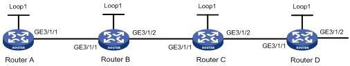
Table 3 Interface and IP address assignment
|
Device |
Interface |
IP address |
Device |
Interface |
IP address |
|
Router A |
Loop1 |
1.1.1.1/32 |
Router B |
Loop1 |
2.2.2.2/32 |
|
|
GE3/1/1 |
10.0.0.1/24 |
|
GE3/1/1 |
10.0.0.2/24 |
|
|
|
|
|
GE3/1/2 |
11.0.0.1/24 |
|
Router C |
Loop1 |
3.3.3.3/32 |
Router D |
Loop1 |
4.4.4.4/32 |
|
|
GE3/1/1 |
11.0.0.2/24 |
|
GE3/1/1 |
12.0.0.2/24 |
|
|
GE3/1/2 |
12.0.0.1/24 |
|
GE3/1/2 |
100.1.2.1/24 |
Procedure
1. Configure IP addresses and masks for interfaces. (Details not shown.)
2. Configure OSPF on the routers to achieve network level connectivity:
# Configure Router A.
<RouterA> system-view
[RouterA] ospf 1 router-id 1.1.1.1
[RouterA-ospf-1] quit
[RouterA] interface gigabitethernet 3/1/1
[RouterA-GigabitEthernet3/1/1] ospf 1 area 0
[RouterA-GigabitEthernet3/1/1] quit
[RouterA] interface loopback 1
[RouterA-LoopBack1] ospf 1 area 0
[RouterA-LoopBack1] quit
# Configure Router B.
<RouterB> system-view
[RouterB] ospf 1 router-id 2.2.2.2
[RouterB-ospf-1] quit
[RouterB] interface gigabitethernet 3/1/1
[RouterB-GigabitEthernet3/1/1] ospf 1 area 0
[RouterB-GigabitEthernet3/1/1] quit
[RouterB] interface gigabitethernet 3/1/2
[RouterB-GigabitEthernet3/1/2] ospf 1 area 0
[RouterB-GigabitEthernet3/1/2] quit
[RouterB] interface loopback 1
[RouterB-LoopBack1] ospf 1 area 0
[RouterB-LoopBack1] quit
# Configure Router C.
<RouterC> system-view
[RouterC] ospf 1 router-id 3.3.3.3
[RouterC-ospf-1] quit
[RouterC] interface gigabitethernet 3/1/1
[RouterC-GigabitEthernet3/1/1] ospf 1 area 0
[RouterC-GigabitEthernet3/1/1] quit
[RouterC] interface gigabitethernet 3/1/2
[RouterC-GigabitEthernet3/1/2] ospf 1 area 0
[RouterC-GigabitEthernet3/1/2] quit
[RouterC] interface loopback 1
[RouterC-LoopBack1] ospf 1 area 0
[RouterC-LoopBack1] quit
# Configure Router D.
<RouterD> system-view
[RouterD] ospf 1 router-id 4.4.4.4
[RouterD-ospf-1] quit
[RouterD] interface gigabitethernet 3/1/1
[RouterD-GigabitEthernet3/1/1] ospf 1 area 0
[RouterD-GigabitEthernet3/1/1] quit
[RouterD] interface gigabitethernet 3/1/2
[RouterD-GigabitEthernet3/1/2] ospf 1 area 0
[RouterD-GigabitEthernet3/1/2] quit
[RouterD] interface loopback 1
[RouterD-LoopBack1] ospf 1 area 0
[RouterD-LoopBack1] quit
3. Configure LSR IDs, and enable MPLS and MPLS TE:
# Configure Router A.
[RouterA] mpls lsr-id 1.1.1.1
[RouterA] mpls te
[RouterA-te] quit
[RouterA] interface gigabitethernet 3/1/1
[RouterA-GigabitEthernet3/1/1] mpls enable
[RouterA-GigabitEthernet3/1/1] quit
# Configure Router B.
[RouterB] mpls lsr-id 2.2.2.2
[RouterB] mpls te
[RouterB-te] quit
[RouterB] interface gigabitethernet 3/1/1
[RouterB-GigabitEthernet3/1/1] mpls enable
[RouterB-GigabitEthernet3/1/1] quit
[RouterB] interface gigabitethernet 3/1/2
[RouterB-GigabitEthernet3/1/2] mpls enable
[RouterB-GigabitEthernet3/1/2] quit
# Configure Router C.
[RouterC] mpls lsr-id 3.3.3.3
[RouterC] mpls te
[RouterC-te] quit
[RouterC] interface gigabitethernet 3/1/1
[RouterC-GigabitEthernet3/1/1] mpls enable
[RouterC-GigabitEthernet3/1/1] quit
[RouterC] interface gigabitethernet 3/1/2
[RouterC-GigabitEthernet3/1/2] mpls enable
[RouterC-GigabitEthernet3/1/2] quit
# Configure Router D.
[RouterD] mpls lsr-id 4.4.4.4
[RouterD] mpls te
[RouterD-te] quit
[RouterD] interface gigabitethernet 3/1/1
[RouterD-GigabitEthernet3/1/1] mpls enable
[RouterD-GigabitEthernet3/1/1] quit
4. Configure SRGBs and enable MPLS SR on the routers:
# Configure Router A.
[RouterA] ospf 1
[RouterA-ospf-1] segment-routing global-block 16000 16999
[RouterA-ospf-1] segment-routing mpls
[RouterA-ospf-1] quit
# Configure Router B.
[RouterB] ospf 1
[RouterB-ospf-1] segment-routing global-block 17000 17999
[RouterB-ospf-1] segment-routing mpls
[RouterB-ospf-1] quit
# Configure Router C.
[RouterC] ospf 1
[RouterC-ospf-1] segment-routing global-block 18000 18999
[RouterC-ospf-1] segment-routing mpls
[RouterC-ospf-1] quit
# Configure Router D.
[RouterD] ospf 1
[RouterD-ospf-1] segment-routing global-block 19000 19999
[RouterD-ospf-1] segment-routing mpls
[RouterD-ospf-1] quit
5. Configure OSPF prefix SIDs by specifying relative values on the routers:
# Configure Router A.
[RouterA] interface loopback 1
[RouterA-LoopBack1] ospf 1 prefix-sid index 10
[RouterA-LoopBack1] quit
# Configure Router B.
[RouterB] interface loopback 1
[RouterB-LoopBack1] ospf 1 prefix-sid index 20
# Configure Router C.
[RouterC] interface loopback 1
[RouterC-LoopBack1] ospf 1 prefix-sid index 30
# Configure Router D.
[RouterD] interface loopback 1
[RouterD-LoopBack1] ospf 1 prefix-sid index 40
6. On Router A, establish static SRLSP static-sr-lsp-1 to Router D and configure an MPLS TE tunnel over the static SRLSP:
# Configure Router A as the ingress node of static SRLSP static-sr-lsp-1 and specify the prefix label that Router A allocated to Router D (16040) as the outgoing label.
[RouterA] static-sr-mpls lsp static-sr-lsp-1 out-label 16040
# Establish static MPLS TE tunnel 1 to Router D and specify the LSR ID of Router D as the tunnel destination address. Bind static SRLSP static-sr-lsp-1 to MPLS TE tunnel interface 1.
[RouterA] interface tunnel 1 mode mpls-te
[RouterA-Tunnel1] ip address 6.1.1.1 255.255.255.0
[RouterA-Tunnel1] destination 4.4.4.4
[RouterA-Tunnel1] mpls te signaling static
[RouterA-Tunnel1] mpls te static-sr-mpls static-sr-lsp-1
[RouterA-Tunnel1] quit
7. On Router A, configure a static route to direct traffic destined for 100.1.2.0/24 to MPLS TE tunnel 1.
[RouterA] ip route-static 100.1.2.0 24 tunnel 1 preference 1
Verifying the configuration
# Display OSPF process information on Router A to view SID information for the loopback interface.
[RouterA] display ospf
OSPF Process 1 with Router ID 1.1.1.1
OSPF Protocol Information
RouterID: 1.1.1.1 Router type:
Route tag: 0
Multi-VPN-Instance is not enabled
Ext-community type: Domain ID 0x5, Route Type 0x306, Router ID 0x107
Domain ID: 0.0.0.0
Opaque capable
ISPF is enabled
SPF-schedule-interval: 5 50 200
LSA generation interval: 5 50 200
LSA arrival interval: 1000 500 500
Transmit pacing: Interval: 20 Count: 3
Default ASE parameters: Metric: 1 Tag: 1 Type: 2
Route preference: 10
ASE route preference: 150
SPF calculation count: 16
RFC 1583 compatible
Graceful restart interval: 120
SNMP trap rate limit interval: 10 Count: 7
Area count: 1 NSSA area count: 0
ExChange/Loading neighbors: 0
MPLS segment routing: Enabled
Segment routing adjacency : Disabled
Segment routing global block: 16000 16999
Area: 0.0.0.0 (MPLS TE not enabled)
Authentication type: None Area flag: Normal
SPF scheduled count: 4
ExChange/Loading neighbors: 0
Interface: 10.0.0.1 (GigabitEthernet3/1/1)
Cost: 1 State: DR Type: Broadcast MTU: 1500
Priority: 1
Designated router: 10.0.0.1
Backup designated router: 10.0.0.2
Timers: Hello 10, Dead 40, Poll 40, Retransmit 5, Transmit Delay 1
FRR backup: Enabled
Enabled by interface configuration (including secondary IP addresses)
Interface: 1.1.1.1 (LoopBack1)
Cost: 0 State: Loopback Type: PTP MTU: 1536
Timers: Hello 10, Dead 40, Poll 40, Retransmit 5, Transmit Delay 1
FRR backup: Enabled
Enabled by interface configuration (including secondary IP addresses)
Prefix-SID type: Index
Value: 20
Process ID: ospf 1
Prefix-SID validity: Valid
# Display SRGB information on Router A.
[RouterA] display ospf segment-routing global-block
OSPF Process 1 with Router ID 1.1.1.1
Segment Routing Global Block
Area: 0.0.0.0
Router ID Min SID Max SID Total
4.4.4.4 19000 19999 1000
3.3.3.3 18000 18999 1000
2.2.2.2 17000 17999 1000
1.1.1.1 16000 16999 1000
# Display detailed OSPF routing information on Router A to view information about routes bound with labels.
[RouterA] display ospf routing verbose
OSPF Process 1 with Router ID 1.1.1.1
Routing Table
Topology base (MTID 0)
Routing for network
Destination: 11.0.0.0/24
Priority: Low Type: Transit
AdvRouter: 3.3.3.3 Area: 0.0.0.0
SubProtoID: 0x1 Preference: 10
NextHop: 10.0.0.2 BkNextHop: N/A
IfType: Broadcast BkIfType: N/A
Interface: GE3/1/1 BkInterface: N/A
NibID: 0x13000005 Status: Normal
Cost: 2
InLabel: 4294967295
OutLabel: 4294967295 OutLabel flag: N
Destination: 10.0.0.0/24
Priority: Low Type: Transit
AdvRouter: 1.1.1.1 Area: 0.0.0.0
SubProtoID: 0x1 Preference: 10
NextHop: 0.0.0.0 BkNextHop: N/A
IfType: Broadcast BkIfType: N/A
Interface: GE3/1/1 BkInterface: N/A
NibID: 0x13000001 Status: Direct
Cost: 1
InLabel: 4294967295
OutLabel: 4294967295 OutLabel flag: N
Destination: 4.4.4.4/32
Priority: Medium Type: Stub
AdvRouter: 4.4.4.4 Area: 0.0.0.0
SubProtoID: 0x1 Preference: 10
NextHop: 10.0.0.2 BkNextHop: N/A
IfType: Broadcast BkIfType: N/A
Interface: GE3/1/1 BkInterface: N/A
NibID: 0x13000005 Status: Normal
Cost: 2
InLabel: 16040
OutLabel: 17040 OutLabel flag: N
Destination: 3.3.3.3/32
Priority: Medium Type: Stub
AdvRouter: 3.3.3.3 Area: 0.0.0.0
SubProtoID: 0x1 Preference: 10
NextHop: 10.0.0.2 BkNextHop: N/A
IfType: Broadcast BkIfType: N/A
Interface: GE13/1/1 BkInterface: N/A
NibID: 0x13000005 Status: Normal
Cost: 2
InLabel: 16030
OutLabel: 17030 OutLabel flag: N
Destination: 2.2.2.2/32
Priority: Medium Type: Stub
AdvRouter: 2.2.2.2 Area: 0.0.0.0
SubProtoID: 0x1 Preference: 10
NextHop: 10.0.0.2 BkNextHop: N/A
IfType: Broadcast BkIfType: N/A
Interface: GE3/1/1 BkInterface: N/A
NibID: 0x13000005 Status: Normal
Cost: 1
InLabel: 16020
OutLabel: 17020 OutLabel flag: N
Destination: 1.1.1.1/32
Priority: Medium Type: Stub
AdvRouter: 1.1.1.1 Area: 0.0.0.0
SubProtoID: 0x1 Preference: 10
NextHop: 0.0.0.0 BkNextHop: N/A
IfType: PTP BkIfType: N/A
Interface: Loop1 BkInterface: N/A
NibID: 0x13000002 Status: Direct
Cost: 0
InLabel: 16010
OutLabel: 4294967295 OutLabel flag: N
Total nets: 6
Intra area: 6 Inter area: 0 ASE: 0 NSSA: 0
# Display MPLS LSP information on Router A.
[RouterA] display mpls lsp
FEC Proto In/Out Label Out Inter/NHLFE/LSINDEX
10.0.0.2 Local -/- GE3/1/1
1.1.1.1/32 OSPF 16010/- -
2.2.2.2/32 OSPF 16020/3 GE3/1/1
2.2.2.2/32 OSPF -/3 GE3/1/1
3.3.3.3/32 OSPF 16030/17030 GE3/1/1
3.3.3.3/32 OSPF -/17030 GE3/1/1
4.4.4.4/32 OSPF 16040/17040 GE3/1/1
4.4.4.4/32 OSPF -/17040 GE3/1/1
Example: Configuring MPLS SR over LDP
Network configuration
As shown in Figure 10, complete the following tasks so the two SR networks can communicate across the LDP network:
· Configure Router A, Router B, Router C, Router D, and Router E to run IS-IS.
· Configure Router B, Router C, and Router D to run LDP.
· Configure Router A, Router B, Router D, and Router E to run MPLS SR.
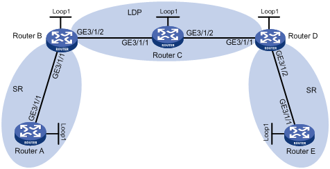
Table 4 Interface and IP address assignment
|
Device |
Interface |
IP address |
Device |
Interface |
IP address |
|
Router A |
Loop1 |
1.1.1.1/32 |
Router B |
Loop1 |
2.2.2.2/32 |
|
|
GE3/1/1 |
10.0.0.1/24 |
|
GE3/1/1 |
10.0.0.2/24 |
|
Router C |
Loop1 |
3.3.3.3/32 |
|
GE3/1/2 |
11.0.0.1/24 |
|
|
GE3/1/1 |
11.0.0.2/24 |
Router D |
Loop1 |
4.4.4.4/32 |
|
|
GE3/1/2 |
12.0.0.1/24 |
|
GE3/1/1 |
12.0.0.2/24 |
|
Router E |
Loop1 |
5.5.5.5/32 |
|
GE3/1/2 |
13.0.0.1/24 |
|
|
GE3/1/1 |
13.0.0.2/24 |
|
|
|
Procedure
1. Configure IP addresses and masks for interfaces. (Details not shown.)
2. Configure IS-IS on the routers to achieve network level connectivity and set the IS-IS cost style to wide:
# Configure Router A.
<RouterA> system-view
[RouterA] isis 1
[RouterA-isis-1] network-entity 00.0000.0000.0001.00
[RouterA-isis-1] cost-style wide
[RouterA-isis-1] quit
[RouterA] interface gigabitethernet 3/1/1
[RouterA-GigabitEthernet3/1/1] isis enable 1
[RouterA-GigabitEthernet3/1/1] quit
[RouterA] interface loopback 1
[RouterA-LoopBack1] isis enable 1
[RouterA-LoopBack1] quit
# Configure Router B.
<RouterB> system-view
[RouterB] isis 1
[RouterB-isis-1] network-entity 00.0000.0000.0002.00
[RouterB-isis-1] cost-style wide
[RouterB-isis-1] quit
[RouterB] interface gigabitethernet 3/1/1
[RouterB-GigabitEthernet3/1/1] isis enable 1
[RouterB-GigabitEthernet3/1/1] quit
[RouterB] interface gigabitethernet 3/1/2
[RouterB-GigabitEthernet3/1/2] isis enable 1
[RouterB-GigabitEthernet3/1/2] quit
[RouterB] interface loopback 1
[RouterB-LoopBack1] isis enable 1
[RouterB-LoopBack1] quit
# Configure Router C.
<RouterC> system-view
[RouterC] isis 1
[RouterC-isis-1] network-entity 00.0000.0000.0003.00
[RouterC-isis-1] cost-style wide
[RouterC-isis-1] quit
[RouterC] interface gigabitethernet 3/1/1
[RouterC-GigabitEthernet3/1/1] isis enable 1
[RouterC-GigabitEthernet3/1/1] quit
[RouterC] interface gigabitethernet 3/1/2
[RouterC-GigabitEthernet3/1/2] isis enable 1
[RouterC-GigabitEthernet3/1/2] quit
[RouterC] interface loopback 1
[RouterC-LoopBack1] isis enable 1
[RouterC-LoopBack1] quit
# Configure Router D.
<RouterD> system-view
[RouterD] isis 1
[RouterD-isis-1] network-entity 00.0000.0000.0004.00
[RouterD-isis-1] cost-style wide
[RouterD-isis-1] quit
[RouterD] interface gigabitethernet 3/1/1
[RouterD-GigabitEthernet3/1/1] isis enable 1
[RouterD-GigabitEthernet3/1/1] quit
[RouterD] interface gigabitethernet 3/1/2
[RouterD-GigabitEthernet3/1/2] isis enable 1
[RouterD-GigabitEthernet3/1/2] quit
[RouterD] interface loopback 1
[RouterD-LoopBack1] isis enable 1
[RouterD-LoopBack1] quit
# Configure Router E.
<RouterE> system-view
[RouterE] isis 1
[RouterE-isis-1] network-entity 00.0000.0000.0005.00
[RouterE-isis-1] cost-style wide
[RouterE-isis-1] quit
[RouterE] interface gigabitethernet 3/1/1
[RouterE-GigabitEthernet3/1/1] isis enable 1
[RouterE-GigabitEthernet3/1/1] quit
[RouterE] interface loopback 1
[RouterE-LoopBack1] isis enable 1
[RouterE-LoopBack1] quit
3. Configure LSR IDs on the routers:
# Configure Router A.
[RouterA] mpls lsr-id 1.1.1.1
# Configure Router B.
[RouterB] mpls lsr-id 2.2.2.2
# Configure Router C.
[RouterC] mpls lsr-id 3.3.3.3
# Configure Router D.
[RouterD] mpls lsr-id 4.4.4.4
# Configure Router E.
[RouterE] mpls lsr-id 5.5.5.5
4. Configure LDP on Router B, Router C, and Router D:
# Configure Router B.
[RouterB] mpls ldp
[RouterB-ldp] quit
[RouterB] interface gigabitEthernet3/1/2
[RouterB-GigabitEthernet3/1/2] mpls enable
[RouterB-GigabitEthernet3/1/2] mpls ldp enable
[RouterB-GigabitEthernet3/1/2] quit
# Configure Router C.
[RouterC] mpls ldp
[RouterC-ldp] quit
[RouterC] interface gigabitEthernet3/1/1
[RouterC-GigabitEthernet3/1/1] mpls enable
[RouterC-GigabitEthernet3/1/1] mpls ldp enable
[RouterC-GigabitEthernet3/1/1] quit
[RouterC] interface GigabitEthernet3/1/2
[RouterC-GigabitEthernet3/1/2] mpls enable
[RouterC-GigabitEthernet3/1/2] mpls ldp enable
[RouterC-GigabitEthernet3/1/2] quit
# Configure Router D.
[RouterD] mpls ldp
[RouterD-ldp] quit
[RouterD] interface gigabitEthernet3/1/1
[RouterD-GigabitEthernet3/1/1] mpls enable
[RouterD-GigabitEthernet3/1/1] mpls ldp enable
[RouterD-GigabitEthernet3/1/1] quit
5. Enable MPLS SR on Router A, Router B, Router D, and Router E:
# Configure Router A.
[RouterA] isis 1
[RouterA-isis-1] address-family ipv4
[RouterA-isis-1-ipv4] segment-routing mpls
[RouterA-isis-1-ipv4] quit
# Configure Router B.
[RouterB] isis 1
[RouterB-isis-1] address-family ipv4
[RouterB-isis-1-ipv4] segment-routing mpls
[RouterB-isis-1-ipv4] quit
# Configure Router D.
[RouterD] isis 1
[RouterD-isis-1] address-family ipv4
[RouterD-isis-1-ipv4] segment-routing mpls
[RouterD-isis-1-ipv4] quit
# Configure Router E.
[RouterE] isis 1
[RouterE-isis-1] address-family ipv4
[RouterE-isis-1-ipv4] segment-routing mpls
[RouterE-isis-1-ipv4] quit
6. Configure SRGBs on Router A, Router B, Router D, and Router E:
# Configure Router A.
[RouterA-isis-1] segment-routing global-block 16000 16999
[RouterA-isis-1] quit
# Configure Router B.
[RouterB-isis-1] segment-routing global-block 17000 17999
[RouterB-isis-1] quit
# Configure Router D.
[RouterD-isis-1] segment-routing global-block 18000 18999
[RouterD-isis-1] quit
# Configure Router E.
[RouterE-isis-1] segment-routing global-block 19000 19999
[RouterE-isis-1] quit
7. Configure IS-IS prefix SIDs for Router A, Router B, Router D, and Router E:
# Configure Router A.
[RouterA] interface loopback 1
[RouterA-LoopBack1] isis prefix-sid index 10
[RouterA-LoopBack1] quit
# Configure Router B.
[RouterB] interface loopback 1
[RouterB-LoopBack1] isis prefix-sid index 20
[RouterB-LoopBack1] quit
# Configure Router D.
[RouterD] interface loopback 1
[RouterD-LoopBack1] isis prefix-sid index 40
[RouterD-LoopBack1] quit
# Configure Router E.
[RouterE] interface loopback 1
[RouterE-LoopBack1] isis prefix-sid index 50
[RouterE-LoopBack1] quit
Verifying the configuration
# Display LDP LSP information on Router B.
[RouterB] display mpls ldp lsp
Status Flags: * - stale, L - liberal, B - backup, N/A - unavailable
FECs: 5 Ingress: 3 Transit: 3 Egress: 2
FEC In/Out Label Nexthop OutInterface
1.1.1.1/32 2171/-
-/2169(L)
2.2.2.2/32 2175/-
-/2170(L)
3.3.3.3/32 -/2174 11.0.0.2 GE3/1/2
2172/2174 11.0.0.2 GE3/1/2
4.4.4.4/32 -/2144 11.0.0.2 GE3/1/2
2167/2144 11.0.0.2 GE3/1/2
5.5.5.5/32 -/2162 11.0.0.2 GE3/1/2
2161/2162 11.0.0.2 GE3/1/2
# Display IS-IS SRLSP information on Router B.
[RouterB] display mpls lsp protocol isis
FEC Proto In/Out Label Out Inter/NHLFE/LSINDEX
1.1.1.1/32 ISIS 17010/3 GE3/1/1
1.1.1.1/32 ISIS -/3 GE3/1/1
2.2.2.2/32 ISIS 17020/- -
4.4.4.4/32 ISIS 17040/2144 GE3/1/2
4.4.4.4/32 ISIS -/2144 GE3/1/2
5.5.5.5/32 ISIS 17050/2162 GE3/1/2
5.5.5.5/32 ISIS -/2162 GE3/1/2
The output shows that the IS-IS SRLSP entries for Router D and Router E are using LDP outgoing labels.
