- Table of Contents
- Related Documents
-
| Title | Size | Download |
|---|---|---|
| 01-NAT configuration | 1.85 MB |
Restrictions and guidelines: NAT configuration
Interface-based NAT tasks at a glance
Configuring basic features for global NAT
About configuring basic features for global NAT
Restrictions and guidelines for global NAT configuration
Prerequisites for global NAT configuration
Configuring global NAT (for NAT and BRAS unification)
Configuring global NAT (without NAT and BRAS unification)
Configuring outbound one-to-one static NAT
Configuring outbound net-to-net static NAT
Configuring outbound dynamic NAT
Configuring NAT server mappings
Configuring common NAT server mappings on an interface
Configuring common NAT server mappings for global NAT
Configuring load sharing NAT server mappings on an interface
Configuring ACL-based NAT server mappings on an interface
Configuring port block-based NAT
Configuring static port block mapping on an interface
Configuring static port block mapping for global NAT
Configuring dynamic port block mapping on an interface
Configuring dynamic port block mapping for global NAT
Enabling extended port block report
Configuring DS-Lite B4 address translation
Restrictions and guidelines for DS-Lite B4 address translation configuration
Prerequisites for DS-Lite B4 address translation configuration
Configuring DS-Lite B4 address translation on an interface
Configuring DS-Lite B4 address translation for global NAT
Specifying a NAT processing service card
Specifying a failover group for address translation
About specifying a failover group for NAT
Specifying a failover group for a NAT address group
Specifying a failover group for a NAT port block group
Specifying a failover group for an interface that provides Easy IP
Enabling flow-triggered port block assignment
Configuring centralized backup for distributed CGN
About centralized backup for distributed CGN
Prerequisites for centralized backup configuration for distributed CGN
Configuring centralized backup for distributed CGN on a BRAS device (interface-based NAT)
Configuring centralized backup for distributed CGN on a CR (interface-based NAT)
Configuring centralized backup for distributed CGN on a BRAS device (global NAT)
Configuring centralized backup for distributed CGN on a CR (global NAT)
Configuring NAT session logging
Configuring NAT444 user logging
Configuring NAT port block assignment failure logging
Configuring NAT port allocation failure logging
Configuring threshold violation logging for port usage and port block usage
Display and maintenance commands for NAT
Example: Configuring outbound one-to-one static NAT
Example: Configuring outbound dynamic NAT (non-overlapping addresses)
Example: Configuring static NAT within a VPN instance
Example: Configuring NAT Server for external-to-internal access
Example: Configuring NAT Server for external-to-internal access through domain name
Example: Configuring NAT hairpin in C/S mode
Example: Configuring load sharing NAT Server
Example: Configuring NAT DNS mapping
Example: Configuring NAT log export to the information center
Example: Configuring NAT log export to the log server
NAT configuration examples (using CGN cards for NAT processing)
Example: Configuring outbound one-to-one static NAT
Example: Configuring outbound dynamic NAT (non-overlapping addresses)
Example: Configuring NAT static port block mapping
Example: Configuring NAT dynamic port block mapping
Example: Configuring DS-Lite B4 address translation
Example: Configuring inter-card hot backup for NAT and BRAS unification
Example: Configuring centralized backup for distributed CGN deployment
Example: Configuring extended port block report for PPPoE users
Example: Configuring unification between PPPoE user authentication and NAT for advertisement push
NAT overview
Network Address Translation (NAT) translates an IP address in the IP packet header to another IP address. Typically, NAT is configured on gateways to enable private hosts to access external networks and external hosts to access private network resources such as a Web server.
Basic NAT concepts
The following describes basic NAT concepts:
· NAT device—A device configured with NAT. Typically, NAT is configured on the edge device that connects the internal and external networks.
· NAT interface—An interface configured with NAT.
· NAT rule—A rule that NAT follows to translate addresses.
· NAT address—A public IP address used for address translation, and this address is reachable from the external network. The NAT address can be manually assigned or dynamically obtained.
· NAT entry—Stores the mapping between a private IP address and a public IP address. For more information, see "NAT entries."
· Easy IP—Uses the IP address of an interface as the NAT address. The IP address of the interface can be manually assigned or be obtained through DHCP.
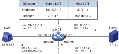
Basic NAT operating mechanism
Figure 1 shows the basic NAT operating mechanism.
2. Upon receiving a response from the server, NAT translates the destination public address to the private address, and forwards the packet to the host.
The NAT operation is transparent to the terminals (the host and the server). NAT hides the private network from the external users and shows that the IP address of the internal host is 20.1.1.1.
NAT applications
Traditional NAT
Traditional NAT is configured on the interface that connects to the public network. It translates the source IP addresses of outgoing packets and destination IP addresses of incoming packets.
Bidirectional NAT
NAT translates the source and destination IP addresses of incoming packets on the receiving interface and outgoing packets on the sending interface.
Bidirectional NAT supports active access to external network resources from internal users when the internal and external IP addresses overlap.
NAT hairpin
NAT hairpin allows internal hosts to access each other through NAT. The source and destination IP address of the packets are translated on the interface connected to the internal network.
NAT hairpin includes P2P and C/S modes:
· P2P—Allows internal hosts to access each other through NAT. The internal hosts first register their public addresses to an external server. Then, the hosts communicate with each other by using the registered IP addresses.
· C/S—Allows internal hosts to access internal servers through NAT addresses. The destination IP address of the packet going to the internal server is translated by matching the NAT Server configuration. The source IP address is translated by matching the outbound dynamic or static NAT entries.
NAT DNS mapping
The DNS server is typically on the public network. For the users on the public network to access an internal server, you can configure the NAT Server feature on the NAT interface that connects to the public network. The NAT Server maps the public IP address and port number to the private IP address and port number of the internal server. Then the public users can access the internal server through the server's domain name or public IP address.
When a user is in the private network, the user cannot access the internal server by using the domain name of the server. This is because the DNS response contains the public IP address of the server. In this case, you can configure NAT DNS mapping to solve the problem.
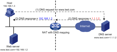
As shown in Figure 2, NAT DNS mapping works as follows:
1. The host sends a DNS request containing the domain name of the internal Web server.
2. Upon receiving the DNS response, the NAT device performs a DNS mapping lookup by using the domain name in the response. A NAT DNS mapping maps the domain name to the public IP address, public port number, and the protocol type for the internal server.
3. If a match is found, the NAT continues to compare the public address, public port number, and the protocol type with the NAT Server configuration. The NAT Server configuration maps the public IP address and port number to the private IP address and port number for the internal server.
4. If a match is found, NAT translates the public IP address in the response into the private IP address of the Web server.
5. The internal host receives the DNS response, and obtains the private IP address of the Web server.
NAT control
You can use ACLs to implement NAT control. The match criteria in the ACLs include the source IP address, source port number, destination IP address, destination port number, transport layer protocol, user group, and VPN instance. Only packets permitted by an ACL are processed by NAT.
NAT translation methods
Static NAT
Static NAT creates a fixed mapping between a private address and a public address. It supports connections initiated from internal users to external network and from external users to the internal network. Static NAT applies to regular communications.
Dynamic NAT
Dynamic NAT uses an address pool to translate addresses. It applies to the scenario where a large number of internal users access the external network.
NO-PAT
Not Port Address Translation (NO-PAT) translates a private IP address to an IP public address. The public IP address cannot be used by another internal host until it is released.
NO-PAT supports all IP packets.
PAT
Port Address Translation (PAT) translates multiple private IP addresses to a single public IP address by mapping the private IP address and source port to the public IP address and a unique port. PAT supports TCP and UDP packets, and ICMP request packets.
Figure 3 PAT operation
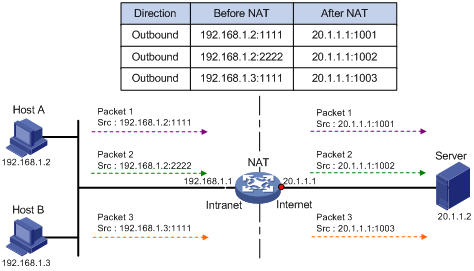
As shown in Figure 3, PAT translates the source IP addresses of the three packets to the same IP public address and translates their port numbers to different port numbers. Upon receiving a response, PAT translates the destination address and port number of the response, and forwards it to the target host.
PAT supports the following mappings:
· Endpoint-Independent Mapping (EIM)—Uses the same IP and port mapping (EIM entry) for packets from the same source IP and port to any destinations. EIM allows external hosts to initiate connections to the translated IP addresses and ports of internal hosts. It allows internal hosts behind different NAT gateways to access each other.
· Connection-Dependent Mapping—Uses the same IP and port mapping for packets of the same connection. Different IP and port mappings are used for different connections although the connections might have the same source IP address and port number. It is secure because it allows an external host to access an internal host only under the condition that the internal host has previously accessed the external host.
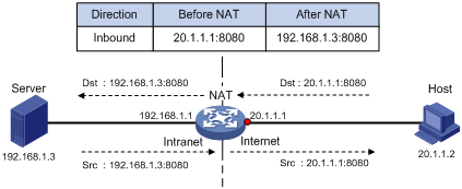
NAT Server
The NAT Server feature maps a public address and port number to the private IP address and port number of an internal server. This feature allows servers in the private network to provide services for external users.
Figure 4 shows how NAT Server works:
1. Upon receiving a request from the host, NAT translates the public destination IP address and port number to the private IP address and port number of the internal server.
2. Upon receiving a response from the server, NAT translates the private source IP address and port number to the public IP address and port number.
Port block-based NAT
Port block-based NAT is a PAT translation based on port ranges. It maps multiple private IP addresses to one public IP address and uses a different port block for each private IP address. For example, the private IP address 10.1.1.1 of an internal host is mapped to the public IP address 202.1.1.1 and port block 10001 to 10256. When the internal host accesses public hosts, the source IP address 10.1.1.1 is translated to 202.1.1.1, and the source ports are translated to ports in the port block 10001 to 10256.
Port block-based NAT includes static and dynamic mappings. It applies to NAT444 and DS-Lite networks.
Static port block mapping
The NAT gateway computes a static port block mapping before address translation. The mapping is between a private IP address and a public IP address with a port block.
When an internal user initiates a connection to the external network, the system performs the following operations:
· Locates a static mapping based on the private IP address of the user and obtains the public IP address and the port block in the mapping.
· Selects a public port number in the port block.
· Translates the private IP address to the public IP address and assigns the selected public port number.
The NAT gateway uses private IP addresses, public IP addresses, a port range, and a port block size to compute static mappings:
1. Divides the port range by the port block size to get the number of available port blocks for each public IP address.
This value is the base number for mapping.
2. Sorts the port blocks in ascending order of the start port number in each block.
3. Sorts the private IP addresses and the public IP addresses separately in ascending order.
4. Maps the first base number of private IP addresses to the first public IP address and its port blocks in ascending order.
For example, the number of available port blocks of each public IP address is m. The first m private IP addresses are mapped to the first public IP address and the m port blocks in ascending order. The next m private IP addresses are mapped to the second IP address and the m port blocks in ascending order. The other static port block mappings are created by analogy.
Dynamic port block mapping
In the NAT and BRAS unification scenario, the device operates as follows:
1. When a user passes authentication, the device looks up NAT configuration on all interfaces for a matching ACL for the user traffic.
2. If a matching ACL in all NAT configuration is found, the device assigns public IP address and a port block to the user, and creates a dynamic port block mapping.
3. After the user goes offline, the device reclaims the port block and deletes the dynamic port block mapping.
In other scenarios, when an internal user initiates a connection to the external network, the dynamic port block-based NAT operates as follows:
4. Uses ACLs to implement translation control. It processes only packets that match an ACL permit rule.
5. Creates a mapping from the internal user's private IP address to a public IP address and a port block.
6. Translates the private IP address to the public IP address, and the source ports to ports in the selected port block for subsequent connections from the private IP address.
7. Withdraws the port block and deletes the dynamic port block mapping when all connections from the private IP address are disconnected.
Dynamic port block mapping supports port block extending. If the ports in the port block for a private address are all occupied, dynamic port block mapping translates the source port to a port in an extended port block.
NAT entries
NAT session entry
NAT creates a NAT session entry for a session and creates an address mapping for the first packet in the session.
A NAT session entry contains extended NAT information, such as interface and translation method. Subsequent packets of the session are translated by using this entry.
· If the direction of the subsequent packets is the same as the direction of the first translated packet, NAT performs the source and destination address translation the same as the first packet.
· If the direction of the subsequent packets is opposite to the direction of the first translated packet, NAT perform reverse address translation. For example, if the source address of the first packet is translated, then the destination address of the subsequent packets is translated.
The session management module maintains the updating and aging of NAT session entries. For information about session management, see Security Configuration Guide.
EIM entry
If EIM is configured on the NAT device, the PAT mode will first create a NAT session entry, and then an 3-tuple EIM entry. The EIM entry maps a private address/port to a public address/port. The EIM entry ensures:
· Subsequent new connections originating from the same source IP and port uses the same translation as the initial connection.
· Translates the address for new connections initiated from external hosts to the NAT address and port number based on the EIM entry.
An EIM entry ages out after all related NAT session entries age out.
NO-PAT entry
A NO-PAT entry maps a private address to a public address. The same mapping applies to subsequent connections originating from the same source IP.
A NO-PAT entry can also be created during the ALG process for NAT. For information about NAT ALG, see "NAT ALG."
A NO-PAT entry ages out after all related NAT session entries age out.
Port block-based entry
A port block-based entry maps a private IP address to a public IP address and a port block.
Port block-based entries include static and dynamic port block mappings. For information about these mappings, see "Static port block mapping" and "Dynamic port block mapping."
VRF-aware NAT
VRF-aware NAT allows users from the same VRF (VPN instance) to access external networks and to access each other.
1. Upon receiving a request from a user in a VRF to an external network, NAT performs the following tasks:
? Translates the private source IP address and port number to a public IP address and port number.
? Records the VRF information, such as the VRF name.
2. When a response packet arrives, NAT performs the following tasks:
? Translates the destination public IP address and port number to the private IP address and port number.
? Forwards the packet to the target VRF.
The NAT Server feature supports VRF-aware NAT for external users to access the servers in a VPN instance. For example, to enable a host at 10.110.1.1 in VPN 1 to provide Web services for Internet users, configure NAT Server to use 202.110.10.20 as the public IP address of the Web server.
NAT ALG
NAT ALG (Application Level Gateway) translates address or port information in the application layer payloads to ensure connection establishment.
For example, an FTP application includes a data connection and a control connection. The IP address and port number for the data connection depend on the payload information of the control connection. This requires NAT ALG to translate the address and port information for data connection establishment.
CGN
About CGN
Carrier Grade NAT (CGN), also called Large-scale NAT (LSN), is typically deployed in the ISP network. Traditionally NAT is deployed on the CPE devices for address translation of few users. CGN translates addresses for a large number of users by installing CGN cards on devices such as the BRAS devices. Meanwhile, CGN supports more concurrent users, higher performance, and better user tracing.
CGN is applicable to multiple scenarios, such as NAT444 and DS-Lite.
The CGN card refers to CGN-capable card IM-MSUX.
CGN deployment
CGN deployment falls into the following types based on the CGN card location:
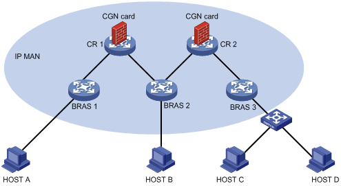
· Centralized CGN deployment—A CGN-capable device is close to or at the core of MAN, typically deployed on a CR device. To implement the deployment, you can connect devices with CGN cards installed to the CR devices (Figure 5) or install CGN cards on the CR devices (Figure 6).
This deployment is applicable to a network with a small number of users and traffic.
Figure 5 Connecting CR devices to devices with CGN cards installed

Figure 6 Installing CGN cards on the CR devices
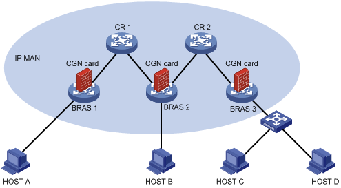
· Distributed CGN deployment—A CGN-capable device is close to or at the edge of MAN, typically deployed on a BRAS device. As is shown in Figure 7, to implement distributed CGN deployment, a CGN card is installed on each BRAS device.
Distributed CGN deployment is applicable to a network with a large number of users and traffic.
Figure 7 Distributed CGN deployment
CGN backup
The CGN backup feature ensures service continuity and provides high availability for the ISP network.
Centralized backup for distributed CGN deployment
This backup plan allows a centralized CGN device to provide backup services for distributed CGN deployment. When a distributed CGN device fails, the centralized CGN device provides address translation.
As shown in Figure 8, the BRAS device provides AAA for users, the CR device groups and forwards data traffic. Traffic is NATed by the CGN card on the BRAS device. When the CGN card on the BRAS device fails, traffic is redirected to the CGN card on the CR device for NAT processing.
Figure 8 Centralized backup for distributed CGN deployment

Traffic is redirected to the CGN card on the CR device by the following methods:
· BRAS routing—The BRAS sends the traffic to the CR based on the routing table, as is shown in Figure 9. On the CAR, the QoS policy redirects the traffic to the CGN card. After the CGN card on the BRAS device recovers, the QoS policy on the BRAS takes effect again and directs traffic to its CGN card.
Figure 9 Centralized backup for distributed CGN deployment (through BRAS routing)

· GRE tunneling between BRAS and CR—Traffic is redirected to the next hop by the QoS policy on the BRAS device and then sent to the CR through GRE tunneling. On the CR, traffic is redirected to the CGN card through a QoS policy. After the CGN card on the BRAS device recovers, the QoS policy on the BRAS directs traffic to the failover group on the BRAS device. The traffic is NATed on the primary node (CGN card) of the failover group.
Figure 10 Centralized backup for distributed CGN (through GRE tunneling)
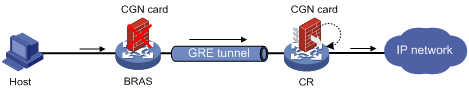
If you use the BRAS routing method, make an overall network planning on private IP addresses because the private IP routes might enter MAN. The GRE tunneling method can avoid this issue, but it requires a dedicated GRE tunnel and a QoS policy for redirecting traffic to an interface on the CR. For more information about GRE tunneling, see "Configuring GRE."
Intra-system CGN backup
This backup plan refers to the backup among multiple CGN cards on the same device. It supports the warm backup method that backs up port block entries but no session entries. After switchover, public IP-private IP mappings do not change, but session re-establishment is not needed.
You can create one, two, or multiple failover groups to implement inter-card backup for centralized CGN deployment and distributed CGN deployment. For more information about failover groups, see High Availability Configuration Guide.
For example, use two CGN cards on the BRAS to create one failover group as is shown in Figure 11. The primary node CGN 1 in the failover group provides NAT services. When the primary node operates incorrectly, as is shown in Figure 12, the secondary node CGN 2 takes over to provide NAT services.
Figure 11 Inter-card CGN backup (when CGN 1 operates correctly)
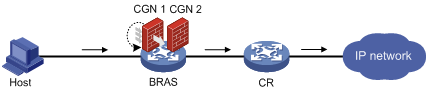
Figure 12 Inter-card CGN backup (when CGN 2 operates incorrectly)

NAT444
About NAT444
NAT444 provides carrier-grade NAT by unifying the NAT444 gateway, AAA server, and log server. NAT444 introduces a second layer of NAT on the carrier side, with few changes on the customer side and the application server side. With port block assignment, NAT444 supports user tracking. It has become a preferred solution for carriers in transition to IPv6.
The NAT444 solution can be centralized and distributed deployment.
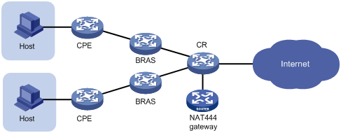
Centralized NAT444 deployment
Centralized NAT444 deployment is implemented by installing a NAT service card on the CR device or by connecting a NAT444 device to the CR.
As shown in Figure 13, when an internal user accesses the external network, NAT444 is implemented as follows:
1. The CPE device performs the first NAT.
2. After the user passes AAA authentication on the BRAS device, this user is assigned a private IP address.
3. When the packet destined to the external network, the NAT444 gateway performs the second NAT.
Figure 13 Centralized NAT444 deployment
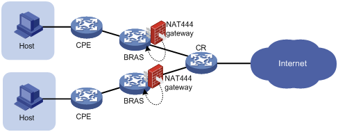
Distributed NAT444 deployment
Distributed NAT444 deployment is implemented by installing a NAT service card on the BRAS device. This deployment also requires the unification of NAT444 gateway and the BRAS device. To unify the NAT444 gateway and BRAS device, specify the user address type in the ISP domain.
As shown in Figure 14, the NAT444 gateway and BRAS device function as follows after the unification:
1. After a user passes authentication and obtains a private address, the NAT444 gateway immediately assigns a public IP address and a port block to the user.
If the NAT444 resources have been used up, the BRAS logs off the user, which ensures accurate accounting on the AAA server.
2. The NAT444 gateway sends the port block mapping to the BRAS device.
3. The BRAS device records the mapping and reports it to the AAA server.
The AAA server maintains one mapping for each online user until the user goes offline. The unification ensures that the AAA server maintains mappings for all users and provides user tracing without requiring an extra log server.
Only the unification between the NAT444 gateway and the PPPoE or IPoE service is supported in the current software version.
Figure 14 Distributed NAT444 deployment
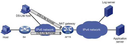
NAT in the DS-Lite network
Dual Stack Lite (DS-Lite) is a combination of the tunneling and NAT technologies. NAT translates the private IPv4 addresses of the IPv4 hosts before the hosts reach the IPv4 public network. For more information about DS-Lite, see "IPv4 over IPv6 tunneling."
As the gateway of the private network, the B4 element is responsible for the encapsulation and de-encapsulation of tunneled packets. DS-Lite B4 address translation is configured on the AFTR and performs port block-based translation based on the IPv6 address of the B4 element. DS-Lite B4 address translation dynamically maps a public IPv4 address and a port block to the IPv6 address of the B4 element. Hosts behind the B4 element use the mapped public IPv4 address and port block to access the public IPv4 network.
DS-Lite B4 address translation supports user tracing based on the port block.
Figure 15 DS-Lite B4 address translation
Configuring NAT
Restrictions and guidelines: NAT configuration
According to the application scope of NAT rules, NAT supports the following application types:
· Interface-based NAT—Uses NAT rules configured on a per interface basis to translate packets.
· Global NAT—Uses NAT rules configured on a per NAT instance basis to translate packets. The packets are redirected to the NAT instance by using a QoS policy.
Interface-based NAT and global NAT are mutually exclusive. To configure global NAT, you must first delete existing NAT configurations on all interfaces. To configure interface-based NAT, you must first delete all existing NAT instance configurations.
The general restrictions and guidelines are as follows:
· You can use an ACL in a NAT rule to identify the IP addresses to be translated. The match criteria include the source IP address, source port number, destination IP address, destination port number, transport layer protocol, user group, and VPN instance. For more information about ACLs, see ACL and QoS Configuration Guide.
· If you perform all the translation methods on an interface, the NAT rules are sorted in the following descending order:
a. NAT Server.
b. Static NAT.
c. NAT static port blocking mapping.
d. Dynamic NAT, NAT dynamic port block mapping, and DS-Lite B4 address translation.
Dynamic NAT, NAT dynamic port block mapping, and DS-Lite B4 address translation have the same priority. Dynamic NAT rules and NAT dynamic port block mapping rules are sorted in descending order of ACL numbers and are effective for IPv4 packets.
DS-Lite B4 address translation rules are effective for IPv6 packets.
· After you apply the NAT configuration, the dynamic configuration of an ACL rule in a QoS policy affects only the subsequent traffic that is not processed by NAT. Traffic that have been processed by NAT is not affected.
· In a DS-Lite network, make sure the MTU of the physical output interface of the DS-Lite tunnel is at least 40 bytes higher than that of the DS-Lite tunnel interface. Otherwise, packet forwarding will fail.
· VRF-NAT is not supported on CSPC cards (except CSPC-GE16XP4L-E, CSPC-GE24L-E, CSPC-GP24GE8XP2L-E) and CMPE-1104 cards.
· If QinQ termination is enabled on a subinterface on a CSPC card (except CSPC-GE16XP4L-E, CSPC-GE24L-E, CSPC-GP24GE8XP2L-E) or CMPE-1104 card with port capacity no larger than 80G, the subinterface cannot be the output interface for NATed traffic. The port capacity for a card refers to the total speed of all the interfaces on the card. For example, the port capacity for CSPC-GP24XP2LB is calculated as follows:
2 x 10 G + 24 x 1 G = 44 G
· If the QoS redirecting traffic to a slot action changes to another redirecting action or vice versa, use the reset ip fast-forwarding cache slot command to clear the fast forwarding information for the slot.
· CSPC-GE16XP4L-E, CSPC-GE24L-E, CSPC-GP24GE8XP2L-E cards, CSPEX cards, and CEPC cards support address translation only between public networks or within the same VPN instance.
· CSPC cards (except CSPC-GE16XP4L-E, CSPC-GE24L-E, and CSPC-GP24GE8XP2L-E) and CMPE-1104 cards support address translation only between public networks.
When you configure BRAS unification, follow these restrictions and guidelines:
· Supported user address types are private IPv4 address, private-DS address, and DS-Lite address.
· The NAT port block configuration can be modified only after all users go offline.
Table 1 describes required ACL rule parameters when you configure an ACL for NAT in a specific scenario. You must specify a minimum of one required parameter.
Table 1 ACL rule parameters for NAT in different scenarios
|
Scenarios |
Required parameters |
|
NAT and BRAS unification |
Source IP address, VPN instance, and user group. |
|
NAT, BRAS, and load balancing unification |
User group |
|
Traffic-triggered port block assignment |
Source IP address, VPN instance, source port, protocol type, and user group. |
Global NAT tasks at a glance
To configure global NAT, perform the following tasks:
1. Configuring basic features for global NAT
2. Configuring outbound dynamic NAT for global NAT
3. Configuring common NAT server mappings for global NAT
4. Configuring static port block mapping for global NAT
5. Configuring dynamic port block mapping for global NAT
6. Configuring DS-Lite B4 address translation for global NAT
7. (Optional.) Configuring NAT hairpin
8. (Optional.) Configuring NAT DNS mapping
9. (Optional.) Configuring NAT ALG
10. (Optional.) Configuring NAT logging
Interface-based NAT tasks at a glance
To configure NAT on an interface, perform the following tasks:
1. Configuring a translation method on an interface
? Configuring outbound dynamic NAT for interface-based NAT
? Configuring common NAT server mappings on an interface
? Configuring load sharing NAT server mappings on an interface
? Configuring ACL-based NAT server mappings on an interface
? Configuring static port block mapping on an interface
? Configuring dynamic port block mapping on an interface
? Enabling extended port block report
? Configuring DS-Lite B4 address translation on an interface
2. Specifying a slot for processing NAT services.
Choose one of the following options to configure as needed:
? Specifying a NAT processing service card
To use a NAT-capable service card for NAT service processing, specify this service card on an interface with NAT configured.
? Specifying a failover group for address translation
To enable the specified CGN card to process NAT service, you must also configure QoS policies.
3. (Optional.) Configuring centralized backup for distributed CGN
a. Configuring centralized backup for distributed CGN on a BRAS device (interface-based NAT)
b. Configuring centralized backup for distributed CGN on a CR (interface-based NAT)
4. (Optional.) Configuring NAT hairpin
5. (Optional.) Configuring NAT DNS mapping
6. (Optional.) Configuring NAT ALG
7. (Optional.) Configuring NAT logging
Configuring basic features for global NAT
About configuring basic features for global NAT
Global NAT is applicable to a network with unfixed output interfaces. You do not need to change the global NAT configuration if the packet output interface changes.
Because a CGN card does not have interfaces for service processing, a QoS policy is required to redirect traffic from the egress interface card to the CGN card. Global NAT is implemented as follows:
· A service instance group is associated with a NAT instance and a failover group that contains CGN card nodes. For more information about configuring service instance groups and failover groups, see High Availability Configuration Guide.
· A QoS policy is used to redirect the traffic to the NAT instance. The primary node in the failover group performs address translation for traffic that matches the rules in the NAT instance.
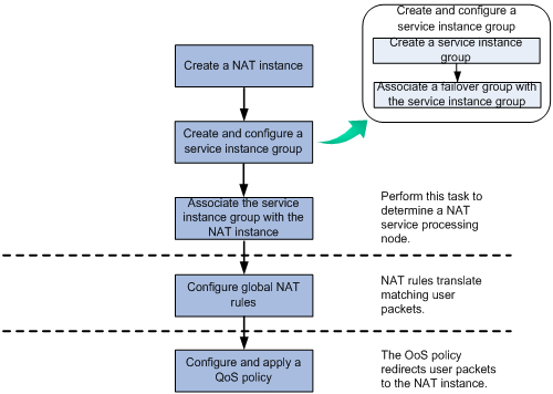
Analysis
In the NAT and BRAS unification scenario, the access device assigns an online user a load-sharing user group and a NAT instance. The device then uses a QoS policy to redirect user packets of the load-sharing user group to a NAT instance. NAT translates the user packets that match address translation rules in the NAT instance.
Figure 16 describes how to configure NAT in a NAT and BRAS unification scenario.
Figure 16 Global NAT configuration in the NAT and BRAS unification scenario

In a scenario without NAT and BRAS unification, the device uses a QoS policy to redirect user traffic to a NAT instance. NAT translates user traffic that match address translation rules in the NAT instance.
Figure 17 describes how to configure NAT in scenarios without the NAT and BRAS unification.
Figure 17 Global NAT configuration in scenarios without NAT and BRAS unification
Restrictions and guidelines for global NAT configuration
A NAT instance takes effect when the following requirements are met:
· The NAT instance is associated with a service instance group.
· The service instance group is associated with a failover group and the primary node in the failover group can correctly process services.
In NAT and BRAS unification scenarios, you cannot delete a NAT instance if the NAT instance has been bound to the user group of an online user.
Prerequisites for global NAT configuration
Before you configure a NAT instance, create a service instance group, and associate the service instance group with a failover group. For more information about configuring service instance groups and failover groups, see High Availability Configuration Guide.
Configuring global NAT (for NAT and BRAS unification)
Restrictions and guidelines
The traffic behavior in the QoS policy and the load-sharing user group in the ISP domain must be bound to the same NAT instance.
Procedure
1. Enter system view.
system-view
2. Create a NAT instance and enter its view.
nat instance instance-name id id
3. Associate a service instance group with the NAT instance.
service-instance-group service-instance-group-name
By default, the NAT instance does not have any associated service instance groups.
4. Configure NAT rules. Choose the options to configure as needed:
? Configure DS-Lite B4 address translation.
For more information, see "Configuring DS-Lite B4 address translation for global NAT."
? Configure static port block mapping.
For more information, see "Configuring static port block mapping for global NAT."
? Configure dynamic port block mapping.
For more information, see "Configuring dynamic port block mapping for global NAT."
5. Return to system view.
quit
6. Bind the load-sharing user group with the NAT instance.
a. Create an ISP domain and enter its view.
domain name isp-name
b. Specify a load-sharing user group and bind it to the NAT instance.
user-group name group-name bind nat-instance instance-name
For more information about these commands, see AAA configuration in Security Configuration Guide.
7. Return to system view.
quit
8. Configure and apply a QoS policy.
a. Configure an ACL.
You must specify the user-group keyword in ACL rules to identify user packets of user groups.
For more information about ACL, see ACL and QoS Configuration Guide.
b. Define a NAT traffic class with the ACL as the match criterion, define a traffic behavior, and bind the traffic behavior with the NAT instance.
c. Create a QoS policy to associate the traffic class with the traffic behavior.
d. Apply the QoS policy to the inbound direction of user traffic.
For more information about QoS commands, see QoS policy configuration in ACL and QoS Configuration Guide.
Configuring global NAT (without NAT and BRAS unification)
1. Enter system view.
system-view
2. Create a NAT instance and enter its view.
nat instance instance-name id id
3. Associate a service instance group with the NAT instance.
service-instance-group service-instance-group-name
By default, the NAT instance does not have any associated service instance groups.
4. Configure NAT rules. Choose the options to configure as needed:
? Configure outbound dynamic NAT.
For more information, see "Configuring outbound dynamic NAT for global NAT."
? Configure DS-Lite B4 address translation.
For more information, see "Configuring DS-Lite B4 address translation for global NAT."
? Configure NAT444 port block mapping.
For more information, see "Configuring static port block mapping for global NAT" and "Configuring dynamic port block mapping for global NAT."
? Configure common NAT Server.
For more information, see "Configuring common NAT server mappings for global NAT."
5. Return to system view.
quit
6. Configure and apply a QoS policy.
a. Configure an ACL.
The ACL is used to match source IP address of the packets. For more information about ACL, see ACL and QoS Configuration Guide.
b. Define a NAT traffic class with the ACL as the match criterion, define a traffic behavior, and bind the traffic behavior with the NAT instance.
c. Create a QoS policy to associate the traffic class with the traffic behavior.
d. Apply the QoS policy to the inbound direction of user traffic.
For more information about QoS commands, see QoS policy configuration in ACL and QoS Configuration Guide.
Configuring static NAT
Restrictions and guidelines
If you use a failover group in an outbound static NAT mapping, make sure the failover group has the CGN cards as the nodes. For more information about failover groups, see High Availability Configuration Guide.
The nat static enable command and the nat instance command are mutually exclusive.
Prerequisites
Configure an ACL to identify the IP addresses to be translated. For more information about ACLs, see ACL and QoS Configuration Guide.
Configuring outbound one-to-one static NAT
About outbound one-to-one static NAT
For address translation from a private IP address to a public IP address, configure outbound one-to-one static NAT on the interface connected to the external network.
· When the source IP address of a packet from the private network matches the local-ip, the source IP address is translated into the global-ip.
· When the destination IP address of a packet from the public network matches the global-ip, the destination IP address is translated into the local-ip.
Procedure
1. Enter system view.
system-view
2. Configure a one-to-one mapping for outbound static NAT.
nat static outbound local-ip [ vpn-instance local-vpn-instance-name ] global-ip [ vpn-instance global-vpn-instance-name ] [ acl { ipv4-acl-number | name ipv4-acl-name } [ reversible ] ] [ failover-group group-name ]
3. Enter interface view.
interface interface-type interface-number
4. Enable static NAT on the interface.
nat static enable
By default, static NAT is disabled.
Configuring outbound net-to-net static NAT
About outbound net-to-net static NAT
For address translation from a private network to a public network, configure outbound net-to-net static NAT on the interface connected to the external network.
· When the source IP address of a packet from the private network matches the private address range, the source IP address is translated into a public address in the public address range.
· When the destination IP address of a packet from the public network matches the public address range, the destination IP address is translated into a private address in the private address range.
Procedure
1. Enter system view.
system-view
2. Configure a net-to-net mapping for outbound static NAT.
nat static outbound net-to-net local-start-address local-end-address [ vpn-instance local-vpn-instance-name ] global global-network { mask-length | mask } [ vpn-instance global-vpn-instance-name ] [ acl { ipv4-acl-number | name ipv4-acl-name } [ reversible ] ] [ failover-group group-name ]
3. Enter interface view.
interface interface-type interface-number
4. Enable static NAT on the interface.
nat static enable
By default, static NAT is disabled.
Configuring dynamic NAT
Restrictions and guidelines
You can configure multiple inbound or outbound dynamic NAT rules.
· A NAT rule with an ACL takes precedence over a rule without any ACL.
· If two ACL-based dynamic NAT rules are configured, the rule with the higher ACL number has higher priority.
· In the NAT and BRAS unification scenario, the device goes through NAT rules on all the interfaces in ascending order of interface index after a user passes authentication. When a packet matches an ACL permit rule on an interface with smaller interface index, the matching process stops. To avoid incorrect traffic matching and translation, configure ACL rules in the NAT rules appropriately.
Prerequisites
Before configuring dynamic NAT, you must perform the following tasks:
· Configure an ACL to identify the IP addresses to be translated. For more information about ACLs, see ACL and QoS Configuration Guide.
· Determine whether to enable the Easy IP feature. If you use the IP address of an interface as the NAT address, you are configuring Easy IP.
· Determine a public IP address pool for address translation.
· Determine whether to translate port numbers. Use NO-PAT to translate only IP addresses and PAT to translate both IP addresses and port numbers.
Configuring outbound dynamic NAT
About outbound dynamic NAT
To translate private IP addresses into public IP addresses, configure outbound dynamic NAT on the interface connected to the external network.
Restrictions and guidelines
Outbound dynamic NAT is typically configured on the interface connected to the external network.
The interface-based outbound dynamic NAT cannot coexist with the nat instance command on the same device.
Configuring outbound dynamic NAT for interface-based NAT
1. Enter system view.
system-view
2. (Optional.) Specify the Endpoint-Independent Mapping mode for outbound dynamic PAT.
nat mapping-behavior endpoint-independent { tcp [ tcp-5-tuple ] | udp [ udp-5-tuple ] } *
The default mapping mode is Connection-Dependent Mapping.
This command applies to the devices that support three-tuple EIM entries, and takes effect only on outbound PAT.
3. Create a NAT address group and enter its view.
nat address-group group-id
4. Add an address range to the address group.
address start-address end-address
By default, no address ranges exist.
You can add multiple address ranges to an address group, but the address ranges must not overlap.
5. (Optional.) Set the maximum number of ports that can be assigned for a protocol.
port-limit { icmp | tcp | total | udp } number
By default, no upper limit is set for a protocol.
6. Return to system view.
quit
7. Enter interface view.
interface interface-type interface-number
8. Configure outbound dynamic NAT on the interface. Choose the options to configure as needed:
? Configure NO-PAT.
nat outbound [ ipv4-acl-number | name ipv4-acl-name ] address-group group-id [ vpn-instance vpn-instance-name ] no-pat [ reversible ]
? Configure PAT.
nat outbound [ ipv4-acl-number | name ipv4-acl-name ] [ address-group group-id ] [ vpn-instance vpn-instance-name ] [ port-preserved ]
You can configure multiple outbound dynamic NAT rules on an interface.
|
Parameter |
Description |
|
address-group |
If you do not specify this keyword, the IP address of the interface is used as the NAT address. Easy IP is implemented. |
|
no-pat reversible |
If you specify these keywords, you enable reverse address translation. Reverse address translation uses existing NO-PAT entries to translate the destination address for connections actively initiated from the external network to the internal network. The destination address is translated into the private IP address in the matching NO-PAT entry. |
Configuring outbound dynamic NAT for global NAT
1. Enter system view.
system-view
2. (Optional.) Specify the Endpoint-Independent Mapping mode for outbound dynamic PAT.
nat mapping-behavior endpoint-independent { tcp [ tcp-5-tuple ] | udp [ udp-5-tuple ] } *
The default mapping mode is Connection-Dependent Mapping.
This command takes effect only on outbound dynamic PAT.
3. Create a NAT address group and enter its view.
nat address-group group-id
4. Add an address range to the address group.
address start-address end-address
By default, an address group does not have any address ranges.
You can add multiple address ranges to an address group, but the address ranges cannot overlap.
5. (Optional.) Set the maximum number of ports that can be assigned for a protocol.
port-limit { icmp | tcp | total | udp } number
By default, no upper limit is set for a protocol.
6. Return to system view.
quit
7. Create a NAT instance and enter its view.
nat instance instance-name id id
8. Configure outbound dynamic NAT for global NAT.
nat outbound [ ipv4-acl-number | name ipv4-acl-name ] address-group group-id [ vpn-instance vpn-instance-name ] [ no-pat [ reversible ] | [ port-preserved ] ]
By default, outbound dynamic NAT for global NAT is not configured.
Outbound dynamic NAT translation rules in different NAT instances cannot use the same NAT address group.
Configuring NAT server mappings
About NAT server mappings
Typically, the NAT Server feature is configured on the NAT device to allow servers in the private network to provide services for external users. It maps a public IP address and port number to the private IP address and port number of the internal server.
The NAT Server feature can be implemented by the following methods:
· Common NAT server mappings—Maps the private IP address and the port number of the internal server to a public IP address and a port number. This method allows external hosts to access the internal server by using the specified public IP address.
· Load sharing NAT server mappings—You can add multiple internal servers to an internal server group so that these servers provide the same service for external hosts. The NAT device chooses one internal server based on the weight and number of connections of the servers to respond to a request from an external host to the public address of the internal server group.
· ACL-based NAT server mappings—An extension of common NAT server mapping. A common NAT server mapping maps the private IP address of the internal server to a single public IP address. An ACL-based NAT server mapping the private IP address of the internal server to a set of public IP addresses defined by an ACL. If the destination address of a packet matches a permit rule in the ACL, the destination address is translated into the private IP address of the internal server.
Restrictions and guidelines
Interface-based NAT server mappings cannot coexist with the nat instance command on the same device.
Configuring common NAT server mappings on an interface
Restrictions and guidelines
Typically, interface-based NAT server mappings are configured on the interface connected to the external network.
Procedure
1. Enter system view.
system-view
2. Enter interface view.
interface interface-type interface-number
3. Configure common NAT server mappings. Choose the options to configure as needed:
? A single public address with a single or no public port:
nat server [ protocol pro-type ] global { global-address | current-interface | interface interface-type interface-number } [ global-port ] [ vpn-instance global-vpn-instance-name ] inside local-address [ local-port ] [ vpn-instance local-vpn-instance-name ] [ acl { ipv4-acl-number | name ipv4-acl-name } ] [ reversible ]
? A single public address with consecutive public ports:
nat server protocol pro-type global { global-address | current-interface | interface interface-type interface-number } global-port1 global-port2 [ vpn-instance global-vpn-instance-name ] inside { { local-address | local-address1 local-address2 } local-port | local-address local-port1 local-port2 } [ vpn-instance local-vpn-instance-name ] [ acl { ipv4-acl-number | name ipv4-acl-name } ]
? Consecutive public addresses with a single or no public port:
nat server protocol pro-type global global-address1 global-address2 [ global-port ] [ vpn-instance global-vpn-instance-name ] inside { local-address | local-address1 local-address2 } [ local-port ] [ vpn-instance local-vpn-instance-name ] [ acl { ipv4-acl-number | name ipv4-acl-name } ]
? Consecutive public addresses with a single public port:
nat server protocol pro-type global global-address1 global-address2 global-port [ vpn-instance global-vpn-instance-name ] inside local-address local-port1 local-port2 [ vpn-instance local-vpn-instance-name ] [ acl { ipv4-acl-number | name ipv4-acl-name } ]
You can configure multiple NAT Server mappings on an interface.
Configuring common NAT server mappings for global NAT
1. Return to system view.
quit
2. Create a NAT instance and enter its view.
nat instance instance-name id id
3. Associate a service instance group with the NAT instance.
service-instance-group service-instance-group-name
By default, the NAT instance does not have any associated service instance groups.
4. Configure common NAT server mappings. Choose the options to configure as needed:
? A single public address with no public port:
nat server global global-address [ vpn-instance global-vpn-instance-name ] inside local-address [ vpn-instance local-vpn-instance-name ] [ reversible ]
? A single public address with a single public port:
nat server protocol pro-type global global-address [ global-port ] [ vpn-instance global-vpn-instance-name ] inside local-address [ local-port ] [ vpn-instance local-vpn-instance-name ] [ reversible ]
? NAT interface address as the public address with a single public port:
nat server protocol pro-type global interface interface-type interface-number global-port [ vpn-instance global-vpn-instance-
name ] inside local-address local-port [ vpn-instance local-vpn-instance-name ] [ reversible ]
Configuring load sharing NAT server mappings on an interface
Restrictions and guidelines
When you configure load shared internal servers, you must make sure a user uses the same public address and public port to access the same service on an internal server. For this purpose, make sure value N in the following mappings is equal to or less than the number of servers in the internal server group:
· One public address and N consecutive public port numbers are mapped to one internal server group.
· N consecutive public addresses and one public port number are mapped to one internal server group.
Procedure
1. Enter system view.
system-view
2. Create a NAT Server group and enter its view.
nat server-group group-id
3. Add an internal server into the group.
inside ip inside-ip port port-number [ weight weight-value ]
You can add multiple internal servers to a group.
4. Return to system view.
quit
5. Enter interface view.
interface interface-type interface-number
6. Configure load sharing NAT Server.
nat server protocol pro-type global { { global-address | current-interface | interface interface-type interface-number } { global-port | global-port1 global-port2 } | global-address1 global-address2 global-port } [ vpn-instance global-vpn-instance-name ] inside server-group group-id [ vpn-instance local-vpn-instance-name ] [ acl { ipv4-acl-number | name ipv4-acl-name } ]
You can configure multiple load sharing NAT Server mappings on an interface.
Configuring ACL-based NAT server mappings on an interface
1. Enter system view.
system-view
2. Enter interface view.
interface interface-type interface-number
3. Configure ACL-based NAT Server.
nat server global { ipv4-acl-number | name ipv4-acl-name } inside local-address [ local-port ] [ vpn-instance local-vpn-instance-name ]
You can configure multiple NAT Server mappings on an interface.
Configuring port block-based NAT
About port block-based NAT
Port block-based NAT provides outbound address translation, and it is configured on the interface connected to the public network. For example in NAT444 application, by configuring port block-based NAT address translation on the NAT444 gateway, multiple private IP addresses are mapped to one public IP address and a different port block is used for each private IP address
Restrictions and guidelines
To configure dynamic port block mapping, you must configure port block parameters in the NAT address group.
Interface-based static or dynamic port block mappings and the nat instance command cannot coexist on the same device.
Configuring static port block mapping on an interface
Restrictions and guidelines
Interface-based static port block mappings are typically configured on the interface connected to the public network
Procedure
1. Enter system view.
system-view
2. Create a NAT port block group, and enter its view.
nat port-block-group group-id
3. Add a private IP address range to the port block group.
local-ip-address start-address end-address
You can add multiple private IP address ranges to one port block group, but they cannot overlap.
4. Add a public IP address range to the port block group.
global-ip-pool start-address end-address
You can add multiple public IP address ranges to one port block group, but they cannot overlap.
5. Configure the port range for the public IP addresses.
port-range start-port-number end-port-number
By default, the port range is 1 to 65535.
6. Set the port block size.
block-size block-size
By default, the port block size is 256.
7. (Optional.) Set the maximum number of ports that can be assigned for a protocol.
port-limit { icmp | tcp | total | udp } number
By default, no upper limit is set for a protocol.
8. Return to system view.
quit
9. Enter interface view.
interface interface-type interface-number
10. Apply the port block group to the outbound direction of the interface.
nat outbound port-block-group group-id
By default, no port block group is applied to the interface.
You can apply multiple port block groups to one interface.
11. (Optional.) Execute the following commands in sequence to specify the Endpoint-Independent Mapping mode for PAT.
quit
nat mapping-behavior endpoint-independent [ acl { ipv4-acl-number | name ipv4-acl-name } ]
The default mapping mode is Connection-Dependent Mapping.
Configuring static port block mapping for global NAT
Restrictions and guidelines
Different NAT instances cannot use the same port block group.
Procedure
1. Enter system view.
system-view
2. Create a NAT port block group, and enter its view.
nat port-block-group group-id
3. Add a private IP address range to the port block group.
local-ip-address start-address end-address
You can add multiple private IP address ranges to one port block group, but they cannot overlap.
4. Add a public IP address range to the port block group.
global-ip-pool start-address end-address
You can add multiple public IP address ranges to one port block group, but they cannot overlap.
5. Configure the port range for the public IP addresses.
port-range start-port-number end-port-number
By default, the port range is 1 to 65535.
6. Set the port block size.
block-size block-size
By default, the port block size is 256.
7. (Optional.) Set the maximum number of ports that can be assigned for a protocol.
port-limit { icmp | tcp | total | udp } number
By default, no upper limit is set for a protocol.
8. Return to system view.
quit
9. Create a NAT instance and enter its view.
nat instance instance-name id id
10. Configure static port block mapping for global NAT.
nat outbound port-block-group group-id
By default, static port block mapping for global NAT is not configured.
Configuring dynamic port block mapping on an interface
Restrictions and guidelines
To decrease service interruption time during the master/subordinate switchover on an IRF network with NAT and BRAS unification, enable port block mapping synchronization and session synchronization as a best practice. To enable session synchronization, use the session synchronization enable command. For more information about session management, see Security Configuration Guide.
Procedure
1. Enter system view.
system-view
2. (Optional.) Specify the Endpoint-Independent Mapping mode for PAT.
nat mapping-behavior endpoint-independent { tcp [ tcp-5-tuple ] | udp [ udp-5-tuple ] } *
The default mapping mode is Connection-Dependent Mapping.
3. Create a NAT address group, and enter its view.
nat address-group group-id
4. Add a public IP address range to the NAT address group.
address start-address end-address
You can add multiple public IP address ranges to an address group, but the IP address ranges in address groups cannot overlap.
5. (Optional.) Configure the port range for the public IP addresses.
port-range start-port-number end-port-number
By default, the port range is 1 to 65535.
The configuration takes effect only on PAT translation mode.
6. (Optional.) Set the maximum number of ports that can be assigned for a protocol.
port-limit { icmp | tcp | total | udp } number
By default, no upper limit is set for a protocol.
7. Configure port block parameters.
port-block block-size block-size [ extended-block-number extended-block-number [ extended-block-size extended-block-size] ] ]
By default, no port block parameters exist.
The configuration takes effect only on PAT translation mode.
8. Return to system view.
quit
9. Enter interface view.
interface interface-type interface-number
10. Configure PAT for outbound dynamic NAT.
nat outbound [ ipv4-acl-number | name ipv4-acl-name ] [ address-group group-id ] [ vpn-instance vpn-instance-name ] [ port-preserved ]
By default, no outbound dynamic NAT rules exist.
The port-preserved keyword does not take effect on dynamic port block mappings.
Configuring dynamic port block mapping for global NAT
1. Enter system view.
system-view
2. (Optional.) Specify the Endpoint-Independent Mapping mode for PAT.
nat mapping-behavior endpoint-independent { tcp [ tcp-5-tuple ] | udp [ udp-5-tuple ] } *
The default mapping mode is Connection-Dependent Mapping.
3. Create a NAT address group and enter its view.
nat address-group group-id
4. Add a public IP address range to the NAT address group.
address start-address end-address
You can add multiple public IP address ranges to an address group, but the IP address ranges in address groups cannot overlap.
5. (Optional.) Configure the port range for the public IP addresses.
port-range start-port-number end-port-number
By default, the port range is 1 to 65535.
The configuration takes effect only on PAT translation mode.
6. (Optional.) Set the maximum number of ports that can be assigned for a protocol.
port-limit { icmp | tcp | total | udp } number
By default, no upper limit is set for a protocol.
7. Configure port block parameters.
port-block block-size block-size [ extended-block-number extended-block-number [ extended-block-size extended-block-size] ]
By default, no port block parameters exist.
The configuration takes effect only on PAT translation mode.
8. Return to system view.
quit
9. Create a NAT instance and enter its view.
nat instance instance-name id id
10. Configure PAT for outbound dynamic NAT.
nat outbound [ ipv4-acl-number | name ipv4-acl-name ] address-group group-id [ vpn-instance vpn-instance-name ] [ port-preserved ]
The port-preserved keyword does not take effect on dynamic port block mappings.
Enabling extended port block report
About enabling extended port block report
This feature can be used for user tracing in scenarios with NAT and BRAS unification. After a RADIUS authenticated user obtains a private address, the device pre-allocates a public IP address and port block to the user, and reports the mapping to the RADIUS server. The RADIUS server stores the mapping as online user information for user tracing. If an extended port block is assigned to the user for accessing the external network, the device does not update the mapping to the RADIUS server.
You can use this feature to report the mapping between the user private IP address and the extended port block to the RADIUS server. This feature provides user tracing for connections using extended port blocks.
Restrictions and guidelines
For global NAT, enable this feature in NAT instance view. For interface-based NAT, enable this feature in system view.
You cannot enable or disable this feature when a PPPoE or IPoE user is online.
Enabling extended port block report for interface-based NAT
1. Enter system view.
system-view
2. Enable reporting mappings between user private IP addresses and extended port blocks to the RADIUS server.
nat extended-port-block report-radius enable
By default, the device does not report mappings between user private IP addresses and extended port blocks to the RADIUS server.
Enabling extended port block report for global NAT
1. Enter system view.
system-view
2. Create a NAT instance and enter its view.
nat instance instance-name id id
3. Enable reporting mappings between user private IP addresses and extended port blocks to the RADIUS server.
nat extended-port-block report-radius enable
By default, the device does not report mappings between user private IP addresses and extended port blocks to the RADIUS server.
Configuring DS-Lite B4 address translation
Restrictions and guidelines for DS-Lite B4 address translation configuration
Interface-based DS-Lite B4 address translation and the nat instance command cannot coexist on the same device.
Prerequisites for DS-Lite B4 address translation configuration
Make sure the B4 element and AFTR can reach each other through IPv6.
Configuring DS-Lite B4 address translation on an interface
Restrictions and guidelines
Interface-based DS-Lite B4 address translation is typically configured on the AFTR's interface connected to the external network.
Procedure
1. Enter system view.
system-view
2. (Optional.) Specify the Endpoint-Independent Mapping mode for PAT.
nat mapping-behavior endpoint-independent { tcp [ tcp-5-tuple ] | udp [ udp-5-tuple ] } *
The default mapping mode is Connection-Dependent Mapping.
3. Create a NAT address group, and enter its view.
nat address-group group-id
4. Add a public IP address range to the NAT address group.
address start-address end-address
You can add multiple public IP address ranges to an address group, but the IP address ranges in address groups cannot overlap.
5. Configure the port range for the public IP addresses.
port-range start-port-number end-port-number
By default, the port range is 1 to 65535.
The configuration takes effect only on PAT translation mode.
6. (Optional.) Configure port block parameters.
port-block block-size block-size [ extended-block-number extended-block-number ]
By default, no port block parameters exist.
The configuration takes effect only on PAT translation mode.
7. Return to system view.
quit
8. Enter interface view.
interface interface-type interface-number
9. Configure DS-Lite B4 address translation on the interface.
nat outbound ds-lite-b4 { ipv6-acl-number | name ipv6-acl-name } address-group group-id
By default, DS-Lite B4 address translation is not configured.
Configuring DS-Lite B4 address translation for global NAT
1. Enter system view.
system-view
2. (Optional.) Specify the Endpoint-Independent Mapping mode for PAT.
nat mapping-behavior endpoint-independent { tcp [ tcp-5-tuple ] | udp [ udp-5-tuple ] } *
The default mapping mode is Connection-Dependent Mapping.
3. Create a NAT address group, and enter its view.
nat address-group group-id
4. Add a public IP address range to the NAT address group.
address start-address end-address
You can add multiple public IP address ranges to an address group, but the IP address ranges in address groups cannot overlap.
5. (Optional.) Configure the port range for the public IP addresses.
port-range start-port-number end-port-number
By default, the port range is 1 to 65535.
The configuration takes effect only on PAT translation mode.
6. Configure port block parameters.
port-block block-size block-size [ extended-block-number extended-block-number [ extended-block-size extended-block-size] ]
By default, no port block parameters exist.
The configuration takes effect only on PAT translation mode.
7. Return to system view.
quit
8. Create a NAT instance and enter its view.
nat instance instance-name id id
9. Configure DS-Lite B4 address translation for global NAT.
nat outbound ds-lite-b4 { ipv6-acl-number | name ipv6-acl-name } address-group group-id
By default, DS-Lite B4 address translation for global NAT is not configured.
Specifying a NAT processing service card
About NAT processing service card
To use a NAT-capable service card for NAT service processing, specify this service card on an interface with NAT configured. NAT traffic on this interface will be redirected to the service card for processing.
Restrictions and guidelines
All types of cards except CSPC-CP2LB can process NAT traffic.
Specifying the NAT processing service card and the nat instance command cannot coexist on the same device.
Procedure
1. Enter system view.
system-view
2. Enter interface view.
interface interface-type interface-number
3. Specify a NAT processing service card.
In standalone mode:
nat service slot slot-number
In IRF mode:
nat service chassis chassis-number slot slot-number
By default, no NAT processing service card is specified.
4. Configure a QoS policy.
a. Create a QoS policy, define a traffic class for traffic that need NAT, and define a traffic behavior of redirecting the traffic to the failover group.
b. Associate the traffic class with the traffic behavior.
c. Apply the QoS policy on the inbound interface.
Specifying a failover group for address translation
About specifying a failover group for NAT
This task enables the device to direct flows that match dynamic NAT rules, dynamic port block mappings, or static port block mappings to the failover group for NAT processing. For more information about failover group, see High Availability Configuration Guide.
If CGN cards are used to provide NAT services, you must also configure failover groups. To ensure correct reversible NAT, this task varies depending on the NAT type:
· Dynamic NAT and NAT dynamic port block mapping—Specify a failover group for a NAT address group.
· NAT static port block mapping—Specify a failover group for a NAT port block group.
· Outbound NAT with Easy IP—Specify a failover group for an interface that provides Easy IP.
Restrictions and guidelines
You can specify a nonexistent failover group, but the configuration takes effect only after you use the failover group command to create the failover group.
Do not enable the Easy IP feature on the interface with BFD configured. For more information about BFD, see High Availability Configuration Guide.
Do not enable the Easy IP feature on the interface with a routing protocol configured.
If you configure Easy IP, specify the slot where the output interface resides as the NAT traffic processing slot.
The nat instance command cannot coexist with any of the following configurations on the same device:
· Specifying a failover group for a NAT address group.
· Specifying a failover group for a NAT port block group.
· Specifying a failover group for an interface that provides Easy IP.
Specifying a failover group for a NAT address group
1. Enter system view.
system-view
2. Enter NAT address group view.
nat address-group group-id
3. Specify a failover group for a NAT address group.
failover-group group-name
By default, no failover group is specified for a NAT address group.
Specifying a failover group for a NAT port block group
1. Enter system view.
system-view
2. Enter NAT port block group view.
nat port-block-group group-id
3. Specify a failover group for a NAT port block group.
failover-group group-name
By default, no failover group is specified for a NAT port block group.
Specifying a failover group for an interface that provides Easy IP
1. Enter system view.
system-view
2. Enter interface view.
interface interface-type interface-number
3. Specify a failover group for the interface that provides Easy IP.
nat outbound easy-ip failover-group group-name
By default, no failover group is specified for Easy IP.
Enabling flow-triggered port block assignment
About flow-triggered port block assignment
This feature allows the user traffic to trigger the port block assignment. It is applicable to interface-based NAT that uses port block mappings on CGN cards. If unification is not configured between NAT and BRAS, you must enable this feature. If unification is configured, port block assignment is triggered when users come online.
Restrictions and guidelines
The nat port-block flow-trigger enable command and the nat instance command are mutually exclusive.
Procedure
1. Enter system view.
system-view
2. Enable flow-triggered port block assignment.
nat port-block flow-trigger enable
By default, flow-triggered port block assignment is disabled.
Configuring centralized backup for distributed CGN
About centralized backup for distributed CGN
Typically, distributed CGN devices process NAT services in centralized backup for distributed CGN. When the CGN card on a distributed device fails, traffic is switched to the centralized CGN device for address translation. When the faulty CGN card recovers, traffic is switched back to the distributed device. The traffic switchover and switchback is controlled by the QoS policy or policy-based routing on the CGN devices. Online users are not affected during the traffic switchover and switchback. For more information about QoS policies, see ACL and QoS Configuration Guide. For more information about policy-based routing, see Layer 3—IP Routing Configuration Guide.
Interface-based NAT supports traffic auto switchover and switchback.
Global NAT supports auto switchover and switchback, manual switchover, and disabling of auto switchback.
Restrictions and guidelines
Configure different public IP addresses for the centralized CGN device and a distributed CGN device to ensure the uniqueness of the public IP addresses on the network.
The centralized deployment is not supported in a DS-Lite network.
For interface-based NAT, the failover group in the traffic behavior of the QoS policy must be the same as the failover group that processes session-based services.
Prerequisites for centralized backup configuration for distributed CGN
Before configuring centralized backup for distributed CGN, you must perform the following tasks:
· Create a failover group and configure the CGN card as the primary node in the failover group. For global NAT, you must also create a service instance group and associate the failover group with it. For more information about configuring service instance groups and failover groups, see High Availability Configuration Guide.
· Configure basic NAT features.
Configuring centralized backup for distributed CGN on a BRAS device (interface-based NAT)
1. Configure a QoS policy. This step is applicable to traffic redirection through BRAS routing.
a. Define a traffic class for traffic that needs NAT, and define a traffic behavior of redirecting the traffic to the failover group.
b. Create a QoS policy, and associate the traffic class with the traffic behavior.
c. Apply the QoS policy to the inbound interface.
2. (Optional.) Configure inter-card CGN hot backup.
a. Enter system view.
system-view
b. Enable session synchronization.
session synchronization enable
By default, session synchronization is disabled. For more information about this command, see session management in Security Configuration Guide.
Enable this feature if both nodes in the failover group are CGN cards and inter-card hot backup is required.
3. Configure a QoS policy. This step is applicable to traffic redirection through GRE tunneling.
a. Create a QoS policy, define two traffic classes that both match traffic to be NATed, and define two traffic behaviors.
- Define one traffic behavior that redirects traffic to the failover group. Configure this task first. Otherwise, the traffic is redirected to the CR even if the CGN card on the BRAS operates correctly
- Define one traffic behavior that redirects traffic to the next hop, and the IP address of an interface (typically the Loopback interface) on the CR. Make sure the IP address is routable and output interface is the tunnel interface.
b. Associate one traffic class with the traffic behavior of redirecting traffic to the failover group. Associate the other traffic class with the traffic behavior of redirecting traffic to the next hop.
c. Apply the QoS policy on the inbound interface.
4. Configure a failover group for processing session-based services.
session service-location acl [ ipv6 ] { acl-number | name acl-name } failover-group group-name
For more information about sessions, see Security Configuration Guide.
5. Enable centralized backup for distributed CGN.
nat centralized-backup enable
By default, centralized backup for distributed CGN is disabled.
Configuring centralized backup for distributed CGN on a CR (interface-based NAT)
For scenarios where the CR is connected to a CGN device
1. Configure PBR on the CR and specify the IP address of the Loopback interface on the CGN device as the next hop.
2. Configure a QoS policy on the CGN device.
a. Define a traffic class for traffic to be NATed, and define a traffic behavior of redirecting traffic to the failover group.
b. Create a QoS policy and associate the traffic class with the traffic behavior.
c. Apply the QoS policy to the inbound interface.
3. Configure a failover group for processing session-based services.
session service-location acl [ ipv6 ] { acl-number | name acl-name } failover-group group-name
For more information about sessions, see Security Configuration Guide.
4. Enable flow-triggered port block assignment.
nat port-block flow-trigger enable
By default, flow-triggered port block assignment is disabled.
This task ensures the device to assign addresses and port blocks when traffic is switched to the CGN card on the CR device.
For scenarios where a CGN card is installed on the CR
1. Configure a QoS policy.
a. Define a traffic class for traffic to be NATed, and define a traffic behavior of redirecting traffic to the failover group.
b. Create a QoS policy, and associate the traffic class with the traffic behavior.
c. Apply the QoS policy to the inbound interface.
2. Configure a failover group for processing session-based services.
session service-location acl [ ipv6 ] { acl-number | name acl-name } failover-group group-name
For more information about session, see Security Configuration Guide.
3. Enable flow-triggered port block assignment.
a. Enter system view.
system-view
b. Enable flow-triggered port block assignment.
nat port-block flow-trigger enable
By default, flow-triggered port block assignment is disabled.
This task ensures the device to assign addresses and port blocks when traffic is switched to the CGN card on the CR device.
Configuring centralized backup for distributed CGN on a BRAS device (global NAT)
Restrictions and guidelines
The nat centralized-backup manual switch command disables traffic auto switchback from the centralized CGN device to the distributed CGN device. When the distributed CGN device becomes available, execute the undo nat centralized-backup manual switch command to allow auto switchback as a best practice.
Procedure
1. Enter system view.
system-view
2. Configure a QoS policy. This step is applicable to traffic redirection through BRAS routing.
a. Define a traffic class for traffic to be NATed, and define a traffic behavior of redirecting traffic to the failover group.
b. Create a QoS policy, and associate the traffic class with the traffic behavior.
c. Apply the QoS policy to the inbound interface.
3. Configure a QoS policy. This step is applicable to traffic redirection through GRE tunneling.
a. Define two traffic classes that both match traffic to be NATed, and define two traffic behaviors (traffic behaviors A and B, for example).
- Define one traffic behavior (traffic behavior A) that redirects traffic to the NAT instance. Configure this task first. Otherwise, the traffic is redirected to the CR even if the CGN card on the BRAS operates correctly.
- Define one traffic behavior (traffic behavior B) that redirects traffic to the next hop, which is the IP address of an interface (typically the Loopback interface) on the CR. Make sure the IP address is routable and output interface is the tunnel interface.
b. Create a QoS policy, and associate one traffic class with traffic behavior A and the other traffic class with traffic behavior B.
c. Apply the QoS policy to the inbound interface.
4. Enter NAT instance view.
nat instance instance-name [ id id ]
5. Enable centralized backup for distributed CGN.
nat centralized-backup enable
By default, centralized backup for distributed CGN is disabled.
6. (Optional.) Manually switch traffic to the centralized CGN device from the distributed CGN device.
nat centralized-backup manual switch
By default, traffic is switched to the centralized CGN device only when the CGN card on the distributed CGN device fails.
7. (Optional.) Disable auto switchback for centralized backup of distributed CGN.
nat centralized-backup auto switchback disable
By default, auto switchback is enabled for centralized backup of distributed CGN.
Do not execute this command unless it is required.
Configuring centralized backup for distributed CGN on a CR (global NAT)
For scenarios where the CR is connected to a CGN device
1. Enter system view.
system-view
2. Configure PBR on the CR and specify the IP address of the Loopback interface on the CGN device as the next hop.
3. Configure a QoS policy on the CGN device.
a. Define a traffic class for traffic to be NATed, and define a traffic behavior of redirecting traffic to the NAT instance.
b. Create a QoS policy, and associate the traffic class with the traffic behavior.
c. Apply the QoS policy to the inbound interface.
4. Enable flow-triggered port block assignment on the CR.
nat port-block flow-trigger enable
By default, flow-triggered port block assignment is disabled.
5. Enable flow-triggered port block assignment on the CGN device.
a. Enter NAT instance view.
nat instance instance-name [ id id ]
b. Enable flow-triggered port block assignment.
nat port-block flow-trigger enable
By default, flow-triggered port block assignment is disabled.
This feature enables the CGN device to assign addresses and port blocks to user traffic.
For scenarios where a CGN card is installed on the CR
1. Enter system view.
system-view
2. Configure a QoS policy.
a. Define a traffic class for traffic to be NATed, and define a traffic behavior of redirecting traffic to the NAT instance.
b. Create a QoS policy, and associate the traffic class with the traffic behavior.
c. Apply the QoS policy to the inbound interface.
Configuring NAT hairpin
Restrictions and guidelines
NAT hairpin works in conjunction with NAT Server, outbound dynamic NAT, or outbound static NAT. To provide service correctly, you must configure NAT hairpin on the same interface module as its collaborative NAT feature.
To configure the P2P mode, you must configure outbound PAT on the interface connected to the external network and enable the EIM mapping mode.
NAT hairpin and the nat instance command cannot coexist on the same device.
Procedure
1. Enter system view.
system-view
2. Enter interface view.
interface interface-type interface-number
3. Enable NAT hairpin.
nat hairpin enable
By default, NAT hairpin is disabled.
Configuring NAT DNS mapping
Restrictions and guidelines
NAT DNS mapping works in conjunction with NAT Server. NAT DNS mapping maps the domain name of an internal server to the public IP address, public port number, and protocol type of the internal server. NAT Server maps the public IP and port to the private IP and port of the internal server.
Procedure
1. Enter system view.
system-view
2. Configure a NAT DNS mapping.
nat dns-map domain domain-name protocol pro-type { interface interface-type interface-number | ip global-ip } port global-port
You can configure multiple NAT DNS mappings.
Configuring NAT ALG
Restrictions and guidelines
In an IRF fabric, NAT configured on physical interfaces does not support ALG.
Procedure
1. Enter system view.
system-view
2. Configure NAT ALG for a protocol or all protocols.
nat alg { all | dns | ftp | h323 | icmp-error | ils | mgcp | nbt | pptp | rsh | rtsp | sccp | sip | sqlnet | tftp | xdmcp }
By default, NAT ALG is enabled.
Configuring NAT logging
Configuring NAT session logging
About NAT session logging
NAT session logging records NAT session information, including translation information and access information.
A NAT device generates NAT session logs for the following events:
· NAT session establishment.
· NAT session removal. This event occurs when you add a configuration with a higher priority, remove a configuration, change ACLs, when a NAT session ages out, or when you manually delete a NAT session.
· Active NAT session logging.
Procedure
1. Enter system view.
system-view
2. Enable NAT logging.
nat log enable [ acl { ipv4-acl-number | name ipv4-acl-name } ]
By default, NAT logging is disabled.
3. Enable NAT session logging.
? For NAT session establishment events:
nat log flow-begin
? For NAT session removal events:
nat log flow-end
? For active NAT flows:
nat log flow-active minutes
By default, NAT session logging is disabled.
Configuring NAT444 user logging
About NAT444 user logging
NAT444 user logs are used for user tracing. The NAT444 gateway generates a user log whenever it assigns or withdraws a port block. The log includes the private IP address, public IP address, and port block. You can use the public IP address and port numbers to locate the user's private IP address from the user logs.
A NAT444 gateway generates NAT user logs when one of the following events occurs:
· A port block is assigned.
For the NAT444 static port block mapping, the NAT444 gateway generates a user log when it translates the first connection from a private IP address.
For the NAT444 dynamic port block mapping, the NAT444 gateway generates a user log when it assigns or extends a port block for a private IP address.
· A port block is withdrawn.
For the NAT444 static port block mapping, the NAT444 gateway generates a user log when all connections from a private IP address are disconnected.
For the NAT444 dynamic port block mapping, the NAT444 gateway generates a user log when all the following conditions are met:
? All connections from a private IP address are disconnected.
? The port blocks (including the extended ones) assigned to the private IP address are withdrawn.
? The corresponding mapping entry is deleted.
Prerequisites
Before configuring NAT444 user logging, you must configure the custom NAT444 log generation and outputting features. For more information, see fast log output in Network Management and Monitoring Configuration Guide.
Procedure
1. Enter system view.
system-view
2. Enable NAT logging.
nat log enable [ acl { ipv4-acl-number | name ipv4-acl-name } ]
By default, NAT logging is disabled.
The acl keyword does not take effect on NAT444 user logging.
3. Enable NAT444 user logging. Choose the options to configure as needed:
? For port block assignment:
nat log port-block-assign
? For port block withdrawal:
nat log port-block-withdraw
By default, NAT444 user logging is disabled.
Configuring NAT port block assignment failure logging
About NAT port block assignment failure logging
The system generates logs when the system fails port block assignment.
Procedure
1. Enter system view.
system-view
2. Enable NAT logging.
nat log enable [ acl { ipv4-acl-number | name ipv4-acl-name } ]
By default, NAT logging is disabled.
3. Enable logging for port block assignment failures.
nat log port-block-alloc-fail
By default, logging is disabled for port block assignment failures.
Configuring NAT port allocation failure logging
About NAT port allocation failure logging
The system generates logs when port allocation fails in dynamic NAT. Typically, the failure is caused by the fact that all ports are occupied in a port block.
Prerequisites
Before configuring this feature, you must configure the custom log outputting feature. For more information, see fast log output in Network and Monitoring Configuration Guide.
Procedure
1. Enter system view.
system-view
2. Enable NAT logging.
nat log enable [ acl { ipv4-acl-number | name ipv4-acl-name } ]
By default, NAT logging is disabled.
3. Enable logging for NAT port allocation failures.
nat log port-alloc-fail
By default, logging is disabled for NAT port allocation failures.
Configuring threshold violation logging for port usage and port block usage
About threshold violation logging for port usage and port block usage
The system generates logs when port block usage or port usage in a port block exceeds the thresholds.
Procedure
1. Enter system view.
system-view
2. Enable NAT logging.
nat log enable [ acl { ipv4-acl-number | name ipv4-acl-name } ]
By default, NAT logging is disabled.
3. Enable threshold violation logging. Choose the options to configure as needed:
? Enable logging for port usage in port blocks and set the usage threshold.
nat log port-block port-usage threshold value
By default, logging for port usage in port blocks is disabled.
? Set the port block usage threshold.
nat log port-block usage threshold value
By default, the port block usage threshold is 90%.
Display and maintenance commands for NAT
Execute display commands in any view and reset commands in user view.
|
Task |
Command |
|
Display all NAT configuration information. |
display nat all |
|
Display NAT address pool configuration. |
display nat address-group [ group-id ] |
|
Display NAT DNS mapping configuration. |
display nat dns-map |
|
Display information about NAT EIM entries. |
In standalone mode: display nat eim [ slot slot-number ] [ protocol { icmp | tcp | udp } ] [ local-ip { b4 ipv6-address | local-ip } ] [ local-port local-port ] [ global-ip global-ip ] [ global-port global-port ] In IRF mode: display nat eim [ chassis chassis-number slot slot-number ] [ protocol { icmp | tcp | udp } ] [ local-ip { b4 ipv6-address | local-ip } ] [ local-port local-port ] [ global-ip global-ip ] [ global-port global-port ] |
|
Display statistics information about NAT EIM entries. |
In standalone mode: display nat eim statistics [ slot slot-number ] In IRF mode: display nat eim statistics [ chassis chassis-number slot slot-number ] |
|
Display NAT instance configuration information. |
display nat instance [ instance-name ] |
|
Display NAT logging configuration. |
display nat log |
|
Display information about NAT NO-PAT entries. |
In standalone mode: display nat no-pat [ slot slot-number ] In IRF mode: display nat no-pat [ chassis chassis-number slot slot-number ] |
|
Display information about outbound dynamic NAT. |
display nat outbound |
|
Display NAT Server configuration. |
display nat server |
|
Display internal server group configuration. |
display nat server-group [ group-id ] |
|
Display sessions that have been NATed. |
In standalone mode: display nat session [ { source-ip source-ip | destination-ip destination-ip } * [ vpn-instance vpn -instance-name ] ] [ slot slot-number ] [ verbose ] In IRF mode: display nat session [ { source-ip source-ip | destination-ip destination-ip } * [ vpn-instance vpn -instance-name ] ] [ chassis chassis-number slot slot-number ] [ verbose ] |
|
Display static NAT mappings. |
display nat static |
|
Display NAT statistics. |
In standalone mode: display nat statistics [ summary ] [ slot slot-number ] In IRF mode: display nat statistics [ summary ] [ chassis chassis-number slot slot-number ] |
|
Display online user information. |
In standalone mode: display nat user-information [ local { ipv4 ipv4-address | ipv6 ipv6–address } | user-id user-id | user-name user-name | nat-instance instance-name ] [ slot slot-number [ cpu cpu-number ] ] [ verbose ] In IRF mode: display nat user-information [ local { ipv4 ipv4-address | ipv6 ipv6–address } | user-id user-id | user-name user-name | nat-instance instance-name ] [ chassis chassis-number slot slot-number [ cpu cpu-number ] ] [ verbose ] |
|
Display information about NAT static port block mapping. |
display nat outbound port-block-group |
|
Display information about NAT port block groups. |
display nat port-block-group [ group-id ] |
|
Display NAT port block mappings. |
In standalone mode: display nat port-block { dynamic [ ds-lite-b4 ] | static } [ slot slot-number ] In IRF mode: display nat port-block { dynamic [ ds-lite-b4 ] | static } [ chassis chassis-number slot slot-number ] |
|
Delete NAT EIM entries. |
In standalone mode: reset nat eim [ protocol { icmp | tcp | udp } ] [ local-ip { b4 ipv6-address | local-ip } ] [ local-port local-port ] [ global-ip global-ip ] [ global-port global-port ] [ slot slot-number ] In IRF mode: reset nat eim [ protocol { { icmp | tcp | udp } ] [ local-ip { b4 ipv6-address | local-ip } ] [ local-port local-port ] [ global-ip global-ip ] [ global-port global-port ] [ chassis chassis-number slot slot-number ] |
|
Clear NAT sessions. |
In standalone mode: reset nat session [ protocol { tcp | udp } ] [ slot slot-number ] In IRF mode: reset nat session [ protocol { tcp | udp } ] [ chassis chassis-number slot slot-number ] |
NAT configuration examples
Example: Configuring outbound one-to-one static NAT
Network configuration
Configure static NAT to allow the host at 10.110.10.8/24 to access the Internet.

Procedure
# Specify IP addresses for the interfaces on the router. (Details not shown.)
# Configure a one-to-one static NAT mapping between the private address 10.110.10.8 and the public address 202.38.1.100.
<Router> system-view
[Router] nat static outbound 10.110.10.8 202.38.1.100
# Enable static NAT on GigabitEthernet 3/1/2.
[Router] interface gigabitethernet 3/1/2
[Router-GigabitEthernet3/1/2] nat static enable
# Specify slot 3 to process NAT traffic.
[Router-GigabitEthernet3/1/2] nat service slot 3
[Router-GigabitEthernet3/1/2] quit
# Configure ACL 2001 to identify traffic to be redirected.
[Router] acl basic 2001
[Router-acl-ipv4-basic-2001] rule permit source 10.110.10.0 0.0.0.255
[Router-acl-ipv4-basic-2001] quit
# Configure a QoS policy to redirect traffic to slot 3.
[Router] traffic classifier 1
[Router-classifier-1] if-match acl 2001
[Router-classifier-1] quit
[Router] traffic behavior 1
[Router-behavior-1] redirect slot 3
[Router-behavior-1] quit
[Router] qos policy 1
[Router-qospolicy-1] classifier 1 behavior 1
[Router-qospolicy-1] quit
[Router] interface Gigabitethernet 3/1/1
[Router-GigabitEthernet3/1/1] qos apply policy 1 inbound
[Router-GigabitEthernet3/1/1] quit
Verifying the configuration
# Verify that the host at 10.110.10.8/24 can access the server on the Internet. (Details not shown.)
# Display static NAT configuration.
[Router] display nat static
Static NAT mappings:
Totally 1 outbound static NAT mappings.
IP-to-IP:
Local IP : 10.110.10.8
Global IP : 202.38.1.100
Config status: Active
Interfaces enabled with static NAT:
Totally 1 interfaces enabled with static NAT.
Interface: GigabitEthernet3/1/2
Service card : Slot 3
Config status: Active
# Display NAT session information.
[Router] display nat session verbose
Initiator:
Source IP/port: 10.110.10.8/42496
Destination IP/port: 202.38.1.111/2048
DS-Lite tunnel peer: -
VPN instance/VLAN ID/VLL ID: -/-/-
Protocol: ICMP(1)
Inbound interface: GigabitEthernet3/1/1
Responder:
Source IP/port: 202.38.1.111/42496
Destination IP/port: 202.38.1.100/0
DS-Lite tunnel peer: -
VPN instance/VLAN ID/VLL ID: -/-/-
Protocol: ICMP(1)
Inbound interface: GigabitEthernet3/1/2
State: ICMP_REPLY
Application: INVALID
Role: -
Failover group ID: -
Start time: 2012-08-16 09:30:49 TTL: 27s
Initiator->Responder: 5 packets 420 bytes
Responder->Initiator: 5 packets 420 bytes
Total sessions found: 1
Example: Configuring outbound dynamic NAT (non-overlapping addresses)
Network configuration
As shown in Figure 19, a company has a private address 192.168.0.0/16 and two public IP addresses 202.38.1.2 and 202.38.1.3. Configure outbound dynamic NAT to allow only internal users on subnet 192.168.1.0/24 to access the Internet.
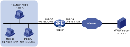
Procedure
# Specify IP addresses for the interfaces on the router. (Details not shown.)
# Configure address group 0, and add an address range from 202.38.1.2 to 202.38.1.3 to the group.
<Router> system-view
[Router] nat address-group 0
[Router-address-group-0] address 202.38.1.2 202.38.1.3
[Router-address-group-0] quit
# Configure ACL 2000 to identify packets from subnet 192.168.1.0/24.
[Router] acl basic 2000
[Router-acl-ipv4-basic-2000] rule permit source 192.168.1.0 0.0.0.255
[Router-acl-ipv4-basic-2000] quit
# Enable outbound dynamic PAT on interface GigabitEthernet 3/1/2. The source IP addresses of the packets permitted by the ACL rule is translated into the addresses in address group 0.
[Router] interface gigabitethernet 3/1/2
[Router-GigabitEthernet3/1/2] nat outbound 2000 address-group 0
# Specify slot 3 to process NAT traffic.
[Router-GigabitEthernet3/1/2] nat service slot 3
[Router-GigabitEthernet3/1/2] quit
# Configure ACL 2001 to identify traffic to be redirected. In this example, ACL 2001 is the same as ACL 2000 because the traffic redirected to the NAT traffic processing slot are NATed. Configure the two ACLs according to your network.
[Router] acl basic 2001
[Router-acl-ipv4-basic-2001] rule permit source 192.168.1.0 0.0.0.255
[Router-acl-ipv4-basic-2001] quit
# Configure a QoS policy to redirect traffic to slot 3.
[Router] traffic classifier 1
[Router-classifier-1] if-match acl 2001
[Router-classifier-1] quit
[Router] traffic behavior 1
[Router-behavior-1] redirect slot 3
[Router-behavior-1] quit
[Router] qos policy 1
[Router-qospolicy-1] classifier 1 behavior 1
[Router-qospolicy-1] quit
[Router] interface Gigabitethernet 3/1/1
[Router-GigabitEthernet3/1/1] qos apply policy 1 inbound
[Router-GigabitEthernet3/1/1] quit
Verifying the configuration
# Verify that Host A can access the WWW server, while Host B cannot. (Details not shown.)
# Display all NAT configuration and statistics.
[Router] display nat all
NAT address group information:
Totally 1 NAT address groups.
Address group 0:
Port range: 1-65535
Address information:
Start address End address
202.38.1.2 202.38.1.3
NAT outbound information:
Totally 1 NAT outbound rules.
Interface: GigabitEthernet3/1/2
ACL: 2000 Address group: 0 Port-preserved: N
NO-PAT: N Reversible: N
Service card: Slot 3
Config status: Active
NAT logging:
Log enable : Disabled
Flow-begin : Disabled
Flow-end : Disabled
Flow-active : Disabled
Port-block-assign : Disabled
Port-block-withdraw : Disabled
Port-alloc-fail : Enabled
Port-block-alloc-fail : Disabled
Port-usage : Disabled
Port-block-usage : Enabled(40%)
NAT mapping behavior:
Mapping mode : Connection-dependent
NAT ALG:
DNS : Disabled
FTP : Enabled
H323 : Disabled
ICMP-ERROR : Enabled
ILS : Disabled
MGCP : Disabled
NBT : Disabled
PPTP : Disabled
RTSP : Enabled
RSH : Disabled
SCCP : Disabled
SIP : Disabled
SQLNET : Disabled
TFTP : Disabled
XDMCP : Disabled
# Display NAT session information generated when Host A accesses the WWW server.
[Router] display nat session verbose
Initiator:
Source IP/port: 192.168.1.10/52992
Destination IP/port: 200.1.1.10/2048
DS-Lite tunnel peer: -
VPN instance/VLAN ID/VLL ID: -/-/-
Protocol: ICMP(1)
Inbound interface: GigabitEthernet3/1/1
Responder:
Source IP/port: 200.1.1.10/4
Destination IP/port: 202.38.1.3/0
DS-Lite tunnel peer: -
VPN instance/VLAN ID/VLL ID: -/-/-
Protocol: ICMP(1)
Inbound interface: GigabitEthernet3/1/2
State: ICMP_REPLY
Application: INVALID
Role: -
Failover group ID: -
Start time: 2012-08-15 14:53:29 TTL: 12s
Initiator->Responder: 1 packets 84 bytes
Responder->Initiator: 1 packets 84 bytes
Total sessions found: 1
Example: Configuring static NAT within a VPN instance
Network configuration
As shown in Figure 20, Host A and Host B are in the same VPN instance. Configure static NAT to allow the hosts to communicate with each other.
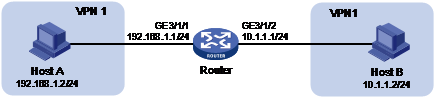
Procedure
# Specify IP addresses for the interfaces on the router. (Details not shown.)
# Configure a one-to-one static NAT mapping between address 192.168.1.2 and address 10.1.1.100.
<Router> system-view
[Router] nat static outbound 192.168.1.2 vpn-instance vpn1 10.1.1.100 vpn-instance vpn1
# Enable static NAT on GigabitEthernet 3/1/2.
[Router] interface gigabitethernet 3/1/2
[Router-GigabitEthernet3/1/2] nat static enable
# Specify slot 3 to process NAT traffic.
[Router-GigabitEthernet3/1/2] nat service slot 3
[Router-GigabitEthernet3/1/2] quit
# Configure ACL 2001 to identify traffic to be redirected.
[Router] acl basic 2001
[Router-acl-ipv4-basic-2001] rule permit source 192.168.1.0 0.0.0.255
[Router-acl-ipv4-basic-2001] quit
# Configure a QoS policy to redirect traffic to slot 3.
[Router] traffic classifier 1
[Router-classifier-1] if-match acl 2001
[Router-classifier-1] quit
[Router] traffic behavior 1
[Router-behavior-1] redirect slot 3
[Router-behavior-1] quit
[Router] qos policy 1
[Router-qospolicy-1] classifier 1 behavior 1
[Router-qospolicy-1] quit
[Router] interface Gigabitethernet 3/1/1
[Router-GigabitEthernet3/1/1] qos apply policy 1 inbound
[Router-GigabitEthernet3/1/1] quit
Verifying the configuration
# Verify that Host A can communicate with Host B. (Details not shown.)
# Display static NAT configuration.
[Router] display nat static
Static NAT mappings:
Totally 1 outbound static NAT mappings.
IP-to-IP:
Local IP : 192.168.1.2
Global IP : 10.1.1.100
Local VPN : vpn1
Global VPN : vpn1
Interfaces enabled with static NAT:
Totally 1 interfaces enabled with static NAT.
Interface: GigabitEthernet3/1/2
Service card : Slot 3
Config status: Active
# Display NAT session information.
[Router] display nat session verbose
Initiator:
Source IP/port: 192.168.1.2/42496
Destination IP/port: 10.1.1.2/2048
DS-Lite tunnel peer: -
VPN instance/VLAN ID/VLL ID: vpn1/-/-
Protocol: ICMP(1)
Inbound interface: GigabitEthernet3/1/1
Responder:
Source IP/port: 10.1.1.2/42496
Destination IP/port: 10.1.1.100/0
DS-Lite tunnel peer: -
VPN instance/VLAN ID/VLL ID: vpn1/-/-
Protocol: ICMP(1)
Inbound interface: GigabitEthernet3/1/2
State: ICMP_REPLY
Application: INVALID
Role: -
Failover group ID: -
Start time: 2012-08-16 09:30:49 TTL: 27s
Initiator->Responder: 5 packets 420 bytes
Responder->Initiator: 5 packets 420 bytes
Total sessions found: 1
Example: Configuring NAT Server for external-to-internal access
Network configuration
As shown in Figure 21, two Web servers, one FTP server and one SMTP server are in the internal network to provide services for external users. The internal network address is 10.110.0.0/16. The company has three public IP addresses from 202.38.1.1/24 to 202.38.1.3/24.
Configure the NAT Server feature to allow the external user to access the internal servers with public address 202.38.1.1/24.
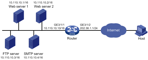
Procedure
# Specify IP addresses for the interfaces on the router. (Details not shown.)
# Enter interface view of GigabitEthernet 3/1/2.
<Router> system-view
[Router] interface gigabitethernet 3/1/2
# Configure NAT Server to allow external users to access the FTP server by using the address 202.38.1.1 and port 21.
[Router-GigabitEthernet3/1/2] nat server protocol tcp global 202.38.1.1 21 inside 10.110.10.3 ftp
# Configure NAT Server to allow external users to access the Web server 1 by using the address 202.38.1.1 and port 80.
[Router-GigabitEthernet3/1/2] nat server protocol tcp global 202.38.1.1 80 inside 10.110.10.1 http
# Configure NAT Server to allow external users to access the Web server 2 by using the address 202.38.1.1 and port 8080.
[Router-GigabitEthernet3/1/2] nat server protocol tcp global 202.38.1.1 8080 inside 10.110.10.2 http
# Configure NAT Server to allow external users to access the SMTP server by using the address 202.38.1.1 and port number defined by SMTP.
[Router-GigabitEthernet3/1/2] nat server protocol tcp global 202.38.1.1 smtp inside 10.110.10.4 smtp
# Specify slot 3 to process NAT traffic.
[Router-GigabitEthernet3/1/2] nat service slot 3
[Router-GigabitEthernet3/1/2] quit
# Configure ACL 2001 to identify traffic to be redirected.
[Router] acl basic 2001
[Router-acl-ipv4-basic-2001] rule permit source 10.110.10.0 0.0.0.255
[Router-acl-ipv4-basic-2001] quit
# Configure a QoS policy to redirect traffic to slot 3.
[Router] traffic classifier 1
[Router-classifier-1] if-match acl 2001
[Router-classifier-1] quit
[Router] traffic behavior 1
[Router-behavior-1] redirect slot 3
[Router-behavior-1] quit
[Router] qos policy 1
[Router-qospolicy-1] classifier 1 behavior 1
[Router-qospolicy-1] quit
[Router] interface Gigabitethernet 3/1/1
[Router-GigabitEthernet3/1/1] qos apply policy 1 inbound
Verifying the configuration
# Verify that the host on the external network can access the internal servers by using the public addresses. (Details not shown.)
# Display all NAT configuration and statistics.
[Router] display nat all
NAT internal server information:
Totally 4 internal servers.
Interface: GigabitEthernet3/1/2
Protocol: 6(TCP)
Global IP/port: 202.38.1.1/21
Local IP/port : 10.110.10.3/21
Service card : Slot 3
Config status : Active
Interface: GigabitEthernet3/1/2
Protocol: 6(TCP)
Global IP/port: 202.38.1.1/25
Local IP/port : 10.110.10.4/25
Service card : Slot 3
Config status : Active
Interface: GigabitEthernet3/1/2
Protocol: 6(TCP)
Global IP/port: 202.38.1.1/80
Local IP/port : 10.110.10.1/80
Service card : Slot 3
Config status : Active
Interface: GigabitEthernet3/1/2
Protocol: 6(TCP)
Global IP/port: 202.38.1.1/8080
Local IP/port : 10.110.10.2/80
Service card : Slot 3
Config status : Active
NAT logging:
Log enable : Disabled
Flow-begin : Disabled
Flow-end : Disabled
Flow-active : Disabled
Port-block-assign : Disabled
Port-block-withdraw : Disabled
Port-alloc-fail : Enabled
Port-block-alloc-fail : Disabled
Port-usage : Disabled
Port-block-usage : Enabled(40%)
NAT mapping behavior:
Mapping mode : Connection-dependent
NAT ALG:
DNS : Disabled
FTP : Enabled
H323 : Disabled
ICMP-ERROR : Enabled
ILS : Disabled
MGCP : Disabled
NBT : Disabled
PPTP : Disabled
RTSP : Enabled
RSH : Disabled
SCCP : Disabled
SIP : Disabled
SQLNET : Disabled
TFTP : Disabled
XDMCP : Disabled
# Display NAT session information generated when Host accesses the FTP server.
[Router] display nat session verbose
Initiator:
Source IP/port: 202.38.1.10/1694
Destination IP/port: 202.38.1.1/21
DS-Lite tunnel peer: -
VPN instance/VLAN ID/VLL ID: -/-/-
Protocol: TCP(6)
Inbound interface: GigabitEthernet3/1/2
Responder:
Source IP/port: 10.110.10.3/21
Destination IP/port: 202.38.1.10/1694
DS-Lite tunnel peer: -
VPN instance/VLAN ID/VLL ID: -/-/-
Protocol: TCP(6)
Inbound interface: GigabitEthernet3/1/1
State: TCP_ESTABLISHED
Application: FTP
Role: -
Failover group ID: -
Start time: 2012-08-15 14:53:29 TTL: 3597s
Initiator->Responder: 7 packets 308 bytes
Responder->Initiator: 5 packets 312 bytes
Total sessions found: 1
Example: Configuring NAT Server for external-to-internal access through domain name
Network configuration
As shown in Figure 22, Web server at 10.110.10.2/24 in the internal network provides services for external users. A DNS server at 10.110.10.3/24 is used to resolve the domain name of the Web server. The company has two public IP addresses: 202.38.1.2 and 202.38.1.3.
Configure NAT Server to allow external users to access the internal Web server by using the domain name.
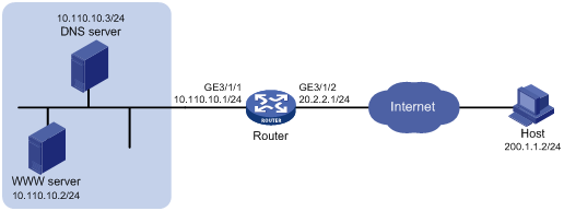
Analysis
To meet the network configuration requirements, you must perform the following tasks:
· Configure NAT Server to map the private IP address and port of the DNS server to a public address and port. NAT Server allows the external host to access the internal DNS server for domain name resolution.
· Enable ALG for DNS and configure outbound dynamic NAT to translate the private IP address of the Web server in the payload of the DNS response packet into a public IP address.
Procedure
# Specify IP addresses for the interfaces on the router. (Details not shown.)
# Enable NAT ALG for DNS.
<Router> system-view
[Router] nat alg dns
# Configure ACL 2000 to identify packets from 10.110.10.2.
[Router] acl basic 2000
[Router-acl-ipv4-basic-2000] rule permit source 10.110.10.2 0
[Router-acl-ipv4-basic-2000] quit
# Create address group 1.
[Router] nat address-group 1
# Add address 202.38.1.3 to the group.
[Router-address-group-1] address 202.38.1.3 202.38.1.3
[Router-address-group-1] quit
# Configure NAT Server on interface GigabitEthernet 3/1/2 to map the address 202.38.1.1 to 10.110.10.3. External users can access the internal DNS server.
[Router] interface gigabitethernet 3/1/2
[Router-GigabitEthernet3/1/2] nat server protocol udp global 202.38.1.2 inside 10.110.10.3 dns
# Enable outbound NO-PAT on interface GigabitEthernet 3/1/2. Use the address in address group 1 to translate the private address in DNS response payload, and allow reversible NAT.
[Router-GigabitEthernet3/1/2] nat outbound 2000 address-group 1 no-pat reversible
# Specify slot 3 to process NAT traffic.
[Router-GigabitEthernet3/1/2] nat service slot 3
[Router-GigabitEthernet3/1/2] quit
# Configure ACL 2001 to identify traffic to be redirected.
[Router] acl basic 2001
[Router-acl-ipv4-basic-2001] rule permit source 10.110.10.0 0.0.0.255
[Router-acl-ipv4-basic-2001] quit
# Configure a QoS policy to redirect traffic to slot 3.
[Router] traffic classifier 1
[Router-classifier-1] if-match acl 2001
[Router-classifier-1] quit
[Router] traffic behavior 1
[Router-behavior-1] redirect slot 3
[Router-behavior-1] quit
[Router] qos policy 1
[Router-qospolicy-1] classifier 1 behavior 1
[Router-qospolicy-1] quit
[Router] interface Gigabitethernet 3/1/1
[Router-GigabitEthernet3/1/1] qos apply policy 1 inbound
Verifying the configuration
# Verify that the host on the external network can access the internal Web server by using the server's domain name. (Details not shown.)
# Display all NAT configuration and statistics.
[Router] display nat all
NAT address group information:
Totally 1 NAT address groups.
Address group 1:
Port range: 1-65535
Address information:
Start address End address
202.38.1.3 202.38.1.3
NAT outbound information:
Totally 1 NAT outbound rules.
Interface: GigabitEthernet3/1/2
ACL: 2000 Address group: 1 Port-preserved: N
NO-PAT: Y Reversible: Y
Service card: Slot 3
Config status: Active
NAT internal server information:
Totally 1 internal servers.
Interface: GigabitEthernet3/1/2
Protocol: 17(UDP)
Global IP/port: 202.38.1.2/53
Local IP/port : 10.110.10.3/53
Service card : Slot 3
Config status : Active
NAT logging:
Log enable : Disabled
Flow-begin : Disabled
Flow-end : Disabled
Flow-active : Disabled
Port-block-assign : Disabled
Port-block-withdraw : Disabled
Port-alloc-fail : Enabled
Port-block-alloc-fail : Disabled
Port-usage : Disabled
Port-block-usage : Enabled(40%)
NAT mapping behavior:
Mapping mode : Connection-dependent
NAT ALG:
DNS : Enabled
FTP : Enabled
H323 : Disabled
ICMP-ERROR : Enabled
ILS : Disabled
MGCP : Disabled
NBT : Disabled
PPTP : Disabled
RTSP : Enabled
RSH : Disabled
SCCP : Disabled
SIP : Disabled
SQLNET : Disabled
TFTP : Disabled
XDMCP : Disabled
# Display NAT session information generated when Host accesses Web server.
[Router] display nat session verbose
Initiator:
Source IP/port: 200.1.1.2/1694
Destination IP/port: 202.38.1.3/8080
DS-Lite tunnel peer: -
VPN instance/VLAN ID/VLL ID: -/-/-
Protocol: TCP(6)
Inbound interface: GigabitEthernet3/1/2
Responder:
Source IP/port: 10.110.10.2/8080
Destination IP/port: 202.1.1.2/1694
DS-Lite tunnel peer: -
VPN instance/VLAN ID/VLL ID: -/-/-
Protocol: TCP(6)
Inbound interface: GigabitEthernet3/1/1
State: TCP_ESTABLISHED
Application: HTTP
Role: -
Failover group ID: -
Start time: 2012-08-15 14:53:29 TTL: 3597s
Initiator->Responder: 7 packets 308 bytes
Responder->Initiator: 5 packets 312 bytes
Total sessions found: 1
Example: Configuring NAT hairpin in C/S mode
Network configuration
As shown in Figure 23, the internal FTP server at 192.168.1.4/24 provides services for internal and external users. The private network uses two public IP addresses 202.38.1.1 and 202.38.1.2.
Configure NAT hairpin in C/S mode to allow external and internal users to access the internal FTP server by using public IP address 202.38.1.2.
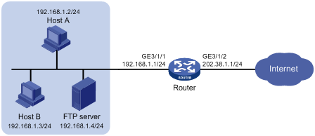
Requirements analysis
To allow external hosts to access the internal FTP server by using a public IP address, configure NAT Server on the interface connected to the external network.
To allow internal hosts to access the internal FTP server by using a public IP address, perform the following tasks:
· Enable NAT hairpin on the interface connected to the internal network.
· Configure outbound NAT on the interface where NAT Server is configured. The destination address is translated by matching the NAT Server. The source address is translated by matching the outbound NAT.
Procedure
# Specify IP addresses for the interfaces on the router. (Details not shown.)
# Configure ACL 2000, and create a rule to permit packets only from subnet 192.168.1.0/24 to be translated.
<Router> system-view
[Router] acl basic 2000
[Router-acl-ipv4-basic-2000] rule permit source 192.168.1.0 0.0.0.255
[Router-acl-ipv4-basic-2000] quit
# Configure NAT Server on interface GigabitEthernet 3/1/2 to map the IP address of the FTP server to a public address, allowing external users to access the internal FTP server.
[Router] interface gigabitethernet 3/1/2
[Router-GigabitEthernet3/1/2] nat server protocol tcp global 202.38.1.2 inside 192.168.1.4 ftp
# Enable outbound NAT with Easy IP on interface GigabitEthernet 3/1/2 so that NAT translates the source addresses of the packets from internal hosts into the IP address of interface GigabitEthernet 3/1/2.
[Router-GigabitEthernet3/1/2] nat outbound 2000
# Specify slot 3 to process NAT traffic for GigabitEthernet 3/1/2.
[Router-GigabitEthernet3/1/2] nat service slot 3
[Router-GigabitEthernet3/1/2] quit
# Enable NAT hairpin on interface GigabitEthernet 3/1/1.
[Router] interface gigabitethernet 3/1/1
[Router-GigabitEthernet3/1/1] nat hairpin enable
# Specify slot 3 to process NAT traffic for GigabitEthernet 3/1/1.
[Router-GigabitEthernet3/1/1] nat service slot 3
[Router-GigabitEthernet3/1/1] quit
# Configure ACL 2001 to identify traffic to be redirected. In this example, ACL 2001 is the same as ACL 2000 because the traffic redirected to the NAT traffic processing slot are NATed. Configure the two ACLs according to your network.
[Router] acl basic 2001
[Router-acl-ipv4-basic-2001] rule permit source 192.168.1.0 0.0.0.255
[Router-acl-ipv4-basic-2001] quit
# Configure a QoS policy to redirect traffic to slot 3.
[Router] traffic classifier 1
[Router-classifier-1] if-match acl 2001
[Router-classifier-1] quit
[Router] traffic behavior 1
[Router-behavior-1] redirect slot 3
[Router-behavior-1] quit
[Router] qos policy 1
[Router-qospolicy-1] classifier 1 behavior 1
[Router-qospolicy-1] quit
[Router] interface Gigabitethernet 3/1/1
[Router-GigabitEthernet3/1/1] qos apply policy 1 inbound
Verifying the configuration
# Verify that both internal and external hosts can access the internal FTP server through the public address. (Details not shown.)
# Display all NAT configuration and statistics.
[Router]display nat all
NAT outbound information:
Totally 1 NAT outbound rules.
Interface: GigabitEthernet3/1/2
ACL: 2000 Address group: --- Port-preserved: N
NO-PAT: N Reversible: N
Service card: Slot 3
Config status: Active
NAT internal server information:
Totally 1 internal servers.
Interface: GigabitEthernet3/1/2
Protocol: 6(TCP)
Global IP/port: 202.38.1.2/21
Local IP/port : 192.168.1.4/21
Service card : Slot 3
Config status : Active
NAT logging:
Log enable : Disabled
Flow-begin : Disabled
Flow-end : Disabled
Flow-active : Disabled
Port-block-assign : Disabled
Port-block-withdraw : Disabled
Port-alloc-fail : Enabled
Port-block-alloc-fail : Disabled
Port-usage : Disabled
Port-block-usage : Enabled(40%)
NAT hairpinning:
Totally 1 interfaces enabled with NAT hairpinning.
Interface: GigabitEthernet3/1/1
Service card : Slot 3
Config status: Active
NAT mapping behavior:
Mapping mode : Connection-dependent
NAT ALG:
DNS : Disabled
FTP : Enabled
H323 : Disabled
ICMP-ERROR : Enabled
ILS : Disabled
MGCP : Disabled
NBT : Disabled
PPTP : Disabled
RTSP : Enabled
RSH : Disabled
SCCP : Disabled
SIP : Disabled
SQLNET : Disabled
TFTP : Disabled
XDMCP : Disabled
# Display NAT session information generated when Host A accesses the FTP server.
[Router] display nat session verbose
Initiator:
Source IP/port: 192.168.1.2/1694
Destination IP/port: 202.38.1.2/21
DS-Lite tunnel peer: -
VPN instance/VLAN ID/VLL ID: -/-/-
Protocol: TCP(6)
Inbound interface: GigabitEthernet3/1/1
Responder:
Source IP/port: 192.168.1.4/21
Destination IP/port: 202.38.1.1/1025
DS-Lite tunnel peer: -
VPN instance/VLAN ID/VLL ID: -/-/-
Protocol: TCP(6)
Inbound interface: GigabitEthernet3/1/1
State: TCP_ESTABLISHED
Application: FTP
Role: -
Failover group ID: -
Start time: 2012-08-15 14:53:29 TTL: 3597s
Initiator->Responder: 7 packets 308 bytes
Responder->Initiator: 5 packets 312 bytes
Example: Configuring load sharing NAT Server
Network configuration
As shown in Figure 24, three FTP servers are in the intranet to provide FTP services for external users. Configure NAT so that these external users use the address 202.38.1.1/16 to access the servers and the three FTP servers implement load sharing.
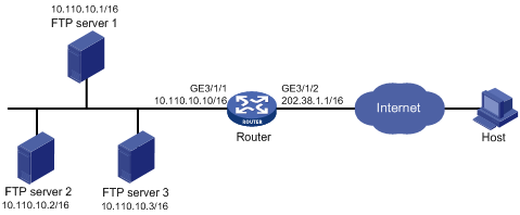
Procedure
# Specify IP addresses for the interfaces on the router. (Details not shown.)
# Create NAT Server group 0, and add members to the group.
<Router> system-view
[Router] nat server-group 0
[Router-nat-server-group-0] inside ip 10.110.10.1 port 21
[Router-nat-server-group-0] inside ip 10.110.10.2 port 21
[Router-nat-server-group-0] inside ip 10.110.10.3 port 21
[Router-nat-server-group-0] quit
# Associate NAT Server group 0 with GigabitEthernet 3/1/2 so that servers in the server group can provide FTP services.
[Router] interface gigabitethernet 3/1/2
[Router-GigabitEthernet3/1/2] nat server protocol tcp global 202.38.1.1 ftp inside server-group 0
# Specify slot 3 to process NAT traffic.
[Router-GigabitEthernet3/1/2] nat service slot 3
[Router-GigabitEthernet3/1/2] quit
# Configure ACL 2001 to identify traffic to be redirected.
[Router] acl basic 2001
[Router-acl-ipv4-basic-2001] rule permit source 10.110.10.0 0.0.0.255
[Router-acl-ipv4-basic-2001] quit
# Configure a QoS policy to redirect traffic to slot 3.
[Router] traffic classifier 1
[Router-classifier-1] if-match acl 2001
[Router-classifier-1] quit
[Router] traffic behavior 1
[Router-behavior-1] redirect slot 3
[Router-behavior-1] quit
[Router] qos policy 1
[Router-qospolicy-1] classifier 1 behavior 1
[Router-qospolicy-1] quit
[Router] interface Gigabitethernet 3/1/1
[Router-GigabitEthernet3/1/1] qos apply policy 1 inbound
[Router-GigabitEthernet3/1/1] quit
Verifying the configuration
# Verify that external hosts can access the internal FTP server group. (Details not shown.)
# Display all NAT configuration and statistics.
[Router] display nat all
NAT server group information:
Totally 1 NAT server groups.
Group Number Inside IP Port Weight
0 10.110.10.1 21 100
10.110.10.2 21 100
10.110.10.3 21 100
NAT internal server information:
Totally 1 internal servers.
Interface: GigabitEthernet3/1/2
Protocol: 6(TCP)
Global IP/port: 202.38.1.1/21
Local IP/port : server group 0
10.110.10.1/21 (Connections: 1)
10.110.10.2/21 (Connections: 2)
10.110.10.3/21 (Connections: 2)
Service card : Slot 3
Config status : Active
NAT logging:
Log enable : Disabled
Flow-begin : Disabled
Flow-end : Disabled
Flow-active : Disabled
Port-block-assign : Disabled
Port-block-withdraw : Disabled
Port-alloc-fail : Enabled
Port-block-alloc-fail : Disabled
Port-usage : Disabled
Port-block-usage : Enabled(40%)
NAT mapping behavior:
Mapping mode : Connection-dependent
NAT ALG:
DNS : Disabled
FTP : Enabled
H323 : Disabled
ICMP-ERROR : Enabled
ILS : Disabled
MGCP : Disabled
NBT : Disabled
PPTP : Disabled
RTSP : Enabled
RSH : Disabled
SCCP : Disabled
SIP : Disabled
SQLNET : Disabled
TFTP : Disabled
XDMCP : Disabled
# Display NAT session information generated when external hosts access an internal FTP server.
[Router] display nat session verbose
Initiator:
Source IP/port: 202.38.1.25/53957
Destination IP/port: 202.38.1.1/21
DS-Lite tunnel peer: -
VPN instance/VLAN ID/VLL ID: -/-/-
Protocol: TCP(6)
Inbound interface: GigabitEthernet3/1/2
Responder:
Source IP/port: 10.110.10.3/21
Destination IP/port: 202.38.1.25/53957
DS-Lite tunnel peer: -
VPN instance/VLAN ID/VLL ID: -/-/-
Protocol: TCP(6)
Inbound interface: GigabitEthernet3/1/1
State: TCP_ESTABLISHED
Application: FTP
Role: -
Failover group ID: -
Start time: 2012-08-16 11:06:07 TTL: 26s
Initiator->Responder: 1 packets 60 bytes
Responder->Initiator: 2 packets 120 bytes
Total sessions found: 1
Example: Configuring NAT DNS mapping
Network configuration
As shown in Figure 25, the internal Web server at 10.110.10.1/16 and FTP server at 10.110.10.2/16 provide services for external user. The company has three public addresses 202.38.1.1 through 202.38.1.3. The DNS server at 202.38.1.4 is on the external network.
Configure NAT so that:
· The public IP address 202.38.1.2 is used by external users to access the Web and FTP servers.
· External users can use the public address or domain name of internal servers to access them.
· Internal users can access the internal servers by using their domain names.
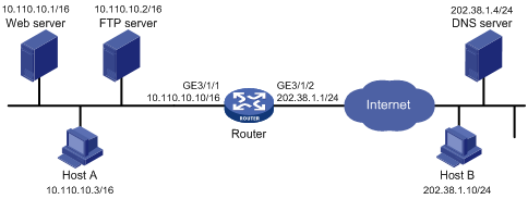
Requirements analysis
To meet the network requirements, perform the following tasks:
· Configure NAT Server by mapping the public IP addresses and port numbers of the internal servers to a public address and port numbers so that external users can access the internal servers.
· Configure NAT DNS mapping and ALG so that the public IP address of the internal server in the payload of the DNS response packet can be translated to the private IP address.
Procedure
# Specify IP addresses for the interfaces on the router. (Details not shown.)
# Enable NAT ALG for DNS.
<Router> system-view
[Router] nat alg dns
# Enter interface view of GigabitEthernet 3/1/2.
[Router] interface gigabitethernet 3/1/2
# Configure NAT Server to allow external hosts to access the internal Web server by using the address 202.38.1.2.
[Router-GigabitEthernet3/1/2] nat server protocol tcp global 202.38.1.2 inside 10.110.10.1 http
# Configure NAT Server to allow external hosts to access the internal FTP server by using the address 202.38.1.2.
[Router-GigabitEthernet3/1/2] nat server protocol tcp global 202.38.1.2 inside 10.110.10.2 ftp
# Enable outbound NAT with Easy IP on interface GigabitEthernet 3/1/2.
[Router-GigabitEthernet3/1/2] nat outbound
# Specify slot 3 to process NAT traffic.
[Router-GigabitEthernet3/1/2] nat service slot 3
[Router-GigabitEthernet3/1/2] quit
# Configure two NAT DNS mapping entries by mapping the domain name www.server.com of the Web server to 202.38.1.2, and ftp.server.com of the FTP server to 202.38.1.2.
[Router] nat dns-map domain www.server.com protocol tcp ip 202.38.1.2 port http
[Router] nat dns-map domain ftp.server.com protocol tcp ip 202.38.1.2 port ftp
[Router] quit
# Configure ACL 2001 to identify traffic to be redirected.
[Router] acl basic 2001
[Router-acl-ipv4-basic-2001] rule permit source 10.110.10.0 0.0.0.255
[Router-acl-ipv4-basic-2001] quit
# Configure a QoS policy to redirect traffic to slot 3.
[Router] traffic classifier 1
[Router-classifier-1] if-match acl 2001
[Router-classifier-1] quit
[Router] traffic behavior 1
[Router-behavior-1] redirect slot 3
[Router-behavior-1] quit
[Router] qos policy 1
[Router-qospolicy-1] classifier 1 behavior 1
[Router-qospolicy-1] quit
[Router] interface Gigabitethernet 3/1/1
[Router-GigabitEthernet3/1/1] qos apply policy 1 inbound
[Router-GigabitEthernet3/1/1] quit
Verifying the configuration
# Verify that both internal and external hosts can access the internal servers by using domain names. (Details not shown.)
# Display all NAT configuration and statistics.
[Router] display nat all
NAT outbound information:
Totally 1 NAT outbound rules.
Interface: GigabitEthernet3/1/2
ACL: --- Address group: --- Port-preserved: N
NO-PAT: N Reversible: N
Service card: Slot 3
Config status: Active
NAT internal server information:
Totally 2 internal servers.
Interface: GigabitEthernet3/1/2
Protocol: 6(TCP)
Global IP/port: 202.38.1.2/21
Local IP/port : 10.110.10.2/21
Service card : Slot 3
Config status : Active
Interface: GigabitEthernet3/1/2
Protocol: 6(TCP)
Global IP/port: 202.38.1.2/80
Local IP/port : 10.110.10.1/80
Service card : Slot 3
Config status : Active
NAT DNS mapping information:
Totally 2 NAT DNS mappings.
Domain name: ftp.server.com
Global IP : 202.38.1.2
Global port: 21
Protocol : TCP(6)
Config status: Active
Domain name: www.server.com
Global IP : 202.38.1.2
Global port: 80
Protocol : TCP(6)
Config status: Active
NAT logging:
Log enable : Disabled
Flow-begin : Disabled
Flow-end : Disabled
Flow-active : Disabled
Port-block-assign : Disabled
Port-block-withdraw : Disabled
Port-alloc-fail : Enabled
Port-block-alloc-fail : Disabled
Port-usage : Disabled
Port-block-usage : Enabled(40%)
NAT mapping behavior:
Mapping mode : Connection-dependent
NAT ALG:
DNS : Enabled
FTP : Enabled
H323 : Disabled
ICMP-ERROR : Enabled
ILS : Disabled
MGCP : Disabled
NBT : Disabled
PPTP : Disabled
RTSP : Enabled
RSH : Disabled
SCCP : Disabled
SIP : Disabled
SQLNET : Disabled
TFTP : Disabled
XDMCP : Disabled
Example: Configuring NAT log export to the information center
Network configuration
As shown in Figure 26, configure NAT on the device for the internal host to access the Internet. Configure NAT logging on the device and configure the device to export the NAT logs to the information center. The NAT logs in the information center are used for monitoring the internal host.

Procedure
# Assign IP addresses to interfaces on the device and make sure the device and the host can reach each other. (Details not shown.)
# Specify the information center as the destination for flow log export.
<Device> system-view
[Device] userlog flow syslog
# Enable NAT logging.
[Device] nat log enable
# Enable logging for NAT session establishment events.
[Device] nat log flow-begin
# Enable logging for NAT session removal events.
[Device] nat log flow-end
# Enable logging for active NAT flows and set the logging interval to 10 minutes.
[Device] nat log flow-active 10
[Device] quit
Verifying the configuration
# Display the internal host's access records in the log buffer.
<Device> dir
Directory of cf:/
38 -rw- 141 Aug 07 2015 17:54:43 ifindex.dat
39 drw- - Aug 18 2014 17:51:38 license
40 drw- - May 20 2015 14:36:20 logfile
249852 KB total (232072 KB free)
File system type of cf: FAT32
<Device> cd logfile
<Device> dir
<Device> more logfile.log
…
%Aug 10 20:06:30:182 2015 Device NAT/6/NAT_FLOW: Protocol(1001)=ICMP;SrcIPAd
dr(1003)=10.110.10.8;SrcPort(1004)=259;NatSrcIPAddr(1005)=202.38.1.100;NatSrcPor
t(1006)=0;DstIPAddr(1007)=202.38.1.2;DstPort(1008)=2048;NatDstIPAddr(1009)=202.3
8.1.2;NatDstPort(1010)=259;InitPktCount(1044)=0;InitByteCount(1046)=0;RplyPktCou
nt(1045)=0;RplyByteCount(1047)=0;RcvVPNInstance(1042)=;SndVPNInstance(1043)=;Rcv
DSLiteTunnelPeer(1040)=;SndDSLiteTunnelPeer(1041)=;BeginTime_e(1013)=08102015200
630; EndTime_e(1014)=08102015200700;Event(1048)=(8)Session created;
…
Table 2 Command output
|
Field |
Description |
|
Protocol(1001)=ICMP |
Protocol type. |
|
SrcIPAddr(1003)=10.110.10.8 |
Source IP address before NAT. |
|
SrcPort(1004)=259 |
Source TCP or UDP port before NAT. |
|
NatSrcIPAddr(1005)=202.38.1.100 |
Source IP address after NAT. |
|
NatSrcPort(1006)=0 |
Source TCP or UDP port after NAT. |
|
DstIPAddr(1007)=202.38.1.2 |
Destination IP address before NAT. |
|
DstPort(1008)=2048 |
Destination TCP or UDP port before NAT. |
|
NatDstIPAddr(1009)=202.38.1.2 |
Destination IP address after NAT. |
|
NatDstPort(1010)=259 |
Destination TCP or UDP port after NAT. |
|
BeginTime_e(1013)=08102015200630 |
Start time of the flow, in the MMDDYYYYHHMMSS format. |
|
EndTime_e(1014)=08102015200700 |
End time of the flow, in the MMDDYYYYHHMMSS format. |
Example: Configuring NAT log export to the log server
Network configuration
As shown in Figure 27, configure the device to export the NAT logs to the log server. The NAT logs in the log server are used for monitoring the internal user.

Procedure
# Assign IP addresses to interfaces on the device. (Details not shown.)
# Make sure the device and the user can reach each other. (Details not shown.)
# Make sure the device and the log server can reach each other. (Details not shown.)
# Enable NAT logging.
<Device> system-view
[Device] nat log enable
# Enable logging for NAT session establishment events.
[Device] nat log flow-begin
# Enable logging for NAT session removal events.
[Device] nat log flow-end
# Enable logging for active NAT flows and set the logging interval to 10 minutes.
[Device] nat log flow-active 10
# Set the flow log version to 3.0.
[Device] userlog flow export version 3
# Export flow log entries to port 2000 on the log host at 1.2.3.6.
[Device] userlog flow export host 1.2.3.6 port 2000
# Specify 2.2.2.2 as the source IP address for flow log packets.
[Device] userlog flow export source-ip 2.2.2.2
[Device] quit
Verifying the configuration
# Display the flow log configuration and statistics.
<Device> display userlog export
Flow:
Export flow log as UDP Packet.
Version: 3.0
Source ipv4 address: 2.2.2.2
Source ipv6 address:
Log load balance function: Disabled
Local time stamp: Disabled
Number of log hosts: 1
Log host 1:
Host/Port: 1.2.3.6/2000
Total logs/UDP packets exported: 112/87
NAT configuration examples (using CGN cards for NAT processing)
|
|
NOTE: In the following configuration examples, the nodes assigned the failover group by the bind command are all CGN cards. The slot numbers in the examples are for illustration only. |
Example: Configuring outbound one-to-one static NAT
Network configuration
Configure static NAT to allow the host at 10.110.10.8/24 to access the Internet.
Figure 28 Network diagram
Procedure
# Specify IP addresses for the interfaces on the router. (Details not shown.)
# Specify the card in the specified slot as the primary node in failover group cgn.
<Router> system-view
[Router] failover group cgn id 1
[Router-failover-group-cgn] bind slot 2 primary
[Router-failover-group-cgn] quit
# Configure a one-to-one static NAT mapping between the private address 10.110.10.8 and the public address 202.38.1.100.
[Router] nat static outbound 10.110.10.8 202.38.1.100 failover-group cgn
# Configure ACL 2000 to identify packets from subnet 10.110.10.0/24 to pass through.
[Router] acl basic 2000
[Router-acl-ipv4-basic-2000] rule permit source 10.110.10.0 0.0.0.255
[Router-acl-ipv4-basic-2000] quit
# Configure traffic class cgn and traffic behavior cgn to redirect packets matching ACL 2000 to failover group cgn.
[Router] traffic classifier cgn
[Router-classifier-cgn] if-match acl 2000
[Router-classifier-cgn] quit
[Router] traffic behavior cgn
[Router-behavior-cgn] redirect failover-group cgn
[Router-behavior-cgn] quit
# Configure a QoS policy and associate the traffic class with the traffic behavior.
[Router] qos policy cgn
[Router-qospolicy-cgn] classifier cgn behavior cgn
[Router-qospolicy-cgn] quit
# Apply the QoS policy to the inbound traffic on GigabitEthernet 3/1/1.
[Router] interface gigabitethernet 3/1/1
[Router-GigabitEthernet3/1/1] qos apply policy cgn inbound
[Router-GigabitEthernet3/1/1] quit
# Enable static NAT on GigabitEthernet 3/1/2.
[Router] interface gigabitethernet 3/1/2
[Router-GigabitEthernet3/1/2] nat static enable
[Router-GigabitEthernet3/1/2] quit
# Configure a failover group to process session-based services. Traffic permitted by ACL 2000 are redirected to the primary node of failover group cgn for service processing.
[Router] session service-location acl 2000 failover-group cgn
Verifying the configuration
# Verify that the host at 10.110.10.8/24 can access the server on the Internet. (Details not shown.)
# Display static NAT configuration.
[Router] display nat static
Static NAT mappings:
Totally 1 outbound static NAT mappings.
IP-to-IP:
Local IP : 10.110.10.8
Global IP : 202.38.1.100
Failover group name: cgn
Config status: Active
Interfaces enabled with static NAT:
Totally 1 interfaces enabled with static NAT.
Interface: GigabitEthernet3/1/2
Service card : ---
Config status: Active
# Display NAT session information.
[Router] display nat session slot 2 verbose
Slot 2:
Initiator:
Source IP/port: 10.110.10.8/1024
Destination IP/port: 202.38.1.111/1025
DS-Lite tunnel peer: -
VPN instance/VLAN ID/Inline ID: -/-/-
Protocol: UDP(17)
Inbound interface: GigabitEthernet3/1/1
Responder:
Source IP/port: 202.38.1.111/1025
Destination IP/port: 202.38.1.100/1024
DS-Lite tunnel peer: -
VPN instance/VLAN ID/Inline ID: -/-/-
Protocol: UDP(17)
Inbound interface: GigabitEthernet3/1/2
State: UDP_READY
Application: OTHER
Role: Master
Failover group ID: 1
Start time: 2015-05-29 18:49:37
Initiator->Responder: 0 packets 0 bytes
Responder->Initiator: 0 packets 0 bytes
Total sessions found: 1
Example: Configuring outbound dynamic NAT (non-overlapping addresses)
Network configuration
As shown in Figure 29, a company has a private address 192.168.0.0/16 and two public IP addresses 202.38.1.2 and 202.38.1.3. Configure outbound dynamic NAT to allow only internal users on subnet 192.168.1.0/24 to access the Internet.

Procedure
# Specify IP addresses for the interfaces on the router. (Details not shown.)
# Specify the card in the specified slot as the primary node in failover group cgn.
<Router> system-view
[Router] failover group cgn id 1
[Router-failover-group-cgn] bind slot 2 primary
[Router-failover-group-cgn] quit
# Configure address group 0, add an address range from 202.38.1.2 to 202.38.1.3, and specify failover group cgn for address group 0.
[Router] nat address-group 0
[Router-address-group-0] address 202.38.1.2 202.38.1.3
[Router-address-group-0] failover-group cgn
[Router-address-group-0] quit
# Configure ACL 2000 to identify packets from subnet 192.168.1.0/24.
[Router] acl basic 2000
[Router-acl-ipv4-basic-2000] rule permit source 192.168.1.0 0.0.0.255
[Router-acl-ipv4-basic-2000] quit
# Configure traffic class cgn and traffic behavior cgn to redirect packets matching ACL 2000 to failover group cgn.
[Router] traffic classifier cgn
[Router-classifier-cgn] if-match acl 2000
[Router-classifier-cgn] quit
[Router] traffic behavior cgn
[Router-behavior-cgn] redirect failover-group cgn
[Router-behavior-cgn] quit
# Configure a QoS policy and associate the traffic class with the traffic behavior.
[Router] qos policy cgn
[Router-qospolicy-cgn] classifier cgn behavior cgn
[Router-qospolicy-cgn] quit
# Apply the QoS policy to the outbound traffic on GigabitEthernet 3/1/1.
[Router] interface gigabitethernet 3/1/1
[Router-GigabitEthernet3/1/1] qos apply policy cgn inbound
[Router-GigabitEthernet3/1/1] quit
# Enable outbound dynamic PAT on GigabitEthernet 3/1/2. The source IP addresses of the packets permitted by ACL 2000 are translated into the addresses in address group 0.
[Router] interface gigabitethernet 3/1/2
[Router-GigabitEthernet3/1/2] nat outbound 2000 address-group 0
[Router-GigabitEthernet3/1/2] quit
# Configure a failover group to process session-based services. Traffic permitted by ACL 2000 are redirected to the primary node of failover group cgn for service processing.
[Router] session service-location acl 2000 failover-group cgn
Verifying the configuration
# Verify that Host A can access the WWW server and Host B cannot. (Details not shown.)
# Display all NAT configuration information.
[Router] display nat all
NAT address group information:
Totally 1 NAT address groups.
Address group 0:
Port range: 1-65535
Failover group name: cgn
Address information:
Start address End address
202.38.1.2 202.38.1.3
NAT outbound information:
Totally 1 NAT outbound rules.
Interface: GigabitEthernet3/1/2
ACL: 2000 Address group: 0 Port-preserved: N
NO-PAT: N Reversible: N
Config status: Active
NAT logging:
Log enable : Disabled
Flow-begin : Disabled
Flow-end : Disabled
Flow-active : Disabled
Port-block-assign : Disabled
Port-block-withdraw : Disabled
Port-alloc-fail : Enabled
Port-block-alloc-fail : Disabled
Port-usage : Disabled
Port-block-usage : Enabled(40%)
NAT mapping behavior:
Mapping mode : Connection-dependent
NAT ALG:
DNS : Disabled
FTP : Enabled
H323 : Disabled
ICMP-ERROR : Enabled
ILS : Disabled
MGCP : Disabled
NBT : Disabled
PPTP : Disabled
RTSP : Enabled
RSH : Disabled
SCCP : Disabled
SIP : Disabled
SQLNET : Disabled
TFTP : Disabled
XDMCP : Disabled
# Verify that Host A access to the WWW server generates NAT sessions.
[Router] display nat session slot 2 verbose
Slot 2:
Initiator:
Source IP/port: 192.168.1.10/52992
Destination IP/port: 200.1.1.10/2048
DS-Lite tunnel peer: -
VPN instance/VLAN ID/VLL ID: -/-/-
Protocol: ICMP(1)
Inbound interface: GigabitEthernet3/1/1
Responder:
Source IP/port: 200.1.1.10/4
Destination IP/port: 202.38.1.3/0
DS-Lite tunnel peer: -
VPN instance/VLAN ID/VLL ID: -/-/-
Protocol: ICMP(1)
Inbound interface: GigabitEthernet3/1/2
State: ICMP_REPLY
Application: INVALID
Role: Master
Failover group ID: 1
Start time: 2012-08-15 14:53:29
Initiator->Responder: 1 packets 84 bytes
Responder->Initiator: 1 packets 84 bytes
Total sessions found: 1
Example: Configuring NAT static port block mapping
Network configuration
As shown in Figure 30, configure NAT static port block mapping to allow users at private IP addresses 10.110.10.1 to 10.110.10.10 to use public IP address 202.38.1.100. Configure the port range as 10001 to 15000, and set the port block size to 500.

Procedure
# Specify IP addresses for the interfaces on the router. (Details not shown.)
# Specify the card in the specified slot as the primary node in failover group cgn.
<Router> system-view
[Router] failover group cgn id 1
[Router-failover-group-cgn] bind slot 2 primary
[Router-failover-group-cgn] quit
# Create NAT port block group 1.
[Router] nat port-block-group 1
# Specify failover group cgn for NAT port block group 1.
[Router-address-group-1] failover-group cgn
# Add the private IP addresses from 10.110.10.1 to 10.110.10.10 to the port block group.
[Router-port-block-group-1] local-ip-address 10.110.10.1 10.110.10.10
# Add the public IP address 202.38.1.100 to the port block group.
[Router-port-block-group-1] global-ip-pool 202.38.1.100 202.38.1.100
# Set the port block size to 500.
[Router-port-block-group-1] block-size 500
# Configure the port range as 10001 to 15000.
[Router-port-block-group-1] port-range 10001 15000
[Router-port-block-group-1] quit
# Configure ACL 2000 identify packets from subnet 10.110.10.0/24.
[Router] acl basic 2000
[Router-acl-ipv4-basic-2000] rule permit source 10.110.10.0 0.0.0.255
[Router-acl-ipv4-basic-2000] quit
# Configure traffic class cgn and traffic behavior cgn to redirect packets matching ACL 2000 to failover group cgn.
[Router] traffic classifier cgn
[Router-classifier-cgn] if-match acl 2000
[Router-classifier-cgn] quit
[Router] traffic behavior cgn
[Router-behavior-cgn] redirect failover-group cgn
[Router-behavior-cgn] quit
# Configure a QoS policy and associate the traffic class with the traffic behavior.
[Router] qos policy cgn
[Router-qospolicy-cgn] classifier cgn behavior cgn
[Router-qospolicy-cgn] quit
# Apply the QoS policy to the inbound traffic on GigabitEthernet 3/1/1.
[Router] interface gigabitethernet 3/1/1
[Router-GigabitEthernet3/1/1] qos apply policy cgn inbound
[Router-GigabitEthernet3/1/1] quit
# Apply the port block group 1 to the outbound direction of GigabitEthernet 3/1/2.
[Router] interface gigabitethernet 3/1/2
[Router-GigabitEthernet3/1/2] nat outbound port-block-group 1
[Router-GigabitEthernet3/1/2] quit
# Configure a failover group to process session-based services. Traffic permitted by ACL 2000 are redirected to the primary node of failover group cgn for service processing.
[Router] session service-location acl 2000 failover-group cgn
# Enable flow-triggered port block assignment.
[Router] nat port-block flow-trigger enable
Verifying the configuration
# Verify that users at the private IP addresses can access the Internet. (Details not shown.)
# Display all NAT configuration and statistics.
[Router] display nat all
NAT logging:
Log enable : Disabled
Flow-begin : Disabled
Flow-end : Disabled
Flow-active : Disabled
Port-block-assign : Disabled
Port-block-withdraw : Disabled
Port-alloc-fail : Enabled
Port-block-alloc-fail : Disabled
Port-usage : Disabled
Port-block-usage : Enabled(40%)
NAT mapping behavior:
Mapping mode : Connection-dependent
NAT ALG:
DNS : Disabled
FTP : Enabled
H323 : Disabled
ICMP-ERROR : Enabled
ILS : Disabled
MGCP : Disabled
NBT : Disabled
PPTP : Disabled
RTSP : Enabled
RSH : Disabled
SCCP : Disabled
SIP : Disabled
SQLNET : Disabled
TFTP : Disabled
XDMCP : Disabled
NAT port block group information:
Totally 1 NAT port block groups.
Port block group 1:
Port range: 10001-15000
Block size: 500
Failover group name: cgn
Local IP address information:
Start address End address VPN instance
10.110.10.1 10.110.10.10 ---
Global IP pool information:
Start address End address
202.38.1.100 202.38.1.100
NAT outbound port block group information:
Totally 1 outbound port block group items.
Interface: GigabitEthernet3/1/2
Port-block-group: 1
Config status : Active
# Display NAT444 static port block mappings.
[Router] display nat port-block static slot 2
slot 2:
Local VPN Local IP Global IP Port block Connections Extend
--- 10.110.10.1 202.38.1.100 10001-10500 2 ---
--- 10.110.10.2 202.38.1.100 10501-11000 0 ---
--- 10.110.10.3 202.38.1.100 11001-11500 0 ---
--- 10.110.10.4 202.38.1.100 11501-12000 0 ---
--- 10.110.10.5 202.38.1.100 12001-12500 1 ---
--- 10.110.10.6 202.38.1.100 12501-13000 0 ---
--- 10.110.10.7 202.38.1.100 13001-13500 0 ---
--- 10.110.10.8 202.38.1.100 13501-14000 0 ---
--- 10.110.10.9 202.38.1.100 14001-14500 0 ---
--- 10.110.10.10 202.38.1.100 14501-15000 0 ---
Total mappings found: 10
Example: Configuring NAT dynamic port block mapping
Network configuration
As shown in Figure 31, a company uses private IP address on network 192.168.0.0/16 and public IP addresses 202.38.1.2 and 202.38.1.3. Configure NAT dynamic port block mapping to meet the following requirements:
· Only users on subnet 192.168.1.0/24 can use public IP addresses 202.38.1.2 and 202.38.1.3 to access the Internet.
· The port range for the public IP addresses is 1024 to 65535.
· The port block size is 300.
· If the ports in the assigned port block are all used, extend another port block for users.
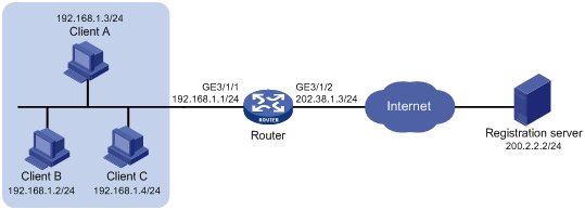
Procedure
# Specify IP addresses for the interfaces on the router. (Details not shown.)
# Specify the card in the specified slot as the primary node in failover group cgn.
<Router> system-view
[Router] failover group cgn id 1
[Router-failover-group-cgn] bind slot 2 primary
[Router-failover-group-cgn] quit
# Create public address group 0.
[Router] nat address-group 0
[Router-address-group-0] failover-group cgn
# Add the public IP addresses 202.38.1.2 and 202.38.1.3 to the NAT address group.
[Router-address-group-0] address 202.38.1.2 202.38.1.3
# Configure the port range as 1024 to 65535.
[Router-address-group-0] port-range 1024 65535
# Set the port block size to 300 and the extended port block number to 1.
[Router-address-group-0] port-block block-size 300 extended-block-number 1
[Router-address-group-0] quit
# Configure an ACL to identify packets from subnet 192.168.1.0/24.
[Router] acl basic 2000
[Router-acl-ipv4-basic-2000] rule permit source 192.168.1.0 0.0.0.255
[Router-acl-ipv4-basic-2000] quit
# Configure traffic class cgn and traffic behavior cgn to redirect packets matching ACL 2000 to failover group cgn.
[Router] traffic classifier cgn
[Router-classifier-cgn] if-match acl 2000
[Router-classifier-cgn] quit
[Router] traffic behavior cgn
[Router-behavior-cgn] redirect failover-group cgn
[Router-behavior-cgn] quit
# Configure a QoS policy and associate the traffic class with the traffic behavior.
[Router] qos policy cgn
[Router-qospolicy-cgn] classifier cgn behavior cgn
[Router-qospolicy-cgn] quit
# Apply the QoS policy to the inbound traffic on GigabitEthernet 3/1/1.
[Router] interface gigabitethernet 3/1/1
[Router-GigabitEthernet3/1/1] qos apply policy cgn inbound
[Router-GigabitEthernet3/1/1] quit
# Enable outbound NAT on GigabitEthernet 3/1/2.
[Router] interface gigabitethernet 3/1/2
[Router-GigabitEthernet3/1/2] nat outbound 2000 address-group 0
[Router-GigabitEthernet3/1/2] quit
# Configure a failover group to process session-based services. Traffic permitted by ACL 2000 are redirected to the primary node of failover group cgn for service processing.
[Router] session service-location acl 2000 failover-group cgn
# Enable flow-triggered port block assignment.
[Router] nat port-block flow-trigger enable
Verifying the configuration
# Verify that Host A can access external servers, but Host B and Host C cannot. (Details not shown.)
# Display all NAT configuration.
[Router] display nat all
NAT address group information:
Totally 1 NAT address groups.
Address group 0:
Port range: 1024-65535
Port block size: 300
Extended block number: 1
Failover group name: cgn
Address information:
Start address End address
202.38.1.2 202.38.1.3
NAT outbound information:
Totally 1 NAT outbound rules.
Interface: GigabitEthernet3/1/2
ACL: 2000 Address group: 0 Port-preserved: N
NO-PAT: N Reversible: N
Service card: ---
Config status: Active
NAT logging:
Log enable : Disabled
Flow-begin : Disabled
Flow-end : Disabled
Flow-active : Disabled
Port-block-assign : Disabled
Port-block-withdraw : Disabled
Port-alloc-fail : Enabled
Port-block-alloc-fail : Disabled
Port-usage : Disabled
Port-block-usage : Enabled(40%)
NAT mapping behavior:
Mapping mode : Connection-dependent
NAT ALG:
DNS : Disabled
FTP : Enabled
H323 : Disabled
ICMP-ERROR : Enabled
ILS : Disabled
MGCP : Disabled
NBT : Disabled
PPTP : Disabled
RTSP : Enabled
RSH : Disabled
SCCP : Disabled
SIP : Disabled
SQLNET : Disabled
TFTP : Disabled
XDMCP : Disabled
# Display NAT statistics.
[Router] display nat statistics slot 2
Slot 2:
Total session entries: 0
Total EIM entries: 0
Total inbound NO-PAT entries: 0
Total outbound NO-PAT entries: 0
Total static port block entries: 0
Total dynamic port block entries: 430
Active static port block entries: 0
Active dynamic port block entries: 1
Example: Configuring DS-Lite B4 address translation
Network configuration
As shown in Figure 32, configure DS-Lite tunneling and NAT to allow the DS-Lite host to access the IPv4 network over the IPv6 network.
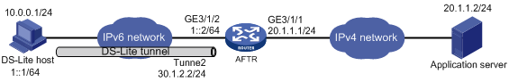
Procedure
Before configuration, make sure the DS-Lite host and AFTR can reach each other through IPv6.
1. Configure the AFTR:
# Specify an IPv4 address for GigabitEthernet 3/1/1.
<Router> system-view
[Router] interface gigabitethernet 3/1/1
[Router-GigabitEthernet3/1/1] ip address 20.1.1.1 24
[Router-GigabitEthernet3/1/1] quit
# Specify an IPv6 address for GigabitEthernet 3/1/2.
[Router] interface gigabitethernet 3/1/2
[Router-GigabitEthernet3/1/2] ipv6 address 1::2 64
[Router-GigabitEthernet3/1/2] quit
# Create a tunnel interface on the AFTR.
[Router] interface tunnel 2 mode ds-lite-aftr
# Specify an IP address for the tunnel interface.
[Router-Tunnel2] ip address 30.1.2.2 255.255.255.0
# Specify GigabitEthernet 3/1/2 as the source interface for the tunnel.
[Router-Tunnel2] source gigabitethernet 3/1/2
[Router-Tunnel2] quit
# Enable DS-Lite tunneling on GigabitEthernet 3/1/1.
[Router] interface gigabitethernet 3/1/1
[Router-GigabitEthernet3/1/1] ds-lite enable
[Router-GigabitEthernet3/1/1] quit
# Specify the card in the specified slot as the primary node in failover group cgn.
[Router] failover group cgn id 1
[Router-failover-group-cgn] bind slot 2 primary
[Router-failover-group-cgn] quit
# Create public address group 0.
[Router] nat address-group 0
[Router-address-group-0] failover-group cgn
# Add public IP addresses 20.1.1.11 and 20.1.1.12 to the NAT address group.
[Router-address-group-0] address 20.1.1.11 20.1.1.12
# Configure the port range as 1024 to 65535.
[Router-address-group-0] port-range 1024 65535
# Set the port block size to 300.
[Router-address-group-0] port-block block-size 300
[Router-address-group-0] quit
# Configure an IPv6 ACL to identify packets from subnet 1::/64.
[Router] acl ipv6 basic 2100
[Router-acl-ipv4-basic-2100] rule permit source 1::/64
[Router-acl-ipv4-basic-2100] quit
# Configure traffic class cgn and traffic behavior cgn to redirect packets matching IPv6 ACL 2100 to failover group cgn.
[Router] traffic classifier cgn
[Router-classifier-cgn] if-match acl ipv6 2100
[Router-classifier-cgn] quit
[Router] traffic behavior cgn
[Router-behavior-cgn] redirect failover-group cgn
[Router-behavior-cgn] quit
# Configure a QoS policy and associate the traffic class with the traffic behavior.
[Router] qos policy cgn
[Router-qospolicy-cgn] classifier cgn behavior cgn
[Router-qospolicy-cgn] quit
# Apply the QoS policy to the inbound traffic on GigabitEthernet 3/1/2.
[Router] interface gigabitethernet 3/1/2
[Router-GigabitEthernet3/1/2] qos apply policy cgn inbound
[Router-GigabitEthernet3/1/2] quit
# Configure DS-Lite B4 address translation on GigabitEthernet 3/1/1.
[Router] interface gigabitethernet 3/1/1
[Router-GigabitEthernet3/1/1] nat outbound ds-lite-b4 2100 address-group 0
[Router-GigabitEthernet3/1/1] quit
# Configure a failover group to process session-based services. Traffic permitted by ACL 2000 are redirected to the primary node of failover group cgn for service processing.
[Router] session service-location acl ipv6 2100 failover-group cgn
# Enable flow-triggered port block assignment.
[Router] nat port-block flow-trigger enable
2. Configure the DS-Lite host:
# Configure the IPv4 and IPv6 addresses of the DS-Lite host as 10.0.0.1 and 1::1/64. (Details not shown.)
# Configure a static route to the destination IPv4 network. (Details not shown.)
Verifying the configuration
# Use the display interface tunnel command to verify that the tunnel interface is up on the AFTR. (Details not shown.)
# Verify that the DS-Lite host can ping the IPv4 application server.
C:\> ping 20.1.1.2
Pinging 20.1.1.2 with 32 bytes of data:
Reply from 20.1.1.2: bytes=32 time=51ms TTL=255
Reply from 20.1.1.2: bytes=32 time=44ms TTL=255
Reply from 20.1.1.2: bytes=32 time=1ms TTL=255
Reply from 20.1.1.2: bytes=32 time=1ms TTL=255
Ping statistics for 20.1.1.2:
Packets: Sent = 4, Received = 4, Lost = 0 (0% loss),
Approximate round trip times in milli-seconds:
Minimum = 1ms, Maximum = 51ms, Average = 24ms
# Verify that the DS-Lite B4 address translation configuration is correct.
[Router] display nat outbound
NAT outbound information:
Totally 1 NAT outbound rules.
Interface: GigabitEthernet3/1/1
DS-Lite B4 ACL: 2100 Address group: 0 Port-preserved: N
NO-PAT: N Reversible: N
Config status: Active
# Verify that the DS-Lite B4 address translation configuration takes effect by checking the port block assignment.
[Router] display nat statistics slot 2
Slot 2:
Total session entries: 0
Total EIM entries: 0
Total inbound NO-PAT entries: 0
Total outbound NO-PAT entries: 0
Total static port block entries: 0
Total dynamic port block entries: 430
Active static port block entries: 0
Active dynamic port block entries: 1
# Verify that a NAT444 port block mapping has been created for the DS-Lite host.
[Router] display nat port-block dynamic ds-lite-b4 slot 2
Slot 2:
Local VPN DS-Lite B4 addr Global IP Port block Connections
--- 1::1 20.1.1.11 1024-1323 1
Total mappings found: 1
Example: Configuring inter-card hot backup for NAT and BRAS unification
Network configuration
As shown in Figure 33, the host, a PPPoE client, is connected to the Internet through the router. The router acts as the BRAS device, provides NAT services through CGN cards, and provides inter-card CGN backup through a failover group. Configure PPPoE server and NAT on the router to meet the following requirements:
· The PPPoE server cooperates with the RADIUS server to authenticate the host by using CHAP, and assigns a private IP address to the host.
· The PPPoE server uses shared key expert for secure RADIUS communication, and sends usernames with domain names to the RADIUS server.
· NAT cooperates with BRAS. NAT assigns a public IP address and a port block after the host passes authentication and obtains a private IP address.
· CGN 1 and CGN 2 form a failover group as the primary node and the secondary node, respectively. To implement inter-card CGN backup, enable hot backup for session service.

Procedure
1. Configure the RADIUS server (details not shown):
# Set the shared key for secure communication to expert.
# Add a user account and password for the PPP users connected to the router.
2. Configure the router:
# Create RADIUS scheme rad.
<Router> system-view
[Router] radius scheme rad
# Specify the IP address of the primary accounting server and the primary authentication server as 10.0.0.1.
[Router-radius-rad] primary accounting 10.0.0.1
[Router-radius-rad] primary authentication 10.0.0.1
# Set the shared key to plaintext expert for secure communication.
[Router-radius-rad] key accounting simple expert
[Router-radius-rad] key authentication simple expert
# Include domain names in the usernames sent to the RADIUS server.
[Router-radius-rad] user-name-format with-domain
[Router-radius-rad] quit
# Create user group user.
[Router] user-group user
[Router-ugroup-user] quit
# Create ISP domain cgn.
[Router] domain name cgn
# Specify RADIUS scheme rad for PPP user authentication, authorization, and accounting.
[Router-isp-cgn] authentication ppp radius-scheme rad
[Router-isp-cgn] authorization ppp radius-scheme rad
[Router-isp-cgn] accounting ppp radius-scheme rad
# Specify the user address type as private IPv4 address.
[Router-isp-cgn] user-address-type private-ipv4
# Configure the authorization attribute by specifying the user-group option in an ISP domain cgn.
[Router-isp-cgn] authorization-attribute user-group user
[Router-isp-cgn] quit
# Create a DHCP address pool and add IP addresses 10.210.0.2 to 10.210.0.255 to the pool.
[Router] dhcp server ip-pool 1
[Router-dhcp-pool-1] address range 10.210.0.2 10.210.0.255
# Configure interface Virtual-Template 1 to use CHAP for authentication and use DHCP address pool 1 for IP address assignment.
[Router] interface virtual-template 1
[Router-Virtual-Template1] ppp authentication-mode chap domain cgn
[Router-Virtual-Template1] remote address pool 1
[Router-Virtual-Template1] ip address 10.210.0.1 24
# Enable PPPoE server on GigabitEthernet 3/1/1 and bind the interface to Virtual-Template 1.
[Router] interface gigabitethernet 3/1/1
[Router-GigabitEthernet3/1/1] pppoe-server bind virtual-template 1
[Router-GigabitEthernet3/1/1] quit
# Configure ACL 3000 to identify packets from subnet 10.210.0.0/24.
[Router] acl advanced 3000
[Router-acl-ipv4-adv-3000] rule 0 permit ip source 10.210.0.0 0.0.0.255 user-group user
[Router-acl-ipv4-adv-3000] quit
# Configure failover group cgn.
[Router] failover group cgn id 1
[Router-failover-group-cgn] bind slot 2 primary
[Router-failover-group-cgn] bind slot 3 secondary
[Router-failover-group-cgn] quit
# Configure traffic class cgn and traffic behavior cgn to redirect packets matching ACL 3000 to failover group cgn.
[Router] traffic classifier cgn
[Router-classifier-cgn] if-match acl 3000
[Router-classifier-cgn] quit
[Router] traffic behavior cgn
[Router-behavior-cgn] redirect failover-group cgn
[Router-behavior-cgn] quit
# Configure a QoS policy and associate the traffic class with the traffic behavior.
[Router] qos policy cgn
[Router-qospolicy-cgn] classifier cgn behavior cgn
[Router-qospolicy-cgn] quit
# Apply the QoS policy to the inbound traffic on GigabitEthernet 3/1/1.
[Router] interface gigabitethernet 3/1/1
[Router-GigabitEthernet3/1/1] qos apply policy cgn inbound
[Router-GigabitEthernet3/1/1] quit
# Enable session synchronization.
[Router] session synchronization enable
# Specify failover group cgn for address group 1, add public address 111.8.0.200, specify the port range as 1024 to 65535, and set the port block size to 10.
[Router] nat address-group 1
[Router-address-group-1] failover-group cgn
[Router-address-group-1] port-block block-size 10
[Router-address-group-1] port-range 1024 65535
[Router-address-group-1] address 111.8.0.200 111.8.0.200
# Configure outbound dynamic NAT on GigabitEthernet 3/1/2 to use address group 1 to translate packets permitted by ACL 3000.
[Router] interface gigabitethernet 3/1/2
[Router-GigabitEthernet3/1/2] ip address 111.8.0.101 255.255.255.0
[Router-GigabitEthernet3/1/2] nat outbound 3000 address-group 1
[Router-GigabitEthernet3/1/2] quit
# Configure a failover group to process session-based services. Traffic permitted by ACL 3000 are redirected to the primary node of failover group cgn for service processing.
[Router] session service-location acl 3000 failover-group cgn
Verifying the configuration
# Initiate a connection from the PPPoE client by entering the username and password.
# Execute the display ppp access-user command to display PPP user information, including the private IP address, translated public IP address, and port block. (Details not shown.)
# Verify that a dynamic port block-based entry has been created for the user.
[Router] display nat port-block dynamic slot 2
Slot 2:
Local VPN Local IP Global IP Port block Connections Extend
--- 10.210.0.4 111.8.0.200 1024-1033 1 ---
Total mappings found: 1
# Verify that the primary node in failover group cgn provides services when the node operates correctly.
[Router] display failover group
Stateful failover local group information:
ID Name Primary Secondary Active status
1 cgn 2 3 Primary
# Verify that the secondary node in failover group cgn provides services when the primary node fails.
[Router] display failover group
Stateful failover local group information:
ID Name Primary Secondary Active status
1 cgn 2 3 Secondary
Example: Configuring centralized backup for distributed CGN deployment
Network configuration
As shown in Figure 34, Router A, Router B, and Router C reside in an AS. The host, a PPPoE client, is connected to the Internet through Router A. Router A provides NAT services through CGN cards. When the CGN card on Router A fails, the traffic is directed to the CGN card on Router B that is connected to Router C. Configure PPPoE server and CGN cards on the routers to meet the following requirements:
· The PPPoE server (Router A) cooperates with the RADIUS server to authenticate the host by using CHAP, and assigns a private IP address to the host.
· Router A uses shared key expert for secure RADIUS communication, and sends usernames with domain names to the RADIUS server.
· NAT cooperates with Router A. Router A assigns a private IP address The CGN card on Router A assigns a public IP address and a port block.
· When the CGN card on Router A fails, the CGN card on Router B assigns a public IP address and a port block.
· Router A, Router B, and Router C run IGP (for example, IS-IS) and BGP. The routers distribute private IP addresses and public IP addresses through IGP and BGP, respectively.
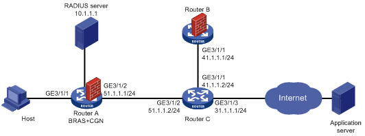
Procedure
1. Specify IP addresses and subnet masks for the interfaces on the routers. Set the IP address of Loopback 0 on Router B to 111.1.1.2/32. (Details not shown.)
2. Configure IGP and BGP. This example shows IBGP establishment between Router B and Router C. (Details not shown.)
3. Configure Router A:
# Configure the RADIUS server, set the shared key for secure communication to expert, and add a user account and password for the PPP users connected to the router. (Details not shown).
# Create RADIUS scheme rad.
<RouterA> system-view
[RouterA] radius scheme rad
# Specify the IP address of the primary accounting server and the primary authentication server as 10.0.0.1.
[RouterA-radius-rad] primary accounting 10.1.1.1
[RouterA-radius-rad] primary authentication 10.1.1.1
# Set the shared key to plaintext expert for secure communication.
[RouterA-radius-rad] key accounting simple expert
[RouterA-radius-rad] key authentication simple expert
# Include domain names in the usernames sent to the RADIUS server.
[RouterA-radius-rad] user-name-format with-domain
[RouterA-radius-rad] quit
# Create ISP domain cgn.
[RouterA] domain name cgn
# Specify RADIUS scheme rad for PPP user authentication, authorization, and accounting.
[RouterA-isp-cgn] authentication ppp radius-scheme rad
[RouterA-isp-cgn] authorization ppp radius-scheme rad
[RouterA-isp-cgn] accounting ppp radius-scheme rad
# Specify the user address type as private IPv4 address.
[RouterA-isp-cgn] user-address-type private-ipv4
[RouterA-isp-cgn] quit
# Create a DHCP address pool and add IP addresses 10.210.0.2 to 10.210.0.255 to the pool.
[RouterA] dhcp server ip-pool 1
[Router-dhcp-pool-1] address range 10.210.0.2 10.210.0.255
# Configure interface Virtual-Template 1 to use CHAP for authentication and use DHCP address pool 1 for IP address assignment.
[RouterA] interface virtual-template 1
[RouterA-Virtual-Template1] ppp authentication-mode chap domain cgn
[RouterA-Virtual-Template1] remote address pool 1
[RouterA-Virtual-Template1] ip address 10.210.0.1 24
[RouterA-Virtual-Template1] quit
# Enable PPPoE server on GigabitEthernet 3/1/1 and bind the interface to Virtual-Template 1.
[RouterA] interface gigabitethernet 3/1/1
[RouterA-GigabitEthernet3/1/1] pppoe-server bind virtual-template 1
[RouterA-GigabitEthernet3/1/1] quit
# Specify the card in the specified slot as the primary node in failover group cgn.
[RouterA] failover group cgn id 1
[RouterA-failover-group-cgn] bind slot 2 primary
[RouterA-failover-group-cgn] quit
# Configure ACL 3333 to identify packets from subnet 10.210.0.0/24.
[RouterA] acl advanced 3333
[RouterA-acl-ipv4-adv-3333] rule permit ip source 10.210.0.0 0.0.0.255
[RouterA-acl-ipv4-adv-3333] quit
# Configure traffic class cgn and traffic behavior cgn to redirect packets matching ACL 3333 to failover group cgn.
[RouterA] traffic classifier 3333
[RouterA-classifier-3333] if-match acl 3333
[RouterA-classifier-3333] quit
[RouterA] traffic behavior cgn
[RouterA-behavior-cgn] redirect failover-group cgn
[RouterA-behavior-cgn] quit
# Configure a QoS policy and associate the traffic class with the traffic behavior.
[RouterA] qos policy cgn
[RouterA-qospolicy-cgn] classifier 3333 behavior cgn
[RouterA-qospolicy-cgn] quit
# Apply the QoS policy to the inbound traffic on GigabitEthernet 3/1/1.
[RouterA] interface gigabitethernet 3/1/1
[RouterA-GigabitEthernet3/1/1] qos apply policy cgn inbound
[RouterA-GigabitEthernet3/1/1] quit
# Configure address group 0, add an address 100.64.216.251 to the group, and set the port block size to 300. Specify failover group cgn for address group 0.
[RouterA] nat address-group 0
[RouterA-address-group-0] address 100.64.216.251 100.64.216.251
[RouterA-address-group-0] port-range 1024 65535
[RouterA-address-group-0] port-block block-size 300
[RouterA-address-group-0] failover-group cgn
[RouterA-address-group-0] quit
# Configure outbound dynamic NAT on GigabitEthernet 3/1/2 to use address group 0 to translate packets permitted by ACL 3333.
[RouterA] interface gigabitethernet 3/1/2
[RouterA-GigabitEthernet3/1/2] ip address 51.1.1.1 24
[RouterA-GigabitEthernet3/1/2] isis enable 1
[RouterA-GigabitEthernet3/1/2] nat outbound 3333 address-group 0
[RouterA-GigabitEthernet3/1/2] quit
# Configure a failover group to process session-based services. Traffic permitted by ACL 3333 are redirected to the primary node of failover group cgn for service processing.
[RouterA] session service-location acl 3333 failover-group cgn
# Enable centralized backup for distributed CGN.
[RouterA] nat centralized-backup enable
4. Configure Router B:
# Establish an IBGP connection to Router C.
<RouterB> system-view
[RouterB] bgp 65009
[RouterB-bgp-default] router-id 2.2.2.2
[RouterB-bgp-default] peer 41.1.1.2 as-number 65009
[RouterB-bgp-default] peer 41.1.1.2 connect-interface loopback 0
[RouterB-bgp-default] address-family ipv4 unicast
[RouterB-bgp-default-ipv4] peer 41.1.1.2 enable
[RouterB-bgp-default-ipv4] quit
[RouterB-bgp-default] quit
# Configure failover group cgn.
[RouterB] failover group cgn id 1
[RouterB-failover-group-cgn] bind slot 2 primary
[RouterB-failover-group-cgn] quit
# Specify failover group cgn for address group 1, add public address 172.18.217.1 to 172.18.217.250, specify the port range as 1024 to 65535, and set the port block size to 300.
[RouterB] nat address-group 1
[RouterB-address-group-1] failover-group cgn
[RouterB-address-group-1] address 172.18.217.1 172.18.217.250
[RouterB-address-group-1] port-range 1024 65535
[RouterB-address-group-1] port-block block-size 300
[RouterB-address-group-1] quit
# Configure ACL 3333 to identify packets from subnet 10.210.0.0/24.
[RouterB] acl basic 3333
[RouterB-acl-ipv4-basic-3333] rule 0 permit ip source 10.210.0.0 0.0.255.255
[RouterB-acl-ipv4-basic-3333] quit
# Configure traffic class cgn and traffic behavior cgn to redirect packets matching ACL 3333 to failover group cgn.
[RouterB] traffic classifier 3333
[RouterB-classifier-3333] if-match acl 3333
[RouterB-classifier-3333] quit
[RouterB] traffic behavior cgn
[RouterB-behavior-cgn] redirect failover-group cgn
[RouterB-behavior-redirect] quit
# Configure a QoS policy and associate the traffic class with the traffic behavior.
[RouterB] qos policy cgn
[RouterB-qospolicy-cgn] classifier 3333 behavior cgn
[RouterB-qospolicy-cgn] quit
# Apply the QoS policy to the inbound traffic and enable outbound dynamic PAT. The source IP addresses of the packets permitted by ACL 3333 are translated into the addresses in address group 1.
[RouterB] interface gigabitethernet 3/1/1
[RouterB-GigabitEthernet3/1/1] qos apply policy cgn inbound
[RouterB-GigabitEthernet3/1/1] nat outbound 3333 address-group 1
[RouterB-GigabitEthernet3/1/1] quit
# Configure a failover group to process session-based services. Traffic permitted by ACL 3333 are redirected to the primary node of failover group cgn for service processing.
[RouterB] session service-location acl 3333 failover-group cgn
# Enable flow-triggered port block assignment.
[RouterB] nat port-block flow-trigger enable
5. Configure Router C:
# Establish an IBGP connection to Router B.
<RouterC> system-view
[RouterC] bgp 65009
[RouterC-bgp-default] router-id 3.3.3.3
[RouterC-bgp-default] peer 41.1.1.1 as-number 65009
[RouterC-bgp-default] address-family ipv4 unicast
[RouterC-bgp-default-ipv4] peer 41.1.1.1 enable
[RouterC-bgp-default-ipv4] quit
[RouterC-bgp-default] quit
# Configure ACL 3333 to identify packets from subnet 10.210.0.0/24.
[RouterC] acl basic 3333
[RouterC-acl-ipv4-basic-3333] rule 0 permit ip source 10.210.0.0 0.0.255.255
[RouterC-acl-ipv4-basic-3333] quit
# Create policy node ipv4. Set the next-hop address of packets matching ACL 3333 packets to 111.1.1.2.
[RouterC] policy-based-route ipv4 permit node 0
[RouterC-GigabitEthernet3/1/2] if-match acl 3333
[RouterC-GigabitEthernet3/1/2] apply next-hop 111.1.1.2
[RouterC-GigabitEthernet3/1/2] quit
# Apply policy ipv4 to packets forwarded by GigabitEthernet 3/1/2.
[RouterC] interface gigabitethernet 3/1/2
[RouterC-GigabitEthernet3/1/2] ip policy-based-route ipv4
[RouterC-GigabitEthernet3/1/2] quit
Verifying the configuration
# Initiate a connection from the PPPoE client by entering the username and password.
# Execute the display ppp access-user command to display PPP user information, including the private IP address, translated public IP address, and port block. (Details not shown.)
# Verify that a dynamic port block-based entry has been created for the user.
[RouterA] display nat port-block dynamic slot 2
Slot 2:
Local VPN Local IP Global IP Port block Connections Extend
--- 10.210.0.4 100.64.216.251 1024-1323 1 ---
Total mappings found: 1
# Remove the CGN card from Router A.
# Verify that a dynamic port block-based entry has been created on Router B after user login.
[RouterB] display nat port-block dynamic slot 2
Slot 2:
Local VPN Local IP Global IP Port block Connections Extend
--- 10.210.0.4 172.18.217.1 1024-1323 0 ---
Total mappings found: 1
Example: Configuring extended port block report for PPPoE users
Network configuration
As shown in Figure 35, the host, a PPPoE client, is connected to the Internet through the router. The router acts as the BRAS device and the NAT device. Configure PPPoE server and NAT on the router to meet the following requirements:
· The PPPoE server cooperates with the RADIUS server to authenticate the user by using CHAP, and assigns a private IP address to the user.
· The PPPoE server uses shared key expert for secure RADIUS communication, and sends usernames with domain names to the RADIUS server.
· NAT cooperates with BRAS. NAT assigns a public IP address and a pre-allocated port block to the user after the user passes authentication and obtains a private IP address.
· When pre-allocated port resources are used up, the router assigns an extended port block to subsequent user connections and reports the update to the RADIUS server for user tracing.

Procedure
# On the RADIUS server, set the shared key for secure communication to expert and add a user account and password for the PPP user. (Details not shown.)
# Create RADIUS scheme rad.
<Router> system-view
[Router] radius scheme rad
# Specify the IP address of the primary accounting server and the primary authentication server as 10.0.0.1, and the service port of the primary authentication server as 1812.
[Router-radius-rad] primary accounting 10.0.0.1
[Router-radius-rad] primary authentication 10.0.0.1 1812
# Set the shared key to plaintext expert for secure communication.
[Router-radius-rad] key authentication simple expert
# Include domain names in the usernames sent to the RADIUS server.
[Router-radius-rad] user-name-format with-domain
[Router-radius-rad] quit
# Create a user group named user.
[Router] user-group user
[Router-ugroup-user] quit
# Create ISP domain cgn.
[Router] domain name cgn
# Specify RADIUS scheme rad for PPP user authentication, authorization, and accounting.
[Router-isp-cgn] authentication ppp radius-scheme rad
[Router-isp-cgn] authorization ppp radius-scheme rad
[Router-isp-cgn] accounting ppp radius-scheme rad
# Specify the user address type as private IPv4 address. Success authentication of such users can trigger NAT.
[Router-isp-cgn] user-address-type private-ipv4
# Specify the user group as the user authorization attribute in ISP domain cgn.
[Router-isp-cgn] authorization-attribute user-group user
[Router-isp-cgn] quit
# Create DHCP address pool 1 and add IP addresses 10.210.0.2 to 10.210.0.255 to the pool.
[Router] dhcp server ip-pool 1
[Router-dhcp-pool-1] address range 10.210.0.2 10.210.0.255
# Configure interface Virtual-Template 1 to use CHAP for authentication and use DHCP address pool 1 for IP address assignment.
[Router] interface virtual-template 1
[Router-Virtual-Template1] ppp authentication-mode chap domain cgn
[Router-Virtual-Template1] remote address pool 1
[Router-Virtual-Template1] ip address 10.210.0.1 24
# Enable PPPoE server on GigabitEthernet 3/1/1 and bind the interface to Virtual-Template 1.
[Router] interface gigabitethernet 3/1/1
[Router-GigabitEthernet3/1/1] pppoe-server bind virtual-template 1
[Router-GigabitEthernet3/1/1] quit
# Create ACL 3000 to identify user packets from internal network 10.210.0.0/24.
[Router] acl advanced 3000
[Router-acl-ipv4-adv-3000] rule 0 permit source 10.210.0.0 0.0.0.255 user-group user
[Router-acl-ipv4-adv-3000] quit
# Configure a failover group.
<Router> system-view
[Router] failover group cgn id 1
[Router-failover-group-cgn] bind slot 3 primary
[Router-failover-group-cgn] bind slot 5 secondary
[Router-failover-group-cgn] quit
# Configure traffic class cgn, and configure traffic class cgn to redirect traffic matching ACL 3000 to failover group cgn.
[Router] traffic classifier cgn
[Router-classifier-cgn] if-match acl 3000
[Router-classifier-cgn] quit
[Router] traffic behavior cgn
[Router-behavior-cgn] redirect failover-group cgn
[Router-behavior-cgn] quit
# Create QoS policy cgn and associate the traffic class with the traffic behavior.
[Router] qos policy cgn
[Router-qospolicy-cgn] classifier cgn behavior cgn
[Router-qospolicy-cgn] quit
# Apply the QoS policy to the inbound traffic on GigabitEthernet 3/1/1.
[Router] interface gigabitethernet 3/1/1
[Router-GigabitEthernet3/1/1] qos apply policy cgn inbound
[Router-GigabitEthernet3/1/1] quit
# Create address group 1. Add public address 111.8.0.200, specify the port range as 1024 to 65535, and set the port block size to 10 and the number of extended port blocks to 5.
[Router] nat address-group 1
[Router-address-group-1] failover-group cgn
[Router-address-group-1] port-block block-size 10 extended-block-number 5
[Router-address-group-1] port-range 1024 65535
[Router-address-group-1] address 111.8.0.200 111.8.0.200
# Configure outbound dynamic NAT on GigabitEthernet 3/1/2. The source IP addresses of the packets permitted by ACL 3000 are translated into the addresses in address group 1.
[Router] interface gigabitethernet 3/1/2
[Router-GigabitEthernet3/1/2] ip address 111.8.0.101 255.255.255.0
[Router-GigabitEthernet3/1/2] nat outbound 3000 address-group 1
[Router-GigabitEthernet3/1/2] quit
# Enable the router to report mappings between user private IP addresses and extended port blocks to the RADIUS server.
[Router] nat extended-port-block report-radius enable
# Configure a failover group to process session-based services. Traffic permitted by ACL 3000 are redirected to the primary node of failover group cgn for service processing.
[Router] session service-location acl 3000 failover-group cgn
Verifying the configuration
# Verify that the user can user the username and password to access Internet through the router from the PPPoE client.
# Execute the display ppp access-user user-type pppoe verbose command on the router to verify extended port block information when the user is assigned an extended port block.
[Router] display ppp access-user user-type pppoe verbose
Basic:
Interface: BAS0
PPP index: 0x140002383
User ID: 0x20000002
Username: test
Domain: pppradius
Access interface: GigabitEthernet3/1/1
Service-VLAN/Customer-VLAN: -/-
VXLAN ID: -
MAC address: 0010-9400-0003
IP address: 10.210.0.4
IPv6 address: -
IPv6 PD prefix: -
IPv6 ND prefix: -
User address type: private-ipv4
VPN instance: -
Access type: PPPoE
Authentication type: CHAP
PPPoE:
Session ID: 1
AAA:
Authentication state: Authenticated
Authorization state: Authorized
Realtime accounting switch: Open
Realtime accounting interval: 120s
Login time: 2018-08-06 15:57:49:628
Accounting start time: 2018-08-06 15:57:49:647
Online time(hh:mm:ss): 00:33:52
Accounting state: Accounting
Acct start-fail action: Online
Acct update-fail action: Online
Acct quota-out action: Offline
Dual-stack accounting mode: Merge
Idle cut: 0 sec 0 bytes, direction: Both
Session timeout: -
Time remained: -
Traffic quota: -
Traffic remained: -
Redirect WebURL: -
ITA policy name: -
MRU: 1492 bytes
IPv4 MTU: 1492 bytes
IPv6 MTU: 1492 bytes
Subscriber ID: -
ACL&QoS:
User profile: -
Session group profile: -
User group acl: -
Inbound CAR: -
Outbound CAR: -
User inbound priority: -
User outbound priority: -
NAT:
Global IP address: 111.8.0.200
Port block: 1541-1650
Extended-block: 1651-1760/1761-1870/1871-1980/1981-2090/2091-2200
Flow Statistic:
IPv4 uplink packets/bytes: 639577859/81865963520
IPv4 downlink packets/bytes: 0/0
IPv6 uplink packets/bytes: 0/0
IPv6 downlink packets/bytes: 0/0
Example: Configuring dynamic port block mappings for unification of NAT and PPPoE user authentication
Network configuration
As shown in Figure 36, the host, a PPPoE client, is connected to the Internet through the router. The router acts as the BRAS device and the NAT device. Configure PPPoE server and NAT on the router to meet the following requirements:
· The PPPoE server cooperates with the RADIUS server to authenticate the user by using CHAP, and assigns a private IP address to the user.
· The PPPoE server uses shared key expert for secure RADIUS communication, and sends usernames with domain names to the RADIUS server.
· NAT cooperates with BRAS. NAT assigns a public IP address and a port block after the user passes authentication and obtains a private IP address.

Procedure
1. Assign IP addresses to interfaces as show in Figure 36. (Details not shown.)
2. On the RADIUS server, set the shared key for secure communication to expert and add a user account and password for the PPP user connected to the router. (Details not shown.)
3. Configure the router:
? Create RADIUS scheme.
# Create RADIUS scheme rad.
<Router> system-view
[Router] radius scheme rad
# Specify the IP address of the primary accounting server and the primary authentication server as 10.0.0.1, and the service port of the primary accounting server and the primary authentication server as 1813.
[Router-radius-rad] primary accounting 10.0.0.1 1813
[Router-radius-rad] primary authentication 10.0.0.1 1813
# Set the shared key to plaintext expert for secure communication.
[Router-radius-rad] key authentication simple expert
# Include domain names in the usernames sent to the RADIUS server.
[Router-radius-rad] user-name-format with-domain
[Router-radius-rad] quit
? Configure an ISP domain.
# Create ISP domain cgn.
[Router] domain name cgn
# Specify RADIUS scheme rad for PPP user authentication, authorization, and accounting.
[Router-isp-cgn] authentication ppp radius-scheme rad
[Router-isp-cgn] authorization ppp radius-scheme rad
[Router-isp-cgn] accounting ppp radius-scheme rad
# Specify the user address type as private IPv4 address. Success authentication of such users can trigger NAT.
[Router-isp-cgn] user-address-type private-ipv4
[Router-isp-cgn] quit
? Bind the load-sharing user group to the NAT instance.
# Create a user group named ugrp.
[Router] user-group ugrp
[Router-ugroup-ugrp] quit
# Bind user group ugrp to NAT instance inst.
[Router] domain name cgn
[Router-isp-cgn] user-group name ugrp bind nat-instance inst
[Router-isp-cgn] quit
? Configure PPPoE authentication.
# Create a DHCP address pool and add IP addresses 10.210.0.2 to 10.210.0.255 to the pool.
[Router] dhcp server ip-pool 1
[Router-dhcp-pool-1] address range 10.210.0.2 10.210.0.255
# Configure interface Virtual-Template 1 to use CHAP for authentication and use DHCP address pool 1 for IP address assignment.
[Router] interface virtual-template 1
[Router-Virtual-Template1] ppp authentication-mode chap domain cgn
[Router-Virtual-Template1] remote address pool 1
[Router-Virtual-Template1] ip address 10.210.0.1 24
[Router-Virtual-Template1] quit
# Enable PPPoE server on GigabitEthernet 3/1/1 and bind the interface to Virtual-Template 1.
[Router] interface gigabitethernet 3/1/1
[Router-GigabitEthernet3/1/1] pppoe-server bind virtual-template 1
[Router-GigabitEthernet3/1/1] quit
? Configure a failover group.
# Create failover group failgrp.
[Router] failover group failgrp id 1
# Specify the primary node and the secondary node for the failover group.
[Router-failover-group-failgrp] bind slot 2 primary
[Router-failover-group-failgrp] bind slot 3 secondary
[Router-failover-group-failgrp] quit
? Configure a service instance group.
# Create service instance group sgrp.
[Router] service-instance-group sgrp
# Associate the service instance group with failover group failgrp.
[Router-service-instance-group-sgrp] failover-group failgrp
[Router-service-instance-group-sgrp] quit
? Configure an advanced ACL.
# Create IPv4 advanced ACL 3000.
[Router] acl advanced 3000
# Configure rules for ACL 3000.
[Router-acl-ipv4-adv-3000] rule permit ip user-group ugrp
[Router-acl-ipv4-adv-3000] quit
? Configure a QoS policy to redirect IP packets matching user group ugrp to the NAT instance.
# Configure traffic class c1 to identify IP packets of users in user group ugrp.
[Router] traffic classifier c1
[Router-classifier-c1] if-match acl 3000
[Router-classifier-c1] quit
# Configure traffic class b1 to bind the matching traffic to NAT instance inst.
[Router] traffic behavior b1
[Router-behavior-b1] bind nat-instance inst
[Router-behavior-b1] quit
# Create QoS policy cb1 and associate the traffic class with the traffic behavior.
[Router] qos policy cb1
[Router-qospolicy-cb1] classifier c1 behavior b1
[Router-qospolicy-cb1] quit
# Apply QoS policy to the inbound traffic on GigabitEthernet 3/1/1.
[Router] interface gigabitethernet 3/1/1
[Router-GigabitEthernet3/1/1] qos apply policy cb1 inbound
[Router-GigabitEthernet3/1/1] quit
? Configure global NAT.
# Create address group 1. Add public address 111.8.0.200, specify the port range as 1024 to 65535, and set the port block size to 10.
[Router] nat address-group 1
[Router-address-group-1] port-block block-size 10
[Router-address-group-1] port-range 1024 65535
[Router-address-group-1] address 111.8.0.200 111.8.0.200
[Router-address-group-1] quit
# Create NAT instance inst.
[Router] nat instance inst id 1
# Associate service instance group sgrp with the NAT instance.
[Router-nat-instance-inst] service-instance-group sgrp
# Configure outbound dynamic NAT to use address group 1 to translate packets permitted by ACL 3000.
[Router-nat-instance-inst] nat outbound 3000 address-group 1
[Router-nat-instance-inst] quit
Verifying the configuration
# Initiate a connection from the PPPoE client by entering the username and password.
# Execute the display ppp access-user command to display PPP user information, including the private IP address, translated public IP address, and port block. (Details not shown.)
# Verify that a dynamic port block-based entry has been created for the user.
[Router] display nat port-block dynamic slot 2
Slot 2:
Local VPN Local IP Global IP Port block Connections Extend
--- 10.210.0.4 111.8.0.200 1314-1323 1 ---
Total mappings found: 1
Example: Configuring unification between IPoE Web authentication and CGN for advertisement or charge page push
Network configuration
As shown in Figure 37:
· The DHCP client is connected to the BRAS access device through IPoE at Layer 2.
· The BRAS access device acts as the DHCP server to assign private IP addresses to users.
· The advertisement push server, AAA server, and the portal server are on the public network. The CGN card on the BRAS device performs NAT.
· The AAA server performs a COA authorization to users whose charges are overdue to modify their user groups, push the charge notification pages to them. After the page push, the AAA server assigns the users to their original user groups. The advertisement push server also handles these users in the same way except that it pushes advertisements to them instead of the charge notification page.
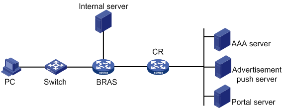
Procedure
1. Configure the DHCP server:
# Enable DHCP.
<BRAS> system-view
[BRAS] dhcp enable
# Create a DHCP address pool named pool1.
[BRAS] ip pool pool1
# Specify network 192.168.0.0/24 for dynamic address allocation, gateway address 192.168.0.1, and DNS server address 8.8.8.8.
[BRAS-ip-pool-pool1] network 192.168.0.0 24
[BRAS-ip-pool-pool1] gateway-list 192.168.0.1
[BRAS-ip-pool-pool1] dns-list 8.8.8.8
# Exclude IP address 192.168.0.1 from dynamic allocation.
[BRAS-ip-pool-pool1] forbidden-ip 192.168.0.1
[BRAS-ip-pool-pool1] quit
2. Configure global NAT:
? Configure a failover group.
# Create failover group nat.
[BRAS] failover group nat id 1
# Specify the primary node in the failover group.
[BRAS-failover-group-nat] bind slot 8 primary
Please wait for the operation to complete.................Done.
? Configure a NAT address group and bind it to the failover group.
# Create NAT address group 1, add public network 201.201.1.1/24, specify the port range as 1024 to 65535, and set the port block size to 10.
[BRAS] nat address-group 1
[BRAS-address-group-1] port-range 1024 65535
[BRAS-address-group-1] port-block block-size 1024
[BRAS-address-group-1] address 201.201.1.1 201.201.1.255
# Configure an ACL to identify packets from subnet 192.168.1.0/24.
[BRAS] acl advanced name cgn
[BRAS-acl-ipv4-adv-cgn] rule 1 permit ip source 192.168.1.0 0.0.0.255
? Configure a service instance group and a NAT instance.
# Create service instance group nat1, and associate failover group nat to with it.
[BRAS]service-instance-group nat1
[BRAS-service-instance-group-nat1]failover-group nat
# Create NAT instance nat1, associate service instance group nat1 with the NAT instance, and configure an outbound dynamic NAT rule.
[BRAS]nat instance nat1 id 1
[BRAS-nat-instance-nat1] service-instance-group nat1
[BRAS-nat-instance-nat1]nat outbound name cgn address-group 1
3. Configure the BRAS device:
? Assign IP addresses to interfaces. (Details not shown.)
? Configure a portal authentication server named newpt, and specify the server IP address as 4.4.4.5 and the plaintext key 123456.
[BRAS] portal server newpt
[BRAS-portal-server-newpt] ip 4.4.4.5 key simple 123456
[BRAS-portal-server-newpt] quit
? Specify 11111 as the HTTPS redirect listening port number.
[BRAS] http-redirect https-port 11111
4. Create local user groups:
# Create a preauthentication domain user group named web.
[BRAS] user-group web
New user group added.
[BRAS-ugroup-web] quit
# Create a Web authentication domain user group named ipoe_web.
[BRAS] user-group ipoe_web
New user group added.
[BRAS-ugroup-ipoe_web] quit
# Create a Web authentication domain user group named ipoe_web1.
[BRAS] user-group ipoe_web1
New user group added.
[BRAS-ugroup-ipoe_web] quit
? Configure ACLs for preauthentication.
# Create an IPv4 advanced ACL named web_permit to permit packets destined for the portal server, advertisement push server, and the AAA server from users in user group web.
[BRAS] acl advanced name web_permit
[BRAS-acl-ipv4-adv-web_permit] rule 0 permit ip destination 4.4.4.5 0 user-group web
[BRAS-acl-ipv4-adv-web_permit]rule 1 permit ip destination 212.1.170.178 0 user-group ipoe_web
[BRAS-acl-ipv4-adv-web_permit]rule 2 permit ip destination 212.1.170.175 0
[BRAS-acl-ipv4-adv-web_permit] quit
# Create an IPv4 advanced ACL named neiwang to permit packets destined for the internal network server from users in user group web.
[BRAS] acl advanced name neiwang
[BRAS-acl-ipv4-adv-neiwang] rule 0 permit ip destination 4.4.4.6 0 user-group web
[BRAS-acl-ipv4-adv-neiwang] quit
# Create an IPv4 advanced ACL named web_http to permit TCP packets with the destination port 80 (HTTP packets) from users in user groups web and ipoe_web1.
[BRAS] acl advanced name web_http
[BRAS-acl-ipv4-adv-web_http] rule 0 permit tcp destination-port eq www user-group web
[BRAS-acl-ipv4-adv-web_http] rule 1 permit tcp destination-port eq www user-group ipoe_web1
[BRAS-acl-ipv4-adv-web_http] quit
# Create an IPv4 advanced ACL named web_https to permit TCP packets with the destination port 443 (HTTPS packets) from users in user groups web and ipoe_web1.
[BRAS] acl advanced name web_https
[BRAS-acl-ipv4-adv-web_https] rule 0 permit tcp destination-port eq 443 user-group web
[BRAS-acl-ipv4-adv-web_https] rule 1 permit tcp destination-port eq 443 user-group ipoe_web1
[BRAS-acl-ipv4-adv-web_https] quit
# Create an IPv4 advanced ACL named ip to permit IP packets from users in user group web.
[BRAS] acl advanced name ip
[BRAS-acl-ipv4-adv-ip] rule 0 permit ip user-group web
[BRAS-acl-ipv4-adv-ip] quit
# Create an IPv4 advanced ACL named neiwang_out to permit IP packets from the internal network server in user group web.
[BRAS] acl advanced name neiwang_out
[BRAS-acl-ipv4-adv-neiwang_out] rule 0 permit ip source 4.4.4.6 0 user-group web
[BRAS-acl-ipv4-adv-neiwang_out] quit
# Create an IPv4 advanced ACL named web_out to permit IP packets from the portal server, advertisement push server, and AAA server in user group web.
[BRAS] acl advanced name web_out
[BRAS-acl-ipv4-adv-web_out] rule 0 permit ip source 4.4.4.5 0 user-group web
[BRAS-acl-ipv4-adv-web_out] rule 1 permit ip source 212.1.170.178 0 user-group ipoe_web
[BRAS-acl-ipv4-adv-web_out] rule 2 permit ip source 212.1.170.175 0
[BRAS-acl-ipv4-adv-web_out] quit
# Create an IPv4 advanced ACL named web_houyu to permit all user IP packets.
[BRAS] acl advanced name web_houyu
[BRAS-acl-ipv4-adv-web_houyu] rule 0 permit ip user-group ipoe_web
[BRAS-acl-ipv4-adv-web_houyu] rule 1 permit ip user-group ipoe_web1
[BRAS-acl-ipv4-adv-web_houyu] quit
? Configure traffic classes for preauthentication:
# Configure traffic class web_permit and specify ACL web_permit as the match criterion.
[BRAS] traffic classifier web_permit operator and
[BRAS-classifier-web_permit] if-match acl name web_permit
[BRAS-classifier-web_permit] quit
# Configure traffic class neiwang and specify ACL neiwang as the match criterion.
[BRAS] traffic classifier neiwang operator and
[BRAS-classifier-neiwang] if-match acl name neiwang
[BRAS-classifier-neiwang] quit
# Configure traffic class web_http and specify ACL web_http as the match criterion.
[BRAS] traffic classifier web_http operator and
[BRAS-classifier-web_http] if-match acl name web_http
[BRAS-classifier-web_http] quit
# Configure traffic class web_https and specify ACL web_https as the match criterion.
[BRAS] traffic classifier web_https operator and
[BRAS-classifier-web_https] if-match acl name web_https
[BRAS-classifier-web_https] quit
# Configure traffic class web_deny and specify ACL ip as the match criterion.
[BRAS] traffic classifier web_deny operator and
[BRAS-classifier-web_deny] if-match acl name ip
[BRAS-classifier-web_deny] quit
# Configure traffic class web_houyu and specify ACL web_houyu as the match criterion.
[BRAS] traffic classifier web_houyu operator and
[BRAS-classifier-web_houyu] if-match acl name web_houyu
[BRAS-classifier-web_houyu] quit
# Configure traffic class neiwang_out and specify ACL neiwang_out as the match criterion.
[BRAS] traffic classifier neiwang_out operator and
[BRAS-classifier-neiwang_out] if-match acl name neiwang_out
[BRAS-classifier-neiwang_out] quit
# Configure traffic class web_out and specify ACL web_out as the match criterion.
[BRAS] traffic classifier web_out operator and
[BRAS-classifier-web_out] if-match acl name web_out
[BRAS-classifier-web_out] quit
? Configure traffic behaviors:
# Configure traffic behavior web_permit to redirect traffic to the CGN card.
[BRAS] traffic behavior web_permit
[BRAS-behavior-web_permit] bind nat-instance nat1
[BRAS-behavior-web_permit] free account
[BRAS-behavior-web_permit] quit
# Configure traffic behavior neiwang to permit traffic to pass through.
[BRAS] traffic behavior neiwang
[BRAS-behavior-neiwang] filter permit
[BRAS-behavior-neiwang] quit
# Configure traffic behavior web_http to redirect HTTP packets to the CPU.
[BRAS] traffic behavior web_http
[BRAS-behavior-web_http] redirect http-to-cpu
[BRAS-behavior-web_http] quit
# Configure traffic behavior web_https to redirect HTTPS packets to the CPU.
[BRAS] traffic behavior web_https
[BRAS-behavior-web_https] redirect https-to-cpu
[BRAS-behavior-web_https] quit
# Configure traffic behavior web_deny to deny traffic.
[BRAS] traffic behavior web_deny
[BRAS-behavior-web_deny] filter deny
[BRAS-behavior-web_deny] free account
[BRAS-behavior-web_deny] quit
# Configure traffic behavior web_houyu to redirect the all matching IP packets to the CGN card.
[BRAS]traffic behavior web_houyu
[BRAS-behavior-web_houyu]bind nat-instance nat1
[BRAS-behavior-web_houyu]quit
# Configure traffic behavior neiwang_out to permit traffic to pass through.
[BRAS] traffic behavior neiwang_out
[BRAS-behavior-neiwang_out] filter permit
[BRAS-behavior-neiwang_out] quit
# Configure traffic behavior web_out to permit traffic to pass through.
[BRAS] traffic behavior web_out
[BRAS-behavior-web_out] filter permit
[BRAS-behavior-web_out] free account
[BRAS-behavior-web_out] quit
? Configure QoS policies:
# Configure a QoS policy named web.
[BRAS] qos policy web
# Associate traffic class web_permit with traffic behavior web_permit.
[BRAS-qospolicy-web] classifier web_permit behavior web_permit
# Associate traffic class neiwang with traffic behavior neiwang.
[BRAS-qospolicy-web] classifier neiwang behavior neiwang
# Associate traffic class web_http with traffic behavior web_http.
[BRAS-qospolicy-web] classifier web_http behavior web_http
# Associate traffic class web_https with traffic behavior web_https.
[BRAS-qospolicy-web] classifier web_https behavior web_https
# Associate traffic class web_deny with traffic behavior web_deny.
[BRAS-qospolicy-web] classifier web_deny behavior web_deny
# Associate traffic class web_houyu with traffic behavior web_houyu.
[BRAS-qospolicy-web] classifier web_houyu behavior web_houyu
[BRAS-qospolicy-web] quit
# Configure a QoS policy named out.
[BRAS] qos policy out
# Associate traffic class web_out with traffic behavior web_out.
[BRAS-qospolicy-out] classifier web_out behavior web_out
# Associate traffic class neiwang_out with traffic behavior neiwang_out.
[BRAS-qospolicy-out] classifier neiwang_out behavior neiwang_out
# Associate traffic class web_deny with traffic behavior web_deny.
[BRAS-qospolicy-out] classifier web_deny behavior web_deny
[BRAS-qospolicy-out] quit
? Apply QoS polices:
# Apply QoS Policy web to the inbound traffic globally.
[BRAS] qos apply policy web global inbound
# Apply QoS Policy out to the outbound traffic globally.
[BRAS] qos apply policy out global outbound
? Configure a RADIUS scheme:
# Create a RADIUS scheme named rs1.
[BRAS] radius scheme rs1
# Specify the IP address of the primary accounting server and the primary authentication server.
[BRAS-radius-rs1] primary authentication 4.4.4.5
[BRAS-radius-rs1] primary accounting 4.4.4.5
# Set the shared key to plaintext expert for secure communication.
[BRAS-radius-rs1] key authentication simple radius
[BRAS-radius-rs1] key accounting simple radius
# Exclude domain names from the usernames sent to the RADIUS server.
[BRAS-radius-rs1] user-name-format without-domain
[BRAS-radius-rs1] quit
? Configure the preauthentication domain and the Web authentication domain:
# Configure a preauthentication domain for IPoE users.
[BRAS] domain name dm1
[BRAS-isp-dm1] authentication ipoe none
[BRAS-isp-dm1] authorization ipoe none
[BRAS-isp-dm1] accounting ipoe none
# Specify the authorized address pool.
[BRAS-isp-dm1] authorization-attribute ip-pool pool1
# Specify the Web authentication page URL.
[BRAS-isp-dm1] web-server url http://4.4.4.5:8080/portal/
# Specify the user address type as private IPv4 address.
[BRAS-isp-dm1] user-address-type private-ipv4
# Add the user IP address to the Web server URL that is sent to the portal server.
[BRAS-isp-dm1] web-server url-parameter userip source-address
# Bind user group web to NAT instance nat1.
[BRAS-isp-dm1]user-group name web bind nat-instance nat1
[BRAS-isp-dm1] quit
# Configure authentication domain dm2 for IPoE user Web authentication.
[BRAS] domain name dm2
[BRAS-isp-dm2] authentication ipoe radius-scheme rs1
[BRAS-isp-dm2] authorization ipoe radius-scheme rs1
[BRAS-isp-dm2] accounting ipoe radius-scheme rs1
# Specify the authorized advertisement page URL.
[BRAS-isp-dm2] authorization-attribute url https://212.1.170.178:8080/
# Specify the user address type as private IPv4 address.
[BRAS-isp-dm2] user-address-type private-ipv4
# Bind user group ipoe_web to NAT instance nat1.
[BRAS-isp-dm2]user-group name ipoe_web bind nat-instance nat1
[BRAS-isp-dm2] quit
? Configure IPoE:
# Enable IPoE and configure the Layer 2 access mode.
[BRAS] interface gigabitethernet 3/1/2
[BRAS–GigabitEthernet3/1/2] ip subscriber l2-connected enable
# Specify the Web authentication method for IPoE users.
[BRAS–GigabitEthernet3/1/2] ip subscriber authentication-method web
The operation may cut all users on this interface. Continue?[Y/N]:y
# Specify preauthentication domain dm1 and Web authentication domain dm2.
[BRAS–GigabitEthernet3/1/2] ip subscriber pre-auth domain dm1
[BRAS–GigabitEthernet3/1/2] ip subscriber web-auth domain dm2
[BRAS–GigabitEthernet3/1/2] quit
5. Configure the RADIUS server:
a. Configure the access device:
i Log in to the IMC platform and click the User tab.
ii From the navigation tree, select User Access Policy > Access Device Management > Access Device to open the access device configuration page.
iii Click Add to open the page as shown in Figure 38.
iv Enter the shared key radius.
v Use the default settings for other parameters.
Figure 38 Adding an access device

vi Click Add Manually in the Device List area to open the page as shown in Figure 39.
vii Enter the access device's IP address 4.4.4.2.
viii Click OK.
Figure 39 Manually adding an access device

b. Add an access policy:
i Select User Access Policy > Access Policy from the navigation tree to open the access policy page.
ii Click Add to open the page as shown in Figure 40.
iii Enter the access policy name AccessPolicy.
iv Use the default settings for other parameters.
Figure 40 Adding an access policy
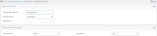
c. Adding an access service:
i From the navigation tree, select User Access Policy > Access Service to open the access service page.
ii Click Add to open the page as shown in Figure 41.
iii Enter service name IPoE_Server.
iv Select AccessPolicy from the default access policy list.
v Use the default settings for other parameters.
Figure 41 Adding an access service

d. Add a user:
i From the navigation tree, select User Management > Add User to open the adding user page, as shown in Figure 42.
ii Enter username IPoE_Web001 and user ID 001.
iii Click OK.
Figure 42 Adding an access user

e. Add an access user:
iv From the navigation tree, select Access User > All Access Users.
v Click Add to open the page as shown in Figure 43.
vi Select IPoE_Web001 for the username.
vii Enter account name user1.
viii Enter password pass1.
ix Select access service IPoE_Server.
Figure 43 Adding an access user
6. Configure the portal server:
a. Configure the portal homepage:
i From the navigation tree, select User Access Policy > Portal Service > Server to open the portal server configuration page, as shown in Figure 44.
ii Click OK.
Figure 44 Portal server configuration page
b. Configure portal authentication IP address range:
i From the navigation tree, select User Access Policy > Portal Service > IP Group to open the portal IP address group configuration page.
ii Click Add to open the page as shown in Figure 45.
iii Enter the IP group name IPoE_Web_User.
iv Enter the start IP address (192.168.0.1) and end IP address (192.168.0.255) of the IP group. Make sure the host IP address is in the IP group.
v Click OK.
c. Add a portal device:
i From the navigation tree, select User Access Policy > Portal Service > Device.
ii Click Add to open the page as shown in Figure 46.
iii Enter device name NAS.
iv Enter the IP address of the portal packets' outgoing interface GigabitEthernet 3/1/1 (4.4.4.2).
v Enter key 123456.
vi Select Directly Connect for access method.
vii Use default settings for other parameters.
viii Click OK.
Figure 46 Adding a portal device

d. Configure a port group:
i Access the portal device list on the User Access Policy > Portal Service > Device page, as shown in Figure 47.

ii
Click the Port Group icon ![]() in the
Operation column for the portal device.
in the
Operation column for the portal device.
iii Click Add to open the page as shown in Figure 48.
iv Enter port group name group.
v Select IP group IPoE_Web_User. (Make sure the IP address that the user uses for network access is in the selected IP group). Select NAT for Action, and add the network segment for address translation.
vi Use default settings for other parameters.
vii Click OK.
Figure 49 Adding a IP address group
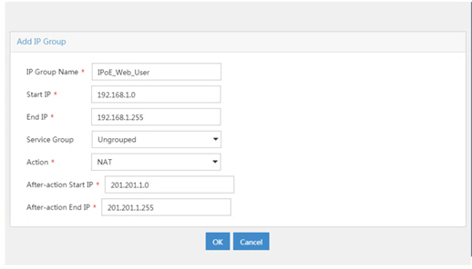
Verifying the configuration
# Display IPoE session information to verify that the host has passed preauthentication and obtained IP address 192.168.0.2.
[BRAS] display access-user auth-type pre-auth
UserID Interface IP address MAC address S-/C-VLAN
Username IPv6 address Access type
0x33d GE3/1/2 192.168.0.2 0015-e947-f4d4 -/-
0015e947f4d4 - L2 IPoE dynamic
# Enter the username and password and initiate Web authentication on the Web login page that opens after preauthentication.
# Display IPoE session information to verify that the host has passed Web authentication and come online.
[BRAS] display access-user auth-type web-auth
UserID Interface IP address MAC address S-/C-VLAN
Username IPv6 address Access type
0x33d GE3/1/2 192.168.0.2 0015-e947-f4d4 -/-
user1 - Web auth
Example: Configuring unification between PPPoE user authentication and NAT for advertisement push
Network configuration
As shown in Figure 50, the host, a PPPoE client, is connected to the Internet through the router. The router acts as the BRAS device and provides network access services and NAT services. Configure PPPoE server and NAT on the router to meet the following requirements:
· The PPPoE server cooperates with the RADIUS server to perform CHAP authentication, and assigns a private IP address to the host by using a DHCP address pool.
· The router uses shared key expert for secure RADIUS communication, and sends usernames with domain names to the RADIUS server. Advertisements are pushed to the user when the user accesses the network.
· NAT cooperates with BRAS. NAT assigns a public IP address and a port block to the host after the host passes authentication and obtains a private IP address.
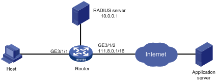
Procedure
1. Assign IP addresses to interfaces as show in Figure 50. (Details not shown.)
2. On the RADIUS server, set the shared key to expert for secure communication and add a PPP user account and password. (Details not shown.)
3. Configure the router:
? Configure a RADIUS scheme:
# Create RADIUS scheme rad.
<Router> system-view
[Router] radius scheme rad
# Specify the IP address of the primary accounting server and the primary authentication server as 10.0.0.1, and the port of the primary accounting server and the primary authentication server as 1813.
[Router-radius-rad] primary accounting 10.0.0.1 1813
[Router-radius-rad] primary authentication 10.0.0.1 1813
# Set the shared key to plaintext expert for secure communication.
[Router-radius-rad] key authentication simple expert
# Set real-time accounting interval to 10 minutes.
[Router-radius-rad] timer realtime-accounting 10
# Include domain names in the usernames sent to the RADIUS server.
[Router-radius-rad] user-name-format with-domain
[Router-radius-rad] quit
? Configure global NAT:
# Create NAT address group 0, add public addresses 202.38.1.2 and 202.38.1.3, specify the port range as 1024 to 65535, and set the port block size to 300.
[Router] nat address-group 0
[Router-address-group-0] address 202.38.1.2 202.38.1.3
[Router-address-group-0] port-range 1024 65535
[Router-address-group-0] port-block block-size 300
[Router-address-group-0] quit
# Create NAT instance nat, associate it with service instance group sgrp and configure an outbound dynamic NAT rule.
[Router] nat instance nat id 1
[Router-nat-instance-nat] service-instance-group sgrp
[Router-nat-instance-nat] nat outbound 3000 address-group 0
? Configure an ISP domain:
# Create an ISP domain named cgn.
[Router] domain name cgn
# Specify the authorized address pool, and the authorized advertisement page URL.
[Router-isp-cgn] authorization-attribute ip-pool nat
[Router-isp-cgn] authorization-attribute url http://4.4.4.4
[Router-isp-cgn] authorization-attribute redirect-times 10
# Specify RADIUS scheme rad for PPP user authentication, authorization, and accounting.
[Router-isp-cgn] authentication ppp radius-scheme rad
[Router-isp-cgn] authorization ppp radius-scheme rad
[Router-isp-cgn] accounting ppp radius-scheme rad
# Specify the user address type as private IPv4 address. Success authentication of such users can trigger NAT.
[Router-isp-cgn] user-address-type private-ipv4
[Router-isp-cgn] quit
# Bind user group pre to NAT instance nat.
[Router-isp-cgn] user-group name pre bind nat-instance nat
[Router-isp-cgn] quit
# Create an ISP domain named web.
[Router] domain name web
# Specify the authorized address pool.
[Router-isp-web] authorization-attribute ip-pool nat
# Specify RADIUS scheme rad for PPP user authentication, authorization, and accounting.
[Router-isp-web] authentication ppp radius-scheme rad
[Router-isp-web] authorization ppp radius-scheme rad
[Router-isp-web] accounting ppp radius-scheme rad
# Specify the user address type as private IPv4 address. Success authentication of such users can trigger NAT.
[Router-isp-web] user-address-type private-ipv4
# Bind user group web to NAT instance nat.
[Router-isp-web] user-group name web bind nat-instance nat
[Router-isp-web] quit
# Create user groups pre and web.
[Router] user-group pre
[Router] user-group web
[Router-ugroup-ugrp] quit
? Configure DHCP:
# Enable DHCP.
[Router] dhcp enable
# Create DHCP address pool nat, specify gateway address 3.3.0.1, and specify network segment 3.3.0.0/16 for dynamic address allocation.
[Router] dhcp server ip-pool nat
[Router -dhcp-pool-cp] gateway-list 3.3.0.1
[Router -dhcp-pool-cp] network 3.3.0.0 mask 255.255.0.0
[Router -dhcp-pool-cp] forbidden-ip 3.3.0.1
[Router -dhcp-pool-cp] quit
# Configure interface Virtual-Template 1 to use CHAP for authentication and use DHCP address pool nat for IP address assignment.
[Router] interface virtual-template 1
[Router-Virtual-Template1] ppp authentication-mode chap
[Router-Virtual-Template1] ppp account-statistics enable
[Router-Virtual-Template1] quit
# Enable PPPoE server on GigabitEthernet 3/1/1 and bind the interface to Virtual-Template 1.
[Router] interface gigabitethernet 3/1/1
[Router-GigabitEthernet3/1/1] port link-mode route
[Router-GigabitEthernet3/1/1] pppoe-server bind virtual-template 1
[Router-GigabitEthernet3/1/1] quit
? Configure a failover group:
# Create failover group failgrp.
[Router] failover group failgrp id 1
# Specify slot 2 and slot 3 as the primary node and secondary node in the failover group, respectively.
[Router-failover-group-failgrp] bind slot 2 primary
[Router-failover-group-failgrp] bind slot 3 secondary
[Router-failover-group-failgrp] quit
? Configure a service instance group:
# Create service instance group sgrp.
[Router] service-instance-group sgrp
# Associate service instance group sgrp with failover group failgrp.
[Router-service-instance-group-sgrp] failover-group failgrp
[Router-service-instance-group-sgrp] quit
? Create ACLs for preauthentication:
# Create IPv4 advanced ACL 3000.
[Router] acl advanced 3000
[Router-acl-ipv4-adv-3000] rule 0 permit ip source 3.3.0.0 0.255.255.255
[Router-acl-ipv4-adv-3000] quit
# Create IPv4 advanced ACL web_http to permit HTTP packets destined for port numbers 80 and 8080 from users in user group pre.
[Router] acl advanced name web_http
[Router -acl-ipv4-adv-web_http] rule 0 permit tcp destination-port eq www user-group pre
[Router -acl-ipv4-adv-web_http] rule 1 permit tcp destination-port eq 8080 user-group pre
[Router-acl-ipv4-adv-web_http] quit
# Create IPv4 advanced ACL web_https to permit HTTPS packets destined for port number 443 from users in user group pre.
[Router] acl advanced name web_https
[Router -acl-ipv4-adv-web_https] rule 0 permit tcp destination-port eq 443 user-group pre
[Router-acl-ipv4-adv-web_https] quit
# Create IPv4 advanced ACL web_pre to permit packets destined for the advertisement server from users in user group pre.
[Router] acl advanced name web_pre
[Router-acl-ipv4-adv-web_pre] rule 0 permit tcp destination 4.4.4.4 0 destination-port eq www user-group pre
[Router-acl-ipv4-adv-web_pre] rule 1 permit tcp destination 4.4.4.4 0 destination-port eq 8080 user-group pre
[Router-acl-ipv4-adv-web_pre] rule 2 permit tcp destination 4.4.4.4 0 destination-port eq 443 user-group pre
# Create IPv4 advanced ACL pre to permit IP packets from users in user group pre.
[Router] acl advanced name pre
[Router-acl-ipv4-adv-web] rule 0 permit ip user-group pre
[Router-acl-ipv4-adv-web] quit
# Create IPv4 advanced ACL web to permit IP packets from users in user group web.
[Router] acl advanced name web
[Router-acl-ipv4-adv-web] rule 0 permit ip user-group web
[Router-acl-ipv4-adv-web] quit
? Create a QoS policy:
# Configure traffic class pre and specify ACL pre as the match criterion.
[Router] traffic classifier pre operator or
[Router-classifier-pre] if-match acl name pre
[Router-classifier-pre] quit
# Configure traffic class web and specify ACL web as the match criterion.
[Router] traffic classifier web operator or
[Router-classifier-web] if-match acl name web
[Router-classifier-web] quit
# Configure traffic class web_http and specify ACL web_http as the match criterion.
[Router] traffic classifier web_http operator or
[Router-classifier-web_http] if-match acl name web_http
[Router-classifier-web_http] quit
# Configure traffic class web_https and specify ACL web_https as the match criterion.
[Router] traffic classifier web_https operator or
[Router-classifier-web_https] if-match acl name web_https
[Router-classifier-web_https] quit
# Configure traffic class web_pre and specify ACL web_pre as the match criterion.
[Router] traffic classifier web_pre operator or
[Router-classifier-web_pre] if-match acl name web_pre
[Router-classifier-web_pre] quit
# Configure traffic behavior b1 to redirect traffic to the NAT instance.
[Router] traffic behavior b1
[Router-behavior-b1] bind nat-instance nat
[Router-behavior-b1] quit
# Configure traffic behavior web_http to redirect HTTP packets to the CPU.
[Router] traffic behavior web_http
[Router-behavior-web_http] redirect http-to-cpu
[Router-behavior-web_http] quit
# Configure traffic behavior web_https to redirect HTTPS packets to the CPU.
[Router] traffic behavior web_https
[Router-behavior-web_https] redirect https-to-cpu
[Router-behavior-web_https] quit
# Create QoS policy cb1, and associate traffic classes with traffic behaviors.
[Router] qos policy cb1
[Router-qospolicy-cb1] classifier web_pre behavior b1
[Router-qospolicy-cb1] classifier pre_http behavior web_http
[Router-qospolicy-cb1] classifier pre_https behavior web_https
[Router-qospolicy-cb1] classifier pre behavior b1
[Router-qospolicy-cb1] classifier web behavior b1
[Router-qospolicy-cb1] quit
# Apply QoS policy cb1 to the inbound traffic globally.
[Router] qos apply policy cb1 global inbound
Verifying the configuration
# Initiate a connection from the PPPoE client by entering the username and password.
# Execute the display ppp access-user command to display detailed information about the PPP access user, including the private IP address, translated public IP address, and port block. (Details not shown.)
# Verify that a dynamic port block-based entry has been created for the user.
[Router] display nat port-block dynamic slot 2
Slot 2:
Local VPN Local IP Global IP Port block Connections Extend
--- 3.3.0.2 202.38.1.2 1024-1323 1 ---
Total mappings found: 1
Example: Configuring intra-system hot backup for unification between global NAT and PPPoE authentication
Network configuration
As shown in Figure 33, the host, a PPPoE client, is connected to the Internet through the router. The router acts as the BRAS device, provides NAT services through CGN cards, and provides intra-system CGN backup through one failover group. Configure PPPoE server and NAT on the router to meet the following requirements:
· The PPPoE server cooperates with the RADIUS server to perform CHAP authentication, and assigns a private IP address to the host by using a DHCP address pool.
· The router uses shared key expert for secure RADIUS communication, and sends usernames with domain names to the RADIUS server.
· NAT cooperates with BRAS. NAT assigns a public IP address and a port block to the host after the host passes authentication and obtains a private IP address.
· The primary node (CGN 1) and the secondary node (CGN 2) form a failover group. To implement intra-system CGN backup, enable session synchronization.
Figure 51 Network diagram
Procedure
# On the RADIUS server, set the shared key for secure communication to expert, and add a PPP user account and password. (Details not shown.)
# Create RADIUS scheme rad.
<Router> system-view
[Router] radius scheme rad
# Specify the IP address of the primary accounting server and the primary authentication server as 10.0.0.1.
[Router-radius-rad] primary accounting 10.0.0.1
[Router-radius-rad] primary authentication 10.0.0.1
# Set the shared key to plaintext expert for secure communication.
[Router-radius-rad] key accounting simple expert
[Router-radius-rad] key authentication simple expert
# Include domain names in the usernames sent to the RADIUS server.
[Router-radius-rad] user-name-format with-domain
[Router-radius-rad] quit
# Create user group user.
[Router] user-group user
[Router-ugroup-user] quit
# Create ISP domain cgn.
[Router] domain name cgn
# Specify RADIUS scheme rad for PPP user authentication, authorization, and accounting.
[Router-isp-cgn] authentication ppp radius-scheme rad
[Router-isp-cgn] authorization ppp radius-scheme rad
[Router-isp-cgn] accounting ppp radius-scheme rad
# Bind user group user to NAT instance cgn.
[Router-isp-cgn] user-group name user bind nat-instance cgn
# Specify the user address type as private-DS address. Success authentication of such users can trigger NAT.
[Router-isp-cgn] user-address-type private-ds
# Specify the authorized address pool group pool1.
[Router-isp-cgn] authorization-attribute ip-pool-group pool1
[Router-isp-cgn] quit
# Create DHCP address pool 1 and specify IP address range 10.210.0.2 to 10.210.63.255.
[Router] dhcp server ip-pool 1
[Router-dhcp-pool-1] gateway-list 10.210.0.1 export-route
[Router-dhcp-pool-1] network 10.210.0.0 mask 255.255.192.0 export-route
[Router-dhcp-pool-1] address range 10.210.0.2 10.210.0.255
[Router-dhcp-pool-21] quit
# Create DHCP address pool 2 and specify IP address range 10.210.64.2 to 10.210.127.255.
[Router] dhcp server ip-pool 2
[Router-dhcp-pool-2] gateway-list 10.210.64.1 export-route
[Router-dhcp-pool-2] network 10.210.64.0 mask 255.255.192.0 export-route
[Router-dhcp-pool-2] address range 10.210.64.2 10.210.64.255
[Router-dhcp-pool-2] quit
# Configure a DHCP address pool group.
[Router] dhcp pool-group pool1
[Router-dhcp-pool-group-pool1] pool 1
[Router-dhcp-pool-group-pool1] pool 2
[Router-dhcp-pool-group-pool1] quit
# Configure ACL 3000 to identify packets from user group user on subnet 10.210.0.0/24.
[Router] acl advanced 3000
[Router-acl-ipv4-adv-3000] rule 0 permit ip source 10.210.0.0 0.0.127.255 user-group user
[Router-acl-ipv4-adv-3000] quit
# Configure ACL 3001 to identify packets from subnet 10.210.0.0/24.
[Router] acl advanced 3001
[Router-acl-ipv4-adv-3001] rule 0 permit ip source 10.210.0.0 0.0.127.255
[Router-acl-ipv4-adv-3001] quit
# Configure failover group cgn.
[Router] failover group cgn id 1
[Router-failover-group-cgn] bind slot 2 primary
[Router-failover-group-cgn] bind slot 3 secondary
[Router-failover-group-cgn] quit
# Configure traffic class cgn, and configure traffic behavior cgn to redirect traffic to NAT instance cgn.
[Router] traffic classifier cgn
[Router-classifier-cgn] if-match acl 3000
[Router-classifier-cgn] quit
[Router] traffic behavior cgn
[Router-behavior-cgn] bind nat-instance cgn
[Router-behavior-cgn] quit
# Configure a QoS policy and associate the traffic class with the traffic behavior.
[Router] qos policy cgn
[Router-qospolicy-cgn] classifier cgn behavior cgn
[Router-qospolicy-cgn] quit
# Apply the QoS policy to the inbound traffic globally.
[Router] qos apply policy cgn global inbound
[Router] quit
# Enable session synchronization.
[Router] session synchronization enable
[Router] session synchronization http
# Specify the Endpoint-Independent Mapping mode for PAT.
[Router] nat mapping-behavior endpoint-independent tcp udp
# Create NAT address group 1, add public address 111.8.0.200, specify the port range as 1024 to 65535, and set the port block size to 300.
[Router] nat address-group 1
[Router-address-group-1] port-block block-size 300
[Router-address-group-1] port-range 1024 65535
[Router-address-group-1] address 111.8.0.200 111.8.0.200
[Router-address-group-1] quit
# Associate service instance group cgn with failover group cgn.
[Router] service-instance-group cgn
[Router- service-instance-group-cgn] failover-group cgn
[Router- service-instance-group-cgn] quit
# Create NAT instance cgn, associate it with service instance group cgn, and configure an outbound dynamic NAT rule.
[Router] nat instance cgn id 1
[Router-nat-instance-cgn1] service-instance-group cgn
[Router-nat-instance-cgn1] nat outbound 3001 address-group 1
[Router-nat-instance-cgn1] quit
Verifying the configuration
# Initiate a connection from the PPPoE client by entering the username and password.
# Execute the display ppp access-user command to display detailed information about the PPP access user, including the private IP address, translated public IP address, and port block. (Details not shown.)
# Verify that a dynamic port block-based entry has been created for the user.
[Router] display nat port-block dynamic slot 2
Slot 2:
Local VPN Local IP Global IP Port block Connections Extend
--- 10.210.0.4 111.8.0.200 1024-1323 1 ---
Total mappings found: 1
# Display failover group information to verify that the primary node in the failover group processes services.
[Router] display failover group
Stateful failover local group information:
ID Name Primary Secondary Active status
1 cgn 2 3 Primary
# Display failover group information when the primary node in the failover group fails. The output displays that the secondary node in the failover group processes services.
[Router] display failover group
Stateful failover local group information:
ID Name Primary Secondary Active status
1 cgn 2 3 Secondary
Example: Configuring intra-system hot backup for unification between global NAT and PPPoE authentication (load sharing)
Network configuration
As shown in Figure 52, the host, a PPPoE client, is connected to the Internet through the router. The router acts as the BRAS device, provides NAT services through CGN cards, and provides intra-system CGN backup with two failover groups. Configure PPPoE server and NAT on the router to meet the following requirements:
· The PPPoE server cooperates with the RADIUS server to perform CHAP authentication, and assigns a private IP address to the host by using a DHCP address pool.
· The PPPoE server uses shared key expert for secure RADIUS communication, and sends usernames with domain names to the RADIUS server.
· NAT cooperates with BRAS. NAT assigns a public IP address and a port block to the host after the host passes authentication and obtains a private IP address.
· Create two failover groups by using CGN 1 and CGN 2. To implement intra-system CGN backup, enable session synchronization.
Procedure
# On the RADIUS server, set the shared key for secure communication to expert, and add a PPP user account and password. (Details not shown.)
# Create RADIUS scheme rad.
<Router> system-view
[Router] radius scheme rad
# Specify the IP address of the primary accounting server and the primary authentication server as 10.0.0.1.
[Router-radius-rad] primary accounting 10.0.0.1
[Router-radius-rad] primary authentication 10.0.0.1
# Set the shared key to plaintext expert for secure communication.
[Router-radius-rad] key accounting simple expert
[Router-radius-rad] key authentication simple expert
# Include domain names in the usernames sent to the RADIUS server.
[Router-radius-rad] user-name-format with-domain
[Router-radius-rad] quit
# Create user groups user1 and user2.
[Router] user-group user1
[Router-ugroup-user1] quit
[Router] user-group user2
[Router-ugroup-user2] quit
# Create ISP domain cgn.
[Router] domain name cgn
# Specify RADIUS scheme rad for PPP user authentication, authorization, and accounting.
[Router-isp-cgn] authentication ppp radius-scheme rad
[Router-isp-cgn] authorization ppp radius-scheme rad
[Router-isp-cgn] accounting ppp radius-scheme rad
# Bind user group user1 to NAT instance cgn1.
[Router-isp-cgn] user-group name user1 bind nat-instance cgn1
# Bind user group user2 to NAT instance cgn2.
[Router-isp-cgn] user-group name user2 bind nat-instance cgn2
# Specify the user address type as private-DS address. Success authentication of such users can trigger NAT.
[Router-isp-cgn] user-address-type private-ds
# Specify the authorized address pool group pool1.
[Router-isp-cgn] authorization-attribute ip-pool-group pool1
[Router-isp-cgn] quit
# Create DHCP address pool 1 and specify IP address range 10.210.0.2 to 10.210.63.255.
[Router] dhcp server ip-pool 1
[Router-dhcp-pool-1] gateway-list 10.210.0.1 export-route
[Router-dhcp-pool-1] network 10.210.0.0 mask 255.255.192.0 export-route
[Router-dhcp-pool-1] address range 10.210.0.2 10.210.0.255
[Router-dhcp-pool-21] quit
# Create DHCP address pool 2 and specify IP address range 10.210.64.2 to 10.210.127.255.
[Router] dhcp server ip-pool 2
[Router-dhcp-pool-2] gateway-list 10.210.64.1 export-route
[Router-dhcp-pool-2] network 10.210.64.0 mask 255.255.192.0 export-route
[Router-dhcp-pool-2] address range 10.210.64.2 10.210.64.255
[Router-dhcp-pool-2] quit
# Configure a DHCP address pool group.
[Router] dhcp pool-group pool1
[Router-dhcp-pool-group-pool1] pool 1
[Router-dhcp-pool-group-pool1] pool 2
[Router-dhcp-pool-group-pool1] quit
# Configure ACL 3000 to identify packets from users in user group user1 on subnet 10.210.0.0/24.
[Router] acl advanced 3000
[Router-acl-ipv4-adv-3000] rule 0 permit ip source 10.210.0.0 0.0.127.255 user-group user1
[Router-acl-ipv4-adv-3000] quit
# Configure ACL 3001 to identify packets from users in user group user2 on subnet 10.210.0.0/24.
[Router] acl advanced 3001
[Router-acl-ipv4-adv-3001] rule 0 permit ip source 10.210.0.0 0.0.127.255 user-group user2
[Router-acl-ipv4-adv-3001] quit
# Configure ACL 3010 to identify packets from subnet 10.210.0.0/24.
[Router] acl advanced 3010
[Router-acl-ipv4-adv-3010] rule 0 permit ip source 10.210.0.0 0.0.127.255
[Router-acl-ipv4-adv-3010] quit
# Configure failover group cgn1.
[Router] failover group cgn1 id 1
[Router-failover-group-cgn1] bind slot 2 primary
[Router-failover-group-cgn1] bind slot 3 secondary
[Router-failover-group-cgn1] quit
# Configure failover group cgn2.
[Router] failover group cgn2 id 2
[Router-failover-group-cgn2] bind slot 3 primary
[Router-failover-group-cgn2] bind slot 2 secondary
[Router-failover-group-cgn2] quit
# Configure traffic class cgn1, and configure traffic behavior cgn1 to redirect traffic that matches ACL 3000 to NAT instance cgn1.
[Router] traffic classifier cgn1 operator and
[Router-classifier-cgn1] if-match acl 3000
[Router-classifier-cgn1] quit
[Router] traffic behavior cgn1
[Router-behavior-cgn1] bind nat-instance cgn1
[Router-behavior-cgn1] quit
# Configure traffic class cgn2, and configure traffic behavior cgn2 to redirect traffic that matches ACL 3001 to NAT instance cgn2.
[Router] traffic classifier cgn2 operator and
[Router-classifier-cgn2] if-match acl 3001
[Router-classifier-cgn2] quit
[Router] traffic behavior cgn2
[Router-behavior-cgn2] bind nat-instance cgn2
[Router-behavior-cgn2] quit
# Configure a QoS policy and associate traffic classes with traffic behaviors.
[Router] qos policy cgn
[Router-qospolicy-cgn] classifier cgn1 behavior cgn1
[Router-qospolicy-cgn] classifier cgn2 behavior cgn2
[Router-qospolicy-cgn] quit
# Apply the QoS policy globally.
[Router] qos apply policy cgn global inbound
# Enable session synchronization.
[Router] session synchronization enable
[Router] session synchronization http
# Specify the Endpoint-Independent Mapping mode for PAT.
[Router] nat mapping-behavior endpoint-independent tcp udp
# Specify failover group cgn1 for address group 1, add public address 140.250.124.0, specify the port range as 1024 to 65535, and set the port block size to 300.
[Router] nat address-group 1
[Router-address-group-1] port-block block-size 300
[Router-address-group-1] port-range 1024 65535
[Router-address-group-1] address 140.250.124.0 140.250.124.255
[Router-address-group-1] quit
# Specify failover group cgn2 for address group 2, add public address 140.250.126.0, specify the port range as 1024 to 65535, and set the port block size to 300.
[Router] nat address-group 2
[Router-address-group-2] port-block block-size 300
[Router-address-group-2] port-range 1024 65535
[Router-address-group-2] address 140.250.126.0 140.250.126.255
[Router-address-group-2] quit
# Create service instance group cgn1 and associate it with failover group cgn1.
[Router] service-instance-group cgn1
[Router-service-instance-group-cgn1] failover-group cgn1
[Router-service-instance-group-cgn1] quit
# Create service instance group cgn2 and associate it with failover group cgn2.
[Router] service-instance-group cgn2
[Router-service-instance-group-cgn2] failover-group cgn2
[Router-service-instance-group-cgn2] quit
# Create NAT instance cgn1, associate it with service instance group cgn1, and configure an outbound dynamic NAT rule.
[Router] nat instance cgn1 id 1
[Router-nat-instance-cgn1] service-instance-group cgn1
[Router-nat-instance-cgn1] nat outbound 3010 address-group 1
[Router-nat-instance-cgn1] quit
# Create NAT instance cgn2, associate it with service instance group cgn2, and configure an outbound dynamic NAT rule.
[Router] nat instance cgn2 id 2
[Router-nat-instance-cgn2] service-instance-group cgn2
[Router-nat-instance-cgn2] nat outbound 3010 address-group 2
[Router-nat-instance-cgn2] quit
Verifying the configuration
# Initiate a connection from the PPPoE client by entering the username and password.
# Execute the display ppp access-user command to display detailed information about the PPP access user, including the private IP address, translated public IP address, and port block. (Details not shown.)
# Verify that a dynamic port block-based entry has been created for the user.
[Router] display nat port-block dynamic slot 2
Slot 2:
Local VPN Local IP Global IP Port block Connections Extend
--- 10.210.0.4 140.250.124.0 1024-1323 1 ---
--- 10.210.0.5 140.250.126.0 1024-1323 1 ---
Total mappings found: 2
# Display failover group information to verify that the primary nodes in failover groups process services.
[Router] display failover group
Stateful failover local group information:
ID Name Primary Secondary Active status
1 cgn1 2 3 Primary
2 cgn2 3 2 Primary
# Display failover group information when the primary nodes in failover groups fail. The output displays that the secondary nodes in failover groups process services.
[Router] display failover group
Stateful failover local group information:
ID Name Primary Secondary Active status
1 cgn1 2 3 Secondary
2 cgn2 3 2 Primary
# Display configuration of ISP domain cgn and load-sharing user group information in the domain.
[Router] display domain name cgn
Domain: cgn
Current state: Active
State configuration: Active
PPP authentication scheme: RADIUS=rad
PPP authorization scheme: RADIUS=rad
PPP accounting scheme: RADIUS=rad
Default authentication scheme: Local
Default authorization scheme: Local
Default accounting scheme: Local
Accounting start failure action: Online
Accounting update failure action: Online
Accounting quota out policy: Offline
Send accounting update:Yes
Service type: HSI
Session time: Exclude idle time
User address type: private-ds
DHCPv6-follow-IPv6CP timeout: 60 seconds
Dual-stack accounting method: Merge
NAS-ID: N/A
Service rate-limit mode: Separate
Web server URL : Not configured
Web server URL parameters : Not configured
Web server IPv4 address : Not configured
Web server IPv6 address : Not configured
Authorization attributes:
Idle cut: Disabled
IP pool group: pool1
IGMP access limit: 4
MLD access limit: 4
User group and NAT instance bindings:
user1 (1 users) cgn1
user2 (1 users) cgn2