- Table of Contents
-
- 14-Network Management and Monitoring Configuration Guide
- 00-Preface
- 01-System maintenance and debugging configuration
- 02-NQA configuration
- 03-NTP configuration
- 04-PTP configuration
- 05-Network synchronization configuration
- 06-SNMP configuration
- 07-RMON configuration
- 08-NETCONF configuration
- 09-CWMP configuration
- 10-EAA configuration
- 11-Process monitoring and maintenance configuration
- 12-Sampler configuration
- 13-Mirroring configuration
- 14-NetStream configuration
- 15-IPv6 NetStream configuration
- 16-Fast log output configuration
- 17-Flow log configuration
- 18-Information center configuration
- 19-GOLD configuration
- 20-Packet capture configuration
- 21-Flow monitor configuration
- Related Documents
-
| Title | Size | Download |
|---|---|---|
| 05-Network synchronization configuration | 120.31 KB |
Configuring network synchronization
Network synchronization tasks at a glance
Configuring clock reference selection
Setting an Sa bit for the SSM of BITS clocks
Setting the frequency of a BITS clock
Specifying a line clock input port
Configuring automatic reference selection parameters
Configuring the method for setting the SSM quality level of a clock source
Specifying an SSM quality level for a clock source
Controlling the use of SSM in automatic reference selection
Setting a priority for a clock source
Display and maintenance commands for network clock monitoring module
Network synchronization configuration examples
Example: Configuring network synchronization
Configuring synchronous Ethernet
System clock QL distribution and SyncE port input QL updating
Restrictions and guidelines: synchronous Ethernet configuration
Configuring SyncE on an Ethernet interface
Display and maintenance commands for SyncE
Synchronous Ethernet configuration examples
Example: Configuring synchronous Ethernet
Configuring network synchronization
About network synchronization
The network clock monitoring module provides network clock synchronization for all interface cards in the system. It ensures that all ports on the interface cards operate at the same clock rates for network synchronization.
The network clock monitoring module provides the following functions:
· Provides highly precise, reliable timing signal to all interface cards.
· Constantly monitors the signaling status on the interface cards.
· Selects a clock reference from available clock sources, and then distributes its timing signal to all interface cards.
· Performs phase lock to maintain a deterministic relationship between the input and output signals in frequency and phase.
Clock sources
The device supports the following clock sources:
· BITS—Building integrated timing supply (BITS) clock. The MPU has BITS ports to receive and send timing signals.
· Line clock—Timing signal extracted from the signal received on a WAN port from a higher-level device. The WAN port is called a line processing unit (LPU) port. Line timing signal is less precise than BITS timing signal.
· PTP—Timing signal obtained through PTP. PTP timing signal is less precise than BITS timing signal.
· Local clock source—38.88 MHz timing signal generated by a crystal oscillator on the clock daughter card. The local clock signal has the lowest precision.
Clock source levels
The level of a clock source is determined by its SSM quality level and priority.
SSM quality levels
The synchronization status message (SSM) is transmitted in a synchronization distribution trail to indicate the quality of the clock source. The following are the SSM quality levels supported by the device, from the highest to the lowest:
· PRC—G.811 primary reference clock.
· SSU-A—G.812 primary-level SSU.
· SSU-B—G.812 second-level SSU.
· SEC—SDH equipment clock.
· Unknown—Synchronization quality unknown.
· DNU—Do not use for synchronization.
Clock source priority
For a clock source to be selected as the clock reference, assign it a lower priority value than other clock sources. The lower the priority value, the better the clock source. For example, the clock source with a priority of 1 is better than the clock source with a priority of 3.
Clock reference selection
The network clock monitoring module supports automatic and manual clock reference selection.
Automatic reference selection
In an automatic reference selection process, the network clock monitoring module uses the SSM quality level, clock source priority, and clock source number to make a selection decision. The use of SSM in the automatic reference selection process is user configurable.
The selection process is as follows:
1. If SSM is enabled for automatic reference selection, the module selects the clock source with the highest SSM quality level.
2. If SSM is disabled for automatic reference selection, or clock sources have the same SSM quality level, the module selects the clock source with the lowest priority value. (A lower priority value indicates a better clock source.)
3. If the clock sources have the same priority, the module selects the clock source that has the lowest slot-number/subslot-number/port-number sequence.
After selecting the best reference, the network clock monitoring module distributes the selected timing signal to all interface cards, and locks the timing to the reference signal. When the traced timing signal is lost, the network clock monitoring module selects the next optimal clock reference. When the signal of the best clock source can be traced again, the module selects the best clock source to replace the less optimal clock source as the reference.
|
|
NOTE: A clock source will not be selected as the reference if the clock source is in one of the following situations: · The timing signal cannot be detected. · The clock source priority is 255. · The SSM quality level is DNU. |
Manual reference selection
If you specify a clock source as the reference, the network clock monitoring module does not change the clock reference automatically. When the signal of the specified clock reference is lost, the module changes to the holdover state. In this state, the module continues to distribute the signal of the clock reference to the interface cards.
Clock mode on a port
|
|
IMPORTANT: Set the clock mode to slave on the port connected to a SONET/SDH device, because the SONET/SDH clock is more precise. |
A port can operate in one of the following clock modes:
· Master—The port provides timing to the peer end. The timing signal is derived from the network clock monitoring module.
¡ If automatic reference selection is used, the timing signal is derived from the reference clock selected by the network clock monitoring module.
¡ If manual reference selection is used, the timing signal is derived from the manually specified clock reference.
¡ If the manually specified clock reference is not available, the port outputs the timing signal generated by the local clock.
· Slave—The port uses the timing signal received from the peer end. For the network clock monitoring module to extract timing signal from a port, you must place the port in slave clock mode. If the port is in master clock mode, the module does not extract the timing signal from the incoming traffic on the port.
Network synchronization tasks at a glance
To configure network synchronization, perform the following tasks:
1. Configuring clock reference selection
Enable automatic clock reference selection or manually select a clock reference.
2. (Optional.) Configuring BITS clocks
a. Setting an Sa bit for the SSM of BITS clocks
b. Setting the frequency of a BITS clock
3. (Optional.) Specifying a line clock input port
4. (Optional.) Configuring automatic reference selection parameters
¡ Configuring the method for setting the SSM quality level of a clock source
¡ Specifying an SSM quality level for a clock source
¡ Controlling the use of SSM in automatic reference selection
¡ Setting a priority for a clock source
Configuring clock reference selection
Restrictions and guidelines
To use the timing signal from an interface as the synchronization reference, you must also specify the interface as a line clock input port by using the network-clock lpuport command.
If manual reference selection is used, the SSM levels and priorities configured for the clock sources do not take effect.
Procedure
1. (Optional.) Verify that the clock source you want to select is in Normal state.
display network-clock source
Skip this step if you use automatic reference selection.
2. Enter system view.
system-view
3. Enable automatic reference selection or manually select a reference.
In standalone mode:
network-clock work-mode { auto | manual source { bits0 | bits1 | lpuport interface-type interface-number } }
In IRF mode:
network-clock chassis chassis-number work-mode { auto | manual source { bits0 | bits1 } }
network-clock
work-mode manual source lpuport interface-type
interface-number
By default, automatic reference selection is enabled.
4. (Optional.) Display the operating state of the network clock monitoring module.
display network-clock status
It takes time for the clock reference selection mode change to take effect. To verify the effectiveness of the change, you can also check the logs.
Configuring BITS clocks
Setting an Sa bit for the SSM of BITS clocks
About setting an Sa bit for the SSM of BITS clocks
Sa bits from Sa4 through Sa8 can be used to transmit the SSM quality level of BITS timing signal. Select one Sa bit as required by the network.
Procedure
1. Enter system view.
system-view
2. Specify an Sa bit for the SSM of a BITS clock.
In standalone mode:
network-clock source { bits0 | bits1 } sa-bit { sa4 | sa5 | sa6 | sa7 | sa8 }
In IRF mode:
network-clock chassis chassis-number source { bits0 | bits1 } sa-bit { sa4 | sa5 | sa6 | sa7 | sa8 }
By default, BITS clocks use Sa 4 to transmit the SSM.
Setting the frequency of a BITS clock
About setting the frequency of a BITS clock
You can set the frequency of a BITS clock to 2 Mbps or 2 MHz.
Procedure
1. Enter system view.
system-view
2. Set the frequency of a BITS clock.
In standalone mode:
network-clock source { bits0 | bits1 } frequency { bps-2m | hz-2m }
In IRF mode:
network-clock chassis chassis-number source { bits0 | bits1 } frequency { bps-2m | hz-2m }
By default, the frequency of a BITS clock is 2 Mbps.
Specifying a line clock input port
Restrictions and guidelines
Only main ports can be specified as line clock input ports. For the timing signal received on the line clock input port to be used for synchronization, you must set the port to operate in slave mode.
Procedure
1. Enter system view.
system view
2. Enter interface view.
interface interface-type interface-number
3. Set the clock mode to slave.
clock slave
By default, slave clock mode is enabled on ports.
4. Return to system view.
quit
5. Specify the port as a line clock input port.
network-clock lpuport interface-type interface-number
By default, no line clock input port is configured.
Configuring automatic reference selection parameters
Configuring the method for setting the SSM quality level of a clock source
About setting the SSM quality level of a clock source
The network clock monitoring module can use one of the following methods to assign an SSM quality level to the timing signal from a clock source:
· Uses the SSM quality level extracted from the received timing signal.
· Uses the SSM quality level manually assigned as described in "Specifying an SSM quality level for a clock source."
Procedure
1. Enter system view.
system-view
2. Configure the method for setting the SSM quality level of a clock source.
In standalone mode:
network-clock source { bits0 | bits1 | lpuport interface-type interface-number | ptp } forcessm { off | on }
In IRF mode:
¡ For BITS and PTP:
network-clock chassis chassis-number source { bits0 | bits1 | ptp } forcessm { off | on }
¡ For a link clock input port:
network-clock source lpuport interface-type interface-number forcessm { off | on }
By default, the quality level of a clock source is a user-defined value. The network clock monitoring module does not extract the quality level from the SSM sent by the clock source.
To extract the SSM quality level from the received timing signal, specify the off keyword. To use the manually assigned SSM quality level, specify the on keyword.
Specifying an SSM quality level for a clock source
Restrictions and guidelines
The SSM quality level you specify for a clock source takes effect only when manual SSM quality level assignment is enabled.
Procedure
1. Enter system view.
system-view
2. Assign an SSM quality level to a clock source.
In standalone mode:
network-clock source { bits0 | bits1 | lpuport interface-type interface-number | ptp } ssm { dnu | prc | sec | ssua | ssub | unknown }
In IRF mode:
network-clock chassis chassis-number source { bits0 | bits1 | ptp } ssm { dnu | prc | sec | ssua | ssub | unknown }
network-clock
source lpuport interface-type
interface-number ssm { dnu | prc | sec | ssua | ssub | unknown }
By default, all clock sources use the unknown SSM quality level.
DNU clock sources are excluded from automatic reference selection.
3. (Optional.) Display the operating state of the network clock monitoring module.
display network-clock source
It takes time for the SSM quality level change to take effect. To verify the effectiveness of the change, you can also check the logs.
Controlling the use of SSM in automatic reference selection
Procedure
1. Enter system view.
system-view
2. Configure the use of SSM quality level in automatic reference selection.
In standalone mode:
network-clock ssmcontrol { off | on }
In IRF mode:
network-clock chassis chassis-number ssmcontrol { off | on }
To ignore the SSM quality level in clock reference selection, specify the off keyword. To use the SSM quality level in clock reference selection, specify the on keyword.
By default, SSM quality level is ignored in the automatic reference selection process.
Setting a priority for a clock source
About the priority of a clock source
In an automatic reference selection process, the network clock monitoring module selects the optimal clock as a reference from all available clock sources.
Restrictions and guidelines
The lower the priority value, the better the clock source.
Procedure
1. Enter system view.
system-view
2. Set a priority for a clock source.
In standalone mode:
network-clock source { bits0 | bits1 | lpuport interface-type interface-number | ptp } priority
In IRF mode:
network-clock chassis chassis-number source { bits0 | bits1 | ptp } priority
network-clock source lpuport interface-type interface-number priority
By default, all clock sources have a priority of 255. None of the clock sources can be used in automatic clock reference selection.
Display and maintenance commands for network clock monitoring module
Execute display commands in any view.
|
Task |
Command |
|
Display the self-test result of the network clock monitoring module. |
In standalone mode: display network-clock self-test-result In IRF mode: display network-clock self-test-result [ chassis chassis-number ] |
|
Display the operating state of the network clock monitoring module. |
In standalone mode: display network-clock status In IRF mode: display network-clock status [ chassis chassis-number ] |
|
Display the states of clock sources. |
In standalone mode: display network-clock source In IRF mode: display network-clock source [ chassis chassis-number ] |
|
Display version information for the network clock monitoring module. |
In standalone mode: display network-clock version In IRF mode: display network-clock version [ chassis chassis-number ] |
|
Reset the state of the network clock monitoring module. |
In standalone mode: reset network-clock In IRF mode: reset network-clock [ chassis chassis-number ] |
Network synchronization configuration examples
Example: Configuring network synchronization
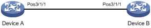
Network configuration
As shown in Figure 1, Device A obtains its timing signal from an external BITS clock.
Configure Device B to derive its timing from Device A through POS 3/1/1.
Procedure
1. On Device A:
# Specify the master clock mode on POS 3/1/1.
<DeviceA> system-view
[DeviceA] interface pos 3/1/1
[DeviceA-Pos3/1/1] clock master
2. On Device B:
# Specify POS 3/1/1 as a line clock input port.
<DeviceB> system-view
[DeviceB] network-clock lpuport pos 3/1/1
# Specify the slave clock mode on the POS interface.
[DeviceB] interface pos 3/1/1
[DeviceB-Pos3/1/1] clock slave
[DeviceB-Pos3/1/1] quit
# Specify the interface as the source to provide clock reference.
[DeviceB] network-clock work-mode manual source lpuport pos 3/1/1
[DeviceB] quit
Verifying the configuration
# Verify that the POS interface provides the network clock reference for Device B.
<DeviceB> display network-clock status
Mode : Manual
Reference : pos 3/1/1
Traced reference : pos 3/1/1
Lock mode : Locked
SSM output level : SSUB
SSM control enable: Off
Configuring synchronous Ethernet
About synchronous Ethernet
Synchronous Ethernet (SyncE) provides high-quality frequency synchronization on Ethernet at the physical layer. It can provide the same level of clock precision as SONET/SDH.
Transferring frequency signals at the physical layer, SyncE functions regardless of the network conditions such as congestion, packet loss, and delay.
Quality levels of clocks
SyncE devices use an Ethernet synchronization messaging channel (ESMC) to transmit the quality level (QL) of their system clocks. A SyncE device uses QL information to select the optimal clock reference from all available timing sources for its system clock.
The following are the QLs supported by the device, from the highest to the lowest:
· PRC—G.811 primary reference clock.
· SSU-A—G.812 primary-level SSU.
· SSU-B—G.812 second-level SSU.
· SEC—SDH equipment clock.
· DNU—Do not use for synchronization.
· UNK—Synchronization quality unknown.
DNU clock sources cannot participate in clock reference selection.
Clock reference selection
The system clock uses the clock reference selected with the highest QL from the following sources. If these sources have the same QL, the system clock selects the clock reference by priority, from the highest to the lowest:
· External clock sources.
· Line clock sources input from interfaces.
· Internal clock sources.
The system clock uses the QL of the selected reference. Clock reference selection process starts each time the QL of a source is updated.
|
|
NOTE: If QLs are the same on two interfaces, the clock source input from the lower-numbered interface has priority. |
System clock QL distribution and SyncE port input QL updating
Distribution of the system clock QL
When distributing the QL of the system clock, the system uses the following rules:
· If the clock reference is not from a SyncE port, the system distributes the QL out of all SyncE ports.
· If the clock reference is from a SyncE port, the system distributes the QL out of all SyncE ports except for the reference input port. To prevent timing loops, the sent QL is DNU on the timing reference input port.
Input QL updating on SyncE ports
The default input QL is DNU on a SyncE port. The port updates its input QL when it receives a quality level higher than DNU. The DNU level will be restored if the port does not receive ESMC packets within 5 seconds after the update.
Protocols and standards
· ITU-T G.781, Synchronization Layer Functions
· ITU-T G.813, Timing characteristics of SDH equipment slave clocks (SEC)
· ITU-T G.823, The control of jitter and wander within digital networks which are based on the 2048 kbit/s hierarchy
· ITU-T G.8261, Timing and Synchronization Aspects in Packet Networks
· ITU-T G.8262, Timing Characteristics of a Synchronous Ethernet Equipment Slave Clock (EEC)
· ITU-T G.8264/Y.1364, Distribution of Timing Information through Packet Networks
Restrictions and guidelines: synchronous Ethernet configuration
· Synchronous Ethernet is supported only on the following interfaces:
¡ Interfaces on a CEPC-XP48RX card.
¡ Interfaces operating in LAN mode on a CEPC-XP24LX card.
¡ Interfaces on the MIC-CP1L, NIC-CC1L, and NIC-CC2L subcards.
¡ Interfaces operating in LAN mode on the MIC-XP4L1, MIC-XP5L, MIC-XP5L1, and MIC-XP20L subcards.
For information about LAN mode, see Ethernet interface configuration in Interface Configuration Guide.
· Synchronous Ethernet operates correctly only when the device runs the CSR05SRP1L3 and CSR05SRP1P3 MPUs.
· The device does not support Synchronous Ethernet in an IRF fabric. For information about IRF, see Virtual Technologies Configuration Guide.
Configuring SyncE on an Ethernet interface
1. Enter system view.
system-view
2. Enter Layer 2 Ethernet interface view or Layer 3 Ethernet interface view.
interface interface-type interface-number
3. Enable the synchronous mode.
synchronous mode
By default, Ethernet interfaces are in the non-synchronous mode. An interface can participate in the clock reference selection only when it is in the synchronous mode.
4. Enable ESMC to transmit QL information.
esmc enable
By default, ESMC is disabled on Ethernet interfaces.
Display and maintenance commands for SyncE
Execute display commands in any view.
|
Task |
Command |
|
Display ESMC information. |
display esmc [ interface interface-type interface-number ] |
Synchronous Ethernet configuration examples
Example: Configuring synchronous Ethernet
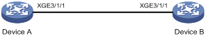
Network configuration
As shown in Figure 2, configure SyncE between the devices.
Procedure
# On Device A, enable the synchronous mode and ESMC on Ten-GigabitEthernet 3/1/1.
<DeviceA> system-view
[DeviceA] interface ten-gigabitethernet 3/1/1
[DeviceA-Ten-GigabitEthernet3/1/1] synchronous mode
[DeviceA-Ten-GigabitEthernet3/1/1] esmc enable
[DeviceA-Ten-GigabitEthernet3/1/1] quit
# On Device B, enable the synchronous mode and ESMC on Ten-GigabitEthernet 3/1/1.
<DeviceB> system-view
[DeviceB] interface ten-gigabitethernet 3/1/1
[DeviceB-Ten-GigabitEthernet3/1/1] synchronous mode
[DeviceB-Ten-GigabitEthernet3/1/1] esmc enable
[DeviceB-Ten-GigabitEthernet3/1/1] quit
Verifying the configuration
# Verify that ESMC is enabled on both Device A and Device B when they are connected to their respective clock references. The clock QLs of Device A and Device B are QL-PRC and QL-SEC, respectively. Device A provides more precise timing than Device B.
[DeviceA] display esmc
Interface : Ten-GigabitEthernet3/1/1
Mode : Synchronous
ESMC status : Enable
Port status : Up
Duplex mode : Full
QL received : QL-SEC
QL sent : QL-PRC
ESMC information packets received : 2195
ESMC information packets sent : 6034
ESMC event packets received : 1
ESMC event packets sent : 1
ESMC information rate : 1 packets/sec
ESMC expiration : 5 seconds
[DeviceB] display esmc
Interface : Ten-GigabitEthernet3/1/1
Mode : Synchronous
ESMC status : Enable
Port status : Up
Duplex mode : Full
QL received : QL-PRC
QL sent : QL-SEC
ESMC information packets received : 6034
ESMC information packets sent : 2195
ESMC event packets received : 1
ESMC event packets sent : 1
ESMC information rate : 1 packets/sec
ESMC expiration : 5 seconds
# Verify that QL information is exchanged correctly after synchronization between Device A and Device B. Ten-GigabitEthernet 3/1/1 on Device B becomes a reference input port. The clock QL sent from Device B to Device A changes to QL-DNU.
[DeviceA] display esmc
Interface : Ten-GigabitEthernet3/1/1
Mode : Synchronous
ESMC status : Enable
Port status : Up
Duplex mode : Full
QL received : QL-DNU
QL sent : QL-PRC
ESMC information packets received : 2573
ESMC information packets sent : 6412
ESMC event packets received : 1
ESMC event packets sent : 1
ESMC information rate : 1 packets/sec
ESMC expiration : 5 seconds
[DeviceB] display esmc
Interface : Ten-GigabitEthernet3/1/1
Mode : Synchronous
ESMC status : Enable
Port status : Up
Duplex mode : Full
QL received : QL-PRC
QL sent : QL-DNU
ESMC information packets received : 6412
ESMC information packets sent : 2573
ESMC event packets received : 1
ESMC event packets sent : 1
ESMC information rate : 1 packets/sec
ESMC expiration : 5 seconds