- Table of Contents
-
- 09-MPLS Configuration Guide
- 00-Preface
- 01-Basic MPLS configuration
- 02-Static LSP configuration
- 03-LDP configuration
- 04-MPLS TE configuration
- 05-Static CRLSP configuration
- 06-RSVP configuration
- 07-Tunnel policy configuration
- 08-MPLS L3VPN configuration
- 09-MPLS L2VPN configuration
- 10-VPLS configuration
- 11-L2VPN access to L3VPN or IP backbone configuration
- 12-MPLS OAM configuration
- 13-MCE configuration
- Related Documents
-
| Title | Size | Download |
|---|---|---|
| 11-L2VPN access to L3VPN or IP backbone configuration | 199.98 KB |
Configuring L2VPN access to L3VPN or IP backbone
About L2VPN access to L3VPN or IP backbone
Benefits of L2VPN access to L3VPN or IP backbone
Implementation modes of L2VPN access to L3VPN or IP backbone
Restrictions: Hardware compatibility with L2VPN access to L3VPN or IP backbone
Configuring conventional L2VPN access to L3VPN or IP backbone
Configuring improved L2VPN access to L3VPN or IP backbone
Configuring an L2VE or L3VE interface
Restoring the default settings for an interface
Display and maintenance commands for L2VPN access to L3VPN or IP backbone
Improved L2VPN access to L3VPN or IP backbone configuration examples
Example: Configuring access to MPLS L3VPN through an LDP MPLS L2VPN
Example: Configuring access to IP backbone through an LDP VPLS
Configuring L2VPN access to L3VPN or IP backbone
About L2VPN access to L3VPN or IP backbone
Both MPLS L2VPN and VPLS support the L2VPN access to L3VPN or IP backbone feature. MPLS L2VPN provides point-to-point connections, and VPLS provides point-to-multipoint connections.
Unless otherwise specified, the term "MPLS L2VPN" in this document refers to both MPLS L2VPN and VPLS.
Benefits of L2VPN access to L3VPN or IP backbone
An MPLS L2VPN access network has the following features:
· Transparency—MPLS L2VPN is transparent to users and can be regarded as a physical link that directly connects users to the backbone.
· Cost reduction—MPLS L2VPN only requires PEs to identify users and user services, and P devices only forward packets based on labels. Therefore, you can use low-end devices as P devices to reduce your investment.
· Flexible networking—MPLS L2VPN supports various user access modes, such as Ethernet.
Implementation modes of L2VPN access to L3VPN or IP backbone
L2VPN access to L3VPN or IP backbone can be implemented in two modes: conventional and improved.
Conventional L2VPN access to L3VPN or IP backbone
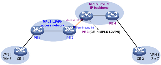
In the conventional networking mode, two devices are required to connect the MPLS L2VPN and the MPLS L3VPN or IP backbone. One device terminates the MPLS L2VPN, and the other device provides access to the MPLS L3VPN or IP backbone.
As shown in Figure 1, the access network is an MPLS L2VPN. PE 1 and PE 2 are PE devices in the MPLS L2VPN. PE 1 is connected to VPN site 1. PE 2 is connected to the MPLS L3VPN/IP backbone through PE 3. PE 3 acts as a PE in the MPLS L3VPN/IP backbone and as a CE in the MPLS L2VPN at the same time.
A packet from VPN site 1 to VPN site 2 is forwarded as follows:
1. A user in VPN site 1 sends a packet to PE 1.
2. PE 1 adds an MPLS label to the packet and sends the packet through a PW to PE 2.
3. PE 2 removes the MPLS label from the packet to obtain the original Layer 2 packet, and sends the packet to the connected CE (PE 3).
4. PE 3 looks up the routing table, and forwards the packet to the destination through the MPLS L3VPN or IP backbone.
Improved L2VPN access to L3VPN or IP backbone
As shown in Figure 2, the PE Aggregation (PE-agg) device connects the MPLS L2VPN with the MPLS L3VPN or IP backbone. PE-agg terminates the MPLS L2VPN and provides access to the MPLS L3VPN or IP backbone.
Configure the PE-agg as follows so the PE-agg can implement the functions of both PE 2 and PE 3 in Figure 1:
1. Create a terminating virtual Ethernet (VE) interface on the PE-agg to terminate MPLS L2VPN packets.
This interface is referred to as the VE-L2VPN (L2VE) interface. The functions and configurations of the interface are similar to those of the terminating interface (Terminating int) in Figure 1.
2. Create an access VE interface on the PE-agg to provide access to the backbone, and configure the interface and the L2VE interface have the same interface number.
This interface is referred to as the VE-L3VPN (L3VE) interface. The functions and configurations of the interface are similar to those of the access interface (Access int) in Figure 1. The IP address of the L3VE interface must be in the same network segment as the AC interface of CE 1. When the backbone is an MPLS L3VPN, bind the VPN instance to the L3VE interface. The interface can then forward user packets through the VPN routes.
The L2VE interface directly delivers the obtained Layer 2 packets to the L3VE interface. The two VE interfaces can be considered directly connected through a physical link.
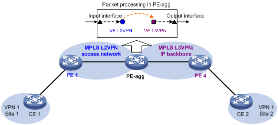
The PE-agg connects the MPLS L2VPN and the backbone through the L2VE interface and the L3VE interface. You can assume that the MPLS L2VPN is connected to the backbone through an Ethernet or VLAN link.
Restrictions: Hardware compatibility with L2VPN access to L3VPN or IP backbone
This feature is supported only on CSPC-GE16XP4L-E, CSPC-GE24L-E, CSPC-GP24GE8XP2L-E, CSPEX, and CEPC cards.
Configuring conventional L2VPN access to L3VPN or IP backbone
As shown in Figure 1, perform the following tasks to configure conventional L2VPN access to L3VPN or IP backbone:
1. Configure the MPLS L2VPN:
¡ Configure PE 1 and PE 2 as PE devices in the MPLS L2VPN.
¡ Configure CE 1 and PE 3 as CE devices in the MPLS L2VPN.
For more information about MPLS L2VPN configuration, see "Configuring MPLS L2VPN" and "Configuring VPLS."
2. Configure the MPLS L3VPN or IP backbone:
¡ Configure PE 3 and PE 4 as PE devices in the MPLS L3VPN or IP backbone.
¡ Configure CE 1 and CE 2 as CE devices in the MPLS L3VPN or IP backbone.
For more information about MPLS L3VPN configuration, see "Configuring MPLS L3VPN."
Configuring improved L2VPN access to L3VPN or IP backbone
Restrictions and guidelines
· The L2VE interface and L3VE interface created on the PE-agg must have the same interface number.
· If the access network is an MPLS L2VPN network, do not configure local connection on the PE-agg.
· When packets entering an MPLS L3VPN or IP backbone carry VLAN tags, you must create an L3VE subinterface on the L3VE interface to terminate the VLAN tags. For more information about VLAN termination, see Layer 2—LAN Switching Configuration Guide.
· If the access network is a VPLS network, follow these restrictions and guidelines when you configure local connection on the PE-agg:
¡ If the AC bound to the VSI is a Layer 3 subinterface, you can specify only one VLAN ID when you configure Dot1q or QinQ termination on the subinterface. For more information about VLAN termination, see VLAN termination configuration in Layer 2—LAN Switching Configuration Guide.
¡ If the AC bound to the VSI is an Ethernet service instance, the AC access mode cannot be Ethernet.
Procedure
Configurations required on PEs and CEs are similar to those on the devices in the conventional L2VPN access scenario. The PE-agg requires the following configurations:
1. Create an L2VE interface:
a. Enter system view.
system-view
b. Create an L2VE interface and enter its view.
interface ve-l2vpn interface-number
c. Bring up the interface.
undo shutdown
By default, the interface is up.
2. Create an L3VE interface:
a. Enter system view.
system-view
b. Create an L3VE interface or subinterface and enter its view.
interface ve-l3vpn { interface-number | interface-number.subnumber }
c. Bring up the interface.
undo shutdown
By default, the interface is up.
3. Configure MPLS L2VPN.
For more information, see "Configuring MPLS L2VPN" and "Configuring VPLS."
4. Configure MPLS L3VPN or IP routes.
For more information about MPLS L3VPN configuration, see "Configuring MPLS L3VPN."
Configuring an L2VE or L3VE interface
Configuring an L2VE interface
1. Enter system view.
system-view
2. Enter L2VE interface view.
interface ve-l2vpn interface-number
3. Configure the description of the interface.
description text
By default, the description of the interface is VE-L2VPNnumber Interface, for example, VE-L2VPN100 Interface.
Configuring an L3VE interface
Restrictions and guidelines
When you configure a MAC address for an L3VE interface, follow these restrictions and guidelines:
· You can configure a MAC address for an L3VE interface only when the system operating mode is WAN SDN. For more information about system operating modes, see device management configuration in Fundamentals Configuration Guide.
· You can configure a MAC address for an L3VE interface only when the interface resides on a CSPEX (except CSPEX-1204 and CSPEX-1104-E) or CEPC card.
· You cannot configure a MAC address for an L3VE subinterface. All subinterfaces of an L3VE interface use the MAC address of the L3VE interface.
Procedure
1. Enter system view.
system-view
2. Enter L3VE interface or subinterface view.
interface ve-l3vpn { interface-number | interface-number.subnumber }
3. Configure the description of the interface.
description text
By default, the description of the interface is VE-L3VPNnumber Interface, for example, VE-L3VPN100 Interface.
4. Set the MTU for the interface.
mtu size
By default, the MTU is 1500 bytes.
5. Configure a MAC address for the interface.
mac-address mac-address
By default, the MAC address of an L3VE interface is assigned by the device.
Restoring the default settings for an interface
Restrictions and guidelines
Restoring the default settings for an interface might interrupt ongoing network services. Make sure you are fully aware of the impact of the default command when you use it on a live network.
Procedure
1. Enter system view.
system-view
2. Enter L2VE interface view, L3VE interface view, or L3VE subinterface view.
interface interface-type { interface-number | interface-number.subnumber }
3. Restore the default settings for the interface.
default
Display and maintenance commands for L2VPN access to L3VPN or IP backbone
Execute display commands in any view and reset commands in user view.
|
Task |
Command |
|
Display information about L2VE interfaces. |
display interface [ ve-l2vpn [ interface-number ] ] [ brief [ description | down ] ] |
|
Display information about L3VE interfaces. |
display interface [ ve-l3vpn [ interface-number | interface-number.subnumber ] ] [ brief [ description | down ] ] |
|
Clear L2VE interface statistics. |
reset counters interface [ ve-l2vpn [ interface-number ] ] |
|
Clear L3VE interface statistics. |
reset counters interface [ ve-l3vpn [ interface-number | interface-number.subnumber ] ] |
Improved L2VPN access to L3VPN or IP backbone configuration examples
Example: Configuring access to MPLS L3VPN through an LDP MPLS L2VPN
The MPLS L2VPN in this configuration example is a point-to-point MPLS L2VPN.
Network configuration
The backbone is an MPLS L3VPN, which advertises VPN routes through BGP and forwards VPN packets based on MPLS labels.
CE 1 and CE 2 belong to VPN 1 whose route target is 111:1 and RD is 200:1. CE 1 is connected to PE 1 through interface GigabitEthernet 3/1/1. CE 2 is connected to the MPLS L3VPN through interface GigabitEthernet 3/1/1.
Perform the following configurations to allow communication between CE 1 and CE 2:
· Set up an LDP PW between PE 1 and PE-agg, so that CE 1 can access the MPLS L3VPN through MPLS L2VPN.
· Run EBGP between CE 1 and PE-agg and between CE 2 and PE 2 to exchange VPN routing information.
· Run MP-IBGP between PE-agg and PE 2 to exchange VPN routing information.
· Run IS-IS between PE-agg and PE 2 to ensure IP connectivity within the backbone.
· Run OSPF among PE 1, P, and PE-agg to ensure IP connectivity between the PEs.
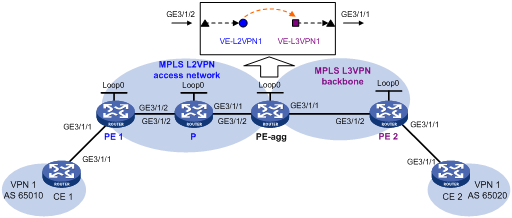
Table 1 Interface and IP address assignment
|
Device |
Interface |
IP address |
Device |
Interface |
IP address |
|
CE 1 |
GE3/1/1 |
100.1.1.1/24 |
PE-agg |
Loop0 |
3.3.3.9/32 |
|
PE 1 |
Loop0 |
1.1.1.9/32 |
|
GE3/1/2 |
10.2.2.2/24 |
|
|
GE3/1/2 |
10.2.1.1/24 |
|
GE3/1/1 |
10.3.3.1/24 |
|
P |
Loop0 |
2.2.2.9/32 |
|
VE-L3VPN1 |
100.1.1.2/24 |
|
|
GE3/1/2 |
10.2.1.2/24 |
PE 2 |
Loop0 |
4.4.4.9/32 |
|
|
GE3/1/1 |
10.2.2.1/24 |
|
GE3/1/2 |
10.3.3.2/24 |
|
CE 2 |
GE3/1/1 |
100.2.1.2/24 |
|
GE3/1/1 |
100.2.1.1/24 |
Procedure
1. Configure IP addresses for interfaces as shown in Figure 3. (Details not shown.)
2. Create VE-L2VPN 1 and VE-L3VPN 1 on PE-agg:
# Create VE-L2VPN 1.
<PEagg> system-view
[PEagg] interface ve-l2vpn 1
[PEagg-VE-L2VPN1] quit
# Create VE-L3VPN 1.
[PEagg] interface ve-l3vpn 1
[PEagg-VE-L3VPN1] quit
3. Configure MPLS L2VPN:
a. Configure OSPF on PE 1, P, and PE-agg, and advertise interface addresses:
# Configure PE 1.
<PE1> system-view
[PE1] ospf
[PE1-ospf-1] area 0
[PE1-ospf-1-area-0.0.0.0] network 1.1.1.9 0.0.0.0
[PE1-ospf-1-area-0.0.0.0] network 10.2.1.0 0.0.0.255
[PE1-ospf-1-area-0.0.0.0] quit
[PE1-ospf-1] quit
# Configure the P device.
<P> system-view
[P] ospf
[P-ospf-1] area 0
[P-ospf-1-area-0.0.0.0] network 2.2.2.9 0.0.0.0
[P-ospf-1-area-0.0.0.0] network 10.2.2.0 0.0.0.255
[P-ospf-1-area-0.0.0.0] network 10.2.1.0 0.0.0.255
[P-ospf-1-area-0.0.0.0] quit
[P-ospf-1] quit
# Configure PE-agg.
[PEagg] ospf
[PEagg-ospf-1] area 0
[PEagg-ospf-1-area-0.0.0.0] network 3.3.3.9 0.0.0.0
[PEagg-ospf-1-area-0.0.0.0] network 10.2.2.0 0.0.0.255
[PEagg-ospf-1-area-0.0.0.0] quit
[PEagg-ospf-1] quit
b. Configure basic MPLS and MPLS LDP on PE 1, P, and PE-agg:
# Configure PE 1.
[PE1] mpls lsr-id 1.1.1.9
[PE1] mpls ldp
[PE1-ldp] lsp-trigger all
[PE1-ldp] quit
[PE1] interface gigabitethernet 3/1/2
[PE1-GigabitEthernet3/1/2] mpls enable
[PE1-GigabitEthernet3/1/2] mpls ldp enable
[PE1-GigabitEthernet3/1/2] quit
# Configure the P device.
[P] mpls lsr-id 2.2.2.9
[P] mpls ldp
[P-ldp] lsp-trigger all
[P-ldp] quit
[P] interface gigabitethernet 3/1/2
[P-GigabitEthernet3/1/2] mpls enable
[P-GigabitEthernet3/1/2] mpls ldp enable
[P-GigabitEthernet3/1/2] quit
[P] interface gigabitethernet 3/1/1
[P-GigabitEthernet3/1/1] mpls enable
[P-GigabitEthernet3/1/1] mpls ldp enable
[P-GigabitEthernet3/1/1] quit
# Configure PE-agg.
[PEagg] mpls lsr-id 3.3.3.9
[PEagg] mpls ldp
[PEagg-ldp] lsp-trigger all
[PEagg-ldp] quit
[PEagg] interface gigabitethernet 3/1/2
[PEagg-GigabitEthernet3/1/2] mpls enable
[PEagg-GigabitEthernet3/1/2] mpls ldp enable
[PEagg-GigabitEthernet3/1/2] quit
c. Enable L2VPN on PE 1 and PE-agg:
# Configure PE 1.
[PE1] l2vpn enable
# Configure PE-agg.
[PEagg] l2vpn enable
d. Configure the AC interfaces of PE 1 and PE-agg, create PWs, and bind the interface to the PWs:
# On PE 1, create cross-connect group 1, create cross-connect 1 in the group, and bind GigabitEthernet 3/1/1 to the cross-connect.
[PE1] xconnect-group 1
[PE1-xcg-1] connection 1
[PE1-xcg-1-1] ac interface gigabitethernet3/1/1
[PE1-xcg-1-1] peer 3.3.3.9 pw-id 101
[PE1-xcg-1-1-3.3.3.9-101] quit
# On PE-agg, create cross-connect group 1, create cross-connect 1 in the group, and bind VE-L2VPN 1 to the cross-connect.
[PEagg] xconnect-group 1
[PEagg-xcg-1] connection 1
[PEagg-xcg-1-1] ac interface ve-l2vpn 1
[PEagg-xcg-1-1] peer 1.1.1.9 pw-id 101
[PEagg-xcg-1-1-1.1.1.9-101] quit
4. Configure MPLS L3VPN:
a. Configure IS-IS on PE 2 and PE-agg, and advertise interface addresses:
# Configure PE-agg.
[PEagg] isis 1
[PEagg-isis-1] network-entity 10.0000.0000.0001.00
[PEagg-isis-1] quit
[PEagg] interface gigabitethernet 3/1/1
[PEagg-GigabitEthernet3/1/1] isis enable 1
[PEagg-GigabitEthernet3/1/1] quit
[PEagg] interface loopback 0
[PEagg-LoopBack0] isis enable 1
[PEagg-LoopBack0] quit
# Configure PE 2.
[PE2] isis 1
[PE2-isis-1] network-entity 10.0000.0000.0002.00
[PE2-isis-1] quit
[PE2] interface gigabitethernet 3/1/2
[PE2-GigabitEthernet3/1/2] isis enable 1
[PE2-GigabitEthernet3/1/2] quit
[PE2] interface loopback 0
[PE2-LoopBack0] isis enable 1
[PE2-LoopBack0] quit
b. Configure basic MPLS and MPLS LDP on PE-agg and PE 2:
# Configure PE-agg.
[PEagg] interface gigabitethernet 3/1/1
[PEagg-GigabitEthernet3/1/1] mpls enable
[PEagg-GigabitEthernet3/1/1] mpls ldp enable
[PEagg-GigabitEthernet3/1/1] quit
# Configure PE 2.
[PE2] mpls lsr-id 4.4.4.9
[PE2] mpls ldp
[PE2-ldp] lsp-trigger all
[PE2-ldp] quit
[PE2] interface gigabitethernet 3/1/2
[PE2-gigabitethernet 3/1/2] mpls enable
[PE2-gigabitethernet 3/1/2] mpls ldp enable
[PE2-gigabitethernet 3/1/2] quit
c. On PE-agg and PE 2, create VPN instance VPN1, and bind the VPN instance to the interface connected to the CE:
# Configure PE-agg.
[PEagg] ip vpn-instance VPN1
[PEagg-vpn-instance-VPN1] route-distinguisher 200:1
[PEagg-vpn-instance-VPN1] vpn-target 111:1 both
[PEagg-vpn-instance-VPN1] quit
[PEagg] interface ve-l3vpn 1
[PEagg-VE-L3VPN1] ip binding vpn-instance VPN1
[PEagg-VE-L3VPN1] ip address 100.1.1.2 24
# Configure PE 2.
[PE2] ip vpn-instance VPN1
[PE2-vpn-instance-VPN1] route-distinguisher 200:1
[PE2-vpn-instance-VPN1] vpn-target 111:1 both
[PE2-vpn-instance-VPN1] quit
[PE2] interface gigabitethernet 3/1/1
[PE2-GigabitEthernet3/1/1] ip binding vpn-instance VPN1
[PE2-GigabitEthernet3/1/1] ip address 100.2.1.1 24
[PE2-GigabitEthernet3/1/1] quit
d. Establish EBGP peer relationships between CE 1 and PE-agg, and between CE 2 and PE 2 to redistribute VPN routes:
# Configure CE 1 and specify PE-agg as the peer.
<CE1> system-view
[CE1] bgp 65010
[CE1-bgp] peer 100.1.1.2 as-number 100
[CE1-bgp] address-family ipv4
[CE1-bgp-ipv4] peer 100.1.1.2 enable
[CE1-bgp-ipv4] import-route direct
[CE1-bgp-ipv4] quit
[CE1-bgp] quit
# Configure PE-agg and specify CE 1 as the peer.
[PEagg] bgp 100
[PEagg-bgp] ip vpn-instance VPN1
[PEagg-bgp-VPN1] peer 100.1.1.1 as-number 65010
[PEagg-bgp-VPN1] address-family ipv4
[PEagg-bgp-ipv4-VPN1] peer 100.1.1.1 enable
[PEagg-bgp-ipv4-VPN1] import-route direct
[PEagg-bgp-ipv4-VPN1] quit
[PEagg-bgp-VPN1] quit
[PEagg-bgp] quit
# Configure CE 2 and specify PE 2 as the peer.
[CE2] bgp 65020
[CE2-bgp] peer 100.2.1.1 as-number 100
[CE2-bgp] address-family ipv4
[CE2-bgp-ipv4] peer 100.2.1.1 enable
[CE2-bgp-ipv4] import-route direct
[CE2-bgp-ipv4] quit
[CE2-bgp] quit
# Configure PE 2 and specify CE 2 as the peer.
[PE2] bgp 100
[PE2-bgp] ip vpn-instance VPN1
[PE2-bgp-VPN1] peer 100.2.1.2 as-number 65020
[PE2-bgp-VPN1] address-family ipv4
[PE2-bgp-ipv4-VPN1] peer 100.2.1.2 enable
[PE2-bgp-ipv4-VPN1] import-route direct
[PE2-bgp-ipv4-VPN1] quit
[PE2-bgp-VPN1] quit
[PE2-bgp] quit
e. Establish an MP-IBGP peer relationship between PE-agg and PE 2:
# Configure PE-agg.
[PEagg] bgp 100
[PEagg-bgp] peer 4.4.4.9 as-number 100
[PEagg-bgp] peer 4.4.4.9 connect-interface loopback 0
[PEagg-bgp] address-family vpnv4
[PEagg-bgp-vpnv4] peer 4.4.4.9 enable
[PEagg-bgp-vpnv4] quit
[PEagg-bgp] quit
# Configure PE 2.
[PE2] bgp 100
[PE2-bgp] peer 3.3.3.9 as-number 100
[PE2-bgp] peer 3.3.3.9 connect-interface loopback 0
[PE2-bgp] address-family vpnv4
[PE2-bgp-vpnv4] peer 3.3.3.9 enable
[PE2-bgp-vpnv4] quit
[PE2-bgp] quit
5. The default MTU value varies by interface type. To avoid packet fragmentation, set the MTU value for each GE interface on each device to 1500 bytes. The following shows the MTU configuration on PE 1.
[PE1] interface gigabitethernet3/1/2
[PE1-GigabitEthernet3/1/2] mtu 1500
[PE1-GigabitEthernet3/1/2] shutdown
[PE1-GigabitEthernet3/1/2] undo shutdown
Verifying the configuration
# Ping CE 2 from CE 1 to verify their connectivity.
<CE1> ping 100.2.1.2
Ping 100.2.1.2 (100.2.1.2): 56 data bytes, press CTRL_C to break
56 bytes from 100.2.1.2: icmp_seq=0 ttl=128 time=1.073 ms
56 bytes from 100.2.1.2: icmp_seq=1 ttl=128 time=1.428 ms
56 bytes from 100.2.1.2: icmp_seq=2 ttl=128 time=19.367 ms
56 bytes from 100.2.1.2: icmp_seq=3 ttl=128 time=1.013 ms
56 bytes from 100.2.1.2: icmp_seq=4 ttl=128 time=0.684 ms
--- Ping statistics for 100.2.1.2 ---
5 packet(s) transmitted, 5 packet(s) received, 0.0% packet loss
round-trip min/avg/max/std-dev = 0.684/4.713/19.367/7.331 ms
Example: Configuring access to IP backbone through an LDP VPLS
Network configuration
Create an LDP PW between PE 1 and PE-agg on the VPLS access network, so that CE 1 can access the IP backbone through the PW.
Configure OSPF process 2 to advertise routing information on the IP backbone.
Figure 4 Network diagram
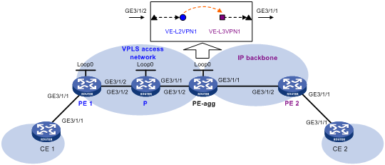
Table 2 Interface and IP address assignment
|
Device |
Interface |
IP address |
Device |
Interface |
IP address |
|
CE 1 |
GE3/1/1 |
100.1.1.1/24 |
PE-agg |
Loop0 |
3.3.3.9/32 |
|
PE 1 |
Loop0 |
1.1.1.9/32 |
|
GE3/1/2 |
10.2.2.2/24 |
|
|
GE3/1/2 |
10.2.1.1/24 |
|
GE3/1/1 |
10.3.3.1/24 |
|
P |
Loop0 |
2.2.2.9/32 |
|
VE-L3VPN1 |
100.1.1.2/24 |
|
|
GE3/1/2 |
10.2.1.2/24 |
PE 2 |
GE3/1/2 |
10.3.3.2/24 |
|
|
GE3/1/1 |
10.2.2.1/24 |
|
GE3/1/1 |
100.2.1.1/24 |
|
CE 2 |
GE3/1/1 |
100.2.1.2/24 |
|
|
|
Procedure
1. Configure IP addresses for interfaces as shown in Table 2. (Details not shown.)
2. Create VE-L2VPN 1 and VE-L3VPN 1 on PE-agg:
# Create VE-L2VPN 1.
<PEagg> system-view
[PEagg] interface ve-l2vpn 1
[PEagg-VE-L2VPN1] quit
# Create VE-L3VPN 1, and configure an IP address for the interface.
[PEagg] interface ve-l3vpn 1
[PEagg-VE-L3VPN1] ip address 100.1.1.2 24
[PEagg-VE-L3VPN1] quit
3. Configure MPLS L2VPN:
a. Configure OSPF on PE 1, P, and PE-agg, and advertise interface addresses:
# Configure PE 1.
<PE1> system-view
[PE1] ospf
[PE1-ospf-1] area 0
[PE1-ospf-1-area-0.0.0.0] network 1.1.1.9 0.0.0.0
[PE1-ospf-1-area-0.0.0.0] network 10.2.1.0 0.0.0.255
[PE1-ospf-1-area-0.0.0.0] quit
[PE1-ospf-1] quit
# Configure the P device.
<P> system-view
[P] ospf
[P-ospf-1] area 0
[P-ospf-1-area-0.0.0.0] network 2.2.2.9 0.0.0.0
[P-ospf-1-area-0.0.0.0] network 10.2.2.0 0.0.0.255
[P-ospf-1-area-0.0.0.0] network 10.2.1.0 0.0.0.255
[P-ospf-1-area-0.0.0.0] quit
[P-ospf-1] quit
# Configure PE-agg.
[PEagg] ospf
[PEagg-ospf-1] area 0
[PEagg-ospf-1-area-0.0.0.0] network 3.3.3.9 0.0.0.0
[PEagg-ospf-1-area-0.0.0.0] network 10.2.2.0 0.0.0.255
[PEagg-ospf-1-area-0.0.0.0] quit
[PEagg-ospf-1] quit
b. Configure basic MPLS and MPLS LDP on PE 1, P, and PE-agg:
# Configure PE 1.
[PE1] mpls lsr-id 1.1.1.9
[PE1] mpls ldp
[PE1-ldp] lsp-trigger all
[PE1-ldp] quit
[PE1] interface gigabitethernet3/1/2
[PE1-GigabitEthernet3/1/2] mpls enable
[PE1-GigabitEthernet3/1/2] mpls ldp enable
[PE1-GigabitEthernet3/1/2] quit
# Configure the P device.
[P] mpls lsr-id 2.2.2.9
[P] mpls ldp
[P-ldp] lsp-trigger all
[P-ldp] quit
[P] interface gigabitethernet3/1/2
[P-GigabitEthernet3/1/2] mpls enable
[P-GigabitEthernet3/1/2] mpls ldp enable
[P-GigabitEthernet3/1/2] quit
[P] interface gigabitethernet3/1/1
[P-GigabitEthernet3/1/1] mpls enable
[P-GigabitEthernet3/1/1] mpls ldp enable
[P-GigabitEthernet3/1/1] quit
# Configure PE-agg.
[PEagg] mpls lsr-id 3.3.3.9
[PEagg] mpls ldp
[PEagg-ldp] lsp-trigger all
[PEagg-ldp] quit
[PEagg] interface gigabitethernet3/1/2
[PEagg-GigabitEthernet3/1/2] mpls enable
[PEagg-GigabitEthernet3/1/2] mpls ldp enable
[PEagg-GigabitEthernet3/1/2] quit
c. Enable L2VPN on PE 1 and PE-agg:
# Configure PE 1.
[PE1] l2vpn enable
# Configure PE-agg.
[PEagg] l2vpn enable
d. Create VSIs on PE 1 and PE-agg:
# On PE 1, create VSI vpna, and specify the PW signaling protocol for the VSI as LDP.
[PE1] vsi vpna
[PE1-vsi-vpna] pwsignaling ldp
# On PE 1, create LDP PW 500 to the peer PE 3.3.3.9.
[PE1-vsi-vpna-ldp] peer 3.3.3.9 pw-id 500
[PE1-vsi-vpna-ldp-3.3.3.9-500] quit
[PE1-vsi-vpna-ldp] quit
[PE1-vsi-vpna] quit
# On PE-agg, create VSI vpna, and specify the PW signaling protocol for the VSI as LDP.
[PEagg] vsi vpna
[PEagg-vsi-vpna] pwsignaling ldp
# On PE-agg, create an LDP PW: specify the peer PE address as 1.1.1.9, and set the PW ID to 500.
[PEagg-vsi-vpna-ldp] peer 1.1.1.9 pw-id 500
[PEagg-vsi-vpna-ldp-1.1.1.9-500] quit
[PEagg-vsi-vpna-ldp] quit
[PEagg-vsi-vpna] quit
e. Bind the AC interface to the VSI on PE 1 and PE-agg:
# On PE 1, bind GigabitEthernet 3/1/1 to VSI vpna.
[PE1] interface gigabitethernet 3/1/1
[PE1-GigabitEthernet3/1/1] xconnect vsi vpna
[PE1-GigabitEthernet3/1/1] quit
# On PE-agg, bind VE-L2VPN 1 to VSI vpna.
[PEagg] interface ve-l2vpn 1
[PEagg-VE-L2VPN1] xconnect vsi vpna
[PEagg-VE-L2VPN1] quit
4. Configure OSPF process 2 to advertise routing information on the IP backbone:
# Configure CE 1.
[CE1] ospf 2
[CE1-ospf-2] area 0
[CE1-ospf-2-area-0.0.0.0] network 100.1.1.0 0.0.0.255
[CE1-ospf-2-area-0.0.0.0] quit
[CE1-ospf-2] quit
# Configure PE-agg.
[PEagg] ospf 2
[PEagg-ospf-2] area 0
[PEagg-ospf-2-area-0.0.0.0] network 100.1.1.0 0.0.0.255
[PEagg-ospf-2-area-0.0.0.0] network 10.3.3.0 0.0.0.255
[PEagg-ospf-2-area-0.0.0.0] quit
[PEagg-ospf-2] quit
# Configure PE 2.
<PE2> system-view
[PE2] ospf 2
[PE2-ospf-2] area 0
[PE2-ospf-2-area-0.0.0.0] network 100.2.1.0 0.0.0.255
[PE2-ospf-2-area-0.0.0.0] network 10.3.3.0 0.0.0.255
[PE2-ospf-2-area-0.0.0.0] quit
[PE2-ospf-2] quit
# Configure CE 2.
<CE2> system-view
[CE2] ospf 2
[CE2-ospf-2] area 0
[CE2-ospf-2-area-0.0.0.0] network 100.2.1.0 0.0.0.255
[CE2-ospf-2-area-0.0.0.0] quit
[CE2-ospf-2] quit
5. The default MTU value varies by interface type. To avoid packet fragmentation, set the MTU value for each GE interface on each device to 1500 bytes. The following shows the MTU configuration on PE 1.
[PE1] interface gigabitethernet3/1/2
[PE1-GigabitEthernet3/1/2] mtu 1500
[PE1-GigabitEthernet3/1/2] shutdown
[PE1-GigabitEthernet3/1/2] undo shutdown
Verifying the configuration
# Ping CE 2 from CE 1 to verify their connectivity.
<CE1> ping 100.2.1.2
Ping 100.2.1.2 (100.2.1.2): 56 data bytes, press CTRL_C to break
56 bytes from 100.2.1.2: icmp_seq=0 ttl=128 time=1.073 ms
56 bytes from 100.2.1.2: icmp_seq=1 ttl=128 time=1.428 ms
56 bytes from 100.2.1.2: icmp_seq=2 ttl=128 time=19.367 ms
56 bytes from 100.2.1.2: icmp_seq=3 ttl=128 time=1.013 ms
56 bytes from 100.2.1.2: icmp_seq=4 ttl=128 time=0.684 ms
--- Ping statistics for 100.2.1.2 ---
5 packet(s) transmitted, 5 packet(s) received, 0.0% packet loss
round-trip min/avg/max/std-dev = 0.684/4.713/19.367/7.331 ms