- Table of Contents
- Related Documents
-
| Title | Size | Download |
|---|---|---|
| 03-ATM configuration | 172.73 KB |
ATM connections and ATM switching
Restrictions: Hardware compatibility with ATM
Configuring the ATM service type
Display and maintenance commands for ATM
Link state error in IPoA application
PVC state is down when ATM interface state is up
Configuring ATM
About ATM
Asynchronous Transfer Mode (ATM) is a technology based on packet transmission mode, and it also incorporates the high speed of circuit transmission mode. Due to its flexibility and support for multimedia services, ATM is regarded as a core broadband technology.
ATM cells
As defined by the ITU-T, data is encapsulated in cells in ATM. Each ATM cell is 53 bytes in length, of which the first 5 bytes contain cell header information and the last 48 bytes contain payload. The major function of the cell header is to identify virtual connection. In addition, it can be used to carry limited flow control, congestion control, and error control information.
ATM connections and ATM switching
ATM is connection-oriented, and ATM connections are logical (virtual) connections. In an ATM network, you can create logical connections called virtual paths (VPs) and virtual circuits (VCs) on physical links.
As shown in Figure 1, you can create multiple VPs on a physical link, and each VP can be demultiplexed into multiple VCs. Cells from different users are transmitted over different VPs and VCs, which are identified by virtual path identifier (VPI) and virtual channel identifier (VCI). ATM uses VPI/VCI pairs to identify virtual connections.
Figure 1 Physical link, VP, and VC
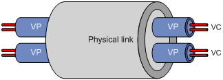
ATM interfaces support only manually created permanent virtual circuits (PVCs), not switched virtual circuits (SVCs) created through the exchange of signals. A PVC is identified by a VPI/VCI pair.
In an ATM network, an ATM switch forwards ATM cells by looking up the switching entries and changing the VPIs/VCIs. In PVC mode, the network administrator configures the switching entries and assigns VPIs/VCIs. Users can use the assigned VPIs/VCIs to configure the PVCs. If the ATM interfaces of two ATM devices are directly connected, they must be configured with the same VPIs/VCIs.
Figure 2 shows a typical ATM switching process:
1. Router A forwards a cell through PVC 0/100 on interface ATM 2/4/1.
2. ATM switch B receives the cell through PVC 0/100 on interface ATM 2/4/1.
3. ATM switch B looks up its switching entries and forwards the cell through PVC 2/101 on interface ATM 2/4/2.
4. Router C receives the cell through PVC 2/101 on interface ATM 2/4/1.

ATM architecture
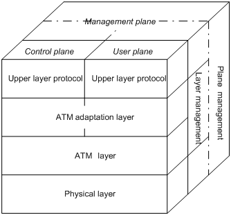
ATM has a three-dimensional architecture. It contains the user plane, control plane, and management plane.
Both the user plane and the control plane are divided into the following layers: physical layer, ATM layer, ATM Adaptation Layer (AAL), and upper layer. Each layer is further divided into sublayers.
The control plane establishes and tears down connections with signaling protocols. The management plane contains layer management and plane management. Layer management manages the layers in each plane and has a layered structure corresponding to other planes. Plane management manages the system and the communications between different planes.
Figure 3 shows the relationships between layers and planes in ATM.
ATM layers have the following functions:
· Physical layer—Provides transmission channels for ATM cells. At this layer, cells received from the ATM layer are transferred into a continuous bit stream after transmission overheads are added to them. Meanwhile, continuous bit streams received from physical media are restored to cells, which are then passed to the ATM layer.
· ATM layer—Resides over the physical layer, and implements cell-based communication with its peer layer by invoking the services provided by the physical layer. It is independent of physical media, implementation of the physical layer, and types of services being carried. AAL passes 48-byte payloads, which are called segmentation and reassembly protocol data units (SAR-PDUs) to the ATM layer. The ATM layer encapsulates the 48-byte payloads in 5-byte headers, and passes 53-byte cells to the physical layer. Other functions of the ATM layer include VPI/VCI transmission, cell multiplexing/demultiplexing, and generic flow control.
· ATM Adaptation Layer—Provides interfaces between high-level protocols and the ATM Layer. It forwards information between the ATM layer and upper-layer protocols. Four types of AAL are available: AAL1, AAL2, AAL3/4, and AAL5, each of which supports specific services provided in an ATM network. H3C uses AAL5 for data communication services.
· ATM upper-layer protocols—Responsible for WAN interconnection, Layer 3 interconnection, and IP over ATM.
ATM service types
ATM supports the following service types:
· Constant Bit Rate (CBR).
· Unspecified Bit Rate (UBR).
· Variable Bit Rate-Real Time (VBR-RT).
· Variable Bit Rate-Non Real Time (VBR-NRT).
They are used for the QoS purpose.
CBR
CBR provides ensured, constant bandwidth. The bandwidth assigned to the CBR service is decided by the Peak Cell Rate (PCR). With CBR service, a source station can send ATM cells at PCR constantly with assured QoS.
Typically, CBR is suitable for jitter-sensitive, real-time applications, such as audio and video.
VBR-RT
The VBR-RT service is provided for applications that have strict restrictions on delay and jitter, such as audio and video.
A VBR-RT connection is described by the PCR, sustainable cell rate (SCR), and maximum burst size (MBS). With the VBR-RT service, a station can send burst traffic at PCR with the maximum traffic size being MBS without cell loss and the average cell rate being SCR.
VBR-NRT
The VBR-NRT service supports non-real-time applications with burst traffic. A VBR-NRT connection is described by PCR, SCR, and MBS. The VBR-NRT service is suitable for applications sensitive to cell loss but not to delay.
UBR
The UBR service does not make any service quality commitment, guaranteeing neither cell loss ratio (CLR) nor cell delay. When traffic congestion occurs, cells of the UBR service are dropped first. The UBR service is suitable for applications with low requirements for delay and bandwidth.
ATM applications
IP over ATM (IPoA) enables ATM to carry IP packets. In an IPoA implementation, ATM acts as the data link layer protocol for the IP hosts on the same network. To enable these hosts to communicate across an ATM network, IP packets must be encapsulated in ATM cells.
By making full use of the advantages of ATM, IPoA delivers excellent network performance and mature QoS assurance.
ATM OAM
OAM has the following expansions:
· Operation and Maintenance in the ITU-T I.610 recommendation (02/99).
· Operation Administration and Maintenance in LUCENT APC User Manual (03/99).
Whichever expansion is used, OAM provides a way of detecting faults, isolating faults, and monitoring network performance without interrupting ongoing services. By inserting OAM cells, which are constructed in the standard ATM cell format, in cell streams, you can obtain specific information about the network.
ATM OAM provides the following functions:
· OAM Continuity Check—OAM CC requires that one end of the PVC must be configured as the CC cell source and the other end as the CC cell sink. If the detecting end fails to receive CC cells within 3 seconds, the state of the PVC changes to down. The PVC comes up only after CC cells are received again.
· OAM F5 Loopback—Sends OAM F5 Loopback cells at the specified interval after you enable OAM F5 Loopback transmission and retransmission detection and specify related parameters. If the sender fails to receive a response cell within the specified interval, it sends an OAM F5 Loopback cell again. The state of the PVC is updated during the Loopback detection. The PVC comes up when the specified number of successive OAM F5 Loopback cells are received. The PVC goes down when the specified number of successive OAM F5 Loopback cells are not received.
· OAM F5 end-to-end—Sends OAM F5 end-to-end cells through the specified PVC on the specified ATM interface. If no response is received within the specified period, the link might be disconnected or congested.
Restrictions: Hardware compatibility with ATM
ATM is supported only on the ATM subcards installed on the CMPE-1104 card.
ATM is supported only on the ATM subcards installed on the following cards:
· CSPEX-1304X
· CSPEX-1404X
· CSPEX-1504X
· CSPEX-1104-E
ATM tasks at a glance
To configure ATM, perform the following tasks:
1. Configuring an ATM interface
For information about ATM interface configuration, see Interface Configuration Guide.
3. Configuring the ATM service type
5. (Optional.) Configuring ATM OAM functions
Configuring a PVC
Restrictions and guidelines
In PVC mode, the network administrator configures the switching entries and assigns VPI/VCI values. You can configure the PVCs by using the assigned VPI/VCI values. If the ATM interfaces of two ATM devices are directly connected, you must configure the same VPI/VCI values for the interfaces.
Procedure
1. Enter system view.
system-view
2. Enter ATM interface view or ATM subinterface view.
interface atm { interface-number | interface-number.subnumber }
3. Create a PVC and enter PVC view.
pvc { pvc-name [ vpi/vci ] | vpi/vci }
4. Bring up the PVC.
undo shutdown
By default, the PVC is up.
Configuring the ATM service type
About ATM service types
ATM supports the following service types: CBR, UBR, VBR-RT, and VBR-NRT. You can configure service types for PVCs.
Procedure
1. Enter system view.
system-view
2. Enter ATM interface view or ATM subinterface view.
interface atm { interface-number | interface-number.subnumber }
3. Enter PVC view.
pvc { pvc-name [ vpi/vci ] | vpi/vci }
4. Configure the service type and related parameters for the PVC.
? Set the service type to CBR and configure related parameters.
service cbr output-pcr [ cdvt cdvt-value ]
? Set the service type to UBR and configure related parameters.
service ubr output-pcr
? Set the service type to VBR-NRT and configure related parameters.
service vbr-nrt output-pcr output-scr output-mbs
? Set the service type to VBR-RT and configure related parameters.
service vbr-rt output-pcr output-scr output-mbs
The default service type is UBR.
The newly configured service type overwrites the existing ones. You can configure different service types for different PVCs of an interface.
Configuring IPoA
About IP mappings
To enable the upper-layer protocols to find a remote device by its IP address, map the IP address of the remote device to the local PVC.
To configure an IP mapping, use one of the following methods:
· Static IP address mapping—Maps the IP address of the remote interface to the PVC.
· Default mapping—If a packet cannot find the mapping for the next hop address, the packet is transmitted through the PVC configured with the default mapping.
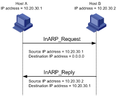
· InARP mapping—Uses Inverse Address Resolution Protocol (InARP) to resolve the IP address of the remote interface that is connected to the local PVC. You do not need to configure a static IP address for the PVC. Figure 4 shows the InARP working process. The IP addresses are the IP addresses of the ATM interfaces to which the PVC belongs.
Figure 4 InARP working process
Restrictions and guidelines
A PVC can be configured with only one IP address mapping, that is, the static IP address mapping, default mapping, or InARP mapping.
Different PVCs on the same interface cannot be mapped to the same IP address.
The PVCs on the same interface can be configured with only one default mapping.
If the interfaces of two routers are connected back-to-back, the local PVC mapped to the remote IP address must have the same VPI/VCI value as the remote PVC mapped to the local IP address.
Procedure
1. Enter system view.
system-view
2. Enter ATM interface view or ATM subinterface view.
interface atm { interface-number | interface-number.subnumber }
3. Enter PVC view.
pvc { pvc-name [ vpi/vci ] | vpi/vci }
4. Configure an IPoA mapping to enable the PVC to carry IP packets.
map ip { ip-address | default | inarp [ minutes ] }
By default, no mappings are configured for a PVC.
5. Enable the broadcast attribute for the PVC.
broadcast
By default, the broadcast attribute is disabled.
On an ATM interface, multicast or broadcast packets are sent through all PVCs that have the broadcast attribute enabled.
You must configure this command on a PVC where broadcast or multicast packets must be sent.
Configuring ATM OAM functions
Enabling ATM OAM functions
1. Enter system view.
system-view
2. Enter ATM interface view or ATM subinterface view.
interface atm { interface-number | interface-number.subnumber }
3. Enter PVC view.
pvc { pvc-name [ vpi/vci ] | vpi/vci }
4. Enable OAM F5 Loopback transmission and retransmission detection.
oam loopback interval [ up up-count down down-count retry retries ]
By default, OAM F5 Loopback cell transmission is disabled. Responses are sent if an OAM F5 Loopback cell is received.
5. Enable OAM CC.
oam cc { both | sink | source }
By default, OAM CC is disabled.
When you configure OAM CC, configure one end as source, and the other end as sink.
Checking the link connection
Send OAM F5 end-to-end cells to check the link connection.
oam ping interface atm { interface-number | interface-number.subnumber } pvc { pvc-name | vpi/vci } [ number timeout ]
This command is available in any view.
Display and maintenance commands for ATM
Execute display commands in any view and reset commands in user view.
|
Task |
Command |
|
Display PVC information. |
display atm pvc-info [ interface interface-type { interface-number | interface-number.subnumber } [ pvc { pvc-name | vpi/vci } ] ] |
|
Display mapping information about PVCs. |
display atm map-info [ interface interface-type { interface-number | interface-number.subnumber } [ pvc { pvc-name | vpi/vci } ] ] |
|
Clear PVC statistics. |
reset atm interface [ interface-type { interface-number | interface-number.subnumber } ] |
ATM configuration examples
Example: Configuring IPoA
Network configuration
As shown in Figure 5, Router A, B, and C are connected to the ATM network for intercommunication.
The IP addresses of the ATM interfaces of the three routers are 202.38.160.1/24, 202.38.160.2/24, and 202.38.160.3/24.
In the ATM network:
· The VPIs/VCIs of Router A are 0/40 and 0/41, connected to Router B and Router C, respectively.
· The VPIs/VCs of Router B are 0/50 and 0/51, connected to Router A and Router C, respectively.
· The VPIs/VCIs of Router C are 0/60 and 0/61, connected to Router A and Router B, respectively.
All the PVCs on ATM interfaces of the three routers operate in IPoA application mode.

Procedure
1. Configure Router A:
# Enter the view of interface ATM 2/4/1 and configure an IP address for it.
<RouterA> system-view
[RouterA] interface atm 2/4/1
[RouterA-ATM2/4/1] ip address 202.38.160.1 255.255.255.0
# Create PVCs, and enable them to carry IP.
[RouterA-ATM2/4/1] pvc to_b 0/40
[RouterA-ATM2/4/1-pvc-to_b-0/40] map ip 202.38.160.2
[RouterA-ATM2/4/1-pvc-to_b-0/40] quit
[RouterA-ATM2/4/1] pvc to_c 0/41
[RouterA-ATM2/4/1-pvc-to_c-0/41] map ip 202.38.160.3
2. Configure Router B:
# Enter the view of interface ATM 2/4/1 and configure an IP address for it.
<RouterB> system-view
[RouterB] interface atm 2/4/1
[RouterB-ATM2/4/1] ip address 202.38.160.2 255.255.255.0
# Create PVCs, and enable them to carry IP.
[RouterB-ATM2/4/1] pvc to_a 0/50
[RouterB-ATM2/4/1-pvc-to_a-0/50] map ip 202.38.160.1
[RouterB-ATM2/4/1-pvc-to_a-0/50] quit
[RouterB-ATM2/4/1] pvc to_c 0/51
[RouterB-ATM2/4/1-pvc-to_c-0/51] map ip 202.38.160.3
3. Configure Router C:
# Enter the view of interface ATM 2/4/1 and configure an IP address for it.
<RouterC> system-view
[RouterC] interface atm 2/4/1
[RouterC-ATM2/4/1] ip address 202.38.160.3 255.255.255.0
# Create PVCs, and enable them to carry IP.
[RouterC-ATM2/4/1] pvc to_a 0/60
[RouterC-ATM2/4/1-pvc-to_a-0/60] map ip 202.38.160.1
[RouterC-ATM2/4/1-pvc-to_a-0/60] quit
[RouterC-ATM2/4/1] pvc to_b 0/61
[RouterC-ATM2/4/1-pvc-to_b-0/61] map ip 202.38.160.2
Verifying the configuration
# Use the ping command to verify that the three routers can ping each other successfully. (Details not shown.)
Troubleshooting ATM
Link state error in IPoA application
Symptom
When IPoA is used, the link state is down.
Solution
· Verify that the optical fiber is connected correctly.
· Verify that the local IP address is configured.
· Verify that the PVC is successfully created.
Ping failure
Symptom
The physical layer of the interfaces and the line protocol are both up, but they cannot ping each other.
Solution
· If IPoA is used, make sure the IP protocol address mapping is configured correctly. If the interfaces of two routers are connected back-to-back, the local PVC mapped to the remote IP address must have the same VPI/VCI value as the remote PVC mapped to the local IP address.
· If two routers are connected back-to-back, make sure at least one of interfaces uses internal transmission clock (master). If the routers are connected to the ATM network, the transmission clock must be set to line clock (slave).
· Verify that the ATM interfaces of the two sides are of the same type. For example, both sides use multi-mode fiber interfaces, single-mode fiber interfaces, or multi-mode fiber interfaces but connected using single-mode fiber. If a multi-mode fiber interface and a single-mode fiber interface are directly connected, they can communicate in most cases, but sometimes with frequent packet dropping and CRC errors.
· If the output from the ping command shows that only small packets can pass, check the MTU settings of both router interfaces.
PVC state is down when ATM interface state is up
Symptom
The state of the ATM interface is up, but the PVC state is down.
Solution
Determine if this fault results from enabling OAM F5 Loopback cell transmission and retransmission detection or OAM continuity check. When two routers are connected, the VPI/VCI values of the PVCs on the two routers must be the same. If OAM F5 cell transmission and retransmission detection or OAM continuity check is enabled, and the VPI/VCI values of the two directly connected nodes are not the same, the local PVC state cannot change to up.