- Table of Contents
-
- 04-Layer 2 - LAN Switching Configuration Guide
- 00-Preface
- 01-MAC address table configuration
- 02-Ethernet link aggregation configuration
- 03-Port isolation configuration
- 04-VLAN configuration
- 05-MVRP configuration
- 06-QinQ configuration
- 07-VLAN mapping configuration
- 08-VLAN termination configuration
- 09-Spanning tree configuration
- 10-LLDP configuration
- 11-Service loopback group configuration
- 12-Loop detection configuration
- Related Documents
-
| Title | Size | Download |
|---|---|---|
| 08-VLAN termination configuration | 343.61 KB |
Common VLAN termination and user VLAN termination
VLAN termination application scenarios
Restrictions and guidelines: VLAN termination configuration
VLAN termination tasks at a glance
Configuring ambiguous Dot1q termination
Configuring unambiguous Dot1q termination
Configuring ambiguous QinQ termination
About ambiguous QinQ termination
Configuring ambiguous QinQ termination by specifying the outermost two layers of VLAN ID ranges
Configuring ambiguous QinQ termination by specifying the Layer 2 VLAN IDs
Configuring unambiguous QinQ termination
About unambiguous QinQ termination
Configuring common unambiguous QinQ termination by specifying the outermost two layers of VLAN IDs
Configuring unambiguous QinQ termination by specifying the Layer 2 VLAN ID
Enabling a VLAN termination-enabled interface to transmit broadcasts and multicasts
Enabling user mode of VLAN termination
Configuring the TPID for VLAN-tagged packets
Display and maintenance commands for VLAN termination
VLAN termination configuration examples
Example: Configuring ambiguous Dot1q termination
Example: Configuring unambiguous Dot1q termination
Example: Configuring Dot1q termination for PPPoE server
Example: Configuring ambiguous QinQ termination
Example: Configuring unambiguous QinQ termination
Example: Configuring QinQ termination for PPPoE server (common VLAN termination)
Example: Configuring QinQ termination for PPPoE server (user VLAN termination)
Configuring VLAN termination
About VLAN termination
VLAN termination typically processes packets that include VLAN tags. A VLAN termination-enabled interface performs the following tasks when receiving a VLAN-tagged packet:
1. Assigns the packet to an interface according to its VLAN tags.
2. Removes the VLAN tags of the packet.
3. Delivers the packet to Layer 3 forwarding or other processing pipelines.
Before sending the packet, the VLAN termination-enabled interface determines whether to add new VLAN tags to the packet, based on the VLAN termination type.
VLAN termination can also process packets that do not include any VLAN tags.
This document uses the following VLAN tag concepts for a packet that has two or more layers of VLAN tags:
· Layer 1 VLAN tag—Specifies the outermost layer of VLAN tags.
· Layer 2 VLAN tag—Specifies the second outermost layer of VLAN tags.
The VLAN IDs of the packets are numbered in the same manner as the VLAN tags.
VLAN termination types
|
Types of packets to be terminated on the interface |
Tags of outgoing packets on the interface |
|
|
Dot1q termination |
The packets must meet both of the following requirements: · The packets include one or more layers of VLAN tags. · The outermost VLAN ID matches the configured value. |
Single-tagged |
|
QinQ termination |
The packets must meet both of the following requirements: · The packets include two or more layers of VLAN tags. · The outermost two layers of tags match the configured values. |
Double-tagged |
Common VLAN termination and user VLAN termination
Depending on creation methods of VLAN termination entries, Dot1q termination and QinQ termination on a subinterface can be implemented as follows:
· Common VLAN termination—Includes common Dot1q termination and common QinQ termination, which are configured by using the vlan-type dot1q vid and vlan-type dot1q vid second-dot1q commands, respectively. The device immediately creates entries to record VLAN termination information when these commands are executed.
· User VLAN termination—Includes user VLAN Dot1q termination and user VLAN QinQ termination, which are configured by using the user-vlan dot1q vid and user-vlan dot1q vid second-dot1q commands, respectively. The device dynamically creates entries for online users in the specified VLANs to save system resources.
User VLAN termination applies to user access scenarios with BRAS devices, for example, IPoE or PPPoE networks. The mechanism of user VLAN termination is similar to common VLAN termination.
Common VLAN termination and user VLAN termination cannot be configured on the same subinterface.
Unless otherwise specified, Dot1q termination and QinQ termination in this document are implemented in the common way.
VLAN termination mechanism
VLAN interfaces and subinterfaces, such as Layer 3 Ethernet subinterfaces and Layer 3 aggregate subinterfaces, can terminate the following packets:
· Packets whose outermost VLAN IDs match the configured values.
· Packets whose outermost two layers of VLAN IDs match the configured values.
A VLAN interface terminates only the packets whose outermost VLAN ID is the same as the VLAN interface number. For example, VLAN-interface 10 terminates only the packets with the outermost VLAN tag 10.
A main interface does not terminate VLAN-tagged packets (for example, Layer 3 Ethernet interface or Layer 3 aggregate interface). To terminate VLAN-tagged packets, create subinterfaces for the main interface.
Subinterfaces of the same main interface can use different types of VLAN termination. To process received packets, the system selects a subinterface based on the following VLAN termination types in descending order of priority:
· QinQ termination.
· Dot1q termination or support for Dot1q termination by default.
If none of these VLAN termination types applies, the main interface processes the packets.
When a main interface is bound to a VLAN interface, the main interface processes VLAN-tagged packets according to the VLAN termination configuration of the VLAN interface.
VLAN termination application scenarios
Inter-VLAN communication
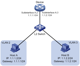
Hosts in different VLANs cannot directly communicate with each other. You can use Layer 3 routing to allow all VLANs to communicate. To restrict communication to the specified VLANs, configure VLAN termination on subinterfaces or VLAN interfaces.
As shown in Figure 1, Host A and Host B are in different VLANs. For the two hosts to communicate with each other, perform the following tasks:
1. Specify 1.1.1.1/24 and 1.1.2.1/24 as the gateway IP address for Host A and Host B, respectively.
2. On the device, configure Dot1q termination on Layer 3 Ethernet subinterfaces Subinterface A.2 and Subinterface A.3.
Figure 1 Inter-VLAN communication through Layer 3 subinterfaces
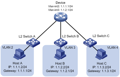
As shown in Figure 2, Host A is in VLAN 2, Host B is in VLAN 3, and Host C is in VLAN 4. For Host A and Host B to communicate with each other, perform the following tasks:
1. Specify 1.1.1.1/24 and 1.1.2.1/24 as the gateway IP address for Host A and Host B, respectively.
2. On the device, create VLAN-interface 2 and configure the IP address as 1.1.1.1/24, which is the same as the gateway address of Host A. Create VLAN-interface 3 and configure the IP address as 1.1.2.1/24, which is the same as the gateway address of Host B.
VLAN termination by the outermost VLAN ID of packets is automatically performed on VLAN interfaces. For example, when Host A sends a packet to Host B, VLAN-interface 2 removes the VLAN tag from the packet and forwards it to VLAN-interface 3. Then, VLAN-interface 3 tags the packet with VLAN 3 and Host B can receive the packet.
Because the device does not have a VLAN interface to terminate packets from VLAN 4, Host C cannot communicate with Host A or Host B.
Figure 2 Inter-VLAN communication through VLAN interfaces
LAN-WAN communication
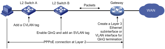
Typically, WAN protocols such as ATM and PPP do not recognize VLAN-tagged packets from LANs. Before packets are sent to a WAN, the sending port must locally record the VLAN information and remove VLAN tags from the packets. To do that, configure VLAN termination on subinterfaces or VLAN interfaces.
As shown in Figure 3, a host is located on a customer network and wants to access the WAN network through a PPPoE connection. CVLAN and SVLAN represent the VLAN on the customer network and service provider network, respectively.
To access the WAN network, a packet originating from the host is processed as follows:
1. Layer 2 Switch A adds a CVLAN tag to the packet and sends the packet.
2. Layer 2 Switch B adds an SVLAN tag to the packet on the QinQ-enabled port.
3. The packet is forwarded on the service provider network based on the SVLAN tag.
4. The gateway removes the two layers of VLAN tags from the packet and adds new VLAN tags on the QinQ termination-enabled port.
5. The gateway sends the packet to the WAN.
Figure 3 VLAN termination enables LAN-WAN communication
Restrictions and guidelines: VLAN termination configuration
When you configure VLAN termination, follow these restrictions and guidelines:
· On a portal-enabled interface, log off all portal users before you change the VLAN termination type, for example, from Dot1q termination to QinQ termination. Any portal users who remain online after the change cannot be logged off or reauthenticated. For more information about portal authentication, see BRAS Services Configuration Guide.
· After you modify the common VLAN termination configuration for a subinterface, the subinterface automatically restarts. All dynamic ARP table entries for the subinterface are deleted. To avoid this issue, configure the vlan-termination user-mode command on the subinterface. For more information, see "Enabling user mode of VLAN termination".
· The user mode of VLAN termination is always enabled on a subinterface that is configured with user VLAN termination. You cannot disable this feature.
· When QinQ termination is configured on a VLAN interface, make sure the incoming and outgoing packets on all ports of the VLAN carry a minimum of two VLAN tags. If this requirement cannot be met, packets cannot be correctly forwarded.
· As a best practice to avoid configuration conflicts, do not configure the user VLAN termination commands with any of the following commands on the same subinterface:
¡ The portal [ ipv6 ] enable command to enable portal authentication.
¡ The ip subscriber l2vpn-leased command to configure L2VPN-leased users.
¡ The ip subscriber routed enable command to enable IPoE and configure the Layer 3 access mode for IPv4 users.
· To ensure the routing stability, do not configure the two peer subinterfaces to terminate multiple Layer 1 VLAN IDs at the same time if they are running a routing protocol.
· Subinterfaces on the following interfaces do not support user VLAN termination and terminate only packets whose outermost VLAN ID is the same as the subinterface number:
¡ Layer 3 Ethernet interfaces on the CSPC cards (except CSPC-GE16XP4L-E, CSPC-GE24L-E, and CSPC-GP24GE8XP2L-E) and CMPE-1104 cards.
¡ Layer 3 aggregate interfaces that have member ports on the CSPC cards (except CSPC-GE16XP4L-E, CSPC-GE24L-E, and CSPC-GP24GE8XP2L-E) and CMPE-1104 cards.
VLAN termination tasks at a glance
To configure VLAN termination, perform the following tasks:
1. (Required.) Configuring VLAN termination
Choose one of the following tasks:
¡ Configuring ambiguous Dot1q termination
¡ Configuring unambiguous Dot1q termination
¡ Configuring ambiguous QinQ termination
¡ Configuring unambiguous QinQ termination
2. (Optional.) Enabling a VLAN termination-enabled interface to transmit broadcasts and multicasts
Perform this task to enable ambiguous Dot1q or QinQ termination-enabled interfaces to transmit broadcasts and multicasts.
3. (Optional.) Enabling user mode of VLAN termination
Perform this task to prevent subinterface restart caused by VLAN termination setting modification.
4. (Optional.) Configuring the TPID for VLAN-tagged packets
Configuring ambiguous Dot1q termination
About ambiguous Dot1q termination
Use this feature to terminate VLAN-tagged packets whose outermost VLAN IDs are in the specified range. Other VLAN-tagged packets are not allowed to pass.
When an interface receives a packet, it removes the outermost VLAN ID from the packet. When the interface sends a packet, it tags the packet with a VLAN ID as follows:
· For a PPPoE packet, the VLAN ID is from the matching PPPoE session entry.
· For a DHCP relay packet, the VLAN ID is from the matching DHCP session entry.
· For an IPv4 or MPLS packet, the VLAN ID is from the matching ARP entry.
Configuring common ambiguous Dot1q termination
1. Enter system view.
system-view
2. Enter interface view.
¡ Enter Layer 3 Ethernet subinterface view.
interface interface-type interface-number.subnumber
¡ Enter Layer 3 aggregate subinterface view.
interface route-aggregation interface-number.subnumber
¡ Enter L3VE subinterface view.
interface ve-l3vpn interface-number.subnumber
3. Configure ambiguous Dot1q termination.
vlan-type dot1q vid vlan-id-list
By default, Dot1q termination is disabled on a subinterface.
Configuring ambiguous user VLAN Dot1q termination
1. Enter system view.
system-view
2. Enter interface view.
¡ Enter Layer 3 Ethernet subinterface view.
interface interface-type interface-number.subnumber
¡ Enter Layer 3 aggregate subinterface view.
interface route-aggregation interface-number.subnumber
3. Configure ambiguous user VLAN Dot1q termination.
user-vlan dot1q vid vlan-id-list
By default, user VLAN Dot1q termination is disabled on a subinterface.
Configuring unambiguous Dot1q termination
About unambiguous Dot1q termination
Use this feature to terminate only VLAN-tagged packets whose outermost VLAN ID matches the specified VLAN ID. Other VLAN-tagged packets are not allowed to pass.
When an interface receives a packet, it removes the outermost VLAN ID from the packet. When the interface sends a packet, it tags the packet with the specified VLAN ID.
Configuring common unambiguous Dot1q termination
1. Enter system view.
system-view
2. Enter interface view.
¡ Enter Layer 3 Ethernet subinterface view.
interface interface-type interface-number.subnumber
¡ Enter Layer 3 aggregate subinterface view.
interface route-aggregation interface-number.subnumber
¡ Enter L3VE subinterface view.
interface ve-l3vpn interface-number.subnumber
3. Configure unambiguous Dot1q termination.
vlan-type dot1q vid vlan-id
By default, Dot1q termination is disabled on a subinterface.
Configuring unambiguous user VLAN Dot1q termination
1. Enter system view.
system-view
2. Enter interface view.
¡ Enter Layer 3 Ethernet subinterface view.
interface interface-type interface-number.subnumber
¡ Enter Layer 3 aggregate subinterface view.
interface route-aggregation interface-number.subnumber
3. Configure unambiguous user VLAN Dot1q termination.
user-vlan dot1q vid vlan-id
By default, user VLAN Dot1q termination is disabled on a subinterface.
Configuring ambiguous QinQ termination
About ambiguous QinQ termination
Use this feature to terminate QinQ packets whose outermost two layers of VLAN IDs are in the specified range.
When an interface receives a packet, it removes the outermost two layers of VLAN tags from the packet. When the interface sends a packet, it tags the packet with the outermost two layers of VLAN IDs, which are determined as follows:
· For a PPPoE packet, VLAN IDs are from the matching PPPoE session entry.
· For a DHCP relay packet, VLAN IDs are from the matching DHCP relay entry.
· For an IPv4 or MPLS packet, VLAN IDs are from the matching ARP entry.
Configuring ambiguous QinQ termination by specifying the outermost two layers of VLAN ID ranges
Restrictions and guidelines
· If you specify the same Layer 1 VLAN ID for multiple subinterfaces of the same main interface, specify different Layer 2 VLAN IDs for them. However, if you specify different Layer 1 VLAN IDs for the subinterfaces, the Layer 2 VLAN IDs specified for the subinterfaces are not required to be different.
· Subinterfaces of different main interfaces can terminate VLAN-tagged packets with the same Layer 1 and Layer 2 VLAN IDs.
· If you execute the vlan-type dot1q vid second-dot1q or user-vlan dot1q vid second-dot1q command multiple times, all specified pairs of Layer 1 IDs and Layer 2 IDs in each execution take effect.
Configuring common ambiguous QinQ termination
1. Enter system view.
system-view
2. Enter interface view.
¡ Enter Layer 3 Ethernet subinterface view.
interface interface-type interface-number.subnumber
¡ Enter Layer 3 aggregate subinterface view.
interface route-aggregation interface-number.subnumber
¡ Enter L3VE subinterface view.
interface ve-l3vpn interface-number.subnumber
3. Configure ambiguous QinQ termination by specifying the outermost two layers of VLAN ID ranges.
vlan-type dot1q vid vlan-id-list second-dot1q { vlan-id-list | any }
By default, QinQ termination is disabled on a subinterface.
Configuring ambiguous user VLAN QinQ termination
1. Enter system view.
system-view
2. Enter interface view.
¡ Enter Layer 3 Ethernet subinterface view.
interface interface-type interface-number.subnumber
¡ Enter Layer 3 aggregate subinterface view.
interface route-aggregation interface-number.subnumber
3. Configure ambiguous user VLAN QinQ termination by specifying the outermost two layers of VLAN ID ranges.
user-vlan dot1q vid vlan-id-list second-dot1q { vlan-id-list | any }
By default, user VLAN QinQ termination is disabled on a subinterface.
Configuring ambiguous QinQ termination by specifying the Layer 2 VLAN IDs
Restrictions and guidelines
After you enable ambiguous QinQ termination on a VLAN interface, Layer 2 Ethernet interfaces bound to the VLAN interface operate as follows:
· Process only packets that match the ambiguous QinQ termination configuration of the VLAN interface.
· Drop any other packets sent to the VLAN interface.
Procedure
1. Enter system view.
system-view
2. Enter VLAN interface view.
interface vlan-interface interface-number
3. Configure ambiguous QinQ termination by specifying the Layer 2 VLAN IDs.
second-dot1q { vlan-id-list | any }
By default, QinQ termination is disabled on a VLAN interface.
The Layer 1 VLAN ID of the VLAN-tagged packets that can be terminated by the VLAN interface is the number of the VLAN interface. This Layer 1 VLAN ID is not configurable.
Configuring unambiguous QinQ termination
About unambiguous QinQ termination
Use this feature to terminate QinQ packets whose outermost two layers of VLAN IDs match the specified values.
When an interface receives a packet, it removes the two layers of VLAN tags from the packet. When the interface sends the packet, it tags the packet with two layers of VLAN tags as specified.
Configuring common unambiguous QinQ termination by specifying the outermost two layers of VLAN IDs
1. Enter system view.
system-view
2. Enter interface view.
¡ Enter Layer 3 Ethernet subinterface view.
interface interface-type interface-number.subnumber
¡ Enter Layer 3 aggregate subinterface view.
interface route-aggregation interface-number.subnumber
¡ Enter L3VE subinterface view.
interface ve-l3vpn interface-number.subnumber
3. Configure unambiguous QinQ termination by specifying the outermost two layers of VLAN IDs.
vlan-type dot1q vid vlan-id second-dot1q vlan-id
By default, QinQ termination is disabled on a subinterface.
Configuring unambiguous user VLAN QinQ termination by specifying the outermost two layers of VLAN IDs
1. Enter system view.
system-view
2. Enter interface view.
¡ Enter Layer 3 Ethernet subinterface view.
interface interface-type interface-number.subnumber
¡ Enter Layer 3 aggregate subinterface view.
interface route-aggregation interface-number.subnumber
3. Configure unambiguous user QinQ termination by specifying the outermost two layers of VLAN IDs.
user-vlan dot1q vid vlan-id second-dot1q vlan-id
By default, user VLAN QinQ termination is disabled on a subinterface.
Configuring unambiguous QinQ termination by specifying the Layer 2 VLAN ID
Restrictions and guidelines
After you enable unambiguous QinQ termination on a VLAN interface, Layer 2 Ethernet interfaces bound to the VLAN interface operate as follows:
· Process only packets that match the unambiguous QinQ termination configuration of the VLAN interface.
· Drop any other packets sent to the VLAN interface.
Procedure
1. Enter system view.
system-view
2. Enter VLAN interface view.
interface vlan-interface interface-number
3. Configure unambiguous QinQ termination by specifying the Layer 2 VLAN ID.
second-dot1q vlan-id
By default, QinQ termination is disabled on a VLAN interface.
The Layer 1 VLAN ID of the VLAN-tagged packets that can be terminated by the VLAN interface is the number of the VLAN interface. This Layer 1 VLAN ID is not configurable.
Enabling a VLAN termination-enabled interface to transmit broadcasts and multicasts
About enabling a VLAN termination-enabled interface to transmit broadcasts and multicasts
After you configure Dot1q/ QinQ termination on an interface to terminate packets of multiple VLANs, the interface drops broadcast and multicast packets by default. Use this feature to enable the interface to transmit broadcasts and multicasts.
To transmit a broadcast or multicast packet, the interface starts a traversal over the VLAN IDs specified for Dot1q/QinQ termination. It copies the packet and tags each copy with a VLAN ID, until all VLAN IDs in the specified range are traversed. For example, when ambiguous QinQ termination is configured, both layers of VLAN ID ranges are traversed.
Restrictions and guidelines
On an IPv6 network, you must use the vlan-termination broadcast ra command to enable an ambiguous Dot1q or QinQ termination-enabled interface to transmit RA multicast packets. This command prohibits transmission of broadcast packets and other types of multicast packets, and consumes less CPU resources than the vlan-termination broadcast enable command.
As a best practice, execute the undo ipv6 nd ra halt command on an interface that is configured with the vlan-termination broadcast ra command. For more information about the ipv6 nd ra halt command, see IPv6 basic commands in Layer 3—IP Services Command Reference.
Procedure
1. Enter system view.
system-view
2. Enter interface view.
¡ Enter Layer 3 Ethernet subinterface view.
interface interface-type interface-number.subnumber
¡ Enter Layer 3 aggregate subinterface view.
interface route-aggregation interface-number.subnumber
¡ Enter L3VE subinterface view.
interface ve-l3vpn interface-number.subnumber
¡ Enter VLAN interface view.
interface vlan-interface interface-number
3. Enable the interface to transmit broadcasts and multicasts.
¡ Enable the interface to transmit broadcasts and multicasts.
vlan-termination broadcast enable
¡ Enable the interface to transmit only RA multicasts on an IPv6 network.
vlan-termination broadcast ra
By default, broadcast and multicast packets are dropped on an interface configured with Dot1q/QinQ termination to terminate packets of multiple VLANs.
Enabling user mode of VLAN termination
About user mode of VLAN termination
If user mode of VLAN termination is disabled on a subinterface, the subinterface automatically restarts after you modify its VLAN termination settings. In some networks (for example, networks using IPoE or PPPoE connections), the subinterface restart logs off online users. To prevent the subinterface restart and protect the online user state, enable user mode of VLAN termination before you modify VLAN termination on the subinterface.
Restrictions and guidelines
After you enable user mode of VLAN termination and modify VLAN termination on a subinterface, clear entries of VLANs that are no longer terminated by the subinterface. For example, use the reset arp interface command in user view to clear all ARP entries for a subinterface after you modify VLAN termination on it. If you do not clear these entries, running services might be affected. For more information about the reset arp command, see ARP commands in Layer 3—IP Services Command Reference.
Procedure
1. Enter system view.
system-view
2. Enter interface view.
¡ Enter Layer 3 Ethernet subinterface view.
interface interface-type interface-number.subnumber
¡ Enter Layer 3 aggregate subinterface view.
interface route-aggregation interface-number.subnumber
¡ Enter L3VE subinterface view.
interface ve-l3vpn interface-number.subnumber
3. Enable user mode of VLAN termination.
vlan-termination user-mode
By default, user mode of VLAN termination is disabled.
Configuring the TPID for VLAN-tagged packets
About configuring TPID for VLAN-tagged packets
TPID identifies whether or not a frame contains VLAN tags. By default, the value of 0x8100 identifies an IEEE 802.1Q-tagged frame. You can set another TPID value to identify VLAN-tagged packets.
To work with VLAN termination on a subinterface, set the TPID value in the outermost VLAN tag of packets on the main interface of the subinterface. If VLAN termination is enabled on a VLAN interface, set the TPID value in the outermost VLAN tag of packets on the same VLAN interface.
The interface processes packets as untagged packets if their outermost VLAN tag is not 0x8100 or the configured value.
When sending a packet, the interface sets the TPID value in the outermost VLAN tag to the configured value. If the packet includes two or more layers of VLAN tags, the interface sets the TPID values to 0x8100 in all VLAN tags except the outermost VLAN tag.
Restrictions and guidelines
This feature is not available on the following interfaces:
· Layer 3 Ethernet interfaces on the CSPC cards (except CSPC-GE16XP4L-E, CSPC-GE24L-E, and CSPC-GP24GE8XP2L-E) and CMPE-1104 cards.
· Layer 3 aggregate interfaces that have member ports on the CSPC cards (except CSPC-GE16XP4L-E, CSPC-GE24L-E, and CSPC-GP24GE8XP2L-E) and CMPE-1104 cards.
The main interface of a subinterface cannot modify the TPID value in the outermost VLAN tag of the ARP packets sent by the subinterface when the following conditions exist on the subinterface:
· The vlan-termination broadcast enable command is executed.
· The vlan-type dot1q vid second-dot1q or user-vlan dot1q vid second-dot1q command is executed with the any keyword.
Procedure
1. Enter system view.
system-view
2. Enter interface view.
¡ Enter Layer 3 Ethernet interface view.
interface interface-type interface-number
¡ Enter Layer 3 aggregate interface view.
interface route-aggregation interface-number
¡ Enter L3VE interface view.
interface ve-l3vpn interface-number
¡ Enter VLAN interface view.
interface vlan-interface interface-number
Configurations made in Layer 3 Ethernet interface view, Layer 3 aggregate interface view, or L3VE interface view take effect on all the subinterfaces. Configurations made in VLAN interface view take effect only on the VLAN interface.
3. Set the TPID value in the outermost VLAN tag of packets received and sent by the interface.
dot1q ethernet-type hex-value
The default setting is 0x8100.
Display and maintenance commands for VLAN termination
Execute display commands in any view.
|
Task |
Command |
|
Display user VLAN termination information. |
In standalone mode: display user-vlan interface interface-type interface-number.subnumber [ slot slot-number ] In IRF mode: display user-vlan interface interface-type interface-number.subnumber [ chassis chassis-number slot slot-number ] |
VLAN termination configuration examples
Unless otherwise specified, the configuration examples are applicable to common VLAN termination. To configure user VLAN termination, change the vlan-type keyword in VLAN termination commands to the user-vlan keyword.
Example: Configuring ambiguous Dot1q termination
Network configuration
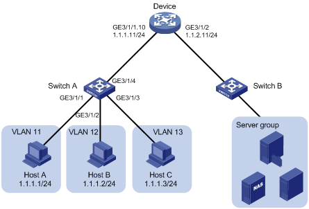
As shown in Figure 4, configure ambiguous Dot1q termination so that hosts in different VLANs can communicate with the server group.
Procedure
In this example, L2 switch B uses the factory configuration.
1. Configure Host A, Host B, and Host C:
# Assign 1.1.1.1/24, 1.1.1.2/24, and 1.1.1.3/24 to Host A, Host B, and Host C, respectively. (Details not shown.)
# Specify 1.1.1.11/24 as the gateway IP address for the hosts. (Details not shown.)
2. Configure Layer 2 Switch A:
# Create VLAN 11.
<L2_SwitchA> system-view
[L2_SwitchA] vlan 11
# Assign GigabitEthernet 3/1/1 to VLAN 11.
[L2_SwitchA-vlan11] port gigabitethernet 3/1/1
[L2_SwitchA-vlan11] quit
# Create VLAN 12.
[L2_SwitchA] vlan 12
# Assign GigabitEthernet 3/1/2 to VLAN 12.
[L2_SwitchA-vlan12] port gigabitethernet 3/1/2
[L2_SwitchA-vlan12] quit
# Create VLAN 13.
[L2_SwitchA] vlan 13
# Assign GigabitEthernet 3/1/3 to VLAN 13.
[L2_SwitchA-vlan13] port gigabitethernet 3/1/3
[L2_SwitchA-vlan13] quit
# Configure GigabitEthernet 3/1/4 as a trunk port and assign the port to VLANs 11 through 13.
[L2_SwitchA] interface gigabitethernet 3/1/4
[L2_SwitchA-GigabitEthernet3/1/4] port link-type trunk
[L2_SwitchA-GigabitEthernet3/1/4] port trunk permit vlan 11 to 13
3. Configure the device:
# Create Ethernet subinterface GigabitEthernet 3/1/1.10 and assign an IP address to the subinterface.
<Device> system-view
[Device] interface gigabitethernet 3/1/1.10
[Device-GigabitEthernet3/1/1.10] ip address 1.1.1.11 255.255.255.0
# Enable Dot1q termination on GigabitEthernet 3/1/1.10 to terminate VLAN-tagged packets whose Layer 1 VLAN IDs are 11, 12, or 13.
[Device-GigabitEthernet3/1/1.10] vlan-type dot1q vid 11 to 13
# Enable GigabitEthernet 3/1/1.10 to transmit broadcasts and multicasts.
[Device-GigabitEthernet3/1/1.10] vlan-termination broadcast enable
[Device-GigabitEthernet3/1/1.10] quit
# Configure an IP address for GigabitEthernet 3/1/2.
[Device] interface gigabitethernet 3/1/2
[Device-GigabitEthernet3/1/2] ip address 1.1.2.11 255.255.255.0
4. Configure the server group:
# Assign each device in the server group an IP address on network segment 1.1.2.0/24. (Details not shown.)
# Specify 1.1.2.11/24 as the gateway IP address for the server group. (Details not shown.)
Verifying the configuration
# Verify that Host A, Host B, and Host C can ping the device in the server group. (Details not shown.)
Example: Configuring unambiguous Dot1q termination
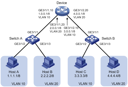
Network configuration
As shown in Figure 5, configure unambiguous Dot1q termination on subinterfaces of the device to implement intra-VLAN and inter-VLAN communications between hosts.
Procedure
1. Configure Host A, Host B, Host C, and Host D:
# On Host A, specify 1.1.1.1/8 and 1.0.0.1/8 as its IP address and gateway IP address, respectively. (Details not shown.)
# On Host B, specify 2.2.2.2/8 and 2.0.0.1/8 as its IP address and gateway IP address, respectively. (Details not shown.)
# On Host C, specify 3.3.3.3/8 and 3.0.0.1/8 as its IP address and gateway IP address, respectively. (Details not shown.)
# On Host D, specify 4.4.4.4/8 and 4.0.0.1/8 as its IP address and gateway IP address, respectively. (Details not shown.)
2. Configure Layer 2 Switch A:
# Create VLAN 10.
<L2_SwitchA> system-view
[L2_SwitchA] vlan 10
# Assign GigabitEthernet 3/1/2 to VLAN 10.
[L2_SwitchA-vlan10] port gigabitethernet 3/1/2
[L2_SwitchA-vlan10] quit
# Create VLAN 20.
[L2_SwitchA] vlan 20
# Assign GigabitEthernet 3/1/3 to VLAN 20.
[L2_SwitchA-vlan20] port gigabitethernet 3/1/3
[L2_SwitchA-vlan20] quit
# Configure GigabitEthernet 3/1/1 as a trunk port, and assign the port to VLANs 10 and 20.
[L2_SwitchA] interface gigabitethernet 3/1/1
[L2_SwitchA-GigabitEthernet3/1/1] port link-type trunk
[L2_SwitchA-GigabitEthernet3/1/1] port trunk permit vlan 10 20
3. Configure Layer 2 Switch B in the same way you configure Layer 2 Switch A. (Details not shown.)
4. Configure the device:
# Create GigabitEthernet 3/1/1.10 and assign an IP address to this interface.
<Device> system-view
[Device] interface gigabitethernet 3/1/1.10
[Device-GigabitEthernet3/1/1.10] ip address 1.0.0.1 255.0.0.0
# Configure GigabitEthernet 3/1/1.10 to terminate packets tagged with VLAN 10.
[Device-GigabitEthernet3/1/1.10] vlan-type dot1q vid 10
[Device-GigabitEthernet3/1/1.10] quit
# Create GigabitEthernet 3/1/1.20 and assign an IP address to this interface.
[Device] interface gigabitethernet 3/1/1.20
[Device-GigabitEthernet3/1/1.20] ip address 2.0.0.1 255.0.0.0
# Configure GigabitEthernet 3/1/1.20 to terminate packets tagged with VLAN 20.
[Device-GigabitEthernet3/1/1.20] vlan-type dot1q vid 20
[Device-GigabitEthernet3/1/1.20] quit
# Configure GigabitEthernet 3/1/2.10 and assign an IP address to this interface.
[Device] interface gigabitethernet 3/1/2.10
[Device-GigabitEthernet3/1/2.10] ip address 3.0.0.1 255.0.0.0
# Configure GigabitEthernet 3/1/2.10 to terminate packets tagged with VLAN 10.
[Device-GigabitEthernet3/1/2.10] vlan-type dot1q vid 10
[Device-GigabitEthernet3/1/2.10] quit
# Configure GigabitEthernet 3/1/2.20 and assign an IP address to this interface.
[Device] interface gigabitethernet 3/1/2.20
[Device-GigabitEthernet3/1/2.20] ip address 4.0.0.1 255.0.0.0
# Configure GigabitEthernet 3/1/2.20 to terminate packets tagged with VLAN 20.
[Device-GigabitEthernet3/1/2.20] vlan-type dot1q vid 20
[Device-GigabitEthernet3/1/2.20] quit
Verifying the configuration
# Verify that Host A, Host B, Host C, and Host D can ping each other. (Details not shown.)
Example: Configuring Dot1q termination for PPPoE server
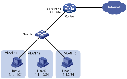
Network configuration
As shown in Figure 6, the router acts as a PPPoE server. Hosts in different VLANs access the Internet through the PPPoE server.
Configure Dot1q termination so that hosts in different VLANs can access the Internet.
Procedure
# Configure VLANs and Dot1q termination. For the configuration procedure, see "Example: Configuring ambiguous Dot1q termination." (Details not shown.)
# Configure the router as the PPPoE server. Configure PPPoE settings on GigabitEthernet 3/1/1.10 on the router. For more information about the PPPoE configuration, see BRAS Configuration Guide. (Details not shown.)
Example: Configuring ambiguous QinQ termination
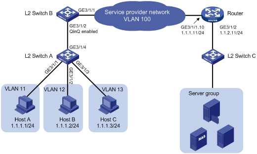
Network configuration
As shown in Figure 7, QinQ is enabled on GigabitEthernet 3/1/2 of Layer 2 Switch B.
Configure ambiguous QinQ termination, so that hosts can communicate with the server group.
Procedure
In this example, Layer 2 Switch C uses the factory configuration.
1. Configure Host A, Host B, and Host C:
# Assign the IP addresses 1.1.1.1/24, 1.1.1.2/24, and 1.1.1.3/24 to Host A, Host B, and Host C, respectively. (Details not shown.)
# Specify 1.1.1.11/24 as the gateway address for the hosts. (Details not shown.)
2. Configure Layer 2 Switch A:
# Create VLAN 11.
<L2_SwitchA> system-view
[L2_SwitchA] vlan 11
# Assign GigabitEthernet 3/1/1 to VLAN 11.
[L2_SwitchA-vlan11] port gigabitethernet 3/1/1
[L2_SwitchA-vlan11] quit
# Create VLAN 12.
[L2_SwitchA] vlan 12
# Assign GigabitEthernet 3/1/2 to VLAN 12.
[L2_SwitchA-vlan12] port gigabitethernet 3/1/2
[L2_SwitchA-vlan12] quit
# Create VLAN 13.
[L2_SwitchA] vlan 13
# Assign GigabitEthernet 3/1/3 to VLAN 13.
[L2_SwitchA-vlan13] port gigabitethernet 3/1/3
[L2_SwitchA-vlan13] quit
# Configure GigabitEthernet 3/1/4 as a trunk port, and assign the port to VLANs 11 through 13.
[L2_SwitchA] interface gigabitethernet 3/1/4
[L2_SwitchA-GigabitEthernet3/1/4] port link-type trunk
[L2_SwitchA-GigabitEthernet3/1/4] port trunk permit vlan 11 to 13
3. Configure Layer 2 Switch B:
# Configure GigabitEthernet 3/1/2 as a trunk port, and assign the port to VLAN 100.
<L2_SwitchB> system-view
[L2_SwitchB] interface gigabitethernet 3/1/2
[L2_SwitchB-GigabitEthernet3/1/2] port link-type trunk
[L2_SwitchB-GigabitEthernet3/1/2] port trunk permit vlan 100
# Set the PVID of GigabitEthernet 3/1/2 to VLAN 100.
[L2_SwitchB-GigabitEthernet3/1/2] port trunk pvid vlan 100
# Enable QinQ on GigabitEthernet 3/1/2.
[L2_SwitchB-GigabitEthernet3/1/2] qinq enable
[L2_SwitchB-GigabitEthernet3/1/2] quit
# Configure GigabitEthernet 3/1/1 as a trunk port and assign the port to VLAN 100.
[L2_SwitchB] interface gigabitethernet 3/1/1
[L2_SwitchB-GigabitEthernet3/1/1] port link-type trunk
[L2_SwitchB-GigabitEthernet3/1/1] port trunk permit vlan 100
4. Configure the router:
# Create Ethernet subinterface GigabitEthernet 3/1/1.10 and assign an IP address to the subinterface.
<Router> system-view
[Router] interface gigabitethernet 3/1/1.10
[Router-GigabitEthernet3/1/1.10] ip address 1.1.1.11 255.255.255.0
# Configure GigabitEthernet 3/1/1.10 to terminate VLAN-tagged packets whose Layer 1 VLAN ID is 100 and Layer 2 VLAN ID is 11, 12, or 13.
[Router-GigabitEthernet3/1/1.10] vlan-type dot1q vid 100 second-dot1q 11 to 13
# Enable GigabitEthernet 3/1/1.10 to transmit broadcasts and multicasts.
[Router-GigabitEthernet3/1/1.10] vlan-termination broadcast enable
[Router-GigabitEthernet3/1/1.10] quit
# Assign an IP address to GigabitEthernet 3/1/2.
[Router] interface gigabitethernet 3/1/2
[Router-GigabitEthernet3/1/2] ip address 1.1.2.11 255.255.255.0
5. Configure the server group:
# Assign each device in the server group an IP address on network segment 1.1.2.0/24. (Details not shown.)
# Specify 1.1.2.11/24 as the gateway IP address for the server group. (Details not shown.)
Verifying the configuration
# Verify that Host A, Host B, and Host C can ping the server group. (Details not shown.)
Example: Configuring unambiguous QinQ termination
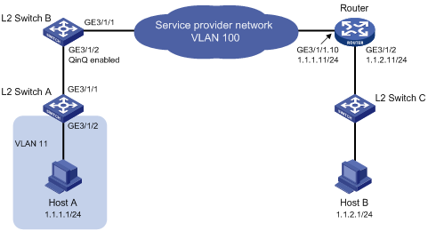
Network configuration
As shown in Figure 8:
· Layer 2 Switch C supports only single VLAN-tagged packets.
· On Layer 2 Switch B, GigabitEthernet 3/1/2 is enabled with QinQ to add an SVLAN tag 100 to the packets with CVLAN ID 11.
Configure unambiguous QinQ termination so that Host A can communicate with Host B.
Procedure
In this example, Layer 2 Switch C uses the factory configuration.
1. Configure Host A and Host B:
# On Host A, specify 1.1.1.1/24 and 1.1.1.11/24 as its IP address and gateway IP address, respectively. (Details not shown.)
# On Host B, specify 1.1.2.1/24 and 1.1.2.11/24 as its IP address and gateway IP address, respectively. (Details not shown.)
2. Configure Layer 2 Switch A:
# Create VLAN 11.
<L2_SwitchA> system-view
[L2_SwitchA] vlan 11
# Assign GigabitEthernet 3/1/2 to VLAN 11.
[L2_SwitchA-vlan11] port gigabitethernet 3/1/2
[L2_SwitchA-vlan11] quit
# Configure GigabitEthernet 3/1/1 as a trunk port and assign the port to VLAN 11.
[L2_SwitchA] interface gigabitethernet 3/1/1
[L2_SwitchA-GigabitEthernet3/1/1] port link-type trunk
[L2_SwitchA-GigabitEthernet3/1/1] port trunk permit vlan 11
3. Configure Layer 2 Switch B:
# Configure GigabitEthernet 3/1/2 as a trunk port and assign the port to VLAN 100.
<L2_SwitchB> system-view
[L2_SwitchB] interface gigabitethernet 3/1/2
[L2_SwitchB-GigabitEthernet3/1/2] port link-type trunk
[L2_SwitchB-GigabitEthernet3/1/2] port trunk permit vlan 100
# Set the PVID of GigabitEthernet 3/1/2 to VLAN 100.
[L2_SwitchB-GigabitEthernet3/1/2] port trunk pvid vlan 100
# Enable QinQ on GigabitEthernet 3/1/2.
[L2_SwitchB-GigabitEthernet3/1/2] qinq enable
[L2_SwitchB-GigabitEthernet3/1/2] quit
# Configure GigabitEthernet 3/1/1 as a trunk port and assign the port to VLAN 100.
[L2_SwitchB] interface gigabitethernet 3/1/1
[L2_SwitchB-GigabitEthernet3/1/1] port link-type trunk
[L2_SwitchB-GigabitEthernet3/1/1] port trunk permit vlan 100
4. Configure the router:
# Create Ethernet subinterface GigabitEthernet 3/1/1.10 and assign an IP address to the subinterface.
<Router> system-view
[Router] interface gigabitethernet 3/1/1.10
[Router-GigabitEthernet3/1/1.10] ip address 1.1.1.11 255.255.255.0
# Enable QinQ termination on GigabitEthernet 3/1/1.10 to terminate the VLAN-tagged packets with the Layer 1 VLAN ID 100 and the Layer 2 VLAN ID 11.
[Router-GigabitEthernet3/1/1.10] vlan-type dot1q vid 100 second-dot1q 11
[Router-GigabitEthernet3/1/1.10] quit
# Assign an IP address to GigabitEthernet 3/1/2.
[Router] interface gigabitethernet 3/1/2
[Router-GigabitEthernet3/1/2] ip address 1.1.2.11 255.255.255.0
Verifying the configuration
# Verify that Host A and Host B can ping each other. (Details not shown.)
Example: Configuring QinQ termination for PPPoE server (common VLAN termination)
Network configuration
As shown in Figure 9:
· QinQ is enabled on GigabitEthernet 3/1/2 of Layer 2 Switch B.
· The router acts as a PPPoE server. Hosts in different VLANs access the Internet through the PPPoE server.
Configure QinQ termination, so that the hosts can access the Internet.
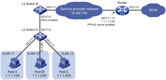
Procedure
# Configure VLANs and QinQ termination. For the configuration procedure, see "Example: Configuring ambiguous QinQ termination." (Details not shown.)
# Configure the router as the PPPoE server. Configure PPPoE settings on GigabitEthernet 3/1/1.10 on the router. For more information about PPPoE configuration, see BRAS Services Configuration Guide. (Details not shown.)
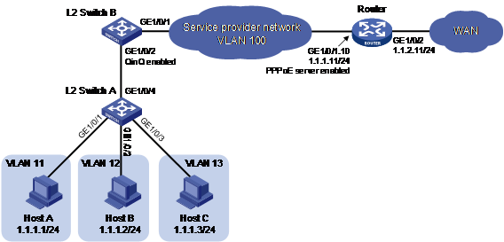
Example: Configuring QinQ termination for PPPoE server (user VLAN termination)
Network configuration
As shown in Figure 9:
· QinQ is enabled on GigabitEthernet 1/0/2 of Layer 2 Switch B.
· The router acts as a PPPoE server. Hosts in different VLANs access the Internet through the PPPoE server.
Configure user VLAN QinQ termination to enable the router to dynamically create QinQ termination entries only for online users.
Figure 10 Network diagram
Procedure
1. Configure Host A, Host B, and Host C:
# Assign the IP addresses 1.1.1.1/24, 1.1.1.2/24, and 1.1.1.3/24 to Host A, Host B, and Host C, respectively. (Details not shown.)
# Specify 1.1.1.11/24 as the gateway address for the hosts. (Details not shown.)
2. Configure Layer 2 Switch A:
# Create VLAN 11.
<L2_SwitchA> system-view
[L2_SwitchA] vlan 11
# Assign GigabitEthernet 1/0/1 to VLAN 11.
[L2_SwitchA-vlan11] port gigabitethernet 1/0/1
[L2_SwitchA-vlan11] quit
# Create VLAN 12.
[L2_SwitchA] vlan 12
# Assign GigabitEthernet 1/0/2 to VLAN 12.
[L2_SwitchA-vlan12] port gigabitethernet 1/0/2
[L2_SwitchA-vlan12] quit
# Create VLAN 13.
[L2_SwitchA] vlan 13
# Assign GigabitEthernet 1/0/3 to VLAN 13.
[L2_SwitchA-vlan13] port gigabitethernet 1/0/3
[L2_SwitchA-vlan13] quit
# Configure GigabitEthernet 1/0/7 as a trunk port, and assign the port to VLANs 11 through 13.
[L2_SwitchA] interface gigabitethernet 1/0/7
[L2_SwitchA-GigabitEthernet1/0/7] port link-type trunk
[L2_SwitchA-GigabitEthernet1/0/7] port trunk permit vlan 11 to 13
3. Configure Layer 2 Switch B:
# Configure GigabitEthernet 1/0/2 as a trunk port, and assign the port to VLANs 11 through 13 and VLAN 100.
<L2_SwitchB> system-view
[L2_SwitchB] interface gigabitethernet 1/0/2
[L2_SwitchB-GigabitEthernet1/0/2] port link-type trunk
[L2_SwitchB-GigabitEthernet1/0/2] port trunk permit vlan 11 to 13 100
# Set the PVID of GigabitEthernet 1/0/2 to VLAN 100.
[L2_SwitchB-GigabitEthernet1/0/2] port trunk pvid vlan 100
# Enable QinQ on GigabitEthernet 1/0/2.
[L2_SwitchB-GigabitEthernet1/0/2] qinq enable
[L2_SwitchB-GigabitEthernet1/0/2] quit
# Configure GigabitEthernet 1/0/1 as a trunk port and assign the port to VLAN 100.
[L2_SwitchB] interface gigabitethernet 1/0/1
[L2_SwitchB-GigabitEthernet1/0/1] port link-type trunk
[L2_SwitchB-GigabitEthernet1/0/1] port trunk permit vlan 100
4. Configure the router:
Configure the router as the PPPoE server. Configure PPPoE settings on GigabitEthernet 1/0/1.10 on the router. For more information about PPPoE configuration, see BRAS Services Configuration Guide.
# Create Layer 3 Ethernet subinterface GigabitEthernet 1/0/1.10.
<Router> system-view
[Router] interface gigabitethernet 1/0/1.10
# Enable PPPoE server on subinterface GigabitEthernet 1/0/1.10 and bind it to an existing VT interface (Virtual-Template 1 in this example).
[Router-GigabitEthernet1/0/1.10] pppoe-server bind virtual-template 1
# Configure user VLAN QinQ termination on GigabitEthernet 1/0/1.10 to terminate VLAN-tagged packets whose Layer 1 VLAN ID is 100 and Layer 2 VLAN ID is 11, 12, or 13.
[Router-GigabitEthernet1/0/1.10] user-vlan dot1q vid 100 second-dot1q 11 to 13
# Assign an IP address to Layer 3 interface GigabitEthernet 1/0/2.
[Router] interface gigabitethernet 1/0/2
[Router-GigabitEthernet1/0/2] ip address 1.1.2.11 255.255.255.0
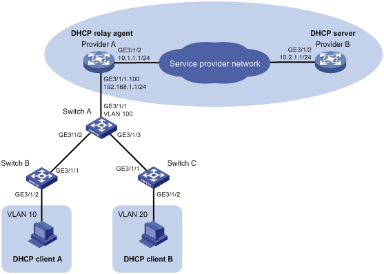
Example: Configuring QinQ termination for DHCP relay
Network configuration
As shown in Figure 11:
· Provider A and Provider B are edge devices on the service provider network.
· DHCP client A and DHCP client B are devices on the customer networks.
· Provider A is the DHCP relay agent. Provider B is the DHCP server.
· Provider A and Provider B communicate with each other through Layer 3 interfaces.
Configure QinQ termination on Provider A so that DHCP client A and DHCP client B can obtain IP settings from Provider B.
Procedure
1. Configure the DHCP relay agent Provider A:
# Enable DHCP service.
<ProviderA> system-view
[ProviderA] dhcp enable
# Create a Layer 3 Ethernet subinterface GigabitEthernet 3/1/1.100.
[ProviderA] interface gigabitethernet 3/1/1.100
# Configure GigabitEthernet 3/1/1.100 to terminate packets whose Layer 1 ID is 100 and Layer 2 VLAN ID is 10 or 20.
[ProviderA-GigabitEthernet3/1/1.100] vlan-type dot1q vid 100 second-dot1q 10 20
# Enable GigabitEthernet 3/1/1.100 to transmit broadcast and multicast packets.
[ProviderA-GigabitEthernet3/1/1.100] vlan-termination broadcast enable
# Enable DHCP relay on GigabitEthernet 3/1/1.100 and specify 10.2.1.1 as the DHCP server address.
[ProviderA-GigabitEthernet3/1/1.100] dhcp select relay
[ProviderA-GigabitEthernet3/1/1.100] dhcp relay server-address 10.2.1.1
# Assign an IP address to GigabitEthernet 3/1/1.100.
[ProviderA-GigabitEthernet3/1/1.100] ip address 192.168.1.1 24
[ProviderA-GigabitEthernet3/1/1.100] quit
# Enable recording of relay entries on the relay agent.
[ProviderA] dhcp relay client-information record
# Assign an IP address to the interface GigabitEthernet 3/1/2.
[ProviderA] interface gigabitethernet 3/1/2
[ProviderA-GigabitEthernet3/1/2] ip address 10.1.1.1 24
[ProviderA-GigabitEthernet3/1/2] quit
# Configure a static route to the DHCP server.
[ProviderA] ip route-static 10.2.1.1 24 10.1.1.1
2. Configure the DHCP server Provider B:
# Assign an IP address to the DHCP server.
<ProviderB> system-view
[ProviderB] interface gigabitethernet 3/1/2
[ProviderB-GigabitEthernet3/1/2] ip address 10.2.1.1 24
[ProviderB-GigabitEthernet3/1/2] quit
# Enable DHCP.
[ProviderB] dhcp enable
# Configure an IP address pool on the DHCP server.
[ProviderB] dhcp server ip-pool 1
[ProviderB-dhcp-pool-1] network 192.168.1.0 24
[ProviderB-dhcp-pool-1] gateway-list 192.168.1.1
[ProviderB-dhcp-pool-1] quit
# Configure a static route to GigabitEthernet 3/1/1.100.
[ProviderB] ip route-static 192.168.1.1 24 10.1.1.1
3. Configure Switch A:
# Configure the uplink port (GigabitEthernet 3/1/1) as a trunk port and assign the port to VLAN 100.
<SwitchA> system-view
[SwitchA] interface gigabitethernet 3/1/1
[SwitchA-GigabitEthernet3/1/1] port link-type trunk
[SwitchA-GigabitEthernet3/1/1] port trunk permit vlan 100
[SwitchA-GigabitEthernet3/1/1] quit
# Configure downlink port GigabitEthernet 3/1/2 as a trunk port, and assign the port to VLAN 100.
[SwitchA] interface gigabitethernet 3/1/2
[SwitchA-GigabitEthernet3/1/2] port link-type trunk
[SwitchA-GigabitEthernet3/1/2] port trunk permit vlan 100
# Set the PVID of GigabitEthernet 3/1/2 to VLAN 100.
[SwitchA-GigabitEthernet3/1/2] port trunk pvid vlan 100
# Enable QinQ on GigabitEthernet3/1/2.
[SwitchA-GigabitEthernet3/1/2] qinq enable
[SwitchA-GigabitEthernet3/1/2] quit
# Configure downlink port GigabitEthernet 3/1/3 as a trunk port, and assign the port to VLAN 100.
[SwitchA] interface gigabitethernet 3/1/3
[SwitchA-GigabitEthernet3/1/3] port link-type trunk
[SwitchA-GigabitEthernet3/1/3] port trunk permit vlan 100
# Set the PVID of GigabitEthernet 3/1/3 to VLAN 100.
[SwitchA-GigabitEthernet3/1/3] port trunk pvid vlan 100
# Enable QinQ on GigabitEthernet 3/1/3.
[SwitchA-GigabitEthernet3/1/3] qinq enable
[SwitchA-GigabitEthernet3/1/3] quit
# Assign GigabitEthernet 3/1/2 and GigabitEthernet 3/1/3 to VLAN 100.
[SwitchA] vlan 100
[SwitchA-vlan100] port gigabitethernet 3/1/2
[SwitchA-vlan100] port gigabitethernet 3/1/3
4. Configure Switch B:
# Create VLAN 10.
<SwitchB> system-view
[SwitchB] vlan 10
# Assign GigabitEthernet 3/1/2 to VLAN 10.
[SwitchB-vlan10] port gigabitethernet 3/1/2
[SwitchB-vlan10] quit
# Configure GigabitEthernet 3/1/1 as a trunk port and assign the port to VLAN 10.
[SwitchB] interface gigabitethernet 3/1/1
[SwitchB-GigabitEthernet3/1/1] port link-type trunk
[SwitchB-GigabitEthernet3/1/1] port trunk permit vlan 10
5. Configure Switch C:
# Create VLAN 20.
<SwitchC> system-view
[SwitchC] vlan 20
# Assign GigabitEthernet 3/1/2 to VLAN 20.
[SwitchC-vlan20] port gigabitethernet 3/1/2
[SwitchC-vlan20] quit
# Configure GigabitEthernet 3/1/1 as a trunk port and assign the port to VLAN 20.
[SwitchC] interface gigabitethernet 3/1/1
[SwitchC-GigabitEthernet3/1/1] port link-type trunk
[SwitchC-GigabitEthernet3/1/1] port trunk permit vlan 20
Verifying the configuration
# Verify that DHCP client A and DHCP client B can obtain IP settings from Provider B. (Details not shown.)