- Table of Contents
- Related Documents
-
| Title | Size | Download |
|---|---|---|
| 01-IRF configuration | 564.90 KB |
File system naming conventions
Multi-active handling procedure
Restrictions and guidelines: IRF configuration
Hardware compatibility with IRF
IRF physical interface configuration restrictions and guidelines
Feature compatibility and configuration restrictions with IRF
Configuration rollback restrictions
Assigning a member ID to each IRF member device
Specifying a priority for each member device
Enabling IRF-Connect mode for IRF connection cards in standalone mode
Binding physical interfaces to IRF ports
Saving configuration to the next-startup configuration file
Connecting IRF physical interfaces·
Setting the IRF link detection interval for IRF establishment over relay devices
Setting the operating mode to IRF mode
Restrictions and guidelines for MAD configuration
Excluding interfaces from the shutdown action upon detection of multi-active collision
Optimizing IRF settings for an IRF fabric
Changing the member ID of a member device
Changing the priority of a member device
Enabling IRF-Connect mode for IRF connection cards in IRF mode
Adding physical interfaces to an IRF port
Bulk-configuring basic IRF settings for a member device
Configuring a member device description
Configuring IRF link load sharing mode
Configuring IRF bridge MAC address settings
Enabling software auto-update for software image synchronization
Setting the IRF link down report delay
Setting the IRF link detection interval for the IRF fabric established over relay devices
Fast-restoring IRF configuration for a one-MPU member
About fast IRF configuration restoration
Restrictions and guidelines for fast IRF configuration restoration
Prerequisites for fast IRF configuration restoration
Fast-restoring IRF configuration by using a two-MPU restoration assistant
Fast-restoring IRF configuration by using a one-MPU restoration assistant
Display and maintenance commands for IRF
Example: Configuring an LACP MAD-enabled IRF fabric with CR16000-F routers
Example: Configuring a BFD MAD-enabled IRF fabric with CR16000-F routers
Example: Enabling IRF-Connect mode in standalone mode
Example: Enabling IRF-Connect mode in IRF mode
Example: Configuring an IRF fabric over relay devices
Example: Restoring standalone mode
Configuring an IRF fabric
About IRF
The Intelligent Resilient Framework (IRF) technology virtualizes multiple physical devices at the same layer into one virtual fabric to provide data center class availability and scalability. IRF virtualization technology offers processing power, interaction, unified management, and uninterrupted maintenance of multiple devices.
IRF network model
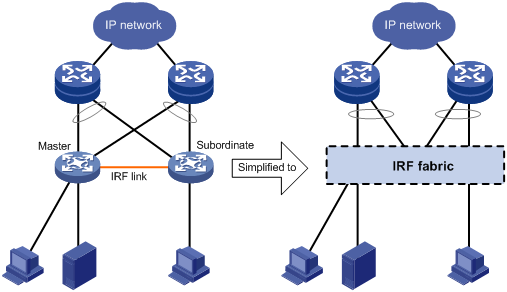
Figure 1 shows an IRF fabric that has two devices, which appear as a single node to the upper-layer and lower-layer devices.
Figure 1 IRF application scenario
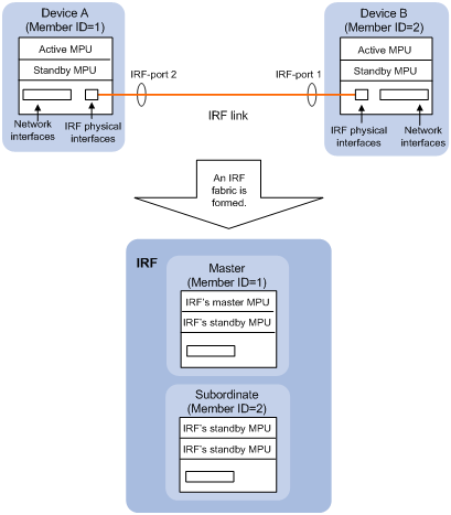
As shown in Figure 2, Device A and Device B form a two-chassis IRF fabric. The fabric has four MPUs (one active and three standbys), and two times the number of interface cards that a single device provides. The IRF fabric manages the physical and software resources of Device A and Device B in a centralized manner.
Figure 2 Two-chassis IRF fabric implementation schematic diagram
IRF benefits
IRF provides the following benefits:
· Simplified topology and easy management—An IRF fabric appears as one node and is accessible at a single IP address on the network. You can use this IP address to log in at any member device to manage all the members of the IRF fabric. In addition, you do not need to run the spanning tree feature among the IRF members.
· 1:N redundancy—In an IRF fabric, one member acts as the master to manage and control the entire IRF fabric. All the other members process services while backing up the master. When the master fails, the remaining member devices elect a new master from among them to take over without interrupting services.
· IRF link aggregation—You can assign several physical links between neighboring members to their IRF ports to create an aggregate IRF connection for load balancing and redundancy.
· Multichassis link aggregation—You can use the Ethernet link aggregation feature to aggregate the physical links between the IRF fabric and its upstream or downstream devices across the IRF members.
· Network scalability and resiliency—Processing capacity of an IRF fabric equals the total processing capacities of all the members. You can increase ports, network bandwidth, and processing capacity of an IRF fabric simply by adding member devices without changing the network topology.
Basic concepts
Operating mode
The device operates in one of the following modes:
· Standalone mode—The device cannot form an IRF fabric with other devices.
· IRF mode—The device can form an IRF fabric with other devices.
IRF member roles
IRF uses two member roles: master and standby (called subordinate throughout the documentation).
When devices form an IRF fabric, they elect a master to manage and control the IRF fabric, and all the other devices back up the master. When the master device fails, the other devices automatically elect a new master. For more information about master election, see "Master election."
IRF member ID
An IRF fabric uses member IDs to uniquely identify and manage its members. This member ID information is included as the first part of interface numbers and file paths to uniquely identify interfaces and files in an IRF fabric. Two devices cannot form an IRF fabric if they use the same member ID. A device cannot join an IRF fabric if its member ID has been used in the fabric.
MPU roles
Each IRF member device has one or two MPUs. The following are MPU roles:
|
Role |
Description |
|
Master MPU |
Active MPU of the master device. It is also called the global active MPU. You configure and manage the entire IRF fabric at the CLI of the global active MPU. |
|
Active MPU |
Active MPU on each member device. An active MPU performs the following tasks: · Manages the local device, including synchronizing configuration with the local standby MPU, processing protocol packets, and creating and maintaining route entries. · Processes IRF-related events, such as master election and topology collection. |
|
Standby MPU |
For the master MPU, all other MPUs are standby MPUs, including active MPUs on subordinate devices. If a member device has two MPUs, the MPU backing up the local active MPU is the local standby MPU from the perspective of the member device. |
Member priority
Member priority determines the possibility of a member device to be elected the master. A member with higher priority is more likely to be elected the master.
IRF port
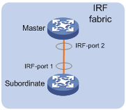
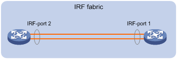
An IRF port is a logical interface that connects IRF member devices. Every IRF-capable device has two IRF ports.
In standalone mode, the IRF ports are named IRF-port 1 and IRF-port 2.
In IRF mode, the IRF ports are named IRF-port n/1 and IRF-port n/2, where n is the member ID of the device. The two IRF ports are referred to as IRF-port 1 and IRF-port 2 in this book.
To use an IRF port, you must bind a minimum of one physical interface to it. The physical interfaces assigned to an IRF port automatically form an aggregate IRF link. An IRF port goes down when all its IRF physical interfaces are down.
IRF physical interface
IRF physical interfaces connect IRF member devices and must be bound to an IRF port. They forward traffic between member devices, including IRF protocol packets and data packets that must travel across IRF member devices.
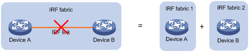
IRF split
IRF split occurs when an IRF fabric breaks up into multiple IRF fabrics because of IRF link failures, as shown in Figure 3. The split IRF fabrics operate with the same IP address. IRF split causes routing and forwarding problems on the network. To quickly detect a multi-active collision, configure a minimum of one MAD mechanism (see "Configuring MAD").
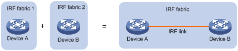
IRF merge
IRF merge occurs when two split IRF fabrics reunite or when two independent IRF fabrics are united, as shown in Figure 4.
MAD
An IRF link failure causes an IRF fabric to split in two IRF fabrics operating with the same Layer 3 settings, including the same IP address. To avoid IP address collision and network problems, IRF uses multi-active detection (MAD) mechanisms to detect the presence of multiple identical IRF fabrics, handle collisions, and recover from faults.
IRF domain ID
One IRF fabric forms one IRF domain. IRF uses IRF domain IDs to uniquely identify IRF fabrics and prevent IRF fabrics from interfering with one another.
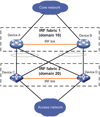
As shown in Figure 5, IRF fabric 1 contains Device A and Device B, and IRF fabric 2 contains Device C and Device D. Both fabrics use the LACP aggregate links between them for MAD. When a member device receives an extended LACPDU for MAD, it checks the domain ID to determine whether the packet is from the local IRF fabric. Then, the member device can handle the packet correctly.
Figure 5 A network that contains two IRF domains
IRF network topology
An IRF fabric can use a daisy-chain topology.
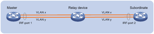
You can connect two distant IRF member devices through relay devices (for example, Layer 2 devices). To use relay devices, you must assign each IRF physical link a unique VLAN to send and receive IRF packets, as shown in Figure 7. The VLANs are called IRF packet VLANs.
Figure 7 Relay device deployment
Master election
Master election occurs each time the IRF fabric topology changes in the following situations:
· The IRF fabric is established.
· The master device fails or is removed.
· The IRF fabric splits.
· Independent IRF fabrics merge.
|
|
NOTE: Master election does not occur when split IRF fabrics merge. For information about the master device of the merged IRF fabric, see "Failure recovery." |
Master election selects a master in descending order:
1. Current master, even if a new member has higher priority.
When an IRF fabric is being formed, all members consider themselves as the master. This rule is skipped.
2. Member with higher priority.
3. Member with the longest system uptime.
Two members are considered to start up at the same time if the difference between their startup times is equal to or less than 10 minutes. For these members, the next tiebreaker applies.
4. Member with the lowest CPU MAC address.
For the setup of a new IRF fabric, the subordinate devices must reboot to complete the setup after the master election.
For an IRF merge, devices must reboot if they are in the IRF fabric that fails the master election.
Interface naming conventions
In standalone mode:
A physical interface is numbered in the format of slot-number/subslot-number/interface-index.
For example, set the link type of Ten-GigabitEthernet 3/0/1 to trunk, as follows:
<Sysname> system-view
[Sysname] interface ten-gigabitethernet 3/1/1
[Sysname-Ten-GigabitEthernet3/1/1] port link-type trunk
In IRF mode:
A physical interface is numbered in the chassis-number/slot-number/subslot-number/interface-index format. The chassis-number argument represents the IRF member ID.
For example, Ten-GigabitEthernet 1/3/1/1 represents the first port in slot 3 on member device 1. Set its link type to trunk, as follows:
<Sysname> system-view
[Sysname] interface ten-gigabitethernet 1/3/1/1
[Sysname-Ten-GigabitEthernet1/3/1/1] port link-type trunk
File system naming conventions
In standalone mode, you can use the storage device name to access the file system of the active MPU. To access the file system of the standby MPU, use the name in the slotslot-number#storage-device-name format.
On a multichassis IRF fabric, you can use the storage device name to access the file system of the global active MPU. To access the file system of a global standby MPU, use the name in the chassismember-ID#slotslot-number#storage-device-name format.
For more information about storage device naming conventions, see Fundamentals Configuration Guide.
For example:
· To create and access the test folder under the root directory of the flash memory on the global active MPU:
<Master> mkdir test
Creating directory flash:/test... Done.
<Master> cd test
<Master> dir
Directory of flash:/test
The directory is empty.
524288 KB total (29832 KB free)
· To create and access the test folder under the root directory of the flash memory in slot 0 on member device 1:
<Master> mkdir chassis1#slot0#flash:/test
Creating directory chassis1#slot0#flash:/test... Done.
<Master> cd chassis1#slot0#flash:/test
<Master> dir
Directory of chassis1#slot0#flash:/test
The directory is empty.
524288 KB total (128812 KB free)
Configuration synchronization
IRF uses a strict running-configuration synchronization mechanism. In an IRF fabric, all MPUs obtain and run the running configuration of the global active MPU. Configuration changes are automatically propagated from the global active MPU to the remaining MPUs. The configuration files of these MPUs are retained, but the files do not take effect. The subordinate devices use their own startup configuration files on their respective local active MPU only after these devices are removed from the IRF fabric.
As a best practice, back up the next-startup configuration file on a device before adding the device to an IRF fabric as a subordinate.
A subordinate device's next-startup configuration file might be overwritten if the master and the subordinate use the same file name for their next-startup configuration files. You can use the backup file to restore the original configuration after removing the subordinate from the IRF fabric.
For more information about configuration management, see Fundamentals Configuration Guide.
Multi-active handling procedure
The multi-active handling procedure includes detection, collision handling, and failure recovery.
Detection
IRF provides MAD mechanisms by extending LACP and BFD to detect multi-active collisions. You can configure a minimum of one MAD mechanism on an IRF fabric.
For more information about the MAD mechanisms and their application scenarios, see "MAD mechanisms."
Collision handling
When detecting a multi-active collision, MAD disables all IRF fabrics except one from forwarding data traffic by placing them in Recovery state. The IRF fabrics placed in Recovery state are called inactive IRF fabrics. The IRF fabric that continues to forward traffic is called the active IRF fabric.
LACP MAD and BFD MAD use the following process to handle a multi-active collision:
1. Compare the number of members in each fabric.
2. Set all fabrics to the Recovery state except the one that has the most members.
3. Compare the member IDs of the masters if all IRF fabrics have the same number of members.
4. Set all fabrics to the Recovery state except the one that has the lowest numbered master.
5. Shut down all common network interfaces in the Recovery-state fabrics except for the following interfaces:
? Interfaces automatically excluded from being shut down by the system.
? Interfaces specified by using the mad exclude interface command.
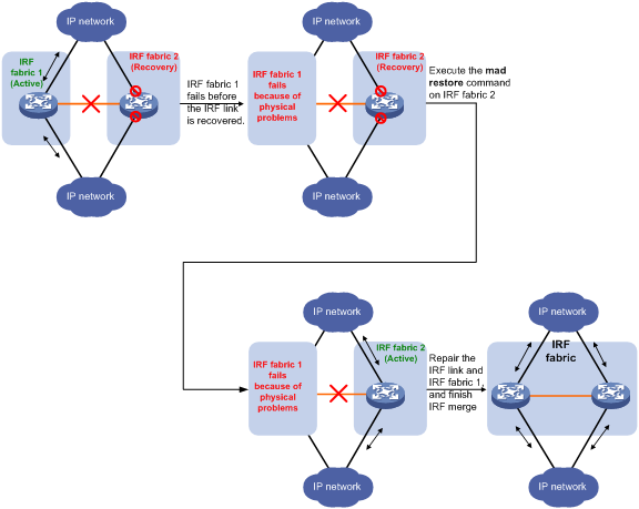
Failure recovery
To merge two split IRF fabrics, first repair the failed IRF link and remove the IRF link failure.
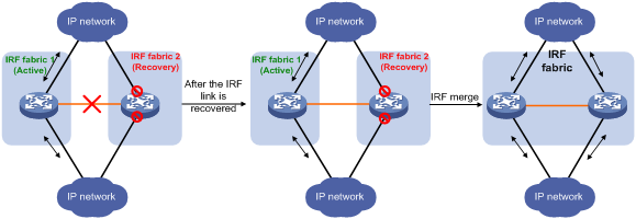
After the failed IRF link between two split IRF fabrics is recovered, log in to the inactive IRF fabric to reboot its member devices if the system requires you to do so. After these member devices join the active IRF fabric as subordinate devices, the IRF merge is complete, as shown in Figure 8. The network interfaces that have been shut down by MAD automatically restore their original state.
|
|
CAUTION: If you inadvertently reboot the active IRF fabric after the failed IRF link recovers, its member devices will join the inactive IRF fabric with their network interfaces shut down by MAD. To restore the original states of the network interfaces in the merged IRF fabric, use the mad restore command. |
|
|
NOTE: If the IRF auto-merge feature is enabled, the inactive IRF member devices will automatically reboot after the failed IRF link recovers and a manual reboot is typically not required. |
Figure 8 Recovering the IRF fabric
If the active IRF fabric fails before the IRF link is recovered (see Figure 9), use the mad restore command on the inactive IRF fabric to recover the inactive IRF fabric. This command brings up all network interfaces that were shut down by MAD. After the IRF link is repaired, merge the two parts into a unified IRF fabric.
Figure 9 Active IRF fabric fails before the IRF link is recovered
MAD mechanisms
Table 1 compares the MAD mechanisms and their application scenarios.
Table 1 Comparison of MAD mechanisms
|
MAD mechanism |
Advantages |
Disadvantages |
Application scenario |
|
· Detection speed is fast. · Runs on existing aggregate links without requiring MAD-dedicated physical links or Layer 3 interfaces. |
Requires an intermediate device that supports extended LACP. |
Link aggregation is used between the IRF fabric and its upstream or downstream device. For information about LACP, see Layer 2—LAN Switching Configuration Guide. |
|
|
· Detection speed is fast. · No intermediate device is required. · Intermediate device, if used, can come from any vendor. |
· Requires MAD dedicated physical links and VLAN interfaces, which cannot be used for transmitting user traffic. · If no intermediate device is used, any two IRF members must have a BFD MAD link to each other. · If an intermediate device is used, every IRF member must have a BFD MAD link to the intermediate device. |
· No special requirements for network scenarios. · If no intermediate device is used, this mechanism is only suitable for IRF fabrics that have a small number of members that are geographically close to one another. For information about BFD, see High Availability Configuration Guide. |
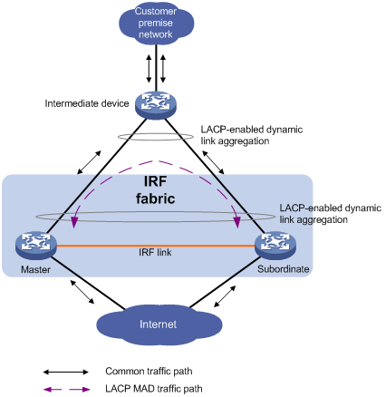
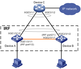
LACP MAD
As shown in Figure 10, LACP MAD has the following requirements:
· Every IRF member must have a link with an intermediate device.
· All the links form a dynamic link aggregation group.
· The intermediate device must be a device that supports extended LACP.
The IRF member devices send extended LACPDUs that convey a domain ID and an active ID (the member ID of the master). The intermediate device transparently forwards the extended LACPDUs received from one member device to all the other member devices.
· If the domain IDs and active IDs sent by all the member devices are the same, the IRF fabric is integrated.
· If the extended LACPDUs convey the same domain ID but different active IDs, a split has occurred. LACP MAD handles this situation as described in "Collision handling."
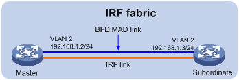
BFD MAD
BFD MAD can work with or without an intermediate device. Figure 11 shows a typical BFD MAD application scenario that uses an intermediate device. Figure 12 shows a typical BFD MAD scenario that does not use an intermediate device.
To use BFD MAD:
· Set up dedicated BFD MAD link between each pair of IRF members or between each IRF member and the intermediate device. Do not use the BFD MAD links for any other purposes.
· Assign the ports connected by BFD MAD links to the same VLAN.
· Create a VLAN interface for the VLAN, and assign a MAD IP address to each member on the VLAN interface.
|
|
NOTE: The MAD IP addresses identify the member devices and must belong to the same subnet. |
· If the IRF fabric is integrated, only the MAD IP address of the master takes effect. The master cannot establish a BFD session with any other member. If you execute the display bfd session command, the state of the BFD sessions is Down.
· When the IRF fabric splits, the IP addresses of the masters in the split IRF fabrics take effect. The masters can establish a BFD session. If you execute the display bfd session command, the state of the BFD session between the two devices is Up.
Figure 11 BFD MAD scenario with an intermediate device
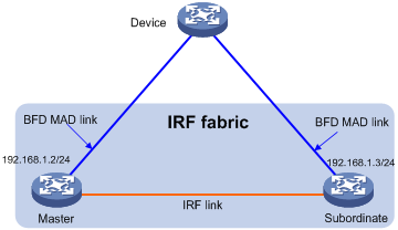
Figure 12 BFD MAD scenario without an intermediate device
Restrictions and guidelines: IRF configuration
Hardware compatibility with IRF
To establish an IRF fabric successfully, make sure the member device models, their IRF physical interfaces, and switching fabric modules meet the compatibility requirements in Table 2. For more information about IRF physical interface configuration restrictions, see "IRF physical interface configuration restrictions and guidelines."
Table 2 Hardware compatibility matrix for IRF establishment
|
Hardware platform |
IRF members |
IRF physical interfaces |
Switching fabric module requirements |
|
CR16006-F CR16010-F CR16014-F |
Any combination of these router models. |
10-GE or 40-GE Ethernet fiber ports on CSPC cards (except the CSPC-GE16XP4L-E, CSPC-GE24L-E, and CSPC-GP24GE8XP2L-E cards).
You must use CSPC cards across all member devices for IRF connection. All IRF physical interfaces must be the same speed. |
Use either of the following schemes: · Use Type-A switching fabric modules across the entire IRF fabric. · Use Type-B and Type-D switching fabric modules. ? On a member device, use Type-B or Type-D modules, but not both. ? Different types of switching fabric modules can be used between member devices. |
|
CR16006-F CR16010-F CR16010H-F CR16014-F CR16018-F |
All members are the same model. |
10-GE, 40-GE, or 100-GE Ethernet fiber ports on CSPEX cards (except the CSPEX-1204 and CSPEX-1104-E cards) or CEPC cards.
You must use CSPEX or CEPC cards, but not both, across IRF member devices for IRF connection. All IRF physical interfaces must be the same speed. Do not install WAN interface subcards on the CSPEX or CEPC cards used for IRF connection. Do not configure the device with CSPC cards (except the CSPC-GE16XP4L-E, CSPC-GE24L-E, and CSPC-GP24GE8XP2L-E cards) or the CMPE-1104 card, which cannot work when CSPEX or CEPC cards are used for IRF connection. |
All member devices use same model switching fabric modules. |
MPU requirements for IRF
To form a CR16000-F IRF fabric, every member device must use the same model of MPUs.
Software requirements for IRF
All IRF member devices must run the same software image version. Make sure the software auto-update feature is enabled on all member devices.
IRF fabric size
An IRF fabric can contain a maximum of two member devices.
IRF port connection
When you connect two neighboring IRF members, follow these restrictions and guidelines:
· You must connect the physical interfaces of IRF-port 1 on one member to the physical interfaces of IRF-port 2 on the other.
· For high availability, you can bind a maximum of eight physical interfaces to an IRF port.
Figure 13 Connecting IRF physical interfaces
IRF physical interface configuration restrictions and guidelines
Hardware-related configuration restrictions and guidelines
To ensure system performance, you must execute the irf-connect mode enable command to set the cards that are used for IRF connection in IRF-Connect mode. In this mode, these cards are dedicated to providing IRF links and BFD MAD services. You cannot configure any network services other than BFD MAD on them.
If you use a CSPEX or CEPC card for IRF connection, follow these restrictions and guidelines:
· You must reboot the card in the following situations:
? The first time you bind ports on the card to an IRF port, you must reboot the card for the bindings to take effect.
? To use the card to provide network services after you disconnect all its IRF physical links and remove all its IRF port bindings, you must reboot the card.
· After you place the device in IRF mode, all Ethernet ports on the card automatically change to bridge mode to operate as Layer 2 interfaces. You can use these ports only for IRF connections or BFD MAD
· When you replace a subcard on the card in IRF mode, make sure the replacement subcard is the same model as the replaced subcard.
Command restrictions
On a physical interface bound to an IRF port, you can execute only the following commands:
· Interface commands, including description and shutdown.
For more information about these commands, see Ethernet interface in Interface Command Reference.
· The following LLDP commands:
? lldp admin-status.
? lldp check-change-interval.
? lldp enable.
? lldp encapsulation snap.
? lldp notification remote-change enable.
? lldp tlv-enable.
For more information about these commands, see Layer 2—LAN Switching Command Reference.
· The port service-loopback group command, which assigns the physical interface to a service loopback group. For more information about this command, see Layer 2—LAN Switching Command Reference.
· The mirroring-group reflector-port command, which specifies the physical interface as the reflector port for remote mirroring. For more information about this command, see Network Management and Monitoring Command Reference.
|
|
IMPORTANT: Do not execute the port service-loopback group or mirroring-group reflector-port command on an IRF physical interface if that interface is the only member interface of an IRF port. Doing so will split the IRF fabric, because these commands remove the binding between a physical interface and IRF port. |
Suppressing SNMP notifications of packet drops on IRF physical interfaces
Before an IRF member device forwards a packet, it examines its forwarding path in the IRF fabric for a loop. If a loop exists, the device discards the packet on the source interface of the looped path. This loop elimination mechanism will drop a large number of broadcast packets on the IRF physical interfaces.
To suppress SNMP notifications of packet drops that do not require attention, do not monitor packet forwarding on the IRF physical interfaces.
Feature compatibility and configuration restrictions with IRF
To form an IRF fabric, all member devices must use the same VLAN mode (set by using the system-vlan-mode command). For more information about setting the VLAN mode, see VLAN configuration in Layer 2—LAN Switching Configuration Guide.
Configuration rollback restrictions
The configuration rollback feature cannot roll back the following IRF settings:
· Member device description (set by using the irf member description command).
· Member device priority (set by using the irf member priority command).
· IRF physical interface and IRF port bindings (set by using the port group interface command).
For more information about the configuration rollback feature, see configuration file management in Fundamentals Configuration Guide.
IRF tasks at a glance
To configure IRF, perform the following tasks:
a. Assigning a member ID to each IRF member device
b. (Optional.) Specifying a priority for each member device
c. Enabling IRF-Connect mode for IRF connection cards in standalone mode
d. Binding physical interfaces to IRF ports
e. Saving configuration to the next-startup configuration file
f. Connecting IRF physical interfaces
g. Setting the IRF link detection interval for IRF establishment over relay devices
h. Setting the operating mode to IRF mode
Configure a minimum of one MAD mechanism on an IRF fabric.
? Excluding interfaces from the shutdown action upon detection of multi-active collision
This feature excludes an interface from the shutdown action for management or other special purposes when an IRF fabric transits to the Recovery state.
3. (Optional.) Optimizing IRF settings for an IRF fabric
? Changing the member ID of a member device
Changing member IDs in an IRF fabric can void member ID-related configuration and cause unexpected problems. Make sure you understand the impact on your live network before you change member IDs.
? Changing the priority of a member device
? Enabling IRF-Connect mode for IRF connection cards in IRF mode
? Adding physical interfaces to an IRF port
? Bulk-configuring basic IRF settings for a member device
You can configure member IDs, priorities, domain ID, IRF physical interfaces separately or in bulk.
? Enabling IRF auto-merge
When two IRF fabrics merge, this feature enables the IRF fabric that failed the master election to automatically reboot all its member devices to complete the merge.
? Configuring a member device description
? Configuring IRF link load sharing mode
? Configuring IRF bridge MAC address settings
? Enabling software auto-update for software image synchronization
This feature automatically propagates the software images of the global active MPU to all other MPUs in the IRF fabric.
? Setting the IRF link down report delay
? Setting the IRF link detection interval for the IRF fabric established over relay devices
4. (Optional.) Fast-restoring IRF configuration for a one-MPU member
This task helps you fast-restore IRF configuration for one-MPU members before an MPU replacement.
Planning the IRF fabric setup
Consider the following items when you plan an IRF fabric:
· Hardware compatibility and restrictions.
· IRF fabric size.
· Master device.
· Member ID and priority assignment scheme.
· Fabric topology and cabling scheme.
· IRF physical interfaces.
Setting up an IRF fabric
Assigning a member ID to each IRF member device
About assigning an IRF member ID
Assign a unique IRF member ID to a device before changing the device's operating mode to IRF. If you do not assign a member ID to the device, the device automatically uses the member ID of 1 after the mode changes to IRF.
The member ID assigned to the device is saved in both active and standby MPUs. The standby MPU might store a different member ID than the active MPU after an MPU replacement. For consistency, the system updates the member ID in the active MPU automatically to the standby MPU when the difference is detected.
Procedure
1. Enter system view.
system-view
2. Assign an IRF member ID to the device.
irf member member-id
By default, the device operates in standalone mode and does not have an IRF member ID.
Specifying a priority for each member device
About specifying an IRF member priority
IRF member priority represents the possibility for a device to be elected the master in an IRF fabric. A larger priority value indicates a higher priority.
Procedure
1. Enter system view.
system-view
2. Specify a priority for the device in standalone mode.
irf priority priority
The default IRF member priority is 1.
Enabling IRF-Connect mode for IRF connection cards in standalone mode
About IRF-Connect mode
On the CR16006-F, CR16010-F, or CR16014-F router, you must configure cards that are used for IRF connection to operate in IRF-Connect mode. In IRF-Connect mode, these cards are dedicated to providing IRF links and BFD MAD services. You cannot configure any network services other than BFD MAD on them.
Hardware and feature compatibility
IRF-Connect mode is supported only on the CR16006-F, CR16010-F, and CR16014-F routers.
Restrictions and guidelines
You can perform this task when both member devices are in standalone mode, after the planned master device changes to IRF mode, or after the IRF fabric is established.
· If both member devices are in standalone mode, you must perform this task on both member devices.
· If the planned master device has changed to IRF mode or the IRF fabric has been established, you need to perform this task only on the master device.
Prerequisites
The port settings on a card are restored to the default after you enable IRF-Connect mode and reboot that card. To retain those port settings for future use, back up the configuration before you reboot the card.
Procedure
1. On the planned master device, enter system view.
system-view
2. Enable IRF-Connect mode for each IRF connection card, including the cards on the master and subordinate devices.
irf-connect mode enable chassisid chassis-number slotid slot-number
By default, IRF-Connect mode is disabled for a card.
3. Repeat the previous steps on the planned subordinate device.
Binding physical interfaces to IRF ports
About IRF port binding
In standalone mode, IRF port binding operations do not affect the current configuration of the interface. However, when the operating mode changes to IRF mode, the default configuration is restored on the physical interface.
Hardware and feature compatibility
Only the IRF physical interfaces on the following cards support VLAN-based IRF deployment over Layer 2 relay devices:
· CSPEX cards (except the CSPEX-1204 and CSPEX-1104-E cards).
· CEPC cards.
Restrictions and guidelines
If you are using a VLAN-based IRF deployment over Layer 2 relay devices, you must specify a VLAN on the IRF physical interfaces at the two ends of each IRF link, as follows:
· Specify a unique VLAN for each IRF physical link.
· Make sure the two ends of each IRF physical link use the same VLAN ID.
If you are using a VLAN-based IRF deployment over Layer 2 relay devices, make sure the interfaces of the relay devices on each IRF physical link meet the following requirements:
· The spanning tree feature is disabled on all the interfaces.
· The link type of these interfaces cannot be access.
· If the link type of an interface is trunk, make sure the interface permits the traffic from the IRF packet VLAN to pass through and the IRF packet VLAN is not the PVID of the trunk interface.
· If the link type of an interface is hybrid, make sure the hybrid interface is a tagged member of the IRF packet VLAN.
Procedure
1. Enter system view.
system-view
2. Enter IRF port view in standalone mode.
irf-port irf-port-number
3. Bind a physical interface to the IRF port.
port group interface interface-type interface-number [ mode enhanced ] [ vlan vlan-id ]
By default, no physical interfaces are bound to an IRF port.
Repeat this step to assign a maximum of eight physical interfaces to the IRF port.
Saving configuration to the next-startup configuration file
About saving the running configuration
Save the running configuration before converting to the IRF mode. A mode change requires a reboot, which causes all unsaved settings to be lost.
Procedure
To save the running configuration to the next-startup configuration file, execute the following command in any view:
save [ safely ] [ backup | main ] [ force ]
For more information about this command, see configuration file management in Fundamentals Command Reference.
Connecting IRF physical interfaces
Follow the restrictions in "IRF port connection" to connect IRF physical interfaces as well as based on the topology and cabling scheme.
Setting the IRF link detection interval for IRF establishment over relay devices
About the IRF link detection interval
This feature helps quick detection of IRF link failure to eliminate packet loss when IRF connections are established over Layer 2 relay devices between remote IRF member devices. If a member device has not received any IRF link detection packet from its neighboring member on an IRF link within three IRF link detection intervals, the member device reports the link failure to the CPU and redirects traffic to another IRF link. This link down event report will not be delayed by the irf link-delay command.
Hardware and feature compatibility
This feature is applicable only when ports on CSPEX cards (except the CSPEX-1204 and CSPEX-1104-E cards) or CEPC cards are used to establish IRF connections between remote IRF member devices over relay devices.
Restrictions and guidelines
For this feature to operate correctly, you must specify a unique IRF packet VLAN for the physical interfaces of each IRF link.
As a best practice, set the IRF link detection interval to 10 milliseconds if the following intervals are set to 100 milliseconds:
· The minimum interval for receiving BFD echo packets.
· The minimum interval for sending and receiving BFD single-hop control packets.
· The minimum interval for sending and receiving BFD multi-hop control packets.
Procedure
1. Enter system view.
system-view
2. Set the IRF link detection interval.
irf link-detect-time interval
By default, the IRF link detection interval is 100 milliseconds.
Setting the operating mode to IRF mode
About setting IRF mode
By default, the device operates in standalone mode. To assign the device to an IRF fabric, you must change its operating mode to IRF mode.
After you change the operating mode, the device automatically reboots for the change to take effect.
Restrictions and guidelines
During the reboot, you may choose to have the system automatically convert the startup configuration file. Automatic configuration conversion prevents slot- or interface-related settings from becoming invalid. For example, the system adds member ID information to interface numbers and file paths in IRF mode.
Prerequisites
Before you change the operating mode, verify that a unique IRF member ID has been assigned to the device. If you do not assign a member ID to the device, the device automatically uses member ID 1 after the mode changes to IRF.
Procedure
1. Enter system view.
system-view
2. Set the operating mode to IRF mode.
chassis convert mode irf
The default operating mode is standalone mode.
IRF generates packets on a device in IRF mode even if the device does not form an IRF fabric with any other devices. To conserve system resources, set a device to standalone mode after removing it from an IRF fabric. To restore the standalone mode, use the undo chassis convert mode command.
Accessing the IRF fabric
The following methods are available for accessing an IRF fabric:
· Local login—Log in through the AUX or console port of any member device.
· Remote login—Log in at a Layer 3 interface on any member device by using methods including Telnet and SNMP.
The IRF fabric appears as one device after it is formed. When you log in to an IRF fabric, you are placed at the CLI of the global active MPU, regardless of at which member device you are logged in. You configure and manage all IRF members at the CLI of the global active MPU. All settings you have made are automatically propagated to the IRF members.
For more information, see login configuration in Fundamentals Configuration Guide.
Configuring MAD
Restrictions and guidelines for MAD configuration
Assigning IRF domain IDs
If LACP MAD runs between two IRF fabrics, assign each fabric a unique IRF domain ID. (For BFD MAD, this task is optional.)
An IRF fabric has only one IRF domain ID. You can change the IRF domain ID by using the irf domain or mad enable command. The IRF domain IDs configured by using the commands overwrite each other.
Bringing up interfaces shut down by MAD
To prevent an interface from being shut down when the IRF fabric transits to the Recovery state, use the mad exclude interface command.
To bring up the interfaces shut down by a MAD mechanism in a Recovery-state IRF fabric, use the mad restore command instead of the undo shutdown command. The mad restore command activates the Recovery-state IRF fabric.
Configuring LACP MAD
1. Enter system view.
system-view
2. Assign a domain ID to the IRF fabric.
irf domain domain-id
The default IRF domain ID is 0.
3. Create an aggregate interface and enter aggregate interface view.
? Enter Layer 2 aggregate interface view.
interface bridge-aggregation interface-number
? Enter Layer 3 aggregate interface view.
interface route-aggregation interface-number
Perform this step also on the intermediate device.
4. Configure the aggregation group to operate in dynamic aggregation mode.
link-aggregation mode dynamic
By default, an aggregation group operates in static aggregation mode.
LACP MAD takes effect only on dynamic aggregate interfaces.
Perform this step also on the intermediate device.
5. Enable LACP MAD.
mad enable
By default, LACP MAD is disabled.
6. Return to system view.
quit
7. Enter Ethernet interface view or interface range view.
? Enter Ethernet interface view.
interface interface-type interface-number
? Enter interface range view. Choose one of the following commands:
interface range { interface-type interface-number [ to interface-type interface-number ] } &<1-24>
interface range name name [ interface { interface-type interface-number [ to interface-type interface-number ] } &<1-24> ]
To assign a range of ports to the aggregation group, enter interface range view.
To assign one port to the aggregation group, enter Ethernet interface view.
8. Assign the Ethernet port or the range of Ethernet ports to the specified aggregation group.
port link-aggregation group group-id
Multichassis link aggregation is allowed.
Perform this step also on the intermediate device.
Configuring BFD MAD
Restrictions and guidelines
As a best practice, use the following procedure to set up BFD MAD:
1. Choose a BFD MAD link scheme as described in "BFD MAD."
2. Configure BFD MAD.
3. Connect the BFD MAD links.
If you use CSPEX cards (except the CSPEX-1204 and CSPEX-1104-E cards) or CEPC cards for IRF connection, you must follow these guidelines when you plan the BFD MAD link scheme:
· Make sure the BFD MAD ports are all located on the IRF connection cards or none of them are located on the IRF connection cards.
· If BFD MAD ports are on the IRF connection cards, you can configure only one BFD MAD port on each card.
When you configure BFD MAD settings, follow these restrictions and guidelines:
|
Category |
Restrictions and guidelines |
|
BFD MAD VLAN |
· Do not enable BFD MAD on VLAN-interface 1. · If you are using an intermediate device, perform the following tasks: ? On the IRF fabric and the intermediate device, create a VLAN for BFD MAD. ? On the IRF fabric and the intermediate device, assign the ports of BFD MAD links to the BFD MAD VLAN. ? On the IRF fabric, create a VLAN interface for the BFD MAD VLAN. · Make sure the IRF fabrics on the network use different BFD MAD VLANs. · Make sure the BFD MAD VLAN contains only ports on the BFD MAD links. Exclude a port from the BFD MAD VLAN if that port is not on a BFD MAD link. If you have assigned that port to all VLANs by using the port trunk permit vlan all command, use the undo port trunk permit command to exclude that port from the BFD MAD VLAN. |
|
BFD MAD VLAN and feature compatibility |
Do not use the BFD MAD VLAN for any purposes other than BFD MAD. · Use only the mad bfd enable and mad ip address commands on the BFD MAD-enabled VLAN interface. If you configure other features, both BFD MAD and other features on the interface might run incorrectly. · Disable the spanning tree feature on any Layer 2 Ethernet ports in the BFD MAD VLAN. The MAD feature is mutually exclusive with the spanning tree feature. · Do not assign IRF physical interfaces to the BFD MAD VLAN. · If you are using a VLAN-based IRF deployment over Layer 2 relay devices, do not use the BFD MAD VLAN on the relay devices for any purposes other than BFD MAD. |
|
MAD IP address |
· To avoid network issues, only use the mad ip address command to configure IP addresses on the BFD MAD-enabled VLAN interface. Do not configure an IP address by using the ip address command or configure a VRRP virtual address on the BFD MAD-enabled VLAN interface. · Make sure all the MAD IP addresses are on the same subnet. |
Procedure
1. Enter system view.
system-view
2. (Optional.) Assign a domain ID to the IRF fabric.
irf domain domain-id
By default, the domain ID of an IRF fabric is 0.
3. Create a VLAN dedicated to BFD MAD.
vlan vlan-id
By default, only VLAN 1 exists.
Do not enable BFD MAD on VLAN-interface 1.
Perform this step also on the intermediate device (if any).
4. Return to system view.
quit
5. Enter Ethernet interface view or interface range view.
? Enter Ethernet interface view.
interface interface-type interface-number
? Enter interface range view. Choose one of the following commands:
interface range { interface-type interface-number [ to interface-type interface-number ] } &<1-24>
interface range name name [ interface { interface-type interface-number [ to interface-type interface-number ] } &<1-24> ]
To assign a range of ports to the BFD MAD VLAN, enter interface range view.
To assign one port to the BFD MAD VLAN, enter Ethernet interface view.
6. Assign the port or the range of ports to the BFD MAD VLAN.
? Assign the ports to the VLAN as access ports.
port access vlan vlan-id
? Assign the ports to the VLAN as trunk ports.
port trunk permit vlan vlan-id
? Assign the ports to the VLAN as hybrid ports.
port hybrid vlan vlan-id { tagged | untagged }
The link type of BFD MAD ports can be access, trunk, or hybrid.
The default link type of a port is access.
Perform this step also on the intermediate device (if any).
7. Configure the ports as dedicated BFD MAD ports.
mad bfd dedicated
By default, a Layer 2 Ethernet port is not BFD MAD dedicated.
This command helps avoid loops in the BFD MAD VLAN. Do not use this command on any ports except the ports used for BFD MAD. A dedicated BFD MAD port processes only BFD MAD packets with all other packets dropped.
If you use ports on CSPEX cards (except the CSPEX-1204 and CSPEX-1104-E cards) or CEPC cards for BFD MAD and the cards have IRF physical interfaces, you can configure only one port as a dedicated BFD MAD port on each card.
8. Return to system view.
quit
9. Enter VLAN interface view.
interface vlan-interface vlan-interface-id
10. Enable BFD MAD.
mad bfd enable
By default, BFD MAD is disabled.
11. Assign a MAD IP address to a member device on the VLAN interface.
mad ip address ip-address { mask | mask-length } member member-id
By default, no MAD IP addresses are configured on a VLAN interface.
Repeat this step to assign a MAD IP address to each member device on the VLAN interface.
Excluding interfaces from the shutdown action upon detection of multi-active collision
About excluding interfaces from being shut down
When an IRF fabric transits to the Recovery state, the system automatically excludes the following network interfaces from being shut down:
· IRF physical interfaces.
· Member interfaces of an aggregate interface if the aggregate interface is excluded from being shut down.
You can exclude an interface from the shutdown action for management or other special purposes. For example:
· Exclude a port from the shutdown action so you can Telnet to the port for managing the device.
· Exclude a VLAN interface and its Layer 2 ports from the shutdown action so you can log in through the VLAN interface.
Restrictions and guidelines
When you configure this feature, follow these restrictions and guidelines:
· If the Layer 2 ports of a VLAN interface are distributed on multiple member devices, the exclusion operation might introduce IP collision risks. The VLAN interface might be up on both active and inactive IRF fabrics.
· Do not exclude the following interfaces from the shutdown action:
? Aggregate interfaces used for MAD and their member ports.
? VLAN interfaces used for MAD and the Ethernet ports in the VLANs.
Procedure
1. Enter system view.
system-view
2. Configure an interface to not shut down when the IRF fabric transits to the Recovery state.
mad exclude interface interface-type interface-number
By default, all network interfaces on a Recovery-state IRF fabric are shut down, except for the network interfaces automatically excluded by the system.
Recovering an IRF fabric
About recovering an IRF fabric
If the active IRF fabric fails before the IRF link is recovered, perform this task on the inactive IRF fabric to recover the inactive IRF fabric for traffic forwarding. The manual recovery operation brings up all interfaces that were shut down by MAD on the inactive IRF fabric.
Procedure
1. Enter system view.
system-view
2. Recover the inactive IRF fabric.
mad restore
Optimizing IRF settings for an IRF fabric
Changing the member ID of a member device
Restrictions and guidelines
|
|
CAUTION: In IRF mode, an IRF member ID change can invalidate member ID-related settings and cause data loss. Make sure you fully understand its impact on your live network. |
The new member ID takes effect at reboot. After the device reboots, the settings on all member ID-related physical resources (including common physical network interfaces) are removed, regardless of whether you have saved the configuration.
Procedure
1. Enter system view.
system-view
2. Change the member ID of a member device.
irf member member-id renumber new-member-id
By default, the device uses the member ID that is set in standalone mode.
3. Save the running configuration.
save [ safely ] [ force ]
4. Reboot the member device.
reboot chassis chassis-number
The chassis-number must be the same as the member-id specified in the irf member member-id renumber new-member-id command.
Changing the priority of a member device
About changing IRF member priority
You can change the priority of a member device so it can be elected the master in the next master election.
A change to member priority can affect the master re-election result. However, it does not cause an immediate master re-election.
Procedure
1. Enter system view.
system-view
2. Specify a priority for a member of an IRF fabric.
irf member member-id priority priority
The default IRF member priority is 1.
Enabling IRF-Connect mode for IRF connection cards in IRF mode
About IRF-Connect mode
See "Enabling IRF-Connect mode for IRF connection cards in standalone mode."
Feature and hardware compatibility
IRF-Connect mode is supported only on the CR16006-F, CR16010-F, and CR16014-F routers.
Restrictions and guidelines
|
|
CAUTION: This feature requires a card reboot to take effect and will cause a transient IRF split when you configure the feature on an IRF fabric. As a best practice to ensure service continuity, configure this feature before the IRF fabric is established. |
You can perform this task when both member devices are in standalone mode, after the planned master device changes to IRF mode, or after the IRF fabric is established.
· If both member devices are in standalone mode, you must perform this task on both member devices.
· If the planned master device has changed to IRF mode or the IRF fabric has been established, you need to perform this task only on the master device.
Prerequisites
The port settings on a card are restored to the default after you enable IRF-Connect mode and reboot that card. To retain those port settings for future use, back up the configuration before you reboot the card.
Procedure
1. On the IRF fabric, enter system view.
system-view
2. Enable IRF-Connect mode for each IRF connection card, including the cards on the master and subordinate devices.
irf-connect mode enable chassisid chassis-number slotid slot-number
By default, IRF-Connect mode is disabled for a card.
Adding physical interfaces to an IRF port
Hardware and feature compatibility
Only the IRF physical interfaces on the following cards support VLAN-based IRF deployment over Layer 2 relay devices:
· CSPEX cards (except the CSPEX-1204 and CSPEX-1104-E cards).
· CEPC cards.
Restrictions and guidelines
If you are using a VLAN-based IRF deployment over Layer 2 relay devices, you must specify a VLAN on the IRF physical interfaces at the two ends of each IRF link, as follows:
· Specify a unique VLAN for each IRF physical link.
· Make sure the two ends of each IRF physical link use the same VLAN ID.
If you are using a VLAN-based IRF deployment over Layer 2 relay devices, make sure the interfaces of the relay devices on each IRF physical link meet the following requirements:
· The spanning tree feature is disabled on all the interfaces.
· The link type of these interfaces cannot be access.
· If the link type of an interface is trunk, make sure the interface permits the traffic from the IRF packet VLAN to pass through and the IRF packet VLAN is not the PVID of the trunk interface.
· If the link type of an interface is hybrid, make sure the hybrid interface is a tagged member of the IRF packet VLAN.
Procedure
1. Enter system view.
system-view
2. Enter Ethernet interface view or interface range view.
? Enter Ethernet interface view.
interface interface-type interface-number
? Enter interface range view. Choose one of the following commands:
interface range { interface-type interface-number [ to interface-type interface-number ] } &<1-24>
interface range name name [ interface { interface-type interface-number [ to interface-type interface-number ] } &<1-24> ]
To shut down one IRF physical interface, enter its interface view.
To shut down a range of IRF physical interfaces, enter interface range view.
3. Shut down the physical interfaces.
shutdown
By default, a physical interface is not manually shut down.
If you cannot shut down a physical interface, follow the system instruction to shut down its peer interface.
4. Return to system view.
quit
5. Enter IRF port view.
irf-port member-id/irf-port-number
6. Bind each physical interface to the IRF port.
port group interface interface-type interface-number [ mode enhanced ] [ vlan vlan-id ]
By default, no physical interfaces are bound to an IRF port.
Repeat this step to assign a maximum of eight physical interfaces to the IRF port.
7. Return to system view.
quit
8. Enter Ethernet interface view or interface range view.
? Enter Ethernet interface view.
interface interface-type interface-number
? Enter interface range view. Choose one of the following commands:
interface range { interface-type interface-number [ to interface-type interface-number ] } &<1-24>
interface range name name [ interface { interface-type interface-number [ to interface-type interface-number ] } &<1-24> ]
9. Bring up the physical interfaces.
undo shutdown
10. Return to system view.
quit
11. Save the running configuration.
save
Activating IRF port settings causes IRF merge and reboot. To avoid data loss, save the running configuration to the startup configuration file before you perform the operation.
12. Activate the configuration on the IRF port.
irf-port-configuration active
After this step is performed, the state of the IRF port changes to UP. The member devices elect a master, and the subordinate device reboots automatically.
After the IRF fabric is formed, you can add physical interfaces to an IRF port (in UP state) without repeating this step.
Bulk-configuring basic IRF settings for a member device
About easy IRF
Use the easy IRF feature to bulk-configure basic IRF settings for a device in IRF mode, including the member ID, domain ID, priority, and IRF port bindings.
The easy IRF feature provides the following configuration methods:
· Interactive method—Enter the easy-irf command without parameters. The system will guide you to set the parameters step by step.
· Non-interactive method—Enter the easy-irf command with parameters.
As a best practice, use the interactive method if you are new to IRF.
Restrictions and guidelines
The device reboots immediately after you specify a new member ID for it. Make sure you are aware of the impact on the network.
If you execute the easy-irf command multiple times, the following settings take effect:
· The most recent settings for the member ID, domain ID, and priority.
· IRF port bindings added through executions of the command. To remove an IRF physical interface from an IRF port, you must use the undo port group interface command in IRF port view.
If you specify IRF physical interfaces by using the interactive method, you must also follow these restrictions and guidelines:
· Do not enter spaces between the interface type and interface number.
· Use a comma (,) to separate two physical interfaces. No spaces are allowed between interfaces.
Procedure
1. Enter system view.
system-view
2. Bulk-configure basic IRF settings for the device.
easy-irf [ member member-id [ renumber new-member-id ] domain domain-id [ priority priority ] [ irf-port1 interface-list1 ] [ irf-port2 interface-list2 ] ]
Make sure the new member ID is unique in the IRF fabric to which the device will be added.
Enabling IRF auto-merge
About IRF auto-merge
When two IRF fabrics merge, you must reboot the member devices in the IRF fabric that fails in the master election. The auto-merge feature enables the IRF fabric to automatically reboot all its member devices to complete the merge.
If this feature is disabled, you must manually reboot the devices that failed the master election to complete the merge.
Procedure
1. Enter system view.
system-view
2. Enable IRF auto-merge.
irf auto-merge enable
By default, this feature is enabled.
Configuring a member device description
1. Enter system view.
system-view
2. Configure a description for a member device.
irf member member-id description text
By default, no member device description is configured.
Configuring IRF link load sharing mode
About IRF link load sharing mode
On an IRF port, traffic is balanced across its physical links.
You can configure the IRF port to distribute traffic based on any combination of the following criteria:
· IP addresses.
· MAC addresses.
· incoming ports.
The system displays an error message if a criteria combination is not supported.
The criteria can also be packet types, such as Layer 2, IPv4, and IPv6.
Hardware and feature compatibility
IRF link load sharing mode configuration takes effect only on CSPC cards (except the CSPC-CP2LB, CSPC-GE16XP4L-E, CSPC-GE24L-E, and CSPC-GP24GE8XP2L-E cards).
Restrictions and guidelines for configuring IRF link load sharing mode
Configure the IRF link load sharing mode for IRF links in system view or IRF port view:
· In system view, the configuration is global and takes effect on all IRF ports.
· In IRF port view, the configuration is port specific and takes effect only on the specified IRF port.
An IRF port preferentially uses the port-specific load sharing mode. If no port-specific load sharing mode is available, the IRF port uses the global load sharing mode.
Before you configure a port-specific load sharing mode, make sure you have bound a minimum of one physical interface to the IRF port.
Configuring the global load sharing mode
1. Enter system view.
system-view
2. Configure the global IRF link load sharing mode.
irf-port global load-sharing mode { { destination-ip | destination-mac | ingress-port | source-ip | source-mac } * | flexible }
By default, packets are distributed based on their packet types.
If you execute this command multiple times, the most recent configuration takes effect.
Configuring a port-specific load sharing mode
1. Enter system view.
system-view
2. Enter IRF port view.
irf-port member-id/irf-port-number
3. Configure the port-specific load sharing mode.
irf-port load-sharing mode { destination-ip | destination-mac | ingress-port | source-ip | source-mac } *
By default, global IRF link load sharing mode applies.
If you execute this command multiple times, the most recent configuration takes effect.
Configuring IRF bridge MAC address settings
About IRF bridge MAC address configuration
The bridge MAC address of a system must be unique on a switched LAN. IRF bridge MAC address identifies an IRF fabric by Layer 2 protocols (for example, LACP) on a switched LAN.
By default, an IRF fabric uses the bridge MAC address of the master as the IRF bridge MAC address. After the master leaves, the IRF bridge MAC address persists for a period of time or permanently depending on the IRF bridge MAC persistence setting. When the IRF bridge MAC persistence timer expires, the IRF fabric uses the bridge MAC address of the current master as the IRF bridge MAC address.
In special occasions that require a fixed special IRF bridge MAC address, you can specify that MAC address as the IRF bridge MAC address. For example, when you replace an IRF fabric as a whole, you can configure the new IRF fabric with the IRF bridge MAC address of the existing IRF fabric before the replacement to minimize service interruption.
The IRF bridge MAC persistence setting does not take effect on the manually specified IRF bridge MAC address.
If IRF fabric merge occurs, IRF determines the IRF bridge MAC address of the merged IRF fabric as follows:
1. When IRF fabrics merge, IRF ignores the IRF bridge MAC addresses and checks the bridge MAC address of each member device in the IRF fabrics. IRF merge fails if any two member devices have the same bridge MAC address.
2. After IRF fabrics merge, the merged IRF fabric uses the bridge MAC address of the merging IRF fabric that won the master election as the IRF bridge MAC address.
Restrictions and guidelines for IRF bridge MAC address configuration
|
|
CAUTION: Bridge MAC address change will cause transient traffic disruption. |
When you configure IRF bridge MAC persistence, follow these restrictions and guidelines:
· If the IRF fabric has multichassis aggregate links, do not use the undo irf mac-address persistent command. Use of this command might cause traffic disruption.
· If the IRF fabric has upstream or downstream BFD sessions, do not disable IRF bridge MAC persistence by using the undo irf mac-address persistent command. Use of this command might cause BFD session flapping after an active/standby switchover.
Configuring IRF bridge MAC persistence
1. Enter system view.
system-view
2. Configure IRF bridge MAC persistence.
? Retain the bridge MAC address permanently even if the address owner has left the fabric:
irf mac-address persistent always
? Retain the bridge MAC address for 6 minutes after the address owner leaves the fabric:
irf mac-address persistent timer
? Change the bridge MAC address as soon as the address owner leaves the fabric:
undo irf mac-address persistent
By default, the IRF bridge MAC address does not change after the address owner leaves the fabric.
The irf mac-address persistent timer command avoids unnecessary bridge MAC address changes caused by device reboot, transient link failure, or purposeful link disconnection.
Specifying a MAC address as the IRF bridge MAC address
1. Enter system view.
system-view
2. Specify a MAC address as the IRF bridge MAC address.
irf mac-address mac-address
By default, an IRF fabric uses the bridge MAC address of the master as the IRF bridge MAC address.
If an IRF fabric splits after you configure the IRF bridge MAC address, both the split IRF fabrics use the configured bridge MAC address as the IRF bridge MAC address.
Enabling software auto-update for software image synchronization
About IRF software auto-update
The software auto-update feature automatically propagates the software images of the global active MPU to all other MPUs in the IRF fabric.
To join an IRF fabric, an MPU must use the same software images as the global active MPU in the fabric.
When you add an MPU to the IRF fabric, software auto-update compares the startup software images of the MPU with the current software images of the IRF global active MPU. If the two sets of images are different, the MPU automatically performs the following operations:
1. Downloads the current software images of the global active MPU.
2. Sets the downloaded images as the main startup software images.
3. Reboots with the new software images to rejoin the IRF fabric.
You must manually update the new MPU with the software images running on the IRF fabric if software auto-update is disabled.
|
|
NOTE: To synchronize software from the active MPU to the standby MPU in standalone mode, use the undo version check ignore and version auto-update enable commands. For more information about these commands, see Fundamentals Configuration Guide. |
Restrictions and guidelines
To ensure a successful software auto-update in a multi-user environment, prevent anyone from rebooting or swapping member devices or MPUs during the auto-update process. To inform administrators of the auto-update status, configure the information center to output the status messages to configuration terminals (see Network Management and Monitoring Configuration Guide).
Make sure the MPU you are adding to the IRF fabric has sufficient storage space for the new software images.
If sufficient storage space is not available, the MPU automatically deletes the current software images. If the reclaimed space is still insufficient, the MPU cannot complete the auto-update. You must reboot the device that holds the MPU, and then access the BootWare menu to delete files.
Procedure
1. Enter system view.
system-view
2. Enable software auto-update.
irf auto-update enable
By default, software auto-update is enabled.
Setting the IRF link down report delay
About IRF link down report delay
To prevent frequent IRF splits and merges during link flapping, configure the IRF ports to delay reporting link down events.
An IRF port does not report a link down event to the IRF fabric immediately after its link changes from up to down. If the IRF link state is still down when the delay is reached, the port reports the change to the IRF fabric.
IRF ports do not delay link up events. They report the link up event immediately after the IRF link comes up.
Restrictions and guidelines
If the BFD feature is used in the IRF fabric, make sure the delay interval is shorter than the maximum BFD session lifetime. For more information about BFD, see High Availability Configuration Guide.
Procedure
1. Enter system view.
system-view
2. Set the IRF link down report delay.
irf link-delay interval
By default, the IRF link down report delay is 0 seconds.
Setting the IRF link detection interval for the IRF fabric established over relay devices
About the IRF link detection interval
This feature helps quick detection of IRF link failure to eliminate packet loss when IRF connections are established over Layer 2 relay devices between remote IRF member devices. If a member device has not received any IRF link detection packet from its neighboring member on an IRF link within three IRF link detection intervals, the member device reports the link failure to the CPU and redirects traffic to another IRF link. This link down event report will not be delayed by the irf link-delay command.
Hardware and feature compatibility
This feature is applicable only when ports on CSPEX cards (except the CSPEX-1204 and CSPEX-1104-E cards) or CEPC cards are used to establish IRF connections between remote IRF member devices over relay devices.
Restrictions and guidelines
For this feature to operate correctly, you must specify a unique IRF packet VLAN for the physical interfaces of each IRF link.
As a best practice, set the IRF link detection interval to 10 milliseconds if the following intervals are set to 100 milliseconds:
· The minimum interval for receiving BFD echo packets.
· The minimum interval for sending and receiving BFD single-hop control packets.
· The minimum interval for sending and receiving BFD multi-hop control packets.
Procedure
1. Enter system view.
system-view
2. Set the IRF link detection interval.
irf link-detect-time interval
By default, the IRF link detection interval is 100 milliseconds.
Fast-restoring IRF configuration for a one-MPU member
About fast IRF configuration restoration
If a member device has only one MPU, you must reconfigure the basic IRF settings for the device after its MPU is damaged. Fast IRF configuration restoration helps you quickly restore the IRF configuration on a one-MPU member device by using a correctly operating member device.
The member device that assists in restoration is called the restoration assistant.
Restrictions and guidelines for fast IRF configuration restoration
Perform this task only for fast-restoring IRF configuration. This task might cause unknown errors in other application scenarios.
As a best practice, perform fast IRF configuration restoration in IRF mode.
The recovery procedure differs depending on the availability of a two-MPU restoration assistant.
Prerequisites for fast IRF configuration restoration
Save the .cfg configuration file on all MPUs in the IRF fabric.
Fast-restoring IRF configuration by using a two-MPU restoration assistant
1. Save the running configuration to the configuration file used at the next startup.
save [ safely ] [ force ]
2. Change the assistant's member ID on the standby MPU to be the same as that of the failed member device.
In IRF mode:
irf chassis chassis-number slot slot-number member member-id
In standalone mode:
irf slot slot-number member member-id
This command is available in user view.
3. Replace the damaged MPU with the assistant's standby MPU.
Fast-restoring IRF configuration by using a one-MPU restoration assistant
1. Save the running configuration to the configuration file used at the next startup.
save [ safely ] [ force ]
2. Insert a new MPU into the idle MPU slot of the assistant. The inserted MPU operates in standby mode on the assistant.
3. Copy the configuration file from the assistant's active MPU to its standby MPU.
copy fileurl-source fileurl-dest
4. Set the configuration file for next startup.
startup saved-configuration cfgfile
5. Change the assistant's member ID on the standby MPU to be the same as that of the failed member device.
In IRF mode:
irf chassis chassis-number slot slot-number member member-id
In standalone mode:
irf slot slot-number member member-id
This command is available in user view.
6. Replace the damaged MPU with the assistant's standby MPU.
Display and maintenance commands for IRF
Execute display commands in any view.
|
Task |
Command |
|
Display information about all IRF members. |
display irf |
|
Display the IRF fabric topology. |
display irf topology |
|
Display IRF link information. |
display irf link |
|
Display IRF configuration. |
display irf configuration |
|
Display the load sharing mode for IRF links. |
display irf-port load-sharing mode [ irf-port [ member-id/irf-port-number ] ] |
|
Display MAD configuration. |
display mad [ verbose ] |
IRF configuration examples
Example: Configuring an LACP MAD-enabled IRF fabric with CR16000-F routers
Network configuration
As shown in Figure 14, use Device A and Device B to set up a two-chassis IRF fabric.
Configure LACP MAD on the multichassis aggregation to Device C, which supports extended LACP for MAD.
Procedure
1. Configure Device A:
# Assign member ID 1 to Device A, and bind Ten-GigabitEthernet 3/1/1 to IRF-port 2.
<DeviceA> system-view
[DeviceA] irf member 1
[DeviceA] interface ten-gigabitethernet 3/1/1
[DeviceA-Ten-GigabitEthernet3/1/1] port link-mode bridge
[DeviceA-Ten-GigabitEthernet3/1/1] quit
[DeviceA] irf-port 2
[DeviceA-irf-port2] port group interface ten-gigabitethernet 3/1/1
[DeviceA-irf-port2] quit
# Save the configuration.
[DeviceA] quit
<DeviceA> save
# Enable IRF mode.
<DeviceA> system-view
[DeviceA] chassis convert mode irf
The device will switch to IRF mode and reboot. Continue?[Y/N]:y
You are recommended to save the current running configuration and specify the configuration file for the next startup. Now save the running configuration to the
next-startup configuration file? [Y/N]:y
Please input the file name(*.cfg)[cfa0:/test.cfg]
(To leave the existing filename unchanged, press the enter key):
cfa0:/test.cfg exists, overwrite? [Y/N]:y
Validating file. Please wait...
Saved the current configuration to mainboard device successfully.
Do you want to convert the content of the next startup configuration file cfa0:/
test.cfg to make it available in IRF mode? [Y/N]:y
Now rebooting, please wait...
Device A forms a single-chassis IRF fabric after it reboots.
2. Configure Device B:
# Assign member ID 2 to Device B, and bind Ten-GigabitEthernet 3/1/1 to IRF-port 1.
<DeviceB> system-view
[DeviceB] irf member 2
[DeviceB] interface ten-gigabitethernet 3/1/1
[DeviceB-Ten-GigabitEthernet3/1/1] port link-mode bridge
[DeviceB-Ten-GigabitEthernet3/1/1] quit
[DeviceB] irf-port 1
[DeviceB-irf-port1] port group interface ten-gigabitethernet 3/1/1
[DeviceB-irf-port1] quit
# Save the configuration.
[DeviceB] quit
<DeviceB> save
# Connect the two devices as shown in Figure 14.
# Enable IRF mode on Device B.
<DeviceB> system-view
[DeviceB] chassis convert mode irf
The device will switch to IRF mode and reboot. Continue?[Y/N]:y
You are recommended to save the current running configuration and specify the configuration file for the next startup. Now save the running configuration to the
next-startup configuration file? [Y/N]:y
Please input the file name(*.cfg)[cfa0:/test.cfg]
(To leave the existing filename unchanged, press the enter key):
cfa0:/test.cfg exists, overwrite? [Y/N]:y
Validating file. Please wait...
Saved the current configuration to mainboard device successfully.
Do you want to convert the content of the next startup configuration file cfa0:/
test.cfg to make it available in IRF mode? [Y/N]:y
Now rebooting, please wait...
Device B and Device A form an IRF fabric after Device B reboots.
3. Configure LACP MAD:
# Assign domain ID 1 to the IRF fabric.
<DeviceA> system-view
[DeviceA] irf domain 1
# Create a dynamic aggregate interface and enable LACP MAD.
[DeviceA] interface bridge-aggregation 2
[DeviceA-Bridge-Aggregation2] link-aggregation mode dynamic
[DeviceA-Bridge-Aggregation2] mad enable
You need to assign a domain ID (range: 0-4294967295)
[Current domain is: 0]: 1
The assigned domain ID is: 1
[DeviceA-Bridge-Aggregation2] quit
# Assign Ten-GigabitEthernet 1/3/1/2 and Ten-GigabitEthernet 2/3/1/2 to the aggregate interface.
[DeviceA] interface ten-gigabitethernet 1/3/1/2
[DeviceA-Ten-GigabitEthernet1/3/1/2] port link-mode bridge
[DeviceA-Ten-GigabitEthernet1/3/1/2] port link-aggregation group 2
[DeviceA-Ten-GigabitEthernet1/3/1/2] quit
[DeviceA] interface ten-gigabitethernet 2/3/1/2
[DeviceA-Ten-GigabitEthernet2/3/1/2] port link-mode bridge
[DeviceA-Ten-GigabitEthernet2/3/1/2] port link-aggregation group 2
4. Configure Device C as the intermediate device:
|
|
CAUTION: If the intermediate device is also an IRF fabric, assign the two IRF fabrics different domain IDs for correct split detection. False detection causes IRF split. |
# Create a dynamic aggregate interface.
<DeviceC> system-view
[DeviceC] interface bridge-aggregation 2
[DeviceC-Bridge-Aggregation2] link-aggregation mode dynamic
[DeviceC-Bridge-Aggregation2] quit
# Assign Ten-GigabitEthernet 3/1/1 and Ten-GigabitEthernet 3/1/2 to the aggregate interface.
[DeviceC] interface ten-gigabitethernet 3/1/1
[DeviceC-Ten-GigabitEthernet3/1/1] port link-mode bridge
[DeviceC-Ten-GigabitEthernet3/1/1] port link-aggregation group 2
[DeviceC-Ten-GigabitEthernet3/1/1] quit
[DeviceC] interface ten-gigabitethernet 3/1/2
[DeviceC-Ten-GigabitEthernet3/1/2] port link-mode bridge
[DeviceC-Ten-GigabitEthernet3/1/2] port link-aggregation group 2
Example: Configuring a BFD MAD-enabled IRF fabric with CR16000-F routers
Network configuration
As shown in Figure 15, set up an IRF fabric at the core layer of the network.
Configure BFD MAD on the IRF fabric and set up BFD MAD links between the member devices.
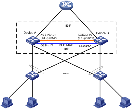
Procedure
1. Configure Device A:
# Assign member ID 1 to Device A, and bind Ten-GigabitEthernet 3/1/1 to IRF-port 2.
<DeviceA> system-view
[DeviceA] irf member 1
[DeviceA] interface ten-gigabitethernet 3/1/1
[DeviceA-Ten-GigabitEthernet3/1/1] port link-mode bridge
[DeviceA-Ten-GigabitEthernet3/1/1] quit
[DeviceA] irf-port 2
[DeviceA-irf-port2] port group interface ten-gigabitethernet 3/1/1
[DeviceA-irf-port2] quit
# Save the configuration.
[DeviceA] quit
<DeviceA> save
# Enable IRF mode.
<DeviceA> system-view
[DeviceA] chassis convert mode irf
The device will switch to IRF mode and reboot. Continue?[Y/N]:y
You are recommended to save the current running configuration and specify the configuration file for the next startup. Now save the running configuration to the
next-startup configuration file? [Y/N]:y
Please input the file name(*.cfg)[cfa0:/test.cfg]
(To leave the existing filename unchanged, press the enter key):
cfa0:/test.cfg exists, overwrite? [Y/N]:y
Validating file. Please wait...
Saved the current configuration to mainboard device successfully.
Do you want to convert the content of the next startup configuration file cfa0:/
test.cfg to make it available in IRF mode? [Y/N]:y
Now rebooting, please wait...
Device A forms a single-chassis IRF fabric after it reboots.
2. Configure Device B:
# Assign member ID 2 to Device B, and bind Ten-GigabitEthernet 3/1/3 to IRF-port 1.
<DeviceB> system-view
[DeviceB] irf member 2
[DeviceB] interface ten-gigabitethernet 3/1/3
[DeviceB-Ten-GigabitEthernet3/1/3] port link-mode bridge
[DeviceB-Ten-GigabitEthernet3/1/3] quit
[DeviceB] irf-port 1
[DeviceB-irf-port1] port group interface ten-gigabitethernet 3/1/3
[DeviceB-irf-port1] quit
# Save the configuration.
[DeviceB] quit
<DeviceB> save
# Connect the two devices as shown in Figure 15.
# Enable IRF mode on Device B.
<DeviceB> system-view
[DeviceB] chassis convert mode irf
The device will switch to IRF mode and reboot. Continue?[Y/N]:y
You are recommended to save the current running configuration and specify the configuration file for the next startup. Now save the running configuration to the
next-startup configuration file? [Y/N]:y
Please input the file name(*.cfg)[cfa0:/test.cfg]
(To leave the existing filename unchanged, press the enter key):
cfa0:/test.cfg exists, overwrite? [Y/N]:y
Validating file. Please wait...
Saved the current configuration to mainboard device successfully.
Do you want to convert the content of the next startup configuration file cfa0:/
test.cfg to make it available in IRF mode? [Y/N]:y
Now rebooting, please wait...
Device B and Device A form an IRF after Device B reboots.
3. Configure BFD MAD:
# Create VLAN 3, and add GigabitEthernet 1/4/1/1 and GigabitEthernet 2/4/1/1 to VLAN 3..
<DeviceA> system-view
[DeviceA] interface range gigabitethernet 1/4/1/1 gigabitethernet 2/4/1/1
[DeviceA-if-range] port link-mode bridge
[DeviceA-if-range] quit
[DeviceA] vlan 3
[DeviceA-vlan3] port gigabitethernet 1/4/1/1 gigabitethernet 2/4/1/1
[DeviceA-vlan3] quit
# Create VLAN-interface 3, and configure a MAD IP address for each member device on the VLAN interface.
[DeviceA] interface vlan-interface 3
[DeviceA-Vlan-interface3] mad bfd enable
[DeviceA-Vlan-interface3] mad ip address 192.168.2.1 24 member 1
[DeviceA-Vlan-interface3] mad ip address 192.168.2.2 24 member 2
[DeviceA-Vlan-interface3] quit
# Disable the spanning tree feature on GigabitEthernet 1/4/1/1 and GigabitEthernet 2/4/1/1.
[DeviceA] interface gigabitethernet 1/4/1/1
[DeviceA-GigabitEthernet1/4/1/1] undo stp enable
[DeviceA-GigabitEthernet1/4/1/1] quit
[DeviceA] interface gigabitethernet 2/4/1/1
[DeviceA-GigabitEthernet2/4/1/1] undo stp enable
Example: Enabling IRF-Connect mode in standalone mode
Network configuration
As shown in Figure 16, set up a two-member IRF fabric at the access layer of the enterprise network.
Connect the IRF member devices by using CSPC cards (except the CSPC-GE16XP4L-E, CSPC-GE24L-E, and CSPC-GP24GE8XP2L-E cards), which must be placed in IRF-Connect mode. This example shows how to enable IRF-Connect mode when both IRF member devices are operating in standalone mode.
Configure LACP MAD on the multichassis aggregation to Device C, which supports extended LACP for MAD.

Procedure
1. Configure Device A:
# Assign member ID 1 to Device A, and bind Ten-GigabitEthernet 3/1/1 to IRF-port 2.
<DeviceA> system-view
[DeviceA] irf member 1
[DeviceA] interface ten-gigabitethernet 3/1/1
[DeviceA-Ten-GigabitEthernet3/1/1] port link-mode bridge
[DeviceA-Ten-GigabitEthernet3/1/1] quit
[DeviceA] irf-port 2
[DeviceA-irf-port2] port group interface ten-gigabitethernet 3/1/1
[DeviceA-irf-port2] quit
# Enable IRF-Connect mode for the card in slot 3 of the device and for the card in slot 3 of Device B.
[DeviceA] irf-connect mode enable chassisid 1 slotid 3
Interfaces on the module in this slot will be available only for IRF connections and BFD MAD after IRF-Connect mode takes effect. Are you sure you want to enable IRF-Connect mode? [ Y/N ]:y
[DeviceA] irf-connect mode enable chassisid 2 slotid 3
Interfaces on the module in this slot will be available only for IRF connections and BFD MAD after IRF-Connect mode takes effect. Are you sure you want to enable IRF-Connect mode? [ Y/N ]:y
# Save the configuration.
[DeviceA] quit
<DeviceA> save
# Enable IRF mode.
<DeviceA> system-view
[DeviceA] chassis convert mode irf
The device will switch to IRF mode and reboot. Continue?[Y/N]:y
You are recommended to save the current running configuration and specify the configuration file for the next startup. Now save the running configuration to the
next-startup configuration file? [Y/N]:y
Please input the file name(*.cfg)[cfa0:/test.cfg]
(To leave the existing filename unchanged, press the enter key):
cfa0:/test.cfg exists, overwrite? [Y/N]:y
Validating file. Please wait...
Saved the current configuration to mainboard device successfully.
Do you want to convert the content of the next startup configuration file cfa0:/
test.cfg to make it available in IRF mode? [Y/N]:y
Now rebooting, please wait...
Device A forms a single-chassis IRF fabric after it reboots.
2. Configure Device B:
# Assign member ID 2 to Device B, and bind Ten-GigabitEthernet 3/1/1 to IRF-port 1.
<DeviceB> system-view
[DeviceB] irf member 2
[DeviceB] interface ten-gigabitethernet 3/1/1
[DeviceB-Ten-GigabitEthernet3/1/1] port link-mode bridge
[DeviceB-Ten-GigabitEthernet3/1/1] quit
[DeviceB] irf-port 1
[DeviceB-irf-port1] port group interface ten-gigabitethernet 3/1/1
[DeviceB-irf-port1] quit
# Enable IRF-Connect mode for the card in slot 3 of Device A and for the card in slot 3 of the device.
[DeviceB] irf-connect mode enable chassisid 1 slotid 3
Interfaces on the module in this slot will be available only for IRF connections and BFD MAD after IRF-Connect mode takes effect. Are you sure you want to enable IRF-Connect mode? [ Y/N ]:y
[DeviceB] irf-connect mode enable chassisid 2 slotid 3
Interfaces on the module in this slot will be available only for IRF connections and BFD MAD after IRF-Connect mode takes effect. Are you sure you want to enable IRF-Connect mode? [ Y/N ]:y
# Save the configuration.
[DeviceB] quit
<DeviceB> save
# Connect the two devices as shown in Figure 16.
# Enable IRF mode on Device B.
<DeviceB> system-view
[DeviceB] chassis convert mode irf
The device will switch to IRF mode and reboot. Continue?[Y/N]:y
You are recommended to save the current running configuration and specify the configuration file for the next startup. Now save the running configuration to the
next-startup configuration file? [Y/N]:y
Please input the file name(*.cfg)[cfa0:/test.cfg]
(To leave the existing filename unchanged, press the enter key):
cfa0:/test.cfg exists, overwrite? [Y/N]:y
Validating file. Please wait...
Saved the current configuration to mainboard device successfully.
Do you want to convert the content of the next startup configuration file cfa0:/
test.cfg to make it available in IRF mode? [Y/N]:y
Now rebooting, please wait...
3. Configure LACP MAD:
# Set the domain ID of the IRF fabric to 1.
<DeviceA> system-view
[DeviceA] irf domain 1
# Create a dynamic aggregate interface, and enable LACP MAD.
[DeviceA] interface bridge-aggregation 2
[DeviceA-Bridge-Aggregation2] link-aggregation mode dynamic
[DeviceA-Bridge-Aggregation2] mad enable
You need to assign a domain ID (range: 0-4294967295)
[Current domain is: 0]: 1
The assigned domain ID is: 1
[DeviceA-Bridge-Aggregation2] quit
# Assign Ten-GigabitEthernet 1/4/1/2 and Ten-GigabitEthernet 2/4/1/2 to the aggregate interface.
[DeviceA] interface ten-gigabitethernet 1/4/1/2
[DeviceA-Ten-GigabitEthernet1/4/1/2] port link-mode bridge
[DeviceA-Ten-GigabitEthernet1/4/1/2] port link-aggregation group 2
[DeviceA-Ten-GigabitEthernet1/4/1/2] quit
[DeviceA] interface ten-gigabitethernet 2/4/1/2
[DeviceA-Ten-GigabitEthernet2/4/1/2] port link-mode bridge
[DeviceA-Ten-GigabitEthernet2/4/1/2] port link-aggregation group 2
4. Configure Device C as the intermediate device:
|
|
CAUTION: If the intermediate device is also an IRF fabric, assign the two IRF fabrics different domain IDs for correct split detection. False detection causes IRF split. |
# Create a dynamic aggregate interface.
<DeviceC> system-view
[DeviceC] interface bridge-aggregation 2
[DeviceC-Bridge-Aggregation2] link-aggregation mode dynamic
[DeviceC-Bridge-Aggregation2] quit
# Assign Ten-GigabitEthernet 4/1/1 and Ten-GigabitEthernet 4/1/2 to the aggregate interface.
[DeviceC] interface ten-gigabitethernet 4/1/1
[DeviceC-Ten-GigabitEthernet4/1/1] port link-mode bridge
[DeviceC-Ten-GigabitEthernet4/1/1] port link-aggregation group 2
[DeviceC-Ten-GigabitEthernet4/1/1] quit
[DeviceC] interface ten-gigabitethernet 4/1/2
[DeviceC-Ten-GigabitEthernet4/1/2] port link-mode bridge
[DeviceC-Ten-GigabitEthernet4/1/2] port link-aggregation group 2
Example: Enabling IRF-Connect mode in IRF mode
Network configuration
As shown in Figure 17, a two-member IRF fabric is deployed at the access layer of the enterprise network. The IRF member devices are connected by using CSPC cards (except the CSPC-GE16XP4L-E, CSPC-GE24L-E, and CSPC-GP24GE8XP2L-E cards), which must be placed in IRF-Connect mode. This example shows how to enable IRF-Connect mode after the IRF fabric is established.
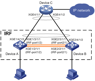
Procedure
# Enable IRF-Connect mode for the cards that have IRF physical interfaces.
<DeviceA> system-view
[DeviceA] irf-connect mode enable chassisid 1 slotid 2
Interfaces on the module in this slot will be available only for IRF connections and BFD MAD after IRF-Connect mode takes effect. Are you sure you want to enable IRF-Connect mode? [ Y/N ]:y
For the mode to take effect, please save the configuration and then reboot the module.
[DeviceA] irf-connect mode enable chassisid 2 slotid 2
Interfaces on the module in this slot will be available only for IRF connections and BFD MAD after IRF-Connect mode takes effect. Are you sure you want to enable IRF-Connect mode? [ Y/N ]:y
For the mode to take effect, please save the configuration and then reboot the module.
[DeviceA] irf-connect mode enable chassisid 1 slotid 3
Interfaces on the module in this slot will be available only for IRF connections and BFD MAD after IRF-Connect mode takes effect. Are you sure you want to enable IRF-Connect mode? [ Y/N ]:y
For the mode to take effect, please save the configuration and then reboot the module.
[DeviceA] irf-connect mode enable chassisid 2 slotid 3
Interfaces on the module in this slot will be available only for IRF connections and BFD MAD after IRF-Connect mode takes effect. Are you sure you want to enable IRF-Connect mode? [ Y/N ]:y
For the mode to take effect, please save the configuration and then reboot the module.
# Save the configuration.
[DeviceA] quit
<DeviceA> save
# Reboot the cards at the two ends of one IRF link.
|
|
CAUTION: Rebooting a card on a member device causes IRF split if all IRF physical interfaces of the device are on the card. To avoid IRF split and ensure IRF link availability, assign physical interfaces on different cards to an IRF port on a member device. |
<DeviceA> reboot chassis 2 slot 2
This command will reboot the specified slot, Continue? [Y/N]:y
Now rebooting, please wait...
<DeviceA> reboot chassis 1 slot 2
This command will reboot the specified slot, Continue? [Y/N]:y
Now rebooting, please wait...
# Reboot the cards at the two ends of the other IRF link.
<DeviceA> reboot chassis 2 slot 3
This command will reboot the specified slot, Continue? [Y/N]:y
Now rebooting, please wait...
<DeviceA> reboot chassis 1 slot 3
This command will reboot the specified slot, Continue? [Y/N]:y
Now rebooting, please wait...
Example: Configuring an IRF fabric over relay devices
Network configuration
As shown in Figure 18, set up an IRF fabric of remote member devices, which are connected by using CEPC cards through a relay device.
Configure BFD MAD on the IRF fabric and set up BFD MAD links between the member devices.
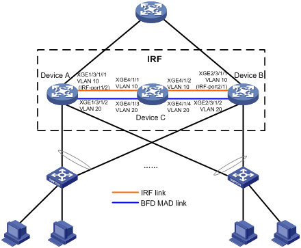
Procedure
1. Configure Device A:
# Assign member ID 1 to Device A.
<DeviceA> system-view
[DeviceA] irf member 1
# Save the running configuration to the next-startup configuration file.
[DeviceA] quit
<DeviceA> save
# Enable IRF mode.
<DeviceA> system-view
[DeviceA] chassis convert mode irf
The device will switch to IRF mode and reboot. Continue?[Y/N]:y
You are recommended to save the current running configuration and specify the configuration file for the next startup. Now save the running configuration to the
next-startup configuration file? [Y/N]:y
Please input the file name(*.cfg)[cfa0:/test.cfg]
(To leave the existing filename unchanged, press the enter key):
cfa0:/test.cfg exists, overwrite? [Y/N]:y
Validating file. Please wait...
Saved the current configuration to mainboard device successfully.
Do you want to convert the content of the next startup configuration file cfa0:/
test.cfg to make it available in IRF mode? [Y/N]:y
Now rebooting, please wait...
Device A forms a one-chassis IRF fabric after it reboots.
# Bind Ten-GigabitEthernet 1/3/1/1 to IRF-port 1/2, and specify VLAN 10 as the IRF packet VLAN for the IRF link.
<DeviceA> system-view
[DeviceA] interface ten-gigabitethernet 1/3/1/1
[DeviceA-Ten-GigabitEthernet1/3/1/1] port link-mode bridge
[DeviceA-Ten-GigabitEthernet1/3/1/1] shutdown
[DeviceA-Ten-GigabitEthernet1/3/1/1] quit
[DeviceA] irf-port 1/2
[DeviceA-irf-port1/2] port group interface ten-gigabitethernet 1/3/1/1 vlan 10
[DeviceA-irf-port1/2] quit
# Bring up Ten-GigabitEthernet 1/3/1/1.
[DeviceA] interface ten-gigabitethernet 1/3/1/1
[DeviceA-Ten-GigabitEthernet1/3/1/1] undo shutdown
[DeviceA-Ten-GigabitEthernet1/3/1/1] quit
# Save the running configuration to the next-startup configuration file.
[DeviceA] quit
<DeviceA> save
# Reboot the card that holds the IRF physical interface.
<DeviceA> reboot chassis 1 slot 3
This command will reboot the specified slot, Continue? [Y/N]:y
Now rebooting, please wait...
# Activate the IRF port configuration after the state of the card recovers to Normal.
<DeviceA> system-view
[DeviceA] irf-port-configuration active
2. Configure Device B:
# Assign member ID 2 to Device B.
<DeviceB> system-view
[DeviceB] irf member 2
# Save the running configuration to the next-startup configuration file.
[DeviceB] quit
<DeviceB> save
# Enable IRF mode.
<DeviceB> system-view
[DeviceB] chassis convert mode irf
The device will switch to IRF mode and reboot. Continue?[Y/N]:y
You are recommended to save the current running configuration and specify the configuration file for the next startup. Now save the running configuration to the
next-startup configuration file? [Y/N]:y
Please input the file name(*.cfg)[cfa0:/test.cfg]
(To leave the existing filename unchanged, press the enter key):
cfa0:/test.cfg exists, overwrite? [Y/N]:y
Validating file. Please wait...
Saved the current configuration to mainboard device successfully.
Do you want to convert the content of the next startup configuration file cfa0:/
test.cfg to make it available in IRF mode? [Y/N]:y
Now rebooting, please wait...
# Bind Ten-GigabitEthernet 2/3/1/1 to IRF-port 2/1. Specify VLAN 10 as the IRF packet VLAN for it. You must assign the physical interface the same IRF packet VLAN as its peer interface.
<DeviceB> system-view
[DeviceB] interface ten-gigabitethernet 2/3/1/1
[DeviceB-Ten-GigabitEthernet2/3/1/1]port link-mode bridge
[DeviceB-Ten-GigabitEthernet2/3/1/1] shutdown
[DeviceB-Ten-GigabitEthernet2/3/1/1] quit
[DeviceB] irf-port 2/1
[DeviceB-irf-port2/1] port group interface ten-gigabitethernet 2/3/1/1 vlan 10
[DeviceB-irf-port2/1] quit
# Bring up Ten-GigabitEthernet 2/3/1/1.
[DeviceB] interface ten-gigabitethernet 2/3/1/1
[DeviceB-Ten-GigabitEthernet2/3/1/1] undo shutdown
[DeviceB-Ten-GigabitEthernet2/3/1/1] quit
# Save the running configuration to the next-startup configuration file.
[DeviceB] quit
<DeviceB> save
# Reboot the card that holds the IRF physical interface.
<DeviceB> reboot Chassis 2 slot 3
This command will reboot the specified slot, Continue? [Y/N]:y
Now rebooting, please wait...
# Activate the IRF port configuration after the state of the card recovers to Normal.
<DeviceB> system-view
[DeviceB] irf-port-configuration active
3. Configure Device C:
# Create VLAN 10.
<DeviceC> system-view
[DeviceC] vlan 10
# Change the link mode of Ten-GigabitEthernet 4/1/1 and Ten-GigabitEthernet 4/1/2 to bridge, remove the ports from VLAN 1, assign them to VLAN 10, and disable spanning tree on them.
[DeviceC] interface ten-gigabitethernet 4/1/1
[DeviceC-Ten-GigabitEthernet4/1/1] port link-mode bridge
[DeviceC-Ten-GigabitEthernet4/1/1] port link-type trunk
[DeviceC-Ten-GigabitEthernet4/1/1] undo port trunk permit vlan 1
[DeviceC-Ten-GigabitEthernet4/1/1] port trunk permit vlan 10
[DeviceC-Ten-GigabitEthernet4/1/1] undo stp enable
[DeviceC-Ten-GigabitEthernet4/1/1] quit
[DeviceC] interface ten-gigabitethernet 4/1/2
[DeviceC-Ten-GigabitEthernet4/1/2] port link-mode bridge
[DeviceC-Ten-GigabitEthernet4/1/2] port link-type trunk
[DeviceC-Ten-GigabitEthernet4/1/2] undo port trunk permit vlan 1
[DeviceC-Ten-GigabitEthernet4/1/2] port trunk permit vlan 10
[DeviceC-Ten-GigabitEthernet4/1/2] undo stp enable
[DeviceC-Ten-GigabitEthernet4/1/2] quit
IRF merge occurs after Device A and Device B exchange IRF hello packets. The device that has failed master election automatically reboots to form an IRF fabric with the other device.
4. Configure BFD MAD on the IRF fabric:
# Create VLAN 20, add Ten-GigabitEthernet 1/3/1/2 on Device A and Ten-GigabitEthernet 2/3/1/2 on Device B to VLAN 20, and configure the ports as BFD MAD dedicated ports.
<DeviceA> system-view
[DeviceA] vlan 20
[DeviceA-vlan20] quit
[DeviceA] interface ten-gigabitethernet 1/3/1/2
[DeviceA-Ten-GigabitEthernet1/3/1/2] port link-mode bridge
[DeviceA-Ten-GigabitEthernet1/3/1/2] port link-type trunk
[DeviceA-Ten-GigabitEthernet1/3/1/2] undo port trunk permit vlan 1
[DeviceA-Ten-GigabitEthernet1/3/1/2] port trunk permit vlan 20
[DeviceA-Ten-GigabitEthernet1/3/1/2] undo stp enable
[DeviceA-Ten-GigabitEthernet1/3/1/2] mad bfd dedicated
The interface will drop all packets except BFD MAD packets. Are you sure you want to continue? [Y/N]:y
[DeviceA-Ten-GigabitEthernet1/3/1/2] quit
[DeviceA] interface ten-gigabitethernet 2/3/1/2
[DeviceA-Ten-GigabitEthernet2/3/1/2] port link-mode bridge
[DeviceA-Ten-GigabitEthernet2/3/1/2] port link-type trunk
[DeviceA-Ten-GigabitEthernet2/3/1/2] undo port trunk permit vlan 1
[DeviceA-Ten-GigabitEthernet2/3/1/2] port trunk permit vlan 20
[DeviceA-Ten-GigabitEthernet2/3/1/2] undo stp enable
[DeviceA-Ten-GigabitEthernet2/3/1/2] mad bfd dedicated
The interface will drop all packets except BFD MAD packets. Are you sure you want to continue? [Y/N]:y
[DeviceA-Ten-GigabitEthernet2/3/1/2] quit
# Create VLAN-interface 20, and configure a MAD IP address for each member device on the VLAN interface.
[DeviceA] interface vlan-interface 20
[DeviceA-Vlan-interface20] mad bfd enable
[DeviceA-Vlan-interface20] mad ip address 192.168.2.1 24 member 1
[DeviceA-Vlan-interface20] mad ip address 192.168.2.2 24 member 2
[DeviceA-Vlan-interface20] quit
5. Configure settings for BFD MAD on Device C:
# Create VLAN 20.
<DeviceC> system-view
[DeviceC] vlan 20
# Set the link mode of Ten-GigabitEthernet 4/1/3 and Ten-GigabitEthernet 4/1/4 to bridge, remove the ports from VLAN 1, assign them to VLAN 20, and disable spanning tree on them.
[DeviceC] interface ten-gigabitethernet 4/1/3
[DeviceC-Ten-GigabitEthernet4/1/3] port link-mode bridge
[DeviceC-Ten-GigabitEthernet4/1/3] port link-type trunk
[DeviceC-Ten-GigabitEthernet4/1/3] undo port trunk permit vlan 1
[DeviceC-Ten-GigabitEthernet4/1/3] port trunk permit vlan 20
[DeviceC-Ten-GigabitEthernet4/1/3] undo stp enable
[DeviceC-Ten-GigabitEthernet4/1/3] quit
[DeviceC] interface ten-gigabitethernet 4/1/4
[DeviceC-Ten-GigabitEthernet4/1/4] port link-mode bridge
[DeviceC-Ten-GigabitEthernet4/1/4] port link-type trunk
[DeviceC-Ten-GigabitEthernet4/1/4] undo port trunk permit vlan 1
[DeviceC-Ten-GigabitEthernet4/1/4] port trunk permit vlan 20
[DeviceC-Ten-GigabitEthernet4/1/4] undo stp enable
[DeviceC-Ten-GigabitEthernet4/1/4] quit
Example: Restoring standalone mode
Network configuration
Break the IRF fabric in Figure 19, and change the operating mode of Device A and Device B from IRF to standalone.
Restrictions and guidelines
If the Layer 2 ports of a VLAN interface are distributed on both member devices, the restoration operation might introduce IP collision risks. The VLAN interface might be up on both devices. In this situation, modify the IP address of the VLAN interface on one device.
Procedure
1. Identify the master.
<IRF> display irf
MemberID Slot Role Priority CPU-Mac Description
*+1 0 Master 1 00e0-fc0f-8c01 DeviceA
1 3 Standby 1 00e0-fc0f-8c02 DeviceA
2 0 Standby 1 00e0-fc0f-15e1 DeviceB
2 3 Standby 1 00e0-fc0f-15e2 DeviceB
--------------------------------------------------
* indicates the device is the master.
+ indicates the device through which the user logs in.
The Bridge MAC of the IRF is: 0000-fc00-313e
Auto upgrade : no
Mac persistent : always
Domain ID : 1
Auto merge : no
The output shows that Device A is the master.
2. Shut down IRF physical interfaces to disconnect all IRF links. In this example, shut down Ten-GigabitEthernet 1/3/1/1.
<IRF> system-view
[IRF] interface ten-gigabitethernet 1/3/1/1
[IRF-Ten-GigabitEthernet1/3/1/1] shutdown
[IRF-Ten-GigabitEthernet1/3/1/1] quit
3. Remove Ten-GigabitEthernet 1/3/1/1 from IRF port 1/2.
[IRF] irf-port 1/2
[IRF-irf-port1/2] undo port group interface ten-gigabitethernet 1/3/1/1
[IRF-irf-port1/2] quit
4. Save the configuration.
[IRF] save
The current configuration will be written to the device. Are you sure? [Y/N]:y
Please input the file name(*.cfg)[flash:/startup.cfg]
(To leave the existing filename unchanged, press the enter key):
flash:/startup.cfg exists, overwrite? [Y/N]:y
Validating file. Please wait.....................................
The current configuration is saved to the active main board successfully.
Configuration is saved to device successfully.
5. Change the operating mode of Device A to standalone.
[IRF] undo chassis convert mode
The device will switch to stand-alone mode and reboot. Continue?[Y/N]:
Before pressing ENTER you must choose 'YES' or 'NO'[Y/N]:y
You are recommended to save the current running configuration and specify the configuration file for the next startup. Now save the running configuration to the
next-startup configuration file? [Y/N]:y
Please input the file name(*.cfg)[cfa0:/startup.cfg]
(To leave the existing filename unchanged, press the enter key):
cfa0:/startup.cfg exists, overwrite? [Y/N]:y
Validating file. Please wait...
Saved the current configuration to mainboard device successfully.
Do you want to convert the content of the next startup configuration file cfa0:/
startup.cfg to make it available in stand-alone mode? [Y/N]:y
Now rebooting, please wait...
Device A automatically reboots to complete the operating mode change.
6. Log in to Device B and shut down Ten-GigabitEthernet 2/3/1/1.
<IRF> system-view
[IRF] interface ten-gigabitethernet 2/3/1/1
[IRF-Ten-Gigabitethernet2/3/1/1] shutdown
[IRF-Ten-Gigabitethernet2/3/1/1] quit
7. Remove Ten-GigabitEthernet 2/3/1/1 from IRF port 2/1.
[IRF] irf-port 2/1
[IRF-irf-port2/1] undo port group interface ten-gigabitethernet 2/3/1/1
[IRF-irf-port2/1] quit
8. Save the configuration.
[IRF] save
The current configuration will be written to the device. Are you sure? [Y/N]:y
Please input the file name(*.cfg)[flash:/startup.cfg]
(To leave the existing filename unchanged, press the enter key):
flash:/startup.cfg exists, overwrite? [Y/N]:y
Validating file. Please wait.....................................
The current configuration is saved to the active main board successfully.
Configuration is saved to device successfully.
9. Change the operating mode of Device B to standalone.
[IRF] undo chassis convert mode
The device will switch to stand-alone mode and reboot. Continue?[Y/N]:
Before pressing ENTER you must choose 'YES' or 'NO'[Y/N]:y
You are recommended to save the current running configuration and specify the configuration file for the next startup. Now save the running configuration to the
next-startup configuration file? [Y/N]:y
Please input the file name(*.cfg)[cfa0:/startup.cfg]
(To leave the existing filename unchanged, press the enter key):
cfa0:/startup.cfg exists, overwrite? [Y/N]:y
Validating file. Please wait...
Saved the current configuration to mainboard device successfully.
Do you want to convert the content of the next startup configuration file cfa0:/
startup.cfg to make it available in stand-alone mode? [Y/N]:y
Now rebooting, please wait...
Device B automatically reboots to complete the operating mode change.
