- Table of Contents
- Related Documents
-
| Title | Size | Download |
|---|---|---|
| 01-VXLAN configuration | 722.35 KB |
VXLAN tunnel establishment and assignment
Assignment of traffic to VXLANs
Configuring basic VXLAN features
Setting the forwarding mode for VXLANs
Assigning a VXLAN tunnel to a VXLAN
Mapping an Ethernet service instance to a VSI
Enabling VXLAN local MAC change logging
Configuring static remote-MAC address entries
Enabling remote-MAC address learning
Configuring a multicast-mode VXLAN
Confining unknown-unicast floods to the local site
Confining the flood traffic of an Ethernet service instance
Configuring the destination UDP port number of VXLAN packets
Configuring VXLAN packet check
Enabling ARP flood suppression
Disabling remote ARP learning for VXLANs
Configuring VXLAN packet statistics
Enabling packet statistics for a VSI
Enabling packet statistics for an Ethernet service instance
Setting the VXLAN hardware resource allocation mode
Displaying and maintaining VXLANs
Unicast-mode VXLAN configuration example
Multicast-mode VXLAN configuration example
VXLAN IP gateways separated from VTEPs
Centralized VXLAN IP gateway deployment
Centralized VXLAN IP gateway group deployment
Configuration restrictions and guidelines
Configuring a centralized VXLAN IP gateway on a VTEP
Configuring a centralized VXLAN IP gateway group
Specifying a VTEP group as the gateway for an access layer VTEP
Enabling packet statistics for VSI interfaces
Displaying and maintaining VXLAN IP gateway
VXLAN IP gateway configuration examples
Centralized VXLAN IP gateway configuration example
Centralized VXLAN IP gateway group configuration example
Configuring the VTEP as an OVSDB VTEP
OVSDB VTEP configuration task list
Setting up an OVSDB connection to a controller
Configuration restrictions and guidelines
Configuring active SSL connection settings
Configuring passive SSL connection settings
Configuring active TCP connection settings
Configuring passive TCP connection settings
Enabling the OVSDB VTEP service
Specifying a global source address for VXLAN tunnels
Enabling flood proxy on multicast VXLAN tunnels
OVSDB VTEP configuration examples
Unicast-mode VXLAN configuration example
Flood proxy VXLAN configuration example
VXLAN overview
Virtual eXtensible LAN (VXLAN) is a MAC-in-UDP technology that provides Layer 2 connectivity between distant network sites across an IP network. VXLAN is typically used in data centers for multitenant services.
VXLAN provides the following benefits:
· Support for more virtual switched domains than VLANs—Each VXLAN is uniquely identified by a 24-bit VXLAN ID. The total number of VXLANs can reach 16777216 (224). This specification makes VXLAN a better choice than 802.1Q VLAN to isolate traffic for VMs.
· Easy deployment and maintenance—VXLAN requires deployment only on the edge devices of the transport network. Devices in the transport network perform typical Layer 3 forwarding.
Hardware compatibility
Only FC, FE, and FX cards support VXLANs.
FC cards cannot provide VXLAN IP gateway services.
An FE or FX card cannot connect to a user site if it acts as a centralized VXLAN IP gateway.
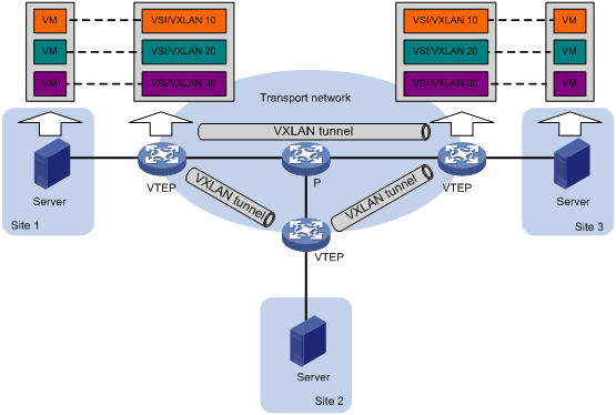
VXLAN network model
As shown in Figure 1, the transport edge devices assign VMs to different VXLANs, and then forward traffic between sites for VMs by using VXLAN tunnels.
The transport edge devices are VXLAN tunnel endpoints (VTEP). They can be servers that host VMs or independent network devices.
An H3C VTEP uses VSIs and VXLAN tunnels to provide VXLAN services.
· VSI—A virtual switching instance is a virtual Layer 2 switched domain. Each VSI provides switching services only for one VXLAN. VSIs learn MAC addresses and forward frames independently of one another. VMs in different sites have Layer 2 connectivity if they are in the same VXLAN.
· VXLAN tunnel—Logical point-to-point tunnels between VTEPs over the transport network. Each VXLAN tunnel can trunk multiple VXLANs.
VTEPs encapsulate VXLAN traffic in the VXLAN, outer UDP, and outer IP headers. The devices in the transport network forward VXLAN traffic only based on the outer IP header.
Figure 1 VXLAN network model
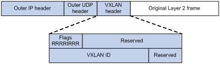
VXLAN packet format
As shown in Figure 2, a VTEP encapsulates a frame in the following headers:
· 8-byte VXLAN header—VXLAN information for the frame.
? Flags—If the I bit is 1, the VXLAN ID is valid. If the I bit is 0, the VXLAN ID is invalid. All other bits are reserved and set to 0.
? 24-bit VXLAN ID—Identifies the VXLAN of the frame. It is also called the virtual network identifier (VNI).
· 8-byte outer UDP header for VXLAN—The default VXLAN UDP port number is 4789.
· 20-byte outer IP header—Valid addresses of VTEPs or VXLAN multicast groups on the transport network. Devices in the transport network forward VXLAN packets based on the outer IP header.
Figure 2 VXLAN packet format
Working mechanisms
The VTEP uses the following process to forward an inter-site frame:
1. Assigns the frame to its matching VXLAN if the frame is sent between sites.
2. Performs MAC learning on the VXLAN's VSI.
3. Forwards the frame.
This section describes this process in detail. For intra-site frames in a VSI, the system performs typical Layer 2 forwarding and processes 802.1Q VLAN tags, as described in "Access modes of VSIs."
VXLAN tunnel establishment and assignment
To provide Layer 2 connectivity for a VXLAN between two sites, you must create a VXLAN tunnel between the sites and assign the tunnel to the VXLAN.
Assignment of traffic to VXLANs
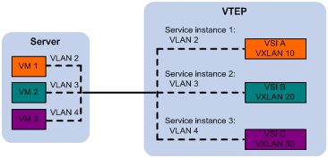
Traffic from the local site to a remote site
The VTEP uses an Ethernet service instance to match a list of VLANs on a site-facing interface. The VTEP assigns customer traffic from the VLANs to a VXLAN by mapping the Ethernet service instance to a VSI. An Ethernet service instance is identical to an attachment circuit (AC) in L2VPN.
As shown in Figure 3, Ethernet service instance 1 matches VLAN 2 and is mapped to VSI A (VXLAN 10). When a frame from VLAN 2 arrives, the VTEP assigns the frame to VXLAN 10, and looks up VSI A's MAC address table for the outgoing interface.
Figure 3 Identifying traffic from the local site
Traffic from a remote site to the local site
When a frame arrives at a VXLAN tunnel, the VTEP uses the VXLAN ID in the frame to identify its VXLAN.
MAC learning
The VTEP performs source MAC learning on the VSI as a Layer 2 switch.
· For traffic from the local site to the remote site, the VTEP learns the source MAC address before VXLAN encapsulation.
· For traffic from the remote site to the local site, the VTEP learns the source MAC address after removing the VXLAN header.
A VSI's MAC address table includes the following types of MAC address entries:
· Local MAC—Dynamic MAC entries learned from the local site. The outgoing interfaces are site-facing interfaces on which the MAC addresses are learned. VXLAN does not support manual local MAC entries.
· Remote MAC—MAC entries learned from a remote site, including static, dynamic, and OpenFlow MAC entries. The outgoing interfaces for the MAC addresses are VXLAN tunnel interfaces.
? Static—Manually added MAC entries.
? Dynamic—MAC entries learned in the data plane from incoming traffic on VXLAN tunnels. The learned MAC addresses are contained in the inner Ethernet header.
? OpenFlow—MAC entries issued by a remote controller through OpenFlow.
For a remote address, the manual static entry has higher priority than the dynamic entry.
Traffic forwarding
The device performs Layer 2 or Layer 3 forwarding for VXLANs depending on your configuration.
· In Layer 3 forwarding mode, the device uses the ARP table to forward traffic for VXLANs.
· In Layer 2 forwarding mode, the device uses the MAC address table to forward traffic for VXLANs.
Use Layer 3 forwarding mode if you want to use the device as a VXLAN IP gateway.
This section describes the Layer 2 forwarding processes. For information about Layer 3 forwarding, see "Configuring a centralized VXLAN IP gateway on a VTEP."
A VTEP uses the following processes to forward traffic at Layer 2:
· Unicast process—Applies to destination-known unicast traffic.
· Flood process—Applies to multicast, broadcast, and unknown unicast traffic.
When the VTEP forwards VXLAN traffic, it processes the 802.1q tag in the inner Ethernet header depending on the VSI access mode (VLAN or Ethernet mode). In VLAN access mode, sites can use different VLANs to provide the same service. For more information, see "Access modes of VSIs."
Unicast
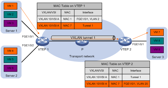
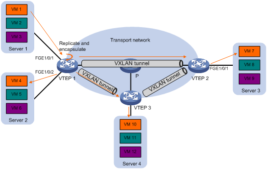
The following process (see Figure 4) applies to a known unicast frame between sites:
1. The source VTEP encapsulates the Ethernet frame in the VXLAN/UDP/IP header.
In the outer IP header, the source IP address is the source VTEP's VXLAN tunnel source IP address. The destination IP address is the VXLAN tunnel destination IP address.
2. The source VTEP forwards the encapsulated packet out of the outgoing VXLAN tunnel interface found in the VSI's MAC address table.
3. The intermediate transport devices (P devices) forward the frame to the destination VTEP by using the outer IP header.
4. The destination VTEP removes the headers on top of the inner Ethernet frame. It then performs MAC address table lookup in the VXLAN's VSI to forward the frame out of the matching outgoing interface.
Flood
The VTEP floods a broadcast, multicast, or unknown unicast frame to all site-facing interfaces and VXLAN tunnels in the VXLAN, except for the incoming interface.
VXLAN supports the following modes for flood traffic:
· Unicast mode—Also called head-end replication. The source VTEP replicates the flood frame, and then sends one replica to the destination IP address of each VXLAN tunnel in the VXLAN. See Figure 5.
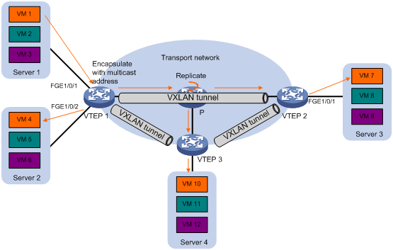
· Multicast mode—Also called tandem replication. The source VTEP sends the flood frame in a multicast VXLAN packet destined for a multicast group address. Transport network devices replicate and forward the packet to remote VTEPs based on their multicast forwarding entries. See Figure 6.
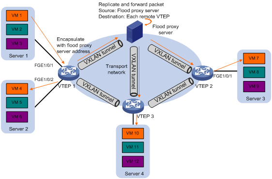
· Flood proxy mode—The source VTEP sends the flood frame in a VXLAN packet over a VXLAN tunnel to a flood proxy server. The flood proxy server replicates and forwards the packet to each remote VTEP through its VXLAN tunnels. See Figure 7.
The flood proxy mode applies to VXLANs that have many sites. This mode reduces flood traffic in the transport network without using a multicast protocol. To use a flood proxy server, you must set up a VXLAN tunnel to the server on each VTEP.
The flood proxy mode is typically used in SDN transport networks that have a flood proxy server. For VTEPs to forward packets based on the MAC address table issued by an SDN controller, you must disable remote-MAC address learning by using the vxlan tunnel mac-learning disable command.
Each destination VTEP floods the inner Ethernet frame to all the site-facing interfaces in the VXLAN. To avoid loops, the destination VTEPs do not flood the frame to VXLAN tunnels.
Access modes of VSIs
The access mode of a VSI determines how the VTEP processes the 802.1Q VLAN tags in the Ethernet frames.
· VLAN access mode—Ethernet frames received from or sent to the local site must contain 802.1Q VLAN tags.
? For an Ethernet frame received from the local site, the VTEP removes all its 802.1Q VLAN tags before forwarding the frame.
? For an Ethernet frame destined for the local site, the VTEP adds 802.1Q VLAN tags to the frame before forwarding the frame.
In VLAN access mode, VXLAN packets sent between sites do not contain 802.1Q VLAN tags. You can use different 802.1Q VLANs to provide the same service in different sites.
· Ethernet access mode—The VTEP does not process the 802.1Q VLAN tags of Ethernet frames received from or sent to the local site.
? For an Ethernet frame received from the local site, the VTEP forwards the frame with the 802.1Q VLAN tags intact.
? For an Ethernet frame destined for the local site, the VTEP forwards the frame without adding 802.1Q VLAN tags.
In Ethernet access mode, VXLAN packets sent between VXLAN sites contain 802.1Q VLAN tags. You must use the same VLAN to provide the same service between sites.
ARP flood suppression
ARP flood suppression reduces ARP request broadcasts by enabling the VTEP to reply to ARP requests on behalf of VMs.
As shown in Figure 8, this feature snoops ARP packets to populate the ARP flood suppression table with local and remote MAC addresses. If an ARP request has a matching entry, the VTEP replies to the request on behalf of the VM. If no match is found, the VTEP floods the request to both local and remote sites.
Figure 8 ARP flood suppression
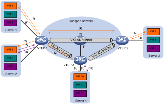
ARP flood suppression uses the following workflow:
1. VM 1 sends an ARP request to obtain the MAC address of VM 7.
2. VTEP 1 creates a suppression entry for VM 1, and floods the ARP request in the VXLAN.
3. VTEP 2 and VTEP 3 de-encapsulate the ARP request. The VTEPs create a suppression entry for VM 1, and broadcast the request in the local site.
4. VM 7 sends an ARP reply.
5. VTEP 2 creates a suppression entry for VM 7 and forwards the ARP reply to VTEP 1.
6. VTEP 1 de-encapsulates the ARP reply, creates a suppression entry for VM 7, and forwards the ARP reply to VM 1.
7. VM 4 sends an ARP request to obtain the MAC address of VM 1 or VM 7.
8. VTEP 1 creates a suppression entry for VM 4 and replies to the ARP request.
9. VM 10 sends an ARP request to obtain the MAC address of VM 1.
10. VTEP 3 creates a suppression entry for VM 10 and replies to the ARP request.
VXLAN IP gateways
A VXLAN IP gateway provides Layer 3 forwarding services for VMs in VXLANs. A VXLAN IP gateway can be an independent device or be collocated with a VTEP. For more information about VXLAN IP gateway placement, see "Configuring VXLAN IP gateways."
Protocols and standards
IETF draft, draft-mahalingam-dutt-dcops-vxlan-04
Configuring basic VXLAN features
Configuration restrictions
When you use VXLAN in conjunction with VLAN mapping, TRILL, and MPLS, follow these restrictions:
· Do not use the rewrite inbound tag or rewrite outbound tag command together with VLAN mapping, TRILL, or MPLS.
· The following settings are mutually exclusive on the interfaces associated with the same chip:
? Ethernet service instance of which the match criterion contains a VLAN ID range.
? VLAN mapping.
To view the mappings between interfaces and chips, use the debug port mapping command in probe view.
· The following settings are mutually exclusive on an interface:
? Ethernet service instance that matches only inconsecutive VLAN IDs.
? VLAN mapping.
VXLAN configuration task list
|
Tasks at a glance |
Remarks |
|
(Required.) Setting the forwarding mode for VXLANs |
N/A |
|
(Required.) Creating a VXLAN on a VSI |
N/A |
|
(Required.) Configuring a VXLAN tunnel |
N/A |
|
(Required.) Assigning a VXLAN tunnel to a VXLAN |
To extend a VXLAN to remote sites, you must assign VXLAN tunnels to the VXLAN. |
|
(Required.) Mapping an Ethernet service instance to a VSI |
Perform this task to assign customer traffic to VXLANs. |
|
(Optional.) Managing MAC address entries |
You can add static remote MAC addresses. When network attacks occur, disable remote-MAC address learning to prevent the device from learning incorrect remote MAC addresses. |
|
(Optional.) Confining unknown-unicast floods to the local site |
Perform this task to suppress unknown-unicast floods to the transport network. |
|
(Optional.) Confining the flood traffic of an Ethernet service instance |
Perform this task to reduce flood traffic between the Ethernet service instances of a VSI. |
|
(Optional.) Configuring the destination UDP port number of VXLAN packets |
N/A |
|
(Optional.) Configuring VXLAN packet check |
Perform this task to check incoming VXLAN packets, including the following items: · UDP checksum. · 802.1Q VLAN tags in the inner Ethernet header. |
|
(Optional.) Enabling ARP flood suppression |
N/A |
|
(Optional.) Disabling remote ARP learning for VXLANs |
N/A |
|
(Optional.) Configuring VXLAN packet statistics |
N/A |
|
(Optional.) Setting the VXLAN hardware resource allocation mode |
N/A |
Prerequisites
Before you can configure VXLANs, you must perform the following tasks:
· Configure a routing protocol on the devices in the transport network to make sure the VTEPs can reach one another.
· Set the system operation mode on VTEPs:
a. Set the system operating mode to standard by using the system-working-mode standard command. For more information about setting the system operating mode, see device management in Fundamentals Configuration Guide.
b. Save the configuration.
c. Delete the binary .mdb next-startup configuration file.
d. Reboot the device.
Setting the forwarding mode for VXLANs
|
Step |
Command |
Remarks |
|
1. Enter system view. |
system-view |
N/A |
|
2. Enable Layer 2 or Layer 3 forwarding for VXLANs. |
·
Enable Layer 2
forwarding: ·
Enable Layer 3 forwarding: |
By default, Layer 3 forwarding is enabled for VXLANs. If the VTEP is not a VXLAN IP gateway, enable Layer 2 forwarding for VXLANs. If the VTEP is a VXLAN IP gateway, enable Layer 3 forwarding for VXLANs. For more information about VXLAN IP gateways, see "Configuring VXLAN IP gateways." You must delete all VSIs, VSI interfaces, and VXLAN tunnel interfaces before you can change the forwarding mode. To reduce the workload, plan the VXLAN network deployment first and configure the forwarding mode before other VXLAN settings. |
Creating a VXLAN on a VSI
|
Command |
Remarks |
|
|
1. Enter system view. |
system-view |
N/A |
|
2. Enable L2VPN. |
l2vpn enable |
By default, L2VPN is disabled. |
|
3. Create a VSI and enter VSI view. |
vsi vsi-name |
By default, no VSIs are created. |
|
4. (Optional.) Configure a VSI description. |
description text |
By default, a VSI does not have description. |
|
5. Enable the VSI. |
undo shutdown |
By default, a VSI is enabled. |
|
6. Create a VXLAN and enter VXLAN view. |
vxlan vxlan-id |
By default, no VXLANs are created. You can create only one VXLAN on a VSI. The VXLAN ID must be unique for each VSI. |
Configuring a VXLAN tunnel
For two sites to communicate through VXLAN, you must manually configure a VXLAN tunnel between the sites.
This task provides basic VXLAN tunnel configuration. For more information about tunnel configuration and commands, see Layer 3—IP Services Configuration Guide and Layer 3—IP Services Command Reference.
To avoid traffic forwarding failure, do not configure an interface that hosts ACs as a traffic outgoing interface for VXLAN tunnels.
To configure a VXLAN tunnel:
|
Step |
Command |
Remarks |
|
1. Enter system view. |
system-view |
N/A |
|
2. Specify a global source address for VXLAN tunnels. |
tunnel global source-address ip-address |
By default, no global source address is specified for VXLAN tunnels. A VXLAN tunnel uses the global source address if you do not specify a source interface or source address for the tunnel. |
|
3. Create a VXLAN tunnel interface and enter tunnel interface view. |
interface tunnel tunnel-number mode vxlan |
By default, no tunnel interfaces exist. The endpoints of a tunnel must use the same tunnel mode. ECMP is supported only by the first 512 VXLAN tunnels created by using this command. |
|
4. Specify a source IP address or source interface for the tunnel. |
source { ipv4-address | interface-type interface-number } |
By default, no source IP address or source interface is specified for a tunnel. This step specifies the source IP address in the outer IP header of tunneled VXLAN packets. If an interface is specified, its primary IP address is used. For a multicast-mode VXLAN, the source IP address cannot be the address of a loopback interface, and the source interface cannot be a loopback interface. |
|
5. Specify a destination IP address for the tunnel. |
destination ipv4-address |
By default, no destination IP address is specified for a tunnel. Specify the remote VTEP's IP address. This IP address will be the destination IP address in the outer IP header of tunneled VXLAN packets. |
Assigning a VXLAN tunnel to a VXLAN
To provide Layer 2 connectivity for a VXLAN between two sites, you must assign the VXLAN tunnel between the sites to the VXLAN.
You can assign multiple VXLAN tunnels to a VXLAN, and configure a VXLAN tunnel to trunk multiple VXLANs. For a unicast-mode VXLAN, the system floods unknown unicast, multicast, and broadcast traffic to each tunnel associated with the VXLAN.
To assign a VXLAN tunnel to a VXLAN:
|
Step |
Command |
Remarks |
|
1. Enter system view. |
system-view |
N/A |
|
2. Enter VSI view. |
vsi vsi-name |
N/A |
|
3. Enter VXLAN view. |
vxlan vxlan-id |
N/A |
|
4. Assign a VXLAN tunnel to the VXLAN. |
tunnel tunnel-number [ flooding-proxy ] |
By default, a VXLAN does not contain any VXLAN tunnels. For full Layer 2 connectivity in the VXLAN, make sure the VXLAN contains the VXLAN tunnel between each pair of sites in the VXLAN. |
Mapping an Ethernet service instance to a VSI
An Ethernet service instance matches a list of VLANs on a site-facing interface. The VTEP assigns customer traffic from the VLANs to a VXLAN by mapping the Ethernet service instance to a VSI.
When you configure Ethernet service instances on an interface, follow these guidelines:
· The match criterion in each Ethernet service instance on an interface must be unique. For example, you cannot configure the encapsulation untagged command in one Ethernet service instance if another Ethernet service instance already contains this command. You cannot use the encapsulation s-vid vlan-id-list command to specify the same 802.1Q VLAN ID for any two Ethernet service instances on the interface.
· An Ethernet service instance can contain only one match criterion. To change the match criterion to another one, you must remove the original criterion first. When you remove the match criterion in an Ethernet service instance, the mapping between the service instance and the VSI is removed automatically.
· To forward the multicast traffic from a VLAN on the interface, make sure an Ethernet service instance contains the VLAN ID. The interface cannot forward a multicast packet that does not match any Ethernet service instance.
· You must create a VLAN interface for each VLAN that matches an Ethernet service instance if ARP flood suppression is enabled. You do not need to assign IP addresses to the VLAN interfaces. However, you must make sure the VLANs each contain a minimum of one up physical interface.
To map an Ethernet service instance to a VSI:
|
Step |
Command |
Remarks |
|
1. Enter system view. |
system-view |
N/A |
|
2. Enter Layer 2 Ethernet interface view or Layer 2 aggregate interface view. |
· interface interface-type interface-number · interface bridge-aggregation interface-number |
N/A |
|
3. Create an Ethernet service instance and enter Ethernet service instance view. |
service-instance instance-id |
By default, no Ethernet service instances exist. |
|
4. Configure a frame match criterion. |
·
Match any frames: ·
Match untagged frames: ·
Match frames tagged with the specified outer 802.1Q
VLAN IDs: ·
Match frames tagged with the specified outer
and inner 802.1Q VLAN IDs: |
By default, an Ethernet service instance does not contain a frame match criterion. To match frames from a VLAN correctly, make sure you have created the VLAN and assigned the interface to the VLAN. |
|
5. (Optional.) Configure the VLAN tag processing rule for incoming traffic. |
rewrite inbound tag { nest { c-vid vlan-id | s-vid vlan-id [ c-vid vlan-id ] } | remark { { 1-to-1 | 2-to-1 } { c-vid vlan-id | s-vid vlan-id } | { 1-to-2 | 2-to-2 } { s-vid vlan-id c-vid vlan-id } } | strip { c-vid | s-vid [ c-vid ] } } [ symmetric ] |
By default, VLAN tags of incoming traffic are not processed. |
|
6. (Optional.) Configure the VLAN tag processing rule for outgoing traffic. |
rewrite outbound tag { nest { c-vid vlan-id | s-vid vlan-id [ c-vid vlan-id ] } | remark { { 1-to-1 | 2-to-1 } { c-vid vlan-id | s-vid vlan-id } | { 1-to-2 | 2-to-2 } { s-vid vlan-id c-vid vlan-id } } | strip { c-vid | s-vid [ c-vid ] } } |
By default, VLAN tags of outgoing traffic are not processed. |
|
7. Map the Ethernet service instance to a VSI. |
xconnect vsi vsi-name [ access-mode { ethernet | vlan } ] |
By default, an Ethernet service instance is not mapped to any VSI. |
Managing MAC address entries
With VXLAN, local MAC addresses are learned dynamically. You can log MAC changes, but you cannot manually add local MAC addresses.
Remote MAC address entries include the following types:
· Manually created static entries.
· Dynamic entries learned in the data plane.
· Entries issued by a remote controller through OpenFlow.
Enabling VXLAN local MAC change logging
Local-MAC change logging enables the VXLAN module to send a log message to the information center when a local MAC address is added or removed.
With the information center, you can set log message filtering and output rules, including output destinations. For more information about configuring the information center, see Network Management and Monitoring Configuration Guide.
To enable local MAC change logging:
|
Step |
Command |
Remarks |
|
1. Enter system view. |
system-view |
N/A |
|
2. Enable local MAC change logging. |
vxlan local-mac report |
By default, VXLAN local MAC change logging is disabled. |
Configuring static remote-MAC address entries
|
Step |
Command |
Remarks |
|
1. Enter system view. |
system-view |
N/A |
|
2. Add a static remote entry. |
mac-address static mac-address interface tunnel tunnel-number vsi vsi-name |
By default, VXLAN VSIs do not have static remote-MAC address entries. For the setting to take effect, make sure the VSI's VXLAN has been created and specified on the VXLAN tunnel. |
Enabling remote-MAC address learning
|
Step |
Command |
Remarks |
|
1. Enter system view. |
system-view |
N/A |
|
2. Enable remote-MAC address learning. |
undo vxlan tunnel mac-learning disable |
By default, remote-MAC address learning is enabled. When network attacks occur, disable remote-MAC address learning to prevent the device from learning incorrect remote MAC addresses. |
Configuring a multicast-mode VXLAN
For a multicast-mode VXLAN to flood traffic, you must perform the following tasks in addition to multicast-mode configuration:
· Enable IP multicast routing on all VTEPs and transport network devices. To enable IP multicast routing on the device, use the multicast routing command.
· Configure IGMP and a multicast routing protocol on transport network devices.
|
|
NOTE: For a multicast-mode VXLAN, the VTEP does not flood traffic to unicast tunnels when multicast tunnels are down. |
To configure a multicast-mode VXLAN:
|
Step |
Command |
Remarks |
|
1. Enter system view. |
system-view |
N/A |
|
2. Enter VSI view. |
vsi vsi-name |
N/A |
|
3. Enter VXLAN view. |
vxlan vxlan-id |
N/A |
|
4. Assign a multicast group address for flood traffic, and specify a source IP address for multicast VXLAN packets. |
group group-address source source-address |
By default, a VXLAN uses unicast mode for flood traffic. No multicast group address or source IP address is specified for multicast VXLAN packets. You must assign all VTEPs in a multicast-mode VXLAN to the same multicast group. For multicast traffic to be forwarded correctly, you must use the source IP address of an up VXLAN tunnel as the source IP address for multicast VXLAN packets. |
|
5. Enter the view of the interface that provides the source IP address for multicast VXLAN packets. |
interface interface-type interface-number |
The source source-address option in the group command specifies the source IP address of multicast VXLAN packets. |
|
6. Enable the IGMP host feature. |
igmp host enable |
By default, the IGMP host feature is disabled on an interface. The IGMP host feature enables the interface to send IGMP reports in response to IGMP queries before it can receive traffic from the multicast group. This command takes effect only if IP multicast routing is enabled. |
Confining unknown-unicast floods to the local site
By default, the VTEP floods unknown unicast frames received from the local site to the following interfaces in the frame's VXLAN:
· All site-facing interfaces except for the incoming interface.
· All VXLAN tunnel interfaces.
To confine unknown-unicast floods to site-facing interfaces for a VXLAN:
|
Step |
Command |
Remarks |
|
|
1. Enter system view. |
system-view |
N/A |
|
|
2. Enter VSI view. |
vsi vsi-name |
N/A |
|
|
3. Disable the VSI to flood unknown unicast traffic to VXLAN tunnel interfaces. |
flooding disable |
By default, unknown unicast traffic is flooded to all interfaces in the VXLAN, except for the incoming interface. |
|
|
4. (Optional.) Enable selective flood for a MAC address. |
selective-flooding mac-address mac-address |
By default, selective flood is disabled. Use this feature to exclude a remote MAC address from the flood suppression done by using the flooding disable command. The VTEP will flood the frames destined for the specified MAC address to remote sites when unknown-unicast floods are confined to the local site. |
|
Confining the flood traffic of an Ethernet service instance
By default, an Ethernet service instance sends flood traffic to the other Ethernet service instances of the same VSI. To prevent broadcast storms, you can confine the flood traffic of Ethernet service instances.
You can use one of the following modes for confining flood traffic:
· all-port—Disables an Ethernet service instance from flooding traffic to all the other Ethernet service instances of the same VSI.
· source-port—Disables an Ethernet service instance from flooding traffic to the other Ethernet service instances of the same VSI on the local port.
To confine the flood traffic of an Ethernet service instance:
|
Step |
Command |
Remarks |
|
1. Enter system view. |
system-view |
N/A |
|
2. Enter Layer 2 Ethernet interface view or Layer 2 aggregate interface view. |
· interface interface-type interface-number · interface bridge-aggregation interface-number |
N/A |
|
3. Enter Ethernet service instance view. |
service-instance instance-id |
N/A |
|
4. Confine the flood traffic of the Ethernet service instance. |
flooding disable { all-port | source-port } |
By default, an Ethernet service instance sends flood traffic to the other Ethernet service instances of the same VSI. |
Configuring the destination UDP port number of VXLAN packets
|
Step |
Command |
Remarks |
|
1. Enter system view. |
system-view |
N/A |
|
2. Configure a destination UDP port for VXLAN packets. |
vxlan udp-port port-number |
By default, the destination UDP port number is 4789 for VXLAN packets. You must configure the same destination UDP port number on all VTEPs in a VXLAN. |
Configuring VXLAN packet check
The device can check the UDP checksum and 802.1Q VLAN tags of each received VXLAN packet.
· UDP checksum check—The device always sets the UDP checksum of VXLAN packets to zero. For compatibility with third-party devices, a VXLAN packet can pass the check if its UDP checksum is zero or correct. The device drops a VXLAN packet if its UDP checksum is incorrect.
· VLAN tag check—The device checks the inner Ethernet header of each VXLAN packet for 802.1Q VLAN tags. If the header contains 802.1Q VLAN tags, the device drops the packet.
If a remote VTEP uses the Ethernet access mode for an Ethernet service instance, its VXLAN packets might contain 802.1Q VLAN tags. To prevent the local VTEP from dropping the VXLAN packets, do not execute the vxlan invalid-vlan-tag discard command on the local VTEP.
The access mode of an Ethernet service instance is configurable by using the xconnect vsi command.
To configure VXLAN packet check:
|
Step |
Command |
Remarks |
|
1. Enter system view. |
system-view |
N/A |
|
2. Enable the VTEP to drop VXLAN packets that fail UDP checksum check. |
vxlan invalid-udp-checksum discard |
By default, the VTEP does not check the UDP checksum of VXLAN packets. |
|
3. Enable the VTEP to drop VXLAN packets that have 802.1Q VLAN tags in the inner Ethernet header. |
vxlan invalid-vlan-tag discard |
By default, the VTEP does not check the inner Ethernet header for 802.1Q VLAN tags. |
Enabling ARP flood suppression
Use ARP flood suppression to reduce ARP request broadcasts.
The aging timer is fixed at 25 minutes for ARP flood suppression entries. If the suppression table is full, the VTEP stops learning new entries. For the VTEP to learn new entries, you must wait old entries to age out, or use the reset arp suppression command to clear the table.
If the flooding disable command is configured, set the MAC aging timer to a higher value than the aging timer for ARP flood suppression entries on all VTEPs. This setting prevents the traffic blackhole that occurs when a MAC address entry ages out before its ARP flood suppression entry ages out.
To set the MAC aging timer, use the mac-address timer command.
When you configure ARP flood suppression on a multicast-mode VXLAN, follow these restrictions and guidelines:
· Make sure ARP flood suppression is enabled or disabled across the VXLAN.
· Do not enable ARP flood suppression if the VXLAN contains third-party VTEPs.
To enable ARP flood suppression:
|
Step |
Command |
Remarks |
|
1. Enter system view. |
system-view |
N/A |
|
2. Enter VSI view. |
vsi vsi-name |
N/A |
|
3. Enable ARP flood suppression. |
arp suppression enable |
By default, ARP flood suppression is disabled. |
Disabling remote ARP learning for VXLANs
By default, the device learns ARP information of remote VMs from packets received on VXLAN tunnel interfaces. To save resources on VTEPs in an SDN transport network, you can temporarily disable remote ARP learning when the controller and VTEPs are synchronizing entries. After the entry synchronization is completed, use the undo vxlan tunnel arp-learning disable command to enable remote ARP learning.
As a best practice, disable remote ARP learning for VXLANs only when the controller and VTEPs are synchronizing entries.
To disable remote ARP learning for VXLANs:
|
Step |
Command |
Remarks |
|
1. Enter system view. |
system-view |
N/A |
|
2. Disable remote ARP learning for VXLANs. |
vxlan tunnel arp-learning disable |
By default, remote ARP learning is enabled for VXLANs. |
Configuring VXLAN packet statistics
Enabling packet statistics for a VSI
|
Step |
Command |
Remarks |
|
1. Enter system view. |
system-view |
N/A |
|
2. Set the packet statistic collection mode to VSI. |
statistic mode vsi |
By default, the packet statistic collection mode is VSI. If you execute the statistic mode command multiple times, the most recent configuration takes effect. |
|
3. Enter VSI view. |
vsi vsi-name |
N/A |
|
4. Enable the packet statistics feature for the VSI. |
statistics enable |
By default, the packet statistics feature is disabled for all VSIs. |
|
5. (Optional.) Display packet statistics for VSIs. |
display l2vpn vsi verbose |
This command is available in any view. |
Enabling packet statistics for an Ethernet service instance
|
Step |
Command |
Remarks |
|
1. Enter system view. |
system-view |
N/A |
|
2. Set the packet statistic collection mode to AC. |
statistic mode ac |
By default, the packet statistic collection mode is VSI. You can use the statistic mode ac, statistic mode queue, or statistic mode vsi command to set the packet statistic collection mode. These commands overwrite each other. For more information about the statistic mode queue command, see QoS commands in ACL and QoS Command Reference. |
|
3. Enter interface view. |
·
Enter Layer 2 Ethernet interface view: ·
Enter Layer 2 aggregate interface view: |
N/A |
|
4. Enter Ethernet service instance view. |
service-instance instance-id |
N/A |
|
5. Enable packet statistics for the Ethernet service instance. |
statistics enable |
By default, the packet statistics feature is disabled for all Ethernet service instances. For the statistics enable command to take effect, you must configure a frame match criterion for the Ethernet service instance and map it to a VSI. If you modify the frame match criterion or VSI mapping, packet statistics of the instance is cleared. |
|
6. (Optional.) Display packet statistics for Ethernet service instances. |
display l2vpn service-instance [ interface interface-type interface-number [ service-instance instance-id ] ] [ verbose ] |
This command is available in any view. |
Setting the VXLAN hardware resource allocation mode
The creation of VXLAN tunnels and MAC address entries requires hardware resources. The hardware resources on the device are limited. You can use this command to set the hardware resource allocation mode for VXLANs.
· MAC address mode—Assigns more hardware resources to MAC address entries.
· Normal mode—Assigns more hardware resources to VXLAN tunnels.
To set the VXLAN hardware resource allocation mode:
|
Step |
Command |
Remarks |
|
1. Enter system view. |
system-view |
N/A |
|
2. Set the VXLAN hardware resource allocation mode. |
hardware-resource vxlan { mac | normal } |
By default, the VXLAN hardware resource allocation mode is normal. |
Displaying and maintaining VXLANs
Execute display commands in any view and reset commands in user view.
|
Task |
Command |
|
Display the ARP flood suppression table (in standalone mode). |
display arp suppression vsi [ name vsi-name ] [ slot slot-number ] [ count ] |
|
Display the ARP flood suppression table (in IRF mode). |
display arp suppression vsi [ name vsi-name ] [ chassis chassis-number slot slot-number ] [ count ] |
|
Display MAC address entries for VSIs. |
display l2vpn mac-address [ vsi vsi-name ] [ dynamic ] [ count ] |
|
Display information about Ethernet service instances. |
display l2vpn service-instance [ interface interface-type interface-number [ service-instance instance-id ] ] [ verbose ] |
|
Display information about VSIs. |
display l2vpn vsi [ name vsi-name ] [ verbose ] |
|
Display information about the multicast groups that contain IGMP host-enabled interfaces. |
display igmp host group [ group-address | interface interface-type interface-number ] [ verbose ] |
|
Display information about tunnel interfaces. |
display interface [ tunnel [ number ] ] [ brief [ description | down ] ] |
|
Display VXLAN tunnel information for VXLANs. |
display vxlan tunnel [ vxlan vxlan-id ] |
|
Display the current packet statistic collection mode. |
display statistic mode |
|
Clear ARP flood suppression entries on VSIs. |
reset arp suppression vsi [ name vsi-name ] |
|
Clear dynamic address entries on VSIs. |
reset l2vpn mac-address [ vsi vsi-name ] |
|
Clear packet statistics on VSIs. |
reset l2vpn statistics vsi [ name vsi-name ] |
|
Clear packet statistics on Ethernet service instances. |
reset l2vpn statistics ac [ interface interface-type interface-number service-instance instance-id ] |
|
|
NOTE: For more information about the display interface [ tunnel [ number ] ] [ brief [ description | down ] ] command, see Layer 3—IP Services Command Reference. |
VXLAN configuration examples
Unicast-mode VXLAN configuration example
Network requirements
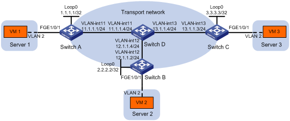
As shown in Figure 9:
· Configure VXLAN 10 as a unicast-mode VXLAN on Switch A, Switch B, and Switch C to provide Layer 2 connectivity for the VMs across the network sites.
· Manually establish VXLAN tunnels and assign the tunnels to VXLAN 10.
· Use the default MAC address learning method (MAC address learning in the data plane).
Configuration procedure
1. Configure IP addresses and unicast routing settings:
# Assign IP addresses to interfaces, as shown in Figure 9. (Details not shown.)
# Configure OSPF on all transport network switches (Switches A through D). (Details not shown.)
2. Configure Switch A:
# Enable L2VPN.
<SwitchA> system-view
[SwitchA] l2vpn enable
# Enable Layer 2 forwarding for all VXLANs.
[SwitchA] undo vxlan ip-forwarding
# Create the VSI vpna and VXLAN 10.
[SwitchA] vsi vpna
[SwitchA-vsi-vpna] vxlan 10
[SwitchA-vsi-vpna-vxlan10] quit
[SwitchA-vsi-vpna] quit
# Assign an IP address to Loopback 0. The IP address will be used as the source IP address of the VXLAN tunnels to Switch B and Switch C.
[SwitchA] interface loopback0
[SwitchA-Loopback0] ip address 1.1.1.1 255.255.255.255
[SwitchA-Loopback0] quit
# Create a VXLAN tunnel to Switch B. The tunnel interface name is Tunnel 1.
[SwitchA] interface tunnel 1 mode vxlan
[SwitchA-Tunnel1] source 1.1.1.1
[SwitchA-Tunnel1] destination 2.2.2.2
[SwitchA-Tunnel1] quit
# Create a VXLAN tunnel to Switch C. The tunnel interface name is Tunnel 2.
[SwitchA] interface tunnel 2 mode vxlan
[SwitchA-Tunnel2] source 1.1.1.1
[SwitchA-Tunnel2] destination 3.3.3.3
[SwitchA-Tunnel2] quit
# Assign Tunnel 1 and Tunnel 2 to VXLAN 10.
[SwitchA] vsi vpna
[SwitchA-vsi-vpna] vxlan 10
[SwitchA-vsi-vpna-vxlan10] tunnel 1
[SwitchA-vsi-vpna-vxlan10] tunnel 2
[SwitchA-vsi-vpna-vxlan10] quit
[SwitchA-vsi-vpna] quit
# Create VLAN 2, and assign FortyGigE 1/0/1 to VLAN 2.
[SwitchA] vlan 2
[SwitchA–vlan2] port fortygige 1/0/1
[SwitchA–vlan2] quit
# On FortyGigE 1/0/1, create Ethernet service instance 1000 to match frames from VLAN 2.
[SwitchA] interface fortygige 1/0/1
[SwitchA-FortyGigE1/0/1] service-instance 1000
[SwitchA-FortyGigE1/0/1-srv1000] encapsulation s-vid 2
# Map Ethernet service instance 1000 to the VSI vpna.
[SwitchA-FortyGigE1/0/1-srv1000] xconnect vsi vpna
[SwitchA-FortyGigE1/0/1-srv1000] quit
[SwitchA-FortyGigE1/0/1] quit
3. Configure Switch B:
# Enable L2VPN.
<SwitchB> system-view
[SwitchB] l2vpn enable
# Enable Layer 2 forwarding for all VXLANs.
[SwitchB] undo vxlan ip-forwarding
# Create the VSI vpna and VXLAN 10.
[SwitchB] vsi vpna
[SwitchB-vsi-vpna] vxlan 10
[SwitchB-vsi-vpna-vxlan10] quit
[SwitchB-vsi-vpna] quit
# Assign an IP address to Loopback 0. The IP address will be used as the source IP address of the VXLAN tunnels to Switch A and Switch C.
[SwitchB] interface loopback0
[SwitchB-Loopback0] ip address 2.2.2.2 255.255.255.255
[SwitchB-Loopback0] quit
# Create a VXLAN tunnel to Switch A. The tunnel interface name is Tunnel 2.
[SwitchB] interface tunnel 2 mode vxlan
[SwitchB-Tunnel2] source 2.2.2.2
[SwitchB-Tunnel2] destination 1.1.1.1
[SwitchB-Tunnel2] quit
# Create a VXLAN tunnel to Switch C. The tunnel interface name is Tunnel 3.
[SwitchB] interface tunnel 3 mode vxlan
[SwitchB-Tunnel3] source 2.2.2.2
[SwitchB-Tunnel3] destination 3.3.3.3
[SwitchB-Tunnel3] quit
# Assign Tunnel 2 and Tunnel 3 to VXLAN 10.
[SwitchB] vsi vpna
[SwitchB-vsi-vpna] vxlan 10
[SwitchB-vsi-vpna-vxlan10] tunnel 2
[SwitchB-vsi-vpna-vxlan10] tunnel 3
[SwitchB-vsi-vpna-vxlan10] quit
[SwitchB-vsi-vpna] quit
# Create VLAN 2, and assign FortyGigE 1/0/1 to VLAN 2.
[SwitchB] vlan 2
[SwitchB–vlan2] port fortygige 1/0/1
[SwitchB–vlan2] quit
# On FortyGigE 1/0/1, create Ethernet service instance 1000 to match frames from VLAN 2.
[SwitchB] interface fortygige 1/0/1
[SwitchB-FortyGigE1/0/1] service-instance 1000
[SwitchB-FortyGigE1/0/1-srv1000] encapsulation s-vid 2
# Map Ethernet service instance 1000 to the VSI vpna.
[SwitchB-FortyGigE1/0/1-srv1000] xconnect vsi vpna
[SwitchB-FortyGigE1/0/1-srv1000] quit
[SwitchB-FortyGigE1/0/1] quit
4. Configure Switch C:
# Enable L2VPN.
<SwitchC> system-view
[SwitchC] l2vpn enable
# Enable Layer 2 forwarding for all VXLANs.
[SwitchC] undo vxlan ip-forwarding
# Create the VSI vpna and VXLAN 10.
[SwitchC] vsi vpna
[SwitchC-vsi-vpna] vxlan 10
[SwitchC-vsi-vpna-vxlan10] quit
[SwitchC-vsi-vpna] quit
# Assign an IP address to Loopback 0. The IP address will be used as the source IP address of the VXLAN tunnels to Switch A and Switch B.
[SwitchC] interface loopback0
[SwitchC-Loopback0] ip address 3.3.3.3 255.255.255.255
[SwitchC-Loopback0] quit
# Create a VXLAN tunnel to Switch A. The tunnel interface name is Tunnel 1.
[SwitchC] interface tunnel 1 mode vxlan
[SwitchC-Tunnel1] source 3.3.3.3
[SwitchC-Tunnel1] destination 1.1.1.1
[SwitchC-Tunnel1] quit
# Create a VXLAN tunnel to Switch B. The tunnel interface name is Tunnel 3.
[SwitchC] interface tunnel 3 mode vxlan
[SwitchC-Tunnel3] source 3.3.3.3
[SwitchC-Tunnel3] destination 2.2.2.2
[SwitchC-Tunnel3] quit
# Assign Tunnel 1 and Tunnel 3 to VXLAN 10.
[SwitchC] vsi vpna
[SwitchC-vsi-vpna] vxlan 10
[SwitchC-vsi-vpna-vxlan10] tunnel 1
[SwitchC-vsi-vpna-vxlan10] tunnel 3
[SwitchC-vsi-vpna-vxlan10] quit
[SwitchC-vsi-vpna] quit
# Create VLAN 2, and assign FortyGigE 1/0/1 to VLAN 2.
[SwitchC] vlan 2
[SwitchC–vlan2] port fortygige 1/0/1
[SwitchC–vlan2] quit
# On FortyGigE 1/0/1, create Ethernet service instance 1000 to match frames from VLAN 2.
[SwitchC] interface fortygige 1/0/1
[SwitchC-FortyGigE1/0/1] service-instance 1000
[SwitchC-FortyGigE1/0/1-srv1000] encapsulation s-vid 2
# Map Ethernet service instance 1000 to the VSI vpna.
[SwitchC-FortyGigE1/0/1-srv1000] xconnect vsi vpna
[SwitchC-FortyGigE1/0/1-srv1000] quit
[SwitchC-FortyGigE1/0/1] quit
Verifying the configuration
1. Verify the VXLAN settings on the VTEPs. This example uses Switch A.
# Verify that the VXLAN tunnel interfaces on the VTEP are up.
[SwitchA] display interface tunnel 1
Tunnel1
Current state: UP
Line protocol state: UP
Description: Tunnel1 Interface
Bandwidth: 64 kbps
Maximum transmission unit: 64000
Internet protocol processing: Disabled
Output queue - Urgent queuing: Size/Length/Discards 0/100/0
Output queue - Protocol queuing: Size/Length/Discards 0/500/0
Output queue - FIFO queuing: Size/Length/Discards 0/75/0
Last clearing of counters: Never
Tunnel source 1.1.1.1, destination 2.2.2.2
Tunnel protocol/transport UDP_VXLAN/IP
# Verify that the VXLAN tunnels have been assigned to the VXLAN.
[SwitchA] display l2vpn vsi verbose
VSI Name: vpna
VSI Index : 0
VSI State : Up
MTU : 1500
Bandwidth : -
Broadcast Restrain : -
Multicast Restrain : -
Unknown Unicast Restrain: -
MAC Learning : Enabled
MAC Table Limit : -
Drop Unknown : -
Flooding : Enabled
VXLAN ID : 10
Tunnels:
Tunnel Name Link ID State Type Flooding proxy
Tunnel1 0x5000001 Up Manual Disabled
Tunnel2 0x5000002 Up Manual Disabled
ACs:
AC Link ID State
FGE1/0/1 srv1000 0 Up
# Verify that the VTEP has learned the MAC addresses of remote VMs.
<SwitchA> display l2vpn mac-address
MAC Address State VSI Name Link ID/Name Aging
cc3e-5f9c-6cdb Dynamic vpna Tunnel1 Aging
cc3e-5f9c-23dc Dynamic vpna Tunnel2 Aging
--- 2 mac address(es) found ---
2. Verify that VM 1, VM 2, and VM 3 can ping each other. (Details not shown.)
Multicast-mode VXLAN configuration example
Network requirements
As shown in Figure 10:
· Configure VXLAN 10 as a multicast-mode VXLAN on Switch A, Switch B, and Switch C to provide Layer 2 connectivity for the VMs across the network sites.
· Manually establish VXLAN tunnels and assign the tunnels to VXLAN 10.
· Use the default remote-MAC address learning method (MAC address learning in the data plane).
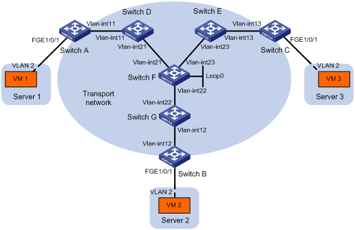
Table 1 IP address assignment
|
Device |
Interface |
IP address |
Device |
Interface |
IP address |
|
Switch A: |
|
|
Switch C: |
|
|
|
|
VLAN-interface 11 |
11.1.1.1/24 |
|
VLAN-interface 13 |
13.1.1.3/24 |
|
Switch D: |
|
|
Switch E: |
|
|
|
|
VLAN-interface 11 |
11.1.1.4/24 |
|
VLAN-interface 13 |
13.1.1.5/24 |
|
|
VLAN-interface 21 |
21.1.1.4/24 |
|
VLAN-interface 23 |
23.1.1.5/24 |
|
Switch F: |
|
|
Switch G: |
|
|
|
|
VLAN-interface 21 |
21.1.1.6/24 |
|
VLAN-interface 12 |
12.1.1.7/24 |
|
|
VLAN-interface 22 |
22.1.1.6/24 |
|
VLAN-interface 22 |
22.1.1.7/24 |
|
|
VLAN-interface 23 |
23.1.1.6/24 |
Switch B: |
|
|
|
|
Loop0 |
6.6.6.6/32 |
|
VLAN-interface 12 |
12.1.1.2/24 |
Configuration procedure
1. Configure IP addresses and unicast routing settings:
# Assign IP addresses to interfaces, as shown in Figure 10. (Details not shown.)
# Configure OSPF on all transport network switches (Switches A through G). (Details not shown.)
2. Configure Switch A:
# Enable L2VPN.
<SwitchA> system-view
[SwitchA] l2vpn enable
# Enable Layer 2 forwarding for VXLANs.
[SwitchA] undo vxlan ip-forwarding
# Enable IP multicast routing.
[SwitchA] multicast routing
[SwitchA-mrib] quit
# Create the VSI vpna and VXLAN 10.
[SwitchA] vsi vpna
[SwitchA-vsi-vpna] vxlan 10
[SwitchA-vsi-vpna-vxlan10] quit
[SwitchA-vsi-vpna] quit
# Assign an IP address to VLAN-interface 11, and enable the IGMP host feature on the interface. This interface's IP address will be the source IP address of VXLAN packets sent by the VTEP.
[SwitchA] interface vlan-interface 11
[SwitchA-Vlan-interface11] ip address 11.1.1.1 24
[SwitchA-Vlan-interface11] igmp host enable
[SwitchA-Vlan-interface11] quit
# Create a VXLAN tunnel to Switch B. The tunnel interface name is Tunnel 1.
[SwitchA] interface tunnel 1 mode vxlan
[SwitchA-Tunnel1] source 11.1.1.1
[SwitchA-Tunnel1] destination 12.1.1.2
[SwitchA-Tunnel1] quit
# Create a VXLAN tunnel to Switch C. The tunnel interface name is Tunnel 2.
[SwitchA] interface tunnel 2 mode vxlan
[SwitchA-Tunnel2] source 11.1.1.1
[SwitchA-Tunnel2] destination 13.1.1.3
[SwitchA-Tunnel2] quit
# Assign Tunnel 1 and Tunnel 2 to VXLAN 10.
[SwitchA] vsi vpna
[SwitchA-vsi-vpna] vxlan 10
[SwitchA-vsi-vpna-vxlan10] tunnel 1
[SwitchA-vsi-vpna-vxlan10] tunnel 2
# Configure the multicast group address and source IP address for multicast VXLAN packets.
[SwitchA-vsi-vpna-vxlan10] group 225.1.1.1 source 11.1.1.1
[SwitchA-vsi-vpna-vxlan10] quit
[SwitchA-vsi-vpna] quit
# Create VLAN 2, and assign FortyGigE 1/0/1 to VLAN 2.
[SwitchA] vlan 2
[SwitchA–vlan2] port fortygige 1/0/1
[SwitchA–vlan2] quit
# On FortyGigE 1/0/1, create Ethernet service instance 1000 to match VLAN 2.
[SwitchA] interface fortygige 1/0/1
[SwitchA-FortyGigE1/0/1] service-instance 1000
[SwitchA-FortyGigE1/0/1-srv1000] encapsulation s-vid 2
# Map Ethernet service instance 1000 to the VSI vpna.
[SwitchA-FortyGigE1/0/1-srv1000] xconnect vsi vpna
[SwitchA-FortyGigE1/0/1-srv1000] quit
[SwitchA-FortyGigE1/0/1] quit
3. Configure Switch B:
# Enable L2VPN.
<SwitchB> system-view
[SwitchB] l2vpn enable
# Enable Layer 2 forwarding for VXLANs.
[SwitchB] undo vxlan ip-forwarding
# Enable IP multicast routing.
[SwitchB] multicast routing
[SwitchB-mrib] quit
# Create the VSI vpna and VXLAN 10.
[SwitchB] vsi vpna
[SwitchB-vsi-vpna] vxlan 10
[SwitchB-vsi-vpna-vxlan10] quit
[SwitchB-vsi-vpna] quit
# Assign an IP address to VLAN-interface 12, and enable the IGMP host feature on the interface. This interface's IP address will be the source IP address of VXLAN packets sent by the VTEP.
[SwitchB] interface vlan-interface 12
[SwitchB-Vlan-interface12] ip address 12.1.1.2 24
[SwitchB-Vlan-interface12] igmp host enable
[SwitchB-Vlan-interface12] quit
# Create a VXLAN tunnel to Switch A. The tunnel interface name is Tunnel 2.
[SwitchB] interface tunnel 2 mode vxlan
[SwitchB-Tunnel2] source 12.1.1.2
[SwitchB-Tunnel2] destination 11.1.1.1
[SwitchB-Tunnel2] quit
# Create a VXLAN tunnel to Switch C. The tunnel interface name is Tunnel 3.
[SwitchB] interface tunnel 3 mode vxlan
[SwitchB-Tunnel3] source 12.1.1.2
[SwitchB-Tunnel3] destination 13.1.1.3
[SwitchB-Tunnel3] quit
# Assign Tunnel 2 and Tunnel 3 to VXLAN 10.
[SwitchB] vsi vpna
[SwitchB-vsi-vpna] vxlan 10
[SwitchB-vsi-vpna-vxlan10] tunnel 2
[SwitchB-vsi-vpna-vxlan10] tunnel 3
# Configure the VXLAN multicast group address and the source IP address for VXLAN packets.
[SwitchB-vsi-vpna-vxlan10] group 225.1.1.1 source 12.1.1.2
[SwitchB-vsi-vpna-vxlan10] quit
[SwitchB-vsi-vpna] quit
# Create VLAN 2, and assign FortyGigE 1/0/1 to VLAN 2.
[SwitchB] vlan 2
[SwitchB–vlan2] port fortygige 1/0/1
[SwitchB–vlan2] quit
# On FortyGigE 1/0/1, create Ethernet service instance 1000 to match VLAN 2.
[SwitchB] interface fortygige 1/0/1
[SwitchB-FortyGigE1/0/1] service-instance 1000
[SwitchB-FortyGigE1/0/1-srv1000] encapsulation s-vid 2
# Map Ethernet service instance 1000 to the VSI vpna.
[SwitchB-FortyGigE1/0/1-srv1000] xconnect vsi vpna
[SwitchB-FortyGigE1/0/1-srv1000] quit
[SwitchB-FortyGigE1/0/1] quit
4. Configure Switch C:
# Enable L2VPN.
<SwitchC> system-view
[SwitchC] l2vpn enable
# Enable Layer 2 forwarding for VXLANs.
[SwitchC] undo vxlan ip-forwarding
# Enable IP multicast routing.
[SwitchC] multicast routing
[SwitchC-mrib] quit
# Create the VSI vpna and VXLAN 10.
[SwitchC] vsi vpna
[SwitchC-vsi-vpna] vxlan 10
[SwitchC-vsi-vpna-vxlan10] quit
[SwitchC-vsi-vpna] quit
# Assign an IP address to VLAN-interface 13, and enable the IGMP host feature on the interface. This interface's IP address will be the source IP address of VXLAN packets sent by the VTEP.
[SwitchC] interface vlan-interface 13
[SwitchC-Vlan-interface13] ip address 13.1.1.3 24
[SwitchC-Vlan-interface13] igmp host enable
[SwitchC-Vlan-interface13] quit
# Create a VXLAN tunnel to Switch A. The tunnel interface name is Tunnel 1.
[SwitchC] interface tunnel 1 mode vxlan
[SwitchC-Tunnel1] source 13.1.1.3
[SwitchC-Tunnel1] destination 11.1.1.1
[SwitchC-Tunnel1] quit
# Create a VXLAN tunnel to Switch B. The tunnel interface name is Tunnel 3.
[SwitchC] interface tunnel 3 mode vxlan
[SwitchC-Tunnel3] source 13.1.1.3
[SwitchC-Tunnel3] destination 12.1.1.2
[SwitchC-Tunnel3] quit
# Assign Tunnel 1 and Tunnel 3 to VXLAN 10.
[SwitchC] vsi vpna
[SwitchC-vsi-vpna] vxlan 10
[SwitchC-vsi-vpna-vxlan10] tunnel 1
[SwitchC-vsi-vpna-vxlan10] tunnel 3
# Configure the multicast group address and source IP address for VXLAN multicast packets.
[SwitchC-vsi-vpna-vxlan10] group 225.1.1.1 source 13.1.1.3
[SwitchC-vsi-vpna-vxlan10] quit
[SwitchC-vsi-vpna] quit
# Create VLAN 2, and assign FortyGigE 1/0/1 to VLAN 2.
[SwitchC] vlan 2
[SwitchC–vlan2] port fortygige 1/0/1
[SwitchC–vlan2] quit
# On FortyGigE 1/0/1, create Ethernet service instance 1000 to match VLAN 2.
[SwitchC] interface fortygige 1/0/1
[SwitchC-FortyGigE1/0/1] service-instance 1000
[SwitchC-FortyGigE1/0/1-srv1000] encapsulation s-vid 2
# Map Ethernet service instance 1000 to the VSI vpna.
[SwitchC-FortyGigE1/0/1-srv1000] xconnect vsi vpna
[SwitchC-FortyGigE1/0/1-srv1000] quit
[SwitchC-FortyGigE1/0/1] quit
5. Configure Switch D:
# Enable IP multicast routing.
<SwitchD> system-view
[SwitchD] multicast routing
[SwitchD-mrib] quit
# Enable IGMP and PIM-SM on VLAN-interface 11.
[SwitchD] interface vlan-interface 11
[SwitchD-Vlan-interface11] igmp enable
[SwitchD-Vlan-interface11] pim sm
[SwitchD-Vlan-interface11] quit
# Enable PIM-SM on VLAN-interface 21.
[SwitchD] interface vlan-interface 21
[SwitchD-Vlan-interface21] pim sm
[SwitchD-Vlan-interface21] quit
6. Configure Switch E:
# Enable IP multicast routing.
<SwitchE> system-view
[SwitchE] multicast routing
[SwitchE-mrib] quit
# Enable IGMP and PIM-SM on VLAN-interface 13.
[SwitchE] interface vlan-interface 13
[SwitchE-Vlan-interface13] igmp enable
[SwitchE-Vlan-interface13] pim sm
[SwitchE-Vlan-interface13] quit
# Enable PIM-SM on VLAN-interface 23.
[SwitchE] interface vlan-interface 23
[SwitchE-Vlan-interface23] pim sm
[SwitchE-Vlan-interface23] quit
7. Configure Switch F:
# Enable IP multicast routing.
<SwitchF> system-view
[SwitchF] multicast routing
[SwitchF-mrib] quit
# Enable PIM-SM on VLAN-interface 21, VLAN-interface 22, and VLAN-interface 23.
[SwitchF] interface vlan-interface 21
[SwitchF-Vlan-interface21] pim sm
[SwitchF-Vlan-interface21] quit
[SwitchF] interface vlan-interface 22
[SwitchF-Vlan-interface22] pim sm
[SwitchF-Vlan-interface22] quit
[SwitchF] interface vlan-interface 23
[SwitchF-Vlan-interface23] pim sm
[SwitchF-Vlan-interface23] quit
8. Configure Switch G:
# Enable IP multicast routing.
<SwitchG> system-view
[SwitchG] multicast routing
[SwitchG-mrib] quit
# Enable IGMP and PIM-SM on VLAN-interface 12.
[SwitchG] interface vlan-interface 12
[SwitchG-Vlan-interface12] igmp enable
[SwitchG-Vlan-interface12] pim sm
[SwitchG-Vlan-interface12] quit
# Enable PIM-SM on VLAN-interface 22.
[SwitchG] interface vlan-interface 22
[SwitchG-Vlan-interface22] pim sm
[SwitchG-Vlan-interface22] quit
Verifying the configuration
1. Verify the VXLAN settings on the VTEPs. This example uses Switch A.
# Verify that the VXLAN tunnel interfaces on the VTEP are up.
[SwitchA] display interface tunnel 1
Tunnel1
Current state: UP
Line protocol state: UP
Description: Tunnel1 Interface
Bandwidth: 64 kbps
Maximum transmission unit: 64000
Internet protocol processing: Disabled
Last clearing of counters: Never
Tunnel source 11.1.1.1, destination 12.1.1.2
Tunnel protocol/transport UDP_VXLAN/IP
# Verify that the VXLAN tunnels have been assigned to the VXLAN.
[SwitchA] display l2vpn vsi verbose
VSI Name: vpna
VSI Index : 0
VSI State : Up
MTU : 1500
Bandwidth : -
Broadcast Restrain : -
Multicast Restrain : -
Unknown Unicast Restrain: -
MAC Learning : Enabled
MAC Table Limit : -
Drop Unknown : Disabled
Flooding : Enabled
VXLAN ID : 10
Tunnels:
Tunnel Name Link ID State Type Flooding proxy
Tunnel1 0x5000001 Up Manual Disabled
Tunnel2 0x5000002 Up Manual Disabled
MTunnel0 0x6000000 Up Auto Disabled
ACs:
AC Link ID State
FGE1/0/1 srv1000 0 Up
# Verify that the VTEP has learned the MAC addresses of remote VMs.
<SwitchA> display l2vpn mac-address
MAC Address State VSI Name Link ID/Name Aging
cc3e-5f9c-6cdb Dynamic vpna Tunnel1 Aging
cc3e-5f9c-23dc Dynamic vpna Tunnel2 Aging
--- 2 mac address(es) found ---
# Verify that the VTEP has joined the VXLAN multicast group on VLAN-interface 11.
<SwitchA> display igmp host group
IGMP host groups in total: 1
Vlan-interface11(11.1.1.1):
IGMP host groups in total: 1
Group address Member state Expires
225.1.1.1 Idle Off
2. Verify that VM 1, VM 2, and VM 3 can ping each other. (Details not shown.)
Configuring VXLAN IP gateways
Overview
The following are available IP gateway placement designs for VXLANs:
· VXLAN IP gateways separated from VTEPs—Use a VXLAN-unaware device as a gateway to the external network for VXLANs. On the gateway, you do not need to configure VXLAN settings.
· VXLAN IP gateways collocated with VTEPs—Use one VTEP or multiple VTEPs to provide Layer 3 forwarding for VXLANs. Typically, the gateway-collocated VTEP connects to other VTEPs and the external network. To use this design, make sure the IP gateway has sufficient bandwidth and processing capability.
In a collocation design, the VTEPs use virtual Layer 3 VSI interfaces as gateway interfaces to provide services for VXLANs.
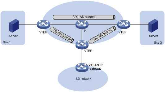
VXLAN IP gateways separated from VTEPs
As shown in Figure 11, an independent VXLAN IP gateway connects a Layer 3 network to a VTEP. VMs send Layer 3 traffic to the gateway through VXLAN tunnels. When the Layer 3 traffic arrives, the VTEP terminates the VXLANs and forwards the inner frames to the gateway. In this gateway placement design, the VTEP does not perform Layer 3 forwarding for VXLANs.
Figure 11 VXLAN IP gateway separated from VTEPs
Centralized VXLAN IP gateway deployment
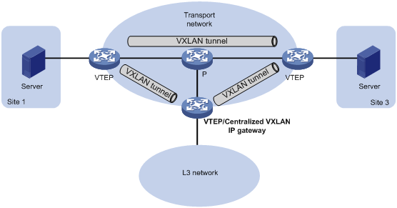
As shown in Figure 12, a VTEP acts as a gateway for VMs in the VXLANs. The VTEP both terminates the VXLANs and performs Layer 3 forwarding for the VMs. In this solution, the VTEP provides gateway services for VXLANs on virtual Layer 3 VSI interfaces.
Figure 12 Centralized VXLAN IP gateway deployment
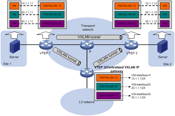
As shown in Figure 13, the network uses the following process to forward Layer 3 traffic from VM 10.1.1.11 to the Layer 3 network:
1. The VM sends an ARP request to obtain the MAC address of the gateway (VTEP 3) at 10.1.1.1.
2. VTEP 1 floods the ARP request to all remote VTEPs.
3. VTEP 3 de-encapsulates the ARP request, creates an ARP entry for the VM, and sends an ARP reply to the VM.
4. VTEP 1 forwards the ARP reply to the VM.
5. The VM learns the MAC address of the gateway, and sends the Layer 3 traffic to the gateway.
6. VTEP 3 removes the VXLAN encapsulation and inner Ethernet header for the traffic, and forwards the traffic to the destination node.
Inter-VXLAN forwarding is the same as this process except for the last step. At the last step of inter-VLAN forwarding, the gateway replaces the source-VXLAN encapsulation with the destination-VXLAN encapsulation, and then forwards the traffic.
Figure 13 Example of centralized VXLAN IP gateway deployment
Centralized VXLAN IP gateway group deployment
As shown in Figure 14, a VTEP group uses redundant centralized VXLAN IP gateways to provide reliable gateway services for VMs in the VXLANs. All member VTEPs in the group participate in Layer 3 forwarding and load share traffic between the Layer 3 network and the VXLANs. This design distributes processing among multiple VTEPs and prevents single points of failure.
Figure 14 Example of centralized VXLAN IP gateway group deployment
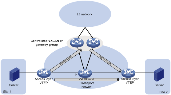
The VTEP group is a virtual gateway that provides services at a group IP address. Access layer VTEPs set up VXLAN tunnels to the group IP address for data traffic forwarding. Each VTEP in the group automatically uses its member IP address to set up tunnels to the other member VTEPs and access layer VTEPs. The tunnels are used to transmit protocol packets and synchronize ARP entries.
Configuration restrictions and guidelines
Reserve one global-type VLAN interface resource for the VSI interface of each VXLAN before the VXLAN is created if you enable Layer 3 forwarding for VXLANs. For more information about reserving global-type VLAN interface resources, see VLAN configuration in Layer 2—LAN Switching Configuration Guide.
As a best practice, deploy Layer 2 Ethernet interfaces of the access link type or Layer 3 Ethernet interfaces as the outgoing interfaces of VXLAN packets on a VXLAN IP gateway. To use Layer 2 Ethernet interfaces of the trunk link type or Layer 3 Ethernet subinterfaces, you must execute the vxlan ip-forwarding tagged command. The gateway can provide a maximum of 16 VLAN tags for VXLAN packets.
Configuration prerequisites
Before you configure a centralized VXLAN IP gateway, you must perform the following tasks on VTEPs:
· Enable Layer 3 forwarding for VXLANs.
· Create VSIs and VXLANs.
· Configure VXLAN tunnels and assign them to VXLANs.
Configuring a centralized VXLAN IP gateway on a VTEP
|
Step |
Command |
Remarks |
|
|
1. Enter system view. |
system-view |
N/A |
|
|
2. Create a VSI interface and enter VSI interface view. |
interface vsi-interface vsi-interface-id |
By default, no VSI interfaces are created on the device. |
|
|
3. Assign an IPv4 address to the VSI interface. |
ip address ip-address { mask | mask-length } |
By default, no IPv4 address is assigned to a VSI interface. |
|
|
4. Return to system view. |
quit |
N/A |
|
|
5. Enter VSI view. |
vsi vsi-name |
N/A |
|
|
6. Specify the VSI interface as the gateway interface for the VSI. |
gateway vsi-interface vsi-interface-id |
By default, no gateway interface is specified for a VSI. |
|
Configuring a centralized VXLAN IP gateway group
Configuring a VTEP group
Make sure the member VTEPs use the same VXLAN settings.
To configure a VTEP group on a member VTEP:
|
Step |
Command |
Remarks |
|
1. Enter system view. |
system-view |
N/A |
|
2. Create a VSI interface and enter VSI interface view. |
interface vsi-interface vsi-interface-id |
By default, no VSI interfaces exist. You must create the same VSI interface on all VTEPs in the VTEP group. |
|
3. Assign an IP address to the VSI interface. |
ip address ip-address { mask | mask-length } [ sub ] |
By default, no IP address is assigned to a VSI interface. You must assign the same IP address to the VSI interface on each VTEP in the VTEP group. |
|
4. Assign a MAC address to the VSI interface. |
mac-address mac-address |
By default, the MAC address of VLAN interfaces applies. You must assign the same MAC address to the VSI interface on each VTEP in the VTEP group. |
|
5. Return to system view. |
quit |
N/A |
|
6. Enter VSI view. |
vsi vsi-name |
N/A |
|
7. Specify a gateway interface for the VSI. |
gateway vsi-interface vsi-interface-id |
By default, no gateway interface is specified for a VSI. |
|
8. Return to system view. |
quit |
N/A |
|
9. Assign the local VTEP to a VTEP group and specify the member IP address for the VTEP. |
vtep group group-ip member local member-ip |
By default, a VTEP is not assigned to any VTEP group. Perform this task on all member VTEPs in the VTEP group. The IP address specified by the member-ip argument must already exist on the local VTEP. You must configure a routing protocol to advertise the IP address in the transport network. Member VTEPs in a VTEP group cannot use the group IP address or share an IP address. |
|
10. Specify all the other VTEPs in the VTEP group. |
vtep group group-ip member remote member-ip&<1-8> |
By default, no VTEP group is specified. Perform this task on all member VTEPs in the VTEP group. |
Specifying a VTEP group as the gateway for an access layer VTEP
Before you specify a VTEP group on an access layer VTEP, perform the following tasks on the VTEP:
· Enable Layer 2 forwarding for VXLANs.
· Configure VSIs and VXLANs.
· Set up VXLAN tunnels to remote sites and the VTEP group, and assign the tunnels to VXLANs.
To specify a VTEP group as the gateway for an access layer VTEP:
|
Step |
Command |
Remarks |
|
1. Enter system view. |
system-view |
N/A |
|
2. Specify a VTEP group and all its member VTEPs. |
vtep group group-ip member remote member-ip&<1-8> |
By default, no VTEP group is specified. |
Configuring a VSI interface
|
Step |
Command |
Remarks |
|
|
1. Enter system view. |
system-view |
N/A |
|
|
2. Enter VSI interface view. |
interface vsi-interface vsi-interface-id |
N/A |
|
|
3. (Optional.) Assign a MAC address to the VSI interface. |
mac-address mac-address |
By default, the MAC address of a VSI interface is the same as the MAC address of VLAN interfaces. If the specified MAC address has the same higher 36 bits as the device's bridge MAC address, the specified MAC address is used as the source MAC address of the packets sent by the VSI interface. If the specified MAC address does not meet this requirement, the default MAC address is used as the source MAC address of the packets sent by the VSI interface. The device supports a maximum of eight VSI interface MAC addresses if the higher 36 bits of the MAC addresses are different than the device's bridge MAC address. As a best practice, assign VSI interfaces the MAC addresses that have the same higher 36 bits as the device's bridge MAC address if more than eight MAC addresses are required. |
|
|
4. Set an ARP packet sending rate limit for the VSI interface. |
arp send-rate pps |
By default, the ARP packet sending rate is not limited for a VSI interface. |
|
|
5. (Optional.) Configure a description for the VSI interface. |
description text |
The default description of a VSI interface is interface-name plus Interface (for example, Vsi-interface100 Interface). |
|
|
6. (Optional.) Set the MTU for the VSI interface. |
mtu mtu-value |
The default MTU is 1500 bytes. |
|
|
7. (Optional.) Set the expected bandwidth for the VSI interface. |
bandwidth bandwidth-value |
The default expected bandwidth is 1000000 kbps. |
|
|
8. (Optional.) Restore the default settings on the interface |
default |
N/A |
|
|
9. (Optional.) Bring up the interface. |
undo shutdown |
By default, a VSI interface is up. |
|
Enabling packet statistics for VSI interfaces
The statistic mode vsi command takes effect only if the VSI interface is associated with only one VSI.
If you execute the statistic mode command multiple times, the most recent configuration takes effect.
To enable packet statistics for VSI interfaces:
|
Step |
Command |
Remarks |
|
1. Enter system view. |
system-view |
N/A |
|
2. Set the packet statistic collection mode to VSI. |
statistic mode vsi |
By default, the packet statistic collection mode is VSI. |
|
3. Enter VSI view. |
vsi vsi-name |
N/A |
|
4. Enable the packet statistics feature for the VSI. |
statistics enable |
By default, the packet statistics feature is disabled for all VSIs. |
Displaying and maintaining VXLAN IP gateway
Execute display commands in any view and reset commands in user view.
|
Task |
Command |
|
Display information about VSI interfaces. |
display interface [ vsi-interface [ vsi-interface-id ] ] [ brief [ description ] ] |
|
Clear statistics on VSI interfaces. |
reset counters interface [ vsi-interface [ vsi-interface-id ] ] |
VXLAN IP gateway configuration examples
Centralized VXLAN IP gateway configuration example
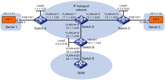
Network requirements
As shown in Figure 15:
· Configure VXLAN 10 on Switch A through Switch C to provide connectivity for the VMs across the network sites.
· Manually establish VXLAN tunnels and assign the tunnels to VXLAN 10.
· Configure a centralized VXLAN IP gateway on Switch B for VXLAN 10 to access the WAN.
Configuration procedure
1. Configure IP addresses and unicast routing settings:
# Assign IP addresses to interfaces, as shown in Figure 15. (Details not shown.)
# Configure OSPF on all transport network switches (Switches A through D). (Details not shown.)
# Configure OSPF to advertise routes to networks 10.1.1.0/24 and 20.1.1.0/24 on Switch B and Switch E. (Details not shown.)
2. Configure Switch A:
# Enable L2VPN.
<SwitchA> system-view
[SwitchA] l2vpn enable
# Enable Layer 2 forwarding for VXLANs.
[SwitchA] undo vxlan ip-forwarding
# Create the VSI vpna and VXLAN 10.
[SwitchA] vsi vpna
[SwitchA-vsi-vpna] vxlan 10
[SwitchA-vsi-vpna-vxlan10] quit
[SwitchA-vsi-vpna] quit
# Assign an IP address to Loopback 0. The IP address will be used as the source IP address of the VXLAN tunnels to Switch B and Switch C.
[SwitchA] interface loopback0
[SwitchA-Loopback0] ip address 1.1.1.1 255.255.255.255
[SwitchA-Loopback0] quit
# Create a VXLAN tunnel to Switch B. The tunnel interface name is Tunnel 1.
[SwitchA] interface tunnel 1 mode vxlan
[SwitchA-Tunnel1] source 1.1.1.1
[SwitchA-Tunnel1] destination 2.2.2.2
[SwitchA-Tunnel1] quit
# Create a VXLAN tunnel to Switch C. The tunnel interface name is Tunnel 2.
[SwitchA] interface tunnel 2 mode vxlan
[SwitchA-Tunnel2] source 1.1.1.1
[SwitchA-Tunnel2] destination 3.3.3.3
[SwitchA-Tunnel2] quit
# Assign Tunnel 1 and Tunnel 2 to VXLAN 10.
[SwitchA] vsi vpna
[SwitchA-vsi-vpna] vxlan 10
[SwitchA-vsi-vpna-vxlan10] tunnel 1
[SwitchA-vsi-vpna-vxlan10] tunnel 2
[SwitchA-vsi-vpna-vxlan10] quit
[SwitchA-vsi-vpna] quit
# Create VLAN 2, and assign FortyGigE 1/0/1 to VLAN 2.
[SwitchA] vlan 2
[SwitchA–vlan2] port fortygige 1/0/1
[SwitchA–vlan2] quit
# On FortyGigE 1/0/1, create Ethernet service instance 1000 to match frames from VLAN 2.
[SwitchA] interface fortygige 1/0/1
[SwitchA-FortyGigE1/0/1] service-instance 1000
[SwitchA-FortyGigE1/0/1-srv1000] encapsulation s-vid 2
# Map Ethernet service instance 1000 to the VSI vpna.
[SwitchA-FortyGigE1/0/1-srv1000] xconnect vsi vpna
[SwitchA-FortyGigE1/0/1-srv1000] quit
[SwitchA-FortyGigE1/0/1] quit
3. Configure Switch B:
# Enable L2VPN.
<SwitchB> system-view
[SwitchB] l2vpn enable
# Reserve a global-type VLAN interface resource. In this example, VLAN-interface 3000 is reserved.
[SwitchB] reserve-vlan-interface 3000 global
# Create the VSI vpna and VXLAN 10.
[SwitchB] vsi vpna
[SwitchB-vsi-vpna] vxlan 10
[SwitchB-vsi-vpna-vxlan10] quit
[SwitchB-vsi-vpna] quit
# Assign an IP address to Loopback 0. The IP address will be used as the source IP address of the VXLAN tunnels to Switch A and Switch C.
[SwitchB] interface loopback0
[SwitchB-Loopback0] ip address 2.2.2.2 255.255.255.255
[SwitchB-Loopback0] quit
# Create a VXLAN tunnel to Switch A. The tunnel interface name is Tunnel 2.
[SwitchB] interface tunnel 2 mode vxlan
[SwitchB-Tunnel2] source 2.2.2.2
[SwitchB-Tunnel2] destination 1.1.1.1
[SwitchB-Tunnel2] quit
# Create a VXLAN tunnel to Switch C. The tunnel interface name is Tunnel 3.
[SwitchB] interface tunnel 3 mode vxlan
[SwitchB-Tunnel3] source 2.2.2.2
[SwitchB-Tunnel3] destination 3.3.3.3
[SwitchB-Tunnel3] quit
# Assign Tunnel 2 and Tunnel 3 to VXLAN 10.
[SwitchB] vsi vpna
[SwitchB-vsi-vpna] vxlan 10
[SwitchB-vsi-vpna-vxlan10] tunnel 2
[SwitchB-vsi-vpna-vxlan10] tunnel 3
[SwitchB-vsi-vpna-vxlan10] quit
[SwitchB-vsi-vpna] quit
# Create VSI-interface 1 and assign the interface an IP address. The IP address will be used as the gateway address for VXLAN 10.
[SwitchB] interface vsi-interface 1
[SwitchB-Vsi-interface1] ip address 10.1.1.1 255.255.255.0
[SwitchB-Vsi-interface1] quit
# Specify VSI-interface 1 as the gateway interface for the VSI vpna.
[SwitchB] vsi vpna
[SwitchB-vsi-vpna] gateway vsi-interface 1
[SwitchB-vsi-vpna] quit
4. Configure Switch C:
# Enable L2VPN.
<SwitchC> system-view
[SwitchC] l2vpn enable
# Enable Layer 2 forwarding for VXLANs.
[SwitchC] undo vxlan ip-forwarding
# Create the VSI vpna and VXLAN 10.
[SwitchC] vsi vpna
[SwitchC-vsi-vpna] vxlan 10
[SwitchC-vsi-vpna-vxlan10] quit
[SwitchC-vsi-vpna] quit
# Assign an IP address to Loopback 0. The IP address will be used as the source IP address of the VXLAN tunnels to Switch A and Switch B.
[SwitchC] interface loopback0
[SwitchC-Loopback0] ip address 3.3.3.3 255.255.255.255
[SwitchC-Loopback0] quit
# Create a VXLAN tunnel to Switch A. The tunnel interface name is Tunnel 1.
[SwitchC] interface tunnel 1 mode vxlan
[SwitchC-Tunnel1] source 3.3.3.3
[SwitchC-Tunnel1] destination 1.1.1.1
[SwitchC-Tunnel1] quit
# Create a VXLAN tunnel to Switch B. The tunnel interface name is Tunnel 3.
[SwitchC] interface tunnel 3 mode vxlan
[SwitchC-Tunnel3] source 3.3.3.3
[SwitchC-Tunnel3] destination 2.2.2.2
[SwitchC-Tunnel3] quit
# Assign Tunnel 1 and Tunnel 3 to VXLAN 10.
[SwitchC] vsi vpna
[SwitchC-vsi-vpna] vxlan 10
[SwitchC-vsi-vpna-vxlan10] tunnel 1
[SwitchC-vsi-vpna-vxlan10] tunnel 3
[SwitchC-vsi-vpna-vxlan10] quit
[SwitchC-vsi-vpna] quit
# Create VLAN 2, and assign FortyGigE 1/0/1 to VLAN 2.
[SwitchC] vlan 2
[SwitchC–vlan2] port fortygige 1/0/1
[SwitchC–vlan2] quit
# On FortyGigE 1/0/1, create Ethernet service instance 1000 to match frames from VLAN 2.
[SwitchC] interface fortygige 1/0/1
[SwitchC-FortyGigE1/0/1] service-instance 1000
[SwitchC-FortyGigE1/0/1-srv1000] encapsulation s-vid 2
# Map Ethernet service instance 1000 to the VSI vpna.
[SwitchC-FortyGigE1/0/1-srv1000] xconnect vsi vpna
[SwitchC-FortyGigE1/0/1-srv1000] quit
[SwitchC-FortyGigE1/0/1] quit
Verifying the configuration
1. Verify the VXLAN IP gateway settings on Switch B:
# Verify that the VXLAN tunnel interfaces are up on Switch B.
[SwitchB] display interface tunnel 2
Tunnel2
Current state: UP
Line protocol state: UP
Description: Tunnel1 Interface
Bandwidth: 64 kbps
Maximum transmission unit: 64000
Internet protocol processing: Disabled
Last clearing of counters: Never
Tunnel source 2.2.2.2, destination 1.1.1.1
Tunnel protocol/transport UDP_VXLAN/IP
# Verify that VSI-interface 1 is up.
[SwitchB] display interface vsi-interface 1
Vsi-interface1
Current state: UP
Line protocol state: UP
Description: Vsi-interface100 Interface
Bandwidth: 1000000kbps
Maximum transmission unit: 1500
Internet Address is 10.1.1.1/24 Primary
IP Packet Frame Type:PKTFMT_ETHNT_2, Hardware Address: 0011-2200-0102
IPv6 Packet Frame Type:PKTFMT_ETHNT_2, Hardware Address: 0011-2200-0102
Physical: Unknown, baudrate: 1000000 kbps
Last clearing of counters: Never
Last 300 seconds input rate: 0 bytes/sec, 0 bits/sec, 0 packets/sec
Last 300 seconds output rate: 0 bytes/sec, 0 bits/sec, 0 packets/sec
Input: 0 packets, 0 bytes, 0 drops
Output: 0 packets, 0 bytes, 0 drops
# Verify that the VXLAN tunnels have been assigned to the VXLAN, and VSI-interface 1 is the gateway interface of the VSI vpna.
[SwitchB] display l2vpn vsi verbose
VSI Name: vpna
VSI Index : 0
VSI State : Up
MTU : 1500
Bandwidth : -
Broadcast Restrain : -
Multicast Restrain : -
Unknown Unicast Restrain: -
MAC Learning : Enabled
MAC Table Limit : -
Drop Unknown : -
Flooding : Enabled
Gateway interface : VSI-interface 1
VXLAN ID : 10
Tunnels:
Tunnel Name Link ID State Type Flooding proxy
Tunnel2 0x5000002 Up Manual Disabled
Tunnel3 0x5000003 Up Manual Disabled
# Verify that Switch B has created ARP entries for the VMs.
[SwitchB] display arp
Type: S-Static D-Dynamic O-Openflow R-Rule M-Multiport I-Invalid
IP Address MAC Address VID Interface/Link ID Aging Type
20.1.1.5 000c-29c1-5e46 N/A Vlan20 19 D
10.1.1.11 0000-1234-0001 N/A Vsi10 20 D
10.1.1.12 0000-1234-0002 N/A Vsi10 19 D
# Verify that Switch B has created FIB entries for the VMs.
[SwitchB] display fib 10.1.1.11
Destination count: 1 FIB entry count: 1
Flag:
U:Useable G:Gateway H:Host B:Blackhole D:Dynamic S:Static
R:Relay F:FRR
Destination/Mask Nexthop Flag OutInterface/Token Label
10.1.1.11/32 10.1.1.11 UH Vsi10 Null
2. Verify that the VMs can access the WAN:
# Verify that VM 1 and VM 2 can ping each other. (Details not shown.)
# Verify that VM 1, VM 2, and VLAN-interface 20 (20.1.1.5) on Switch E can ping each other. (Details not shown.)
Centralized VXLAN IP gateway group configuration example
Network requirements
As shown in Figure 16:
· Configure VXLAN 10 as a unicast-mode VXLAN on Switch A, Switch B, and Switch C.
· Manually establish VXLAN tunnels and assign the tunnels to VXLAN 10.
· Assign Switch B and Switch C to a VTEP group to provide gateway services for VXLAN 10.
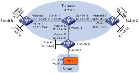
Configuration procedure
1. On VM 1, specify 10.1.1.1 as the gateway address. (Details not shown.)
2. Configure IP addresses and unicast routing settings:
# Assign IP addresses to interfaces, as shown in Figure 16. (Details not shown.)
# Configure OSPF on all transport network switches (Switches A through D). (Details not shown.)
3. Configure Switch A:
# Enable L2VPN.
<SwitchA> system-view
[SwitchA] l2vpn enable
# Enable Layer 2 forwarding for VXLANs.
[SwitchA] undo vxlan ip-forwarding
# Create the VSI vpna and VXLAN 10.
[SwitchA] vsi vpna
[SwitchA-vsi-vpna] vxlan 10
[SwitchA-vsi-vpna-vxlan-10] quit
[SwitchA-vsi-vpna] quit
# Assign an IP address to Loopback 0. The IP address will be used as the source IP address of the VXLAN tunnel to the VTEP group.
[SwitchA] interface loopback 0
[SwitchA-Loopback0] ip address 1.1.1.1 255.255.255.255
[SwitchA-Loopback0] quit
# Create a VXLAN tunnel to the VTEP group. The tunnel interface name is Tunnel 1.
[SwitchA] interface tunnel 1 mode vxlan
[SwitchA-Tunnel1] source 1.1.1.1
[SwitchA-Tunnel1] destination 2.2.2.2
[SwitchA-Tunnel1] quit
# Assign Tunnel 1 to VXLAN 10.
[SwitchA] vsi vpna
[SwitchA-vsi-vpna] vxlan 10
[SwitchA-vsi-vpna-vxlan-10] tunnel 1
[SwitchA-vsi-vpna-vxlan-10] quit
[SwitchA-vsi-vpna] quit
# Create VLAN 2 and assign FortyGigE 1/0/1 to VLAN 2.
[SwitchA] vlan 2
[SwitchA–vlan2] port fortygige 1/0/1
[SwitchA–vlan2] quit
# On FortyGigE 1/0/1, create Ethernet service instance 1000 to match VLAN 2.
[SwitchA] interface fortygige 1/0/1
[SwitchA-FortyGigE1/0/1] service-instance 1000
[SwitchA-FortyGigE1/0/1-srv1000] encapsulation s-vid 2
# Map Ethernet service instance 1000 to the VSI vpna.
[SwitchA-FortyGigE1/0/1-srv1000] xconnect vsi vpna
[SwitchA-FortyGigE1/0/1-srv1000] quit
[SwitchA-FortyGigE1/0/1] quit
# Specify the VTEP group 2.2.2.2 and its member VTEPs at 3.3.3.3 and 4.4.4.4.
[SwitchA] vtep group 2.2.2.2 member remote 3.3.3.3 4.4.4.4
4. Configure Switch B:
# Enable L2VPN.
<SwitchB> system-view
[SwitchB] l2vpn enable
# Reserve the global resource of VLAN-interface 3000.
[SwitchB] reserve-vlan-interface 3000 global
# Create the VSI vpna and VXLAN 10.
[SwitchB] vsi vpna
[SwitchB-vsi-vpna] vxlan 10
[SwitchB-vsi-vpna-vxlan-10] quit
[SwitchB-vsi-vpna] quit
# Assign IP address 2.2.2.2/32 to Loopback 0. The IP address will be used as the IP address of the VTEP group.
[SwitchB] interface loopback 0
[SwitchB-Loopback0] ip address 2.2.2.2 255.255.255.255
[SwitchB-Loopback0] quit
# Assign an IP address to Loopback 1. The IP address will be used as the member IP address of the VTEP.
[SwitchB] interface loopback 1
[SwitchB-Loopback1] ip address 3.3.3.3 255.255.255.255
[SwitchB-Loopback1] quit
# Create a VXLAN tunnel to Switch A. The tunnel source IP address is 2.2.2.2, and the tunnel interface name is Tunnel 2.
[SwitchB] interface tunnel 2 mode vxlan
[SwitchB-Tunnel2] source 2.2.2.2
[SwitchB-Tunnel2] destination 1.1.1.1
[SwitchB-Tunnel2] quit
# Assign Tunnel 2 to VXLAN 10.
[SwitchB] vsi vpna
[SwitchB-vsi-vpna] vxlan 10
[SwitchB-vsi-vpna-vxlan-10] tunnel 2
[SwitchB-vsi-vpna-vxlan-10] quit
[SwitchB-vsi-vpna] quit
# Create VSI-interface 1 and assign the interface an IP address. The IP address will be used as the gateway address for VXLAN 10. Assign a MAC address to the interface.
[SwitchB] interface vsi-interface 1
[SwitchB-Vsi-interface1] ip address 10.1.1.1 255.255.255.0
[SwitchB-Vsi-interface1] mac-address 2-2-2
[SwitchB-Vsi-interface1] quit
# Specify VSI-interface 1 as the gateway interface for the VSI vpna.
[SwitchB] vsi vpna
[SwitchB-vsi-vpna] gateway vsi-interface 1
[SwitchB-vsi-vpna] quit
# Assign the local VTEP to the VTEP group 2.2.2.2, and specify the member IP address of the local VTEP.
[SwitchB] vtep group 2.2.2.2 member local 3.3.3.3
# Specify the other member VTEP Switch C.
[SwitchB] vtep group 2.2.2.2 member remote 4.4.4.4
5. Configure Switch C:
# Enable L2VPN.
<SwitchC> system-view
[SwitchC] l2vpn enable
# Reserve the global resource of VLAN-interface 3000.
[SwitchC] reserve-vlan-interface 3000 global
# Create the VSI vpna and VXLAN 10.
[SwitchC] vsi vpna
[SwitchC-vsi-vpna] vxlan 10
[SwitchC-vsi-vpna-vxlan-10] quit
[SwitchC-vsi-vpna] quit
# Assign IP address 2.2.2.2/32 to Loopback 0. The IP address will be used as the IP address of the VTEP group.
[SwitchC] interface loopback 0
[SwitchC-Loopback0] ip address 2.2.2.2 255.255.255.255
[SwitchC-Loopback0] quit
# Assign an IP address to Loopback 1. The IP address will be used as the member IP address of the VTEP.
[SwitchC] interface loopback 1
[SwitchC-Loopback1] ip address 4.4.4.4 255.255.255.255
[SwitchC-Loopback1] quit
# Create a VXLAN tunnel to Switch A. The tunnel source IP address is 2.2.2.2, and the tunnel interface name is Tunnel 2.
[SwitchC] interface tunnel 2 mode vxlan
[SwitchC-Tunnel2] source 2.2.2.2
[SwitchC-Tunnel2] destination 1.1.1.1
[SwitchC-Tunnel2] quit
# Assign Tunnel 2 to VXLAN 10.
[SwitchC] vsi vpna
[SwitchC-vsi-vpna] vxlan 10
[SwitchC-vsi-vpna-vxlan-10] tunnel 2
[SwitchC-vsi-vpna-vxlan-10] quit
[SwitchC-vsi-vpna] quit
# Create VSI-interface 1 and assign the interface an IP address. The IP address will be used as the gateway address for VXLAN 10. Assign a MAC address to the interface.
[SwitchC] interface vsi-interface 1
[SwitchC-Vsi-interface1] ip address 10.1.1.1 255.255.255.0
[SwitchC-Vsi-interface1] mac-address 2-2-2
[SwitchC-Vsi-interface1] quit
# Specify VSI-interface 1 as the gateway interface for the VSI vpna.
[SwitchC] vsi vpna
[SwitchC-vsi-vpna] gateway vsi-interface 1
[SwitchC-vsi-vpna] quit
# Assign the local VTEP to the VTEP group 2.2.2.2, and specify the member IP address of the local VTEP.
[SwitchC] vtep group 2.2.2.2 member local 4.4.4.4
# Specify the other member VTEP Switch B.
[SwitchC] vtep group 2.2.2.2 member remote 3.3.3.3
Configuring the VTEP as an OVSDB VTEP
Overview
An H3C network virtualization controller can use the Open vSwitch Database (OVSDB) management protocol to deploy and manage VXLANs on VTEPs. To work with a controller, you must configure the VTEP as an OVSDB VTEP.
As shown in Figure 17, an OVSDB VTEP stores all of its VXLAN settings in the form of entries in an OVSDB database. The OVSDB database, OVSDB VTEP service, and the controller interact through the OVSDB server. The controller communicates with the OVSDB server through the OVSDB protocol to manage the OVSDB database. The OVSDB VTEP service reads and writes data in the OVSDB database through the OVSDB server.
The OVSDB VTEP service performs the following operations to manage the VXLAN settings on the VTEP:
· Converts data in the OVSDB database into VXLAN configuration and deploys the configuration to the VTEP. For example, create or remove a VXLAN or VXLAN tunnel.
· Adds site-facing interface information and the global source address of VXLAN tunnels to the OVSDB database. The information is reported to the controller by the OVSDB server.
You can configure a VTEP both at the CLI and through a controller. As a best practice, do not manually remove the VXLAN configuration issued by the controller.
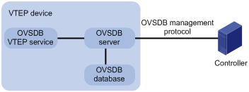
Protocols and standards
RFC 7047, The Open vSwitch Database Management Protocol
OVSDB VTEP configuration task list
|
Tasks at a glance |
|
(Required.) Setting up an OVSDB connection to a controller: · Configuring active SSL connection settings · Configuring passive SSL connection settings |
|
(Required.) Enabling the OVSDB server |
|
(Required.) Enabling the OVSDB VTEP service |
|
(Required.) Specifying a global source address for VXLAN tunnels |
|
(Required.) Specifying a VTEP access port |
|
(Optional.) Enabling flood proxy on multicast VXLAN tunnels |
Configuration prerequisites
Before you configure the VTEP as an OVSDB VTEP, enable L2VPN by using the l2vpn enable command.
Before you set up SSL connections to controllers, you must configure SSL as described in Security Configuration Guide.
Setting up an OVSDB connection to a controller
The OVSDB server supports the following types of OVSDB connections:
· Active SSL connection—The OVSDB server initiates an SSL connection to the controller.
· Passive SSL connection—The OVSDB server accepts the SSL connection from the controller.
· Active TCP connection—The OVSDB server initiates a TCP connection to the controller.
· Passive TCP connection—The OVSDB server accepts the TCP connection from the controller.
Configuration restrictions and guidelines
When you set up OVSDB connections, follow these restrictions and guidelines:
· You can set up multiple OVSDB connections. For the device to establish the connections, you must enable the OVSDB server. You must disable and then re-enable the OVSDB server if it has been enabled.
· You must specify the same PKI domain and CA certificate file for all active and passive SSL connections.
· Make sure you have configured the PKI domain before specify it for SSL. For more information about configuring a PKI domain, see Security Configuration Guide.
Configuring active SSL connection settings
|
Step |
Command |
Remarks |
|
1. Enter system view. |
system-view |
N/A |
|
2. Specify a PKI domain for SSL. |
ovsdb server pki domain domain-name |
By default, no PKI domain is specified for SSL. |
|
3. (Optional.) Specify a CA certificate file for SSL. |
ovsdb server bootstrap ca-certificate ca-filename |
By default, SSL uses the CA certificate file in the PKI domain. If the specified CA certificate file does not exist, the device obtains a self-signed certificate from the controller. The obtained file uses the name specified for the ca-filename argument. |
|
4. Set up an active SSL connection. |
ovsdb server ssl ip ip-address port port-number |
By default, the device does not have active OVSDB SSL connections. You can set up a maximum of eight OVSDB SSL connections. |
Configuring passive SSL connection settings
|
Step |
Command |
Remarks |
|
1. Enter system view. |
system-view |
N/A |
|
2. Specify a PKI domain for SSL. |
ovsdb server pki domain domain-name |
By default, no PKI domain is specified for SSL. |
|
3. (Optional.) Specify a CA certificate file for SSL. |
ovsdb server bootstrap ca-certificate ca-filename |
By default, SSL uses the CA certificate file in the PKI domain. If the specified CA certificate file does not exist, the device obtains a self-signed certificate from the controller. The obtained file uses the name specified for the ca-filename argument. |
|
4. Enable the device to listen for SSL connection requests. |
ovsdb server pssl [ port port-number ] |
By default, the device does not listen for SSL connection requests. You can specify only one port to listen for OVSDB SSL connection requests. Port 6640 is used if you do specify a port when you execute the command. |
Configuring active TCP connection settings
|
Step |
Command |
Remarks |
|
1. Enter system view. |
system-view |
N/A |
|
2. Set up an active TCP connection. |
ovsdb server tcp ip ip-address port port-number |
By default, the device does not have active OVSDB TCP connections. You can set up a maximum of eight active OVSDB TCP connections. |
Configuring passive TCP connection settings
|
Step |
Command |
Remarks |
|
1. Enter system view. |
system-view |
N/A |
|
2. Enable the device to listen for TCP connection requests. |
ovsdb server ptcp [ port port-number ] |
By default, the device does not listen for TCP connection requests. You can specify only one port to listen for OVSDB TCP connection requests. Port 6640 is used if you do specify a port when you execute the command. |
Enabling the OVSDB server
Make sure you have complete OVSDB connection setup before you enable the OVSDB server. If you change OVSDB connection settings after the OVSDB server is enabled, you must disable and then re-enable the OVSDB server for the change to take effect.
To enable the OVSDB server:
|
Step |
Command |
Remarks |
|
1. Enter system view. |
system-view |
N/A |
|
2. Enable the OVSDB server. |
ovsdb server enable |
By default, the OVSDB server is disabled. |
Enabling the OVSDB VTEP service
|
Step |
Command |
Remarks |
|
1. Enter system view. |
system-view |
N/A |
|
2. Enable the OVSDB VTEP service. |
vtep enable |
By default, the OVSDB VTEP service is disabled. |
Specifying a global source address for VXLAN tunnels
|
|
IMPORTANT: For correct VXLAN deployment and VTEP management, do not manually specify tunnel-specific source addresses for VXLAN tunnels if OVSDB is used. |
The VTEP reports the global VXLAN tunnel source address to the controller for VXLAN tunnel setup.
To specify a global source address for VXLAN tunnels:
|
Step |
Command |
Remarks |
|
1. Enter system view. |
system-view |
N/A |
|
2. Specify a global source address for VXLAN tunnels. |
tunnel global source-address ip-address |
By default, no global source address is specified for VXLAN tunnels. |
Specifying a VTEP access port
For the controller to manage a site-facing interface, you must specify the interface as a VTEP access port.
To specify a VTEP access port:
|
Step |
Command |
Remarks |
|
1. Enter system view. |
system-view |
N/A |
|
2. Enter interface view. |
·
Enter Layer 2 Ethernet interface view: ·
Enter Layer 2 aggregate interface view: |
N/A |
|
3. Specify the interface as a VTEP access port. |
vtep access port |
By default, an interface is not a VTEP access port. |
Enabling flood proxy on multicast VXLAN tunnels
If you use a flood proxy server, you must enable flood proxy globally on multicast tunnels. Then the multicast tunnels are converted into flood proxy tunnels. The VTEP sends broadcast, multicast, and unknown unicast traffic for a VXLAN to the flood proxy server through the tunnels. The flood proxy server then replicates and forwards flood traffic to remote VTEPs.
To enable flood proxy on multicast VXLAN tunnels:
|
Step |
Command |
Remarks |
|
1. Enter system view. |
system-view |
N/A |
|
2. Enable flood proxy on multicast VXLAN tunnels. |
vxlan tunnel service node |
By default, flood proxy is disabled on multicast VXLAN tunnels. |
OVSDB VTEP configuration examples
Unicast-mode VXLAN configuration example
Network requirements
As shown in Figure 18, configure the controller cluster to deploy unicast-mode VXLAN 10 to Switch A, Switch B, and Switch C to provide Layer 2 connectivity for the VMs across the network sites.
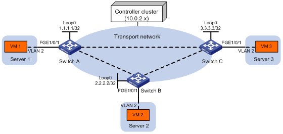
Configuration procedure
1. Configure IP addresses and unicast routing settings:
# Assign IP addresses to interfaces, as shown in Figure 18. (Details not shown.)
# Configure a unicast routing protocol on all transport network switches (Switches A through D). (Details not shown.)
2. Deploy a VXLAN IP gateway on the transport network. (Details not shown.)
3. Configure Switch A:
# Enable L2VPN.
<SwitchA> system-view
[SwitchA] l2vpn enable
# Enable Layer 2 forwarding for VXLANs.
[SwitchA] undo vxlan ip-forwarding
# Configure active TCP connection settings.
[SwitchA] ovsdb server tcp ip 10.0.2.15 port 6632
# Enable the OVSDB server.
[SwitchA] ovsdb server enable
# Enable the OVSDB VTEP service.
[SwitchA] vtep enable
# Specify the site-facing interface FortyGigE 1/0/1 as a VTEP access port.
[SwitchA] interface fortygige 1/0/1
[SwitchA-FortyGigE1/0/1] vtep access port
[SwitchA-FortyGigE1/0/1] quit
4. Configure Switch B:
# Enable L2VPN.
<SwitchB> system-view
[SwitchB] l2vpn enable
# Enable Layer 2 forwarding for VXLANs.
[SwitchB] undo vxlan ip-forwarding
# Configure active TCP connection settings.
[SwitchB] ovsdb server tcp ip 10.0.2.15 port 6632
# Enable the OVSDB server.
[SwitchB] ovsdb server enable
# Enable the OVSDB VTEP service.
[SwitchB] vtep enable
# Specify the site-facing interface FortyGigE 1/0/1 as a VTEP access port.
[SwitchB] interface fortygige 1/0/1
[SwitchB-FortyGigE1/0/1] vtep access port
[SwitchB-FortyGigE1/0/1] quit
5. Configure Switch C:
# Enable L2VPN.
<SwitchC> system-view
[SwitchC] l2vpn enable
# Enable Layer 2 forwarding for VXLANs.
[SwitchC] undo vxlan ip-forwarding
# Configure active TCP connection settings.
[SwitchC] ovsdb server tcp ip 10.0.2.15 port 6632
# Enable the OVSDB server.
[SwitchC] ovsdb server enable
# Enable the OVSDB VTEP service.
[SwitchC] vtep enable
# Specify the site-facing interface FortyGigE 1/0/1 as a VTEP access port.
[SwitchC] interface fortygige 1/0/1
[SwitchC-FortyGigE1/0/1] vtep access port
[SwitchC-FortyGigE1/0/1] quit
6. Configure VXLAN settings on the controller. (Details not shown.)
Verifying the configuration
1. Verify the VXLAN settings on the VTEPs. This example uses Switch A.
# Verify that the VXLAN tunnel interfaces on the VTEP are up.
[SwitchA] display interface tunnel
Tunnel1
Current state: UP
Line protocol state: UP
Description: Tunnel1 Interface
Bandwidth: 64kbps
Maximum transmission unit: 1464
Internet protocol processing: Disabled
Last clearing of counters: Never
Tunnel source 1.1.1.1, destination 2.2.2.2
Tunnel protocol/transport UDP_VXLAN/IP
Last 300 seconds input rate: 0 bytes/sec, 0 bits/sec, 0 packets/sec
Last 300 seconds output rate: 0 bytes/sec, 0 bits/sec, 0 packets/sec
Input: 0 packets, 0 bytes, 0 drops
Output: 0 packets, 0 bytes, 0 drops
# Verify that the VXLAN tunnels have been assigned to the VXLAN.
[SwitchA] display l2vpn vsi verbose
VSI Name: evpn2014
VSI Index : 0
VSI State : Up
MTU : 1500
Bandwidth : -
Broadcast Restrain : -
Multicast Restrain : -
Unknown Unicast Restrain: -
MAC Learning : Enabled
MAC Table Limit : -
Drop Unknown : -
Flooding : Enabled
VXLAN ID : 10
Tunnels:
Tunnel Name Link ID State Type Flooding proxy
Tunnel1 0x5000001 Up Manual Disabled
Tunnel2 0x5000002 Up Manual Disabled
ACs:
AC Link ID State
FGE1/0/1 srv2 0 Up
# Verify that the VTEP has learned the MAC addresses of remote VMs.
<SwitchA> display l2vpn mac-address
MAC Address State VSI Name Link ID/Name Aging
00ea-1100-0001 Dynamic SDN_VSI_8008 0 Aging
0023-89aa-2f0a Dynamic SDN_VSI_8008 Tunnel257 Aging
3c8c-404e-dd46 Dynamic SDN_VSI_8008 Tunnel257 Aging
--- 3 mac address(es) found ---
2. Verify that VM 1, VM 2, and VM 3 can ping each other. (Details not shown.)
Flood proxy VXLAN configuration example
Network requirements
As shown in Figure 19:
· Configure the controller cluster to deploy VXLAN 10 to Switch A, Switch B, and Switch C to provide Layer 2 connectivity for the VMs across the network sites.
· Enable flood proxy for VXLAN 10.
· Use the MAC address entries issued by the controller to direct traffic forwarding on Switch A, Switch B, and Switch C.
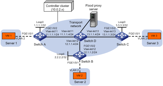
Configuration procedure
1. Configure IP addresses and unicast routing settings:
# Assign IP addresses to interfaces, as shown in Figure 19. (Details not shown.)
# Configure OSPF on all transport network switches (Switches A through D). (Details not shown.)
2. Configure Switch A:
# Enable L2VPN.
<SwitchA> system-view
[SwitchA] l2vpn enable
# Configure active TCP connection settings.
[SwitchA] ovsdb server tcp ip 10.0.2.15 port 6632
# Enable the OVSDB server.
[SwitchA] ovsdb server enable
# Enable the OVSDB VTEP service.
[SwitchA] vtep enable
# Assign an IP address to Loopback 0.
[SwitchA] interface loopback 0
[SwitchA-LoopBack0] ip address 1.1.1.1 255.255.255.255
[SwitchA-LoopBack0] quit
# Specify the IP address of Loopback 0 as the global source address for VXLAN tunnels.
[SwitchA] tunnel global source-address 1.1.1.1
# Specify the site-facing interface FortyGigE 1/0/1 as a VTEP access port.
[SwitchA] interface fortygige 1/0/1
[SwitchA-FortyGigE1/0/1] vtep access port
[SwitchA-FortyGigE1/0/1] quit
# Disable remote-MAC address learning.
[SwitchA] vxlan tunnel mac-learning disable
# Enable flood proxy on multicast VXLAN tunnels.
[SwitchA] vxlan tunnel service node
3. Configure Switch B:
# Enable L2VPN.
<SwitchB> system-view
[SwitchB] l2vpn enable
# Configure active TCP connection settings.
[SwitchB] ovsdb server tcp ip 10.0.2.15 port 6632
# Enable the OVSDB server.
[SwitchB] ovsdb server enable
# Enable the OVSDB VTEP service.
[SwitchB] vtep enable
# Assign an IP address to Loopback 0.
[SwitchB] interface loopback 0
[SwitchB-LoopBack0] ip address 2.2.2.2 255.255.255.255
[SwitchB-LoopBack0] quit
# Specify the IP address of Loopback 0 as the global source address for VXLAN tunnels.
[SwitchB] tunnel global source-address 2.2.2.2
# Specify the site-facing interface FortyGigE 1/0/1 as a VTEP access port.
[SwitchB] interface fortygige 1/0/1
[SwitchB-FortyGigE1/0/1] vtep access port
[SwitchB-FortyGigE1/0/1] quit
# Disable remote-MAC address learning.
[SwitchB] vxlan tunnel mac-learning disable
# Enable flood proxy on multicast VXLAN tunnels.
[SwitchB] vxlan tunnel service node
4. Configure Switch C:
# Enable L2VPN.
<SwitchC> system-view
[SwitchC] l2vpn enable
# Configure active TCP connection settings.
[SwitchC] ovsdb server tcp ip 10.0.2.15 port 6632
# Enable the OVSDB server.
[SwitchC] ovsdb server enable
# Enable the OVSDB VTEP service.
[SwitchC] vtep enable
# Assign an IP address to Loopback 0.
[SwitchC] interface loopback 0
[SwitchC-LoopBack0] ip address 3.3.3.3 255.255.255.255
[SwitchC-LoopBack0] quit
# Specify the IP address of Loopback 0 as the global source address for VXLAN tunnels.
[SwitchC] tunnel global source-address 3.3.3.3
# Specify the site-facing interface FortyGigE 1/0/1 as a VTEP access port.
[SwitchC] interface fortygige 1/0/1
[SwitchC-FortyGigE1/0/1] vtep access port
[SwitchC-FortyGigE1/0/1] quit
# Disable remote-MAC address learning.
[SwitchC] vxlan tunnel mac-learning disable
# Enable flood proxy on multicast VXLAN tunnels.
[SwitchC] vxlan tunnel service node
5. Configure VXLAN settings on the controller, and configure the flood proxy server. (Details not shown.)
Verifying the configuration
1. Verify the VXLAN settings on the VTEPs. This example uses Switch A.
# Verify that the VXLAN tunnel interfaces on the VTEP are up.
[SwitchA] display interface tunnel 1
Tunnel1
Current state: UP
Line protocol state: UP
Description: Tunnel1 Interface
Bandwidth: 64 kbps
Maximum transmission unit: 1464
Internet protocol processing: Disabled
Last clearing of counters: Never
Tunnel source 1.1.1.1, destination 2.2.2.2
Tunnel protocol/transport UDP_VXLAN/IP
# Verify that the VXLAN tunnels have been assigned to the VXLAN, and flood proxy has been enabled on the multicast VXLAN tunnel.
[SwitchA] display l2vpn vsi verbose
VSI Name: evpn2014
VSI Index : 0
VSI State : Up
MTU : 1500
Bandwidth : -
Broadcast Restrain : -
Multicast Restrain : -
Unknown Unicast Restrain: -
MAC Learning : Enabled
MAC Table Limit : -
Drop Unknown : -
Flooding : Enabled
VXLAN ID : 10
Tunnels:
Tunnel Name Link ID State Type Flooding proxy
Tunnel1 0x5000001 Up Manual Disabled
Tunnel2 0x5000002 Up Manual Disabled
Tunnel3 0x5000003 Up Manual Enabled
ACs:
AC Link ID State
FGE1/0/1 srv2 0 Up
# Verify that the VTEP has obtained the MAC addresses of remote VMs from the controller.
<SwitchA> display l2vpn mac-address
MAC Address State VSI Name Link ID/Name Aging
cc3e-5f9c-6cdb Static evpn2014 Tunnel1 NotAging
cc3e-5f9c-23dc Static evpn2014 Tunnel2 NotAging
--- 2 mac address(es) found ---
2. Verify that VM 1, VM 2, and VM 3 can ping each other. (Details not shown.)
