- Table of Contents
- Related Documents
-
| Title | Size | Download |
|---|---|---|
| 09-MCE configuration | 491.33 KB |
Associating a VPN instance with an interface
Configuring route related attributes for a VPN instance
Configuring routing between an MCE and a VPN site
Configuring routing between an MCE and a PE
Displaying and maintaining MCE
Configuring the MCE that uses OSPF to advertise VPN routes to the PE
Configuring the MCE that uses EBGP to advertise VPN routes to the PE
IPv6 MCE configuration task list
Associating a VPN instance with an interface
Configuring route related attributes for a VPN instance
Configuring routing between an MCE and a VPN site
Configuring routing between an MCE and a PE
Displaying and maintaining IPv6 MCE·
IPv6 MCE configuration example
Configuring MCE
This chapter describes MCE configuration. For information about the related routing protocols, see Layer 3—IP Routing Configuration Guide.
MPLS L3VPN overview
MPLS L3VPN is a L3VPN technology used to interconnect geographically dispersed VPN sites. MPLS L3VPN uses BGP to advertise VPN routes and uses MPLS to forward VPN packets over a service provider backbone.
MPLS L3VPN provides flexible networking modes, excellent scalability, and convenient support for MPLS TE.
Basic MPLS L3VPN architecture
Figure 1 Basic MPLS L3VPN architecture
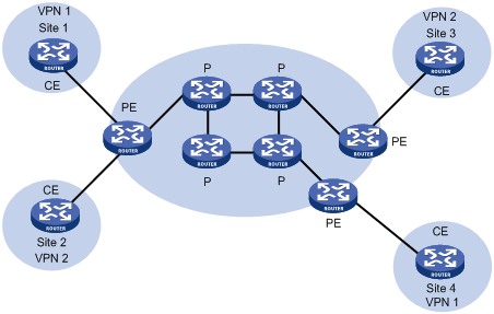
A basic MPLS L3VPN architecture has the following types of devices:
· Customer edge device—A CE device resides on a customer network and has one or more interfaces directly connected to a service provider network. It does not support VPN or MPLS.
· Provider edge device—A PE device resides at the edge of a service provider network and connects to one or more CEs. All MPLS VPN services are processed on PEs.
· Provider device—A P device is a core device on a service provider network. It is not directly connected to any CE. A P device has only basic MPLS forwarding capability and does not handle VPN routing information.
MPLS L3VPN concepts
Site
A site has the following features:
· A site is a group of IP systems with IP connectivity that does not rely on any service provider network.
· The classification of a site depends on the topology relationship of the devices, rather than the geographical positions, though the devices at a site are, in most cases, adjacent to each other geographically.
· The devices at a site can belong to multiple VPNs, which means that a site can belong to multiple VPNs.
· A site is connected to a provider network through one or more CEs. A site can contain multiple CEs, but a CE can belong to only one site.
Sites connected to the same provider network can be classified into different sets by policies. Only the sites in the same set can access each other through the provider network. Such a set is called a VPN.
VPN instance
VPN instances, also called virtual routing and forwarding (VRF) instances, implement route isolation, data independence, and data security for VPNs.
A VPN instance has the following components:
· A separate Label Forwarding Information Base (LFIB).
· An IP routing table.
· Interfaces bound to the VPN instance.
· VPN instance administration information, including route distinguishers (RDs), route targets (RTs), and route filtering policies.
To associate a site with a VPN instance, bind the VPN instance to the PE's interface connected to the site. A site can be associated with only one VPN instance, and different sites can associate with the same VPN instance. A VPN instance contains the VPN membership and routing rules of associated sites.
Address space overlapping
Each VPN independently manages its address space.
The address spaces of VPNs might overlap. For example, if both VPN 1 and VPN 2 use the addresses on subnet 10.110.10.0/24, address space overlapping occurs.
VPN-IPv4 address
BGP cannot process overlapping VPN address spaces. For example, if both VPN 1 and VPN 2 use the subnet 10.110.10.0/24 and each advertise a route destined for the subnet, BGP selects only one of them, resulting in the loss of the other route.
Multiprotocol BGP (MP-BGP) can solve this problem by advertising VPN-IPv4 prefixes.
Figure 2 VPN-IPv4 address structure
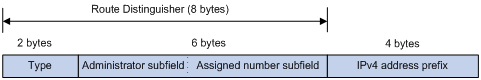
As shown in Figure 2, a VPN-IPv4 address consists of 12 bytes. The first eight bytes represent the RD, followed by a four-byte IPv4 prefix. The RD and the IPv4 prefix form a unique VPN-IPv4 prefix.
An RD can be in one of the following formats:
· When the Type field is 0, the Administrator subfield occupies two bytes, the Assigned number subfield occupies four bytes, and the RD format is 16-bit AS number:32-bit user-defined number. For example, 100:1.
· When the Type field is 1, the Administrator subfield occupies four bytes, the Assigned number subfield occupies two bytes, and the RD format is 32-bit IPv4 address:16-bit user-defined number. For example, 172.1.1.1:1.
· When the Type field is 2, the Administrator subfield occupies four bytes, the Assigned number subfield occupies two bytes, and the RD format is 32-bit AS number:16-bit user-defined number, where the minimum value of the AS number is 65536. For example, 65536:1.
To guarantee global uniqueness for an RD, do not set the Administrator subfield to any private AS number or private IP address.
Route target attribute
MPLS L3VPN uses route target community attributes to control the advertisement of VPN routing information. A VPN instance on a PE supports the following types of route target attributes:
· Export target attribute—A PE sets the export target attribute for VPN-IPv4 routes learned from directly connected sites before advertising them to other PEs.
· Import target attribute—A PE checks the export target attribute of VPN-IPv4 routes received from other PEs. If the export target attribute matches the import target attribute of a VPN instance, the PE adds the routes to the routing table of the VPN instance.
Route target attributes define which sites can receive VPN-IPv4 routes, and from which sites a PE can receive routes.
Like RDs, route target attributes can be one of the following formats:
· 16-bit AS number:32-bit user-defined number. For example, 100:1.
· 32-bit IPv4 address:16-bit user-defined number. For example, 172.1.1.1:1.
· 32-bit AS number:16-bit user-defined number, where the minimum value of the AS number is 65536. For example, 65536:1.
MCE overview
BGP/MPLS VPN transmits private network data through MPLS tunnels over the public network. However, the traditional MPLS L3VPN architecture requires that each VPN instance use an exclusive CE to connect to a PE, as shown in Figure 1.
A private network is typically divided into multiple VPNs to isolate services. To meet these requirements, you can configure a CE for each VPN, which increases device expense and maintenance costs. Or, you can configure multiple VPNs to use the same CE and the same routing table, which sacrifices data security.
You can use the Multi-VPN Instance CE (MCE) function in multi-VPN networks. MCE allows you to bind each VPN to a VLAN interface. The MCE creates and maintains a separate routing table for each VPN. This separates the forwarding paths of packets of different VPNs and, in conjunction with the PE, can correctly advertise the routes of each VPN to the peer PE, ensuring the normal transmission of VPN packets over the public network.
Figure 3 Network diagram for the MCE function
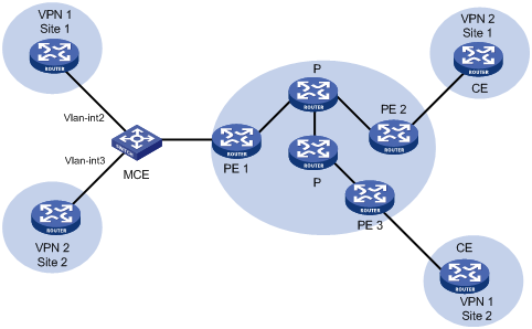
As shown in Figure 3, the MCE device creates a routing table for each VPN. VLAN interface 2 binds to VPN 1 and VLAN-interface 3 binds to VPN 2. When receiving a route, the MCE device determines the source of the routing information according to the number of the receiving interface, and then adds it to the corresponding routing table. The MCE connects to PE 1 through a trunk link that permits packets tagged with VLAN 2 or VLAN 3. PE 1 determines the VPN that a received packet belongs to according to the VLAN tag of the packet, and sends the packet through the corresponding tunnel.
You can configure static routes, RIP, OSPF, IS-IS, EBGP, or IBGP between an MCE and a VPN site and between an MCE and a PE.
|
|
NOTE: To implement dynamic IP assignment for DHCP clients in private networks, you can configure DHCP server or DHCP relay agent on the MCE. When the MCE functions as the DHCP server, the IP addresses assigned to different private networks cannot overlap. |
MCE configuration task list
|
Tasks at a glance |
|
|
1. (Required.) Creating a VPN instance 1. (Required.) Associating a VPN instance with an interface 2. (Optional.) Configuring route related attributes for a VPN instance |
|
|
Configuring routing on an MCE: · (Required.) Configuring routing between an MCE and a VPN site · (Required.) Configuring routing between an MCE and a PE |
Configuring VPN instances
VPN instances isolate VPN routes from public network routes and routes among VPNs. You must configure VPN instances for an MCE networking scheme.
Creating a VPN instance
A VPN instance is a collection of the VPN membership and routing rules of its associated site. A VPN instance might not correspond to one VPN.
To create and configure a VPN instance:
|
Step |
Command |
Remarks |
|
1. Enter system view. |
system-view |
N/A |
|
2. Create a VPN instance and enter VPN instance view. |
ip vpn-instance vpn-instance-name |
By default, no VPN instance is created. |
|
3. Configure an RD for the VPN instance. |
route-distinguisher route-distinguisher |
By default, no RD is specified for a VPN instance. |
|
4. (Optional.) Configure a description for the VPN instance. |
description text |
By default, no description is configured for a VPN instance. |
|
5. (Optional.) Configure a VPN ID for the VPN instance. |
vpn-id vpn-id |
By default, no VPN ID is configured for a VPN instance. |
Associating a VPN instance with an interface
After creating and configuring a VPN instance, associate the VPN instance with the MCE's interface connected to the site and the interface connected to the PE.
To associate a VPN instance with an interface:
|
Step |
Command |
Remarks |
|
1. Enter system view. |
system-view |
N/A |
|
2. Enter interface view. |
interface interface-type interface-number |
N/A |
|
3. Associate a VPN instance with the interface. |
ip binding vpn-instance vpn-instance-name |
By default, an interface is not associated with a VPN instance. The ip binding vpn-instance command deletes the IP address of the current interface. You must re-configure an IP address for the interface after configuring the command. |
Configuring route related attributes for a VPN instance
VPN routes are controlled and advertised on a PE by using the following process:
1. When a VPN route learned from a site gets redistributed into BGP, BGP associates it with a route target extended community attribute list, which is typically the export target attribute of the VPN instance associated with the site.
2. The VPN instance determines which routes it can accept and redistribute according to the import-extcommunity in the route target.
3. The VPN instance determines how to change the route target attributes for routes to be advertised according to the export-extcommunity in the route target.
To configure route related attributes for a VPN instance:
|
Step |
Command |
Remarks |
|
1. Enter system view. |
system-view |
N/A |
|
2. Enter VPN instance view or IPv4 VPN view. |
·
Enter VPN instance view: · Enter IPv4 VPN view: a. ip vpn-instance vpn-instance-name b. address-family ipv4 |
An IPv4 VPN prefers the configurations in IPv4 VPN view over the configurations in VPN instance view. |
|
3. Configure route targets. |
vpn-target vpn-target&<1-8> [ both | export-extcommunity | import-extcommunity ] |
By default, no route targets are configured. |
|
4. Set the maximum number of active routes. |
routing-table limit number { warn-threshold | simply-alert } |
By default, the number of active routes in a VPN instance is not limited. Setting the maximum number of active routes for a VPN instance can prevent the PE from learning too many routes. |
|
5. Apply an import routing policy. |
import route-policy route-policy |
By default, all routes matching the import target attribute are accepted. The specified routing policy must have been created. For information about routing policies, see Layer 3—IP Routing Configuration Guide. |
|
6. Apply an export routing policy. |
export route-policy route-policy |
By default, routes to be advertised are not filtered. The specified routing policy must have been created. For information about routing policies, see Layer 3—IP Routing Configuration Guide. |
Configuring routing on an MCE
MCE implements service isolation through route isolation. MCE routing configuration includes the following:
· MCE-VPN site routing configuration.
· MCE-PE routing configuration.
On the PE, disable routing loop detection to avoid route loss during route calculation, and disable route redistribution between routing protocols to save system resources.
Before you configure routing on an MCE, complete the following tasks:
· Configure VPN instances, and bind the VPN instances with the interfaces connected to the VPN sites and the PE.
· Configure the link layer and network layer protocols on related interfaces to ensure IP connectivity.
Configuring routing between an MCE and a VPN site
You can configure static routing, RIP, OSPF, IS-IS, EBGP, or IBGP between an MCE and a VPN site.
Configuring static routing between an MCE and a VPN site
An MCE can reach a VPN site through a static route. Static routing on a traditional CE is globally effective and does not support address overlapping among VPNs. An MCE supports binding a static route to a VPN instance, so that the static routes of different VPN instances can be isolated from each other.
To configure a static route to a VPN site:
|
Step |
Command |
Remarks |
|
1. Enter system view. |
system-view |
N/A |
|
2. Configure a static route for a VPN instance. |
ip route-static vpn-instance s-vpn-instance-name dest-address { mask-length | mask } { interface-type interface-number [ next-hop-address ] | next-hop-address [ public ] [ track track-entry-number ] | vpn-instance d-vpn-instance-name next-hop-address [ track track-entry-number ] } [ permanent ] [ preference preference-value ] [ tag tag-value ] [ description description-text ] |
By default, no static route is configured. Perform this configuration on the MCE. On the VPN site, configure a common static route. |
|
3. (Optional.) Configure the default preference for static routes. |
ip route-static default-preference default-preference-value |
The default preference is 60. |
Configuring RIP between an MCE and a VPN site
A RIP process belongs to the public network or a single VPN instance. If you create a RIP process without binding it to a VPN instance, the process belongs to the public network. Binding RIP processes to VPN instances can isolate routes of different VPNs. For more information about RIP, see Layer 3—IP Routing Configuration Guide.
To configure RIP between an MCE and a VPN site:
|
Step |
Command |
Remarks |
|
1. Enter system view. |
system-view |
N/A |
|
2. Create a RIP process for a VPN instance and enter RIP view. |
rip [ process-id ] vpn-instance vpn-instance-name |
Perform this configuration on the MCE. On a VPN site, create a common RIP process. |
|
3. Enable RIP on the interface attached to the specified network. |
network network-address |
By default, RIP is disabled on an interface. |
|
4. Redistribute remote site routes advertised by the PE into RIP. |
import-route protocol [ process-id ] [ allow-ibgp ] [ cost cost | route-policy route-policy-name | tag tag ] * |
By default, no route is redistributed into RIP. |
|
5. (Optional.) Configure the default cost value for the redistributed routes. |
default cost value |
The default cost is 0. |
Configuring OSPF between an MCE and a VPN site
An OSPF process belongs to the public network or a single VPN instance. If you create an OSPF process without binding it to a VPN instance, the process belongs to the public network.
Binding OSPF processes to VPN instances can isolate routes of different VPNs. For more information about OSPF, see Layer 3—IP Routing Configuration Guide.
To configure OSPF between an MCE and a VPN site:
|
Step |
Command |
Remarks |
|
1. Enter system view. |
system-view |
N/A |
|
2. Create an OSPF process for a VPN instance and enter OSPF view. |
ospf [ process-id | router-id router-id | vpn-instance vpn-instance-name ] * |
Perform this configuration on the MCE. On a VPN site, create a common OSPF process. An OSPF process bound to a VPN instance does not use the public network router ID configured in system view. Therefore, configure a router ID for the OSPF process. An OSPF process can belong to only one VPN instance, but one VPN instance can use multiple OSPF processes to advertise VPN routes. |
|
3. (Optional.) Configure the OSPF domain ID. |
domain-id domain-id [ secondary ] |
The default domain ID is 0. Perform this configuration on the MCE. All OSPF processes of the same VPN instance must be configured with the same OSPF domain ID to ensure correct route advertisement. |
|
4. (Optional.) Configure the type codes of OSPF extended community attributes. |
ext-community-type { domain-id type-code1 | router-id type-code2 | route-type type-code3 } |
The defaults are as follows: · 0x0005 for Domain ID. · 0x0107 for Router ID. · 0x0306 for Route Type. |
|
5. (Optional.) Configure the external route tag for imported VPN routes. |
route-tag tag-value |
By default, no route tag is configured. In some networks, a VPN might be connected to multiple MCEs. When one MCE advertises the routes learned from BGP to the VPN, the other MCEs might learn the routes, resulting in routing loops. To avoid such routing loops, you can configure route tags for VPN instances on an MCE. As a best practice, configure the same route tag for the same VPN on the MCEs. |
|
6. Redistribute remote site routes advertised by the PE into OSPF. |
import-route protocol [ process-id | all-processes | allow-ibgp ] [ cost cost | route-policy route-policy-name | tag tag | type type ] * |
By default, no routes are redistributed into OSPF. |
|
7. (Optional.) Configure OSPF to redistribute the default route. |
default-route-advertise summary cost cost |
By default, OSPF does not redistribute the default route. This command redistributes the default route in a Type-3 LSA. The MCE advertises the default route to the site. |
|
8. Create an OSPF area and enter OSPF area view. |
area area-id |
By default, no OSPF area is created. |
|
9. Enable OSPF on the interface attached to the specified network in the area. |
network ip-address wildcard-mask |
By default, an interface neither belongs to any area nor runs OSPF. |
Configuring IS-IS between an MCE and a VPN site
An IS-IS process belongs to the public network or a single VPN instance. If you create an IS-IS process without binding it to a VPN instance, the process belongs to the public network.
Binding IS-IS processes to VPN instances can isolate routes of different VPNs. For more information about IS-IS, see Layer 3—IP Routing Configuration Guide.
To configure IS-IS between an MCE and a VPN site:
|
Step |
Command |
Remarks |
|
1. Enter system view. |
system-view |
N/A |
|
2. Create an IS-IS process for a VPN instance and enter IS-IS view. |
isis [ process-id ] vpn-instance vpn-instance-name |
Perform this configuration on the MCE. On a VPN site, configure a common IS-IS process. |
|
3. Configure a network entity title. |
network-entity net |
By default, no NET is configured. |
|
4. Redistribute remote site routes advertised by the PE into IS-IS. |
import-route protocol [ process-id | all-processes | allow-ibgp ] [ cost cost | cost-type { external | internal } | [ level-1 | level-1-2 | level-2 ] | route-policy route-policy-name | tag tag ] * |
By default, IS-IS does not redistribute routes from any other routing protocol. If you do not specify the route level in the command, the command redistributes routes to the level-2 routing table by default. |
|
5. Return to system view. |
quit |
N/A |
|
6. Enter interface view. |
interface interface-type interface-number |
N/A |
|
7. Enable the IS-IS process on the interface. |
isis enable [ process-id ] |
By default, no IS-IS process is enabled. |
Configuring EBGP between an MCE and a VPN site
To run EBGP between an MCE and a VPN site, you must configure a BGP peer for each VPN instance on the MCE, and redistribute the IGP routes of each VPN instance on the VPN site.
You can configure filtering policies to filter received routes and advertised routes.
1. Configure the MCE:
Routes redistributed from OSPF to BGP have their OSPF attributes removed. To enable BGP to distinguish routes redistributed from different OSPF domains, you must enable the redistributed routes to carry the OSPF domain ID by configuring the domain-id command in OSPF view. The domain ID is added to BGP VPN routes as an extended community attribute.
To configure the MCE:
|
Step |
Command |
Remarks |
|
1. Enter system view. |
system-view |
N/A |
|
2. Enter BGP view. |
bgp as-number |
N/A |
|
3. Enter BGP-VPN instance view. |
ip vpn-instance vpn-instance-name |
N/A |
|
4. Configure an EBGP peer. |
peer { group-name | ip-address [ mask-length ] } as-number as-number |
By default, no BGP peer is configured. |
|
5. Enter BGP-VPN IPv4 unicast address family view. |
address-family ipv4 [ unicast ] |
N/A |
|
6. Enable BGP to exchange IPv4 unicast routes with the peer. |
peer { group-name | ip-address [ mask-length ] } enable |
By default, BGP does not exchange IPv4 unicast routes with any peer. |
|
7. Allow the local AS number to appear in the AS_PATH attribute of routes received from the peer, and set the maximum number of repetitions. |
peer { group-name | ip-address [ mask-length ] } allow-as-loop [ number ] |
By default, BGP discards incoming route updates that contain the local AS number. BGP detects routing loops by examining AS numbers. The routing information the MCE advertises to a site carries the local AS number. Therefore, the route updates that the MCE receives from the site also include the local AS number. This causes the MCE to be unable to receive the route updates. In this case, you must configure this command to allow routing loops. |
|
8. Redistribute remote site routes advertised by the PE into BGP. |
import-route protocol [ { process-id | all-processes } [ med med-value | route-policy route-policy-name ] * ] |
By default, no routes are redistributed into BGP. |
|
9. (Optional.) Configure filtering of advertised routes. |
filter-policy { acl-number | prefix-list prefix-list-name } export [ protocol process-id ] |
By default, BGP does not filter advertised routes. |
|
10. (Optional.) Configure filtering of received routes. |
filter-policy { acl-number | prefix-list prefix-list-name } import |
By default, BGP does not filter received routes. |
2. Configure a VPN site:
|
Step |
Command |
Remarks |
|
1. Enter system view. |
system-view |
N/A |
|
2. Enter BGP view. |
bgp as-number |
N/A |
|
3. Configure the MCE as an EBGP peer. |
peer { group-name | ip-address [ mask-length ] } as-number as-number |
N/A |
|
4. Enter BGP-VPN IPv4 unicast address family view. |
address-family ipv4 [ unicast ] |
N/A |
|
5. Enable BGP to exchange IPv4 unicast routes with the peer. |
peer { group-name | ip-address [ mask-length ] } enable |
By default, BGP does not exchange IPv4 unicast routes with any peer. |
|
6. Redistribute the IGP routes of the VPN into BGP. |
import-route protocol [ { process-id | all-processes } [ med med-value | route-policy route-policy-name ] * ] |
By default, no routes are redistributed into BGP. A VPN site must advertise the VPN network addresses it can reach to the connected MCE. |
Configuring IBGP between MCE and VPN site
To run IBGP between an MCE and a VPN site, you must configure a BGP peer for each VPN instance on the MCE, and redistribute the IGP routes of each VPN instance on the VPN site.
1. Configure the MCE:
|
Step |
Command |
Remarks |
|
1. Enter system view. |
system-view |
N/A |
|
2. Enter BGP view. |
bgp as-number |
N/A |
|
3. Enter BGP-VPN instance view. |
ip vpn-instance vpn-instance-name |
N/A |
|
4. Configure an IBGP peer. |
peer { group-name | ip-address [ mask-length ] } as-number as-number |
N/A |
|
5. Enter BGP-VPN IPv4 unicast address family view. |
address-family ipv4 [ unicast ] |
N/A |
|
6. Enable BGP to exchange IPv4 unicast routes with the peer. |
peer { group-name | ip-address [ mask-length ] } enable |
By default, BGP does not exchange IPv4 unicast routes with any peer. |
|
7. (Optional.) Configure the system to be the RR, and specify the peer as the client of the RR. |
peer { group-name | ip-address [ mask-length ] } reflect-client |
By default, no RR or RR client is configured. After you configure a VPN site as an IBGP peer, the MCE does not advertise the BGP routes learned from the VPN site to other IBGP peers, including VPNv4 peers. The MCE advertises routes learned from a VPN site only when you configure the VPN site as a client of the RR (the MCE). |
|
8. Redistribute remote site routes advertised by the PE into BGP. |
import-route protocol [ process-id | all-processes ] [ med med-value | route-policy route-policy-name ] * |
By default, no routes are redistributed into BGP. |
|
9. (Optional.) Configure filtering of advertised routes. |
filter-policy { acl-number | prefix-list prefix-list-name } export [ protocol process-id ] |
By default, BGP does not filter advertised routes. |
|
10. (Optional.) Configure filtering of received routes. |
filter-policy { acl-number | prefix-list prefix-list-name } import |
By default, BGP does not filter received routes. |
2. Configure a VPN site:
|
Step |
Command |
Remarks |
|
1. Enter system view. |
system-view |
N/A |
|
2. Enter BGP view. |
bgp as-number |
N/A |
|
3. Configure the MCE as an IBGP peer. |
peer { group-name | ip-address [ mask-length ] } as-number as-number |
N/A |
|
4. Enter BGP-VPN IPv4 unicast address family view. |
address-family ipv4 [ unicast ] |
N/A |
|
5. Enable BGP to exchange IPv4 unicast routes with the peer. |
peer { group-name | ip-address [ mask-length ] } enable |
By default, BGP does not exchange IPv4 unicast routes with any peer. |
|
6. Redistribute the IGP routes of the VPN into BGP. |
import-route protocol [ { process-id | all-processes } [ med med-value | route-policy route-policy-name ] * ] |
By default, no routes are redistributed into BGP. A VPN site must advertise VPN network addresses to the connected MCE. |
Configuring routing between an MCE and a PE
MCE-PE routing configuration includes the following tasks:
· Binding the MCE-PE interfaces to VPN instances.
· Performing route configurations.
· Redistributing VPN routes into the routing protocol running between the MCE and the PE.
Perform the following configurations on the MCE. For more information about configuring the PE, see the documentation for the PE.
Configuring static routing between an MCE and a PE
|
Step |
Command |
Remarks |
|
1. Enter system view. |
system-view |
N/A |
|
2. Configure a static route for a VPN instance. |
ip route-static vpn-instance s-vpn-instance-name dest-address { mask-length | mask } { interface-type interface-number [ next-hop-address ] | next-hop-address [ public ] [ track track-entry-number ] | vpn-instance d-vpn-instance-name next-hop-address [ track track-entry-number ] } [ permanent ] [ preference preference-value ] [ tag tag-value ] [ description description-text ] |
By default, no static route is configured. |
|
3. (Optional.) Configure the default preference for static routes. |
ip route-static default-preference default-preference-value |
The default preference is 60. |
Configuring RIP between an MCE and a PE
|
Step |
Command |
Remarks |
|
1. Enter system view. |
system-view |
N/A |
|
2. Create a RIP process for a VPN instance and enter RIP view. |
rip [ process-id ] vpn-instance vpn-instance-name |
N/A |
|
3. Enable RIP on the interface attached to the specified network. |
network network-address |
By default, RIP is disabled on an interface. |
|
4. Redistribute the VPN routes. |
import-route protocol [ process-id | all-processes | allow-ibgp ] [ cost cost | route-policy route-policy-name | tag tag ] * |
By default, no routes are redistributed into RIP. |
|
5. (Optional.) Configure the default cost for redistributed routes. |
default cost value |
The default cost is 0. |
Configuring OSPF between an MCE and a PE
|
Step |
Command |
Remarks |
|
1. Enter system view. |
system-view |
N/A |
|
2. Create an OSPF process for a VPN instance and enter OSPF view. |
ospf [ process-id | router-id router-id | vpn-instance vpn-instance-name ] * |
N/A |
|
3. Disable routing loop detection. |
vpn-instance-capability simple |
By default, routing loop detection is enabled. You must disable routing loop detection for an OSPF VRF process on the MCE. Otherwise, the MCE does not receive OSPF routes from the PE. |
|
4. (Optional.) Configure the OSPF domain ID. |
domain-id domain-id [ secondary ] |
The default domain ID is 0. |
|
5. (Optional.) Configure the type codes of OSPF extended community attributes. |
ext-community-type { domain-id type-code1 | router-id type-code2 | route-type type-code3 } |
The defaults are as follows: · 0x0005 for Domain ID. · 0x0107 for Router ID. · 0x0306 for Route Type. |
|
6. (Optional.) Configure the external route tag for imported VPN routes. |
route-tag tag-value |
By default, no route tag is configured. In some networks, a VPN might be connected to multiple MCEs. When one MCE advertises the routes learned from BGP to the VPN, the other MCEs might learn the routes, resulting in routing loops. To avoid such routing loops, you can configure route tags for VPN instances on an MCE. As a best practice, configure the same route tag for the same VPN on the MCEs. |
|
7. Redistribute the VPN routes. |
import-route protocol [ process-id | all-processes | allow-ibgp ] [ cost cost | route-policy route-policy-name | tag tag | type type ] * |
By default, no routes are redistributed into OSPF. |
|
8. (Optional.) Configure OSPF to redistribute the default route. |
default-route-advertise summary cost cost |
By default, OSPF does not redistribute the default route. This command redistributes the default route in a Type-3 LSA. The MCE advertises the default route to the PE. |
|
9. (Optional.) Configure filtering of advertised routes. |
filter-policy { acl-number | prefix-list prefix-list-name } export [ protocol [ process-id ] ] |
By default, redistributed routes are not filtered. |
|
10. (Optional.) Configure the default parameters for redistributed routes (cost, route number, tag, and type). |
default { cost cost | tag tag | type type } * |
The default cost is 1, the default tag is 1, and default type of redistributed routes is Type-2. |
|
11. Create an OSPF area and enter OSPF area view. |
area area-id |
By default, no OSPF area is created. |
|
12. Enable OSPF on the interface attached to the specified network in the area. |
network ip-address wildcard-mask |
By default, an interface neither belongs to any area nor runs OSPF. |
Configuring IS-IS between an MCE and a PE
|
Step |
Command |
Remarks |
|
1. Enter system view. |
system-view |
N/A |
|
2. Create an IS-IS process for a VPN instance and enter IS-IS view. |
isis [ process-id ] vpn-instance vpn-instance-name |
N/A |
|
3. Configure a network entity title. |
network-entity net |
By default, no NET is configured. |
|
4. Redistribute VPN routes. |
import-route protocol [ process-id | all-processes | allow-ibgp ] [ cost cost | cost-type { external | internal } | [ level-1 | level-1-2 | level-2 ] | route-policy route-policy-name | tag tag ] * |
By default, IS-IS does not redistribute routes from any other routing protocol. If you do not specify the route level in the command, the command redistributes routes to the level-2 routing table by default. |
|
5. (Optional.) Configure filtering of advertised routes. |
filter-policy { acl-number | prefix-list prefix-list-name | route-policy route-policy-name } export [ protocol [ process-id ] ] |
By default, IS-IS does not filter advertised routes. |
|
6. Return to system view. |
quit |
N/A |
|
7. Enter interface view. |
interface interface-type interface-number |
N/A |
|
8. Enable the IS-IS process on the interface. |
isis enable [ process-id ] |
By default, no IS-IS process is enabled. |
Configuring EBGP between an MCE and a PE
|
Step |
Command |
Remarks |
|
1. Enter system view. |
system-view |
N/A |
|
2. Enter BGP view. |
bgp as-number |
N/A |
|
3. Enter BGP-VPN instance view. |
ip vpn-instance vpn-instance-name |
N/A |
|
4. Configure the PE as an EBGP peer. |
peer { group-name | ip-address [ mask-length ] } as-number as-number |
N/A |
|
5. Enter BGP-VPN IPv4 unicast address family view. |
address-family ipv4 [ unicast ] |
N/A |
|
6. Enable BGP to exchange IPv4 unicast routes with the peer. |
peer { group-name | ip-address [ mask-length ] } enable |
By default, BGP does not exchange IPv4 unicast routes with any peer. |
|
7. Redistribute the VPN routes of the VPN site. |
import-route protocol [ process-id | all-processes ] [ med med-value | route-policy route-policy-name ] * |
By default, no routes are redistributed into BGP. |
|
8. (Optional.) Configure filtering of advertised routes. |
filter-policy { acl-number | prefix-list prefix-list-name } export [ protocol process-id ] |
By default, BGP does not filter advertised routes. |
|
9. (Optional.) Configure filtering of received routes. |
filter-policy { acl-number | prefix-list prefix-list-name } import |
By default, BGP does not filter received routes. |
Configuring IBGP between an MCE and a PE
|
Step |
Command |
Remarks |
|
1. Enter system view. |
system-view |
N/A |
|
2. Enter BGP view. |
bgp as-number |
N/A |
|
3. Enter BGP-VPN instance view. |
ip vpn-instance vpn-instance-name |
N/A |
|
4. Configure the PE as an IBGP peer. |
peer { group-name | ip-address [ mask-length ] } as-number as-number |
N/A |
|
5. Enter BGP-VPN IPv4 unicast address family view. |
address-family ipv4 [ unicast ] |
N/A |
|
6. Enable BGP to exchange IPv4 unicast routes with the peer. |
peer { group-name | ip-address [ mask-length ] } enable |
By default, BGP does not exchange IPv4 unicast routes with any peer. |
|
7. Redistribute the VPN routes of the VPN site. |
import-route protocol [ process-id | all-processes ] [ med med-value | route-policy route-policy-name ] * |
By default, no routes are redistributed into BGP. |
|
8. (Optional.) Configure filtering of advertised routes. |
filter-policy { acl-number | prefix-list prefix-list-name } export [ protocol process-id ] |
By default, BGP does not filter advertised routes. |
|
9. (Optional.) Configure filtering of received routes. |
filter-policy { acl-number | prefix-list prefix-list-name } import |
By default, BGP does not filter received routes. |
Displaying and maintaining MCE
Execute display commands in any view.
|
Task |
Command |
|
Display VPN instance information. |
display ip vpn-instance [ instance-name vpn-instance-name ] |
|
Display BGP peer group information for a VPN instance. |
display bgp group ipv4 [ unicast ] vpn-instance vpn-instance-name [ group-name group-name ] |
|
Display BGP peer information for a VPN instance (in standalone mode). |
display bgp peer ipv4 [ unicast ] vpn-instance vpn-instance-name [ ip-address mask-length | { ip-address | group-name group-name } log-info | [ [ ip-address ] verbose ] [ standby slot slot-number ] ] |
|
Display BGP peer information for a VPN instance (in IRF mode). |
display bgp peer ipv4 [ unicast ] vpn-instance vpn-instance-name [ ip-address mask-length | { ip-address | group-name group-name } log-info | [ [ ip-address ] verbose ] [ standby chassis chassis-number slot slot-number ] ] |
For other MCE displaying and maintaining commands, such as the commands for displaying VPN routing tables and maintaining VPN routing sessions, see Layer 3—IP Routing Command Reference.
For more information about the display bgp group ipv4 and display bgp peer ipv4 commands, see Layer 3—IP Routing Command Reference.
MCE configuration examples
Configuring the MCE that uses OSPF to advertise VPN routes to the PE
Network requirements
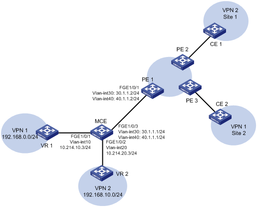
As shown in Figure 4, the MCE device is connected to VPN 1 through VLAN-interface 10 and is connected with VPN 2 through VLAN-interface 20. OSPF runs in VPN 2.
Configure the MCE device to separate routes from different VPNs and to advertise the VPN routes to PE 1 through OSPF.
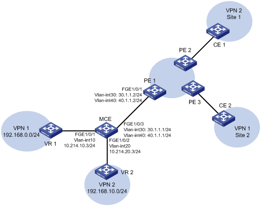
Configuration procedure
Assume that the system name of the MCE device is MCE, the system names of the edge devices of VPN 1 and VPN 2 are VR1 and VR2, respectively, and the system name of PE 1 is PE1.
1. Configure the VPN instances on the MCE and PE 1:
# On the MCE, configure VPN instances vpn1 and vpn2, and specify an RD and route targets for each VPN instance.
<MCE> system-view
[MCE] ip vpn-instance vpn1
[MCE-vpn-instance-vpn1] route-distinguisher 10:1
[MCE-vpn-instance-vpn1] vpn-target 10:1
[MCE-vpn-instance-vpn1] quit
[MCE] ip vpn-instance vpn2
[MCE-vpn-instance-vpn2] route-distinguisher 20:1
[MCE-vpn-instance-vpn2] vpn-target 20:1
[MCE-vpn-instance-vpn2] quit
# Create VLAN 10, add FortyGigE 1/0/1 to VLAN 10, and create VLAN-interface 10.
[MCE] vlan 10
[MCE-vlan10] port fortygige 1/0/1
[MCE-vlan10] quit
# Bind VLAN-interface 10 with VPN instance vpn1, and configure an IP address for VLAN-interface 10.
[MCE] interface vlan-interface 10
[MCE-Vlan-interface10] ip binding vpn-instance vpn1
[MCE-Vlan-interface10] ip address 10.214.10.3 24
[MCE-Vlan-interface10] quit
# Configure VLAN 20, add FortyGigE 1/0/2 to VLAN 20, bind VLAN-interface 20 with VPN instance vpn2, and specify an IP address for VLAN-interface 20.
[MCE] vlan 20
[MCE-vlan20] port fortygige 1/0/2
[MCE-vlan20] quit
[MCE] interface vlan-interface 20
[MCE-Vlan-interface20] ip binding vpn-instance vpn2
[MCE-Vlan-interface20] ip address 10.214.20.3 24
[MCE-Vlan-interface20] quit
# On PE 1, configure VPN instances vpn1 and vpn2, and specify an RD and route targets for each VPN instance.
<PE1> system-view
[PE1] ip vpn-instance vpn1
[PE1-vpn-instance-vpn1] route-distinguisher 10:1
[PE1-vpn-instance-vpn1] vpn-target 10:1
[PE1-vpn-instance-vpn1] quit
[PE1] ip vpn-instance vpn2
[PE1-vpn-instance-vpn2] route-distinguisher 20:1
[PE1-vpn-instance-vpn2] vpn-target 20:1
[PE1-vpn-instance-vpn2] quit
2. Configure routing between the MCE and VPN sites:
The MCE is connected to VPN 1 directly, and no routing protocol is enabled in VPN 1. Therefore, you can configure static routes.
# On VR 1, assign IP address 10.214.10.2/24 to the interface connected to MCE and 192.168.0.1/24 to the interface connected to VPN 1. Add ports to VLANs correctly. (Details not shown.)
# On VR 1, configure a default route with the next hop being 10.214.10.3.
<VR1> system-view
[VR1] ip route-static 0.0.0.0 0.0.0.0 10.214.10.3
# On the MCE, configure a static route to 192.168.0.0/24, specify the next hop as 10.214.10.2, and bind the static route with VPN instance vpn1.
[MCE] ip route-static vpn-instance vpn1 192.168.0.0 24 10.214.10.2
# On the MCE, display the routing information maintained for VPN instance vpn1.
[MCE] display ip routing-table vpn-instance vpn1
Destinations : 13 Routes : 13
Destination/Mask Proto Pre Cost NextHop Interface
0.0.0.0/32 Direct 0 0 127.0.0.1 InLoop0
10.214.10.0/24 Direct 0 0 10.214.10.3 Vlan10
10.214.10.0/32 Direct 0 0 10.214.10.3 Vlan10
10.214.10.3/32 Direct 0 0 127.0.0.1 InLoop0
10.214.10.255/32 Direct 0 0 10.214.10.3 Vlan10
127.0.0.0/8 Direct 0 0 127.0.0.1 InLoop0
127.0.0.0/32 Direct 0 0 127.0.0.1 InLoop0
127.0.0.1/32 Direct 0 0 127.0.0.1 InLoop0
127.255.255.255/32 Direct 0 0 127.0.0.1 InLoop0
192.168.0.0/24 Static 60 0 10.214.10.2 Vlan10
224.0.0.0/4 Direct 0 0 0.0.0.0 NULL0
224.0.0.0/24 Direct 0 0 0.0.0.0 NULL0
255.255.255.255/32 Direct 0 0 127.0.0.1 InLoop0
The output shows that the MCE has a static route for VPN instance vpn1.
# Run OSPF in VPN 2. Create OSPF process 20 and bind it with VPN instance vpn2 on the MCE, so that the MCE can learn the routes of VPN 2 and add them to the routing table of the VPN instance vpn2.
[MCE] ospf 2 vpn-instance vpn2
# Advertise subnet 10.214.20.0.
[MCE-ospf-2] area 0
[MCE-ospf-2-area-0.0.0.0] network 10.214.20.0 0.0.0.255
[MCE-ospf-2-area-0.0.0.0] quit
[MCE-ospf-2] quit
# On VR 2, assign IP address 10.214.20.2/24 to the interface connected to MCE and 192.168.10.1/24 to the interface connected to VPN 2. (Details not shown.)
# Configure OSPF process 2, and advertise subnets 192.168.10.0 and 10.214.20.0.
<VR2> system-view
[VR2] ospf 2
[VR2-ospf-2] area 0
[VR2-ospf-2-area-0.0.0.0] network 192.168.10.0 0.0.0.255
[VR2-ospf-2-area-0.0.0.0] network 10.214.20.0 0.0.0.255
[VR2-ospf-2-area-0.0.0.0] quit
[VR2-ospf-2] quit
# On the MCE, display the routing information maintained for VPN instance vpn2.
[MCE] display ip routing-table vpn-instance vpn2
Destinations : 13 Routes : 13
Destination/Mask Proto Pre Cost NextHop Interface
0.0.0.0/32 Direct 0 0 127.0.0.1 InLoop0
10.214.20.0/24 Direct 0 0 10.214.20.3 Vlan20
10.214.20.0/32 Direct 0 0 10.214.20.3 Vlan20
10.214.20.3/32 Direct 0 0 127.0.0.1 InLoop0
10.214.20.255/32 Direct 0 0 10.214.20.3 Vlan20
127.0.0.0/8 Direct 0 0 127.0.0.1 InLoop0
127.0.0.0/32 Direct 0 0 127.0.0.1 InLoop0
127.0.0.1/32 Direct 0 0 127.0.0.1 InLoop0
127.255.255.255/32 Direct 0 0 127.0.0.1 InLoop0
192.168.10.0/24 OSPF 10 2 10.214.20.2 Vlan20
224.0.0.0/4 Direct 0 0 0.0.0.0 NULL0
224.0.0.0/24 Direct 0 0 0.0.0.0 NULL0
255.255.255.255/32 Direct 0 0 127.0.0.1 InLoop0
The output shows that the MCE has learned the private routes of VPN 2. The MCE maintains the routes of VPN 1 and those of VPN2 in two different routing tables. In this way, routes from different VPNs are separated.
3. Configure routing between the MCE and PE 1:
# The MCE uses FortyGigE 1/0/3 to connect to PE's port FortyGigE 1/0/1. Configure the two ports as trunk ports, and configure them to permit packets carrying VLAN tags 30 and 40 to pass.
[MCE] interface fortygige 1/0/3
[MCE-FortyGigE1/0/3] port link-type trunk
[MCE-FortyGigE1/0/3] port trunk permit vlan 30 40
[MCE-FortyGigE1/0/3] quit
# Configure FortyGigE 1/0/1 on the PE.
[PE1] interface fortygige 1/0/1
[PE1-FortyGigE1/0/1] port link-type trunk
[PE1-FortyGigE1/0/1] port trunk permit vlan 30 40
[PE1-FortyGigE1/0/1] quit
# On the MCE, create VLAN 30 and VLAN-interface 30, bind the VLAN interface with VPN instance vpn1, and configure an IP address for the VLAN interface.
[MCE] vlan 30
[MCE-vlan30] quit
[MCE] interface vlan-interface 30
[MCE-Vlan-interface30] ip binding vpn-instance vpn1
[MCE-Vlan-interface30] ip address 30.1.1.1 24
[MCE-Vlan-interface30] quit
# On the MCE, create VLAN 40 and VLAN-interface 40, bind the VLAN interface with VPN instance vpn2, and configure an IP address for the VLAN interface.
[MCE] vlan 40
[MCE-vlan40] quit
[MCE] interface vlan-interface 40
[MCE-Vlan-interface40] ip binding vpn-instance vpn2
[MCE-Vlan-interface40] ip address 40.1.1.1 24
[MCE-Vlan-interface40] quit
# On PE 1, create VLAN 30 and VLAN-interface 30, bind the VLAN interface with VPN instance vpn1, and configure an IP address for the VLAN interface.
[PE1] vlan 30
[PE1-vlan30] quit
[PE1] interface vlan-interface 30
[PE1-Vlan-interface30] ip binding vpn-instance vpn1
[PE1-Vlan-interface30] ip address 30.1.1.2 24
[PE1-Vlan-interface30] quit
# On PE 1, create VLAN 40 and VLAN-interface 40, bind the VLAN interface with VPN instance vpn2, and configure an IP address for the VLAN interface.
[PE1] vlan 40
[PE1-vlan40] quit
[PE1] interface vlan-interface 40
[PE1-Vlan-interface40] ip binding vpn-instance vpn2
[PE1-Vlan-interface40] ip address 40.1.1.2 24
[PE1-Vlan-interface40] quit
# Configure the IP address of the interface Loopback 0 as 101.101.10.1 for the MCE and as 100.100.10.1 for PE 1. Specify the loopback interface address as the router ID for the MCE and PE 1. (Details not shown.)
# Enable OSPF process 10 on the MCE, bind the process to VPN instance vpn1, disable OSPF routing loop detection, and set the domain ID to 10.
[MCE] ospf 10 router-id 101.101.10.1 vpn-instance vpn1
[MCE-ospf-10] vpn-instance-capability simple
[MCE-ospf-10] domain-id 10
# On the MCE, advertise subnet 30.1.1.0 in area 0, and redistribute the static route of VPN 1.
[MCE-ospf-10] area 0
[MCE-ospf-10-area-0.0.0.0] network 30.1.1.0 0.0.0.255
[MCE-ospf-10-area-0.0.0.0] quit
[MCE-ospf-10] import-route static
# On PE 1, enable OSPF process 10, bind the process with VPN instance vpn1, set the domain ID to 10, and advertise subnet 30.1.1.0 in area 0.
[PE1] ospf 10 router-id 100.100.10.1 vpn-instance vpn1
[PE1-ospf-10] domain-id 10
[PE1-ospf-10] area 0
[PE1-ospf-10-area-0.0.0.0] network 30.1.1.0 0.0.0.255
[PE1-ospf-10-area-0.0.0.0] quit
[PE1-ospf-10] quit
# Use similar procedures to configure OSPF process 20 between MCE and PE 1 and redistribute VPN 2's routing information. (Details not shown.)
Verifying the configuration
# On PE 1, display the routing information for VPN 1. The output shows that the static route of VPN 1 has been redistributed to the OSPF routing table of PE 1.
[PE1] display ip routing-table vpn-instance vpn1
Destinations : 13 Routes : 13
Destination/Mask Proto Pre Cost NextHop Interface
0.0.0.0/32 Direct 0 0 127.0.0.1 InLoop0
30.1.1.0/24 Direct 0 0 30.1.1.2 Vlan30
30.1.1.0/32 Direct 0 0 30.1.1.2 Vlan30
30.1.1.2/32 Direct 0 0 127.0.0.1 InLoop0
30.1.1.255/32 Direct 0 0 30.1.1.2 Vlan30
127.0.0.0/8 Direct 0 0 127.0.0.1 InLoop0
127.0.0.0/32 Direct 0 0 127.0.0.1 InLoop0
127.0.0.1/32 Direct 0 0 127.0.0.1 InLoop0
127.255.255.255/32 Direct 0 0 127.0.0.1 InLoop0
192.168.0.0/24 OSPF 150 1 30.1.1.1 Vlan30
224.0.0.0/4 Direct 0 0 0.0.0.0 NULL0
224.0.0.0/24 Direct 0 0 0.0.0.0 NULL0
255.255.255.255/32 Direct 0 0 127.0.0.1 InLoop0
# On PE 1, display the routing information for VPN 2. The output shows that the routes of OSPF process 2 in VPN 2 have been redistributed to the OSPF routing table of PE 1.
[PE1] display ip routing-table vpn-instance vpn2
Destinations : 13 Routes : 13
Destination/Mask Proto Pre Cost NextHop Interface
0.0.0.0/32 Direct 0 0 127.0.0.1 InLoop0
40.1.1.0/24 Direct 0 0 40.1.1.2 Vlan40
40.1.1.0/32 Direct 0 0 40.1.1.2 Vlan40
40.1.1.2/32 Direct 0 0 127.0.0.1 InLoop0
40.1.1.255/32 Direct 0 0 40.1.1.2 Vlan40
127.0.0.0/8 Direct 0 0 127.0.0.1 InLoop0
127.0.0.0/32 Direct 0 0 127.0.0.1 InLoop0
127.0.0.1/32 Direct 0 0 127.0.0.1 InLoop0
127.255.255.255/32 Direct 0 0 127.0.0.1 InLoop0
192.168.10.0/24 OSPF 150 1 40.1.1.1 Vlan40
224.0.0.0/4 Direct 0 0 0.0.0.0 NULL0
224.0.0.0/24 Direct 0 0 0.0.0.0 NULL0
255.255.255.255/32 Direct 0 0 127.0.0.1 InLoop0
Now, the routing information for the two VPNs has been redistributed into the routing tables on PE 1.
Configuring the MCE that uses EBGP to advertise VPN routes to the PE
Network requirements
As shown in Figure 5, configure the MCE to advertise the routes of VPNs 1 and 2 to PE 1, so that the sites of each VPN can communicate with each other over the MPLS backbone.
Run OSPF in both VPN 1 and VPN 2. Run EBGP between the MCE and PE 1.
Configuration procedure
1. Create VPN instances on the MCE and PE 1, and bind the VPN instances with VLAN interfaces. For the configuration procedure, see "Configure the VPN instances on the MCE and PE 1:."
2. Configure routing between the MCE and VPN sites:
# Enable an OSPF process on the devices in the two VPNs, and advertise the subnets. (Details not shown.)
# Configure OSPF on the MCE, and bind OSPF process 10 with VPN instance vpn1 to learn the routes of VPN 1.
<MCE> system-view
[MCE] ospf 10 router-id 10.10.10.1 vpn-instance vpn1
[MCE-ospf-10] area 0
[MCE-ospf-10-area-0.0.0.0] network 10.214.10.0 0.0.0.255
[MCE-ospf-10-area-0.0.0.0] quit
[MCE-ospf-10] quit
# Display the routing table of VPN 1 on the MCE.
[MCE] display ip routing-table vpn-instance vpn1
Destinations : 13 Routes : 13
Destination/Mask Proto Pre Cost NextHop Interface
0.0.0.0/32 Direct 0 0 127.0.0.1 InLoop0
10.214.10.0/24 Direct 0 0 10.214.10.3 Vlan10
10.214.10.0/32 Direct 0 0 10.214.10.3 Vlan10
10.214.10.3/32 Direct 0 0 127.0.0.1 InLoop0
10.214.10.255/32 Direct 0 0 10.214.10.3 Vlan10
127.0.0.0/8 Direct 0 0 127.0.0.1 InLoop0
127.0.0.0/32 Direct 0 0 127.0.0.1 InLoop0
127.0.0.1/32 Direct 0 0 127.0.0.1 InLoop0
127.255.255.255/32 Direct 0 0 127.0.0.1 InLoop0
192.168.0.0/24 OSPF 10 2 10.214.10.2 Vlan10
224.0.0.0/4 Direct 0 0 0.0.0.0 NULL0
224.0.0.0/24 Direct 0 0 0.0.0.0 NULL0
255.255.255.255/32 Direct 0 0 127.0.0.1 InLoop0
The output shows that the MCE has learned the private route of VPN 1 through OSPF process 10.
# On the MCE, bind OSPF process 20 with VPN instance vpn2 to learn the routes of VPN 2. The configuration procedure is similar to that for OSPF process 10.
The output shows that the MCE has learned the private route of VPN 2 through OSPF.
[MCE] display ip routing-table vpn-instance vpn2
Destinations : 13 Routes : 13
Destination/Mask Proto Pre Cost NextHop Interface
0.0.0.0/32 Direct 0 0 127.0.0.1 InLoop0
10.214.20.0/24 Direct 0 0 10.214.20.3 Vlan20
10.214.20.0/32 Direct 0 0 10.214.20.3 Vlan20
10.214.20.3/32 Direct 0 0 127.0.0.1 InLoop0
10.214.20.255/32 Direct 0 0 10.214.20.3 Vlan20
127.0.0.0/8 Direct 0 0 127.0.0.1 InLoop0
127.0.0.0/32 Direct 0 0 127.0.0.1 InLoop0
127.0.0.1/32 Direct 0 0 127.0.0.1 InLoop0
127.255.255.255/32 Direct 0 0 127.0.0.1 InLoop0
192.168.10.0/24 OSPF 10 2 10.214.20.2 Vlan20
224.0.0.0/4 Direct 0 0 0.0.0.0 NULL0
224.0.0.0/24 Direct 0 0 0.0.0.0 NULL0
255.255.255.255/32 Direct 0 0 127.0.0.1 InLoop0
3. Configure routing between the MCE and PE 1:
# Configure the ports between the MCE and PE 1 as trunk ports. The configuration procedure is similar to that described in "Configure routing between the MCE and PE 1:." (Details not shown.)
# Enable BGP in AS 100 on the MCE, enter the BGP-VPN instance view of VPN instance vpn1, and specify the EBGP peer PE 1 in AS 200.
[MCE] bgp 100
[MCE-bgp] ip vpn-instance vpn1
[MCE-bgp-vpn1] peer 30.1.1.2 as-number 200
# Activate the EBGP VPNv4 peer PE 1, and redistribute routing information from OSPF process 10 to BGP.
[MCE-bgp-vpn1] address-family ipv4
[MCE-bgp-ipv4-vpn1] peer 30.1.1.2 enable
[MCE-bgp-ipv4-vpn1] import-route ospf 10
# On PE 1, enable BGP in AS 200, and specify the MCE as its EBGP peer.
[PE1] bgp 200
[PE1-bgp] ip vpn-instance vpn1
[PE1-bgp-vpn1] peer 30.1.1.1 as-number 100
[PE1-bgp-vpn1] address-family ipv4
[PE1-bgp-ipv4-vpn1] peer 30.1.1.1 enable
[PE1-bgp-ipv4-vpn1] quit
[PE1-bgp-vpn1] quit
[PE1-bgp] quit
# Use similar procedures to configure VPN 2 settings on MCE and PE 1. (Details not shown.)
Verifying the configuration
# Display the routing information for VPN 1 on PE 1.
[PE1] display ip routing-table vpn-instance vpn1
Destinations : 13 Routes : 13
Destination/Mask Proto Pre Cost NextHop Interface
0.0.0.0/32 Direct 0 0 127.0.0.1 InLoop0
30.1.1.0/24 Direct 0 0 30.1.1.2 Vlan30
30.1.1.0/32 Direct 0 0 30.1.1.2 Vlan30
30.1.1.2/32 Direct 0 0 127.0.0.1 InLoop0
30.1.1.255/32 Direct 0 0 30.1.1.2 Vlan30
127.0.0.0/8 Direct 0 0 127.0.0.1 InLoop0
127.0.0.0/32 Direct 0 0 127.0.0.1 InLoop0
127.0.0.1/32 Direct 0 0 127.0.0.1 InLoop0
127.255.255.255/32 Direct 0 0 127.0.0.1 InLoop0
192.168.0.0/24 BGP 255 3 30.1.1.1 Vlan30
224.0.0.0/4 Direct 0 0 0.0.0.0 NULL0
224.0.0.0/24 Direct 0 0 0.0.0.0 NULL0
255.255.255.255/32 Direct 0 0 127.0.0.1 InLoop0
# Display the routing information for VPN 2 on PE 1.
[PE1] display ip routing-table vpn-instance vpn2
Destinations : 13 Routes : 13
Destination/Mask Proto Pre Cost NextHop Interface
0.0.0.0/32 Direct 0 0 127.0.0.1 InLoop0
40.1.1.0/24 Direct 0 0 40.1.1.2 Vlan40
40.1.1.0/32 Direct 0 0 40.1.1.2 Vlan40
40.1.1.2/32 Direct 0 0 127.0.0.1 InLoop0
40.1.1.255/32 Direct 0 0 40.1.1.2 Vlan40
127.0.0.0/8 Direct 0 0 127.0.0.1 InLoop0
127.0.0.0/32 Direct 0 0 127.0.0.1 InLoop0
127.0.0.1/32 Direct 0 0 127.0.0.1 InLoop0
127.255.255.255/32 Direct 0 0 127.0.0.1 InLoop0
192.168.10.0/24 BGP 255 3 40.1.1.1 Vlan40
224.0.0.0/4 Direct 0 0 0.0.0.0 NULL0
224.0.0.0/24 Direct 0 0 0.0.0.0 NULL0
255.255.255.255/32 Direct 0 0 127.0.0.1 InLoop0
Now, the MCE has redistributed the OSPF routes of the two VPN instances into the EBGP routing tables of PE 1.
Configuring IPv6 MCE
Overview
In IPv6 MPLS L3VPN networks, IPv6 MCE advertises IPv6 routes between internal networks and PEs and forwards IPv6 packets. The fundamentals of IPv6 MCE are the same as those of MCE. For more information, see "MCE overview."
IPv6 MCE configuration task list
|
Tasks at a glance |
|
|
(Required.) Creating a VPN instance (Required.) Associating a VPN instance with an interface (Optional.) Configuring route related attributes for a VPN instance |
|
|
Configuring routing on an MCE: (Required.) Configuring routing between an MCE and a VPN site (Required.) Configuring routing between an MCE and a PE |
Configuring VPN instances
By configuring VPN instances on a PE, you isolate not only VPN routes from public network routes, but also routes between VPNs. You must configure VPN instances for an MCE networking scheme.
Creating a VPN instance
A VPN instance is a collection of the VPN membership and routing rules of its associated site. A VPN instance might correspond to more than one VPN.
To create and configure a VPN instance:
|
Step |
Command |
Remarks |
|
1. Enter system view. |
system-view |
N/A |
|
2. Create a VPN instance and enter VPN instance view. |
ip vpn-instance vpn-instance-name |
By default, no VPN instances exist. |
|
3. Configure an RD for the VPN instance. |
route-distinguisher route-distinguisher |
By default, no RD is configured for a VPN instance. |
|
4. (Optional.) Configure a description for the VPN instance. |
description text |
By default, no description is configured for a VPN instance. The description should contain the VPN instance's related information, such as its relationship with a certain VPN. |
|
5. (Optional.) Set an ID for the VPN instance. |
vpn-id vpn-id |
By default, no ID is configured for a VPN instance. |
Associating a VPN instance with an interface
After creating and configuring a VPN instance, associate the VPN instance with the interface connected to the CE.
To associate a VPN instance with an interface:
|
Step |
Command |
Remarks |
|
1. Enter system view. |
system-view |
N/A |
|
2. Enter interface view. |
interface interface-type interface-number |
N/A |
|
3. Associate a VPN instance with the interface. |
ip binding vpn-instance vpn-instance-name |
By default, an interface is associated with no VPN instance and belongs to the public network. The ip binding vpn-instance command clears the IPv6 address of the interface. Therefore, reconfigure an IP address for the interface after configuring this command. |
Configuring route related attributes for a VPN instance
VPN routes are controlled and advertised on a PE by using the following process:
1. When a VPN route learned from a site gets redistributed into BGP, BGP associates it with a route target extended community attribute list. The list is typically the export target attribute of the VPN instance associated with the site.
2. The VPN instance determines which routes it can accept and redistribute according to the import-extcommunity in the route target.
3. The VPN instance determines how to change the route target attributes for routes to be advertised according to the export-extcommunity in the route target.
To configure related attributes for a VPN instance:
|
Step |
Command |
Remarks |
|
1. Enter system view. |
system-view |
N/A |
|
2. Enter VPN instance view or IPv6 VPN view. |
·
Enter VPN instance view: · Enter IPv6 VPN view: a. ip vpn-instance vpn-instance-name b. address-family ipv6 |
Configurations made in VPN instance view apply to both IPv4 VPN and IPv6 VPN. IPv6 VPN prefers the configurations in IPv6 VPN view over the configurations in VPN instance view. |
|
3. Configure route targets. |
vpn-target vpn-target&<1-8> [ both | export-extcommunity | import-extcommunity ] |
By default, no route targets are configured. |
|
4. Set the maximum number of active routes. |
routing-table limit number { warn-threshold | simply-alert } |
By default, the number of active routes in a VPN instance is not limited. Setting the maximum number of active routes for a VPN instance can prevent the PE from storing too many routes. |
|
5. Apply an import routing policy. |
import route-policy route-policy |
By default, all routes matching the import target attribute are accepted. Make sure the routing policy already exists. Otherwise, the device does not filter received routes. For information about routing policies, see Layer 3—IP Routing Configuration Guide. |
|
6. Apply an export routing policy. |
export route-policy route-policy |
By default, routes to be advertised are not filtered. Make sure the routing policy already exists. Otherwise, the device does not filter routes to be advertised. For information about routing policies, see Layer 3—IP Routing Configuration Guide. |
|
7. Apply a tunnel policy to the VPN instance. |
tnl-policy tunnel-policy-name |
By default, only one tunnel is selected (no load balancing) in this order: LSP tunnel and CRLSP tunnel. The specified tunnel policy must have been created. For information about tunnel policies, see "Configuring tunnel policies." |
Configuring routing on an MCE
An MCE implements service isolation through route isolation. MCE routing configuration includes the following:
· MCE-VPN site routing configuration.
· MCE-PE routing configuration.
On a PE in an MCE network environment, perform the following tasks:
· Disable routing loop detection to avoid route loss during route calculation.
· Disable route redistribution between routing protocols to save system resources.
Before you configure routing on an MCE, perform the following tasks:
· On the MCE, configure VPN instances, and bind the VPN instances to the interfaces connected to the VPN sites and those connected to the PE.
· Configure the link layer and network layer protocols on related interfaces to ensure IP connectivity.
Configuring routing between an MCE and a VPN site
You can configure IPv6 static routing, RIPng, OSPFv3, IPv6 IS-IS, or EBGP between an MCE and a VPN site.
Configuring IPv6 static routing between an MCE and a VPN site
An MCE can reach a VPN site through an IPv6 static route. IPv6 static routing on a traditional CE is globally effective and does not support address overlapping among VPNs. An MCE supports binding an IPv6 static route with an IPv6 VPN instance, so that the IPv6 static routes of different IPv6 VPN instances can be isolated from each other.
To configure IPv6 static routing between an MCE and a VPN site:
|
Step |
Command |
Remarks |
|
1. Enter system view. |
system-view |
N/A |
|
2. Configure an IPv6 static route for an IPv6 VPN instance. |
ipv6 route-static vpn-instance s-vpn-instance-name ipv6-address prefix-length { interface-type interface-number [ next-hop-address ] | nexthop-address [ public ] | vpn-instance d-vpn-instance-name nexthop-address } [ permanent ] [ preference preference-value ] [ tag tag-value ] [ description description-text ] |
By default, no IPv6 static routes are configured. Perform this configuration on the MCE. On a VPN site, configure normal IPv6 static routes. |
|
3. (Optional.) Configure the default preference for IPv6 static routes. |
ipv6 route-static default-preference default-preference-value |
The default preference for IPv6 static routes is 60. |
Configuring RIPng between an MCE and a VPN site
A RIPng process belongs to the public network or a single IPv6 VPN instance. If you create a RIPng process without binding it to an IPv6 VPN instance, the process belongs to the public network. By configuring RIPng process-to-IPv6 VPN instance bindings on a MCE, you allow routes of different VPNs to be exchanged between the MCE and the sites through different RIPng processes, ensuring the separation and security of IPv6 VPN routes.
For more information about RIPng, see Layer 3—IP Routing Configuration Guide.
To configure RIPng between an MCE and a VPN site:
|
Step |
Command |
Remarks |
|
1. Enter system view. |
system-view |
N/A |
|
2. Create a RIPng process for a VPN instance and enter RIPng view. |
ripng [ process-id ] vpn-instance vpn-instance-name |
Perform this configuration on the MCE. On a VPN site, configure normal RIPng. |
|
3. Redistribute remote site routes advertised by the PE. |
import-route protocol [ process-id ] [ allow-ibgp ] [ cost cost | route-policy route-policy-name ] * |
By default, no routes are redistributed into RIPng. |
|
4. (Optional.) Configure the default cost value for the redistributed routes. |
default cost value |
The default cost is 0. |
|
5. Return to system view. |
quit |
N/A |
|
6. Enter interface view. |
interface interface-type interface-number |
N/A |
|
7. Enable RIPng on the interface. |
ripng process-id enable |
By default, RIPng is disabled. |
Configuring OSPFv3 between an MCE and a VPN site
An OSPFv3 process belongs to the public network or a single IPv6 VPN instance. If you create an OSPFv3 process without binding it to an IPv6 VPN instance, the process belongs to the public network.
By configuring OSPFv3 process-to-IPv6 VPN instance bindings on a MCE, you allow routes of different IPv6 VPNs to be exchanged between the MCE and the sites through different OSPFv3 processes, ensuring the separation and security of IPv6 VPN routes.
For more information about OSPFv3, see Layer 3—IP Routing Configuration Guide.
To configure OSPFv3 between an MCE and a VPN site:
|
Step |
Command |
Remarks |
|
1. Enter system view. |
system-view |
N/A |
|
2. Create an OSPFv3 process for a VPN instance and enter OSPFv3 view. |
ospfv3 [ process-id | vpn-instance vpn-instance-name ] * |
Perform this configuration on the MCE. On a VPN site, configure common OSPFv3. Deleting a VPN instance also deletes all related OSPFv3 processes. |
|
3. Set the router ID. |
router-id router-id |
N/A |
|
4. (Optional.) Configure the OSPFv3 domain ID. |
domain-id { domain-id [ secondary ] | null } |
The default domain ID is 0. Perform this configuration on the MCE. All OSPFv3 processes of the same VPN instance must be configured with the same OSPFv3 domain ID to ensure correct route advertisement. |
|
5. Redistribute remote site routes advertised by the PE. |
import-route protocol [ process-id | all-processes | allow-ibgp ] [ cost cost | nssa-only | route-policy route-policy-name | tag tag | type type ] * |
By default, no routes are redistributed into OSPFv3. |
|
6. Return to system view. |
quit |
N/A |
|
7. Enter interface view. |
interface interface-type interface-number |
N/A |
|
8. Enable OSPFv3 on the interface. |
ospfv3 process-id area area-id [ instance instance-id ] |
By default, OSPFv3 is disabled on an interface. |
Configuring IPv6 IS-IS between an MCE and a VPN site
An IPv6 IS-IS process belongs to the public network or a single IPv6 VPN instance. If you create an IPv6 IS-IS process without binding it to an IPv6 VPN instance, the process belongs to the public network.
By configuring IPv6 IS-IS process-to-IPv6 VPN instance bindings on a MCE, you allow routes of different IPv6 VPNs to be exchanged between the MCE and the sites through different IPv6 IS-IS processes. This ensures the separation and security of IPv6 VPN routes. For more information about IPv6 IS-IS, see Layer 3—IP Routing Configuration Guide.
To configure IPv6 IS-IS between an MCE and a VPN site:
|
Step |
Command |
Remarks |
|
1. Enter system view. |
system-view |
N/A |
|
2. Create an IPv6 IS-IS process for a VPN instance and enter IS-IS view. |
isis [ process-id ] vpn-instance vpn-instance-name |
Perform this configuration on the MCE. On a VPN site, configure common IPv6 IS-IS. |
|
3. Configure a network entity title for the IS-IS process. |
network-entity net |
By default, no NET is configured. |
|
4. Enable IPv6 for the IS-IS process. |
ipv6 enable |
By default, IPv6 is disabled for an IS-IS process. |
|
5. (Optional.) Redistribute remote site routes advertised by the PE. |
ipv6 import-route protocol [ process-id ] [ allow-ibgp ] [ cost cost | [ level-1 | level-1-2 | level-2 ] | route-policy route-policy-name | tag tag ] * |
By default, no routes are redistributed to IPv6 IS-IS. If you do not specify the route level in the command, redistributed routes are added to the level-2 routing table. |
|
6. Return to system view. |
quit |
N/A |
|
7. Enter interface view. |
interface interface-type interface-number |
N/A |
|
8. Enable the IPv6 IS-IS process on the interface. |
isis ipv6 enable [ process-id ] |
By default, no IPv6 IS-IS process is enabled on the interface. |
Configuring EBGP between an MCE and a VPN site
To use EBGP between an MCE and IPv6 VPN sites, you must configure a BGP peer for each IPv6 VPN instance on the MCE, and redistribute the IGP routes of each VPN instance on the IPv6 VPN sites.
You can configure filtering policies to filter received routes and advertised routes. For more information about IPv6 BGP, see Layer 3—IP Routing Configuration Guide.
1. Configure the MCE:
|
Step |
Command |
Remarks |
|
1. Enter system view. |
system-view |
N/A |
|
2. Enter BGP view. |
bgp as-number |
N/A |
|
3. Enter BGP-VPN instance view. |
ip vpn-instance vpn-instance-name |
N/A |
|
4. Specify an IPv6 BGP peer in an AS. |
peer { group-name | ipv6-address [ prefix-length ] } as-number as-number |
By default, no BGP peers exist. |
|
5. Enter BGP-VPN IPv6 unicast address family view. |
address-family ipv6 [ unicast ] |
N/A |
|
6. Enable BGP to exchange IPv6 unicast routes with the specified peer. |
peer { group-name | ipv6-address [ prefix-length ] } enable |
By default, BGP does not exchange IPv6 unicast routes with any peer. |
|
7. Redistribute remote site routes advertised by the PE. |
import-route protocol [ process-id [ med med-value | route-policy route-policy-name ] * ] |
By default, no route redistribution is configured. |
|
8. (Optional.) Configure filtering of advertised routes. |
filter-policy { acl6-number | prefix-list ipv6-prefix-name } export [ protocol process-id ] |
By default, BGP does not filter advertised routes. |
|
9. (Optional.) Configure filtering of received routes. |
filter-policy { acl6-number | prefix-list ipv6-prefix-name } import |
By default, BGP does not filter received routes. |
2. Configure a VPN site:
|
Step |
Command |
Remarks |
|
1. Enter system view. |
system-view |
N/A |
|
2. Enter BGP view. |
bgp as-number |
N/A |
|
3. Configure the MCE as an EBGP peer. |
peer { group-name | ipv6-address [ prefix-length ] } as-number as-number |
By default, no BGP peers exist. |
|
4. Enter BGP IPv6 unicast address family view. |
address-family ipv6 [ unicast ] |
N/A |
|
5. Enable BGP to exchange IPv6 unicast routes with the specified peer. |
peer { group-name | ipv6-address [ prefix-length ] } enable |
By default, BGP does not exchange IPv6 unicast routes with any peer. |
|
6. Redistribute the IGP routes of the VPN. |
import-route protocol [ process-id [ med med-value | route-policy route-policy-name ] * ] |
By default, no routes are redistributed into BGP. A VPN site must advertise IPv6 VPN network addresses it can reach to the connected MCE. |
Configuring IBGP between an MCE and a VPN site
To use IBGP between an MCE and a VPN site, you must configure a BGP peer for each IPv6 VPN instance on the MCE, and redistribute the IGP routes of each VPN instance on the VPN site.
1. Configure the MCE:
|
Step |
Command |
Remarks |
|
1. Enter system view. |
system-view |
N/A |
|
2. Enter BGP view. |
bgp as-number |
By default, BGP is not enabled. |
|
3. Enter BGP-VPN instance view. |
ip vpn-instance vpn-instance-name |
N/A |
|
4. Configure an IBGP peer. |
peer { group-name | ipv6-address [ prefix-length ] } as-number as-number |
By default, no BGP peers or peer groups exist. |
|
5. Enter BGP-VPN IPv6 unicast address family view. |
address-family ipv6 [ unicast ] |
N/A |
|
6. Enable BGP to exchange IPv6 unicast routes with the peer. |
peer { group-name | ipv6-address [ prefix-length ] } enable |
By default, BGP does not exchange IPv6 unicast routes with any peer. |
|
7. (Optional.) Configure the system to be the RR, and specify the peer as the client of the RR. |
peer { group-name | ipv6-address [ prefix-length ] } reflect-client |
By default, no RR or RR client is configured. After you configure a VPN site as an IBGP peer, the MCE does not advertise the BGP routes learned from the VPN site to other IBGP peers, including VPNv6 peers. The MCE advertises routes learned from a VPN site only when you configure the VPN site as a client of the RR (the MCE). |
|
8. Redistribute remote site routes advertised by the PE into BGP. |
import-route protocol [ process-id [ med med-value | route-policy route-policy-name ] * ] |
By default, no routes are redistributed into BGP. |
|
9. (Optional.) Configure filtering of advertised routes. |
filter-policy { acl6-number | prefix-list ipv6-prefix-name } export [ protocol process-id ] |
By default, BGP does not filter advertised routes. |
|
10. (Optional.) Configure filtering of received routes. |
filter-policy { acl6-number | prefix-list ipv6-prefix-name } import |
By default, BGP does not filter received routes. |
2. Configure a VPN site:
|
Step |
Command |
Remarks |
|
1. Enter system view. |
system-view |
N/A |
|
2. Enter BGP view. |
bgp as-number |
By default, BGP is not enabled. |
|
3. Configure the MCE as an IBGP peer. |
peer { group-name | ipv6-address [ prefix-length ] } as-number as-number |
By default, no BGP peers or peer groups exist. |
|
4. Enter BGP IPv6 unicast address family view. |
address-family ipv6 [ unicast ] |
N/A |
|
5. Enable BGP to exchange IPv6 unicast routes with the peer. |
peer { group-name | ipv6-address [ prefix-length ] } enable |
By default, BGP does not exchange IPv6 unicast routes with any peer. |
|
6. Redistribute the IGP routes of the VPN into BGP. |
import-route protocol [ process-id [ med med-value | route-policy route-policy-name ] * ] |
By default, no routes are redistributed into BGP. A VPN site must advertise VPN network addresses to the connected MCE. |
Configuring routing between an MCE and a PE
MCE-PE routing configuration includes the following tasks:
· Binding the MCE-PE interfaces to IPv6 VPN instances.
· Performing routing configurations.
· Redistributing IPv6 VPN routes into the routing protocol running between the MCE and the PE.
Perform the following configuration tasks on the MCE. For information about configuring the PE, see the documentation for the PE.
Configuring IPv6 static routing between an MCE and a PE
|
Step |
Command |
Remarks |
|
1. Enter system view. |
system-view |
N/A |
|
2. Configure an IPv6 static route for an IPv6 VPN instance. |
ipv6 route-static vpn-instance s-vpn-instance-name ipv6-address prefix-length { interface-type interface-number [ next-hop-address ] | nexthop-address [ public ] | vpn-instance d-vpn-instance-name nexthop-address } [ permanent ] [ preference preference-value ] [ tag tag-value ] [ description description-text ] |
By default, no IPv6 static routes are configured. |
|
3. (Optional.) Set the default preference for IPv6 static routes. |
ipv6 route-static default-preference default-preference-value |
The default value is 60. |
Configuring RIPng between an MCE and a PE
|
Step |
Command |
Remarks |
|
1. Enter system view. |
system-view |
N/A |
|
2. Create a RIPng process for an IPv6 VPN instance and enter RIPng view. |
ripng [ process-id ] vpn-instance vpn-instance-name |
N/A |
|
3. Redistribute VPN routes. |
import-route protocol [ process-id ] [ allow-ibgp ] [ cost cost | route-policy route-policy-name ] * |
By default, no routes are redistributed into RIPng. |
|
4. (Optional.) Configure the default cost value for the redistributed routes. |
default cost value |
The default cost is 0. |
|
5. Return to system view. |
quit |
N/A |
|
6. Enter interface view. |
interface interface-type interface-number |
N/A |
|
7. Enable the RIPng process on the interface. |
ripng process-id enable |
By default, RIPng is disabled on an interface. |
Configuring OSPFv3 between an MCE and a PE
|
Step |
Command |
Remarks |
|
1. Enter system view. |
system-view |
N/A |
|
2. Create an OSPFv3 process for an IPv6 VPN instance and enter OSPFv3 view. |
ospfv3 [ process-id | vpn-instance vpn-instance-name ] * |
N/A |
|
3. Set the router ID. |
router-id router-id |
N/A |
|
4. Disable routing loop detection. |
vpn-instance-capability simple |
By default, routing loop detection is enabled. On an MCE network, you must disable routing loop detection for a VPN OSPFv3 process. Otherwise, the MCE does not receive OSPFv3 routes from the PE. |
|
5. (Optional.) Configure the OSPFv3 domain ID. |
domain-id { domain-id [ secondary ] | null } |
The default domain ID is 0. |
|
6. Redistribute VPN routes. |
import-route protocol [ process-id | all-processes | allow-ibgp ] [ cost cost | nssa-only | route-policy route-policy-name | tag tag | type type ] * |
By default, no routes are redistributed into OSPFv3. |
|
7. (Optional.) Configure filtering of advertised routes. |
filter-policy { acl6-number | prefix-list prefix-list-name } export [ protocol [ process-id ] ] |
By default, redistributed routes are not filtered. |
|
8. (Optional.) Configure the default tag for redistributed routes. |
default tag tag |
The default tag is 1. |
|
9. Return to system view. |
quit |
N/A |
|
10. Enter interface view. |
interface interface-type interface-number |
N/A |
|
11. Enable the OSPFv3 process on the interface. |
ospfv3 process-id area area-id [ instance instance-id ] |
By default, OSPFv3 is disabled on an interface. |
Configuring IPv6 IS-IS between an MCE and a PE
|
Step |
Command |
Remarks |
|
1. Enter system view. |
system-view |
N/A |
|
2. Create an IS-IS process for an IPv6 VPN instance and enter IS-IS view. |
isis [ process-id ] vpn-instance vpn-instance-name |
N/A |
|
3. Configure a network entity title. |
network-entity net |
By default, no NET is configured. |
|
4. Enable IPv6 for the IS-IS process. |
ipv6 enable |
By default, IPv6 is disabled for an IS-IS process. |
|
5. (Optional.) Redistribute VPN routes. |
ipv6 import-route protocol [ process-id ] [ allow-ibgp ] [ cost cost | [ level-1 | level-1-2 | level-2 ] | route-policy route-policy-name | tag tag ] * |
By default, IPv6 IS-IS does not redistribute routes from any other routing protocol. If you do not specify the route level in the command, the command redistributes routes to the level-2 routing table. |
|
6. (Optional.) Configure filtering of advertised routes. |
ipv6 filter-policy { acl6-number | prefix-list prefix-list-name | route-policy route-policy-name } export [ protocol [ process-id ] ] |
By default, IS-IS does not filter advertised routes. |
|
7. Return to system view. |
quit |
N/A |
|
8. Enter interface view. |
interface interface-type interface-number |
N/A |
|
9. Enable the IPv6 IS-IS process on the interface. |
isis ipv6 enable [ process-id ] |
By default, no IPv6 IS-IS process is enabled on the interface. |
Configuring EBGP between an MCE and a PE
|
Step |
Command |
Remarks |
|
1. Enter system view. |
system-view |
N/A |
|
2. Enter BGP view. |
bgp as-number |
N/A |
|
3. Enter BGP-VPN instance view. |
ip vpn-instance vpn-instance-name |
N/A |
|
4. Configure the PE as an EBGP peer. |
peer { group-name | ipv6-address [ prefix-length ] } as-number as-number |
By default, no BGP peers exist. |
|
5. Enter BGP-VPN IPv6 unicast address family view. |
address-family ipv6 [ unicast ] |
N/A |
|
6. Enable BGP to exchange IPv6 unicast routes with the specified peer. |
peer { group-name | ipv6-address [ prefix-length ] } enable |
By default, BGP does not exchange IPv6 unicast routes with any peer. |
|
7. Redistribute VPN routes. |
import-route protocol [ process-id [ med med-value | route-policy route-policy-name ] * ] |
By default, no routes are redistributed into BGP. |
|
8. (Optional.) Configure filtering of advertised routes. |
filter-policy { acl6-number | prefix-list ipv6-prefix-name } export [ protocol process-id ] |
By default, BGP does not filter advertised routes. |
|
9. (Optional.) Configure filtering of received routes. |
filter-policy { acl6-number | prefix-list ipv6-prefix-name } import |
By default, BGP does not filter received routes. |
Configuring IBGP between an MCE and a PE
|
Step |
Command |
Remarks |
|
1. Enter system view. |
system-view |
N/A |
|
2. Enter BGP view. |
bgp as-number |
By default, BGP is not enabled. |
|
3. Enter BGP-VPN instance view. |
ip vpn-instance vpn-instance-name |
N/A |
|
4. Configure the PE as an IBGP peer. |
peer { group-name | ipv6-address [ prefix-length ] } as-number as-number |
By default, no BGP peers or peer groups exist. |
|
5. Enter BGP-VPN IPv6 unicast address family view. |
address-family ipv6 [ unicast ] |
N/A |
|
6. Enable BGP to exchange IPv6 unicast routes with the peer. |
peer { group-name | ipv6-address [ prefix-length ] } enable |
By default, BGP does not exchange IPv6 unicast routes with any peer. |
|
7. Redistribute the VPN routes of the VPN site. |
import-route protocol [ process-id [ med med-value | route-policy route-policy-name ] * ] |
By default, no routes are redistributed into BGP. |
|
8. (Optional.) Configure filtering of advertised routes. |
filter-policy { acl6-number | prefix-list ipv6-prefix-name } export [ protocol process-id ] |
By default, BGP does not filter advertised routes. |
|
9. (Optional.) Configure filtering of received routes. |
filter-policy { acl6-number | prefix-list ipv6-prefix-name } import |
By default, BGP does not filter received routes. |
Displaying and maintaining IPv6 MCE
Execute display commands in any view.
|
Task |
Command |
|
Display VPN instance information. |
display ip vpn-instance [ instance-name vpn-instance-name ] |
|
Display BGP peer group information for a VPN instance. |
display bgp group ipv6 [ unicast ] vpn-instance vpn-instance-name [ group-name group-name ] |
|
Display BGP peer information for a VPN instance. |
display bgp peer ipv6 [ unicast ] vpn-instance vpn-instance-name [ ipv6-address prefix-length | { ipv6-address | group-name group-name } log-info | [ [ ipv6-address ] verbose ] [ standby slot slot-number ] ] |
For commands that display routing tables for VPN instances, see Layer 3—IP Routing Command Reference.
For more information about the display bgp group and display bgp peer commands, see Layer 3—IP Routing Command Reference.
IPv6 MCE configuration example
Network requirements
As shown in Figure 6, RIPng runs in VPN 2. Configure the MCE device to separate routes from different VPNs and advertise VPN routes to PE 1 through OSPFv3.
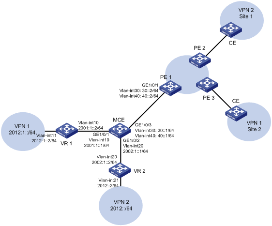
Configuration procedure
Assume that the system name of the MCE device is MCE, the system names of the edge devices of VPN 1 and VPN 2 are VR1 and VR2, and the system name of PE 1 is PE1.
1. Configure the VPN instances on the MCE and PE 1:
# On the MCE, configure VPN instances vpn1 and vpn2, and specify an RD and route targets for each VPN instance.
<MCE> system-view
[MCE] ip vpn-instance vpn1
[MCE-vpn-instance-vpn1] route-distinguisher 10:1
[MCE-vpn-instance-vpn1] vpn-target 10:1
[MCE-vpn-instance-vpn1] quit
[MCE] ip vpn-instance vpn2
[MCE-vpn-instance-vpn2] route-distinguisher 20:1
[MCE-vpn-instance-vpn2] vpn-target 20:1
[MCE-vpn-instance-vpn2] quit
# Create VLAN 10 and add GigabitEthernet 1/0/1 to the VLAN.
[MCE] vlan 10
[MCE-vlan10] port gigabitethernet 1/0/1
[MCE-vlan10] quit
# Bind VLAN-interface 10 to VPN instance vpn1, and configure an IPv6 address for the VLAN interface.
[MCE] interface vlan-interface 10
[MCE-Vlan-interface10] ip binding vpn-instance vpn1
[MCE-Vlan-interface10] ipv6 address 2001:1::1 64
[MCE-Vlan-interface10] quit
# Create VLAN 20 and add GigabitEthernet 1/0/2 to the VLAN.
[MCE] vlan 20
[MCE-vlan20] port gigabitethernet 1/0/2
[MCE-vlan20] quit
# Bind VLAN-interface 20 to VPN instance vpn2, and configure an IPv6 address for the VLAN interface.
[MCE] interface vlan-interface 20
[MCE-Vlan-interface20] ip binding vpn-instance vpn2
[MCE-Vlan-interface20] ipv6 address 2002:1::1 64
[MCE-Vlan-interface20] quit
# On PE 1, configure VPN instances vpn1 and vpn2, and specify an RD and route targets for each VPN instance.
<PE1> system-view
[PE1] ip vpn-instance vpn1
[PE1-vpn-instance-vpn1] route-distinguisher 30:1
[PE1-vpn-instance-vpn1] vpn-target 10:1
[PE1-vpn-instance-vpn1] quit
[PE1] ip vpn-instance vpn2
[PE1-vpn-instance-vpn2] route-distinguisher 40:1
[PE1-vpn-instance-vpn2] vpn-target 20:1
[PE1-vpn-instance-vpn2] quit
2. Configure routing between the MCE and VPN sites:
The MCE is connected to VPN 1 directly, and no routing protocol is enabled in VPN 1. Therefore, you can configure IPv6 static routes.
# On VR 1, assign IPv6 address 2001:1::2/64 to the interface connected to the MCE and 2012:1::2/64 to the interface connected to VPN 1. Add ports to VLANs. (Details not shown.)
# On VR 1, configure a default route with the next hop being 2001:1::1.
<VR1> system-view
[VR1] ipv6 route-static :: 0 2001:1::1
# On the MCE, configure an IPv6 static route to 2012:1::/64 with the next hop 2001:1::2. Bind the static route to VPN instance vpn1.
[MCE] ipv6 route-static vpn-instance vpn1 2012:1:: 64 2001:1::2
# Run RIPng in VPN 2. Configure RIPng process 20 for VPN instance vpn2 on the MCE, so that the MCE can learn the routes of VPN 2 and add them to the routing table of VPN instance vpn2.
[MCE] ripng 20 vpn-instance vpn2
# Advertise subnet 2002:1::/64 through RIPng.
[MCE] interface vlan-interface 20
[MCE-Vlan-interface20] ripng 20 enable
[MCE-Vlan-interface20] quit
# On VR 2, assign IPv6 address 2002:1::2/64 to the interface connected to the MCE and 2012::2/64 to the interface connected to VPN 2. (Details not shown.)
# Configure RIPng, and advertise subnets 2012::/64 and 2002:1::/64.
<VR2> system-view
[VR2] ripng 20
[VR2-ripng-20] quit
[VR2] interface vlan-interface 20
[VR2-Vlan-interface20] ripng 20 enable
[VR2-Vlan-interface20] quit
[VR2] interface vlan-interface 21
[VR2-Vlan-interface21] ripng 20 enable
[VR2-Vlan-interface21] quit
# On the MCE, display the routing tables of VPN instances vpn1 and vpn2.
[MCE] display ipv6 routing-table vpn-instance vpn1
Destinations : 6 Routes : 6
Destination: ::1/128 Protocol : Direct
NextHop : ::1 Preference: 0
Interface : InLoop0 Cost : 0
Destination: 2001:1::/64 Protocol : Direct
NextHop : :: Preference: 0
Interface : Vlan10 Cost : 0
Destination: 2001:1::1/128 Protocol : Direct
NextHop : ::1 Preference: 0
Interface : InLoop0 Cost : 0
Destination: 2012:1::/64 Protocol : Static
NextHop : 2001:1::2 Preference: 60
Interface : Vlan10 Cost : 0
Destination: FE80::/10 Protocol : Direct
NextHop : :: Preference: 0
Interface : NULL0 Cost : 0
Destination: FF00::/8 Protocol : Direct
NextHop : :: Preference: 0
Interface : NULL0 Cost : 0
[MCE] display ipv6 routing-table vpn-instance vpn2
Destinations : 6 Routes : 6
Destination: ::1/128 Protocol : Direct
NextHop : ::1 Preference: 0
Interface : InLoop0 Cost : 0
Destination: 2002:1::/64 Protocol : Direct
NextHop : :: Preference: 0
Interface : Vlan20 Cost : 0
Destination: 2002:1::1/128 Protocol : Direct
NextHop : ::1 Preference: 0
Interface : InLoop0 Cost : 0
Destination: 2012::/64 Protocol : RIPng
NextHop : FE80::20C:29FF:FE40:701 Preference: 100
Interface : Vlan20 Cost : 1
Destination: FE80::/10 Protocol : Direct
NextHop : :: Preference: 0
Interface : NULL0 Cost : 0
Destination: FF00::/8 Protocol : Direct
NextHop : :: Preference: 0
Interface : NULL0 Cost : 0
The output shows that the MCE has learned the private route of VPN 2. The MCE maintains the routes of VPN 1 and VPN 2 in two different routing tables. In this way, routes from different VPNs are separated.
3. Configure routing between the MCE and PE 1:
# The MCE uses GigabitEthernet 1/0/3 to connect to PE 1's port GigabitEthernet 1/0/1. Configure the two ports as trunk ports, and configure them to permit packets carrying VLAN tags 30 and 40 to pass.
[MCE] interface gigabitethernet 1/0/3
[MCE-GigabitEthernet1/0/3] port link-type trunk
[MCE-GigabitEthernet1/0/3] port trunk permit vlan 30 40
[MCE-GigabitEthernet1/0/3] quit
# Configure GigabitEthernet 1/0/1 on PE 1.
[PE1] interface gigabitethernet 1/0/1
[PE1-GigabitEthernet1/0/1] port link-type trunk
[PE1-GigabitEthernet1/0/1] port trunk permit vlan 30 40
[PE1-GigabitEthernet1/0/1] quit
# On the MCE, create VLAN-interface 30, bind the VLAN interface to VPN instance vpn1, and configure an IPv6 address for the VLAN interface.
[MCE] vlan 30
[MCE-vlan30] quit
[MCE] interface vlan-interface 30
[MCE-Vlan-interface30] ip binding vpn-instance vpn1
[MCE-Vlan-interface30] ipv6 address 30::1 64
[MCE-Vlan-interface30] quit
# Create VLAN-interface 40, bind the VLAN interface to VPN instance vpn2, and configure an IPv6 address for the VLAN interface.
[MCE] vlan 40
[MCE-vlan40] quit
[MCE] interface vlan-interface 40
[MCE-Vlan-interface40] ip binding vpn-instance vpn2
[MCE-Vlan-interface40] ipv6 address 40::1 64
[MCE-Vlan-interface40] quit
# On PE 1, create VLAN-interface 30, bind the VLAN interface to VPN instance vpn1, and configure an IPv6 address for the VLAN interface.
[PE1] vlan 30
[PE1-vlan30] quit
[PE1] interface vlan-interface 30
[PE1-Vlan-interface30] ip binding vpn-instance vpn1
[PE1-Vlan-interface30] ipv6 address 30::2 64
[PE1-Vlan-interface30] quit
# Create VLAN-interface 40, bind the VLAN interface to VPN instance vpn2, and configure an IPv6 address for the VLAN interface.
[PE1] vlan 40
[PE1-vlan40] quit
[PE1] interface vlan-interface 40
[PE1-Vlan-interface40] ip binding vpn-instance vpn2
[PE1-Vlan-interface40] ipv6 address 40::2 64
[PE1-Vlan-interface40] quit
# Configure the IP address of the interface Loopback 0 as 101.101.10.1 for the MCE and as 100.100.10.1 for PE 1. Specify the loopback interface address as the router ID for the MCE and PE 1. (Details not shown.)
# Enable OSPFv3 process 10 on the MCE, and bind the process to VPN instance vpn1.
[MCE] ospfv3 10 vpn-instance vpn1
# Redistribute the IPv6 static route of VPN 1.
[MCE-ospf-10] router-id 101.101.10.1
[MCE-ospf-10] import-route static
[MCE-ospf-10] quit
# Enable OSPFv3 on VLAN-interface 30.
[MCE] interface vlan-interface 30
[MCE-Vlan-interface30] ospfv3 10 area 0.0.0.0
[MCE-Vlan-interface30] quit
# On PE 1, enable OSPFv3 process 10 and bind the process to VPN instance vpn1.
[PE1] ospfv3 10 vpn-instance vpn1
[PE1-ospf-10] router-id 100.100.10.1
[PE1-ospf-10] quit
# Enable OSPFv3 on VLAN-interface 30.
[PE1] interface vlan-interface 30
[PE1-Vlan-interface30] ospfv3 10 area 0.0.0.0
[PE1-Vlan-interface30] quit
# Configure OSPFv3 process 20 between the MCE and PE 1. (Details not shown.)
# Redistribute VPN 2's routes from RIPng process 20 into the OSPFv3 routing table of the MCE. (Details not shown.)
Verifying the configuration
# Verify that PE 1 has learned the private route of VPN 1 through OSPFv3.
[PE1] display ipv6 routing-table vpn-instance vpn1
Destinations : 6 Routes : 6
Destination: ::1/128 Protocol : Direct
NextHop : ::1 Preference: 0
Interface : InLoop0 Cost : 0
Destination: 30::/64 Protocol : Direct
NextHop : :: Preference: 0
Interface : Vlan30 Cost : 0
Destination: 30::2/128 Protocol : Direct
NextHop : ::1 Preference: 0
Interface : InLoop0 Cost : 0
Destination: 2012:1::/64 Protocol : O_ASE2
NextHop : FE80::202:FF:FE02:2 Preference: 150
Interface : Vlan30 Cost : 1
Destination: FE80::/10 Protocol : Direct
NextHop : :: Preference: 0
Interface : NULL0 Cost : 0
Destination: FF00::/8 Protocol : Direct
NextHop : :: Preference: 0
Interface : NULL0 Cost : 0
# Verify that PE 1 has learned the private route of VPN 2 through OSPFv3.
[PE1] display ipv6 routing-table vpn-instance vpn2
Destinations : 6 Routes : 6
Destination: ::1/128 Protocol : Direct
NextHop : ::1 Preference: 0
Interface : InLoop0 Cost : 0
Destination: 40::/64 Protocol : Direct
NextHop : :: Preference: 0
Interface : Vlan40 Cost : 0
Destination: 40::2/128 Protocol : Direct
NextHop : ::1 Preference: 0
Interface : InLoop0 Cost : 0
Destination: 2012::/64 Protocol : O_ASE2
NextHop : FE80::200:FF:FE0F:5 Preference: 150
Interface : Vlan40 Cost : 1
Destination: FE80::/10 Protocol : Direct
NextHop : :: Preference: 0
Interface : NULL0 Cost : 0
Destination: FF00::/8 Protocol : Direct
NextHop : :: Preference: 0
Interface : NULL0 Cost : 0
The routing information for the two VPNs has been added into the routing tables on PE 1.
