- Table of Contents
- Related Documents
-
| Title | Size | Download |
|---|---|---|
| 05-Static CRLSP configuration | 78.09 KB |
Configuring a static CRLSP
Overview
A static Constraint-based Routed Label Switched Path (CRLSP) is established by manually specifying CRLSP setup information on the ingress, transit, and egress nodes of the forwarding path. The CRLSP setup information includes incoming label, outgoing label, and required bandwidth. If the device does not have enough bandwidth resources required by a CRLSP, the CRLSP cannot be established.
Static CRLSPs consume fewer resources, but they cannot automatically adapt to network topology changes. Therefore, static CRLSPs are suitable for small and stable networks with simple topologies.
Follow these guidelines to establish a static CRLSP:
· Configure the ingress node as follows:
¡ Specify the outgoing label for the CRLSP, the next hop or the outgoing interface to the next hop, and the required bandwidth.
¡ Create an MPLS TE tunnel interface.
¡ Reference the static CRLSP for the tunnel interface.
The tunnel interface adds the outgoing label of the static CRLSP to each packet, and forwards the packet to the next hop or out of the outgoing interface.
· A transit node swaps the label carried in a received packet with a specific label. It forwards the packet to the next hop or out of the outgoing interface. You must specify the incoming label, the outgoing label, the next hop or the outgoing interface, and the required bandwidth on each transit node.
· If it is not configured with the penultimate hop popping function, an egress node pops the incoming label of a packet. It performs label forwarding according to the inner label or IP forwarding. You are only required to specify the incoming label on the egress node.
· The outgoing label specified on an LSR must be the same as the incoming label specified on the directly connected downstream LSR.
Configuration procedure
Static CRLSPs are special static LSPs. They use the same label space as static LSPs. On a device, a static CRLSP and a static LSP cannot use the same incoming label.
A static CRLSP can be used to forward MPLS TE traffic only after you create an MPLS TE tunnel interface on the ingress node and reference the static CRLSP for the tunnel interface. For more information about MPLS TE, see "Configuring MPLS TE."
Before you configure a static CRLSP, perform the following tasks:
· Identify the ingress node, transit nodes, and egress node of the CRLSP.
· Enable MPLS on all interfaces that participate in MPLS forwarding. For more information, see "Configuring basic MPLS."
· Enable MPLS TE for each node and interface that the CRLSP traverses. For more information, see "Configuring MPLS TE."
To configure a static CRLSP:
|
Step |
Command |
Remarks |
|
1. Enter system view. |
system-view |
N/A |
|
2. Create a static CRLSP. |
·
Configure the ingress node: ·
Configure a transit node: ·
Configure the egress node: |
Use one command according to the position of a device on the network. By default, no static CRLSP exists. Do not configure the next hop address as a local public IP address when configuring the static CRLSP on the ingress node or a transit node. You do not need to execute the static-cr-lsp egress command on the egress node if the outgoing label configured on the penultimate hop of the static CRLSP is 0 or 3. |
Displaying static CRLSPs
Execute display commands in any view.
|
Task |
Command |
|
Display static CRLSP information. |
display mpls static-cr-lsp [ lsp-name lsp-name ] [ verbose ] |
Static CRLSP configuration example
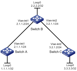
Network requirements
Switch A, Switch B, and Switch C run IS-IS.
Establish an MPLS TE tunnel over a static CRLSP from Switch A to Switch C.
Figure 1 Network diagram
Configuration procedure
1. Configure IP addresses and masks for interfaces. (Details not shown.)
2. Configure IS-IS to advertise interface addresses, including the loopback interface address:
# Configure Switch A.
<SwitchA> system-view
[SwitchA] isis 1
[SwitchA-isis-1] network-entity 00.0005.0000.0000.0001.00
[SwitchA-isis-1] quit
[SwitchA] interface vlan-interface 1
[SwitchA-Vlan-interface1] isis enable 1
[SwitchA-Vlan-interface1] quit
[SwitchA] interface loopback 0
[SwitchA-LoopBack0] isis enable 1
[SwitchA-LoopBack0] quit
# Configure Switch B.
<SwitchB> system-view
[SwitchB] isis 1
[SwitchB-isis-1] network-entity 00.0005.0000.0000.0002.00
[SwitchB-isis-1] quit
[SwitchB] interface vlan-interface 1
[SwitchB-Vlan-interface1] isis enable 1
[SwitchB-Vlan-interface1] quit
[SwitchB] interface vlan-interface 2
[SwitchB-Vlan-interface2] isis enable 1
[SwitchB-Vlan-interface2] quit
[SwitchB] interface loopback 0
[SwitchB-LoopBack0] isis enable 1
[SwitchB-LoopBack0] quit
# Configure Switch C.
<SwitchC> system-view
[SwitchC] isis 1
[SwitchC-isis-1] network-entity 00.0005.0000.0000.0003.00
[SwitchC-isis-1] quit
[SwitchC] interface vlan-interface 2
[SwitchC-Vlan-interface2] isis enable 1
[SwitchC-Vlan-interface2] quit
[SwitchC] interface loopback 0
[SwitchC-LoopBack0] isis enable 1
[SwitchC-LoopBack0] quit
# Execute the display ip routing-table command on each switch to verify that the switches have learned the routes to one another, including the routes to the Loopback interfaces. (Details not shown.)
3. Configure an LSR ID, and enable MPLS and MPLS TE:
# Configure Switch A.
[SwitchA] mpls lsr-id 1.1.1.1
[SwitchA] mpls te
[SwitchA-te] quit
[SwitchA] interface vlan-interface 1
[SwitchA-Vlan-interface1] mpls enable
[SwitchA-Vlan-interface1] mpls te enable
[SwitchA-Vlan-interface1] quit
# Configure Switch B.
[SwitchB] mpls lsr-id 2.2.2.2
[SwitchB] mpls te
[SwitchB-te] quit
[SwitchB] interface vlan-interface 1
[SwitchB-Vlan-interface1] mpls enable
[SwitchB-Vlan-interface1] mpls te enable
[SwitchB-Vlan-interface1] quit
[SwitchB] interface vlan-interface 2
[SwitchB-Vlan-interface2] mpls enable
[SwitchB-Vlan-interface2] mpls te enable
[SwitchB-Vlan-interface2] quit
# Configure Switch C.
[SwitchC] mpls lsr-id 3.3.3.3
[SwitchC] mpls te
[SwitchC-te] quit
[SwitchC] interface vlan-interface 2
[SwitchC-Vlan-interface2] mpls enable
[SwitchC-Vlan-interface2] mpls te enable
[SwitchC-Vlan-interface2] quit
4. Configure an MPLS TE tunnel on Switch A:
# Configure MPLS TE tunnel interface Tunnel 0.
[SwitchA] interface tunnel 0 mode mpls-te
[SwitchA-Tunnel0] ip address 6.1.1.1 255.255.255.0
# Specify the tunnel destination address as the LSR ID of Switch C.
[SwitchA-Tunnel0] destination 3.3.3.3
# Configure MPLS TE to use a static CRLSP to establish the tunnel.
[SwitchA-Tunnel0] mpls te signaling static
[SwitchA-Tunnel0] quit
5. Create a static CRLSP:
# Configure Switch A as the ingress node of the static CRLSP, and specify the next hop address as 2.1.1.2 and outgoing label as 20.
[SwitchA] static-cr-lsp ingress static-cr-lsp-1 nexthop 2.1.1.2 out-label 20
# On Switch A, configure tunnel 0 to reference the static CRLSP static-cr-lsp-1.
[SwitchA] interface Tunnel0
[SwitchA-Tunnel0] mpls te static-cr-lsp static-cr-lsp-1
[SwitchA-Tunnel0] quit
# Configure Switch B as the transit node of the static CRLSP, and specify the incoming label as 20, the next hop address as 3.2.1.2, and outgoing label as 30.
[SwitchB] static-cr-lsp transit static-cr-lsp-1 in-label 20 nexthop 3.2.1.2 out-label 30
# Configure Switch C as the egress node of the static CRLSP, and specify the incoming label as 30.
[SwitchC] static-cr-lsp egress static-cr-lsp-1 in-label 30
6. Configure a static route on Switch A to direct traffic destined for subnet 3.2.1.0/24 to MPLS TE tunnel 0.
[SwitchA] ip route-static 3.2.1.2 24 tunnel 0 preference 1
Verifying the configuration
# Execute the display interface tunnel command on Switch A. The output shows that the tunnel interface is up.
[SwitchA] display interface tunnel
Tunnel0
Current state: UP
Line protocol state: UP
Description: Tunnel0 Interface
Bandwidth: 64kbps
Maximum Transmit Unit: 64000
Internet Address is 6.1.1.1/24 Primary
Tunnel source unknown, destination 3.3.3.3
Tunnel TTL 255
Tunnel protocol/transport CR_LSP
Last clearing of counters: Never
Last 300 seconds input rate: 0 bytes/sec, 0 bits/sec, 0 packets/sec
Last 300 seconds output rate: 0 bytes/sec, 0 bits/sec, 0 packets/sec
Input: 0 packets, 0 bytes, 0 drops
Output: 0 packets, 0 bytes, 0 drops
# Execute the display mpls te tunnel-interface command on Switch A to display detailed information about the MPLS TE tunnel.
[SwitchA] display mpls te tunnel-interface
Tunnel Name : Tunnel 0
Tunnel State : Up (Main CRLSP up)
Tunnel Attributes :
LSP ID : 1 Tunnel ID : 0
Admin State : Normal
Ingress LSR ID : 1.1.1.1 Egress LSR ID : 3.3.3.3
Signaling : Static Static CRLSP Name : static-cr-lsp-1
Resv Style : -
Tunnel mode : -
Reverse-LSP name : -
Reverse-LSP LSR ID : - Reverse-LSP Tunnel ID: -
Class Type : - Tunnel Bandwidth : -
Reserved Bandwidth : -
Setup Priority : 0 Holding Priority : 0
Affinity Attr/Mask : -/-
Explicit Path : -
Backup Explicit Path : -
Metric Type : TE
Record Route : - Record Label : -
FRR Flag : - Backup Bandwidth Flag: -
Backup Bandwidth Type: - Backup Bandwidth : -
Route Pinning : -
Retry Limit : 10 Retry Interval : 2 sec
Reoptimization : - Reoptimization Freq : -
Backup Type : - Backup LSP ID : -
Auto Bandwidth : - Auto Bandwidth Freq : -
Min Bandwidth : - Max Bandwidth : -
Collected Bandwidth : -
# Execute the display mpls lsp command or the display mpls static-cr-lsp command on each switch to display the static CRLSP information.
[SwitchA] display mpls lsp
FEC Proto In/Out Label Interface/Out NHLFE
1.1.1.1/0/1 StaticCR -/20 Vlan1
2.1.1.2 Local -/- Vlan1
[SwitchB] display mpls lsp
FEC Proto In/Out Label Interface/Out NHLFE
- StaticCR 20/30 Vlan2
3.2.1.2 Local -/- Vlan2
[SwitchC] display mpls lsp
FEC Proto In/Out Label Interface/Out NHLFE
- StaticCR 30/- -
[SwitchA] display mpls static-cr-lsp
Name LSR Type In/Out Label Out Interface State
static-cr-lsp-1 Ingress Null/20 Vlan1 Up
[SwitchB] display mpls static-cr-lsp
Name LSR Type In/Out Label Out Interface State
static-cr-lsp-1 Transit 20/30 Vlan2 Up
[SwitchC] display mpls static-cr-lsp
Name LSR Type In/Out Label Out Interface State
static-cr-lsp1 Egress 30/Null - Up
# Execute the display ip routing-table command on Switch A. The output shows a static route entry with interface Tunnel 0 as the egress interface. (Details not shown.)