- Table of Contents
- Related Documents
-
| Title | Size | Download |
|---|---|---|
| 01-Text | 2.48 MB |
AAA implementation on the device
AAA configuration considerations and task list
Configuring AAA methods for ISP domains
Configuring authentication methods for an ISP domain
Configuring authorization methods for an ISP domain
Configuring accounting methods for an ISP domain
Enabling the session-control feature
Setting the maximum number of concurrent login users
Displaying and maintaining AAA
AAA for SSH users by an HWTACACS server
Local authentication, HWTACACS authorization, and RADIUS accounting for SSH users
Authentication and authorization for SSH users by a RADIUS server
RADIUS packet delivery failure
Password updating and expiration
Password not displayed in any form
Password control configuration task list
Setting global password control parameters
Setting user group password control parameters
Setting local user password control parameters
Setting super password control parameters
Displaying and maintaining password control
Password control configuration example
Distributing a local host public key
Exporting a host public key in a specific format to a file
Displaying a host public key in a specific format and saving it to a file
Importing a peer host public key from a public key file
Displaying and maintaining public keys
Examples of public key management
Example for entering a peer public key
Example for importing a public key from a public key file
Feature and software version compatibility
Configuring automatic certificate request
Manually requesting a certificate
Aborting a certificate request
Verifying certificates with CRL checking
Verifying certificates without CRL checking·
Specifying the storage path for the certificates and CRLs
Configuring a certificate-based access control policy
Displaying and maintaining PKI
Requesting a certificate from an RSA Keon CA server
Requesting a certificate from a Windows Server 2003 CA server
Requesting a certificate from an OpenCA server
Certificate import and export configuration example
Troubleshooting PKI configuration
Failed to obtain the CA certificate
Failed to obtain local certificates
Failed to request local certificates
Failed to import the CA certificate
Failed to import a local certificate
Failed to set the storage path
Feature and software version compatibility
Configuring an SSL server policy
Configuring an SSL client policy
Displaying and maintaining SSL
Security protocols and encapsulation modes
Feature restrictions and guidelines
ACL-based IPsec configuration task list
Configuring an IPsec transform set
Configuring a manual IPsec policy
Configuring an IKE-based IPsec policy
Applying an IPsec policy to an interface
Enabling ACL checking for de-encapsulated packets
Binding a source interface to an IPsec policy
Enabling logging of IPsec packets
Configuring the DF bit of IPsec packets·
Configuring SNMP notifications for IPsec
Displaying and maintaining IPsec
Configuring a manual mode IPsec tunnel for IPv4 packets
Configuring an IKE-based IPsec tunnel for IPv4 packets
IKE configuration prerequisites
Configuring the global identity information
Configuring the IKE keepalive feature
Configuring the IKE NAT keepalive feature
Setting the maximum number of IKE SAs
Configuring SNMP notifications for IKE
Displaying and maintaining IKE
Main mode IKE with pre-shared key authentication configuration example
IKE negotiation failed because no matching IKE proposals were found
IKE negotiation failed because no IKE proposals or IKE keychains are referenced correctly
IPsec SA negotiation failed because no matching IPsec transform sets were found
IPsec SA negotiation failed due to invalid identity information
Configuring the device as an SSH server
SSH server configuration task list
Generating local DSA or RSA key pairs
Configuring user lines for SSH login·
Configuring a client's host public key
Setting the SSH management parameters
Configuring the device as an Stelnet client
Stelnet client configuration task list
Specifying a source IP address for SSH packets
Establishing a connection to an Stelnet server
Configuring the device as an SFTP client
SFTP client configuration task list
Specifying the source IP address for SFTP packets
Establishing a connection to an SFTP server
Terminating the connection with the SFTP server
Configuring the device as an SCP client
Displaying and maintaining SSH
Stelnet configuration examples
Password authentication enabled Stelnet server configuration example
Publickey authentication enabled Stelnet server configuration example
Password authentication enabled Stelnet client configuration example
Publickey authentication enabled Stelnet client configuration example
Password authentication enabled SFTP server configuration example
Publickey authentication enabled SFTP client configuration example
SCP file transfer with password authentication
Configuring the IPv4SG feature
Enabling IPv4SG on an interface
Configuring a static IPv4SG binding
Displaying and maintaining IPSG
Static IPv4SG configuration example
Dynamic IPv4SG using DHCP snooping configuration example
Dynamic IPv4SG using DHCP relay configuration example
Configuring ARP attack protection
ARP attack protection configuration task list
Configuring unresolvable IP attack protection·
Configuring ARP source suppression
Configuring ARP blackhole routing
Displaying and maintaining unresolvable IP attack protection
Configuring ARP packet rate limit
Configuring source MAC-based ARP attack detection
Displaying and maintaining source MAC-based ARP attack detection
Configuring ARP packet source MAC consistency check
Configuring ARP active acknowledgement
Configuring user validity check
Configuring ARP packet validity check
Configuring ARP restricted forwarding
Enabling ARP detection logging
Displaying and maintaining ARP detection
User validity check and ARP packet validity check configuration example
Configuring ARP scanning and fixed ARP
Configuration restrictions and guidelines
Configuring ARP gateway protection
Displaying and maintaining uRPF
Configuration restrictions and guidelines
Configuration changes in FIPS mode
Displaying and maintaining FIPS
Entering FIPS mode through automatic reboot
Entering FIPS mode through manual reboot
Exiting FIPS mode through automatic reboot
Exiting FIPS mode through manual reboot
Configuring attack detection and prevention
Enabling TCP fragment attack prevention
Configuring AAA
Overview
Authentication, Authorization, and Accounting (AAA) provides a uniform framework for implementing network access management. This feature specifies the following security functions:
· Authentication—Identifies users and verifies their validity.
· Authorization—Grants different users different rights, and controls the users' access to resources and services. For example, you can permit office users to read and print files and prevent guests from accessing files on the device.
· Accounting—Records network usage details of users, including the service type, start time, and traffic. This function enables time-based and traffic-based charging and user behavior auditing.
AAA uses a client/server model. The client runs on the access device, or the network access server (NAS), which authenticates user identities and controls user access. The server maintains user information centrally. See Figure 1.
Figure 1 AAA network diagram
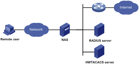
To access networks or resources beyond the NAS, a user sends its identity information to the NAS. The NAS transparently passes the user information to AAA servers and waits for the authentication, authorization, and accounting result. Based on the result, the NAS determines whether to permit or deny the access request.
AAA has various implementations, including RADIUS and HWTACACS. RADIUS is most often used.
The network in Figure 1 has one RADIUS server and one HWTACACS server. You can use different servers to implement different security functions. For example, you can use the HWTACACS server for authentication and authorization, and use the RADIUS server for accounting.
You can choose the security functions provided by AAA as needed. For example, if your company wants employees to be authenticated before they access specific resources, you would deploy an authentication server. If network usage information is needed, you would also configure an accounting server.
The device performs dynamic password authentication.
RADIUS
Remote Authentication Dial-In User Service (RADIUS) is a distributed information interaction protocol that uses a client/server model. The protocol can protect networks against unauthorized access and is often used in network environments that require both high security and remote user access.
The RADIUS authorization process is combined with the RADIUS authentication process, and user authorization information is piggybacked in authentication responses. RADIUS uses UDP port 1812 for authentication and UDP port 1813 for accounting.
RADIUS was originally designed for dial-in user access, and has been extended to support additional access methods, such as Ethernet and ADSL.
Client/server model
The RADIUS client runs on the NASs located throughout the network. It passes user information to RADIUS servers and acts on the responses to, for example, reject or accept user access requests.
The RADIUS server runs on the computer or workstation at the network center and maintains information related to user authentication and network service access.
The RADIUS server operates using the following process:
1. Receives authentication, authorization, and accounting requests from RADIUS clients.
2. Performs user authentication, authorization, or accounting.
3. Returns user access control information (for example, rejecting or accepting the user access request) to the clients.
The RADIUS server can also act as the client of another RADIUS server to provide authentication proxy services.
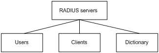
The RADIUS server maintains the following databases:
· Users—Stores user information, such as the usernames, passwords, applied protocols, and IP addresses.
· Clients—Stores information about RADIUS clients, such as shared keys and IP addresses.
· Dictionary—Stores RADIUS protocol attributes and their values.
Figure 2 RADIUS server databases
Information exchange security mechanism
The RADIUS client and server exchange information between them with the help of shared keys, which are preconfigured on the client and server. A RADIUS packet has a 16-byte field called Authenticator. This field includes a signature generated by using the MD5 algorithm, the shared key, and some other information. The receiver of the packet verifies the signature and accepts the packet only when the signature is correct. This mechanism ensures the security of information exchanged between the RADIUS client and server.
The shared keys are also used to encrypt user passwords that are included in RADIUS packets.
User authentication methods
The RADIUS server supports multiple user authentication methods, such as PAP, CHAP, and EAP.
Basic RADIUS packet exchange process
Figure 3 illustrates the interactions between a user host, the RADIUS client, and the RADIUS server.
Figure 3 Basic RADIUS packet exchange process
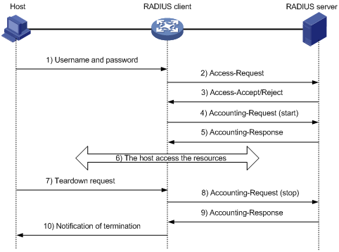
RADIUS uses the following workflow:
1. The host sends a connection request that includes the user's username and password to the RADIUS client.
2. The RADIUS client sends an authentication request (Access-Request) to the RADIUS server. The request includes the user's password, which has been processed by the MD5 algorithm and shared key.
3. The RADIUS server authenticates the username and password. If the authentication succeeds, the server sends back an Access-Accept packet that contains the user's authorization information. If the authentication fails, the server returns an Access-Reject packet.
4. The RADIUS client permits or denies the user according to the authentication result. If the result permits the user, the RADIUS client sends a start-accounting request (Accounting-Request) packet to the RADIUS server.
5. The RADIUS server returns an acknowledgment (Accounting-Response) packet and starts accounting.
6. The user accesses the network resources.
7. The host requests the RADIUS client to tear down the connection.
8. The RADIUS client sends a stop-accounting request (Accounting-Request) packet to the RADIUS server.
9. The RADIUS server returns an acknowledgment (Accounting-Response) and stops accounting for the user.
10. The RADIUS client notifies the user of the termination.
RADIUS packet format
RADIUS uses UDP to transmit packets. The protocol also uses a series of mechanisms to ensure smooth packet exchange between the RADIUS server and the client. These mechanisms include the timer mechanism, the retransmission mechanism, and the backup server mechanism.
Figure 4 RADIUS packet format
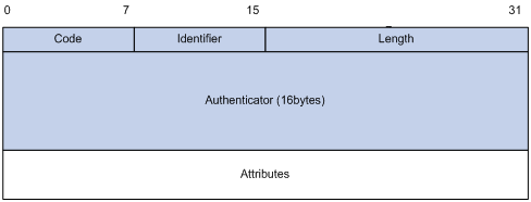
Descriptions of the fields are as follows:
· The Code field (1 byte long) indicates the type of the RADIUS packet. Table 1 gives the main values and their meanings.
Table 1 Main values of the Code field
|
Code |
Packet type |
Description |
|
1 |
Access-Request |
From the client to the server. A packet of this type includes user information for the server to authenticate the user. It must contain the User-Name attribute and can optionally contain the attributes of NAS-IP-Address, User-Password, and NAS-Port. |
|
2 |
Access-Accept |
From the server to the client. If all attribute values included in the Access-Request are acceptable, the authentication succeeds, and the server sends an Access-Accept response. |
|
3 |
Access-Reject |
From the server to the client. If any attribute value included in the Access-Request is unacceptable, the authentication fails, and the server sends an Access-Reject response. |
|
4 |
Accounting-Request |
From the client to the server. A packet of this type includes user information for the server to start or stop accounting for the user. The Acct-Status-Type attribute in the packet indicates whether to start or stop accounting. |
|
5 |
Accounting-Response |
From the server to the client. The server sends a packet of this type to notify the client that it has received the Accounting-Request and has successfully recorded the accounting information. |
· The Identifier field (1 byte long) is used to match response packets with request packets and to detect duplicate request packets. The request and response packets of the same exchange process for the same purpose (such as authentication or accounting) have the same identifier.
· The Length field (2 bytes long) indicates the length of the entire packet (in bytes), including the Code, Identifier, Length, Authenticator, and Attributes fields. Bytes beyond this length are considered padding and are ignored by the receiver. If the length of a received packet is less than this length, the packet is dropped.
· The Authenticator field (16 bytes long) is used to authenticate responses from the RADIUS server and to encrypt user passwords. There are two types of authenticators: request authenticator and response authenticator.
· The Attributes field (variable in length) includes authentication, authorization, and accounting information. This field can contain multiple attributes, each with the following subfields:
? Type—Type of the attribute.
? Length—Length of the attribute in bytes, including the Type, Length, and Value subfields.
? Value—Value of the attribute. Its format and content depend on the Type subfield.
Commonly used RADIUS attributes are defined in RFC 2865, RFC 2866, RFC 2867, and RFC 2868. For more information, see "Commonly used standard RADIUS attributes."
Table 2 Commonly used RADIUS attributes
|
No. |
Attribute |
No. |
Attribute |
|
1 |
User-Name |
45 |
Acct-Authentic |
|
2 |
User-Password |
46 |
Acct-Session-Time |
|
3 |
CHAP-Password |
47 |
Acct-Input-Packets |
|
4 |
NAS-IP-Address |
48 |
Acct-Output-Packets |
|
5 |
NAS-Port |
49 |
Acct-Terminate-Cause |
|
6 |
Service-Type |
50 |
Acct-Multi-Session-Id |
|
7 |
Framed-Protocol |
51 |
Acct-Link-Count |
|
8 |
Framed-IP-Address |
52 |
Acct-Input-Gigawords |
|
9 |
Framed-IP-Netmask |
53 |
Acct-Output-Gigawords |
|
10 |
Framed-Routing |
54 |
(unassigned) |
|
11 |
Filter-ID |
55 |
Event-Timestamp |
|
12 |
Framed-MTU |
56-59 |
(unassigned) |
|
13 |
Framed-Compression |
60 |
CHAP-Challenge |
|
14 |
Login-IP-Host |
61 |
NAS-Port-Type |
|
15 |
Login-Service |
62 |
Port-Limit |
|
16 |
Login-TCP-Port |
63 |
Login-LAT-Port |
|
17 |
(unassigned) |
64 |
Tunnel-Type |
|
18 |
Reply-Message |
65 |
Tunnel-Medium-Type |
|
19 |
Callback-Number |
66 |
Tunnel-Client-Endpoint |
|
20 |
Callback-ID |
67 |
Tunnel-Server-Endpoint |
|
21 |
(unassigned) |
68 |
Acct-Tunnel-Connection |
|
22 |
Framed-Route |
69 |
Tunnel-Password |
|
23 |
Framed-IPX-Network |
70 |
ARAP-Password |
|
24 |
State |
71 |
ARAP-Features |
|
25 |
Class |
72 |
ARAP-Zone-Access |
|
26 |
Vendor-Specific |
73 |
ARAP-Security |
|
27 |
Session-Timeout |
74 |
ARAP-Security-Data |
|
28 |
Idle-Timeout |
75 |
Password-Retry |
|
29 |
Termination-Action |
76 |
Prompt |
|
30 |
Called-Station-Id |
77 |
Connect-Info |
|
31 |
Calling-Station-Id |
78 |
Configuration-Token |
|
32 |
NAS-Identifier |
79 |
EAP-Message |
|
33 |
Proxy-State |
80 |
Message-Authenticator |
|
34 |
Login-LAT-Service |
81 |
Tunnel-Private-Group-id |
|
35 |
Login-LAT-Node |
82 |
Tunnel-Assignment-id |
|
36 |
Login-LAT-Group |
83 |
Tunnel-Preference |
|
37 |
Framed-AppleTalk-Link |
84 |
ARAP-Challenge-Response |
|
38 |
Framed-AppleTalk-Network |
85 |
Acct-Interim-Interval |
|
39 |
Framed-AppleTalk-Zone |
86 |
Acct-Tunnel-Packets-Lost |
|
40 |
Acct-Status-Type |
87 |
NAS-Port-Id |
|
41 |
Acct-Delay-Time |
88 |
Framed-Pool |
|
42 |
Acct-Input-Octets |
89 |
(unassigned) |
|
43 |
Acct-Output-Octets |
90 |
Tunnel-Client-Auth-id |
|
44 |
Acct-Session-Id |
91 |
Tunnel-Server-Auth-id |
Extended RADIUS attributes
The RADIUS protocol features excellent extensibility. The Vendor-Specific attribute (attribute 26) allows a vendor to define extended attributes. The extended attributes implement functions that the standard RADIUS protocol does not provide.
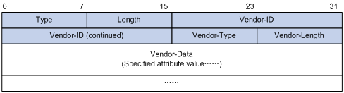
A vendor can encapsulate multiple subattributes in the TLV format in attribute 26 to provide extended functions. As shown in Figure 5, a subattribute encapsulated in attribute 26 consists of the following parts:
· Vendor-ID—ID of the vendor. The most significant byte is 0. The other three bytes contains a code compliant to RFC 1700.
· Vendor-Type—Type of the subattribute.
· Vendor-Length—Length of the subattribute.
· Vendor-Data—Contents of the subattribute.
For more information about the proprietary RADIUS subattributes of H3C, see "H3C proprietary RADIUS subattributes."
Figure 5 Format of attribute 26
HWTACACS
HWTACACS typically provides AAA services for PPP, VPDN, and terminal users. In a typical HWTACACS scenario, terminal users need to log in to the NAS. Working as the HWTACACS client, the NAS sends users' usernames and passwords to the HWTACACS server for authentication. After passing authentication and obtaining authorized rights, a user logs in to the device and performs operations. The HWTACACS server records the operations that each user performs.
Differences between HWTACACS and RADIUS
HWTACACS and RADIUS have many features in common, such as using a client/server model, using shared keys for data encryption, and providing flexibility and scalability. Table 3 lists the primary differences between HWTACACS and RADIUS.
Table 3 Primary differences between HWTACACS and RADIUS
|
HWTACACS |
RADIUS |
|
Uses TCP, which provides reliable network transmission. |
Uses UDP, which provides high transport efficiency. |
|
Encrypts the entire packet except for the HWTACACS header. |
Encrypts only the user password field in an authentication packet. |
|
Protocol packets are complicated and authorization is independent of authentication. Authentication and authorization can be deployed on different HWTACACS servers. |
Protocol packets are simple and the authorization process is combined with the authentication process. |
|
Supports authorization of configuration commands. Access to commands depends on both the user's roles and authorization. A user can use only commands that are permitted by the user roles and authorized by the HWTACACS server. |
Does not support authorization of configuration commands. Access to commands solely depends on the user's roles. For more information about user roles, see Fundamentals Configuration Guide. |
Basic HWTACACS packet exchange process
Figure 6 describes how HWTACACS performs user authentication, authorization, and accounting for a Telnet user.
Figure 6 Basic HWTACACS packet exchange process for a Telnet user
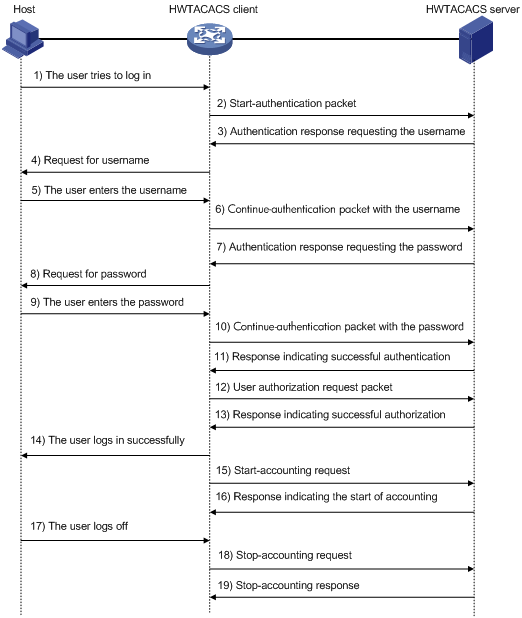
HWTACACS operates using the following workflow:
1. A Telnet user sends an access request to the HWTACACS client.
2. The HWTACACS client sends a start-authentication packet to the HWTACACS server when it receives the request.
3. The HWTACACS server sends back an authentication response to request the username.
4. Upon receiving the response, the HWTACACS client asks the user for the username.
5. The user enters the username.
6. After receiving the username from the user, the HWTACACS client sends the server a continue-authentication packet that includes the username.
7. The HWTACACS server sends back an authentication response to request the login password.
8. Upon receipt of the response, the HWTACACS client prompts the user for the login password.
9. The user enters the password.
10. After receiving the login password, the HWTACACS client sends the HWTACACS server a continue-authentication packet that includes the login password.
11. If the authentication succeeds, the HWTACACS server sends back an authentication response to indicate that the user has passed authentication.
12. The HWTACACS client sends a user authorization request packet to the HWTACACS server.
13. If the authorization succeeds, the HWTACACS server sends back an authorization response, indicating that the user is now authorized.
14. Knowing that the user is now authorized, the HWTACACS client pushes its CLI to the user and permits the user to log in.
15. The HWTACACS client sends a start-accounting request to the HWTACACS server.
16. The HWTACACS server sends back an accounting response, indicating that it has received the start-accounting request.
17. The user logs off.
18. The HWTACACS client sends a stop-accounting request to the HWTACACS server.
19. The HWTACACS server sends back a stop-accounting response, indicating that the stop-accounting request has been received.
AAA implementation on the device
This section describes AAA user management and methods.
User management based on ISP domains and user access types
AAA manages users based on the users' ISP domains and access types.
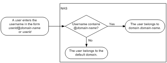
On a NAS, each user belongs to one ISP domain. The NAS determines the ISP domain to which a user belongs based on the username entered by the user at login.
Figure 7 Determining the ISP domain for a user by username
AAA manages users in the same ISP domain based on the users' access types. The device supports AAA for login users. Login users include SSH, Telnet, FTP, and terminal users who log in to the device. Terminal users can access through a console port.
AAA methods
AAA supports configuring different authentication, authorization, and accounting methods for different types of users in an ISP domain. The NAS determines the ISP domain and access type of a user, and uses the methods configured for the access type in the domain to control the user's access.
AAA also supports configuring a set of default methods for an ISP domain. These default methods are applied to users for whom no AAA methods are configured.
The device supports the following authentication methods:
· No authentication—This method trusts all users and does not perform authentication. For security purposes, do not use this method.
· Local authentication—The NAS authenticates users by itself, based on the locally configured user information including the usernames, passwords, and attributes. Local authentication allows high speed and low cost, but the amount of information that can be stored is limited by the size of the storage space.
· Remote authentication—The NAS works with a RADIUS or HWTACACS server to authenticate users. The server manages user information in a centralized manner. Remote authentication provides high capacity, reliable, and centralized authentication services for multiple NASs. You can configure backup methods to be used when the remote server is not available.
The device supports the following authorization methods:
· No authorization—The NAS performs no authorization exchange. After passing authentication, users can access the network, except FTP, SFTP, and SCP users. When an FTP, SFTP, or SCP user passes authentication, the working directory is set to the root directory of the NAS, but the user cannot access this directory.
· Local authorization—The NAS performs authorization according to the user attributes locally configured for users.
· Remote authorization—The NAS works with a RADIUS or HWTACACS server to authorize users. RADIUS authorization is bound with RADIUS authentication. RADIUS authorization can work only after RADIUS authentication is successful, and the authorization information is included in the Access-Accept packet. HWTACACS authorization is separate from HWTACACS authentication, and the authorization information is included in the authorization response after successful authentication. You can configure backup methods to be used when the remote server is not available.
The device supports the following accounting methods:
· No accounting—The NAS does not perform accounting for the users.
· Local accounting—Local accounting is implemented on the NAS. It counts and controls the number of concurrent users who use the same local user account, but does not provide statistics for charging.
· Remote accounting—The NAS works with a RADIUS server or HWTACACS server for accounting. You can configure backup methods to be used when the remote server is not available.
In addition, the device provides the following login services to enhance device security:
· Command authorization—Enables the NAS to let the authorization server determine whether a command entered by a login user is permitted. Login users can execute only commands permitted by the authorization server. For more information about command authorization, see Fundamentals Configuration Guide.
· Command accounting—When command authorization is disabled, command accounting enables the accounting server to record all valid commands executed on the device. When command authorization is enabled, command accounting enables the accounting server to record all authorized commands. For more information about command accounting, see Fundamentals Configuration Guide.
· User role authentication—Authenticates each user who wants to obtain a temporary user role without logging out or getting disconnected. For more information about temporary user role authorization, see Fundamentals Configuration Guide.
Protocols and standards
· RFC 2865, Remote Authentication Dial In User Service (RADIUS)
· RFC 2866, RADIUS Accounting
· RFC 2867, RADIUS Accounting Modifications for Tunnel Protocol Support
· RFC 2868, RADIUS Attributes for Tunnel Protocol Support
· RFC 2869, RADIUS Extensions
· RFC 1492, An Access Control Protocol, Sometimes Called TACACS
RADIUS attributes
Commonly used standard RADIUS attributes
|
No. |
Attribute |
Description |
|
1 |
User-Name |
Name of the user to be authenticated. |
|
2 |
User-Password |
User password for PAP authentication, only present in Access-Request packets when PAP authentication is used. |
|
3 |
CHAP-Password |
Digest of the user password for CHAP authentication, only present in Access-Request packets when CHAP authentication is used. |
|
4 |
NAS-IP-Address |
IP address for the server to use to identify the client. Typically, a client is identified by the IP address of its access interface. This attribute is only present in Access-Request packets. |
|
5 |
NAS-Port |
Physical port of the NAS that the user accesses. |
|
6 |
Service-Type |
Type of service that the user has requested or type of service to be provided. |
|
7 |
Framed-Protocol |
Encapsulation protocol for framed access. |
|
8 |
Framed-IP-Address |
IP address assigned to the user. |
|
11 |
Filter-ID |
Name of the filter list. |
|
12 |
Framed-MTU |
MTU for the data link between the user and NAS. For example, this attribute can be used to define the maximum size of EAP packets allowed to be processed in 802.1X EAP authentication. |
|
14 |
Login-IP-Host |
IP address of the NAS interface that the user accesses. |
|
15 |
Login-Service |
Type of the service that the user uses for login. |
|
18 |
Reply-Message |
Text to be displayed to the user, which can be used by the server to communicate information, for example, the reason of the authentication failure. |
|
26 |
Vendor-Specific |
Vendor-specific proprietary attribute. A packet can contain one or more proprietary attributes, each of which can contain one or more subattributes. |
|
27 |
Session-Timeout |
Maximum service duration for the user before termination of the session. |
|
28 |
Idle-Timeout |
Maximum idle time permitted for the user before termination of the session. |
|
31 |
Calling-Station-Id |
User identification that the NAS sends to the server. For the LAN access service provided by an H3C device, this attribute includes the MAC address of the user in the format HHHH-HHHH-HHHH. |
|
32 |
NAS-Identifier |
Identification that the NAS uses to identify itself to the RADIUS server. |
|
40 |
Acct-Status-Type |
Type of the Accounting-Request packet. Possible values include: · 1—Start. · 2—Stop. · 3—Interim-Update. · 4—Reset-Charge. · 7—Accounting-On. (Defined in the 3rd Generation Partnership Project.) · 8—Accounting-Off. (Defined in the 3rd Generation Partnership Project.) · 9 to 14—Reserved for tunnel accounting. · 15—Reserved for failed. |
|
45 |
Acct-Authentic |
Authentication method used by the user. Possible values include: · 1—RADIUS. · 2—Local. · 3—Remote. |
|
60 |
CHAP-Challenge |
CHAP challenge generated by the NAS for MD5 calculation during CHAP authentication. |
|
61 |
NAS-Port-Type |
Type of the physical port of the NAS that is authenticating the user. Possible values include: · 15—Ethernet. · 16—Any type of ADSL. · 17—Cable. (With cable for cable TV.) · 19—WLAN-IEEE 802.11. · 201—VLAN. · 202—ATM. If the port is an ATM or Ethernet one and VLANs are implemented on it, the value of this attribute is 201. |
|
79 |
EAP-Message |
Used to encapsulate EAP packets to allow RADIUS to support EAP authentication. |
|
80 |
Message-Authenticator |
Used for authentication and verification of authentication packets to prevent spoofing Access-Requests. This attribute is present when EAP authentication is used. |
|
87 |
NAS-Port-Id |
String for describing the port of the NAS that is authenticating the user. |
H3C proprietary RADIUS subattributes
|
No. |
Subattribute |
Description |
|
1 |
Input-Peak-Rate |
Peak rate in the direction from the user to the NAS, in bps. |
|
2 |
Input-Average-Rate |
Average rate in the direction from the user to the NAS, in bps. |
|
3 |
Input-Basic-Rate |
Basic rate in the direction from the user to the NAS, in bps. |
|
4 |
Output-Peak-Rate |
Peak rate in the direction from the NAS to the user, in bps. |
|
5 |
Output-Average-Rate |
Average rate in the direction from the NAS to the user, in bps. |
|
6 |
Output-Basic-Rate |
Basic rate in the direction from the NAS to the user, in bps. |
|
15 |
Remanent_Volume |
Total amount of data available for the connection, in different units for different server types. |
|
20 |
Command |
Operation for the session, used for session control. Possible values include: · 1—Trigger-Request. · 2—Terminate-Request. · 3—SetPolicy. · 4—Result. · 5—PortalClear. |
|
24 |
Control_Identifier |
Identification for retransmitted packets. For retransmitted packets from the same session, this attribute must be the same value. For retransmitted packets from different sessions, this attribute does not have to be the same value. The client response of a retransmitted packet must also include this attribute and the value of this attribute must be the same. For Accounting-Request packets of the start, stop, and interim update types, the Control_Identifier attribute does not take effect. |
|
25 |
Result_Code |
Result of the Trigger-Request or SetPolicy operation, zero for success and any other value for failure. |
|
26 |
Connect_ID |
Index of the user connection. |
|
28 |
Ftp_Directory |
FTP, SFTP, or SCP user working directory. When the RADIUS client acts as the FTP, SFTP, or SCP server, this attribute is used to set the working directory for an FTP, SFTP, or SCP user on the RADIUS client. |
|
29 |
Exec_Privilege |
EXEC user priority. |
|
59 |
NAS_Startup_Timestamp |
Startup time of the NAS in seconds, which is represented by the time elapsed after 00:00:00 on Jan. 1, 1970 (UTC). |
|
60 |
Ip_Host_Addr |
User IP address and MAC address included in authentication and accounting requests, in the format A.B.C.D hh:hh:hh:hh:hh:hh. A space is required between the IP address and the MAC address. |
|
61 |
User_Notify |
Information that must be sent from the server to the client transparently. |
|
62 |
User_HeartBeat |
Hash value assigned after an 802.1X user passes authentication, which is a 32-byte string. This attribute is stored in the user list on the NAS and verifies the handshake packets from the 802.1X user. This attribute only exists in Access-Accept and Accounting-Request packets. |
|
140 |
User_Group |
User groups assigned after the SSL VPN user passes authentication. A user can belong to multiple user groups that are separated by semicolons. This attribute is used to work with the SSL VPN device. |
|
141 |
Security_Level |
Security level assigned after the SSL VPN user passes security authentication. |
|
201 |
Input-Interval-Octets |
Number of bytes input within a real-time accounting interval. |
|
202 |
Output-Interval-Octets |
Number of bytes output within a real-time accounting interval. |
|
203 |
Input-Interval-Packets |
Number of packets input within an accounting interval in the unit set on the NAS. |
|
204 |
Output-Interval-Packets |
Number of packets output within an accounting interval in the unit set on the NAS. |
|
205 |
Input-Interval-Gigawords |
Amount of bytes input within an accounting interval, in units of 4G bytes. |
|
206 |
Output-Interval-Gigawords |
Amount of bytes output within an accounting interval, in units of 4G bytes. |
|
207 |
Backup-NAS-IP |
Backup source IP address for sending RADIUS packets. |
|
255 |
Product_ID |
Product name. |
FIPS compliance
The device supports the FIPS mode that complies with NIST FIPS 140-2 requirements. Support for features, commands, and parameters might differ in FIPS mode (see "Configuring FIPS") and non-FIPS mode.
AAA configuration considerations and task list
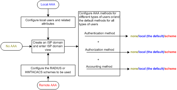
To configure AAA, complete the following tasks on the NAS:
1. Configure the required AAA schemes:
? Local authentication—Configure local users and the related attributes, including the usernames and passwords, for the users to be authenticated.
? Remote authentication—Configure the required RADIUS and HWTACACS schemes.
2. Configure AAA methods for the users' ISP domains. To use remote AAA methods, you must specify the configured RADIUS or HWTACACS schemes in the ISP domains.
Figure 8 AAA configuration procedure
To configure AAA, perform the following tasks:
|
Tasks at a glance |
|
(Required.) Perform at least one of the following tasks to configure local users or AAA schemes: |
|
(Required.) Configure AAA methods for ISP domains: 1. (Required.) Creating an ISP domain 2. (Optional.) Configuring ISP domain status 3. (Required.) Perform at least one of the following tasks to configure AAA authentication, authorization, and accounting methods for the ISP domain: ? Configuring authentication methods for an ISP domain |
|
(Optional.) Enabling the session-control feature |
|
(Optional.) Setting the maximum number of concurrent login users |
Configuring AAA schemes
This section includes information on configuring local users, RADIUS schemes, and HWTACACS schemes.
Configuring local users
To implement local authentication, authorization, and accounting, create local users and configure user attributes on the device. The local users and attributes are stored in the local user database on the device. A local user is uniquely identified by the combination of a username and a user type. The device supports only device management users who log in to the device for device management.
The following local user attributes are configurable:
· Service type—Services that the user can use. Local authentication checks the service types of a local user. If none of the service types is available, the user cannot pass authentication.
Service types include FTP, SSH, Telnet, and terminal.
· User state—Whether or not a local user can request network services. There are two user states: active and blocked. A user in active state can request network services, but a user in blocked state cannot.
· Upper limit of concurrent logins using the same user name—Maximum number of users who can concurrently access the device by using the same user name. When the number reaches the upper limit, no more local users can access the device by using the user name.
· User group—Each local user belongs to a local user group and has all attributes of the group. The attributes include the password control attributes and authorization attributes. For more information about local user group, see "Configuring user group attributes."
· Authorization attributes—Authorization attributes indicate the user's rights after it passes local authentication. Authorization attributes include the ACL, idle cut feature, user role, VLAN, and FTP/SFTP/SCP working directory. For support information about authorization attributes, see "Configuring local user attributes."
Configure the authorization attributes based on the service type of local users.
You can configure an authorization attribute in user group view or local user view. The setting of an authorization attribute in local user view takes precedence over the attribute setting in user group view.
? The attribute configured in user group view applies to all local users in the user group.
? The attribute configured in local user view applies only to the local user.
· Password control attributes—Password control attributes help control password security for device management users. Password control attributes include password aging time, minimum password length, password composition checking, password complexity checking, and login attempt limit.
You can configure a password control attribute in system view, user group view, or local user view. A password control attribute with a smaller effective range has a higher priority. For more information about password management and global password configuration, see "Configuring password control"
Local user configuration task list
|
Tasks at a glance |
|
(Required.) Configuring local user attributes |
|
(Optional.) Configuring user group attributes |
|
(Optional.) Displaying and maintaining local users and local user groups |
Configuring local user attributes
When you configure local user attributes, follow these guidelines:
· When you use the password-control enable command to globally enable the password control feature, local user passwords are not displayed.
· You can configure authorization attributes and password control attributes in local user view or user group view. The setting in local user view takes precedence over the setting in user group view.
· Configure authorization attributes according to the application environments and purposes. Support for authorization attributes depends on the service types of users.
? For Telnet and terminal users, only the authorization attributes idle-cut and user-role are effective.
? For SSH users, only the authorization attributes idle-cut, user-role, and work-directory are effective.
? For FTP users, only the authorization attributes user-role and work-directory are effective.
? For other types of local users, no authorization attribute takes effect.
To configure local user attributes:
|
Step |
Command |
Remarks |
|
1. Enter system view. |
system-view |
N/A |
|
2. Add a local user and enter local user view. |
local-user user-name [ class manage ] |
By default, no local user exists. |
|
3. (Optional.) Configure a password for the local user. |
·
In non-FIPS mode: ·
In FIPS mode: |
The password is encrypted with the hash algorithm and saved in ciphertext. In non-FIPS mode, a non-password-protected user passes authentication if the user provides the correct username and passes attribute checks. To enhance security, configure a password for each local user. In FIPS mode, only password-protected users can pass authentication. |
|
4. Assign services to the local user. |
·
In non-FIPS mode: ·
In FIPS mode: |
By default, no service is authorized to a local user. |
|
5. (Optional.) Place the local user to the active or blocked state. |
state { active | block } |
By default, a created local user is in active state and can request network services. |
|
6. (Optional.) Set the upper limit of concurrent logins using the local user name. |
access-limit max-user-number |
By default, the number of concurrent logins is not limited for the local user. This command takes effect only when local accounting is configured for the local user. It does not apply to FTP, SFTP, or SCP users, who do not support accounting. |
|
7. (Optional.) Configure authorization attributes for the local user. |
authorization-attribute { acl acl-number | idle-cut minute | user-role role-name | vlan vlan-id | work-directory directory-name } * |
The following default settings apply: · FTP, SFTP, and SCP users have the root directory of the NAS set as the working directory. However, the users do not have permission to access the root directory. · The network-operator user role is assigned to local users that are created by a network-admin or level-15 user on the default MDC. · The mdc-operator user role is assigned to local users that are created by an mdc-admin or level-15 user on a non-default MDC. |
|
8. (Optional.) Configure password control attributes for the local user. |
·
Set the password aging time: ·
Set the minimum password length: ·
Configure the password composition policy: ·
Configure the password complexity
checking policy: ·
Configure the maximum login attempts
and the action to take if there is a login failure: |
Optional. By default, the local user uses password control attributes of the user group to which the local user belongs. |
|
9. (Optional.) Assign the local user to a user group. |
group group-name |
By default, a local user belongs to the default user group system. |
Configuring user group attributes
User groups simplify local user configuration and management. A user group contains a group of local users and has a set of local user attributes. You can configure local user attributes for a user group to implement centralized user attributes management for the local users in the group. Local user attributes that are manageable include authorization attributes.
By default, every new local user belongs to the default user group system and has all attributes of the group. To assign a local user to a different user group, use the group command in local user view.
To configure user group attributes:
|
Step |
Command |
Remarks |
|
1. Enter system view. |
system-view |
N/A |
|
2. Create a user group and enter user group view. |
user-group group-name |
By default, there is a system-defined user group named system, which is the default user group. |
|
3. Configure authorization attributes for the user group. |
authorization-attribute { acl acl-number | idle-cut minute | vlan vlan-id | work-directory directory-name } * |
By default, no authorization attribute is configured for a user group. |
|
4. (Optional.) Configure password control attributes for the user group. |
·
Set the password aging time: ·
Set the minimum password length: ·
Configure the password composition policy: ·
Configure the password complexity
checking policy: ·
Configure the maximum login attempts
and the action to take for login failures: |
Optional. By default, the user group uses the global password control settings. For more information, see "Configuring password control" |
Displaying and maintaining local users and local user groups
Execute display commands in any view.
|
Task |
Command |
|
Display the local user configuration and online user statistics. |
display local-user [ class manage | idle-cut { disable | enable } | service-type { ftp | ssh | telnet | terminal } | state { active | block } | user-name user-name | vlan vlan-id ] |
|
Display the user group configuration. |
display user-group [ group-name ] |
Configuring RADIUS schemes
A RADIUS scheme specifies the RADIUS servers that the device can work with and defines a set of parameters. The device uses the parameters to exchange information with the RADIUS servers, including the IP addresses of the servers, UDP port numbers, shared keys, and server types.
Configuration task list
|
Tasks at a glance |
|
(Required.) Creating a RADIUS scheme |
|
(Required.) Specifying the RADIUS authentication servers |
|
(Optional.) Specifying the RADIUS accounting servers and the relevant parameters |
|
(Optional.) Specifying the shared keys for secure RADIUS communication |
|
(Optional.) Specifying a VPN for the scheme |
|
(Optional.) Setting the username format and traffic statistics units |
|
(Optional.) Setting the maximum number of RADIUS request transmission attempts |
|
(Optional.) Setting the status of RADIUS servers |
|
(Optional.) Specifying the source IP address for outgoing RADIUS packets |
|
(Optional.) Setting RADIUS timers |
|
(Optional.) Configuring the accounting-on feature |
|
(Optional.) Configuring the IP addresses of the security policy servers |
|
(Optional.) Configuring the Login-Service attribute check method for SSH, FTP, and terminal users |
|
(Optional.) Enabling SNMP notifications for RADIUS |
|
(Optional.) Displaying and maintaining RADIUS |
Creating a RADIUS scheme
Create a RADIUS scheme before performing any other RADIUS configurations. You can configure a maximum of 16 RADIUS schemes. A RADIUS scheme can be used by multiple ISP domains.
To create a RADIUS scheme:
|
Step |
Command |
Remarks |
|
1. Enter system view. |
system-view |
N/A |
|
2. Create a RADIUS scheme and enter RADIUS scheme view. |
radius scheme radius-scheme-name |
By default, no RADIUS scheme is defined. |
Specifying the RADIUS authentication servers
A RADIUS authentication server completes authentication and authorization together, because authorization information is piggybacked in authentication responses sent to RADIUS clients.
You can specify one primary authentication server and a maximum of 16 secondary authentication servers for a RADIUS scheme. When the primary server is not available, the device searches for the secondary servers in the order they are configured. The first secondary server in active state is used for communication.
If redundancy is not required, specify only the primary server. A RADIUS authentication server can act as the primary authentication server for one scheme and a secondary authentication server for another scheme at the same time.
To specify RADIUS authentication servers for a RADIUS scheme:
|
Step |
Command |
Remarks |
|
1. Enter system view. |
system-view |
N/A |
|
2. Enter RADIUS scheme view. |
radius scheme radius-scheme-name |
N/A |
|
3. Specify RADIUS authentication servers. |
·
Specify the primary RADIUS authentication
server: ·
Specify a secondary RADIUS authentication server: |
By default, no authentication server is specified. Two authentication servers in a scheme, primary or secondary, cannot have the same combination of hostname, IP address, port number, and VPN. |
Specifying the RADIUS accounting servers and the relevant parameters
You can specify one primary accounting server and a maximum of 16 secondary accounting servers for a RADIUS scheme. When the primary server is not available, the device searches for the secondary servers in the order they are configured. The first secondary server in active state is used for communication.
If redundancy is not required, specify only the primary server. A RADIUS accounting server can act as the primary accounting server for one scheme and a secondary accounting server for another scheme at the same time.
The device sends a stop-accounting request to the accounting server in the following situations:
· The device receives a connection teardown request from a host.
· The device receives a connection teardown command from an administrator.
When the maximum number of real-time accounting attempts is reached, the device disconnects users who have no accounting responses.
RADIUS does not support accounting for FTP, SFTP, and SCP users.
To specify RADIUS accounting servers and the relevant parameters for a RADIUS scheme:
|
Step |
Command |
Remarks |
|
1. Enter system view. |
system-view |
N/A |
|
2. Enter RADIUS scheme view. |
radius scheme radius-scheme-name |
N/A |
|
3. Specify RADIUS accounting servers. |
·
Specify the primary RADIUS accounting server: ·
Specify a secondary RADIUS accounting server: |
By default, no accounting server is specified. Two accounting servers in a scheme, primary or secondary, cannot have the same combination of hostname, IP address, port number, and VPN. |
|
4. (Optional.) Set the maximum number of real-time accounting attempts. |
retry realtime-accounting retry-times |
The default setting is 5. |
Specifying the shared keys for secure RADIUS communication
The RADIUS client and server use the MD5 algorithm and shared keys to generate the Authenticator value for packet authentication and user password encryption. The client and server must use the same key for each type of communication.
A key configured in this task is for all servers of the same type (accounting or authentication) in the scheme. The key has a lower priority than a key configured individually for a RADIUS server.
To specify a shared key for secure RADIUS communication:
|
Step |
Command |
Remarks |
|
1. Enter system view. |
system-view |
N/A |
|
2. Enter RADIUS scheme view. |
radius scheme radius-scheme-name |
N/A |
|
3. Specify a shared key for secure RADIUS communication. |
key { accounting | authentication } { cipher | simple } string |
By default, no shared key is specified. The shared key configured on the device must be the same as the shared key configured on the RADIUS server. |
Specifying a VPN for the scheme
The VPN specified for a RADIUS scheme applies to all authentication and accounting servers in that scheme. If a VPN is also configured for an individual RADIUS server, the VPN specified for the RADIUS scheme does not take effect on that server.
To specify a VPN for a scheme:
|
Step |
Command |
Remarks |
|
1. Enter system view. |
system-view |
N/A |
|
2. Enter RADIUS scheme view. |
radius scheme radius-scheme-name |
N/A |
|
3. Specify a VPN for the RADIUS scheme. |
vpn-instance vpn-instance-name |
By default, a RADIUS scheme belongs to the public network. |
Setting the username format and traffic statistics units
A username is in the userid@isp-name format, where the isp-name argument represents the user's ISP domain name. By default, the ISP domain name is included in a username. However, older RADIUS servers might not recognize usernames that contain the ISP domain names. In this case, you can configure the device to remove the domain name of each username to be sent.
If two or more ISP domains use the same RADIUS scheme, configure the RADIUS scheme to keep the ISP domain name in usernames for domain identification.
The device reports online user traffic statistics in accounting packets. The traffic measurement units are configurable, but they must be the same as the traffic measurement units configured on the RADIUS accounting servers.
To set the username format and the traffic statistics units for a RADIUS scheme:
|
Step |
Command |
Remarks |
|
1. Enter system view. |
system-view |
N/A |
|
2. Enter RADIUS scheme view. |
radius scheme radius-scheme-name |
N/A |
|
3. Set the format for usernames sent to the RADIUS servers. |
user-name-format { keep-original | with-domain | without-domain } |
By default, the ISP domain name is included in a username. |
|
4. (Optional.) Set the data flow and packet measurement units for traffic statistics. |
data-flow-format { data { byte | giga-byte | kilo-byte | mega-byte } | packet { giga-packet | kilo-packet | mega-packet | one-packet } }* |
By default, traffic is counted in bytes and packets. |
Setting the maximum number of RADIUS request transmission attempts
RADIUS uses UDP packets to transfer data. Because UDP communication is not reliable, RADIUS uses a retransmission mechanism to improve reliability. A RADIUS request is retransmitted if the NAS does not receive a server response for the request within the response timeout timer. For more information about the RADIUS server response timeout timer, see "Setting RADIUS timers."
You can set the maximum number for the NAS to retransmit a RADIUS request to the same server. When the maximum number is reached, the NAS tries to communicate with other RADIUS servers in active state. If no other servers are in active state at the time, the NAS considers the authentication or accounting attempt a failure.
To set the maximum number of RADIUS request transmission attempts:
|
Step |
Command |
Remarks |
|
1. Enter system view. |
system-view |
N/A |
|
2. Enter RADIUS scheme view. |
radius scheme radius-scheme-name |
N/A |
|
3. Set the maximum number of RADIUS request transmission attempts. |
retry retry-times |
The default setting is 3. |
Setting the status of RADIUS servers
To control the RADIUS servers with which the device communicates when the current servers are no longer available, set the status of RADIUS servers to blocked or active. You can specify one primary RADIUS server and multiple secondary RADIUS servers. The secondary servers act as the backup of the primary server. The device chooses servers based on the following rules:
· When the primary server is in active state, the device communicates with the primary server.
· If the primary server fails, the device performs the following operations:
? Changes the server status to blocked.
? Starts a quiet timer for the server.
? Tries to communicate with a secondary server in active state that has the highest priority.
· If the secondary server is unreachable, the device performs the following operations:
? Changes the server status to blocked.
? Starts a quiet timer for the server.
? Tries to communicate with the next secondary server in active state that has the highest priority.
· The search process continues until the device finds an available secondary server or has checked all secondary servers in active state. If no server is available, the device considers the authentication or accounting attempt a failure.
· When the quiet timer of a server expires or you manually set the server to the active state, the status of the server changes back to active. The device does not check the server again during the authentication or accounting process.
· When you remove a server in use, communication with the server times out. The device looks for a server in active state by first checking the primary server, and then checking secondary servers in the order they are configured.
· When all servers are in blocked state, the device only tries to communicate with the primary server.
· When one or more servers are in active state, the device tries to communicate with these active servers only, even if the servers are unavailable.
· When the status of a RADIUS server changes automatically, the device changes the status of this server accordingly in all RADIUS schemes in which this server is specified.
By default, the device sets the status of all RADIUS servers to active. However, in some situations, you must change the status of a server. For example, if a server fails, you can change the status of the server to blocked to avoid communication attempts to the server.
To set the status of RADIUS servers:
|
Step |
Command |
Remarks |
|
1. Enter system view. |
system-view |
N/A |
|
2. Enter RADIUS scheme view. |
radius scheme radius-scheme-name |
N/A |
|
3. Set the RADIUS server status. |
·
Set the status of the primary RADIUS
authentication server: ·
Set the status of the primary RADIUS
accounting server: ·
Set the status of a secondary RADIUS authentication server: ·
Set the status of a secondary RADIUS accounting server: |
By default, every server specified in a RADIUS scheme is in active state. The configured server status cannot be saved to any configuration file, and can only be viewed by using the display radius scheme command. After the device restarts, all servers are restored to the active state. |
Specifying the source IP address for outgoing RADIUS packets
The source IP address of RADIUS packets that a NAS sends must match the IP address of the NAS configured on the RADIUS server. A RADIUS server identifies a NAS by its IP address. Upon receiving a RADIUS packet, a RADIUS server checks whether the source IP address of the packet is the IP address of a managed NAS.
· If the source IP address of the packet is the IP address of a managed NAS, the server processes the packet.
· If the source IP address of the packet is not the IP address of a managed NAS, the server drops the packet.
The source address of outgoing RADIUS packets is typically the IP address of an egress interface on the NAS to communicate with the RADIUS server. However, in some situations, you must change the source IP address. For example, when VRRP is configured for stateful failover, configure the virtual IP address of the uplink VRRP group as the source IP address.
You can specify a source IP address for outgoing RADIUS packets in RADIUS scheme view or in system view.
· The IP address specified in RADIUS scheme view applies only to one RADIUS scheme.
· The IP address specified in system view applies to all RADIUS schemes whose servers are in a VPN or the public network.
Before sending a RADIUS packet, the NAS selects a source IP address in the following order:
1. The source IP address specified for the RADIUS scheme.
2. The source IP address specified in system view for the VPN or public network, depending on where the RADIUS server resides.
3. The IP address of the outbound interface specified by the route.
To specify a source IP address for all RADIUS schemes in a VPN or the public network:
|
Step |
Command |
Remarks |
|
1. Enter system view. |
system-view |
N/A |
|
2. Specify a source IP address for outgoing RADIUS packets. |
radius nas-ip ipv4-address [ vpn-instance vpn-instance-name ] |
By default, the IP address of the RADIUS packet outbound interface is used as the source IP address. |
To specify a source IP address for a RADIUS scheme:
|
Step |
Command |
Remarks |
|
1. Enter system view. |
system-view |
N/A |
|
2. Enter RADIUS scheme view. |
radius scheme radius-scheme-name |
N/A |
|
3. Specify a source IP address for outgoing RADIUS packets. |
nas-ip ipv4-address |
By default, the source IP address specified by the radius nas-ip command in system view is used. If the source IP address is not specified, the IP address of the outbound interface is used. |
Setting RADIUS timers
The device uses the following types of timers to control communication with a RADIUS server:
· Server response timeout timer (response-timeout)—Defines the RADIUS request retransmission interval. The timer starts immediately after a RADIUS request is sent. If the device does not receive a response from the RADIUS server before the timer expires, it resends the request.
· Server quiet timer (quiet)—Defines the duration to keep an unreachable server in blocked state. If one server is not reachable, the device changes the server status to blocked, starts this timer for the server, and tries to communicate with another server in active state. After the server quiet timer expires, the device changes the status of the server back to active.
· Real-time accounting timer (realtime-accounting)—Defines the interval at which the device sends real-time accounting packets to the RADIUS accounting server for online users.
When you set RADIUS timers, follow these guidelines:
· Consider the number of secondary servers when you configure the maximum number of RADIUS packet transmission attempts and the RADIUS server response timeout timer. If the RADIUS scheme includes many secondary servers, the retransmission process might be too long and the client connection in the access module, such as Telnet, can time out.
· When the client connections have a short timeout period, a large number of secondary servers can cause the initial authentication or accounting attempt to fail. In this case, reconnect the client rather than adjusting the RADIUS packet transmission attempts and server response timeout timer. Typically, the next attempt will succeed, because the device has blocked the unreachable servers to shorten the time to find a reachable server.
· Make sure the server quiet timer is set correctly. A timer that is too short might result in frequent authentication or accounting failures. The reason is that the device will continue to attempt to communicate with an unreachable server that is in active state. A timer that is too long might temporarily block a reachable server that has recovered from a failure. The reason is that the server will remain in blocked state until the timer expires.
· A short real-time accounting interval helps improve accounting precision but requires many system resources. When there are 1000 or more users, set the interval to 15 minutes or longer.
To set RADIUS timers:
|
Step |
Command |
Remarks |
|
1. Enter system view. |
system-view |
N/A |
|
2. Enter RADIUS scheme view. |
radius scheme radius-scheme-name |
N/A |
|
3. Set the RADIUS server response timeout timer. |
timer response-timeout seconds |
The default setting is 3 seconds. |
|
4. Set the quiet timer for the servers. |
timer quiet minutes |
The default setting is 5 minutes. |
|
5. Set the real-time accounting timer. |
timer realtime-accounting minutes |
The default setting is 12 minutes. |
Configuring the accounting-on feature
When the accounting-on feature is enabled, the device automatically sends an accounting-on packet to the RADIUS server after a device or card reboot. Upon receiving the accounting-on packet, the RADIUS server logs out all online users so they can log in again through the device. Without this feature, users cannot log in again after the reboot, because the RADIUS server considers them to come online.
You can configure the interval for which the device waits to resend the accounting-on packet and the maximum number of retries.
The RADIUS server must run on IMC to correctly log out users when a card reboots on the distributed device to which the users connect.
To configure the accounting-on feature for a RADIUS scheme:
|
Step |
Command |
Remarks |
|
1. Enter system view. |
system-view |
N/A |
|
2. Enter RADIUS scheme view. |
radius scheme radius-scheme-name |
N/A |
|
3. Enable accounting-on. |
accounting-on enable [ interval seconds | send send-times ] * |
By default, the accounting-on feature is disabled. |
Configuring the IP addresses of the security policy servers
The NAS verifies the validity of received control packets and accepts only control packets from known servers. To use a security policy server that is independent of the AAA servers, configure the IP address of the security policy server on the NAS.
The security policy server is the management and control center of the H3C EAD solution. To implement all EAD functions, configure both the IP address of the security policy server and that of the IMC Platform on the NAS.
To configure the IP address of a security policy server for a scheme:
|
Step |
Command |
Remarks |
|
1. Enter system view. |
system-view |
N/A |
|
2. Enter RADIUS scheme view. |
radius scheme radius-scheme-name |
N/A |
|
3. Specify a security policy server. |
security-policy-server ipv4-address [ vpn-instance vpn-instance-name ] |
By default, no security policy server is specified for a scheme. You can specify a maximum of eight security policy servers for a RADIUS scheme. |
Configuring the Login-Service attribute check method for SSH, FTP, and terminal users
The device supports the following check methods for the Login-Service attribute (RADIUS attribute 15) of SSH, FTP, and terminal users:
· Strict—Matches Login-Service attribute values 50, 51, and 52 for SSH, FTP, and terminal services, respectively.
· Loose—Matches the standard Login-Service attribute value 0 for SSH, FTP, and terminal services.
An Access-Accept packet received for a user must contain the matching attribute value. Otherwise, the user cannot log in to the device.
Use the loose check method only when the server does not issue Login-Service attribute values 50, 51, and 52 for SSH, FTP, and terminal users.
To configure the Login-Service attribute check method for SSH, FTP, and terminal users:
|
Step |
Command |
Remarks |
|
1. Enter system view. |
system-view |
N/A |
|
2. Enter RADIUS scheme view. |
radius scheme radius-scheme-name |
N/A |
|
3. Configure the Login-Service attribute check method for SSH, FTP, and terminal users. |
attribute 15 check-mode { loose | strict } |
The default check method is strict. |
Enabling SNMP notifications for RADIUS
When SNMP notifications are enabled for RADIUS, the SNMP agent supports the following notifications generated by RADIUS:
· RADIUS server unreachable notification—The RADIUS server cannot be reached. RADIUS generates this notification if it cannot receive any response to an accounting or authentication request within the specified RADIUS request transmission attempts.
· RADIUS server reachable notification—The RADIUS server can be reached. RADIUS generates this notification for a previously blocked RADIUS server after the quiet timer expires.
· Excessive authentication failures notification—The number of authentication failures to the total number of authentication attempts exceeds the specified threshold.
You can configure SNMP parameters to control the output of these SNMP notifications. For more information, see Network Management and Monitoring Configuration Guide.
To enable SNMP notifications for RADIUS:
|
Step |
Command |
Remarks |
|
1. Enter system view. |
system-view |
N/A |
|
2. Enable SNMP notifications for RADIUS. |
snmp-agent trap enable radius [ accounting-server-down | authentication-error-threshold | authentication-server-down | accounting-server-up | authentication-server-up ] * |
By default, all types of SNMP notifications are enabled for RADIUS. |
Displaying and maintaining RADIUS
Execute display commands in any view and reset commands in user view.
|
Task |
Command |
|
Display the RADIUS scheme configuration. |
display radius scheme [ radius-scheme-name ] |
|
Display RADIUS packet statistics. |
display radius statistics |
|
Clear RADIUS statistics. |
reset radius statistics |
Configuring HWTACACS schemes
Configuration task list
|
Tasks at a glance |
|
(Required.) Creating an HWTACACS scheme |
|
(Required.) Specifying the HWTACACS authentication servers |
|
(Optional.) Specifying the HWTACACS authorization servers |
|
(Optional.) Specifying the HWTACACS accounting servers |
|
(Required.) Specifying the shared keys for secure HWTACACS communication |
|
(Optional.) Specifying a VPN for the scheme |
|
(Optional.) Setting the username format and traffic statistics units |
|
(Optional.) Specifying the source IP address for outgoing HWTACACS packets |
|
(Optional.) Setting HWTACACS timers |
|
(Optional.) Displaying and maintaining HWTACACS |
Creating an HWTACACS scheme
Create an HWTACACS scheme before performing any other HWTACACS configurations. You can configure a maximum of 16 HWTACACS schemes. An HWTACACS scheme can be used by multiple ISP domains.
To create an HWTACACS scheme:
|
Step |
Command |
Remarks |
|
1. Enter system view. |
system-view |
N/A |
|
2. Create an HWTACACS scheme and enter HWTACACS scheme view. |
hwtacacs scheme hwtacacs-scheme-name |
By default, no HWTACACS scheme is defined. |
Specifying the HWTACACS authentication servers
You can specify one primary authentication server and a maximum of 16 secondary authentication servers for an HWTACACS scheme. When the primary server is not available, the device searches for the secondary servers in the order they are configured. The first secondary server in active state is used for communication.
If redundancy is not required, specify only the primary server. An HWTACACS server can act as the primary authentication server in one scheme and as the secondary authentication server in another scheme at the same time.
To specify HWTACACS authentication servers for an HWTACACS scheme:
|
Step |
Command |
Remarks |
|
1. Enter system view. |
system-view |
N/A |
|
2. Enter HWTACACS scheme view. |
hwtacacs scheme hwtacacs-scheme-name |
N/A |
|
3. Specify HWTACACS authentication servers. |
·
Specify the primary HWTACACS authentication
server: ·
Specify a secondary HWTACACS authentication server: |
By default, no authentication server is specified. Two HWTACACS authentication servers in a scheme, primary or secondary, cannot have the same combination of hostname, IP address, port number, and VPN. |
Specifying the HWTACACS authorization servers
You can specify one primary authorization server and a maximum of 16 secondary authorization servers for an HWTACACS scheme. When the primary server is not available, the device searches for the secondary servers in the order they are configured. The first secondary server in active state is used for communication.
If redundancy is not required, specify only the primary server. An HWTACACS server can act as the primary authorization server of one scheme and as the secondary authorization server of another scheme at the same time.
To specify HWTACACS authorization servers for an HWTACACS scheme:
|
Step |
Command |
Remarks |
|
1. Enter system view. |
system-view |
N/A |
|
2. Enter HWTACACS scheme view. |
hwtacacs scheme hwtacacs-scheme-name |
N/A |
|
3. Specify HWTACACS authorization servers. |
·
Specify the primary HWTACACS authorization
server: ·
Specify a secondary HWTACACS authorization server: |
By default, no authorization server is specified. Two HWTACACS authorization servers in a scheme, primary or secondary, cannot have the same combination of hostname, IP address, port number, and VPN. |
Specifying the HWTACACS accounting servers
You can specify one primary accounting server and a maximum of 16 secondary accounting servers for an HWTACACS scheme. When the primary server is not available, the device searches for the secondary servers in the order they are configured. The first secondary server in active state is used for communication.
If redundancy is not required, specify only the primary server. An HWTACACS server can act as the primary accounting server of one scheme and as the secondary accounting server of another scheme at the same time.
HWTACACS does not support accounting for FTP, SFTP, and SCP users.
To specify HWTACACS accounting servers for an HWTACACS scheme:
|
Step |
Command |
Remarks |
|
1. Enter system view. |
system-view |
N/A |
|
2. Enter HWTACACS scheme view. |
hwtacacs scheme hwtacacs-scheme-name |
N/A |
|
3. Specify HWTACACS accounting servers. |
·
Specify the primary HWTACACS accounting
server: ·
Specify a
secondary HWTACACS accounting server: |
By default, no accounting server is specified. Two HWTACACS accounting servers in a scheme, primary or secondary, cannot have the same combination of hostname, IP address, port number, and VPN. |
Specifying the shared keys for secure HWTACACS communication
The HWTACACS client and server use the MD5 algorithm and shared keys to generate the Authenticator value for packet authentication and user password encryption. The client and server must use the same key for each type of communication.
To specify a shared key for secure HWTACACS communication:
|
Step |
Command |
Remarks |
|
1. Enter system view. |
system-view |
N/A |
|
2. Enter HWTACACS scheme view. |
hwtacacs scheme hwtacacs-scheme-name |
N/A |
|
3. Specify a shared key for secure HWTACACS authentication, authorization, or accounting communication. |
key { accounting | authentication | authorization } { cipher | simple } string |
By default, no shared key is specified. The shared key configured on the device must be the same as the shared key configured on the HWTACACS server. |
Specifying a VPN for the scheme
The VPN specified for an HWTACACS scheme applies to all servers in that scheme. If a VPN is also configured for an individual HWTACACS server, the VPN specified for the HWTACACS scheme does not take effect on that server.
To specify a VPN for an HWTACACS scheme:
|
Step |
Command |
Remarks |
|
1. Enter system view. |
system-view |
N/A |
|
2. Enter HWTACACS scheme view. |
hwtacacs scheme hwtacacs-scheme-name |
N/A |
|
3. Specify a VPN for the HWTACACS scheme. |
vpn-instance vpn-instance-name |
By default, an HWTACACS scheme belongs to the public network. |
Setting the username format and traffic statistics units
A username is in the userid@isp-name format, where the isp-name argument represents the user's ISP domain name. By default, the ISP domain name is included in a username. If HWTACACS servers do not recognize usernames that contain ISP domain names, you can configure the device to send usernames without domain names to the servers.
If two or more ISP domains use the same HWTACACS scheme, configure the scheme to keep the ISP domain name in usernames for domain identification.
The device reports online user traffic statistics in accounting packets. The traffic measurement units are configurable, but they must be the same as the traffic measurement units configured on the HWTACACS accounting servers.
To set the username format and traffic statistics units for an HWTACACS scheme:
|
Step |
Command |
Remarks |
|
1. Enter system view. |
system-view |
N/A |
|
2. Enter HWTACACS scheme view. |
hwtacacs scheme hwtacacs-scheme-name |
N/A |
|
3. Set the format of usernames sent to the HWTACACS servers. |
user-name-format { keep-original | with-domain | without-domain } |
By default, the ISP domain name is included in a username. |
|
4. (Optional.) Set the data flow and packet measurement units for traffic statistics. |
data-flow-format { data { byte | giga-byte | kilo-byte | mega-byte } | packet { giga-packet | kilo-packet | mega-packet | one-packet } }* |
By default, traffic is counted in bytes and packets. |
Specifying the source IP address for outgoing HWTACACS packets
The source IP address of HWTACACS packets that a NAS sends must match the IP address of the NAS configured on the HWTACACS server. An HWTACACS server identifies a NAS by IP address. When the HWTACACS server receives a packet, it checks whether the source IP address of the packet is the IP address of a managed NAS.
· If the source IP address of the packet is the IP address of a managed NAS, the server processes the packet.
· If the source IP address of the packet is not the IP address of a managed NAS, the server drops the packet.
To communicate with the HWTACACS server, the source address of outgoing HWTACACS packets is typically the IP address of an egress interface on the NAS. However, in some situations, you must change the source IP address. For example, when VRRP is configured for stateful failover, configure the virtual IP address of the uplink VRRP group as the source IP address.
You can specify the source IP address for outgoing HWTACACS packets in HWTACACS scheme view or in system view.
· The IP address specified in HWTACACS scheme view applies to one HWTACACS scheme.
· The IP address specified in system view applies to all HWTACACS schemes whose servers are in a VPN or the public network.
Before sending an HWTACACS packet, the NAS selects a source IP address in the following order:
1. The source IP address specified for the HWTACACS scheme.
2. The source IP address specified in system view for the VPN or public network, depending on where the HWTACACS server resides.
3. The IP address of the outbound interface specified by the route.
To specify a source IP address for all HWTACACS schemes of a VPN or the public network:
|
Step |
Command |
Remarks |
|
1. Enter system view. |
system-view |
N/A |
|
2. Specify a source IP address for outgoing HWTACACS packets. |
hwtacacs nas-ip ipv4-address [ vpn-instance vpn-instance-name ] |
By default, the IP address of the HWTACACS packet outbound interface is used as the source IP address. |
To specify a source IP address for an HWTACACS scheme:
|
Step |
Command |
Remarks |
|
1. Enter system view. |
system-view |
N/A |
|
2. Enter HWTACACS scheme view. |
hwtacacs scheme hwtacacs-scheme-name |
N/A |
|
3. Specify the source IP address of outgoing HWTACACS packets. |
nas-ip ipv4-address |
By default, the source IP address specified by the hwtacacs nas-ip command in system view is used. If the source IP address is not specified, the IP address of the outbound interface is used. |
Setting HWTACACS timers
The device uses the following timers to control communication with an HWTACACS server:
· Server response timeout timer (response-timeout)—Defines the HWTACACS server response timeout timer. The device starts this timer immediately after an HWTACACS authentication, authorization, or accounting request is sent. If the device does not receive a response from the server within the timer, it sets the server to the blocked state and resends the request to another HWTACACS server.
· Real-time accounting timer (realtime-accounting)—Defines the interval at which the device sends real-time accounting packets to the HWTACACS accounting server for online users.
· Server quiet timer (quiet)—Defines the duration to keep an unreachable server in blocked state. If a server is not reachable, the device changes the server status to blocked, starts this timer for the server, and tries to communicate with another server in active state. After the server quiet timer expires, the device changes the status of the server back to active.
The server quiet timer setting affects the status of HWTACACS servers. If the scheme includes one primary HWTACACS server and multiple secondary HWTACACS servers, the device communicates with the HWTACACS servers based on the following rules:
· When the primary server is in active state, the device communicates with the primary server.
· If the primary server fails, the device performs the following operations:
? Changes the server status to blocked.
? Starts a quiet timer for the server.
? Tries to communicate with a secondary server in active state that has the highest priority.
· If the secondary server is unreachable, the device performs the following operations:
? Changes the server status to blocked.
? Starts a quiet timer for the server.
? Tries to communicate with the next secondary server in active state that has the highest priority.
· The search process continues until the device finds an available secondary server or has checked all secondary servers in active state. If no server is available, the device considers the authentication, authorization, or accounting attempt a failure.
· When the quiet timer of a server expires, the status of the server changes back to active. The device does not check the server again during the authentication, authorization, or accounting process.
· When you remove a server in use, communication with the server times out. The device looks for a server in active state by first checking the primary server, and then checking secondary servers in the order they are configured.
· When all servers are in blocked state, the device only tries to communicate with the primary server.
· When one or more servers are in active state, the device tries to communicate with these active servers only, even if they are unavailable.
· When the status of an HWTACACS server changes automatically, the device changes the status of this server accordingly in all HWTACACS schemes in which this server is specified.
To set HWTACACS timers:
|
Step |
Command |
Remarks |
|
1. Enter system view. |
system-view |
N/A |
|
2. Enter HWTACACS scheme view. |
hwtacacs scheme hwtacacs-scheme-name |
N/A |
|
3. Set the HWTACACS server response timeout timer. |
timer response-timeout seconds |
By default, the HWTACACS server response timeout timer is 5 seconds. |
|
4. Set the real-time accounting interval. |
timer realtime-accounting minutes |
By default, the real-time accounting interval is 12 minutes. A short interval helps improve accounting precision but requires many system resources. When there are 1000 or more users, set a longer interval. |
|
5. Set the server quiet timer. |
timer quiet minutes |
By default, the server quiet timer is 5 minutes. |
Displaying and maintaining HWTACACS
Execute display commands in any view and reset commands in user view.
|
Task |
Command |
|
Display the configuration or server statistics of HWTACACS schemes. |
display hwtacacs scheme [ hwtacacs-server-name [ statistics ] |
|
Clear HWTACACS statistics. |
reset hwtacacs statistics { accounting | all | authentication | authorization } |
Configuring AAA methods for ISP domains
You configure AAA methods for an ISP domain by specifying configured AAA schemes in ISP domain view. Each ISP domain has a set of system-defined AAA methods, which are local authentication, local authorization, and local accounting. If you do not configure any AAA methods for an ISP domain, the device uses the system-defined AAA methods for users in the domain.
AAA is available to login users after you enable scheme authentication for the users. For more information about the login authentication modes, see Fundamentals Configuration Guide.
Configuration prerequisites
To use local authentication for users in an ISP domain, configure local user accounts on the device first. See "Configuring local user attributes."
To use remote authentication, authorization, and accounting, create the required RADIUS and HWTACACS schemes. For more information about the scheme configuration, see "Configuring RADIUS schemes" and "Configuring HWTACACS schemes."
Creating an ISP domain
In a networking scenario with multiple ISPs, the device can connect to users of different ISPs, and these users can have different user attributes, such as different username and password structures, different service types, and different rights. To manage users of different ISPs, configure ISP domains, and configure AAA methods and domain attributes for each ISP domain as needed.
The device supports a maximum of 16 ISP domains, including the system-defined ISP domain system. You can specify one of the ISP domains as the default domain. You can modify the settings of the ISP domain system, but you cannot delete the domain.
On the device, each user belongs to an ISP domain. If a user does not provide an ISP domain name at login, the device considers the user belongs to the default ISP domain.
An ISP domain cannot be deleted when it is the default ISP domain. Before you use the undo domain command, change the domain to a non-default ISP domain by using the undo domain default enable command.
To create an ISP domain:
|
Step |
Command |
Remarks |
|
1. Enter system view. |
system-view |
N/A |
|
2. Create an ISP domain and enter ISP domain view. |
domain isp-name |
N/A |
|
3. Return to system view. |
quit |
N/A |
|
4. (Optional.) Specify the default ISP domain. |
domain default enable isp-name |
By default, the default ISP domain is the system-defined ISP domain system. |
Configuring ISP domain status
By placing the ISP domain in active or blocked state, you allow or deny network service requests from users in the domain.
|
Step |
Command |
Remarks |
|
1. Enter system view. |
system-view |
N/A |
|
2. Enter ISP domain view. |
domain isp-name |
N/A |
|
3. Place the ISP domain in active or blocked state. |
state { active | block } |
By default, an ISP domain is in active state, and users in the domain can request network services. |
Configuring authentication methods for an ISP domain
Configuration prerequisites
Before configuring authentication methods, complete the following tasks:
1. Determine the access type or service type to be configured. With AAA, you can configure an authentication method for each access type and service type.
2. Determine whether to configure the default authentication method for all access types or service types. The default authentication method applies to all access users. However, the method has a lower priority than the authentication method that is specified for an access type or service type.
Configuration guidelines
When configuring authentication methods, follow these guidelines:
· If a RADIUS scheme is used for authentication but not for authorization in an ISP domain, AAA accepts only the authentication result from the RADIUS server. The Access-Accept message from the RADIUS server also includes the authorization information, but the device ignores the information.
· To specify a scheme for user role authentication, make sure the user role is in the format of level-n. If an HWTACACS scheme is specified, the device uses the entered username for role authentication. If a RADIUS scheme is specified, the device uses the username $enabn$ on the RADIUS server for role authentication. The variable n has the same value as the variable n in the target user role level-n.
Configuration procedure
To configure authentication methods for an ISP domain:
|
Step |
Command |
Remarks |
|
1. Enter system view. |
system-view |
N/A |
|
2. Enter ISP domain view. |
domain isp-name |
N/A |
|
3. Specify the default authentication method for all types of users. |
authentication default { hwtacacs-scheme hwtacacs-scheme-name [ radius-scheme radius-scheme-name ] [ local ] [ none ] | local [ none ] | none | radius-scheme radius-scheme-name [ hwtacacs-scheme hwtacacs-scheme-name ] [ local ] [ none ] } |
By default, the default authentication method is local. The none keyword is not supported in FIPS mode. |
|
4. Specify the authentication method for login users. |
authentication login { hwtacacs-scheme hwtacacs-scheme-name [ radius-scheme radius-scheme-name ] [ local ] [ none ] | local [ none ] | none | radius-scheme radius-scheme-name [ hwtacacs-scheme hwtacacs-scheme-name ] [ local ] [ none ] } |
By default, the default authentication method is used for login users. The none keyword is not supported in FIPS mode. |
|
5. Specify the user role authentication method. |
authentication super { hwtacacs-scheme hwtacacs-scheme-name | radius-scheme radius-scheme-name } * |
By default, the default authentication method is used for user role authentication. |
Configuring authorization methods for an ISP domain
Configuration prerequisites
Before configuring authorization methods, complete the following tasks:
1. Determine the access type or service type to be configured. With AAA, you can configure an authorization scheme for each access type and service type.
2. Determine whether to configure the default authorization method for all access types or service types. The default authorization method applies to all access users. However, the method has a lower priority than the authorization method that is specified for an access type or service type.
Configuration guidelines
When configuring authorization methods, follow these guidelines:
· The device supports HWTACACS authorization.
· To use a RADIUS scheme as the authorization method, specify the same RADIUS scheme that is configured as the authentication method for the ISP domain. If an invalid RADIUS scheme is specified as the authorization method, RADIUS authentication and authorization fail.
Configuration procedure
To configure authorization methods for an ISP domain:
|
Step |
Command |
Remarks |
|
1. Enter system view. |
system-view |
N/A |
|
2. Enter ISP domain view. |
domain isp-name |
N/A |
|
3. Specify the default authorization method for all types of users. |
authorization default { hwtacacs-scheme hwtacacs-scheme-name [ radius-scheme radius-scheme-name ] [ local ] [ none ] | local [ none ] | none | radius-scheme radius-scheme-name [ hwtacacs-scheme hwtacacs-scheme-name ] [ local ] [ none ] } |
By default, the authorization method is local. The none keyword is not supported in FIPS mode. |
|
4. Specify the command authorization method. |
authorization command { hwtacacs-scheme hwtacacs-scheme-name [ local [ none ] | local [ none ] | none } |
By default, the default authorization method is used for command authorization. The none keyword is not supported in FIPS mode. |
|
5. Specify the authorization method for login users. |
authorization login { hwtacacs-scheme hwtacacs-scheme-name [ radius-scheme radius-scheme-name ] [ local ] [ none ] | local [ none ] | none | radius-scheme radius-scheme-name [ hwtacacs-scheme hwtacacs-scheme-name ] [ local ] [ none ] } |
By default, the default authorization method is used for login users. The none keyword is not supported in FIPS mode. |
Configuring accounting methods for an ISP domain
Configuration prerequisites
Before configuring accounting methods, complete the following tasks:
1. Determine the access type or service type to be configured. With AAA, you can configure an accounting method for each access type and service type.
2. Determine whether to configure the default accounting method for all access types or service types. The default accounting method applies to all access users. However, the method has a lower priority than the accounting method that is specified for an access type or service type.
Configuration guidelines
When configuring accounting methods, follow these guidelines:
· FTP, SFTP, and SCP users do not support accounting.
· Local accounting does not provide statistics for charging. It only counts and controls the number of concurrent users who use the same local user account. The threshold is configured by using the access-limit command.
Configuration procedure
To configure accounting methods for an ISP domain:
|
Step |
Command |
Remarks |
|
1. Enter system view. |
system-view |
N/A |
|
2. Enter ISP domain view. |
domain isp-name |
N/A |
|
3. Specify the default accounting method for all types of users. |
accounting default { hwtacacs-scheme hwtacacs-scheme-name [ radius-scheme radius-scheme-name ] [ local ] [ none ] | local [ none ] | none | radius-scheme radius-scheme-name [ hwtacacs-scheme hwtacacs-scheme-name ] [ local ] [ none ] } |
By default, the accounting method is local. The none keyword is not supported in FIPS mode. |
|
4. Specify the command accounting method. |
accounting command hwtacacs-scheme hwtacacs-scheme-name |
By default, the default accounting method is used for command accounting. |
|
5. Specify the accounting method for login users. |
accounting login { hwtacacs-scheme hwtacacs-scheme-name [ radius-scheme radius-scheme-name ] [ local ] [ none ] | local [ none ] | none | radius-scheme radius-scheme-name [ hwtacacs-scheme hwtacacs-scheme-name ] [ local ] [ none ] } |
By default, the default accounting method is used for login users. The none keyword is not supported in FIPS mode. |
Enabling the session-control feature
A RADIUS server running on IMC can use session-control packets to inform disconnect or dynamic authorization change requests. This task enables the device to receive RADIUS session-control packets on UDP port 1812.
To enable the session-control feature:
|
Step |
Command |
Remarks |
|
1. Enter system view. |
system-view |
N/A |
|
2. Enable the session-control feature. |
radius session-control enable |
By default, the session-control feature is disabled. |
Setting the maximum number of concurrent login users
Perform this task to set the maximum number of concurrent users who can log on to the device through a specific protocol, regardless of their authentication methods. The authentication methods include no authentication, local authentication, and remote authentication.
To set the maximum number of concurrent login users:
|
Step |
Command |
Remarks |
|
1. Enter system view. |
system-view |
N/A |
|
2. Set the maximum number of concurrent login users. |
·
In non-FIPS mode: ·
In FIPS mode: |
By default, the maximum number of concurrent login users is 32 for each user type. |
Displaying and maintaining AAA
Execute display commands in any view.
|
Task |
Command |
|
Display the configuration of ISP domains. |
display domain [ isp-name ] |
AAA configuration examples
AAA for SSH users by an HWTACACS server
Network requirements
As shown in Figure 9, configure the switch to meet the following requirements:
· Use the HWTACACS server for SSH user authentication, authorization, and accounting.
· Assign the default user role network-operator to SSH users after they pass authentication.
· Exclude domain names from the usernames sent to the HWTACACS server.
· Use expert as the shared keys for secure HWTACACS communication.
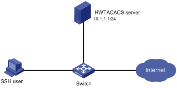
Configuration procedure
1. Configure the HWTACACS server:
# Set the shared keys for secure communication with the switch to expert. (Details not shown.)
# Add an account for the SSH user and specify the password. (Details not shown.)
2. Configure the switch:
# Assign IP addresses to the interfaces. (Details not shown.)
# Create an HWTACACS scheme.
<Switch> system-view
[Switch] hwtacacs scheme hwtac
# Specify the primary authentication server.
[Switch-hwtacacs-hwtac] primary authentication 10.1.1.1 49
# Specify the primary authorization server.
[Switch-hwtacacs-hwtac] primary authorization 10.1.1.1 49
# Specify the primary accounting server.
[Switch-hwtacacs-hwtac] primary accounting 10.1.1.1 49
# Set the shared keys for secure HWTACACS communication to expert in plain text.
[Switch-hwtacacs-hwtac] key authentication simple expert
[Switch-hwtacacs-hwtac] key authorization simple expert
[Switch-hwtacacs-hwtac] key accounting simple expert
# Exclude domain names from the usernames sent to the HWTACACS server.
[Switch-hwtacacs-hwtac] user-name-format without-domain
[Switch-hwtacacs-hwtac] quit
# Create ISP domain bbb and configure the domain to use the HWTACACS scheme for authentication, authorization, and accounting of login users.
[Switch-isp-bbb] authentication login hwtacacs-scheme hwtac
[Switch-isp-bbb] authorization login hwtacacs-scheme hwtac
[Switch-isp-bbb] accounting login hwtacacs-scheme hwtac
[Switch-isp-bbb] quit
# Create local RSA and DSA key pairs.
[Switch] public-key local create rsa
[Switch] public-key local create dsa
# Enable the SSH service.
[Switch] ssh server enable
# Enable scheme authentication for user lines VTY 0 through VTY 63.
[Switch] line vty 0 63
[Switch-line-vty0-63] authentication-mode scheme
[Switch-line-vty0-63] quit
# Enable the default user role feature to assign authenticated SSH users the default user role network-operator.
[Switch] role default-role enable
Verifying the configuration
# Initiate an SSH connection to the switch, and enter the correct username and password. The user logs in to the switch. (Details not shown.)
# Verify that the user can use the commands permitted by the network-operator user role. (Details not shown.)
Local authentication, HWTACACS authorization, and RADIUS accounting for SSH users
Network requirements
As shown in Figure 10, configure the switch to meet the following requirements:
· Perform local authentication for SSH servers.
· Use the HWTACACS server and RADIUS server for SSH user authorization and accounting, respectively.
· Exclude domain names from the usernames sent to the servers.
· Assign the default user role network-operator to SSH users after they pass authentication.
Configure an account with the username hello for the SSH user. Configure the shared keys for secure communication with the HWTACACS server and RADIUS server to expert.
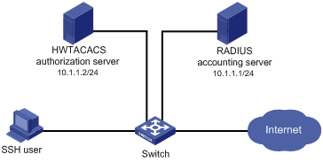
Configuration procedure
1. Configure the HWTACACS server. (Details not shown.)
2. Configure the RADIUS server. (Details not shown.)
3. Configure the switch:
# Assign IP addresses to interfaces. (Details not shown.)
# Create local RSA and DSA key pairs.
<Switch> system-view
[Switch] public-key local create rsa
[Switch] public-key local create dsa
# Enable the SSH service.
[Switch] ssh server enable
# Enable scheme authentication for user lines VTY 0 through VTY 63.
[Switch] line vty 0 63
[Switch-line-vty0-63] authentication-mode scheme
[Switch-line-vty0-63] quit
# Configure an HWTACACS scheme.
[Switch] hwtacacs scheme hwtac
[Switch-hwtacacs-hwtac] primary authorization 10.1.1.2 49
[Switch-hwtacacs-hwtac] key authorization simple expert
[Switch-hwtacacs-hwtac] user-name-format without-domain
[Switch-hwtacacs-hwtac] quit
# Configure a RADIUS scheme.
[Switch] radius scheme rd
[Switch-radius-rd] primary accounting 10.1.1.1 1813
[Switch-radius-rd] key accounting simple expert
[Switch-radius-rd] user-name-format without-domain
[Switch-radius-rd] quit
# Create a device management user.
[Switch] local-user hello class manage
# Assign the SSH service for the local user.
[Switch-luser-manage-hello] service-type ssh
# Set a password for the local user to 123456TESTplat&! in plain text. In FIPS mode, you must set the password in interactive mode.
[Switch-luser-manage-hello] password simple 123456TESTplat&!
[Switch-luser-manage-hello] quit
# Create ISP domain bbb and configure the login users to use local authentication, HWTACACS authorization, and RADIUS accounting.
[Switch] domain bbb
[Switch-isp-bbb] authentication login local
[Switch-isp-bbb] authorization login hwtacacs-scheme hwtac
[Switch-isp-bbb] accounting login radius-scheme rd
[Switch-isp-bbb] quit
# Enable the default user role feature to assign authenticated SSH users the default user role network-operator.
[Switch] role default-role enable
Verifying the configuration
# Initiate an SSH connection to the switch, and enter the username hello@bbb and the correct password. The user logs in to the switch. (Details not shown.)
# Verify that the user can use the commands permitted by the network-operator user role. (Details not shown.)
Authentication and authorization for SSH users by a RADIUS server
Network requirements
As shown in Figure 11, configure the switch to meet the following requirements:
· Use the RADIUS server for SSH user authentication and authorization.
· Include domain names in the usernames sent to the RADIUS server.
· Assign the default user role network-operator to SSH users after they pass authentication.
The RADIUS server runs on IMC. Add an account with the username hello@bbb on the RADIUS server.
The RADIUS server and the switch use expert as the shared key for secure RADIUS communication. The ports for authentication and accounting are 1812 and 1813, respectively.
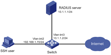
Configuration procedure
1. Configure the RADIUS server on IMC 5.0:
|
|
NOTE: In this example, the RADIUS server runs on IMC PLAT 5.0 (E0101) and IMC UAM 5.0 (E0101). |
# Add the switch to the IMC Platform as an access device.
Log in to IMC, click the Service tab, and select User Access Manager > Access Device Management > Access Device from the navigation tree. Then, click Add to configure an access device as follows:
a. Set the shared key for secure RADIUS communication to expert.
b. Set the ports for authentication and accounting to 1812 and 1813, respectively.
c. Select the service type Device Management Service.
d. Select the access device type H3C.
e. Select the access device from the device list or manually add the access device (with the IP address 10.1.1.2).
f. Leave the default settings for other parameters and click OK.
The IP address of the access device specified here must be the same as the source IP address of the RADIUS packets sent from the switch. The source IP address is chosen in the following order on the switch:
? IP address specified by the nas-ip command.
? IP address specified by the radius nas-ip command.
? IP address of the outbound interface (the default).
Figure 12 Adding the switch as an access device
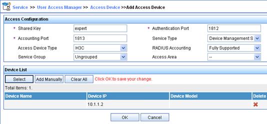
# Add an account for device management.
Click the User tab, and select Access User View > Device Mgmt User from the navigation tree. Then, click Add to configure a device management account as follows:
a. Enter the account name hello@bbb and specify the password.
b. Select the service type SSH.
c. Specify 10.1.1.0 to 10.1.1.255 as the IP address range of the hosts to be managed.
d. Click OK.
|
|
NOTE: The IP address range must contain the IP address of the switch. |
Figure 13 Adding an account for device management
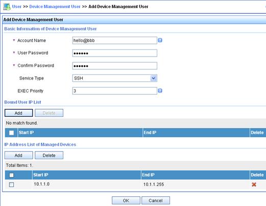
2. Configure the switch:
# Assign an IP address to VLAN-interface 2, the SSH user access interface.
<Switch> system-view
[Switch] interface vlan-interface 2
[Switch-Vlan-interface2] ip address 192.168.1.70 255.255.255.0
[Switch-Vlan-interface2] quit
# Assign an IP address to VLAN-interface 3, through which the switch communicates with the server.
[Switch] interface vlan-interface 3
[Switch-Vlan-interface3] ip address 10.1.1.2 255.255.255.0
[Switch-Vlan-interface3] quit
# Create local RSA and DSA key pairs.
[Switch] public-key local create rsa
[Switch] public-key local create dsa
# Enable the SSH service.
[Switch] ssh server enable
# Enable scheme authentication for user lines VTY 0 through VTY 63.
[Switch] line vty 0 63
[Switch-line-vty0-63] authentication-mode scheme
[Switch-line-vty0-63] quit
# Enable the default user role feature to assign authenticated SSH users the default user role network-operator.
[Switch] role default-role enable
# Create a RADIUS scheme.
[Switch] radius scheme rad
# Specify the primary authentication server.
[Switch-radius-rad] primary authentication 10.1.1.1 1812
# Set the shared key for secure communication with the server to expert in plain text.
[Switch-radius-rad] key authentication simple expert
# Include domain names in the usernames sent to the RADIUS server.
[Switch-radius-rad] user-name-format with-domain
[Switch-radius-rad] quit
# Create ISP domain bbb and configure authentication, authorization, and accounting methods for login users.
[Switch] domain bbb
[Switch-isp-bbb] authentication login radius-scheme rad
[Switch-isp-bbb] authorization login radius-scheme rad
[Switch-isp-bbb] accounting login none
[Switch-isp-bbb] quit
Verifying the configuration
# Initiate an SSH connection to the switch, and enter the username hello@bbb and the correct password. The user logs in to the switch. (Details not shown.)
# Verify that the user can use the commands permitted by the network-operator user role. (Details not shown.)
Troubleshooting RADIUS
RADIUS authentication failure
Symptom
User authentication always fails.
Analysis
Possible reasons include:
· A communication failure exists between the NAS and the RADIUS server.
· The username is not in the userid@isp-name format, or the ISP domain is not correctly configured on the NAS.
· The user is not configured on the RADIUS server.
· The password entered by the user is incorrect.
· The RADIUS server and the NAS are configured with different shared keys.
Solution
To resolve the problem:
1. Check the following items:
? The NAS and the RADIUS server can ping each other.
? The username is in the userid@isp-name format and the ISP domain is correctly configured on the NAS.
? The user is configured on the RADIUS server.
? The correct password is entered.
? The same shared key is configured on both the RADIUS server and the NAS.
2. If the problem persists, contact H3C Support.
RADIUS packet delivery failure
Symptom
RADIUS packets cannot reach the RADIUS server.
Analysis
Possible reasons include:
· A communication failure exists between the NAS and the RADIUS server.
· The NAS is not configured with the IP address of the RADIUS server.
· The authentication and accounting UDP ports configured on the NAS are incorrect.
· The RADIUS server's authentication and accounting port numbers are being used by other applications.
Solution
To resolve the problem:
1. Check the following items:
? The link between the NAS and the RADIUS server work well at both the physical and data link layers.
? The IP address of the RADIUS server is correctly configured on the NAS.
? The authentication and accounting UDP port numbers configured on the NAS are the same as those of the RADIUS server.
? The RADIUS server's authentication and accounting port numbers are available.
2. If the problem persists, contact H3C Support.
RADIUS accounting error
Symptom
A user is authenticated and authorized, but accounting for the user is not normal.
Analysis
The accounting server configuration on the NAS is not correct. Possible reasons include:
· The accounting port number configured on the NAS is incorrect.
· The accounting server IP address configured on the NAS is incorrect. For example, the NAS is configured to use a single server to provide authentication, authorization, and accounting services, but in fact the services are provided by different servers.
Solution
To resolve the problem:
1. Check the following items:
? The accounting port number is correctly configured.
? The accounting server IP address is correctly configured on the NAS.
2. If the problem persists, contact H3C Support.
Troubleshooting HWTACACS
Similar to RADIUS troubleshooting. See "Troubleshooting RADIUS."
Configuring password control
Overview
Password control allows you to implement the following features:
· Manage login and super password setup, expirations, and updates for device management users.
· Control user login status based on predefined policies.
Local users are divided into two types: device management users and network access users. This feature applies only to device management users. For more information about local users, see "Configuring AAA"
Password setting
Minimum password length
You can define the minimum length of user passwords. If a user enters a password that is shorter than the minimum length, the system rejects the password.
Password composition policy
A password can be a combination of characters from the following types:
· Uppercase letters A to Z.
· Lowercase letters a to z.
· Digits 0 to 9.
· Special characters. For information about special characters, see the password-control composition command in Security Command Reference.
Depending on the system's security requirements, you can set the minimum number of character types a password must contain and the minimum number of characters for each type, as shown in Table 4.
Table 4 Password composition policy
|
Password combination level |
Minimum number of character types |
Minimum number of characters for each type |
|
Level 1 |
One |
One |
|
Level 2 |
Two |
One |
|
Level 3 |
Three |
One |
|
Level 4 |
Four |
One |
In non-FIPS mode, all the combination levels are available for a password. In FIPS mode, only the level 4 combination is available for a password.
When a user sets or changes a password, the system checks if the password meets the combination requirement. If not, the operation fails.
Password complexity checking policy
A less complicated password such as a password containing the username or repeated characters is more likely to be cracked. For higher security, you can configure a password complexity checking policy to ensure that all user passwords are relatively complicated. With such a policy configured, when a user configures a password, the system checks the complexity of the password. If the password is complexity-incompliant, the configuration will fail.
You can apply the following password complexity requirements:
· A password cannot contain the username or the reverse of the username. For example, if the username is abc, a password such as abc982 or 2cba is not complex enough.
· A character or number cannot be included three or more times consecutively. For example, password a111 is not complex enough.
Password updating and expiration
Password updating
This feature allows you to set the minimum interval at which users can change their passwords. If a user logs in to change the password but the time passed since the last change is less than this interval, the system denies the request. For example, if you set this interval to 48 hours, a user cannot change the password twice within 48 hours.
The set minimum interval is not effective when a user is prompted to change the password at the first login or after its password aging time expires.
Password expiration
Password expiration imposes a lifecycle on a user password. After the password expires, the user needs to change the password.
If a user enters an expired password when logging in, the system displays an error message. The user is prompted to provide a new password and to confirm it by entering it again. The new password must be valid, and the user must enter exactly the same password when confirming it.
Telnet users, SSH users, and console users can change their own passwords. The administrator must change passwords for FTP users.
Early notice on pending password expiration
When a user logs in, the system checks whether the password will expire in a time equal to or less than the specified notification period. If so, the system notifies the user when the password will expire and provides a choice for the user to change the password. If the user sets a new password that is complexity-compliant, the system records the new password and the setup time. If the user chooses not to change the password or the user fails to change it, the system allows the user to log in using the current password.
Telnet users, SSH users, and console users can change their own passwords. The administrator must change passwords for FTP users.
Login with an expired password
You can allow a user to log in a certain number of times within a period of time after the password expires. For example, if you set the maximum number of logins with an expired password to 3 and the time period to 15 days, a user can log in three times within 15 days after the password expires.
Password history
With this feature enabled, the system stores passwords that a user has used. When a user changes the password, the system checks the new password against the current password and those stored in the password history records. The new password must be different from the current one and those stored in the history records by at least four characters. The four characters must be different from one another. Otherwise, the system will display an error message, and the password will not be changed.
You can set the maximum number of history password records for the system to maintain for each user. When the number of history password records exceeds your setting, the most recent record overwrites the earliest one.
Current login passwords of device management users are not stored in the password history, because a device management user password is saved in cipher text and cannot be recovered to a plaintext password.
User login control
First login
With the global password control feature enabled, users must change the password at first login before they can access the system. In this situation, password changes are not subject to the minimum change interval.
Login attempt limit
Limiting the number of consecutive login failures can effectively prevent password guessing.
Login attempt limit takes effect on FTP and VTY users. It does not take effect on the following types of users:
· Nonexistent users (users not configured on the device).
· Users logging in to the device through console ports.
If a user fails to log in, the system adds the user account and the user's IP address to the password control blacklist. After making the maximum number of consecutive attempts, login attempt limit limits the user and user account in any of the following ways:
· Disables the user account until the account is manually removed from the password control blacklist.
· Allows the user to continue using the user account. The user's IP address and user account are removed from the password control blacklist when the user uses this account to successfully log in to the device.
· Disables the user account for a period of time.
The user can use the account to log in when either of the following conditions exists:
? The locking timer expires.
? The account is manually removed from the password control blacklist before the locking timer expires.
|
|
NOTE: This account is locked only for this user. Other users can still use this account, and the blacklisted user can use other user accounts. |
Maximum account idle time
You can set the maximum account idle time for user accounts. When an account is idle for this period of time since the last successful login, the account becomes invalid.
Password not displayed in any form
For security purposes, nothing is displayed when a user enters a password.
Logging
The system logs all successful password changing events and user adding events to the password control blacklist.
FIPS compliance
The device supports the FIPS mode that complies with NIST FIPS 140-2 requirements. Support for features, commands, and parameters might differ in FIPS mode (see "Configuring FIPS") and non-FIPS mode.
Password control configuration task list
The password control features can be configured in several different views, and different views support different features. The settings configured in different views or for different objects have the following application ranges:
· Settings for super passwords apply only to super passwords.
· Settings in local user view apply only to the password of the local user.
· Settings in user group view apply to the passwords of the local users in the user group if you do not configure password policies for these users in local user view.
· Global settings in system view apply to the passwords of the local users in all user groups if you do not configure password policies for these users in both local user view and user group view.
For local user passwords, the settings with a smaller application scope have higher priority.
To configure password control, perform the following tasks:
|
Tasks at a glance |
|
(Required.) Enabling password control |
|
(Optional.) Setting global password control parameters |
|
(Optional.) Setting user group password control parameters |
|
(Optional.) Setting local user password control parameters |
|
(Optional.) Setting super password control parameters |
Enabling password control
Enabling the global password control feature is the prerequisite for all password control configurations to take effect. Then, for a specific password control feature to take effect, enable this password control feature.
After the global password control feature is enabled, you cannot display the password and super password configurations for device management users by using the corresponding display commands. However, the configuration for network access user passwords can be displayed. The first password configured for device management users must contain at least four different characters.
To enable password control:
|
Step |
Command |
Remarks |
|
system-view |
N/A |
|
|
2. Enable the global password control feature. |
password-control enable |
· In non-FIPS mode, the global password control feature is disabled by default. · In FIPS mode, the global password control feature is enabled and cannot be disabled by default. |
|
3. (Optional.) Enable a specific password control feature. |
password-control { aging | composition | history | length } enable |
By default, all four password control features are enabled. |
Setting global password control parameters
The password expiration time, minimum password length, and password composition policy can be configured in system view, user group view, or local user view. The password settings with a smaller application scope have higher priority. Global settings in system view apply to the passwords of the local users in all user groups if you do not configure password policies for these users in both local user view and user group view.
The password-control login-attempt command takes effect immediately and can affect the users already in the password control blacklist. Other password control configurations do not take effect on users that have been logged in or passwords that have been configured.
To set global password control parameters:
|
Step |
Command |
Remarks |
|
1. Enter system view. |
system-view |
N/A |
|
2. Set the password expiration time. |
password-control aging aging-time |
The default setting is 90 days. |
|
3. Set the minimum password update interval. |
password-control update-interval interval |
The default setting is 24 hours. |
|
4. Set the minimum password length. |
password-control length length |
· In non-FIPS mode, the default setting is 10 characters. · In FIPS mode, the default length is 15 characters. |
|
5. Configure the password composition policy. |
password-control composition type-number type-number [ type-length type-length ] |
· In non-FIPS mode, a default password must contain at least one character type and at least one character for each type. · In FIPS mode, a default password must contain at least four character types and at least one character for each type. |
|
6. Configure the password complexity checking policy. |
password-control complexity { same-character | user-name } check |
By default, the system does not perform password complexity checking. |
|
7. Set the maximum number of history password records for each user. |
password-control history max-record-num |
The default setting is 4. |
|
8. Configure the login attempt limit. |
password-control login-attempt login-times [ exceed { lock | lock-time time | unlock } ] |
By default, the maximum number of login attempts is 3 and a user failing to log in after the specified number of attempts must wait for 1 minute before trying again. |
|
9. Set the number of days during which a user is notified of the pending password expiration. |
password-control alert-before-expire alert-time |
The default setting is 7 days. |
|
10. Set the maximum number of days and maximum number of times that a user can log in after the password expires. |
password-control expired-user-login delay delay times times |
By default, a user can log in three times within 30 days after the password expires. |
|
11. Set the maximum account idle time. |
password-control login idle-time idle-time |
The default setting is 90 days. |
Setting user group password control parameters
|
Step |
Command |
Remarks |
|
1. Enter system view. |
system-view |
N/A |
|
2. Create a user group and enter user group view. |
user-group group-name |
By default, no user group exists. For information about how to configure a user group, see "Configuring AAA" |
|
3. Configure the password expiration time for the user group. |
password-control aging aging-time |
By default, the password expiration time of the user group equals the global password expiration time. |
|
4. Configure the minimum password length for the user group. |
password-control length length |
By default, the minimum password length of the user group equals the global minimum password length. |
|
5. Configure the password composition policy for the user group. |
password-control composition type-number type-number [ type-length type-length ] |
By default, the password composition policy of the user group equals the global password composition policy. |
|
6. Configure the password complexity checking policy for the user group. |
password-control complexity { same-character | user-name } check |
By default, the password complexity checking policy of the user group equals the global password complexity checking policy. |
|
7. Configure the login attempt limit. |
password-control login-attempt login-times [ exceed { lock | lock-time time | unlock } ] |
By default, the login-attempt policy of the user group equals the global login-attempt policy. |
Setting local user password control parameters
|
Step |
Command |
Remarks |
|
1. Enter system view. |
system-view |
N/A |
|
2. Create a device management user and enter local user view. |
local-user user-name class manage |
By default, no local user exists. Local user password control applies to device management users instead of network access users. For information about how to configure a local user, see "Configuring AAA" |
|
3. Configure the password expiration time for the local user. |
password-control aging aging-time |
By default, the setting equals that for the user group to which the local user belongs. If no expiration time is configured for the user group, the global setting applies to the local user. |
|
4. Configure the minimum password length for the local user. |
password-control length length |
By default, the setting equals that for the user group to which the local user belongs. If no minimum password length is configured for the user group, the global setting applies to the local user. |
|
5. Configure the password composition policy for the local user. |
password-control composition type-number type-number [ type-length type-length ] |
By default, the settings equal those for the user group to which the local user belongs. If no password composition policy is configured for the user group, the global settings apply to the local user. |
|
6. Configure the password complexity checking policy for the local user. |
password-control complexity { same-character | user-name } check |
By default, the settings equal those for the user group to which the local user belongs. If no password complexity checking policy is configured for the user group, the global settings apply to the local user. |
|
7. Configure the login attempt limit. |
password-control login-attempt login-times [ exceed { lock | lock-time time | unlock } ] |
By default, the settings equal those for the user group to which the local user belongs. If no login-attempt policy is configured for the user group, the global settings apply to the local user. |
Setting super password control parameters
The super password allows you to obtain a temporary user role without reconnecting to the device. For more information, see Fundamentals Configuration Guide.
To set super password control parameters:
|
Step |
Command |
Remarks |
|
1. Enter system view. |
system-view |
N/A |
|
2. Set the password expiration time for super passwords. |
password-control super aging aging-time |
The default setting is 90 days. |
|
3. Configure the minimum length for super passwords. |
password-control super length length |
· In non-FIPS mode, the default setting is 10 characters. · In FIPS mode, the default setting is 15 characters. |
|
4. Configure the password composition policy for super passwords. |
password-control super composition type-number type-number [ type-length type-length ] |
· In non-FIPS mode, a default super password must contain at least one character type and at least one character for each type. · In FIPS mode, a default super password must contain at least four character types and at least one character for each type. |
Displaying and maintaining password control
Execute display commands in any view and reset commands in user view.
|
Task |
Command |
|
Display password control configuration. |
display password-control [ super ] |
|
Display information about users in the password control blacklist. |
display password-control blacklist [ user-name name | ip ipv4-address ] |
|
Delete users from the password control blacklist. |
reset password-control blacklist [ user-name name ] |
|
Clear history password records. |
reset password-control history-record [ user-name name | super [ role role name ] ] |
|
|
NOTE: The reset password-control history-record command can delete the history password records of one or all users even when the password history feature is disabled. |
Password control configuration example
Network requirements
Configure a global password control policy to meet the following requirements:
· A password must contain at least 16 characters.
· A password must contain at least four character types and at least four characters for each type.
· An FTP or VTY user failing to provide the correct password in two successive login attempts is permanently prohibited from logging in.
· A user can log in five times within 60 days after the password expires.
· A password expires after 30 days.
· The minimum password update interval is 36 hours.
· The maximum account idle time is 30 days.
· A password cannot contain the username or the reverse of the username.
· No character appears consecutively three or more times in a password.
Configure a super password control policy for user role network-operator to meet the following requirements:
· A super password must contain at least 24 characters.
· A super password must contain at least four character types and at least five characters for each type.
Configure a password control policy for the local Telnet user test to meet the following requirements:
· The password must contain at least 24 characters.
· The password must contain at least four character types and at least five characters for each type.
· The password for the local user expires after 20 days.
Configuration procedure
# Enable the password control feature globally.
<Sysname> system-view
[Sysname] password-control enable
# Disable a user account permanently if a user fails two consecutive login attempts on the user account.
[Sysname] password-control login-attempt 2 exceed lock
# Set all passwords to expire after 30 days.
[Sysname] password-control aging 30
# Globally set the minimum password length to 16 characters.
[Sysname] password-control length 16
# Set the minimum password update interval to 36 hours.
[Sysname] password-control update-interval 36
# Specify that a user can log in five times within 60 days after the password expires.
[Sysname] password-control expired-user-login delay 60 times 5
# Set the maximum account idle time to 30 days.
[Sysname] password-control login idle-time 30
# Refuse any password that contains the username or the reverse of the username.
[Sysname] password-control complexity user-name check
# Specify that no character can be included three or more times consecutively in a password.
[Sysname] password-control complexity same-character check
# Globally specify that all passwords must each contain at least four character types and at least four characters for each type.
[Sysname] password-control composition type-number 4 type-length 4
# Set the minimum super password length to 24 characters.
[Sysname] password-control super length 24
# Specify that a super password must contain at least four character types and at least five characters for each type.
[Sysname] password-control super composition type-number 4 type-length 5
# Configure a super password used for switching to user role network-operator as 123456789ABGFTweuix@#$%! in plain text.
[Sysname] super password role network-operator simple 123456789ABGFTweuix@#$%!
Updating user information. Please wait ... ...
# Create a device management user named test.
[Sysname] local-user test class manage
# Set the service type of the user to Telnet.
[Sysname-luser-manage-test] service-type telnet
# Set the minimum password length to 24 for the local user.
[Sysname-luser-manage-test] password-control length 24
# Specify that the password of the local user must contain at least four character types and at least five characters for each type.
[Sysname-luser-manage-test] password-control composition type-number 4 type-length 5
# Set the password for the local user to expire after 20 days.
[Sysname-luser-manage-test] password-control aging 20
# Configure the password of the local user in interactive mode.
[Sysname-luser-manage-test] password
Password:
Confirm :
Updating user information. Please wait ... ...
[Sysname-luser-manage-test] quit
Verifying the configuration
# Display the global password control configuration.
<Sysname> display password-control
Global password control configurations:
Password control: Enabled
Password aging: Enabled (30 days)
Password length: Enabled (16 characters)
Password composition: Enabled (4 types, 4 characters per type)
Password history: Enabled (max history record:4)
Early notice on password expiration: 7 days
Maximum login attempts: 2
Action for exceeding login attempts: Lock
Minimum interval between two updates: 36 hours
User account idle time: 30 days
Logins with aged password: 5 times in 60 days
Password complexity: Enabled (username checking)
Enabled (repeated characters checking)
# Display the password control configuration for super passwords.
<Sysname> display password-control super
Super password control configurations:
Password aging: Enabled (90 days)
Password length: Enabled (24 characters)
Password composition: Enabled (4 types, 5 characters per type)
# Display the password control configuration for local user test.
<Sysname> display local-user user-name test class manage
Total 1 local users matched.
Device management user test:
State: Active
Service type: Telnet
User group: system
Bind attributes:
Authorization attributes:
Work directory: flash:
User role list: network-operator
Password control configurations:
Password aging: Enabled (20 days)
Password length: Enabled (24 characters)
Password composition: Enabled (4 types, 5 characters per type)
Managing public keys
Overview
This chapter describes public key management for the following asymmetric key algorithms:
· Revest-Shamir-Adleman Algorithm (RSA).
· Digital Signature Algorithm (DSA).
· Elliptic Curve Digital Signature Algorithm (ECDSA).
Many security applications, including SSH, use asymmetric key algorithms to secure communications between two parties, as shown in Figure 14. Asymmetric key algorithms use two separate keys (one public and one private) for encryption and decryption. Symmetric key algorithms use only one key.
Figure 14 Encryption and decryption
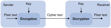
A key owner can distribute the public key in plain text on the network but must keep the private key in privacy. It is mathematically infeasible to calculate the private key even if an attacker knows the algorithm and the public key.
The security applications use the asymmetric key algorithms for the following purposes:
· Encryption and decryption—Any public key receiver can use the public key to encrypt information, but only the private key owner can decrypt the information.
· Digital signature—The key owner uses the private key to "sign" information to be sent, and the receiver decrypts the information with the sender's public key to verify information authenticity.
RSA, DSA, and ECDSA can all perform digital signature, but only RSA can perform encryption and decryption.
Asymmetric key algorithms enables secure key distribution on an insecure network, but the security strength of an asymmetric key algorithm still depends on key size as with any symmetric key algorithm.
FIPS compliance
The device supports the FIPS mode that complies with NIST FIPS 140-2 requirements. Support for features, commands, and parameters might differ in FIPS mode (see "Configuring FIPS") and non-FIPS mode.
Creating a local key pair
Configuration guidelines
When you create a local key pair, follow these guidelines:
· The key algorithm must be the same as required by the security application.
· The key modulus length must be appropriate (see Table 5). The longer the key modulus length, the higher the security, the longer the key generation time.
· If you do not assign the key pair a name, the system assigns the default name to the key pair and marks the key pair as default. You can also assign the default name to another key pair, but the system does not mark the key pair as default.
· The name of a key pair must be unique among all manually named key pairs that use the same key algorithm, but can be the same as a key pair that uses a different key algorithm. If a name conflict occurs, the system asks whether you want to overwrite the existing key pair.
· The key pairs are automatically saved and can survive system reboots.
Table 5 A comparison of different types of asymmetric key algorithms
|
Generated key pairs |
Modulus length |
|
|
RSA |
· In non-FIPS mode: ? One host key pair, if you specify a key pair name. ? One server key pair and one host key pair, if you do not specify a
key pair name. · In FIPS mode: One host key pair. NOTE: Only SSH 1.5 uses the RSA server key pair. |
·
In non-FIPS mode: 512 to 2048 bits, 1024 bits
by default. · In FIPS mode: 2048 bits. |
|
DSA |
One host key pair. |
·
In non-FIPS mode: 512 to 2048 bits, 1024 bits
by default. · In FIPS mode: 2048 bits. |
|
ECDSA |
One host key pair. |
192 bits. |
Configuration procedure
To create a local key pair:
|
Step |
Command |
Remarks |
|
1. Enter system view. |
system-view |
N/A |
|
2. Create local DSA or RSA key pairs. |
public-key local create { dsa | ecdsa | rsa } [ name key-name ] |
By default, no local key pair exists. |
Distributing a local host public key
You must distribute a local host public key to a peer device so the peer device can use the public key to encrypt information sent to the local device or authenticate the digital signature signed by the local device.
To distribute a local host public key:
1. Record the key or export the key to a file
2. Transfer the key, for example, by using FTP or TFTP
This section covers only the first task.
The following are the methods available for recording or exporting a local host public key:
· Exporting a host public key in a specific format to a file. Use this method if you can import public keys from a file on the peer device.
· Displaying a host public key in a specific format and saving it to a file. Use this method if you can import public keys from a file on the peer device.
· Displaying a host public key. Use this method if you must manually enter the key on the peer device.
Exporting a host public key in a specific format to a file
|
Step |
Command |
|
1. Enter system view. |
system-view |
|
2. Export a local host public key in a specific format to a file. |
· Export an RSA host public key: ? In non-FIPS mode: ? In FIPS mode: ·
Export a DSA host public key: |
Displaying a host public key in a specific format and saving it to a file
After you display a host public key in a specific format, save the key to a file and transfer the file to the peer device.
To display a local host public key in a specific format:
|
Step |
Command |
|
1. Enter system view. |
system-view |
|
2. Display local host public keys in a specific format. |
· Display RSA host public keys: ? In non-FIPS mode: ? In FIPS mode: ·
Display DSA host public keys: |
Displaying a host public key
Display a host public key and copy it to an unformatted file. You must literally enter the key on the peer device.
Perform the following tasks in any view:
|
Task |
Command |
|
Display local RSA public keys. |
display public-key local rsa public [ name key-name ] |
|
Display local DSA public keys. |
display public-key local dsa public [ name key-name ] |
|
|
NOTE: Do not distribute the RSA server public key serverkey (default) to a peer device. |
Destroying a local key pair
To avoid key compromise, destroy the local key pair and generate a new pair after any of the following conditions occurs:
· An intrusion event has occurred.
· The storage media of the device is replaced.
· The local certificate has expired.
To destroy a local key pair:
|
Step |
Command |
Remarks |
|
1. Enter system view. |
system-view |
N/A |
|
2. Destroy a local key pair. |
public-key local destroy { dsa | ecdsa | rsa } [ name key-name ] |
N/A |
Configuring a peer public key
To encrypt information sent to a peer device or authenticate the digital signature of the peer device, you must configure the public key of the peer device on the local device.
Table 6 Peer public key configuration methods
|
Method |
Prerequisites |
Remarks |
|
Import the peer public key from a public key file (recommended) |
3. Save the host public key in a file on the peer device. 4. Get the file from the peer device, for example, by using FTP or TFTP in binary mode. |
The system automatically converts the imported public key to a string in the Public Key Cryptography Standards (PKCS) format. |
|
Manually enter (type or copy) the peer public key |
Display and record the public key on the peer device.
If the peer device is an H3C device, use the display public-key local public command to display the public key. The format of the public key displayed in any other way might be incorrect. |
· If the key is not in the correct format, the system discards the key and displays an error message. If the key is valid, for example, the key displayed by the display public-key local public command, the system saves the key. · Always use the first method if you are not sure of the format of the recorded public key. |
For information about displaying or exporting host public keys, see "Distributing a local host public key."
Importing a peer host public key from a public key file
|
Step |
Command |
Remarks |
|
1. Enter system view. |
system-view |
N/A |
|
2. Import a peer host public key from a public key file. |
public-key peer keyname import sshkey filename |
By default, no peer host public key exists. |
Entering a peer public key
|
Step |
Command |
Remarks |
|
1. Enter system view. |
system-view |
N/A |
|
2. Specify a name for the peer public key and enter public key view. |
public-key peer keyname |
By default, no peer host public key exists. |
|
3. Type or copy the key. |
N/A |
You can use spaces and carriage returns, but the system does not save them. |
|
4. Return to system view. |
peer-public-key end |
When you exit public key view, the system automatically saves the public key. |
Displaying and maintaining public keys
Execute display commands in any view.
|
Task |
Command |
|
Display local public keys. |
display public-key local { dsa | ecdsa | rsa } public [ name key-name ] |
|
Display peer public keys. |
display public-key peer [ brief | name publickey-name ] [ name key-name ] |
Examples of public key management
Example for entering a peer public key
Network requirements
As shown in Figure 15, to prevent illegal access, Device B authenticates Device A through a digital signature. Before configuring authentication parameters on Device B, configure the public key of Device A on Device B.
· Configure Device B to use the asymmetric key algorithm of RSA to authenticate Device A.
· Manually specify the host public key of Device A on Device B.
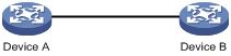
Configuration procedure
1. Configure Device A:
# Create local RSA key pairs with default names on Device A, and use the default modulus length 1024 bits.
<DeviceA> system-view
[DeviceA] public-key local create rsa
The range of public key modulus is (512 ~ 2048).
If the key modulus is greater than 512, it will take a few minutes.
Press CTRL+C to abort.
Input the modulus length [default = 1024]:
Generating Keys...
.................++++++
......................................++++++
.....++++++++
..............++++++++
Create the key pair successfully.
# Display all local RSA public keys.
[DeviceA] display public-key local rsa public
=============================================
Key name: hostkey (default)
Key type: RSA
Time when key pair created: 16:48:31 2011/05/12
Key code:
30819F300D06092A864886F70D010101050003818D0030818902818100DA3B90F59237347B
8D41B58F8143512880139EC9111BFD31EB84B6B7C7A1470027AC8F04A827B30C2CAF79242E
45FDFF51A9C7E917DB818D54CB7AEF538AB261557524A7441D288EC54A5D31EFAE4F681257
6D7796490AF87A8C78F4A7E31F0793D8BA06FB95D54EBB9F94EB1F2D561BF66EA27DFD4788
CB47440AF6BB25ACA50203010001
=============================================
Key name: serverkey (default)
Key type: RSA
Time when key pair created: 16:48:31 2011/05/12
Key code:
307C300D06092A864886F70D0101010500036B003068026100C9451A80F7F0A9BA1A90C7BC
1C02522D194A2B19F19A75D9EF02219068BD7FD90FCC2AF3634EEB9FA060478DD0A1A49ACE
E1362A4371549ECD85BA04DEE4D6BB8BE53B6AED7F1401EE88733CA3C4CED391BAE633028A
AC41C80A15953FB22AA30203010001
2. Configure Device B:
# Enter the host public key of Device A in public key view. The key must be literally the same as displayed on Device A.
<DeviceB> system-view
[DeviceB] public-key peer devicea
Enter public key view. Return to system view with "peer-public-key end" command.
[DeviceB-pkey-public-key-devicea]30819F300D06092A864886F70D010101050003818D003081890
2818100DA3B90F59237347B
[DeviceB-pkey-public-key-devicea]8D41B58F8143512880139EC9111BFD31EB84B6B7C7A1470027A
C8F04A827B30C2CAF79242E
[DeviceB-pkey-public-key-devicea]45FDFF51A9C7E917DB818D54CB7AEF538AB261557524A7441D2
88EC54A5D31EFAE4F681257
[DeviceB-pkey-public-key-devicea]6D7796490AF87A8C78F4A7E31F0793D8BA06FB95D54EBB9F94E
B1F2D561BF66EA27DFD4788
[DeviceB-pkey-public-key-devicea]CB47440AF6BB25ACA50203010001
# Save the public key and return to system view.
[DeviceB-pkey-public-key-devicea] peer-public-key end
Verifying the configuration
# Verify that the key is the same as on Device A.
[DeviceB] display public-key peer name devicea
=============================================
Key name: devicea
Key type: RSA
Key modulus: 1024
Key code:
30819F300D06092A864886F70D010101050003818D0030818902818100DA3B90F59237347B
8D41B58F8143512880139EC9111BFD31EB84B6B7C7A1470027AC8F04A827B30C2CAF79242E
45FDFF51A9C7E917DB818D54CB7AEF538AB261557524A7441D288EC54A5D31EFAE4F681257
6D7796490AF87A8C78F4A7E31F0793D8BA06FB95D54EBB9F94EB1F2D561BF66EA27DFD4788
CB47440AF6BB25ACA50203010001
Example for importing a public key from a public key file
Network requirements
As shown in Figure 16, Device B authenticates Device A through a digital signature. Before configuring authentication parameters on Device B, configure the public key of Device A on Device B.
· Configure Device B to use the asymmetric key algorithm of RSA to authenticate Device A.
· Import the host public key of Device A from the public key file to Device B.
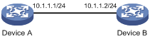
Configuration procedure
1. Configure Device A:
# Create local RSA key pairs with default names on Device A, and use the default modulus length 1024 bits.
<DeviceA> system-view
[DeviceA] public-key local create rsa
The range of public key modulus is (512 ~ 2048).
If the key modulus is greater than 512, it will take a few minutes.
Press CTRL+C to abort.
Input the modulus length [default = 1024]:
Generating Keys...
.................++++++
......................................++++++
.....++++++++
..............++++++++
Create the key pair successfully.
# Display all local RSA public keys.
[DeviceA] display public-key local rsa public
=============================================
Key name: hostkey (default)
Key type: RSA
Time when key pair created: 16:48:31 2011/05/12
Key code:
30819F300D06092A864886F70D010101050003818D0030818902818100DA3B90F59237347B
8D41B58F8143512880139EC9111BFD31EB84B6B7C7A1470027AC8F04A827B30C2CAF79242E
45FDFF51A9C7E917DB818D54CB7AEF538AB261557524A7441D288EC54A5D31EFAE4F681257
6D7796490AF87A8C78F4A7E31F0793D8BA06FB95D54EBB9F94EB1F2D561BF66EA27DFD4788
CB47440AF6BB25ACA50203010001
=============================================
Key name: serverkey (default)
Key type: RSA
Time when key pair created: 16:48:31 2011/05/12
Key code:
307C300D06092A864886F70D0101010500036B003068026100C9451A80F7F0A9BA1A90C7BC
1C02522D194A2B19F19A75D9EF02219068BD7FD90FCC2AF3634EEB9FA060478DD0A1A49ACE
E1362A4371549ECD85BA04DEE4D6BB8BE53B6AED7F1401EE88733CA3C4CED391BAE633028A
AC41C80A15953FB22AA30203010001
# Export the RSA host public key to the file devicea.pub.
[DeviceA] public-key local export rsa ssh2 devicea.pub
[DeviceA] quit
# Enable the FTP server function, create an FTP user with the username ftp and password 123, and configure the FTP user role as network-admin.
[DeviceA] ftp server enable
[DeviceA] local-user ftp
[DeviceA-luser-manage-ftp] password simple 123
[DeviceA-luser-manage-ftp] service-type ftp
[DeviceA-luser-manage-ftp] authorization-attribute user-role network-admin
[DeviceA-luser-manage-ftp] quit
2. Configure Device B:
# Use FTP in binary mode to get the public key file devicea.pub from Device A.
<DeviceB> ftp 10.1.1.1
Connected to 10.1.1.1 (10.1.1.1).
220 FTP service ready.
User(10.1.1.1:(none)):ftp
331 Password required for ftp.
Password:
230 User logged in.
Remote system type is UNIX.
Using binary mode to transfer files.
ftp> binary
200 TYPE is now 8-bit binary
ftp> get devicea.pub
227 Entering Passive Mode (10,1,1,1,118,252)
150 Accepted data connection
226 File successfully transferred
301 bytes received in 0.003 seconds (98.0 kbyte/s)
ftp> quit
221-Goodbye. You uploaded 0 and downloaded 1 kbytes.
221 Logout.
# Import the host public key from the key file devicea.pub.
<DeviceB> system-view
[DeviceB] public-key peer devicea import sshkey devicea.pub
Verifying the configuration
# Verify that the host public key is the same as it is on Device A.
[DeviceB] display public-key peer name devicea
=============================================
Key name: devicea
Key type: RSA
Key modulus: 1024
Key code:
30819F300D06092A864886F70D010101050003818D0030818902818100DA3B90F59237347B
8D41B58F8143512880139EC9111BFD31EB84B6B7C7A1470027AC8F04A827B30C2CAF79242E
45FDFF51A9C7E917DB818D54CB7AEF538AB261557524A7441D288EC54A5D31EFAE4F681257
6D7796490AF87A8C78F4A7E31F0793D8BA06FB95D54EBB9F94EB1F2D561BF66EA27DFD4788
CB47440AF6BB25ACA50203010001
Configuring PKI
Overview
Public Key Infrastructure (PKI) is an asymmetric key infrastructure to encrypt and decrypt data for securing network services. Data encrypted with the public key can be decrypted only with the private key. Likewise, data encrypted with the private key can be decrypted only with the public key.
PKI uses digital certificates to distribute and employ public keys, and provides network communication and e-commerce with security services such as user authentication, data confidentiality, and data integrity.
H3C's PKI system provides certificate management for IPsec and SSL.
PKI terminology
Digital certificate
A digital certificate is an electronic document signed by a CA that binds a public key with the identity of its owner.
A digital certificate includes the following information:
· Issuer name (the name of the CA that issued the certificate).
· Subject name (name of the individual or group to which the certificate is issued).
· Identity information of the subject.
· Subject's public key.
· Signature of the CA.
· Period of validity.
A digital certificate must comply with the international standards of ITU-T X.509, of which X.509 v3 is the most commonly used.
This chapter covers the following types of certificates:
· CA certificate—Certificate of a CA. Multiple CAs in a PKI system form a CA tree, with the root CA at the top. The root CA generates a self-signed certificate, and each lower level CA holds a CA certificate issued by the CA immediately above it. The chain of these certificates forms a chain of trust.
· Registration authority (RA) certificate—Certificate issued by a CA to an RA. RAs act as proxies for CAs to process enrollment requests in a PKI system.
· Local certificate—Digital certificate issued by a CA to a PKI entity, which contains the entity's public key.
· Peer certificate—Digital certificate of a peer, which contains the peer's public key and is signed by a CA.
Certificate revocation list
A certificate revocation list (CRL) is a list of serial numbers for certificates that have been revoked. A CRL is created and signed by the CA that originally issued the certificates.
The CA publishes CRLs periodically to revoke certificates. Entities that are associated with the revoked certificates should not be trusted.
The CA must revoke a certificate when any of the following conditions occurs:
· The certificate subject name is changed.
· The private key is compromised.
· The association between the subject and CA is changed. For example, when an employee terminates employment with an organization.
CA policy
A CA policy is a set of criteria that a CA follows to process certificate requests, to issue and revoke certificates, and to publish CRLs. Typically, a CA advertises its policy in a certification practice statement (CPS). You can obtain a CA policy through out-of-band means such as phone, disk, and email. Make sure you understand the CA policy before you select a trusted CA for certificate request because different CAs might use different policies.
PKI architecture
A PKI system consists of PKI entities, CAs, RAs and a certificate/CRL repository, as shown in Figure 17.
Figure 17 PKI architecture
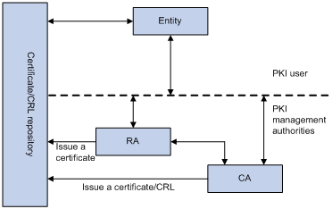
· PKI entity—An end user using PKI certificates. The PKI entity can be an operator, an organization, a device like a router or a switch, or a process running on a computer. PKI entities use SCEP to communicate with the CA or RA.
· CA—Certification authority that grants and manages certificates. A CA issues certificates, defines the certificate validity periods, and revokes certificates by publishing CRLs.
· RA—Registration authority, which offloads the CA by processing enrollment requests. The RA accepts certificate requests, verifies user identity, and determines whether to ask the CA to issue certificates.
The RA is optional in a PKI system. In cases when the CA operates over a wide geographical area or when there is security concern over exposing the CA to direct network access, it is advisable to delegate some of the tasks to an RA and leave the CA to concentrate on its primary tasks of signing certificates and CRLs.
· Certificate/CRL repository—A certificate distribution point that stores certificates and CRLs, and distributes these certificates and CRLs to PKI entities. It also provides the query function. A PKI repository can be a directory server using the LDAP or HTTP protocol, of which LDAP is commonly used.
PKI operation
The following workflow describes how a PKI entity requests a local certificate from a CA that has RAs:
1. A PKI entity submits a certificate request to the RA.
2. The RA verifies the identity of the entity and sends a digital signature containing the identity information and the public key to the CA.
3. The CA verifies the digital signature, approves the request, and issues a certificate.
4. After receiving the certificate from the CA, the RA sends the certificate to the certificate repositories and notifies the PKI entity that the certificate has been issued.
5. The entity obtains the certificate from the certificate repository.
PKI applications
The PKI technology can meet security requirements of online transactions. As an infrastructure, PKI has a wide range of applications. Here are some application examples.
· VPN—A VPN is a private data communication network built on the public communication infrastructure. A VPN can use network layer security protocols (for example, IPsec) in conjunction with PKI-based encryption and digital signature technologies for confidentiality.
· Secure emails—PKI can address the email requirements for confidentiality, integrity, authentication, and non-repudiation. A common secure email protocol is Secure/Multipurpose Internet Mail Extensions (S/MIME), which is based on PKI and allows for transfer of encrypted mails with signature.
Support for MPLS L3VPN
An enterprise might have multiple branches in different VPNs. PKI support for MPLS L3VPN is required if users in different VPNs request certificates from the CA server in the headquarters VPN.
As shown in Figure 18, the PKI entity in VPN 1 requests a certificate from the CA server in VPN 3 in the following workflow:
1. The PKI entity submits a certificate request to the CA server.
2. The PE device that connects to the PKI entity transmits the request to the CA server through MPLS L3VPN.
3. The CA server verifies the request and issues the certificate.
4. The PE device that connects to the CA server transmits the certificate to the PKI entity.
For information about MPLS L3VPN, see MPLS Configuration Guide.
Figure 18 PKI support for MPLS L3VPN
Feature and software version compatibility
The PKI feature is available in Release 1138P01 and later versions.
FIPS compliance
The device supports the FIPS mode that complies with NIST FIPS 140-2 requirements. Support for features, commands, and parameters might differ in FIPS mode (see "Configuring FIPS") and non-FIPS mode.
PKI configuration task list
|
Tasks at a glance |
|
|
(Required.) Configuring a PKI entity |
|
|
(Required.) Configuring a PKI domain |
|
|
(Required.) Requesting a certificate: |
|
|
(Optional.) Aborting a certificate request |
|
|
(Optional.) Obtaining certificates |
|
|
(Optional.) Verifying PKI certificates |
|
|
(Optional.) Specifying the storage path for the certificates and CRLs |
|
|
(Optional.) Exporting certificates |
|
|
(Optional.) Removing a certificate |
|
|
(Optional.) Configuring a certificate-based access control policy |
Configuring a PKI entity
A certificate applicant uses an entity to provide its identity information to a CA. A valid PKI entity must include one or more of following identity categories:
· Distinguished name (DN) of the entity, which further includes the common name, county code, locality, organization, unit in the organization, and state. If you configure the DN for an entity, a common name is required.
· FQDN of the entity.
· IP address of the entity.
Whether the categories are required or optional depends on the CA policy. Follow the CA policy to configure the entity settings. For example, if the CA policy requires the entity DN, but you configure only the IP address, the CA rejects the certificate request from the entity.
The SCEP add-on on the Windows 2000 CA server has restrictions on the data length of a certificate request. If a request from a PKI entity exceeds the data length limit, the CA server does not respond to the certificate request. In this case, you can use an out-of-band means to submit the request. Other types of CA servers, such as RSA servers and OpenCA servers, do not have such restrictions.
To configure a PKI entity:
|
Step |
Command |
Remarks |
|
1. Enter system view. |
system-view |
N/A |
|
2. Create a PKI entity and enter its view. |
pki entity entity-name |
By default, no PKI entities exist. To create multiple PKI entities, repeat this step. |
|
3. Set a common name for the entity. |
common-name common-name-sting |
By default, the common name is not set. |
|
4. Set the country code of the entity. |
country country-code-string |
By default, the country code is not set. |
|
5. Set the locality of the entity. |
locality locality-name |
By default, the locality is not set. |
|
6. Set the organization of the entity. |
organization org-name |
By default, the organization is not set. |
|
7. Set the unit of the entity in the organization. |
organization-unit org-unit-name |
By default, the unit is not set. |
|
8. Set the state where the entity resides. |
state state-name |
By default, the state is not set. |
|
9. Set the FQDN of the entity. |
fqdn fqdn-name-string |
By default, the FQDN is not set. |
|
10. Configure the IP address of the entity. |
ip { ip-address | interface interface-type interface-number } |
By default, the IP address is not configured. |
Configuring a PKI domain
A PKI domain contains enrollment information for a PKI entity. It is locally significant and is intended only for reference by other applications like IKE and SSL.
To configure a PKI domain:
|
Step |
Command |
Remarks |
|
1. Enter system view. |
system-view |
N/A |
|
2. Create a PKI domain and enter its view. |
pki domain domain-name |
By default, no PKI domains exist. |
|
3. Specify the trusted CA. |
ca identifier name |
By default, no trusted CA is specified. To obtain a CA certificate, the trusted CA name must be provided. The trusted CA name uniquely identifies the CA to be used if multiple CAs exist on the same CA server. The CA server's URL is specified by using the certificate request url command. |
|
4. Specify the PKI entity name. |
certificate request entity entity-name |
By default, no entity is specified. |
|
5. Specify the type of certificate request reception authority. |
certificate request from { ca | ra } |
By default, no authority type is specified. |
|
6. Specify the certificate request URL. |
certificate request url url-string [ vpn-instance vpn-instance-name ] |
By default, the certificate request URL is not specified. Do not configure this command when you request a certificate in offline mode. |
|
7. (Optional.) Set the SCEP polling interval and maximum number of polling attempts. |
certificate request polling { count count | interval minutes } |
By default, the switch polls the CA server for the certificate request status every 20 minutes. The maximum number of polling attempts is 50. |
|
8. (Optional.) Specify the LDAP server. |
ldap-server host hostname [ port port-number ] [ vpn-instance vpn-instance-name ] |
This task is required only when the CRL repository is an LDAP server and the URL of the CRL repository does not contain the host name of the LDAP server. By default, no LDAP server is specified. |
|
9. Enter a fingerprint to be matched against the fingerprint of the root CA certificate. |
·
In non-FIPS mode: ·
In FIPS mode: |
Before a PKI entity can enroll with a CA, it must authenticate the CA by obtaining the self-signed certificate of the CA and verifying the fingerprint of the CA certificate. If a fingerprint is not entered in the PKI domain, and if the CA certificate is imported or obtained through manual certificate request, you must verify the fingerprint that is displayed during authentication of the CA certificate. If the CA certificate is obtained through automatic certificate request, the certificate will be rejected if a fingerprint has not been entered. By default, no fingerprint is specified. |
|
10. Specify the key pair for certificate request. |
·
Specify an RSA key pair: ·
Specify a DSA key pair: |
By default, no key pair is specified. If the specified key pair does not exist, the PKI entity automatically creates the key pair before submitting a certificate request. For information about creating key pairs, see "Managing public keys" |
|
11. (Optional.) Specify the intended use for the certificate. |
usage { ike | ssl-client | ssl-server } * |
By default, the certificate can be used by all applications, including IKE, SSL clients, and SSL server. The extension options contained in an issued certificate depend on the CA policy, and they might be different from those specified in the PKI domain. |
|
12. (Optional.) Specify a source IP address for the PKI protocol packets. |
source ip { ip-address | interface {interface-type interface-number } |
This task is required if the CA policy requires that the CA server accept certificate requests from a specific IP address or subnet. By default, the source IP address of PKI protocol packets is the IP address of their outgoing interface. |
Requesting a certificate
To request a certificate, a PKI entity must provide its identity information and public key to a CA.
A certificate request can be submitted to a CA in offline or online mode.
· Offline mode—A certificate request is submitted by using an out-of-band method, such as phone, disk, or email. You can use this mode as required or if you fail to request a certificate in online mode.
To submit a certificate request in offline mode:
a. Use pki request-certificate domain pkcs10 to print the request information on the terminal or use pki request-certificate domain pkcs10 filename to save the request information to a local file.
b. Send the printed information or the saved file to the CA by using an out-of-band method to submit the request.
· Online mode—A certificate request can be automatically or manually submitted. This section describes the online request mode.
Configuration guidelines
The following guidelines apply to certificate request for an entity in a PKI domain:
· Make sure the device is time synchronized with the CA server. Otherwise, the certificate request might fail because the certificate is considered to be outside of the validity period. For information about how to configure the system time, see Fundamentals Configuration Guide.
· To request a new certificate for a PKI entity that already has a local certificate, perform the following steps:
a. Use the pki delete-certificate command to delete the existing local certificate.
b. Use the public-key local create to generate a new key pair. The new key pair will automatically overwrite the old key pair in the domain.
c. Submit a new certificate request.
· After a new certificate is obtained, do not use the public-key local create or public-key local destroy command to generate or destroy a key pair with the same name as the key pair in the local certificate. Otherwise, the existing local certificate becomes unavailable.
· A PKI domain can have local certificates using only one type of cryptographic algorithms (DSA or RSA). If DSA is used, a PKI domain can have only one local certificate. If RSA is used, a PKI domain can have one local certificate for signature, and one local certificate for encryption.
Configuring automatic certificate request
|
|
IMPORTANT: The device does not support automatic certificate rollover. To avoid service interruptions, you must manually submit a certificate renewal request before the current certificate expires. |
In auto request mode, a PKI entity automatically submits a certificate request to the CA when an application works with the PKI entity that does not have a local certificate. For example, when IKE negotiation uses a digital signature for identity authentication, but no local certificate is available, the entity automatically submits a certificate request. It saves the certificate locally after obtaining it from the CA.
A CA certificate must be present before you request a local certificate. If no CA certificate exists in the PKI domain, the PKI entity automatically obtains a CA certificate before sending a certificate request.
To configure automatic certificate request:
|
Step |
Command |
Remarks |
|
1. Enter system view. |
system-view |
N/A |
|
2. Enter PKI domain view. |
pki domain domain-name |
N/A |
|
3. Set the certificate request mode to auto. |
certificate request mode auto [ password { cipher | simple } password ] |
By default, the manual request mode applies. In auto request mode, set a password for certificate revocation as required by the CA policy. |
Manually requesting a certificate
Before you manually submit a certificate request, make sure the CA certificate exists and a key pair is specified for the PKI domain:
· The CA certificate is used to verify the authenticity and validity of the obtained local certificate.
· The key pair is used for certificate request. Upon receiving the public key and the identity information, the CA signs and issues a certificate.
After the CA issues the certificate, the device obtains and saves it locally.
To manually request a certificate:
|
Step |
Command |
Remarks |
|
1. Enter system view. |
system-view |
N/A |
|
2. Enter PKI domain view. |
pki domain domain-name |
N/A |
|
3. Set the certificate request mode to manual. |
certificate request mode manual |
By default, the manual request mode applies. |
|
4. Return to system view. |
quit |
N/A |
|
5. Obtain the CA certificate. |
See "Obtaining certificates." |
N/A |
|
6. Submit a certificate request or generate a certificate request in PKCS#10 format. |
pki request-certificate domain domain-name [ password password ] [ pkcs10 [ filename filename ] ] |
This command is not saved in the configuration file. This command triggers the PKI entity to automatically generate a key pair if the key pair specified in the PKI domain does not exist. The name, algorithm, and length of the key pair are configured in the PKI domain. |
Aborting a certificate request
Before the CA issues a certificate, you can abort a certificate request and change its parameters, such as the common name, country code, or FQDN. You can use the display pki certificate request-status command to display the status of a certificate request.
Alternatively, you also can remove a PKI domain to abort the associated certificate request.
To abort a certificate request:
|
Step |
Command |
Remarks |
|
1. Enter system view. |
system-view |
N/A |
|
2. Abort a certificate request. |
pki abort-certificate-request domain domain-name |
This command is not saved in the configuration file. |
Obtaining certificates
You can obtain the CA certificate, local certificates, and peer certificates related to a PKI domain from a CA and save them locally for higher lookup efficiency. To do so, use either the offline mode or the online mode:
· In offline mode, obtain the certificates by an out-of-band means like FTP, disk, or email, and then import them locally. Use this mode when the CRL repository is not specified, the CA server does not support SCEP, or the CA server generates the key pair for the certificates.
· In online mode, you can obtain the CA certificate through SCEP and obtain local certificates or peer certificates through LDAP.
Configuration prerequisites
To obtain local or peer certificates in online mode, specify the LDAP server for the PKI domain.
To import local or peer certificates in offline mode, perform the following tasks:
· Use FTP or TFTP to upload the certificate files to the storage media of the device. If FTP or TFTP is not available, display and copy the contents of a certificate to a file on the device. Make sure the certificate is in PEM format because only certificates in PEM format can be imported.
· To import a certificate, a CA certificate chain must exist in the PKI domain, or be contained in the certificate. If the CA certificate chain is not available, obtain it before importing the certificate.
Configuration guidelines
· To import a local certificate containing an encrypted key pair, you must provide the challenge password. Contact the CA administrator to obtain the password.
· If a CA certificate already exists locally, you cannot obtain it again in online mode. If you want to obtain a new one, use the pki delete-certificate command to remove the existing CA certificate and local certificates first.
· If local or peer certificates already exist, you can obtain new local or peer certificates to overwrite the existing ones. If RSA is used, a PKI domain can have two local certificates, one for signature and the other for encryption.
· If CRL checking is enabled, obtaining a certificate triggers CRL checking. If the certificate to be obtained has been revoked, the certificate cannot be obtained.
· The device compares the validity period of a certificate with the local system time to determine whether the certificate is valid. Make sure the system time of the device is synchronized with the CA server.
Configuration procedure
To obtain certificates:
|
Step |
Command |
Remarks |
|
1. Enter system view. |
system-view |
N/A |
|
2. Obtain certificates. |
·
Import certificates in offline mode: ·
Obtain certificates in online mode: |
The pki retrieve-certificate command is not saved in the configuration file. |
Verifying PKI certificates
A certificate is automatically verified when it is requested, obtained, or used by an application. If the certificate expires, if it is not issued by a trusted CA, or if it is revoked, the certificate cannot be used.
You can also manually verify a certificate. If it has been revoked, the certificate cannot be requested or obtained.
Verifying certificates with CRL checking
CRL checking checks whether a certificate is in the CRL. If it is, the certificate has been revoked and its home entity is not trusted.
To use CRL checking, a CRL must be obtained from a CRL repository. The device selects a CRL repository in the following order:
1. CRL repository specified in the PKI domain by using this command.
2. CRL repository in the certificate that is being verified.
3. CRL repository in the CA certificate or CRL repository in the upper-level CA certificate if the CA certificate is the certificate being verified.
If no CRL repository is found after the selection process, the device obtains the CRL through SCEP. In this scenario, the CA certificate and the local certificates must have been obtained.
To verify certificates with CRL checking:
|
Step |
Command |
Remarks |
|
1. Enter system view. |
system-view |
N/A |
|
2. Enter PKI domain view. |
pki domain domain-name |
N/A |
|
3. (Optional.) Specify the URL of the CRL repository. |
crl url url-string [ vpn-instance vpn-instance-name ] |
By default, the URL of the CRL repository is not specified. |
|
4. Enable CRL checking. |
crl check enable |
By default, CRL checking is enabled. |
|
5. Return to system view. |
quit |
N/A |
|
6. Obtain the CA certificate. |
See "Obtaining certificates." |
N/A |
|
7. (Optional.) Obtain the CRL and save it locally. |
pki retrieve-crl domain domain-name |
The newly obtained CRL overwrites the old one, if any. The obtained CRL must be issued by a CA certificate in the CA certificate chain in the current domain. |
|
8. Verify the validity of the certificates. |
pki validate-certificate domain domain-name { ca | local } |
N/A |
Verifying certificates without CRL checking
|
Step |
Command |
Remarks |
|
1. Enter system view. |
system-view |
N/A |
|
2. Enter PKI domain view. |
pki domain domain-name |
N/A |
|
3. Disable CRL checking. |
undo crl check enable |
By default, CRL checking is enabled. |
|
4. Return to system view. |
quit |
N/A |
|
5. Obtain the CA certificate. |
See "Obtaining certificates." |
N/A |
|
6. Verify the validity of the certificates. |
pki validate-certificate domain domain-name { ca | local } |
This command is not saved in the configuration file. |
Specifying the storage path for the certificates and CRLs
|
|
CAUTION: If you change the storage path, save the configuration before you reboot or shut down the device to avoid loss of the certificates or the CRLs. |
The device has a default storage path for certificates and CRLs. You can change the storage path and specify different paths for the certificates and CRLs.
After you change the storage path for certificates or CRLs, the certificate files (with the .cer or .p12 extension) and CRL files (with the .crl extension) in the original path are moved to the new path.
To specify the storage path for the certificates and CRLs:
|
Task |
Command |
Remarks |
|
Specify the storage path for certificates and CRLs. |
pki storage { certificates | crls } dir-path |
By default, the device stores certificates and CRLs in the PKI directory on the storage media of the device. |
Exporting certificates
|
|
IMPORTANT: To export all certificates in the PKCS12 format, the PKI domain must have a minimum of one local certificate. Otherwise, the certificates in the PKI domain cannot be exported. |
You can export the CA certificate and the local certificates in a PKI domain to certificate files. The exported certificate files can then be imported back to the device or other PKI applications.
When you export a local certificate with the RSA key pair, the name of the target file might not be the same as specified in the command. It depends on the purpose of the key pair of the certificate.
To export certificates:
|
Step |
Command |
Remarks |
|
1. Enter system view. |
system-view |
N/A |
|
2. Export certificates. |
·
Export certificates in DER format: ·
Export certificates in PKCS12 format: ·
Export certificates in PEM format: |
If you do not specify a file name when you export a certificate in PEM format, the certificate is displayed on the terminal. |
Removing a certificate
You can remove the CA certificate, local certificate, or peer certificates in a PKI domain. After you remove the CA certificate, the system automatically removes the local certificates, peer certificates, and CRLs in the domain.
You can remove a local certificate and request a new one when the local certificate is about to expire or the certificate's private key is compromised. To remove a local certificate and request a new certificate, perform the following tasks:
1. Remove the local certificate.
2. Use the public-key local destroy command to destroy the existing local key pair.
3. Use the public-key local create command to generate a new key pair.
4. Request a new certificate.
To remove a certificate:
|
Step |
Command |
Remarks |
|
1. Enter system view. |
system-view |
N/A |
|
2. Remove a certificate. |
pki delete-certificate domain domain-name { ca | local | peer [ serial serial-num ] } |
If you use the peer keyword without specifying a serial number, the command removes all peer certificates. |
Configuring a certificate-based access control policy
Certificate-based access control policies allow you to authorize access to a device (for example, an HTTPS server) based on the attributes of an authenticated client's certificate.
A certificate-based access control policy is a set of access control rules (permit or deny statements), each associated with a certificate attribute group. A certificate attribute group contains multiple attribute rules, each defining a matching criterion for an attribute in the certificate issuer name, subject name, or alternative subject name field.
If a certificate matches all attribute rules in a certificate attribute group associated with an access control rule, the system determines that the certificate matches the access control rule. In this scenario, the match process stops, and the system performs the access control action defined in the access control rule.
The following conditions describe how a certificate-based access control policy verifies the validity of a certificate:
· If a certificate matches a permit statement, the certificate passes the verification.
· If a certificate matches a deny statement or does not match any statements in the policy, the certificate is regarded invalid.
· If a statement is associated with a non-existing attribute group, or the attribute group does not have attribute rules, the certificate matches the statement.
· If the certificate-based access control policy referenced by a security application (for example, HTTPS) does not exist, all certificates in the application pass the verification.
To configure a certificate-based access control policy:
|
Step |
Command |
Remarks |
|
1. Enter system view. |
system-view |
N/A |
|
2. Create a certificate attribute group and enter its view. |
pki certificate attribute-group group-name |
By default, no certificate attribute groups exist. |
|
3. (Optional.) Configure an attribute rule for issuer name, subject name, or alternative subject name. |
attribute id { alt-subject-name { fqdn | ip } | { issuer-name | subject-name } { dn | fqdn | ip } } { ctn | equ | nctn | nequ} attribute-value |
By default, not attribute rules are configured. |
|
4. Return to system view. |
quit |
N/A |
|
5. Create a certificate-based access control policy and enter its view. |
pki certificate access-control-policy policy-name |
By default, no certificate-based access control policy exists. |
|
6. Create a certificate access control rule. |
rule [ id ] { deny | permit } group-name |
By default, no certificate access control rules are configured, and all certificates can pass the verification. You can create multiple access control rules are for a certificate-based access control policy. |
Displaying and maintaining PKI
Execute display commands in any view.
|
Task |
Command |
|
Display the contents of a certificate. |
display pki certificate domain domain-name { ca | local | peer [ serial serial-num ] } |
|
Display certificate request status. |
display pki certificate request-status [ domain domain-name ] |
|
Display locally stored CRLs in a PKI domain. |
display pki crl domain domain-name |
|
Display certificate attribute group information. |
display pki certificate attribute-group [ group-name ] |
|
Display certificate-based access control policy information. |
display pki certificate access-control-policy [ policy-name ] |
PKI configuration examples
You can use different software applications, such as Windows server, RSA Keon, and OpenCA, to act as the CA server.
If you use Windows server or OpenCA, you must install the SCEP add-on for Windows server or enable SCEP for OpenCA. In either case, when you configure a PKI domain, you must use the certificate request from ra command to specify the RA to accept certificate requests.
If you use RSA Keon, the SCEP add-on is not required. When you configure a PKI domain, you must use the certificate request from ca command to specify the CA to accept certificate requests.
Requesting a certificate from an RSA Keon CA server
Network requirements
Configure the PKI entity (the device) to request a local certificate from the CA server.
Figure 19 Network diagram
Configuring the RSA Keon CA server
1. Create a CA server named myca:
In this example, you must configure these basic attributes on the CA server:
? Nickname—Name of the trusted CA.
? Subject DN—DN attributes of the CA, including the common name (CN), organization unit (OU), organization (O), and country (C).
You can use the default values for other attributes.
2. Configure extended attributes:
Configure parameters in the Jurisdiction Configuration section on the management page of the CA server:
? Select the correct extension profiles.
? Enable the SCEP autovetting function to enable the CA server to automatically approve certificate requests without manual intervention.
? Specify the IP address list for SCEP autovetting.
Configuring the device
1. Synchronize the system time of the device with the CA server for the device to correctly request certificates or obtain CRLs. (Details not shown.)
2. Create an entity named aaa and set the common name to Device.
<Device> system-view
[Device] pki entity aaa
[Device-pki-entity-aaa] common-name Device
[Device-pki-entity-aaa] quit
# Create a PKI domain named torsa and enter its view.
[Device] pki domain torsa
# Specify the name of the trusted CA as myca.
[Device-pki-domain-torsa] ca identifier myca
# Configure the URL of the CA server. The URL format is http://host:port/Issuing Jurisdiction ID, where Issuing Jurisdiction ID is a hexadecimal string generated on the CA server.
# Specify the CA for accepting certificate requests.
[Device-pki-domain-torsa] certificate request from ca
# Specify the PKI entity name as aaa.
[Device-pki-domain-torsa] certificate request entity aaa
# Specify the URL of the CRL repository.
[Device-pki-domain-torsa] crl url ldap://1.1.2.22:389/CN=myca
# Specify the RSA key pair with the purpose general, the name abc, and the length 1024 bits.
[Device-pki-domain-torsa] public-key rsa general name abc length 1024
[Device-pki-domain-torsa] quit
4. Generate a local RSA key pair.
[Device] public-key local create rsa name abc
The range of public key size is (512 ~ 2048).
If the key modulus is greater than 512,it will take a few minutes.
Press CTRL+C to abort.
Input the modulus length [default = 1024]:
Generating Keys...
..........................++++++
.....................................++++++
Create the key pair successfully.
5. Request a local certificate:
# Obtain the CA certificate and save it locally.
[Device] pki retrieve-certificate domain torsa ca
The trusted CA's finger print is:
MD5 fingerprint:EDE9 0394 A273 B61A F1B3 0072 A0B1 F9AB
SHA1 fingerprint: 77F9 A077 2FB8 088C 550B A33C 2410 D354 23B2 73A8
Is the finger print correct?(Y/N):y
Retrieved the certificates successfully.
# Submit a certificate request manually. You must specify a password for certificate revocation when an RSA Keon CA server is used.
[Device] pki request-certificate domain torsa password 1111
Start to request the general certificate ...
……
Certificate requested successfully.
Verifying the configuration
# Display information about the local certificate in PKI domain torsa.
[Device] display pki certificate domain torsa local
Certificate:
Data:
Version: 3 (0x2)
Serial Number:
15:79:75:ec:d2:33:af:5e:46:35:83:bc:bd:6e:e3:b8
Signature Algorithm: sha1WithRSAEncryption
Issuer: CN=myca
Validity
Not Before: Jan 6 03:10:58 2013 GMT
Not After : Jan 6 03:10:58 2014 GMT
Subject: CN=Device
Subject Public Key Info:
Public Key Algorithm: rsaEncryption
Public-Key: (1024 bit)
Modulus:
00:ab:45:64:a8:6c:10:70:3b:b9:46:34:8d:eb:1a:
a1:b3:64:b2:37:27:37:9d:15:bd:1a:69:1d:22:0f:
3a:5a:64:0c:8f:93:e5:f0:70:67:dc:cd:c1:6f:7a:
0c:b1:57:48:55:81:35:d7:36:d5:3c:37:1f:ce:16:
7e:f8:18:30:f6:6b:00:d6:50:48:23:5c:8c:05:30:
6f:35:04:37:1a:95:56:96:21:95:85:53:6f:f2:5a:
dc:f8:ec:42:4a:6d:5c:c8:43:08:bb:f1:f7:46:d5:
f1:9c:22:be:f3:1b:37:73:44:f5:2d:2c:5e:8f:40:
3e:36:36:0d:c8:33:90:f3:9b
Exponent: 65537 (0x10001)
X509v3 extensions:
X509v3 CRL Distribution Points:
Full Name:
DirName: CN = myca
Signature Algorithm: sha1WithRSAEncryption
b0:9d:d9:ac:a0:9b:83:99:bf:9d:0a:ca:12:99:58:60:d8:aa:
73:54:61:4b:a2:4c:09:bb:9f:f9:70:c7:f8:81:82:f5:6c:af:
25:64:a5:99:d1:f6:ec:4f:22:e8:6a:96:58:6c:c9:47:46:8c:
f1:ba:89:b8:af:fa:63:c6:c9:77:10:45:0d:8f:a6:7f:b9:e8:
25:90:4a:8e:c6:cc:b8:1a:f8:e0:bc:17:e0:6a:11:ae:e7:36:
87:c4:b0:49:83:1c:79:ce:e2:a3:4b:15:40:dd:fe:e0:35:52:
ed:6d:83:31:2c:c2:de:7c:e0:a7:92:61:bc:03:ab:40:bd:69:
1b:f5
To display detailed information about the CA certificate, use the display pki certificate domain command.
Requesting a certificate from a Windows Server 2003 CA server
Network requirements
Configure the PKI entity (the device) to request a local certificate from a Windows Server 2003 CA server.
Figure 20 Network diagram
Configuring the Windows Server 2003 CA server
1. Install the certificate service component:
a. Select Control Panel > Add or Remove Programs from the start menu.
b. Select Add/Remove Windows Components > Certificate Services.
c. Click Next to begin the installation.
d. Set the CA name. In this example, set the CA name to myca.
2. Install the SCEP add-on:
By default, Windows Server 2003 does not support SCEP. You must install the SCEP add-on on the server for a PKI entity to register and obtain a certificate from the server. After the SCEP add-on installation is complete, you will see a URL. Specify this URL as the certificate request URL on the device.
3. Modify the certificate service attributes:
a. Select Control Panel > Administrative Tools > Certificate Authority from the start menu.
If the certificate service component and SCEP add-on have been installed successfully, there should be two certificates issued by the CA to the RA.
b. Right-click the CA server in the navigation tree and select Properties > Policy Module.
c. Click Properties and then select Follow the settings in the certificate template, if applicable. Otherwise, automatically issue the certificate.
4. Modify the Internet information services attributes:
a. Select Control Panel > Administrative Tools > Internet Information Services (IIS) Manager from the start menu.
b. Select Web Sites from the navigation tree.
c. Right-click Default Web Site and select Properties > Home Directory.
d. Specify the path for certificate service in the Local path box.
e. Specify a unique port number for the default website to avoid conflict with existing services. In this example, port 8080 is used.
Configuring the device
1. Synchronize the device's system time with the CA server for the device to correctly request certificates. (Details not shown.)
2. Create an entity named aaa and set the common name to test.
<Device> system-view
[Device] pki entity aaa
[Device-pki-entity-aaa] common-name test
[Device-pki-entity-aaa] quit
3. Configure a PKI domain:
# Create a PKI domain named winserver and enter its view.
[Device] pki domain winserver
# Set the name of the trusted CA to myca.
[Device-pki-domain-winserver] ca identifier myca
# Configure the certificate request URL. The URL format is http://host:port/certsrv/mscep/mscep.dll, where host:port is the host IP address and port number of the CA server.
[Device-pki-domain-winserver] certificate request url http://4.4.4.1:8080/certsrv/mscep/mscep.dll
# Specify the RA to accept certificate requests.
[Device-pki-domain-winserver] certificate request from ra
# Specify the PKI entity name as aaa.
[Device-pki-domain-winserver] certificate request entity aaa
# Specify the RSA key pair with the purpose general, the name abc, and the length 1024 bits.
[Device-pki-domain-winserver] public-key rsa general name abc length 1024
[Device-pki-domain-winserver] quit
4. Generate an RSA local key pair:
[Device] public-key local create rsa name abc
The range of public key size is (512 ~ 2048).
If the key modulus is greater than 512,it will take a few minutes.
Press CTRL+C to abort.
Input the modulus length [default = 1024]:
Generating Keys...
..........................++++++
.....................................++++++
Create the key pair successfully.
5. Request a local certificate:
# Obtain the CA certificate and save it locally.
[Device] pki retrieve-certificate domain winserver ca
The trusted CA's finger print is:
MD5 fingerprint:766C D2C8 9E46 845B 4DCE 439C 1C1F 83AB
SHA1 fingerprint:97E5 DDED AB39 3141 75FB DB5C E7F8 D7D7 7C9B 97B4
Is the finger print correct?(Y/N):y
Retrieved the certificates successfully.
# Submit a certificate request manually.
[Device] pki request-certificate domain winserver
Start to request the general certificate ...
……
Certificate requested successfully.
Verifying the configuration
# Display information about the local certificate in PKI domain winserver.
[Device] display pki certificate domain winserver local
Certificate:
Data:
Version: 3 (0x2)
Serial Number:
(Negative)01:03:99:ff:ff:ff:ff:fd:11
Signature Algorithm: sha1WithRSAEncryption
Issuer: CN=sec
Validity
Not Before: Dec 24 07:09:42 2012 GMT
Not After : Dec 24 07:19:42 2013 GMT
Subject: CN=test
Subject Public Key Info:
Public Key Algorithm: rsaEncryption
Public-Key: (2048 bit)
Modulus:
00:c3:b5:23:a0:2d:46:0b:68:2f:71:d2:14:e1:5a:
55:6e:c5:5e:26:86:c1:5a:d6:24:68:02:bf:29:ac:
dc:31:41:3f:5d:5b:36:9e:53:dc:3a:bc:0d:11:fb:
d6:7d:4f:94:3c:c1:90:4a:50:ce:db:54:e0:b3:27:
a9:6a:8e:97:fb:20:c7:44:70:8f:f0:b9:ca:5b:94:
f0:56:a5:2b:87:ac:80:c5:cc:04:07:65:02:39:fc:
db:61:f7:07:c6:65:4c:e4:5c:57:30:35:b4:2e:ed:
9c:ca:0b:c1:5e:8d:2e:91:89:2f:11:e3:1e:12:8a:
f8:dd:f8:a7:2a:94:58:d9:c7:f8:1a:78:bd:f5:42:
51:3b:31:5d:ac:3e:c3:af:fa:33:2c:fc:c2:ed:b9:
ee:60:83:b3:d3:e5:8e:e5:02:cf:b0:c8:f0:3a:a4:
b7:ac:a0:2c:4d:47:5f:39:4b:2c:87:f2:ee:ea:d0:
c3:d0:8e:2c:80:83:6f:39:86:92:98:1f:d2:56:3b:
d7:94:d2:22:f4:df:e3:f8:d1:b8:92:27:9c:50:57:
f3:a1:18:8b:1c:41:ba:db:69:07:52:c1:9a:3d:b1:
2d:78:ab:e3:97:47:e2:70:14:30:88:af:f8:8e:cb:
68:f9:6f:07:6e:34:b6:38:6a:a2:a8:29:47:91:0e:
25:39
Exponent: 65537 (0x10001)
X509v3 extensions:
X509v3 Key Usage:
Digital Signature, Non Repudiation, Key Encipherment, Data Encip
herment
X509v3 Subject Key Identifier:
C9:BB:D5:8B:02:1D:20:5B:40:94:15:EC:9C:16:E8:9D:6D:FD:9F:34
X509v3 Authority Key Identifier:
keyid:32:F1:40:BA:9E:F1:09:81:BD:A8:49:66:FF:F8:AB:99:4A:30:21:9
B
X509v3 CRL Distribution Points:
Full Name:
URI:file://\\g07904c\CertEnroll\sec.crl
Authority Information Access:
CA Issuers - URI:http://gc/CertEnroll/gc_sec.crt
CA Issuers - URI:file://\\gc\CertEnroll\gc_sec.crt
1.3.6.1.4.1.311.20.2:
.0.I.P.S.E.C.I.n.t.e.r.m.e.d.i.a.t.e.O.f.f.l.i.n.e
Signature Algorithm: sha1WithRSAEncryption
76:f0:6c:2c:4d:bc:22:59:a7:39:88:0b:5c:50:2e:7a:5c:9d:
6c:28:3c:c0:32:07:5a:9c:4c:b6:31:32:62:a9:45:51:d5:f5:
36:8f:47:3d:47:ae:74:6c:54:92:f2:54:9f:1a:80:8a:3f:b2:
14:47:fa:dc:1e:4d:03:d5:d3:f5:9d:ad:9b:8d:03:7f:be:1e:
29:28:87:f7:ad:88:1c:8f:98:41:9a:db:59:ba:0a:eb:33:ec:
cf:aa:9b:fc:0f:69:3a:70:f2:fa:73:ab:c1:3e:4d:12:fb:99:
31:51:ab:c2:84:c0:2f:e5:f6:a7:c3:20:3c:9a:b0:ce:5a:bc:
0f:d9:34:56:bc:1e:6f:ee:11:3f:7c:b2:52:f9:45:77:52:fb:
46:8a:ca:b7:9d:02:0d:4e:c3:19:8f:81:46:4e:03:1f:58:03:
bf:53:c6:c4:85:95:fb:32:70:e6:1b:f3:e4:10:ed:7f:93:27:
90:6b:30:e7:81:36:bb:e2:ec:f2:dd:2b:bb:b9:03:1c:54:0a:
00:3f:14:88:de:b8:92:63:1e:f5:b3:c2:cf:0a:d5:f4:80:47:
6f:fa:7e:2d:e3:a7:38:46:f6:9e:c7:57:9d:7f:82:c7:46:06:
7d:7c:39:c4:94:41:bd:9e:5c:97:86:c8:48:de:35:1e:80:14:
02:09:ad:08
To display detailed information about the CA certificate, use the display pki certificate domain command.
Requesting a certificate from an OpenCA server
Network requirements
Configure the PKI entity (the device) to request a local certificate from the CA server.
Figure 21 Network diagram
Configuring the OpenCA server
The configuration is not shown. For information about how to configure an OpenCA server, see related manuals.
When you configure the CA server, use the OpenCA version later than version 0.9.2 because the earlier versions do not support SCEP.
Configuring the device
1. Synchronize the device's system time with the CA server for the device to correctly request certificates. (Details not shown.)
2. Create an entity named aaa with the common name as rnd, the country code as CN, the organization name as test, and the unit name as software.
<Device> system-view
[Device] pki entity aaa
[Device-pki-entity-aaa] common-name rnd
[Device-pki-entity-aaa] country CN
[Device-pki-entity-aaa] organization test
[Device-pki-entity-aaa] organization-unit software
[Device-pki-entity-aaa] quit
3. Configure a PKI domain:
# Create a PKI domain named openca and enter its view.
[Device] pki domain openca
# Specify the name of the trusted CA as myca.
[Device-pki-domain-openca] ca identifier myca
# Configure the certificate request URL. The URL is in the format http://host/cgi-bin/pki/scep, where host is the host IP address of the OpenCA server.
[Device-pki-domain-openca] certificate request url http://192.168.222.218/cgi-bin/pki/scep
# Configure the device to send certificate requests to ra.
[Device-pki-domain-openca] certificate request from ra
# Specify the PKI entity name as aaa.
[Device-pki-domain-openca] certificate request entity aaa
# Specify the RSA key pair with the purpose general, the name abc, and the length 1024 bits.
[Device-pki-domain-openca] public-key rsa general name abc length 1024
[Device-pki-domain-openca] quit
4. Generate a local RSA key pair.
[Device] public-key local create rsa name abc
The range of public key size is (512 ~ 2048).
If the key modulus is greater than 512,it will take a few minutes.
Press CTRL+C to abort.
Input the modulus length [default = 1024]:
Generating Keys...
..........................++++++
.....................................++++++
Create the key pair successfully.
5. Request a local certificate:
# Obtain the CA certificate and save it locally.
[Device] pki retrieve-certificate domain openca ca
The trusted CA's finger print is:
MD5 fingerprint:5AA3 DEFD 7B23 2A25 16A3 14F4 C81C C0FA
SHA1 fingerprint:9668 4E63 D742 4B09 90E0 4C78 E213 F15F DC8E 9122
Is the finger print correct?(Y/N):y
Retrieved the certificates successfully.
# Submit a certificate request manually.
[Device] pki request-certificate domain openca
Start to request the general certificate ...
……
Certificate requested successfully.
Verifying the configuration
# Display information about the local certificate in PKI domain openca.
[Device] display pki certificate domain openca local
Certificate:
Data:
Version: 3 (0x2)
Serial Number:
21:1d:b8:d2:e4:a9:21:28:e4:de
Signature Algorithm: sha256WithRSAEncryption
Issuer: C=CN, L=shangdi ST=pukras, O=OpenCA Labs, OU=mysubUnit, CN=sub-ca, DC=pki-subdomain, DC=mydomain-sub, DC=com
Validity
Not Before: Jun 30 09:09:09 2011 GMT
Not After : May 1 09:09:09 2012 GMT
Subject: CN=rnd, O=test, OU=software, C=CN
Subject Public Key Info:
Public Key Algorithm: rsaEncryption
Public-Key: (1024 bit)
Modulus:
00:b8:7a:9a:b8:59:eb:fc:70:3e:bf:19:54:0c:7e:
c3:90:a5:d3:fd:ee:ff:c6:28:c6:32:fb:04:6e:9c:
d6:5a:4f:aa:bb:50:c4:10:5c:eb:97:1d:a7:9e:7d:
53:d5:31:ff:99:ab:b6:41:f7:6d:71:61:58:97:84:
37:98:c7:7c:79:02:ac:a6:85:f3:21:4d:3c:8e:63:
8d:f8:71:7d:28:a1:15:23:99:ed:f9:a1:c3:be:74:
0d:f7:64:cf:0a:dd:39:49:d7:3f:25:35:18:f4:1c:
59:46:2b:ec:0d:21:1d:00:05:8a:bf:ee:ac:61:03:
6c:1f:35:b5:b4:cd:86:9f:45
Exponent: 65537 (0x10001)
X509v3 extensions:
X509v3 Basic Constraints:
CA:FALSE
Netscape Cert Type:
SSL Client, S/MIME
X509v3 Key Usage:
Digital Signature, Non Repudiation, Key Encipherment
X509v3 Extended Key Usage:
TLS Web Client Authentication, E-mail Protection, Microsoft Smartcardlogin
Netscape Comment:
User Certificate of OpenCA Labs
X509v3 Subject Key Identifier:
24:71:C9:B8:AD:E1:FE:54:9A:EA:E9:14:1B:CD:D9:45:F4:B2:7A:1B
X509v3 Authority Key Identifier:
keyid:85:EB:D5:F7:C9:97:2F:4B:7A:6D:DD:1B:4D:DD:00:EE:53:CF:FD:5B
X509v3 Issuer Alternative Name:
DNS:[email protected], DNS:, IP Address:192.168.154.145, IP Address:192.168.154.138
Authority Information Access:
CA Issuers - URI:http://192.168.222.218/pki/pub/cacert/cacert.crt
OCSP - URI:http://192.168.222.218:2560/
1.3.6.1.5.5.7.48.12 - URI:http://192.168.222.218:830/
X509v3 CRL Distribution Points:
Full Name:
URI:http://192.168.222.218/pki/pub/crl/cacrl.crl
Signature Algorithm: sha256WithRSAEncryption
5c:4c:ba:d0:a1:35:79:e6:e5:98:69:91:f6:66:2a:4f:7f:8b:
0e:80:de:79:45:b9:d9:12:5e:13:28:17:36:42:d5:ae:fc:4e:
ba:b9:61:f1:0a:76:42:e7:a6:34:43:3e:2d:02:5e:c7:32:f7:
6b:64:bb:2d:f5:10:6c:68:4d:e7:69:f7:47:25:f5:dc:97:af:
ae:33:40:44:f3:ab:e4:5a:a0:06:8f:af:22:a9:05:74:43:b6:
e4:96:a5:d4:52:32:c2:a8:53:37:58:c7:2f:75:cf:3e:8e:ed:
46:c9:5a:24:b1:f5:51:1d:0f:5a:07:e6:15:7a:02:31:05:8c:
03:72:52:7c:ff:28:37:1e:7e:14:97:80:0b:4e:b9:51:2d:50:
98:f2:e4:5a:60:be:25:06:f6:ea:7c:aa:df:7b:8d:59:79:57:
8f:d4:3e:4f:51:c1:34:e6:c1:1e:71:b5:0d:85:86:a5:ed:63:
1e:08:7f:d2:50:ac:a0:a3:9e:88:48:10:0b:4a:7d:ed:c1:03:
9f:87:97:a3:5e:7d:75:1d:ac:7b:6f:bb:43:4d:12:17:9a:76:
b0:bf:2f:6a:cc:4b:cd:3d:a1:dd:e0:dc:5a:f3:7c:fb:c3:29:
b0:12:49:5c:12:4c:51:6e:62:43:8b:73:b9:26:2a:f9:3d:a4:
81:99:31:89
To display detailed information about the CA certificate, use the display pki certificate domain command.
Certificate import and export configuration example
Network requirements
As shown in Figure 22, Device B will replace Device A in the network. The PKI domain exportdomain on Device A has two local certificates containing the private key and one CA certificate. To make sure the certificates are still valid after Device B replaces Device A, copy the certificates on Device A to Device B and follow these guidelines:
· Encrypt the private key in the local certificates using 3DES_CBC with the password 111111 when you export the local certificates from Device A.
· Save the certificates on Device A in PEM format to the PKI domain importdomain on Device B.
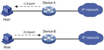
Configuration procedure
1. Export the certificate on Device A to specified files:
# Export the CA certificate to a .pem file.
<DeviceA> system-view
[DeviceA] pki export domain exportdomain pem ca filename pkicachain.pem
# Export the local certificate to a file named pkilocal.pem in PEM format, and use 3DES_CBC to encrypt the private key with the password 111111.
[DeviceA] pki export domain exportdomain pem local 3des-cbc 111111 filename pkilocal.pem
After the previous operations, the system generates three certificate files in PEM format: a CA certificate file and two local certificate files. The CA certificate file is named pkicachain.pem. The two local certificate files are named pkilocal.pem-signature and pkilocal.pem-encryption, and contain the private key for signature and encryption, respectively.
# Display the local certificate file pkilocal.pem-signature.
[DeviceA] quit
<DeviceA> more pkicachain.pem-sign
Bag Attributes
friendlyName:
localKeyID: 90 C6 DC 1D 20 49 4F 24 70 F5 17 17 20 2B 9E AC 20 F3 99 89
subject=/C=CN/O=OpenCA Labs/OU=Users/CN=subsign 11
issuer=/C=CN/L=shangdi/ST=pukras/O=OpenCA Labs/OU=docm/CN=subca1
-----BEGIN CERTIFICATE-----
MIIEgjCCA2qgAwIBAgILAJgsebpejZc5UwAwDQYJKoZIhvcNAQELBQAwZjELMAkG
…
-----END CERTIFICATE-----
Bag Attributes
friendlyName:
localKeyID: 90 C6 DC 1D 20 49 4F 24 70 F5 17 17 20 2B 9E AC 20 F3 99 89
Key Attributes: <No Attributes>
-----BEGIN ENCRYPTED PRIVATE KEY-----
MIICxjBABgkqhkiG9w0BBQ0wMzAbBgkqhkiG9w0BBQwwDgQIZtjSjfslJCoCAggA
…
-----END ENCRYPTED PRIVATE KEY-----
# Display the local certificate file pkilocal.pem-encryption.
<DeviceA> more pkicachain.pem-encr
Bag Attributes
friendlyName:
localKeyID: D5 DF 29 28 C8 B9 D9 49 6C B5 44 4B C2 BC 66 75 FE D6 6C C8
subject=/C=CN/O=OpenCA Labs/OU=Users/CN=subencr 11
issuer=/C=CN/L=shangdi/ST=pukras/O=OpenCA Labs/OU=docm/CN=subca1
-----BEGIN CERTIFICATE-----
MIIEUDCCAzigAwIBAgIKCHxnAVyzWhIPLzANBgkqhkiG9w0BAQsFADBmMQswCQYD
…
-----END CERTIFICATE-----
Bag Attributes
friendlyName:
localKeyID: D5 DF 29 28 C8 B9 D9 49 6C B5 44 4B C2 BC 66 75 FE D6 6C C8
Key Attributes: <No Attributes>
-----BEGIN ENCRYPTED PRIVATE KEY-----
MIICxjBABgkqhkiG9w0BBQ0wMzAbBgkqhkiG9w0BBQwwDgQI7H0mb4O7/GACAggA
…
-----END ENCRYPTED PRIVATE KEY-----
2. Download the certificate files pkicachain.pem, pkilocal.pem-sign, and pkilocal.pem-encr from Device A to the host through FTP. (Details not shown.)
3. Upload the certificate files pkicachain.pem, pkilocal.pem-sign, and pkilocal.pem-encr from the host to Device B through FTP. (Details not shown.)
4. Import the certificate files to Device B:
# Disable CRL checking. (You can configure CRL checking as required. This example assumes CRL checking is not required.)
<DeviceB> system-view
[DeviceB] pki domain importdomain
[DeviceB-pki-domain-importdomain] undo crl check enable
# Specify the RSA key pair for signature as sign, and the RSA key pair for encryption as encr for certificate request.
[DeviceB-pki-domain-importdomain] public-key rsa signature name sign encryption name encr
[DeviceB-pki-domain-importdomain] quit
# Import the CA certificate file pkicachain.pem in PEM format to the PKI domain.
[DeviceB] pki import domain importdomain pem ca filename pkicachain.pem
# Import the local certificate file pkilocal.pem-signature in PEM format to the PKI domain. The certificate file contains a key pair.
[DeviceB] pki import domain importdomain pem local filename pkilocal.pem-signature
Please input the password:******
# Import the local certificate file pkilocal.pem-encryption in PEM format to the PKI domain. The certificate file contains a key pair.
[DeviceB] pki import domain importdomain pem local filename pkilocal.pem-encryption
Please input the password:******
# Display the imported local certificate information on Device B.
[DeviceB] display pki certificate domain importdomain local
Certificate:
Data:
Version: 3 (0x2)
Serial Number:
98:2c:79:ba:5e:8d:97:39:53:00
Signature Algorithm: sha256WithRSAEncryption
Issuer: C=CN, L=shangdi, ST=pukras, O=OpenCA Labs, OU=docm, CN=subca1
Validity
Not Before: May 26 05:56:49 2011 GMT
Not After : Nov 22 05:56:49 2012 GMT
Subject: C=CN, O=OpenCA Labs, OU=Users, CN=subsign 11
Subject Public Key Info:
Public Key Algorithm: rsaEncryption
Public-Key: (1024 bit)
Modulus:
00:9f:6e:2f:f6:cb:3d:08:19:9a:4a:ac:b4:ac:63:
ce:8d:6a:4c:3a:30:19:3c:14:ff:a9:50:04:f5:00:
ee:a3:aa:03:cb:b3:49:c4:f8:ae:55:ee:43:93:69:
6c:bf:0d:8c:f4:4e:ca:69:e5:3f:37:5c:83:ea:83:
ad:16:b8:99:37:cb:86:10:6b:a0:4d:03:95:06:42:
ef:ef:0d:4e:53:08:0a:c9:29:dd:94:28:02:6e:e2:
9b:87:c1:38:2d:a4:90:a2:13:5f:a4:e3:24:d3:2c:
bf:98:db:a7:c2:36:e2:86:90:55:c7:8c:c5:ea:12:
01:31:69:bf:e3:91:71:ec:21
Exponent: 65537 (0x10001)
X509v3 extensions:
X509v3 Basic Constraints:
CA:FALSE
Netscape Cert Type:
SSL Client, S/MIME
X509v3 Key Usage:
Digital Signature, Non Repudiation
X509v3 Extended Key Usage:
TLS Web Client Authentication, E-mail Protection, Microsoft Smartcardlogin
Netscape Comment:
User Certificate of OpenCA Labs
X509v3 Subject Key Identifier:
AA:45:54:29:5A:50:2B:89:AB:06:E5:BD:0D:07:8C:D9:79:35:B1:F5
X509v3 Authority Key Identifier:
keyid:70:54:40:61:71:31:02:06:8C:62:11:0A:CC:A5:DB:0E:7E:74:DE:DD
X509v3 Subject Alternative Name:
email:[email protected]
X509v3 Issuer Alternative Name:
DNS:[email protected], DNS:, IP Address:1.1.2.2, IP Address:2.2.1.1
Authority Information Access:
CA Issuers - URI:http://titan/pki/pub/cacert/cacert.crt
OCSP - URI:http://titan:2560/
1.3.6.1.5.5.7.48.12 - URI:http://titan:830/
X509v3 CRL Distribution Points:
Full Name:
URI:http://192.168.40.130/pki/pub/crl/cacrl.crl
Signature Algorithm: sha256WithRSAEncryption
18:e7:39:9a:ad:84:64:7b:a3:85:62:49:e5:c9:12:56:a6:d2:
46:91:53:8e:84:ba:4a:0a:6f:28:b9:43:bc:e7:b0:ca:9e:d4:
1f:d2:6f:48:c4:b9:ba:c5:69:4d:90:f3:15:c4:4e:4b:1e:ef:
2b:1b:2d:cb:47:1e:60:a9:0f:81:dc:f2:65:6b:5f:7a:e2:36:
29:5d:d4:52:32:ef:87:50:7c:9f:30:4a:83:de:98:8b:6a:c9:
3e:9d:54:ee:61:a4:26:f3:9a:40:8f:a6:6b:2b:06:53:df:b6:
5f:67:5e:34:c8:c3:b5:9b:30:ee:01:b5:a9:51:f9:b1:29:37:
02:1a:05:02:e7:cc:1c:fe:73:d3:3e:fa:7e:91:63:da:1d:f1:
db:28:6b:6c:94:84:ad:fc:63:1b:ba:53:af:b3:5d:eb:08:b3:
5b:d7:22:3a:86:c3:97:ef:ac:25:eb:4a:60:f8:2b:a3:3b:da:
5d:6f:a5:cf:cb:5a:0b:c5:2b:45:b7:3e:6e:39:e9:d9:66:6d:
ef:d3:a0:f6:2a:2d:86:a3:01:c4:94:09:c0:99:ce:22:19:84:
2b:f0:db:3e:1e:18:fb:df:56:cb:6f:a2:56:35:0d:39:94:34:
6d:19:1d:46:d7:bf:1a:86:22:78:87:3e:67:fe:4b:ed:37:3d:
d6:0a:1c:0b
Certificate:
Data:
Version: 3 (0x2)
Serial Number:
08:7c:67:01:5c:b3:5a:12:0f:2f
Signature Algorithm: sha256WithRSAEncryption
Issuer: C=CN, L=shangdi, ST=pukras, O=OpenCA Labs, OU=docm, CN=subca1
Validity
Not Before: May 26 05:58:26 2011 GMT
Not After : Nov 22 05:58:26 2012 GMT
Subject: C=CN, O=OpenCA Labs, OU=Users, CN=subencr 11
Subject Public Key Info:
Public Key Algorithm: rsaEncryption
Public-Key: (1024 bit)
Modulus:
00:db:26:13:d3:d1:a4:af:11:f3:6d:37:cf:d0:d4:
48:50:4e:0f:7d:54:76:ed:50:28:c6:71:d4:48:ae:
4d:e7:3d:23:78:70:63:18:33:f6:94:98:aa:fa:f6:
62:ed:8a:50:c6:fd:2e:f4:20:0c:14:f7:54:88:36:
2f:e6:e2:88:3f:c2:88:1d:bf:8d:9f:45:6c:5a:f5:
94:71:f3:10:e9:ec:81:00:28:60:a9:02:bb:35:8b:
bf:85:75:6f:24:ab:26:de:47:6c:ba:1d:ee:0d:35:
75:58:10:e5:e8:55:d1:43:ae:85:f8:ff:75:81:03:
8c:2e:00:d1:e9:a4:5b:18:39
Exponent: 65537 (0x10001)
X509v3 extensions:
X509v3 Basic Constraints:
CA:FALSE
Netscape Cert Type:
SSL Server
X509v3 Key Usage:
Key Encipherment, Data Encipherment
Netscape Comment:
Server of OpenCA Labs
X509v3 Subject Key Identifier:
CC:96:03:2F:FC:74:74:45:61:38:1F:48:C0:E8:AA:18:24:F0:2B:AB
X509v3 Authority Key Identifier:
keyid:70:54:40:61:71:31:02:06:8C:62:11:0A:CC:A5:DB:0E:7E:74:DE:DD
X509v3 Subject Alternative Name:
email:[email protected]
X509v3 Issuer Alternative Name:
DNS:[email protected], DNS:, IP Address:1.1.2.2, IP Address:2.2.1.1
Authority Information Access:
CA Issuers - URI:http://titan/pki/pub/cacert/cacert.crt
OCSP - URI:http://titan:2560/
1.3.6.1.5.5.7.48.12 - URI:http://titan:830/
X509v3 CRL Distribution Points:
Full Name:
URI:http://192.168.40.130/pki/pub/crl/cacrl.crl
Signature Algorithm: sha256WithRSAEncryption
53:69:66:5f:93:f0:2f:8c:54:24:8f:a2:f2:f1:29:fa:15:16:
90:71:e2:98:e3:5c:c6:e3:d4:5f:7a:f6:a9:4f:a2:7f:ca:af:
c4:c8:c7:2c:c0:51:0a:45:d4:56:e2:81:30:41:be:9f:67:a1:
23:a6:09:50:99:a1:40:5f:44:6f:be:ff:00:67:9d:64:98:fb:
72:77:9e:fd:f2:4c:3a:b2:43:d8:50:5c:48:08:e7:77:df:fb:
25:9f:4a:ea:de:37:1e:fb:bc:42:12:0a:98:11:f2:d9:5b:60:
bc:59:72:04:48:59:cc:50:39:a5:40:12:ff:9d:d0:69:3a:5e:
3a:09:5a:79:e0:54:67:a0:32:df:bf:72:a0:74:63:f9:05:6f:
5e:28:d2:e8:65:49:e6:c7:b5:48:7d:95:47:46:c1:61:5a:29:
90:65:45:4a:88:96:e4:88:bd:59:25:44:3f:61:c6:b1:08:5b:
86:d2:4f:61:4c:20:38:1c:f4:a1:0b:ea:65:87:7d:1c:22:be:
b6:17:17:8a:5a:0f:35:4c:b8:b3:73:03:03:63:b1:fc:c4:f5:
e9:6e:7c:11:e8:17:5a:fb:39:e7:33:93:5b:2b:54:72:57:72:
5e:78:d6:97:ef:b8:d8:6d:0c:05:28:ea:81:3a:06:a0:2e:c3:
79:05:cd:c3
To display detailed information about the CA certificate, use the display pki certificate domain command.
Troubleshooting PKI configuration
This section provides troubleshooting information for common problems with PKI.
Failed to obtain the CA certificate
Symptom
The CA certificate cannot be obtained.
Analysis
· The network connection is down, for example, because the network cable is damaged or the connectors have bad contact.
· No trusted CA is specified.
· The certificate request URL is incorrect or not specified.
· The system time of the device is not synchronized with the CA server.
· The source IP address of the PKI protocol packets is not specified or not correct.
· The fingerprint of the root CA certificate is illegal.
Solution
1. Check for and fix any network connection problems.
2. Verify that the required configurations are correct.
3. Use ping to verify that the CA or RA is accessible from the specified certificate request URL.
4. Synchronize the system time of the device with the CA server.
5. Specify the correct source IP address for PKI protocol packets that the CA server can accept.
6. Verify the CA certificate's fingerprint on the CA server.
7. If the problem persists, contact H3C Support.
Failed to obtain local certificates
Symptom
No local certificates can be obtained.
Analysis
· The network connection is down.
· No CA certificate has been obtained before you try to obtain local certificates.
· The LDAP server is not configured or is incorrectly configured.
· No key pair is specified for the PKI domain for certificate request, or the specified key pair does not match the local certificates to the obtained.
· The PKI domain does not reference the PKI entity configuration, or the PKI entity configuration is incorrect.
· CRL checking is enabled, but CRLs do not exist locally or CRLs cannot be obtained.
· The CA server does not accept the source IP address specified in the PKI domain, or the source IP address is incorrect.
· The system time of the device is not synchronized with the CA server.
Solution
1. Check for and fix any network connection problems.
2. Obtain or import the CA certificate.
3. Configure the correct LDAP server.
4. Specify the key pair used for certificate request in the PKI domain, or remove the existing key pair and submit a certificate request again.
5. Check the registration policy on the CR or RA, and make sure the attributes of the PKI entity meet the policy requirements.
6. Obtain the CRL from the CRL repository.
7. Specify the correct source IP address that the CA server can accept. For the correct settings, contact the CA administrator.
8. Synchronize the system time of the device with the CA server.
9. If the problem persists, contact H3C Support.
Failed to request local certificates
Symptom
Local certificate requests cannot be submitted.
Analysis
· The network connection is down, for example, because the network cable is damaged or the connectors have bad contact.
· No CA certificate has been obtained before you submit the certificate request.
· The certificate request URL is incorrect or is not specified.
· The certificate request reception authority is incorrect or is not specified.
· The required parameters are not configured for the PKI entity or are mistakenly configured.
· No key pair is specified for the PKI domain for certificate request, or the key pair is changed during a certificate request process.
· Exclusive certificate request applications are running in the PKI domain.
· The PKI domain is not specified with the source IP address of the PKI protocol packets that the CA server can accept, or is specified with an incorrect one.
· The system time of the device is not synchronized with the CA server.
Solution
1. Check for and fix any network connection problemes.
2. Obtain or import the CA certificate.
3. Use ping to verify that the CA or RA is accessible from the specified certificate request URL.
4. Specify the correct certificate request URL.
5. Check the registration policy on the CR/RA, and make sure the attributes of the PKI entity meet the policy requirements.
6. Specify the key pair used for certificate request in the PKI domain, or remove the key pair specified in the PKI and submit a certificate request again.
7. Use pki abort-certificate-request domain to abort the certificate request.
8. Specify the correct source IP address that the CA server can accept. For the correct settings, contact the CA administrator.
9. Synchronize the system time of the device with the CA server.
10. If the problem persists, contact H3C Support.
Failed to obtain CRLs
Symptom
CRLs cannot be obtained.
Analysis
· The network connection is down, for example, because the network cable is damaged or the connectors have bad contact.
· No CA certificate has been obtained before you try to obtain CRLs.
· The URL of the CRL repository is not configured and cannot be obtained from the CA certificate or local certificates in the PKI domain.
· The specified URL of the CRL repository is incorrect.
· The device tries to obtain CRLs through SCEP, but experiences the following problems:
? The PKI domain does not have local certificates.
? The key pairs in the certificates have been changed.
? The PKI domain has incorrect URL for certificate request.
· The specified URL of the CRL repository does not contain the host name or IP address, and the LDAP server is incorrect or is not specified in the PKI domain.
· The PKI domain is not specified with the source IP address that the CA server can accept, or is specified with an incorrect one.
Solution
1. Check for and fix any network connection problems.
2. Obtain or import the CA certificate.
3. If the URL of the CRL repository cannot be obtained, verify that the following conditions exist:
? The URL for certificate request is valid.
? A local certificate has been successfully obtained.
? The local certificate contains a public key that matches the locally stored key pair.
4. Make sure the LDAP server address is contained in the CRL repository URL, or is configured in the PKI domain.
5. Make sure the CA server support publishing CRLs.
6. Specify a correct source IP address that the CA server can accept. For the correct settings, contact the CA administrator.
7. If the problem persists, contact H3C Support.
Failed to import the CA certificate
Symptom
The CA certificate cannot be imported.
Analysis
· CRL checking is enabled, but the device does not have a locally stored CRL and cannot obtain one.
· The specified format does not match the actual format of the file to be imported.
Solution
1. Use undo crl check enable to disable CRL checking.
2. Make sure the format of the imported file is correct.
3. If the problem persists, contact H3C Support.
Failed to import a local certificate
Symptom
A local certificate cannot be imported.
Analysis
· The PKI domain does not have a locally stored CA certificate, and the certificate file to be imported does not contain the CA certificate chain.
· CRL checking is enabled, but the device does not have a locally stored CRL and cannot obtain one.
· The specified format does not match the actual format of the file to be imported.
· The device and the certificate do not have the local key pair.
· The certificate has been revoked.
· The certificate is out of the validity period.
· The system time is wrong.
Solution
1. Obtain or import the CA certificate.
2. Use undo crl check enable to disable CRL checking, or obtain the CRL before you import certificates.
3. Make sure the format of the file to be imported is correct.
4. Make sure the certificate file contains the private key.
5. Make sure the certificate is not revoked.
6. Make sure the certificate is within the validity period.
7. Configure the correct system time for the device.
8. If the problem persists, contact H3C Support.
Failed to export certificates
Symptom
Certificates cannot be exported.
Analysis
· The PKI domain does not have local certificates when you export all certificates in PKCS12 format.
· The specified export path does not exist.
· The specified export path is invalid.
· The public key of the local certificate to be exported does not match the public key in the key pair of the PKI domain.
· The storage space of the device is full.
Solution
1. Obtain or request local certificates.
2. Use mkdir to create the required path.
3. Specify a correct export path.
4. Configure the correct key pair in the PKI domain.
5. Clear up the storage space of the device.
6. If the problem persists, contact H3C Support.
Failed to set the storage path
Symptom
The storage path for certificates or CRLs cannot be set.
Analysis
· The specified storage path does not exist.
· The specified storage path is illegal.
· The storage space of the device is full.
Solution
1. Use mkdir to create the path.
2. Specify a valid storage path for certificates or CRLs.
3. Clear up the storage space of the device.
4. If the problem persists, contact H3C Support.
Configuring SSL
Overview
Secure Sockets Layer (SSL) is a cryptographic protocol that provides communication security for TCP-based application layer protocols such as HTTP. SSL has been widely used in applications such as e-business and online banking to provide secure data transmission over the Internet.
SSL security services
SSL provides the following security services:
· Privacy—SSL uses a symmetric encryption algorithm to encrypt data and uses an asymmetric key algorithm such as RSA to encrypt the key used by the symmetric encryption algorithm. For more information about RSA, see "Managing public keys"
· Authentication—SSL uses certificate-based digital signatures to authenticate the SSL server and client. The SSL server and client obtain digital certificates through PKI. For more information about PKI and digital certificates, see "Configuring PKI"
· Integrity—SSL uses the message authentication code (MAC) to verify message integrity. It uses a MAC algorithm and a key to transform a message of any length to a fixed-length message. Any change to the original message will result in a change to the calculated fixed-length message. As shown in Figure 23, the message integrity verification process is as follows:
a. The sender uses a MAC algorithm and a key to calculate a MAC value for a message. Then, it appends the MAC value to the message, and sends the message to the receiver.
b. The receiver uses the same key and MAC algorithm to calculate a MAC value for the received message, and compares it with the MAC value appended to the message.
c. If the two MAC values match, the receiver considers the message intact. Otherwise, the receiver considers that the message was tampered with and it discards the message.
Figure 23 MAC algorithm diagram
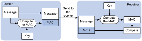
SSL protocol stack
The SSL protocol stack includes the following protocols:
· SSL record protocol at the lower layer.
· SSL handshake protocol, SSL change cipher spec protocol, and SSL alert protocol at the upper layer.
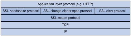
The following describes the major functions of SSL protocols:
· SSL record protocol—Fragments data received from the upper layer, computes and adds MAC to the data, and encrypts the data.
· SSL handshake protocol—Negotiates the cipher suite used for secure communication, authenticates the server and client, and securely exchanges the keys between the server and client. The cipher suite that needs to be negotiated includes the symmetric encryption algorithm, key exchange algorithm, and MAC algorithm.
· SSL change cipher spec protocol—Notifies the receiver that subsequent packets are to be protected based on the negotiated cipher suite and key.
· SSL alert protocol—Sends alert messages to the receiving party. An alert message contains the alert severity level and a description.
Feature and software version compatibility
The SSL feature is available in Release 1138P01 and later versions.
FIPS compliance
The device supports the FIPS mode that complies with NIST FIPS 140-2 requirements. Support for features, commands, and parameters might differ in FIPS mode (see "Configuring FIPS") and non-FIPS mode.
SSL configuration task list
|
Tasks at a glance |
Remarks |
|
Perform this configuration task on the SSL server. |
|
|
Perform this configuration task on the SSL client. |
Configuring an SSL server policy
An SSL server policy is a set of SSL parameters used by the SSL server. An SSL server policy takes effect only after it is associated with an application such as HTTPS.
|
|
NOTE: · SSL versions include SSL 2.0, SSL 3.0, and TLS 1.0 (or SSL 3.1). By default, the SSL server can communicate with clients running SSL 3.0 or TLS 1.0. When the server receives an SSL 2.0 Client Hello message from a client supporting both SSL 2.0 and SSL 3.0/TLS 1.0, it notifies the client to use SSL 3.0 or TLS 1.0 for communication. · You can disable SSL 3.0 on the device to enhance system security. |
To configure an SSL server policy:
|
Step |
Command |
Remarks |
|
1. Enter system view. |
system-view |
N/A |
|
2. (Optional.) Disable SSL 3.0 for the SSL server. |
By default, SSL 3.0 is enabled. |
|
|
3. Create an SSL server policy and enter its view. |
ssl server-policy policy-name |
By default, no SSL server policies exist on the device. |
|
4. (Optional.) Specify a PKI domain for the SSL server policy. |
pki-domain domain-name |
By default, no PKI domain is specified for an SSL server policy. If SSL server authentication is required, you must specify a PKI domain and request a local certificate for the SSL server in the domain. For information about how to create and configure a PKI domain, see "Configuring PKI" |
|
5. Specify the cipher suites that the SSL server policy supports. |
·
In non-FIPS mode: ·
In FIPS mode: |
By default, an SSL server policy supports all cipher suites. |
|
6. Set the maximum number of sessions that the SSL server can cache. |
session cachesize size |
By default, an SSL server can cache a maximum of 500 sessions. |
|
7. Enable the SSL server to authenticate SSL clients through digital certificates. |
client-verify enable |
By default, SSL client authentication is disabled. |
Configuring an SSL client policy
An SSL client policy is a set of SSL parameters that the client uses to establish a connection to the server. An SSL client policy takes effect only after it is associated with an application such as DDNS.
You can specify the SSL version (SSL 3.0 or TLS 1.0) for an SSL client policy:
· If TLS 1.0 is specified and SSL 3.0 is not disabled, the client first uses TLS 1.0 to connect to the SSL server. If the connection attempt fails, the client uses SSL 3.0.
· If TLS 1.0 is specified and SSL 3.0 is disabled, the client only uses TLS 1.0 to connect to the SSL server.
· If SSL 3.0 is specified, the client uses SSL 3.0 to connect to the SSL server, whether you disable SSL 3.0 or not.
As a best practice to enhance system security, disable SSL 3.0 on the device and specify TLS 1.0 for an SSL client policy.
To configure an SSL client policy:
|
Step |
Command |
Remarks |
|
1. Enter system view. |
system-view |
N/A |
|
2. (Optional.) Disable SSL 3.0 for the SSL server. |
ssl version ssl3.0 disable |
By default, SSL 3.0 is enabled. |
|
3. Create an SSL client policy and enter its view. |
ssl client-policy policy-name |
By default, no SSL client policies exist on the device. |
|
4. (Optional.) Specify a PKI domain for the SSL client policy. |
pki-domain domain-name |
By default, no PKI domain is specified for an SSL client policy. If SSL client authentication is required, you must specify a PKI domain and request a local certificate for the SSL client in the PKI domain. For information about how to create and configure a PKI domain, see "Configuring PKI" |
|
5. Specify the preferred cipher suite for the SSL client policy. |
·
In non-FIPS mode: ·
In FIPS mode: |
·
In non-FIPS mode: ·
In FIPS mode: |
|
6. Specify the SSL version for the SSL client policy. |
·
In non-FIPS mode: ·
In FIPS mode: |
By default, an SSL client policy uses TLS 1.0. |
|
7. Enable the SSL client to authenticate servers through digital certificates. |
server-verify enable |
By default, SSL server authentication is enabled. |
Displaying and maintaining SSL
Execute display commands in any view.
|
Task |
Command |
|
Display SSL server policy information. |
display ssl server-policy [ policy-name ] |
|
Display SSL client policy information. |
display ssl client-policy [ policy-name ] |
Configuring IPsec
The term "interface" in this chapter collectively refers to Layer 3 interfaces, including VLAN interfaces and Layer 3 Ethernet interfaces. You can set an Ethernet port as a Layer 3 interface by using the port link-mode route command (see Layer 2—LAN Switching Configuration Guide).
|
|
CAUTION: · If you configure both IPsec and QoS on an interface, make sure the IPsec traffic classification rules match the QoS traffic classification rules. If the rules do not match, QoS might classify the packets of one IPsec SA to different queues, causing packets to be sent out of order. When IPsec anti-replay is enabled, IPsec will drop the incoming packets that are out of the anti-replay window, resulting in packet loss. IPsec traffic classification rules are determined by the referenced ACL rules. For information about QoS classification rules, see ACL and QoS Configuration Guide. · ACLs for IPsec take effect only on traffic that is generated by the device and traffic that is destined for the device. They do not take effect on traffic forwarded through the device. |
Overview
IP Security (IPsec) is defined by the IETF to provide interoperable, high-quality, cryptography-based security for IP communications. It transmits data in a secure channel established between two endpoints (such as two security gateways). Such a secure channel is usually called an IPsec tunnel.
IPsec is a security framework that comprises a set of protocols, including Authentication Header (AH), Encapsulating Security Payload (ESP), Internet Key Exchange (IKE), and algorithms for authentication and encryption. AH and ESP are security protocols that provide security services. IKE performs automatic key exchange. For more information about IKE, see "Configuring IKE."
IPsec provides the following security services for data packets in the IP layer:
· Confidentiality—The sender encrypts packets before transmitting them over the Internet, protecting the packets from being eavesdropped en route.
· Data integrity—The receiver verifies the packets received from the sender to make sure they are not tampered with during transmission.
· Data origin authentication—The receiver verifies the authenticity of the sender.
· Anti-replay—The receiver examines packets and drops outdated and duplicate packets.
IPsec delivers the following benefits:
· Reduced key negotiation overhead and simplified maintenance by supporting the IKE protocol. IKE provides automatic key negotiation and automatic IPsec security association (SA) setup and maintenance.
· Good compatibility. You can apply IPsec to all IP-based application systems and services without modifying them.
· Encryption on a per-packet rather than per-flow basis. Per-packet encryption allows for flexibility and greatly enhances IP security.
Security protocols and encapsulation modes
Security protocols
IPsec comes with two security protocols, AH and ESP. They define how to encapsulate IP packets and the security services that they can provide.
· AH (protocol 51) defines the encapsulation of the AH header in an IP packet, as shown in Figure 27. AH can provide data origin authentication, data integrity, and anti-replay services to prevent data tampering, but it cannot prevent eavesdropping. Therefore, it is suitable for transmitting non-confidential data. AH supports authentication algorithms HMAC-MD5 and HMAC-SHA1.
· ESP (protocol 50) defines the encapsulation of the ESP header and trailer in an IP packet, as shown in Figure 27. ESP can provide data encryption, data origin authentication, data integrity, and anti-replay services. Unlike AH, ESP can guarantee data confidentiality because it can encrypt the data before encapsulating the data to IP packets. ESP supports encryption algorithms such as DES, 3DES, and AES, and authentication algorithms HMAC-MD5 and HMAC-SHA1.
Both AH and ESP provide authentication services, but the authentication service provided by AH is stronger. In practice, you can choose either or both security protocols. When both AH and ESP are used, an IP packet is encapsulated first by ESP and then by AH.
Encapsulation modes
IPsec supports the following encapsulation modes:
· Transport mode—The security protocols protect the upper layer data of an IP packet. Only the transport layer data is used to calculate the security protocol headers. The calculated security protocol headers and the encrypted data (only for ESP encapsulation) are placed after the original IP header. You can use the transport mode when end-to-end security protection is required (the secured transmission start and end points are the actual start and end points of the data). The transport mode is typically used for protecting host-to-host communications, as shown in Figure 25.
Figure 25 IPsec protection in transport mode
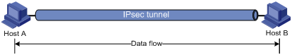
· Tunnel mode—The security protocols protect the entire IP packet. The entire IP packet is used to calculate the security protocol headers. The calculated security protocol headers and the encrypted data (only for ESP encapsulation) are encapsulated in a new IP packet. In this mode, the encapsulated packet has two IP headers. The inner IP header is the original IP header. The outer IP header is added by the network device that provides the IPsec service. You must use the tunnel mode when the secured transmission start and end points are not the actual start and end points of the data packets (for example, when two gateways provide IPsec but the data start and end points are two hosts behind the gateways). The tunnel mode is typically used for protecting gateway-to-gateway communications, as shown in Figure 26.
Figure 26 IPsec protection in tunnel mode
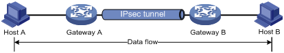
Figure 27 shows how the security protocols encapsulate an IP packet in different encapsulation modes.
Figure 27 Security protocol encapsulations in different modes
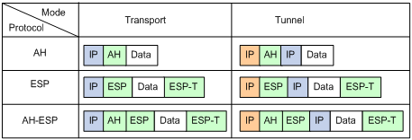
Security association
A security association (SA) is an agreement negotiated between two communicating parties called "IPsec peers." An SA comprises a set of parameters for data protection, including security protocols (AH, ESP, or both), encapsulation mode (transport mode or tunnel mode), authentication algorithm (HMAC-MD5 or HMAC-SHA1), encryption algorithm (DES, 3DES, or AES), and shared keys and their lifetimes.
An SA is unidirectional. At least two SAs are needed to protect data flows in a bidirectional communication. If two peers want to use both AH and ESP to protect data flows between them, they construct an independent SA for each protocol in each direction.
An SA is uniquely identified by a triplet, which consists of the security parameter index (SPI), destination IP address, and security protocol identifier. An SPI is a 32-bit number that identifies an SA. It is transmitted in the AH/ESP header.
An SA can be set up manually or through IKE.
· Manual mode—Configure all parameters for the SA through commands. This configuration mode is complex and does not support some advanced features (such as periodic key update), but it can implement IPsec without IKE. This mode is mainly used in small and static networks or when the number of IPsec peers in the network is small.
· IKE negotiation mode—The peers negotiate and maintain the SA through IKE. This configuration mode is simple and has good expansibility. As a best practice, set up SAs through IKE negotiations in medium- and large-scale dynamic networks.
A manually configured SA never ages out. An IKE-created SA has a lifetime, which comes in two types:
· Time-based lifetime—Defines how long the SA can be valid after it is created.
· Traffic-based lifetime—Defines the maximum traffic that the SA can process.
If both lifetime timers are configured for an SA, the SA becomes invalid when either of the lifetime timers expires. Before the SA expires, IKE negotiates a new SA, which takes over immediately after its creation.
Authentication and encryption
Authentication algorithms
IPsec uses hash algorithms to perform authentication. A hash algorithm produces a fixed-length digest for an arbitrary-length message. IPsec peers respectively calculate message digests for each packet. The receiver compares the local digest with that received from the sender. If the digests are identical, the receiver considers the packet intact and the sender's identity valid. IPsec uses the Hash-based Message Authentication Code (HMAC) based authentication algorithms, including HMAC-MD5 and HMAC-SHA1. Compared with HMAC-SHA1, HMAC-MD5 is faster but less secure.
Encryption algorithms
IPsec uses symmetric encryption algorithms, which encrypt and decrypt data by using the same keys. The following encryption algorithms are available for IPsec on the device:
· DES—Encrypts a 64-bit plaintext block with a 56-bit key. DES is the least secure but the fastest algorithm.
· 3DES—Encrypts plaintext data with three 56-bit DES keys. The key length totals up to 168 bits. It provides moderate security strength and is slower than DES.
· AES—Encrypts plaintext data with a 128-bit, 192-bit, or 256-bit key. AES provides the highest security strength and is slower than 3DES.
IPsec implementation
To implement IPsec protection for packets between two peers, complete the following tasks on each peer:
· Configure an IPsec policy, which defines the range of packets to be protected by IPsec and the security parameters used for the protection.
· Apply the IPsec policy to an interface.
When you apply an IPsec policy to an interface, you implement IPsec based on the interface. Packets received and sent by the interface are protected according to the IPsec policy.
IPsec protects packets as follows:
· When an IPsec peer identifies the packets to be protected according to the IPsec policy, it sets up an IPsec tunnel and sends the packet to the remote peer through the tunnel. The IPsec tunnel can be manually configured beforehand, or it can be set up through IKE negotiation triggered by the packet. The IPsec tunnels are actually the IPsec SAs. The inbound packets are protected by the inbound SA, and the outbound packets are protected by the outbound SA.
· When the remote IPsec peer receives the packet, it drops, de-encapsulates, or directly forwards the packet according to the configured IPsec policy.
Interface-based IPsec supports setting up IPsec tunnels based on ACLs.
ACL-based IPsec
To implement ACL-based IPsec, configure an ACL to define the data flows to be protected, reference the ACL in an IPsec policy, and then apply the IPsec policy to an interface. When packets sent by the interface match the permit rule of the ACL, the packets are protected by the outbound IPsec SA and encapsulated with IPsec. When the interface receives an IPsec packet whose destination address is the IP address of the local device, it searches for the inbound IPsec SA according to the SPI carried in the IPsec packet header for de-encapsulation. If the de-encapsulated packet matches the permit rule of the ACL, the device processes the packet. Otherwise, it drops the packet.
The device supports the following data flow protection modes:
· Standard mode—One IPsec tunnel protects one data flow. The data flow permitted by an ACL rule is protected by one IPsec tunnel that is established solely for it.
· Aggregation mode—One IPsec tunnel protects all data flows permitted by all the rules of an ACL. This mode is only used to communicate with old-version devices.
· Per-host mode—One IPsec tunnel protects one host-to-host data flow. One host-to-host data flow is identified by one ACL rule and protected by one IPsec tunnel established solely for it. This mode consumes more system resources when multiple data flows exist between two subnets to be protected.
Protocols and standards
· RFC 2401, Security Architecture for the Internet Protocol
· RFC 2402, IP Authentication Header
· RFC 2406, IP Encapsulating Security Payload
IPsec tunnel establishment
Implementing ACL-based IPsec protects packets identified by an ACL. To establish an ACL-based IPsec tunnel, configure an IPsec policy, reference an ACL in the policy, and apply the policy to an interface (see "Implementing ACL-based IPsec").
Implementing ACL-based IPsec
Feature restrictions and guidelines
ACLs for IPsec take effect only on traffic that is generated by the device and traffic that is destined for the device. They do not take effect on traffic forwarded through the device. For example, an ACL-based IPsec tunnel can protect log messages the device sends to a log server, but it cannot protect all the data flows and voice flows that are forwarded by the device. For more information about configuring an ACL for IPsec, see "Configuring an ACL."
Typically, IKE uses UDP port 500 for communication, and AH and ESP use the protocol numbers 51 and 50. Make sure traffic of these protocols is not denied on the interfaces with IKE or IPsec configured.
ACL-based IPsec configuration task list
The generic configuration procedure for implementing ACL-based IPsec is as follows:
1. Configure an ACL for identifying data flows to be protected. To use IPsec to protect VPN traffic, you do not need to specify the VPN parameters in the ACL rules.
2. Configure IPsec transform sets to specify the security protocols, authentication and encryption algorithms, and the encapsulation mode.
3. Configure an IPsec policy to associate data flows with the IPsec transform sets, specify the SA negotiation mode, the peer IP addresses (the start and end points of the IPsec tunnel), the required keys, and the SA lifetime.
An IPsec policy is a set of IPsec policy entries that have the same name but different sequence numbers. In the same IPsec policy, an IPsec policy entry with a smaller sequence number has a higher priority.
4. Apply the IPsec policy to an interface.
Complete the following tasks to configure ACL-based IPsec:
|
Tasks at a glance |
|
(Required.) Configuring an ACL |
|
(Required.) Configuring an IPsec transform set |
|
(Required.) Configure an IPsec policy (use either method): |
|
(Required.) Applying an IPsec policy to an interface |
|
(Optional.) Enabling ACL checking for de-encapsulated packets |
|
(Optional.) Configuring IPsec anti-replay |
|
(Optional.) Binding a source interface to an IPsec policy |
|
(Optional.) Enabling QoS pre-classify |
|
(Optional.) Enabling logging of IPsec packets |
|
(Optional.) Configuring the DF bit of IPsec packets |
|
(Optional.) Configuring SNMP notifications for IPsec |
Configuring an ACL
IPsec uses ACLs to identify the traffic to be protected.
Keywords in ACL rules
An ACL is a collection of ACL rules. Each ACL rule is a deny or permit statement. A permit statement identifies a data flow protected by IPsec, and a deny statement identifies a data flow that is not protected by IPsec. With IPsec, a packet is matched against the referenced ACL rules and processed according to the first rule that it matches:
· Each ACL rule matches both the outbound traffic and the returned inbound traffic.
· In the outbound direction, if a permit statement is matched, IPsec considers that the packet requires protection and continues to process it. If a deny statement is matched or no match is found, IPsec considers that the packet does not require protection and delivers it to the next module.
· In the inbound direction:
? Non-IPsec packets that match a permit statement are dropped.
? IPsec packets destined for the device itself are de-encapsulated. By default, the de-encapsulated packets are compared against the ACL rules. Only those that match a permit statement are processed. Other packets are dropped. If ACL checking for de-encapsulated packets is disabled, the de-encapsulated packets are not compared against the ACL rules and are directly processed by other modules.
When defining ACL rules for IPsec, follow these guidelines:
· Permit only data flows that need to be protected and use the any keyword with caution. With the any keyword specified in a permit statement, all outbound traffic matching the permit statement will be protected by IPsec and all inbound IPsec packets matching the permit statement will be received and processed, but all inbound non-IPsec packets will be dropped. This will cause all the inbound traffic that does not need IPsec protection to be dropped.
· Avoid statement conflicts in the scope of IPsec policy entries. When creating a deny statement, be careful with its matching scope and matching order relative to permit statements. The policy entries in an IPsec policy have different match priorities. ACL rule conflicts between them are prone to cause mistreatment of packets. For example, when configuring a permit statement for an IPsec policy entry to protect an outbound traffic flow, you must avoid the situation that the traffic flow matches a deny statement in a higher priority IPsec policy entry. Otherwise, the packets will be sent out as normal packets. If they match a permit statement at the receiving end, they will be dropped by IPsec.
Mirror image ACLs
To make sure SAs can be set up and the traffic protected by IPsec can be processed correctly between two IPsec peers, create mirror image ACLs on the IPsec peers.
Configuring an IPsec transform set
An IPsec transform set, part of an IPsec policy, defines the security parameters for IPsec SA negotiation, including the security protocol, encryption algorithms, and authentication algorithms.
Changes to an IPsec transform set affect only SAs negotiated after the changes. To apply the changes to existing SAs, execute the reset ipsec sa command to clear the SAs so that they can be set up by using the updated parameters.
To configure an IPsec transform set:
|
Step |
Command |
Remarks |
|
1. Enter system view. |
system-view |
N/A |
|
2. Create an IPsec transform set and enter its view. |
ipsec transform-set transform-set-name |
By default, no IPsec transform set exists. |
|
3. Specify the security protocol for the IPsec transform set. |
protocol { ah | ah-esp | esp } |
Optional. By default, the IPsec transform set uses ESP as the security protocol. |
|
4. Specify the security algorithms. |
·
(In non-FIPS mode.) Specify
the encryption algorithm for ESP: ·
(In FIPS mode.) Specify
the encryption algorithm for ESP: ·
(In non-FIPS mode.) Specify
the authentication algorithm for ESP: ·
(In FIPS mode.) Specify
the authentication algorithm for ESP: ·
(In non-FIPS mode.) Specify
the authentication algorithm for AH: ·
(In FIPS mode.) Specify
the authentication algorithm for AH: |
Configure at least one command. By default, no security algorithm is specified. You can specify security algorithms for a security protocol only when the security protocol is used by the transform set. For example, you can specify the ESP-specific security algorithms only when you select ESP or AH-ESP as the security protocol. If you use ESP in FIPS mode, you must specify both the ESP encryption algorithm and the ESP authentication algorithm. You can specify multiple algorithms by using one command, and the algorithm specified earlier has a higher priority. |
|
5. Specify the mode in which the security protocol encapsulates IP packets. |
encapsulation-mode { transport | tunnel } |
By default, the security protocol encapsulates IP packets in tunnel mode. The transport mode applies only when the source and destination IP addresses of data flows match those of the IPsec tunnel. |
|
6. (Optional.) Enable the Perfect Forward Secrecy (PFS) feature for the IPsec policy. |
·
In non-FIPS mode: ·
In FIPS mode: |
By default, the PFS feature is not used for SA negotiation. For more information about PFS, see "Configuring IKE." The security level of the Diffie-Hellman (DH) group of the initiator must be higher than or equal to that of the responder. The end without the PFS feature performs SA negotiation according to the PFS requirements of the peer end. |
Configuring a manual IPsec policy
In a manual IPsec policy, the parameters are configured manually, such as the keys, the SPIs, and the IP addresses of the two ends in tunnel mode.
Configuration restrictions and guidelines
To guarantee successful SA negotiations, make sure the IPsec configurations at the two ends of an IPsec tunnel meet the following requirements:
· The IPsec policies at the two ends must have IPsec transform sets that use the same security protocols, security algorithms, and encapsulation mode.
· The remote IPv4 address configured on the local end must be the same as the primary IPv4 address of the interface applied with the IPsec policy at the remote end.
· At each end, configure parameters for both the inbound SA and the outbound SA, and make sure the SAs in each direction are unique: For an outbound SA, make sure its triplet (remote IP address, security protocol, and SPI) is unique. For an inbound SA, make sure its SPI is unique.
· The local inbound SA must use the same SPI and keys as the remote outbound SA. The same is true of the local outbound SA and remote inbound SA.
· The keys for the local and remote inbound and outbound SAs must be in the same format. For example, if the local inbound SA uses a key in characters, the local outbound SA and remote inbound and outbound SAs must use keys in characters.
Configuration procedure
To configure a manual IPsec policy:
|
Step |
Command |
Remarks |
|
1. Enter system view. |
system-view |
N/A |
|
2. Create a manual IPsec policy entry and enter its view. |
ipsec policy policy-name seq-number manual |
By default, no IPsec policy exists. |
|
3. (Optional.) Configure a description for the IPsec policy. |
description text |
By default, no description is configured. |
|
4. Specify an ACL for the IPsec policy. |
security acl { acl-number | name acl-name } |
By default, an IPsec policy references no ACL. An IPsec policy can reference only one ACL. |
|
5. Specify an IPsec transform set for the IPsec policy. |
transform-set transform-set-name |
By default, an IPsec policy references no IPsec transform set. A manual IPsec policy can reference only one IPsec transform set. |
|
6. Specify the remote IP address of the IPsec tunnel. |
remote-address ipv4-address |
By default, the remote IP address of the IPsec tunnel is not specified. The local IPv4 address of the IPsec tunnel is the primary IPv4 address of the interface to which the IPsec policy is applied. |
|
7. Configure an SPI for the inbound or outbound IPsec SA. |
·
To configure an SPI for the inbound IPsec SA: ·
To configure an SPI for the outbound IPsec SA: |
By default, no SPI is configured for the inbound or outbound IPsec SA. |
|
8. Configure keys for the IPsec SA. |
·
Configure an authentication key in
hexadecimal format for AH: ·
Configure an authentication key in character
format for AH: ·
Configure a key in character format for
ESP: ·
Configure an authentication key in hexadecimal
format for ESP: ·
Configure an encryption key in hexadecimal format
for ESP: |
By default, no keys are configured for the IPsec SA. Configure keys correctly for the security protocol (AH, ESP, or both) you have specified in the IPsec transform set referenced by the IPsec policy. If you configure a key in both the character and the hexadecimal formats, only the most recent configuration takes effect. If you configure a key in character format for ESP, the device automatically generates an authentication key and an encryption key for ESP. |
Configuring an IKE-based IPsec policy
In an IKE-based IPsec policy, the parameters are automatically negotiated through IKE.
To configure an IKE-based IPsec policy, directly configure it by configuring the parameters in IPsec policy view.
Configuration restrictions and guidelines
The IPsec configurations at the two ends of an IPsec tunnel must meet the following requirements:
· The IPsec policies at the two tunnel ends must have IPsec transform sets that use the same security protocols, security algorithms, and encapsulation mode.
· The IPsec policies at the two tunnel ends must have the same IKE profile parameters.
· An IKE-based IPsec policy can reference up to six IPsec transform sets. During an IKE negotiation, IKE searches for a fully matched IPsec transform set at the two ends of the IPsec tunnel. If no match is found, no SA can be set up, and the packets expecting to be protected will be dropped.
· The remote IP address of the IPsec tunnel is required on an IKE negotiation initiator and is optional on the responder. The remote IP address specified on the local end must be the same as the local IP address specified on the remote end.
For an IPsec SA established through IKE negotiation:
· The IPsec SA uses the local lifetime settings or those proposed by the peer, whichever are smaller.
· The IPsec SA can have both a time-based lifetime and a traffic-based lifetime. The IPsec SA expires when either lifetime expires.
Configuration procedure
|
Step |
Command |
Remarks |
|
1. Enter system view. |
system-view |
N/A |
|
2. Create an IKE-based IPsec policy entry and enter its view. |
ipsec policy policy-name seq-number isakmp |
By default, no IPsec policy exists. |
|
3. (Optional.) Configure a description for the IPsec policy. |
description text |
By default, no description is configured. |
|
4. Specify an ACL for the IPsec policy. |
security acl { acl-number | name acl-name } [ aggregation | per-host ] |
By default, no ACL is specified for the IPsec policy. An IPsec policy can reference only one ACL. |
|
5. Specify IPsec transform sets for the IPsec policy. |
transform-set transform-set-name&<1-6> |
By default, the IPsec policy references no IPsec transform set. |
|
6. Specify an IKE profile for the IPsec policy. |
ike-profile profile-name |
By default, the IPsec policy references no IKE profile, and the device selects an IKE profile configured in system view for negotiation. If no IKE profile is configured, the globally configured IKE settings are used. An IPsec policy can reference only one IKE profile, and it cannot reference any IKE profile that is already referenced by another IPsec policy. For more information about IKE profiles, see "Configuring IKE." |
|
7. Specify the local IP address of the IPsec tunnel. |
local-address ipv4-address |
By default, the local IPv4 address of IPsec tunnel is the primary IPv4 address of the interface to which the IPsec policy is applied. The local IP address specified by this command must be the same as the IP address used as the local IKE identity. |
|
8. Specify the remote IP address of the IPsec tunnel. |
remote-address { host-name | ipv4-address } |
By default, the remote IP address of the IPsec tunnel is not specified. |
|
9. Set the IPsec SA lifetime. |
sa duration { time-based seconds | traffic-based kilobytes } |
By default, the global SA lifetime is used. |
|
10. (Optional.) Set the IPsec SA idle timeout. |
sa idle-time seconds |
By default, the global SA idle timeout is used. |
|
11. Return to system view. |
quit |
N/A |
|
12. Set the global SA lifetime. |
ipsec sa global-duration { time-based seconds | traffic-based kilobytes } |
By default, the time-based SA lifetime is 3600 seconds, and the traffic-based SA lifetime is 1843200 kilobytes. |
|
13. (Optional.) Enable the global IPsec SA idle timeout feature, and set the global SA idle timeout. |
ipsec sa idle-time seconds |
By default, the global IPsec SA idle timeout feature is disabled. |
Applying an IPsec policy to an interface
You can apply an IPsec policy to an interface to protect certain data flows. To cancel the IPsec protection, remove the application of the IPsec policy.
For each packet to be sent out of an interface applied with an IPsec policy, the interface looks through the IPsec policy entries in the IPsec policy in ascending order of sequence numbers. If the packet matches the ACL of an IPsec policy entry, the interface uses the IPsec policy entry to protect the packet. If no match is found, the interface sends the packet out without IPsec protection.
When the interface receives an IPsec packet whose destination address is the IP address of the local device, it searches for the inbound IPsec SA according to the SPI carried in the IPsec packet header for de-encapsulation. If the de-encapsulated packet matches the permit rule of the ACL, the device processes the packet. Otherwise, it drops the packet.
An interface can reference only one IPsec policy. An IKE-based IPsec policy can be applied to more than one interface, but a manual IPsec policy can be applied to only one interface.
To apply an IPsec policy to an interface:
|
Step |
Command |
Remarks |
|
1. Enter system view. |
system-view |
N/A |
|
2. Enter interface view. |
interface interface-type interface-number |
N/A |
|
3. Apply an IPsec policy to the interface. |
ipsec apply policy policy-name |
By default, no IPsec policy is applied to the interface. An interface can reference only one IPsec policy. An IKE-mode IPsec policy can be applied to multiple interfaces, and a manual IPsec policy can be applied to only one interface. |
Enabling ACL checking for de-encapsulated packets
This feature uses the ACL in the IPsec policy to match the IP packets that are de-encapsulated from incoming IPsec packets in tunnel mode, and it discards the IP packets that fail to match the ACL to avoid attacks using forged packets.
To enable ACL checking for de-encapsulated packets:
|
Step |
Command |
Remarks |
|
1. Enter system view. |
system-view |
N/A |
|
2. Enable ACL checking for de-encapsulated packets. |
ipsec decrypt-check enable |
By default, this feature is enabled. |
Configuring IPsec anti-replay
The IPsec anti-replay feature protects networks against anti-replay attacks by using a sliding window mechanism called anti-replay window. This feature checks the sequence number of each received IPsec packet against the current IPsec packet sequence number range of the sliding window. If the sequence number is not in the current sequence number range, the packet is considered a replayed packet and is discarded.
IPsec packet de-encapsulation involves complicated calculation. De-encapsulation of replayed packets is not required, and the de-encapsulation process consumes large amounts of resources and degrades performance, resulting in DoS. IPsec anti-replay can check and discard replayed packets before de-encapsulation.
In some situations, service data packets are received in a different order than their original order. The IPsec anti-replay feature drops them as replayed packets, which impacts communications. If this happens, disable IPsec anti-replay checking or adjust the size of the anti-replay window as required.
IPsec anti-replay does not affect manually created IPsec SAs. According to the IPsec protocol, only IKE-based IPsec SAs support anti-replay checking.
|
|
IMPORTANT: · IPsec anti-replay is enabled by default. Failure to detect anti-replay attacks might result in denial of services. Use caution when you disable IPsec anti-replay. · Specify an anti-replay window size that is as small as possible to reduce the impact on system performance. · On a distributed device, multiple cards might process packets for the same VLAN interface. However, IPsec anti-replay requires that packets sent and received on the same VLAN interface be processed by the same card. To implement IPsec anti-replay on a distributed device, use the service command in VLAN interface view to specify a card for forwarding the traffic on the interface. For more information about the service command, see Layer 2—LAN Switching Command Reference. |
To configure IPsec anti-replay:
|
Step |
Command |
Remarks |
|
1. Enter system view. |
system-view |
N/A |
|
2. Enable IPsec anti-replay. |
ipsec anti-replay check |
By default, IPsec anti-replay is enabled. |
|
3. Set the size of the IPsec anti-replay window. |
ipsec anti-replay window width |
The default size is 64. |
Binding a source interface to an IPsec policy
For high availability, a core device is usually connected to an ISP through two links, which operate in backup or load sharing mode. The two interfaces negotiate with their peers to establish IPsec SAs respectively. When one interface fails and a link failover occurs, the other interface needs to take some time to re-negotiate SAs, resulting in service interruption.
To solve these problems, bind a source interface to an IPsec policy and apply the policy to both interfaces. This enables the two physical interfaces to use the same source interface to negotiate IPsec SAs. As long as the source interface is up, the negotiated IPsec SAs will not be removed and will keep working, regardless of link failover.
Follow these guidelines when you perform this task:
· Only the IKE-based IPsec policies can be bound to a source interface.
· An IPsec policy can be bound to only one source interface.
· A source interface can be bound to multiple IPsec policies.
· If the source interface bound to an IPsec policy is removed, the IPsec policy becomes a common IPsec policy.
· If no local address is specified for an IPsec policy that has been bound to a source interface, the IPsec policy uses the IP address of the bound source interface to perform IKE negotiation. If a local address is specified, the IPsec policy uses the local address to perform IKE negotiation.
To bind a source interface to an IPsec policy:
|
Step |
Command |
Remarks |
|
1. Enter system view. |
system-view |
N/A |
|
2. Bind a source interface to an IPsec policy. |
ipsec policy policy-name local-address interface-type interface-number |
By default, no source interface is bound to an IPsec policy. |
Enabling QoS pre-classify
If you apply both an IPsec policy and a QoS policy to an interface, QoS classifies packets by using the new headers added by IPsec. If you want QoS to classify packets by using the headers of the original IP packets, enable the QoS pre-classify feature.
For more information about QoS policy and classification, see ACL and QoS Configuration Guide.
To enable the QoS pre-classify feature:
|
Step |
Command |
Remarks |
|
1. Enter system view. |
system-view |
N/A |
|
2. Enter IPsec policy view. |
ipsec policy policy-name seq-number [ isakmp | manual ] |
N/A |
|
3. Enable QoS pre-classify. |
qos pre-classify |
By default, QoS pre-classify is disabled. |
Enabling logging of IPsec packets
Perform this task to enable the logging of IPsec packets that are discarded because of reasons such as IPsec SA lookup failure, AH-ESP authentication failure, and ESP encryption failure. The log information includes the source and destination IP addresses, the SPI value, and the sequence number of a discarded IPsec packet, and the reason for the failure.
To enable the logging of IPsec packets:
|
Step |
Command |
Remarks |
|
1. Enter system view. |
system-view |
N/A |
|
2. Enable the logging of IPsec packets. |
ipsec logging packet enable |
By default, the logging of IPsec packets is disabled. |
Configuring the DF bit of IPsec packets
Perform this task to configure the Don't Fragment (DF) bit in the new IP header of IPsec packets in one of the following ways:
· clear—Clears the DF bit in the new header.
· set—Sets the DF bit in the new header.
· copy—Copies the DF bit in the original IP header to the new IP header.
You can configure the DF bit in system view and interface view. The interface-view DF bit setting takes precedence over the system-view DF bit setting. If the interface-view DF bit setting is not configured, the interface uses the system-view DF bit setting.
Follow these guidelines when you configure the DF bit:
· The DF bit setting takes effect only in tunnel mode, and it changes the DF bit in the new IP header rather than the original IP header.
· Configure the same DF bit setting on the interfaces where the same IPsec policy bound to a source interface has been applied.
To configure the DF bit of IPsec packets on an interface:
|
Step |
Command |
Remarks |
|
1. Enter system view. |
system-view |
N/A |
|
2. Enter interface view. |
interface interface-type interface-number |
N/A |
|
3. Configure the DF bit of IPsec packets on the interface. |
ipsec df-bit { clear | copy | set } |
By default, the interface uses the global DF bit setting. |
To configure the DF bit of IPsec packets globally:
|
Step |
Command |
Remarks |
|
1. Enter system view. |
system-view |
N/A |
|
2. Configure the DF bit of IPsec packets globally. |
ipsec global-df-bit { clear | copy | set } |
By default, IPsec copies the DF bit in the original IP header to the new IP header. |
Configuring SNMP notifications for IPsec
After you enable SNMP notifications for IPsec, the IPsec module notifies the NMS of important module events. The notifications are sent to the device's SNMP module. You can configure the notification transmission parameters for the SNMP module to specify how the SNMP module displays notifications. For more information about SNMP notifications, see Network Management and Monitoring Configuration Guide.
To generate and output SNMP notifications for IPsec for a specific failure type or event type, enable SNMP notifications for IPsec globally and for the specified failure type or event type.
To configure SNMP notifications for IPsec:
|
Step |
Command |
Remarks |
|
1. Enter system view |
system-view |
N/A |
|
2. Enable SNMP notifications for IPsec globally. |
snmp-agent trap enable ipsec global |
By default, SNMP notifications for IPsec are disabled. |
|
3. Enable SNMP notifications for the specified failure type or event type. |
snmp-agent trap enable ipsec [ auth-failure | decrypt-failure | encrypt-failure | invalid-sa-failure | no-sa-failure | policy-add | policy-attach | policy-delete | policy-detach | tunnel-start | tunnel-stop ] * |
By default, SNMP notifications for all failure types and event types are disabled. |
Displaying and maintaining IPsec
Execute display commands in any view and reset commands in user view.
|
Task |
Command |
|
Display IPsec policy information. |
display ipsec policy [ policy-name [ seq-number ] ] |
|
Display IPsec transform set information. |
display ipsec transform-set [ transform-set-name ] |
|
Display IPsec SA information. |
display ipsec sa [ brief | count | interface interface-type interface-number | policy policy-name [ seq-number ] | remote ip-address ] |
|
Display IPsec statistics. |
display ipsec statistics [ tunnel-id tunnel-id ] |
|
Display IPsec tunnel information. |
display ipsec tunnel { brief | count | tunnel-id tunnel-id } |
|
Clear IPsec SAs. |
reset ipsec sa [ policy policy-name [ seq-number ] | remote ipv4-address | spi ipv4-address { ah | esp } spi-num ] |
|
Clear IPsec statistics. |
reset ipsec statistics [ tunnel-id tunnel-id ] |
IPsec configuration examples
Configuring a manual mode IPsec tunnel for IPv4 packets
As shown in Figure 28, establish an IPsec tunnel between Switch A and Switch B to protect data flows between the switches. Configure the tunnel as follows:
· Specify the encapsulation mode as tunnel, the security protocol as ESP, the encryption algorithm as AES-CBC-192, and the authentication algorithm as HMAC-SHA1.
· Manually set up IPsec SAs.
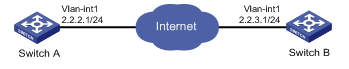
Configuration procedure
1. Configure Switch A:
# Configure an IP address for VLAN-interface 1.
<SwitchA> system-view
[SwitchA] interface vlan-interface 1
[SwitchA-Vlan-interface1] ip address 2.2.2.1 255.255.255.0
[SwitchA-Vlan-interface1] quit
# Define an ACL to identify data flows between Switch A and Switch B.
[SwitchA] acl number 3101
[SwitchA-acl-adv-3101] rule 0 permit ip source 2.2.2.1 0 destination 2.2.3.1 0
[SwitchA-acl-adv-3101] quit
# Create an IPsec transform set named tran1.
[SwitchA] ipsec transform-set tran1
# Specify the encapsulation mode as tunnel.
[SwitchA-ipsec-transform-set-tran1] encapsulation-mode tunnel
# Specify the security protocol as ESP.
[SwitchA-ipsec-transform-set-tran1] protocol esp
# Specify the ESP encryption and authentication algorithms.
[SwitchA-ipsec-transform-set-tran1] esp encryption-algorithm aes-cbc-192
[SwitchA-ipsec-transform-set-tran1] esp authentication-algorithm sha1
[SwitchA-ipsec-transform-set-tran1] quit
# Create a manual IPsec policy entry, with the policy name map1 and sequence number 10.
[SwitchA] ipsec policy map1 10 manual
# Apply ACL 3101.
[SwitchA-ipsec-policy-manual-map1-10] security acl 3101
# Apply the IPsec transform set tran1.
[SwitchA-ipsec-policy-manual-map1-10] transform-set tran1
# Specify the remote IP address of the IPsec tunnel as 2.2.3.1.
[SwitchA-ipsec-policy-manual-map1-10] remote-address 2.2.3.1
# Configure inbound and outbound SPIs for ESP.
[SwitchA-ipsec-policy-manual-map1-10] sa spi outbound esp 12345
[SwitchA-ipsec-policy-manual-map1-10] sa spi inbound esp 54321
# Configure the inbound and outbound SA keys for ESP.
[SwitchA-ipsec-policy-manual-map1-10] sa string-key outbound esp simple abcdefg
[SwitchA-ipsec-policy-manual-map1-10] sa string-key inbound esp simple gfedcba
[SwitchA-ipsec-policy-manual-map1-10] quit
# Apply the IPsec policy map1 to VLAN-interface 1.
[SwitchA] interface vlan-interface 1
[SwitchA-Vlan-interface1] ipsec apply policy map1
2. Configure Switch B:
# Configure an IP address for VLAN-interface 1.
<SwitchB> system-view
[SwitchB] interface vlan-interface 1
[SwitchB-Vlan-interface1] ip address 2.2.3.1 255.255.255.0
[SwitchB-Vlan-interface1] quit
# Define an ACL to identify data flows between Switch B and Switch A.
[SwitchB] acl number 3101
[SwitchB-acl-adv-3101] rule 0 permit ip source 2.2.3.1 0 destination 2.2.2.1 0
[SwitchB-acl-adv-3101] quit
# Create an IPsec transform set named tran1.
[SwitchB] ipsec transform-set tran1
# Specify the encapsulation mode as tunnel.
[SwitchB-ipsec-transform-set-tran1] encapsulation-mode tunnel
# Specify the security protocol as ESP.
[SwitchB-ipsec-transform-set-tran1] protocol esp
# Specify the ESP encryption and authentication algorithms.
[SwitchB-ipsec-transform-set-tran1] esp encryption-algorithm aes-cbc-192
[SwitchB-ipsec-transform-set-tran1] esp authentication-algorithm sha1
[SwitchB-ipsec-transform-set-tran1] quit
# Create a manual IPsec policy entry, with the policy name use1 and sequence number 10.
[SwitchB] ipsec policy use1 10 manual
# Apply ACL 3101.
[SwitchB-ipsec-policy-manual-use1-10] security acl 3101
# Apply IPsec transform set tran1.
[SwitchB-ipsec-policy-manual-use1-10] transform-set tran1
# Specify the remote IP address of the IPsec tunnel as 2.2.2.1.
[SwitchB-ipsec-policy-manual-use1-10] remote-address 2.2.2.1
# Configure the inbound and outbound SPIs for ESP.
[SwitchB-ipsec-policy-manual-use1-10] sa spi outbound esp 54321
[SwitchB-ipsec-policy-manual-use1-10] sa spi inbound esp 12345
# Configure the inbound and outbound SA keys for ESP.
[SwitchB-ipsec-policy-manual-use1-10] sa string-key outbound esp simple gfedcba
[SwitchB-ipsec-policy-manual-use1-10] sa string-key inbound esp simple abcdefg
[SwitchB-ipsec-policy-manual-use1-10] quit
# Apply the IPsec policy use1 to VLAN-interface 1.
[SwitchB] interface vlan-interface 1
[SwitchB-Vlan-interface1] ipsec apply policy use1
Verifying the configuration
After the configuration is completed, an IPsec tunnel between Switch A and Switch B is established, and the traffic between the switches is IPsec protected. This example uses Switch A to verify the configuration.
# Use the display ipsec sa command to display IPsec SAs on Switch A.
[SwitchA] display ipsec sa
-------------------------------
Interface: Vlan-interface 1
-------------------------------
-----------------------------
IPsec policy: map1
Sequence number: 10
Mode: manual
-----------------------------
Tunnel id: 549
Encapsulation mode: tunnel
Path MTU: 1443
Tunnel:
local address: 2.2.2.1
remote address: 2.2.3.1
Flow:
as defined in ACL 3101
[Inbound ESP SA]
SPI: 54321 (0x0000d431)
Transform set: ESP-ENCRYPT-AES-CBC-192 ESP-AUTH-SHA1
No duration limit for this SA
[Outbound ESP SA]
SPI: 12345 (0x00003039)
Transform set: ESP-ENCRYPT-AES-CBC-192 ESP-AUTH-SHA1
No duration limit for this SA
Configuring an IKE-based IPsec tunnel for IPv4 packets
Network requirements
As shown in Figure 29, establish an IPsec tunnel between Switch A and Switch B to protect data flows between the switches. Configure the IPsec tunnel as follows:
· Specify the encapsulation mode as tunnel, the security protocol as ESP, the encryption algorithm as AES-CBC-192, and the authentication algorithm as HMAC-SHA1.
· Set up SAs through IKE negotiation.
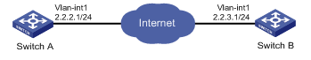
Configuration procedure
1. Configure Switch A:
# Configure an IP address for VLAN-interface 1.
<SwitchA> system-view
[SwitchA] interface vlan-interface 1
[SwitchA-Vlan-interface1] ip address 2.2.2.1 255.255.255.0
[SwitchA-Vlan-interface1] quit
# Define an ACL to identify data flows from Switch A to Switch B.
[SwitchA] acl number 3101
[SwitchA-acl-adv-3101] rule 0 permit ip source 2.2.2.1 0 destination 2.2.3.1 0
[SwitchA-acl-adv-3101] quit
# Create an IPsec transform set named tran1.
[SwitchA] ipsec transform-set tran1
# Specify the encapsulation mode as tunnel.
[SwitchA-ipsec-transform-set-tran1] encapsulation-mode tunnel
# Specify the security protocol as ESP.
[SwitchA-ipsec-transform-set-tran1] protocol esp
# Specify the ESP encryption and authentication algorithms.
[SwitchA-ipsec-transform-set-tran1] esp encryption-algorithm aes-cbc-192
[SwitchA-ipsec-transform-set-tran1] esp authentication-algorithm sha1
[SwitchA-ipsec-transform-set-tran1] quit
# Create the IKE keychain named keychain1.
[SwitchA] ike keychain keychain1
# Configure the pre-shared key used with the peer 2.2.3.1 as plaintext string of 12345zxcvb!@#$%ZXCVB.
[SwitchA-ike-keychain-keychain1] pre-shared-key address 2.2.3.1 255.255.255.0 key simple 12345zxcvb!@#$%ZXCVB
[SwitchA-ike-keychain-keychain1] quit
# Create the IKE profile named profile1.
[SwitchA] ike profile profile1
# Reference the keychain keychain1.
[SwitchA-ike-profile-profile1] keychain keychain1
[SwitchA-ike-profile-profile1] match remote identity address 2.2.3.1 255.255.255.0
[SwitchA-ike-profile-profile1] quit
# Create an IKE-based IPsec policy entry, with the policy name map1 and sequence number 10.
[SwitchA] ipsec policy map1 10 isakmp
# Apply ACL 3101.
[SwitchA-ipsec-policy-isakmp-map1-10] security acl 3101
# Apply the IPsec transform set tran1.
[SwitchA-ipsec-policy-isakmp-map1-10] transform-set tran1
# Specify the local and remote IP addresses of the IPsec tunnel as 2.2.2.1 and 2.2.3.1.
[SwitchA-ipsec-policy-isakmp-map1-10] local-address 2.2.2.1
[SwitchA-ipsec-policy-isakmp-map1-10] remote-address 2.2.3.1
# Apply the IKE profile profile1.
[SwitchA-ipsec-policy-isakmp-map1-10] ike-profile profile1
[SwitchA-ipsec-policy-isakmp-map1-10] quit
# Specify the card in slot 1 to process the traffic for VLAN-interface 1.
[SwitchA] interface vlan-interface 1
[SwitchA-Vlan-interface1] service slot 1
# Apply the IPsec policy map1 to VLAN-interface 1.
[SwitchA-Vlan-interface1] ipsec apply policy map1
2. Configure Switch B:
# Configure an IP address for VLAN-interface 1.
<SwitchB> system-view
[SwitchB] interface vlan-interface 1
[SwitchB-Vlan-interface1] ip address 2.2.3.1 255.255.255.0
[SwitchB-Vlan-interface1] quit
# Define an ACL to identify data flows from Switch B to Switch A.
[SwitchB] acl number 3101
[SwitchB-acl-adv-3101] rule 0 permit ip source 2.2.3.1 0 destination 2.2.2.1 0
[SwitchB-acl-adv-3101] quit
# Create an IPsec transform set named tran1.
[SwitchB] ipsec transform-set tran1
# Specify the encapsulation mode as tunnel.
[SwitchB-ipsec-transform-set-tran1] encapsulation-mode tunnel
# Specify the security protocol as ESP.
[SwitchB-ipsec-transform-set-tran1] protocol esp
# Specify the ESP encryption and authentication algorithms.
[SwitchB-ipsec-transform-set-tran1] esp encryption-algorithm aes-cbc-192
[SwitchB-ipsec-transform-set-tran1] esp authentication-algorithm sha1
[SwitchB-ipsec-transform-set-tran1] quit
# Create the IKE keychain named keychain1.
[SwitchB] ike keychain keychain1
# Configure the pre-shared key used with the peer 2.2.2.1 as plaintext string of 12345zxcvb!@#$%ZXCVB.
[SwitchB-ike-keychain-keychain1] pre-shared-key address 2.2.2.1 255.255.255.0 key simple 12345zxcvb!@#$%ZXCVB
[SwitchB-ike-keychain-keychain1] quit
# Create the IKE profile named profile1.
[SwitchB] ike profile profile1
# Reference the keychain keychain1.
[SwitchB-ike-profile-profile1] keychain keychain1
[SwitchB-ike-profile-profile1] match remote identity address 2.2.2.1 255.255.255.0
[SwitchB-ike-profile-profile1] quit
# Create an IKE mode IPsec policy entry, with the policy name use1, and sequence number 10.
[SwitchB] ipsec policy use1 10 isakmp
# Apply ACL 3101.
[SwitchB-ipsec-policy-isakmp-use1-10] security acl 3101
# Apply the IPsec transform set tran1.
[SwitchB-ipsec-policy-isakmp-use1-10] transform-set tran1
# Specify the local and remote IP addresses of the IPsec tunnel as 2.2.3.1 and 2.2.2.1.
[SwitchB-ipsec-policy-isakmp-use1-10] local-address 2.2.3.1
[SwitchB-ipsec-policy-isakmp-use1-10] remote-address 2.2.2.1
# Apply the IKE profile profile1.
[SwitchB-ipsec-policy-isakmp-use1-10] ike-profile profile1
[SwitchB-ipsec-policy-isakmp-use1-10] quit
# Specify the card in slot 1 to process the traffic for VLAN-interface 1.
[SwitchB] interface vlan-interface 1
[SwitchB-Vlan-interface1] service slot 1
# Apply the IPsec policy use1 to VLAN-interface 1.
[SwitchB-Vlan-interface1] ipsec apply policy use1
Verifying the configuration
After the configuration is completed, IKE negotiation is triggered to set up IPsec SAs when there are end-to-end packets between Switch A and Switch B. After IPsec SAs are successfully negotiated by IKE, the traffic between the two switches is IPsec protected.
Configuring IKE
Unless otherwise specified, the term "IKE" in this chapter refers to IKEv1.
The term "interface" in this chapter collectively refers to Layer 3 interfaces, including VLAN interfaces and Layer 3 Ethernet interfaces. You can set an Ethernet port as a Layer 3 interface by using the port link-mode route command (see Layer 2—LAN Switching Configuration Guide).
Overview
Built on a framework defined by ISAKMP, Internet Key Exchange (IKE) provides automatic key negotiation and SA establishment services for IPsec, dramatically simplifying the configuration and maintenance of IPsec.
IKE provides the following benefits for IPsec:
· Automatically negotiates IPsec parameters.
· Performs DH exchanges to calculate shared keys, making sure each SA has a key that is independent of other keys.
· Automatically negotiates SAs when the sequence number in the AH or ESP header overflows, making sure IPsec can provide the anti-replay service by using the sequence number.
As shown in Figure 30, IKE negotiates SAs for IPsec and transfers the SAs to IPsec, and IPsec uses the SAs to protect IP packets.
Figure 30 Relationship between IKE and IPsec
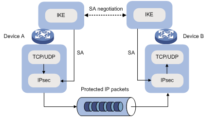
IKE negotiation process
IKE negotiates keys and SAs for IPsec in two phases:
1. Phase 1—The two peers establish an IKE SA, a secure, authenticated channel for communication. In this phase, two modes are available: main mode and aggressive mode.
2. Phase 2—Using the IKE SA established in phase 1, the two peers negotiate to establish IPsec SAs.
Figure 31 IKE exchange process in main mode
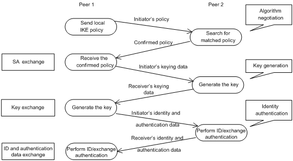
As shown in Figure 31, the main mode of IKE negotiation in phase 1 involves three pairs of messages:
· SA exchange—Used for negotiating the IKE security policy.
· Key exchange—Used for exchanging the DH public value and other values, such as the random number. The two peers use the exchanged data to generate key data and use the encryption key and authentication key to ensure the security of IP packets.
· ID and authentication data exchange—Used for identity authentication.
The main difference between the main mode and the aggressive mode is that the aggressive mode does not provide identity information protection and exchanges only three messages, rather than three pairs. The main mode provides identity information protection but is slower.
IKE security mechanism
IKE has a series of self-protection mechanisms and supports secure identity authentication, key distribution, and IPsec SA establishment on insecure networks.
Identity authentication
The IKE identity authentication mechanism is used to authenticate the identity of the communicating peers. The device supports the following identity authentication methods:
· Pre-shared key authentication—Two communicating peers use the pre-configured shared key for identity authentication.
· RSA signature authentication and DSA signature authentication—Two communicating peers use the digital certificates issued by the CA for identity authentication.
The pre-shared key authentication method does not require certificates and is easy to configure. It is usually deployed in small networks.
The signature authentication methods provide higher security and are usually deployed in networks with the headquarters and branches. When deployed in a network with many branches, a signature authentication method can simplify the configuration because only one PKI domain is required. If you use the pre-shared key authentication method, you must configure a pre-shared key for each branch on the headquarters node.
DH algorithm
The DH algorithm is a public key algorithm. With this algorithm, two peers can exchange keying material and then use the material to calculate the shared keys. Due to the decryption complexity, a third party cannot decrypt the keys even after intercepting all keying materials.
PFS
The Perfect Forward Secrecy (PFS) feature is a security feature based on the DH algorithm. After PFS is enabled, an additional DH exchange is performed in IKE phase 2 to make sure IPsec keys have no derivative relations with IKE keys and a broken key brings no threats to other keys.
Protocols and standards
· RFC 2408, Internet Security Association and Key Management Protocol (ISAKMP)
· RFC 2409, The Internet Key Exchange (IKE)
· RFC 2412, The OAKLEY Key Determination Protocol
IKE configuration prerequisites
Determine the following parameters prior to IKE configuration:
· The algorithms to be used during IKE negotiation, including the identity authentication method, encryption algorithm, authentication algorithm, and DH group.
? Different algorithms provide different levels of protection. A stronger algorithm provides more resistance to decryption but uses more resources.
? A DH group that uses more bits provides higher security but needs more time for processing.
· The pre-shared key or PKI domain for IKE negotiation. For more information about PKI, see "Configuring PKI"
· The IKE-based IPsec policies for the communicating peers. If an IPsec policy does not reference any IKE profile, the device selects an IKE profile for the IPsec policy. If no IKE profile is configured, the globally configured IKE settings are used. For more information about IPsec, see "Configuring IPsec."
IKE configuration task list
|
Tasks at a glance |
Remarks |
|
(Optional.) Configuring an IKE profile |
N/A |
|
(Optional.) Configuring an IKE proposal |
Required when the IKE profile needs to reference IKE proposals. |
|
(Optional.) Configuring an IKE keychain |
Required when pre-shared authentication is used in IKE negotiation phase 1. |
|
(Optional.) Configuring the global identity information |
N/A |
|
(Optional.) Configuring the IKE keepalive feature |
N/A |
|
(Optional.) Configuring the IKE NAT keepalive feature |
N/A |
|
(Optional.) Configuring IKE DPD |
N/A |
|
(Optional.) Enabling invalid SPI recovery |
N/A |
|
(Optional.) Setting the maximum number of IKE SAs |
N/A |
|
(Optional.) Configuring SNMP notifications for IKE |
N/A |
Configuring an IKE profile
An IKE profile is intended to provide a set of parameters for IKE negotiation. To configure an IKE profile, you can do the following:
1. Configure peer IDs. When an end needs to select an IKE profile, it matches the received peer ID against the peer IDs of its local IKE profiles. If a match is found, it uses the IKE profile with the peer ID for IKE negotiation.
2. Configure the IKE keychain or PKI domain for the IKE proposals to use:
? To use digital signature authentication, configure a PKI domain.
? To use pre-shared key authentication, configure an IKE keychain.
3. Specify the negotiation mode (main or aggressive) that the device uses as the initiator. When the device acts as the responder, it uses the IKE negotiation mode of the initiator.
4. Specifies the IKE proposals that the device can use as the initiator. An IKE proposal specified earlier has a higher priority. When the device acts as the responder, it uses the IKE proposals configured in system view to match the IKE proposals received from the initiator. If no match is found, the negotiation fails.
5. Configure the local ID, the ID that the device uses to identify itself to the peer during IKE negotiation:
? For digital signature authentication, the device can use an ID of any type. If the local ID is an IP address that is different from the IP address in the local certificate, the device uses the FQDN (the device name configured by using the sysname command) instead.
? For pre-shared key authentication, the device can use an ID of any type other than the DN.
6. Configure the IKE DPD feature to detect dead IKE peers. You can also configure this feature in system view. The IKE DPD settings configured in the IKE profile takes precedence over those configured in system view.
7. Specify a local interface or IP address for the IKE profile so the profile can be applied only to the specified interface or IP address. For this task, specify the local address configured in IPsec policy view (using the local-address command). If no local address is configured, specify the IP address of the interface that references the IPsec policy.
8. Specify a priority number for the IKE profile. To determine the priority of an IKE profile:
a. The device examines the existence of the match local address command. An IKE profile with the match local address command configured has a higher priority.
b. If a tie exists, the device compares the priority numbers. An IKE profile with a smaller priority number has a higher priority.
c. If a tie still exists, the device prefers an IKE profile configured earlier.
To configure an IKE profile:
|
Step |
Command |
Remarks |
|
1. Enter system view. |
system-view |
N/A |
|
2. Create an IKE profile and enter its view. |
ike profile profile-name |
By default, no IKE profile is configured. |
|
3. Configure a peer ID. |
match remote { certificate policy-name | identity { address { ipv4-address [ mask | mask-length ] | range low-ipv4-address high-ipv4-address } [ vpn-instance vpn-name ] | fqdn fqdn-name | user-fqdn user-fqdn-name } } |
By default, an IKE profile has no peer ID. Each of the two peers must have at least one peer ID configured. |
|
4. Specify the keychain for pre-shared key authentication or specify the PKI domain used to request a certificate for digital signature authentication. |
·
To specify the keychain for pre-shared key authentication: ·
To specify the PKI domain for digital signature authentication: |
Configure either or both commands as required. By default, no IKE keychain or PKI domain is specified for an IKE profile. The certificate domain command is available in Release 1138P01 and later versions. |
|
5. Specify the IKE negotiation mode for phase 1. |
·
In non-FIPS mode: ·
In FIPS mode: |
By default, the main mode is used during IKE negotiation phase 1. |
|
6. Specify the IKE proposals for the IKE profile to reference. |
proposal proposal-number&<1-6> |
By default, an IKE profile references no IKE proposals and uses the IKE proposals configured in system view for IKE negotiation. |
|
7. Configure the local ID. |
local-identity { address ipv4-address | dn | fqdn [ fqdn-name ] | user-fqdn [ user-fqdn-name ] } |
By default, no local ID is configured for an IKE profile, and an IKE profile uses the local ID configured in system view. If the local ID is not configured in system view, the IKE profile uses the IP address of the interface to which the IPsec policy is applied as the local ID. |
|
8. (Optional.) Configure IKE DPD. |
dpd interval interval-seconds [ retry seconds ] { on-demand | periodic } |
By default, the IKE DPD feature is not configured for an IKE profile and an IKE profile uses the DPD settings configured in system view. If the IKE DPD feature is not configured in system either, the device does not perform dead IKE peer detection. |
|
9. (Optional.) Specify the local interface or IP address to which the IKE profile can be applied. |
match local address { interface-type interface-number | ipv4-address [ vpn-instance vpn-name ] } |
By default, an IKE profile can be applied to any local interface or IP address. |
|
10. (Optional.) Specify a priority for the IKE profile. |
priority number |
By default, the priority of an IKE profile is 100. |
Configuring an IKE proposal
An IKE proposal defines a set of attributes describing how IKE negotiation in phase 1 should take place. You can create multiple IKE proposals with different priorities. The priority of an IKE proposal is represented by its sequence number. The lower the sequence number, the higher the priority.
Two peers must have at least one matching IKE proposal for successful IKE negotiation. During IKE negotiation:
· The initiator sends its IKE proposals to the peer.
? If the initiator is using an IPsec policy with an IKE profile, the initiator sends all IKE proposals referenced by the IKE profile to the peer. An IKE proposal specified earlier for the IKE profile has a higher priority.
? If the initiator is using an IPsec policy with no IKE profile, the initiator sends all its IKE proposals to the peer. An IKE proposal with a smaller number has a higher priority.
· The peer searches its own IKE proposals for a match. The search starts from the IKE proposal with the highest priority and proceeds in descending order of priority until a match is found. The matching IKE proposals are used to establish the IKE SA. If all user-defined IKE proposals are found mismatching, the two peers use their default IKE proposals to establish the IKE SA.
Two matching IKE proposals have the same encryption algorithm, authentication method, authentication algorithm, and DH group. The SA lifetime takes the smaller one of the two proposals' SA lifetime settings.
To configure an IKE proposal:
|
Step |
Command |
Remarks |
|
1. Enter system view. |
system-view |
N/A |
|
2. Create an IKE proposal and enter its view. |
ike proposal proposal-number |
By default, there is an IKE proposal that is used as the default IKE proposal. |
|
3. Specify an encryption algorithm for the IKE proposal. |
·
In non-FIPS mode: ·
In FIPS mode: |
By default: · In non-FIPS mode, an IKE proposal uses the 56-bit DES encryption algorithm in CBC mode. · In FIPS mode, an IKE proposal uses the 128-bit AES encryption algorithm in CBC mode. |
|
4. Specify an authentication method for the IKE proposal. |
authentication-method { dsa-signature | pre-share | rsa-signature } |
By default, an IKE proposal uses the pre-shared key authentication method. The dsa-signature and rsa-signature keywords are available in Release 1138P01 and later versions. |
|
5. Specify an authentication algorithm for the IKE proposal. |
·
In non-FIPS mode: ·
In FIPS mode: |
By default, an IKE proposal uses the HMAC-SHA1 authentication algorithm. |
|
6. Specify a DH group for key negotiation in phase 1. |
·
In non-FIPS mode: ·
In FIPS mode: |
By default: · In non-FIPS mode, DH group1 (the 768-bit DH group) is used. · In FIPS mode, DH group14 (the 2048-bit DH group) is used. |
|
7. Set the IKE SA lifetime for the IKE proposal. |
By default, the IKE SA lifetime is 86400 seconds. |
Configuring an IKE keychain
Perform this task when you configure the IKE to use the pre-shared key for authentication.
Follow these guidelines when you configure an IKE keychain:
1. Two peers must be configured with the same pre-shared key to pass pre-shared key authentication.
2. You can specify the local address configured in IPsec policy view (using the local-address command) for the IKE keychain to be applied. If no local address is configured, specify the IP address of the interface that references the IPsec policy.
3. You can specify a priority number for the IKE keychain. To determine the priority of an IKE keychain:
a. The device examines the existence of the match local address command. An IKE keychain with the match local address command configured has a higher priority.
b. If a tie exists, the device compares the priority numbers. An IKE keychain with a smaller priority number has a higher priority.
c. If a tie still exists, the device prefers an IKE keychain configured earlier.
To configure the IKE keychain:
|
Step |
Command |
Remarks |
|
1. Enter system view. |
system-view |
N/A |
|
2. Create an IKE keychain and enter its view. |
ike keychain keychain-name [ vpn-instance vpn-name ] |
By default, no IKE keychain exists. |
|
3. Configure a pre-shared key. |
pre-shared-key { address ipv4-address [ mask | mask-length ] | hostname host-name } key { cipher cipher-key | simple simple-key } |
By default, no pre-shared key is configured. For security purposes, all pre-shared keys, including those configured in plain text, are saved in cipher text to the configuration file. |
|
4. (Optional.) Specify a local interface or IP address to which the IKE keychain can be applied. |
match local address { interface-type interface-number | ipv4-address [ vpn-instance vpn-name ] } |
By default, an IKE keychain can be applied to any local interface or IP address. |
|
5. (Optional.) Specify a priority for the IKE keychain. |
priority number |
The default priority is 100. |
Configuring the global identity information
Follow these guidelines when you configure the global identity information for the local IKE:
· The global identity can be used by the device for all IKE SA negotiations, and the local identity (set by the local-identity command) can be used only by the device that uses the IKE profile.
· When signature authentication is used, you can set any type of the identity information.
· When pre-shared key authentication is used, you cannot set the DN as the identity.
To configure the global identity information:
|
Step |
Command |
Remarks |
|
1. Enter system view. |
system-view |
N/A |
|
2. Configure the global identity to be used by the local end. |
ike identity { address ipv4-address | dn | fqdn [ fqdn-name ] | user-fqdn [ user-fqdn-name ] } |
By default, the IP address of the interface to which the IPsec policy is applied is used as the IKE identity. |
|
3. (Optional.) Configure the local device to always obtain the identity information from the local certificate for signature authentication. |
ike signature-identity from-certificate |
By default, the local end uses the identity information specified by local-identity or ike identity for signature authentication. Configure this command when the aggressive mode and signature authentication are used and the device interconnects with a Comware V5-based peer device. Comware V5 supports only DN for signature authentication. |
Configuring the IKE keepalive feature
IKE sends keepalive packets to query the liveness of the peer. If the peer is configured with the keepalive timeout time, you must configure the keepalive interval on the local device. If the peer receives no keepalive packets during the timeout time, the IKE SA is deleted along with the IPsec SAs it negotiated.
Follow these guidelines when you configure the IKE keepalive feature:
· Configure IKE DPD instead of the IKE keepalive feature unless IKE DPD is not supported on the peer. The IKE keepalive feature sends keepalives at regular intervals, which consumes network bandwidth and resources.
· The keepalive timeout time configured on the local device must be longer than the keepalive interval configured at the peer. Since it seldom occurs that more than three consecutive packets are lost on a network, you can set the keepalive timeout three times as long as the keepalive interval.
To configure the IKE keepalive feature:
|
Step |
Command |
Remarks |
|
1. Enter system view. |
system-view |
N/A |
|
2. Set the IKE SA keepalive interval. |
ike keepalive interval seconds |
By default, no keepalives are sent to the peer. |
|
3. Set the IKE SA keepalive timeout time. |
ike keepalive timeout seconds |
By default, IKE SA keepalive never times out. |
Configuring the IKE NAT keepalive feature
If IPsec traffic passes through a NAT device, you must configure the NAT traversal feature. If no packet travels across an IPsec tunnel in a period of time, the NAT sessions are aged and deleted, disabling the tunnel from transmitting data to the intended end. To prevent NAT sessions from being aged, configure the NAT keepalive feature on the IKE gateway behind the NAT device to send NAT keepalive packets to its peer periodically to keep the NAT session alive.
To configure the IKE NAT keepalive feature:
|
Step |
Command |
Remarks |
|
1. Enter system view. |
system-view |
N/A |
|
2. Set the IKE NAT keepalive interval. |
ike nat-keepalive seconds |
The default interval is 20 seconds. |
Configuring IKE DPD
DPD detects dead peers. It can operate in periodic mode or on-demand mode.
· Periodic DPD—Sends a DPD message at regular intervals. It features an earlier detection of dead peers, but consumes more bandwidth and CPU.
· On-demand DPD—Sends a DPD message based on traffic. When the device has traffic to send and is not aware of the liveness of the peer, it sends a DPD message to query the status of the peer. If the device has no traffic to send, it never sends DPD messages. As a best practice, use the on-demand mode.
The IKE DPD works as follows:
1. The local device sends a DPD message to the peer, and waits for a response from the peer.
2. If the peer does not respond within the retry interval specified by the retry seconds parameter, the local device resends the message.
3. If still no response is received within the retry interval, the local end sends the DPD message again. The system allows a maximum of two retries.
4. If the local device receives no response after two retries, the device considers the peer to be dead, and deletes the IKE SA along with the IPsec SAs it negotiated.
5. If the local device receives a response from the peer during the detection process, the peer is considered alive. The local device performs a DPD detection again when the triggering interval is reached or it has traffic to send, depending on the DPD mode.
Follow these guidelines when you configure the IKE DPD feature:
· When DPD settings are configured in both IKE profile view and system view, the DPD settings in IKE profile view apply. If DPD is not configured in IKE profile view, the DPD settings in system view apply.
· It is a good practice to set the triggering interval longer than the retry interval so that a DPD detection is not triggered during a DPD retry.
To configure IKE DPD:
|
Step |
Command |
Remarks |
|
1. Enter system view. |
system-view |
N/A |
|
2. Enable sending IKE DPD messages. |
ike dpd interval interval-seconds [ retry seconds ] { on-demand | periodic } |
By default, IKE DPD is disabled. |
Enabling invalid SPI recovery
An IPsec "black hole" occurs when one IPsec peer fails (for example, a peer can fail if a reboot occurs). One peer fails and loses its SAs with the other peer. When an IPsec peer receives a data packet for which it cannot find an SA, an invalid SPI is encountered. The peer drops the data packet and tries to send an SPI invalid notification to the data originator. This notification is sent by using the IKE SA. Because no IKE SA is available, the notification is not sent. The originating peer continues sending the data by using the IPsec SA that has the invalid SPI, and the receiving peer keeps dropping the traffic.
The invalid SPI recovery feature enables the receiving peer to set up an IKE SA with the originator so that an SPI invalid notification can be sent. Upon receiving the notification, the originating peer deletes the IPsec SA that has the invalid SPI. If the originator has data to send, new SAs will be set up.
Use caution when you enable the invalid SPI recovery feature because using this feature can result in a DoS attack. Attackers can make a great number of invalid SPI notifications to the same peer.
To enable invalid SPI recovery:
|
Step |
Command |
Remarks |
|
1. Enter system view. |
system-view |
N/A |
|
2. Enable invalid SPI recovery. |
ike invalid-spi-recovery enable |
By default, the invalid SPI recovery is disabled. |
Setting the maximum number of IKE SAs
You can set the maximum number of half-open IKE SAs and the maximum number of established IKE SAs.
· The supported maximum number of half-open IKE SAs depends on the device's processing capability. Adjust the maximum number of half-open IKE SAs to make full use of the device's processing capability without affecting the IKE SA negotiation efficiency.
· The supported maximum number of established IKE SAs depends on the device's memory space. Adjust the maximum number of established IKE SAs to make full use of the device's memory space without affecting other applications in the system.
To set the limit on the number of IKE SAs:
|
Step |
Command |
Remarks |
|
1. Enter system view. |
system-view |
N/A |
|
2. Set the maximum number of half-open IKE SAs and the maximum number of established IKE SAs. |
ike limit { max-negotiating-sa negotiation-limit | max-sa sa-limit } |
By default, there is no limit to the maximum number of IKE SAs. |
Configuring SNMP notifications for IKE
After you enable SNMP notifications for IKE, the IKE module notifies the NMS of important module events. The notifications are sent to the device's SNMP module. You can configure the notification transmission parameters for the SNMP module to specify how the SNMP module displays notifications. For more information about SNMP notifications, see Network Management and Monitoring Configuration Guide.
To generate and output SNMP notifications for IKE for a specific failure type or event type, enable SNMP notifications for IKE globally and for the specified type of failures or events.
To configure SNMP notifications for IKE:
|
Step |
Command |
Remarks |
|
1. Enter system view |
system-view |
N/A |
|
2. Enable SNMP notifications for IKE globally. |
snmp-agent trap enable ike global |
By default, SNMP notifications for IKE are enabled. |
|
3. Enable SNMP notifications for the specified failure type or event type. |
snmp-agent trap enable ike [ attr-not-support | auth-failure | cert-type-unsupport | cert-unavailable | decrypt-failure | encrypt-failure | invalid-cert-auth | invalid-cookie | invalid-id | invalid-proposal | invalid-protocol | invalid-sign | no-sa-failure | proposal-add | proposal–delete | tunnel-start | tunnel-stop | unsupport-exch-type ] * |
By default, SNMP notifications for all failure types and event types are enabled. |
Displaying and maintaining IKE
Execute display commands in any view and reset commands in user view.
|
Task |
Command |
|
Display configuration information about all IKE proposals. |
display ike proposal |
|
Display information about the current IKE SAs. |
display ike sa [ verbose [ connection-id connection-id | remote-address remote-address [ vpn-instance vpn-name ] ] ] |
|
Delete IKE SAs. |
reset ike sa [ connection-id connection-id ] |
|
Clear IKE statistics. |
reset ike statistics |
Main mode IKE with pre-shared key authentication configuration example
Network requirements
As shown in Figure 32, configure an IPsec tunnel that uses IKE negotiation between Switch A and Switch B to secure the communication.
Configure Switch A and Switch B to use the default IKE proposal for the IKE negotiation to set up the IPsec SA. Configure the two switches to use the pre-shared key authentication method.
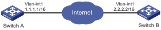
Configuration procedure
Make sure Switch A and Switch B can reach each other.
1. Configure Switch A:
# Assign an IP address to VLAN-interface 1.
<SwitchA> system-view
[SwitchA] interface vlan-interface 1
[SwitchA-vlan-interface1] ip address 1.1.1.1 255.255.0.0
[SwitchA-vlan-interface1] quit
# Configure ACL 3101 to identify traffic between Switch A and Switch B.
[SwitchA] acl number 3101
[SwitchA-acl-adv-3101] rule 0 permit ip source 1.1.1.1 0 destination 2.2.2.2 0
[SwitchA-acl-adv-3101] quit
# Create IPsec transform set tran1.
[SwitchA] ipsec transform-set tran1
# Set the packet encapsulation mode to tunnel.
[SwitchA-ipsec-transform-set-tran1] encapsulation-mode tunnel
# Use the ESP protocol for the IPsec transform set.
[SwitchA-ipsec-transform-set-tran1] protocol esp
# Specify the encryption and authentication algorithms.
[SwitchA-ipsec-transform-set-tran1] esp encryption-algorithm aes-cbc-192
[SwitchA-ipsec-transform-set-tran1] esp authentication-algorithm sha1
[SwitchA-ipsec-transform-set-tran1] quit
# Create IKE keychain keychain1.
[SwitchA] ike keychain keychain1
# Specify 12345zxcvb!@#$%ZXCVB as the plaintext pre-shared key.
[SwitchA-ike-keychain-keychain1] pre-shared-key address 2.2.2.2 255.255.0.0 key simple 12345zxcvb!@#$%ZXCVB
[SwitchA-ike-keychain-keychain1] quit
# Create IKE profile profile1.
[SwitchA] ike profile profile1
# Specify IKE keychain keychain1.
[SwitchA-ike-profile-profile1] keychain keychain1
# Configure a peer ID with the identity type of IP address and the value of 2.2.2.2/16.
[SwitchA-ike-profile-profile1] match remote identity address 2.2.2.2 255.255.0.0
[SwitchA-ike-profile-profile1] quit
# Create an IPsec policy entry, and specify the IPsec policy name as map1, the sequence number as 10, and the IPsec SA setup mode as IKE.
[SwitchA] ipsec policy map1 10 isakmp
# Specify the remote IP address 2.2.2.2 for the IPsec tunnel.
[SwitchA-ipsec-policy-isakmp-map1-10] remote-address 2.2.2.2
# Reference ACL 3101 to identify the traffic to be protected.
[SwitchA-ipsec-policy-isakmp-map1-10] security acl 3101
# Reference IPsec transform set tran1 for the IPsec policy.
[SwitchA-ipsec-policy-isakmp-map1-10] transform-set tran1
# Specify IKE profile profile1 for the IPsec policy.
[SwitchA-ipsec-policy-isakmp-map1-10] ike-profile profile1
[SwitchA-ipsec-policy-isakmp-map1-10] quit
# Specify the card in slot 1 to forward the traffic for VLAN-interface 1.
[SwitchA] interface vlan-interface 1
[SwitchA-Vlan-interface1] service slot 1
# Apply IPsec policy map1 to VLAN-interface 1.
[SwitchA-Vlan-interface1] ipsec apply policy map1
2. Configure Device B:
# Assign an IP address to VLAN-interface 1.
<SwitchB> system-view
[SwitchB] interface Vlan-interface1
[SwitchB-Vlan-interface1] ip address 2.2.2.2 255.255.0.0
[SwitchB-Vlan-interface1] quit
# Configure ACL 3101 to identify traffic between Switch B and Switch A.
[SwitchB] acl number 3101
[SwitchB-acl-adv-3101] rule 0 permit ip source 2.2.2.2 0 destination 1.1.1.0 0
[SwitchB-acl-adv-3101] quit
# Create IPsec transform set tran1.
[SwitchB] ipsec transform-set tran1
# Set the packet encapsulation mode to tunnel.
[SwitchB-ipsec-transform-set-tran1] encapsulation-mode tunnel
# Use the ESP protocol for the IPsec transform set.
[SwitchB-ipsec-transform-set-tran1] protocol esp
# Specify the encryption and authentication algorithms.
[SwitchB-ipsec-transform-set-tran1] esp encryption-algorithm aes-cbc-192
[SwitchB-ipsec-transform-set-tran1] esp authentication-algorithm sha1
[SwitchB-ipsec-transform-set-tran1] quit
# Create IKE keychain keychain1.
[SwitchB]ike keychain keychain1
# Specify the plaintext 12345zxcvb!@#$%ZXCVB as the pre-shared key to be used with the remote peer at 1.1.1.1.
[SwitchB-ike-keychain-keychain1] pre-shared-key address 1.1.1.1 255.255.0.0 key simple 12345zxcvb!@#$%ZXCVB
[SwitchB-ike-keychain-keychain1] quit
# Create IKE profile profile1.
[SwitchB] ike profile profile1
# Specify IKE keychain keychain1
[SwitchB-ike-profile-profile1] keychain keychain1
# Configure a peer ID with the identity type of IP address and the value of 1.1.1.1/16.
[SwitchB-ike-profile-profile1] match remote identity address 1.1.1.1 255.255.0.0
[SwitchB-ike-profile-profile1] quit
# Create an IPsec policy entry, and specify the IPsec policy name as use1, the sequence number as 10, and the IPsec SA setup mode as IKE.
[SwitchB] ipsec policy use1 10 isakmp
# Specify the remote IP address 1.1.1.1 for the IPsec tunnel.
[SwitchB-ipsec-policy-isakmp-use1-10] remote-address 1.1.1.1
# Reference ACL 3101 to identify the traffic to be protected.
[SwitchB-ipsec-policy-isakmp-use1-10] security acl 3101
# Reference IPsec transform set tran1 for the IPsec policy.
[SwitchB-ipsec-policy-isakmp-use1-10] transform-set tran1
# Specify IKE profile profile1 for the IPsec policy.
[SwitchB-ipsec-policy-isakmp-use1-10] ike-profile profile1
[SwitchB-ipsec-policy-isakmp-use1-10] quit
# Specify the card in slot 1 to forward the traffic for VLAN-interface 1.
[SwitchB] interface vlan-interface 1
[SwitchB-Vlan-interface1] service slot 1
# Apply IPsec policy use1 to VLAN-interface 1.
[SwitchB-Vlan-interface1] ipsec apply policy use1
Verifying the configuration
When there is traffic between Switch A and Switch B, IKE negotiation is triggered.
Troubleshooting IKE
IKE negotiation failed because no matching IKE proposals were found
Symptom
1. The IKE SA is in Unknown state.
<Sysname> display ike sa
Connection-ID Remote Flag DOI
------------------------------------------------------------------
1 192.168.222.5 Unknown IPSEC
Flags:
RD--READY RL--REPLACED FD-FADING
2. When IKE event debugging and packet debugging are enabled, the following messages appear:
IKE event debugging message:
The attributes are unacceptable.
IKE packet debugging message:
Construct notification packet: NO_PROPOSAL_CHOSEN.
Analysis
Certain IKE proposal settings are incorrect.
Solution
1. Examine the IKE proposal configuration to see whether the two ends have matching IKE proposals.
2. Modify the IKE proposal configuration to make sure the two ends have matching IKE proposals.
IKE negotiation failed because no IKE proposals or IKE keychains are referenced correctly
Symptom
1. The IKE SA is in Unknown state.
<Sysname> display ike sa
Connection-ID Remote Flag DOI
------------------------------------------------------------------
1 192.168.222.5 Unknown IPSEC
Flags:
RD--READY RL--REPLACED FD-FADING
2. The following IKE event debugging or packet debugging message appeared:
IKE event debugging message:
Notification PAYLOAD_MALFORMED is received.
IKE packet debugging message:
Construct notification packet: PAYLOAD_MALFORMED.
Analysis
· If the following debugging information appeared, the matched IKE profile is not referencing the matched IKE proposal:
Failed to find proposal 1 in profile profile1.
· If the following debugging information appeared, the matched IKE profile is not referencing the matched IKE keychain:
Failed to find keychain keychain1 in profile profile1.
Solution
· Verify that the matched IKE proposal (IKE proposal 1 in this debugging message example) is referenced by the IKE profile (IKE profile 1 in the example).
· Verify that the matched IKE keychain (IKE keychain 1 in this debugging message example) is referenced by the IKE profile (IKE profile 1 in the example).
IPsec SA negotiation failed because no matching IPsec transform sets were found
Symptom
1. The display ike sa command shows that the IKE SA negotiation succeeded and the IKE SA is in RD state, but the display ipsec sa command shows that the expected IPsec SA has not been negotiated yet.
2. The following IKE debugging message appeared:
The attributes are unacceptable.
Or:
Construct notification packet: NO_PROPOSAL_CHOSEN.
Analysis
Certain IPsec policy settings are incorrect.
Solution
1. Examine the IPsec configuration to see whether the two ends have matching IPsec transform sets.
2. Modify the IPsec configuration to make sure the two ends have matching IPsec transform sets.
IPsec SA negotiation failed due to invalid identity information
Symptom
1. The display ike sa command shows that the IKE SA negotiation succeeded and the IKE SA is in RD state, but the display ipsec sa command shows that the expected IPsec SA has not been negotiated yet.
2. The following IKE debugging message appeared:
Notification INVALID_ID_INFORMATION is received.
Or:
Failed to get IPsec policy when renegotiating IPsec SA. Delete IPsec SA.
Construct notification packet: INVALID_ID_INFORMATION.
Analysis
Certain IPsec policy settings of the responder are incorrect. Verify the settings as follows:
1. Use the display ike sa verbose command to verify that matching IKE profiles were found in IKE negotiation phase 1. If no matching IKE profiles were found and the IPsec policy is referencing an IKE profile, the IPsec SA negotiation fails.
# Verify that matching IKE profiles were found in IKE negotiation phase 1.
<Sysname> display ike sa verbose
-----------------------------------------------
Connection ID: 3
Outside VPN:
Inside VPN:
Profile:
Transmitting entity: Responder
-----------------------------------------------
Local IP: 192.168.222.5
Local ID type: IPV4_ADDR
Local ID: 192.168.222.5
Remote IP: 192.168.222.71
Remote ID type: IPV4_ADDR
Remote ID: 192.168.222.71
Authentication-method: PRE-SHARED-KEY
Authentication-algorithm: MD5
Encryption-algorithm: 3DES-CBC
Life duration(sec): 86400
Remaining key duration(sec): 85847
Exchange-mode: Main
Diffie-Hellman group: Group 1
NAT traversal: Not detected
# Verify that the IPsec policy is referencing an IKE profile.
[Sysname] display ipsec policy
-------------------------------------------
IPsec Policy: policy1
Interface: Vlan-interface1
-------------------------------------------
-----------------------------
Sequence number: 1
Mode: isakmp
-----------------------------
Description:
Security data flow: 3000
Selector mode: aggregation
Local address: 192.168.222.5
Remote address: 192.168.222.71
Transform set: transform1
IKE profile: profile1
SA duration(time based):
SA duration(traffic based):
SA idle time:
2. Verify that the ACL referenced by the IPsec policy is correctly configured. If the flow range defined by the responder's ACL is smaller than that defined by the initiator's ACL, IPsec proposal matching will fail.
For example, if the initiator's ACL defines a flow from one network segment to another but the responder's ACL defines a flow from one host to another host, IPsec proposal matching will fail.
# On the initiator:
[Sysname] display acl 3000
Advanced ACL 3000, named -none-, 2 rules,
ACL's step is 5
rule 0 permit ip source 192.168.222.0 0.0.0.255 destination 192.168.222.0 0.0.0.255
# On the responder:
[Sysname] display acl 3000
Advanced ACL 3000, named -none-, 2 rules,
ACL's step is 5
rule 0 permit ip source 192.168.222.71 0 destination 192.168.222.5 0
3. Verify that the IPsec policy has a remote address and an IPsec transform set configured and that the IPsec transform set has all necessary settings configured.
If, for example, the IPsec policy has no remote address configured, the IPsec SA negotiation will fail:
[Sysname] display ipsec policy
-------------------------------------------
IPsec Policy: policy1
Interface: Vlan-interface1
-------------------------------------------
-----------------------------
Sequence number: 1
Mode: isakmp
-----------------------------
Description:
Security data flow: 3000
Selector mode: aggregation
Local address: 192.168.222.5
Remote address:
Transform set: transform1
IKE profile: profile1
SA duration(time based):
SA duration(traffic based):
SA idle time:
Solution
1. If no matching IKE profiles were found and the IPsec policy is referencing an IKE profile, remove the reference.
2. If the flow range defined by the responder's ACL is smaller than that defined by the initiator's ACL, modify the responder's ACL so the ACL defines a flow range equal to or greater than that of the initiator's ACL.
For example:
[Sysname] display acl 3000
Advanced ACL 3000, named -none-, 2 rules,
ACL's step is 5
rule 0 permit ip source 192.168.222.0 0.0.0.255 destination 192.168.222.0 0.0.0.255
3. Configure the missing settings (for example, the remote address).
Configuring SSH
Overview
Secure Shell (SSH) is a network security protocol. Using encryption and authentication, SSH can implement secure remote access and file transfer over an insecure network. Adopting the typical client/server model, SSH can establish a channel to protect data transfer based on TCP.
SSH includes two versions: SSH1.x and SSH2.0 (hereinafter referred to as SSH1 and SSH2), which are not compatible. SSH2 is better than SSH1 in performance and security.
The device can work as an SSH server or as an SSH client.
· When acting as an SSH server, the device provides services for SSH clients and supports the following SSH versions:
? For Secure Telnet (Stelnet), Secure File Transfer Protocol (SFTP), or Secure Copy (SCP) connections, the device supports the following SSH versions:
- SSH2 and SSH1 in non-FIPS mode.
- SSH2 in FIPS mode.
? For NETCONF-over-SSH connections, the device supports only SSH2 in both non-FIPS and FIPS modes.
· When acting as an SSH client, the device supports SSH2 only. It allows users to establish SSH connections with an SSH server.
The device supports the following SSH applications:
· Stelnet—Stelnet provides secure and reliable network terminal access services. Through Stelnet, a user can securely log in to a remote server. Stelnet can protect devices against attacks, such as IP spoofing and plain text password interception. The device can act as an Stelnet server or an Stelnet client.
· SFTP—Based on SSH2, it uses SSH connections to provide secure file transfer. The device can serve as an SFTP server, allowing a remote user to log in to the SFTP server for secure file management and transfer. The device can also serve as an SFTP client, enabling a user to log in from the device to a remote device for secure file transfer.
· SCP—Based on SSH2, it offers a secure approach to copying files. The device can act as an SCP server, allowing a user to log in to the device for file upload and download. The device can also act as an SCP client, enabling a user to log in from the device to a remote device for secure file transfer.
· NETCONF over SSH—Based on SSH2, it enables users to securely log in to the device through SSH and perform NETCONF operations on the device through NETCONF-over-SSH connections. The device can act only as a server in NETCONF-over-SSH connections. For more information about NETCONF, see Network Management and Monitoring Configuration Guide.
How SSH works
This section uses SSH2 as an example to list the stages involved in secure session establishment between an SSH client and an SSH server. For more information about these stages, see SSH Technology White Paper.
Table 7 Stages involved in secure session establishment
|
Stages |
Description |
|
Connection establishment |
The SSH server listens to the connection requests on port 22. After a client initiates a connection request, the server and the client establish a TCP connection. |
|
Version negotiation |
The two parties determine a version to use after negotiation. |
|
Algorithm negotiation |
SSH supports multiple algorithms. Based on the local algorithms, the two parties negotiate the following algorithms: · Key exchange algorithm for generating session keys. · Encryption algorithm for encrypting data. · Public key algorithm for digital signature and authentication. · HMAC algorithm for protecting data integrity. |
|
Key exchange |
The two parties use the DH exchange algorithm to dynamically generate the session keys and the session ID. · The session keys are used for protecting data transfer. · The session ID is used for identifying the SSH connection. In this stage, the client also authenticates the server. |
|
Authentication |
The SSH server authenticates the client in response to the client's authentication request. |
|
Session request |
After passing the authentication, the client sends a session request to the server to request the establishment of a session (or request the Stelnet, SFTP, SCP, or NETCONF service). |
|
Interaction |
After the server grants the request, the client and the server start to communicate with each other in the session. In this stage, you can paste commands in text format and execute them at the CLI. The text pasted at one time must be no more than 2000 bytes. As a best practice to ensure correct command execution, paste commands that are in the same view. To execute commands of more than 2000 bytes, save the commands in a configuration file, upload the file to the server through SFTP, and use it to restart the server. |
SSH authentication methods
This section describes authentication methods that are supported by the device when it acts as an SSH server.
Password authentication
The SSH server authenticates a client through the AAA mechanism. The password authentication process is as follows:
1. The client sends the server an authentication request that includes the encrypted username and password.
2. The server performs the following operations:
a. Decrypts the request to get the username and password in plain text.
b. Verifies the username and password locally or through remote AAA authentication.
c. Informs the client of the authentication result.
If the remote AAA server requires the user to enter a password for secondary authentication, it send the SSH server an authentication response carrying a prompt. The prompt is transparently transmitted to the client to notify the user to enter a specific password. After the user enters the correct password and passes validity check by the remote AAA server, the SSH server returns an authentication success message to the client.
For more information about AAA, see "Configuring AAA"
|
|
NOTE: SSH1 clients do not support secondary password authentication that is initiated by the AAA server. |
Publickey authentication
The server authenticates a client by verifying the digital signature of the client. The publickey authentication process is as follows:
1. The client sends the server a publickey authentication request that includes the username, public key, and public key algorithm name.
2. The server verifies the client's public key.
? If the public key is invalid, the server informs the client of the authentication failure.
? If the public key is valid, the server requests the digital signature of the client. After receiving the signature, the server uses the public key to verify the signature and informs the client of the authentication result.
When acting as an SSH server, the device supports using the public key algorithms DSA and RSA to verify digital signatures.
When acting as an SSH client, the device supports using the public key algorithms DSA and RSA to generate digital signatures.
For more information about public key configuration, see "Managing public keys"
Password-publickey authentication
The server requires SSH2 clients to pass both password authentication and publickey authentication. However, an SSH1 client only needs to pass either authentication.
Any authentication
The server requires clients to pass either password authentication or publickey authentication.
FIPS compliance
The device supports the FIPS mode that complies with NIST FIPS 140-2 requirements. Support for features, commands, and parameters might differ in FIPS mode and non-FIPS mode. For more information about FIPS mode, see "Configuring FIPS"
Configuring the device as an SSH server
SSH server configuration task list
|
Tasks at a glance |
Remarks |
|
(Optional.) Generating local DSA or RSA key pairs |
N/A |
|
(Required.) Enabling the Stelnet server |
Required for Stelnet servers. |
|
(Required.) Enabling the SFTP server |
Required for SFTP servers. |
|
(Required.) Enabling the SCP server |
Required for SCP servers. |
|
(Required.) Configuring NETCONF over SSH |
Required for NETCONF-over-SSH servers. |
|
(Required.) Configuring user lines for SSH login |
Required for the Stelnet clients and NETCONF-over-SSH clients. |
|
(Required.) Configuring a client's host public key |
Required if the authentication method is publickey, password-publickey, or any. |
|
(Required/optional.) Configuring an SSH user |
Required if the authentication method is publickey, password-publickey, or any. Optional if the authentication method is password. |
|
(Optional.) Setting the SSH management parameters |
N/A |
Generating local DSA or RSA key pairs
|
|
IMPORTANT: Do not generate the local DSA key pair when the device operates in FIPS mode as an SSH server. User authentication will fail because the SSH server operating in FIPS mode supports only RSA key pairs. |
The DSA or RSA key pairs are required for generating the session key and session ID in the key exchange stage, and can also be used by a client to authenticate the server. When a client tries to authenticate the server, it compares the public key that it receives from the server with the server public key that it saved locally. If the keys are consistent, the client uses the locally saved server's public key to decrypt the digital signature received from the server. If the decryption succeeds, the server passes the authentication.
When you execute any of the SSH commands on the device to trigger the running of the SSH application, the SSH server automatically generates two RSA key pairs. You can also use the public-key local create command to generate DSA and RSA key pairs on the device.
Configuration guidelines
When you generate local DSA or RSA key pairs, follow these restrictions and guidelines:
· SSH supports only locally generated DSA and RSA key pairs with default names.
· To support SSH clients that use different types of key pairs, generate both DSA and RSA key pairs on the SSH server.
· The public-key local create rsa command generates a server key pair and a host key pair for RSA. SSH1 uses the public key in the server key pair of the SSH server to encrypt the session key before transmitting the session key. Because SSH2 uses the DH algorithm to separately generate the session key on the SSH server and the client, no session key transmission is required. The server key pair is not used in SSH2.
· The public-key local create dsa command generates only a host key pair. SSH1 does not support the DSA algorithm.
· The key modulus length must be less than 2048 bits when you generate the DSA key pair on the SSH server.
Configuration procedure
To generate local DSA or RSA key pairs on the SSH server:
|
Step |
Command |
Remarks |
|
1. Enter system view. |
system-view |
N/A |
|
2. Generate local DSA or RSA key pairs. |
public-key local create { dsa | rsa } |
By default, no key pairs exist. |
Enabling the Stelnet server
After you enable the Stelnet server on the device, a client can log in to the device through Stelnet.
To enable the Stelnet server:
|
Step |
Command |
Remarks |
|
1. Enter system view. |
system-view |
N/A |
|
2. Enable the Stelnet server. |
ssh server enable |
By default, the Stelnet server is disabled. |
Enabling the SFTP server
After you enable the SFTP server on the device, a client can log in to the device through SFTP.
When acting as an SFTP server, the device does not support SFTP connections initiated by SSH1 clients.
To enable the SFTP server:
|
Step |
Command |
Remarks |
|
1. Enter system view. |
system-view |
N/A |
|
2. Enable the SFTP server. |
sftp server enable |
By default, the SFTP server is disabled. |
Enabling the SCP server
After you enable the SCP server on the device, a client can log in to the device through SCP.
When acting as an SCP server, the device does not support SCP connections initiated by SSH1 clients.
To enable the SCP server:
|
Step |
Command |
Remarks |
|
1. Enter system view. |
system-view |
N/A |
|
2. Enable the SCP server. |
By default, the SCP server is disabled. |
Configuring NETCONF over SSH
This feature allows users to use a client to perform NETCONF operations on the device through a NETCONF-over-SSH connection.
When acting as a server in the NETCONF-over-SSH connection, the device does not support connection requests initiated by SSH1 clients.
For more information about NETCONF over SSH commands, see Network Management and Monitoring Command Reference.
To configure NETCONF over SSH:
|
Step |
Command |
Remark |
|
1. Enter system view. |
system-view |
N/A |
|
2. Enable NETCONF over SSH. |
By default, NETCONF over SSH is disabled. |
|
|
3. Specify a port to listen for NETCONF-over-SSH connections. |
netconf ssh server port port-number |
By default, port 830 listens for NETCONF-over-SSH connections. |
Configuring user lines for SSH login
Depending on SSH applications, an SSH client can be an Stelnet client, SFTP client, SCP client, or NETCONF-over-SSH client.
Only Stelnet and NETCONF-over-SSH clients require the user line configuration. The user line configuration takes effect on only the clients at the next login.
To configure the user lines for Stelnet and NETCONF-over-SSH clients:
|
Step |
Command |
Remarks |
|
1. Enter system view. |
system-view |
N/A |
|
2. Enter VTY user line view. |
line vty number [ ending-number ] |
N/A |
|
3. Set the login authentication mode to scheme. |
authentication-mode scheme |
By default, the authentication mode is password. For more information about this command, see Fundamentals Command Reference. |
Configuring a client's host public key
If the server uses publickey authentication to authentication a client, it compares the SSH username and host public key that it receives from the client with those locally saved. If the information is consistent, it checks the digital signature that the client sends. The digital signature is generated by the client according to the private key that corresponds to the host public key.
For publickey authentication, password-publickey authentication, or any authentication, you must perform the following tasks:
1. Configure the client's DSA or RSA host public key on the server.
As a best practice, configure no more than 20 SSH client host public keys on an SSH server.
2. Specify the associated host private key on the client to generate the digital signature.
If the device serves as a client, specify the public key algorithm on the client. The algorithm determines the associated host private key for generating the digital signature.
You can enter the content of a client's host public key or import the client's host public key from the public key file. As a best practice, import the client's host public key.
Entering a client's host public key
Before you enter the client's host public key, you must use the display public-key local public command on the client to obtain the client's host public key.
To enter a client's host public key:
|
Step |
Command |
Remarks |
|
1. Enter system view. |
system-view |
N/A |
|
2. Enter public key view. |
public-key peer keyname |
N/A |
|
3. Configure a client's host public key. |
Enter the content of the host public key |
The host public key must be in the DER encoding format without being converted. When you enter the contents for a host public key, you can use spaces and carriage returns between characters. When you save the host public key, spaces and carriage returns are removed automatically. For more information, see "Managing public keys" |
|
4. Return to system view. |
peer-public-key end |
N/A |
Importing a client's host public key from the public key file
Before you import the host public key, upload the client's public key file (in binary) to the server, for example, through FTP or TFTP. During the import process, the server automatically converts the host public key in the public key file to a string in PKCS format.
To import a client's host public key from a public key file:
|
Step |
Command |
|
1. Enter system view. |
system-view |
|
2. Import a client's public key from a public key file. |
public-key peer keyname import sshkey filename |
Configuring an SSH user
Configure an SSH user and local user depending on the authentication method:
· If the authentication method is publickey, you must create an SSH user and a local user on the SSH server. The two users must have the same username, so that the SSH user can be assigned the correct working directory and user role.
· If the authentication method is password, you must perform one of the following tasks:
? For local authentication, configure a local user on the SSH server.
? For remote authentication, configure an SSH user on a remote authentication server, for example, a RADIUS server.
You do not need to create an SSH user by using the ssh user command. However, if you want to display all SSH users, including the password-only SSH users, for centralized management, you can use this command to create them. If such an SSH user has been created, make sure you have specified the correct service type and authentication method.
· If the authentication method is password-publickey or any, you must create an SSH user on the SSH server and perform one of the following tasks:
? For local authentication, configure a local user on the SSH server.
? For remote authentication, configure an SSH user on a remote authentication server, for example, a RADIUS server.
In either case, the local user or the SSH user configured for remote authentication must have the same username as the SSH user.
Configuration guidelines
When you configure an SSH user, follow these restrictions and guidelines:
· An SSH server supports up to 1024 SSH users.
· For an SFTP or SCP user, the working directory depends on the authentication method:
? If the authentication method is password, the working directory is authorized by AAA.
? If the authentication method is publickey or password-publickey, the working folder is specified by the authorization-attribute command in the associated local user view.
· For an SSH user, the user role also depends on the authentication method:
? If the authentication method is password, the user role is authorized by the remote AAA server or the local device.
? If the authentication method is publickey or password-publickey, the user role is specified by the authorization-attribute command in the associated local user view.
· If you change the authentication method or public key for an SSH user that has been logged in, the change can take effect on only the user at the next login.
· Except password authentication, the other authentication methods require a client's host public key to be specified. For more information about host public keys, see "Configuring a client's host public key."
· When the device operates in FIPS mode as an SSH server, the device does not support the authentication method of any or publickey.
For information about configuring local users and remote authentication, see "Configuring AAA"
Configuration procedure
To configure an SSH user, and specify the service type and authentication method:
|
Step |
Command |
|
1. Enter system view. |
system-view |
|
2. Create an SSH user, and specify the service type and authentication method. |
·
In non-FIPS mode: ·
In non-FIPS mode: |
Setting the SSH management parameters
|
Command |
Remarks |
|
|
1. Enter system view. |
system-view |
N/A |
|
2. Enable the SSH server to support SSH1 clients. |
ssh server compatible-ssh1x enable |
By default, the SSH server supports SSH1 clients. This command is not available in FIPS mode. |
|
3. Set the RSA server key pair update interval. |
ssh server rekey-interval hours |
By default, the RSA server key pair is not updated. This command takes effect on only SSH1 users. This command is not available in FIPS mode. |
|
4. Set the SSH user authentication timeout period. |
ssh server authentication-timeout time-out-value |
The default setting is 60 seconds. If a user does not finish the authentication when the timeout timer expires, the connection cannot be established. |
|
5. Set the maximum number of SSH authentication attempts. |
ssh server authentication-retries times |
The default setting is 3. If the authentication method is any, the total number of publickey authentication attempts and password authentication attempts cannot exceed the upper limit. |
|
6. Configure an ACL filtering for IPv4 SSH clients. |
ssh server acl acl-number |
By default, all IPv4 SSH users are allowed to initiate connections with the SSH server. |
|
7. Set the DSCP value in the IPv4 packets that the SSH server sends to the SSH clients. |
ssh server dscp dscp-value |
By default, the DSCP value is 48. The DSCP value of a packet defines the priority of the packet and affects the transmission priority of the packet. A bigger DSCP value represents a higher priority. |
|
8. Configure the SFTP connection idle timeout timer. |
sftp server idle-timeout time-out-value |
The default setting is 10 minutes. When the idle timeout timer expires, the system automatically tears the connection down. |
|
9. Specify the maximum number of concurrent online SSH users. |
aaa session-limit ssh max-sessions |
The default setting is 32. When the number of online SSH users reaches the upper limit, the system denies new SSH connection requests. Changing the upper limit does not affect online SSH users. |
Configuring the device as an Stelnet client
Stelnet client configuration task list
|
Tasks at a glance |
|
(Optional.) Specifying a source IP address for SSH packets |
|
(Required.) Establishing a connection to an Stelnet server |
Specifying a source IP address for SSH packets
As a best practice, specify the IP address of the loopback interface as the source address for SSH packets for the following purposes:
· Ensuring the communication between the Stelnet client and the Stelnet server.
· Improving the manageability of Stelnet clients in authentication service.
To specify the source IP address for SSH packets:
|
Step |
Command |
Remarks |
|
1. Enter system view. |
system-view |
N/A |
|
2. Specify the source address for SSH packets. |
ssh client source { interface interface-type interface-number | ip ip-address } |
By default, the source IP address for SSH packets is not configured. The SSH packets use the primary IP address of the output interface specified in the routing entry as their source address. |
Establishing a connection to an Stelnet server
When you try to access an Stelnet server, the device must use the server's host public key to authenticate the server. If the server's host public key is not configured on the device, the device will notify you to confirm whether to continue with the access.
· If you choose to continue, the device accesses the server and downloads the server's host public key.
· If you choose to not continue, the connection cannot be established.
As a best practice, configure the server's host public key on the device in an insecure network.
To establish a connection to an Stelnet server:
|
Task |
Command |
Remarks |
|
Establish a connection to an Stelnet server. |
·
In non-FIPS mode: ·
In FIPS mode: |
Available in user view. |
Configuring the device as an SFTP client
SFTP client configuration task list
|
Tasks at a glance |
|
(Optional.) Specifying the source IP address for SFTP packets |
|
(Required.) Establishing a connection to an SFTP server |
|
(Optional.) Working with SFTP directories |
|
(Optional.) Working with SFTP files |
|
(Optional.) Displaying help information |
|
(Optional.) Terminating the connection with the SFTP server |
Specifying the source IP address for SFTP packets
As a best practice, specify the IP address of the loopback interface as the source address for SFTP packets for the following purposes:
· Ensuring the communication between the SFTP client and the Stelnet server.
· Improving the manageability of SFTP clients in authentication service.
To specify the source IP address for SFTP packets:
|
Step |
Command |
Remarks |
|
1. Enter system view. |
system-view |
N/A |
|
2. Specify the source address for SFTP packets. |
sftp client source { ip ip-address | interface interface-type interface-number } |
By default, the source IP address for SFTP packets is not configured. The SFTP packets use the primary IP address of the output interface specified in the routing entry as their source IP address. |
Establishing a connection to an SFTP server
When you try to access an SFTP server, the device must use the server's host public key to authenticate the server. If the server's host public key is not configured on the device, the device will notify you to confirm whether to continue with the access.
· If you choose to continue, the device accesses the server and downloads the server's host public key.
· If you choose to not continue, the connection cannot be established.
As a best practice, configure the server's host public key on the device in an insecure network.
After the connection is established, you can directly enter SFTP client view on the server to perform operations, such as working with directories or files.
To establish a connection to an SFTP server:
|
Task |
Command |
Remarks |
|
Establish a connection to an SFTP server. |
·
In non-FIPS mode: ·
In FIPS mode: |
Available in user view. |
Working with SFTP directories
|
Task |
Command |
Remarks |
|
Change the working directory on the SFTP server. |
cd [ remote-path ] |
Available in SFTP client view. |
|
Return to the upper-level directory. |
cdup |
Available in SFTP client view. |
|
Display the current working directory on the SFTP server. |
pwd |
Available in SFTP client view. |
|
Display files under a directory. |
· dir [ -a | -l ] [ remote-path ] · ls [ -a | -l ] [ remote-path ] |
Available in SFTP client view. The dir command has the same function as the ls command. |
|
Change the name of a directory on the SFTP server. |
rename oldname newname |
Available in SFTP client view. |
|
Create a new directory on the SFTP server. |
mkdir remote-path |
Available in SFTP client view. |
|
Delete one or more directories from the SFTP server. |
rmdir remote-path |
Available in SFTP client view. |
Working with SFTP files
|
Task |
Command |
Remarks |
|
Change the name of a file on the SFTP server. |
rename old-name new-name |
Available in SFTP client view. |
|
Download a file from the remote server and save it locally. |
get remote-file [ local-file ] |
Available in SFTP client view. |
|
Upload a local file to the SFTP server. |
put local-file [ remote-file ] |
Available in SFTP client view. |
|
Display the files under a directory. |
· dir [ -a | -l ] [ remote-path ] · ls [ -a | -l ] [ remote-path ] |
Available in SFTP client view. The dir command has the same function as the ls command. |
|
Delete one or more directories from the SFTP server. |
· delete remote-file · remove remote-file |
Available in SFTP client view. The delete command has the same function as the remove command. |
Displaying help information
This configuration task displays the help information of an SFTP client command, such as the command format and parameters.
To display help information:
|
Task |
Command |
Remarks |
|
Display the help information of an SFTP client command. |
· help · ? |
Available in SFTP client view. These two commands have the same function. |
Terminating the connection with the SFTP server
|
Task |
Command |
Remarks |
|
Terminate the connection with the SFTP server and return to user view. |
· bye · exit · quit |
Available in SFTP client view. These three commands function in the same way. |
Configuring the device as an SCP client
This section describes how to configure the device as an SCP client to establish a connection with an SCP server and transfer files with the server.
When you try to access an SCP server, the device must use the server's host public key to authenticate the server. If the server's host public key is not configured on the device, the device will notify you to confirm whether to continue with the access.
· If you choose to continue, the device accesses the server and downloads the server's host public key.
· If you choose to not continue, the connection cannot be established.
As a best practice, configure the server's host public key on the device in an insecure network.
To transfer files with an SCP server:
|
Task |
Command |
Remarks |
|
Connect to the SCP server, and transfer files with the server. |
·
In non-FIPS mode: ·
In FIPS mode: |
Available in user view. |
Displaying and maintaining SSH
Execute display commands in any view.
|
Task |
Command |
|
Display the source IP address configured for the SFTP client. |
display sftp client source |
|
Display the source IP address configured for the Stelnet client. |
display ssh client source |
|
Display SSH server status information or session information on an SSH server. |
display ssh server { session | status } |
|
Display SSH user information on the SSH server. |
display ssh user-information [ username ] |
|
Display the public keys of the local key pairs. |
display public-key local { dsa | rsa } public [ name publickey-name ] |
|
Display the public keys of the SSH peers. |
display public-key peer [ brief | name publickey-name ] |
Stelnet configuration examples
Unless otherwise noted, devices in the configuration examples operate in non-FIPS mode.
When you configure Stelnet on devices operating in FIPS mode, follow these guidelines:
· The modulus length of the key pair must be 2048 bits.
· When the device acts as the Stelnet server, only RSA key pairs are supported. Do not generate a DSA key pair on the Stelnet server.
Password authentication enabled Stelnet server configuration example
Network requirements
As shown in Figure 33:
· The switch acts as the Stelnet server and uses password authentication.
· The username and password of the client are saved on the switch.
Establish an Stelnet connection between the host and the switch, so you can log in to the switch for configuration management.
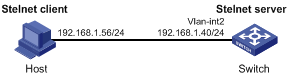
Configuration procedure
1. Configure the Stelnet server:
# Generate RSA key pairs.
<Switch> system-view
[Switch] public-key local create rsa
The range of public key size is (512 ~ 2048).
If the key modulus is greater than 512, it will take a few minutes.
Press CTRL+C to abort.
Input the modulus length [default = 1024]:
Generating Keys...
........................++++++
...................++++++
..++++++++
............++++++++
Create the key pair successfully.
# Generate a DSA key pair.
[Switch] public-key local create dsa
The range of public key size is (512 ~ 2048).
If the key modulus is greater than 512, it will take a few minutes.
Press CTRL+C to abort.
Input the modulus length [default = 1024]:
Generating Keys...
.++++++++++++++++++++++++++++++++++++++++++++++++++*
........+......+.....+......................................+
...+.................+..........+...+.
Create the key pair successfully.
# Enable the Stelnet server.
[Switch] ssh server enable
# Assign an IP address to VLAN-interface 2. The Stelnet client uses this address as the destination for SSH connection.
[Switch] interface vlan-interface 2
[Switch-Vlan-interface2] ip address 192.168.1.40 255.255.255.0
[Switch-Vlan-interface2] quit
# Set the authentication mode to AAA for the user lines.
[Switch] line vty 0 63
[Switch-line-vty0-63] authentication-mode scheme
[Switch-line-vty0-63] quit
# Create a local device management user client001.
[Switch] local-user client001 class manage
# Set the password to aabbcc in plain text for the local user client001.
[Switch-luser-manage-client001] password simple aabbcc
# Authorize the local user client001 to use the SSH service.
[Switch-luser-manage-client001] service-type ssh
# Assign the user role network-admin to the local user client001.
[Switch-luser-manage-client001] authorization-attribute user-role network-admin
[Switch-luser-manage-client001] quit
# Create an SSH user client001, and specify the service type as stelnet and the authentication method as password for the user.
[Switch] ssh user client001 service-type stelnet authentication-type password
2. Establish a connection to the Stelnet server:
There are different types of Stelnet client software, such as PuTTY and OpenSSH. This example uses an Stelnet client that runs PuTTY version 0.58.
To establish a connection to the Stelnet server:
a. Launch PuTTY.exe to enter the interface shown in Figure 34.
b. In the Host Name (or IP address) field, enter the IP address 192.168.1.40 of the Stelnet server.
Figure 34 Specifying the host name (or IP address)
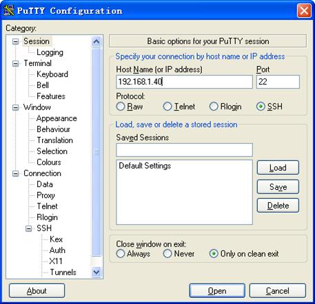
c. Click Open to connect to the server.
If the connection is successfully established, the system asks you to enter the username and password. After entering the username (client001 in this example) and password (aabbcc in this example), you can enter the CLI of the server.
Publickey authentication enabled Stelnet server configuration example
Network requirements
As shown in Figure 35, the switch acts as the Stelnet server, and it uses publickey authentication and the RSA public key algorithm.
Establish an Stelnet connection between the host and the switch, so you can log in to the switch for configuration management.
Configuration procedure
In the server configuration, the client's host public key is required. Use the client software to generate RSA key pairs on the client before configuring the Stelnet server.
There are different types of Stelnet client software, such as PuTTY and OpenSSH. This example uses an Stelnet client that runs PuTTY version 0.58.
The configuration procedure is as follows:
1. Generate RSA key pairs on the Stelnet client:
a. Run PuTTYGen.exe on the client, select SSH-2 RSA and click Generate.
Figure 36 Generating a key pair on the client
b. Continuously move the mouse and do not place the mouse over the green progress bar shown in Figure 37. Otherwise, the progress bar stops moving and the key pair generating progress stops.
c. After the key pair is generated, click Save public key, enter a file name (key.pub in this example), and click Save.
Figure 38 Saving a key pair on the client
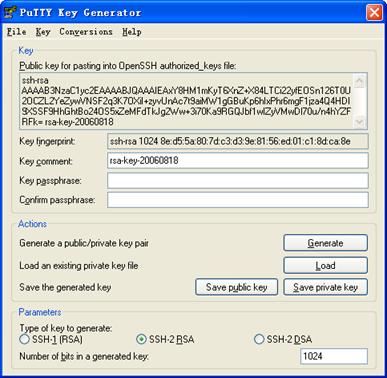
d. Click Save private key to save the private key.
A confirmation dialog box appears.
e. Click Yes, enter a file name (private.ppk in this example), and click Save.
f. Transmit the public key file to the server through FTP or TFTP. (Details not shown.)
2. Configure the Stelnet server:
# Generate RSA key pairs.
<Switch> system-view
[Switch] public-key local create rsa
The range of public key size is (512 ~ 2048).
If the key modulus is greater than 512, it will take a few minutes.
Press CTRL+C to abort.
Input the modulus length [default = 1024]:
Generating Keys...
........................++++++
...................++++++
..++++++++
............++++++++
Create the key pair successfully.
# Generate a DSA key pair.
[Switch] public-key local create dsa
The range of public key size is (512 ~ 2048).
If the key modulus is greater than 512, it will take a few minutes.
Press CTRL+C to abort.
Input the modulus length [default = 1024]:
Generating Keys...
.++++++++++++++++++++++++++++++++++++++++++++++++++*
........+......+.....+......................................+
...+.................+..........+...+
Create the key pair successfully.
# Enable the Stelnet server.
[Switch] ssh server enable
# Assign an IP address to VLAN-interface 2. The Stelnet client uses this address as the destination for SSH connection.
[Switch] interface vlan-interface 2
[Switch-Vlan-interface2] ip address 192.168.1.40 255.255.255.0
[Switch-Vlan-interface2] quit
# Set the authentication mode to AAA for the user lines.
[Switch] line vty 0 63
[Switch-line-vty0-63] authentication-mode scheme
[Switch-line-vty0-63] quit
# Import the client's public key from file key.pub and name it switchkey.
[Switch] public-key peer switchkey import sshkey key.pub
# Create an SSH user client002, specify the authentication method as publickey for the user, and assign the public key switchkey to the user.
[Switch] ssh user client002 service-type stelnet authentication-type publickey assign publickey switchkey
# Create a local device management user client002.
[Switch] local-user client002 class manage
# Authorize the local user client002 to use the SSH service.
[Switch-luser-manage-client002] service-type ssh
# Assign the user role network-admin to the local user client002.
[Switch-luser-manage-client002] authorization-attribute user-role network-admin
[Switch-luser-manage-client002] quit
3. Specify the private key file and establish a connection to the Stelnet server:
a. Launch PuTTY.exe on the Stelnet client to enter the interface shown in Figure 39.
b. In the Host Name (or IP address) field, enter the IP address 192.168.1.40 of the Stelnet server.
Figure 39 Specifying the host name (or IP address)
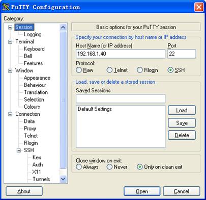
c. Select Connection > SSH from the navigation tree.
The window shown in Figure 40 appears.
d. Specify the Preferred SSH protocol version as 2.
Figure 40 Specifying the preferred SSH version
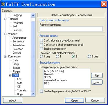
e. Select Connection > SSH > Auth from the navigation tree.
The window shown in Figure 41 appears.
f. Click Browse… to bring up the file selection window, navigate to the private key file (private.ppk in this example), and click OK.
Figure 41 Specifying the private key file
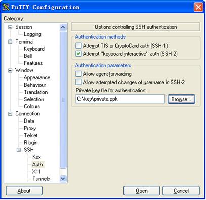
g. Click Open to connect to the server.
If the connection is successfully established, the system asks you to enter the username. After entering the username (client002), you can enter the CLI of the server.
Password authentication enabled Stelnet client configuration example
Network requirements
As shown in Figure 42:
· Switch B acts as the Stelnet server and uses password authentication.
· The username and password of the client are saved on Switch B.
Establish an Stelnet connection between Switch A and Switch B, so you can log in to Switch B for configuration management.
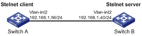
Configuration procedure
1. Configure the Stelnet server:
# Generate RSA key pairs.
<SwitchB> system-view
[SwitchB] public-key local create rsa
The range of public key size is (512 ~ 2048).
If the key modulus is greater than 512, it will take a few minutes.
Press CTRL+C to abort.
Input the modulus length [default = 1024]:
Generating Keys...
........................++++++
...................++++++
..++++++++
............++++++++
Create the key pair successfully.
# Generate a DSA key pair.
[SwitchB] public-key local create dsa
The range of public key size is (512 ~ 2048).
If the key modulus is greater than 512, it will take a few minutes.
Press CTRL+C to abort.
Input the modulus length [default = 1024]:
Generating Keys...
.++++++++++++++++++++++++++++++++++++++++++++++++++*
........+......+.....+......................................+
...+.................+..........+...+
Create the key pair successfully.
# Enable the Stelnet server.
[SwitchB] ssh server enable
# Assign an IP address to VLAN-interface 2. The Stelnet client uses this address as the destination address of the SSH connection.
[SwitchB] interface vlan-interface 2
[SwitchB-Vlan-interface2] ip address 192.168.1.40 255.255.255.0
[SwitchB-Vlan-interface2] quit
# Set the authentication mode to AAA for the user lines.
[SwitchB] line vty 0 63
[SwitchB-line-vty0-63] authentication-mode scheme
[SwitchB-line-vty0-63] quit
# Create a local device management user client001.
[SwitchB] local-user client001 class manage
# Set the password to aabbcc in plain text for the local user client001.
[SwitchB-luser-manage-client001] password simple aabbcc
# Authorize the local user client001 to use the SSH service.
[SwitchB-luser-manage-client001] service-type ssh
# Assign the user role network-admin to the local user client001.
[SwitchB-luser-manage-client001] authorization-attribute user-role network-admin
[SwitchB-luser-manage-client001] quit
# Create an SSH user client001, and specify the service type as stelnet and the authentication method as password for the user.
[SwitchB] ssh user client001 service-type stelnet authentication-type password
2. Establish a connection to the Stelnet server 192.168.1.40:
# Assign an IP address to VLAN-interface 2.
<SwitchA> system-view
[SwitchA] interface vlan-interface 2
[SwitchA-Vlan-interface2] ip address 192.168.1.56 255.255.255.0
[SwitchA-Vlan-interface2] quit
[SwitchA] quit
Before establishing a connection to the server, you can configure the server's host public key on the client to authenticate the server.
? To configure the server's host public key of the server on the client, perform the following tasks:
# Use the display public-key local dsa public command on the server to display the server's host public key.
# Enter public key view of the client and copy the host public key of the server to the client.
[SwitchA] public-key peer key1
Enter public key view. Return to system view with "peer-public-key end" command.
[SwitchA-pkey-public-key-key1]308201B73082012C06072A8648CE3804013082011F0281810
0D757262C4584C44C211F18BD96E5F0
[SwitchA-pkey-public-key-key1]61C4F0A423F7FE6B6B85B34CEF72CE14A0D3A5222FE08CECE
65BE6C265854889DC1EDBD13EC8B274
[SwitchA-pkey-public-key-key1]DA9F75BA26CCB987723602787E922BA84421F22C3C89CB9B0
6FD60FE01941DDD77FE6B12893DA76E
[SwitchA-pkey-public-key-key1]EBC1D128D97F0678D7722B5341C8506F358214B16A2FAC4B3
68950387811C7DA33021500C773218C
[SwitchA-pkey-public-key-key1]737EC8EE993B4F2DED30F48EDACE915F0281810082269009E
14EC474BAF2932E69D3B1F18517AD95
[SwitchA-pkey-public-key-key1]94184CCDFCEAE96EC4D5EF93133E84B47093C52B20CD35D02
492B3959EC6499625BC4FA5082E22C5
[SwitchA-pkey-public-key-key1]B374E16DD00132CE71B020217091AC717B612391C76C1FB2E
88317C1BD8171D41ECB83E210C03CC9
[SwitchA-pkey-public-key-key1]B32E810561C21621C73D6DAAC028F4B1585DA7F42519718CC
9B09EEF0381840002818000AF995917
[SwitchA-pkey-public-key-key1]E1E570A3F6B1C2411948B3B4FFA256699B3BF871221CC9C5D
F257523777D033BEE77FC378145F2AD
[SwitchA-pkey-public-key-key1]D716D7DB9FCABB4ADBF6FB4FDB0CA25C761B308EF53009F71
01F7C62621216D5A572C379A32AC290
[SwitchA-pkey-public-key-key1]E55B394A217DA38B65B77F0185C8DB8095522D1EF044B465E
8716261214A5A3B493E866991113B2D
[SwitchA-pkey-public-key-key1]485348
[SwitchA-pkey-public-key-key1] peer-public-key end
[SwitchA] quit
# Establish an SSH connection to the server 192.168.1.40 and specify the host public key of the server.
<SwitchA> ssh2 192.168.1.40 publickey key1
Username: client001
[email protected]'s password:
<SwitchA> ssh2 192.168.1.40 publickey key1
Username: client001
Press CTRL+C to abort.
Connecting to 192.168.1.40 port 22.
[email protected]'s password:
Enter a character ~ and a dot to abort.
******************************************************************************
* Copyright (c) 2004-2015 Hangzhou H3C Tech. Co., Ltd. All rights reserved. *
* Without the owner's prior written consent, *
* no decompiling or reverse-engineering shall be allowed. *
******************************************************************************
<SwitchB>
After you enter the correct password, you successfully log in to Switch B.
? If you do not configure the server's host public key on the client, when you access the server, the system will ask you whether to continue with the access. Select Yes to access the server and download the server's host public key.
<SwitchA> ssh2 192.168.1.40
Username: client001
The server is not authenticated. Continue? [Y/N]:y
Do you want to save the server public key? [Y/N]:y
[email protected]'s password:
<SwitchA> ssh2 192.168.1.40
Username: client001
Press CTRL+C to abort.
Connecting to 192.168.1.40 port 22.
The server is not authenticated. Continue? [Y/N]:y
Do you want to save the server public key? [Y/N]:y
[email protected]'s password:
Enter a character ~ and a dot to abort.
******************************************************************************
* Copyright (c) 2004-2015 Hangzhou H3C Tech. Co., Ltd. All rights reserved. *
* Without the owner's prior written consent, *
* no decompiling or reverse-engineering shall be allowed. *
******************************************************************************
<SwitchB>
After you enter the correct password, you can successfully log in to Switch B. At the next connection attempt, the system will not ask you to authenticate the server because the server's host public key has been saved on the client.
Publickey authentication enabled Stelnet client configuration example
Network requirements
As shown in Figure 43, Switch B acts as the Stelnet server, and it uses publickey authentication and the DSA public key algorithm.
Establish an Stelnet connection between Switch A and Switch B, so you can log in to Switch B for configuration management.
Configuration procedure
In the server configuration, the client public key is required. Use the client software to generate a DSA key pair on the client before configuring the Stelnet server.
1. Configure the Stelnet client:
# Assign an IP address to VLAN-interface 2.
<SwitchA> system-view
[SwitchA] interface vlan-interface 2
[SwitchA-Vlan-interface2] ip address 192.168.1.56 255.255.255.0
[SwitchA-Vlan-interface2] quit
# Generate a DSA key pair.
[SwitchA] public-key local create dsa
The range of public key size is (512 ~ 2048).
If the key modulus is greater than 512, it will take a few minutes.
Press CTRL+C to abort.
Input the modulus length [default = 1024]:
Generating Keys...
.++++++++++++++++++++++++++++++++++++++++++++++++++*
........+......+.....+......................................+
...+.................+..........+...+
Create the key pair successfully.
# Export the DSA host public key to file key.pub.
[SwitchA] public-key local export dsa ssh2 key.pub
[SwitchA] quit
# Transmit the public key file key.pub to the server through FTP or TFTP. (Details not shown.)
2. Configure the Stelnet server:
# Generate RSA key pairs.
<SwitchB> system-view
[SwitchB] public-key local create rsa
The range of public key size is (512 ~ 2048)
If the key modulus is greater than 512, it will take a few minutes.
Press CTRL+C to abort.
Input the modulus length [default = 1024]:
Generating Keys...
........................++++++
...................++++++
..++++++++
............++++++++
Create the key pair successfully.
# Generate a DSA key pair.
[SwitchB] public-key local create dsa
The range of public key size is (512 ~ 2048).
If the key modulus is greater than 512, it will take a few minutes.
Press CTRL+C to abort.
Input the modulus length [default = 1024]:
Generating Keys...
.++++++++++++++++++++++++++++++++++++++++++++++++++*
........+......+.....+......................................+
...+.................+..........+...+
Create the key pair successfully.
# Enable the Stelnet server.
[SwitchB] ssh server enable
# Assign an IP address to VLAN-interface 2. The Stelnet client uses this address as the destination address of the SSH connection.
[SwitchB] interface vlan-interface 2
[SwitchB-Vlan-interface2] ip address 192.168.1.40 255.255.255.0
[SwitchB-Vlan-interface2] quit
# Set the authentication mode to AAA for the user lines.
[SwitchB] line vty 0 63
[SwitchB-line-vty0-63] authentication-mode scheme
[SwitchB-line-vty0-63] quit
# Import the peer public key from the file key.pub, and name it switchkey.
[SwitchB] public-key peer switchkey import sshkey key.pub
# Create an SSH user client002, specify the authentication method as publickey for the user, and assign the public key switchkey to the user.
[SwitchB] ssh user client002 service-type stelnet authentication-type publickey assign publickey switchkey
# Create a local device management user client002.
[SwitchB] local-user client002 class manage
# Authorize the local user client002 to use the SSH service.
[SwitchB-luser-manage-client002] service-type ssh
# Assign the user role network-admin to the local user client002.
[SwitchB-luser-manage-client002] authorization-attribute user-role network-admin
[SwitchB-luser-manage-client002] quit
3. Establish an SSH connection to the Stelnet server 192.168.1.40.
<SwitchA> ssh2 192.168.1.40
Username: client002
The server is not authenticated. Continue? [Y/N]:y
Do you want to save the server public key? [Y/N]:n
<SwitchA> ssh2 192.168.1.40
Username: client002
Press CTRL+C to abort.
Connecting to 192.168.1.40 port 22.
The server is not authenticated. Continue? [Y/N]:y
Do you want to save the server public key? [Y/N]:n
[email protected]'s password:
Enter a character ~ and a dot to abort.
******************************************************************************
* Copyright (c) 2004-2015 Hangzhou H3C Tech. Co., Ltd. All rights reserved. *
* Without the owner's prior written consent, *
* no decompiling or reverse-engineering shall be allowed. *
******************************************************************************
<SwitchB>
You can log in to Switch B successfully for the first time without configuring its host public key, because the client supports the first authentication by default.
SFTP configuration examples
Unless otherwise noted, devices in the configuration examples operate in non-FIPS mode.
When you configure SFTP on devices operating in FIPS mode, follow these guidelines:
· The modulus length of the key pair must be 2048 bits.
· When the device acts as the SFTP server, only RSA key pairs are supported. Do not generate a DSA key pair on the SFTP server.
Password authentication enabled SFTP server configuration example
Network requirements
As shown in Figure 44:
· The switch acts as the SFTP server and uses password authentication.
· The username and password of the client are saved on the switch.
Establish an SFTP connection between the host and the switch, so you can log in to the switch to execute file management and transfer operations.
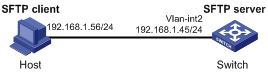
Configuration procedure
1. Configure the SFTP server:
# Generate RSA key pairs.
<Switch> system-view
[Switch] public-key local create rsa
The range of public key size is (512 ~ 2048).
If the key modulus is greater than 512, it will take a few minutes.
Press CTRL+C to abort.
Input the modulus length [default = 1024]:
Generating Keys...
........................++++++
...................++++++
..++++++++
............++++++++
Create the key pair successfully.
# Generate a DSA key pair.
[Switch] public-key local create dsa
The range of public key size is (512 ~ 2048).
If the key modulus is greater than 512, it will take a few minutes.
Press CTRL+C to abort.
Input the modulus length [default = 1024]:
Generating Keys...
.++++++++++++++++++++++++++++++++++++++++++++++++++*
........+......+.....+......................................+
...+.................+..........+...+
Create the key pair successfully.
# Enable the SFTP server.
[Switch] sftp server enable
# Assign an IP address to VLAN-interface 2. The SFTP client uses this address as the destination for SSH connection.
[Switch] interface vlan-interface 2
[Switch-Vlan-interface2] ip address 192.168.1.45 255.255.255.0
[Switch-Vlan-interface2] quit
# Create a local device management user client002.
[Switch] local-user client002 class manage
# Set the password to aabbcc in plain text for the local user client002.
[Switch-luser-manage-client002] password simple aabbcc
# Authorize the local user client002 to use the SSH service.
[Switch-luser-manage-client002] service-type ssh
# Assign the user role network-admin and working directory flash:/ to the local user client002.
[Switch-luser-manage-client002] authorization-attribute user-role network-admin work-directory flash:/
[Switch-luser-manage-client002] quit
# Create an SSH user client002, specify the authentication method as password and service type as sftp for the user.
[Switch] ssh user client002 service-type sftp authentication-type password
2. Establish a connection between the SFTP client and the SFTP server:
The device supports different types of SFTP client software. This example uses an SFTP client that runs PSFTP of PuTTy version 0.58.
|
|
NOTE: PSFTP supports only password authentication. |
To establish a connection to the SFTP server:
a. Run the psftp.exe to launch the client interface shown in Figure 45, and enter the following command:
open 192.168.1.45
b. Enter username client002 and password aabbcc as prompted to log in to the SFTP server.
Figure 45 SFTP client interface
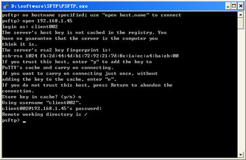
Publickey authentication enabled SFTP client configuration example
Network requirements
As shown in Figure 46, Switch B acts as the SFTP server, and it uses publickey authentication and the RSA public key algorithm.
Establish an SFTP connection between Switch A and Switch B, so you can log in to Switch B to execute file management and transfer operations.
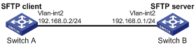
Configuration procedure
In the server configuration, the client's host public key is required. Use the client software to generate the RSA key pairs on the client before configuring the SFTP server.
1. Configure the SFTP client:
# Assign an IP address to VLAN-interface 2.
<SwitchA> system-view
[SwitchA] interface vlan-interface 2
[SwitchA-Vlan-interface2] ip address 192.168.0.2 255.255.255.0
[SwitchA-Vlan-interface2] quit
# Generate RSA key pairs.
[SwitchA] public-key local create rsa
The range of public key size is (512 ~ 2048).
If the key modulus is greater than 512, it will take a few minutes.
Press CTRL+C to abort.
Input the modulus length [default = 1024]:
Generating Keys...
........................++++++
...................++++++
..++++++++
............++++++++
Create the key pair successfully.
# Export the host public key to the file pubkey.
[SwitchA] public-key local export rsa ssh2 pubkey
[SwitchA] quit
# Transmit the public key file pubkey to the server through FTP or TFTP. (Details not shown.)
2. Configure the SFTP server:
# Generate RSA key pairs.
<SwitchB> system-view
[SwitchB] public-key local create rsa
The range of public key size is (512 ~ 2048).
If the key modulus is greater than 512, it will take a few minutes.
Press CTRL+C to abort.
Input the modulus length [default = 1024]:
Generating Keys...
........................++++++
...................++++++
..++++++++
............++++++++
Create the key pair successfully.
# Generate a DSA key pair.
[SwitchB] public-key local create dsa
The range of public key size is (512 ~ 2048).
If the key modulus is greater than 512, it will take a few minutes.
Press CTRL+C to abort.
Input the modulus length [default = 1024]:
Generating Keys...
.++++++++++++++++++++++++++++++++++++++++++++++++++*
........+......+.....+......................................+
...+.................+..........+...+
Create the key pair successfully.
# Enable the SFTP server.
[SwitchB] sftp server enable
# Assign an IP address to VLAN-interface 2. The SSH client uses this address as the destination for SSH connection.
[SwitchB] interface vlan-interface 2
[SwitchB-Vlan-interface2] ip address 192.168.0.1 255.255.255.0
[SwitchB-Vlan-interface2] quit
# Import the peer public key from the file pubkey, and name it switchkey.
[SwitchB] public-key peer switchkey import sshkey pubkey
# Create an SSH user client001, and specify the service type as sftp and the authentication method as publickey for the user. Assign the public key switchkey to the user.
[SwitchB] ssh user client001 service-type sftp authentication-type publickey assign publickey switchkey
# Create a local device management user client001.
[SwitchB] local-user client001 class manage
# Authorize the local user client001 to use the SSH service.
[SwitchB-luser-manage-client001] service-type ssh
# Assign the user role network-admin and working directory flash:/ to the local user client001.
[SwitchB-luser-manage-client001] authorization-attribute user-role network-admin work-directory flash:/
[SwitchB-luser-manage-client001] quit
3. Establish a connection to the SFTP server:
# Establish a connection to the SFTP server and enter SFTP client view.
<SwitchA> sftp 192.168.0.1 identity-key rsa
Username: client001
Press CTRL+C to abort.
Connecting to 192.168.0.1 port 22.
The server is not authenticated. Continue? [Y/N]:y
Do you want to save the server public key? [Y/N]:n
sftp>
# Display files under the current directory of the server, delete the file z, and verify the result.
sftp> dir -l
-rwxrwxrwx 1 noone nogroup 1759 Aug 23 06:52 config.cfg
-rwxrwxrwx 1 noone nogroup 225 Aug 24 08:01 pubkey2
-rwxrwxrwx 1 noone nogroup 283 Aug 24 07:39 pubkey
drwxrwxrwx 1 noone nogroup 0 Sep 01 06:22 new
-rwxrwxrwx 1 noone nogroup 225 Sep 01 06:55 pub
-rwxrwxrwx 1 noone nogroup 0 Sep 01 08:00 z
sftp> delete z
Removing /z
sftp> dir -l
-rwxrwxrwx 1 noone nogroup 1759 Aug 23 06:52 config.cfg
-rwxrwxrwx 1 noone nogroup 225 Aug 24 08:01 pubkey2
-rwxrwxrwx 1 noone nogroup 283 Aug 24 07:39 pubkey
drwxrwxrwx 1 noone nogroup 0 Sep 01 06:22 new
-rwxrwxrwx 1 noone nogroup 225 Sep 01 06:55 pub
# Add a directory new1 and verify the result.
sftp> mkdir new1
sftp> dir -l
-rwxrwxrwx 1 noone nogroup 1759 Aug 23 06:52 config.cfg
-rwxrwxrwx 1 noone nogroup 225 Aug 24 08:01 pubkey2
-rwxrwxrwx 1 noone nogroup 283 Aug 24 07:39 pubkey
drwxrwxrwx 1 noone nogroup 0 Sep 01 06:22 new
-rwxrwxrwx 1 noone nogroup 225 Sep 01 06:55 pub
drwxrwxrwx 1 noone nogroup 0 Sep 02 06:30 new1
# Rename directory new1 to new2 and verify the result.
sftp> rename new1 new2
sftp> dir -l
-rwxrwxrwx 1 noone nogroup 1759 Aug 23 06:52 config.cfg
-rwxrwxrwx 1 noone nogroup 225 Aug 24 08:01 pubkey2
-rwxrwxrwx 1 noone nogroup 283 Aug 24 07:39 pubkey
drwxrwxrwx 1 noone nogroup 0 Sep 01 06:22 new
-rwxrwxrwx 1 noone nogroup 225 Sep 01 06:55 pub
drwxrwxrwx 1 noone nogroup 0 Sep 02 06:33 new2
# Download the file pubkey2 from the server and save it as a local file public.
sftp> get pubkey2 public
Fetching / pubkey2 to public
/pubkey2 100% 225 1.4KB/s 00:00
# Upload the local file pu to the server, save it as puk, and verify the result.
sftp> put pu puk
Uploading pu to / puk
sftp> dir -l
-rwxrwxrwx 1 noone nogroup 1759 Aug 23 06:52 config.cfg
-rwxrwxrwx 1 noone nogroup 225 Aug 24 08:01 pubkey2
-rwxrwxrwx 1 noone nogroup 283 Aug 24 07:39 pubkey
drwxrwxrwx 1 noone nogroup 0 Sep 01 06:22 new
drwxrwxrwx 1 noone nogroup 0 Sep 02 06:33 new2
-rwxrwxrwx 1 noone nogroup 283 Sep 02 06:35 pub
-rwxrwxrwx 1 noone nogroup 283 Sep 02 06:36 puk
sftp>
# Exit SFTP client view.
sftp> quit
<SwitchA>
SCP file transfer with password authentication
Unless otherwise noted, devices in the configuration examples operate in non-FIPS mode.
When you configure SCP on devices operating in FIPS mode, follow these guidelines:
· The modulus length of the key pair must be 2048 bits.
· When the device acts as the SCP server, only RSA key pairs are supported. Do not generate a DSA key pair on the SCP server.
Network requirements
As shown in Figure 47:
· Switch B acts as the SCP server and uses password authentication.
· The client's username and password are saved on Switch B.
Establish an SCP connection between Switch A and Switch B, so you can log in to Switch B to execute file transfer operations.
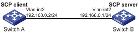
Configuration procedure
1. Configure the SCP server:
# Generate RSA key pairs.
<SwitchB> system-view
[SwitchB] public-key local create rsa
The range of public key size is (512 ~ 2048).
If the key modulus is greater than 512, it will take a few minutes.
Press CTRL+C to abort.
Input the modulus length [default = 1024]:
Generating Keys...
........................++++++
...................++++++
..++++++++
............++++++++
Create the key pair successfully.
# Generate a DSA key pair.
[SwitchB] public-key local create dsa
The range of public key size is (512 ~ 2048).
If the key modulus is greater than 512, it will take a few minutes.
Press CTRL+C to abort.
Input the modulus length [default = 1024]:
Generating Keys...
.++++++++++++++++++++++++++++++++++++++++++++++++++*
........+......+.....+......................................+
...+.................+..........+...+.
Create the key pair successfully.
# Enable the SCP server.
[SwitchB] scp server enable
# Configure an IP address for VLAN-interface 2. The client uses this address as the destination for SCP connection.
[SwitchB] interface vlan-interface 2
[SwitchB-Vlan-interface2] ip address 192.168.0.1 255.255.255.0
[SwitchB-Vlan-interface2] quit
# Create a local device management user client001.
[SwitchB] local-user client001 class manage
# Set the password to aabbcc in plain text for the local user client001.
[SwitchB-luser-manage-client001] password simple aabbcc
# Authorize the local user client001 to use the SSH service.
[SwitchB-luser-manage-client001] service-type ssh
[SwitchB-luser-manage-client001] quit
# Create an SSH user client001, and specify the service type as scp and the authentication method as password for the user.
[SwitchB] ssh user client001 service-type scp authentication-type password
2. Configure an IP address for VLAN-interface 2 on the SCP client.
<SwitchA> system-view
[SwitchA] interface vlan-interface 2
[SwitchA-Vlan-interface2] ip address 192.168.0.2 255.255.255.0
[SwitchA-Vlan-interface2] quit
[SwitchA] quit
3. Connect to the SCP server, download the file remote.bin from the server, and save it locally with the name local.bin.
<SwitchA> scp 192.168.0.1 get remote.bin local.bin
Username: client001
Press CTRL+C to abort.
Connecting to 192.168.0.1 port 22.
The server is not authenticated. Continue? [Y/N]:y
Do you want to save the server public key? [Y/N]:n
[email protected]’s password:
remote.bin 100% 2875 2.8KB/s 00:00
Configuring IP source guard
Overview
IP source guard (IPSG) prevents spoofing attacks by using an IPSG binding table to match legitimate packets. It drops all packets that do not match the table.
The IPSG binding table can include the following bindings:
· IP-interface.
· MAC-interface.
· IP-MAC-interface.
· IP-VLAN-interface.
· MAC-VLAN-interface.
· IP-MAC-VLAN-interface.
IPSG bindings include static bindings that are configured manually and dynamic bindings that are generated based on information from other modules.
|
|
NOTE: The IPSG feature is available on Layer 2 and Layer 3 Ethernet interfaces and VLAN interfaces. The term "interface" in this chapter collectively refers to these types of interfaces. You can use the port link-mode command to configure an Ethernet port as a Layer 2 or Layer 3 interface (see Layer 2—LAN Switching Configuration Guide). |
As shown in Figure 48, IPSG forwards only the packets that match one of the IPSG bindings.
Figure 48 Diagram for the IPSG feature
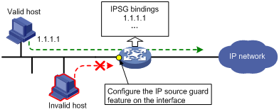
|
|
NOTE: IPSG is a per-interface packet filter. The feature configured on one interface does not affect packet forwarding on another interface. |
Static IPSG bindings
Static IPSG bindings are configured manually. They are suitable for scenarios where few hosts exist on a LAN and their IP addresses are manually configured. For example, you can configure a static IPSG binding on an interface that connects to a server. This binding allows the interface to receive packets only from the server.
Static IPv4SG bindings on an interface implement the following functions:
· Filter IPv4 incoming packets on the interface.
· Cooperate with ARP detection for user validity checking.
For information about ARP detection, see "Configuring ARP attack protection"
Dynamic IPSG bindings
IPSG can automatically obtain user information from other modules to generate dynamic bindings. The source modules include DHCP relay, DHCP snooping, and DHCP server.
DHCP-based IPSG bindings are suitable for scenarios where hosts on a LAN obtain IP addresses through DHCP. IPSG is configured on the DHCP snooping device or DHCP relay agent. It generates dynamic bindings based on the DHCP snooping entries or DHCP relay entries. IPSG allows only packets from the DHCP clients to pass through.
Dynamic bindings generated based on different source modules are for different usages:
|
Interface types |
Source modules |
Binding usage |
|
Layer 2 Ethernet port |
DHCP snooping |
Packet filtering. |
|
Layer 3 Ethernet interface/VLAN interface |
DHCP relay agent |
Packet filtering. |
|
DHCP server |
For cooperation with modules (such as the ARP detection module) to provide security services. |
For more information about DHCP snooping, DHCP relay, and DHCP server, see Layer 3—IP Services Configuration Guide.
IPSG configuration task list
|
(Required.) Enabling IPv4SG on an interface |
|
(Optional.) Configuring a static IPv4SG binding |
Configuring the IPv4SG feature
Enabling IPv4SG on an interface
When you enable IPSG on an interface, the static and dynamic IPSG are both enabled.
· Static IPv4SG uses static bindings configured by using the ip source binding command.
· Dynamic IPv4SG generates dynamic bindings from related source modules. IPv4SG uses the bindings to filter incoming IPv4 packets based on the matching criteria specified in the ip verify source command.
To implement dynamic IPv4SG, make sure the DHCP snooping or DHCP relay feature operates correctly on the network.
To enable the IPv4SG feature on an interface:
|
Step |
Command |
Remarks |
|
1. Enter system view. |
system-view |
N/A |
|
2. Enter interface view. |
interface interface-type interface-number |
The following interface types are supported: · Layer 2 Ethernet interface. · Layer 3 Ethernet interface. · VLAN interface. |
|
3. Enable the IPv4SG feature. |
ip verify source { ip-address | ip-address mac-address | mac-address } |
By default, the feature is disabled on an interface. If you configure this command on an interface multiple times, the most recent configuration takes effect. |
Configuring a static IPv4SG binding
You can configure global static and interface-specific static IPv4SG bindings.
Global static bindings take effect on all interfaces.
Interface-specific static bindings take priority over global static bindings. An interface first uses the static bindings on the interface to match packets. If no match is found, the interface uses the global bindings.
Configuring a global static IPv4SG binding
|
Step |
Command |
Remarks |
|
1. Enter system view. |
system-view |
N/A |
|
2. Configure a global static IPv4SG binding. |
ip source binding ip-address ip-address mac-address mac-address |
No global static IPv4SG binding exists. |
Configuring a static IPv4SG binding on an interface
|
Step |
Command |
Remarks |
|
1. Enter system view. |
system-view |
N/A |
|
2. Enter interface view. |
interface interface-type interface-number |
The following interface types are supported: · Layer 2 Ethernet interface. · Layer 3 Ethernet interface. · VLAN interface. |
|
3. Configure a static IPv4SG binding. |
ip source binding { ip-address ip-address | ip-address ip-address mac-address mac-address | mac-address mac-address } [ vlan vlan-id ] |
By default, no static IPv4SG binding is configured on an interface. The vlan vlan-id option is supported only in Layer 2 Ethernet interface view. To configure a static IPv4SG binding for the ARP detection function, the vlan vlan-id option must be specified, and ARP detection must be enabled for the specified VLAN. You can configure the same static IPv4SG binding on different interfaces. |
Displaying and maintaining IPSG
Execute display commands in any view and reset commands in user view.
|
Task |
Command |
|
Display IPv4SG bindings (in standalone mode). |
display ip source binding [ static | [ vpn-instance vpn-instance-name ] [ dhcp-relay | dhcp-server | dhcp-snooping ] ] [ ip-address ip-address ] [ mac-address mac-address ] [ vlan vlan-id ] [ interface interface-type interface-number ] [ slot slot-number ] |
|
Display IPv4SG bindings (in IRF mode). |
display ip source binding [ static | [ vpn-instance vpn-instance-name ] [ dhcp-relay | dhcp-server | dhcp-snooping ] ] [ ip-address ip-address ] [ mac-address mac-address ] [ vlan vlan-id ] [ interface interface-type interface-number ] [ chassis chassis-number slot slot-number ] |
IPSG configuration examples
Static IPv4SG configuration example
Network requirements
As shown in Figure 49, all hosts use static IP addresses.
Configure static IPv4SG bindings on Switch A and Switch B to meet the following requirements:
· FortyGigE 1/0/2 of Switch A allows only IP packets from Host C to pass.
· FortyGigE 1/0/1 of Switch A allows only IP packets from Host A to pass.
· All interfaces of Switch B allow IP packets from Host A to pass.
· FortyGigE 1/0/1 of Switch B allows IP packets from Host B to pass.
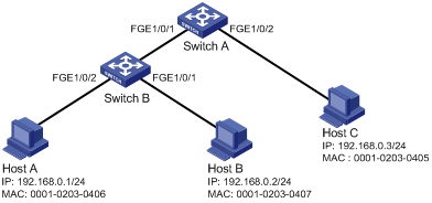
Configuration procedure
1. Configure Switch A:
# Configure IP addresses for the interfaces. (Details not shown.)
# Enable IPv4SG on FortyGigE 1/0/2.
<SwitchA> system-view
[SwitchA] interface fortygige 1/0/2
[SwitchA-FortyGigE1/0/2] ip verify source ip-address mac-address
# On FortyGigE 1/0/2, configure a static IPv4SG binding for Host C.
[SwitchA-FortyGigE1/0/2] ip source binding ip-address 192.168.0.3 mac-address 0001-0203-0405
[SwitchA-FortyGigE1/0/2] quit
# Enable IPv4SG on FortyGigE 1/0/1.
[SwitchA] interface fortygige 1/0/1
[SwitchA-FortyGigE1/0/1] ip verify source ip-address mac-address
# On FortyGigE 1/0/1, configure a static IPv4SG binding for Host A.
[SwitchA-FortyGigE1/0/1] ip source binding ip-address 192.168.0.1 mac-address 0001-0203-0406
[SwitchA-FortyGigE1/0/1] quit
2. Configure Switch B:
# Configure an IP address for each interface. (Details not shown.)
# Enable IPv4SG on FortyGigE 1/0/2.
<SwitchB> system-view
[SwitchB] interface fortygige 1/0/2
[SwitchB-FortyGigE1/0/2] ip verify source ip-address mac-address
[SwitchB-FortyGigE1/0/2] quit
# Configure a static IPv4SG binding for Host A.
[SwitchB] ip source binding ip-address 192.168.0.1 mac-address 0001-0203-0406
# Enable IPv4SG on FortyGigE 1/0/1.
[SwitchB] interface fortygige 1/0/1
[SwitchB-FortyGigE1/0/1] ip verify source ip-address mac-address
# On FortyGigE 1/0/1, configure a static IPv4SG binding for Host B.
[SwitchB-FortyGigE1/0/1] ip source binding mac-address 0001-0203-0407
[SwitchB-FortyGigE1/0/1] quit
Verifying the configuration
# Verify that the static IPv4SG bindings are configured successfully on Switch A.
<SwitchA> display ip source binding static
Total entries found: 2
IP Address MAC Address Interface VLAN Type
192.168.0.1 0001-0203-0405 FGE1/0/2 N/A Static
192.168.0.3 0001-0203-0406 FGE1/0/1 N/A Static
# Verify that the static IPv4SG bindings are configured successfully on Switch B.
<SwitchB> display ip source binding static
Total entries found: 2
IP Address MAC Address Interface VLAN Type
192.168.0.1 0001-0203-0406 N/A N/A Static
N/A 0001-0203-0407 FGE1/0/1 N/A Static
Dynamic IPv4SG using DHCP snooping configuration example
Network requirements
As shown in Figure 50, the host (the DHCP client) obtains an IP address from the DHCP server. Perform the following tasks:
· Enable DHCP snooping on the switch to make sure the DHCP client obtains an IP address from the authorized DHCP server. To generate a DHCP snooping entry for the DHCP client, enable recording of client information in DHCP snooping entries.
· Enable dynamic IPv4SG on FortyGigE 1/0/1 to filter incoming packets by using the IPv4SG bindings generated based on DHCP snooping entries. Only packets from the DHCP client are allowed to pass.
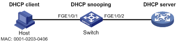
Configuration procedure
1. Configure the DHCP server:
For information about DHCP server configuration, see Layer 3—IP Services Configuration Guide.
2. Configure the device:
# Configure IP addresses for the interfaces. (Details not shown.)
# Enable DHCP snooping.
<Switch> system-view
[Switch] dhcp snooping enable
# Configure FortyGigE 1/0/2 as a trusted interface.
[Switch] interface fortygige 1/0/2
[Switch-FortyGigE1/0/2] dhcp snooping trust
[Switch-FortyGigE1/0/2] quit
# Enable IPv4SG on FortyGigE 1/0/1 and verify the source IP address and MAC address for dynamic IPSG.
[Switch] interface fortygige 1/0/1
[Switch-FortyGigE1/0/1] ip verify source ip-address mac-address
# Enable recording of client information in DHCP snooping entries on FortyGigE 1/0/1.
[Switch-FortyGigE1/0/1] dhcp snooping binding record
[Switch-FortyGigE1/0/1] quit
Verifying the configuration
# Verify that a dynamic IPv4SG binding is generated based on a DHCP snooping entry.
[Switch] display ip source binding dhcp-snooping
Total entries found: 1
IP Address MAC Address Interface VLAN Type
192.168.0.1 0001-0203-0406 FGE1/0/1 1 DHCP snooping
Dynamic IPv4SG using DHCP relay configuration example
Network requirements
As shown in Figure 51, DHCP relay is enabled on the switch. The host obtains an IP address from the DHCP server through the DHCP relay agent.
Enable dynamic IPv4SG on VLAN-interface 100 to filter received packets based on the DHCP relay entry generated on the switch.
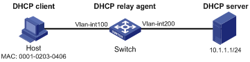
Configuration procedure
1. Configure dynamic IPv4SG:
# Configure IP addresses for the interfaces. (Details not shown.)
# Enable IPv4SG on VLAN-interface 100 and verify the source IP address and MAC address for dynamic IPSG.
<Switch> system-view
[Switch] interface vlan-interface 100
[Switch-Vlan-interface100] ip verify source ip-address mac-address
[Switch-Vlan-interface100] quit
2. Configure the DHCP relay agent:
# Enable the DHCP service.
[Switch] dhcp enable
# Enable recording DHCP relay client entries.
[Switch] dhcp relay client-information record
# Configure VLAN-interface 100 to work in DHCP relay mode.
[Switch] interface vlan-interface 100
[Switch-Vlan-interface100] dhcp select relay
# Specify the IP address of the DHCP server.
[Switch-Vlan-interface100] dhcp relay server-address 10.1.1.1
[Switch-Vlan-interface100] quit
Verifying the configuration
# Verify that a dynamic IPv4SG binding is generated based on a DHCP relay entry.
[Switch] display ip source binding dhcp-relay
Total entries found: 1
IP Address MAC Address Interface VLAN Type
192.168.0.1 0001-0203-0406 Vlan100 100 DHCP relay
Configuring ARP attack protection
Although ARP is easy to implement, it provides no security mechanism and is vulnerable to network attacks. An attacker can exploit ARP vulnerabilities to attack network devices in the following ways:
· Acts as a trusted user or gateway to send ARP packets so the receiving devices obtain incorrect ARP entries.
· Sends a large number of IP packets for which ARP cannot find corresponding MAC addresses (called unresolvable IP packets) to have the receiving device busy with resolving IP addresses until its CPU is overloaded.
· Sends a large number of ARP packets to overload the CPU of the receiving device.
For more information about ARP attack features and types, see ARP Attack Protection Technology White Paper.
ARP attack protection configuration task list
|
Tasks at a glance |
|
Flood prevention: · Configuring unresolvable IP attack protection (configured on gateways) ? Configuring ARP source suppression ? Configuring ARP blackhole routing · Configuring ARP packet rate limit (configured on access devices) · Configuring source MAC-based ARP attack detection (configured on gateways) |
|
User and gateway spoofing prevention: · Configuring ARP packet source MAC consistency check (configured on gateways) · Configuring ARP active acknowledgement (configured on gateways) · Configuring authorized ARP (configured on gateways) · Configuring ARP detection (configured on access devices) · Configuring ARP scanning and fixed ARP (configured on gateways) · Configuring ARP gateway protection (configured on access devices) · Configuring ARP filtering (configured on access devices) |
Configuring unresolvable IP attack protection
If a device receives a large number of unresolvable IP packets from a host, the following situations can occur.
· The device sends a large number of ARP requests, overloading the target subnets.
· The device keeps trying to resolve target IP addresses, overloading its CPU.
To protect the device from such unresolvable IP attacks, you can configure the following features:
· ARP source suppression—Stops resolving packets from an IP address if the number of unresolvable IP packets from the IP address exceeds the upper limit within 5 seconds. The device continues ARP resolution when the interval elapses. This feature is applicable if the attack packets have the same source addresses.
· ARP blackhole routing—Creates a blackhole route destined for an unresolved IP address. The device drops all matching packets until the blackhole route is deleted. A blackhole route is deleted when its aging timer (25 seconds) is reached or the route becomes reachable.
After a blackhole route is created for an unresolved IP address, the device immediately starts the first ARP blackhole route probe by sending an ARP request. If the resolution fails, the device continues probing according to the probe settings. If the IP address resolution succeeds in a probe, the device converts the blackhole route to a normal route. If an ARP blackhole route ages out before the device finishes all probes, the device deletes the blackhole route and will not perform the remaining probes.
This feature is applicable regardless of whether the attack packets have the same source addresses.
Configuring ARP source suppression
|
Command |
Remarks |
|
|
1. Enter system view. |
system-view |
N/A |
|
2. Enable ARP source suppression. |
arp source-suppression enable |
By default, ARP source suppression is disabled. |
|
3. Set the maximum number of unresolvable packets that the device can process per source IP address within 5 seconds. |
arp source-suppression limit limit-value |
By default, the maximum number is 10. |
Configuring ARP blackhole routing
|
Step |
Command |
Remarks |
|
1. Enter system view. |
system-view |
N/A |
|
2. Enable ARP blackhole routing. |
arp resolving-route enable |
By default, ARP blackhole routing is enabled. |
|
3. (Optional.) Set the interval at which the device probes ARP blackhole routes. |
arp resolving-route probe-interval interval |
The default setting is 1 second. |
|
4. (Optional.) Specify the number of ARP blackhole route probes for each unresolved IP address. |
arp resolving-route probe-count count |
The default setting is one probe. |
Displaying and maintaining unresolvable IP attack protection
Execute display commands in any view.
|
Task |
Command |
|
Display ARP source suppression configuration information. |
display arp source-suppression |
Configuration example
Network requirements
As shown in Figure 52, a LAN contains two areas: an R&D area in VLAN 10 and an office area in VLAN 20. Each area connects to the gateway (Device) through an access switch.
A large number of ARP requests are detected in the office area and are considered as the consequence of an unresolvable IP attack. To prevent such attacks, configure ARP source suppression or ARP blackhole routing.
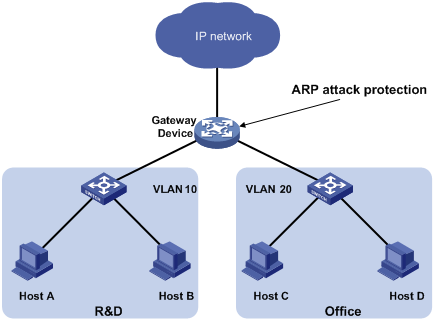
Configuration procedure
· If the attack packets have the same source address, configure ARP source suppression:
# Enable ARP source suppression.
<Device> system-view
[Device] arp source-suppression enable
# Configure the device to process a maximum of 100 unresolvable packets per source IP address within 5 seconds.
[Device] arp source-suppression limit 100
· If the attack packets have different source addresses, configure ARP blackhole routing:
# Enable ARP blackhole routing.
[Device] arp resolving-route enable
# Configure the device to probe ARP blackhole routes every 2 seconds.
[Device] arp resolving-route probe-interval 2
# Configure the device to perform five ARP blackhole route probes for each unresolved IP address.
[Device] arp resolving-route probe-count 5
Configuring ARP packet rate limit
|
|
IMPORTANT: This feature is available in Release 1138P01 and later versions. |
The ARP packet rate limit feature allows you to limit the rate of ARP packets delivered to the CPU. An ARP detection-enabled device will send all received ARP packets to the CPU for inspection. Processing excessive ARP packets will make the device malfunction or even crash. To solve this problem, configure ARP packet rate limit.
Configuration guidelines
Configure this feature when ARP detection, ARP snooping, or MFF is enabled, or when ARP flood attacks are detected.
Configuration procedure
This task sets a rate limit for ARP packets received on an interface. When the receiving rate of ARP packets on the interface exceeds the rate limit, those packets are discarded.
You can enable sending notifications to the SNMP module or enable logging for ARP packet rate limit.
· If notification sending is enabled, the device sends the highest threshold-crossed ARP packet rate within the sending interval in a notification to the SNMP module. You must use the snmp-agent target-host command to set the notification type and target host. For more information about notifications, see Network Management and Monitoring Command Reference.
· If logging for ARP packet rate limit is enabled, the device sends the highest threshold-crossed ARP packet rate within the sending interval in a log message to the information center. You can configure the information center module to set the log output rules. For more information about information center, see Network Management and Monitoring Configuration Guide.
To configure ARP packet rate limit:
|
Step |
Command |
Remarks |
|
1. Enter system view. |
system-view |
N/A |
|
2. (Optional.) Enable notification sending for ARP packet rate limit. |
snmp-agent trap enable arp [ rate-limit ] |
By default, notification sending for ARP packet rate limit is disabled. |
|
3. (Optional.) Enable logging for ARP packet rate limit. |
arp rate-limit log enable |
By default, logging for ARP packet rate limit is disabled. |
|
4. (Optional.) Set the notification and log message sending interval. |
arp rate-limit log interval seconds |
By default, the device sends notifications and log messages every 60 seconds. |
|
5. Enter Layer 2 Ethernet interface or Layer 2 aggregate interface view. |
N/A |
|
|
6. Enable ARP packet rate limit and set the rate limit. |
arp rate-limit [ pps ] |
By default, ARP packet rate limit is enabled. The default rate limit is 100 pps. |
|
|
NOTE: If you enable notification sending and logging for ARP packet rate limit on a Layer 2 aggregate interface, the features apply to all aggregation member ports. |
Configuring source MAC-based ARP attack detection
|
|
IMPORTANT: This feature is available in Release 1138P01 and later versions. |
This feature checks the number of ARP packets delivered to the CPU. If the number of packets from the same MAC address within 5 seconds exceeds a threshold, the device adds the MAC address to an ARP attack entry. Before the entry ages out, the device handles the attack by using either of the following methods:
· Monitor—Only generates log messages.
· Filter—Generates log messages and filters out subsequent ARP packets from that MAC address.
You can exclude the MAC addresses of some gateways and servers from this detection. This feature does not inspect ARP packets from those devices even if they are attackers.
Configuration procedure
To configure source MAC-based ARP attack detection:
|
Step |
Command |
Remarks |
|
1. Enter system view. |
system-view |
N/A |
|
2. Enable source MAC-based ARP attack detection and specify the handling method. |
arp source-mac { filter | monitor } |
By default, this feature is disabled. |
|
3. Set the threshold. |
The default threshold is 30. |
|
|
4. Set the aging timer for ARP attack entries. |
arp source-mac aging-time time |
By default, the lifetime is 300 seconds. |
|
5. (Optional.) Exclude specific MAC addresses from this detection. |
arp source-mac exclude-mac mac-address&<1-10> |
By default, no MAC addresses are excluded. |
|
|
NOTE: When an ARP attack entry ages out, ARP packets sourced from the MAC address in the entry can be processed correctly. |
Displaying and maintaining source MAC-based ARP attack detection
Execute display commands in any view.
|
Task |
Command |
|
Display ARP attack entries detected by source MAC-based ARP attack detection. |
display arp source-mac { slot slot-number | interface interface-type interface-number } |
Configuration example
Network requirements
As shown in Figure 53, the hosts access the Internet through a gateway (Device). If malicious users send a large number of ARP requests to the gateway, the gateway might crash and cannot process requests from the clients. To solve this problem, configure source MAC-based ARP attack detection on the gateway.
Figure 53 Network diagram
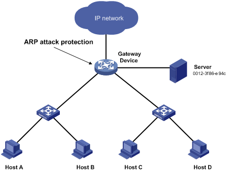
Configuration considerations
An attacker might forge a large number of ARP packets by using the MAC address of a valid host as the source MAC address. To prevent such attacks, configure the gateway in the following steps:
1. Enable source MAC-based ARP attack detection and specify the handling method as filter.
2. Set the threshold.
3. Set the lifetime for ARP attack entries.
4. Exclude the MAC address of the server from this detection.
Configuration procedure
# Enable source MAC-based ARP attack detection, and specify the handling method as filter.
<Device> system-view
[Device] arp source-mac filter
# Set the threshold to 30.
[Device] arp source-mac threshold 30
# Set the lifetime for ARP attack entries to 60 seconds.
[Device] arp source-mac aging-time 60
# Exclude MAC address 0012-3f86-e94c from this detection.
[Device] arp source-mac exclude-mac 0012-3f86-e94c
Configuring ARP packet source MAC consistency check
|
|
IMPORTANT: This feature is available in Release 1138P01 and later versions. |
This feature enables a gateway to filter out ARP packets whose source MAC address in the Ethernet header is different from the sender MAC address in the message body. This feature allows the gateway to learn correct ARP entries.
To enable ARP packet source MAC address consistency check:
|
Step |
Command |
Remarks |
|
1. Enter system view. |
system-view |
N/A |
|
2. Enable ARP packet source MAC address consistency check. |
arp valid-check enable |
By default, ARP packet source MAC address consistency check is disabled. |
Configuring ARP active acknowledgement
|
|
IMPORTANT: This feature is available in Release 1138P01 and later versions. |
Configure this feature on gateways to prevent user spoofing.
ARP active acknowledgement prevents a gateway from generating incorrect ARP entries.
In strict mode, a gateway performs more strict validity checks before creating an ARP entry:
· Upon receiving an ARP request destined for the gateway, the gateway sends an ARP reply but does not create an ARP entry.
· Upon receiving an ARP reply, the gateway determines whether it has resolved the sender IP address:
? If yes, the gateway performs active acknowledgement. When the ARP reply is verified as valid, the gateway creates an ARP entry.
? If no, the gateway discards the packet.
For ARP active acknowledgement to take effect in strict mode, make sure ARP blackhole routing is enabled.
To configure ARP active acknowledgement:
|
Step |
Command |
Remarks |
|
1. Enter system view. |
system-view |
N/A |
|
2. Enable the ARP active acknowledgement feature. |
arp active-ack [ strict ] enable |
By default, this feature is disabled. |
Configuring authorized ARP
|
|
IMPORTANT: This feature is available in Release 1138P01 and later versions. |
Authorized ARP entries are generated based on the DHCP clients' address leases on the DHCP server or dynamic client entries on the DHCP relay agent. For more information about DHCP server and DHCP relay agent, see Layer 3—IP Services Configuration Guide.
With authorized ARP enabled, an interface is disabled from learning dynamic ARP entries. This feature prevents user spoofing and allows only authorized clients to access network resources.
Configuration procedure
To enable authorized ARP:
|
Step |
Command |
Remarks |
|
1. Enter system view. |
system-view |
N/A |
|
2. Enter Layer 3 Ethernet interface, Layer 3 aggregate interface, or VLAN interface view. |
interface interface-type interface-number |
N/A |
|
3. Enable authorized ARP on the interface. |
arp authorized enable |
By default, authorized ARP is disabled. |
Configuring ARP detection
ARP detection enables access devices to block ARP packets from unauthorized clients to prevent user spoofing and gateway spoofing attacks. ARP detection does not check ARP packets received from ARP trusted ports.
ARP detection provides the following features:
· User validity check.
· ARP packet validity check.
· ARP restricted forwarding.
· ARP detection logging.
If both ARP packet validity check and user validity check are enabled, the former one applies first, and then the latter applies.
Configuring user validity check
Upon receiving an ARP packet from an ARP untrusted interface, the device compares the sender IP and MAC addresses against the static IP source guard binding entries and the DHCP snooping entries. If a match is found from those entries, the ARP packet is considered valid and is forwarded. If no match is found, the ARP packet is considered invalid and is discarded.
Static IP source guard binding entries are created by using the ip source binding command. For more information, see "Configuring IP source guard"
DHCP snooping entries are automatically generated by DHCP snooping. For more information, see Layer 3—IP Services Configuration Guide.
Configuration guidelines
When you configure user validity check, follow these guidelines:
· Make sure at least one among static IP source guard binding entries and DHCP snooping entries is available for user validity check. Otherwise, ARP packets received from ARP untrusted ports are discarded.
· You must specify a VLAN for an IP source guard binding entry. Otherwise, no ARP packets can match the IP source guard binding entry.
Configuration procedure
To configure user validity check:
|
Step |
Command |
Remarks |
|
1. Enter system view. |
system-view |
N/A |
|
2. Enter VLAN view. |
vlan vlan-id |
N/A |
|
3. Enable ARP detection. |
arp detection enable |
By default, ARP detection is disabled. |
|
4. Return to system view. |
quit |
N/A |
|
5. Enter Layer 2 Ethernet interface view. |
interface interface-type interface-number |
N/A |
|
6. (Optional.) Configure the interface as a trusted interface excluded from ARP detection. |
arp detection trust |
By default, an interface is untrusted. |
Configuring ARP packet validity check
Enable validity check for ARP packets received on untrusted ports and specify the following objects to be checked:
· src-mac—Checks whether the sender MAC address in the message body is identical to the source MAC address in the Ethernet header. If they are identical, the packet is forwarded. Otherwise, the packet is discarded.
· dst-mac—Checks the target MAC address of ARP replies. If the target MAC address is all-zero, all-one, or inconsistent with the destination MAC address in the Ethernet header, the packet is considered invalid and discarded.
· ip—Checks the sender and target IP addresses of ARP replies, and the sender IP address of ARP requests. All-one or multicast IP addresses are considered invalid and the corresponding packets are discarded.
To configure ARP packet validity check:
|
Step |
Command |
Remarks |
|
1. Enter system view. |
system-view |
N/A |
|
2. Enter VLAN view. |
vlan vlan-id |
N/A |
|
3. Enable ARP detection. |
arp detection enable |
By default, ARP detection is disabled. |
|
4. Return to system view. |
quit |
N/A |
|
5. Enable ARP packet validity check and specify the objects to be checked. |
arp detection validate { dst-mac | ip | src-mac } * |
By default, ARP packet validity check is disabled. |
|
6. Enter Layer 2 Ethernet interface view. |
interface interface-type interface-number |
N/A |
|
7. (Optional.) Configure the interface as a trusted interface excluded from ARP detection. |
arp detection trust |
By default, an interface is untrusted. |
Configuring ARP restricted forwarding
|
|
NOTE: ARP restricted forwarding does not apply to ARP packets with multiport MAC as their destination MAC addresses. |
ARP restricted forwarding controls the forwarding of ARP packets that are received on untrusted interfaces and have passed user validity check as follows:
· If the packets are ARP requests, they are forwarded through the trusted interface.
· If the packets are ARP replies, they are forwarded according to their destination MAC address. If no match is found in the MAC address table, they are forwarded through the trusted interface.
Configure user validity check before you configure ARP restricted forwarding.
To enable ARP restricted forwarding:
|
Step |
Command |
Remarks |
|
1. Enter system view. |
system-view |
N/A |
|
2. Enter VLAN view. |
vlan vlan-id |
N/A |
|
3. Enable ARP restricted forwarding. |
arp restricted-forwarding enable |
By default, ARP restricted forwarding is disabled. |
Enabling ARP detection logging
|
|
IMPORTANT: This feature is available in Release 1138P01 and later versions. |
The ARP detection logging feature enables a device to generate ARP detection log messages when illegal ARP packets are detected. An ARP detection log message contains the following information:
1. Receiving interface of the ARP packets.
2. Sender IP address.
3. Total number of dropped ARP packets.
The following is an example of an ARP detection log message:
Detected an inspection occurred on interface FortyGigE1/0/1 with IP address 172.18.48.55 (Total 10 packets dropped).
To enable ARP detection logging:
|
Step |
Command |
Remarks |
|
1. Enter system view. |
system-view |
N/A |
|
2. Enable ARP detection logging. |
arp detection log enable |
By default, ARP detection logging is disabled. |
Displaying and maintaining ARP detection
Execute display commands in any view and reset commands in user view.
|
Task |
Command |
|
Display the VLANs enabled with ARP detection. |
display arp detection |
|
Display the ARP detection statistics. |
display arp detection statistics [ interface interface-type interface-number ] |
|
Clear the ARP detection statistics. |
reset arp detection statistics [ interface interface-type interface-number ] |
User validity check and ARP packet validity check configuration example
Network requirements
As shown in Figure 54, configure Switch B to perform ARP packet validity check and user validity check based on static IP source guard binding entries and DHCP snooping entries for connected hosts.
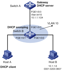
Configuration procedure
1. Add all interfaces on Switch B to VLAN 10, and specify the IP address of VLAN-interface 10 on Switch A. (Details not shown.)
2. Configure the DHCP server on Switch A, and configure DHCP address pool 0.
<SwitchA> system-view
[SwitchA] dhcp enable
[SwitchA] dhcp server ip-pool 0
[SwitchA-dhcp-pool-0] network 10.1.1.0 mask 255.255.255.0
3. Configure Host A (DHCP client) and Host B. (Details not shown.)
4. Configure Switch B:
# Enable DHCP snooping.
<SwitchB> system-view
[SwitchB] dhcp snooping enable
[SwitchB] interface fortygige 1/0/3
[SwitchB-FortyGigE1/0/3] dhcp snooping trust
[SwitchB-FortyGigE1/0/3] quit
[SwitchB] interface fortygige 1/0/1
[SwitchB-FortyGigE1/0/1] dhcp snooping binding record
[SwitchB-FortyGigE1/0/1] quit
# Enable ARP detection for VLAN 10.
[SwitchB] vlan 10
[SwitchB-vlan10] arp detection enable
# Configure the upstream interface as a trusted interface (an interface is an untrusted interface by default).
[SwitchB-vlan10] interface fortygige 1/0/3
[SwitchB-FortyGigE1/0/3] arp detection trust
[SwitchB-FortyGigE1/0/3] quit
# Configure a static IP source guard binding entry on interface FortyGigE 1/0/2 for user validity check.
[SwitchB] interface fortygige 1/0/2
[SwitchB-FortyGigE1/0/2] ip source binding ip-address 10.1.1.6 mac-address 0001-0203-0607 vlan 10
[SwitchB-FortyGigE1/0/2] quit
# Enable ARP packet validity check by checking the MAC addresses and IP addresses of ARP packets.
[SwitchB] arp detection validate dst-mac ip src-mac
After the configurations are completed, ARP packets received on interfaces FortyGigE 1/0/1 and FortyGigE 1/0/2 have their MAC and IP addresses checked first, and then are checked against the static IP source guard binding entries and finally DHCP snooping entries.
Configuring ARP scanning and fixed ARP
|
|
IMPORTANT: The features are available in Release 1138P01 and later versions. |
ARP scanning is typically used together with the fixed ARP feature in small-scale networks.
ARP scanning automatically creates ARP entries for devices in an address range. The device performs ARP scanning in the following steps:
1. Sends ARP requests for each IP address in the address range.
2. Obtains their MAC addresses through received ARP replies.
3. Creates dynamic ARP entries.
Fixed ARP converts existing dynamic ARP entries (including those generated through ARP scanning) to static ARP entries. This feature prevents ARP entries from being modified by attackers. Static ARP entries can also be manually configured by the arp static command.
Configuration restrictions and guidelines
When you configure ARP scanning and fixed ARP, follow these restrictions and guidelines:
· IP addresses in existing ARP entries are not scanned.
· ARP scanning will take some time. To stop an ongoing scan, press Ctrl + C. Dynamic ARP entries are created based on ARP replies received before the scan is terminated.
· The arp fixup command is a one-time operation. You can use this command again to convert the dynamic ARP entries learned later to static.
· Due to the limit on the total number of static ARP entries, some dynamic ARP entries might fail the conversion.
· The undo arp fixup command converts existing static ARP entries to dynamic ARP entries.
· To delete a static ARP entry converted from dynamic or a dynamic ARP entry converted from static, use the undo arp ip-address [ vpn-instance-name ] command. You can also use the reset arp all command to delete all ARP entries including the converted entries.
Configuration procedure
To configure ARP scanning and fixed ARP:
|
Step |
Command |
|
1. Enter system view. |
system-view |
|
2. Enter Layer 3 Ethernet interface, VLAN interface, or Layer 3 aggregate interface view. |
interface interface-type interface-number |
|
3. Trigger an ARP scanning. |
arp scan [ start-ip-address to end-ip-address ] |
|
4. Exit to system view. |
quit |
|
5. Enable fixed ARP. |
arp fixup |
Configuring ARP gateway protection
|
|
IMPORTANT: This feature is available in Release 1138P01 and later versions. |
Configure this feature on interfaces not connected with a gateway to prevent gateway spoofing attacks.
When such an interface receives an ARP packet, it checks whether the sender IP address in the packet is consistent with that of any protected gateway. If yes, it discards the packet. If not, it handles the packet correctly.
Configuration guidelines
When you configure ARP gateway protection, follow these guidelines:
· You can enable ARP gateway protection for a maximum of eight gateways on an interface.
· Do not configure both the arp filter source and arp filter binding commands on an interface.
· If ARP gateway protection works with ARP detection, MFF, and ARP snooping, ARP gateway protection applies first.
Configuration procedure
To configure ARP gateway protection:
|
Step |
Command |
Remarks |
|
|
1. Enter system view. |
system-view |
N/A |
|
|
2. Enter Layer 2 Ethernet interface or Layer 2 aggregate interface view. |
interface interface-type interface-number |
N/A |
|
|
3. Enable ARP gateway protection for the specified gateway. |
arp filter source ip-address |
By default, ARP gateway protection is disabled. |
|
Configuration example
Network requirements
As shown in Figure 55, Host B launches gateway spoofing attacks to Switch B. As a result, traffic that Switch B intends to send to Switch A is sent to Host B.
Configure Switch B to block such attacks.
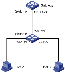
Configuration procedure
# Configure ARP gateway protection on Switch B.
<SwitchB> system-view
[SwitchB] interface fortygige 1/0/1
[SwitchB-FortyGigE1/0/1] arp filter source 10.1.1.1
[SwitchB-FortyGigE1/0/1] quit
[SwitchB] interface fortygige 1/0/2
[SwitchB-FortyGigE1/0/2] arp filter source 10.1.1.1
Verifying the configuration
# Verify that FortyGigE 1/0/1 and FortyGigE 1/0/2 discard the incoming ARP packets whose sender IP address is the IP address of the gateway.
Configuring ARP filtering
|
|
IMPORTANT: This feature is available in Release 1138P01 and later versions. |
The ARP filtering feature can prevent gateway spoofing and user spoofing attacks.
An interface enabled with this feature checks the sender IP and MAC addresses in a received ARP packet against permitted entries. If a match is found, the packet is handled correctly. If not, the packet is discarded.
Configuration guidelines
When you configure ARP filtering, follow these guidelines:
· You can configure a maximum of eight permitted entries on an interface.
· Do not configure both the arp filter source and arp filter binding commands on an interface.
· If ARP filtering works with ARP detection, MFF, and ARP snooping, ARP filtering applies first.
Configuration procedure
To configure ARP filtering:
|
Step |
Command |
Remarks |
|
1. Enter system view. |
system-view |
N/A |
|
2. Enter Layer 2 Ethernet interface or Layer 2 aggregate interface view. |
interface interface-type interface-number |
N/A |
|
3. Enable ARP filtering and configure a permitted entry. |
arp filter binding ip-address mac-address |
By default, ARP filtering is disabled. |
Configuration example
Network requirements
As shown in Figure 56, the IP and MAC addresses of Host A are 10.1.1.2 and 000f-e349-1233, respectively. The IP and MAC addresses of Host B are 10.1.1.3 and 000f-e349-1234, respectively.
Configure ARP filtering on FortyGigE 1/0/1 and FortyGigE 1/0/2 of Switch B to permit ARP packets from only Host A and Host B.
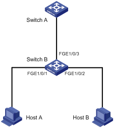
Configuration procedure
# Configure ARP filtering on Switch B.
<SwitchB> system-view
[SwitchB] interface fortygige 1/0/1
[SwitchB-FortyGigE1/0/1] arp filter binding 10.1.1.2 000f-e349-1233
[SwitchB-FortyGigE1/0/1] quit
[SwitchB] interface fortygige 1/0/2
[SwitchB-FortyGigE1/0/2] arp filter binding 10.1.1.3 000f-e349-1234
Verifying the configuration
# Verify that FortyGigE 1/0/1 permits ARP packets from Host A and discards other ARP packets.
# Verify that FortyGigE 1/0/2 permits ARP packets from Host B and discards other ARP packets.
Configuring uRPF
Overview
Unicast Reverse Path Forwarding (uRPF) protects a network against source address spoofing attacks, such as DoS and DDoS attacks.
Attackers send packets with a forged source address to access a system that uses IP-based authentication, in the name of authorized users or even the administrator. Even if the attackers or other hosts cannot receive any response packets, the attacks are still disruptive to the attacked target.
Figure 57 Source address spoofing attack
As shown in Figure 57, an attacker on Router A sends the server (Router B) requests with a forged source IP address 2.2.2.1 at a high rate, and Router B sends response packets to IP address 2.2.2.1 (Router C). Consequently, both Router B and Router C are attacked. If the administrator disconnects Router C by mistake, the network service is interrupted.
Attackers can also send packets with different forged source addresses or attack multiple servers simultaneously to block connections or even break down the network.
uRPF can prevent these source address spoofing attacks. It checks whether an interface that receives a packet is the output interface of the FIB entry that matches the source address of the packet. If not, uRPF considers it a spoofing attack and discards the packet.
uRPF check modes
uRPF supports strict and loose modes.
· Strict uRPF check—To pass strict uRPF check, the source address of a packet and the receiving interface must match the destination address and output interface of a FIB entry. In some scenarios (for example, asymmetrical routing), strict uRPF might discard valid packets. Strict uRPF is often deployed between a PE and a CE.
· Loose uRPF check—To pass loose uRPF check, the source address of a packet must match the destination address of a FIB entry. Loose uRPF can avoid discarding valid packets, but might let go attack packets. Loose uRPF is often deployed between ISPs, especially in asymmetrical routing.
uRPF operation
Figure 58 shows how uRPF works.
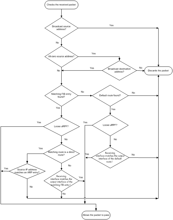
1. uRPF checks source address validity:
? Discards packets with a source broadcast address.
? Discards packets with an all-zero source address but a non-broadcast destination address. (A packet with source address 0.0.0.0 and destination address 255.255.255.255 might be a DHCP or BOOTP packet and cannot be discarded.)
? Proceeds to step 2 for other packets.
2. uRPF checks whether the source address matches a FIB entry:
? If yes, proceeds to step 3.
? If no, proceeds to step 6.
3. uRPF checks whether the check mode is loose:
? If yes, proceeds to step 8.
? If no, uRPF checks whether the matching route is a direct route:
- If yes, proceeds to step 5.
- If no, proceeds to step 4.
4. uRPF checks whether the receiving interface matches the output interface of the matching FIB entry:
? If yes, proceeds to step 8.
? If no, proceeds to step 9.
5. uRPF checks whether the source IP address matches an ARP entry:
? If yes, proceeds to step 8.
? If no, proceeds to step 9.
6. uRPF checks whether the FIB table has a default route:
? If yes, proceeds to step 7.
? If no, proceeds to step 9.
7. uRPF checks whether the check mode is loose:
? If yes, proceeds to step 8.
? If no, uRPF checks whether the output interface of the default route matches the receiving interface of the packet:
- If yes, proceeds to 8
- If no, proceeds to 9.
8. The packet passes the check and is forwarded.
9. The packet is discarded.
|
|
NOTE: uRPF does not check multicast packets. |
Network application
Figure 59 Network diagram
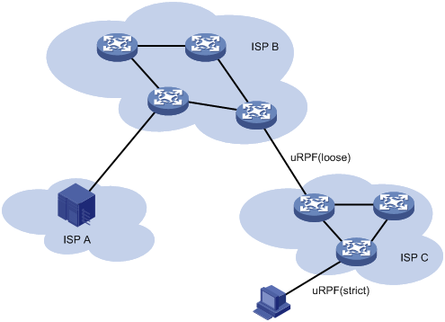
Configure strict uRPF check between an ISP network and a customer network, and loose uRPF check between ISPs.
Enabling uRPF
To enable uRPF globally:
|
Step |
Command |
Remarks |
|
1. Enter system view. |
system-view |
N/A |
|
2. Enable uRPF globally. |
ip urpf { loose | strict } |
By default, uRPF is disabled. |
Displaying and maintaining uRPF
Execute display commands in any view.
|
Task |
Command |
|
Display uRPF configuration (in standalone mode). |
display ip urpf [ slot slot-number ] |
|
Display uRPF configuration (in IRF mode). |
display ip urpf [ chassis chassis-number slot slot-number ] |
uRPF configuration example
Network requirements
As shown in Figure 60, a client (Switch A) directly connects to an ISP switch (Switch B). Enable strict uRPF check on Switch A and Switch B to prevent source address spoofing attacks.
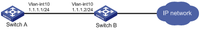
Configuration procedure
1. Enable strict uRPF check on Switch A.
<SwitchA> system-view
[SwitchA] ip urpf strict
2. Enable strict uRPF check on Switch B.
<SwitchB> system-view
[SwitchB] ip urpf strict
Configuring FIPS
Overview
Federal Information Processing Standards (FIPS) was developed by the National Institute of Standards and Technology (NIST) of the United States. FIPS specifies the requirements for cryptographic modules. FIPS 140-2 defines four levels of security, named "Level 1" to "Level 4", from low to high. The device supports Level 2.
Unless otherwise noted, in this document the term "FIPS" refers to FIPS 140-2.
Configuration restrictions and guidelines
When you configure FIPS, follow these restrictions and guidelines:
· After the fips mode enable command is executed, the system prompts you to choose a reboot method. If you do not make a choice within 30 seconds, the system uses the manual reboot method.
· Before you reboot the device to enter FIPS mode, the system automatically removes all key pairs configured in non-FIPS mode and all FIPS-incompliant digital certificates. FIPS-incompliant digital certificates are MD5-based certificates with the modulus length of key pairs less than 2048 bits. You cannot log in to the device through SSH after the device enters FIPS mode. To log in to the device in FIPS mode through SSH, first log in to the device through a console port, and then create a key pair for the SSH server.
· The password for entering the device in FIPS mode must comply with the password control policies, such as password length, complexity, and aging policy. When the aging timer for a password expires, the system prompts you to change the password. If you adjust the system time after the device enters FIPS mode, the login password might expire before the next login, because the original system time is typically much earlier than the actual time.
? If you choose the automatic reboot method, set the system time before executing the fips mode enable command.
? If you choose the manual reboot method, set the system time before configuring the local username and password.
· To use the manual reboot method, you must perform the following tasks:
a. Save the current configuration file.
b. Specify the current configuration file as the startup configuration file.
c. Delete the startup configuration file in binary format.
d. Reboot the device.
Otherwise, the commands that are not supported by FIPS mode, if they are in the configuration file, might be restored.
· The system enters an intermediate state between when the fips mode enable command is executed and when the system is rebooted. If you choose the manual reboot method, do not execute any commands except for the following commands:
? reboot.
? save.
? Other commands used for configuration preparation to enter FIPS mode.
· If a device enters FIPS or non-FIPS mode through automatic reboot, configuration rollback fails. To support configuration rollback, you must execute the save command after the device enters FIPS or non-FIPS mode.
· Do not use FIPS and non-FIPS devices to create an IRF fabric.
· To enable FIPS mode for an IRF fabric, you must reboot the entire IRF fabric.
· The default MDC supports FIPS commands. Other MDCs do not support FIPS commands.
Configuring FIPS mode
Entering FIPS mode
After you enable FIPS mode and reboot the device, the device operates in FIPS mode. The FIPS device has strict security requirements, and performs self-tests on cryptography modules to verify that they are operating correctly.
A FIPS device meets the requirements defined in Network Device Protection Profile (NDPP) of Common Criteria (CC).
The system provides two methods to enter FIPS mode: automatic reboot and manual reboot.
Automatic reboot
To use automatic reboot to enter FIPS mode:
1. Enable FIPS mode.
2. Select the automatic reboot method.
The system automatically performs the following tasks:
a. Create a default FIPS configuration file named fips-startup.cfg.
b. Specify the default file as the startup configuration file.
c. Prompt you to configure the username and password for next login.
You can press Ctrl+C to exit the configuring process. The fips mode enable command will not be executed.
3. Configure a username and password to log in to the device in FIPS mode.
The password must include at least 15 characters that contain uppercase and lowercase letters, digits, and special characters.
The system automatically uses the startup configuration file to reboot the device and enter FIPS mode. You can only use the configured username and password to log in to the FIPS device. After login, you are assigned the role of security administrator Crypto Officer.
Manual reboot
To use manual reboot to enter FIPS mode:
1. Enable the password control feature globally.
2. Set the number of character types a password must contain to 4, and set the minimum number of characters for each type to one character.
3. Set the minimum length of user passwords to 15 characters.
4. Add a local user account for device management, including the following items:
? A username.
? A password that complies with the password control policies as described in step 2 and step 3.
? A user role of network-admin or mdc-admin.
? A service type of terminal.
5. Delete the FIPS-incompliant local user service types Telnet and FTP.
6. Enable FIPS mode.
7. Select the manual reboot method.
8. Save the configuration file and specify it as the startup configuration file.
9. Delete the startup configuration file in binary format (an .mdb file).
10. Reboot the device.
The system enters FIPS mode. You can use the configured username and password to log in to the device in FIPS mode.
To enable FIPS mode:
|
Step |
Command |
Remarks |
|
1. Enter system view. |
system-view |
N/A |
|
2. Enable FIPS mode. |
fips mode enable |
By default, the FIPS mode is disabled. |
Configuration changes in FIPS mode
When the system enters FIPS mode, the following system changes occur:
· The user login authentication mode can only be scheme.
· The FTP/TFTP server and client are disabled.
· The Telnet server and client are disabled.
· SNMPv1 and SNMPv2c are disabled. Only SNMPv3 is available.
· The SSH server does not support SSHv1 clients and DSA key pairs.
· The generated RSA and DSA key pairs must have a modulus length of 2048 bits.
When the device acts as a server to authenticate a client through the public key, the key pair for the client must also have a modulus length of 2048 bits.
· SSH, SNMPv3, and IPsec do not support DES, 3DES, RC4, or MD5.
· The password control feature cannot be disabled globally. The undo password-control enable command does not take effect.
· The keys must contain at least 15 characters and 4 character types of uppercase and lowercase letters, digits, and special characters. This requirement applies to the following passwords:
? AAA server's shared key.
? IKE pre-shared key.
? SNMPv3 authentication key.
The password for a device management local user and password for switching user roles depend on password control policies. By default, the passwords must contain at least 15 characters and 4 character types of uppercase and lowercase letters, digits, and special characters.
Exiting FIPS mode
After you disable FIPS mode and reboot the device, the device operates in non-FIPS mode. The non-FIPS device does not have the security requirements of FIPS mode, and does not perform self-tests on cryptography modules.
The system provides two methods to exit FIPS mode: automatic reboot and manual reboot.
Automatic reboot
Select the automatic reboot method. The system automatically creates a default non-FIPS configuration file named non-fips-startup.cfg, and specifies the file as the startup configuration file. The system reboots the device by using the default non-FIPS configuration file. After the reboot, you are directly logged into the device.
Manual reboot
This method requires that you manually complete the configurations for entering non-FIPS mode, and then reboot the device. To log in to the device after the reboot, you must enter user information according to the authentication mode. The following default authentication modes are available for different ports or lines (you can modify the default mode as needed):
· The default authentication mode is password for VTY lines.
· The default authentication mode is none for a console port.
After you disable FIPS mode, follow these restrictions and guidelines before you manually reboot the device:
· If you are logged in to the device through Telnet, perform the following tasks without exiting the current user line:
? Set the authentication mode to scheme.
? Configure the username and password. (You can also use the username and password that are being used.)
· If you are logged into the device through a console port, configure one of the following authentication modes as needed:
? Configure the password authentication mode and a password.
? Configure the scheme authentication mode, and configure a new username and password (you can also use the username and password that are being used).
? Configure the none authentication mode.
To disable FIPS mode:
|
Step |
Command |
Remarks |
|
1. Enter system view. |
system-view |
N/A |
|
2. Disable FIPS mode. |
undo fips mode enable |
By default, the FIPS mode is disabled. |
FIPS self-tests
To ensure the correct operation of cryptography modules, FIPS provides self-test mechanisms, including power-up self-test and conditional self-test. You can also trigger a self-test. If the power-up self-test fails, the card where the self-test process exists reboots. If the conditional self-test fails, the system outputs self-test failure information.
|
|
NOTE: If a self-test fails, contact H3C Support. |
Power-up self-tests
The power-up self-test, also called "known-answer test", examines the availability of FIPS-allowed cryptographic algorithms. A cryptographic algorithm is run on data for which the correct output is already known. The calculated output is compared with the known answer. If they are not identical, the known-answer test fails.
The power-up self-test examines the cryptographic algorithms listed in Table 8:
Table 8 Power-up self-test list
|
Type |
Operations |
|
Cryptographic algorithm self-test |
Tests the following algorithms: · DSA (signature and authentication) · RSA (signature and authentication) · RSA (encryption and decryption) · AES · 3DES · SHA1 · HMAC-SHA1 · Random number generator algorithms |
Conditional self-tests
A conditional self-test runs when an asymmetrical cryptographic module or a random number generator module is invoked. Conditional self-tests include the following types:
· Pair-wise consistency test—This test is run when a DSA/RSA asymmetrical key-pair is generated. It uses the public key to encrypt a plain text, and uses the private key to decrypt the encrypted text. If the decryption is successful, the test succeeds. Otherwise, the test fails.
· Continuous random number generator test—This test is run when a random number is generated. Each subsequent generation of a random number will be compared with the previously generated number. The test fails if any two compared numbers are the same. This test can also be run when a DSA/RSA asymmetrical key-pair is generated.
Triggering self-tests
To examine whether the cryptography modules operate correctly, you can trigger a self-test on the cryptographic algorithms. The triggered self-test is the same as the power-up self-test. If the self-test fails, the card where the self-test process exists reboots.
To trigger a self-test:
|
Step |
Command |
|
1. Enter system view. |
system-view |
|
2. Trigger a self-test. |
fips self-test |
Displaying and maintaining FIPS
Execute the display command in any view.
|
Task |
Command |
|
Display the FIPS mode state. |
display fips status |
FIPS configuration examples
Entering FIPS mode through automatic reboot
Network requirements
Use the automatic reboot method to enter FIPS mode, and use a console port to log in to the device in FIPS mode.
Configuration procedure
# If you want to save the current configuration, execute the save command before you enable FIPS mode.
# Enable FIPS mode and choose the automatic reboot method to enter FIPS mode. Set the username to root and the password to 12345zxcvb!@#$%ZXCVB.
<Sysname> system-view
[Sysname] fips mode enable
FIPS mode change requires a device reboot. Continue? [Y/N]:y
Reboot the device automatically? [Y/N]:y
The system will create a new startup configuration file for FIPS mode. After you set the login username and password for FIPS mode, the device will reboot automatically.
Enter username(1-55 characters):root
Enter password(15-63 characters):
Confirm password:
Waiting for reboot... After reboot, the device will enter FIPS mode.
Verifying the configuration
After the device reboots, enter the username root and the password 12345zxcvb!@#$%ZXCVB. The system prompts you to configure a new password. After you configure the new password, the device enters FIPS mode. The new password must be different from the previous password. It must include at least 15 characters, and contain uppercase and lowercase letters, digits, and special characters. For more information about the requirements for the password, see the system output.
Press ENTER to get started.
login: root
Password:
First login or password reset. For security reason, you need to change your password. Please enter your password.
old password:
new password:
confirm:
Updating user information. Please wait ... ...
…
<Sysname>
# Display the current FIPS mode state.
<Sysname> display fips status
FIPS mode is enabled.
# Display the default configuration file.
<Sysname> more fips-startup.cfg
#
password-control enable
#
local-user root class manage
service-type terminal
authorization-attribute user-role network-admin
#
fips mode enable
#
return
<Sysname>
Entering FIPS mode through manual reboot
Network requirements
Use the manual reboot method to enter FIPS mode, and use a console port to log in to the device in FIPS mode.
Configuration procedure
# Enable the password control feature globally.
<Sysname> system-view
[Sysname] password-control enable
# Set the number of character types a password must contain to 4, and set the minimum number of characters for each type to one character.
[Sysname] password-control composition type-number 4 type-length 1
# Set the minimum length of user passwords to 15 characters.
[Sysname] password-control length 15
# Add a local user account for device management, including a username of test, a password of 12345zxcvb!@#$%ZXCVB, a user role of network-admin, and a service type of Terminal.
[Sysname] local-user test class manage
[Sysname-luser-manage-test] password simple 12345zxcvb!@#$%ZXCVB
[Sysname-luser-manage-test] authorization-attribute user-role network-admin
[Sysname-luser-manage-test] service-type terminal
[Sysname-luser-manage-test] quit
# Enable FIPS mode, and choose the manual reboot method to enter FIPS mode.
[Sysname] fips mode enable
FIPS mode change requires a device reboot. Continue? [Y/N]:y
Reboot the device automatically? [Y/N]:n
Change the configuration to meet FIPS mode requirements, save the configuration to the next-startup configuration file, and then reboot to enter FIPS mode.
# Save the current configuration to the root directory of the storage medium, and specify it as the startup configuration file.
[Sysname] save
The current configuration will be written to the device. Are you sure? [Y/N]:y
Please input the file name(*.cfg)[flash:/startup.cfg]
(To leave the existing filename unchanged, press the enter key):
flash:/startup.cfg exists, overwrite? [Y/N]:y
Validating file. Please wait...
Saved the current configuration to mainboard device successfully.
[Sysname] quit
# Delete the startup configuration file in binary format.
<Sysname> delete flash:/startup.mdb
Delete flash:/startup.mdb?[Y/N]:y
Deleting file flash:/startup.mdb...Done.
# Reboot the device.
<Sysname> reboot
Verifying the configuration
After the device reboots, enter the username test and the password 12345zxcvb!@#$%ZXCVB. The system prompts you to configure a new password. After you configure the new password, the device enters FIPS mode. The new password must be different from the previous password. It must include at least 15 characters, and contain uppercase and lowercase letters, digits, and special characters. For more information about the requirements for the password, see the system output.
Press ENTER to get started.
login: test
Password:
First login or password reset. For security reason, you need to change your pass
word. Please enter your password.
old password:
new password:
confirm:
Updating user information. Please wait ... ...
…
<Sysname>
# Display the current FIPS mode state.
<Sysname> display fips status
FIPS mode is enabled.
Exiting FIPS mode through automatic reboot
Network requirements
A user has logged in to the device in FIPS mode through a console port.
Use the automatic reboot method to exit FIPS mode.
Configuration procedure
# Disable FIPS mode.
[Sysname] undo fips mode enable
FIPS mode change requires a device reboot. Continue? [Y/N]:y
The system will create a new startup configuration file for non-FIPS mode and then reboot automatically. Continue? [Y/N]:y
Waiting for reboot... After reboot, the device will enter non-FIPS mode.
Verifying the configuration
After the device reboots, you can enter the system.
<Sysname>
# Display the current FIPS mode state.
<Sysname> display fips status
FIPS mode is disabled.
Exiting FIPS mode through manual reboot
Network requirements
A user has logged in to the device in FIPS mode through SSH with the username test and password 12345zxcvb!@#$%ZXCVB.
Use the manual reboot method to exit FIPS mode.
Configuration procedure
# Disable FIPS mode.
[Sysname] undo fips mode enable
FIPS mode change requires a device reboot. Continue? [Y/N]:y
The system will create a new startup configuration file for non-FIPS mode, and then reboot automatically. Continue? [Y/N]:n
Change the configuration to meet non-FIPS mode requirements, save the configuration to the next-startup configuration file, and then reboot to enter non-FIPS mode.
# Set the authentication mode for VTY lines to scheme.
[Sysname] line vty 0 63
[Sysname-line-vty0-63] authentication-mode scheme
# Save the current configuration to the root directory of the storage medium, and specify it as the startup configuration file.
[Sysname] save
The current configuration will be written to the device. Are you sure? [Y/N]:y
Please input the file name(*.cfg)[flash:/startup.cfg]
(To leave the existing filename unchanged, press the enter key):
flash:/startup.cfg exists, overwrite? [Y/N]:y
Validating file. Please wait...
Saved the current configuration to mainboard device successfully.
[Sysname] quit
# Delete the startup configuration file in binary format.
<Sysname> delete flash:/startup.mdb
Delete flash:/startup.mdb?[Y/N]:y
Deleting file flash:/startup.mdb...Done.
# Reboot the device.
<Sysname> reboot
Verifying the configuration
After the device reboots, enter the username test and password 12345zxcvb!@#$%ZXCVB to enter non-FIPS mode.
Press ENTER to get started.
login: test
Password:
Last successfully login time:…
…
<Sysname>
# Display the current FIPS mode state.
<Sysname> display fips status
FIPS mode is disabled.
Configuring attack detection and prevention
Overview
Attack detection and prevention enables a device to detect attacks by inspecting arriving packets, and to drop attack packets to protect a private network.
The device supports only TCP fragment attack prevention.
Enabling TCP fragment attack prevention
The TCP fragment attack prevention feature takes effect only on Layer 3 packets.
This feature enables the device to drop attack TCP fragments to prevent TCP fragment attacks that traditional packet filter cannot detect. As defined in RFC 1858, attack TCP fragments refer to the following TCP fragments:
· First fragments in which the TCP header is smaller than 20 bytes.
· Non-first fragments with a fragment offset of 8 bytes (FO=1).
To enable TCP fragment attack prevention:
|
Command |
Remarks |
|
|
1. Enter system view. |
system-view |
N/A |
|
2. Enable TCP fragment attack prevention. |
attack-defense tcp fragment enable |
By default, TCP fragment attack prevention is enabled. |
Numerics
3DES
IPsec encryption algorithm, 108
A
concurrent login user max, 38
configuration, 1, 14, 39
device implementation, 9
display, 39
displaying local users/user groups, 19
FIPS compliance, 14
HWTACACS accounting server, 30
HWTACACS authentication server, 29
HWTACACS authorization server, 29
HWTACACS display, 34
HWTACACS implementation, 7
HWTACACS maintain, 34
HWTACACS outgoing packet source IP address, 32
HWTACACS scheme, 28
HWTACACS scheme creation, 28
HWTACACS scheme VPN, 31
HWTACACS server SSH user, 39
HWTACACS shared keys, 31
HWTACACS timers, 33
HWTACACS traffic statistics units, 31
HWTACACS username format, 31
HWTACACS/RADIUS differences, 7
ISP domain accounting method, 37
ISP domain authentication method, 35
ISP domain authorization method, 36
ISP domain creation, 34
ISP domain method, 34
ISP domain status configuration, 35
local user attribute, 16
local user configuration, 15
methods, 9
protocols and standards, 10
RADIUS accounting server parameters, 21
RADIUS accounting-on configuration, 26
RADIUS attributes, 11
RADIUS authentication server, 20
RADIUS display, 28
RADIUS implementation, 2
RADIUS maintain, 28
RADIUS request transmission attempts max, 23
RADIUS scheme, 19
RADIUS scheme creation, 20
RADIUS scheme VPN, 22
RADIUS security policy server IP address, 27
RADIUS server SSH user authentication+authorization, 42
RADIUS server status, 23
RADIUS session-control, 38
RADIUS shared keys, 22
RADIUS SNMP notification, 27
RADIUS timers, 25
RADIUS traffic statistics units, 22
RADIUS username format, 22
scheme configuration, 15
SSH user local authentication+HWTACACS authorization+RADIUS accounting, 40
troubleshoot HWTACACS, 46
troubleshoot RADIUS, 45
troubleshoot RADIUS accounting error, 46
troubleshoot RADIUS authentication failure, 45
troubleshoot RADIUS packet delivery failure, 46
user group attribute, 18
user management by ISP domains, 9
user management by user access types, 9
account idle time (password control), 49
accounting
AAA configuration, 1, 14, 39
AAA ISP domain accounting method, 37
AAA RADIUS accounting-on, 26
AAA SSH user local authentication+HWTACACS authorization+RADIUS accounting, 40
ACL
IPsec ACL, 110
IPsec ACL de-encapsulated packet check, 116
IPsec ACL rule keywords, 110
IPsec ACL-based implementation, 108, 109
IPsec ACL-based tunnel establishment, 109
IPsec mirror image ACLs, 110
IPsec non-mirror image ACLs, 110
security SSH management parameters, 151
active
ARP active acknowledgement, 192
address
security uRPF configuration, 202, 206
uRPF configuration, 205
Address Resolution Protocol. Use ARP
AES
IPsec encryption algorithm, 108
IPsec security protocol 51, 105
alert protocol (SSL), 100
algorithm
IPsec authentication, 107
IPsec encryption (3DES), 108
IPsec encryption (AES), 108
IPsec encryption (DES), 108
IPsec IKE DH algorithm, 128
security SSH negotiation, 145
anti-replay
IPsec configuration, 116
any authentication (SSH), 145
application
IPsec application-based tunnel establishment, 109
security uRPF network, 205
applying
IPsec policy to interface, 115
architecture
PKI, 68
attack protection. See ARP attack protection
scanning configuration restrictions, 198
active acknowledgement, 192
authorized ARP configuration, 193
configuration, 186
detection configuration, 193
displaying ARP detection, 196
displaying unresolvable IP attack protection, 187
filtering configuration, 200, 200
fixed ARP configuration, 197
gateway protection, 198, 199
maintaining ARP detection, 196
packet rate limit configuration, 189
packet source MAC consistency check, 192
packet validity check configuration, 194
restricted forwarding, 195
scanning configuration, 197
source MAC-based attack detection, 190, 191
source MAC-based detection display, 190
unresolvable IP attack, 186
unresolvable IP attack blackhole routing, 187
unresolvable IP attack protection, 188
unresolvable IP attack source suppression, 187
user validity check, 193
user/packet validity check, 196
ARP protection
ARP detection logging enable, 195
associating
IPsec SA, 107
configuration, 216
TCP fragment attack prevention, 216
attack detection and prevention. See
attacking
detection and prevention. See attack D&Pattack D&P
attribute
AAA HWTACACS scheme, 28
AAA local user, 15
AAA local user attribute, 16
AAA RADIUS, 11
AAA RADIUS common standard attributes, 11
AAA RADIUS extended attributes, 6
AAA RADIUS H3C proprietary attributes, 12
AAA RADIUS Login-Service attribute check method, 27
AAA RADIUS scheme, 19
AAA scheme, 15
AAA user group attribute, 18
authenticating
AAA configuration, 1, 14, 39
AAA ISP domain authentication method, 35
AAA RADIUS server SSH user authentication+authorization, 42
AAA RADIUS user authentication methods, 2
AAA SSH user local authentication+HWTACACS authorization+RADIUS accounting, 40
IPsec, 107
IPsec authentication algorithms, 107
IPsec Authentication Header. Use AH
IPsec configuration, 105, 120
IPsec Encapsulating Security Payload. Use ESP
IPsec IKE configuration (main mode+pre-shared key authentication), 136
IPsec IKE DSA signature authentication, 127
IPsec IKE pre-shared key authentication, 127
IPsec IKE RSA signature authentication, 127
IPsec tunnel for IPv4 packets (IKE-based), 123
IPsec tunnel for IPv4 packets (manual), 120
password control configuration, 47, 50, 54
security SSH configuration, 144
security SSH methods, 145
security SSH SCP file transfer with password authentication, 177
security SSH server configuration, 146
security SSH SFTP client publickey authentication, 174
security SSH SFTP server password authentication, 172
security SSH Stelnet client password authentication configuration, 166
security SSH Stelnet client publickey authentication, 169
security SSH Stelnet server password authentication, 158
security SSH Stelnet server publickey authentication, 160
SSL services, 100
Authentication, Authorization, and Accounting. Use AAA
authorized ARP
configuration, 193
authorizing
AAA configuration, 1, 14, 39
AAA ISP domain authorization method, 36
AAA RADIUS server SSH user authentication+authorization, 42
AAA RADIUS session-control, 38
AAA SSH user local authentication+HWTACACS authorization+RADIUS accounting, 40
auto
FIPS mode (automatic reboot), 208
FIPS mode entry (automatic reboot), 212
FIPS mode exit (automatic reboot), 209, 214
PKI certificate request (automatic), 74
B
binding
IP source guard (IPSG) dynamic binding, 180
IP source guard (IPSG) static binding, 179
IPsec source interface to policy, 117
IPv4 source guard (IPv4SG) dynamic binding configuration, 183
IPv4 source guard (IPv4SG) dynamic binding+DHCP relay configuration, 184
IPv4 source guard (IPv4SG) static binding configuration, 181, 182
blackhole routing
ARP attack protection blackhole routing (unresolvable IP attack), 187
C
PKI architecture, 68
PKI CA policy, 68
PKI certificate, 67
PKI certificate export, 78
PKI certificate obtain, 75
PKI certificate removal, 78
PKI certificate request, 73
PKI certificate request (automatic), 74
PKI certificate request (manual), 74
PKI certificate request abort, 75
PKI certificate verification, 76
PKI CRL, 67
PKI domain configuration, 71
PKI entity configuration, 70
PKI OpenCA server certificate request, 86
PKI RSA Keon CA server certificate request, 80
PKI storage path, 77
PKI Windows 2003 CA server certificate request, 83
troubleshooting PKI CA certificate import failure, 97
troubleshooting PKI CA certificate obtain failure, 95
certificate
authority. Use CA
PKI certificate verification (CRL checking), 76
PKI certificate verification (w/o CRL checking), 77
revocation list. Use CRL
change cipher spec protocol (SSL), 100
checking
IPsec ACL de-encapsulated packet check, 116
PKI certificate verification (CRL checking), 76
PKI certificate verification (w/o CRL checking), 77
security uRPF loose check mode, 202
security uRPF strict check mode, 202
classifying
IPsec QoS pre-classify enable, 118
clearing
IPsec packet DF bit clear, 118
client
SSL client policy configuration, 103
command
AAA command accounting method, 9
AAA command authorization method, 9
communication
security peer public key entry, 62
compatibility
static LSP feature and software version, 70, 101
complexity checking (password control), 47
composition checking (password control), 47
conditional self-test (FIPS), 211
configuring
AAA, 1, 14, 39
AAA HWTACACS schemes, 28
AAA HWTACACS server SSH user, 39
AAA ISP domain accounting method, 37
AAA ISP domain authentication method, 35
AAA ISP domain authorization method, 36
AAA ISP domain method, 34
AAA ISP domain status, 35
AAA local user, 15
AAA local user attributes, 16
AAA RADIUS accounting-on, 26
AAA RADIUS Login-Service attribute check method, 27
AAA RADIUS scheme, 19
AAA RADIUS security policy server IP address, 27
AAA RADIUS server SSH user authentication+authorization, 42
AAA scheme, 15
AAA SSH user local authentication+HWTACACS authorization+RADIUS accounting, 40
AAA user group attributes, 18
ARP active acknowledgement, 192
ARP attack detection (source MAC-based), 190, 191
ARP attack protection blackhole routing (unresolvable IP attack), 187
ARP attack protection source suppression (unresolvable IP attack), 187
ARP filtering, 200, 200
ARP gateway protection, 198, 199
ARP packet rate limit, 189
ARP packet source MAC consistency check, 192
ARP scanning, 197
attack D&P, 216
authorized ARP, 193
FIPS, 207, 212
FIPS mode, 208
fixed ARP, 197
IP source guard (IPSG), 179, 180, 182
IPsec, 105, 120
IPsec ACL, 110
IPsec ACL anti-replay, 116
IPsec IKE, 126, 128
IPsec IKE (main mode+pre-shared key authentication), 136
IPsec IKE DPD, 134
IPsec IKE global identity information, 133
IPsec IKE keepalive, 133
IPsec IKE keychain, 132
IPsec IKE NAT keepalive, 134
IPsec IKE profile, 129
IPsec IKE proposal, 131
IPsec IKE SNMP notification, 136
IPsec packet DF bit, 118
IPsec policy (IKE-based), 113
IPsec policy (manual), 112
IPsec SNMP notification, 119
IPsec transform set, 111
IPsec tunnel for IPv4 packets (IKE-based), 123
IPsec tunnel for IPv4 packets (manual), 120
IPv4 source guard (IPv4SG), 180
IPv4 source guard (IPv4SG) dynamic binding, 183
IPv4 source guard (IPv4SG) dynamic binding+DHCP relay, 184
IPv4 source guard (IPv4SG) static binding, 181, 182
NETCONF over SSH, 148
password control, 47, 50, 54
PKI, 67, 70, 80, 100
PKI certificate import/export, 90
PKI certificate request (automatic), 74
PKI certificate request (manual), 74
PKI certificate request abort, 75
PKI certificate-based access control policy, 79
PKI domain, 71
PKI entity, 70
PKI OpenCA server certificate request, 86
PKI RSA Keon CA server certificate request, 80
PKI Windows 2003 CA server certificate request, 83
security ARP attack protection, 186
security ARP attack protection (unresolvable IP attack), 186
security ARP detection, 193
security ARP packet validity check, 194
security ARP restricted forwarding, 195
security ARP unresolvable IP attack protection, 188
security ARP user validity check, 193
security ARP user/packet validity check, 196
security public peer key, 61
security SSH, 144
security SSH client host public key, 149
security SSH device as server, 146
security SSH device as SFTP client, 154
security SSH device as Stelnet client, 152
security SSH NETCONF-over-SSH client user line, 149
security SSH SCP client device, 157
security SSH SCP file with password authentication, 177
security SSH Secure Telnet client user line, 149
security SSH SFTP, 171
security SSH SFTP client publickey authentication, 174
security SSH SFTP server password authentication, 172
security SSH Stelnet, 158
security SSH Stelnet client password authentication, 166
security SSH Stelnet client publickey authentication, 169
security SSH Stelnet server password authentication, 158
security SSH Stelnet server publickey authentication, 160
security SSH user, 150
security uRPF, 202, 206
SSL, 100, 101
SSL client policy, 103
SSL server policy, 101
uRPF, 205
consistency check (ARP attack protection), 192
controlling
AAA RADIUS session-control, 38
copying
IPsec packet DF bit copy, 118
creating
AAA HWTACACS scheme, 28
AAA ISP domain, 34
AAA RADIUS scheme, 20
security local key pair, 58
PKI, 67
PKI architecture, 68
PKI CA policy, 68
PKI certificate export, 78
PKI certificate removal, 78
PKI certificate-based access control policy, 79
troubleshooting PKI CRL obtain failure, 97
cryptography
FIPS self-test, 210
D
data
SSL configuration, 100, 101
data encryption
PKI configuration, 67, 70, 80, 100
DDoS attack (uRPF), 202
DES
IPsec encryption algorithm, 108
destroying
security local key pair, 61
detecting
ARP attack detection (source MAC-based), 190, 191
security ARP detection configuration, 193
security ARP detection logging enable, 195
device
attack D&P configuration, 216
IPv4 source guard (IPv4SG) dynamic binding+DHCP relay configuration, 184
password control configuration, 47, 50, 54
password control parameters (global), 51
password control parameters (local user), 52
password control parameters (super), 53
password control parameters (user group), 52
password setting, 47
security SSH SCP client configuration, 157
security SSH server configuration, 146
security SSH SFTP client configuration, 154
security SSH SFTP server enable, 148
security SSH Stelnet client configuration, 152
security SSH Stelnet server connection establishment, 153
security SSH Stelnet server enable, 148
security uRPF configuration, 206
SSH SCP server enable, 148
SSL server policy configuration, 101
IPsec packet DF bit clear, 118
IPsec packet DF bit copy, 118
IPsec packet DF bit set, 118
DH algorithm
IPsec IKE, 128
IPsec PFS, 128
DHCP
IPv4 source guard (IPv4SG) dynamic binding+DHCP relay configuration, 184
digital certificate
PKI CA certificate, 67
PKI CA policy, 68
PKI CA storage path, 77
PKI certificate export, 78
PKI certificate import/export, 90
PKI certificate obtain, 75
PKI certificate removal, 78
PKI certificate request, 73
PKI certificate request (automatic), 74
PKI certificate request (manual), 74
PKI certificate request abort, 75
PKI certificate verification, 76
PKI certificate-based access control policy, 79
PKI configuration, 67, 70, 80, 100
PKI CRL, 67
PKI domain configuration, 71
PKI entity configuration, 70
PKI local certificate, 67
PKI OpenCA server certificate request, 86
PKI peer certificate, 67
PKI RA certificate, 67
PKI RSA Keon CA server certificate request, 80
PKI verification (CRL checking), 76
PKI verification (w/o CRL checking), 77
PKI Windows 2003 CA server certificate request, 83
directory
security SSH SFTP, 156
displaying
AAA, 39
AAA HWTACACS, 34
AAA local users/user groups, 19
AAA RADIUS, 28
ARP attack detection (source MAC-based), 190
FIPS, 211
IP source guard (IPSG), 182
IPsec, 119
IPsec IKE, 136
IPv4 source guard (IPv4SG), 182
password control, 54
PKI, 80
security ARP detection, 196
security ARP unresolvable IP attack protection, 187
security host public key, 60, 60
security public key, 62
security SSH, 158
security SSH SFTP help information, 156
security uRPF, 205
SSL, 104
distributing
security local host public key, 59
domain
AAA ISP domain accounting method, 37
AAA ISP domain authentication method, 35
AAA ISP domain authorization method, 36
AAA ISP domain status, 35
PKI domain configuration, 71
Don't Fragment bit. See DF bit
DoS attack (uRPF), 202
DPD
IPsec IKE DPD, 134
DSA
IPsec IKE signature authentication, 127
security public key management, 58, 62
security SSH client host public key configuration, 149
security SSH DSA host key pair, 147
security SSH Stelnet client publickey authentication, 169
dst-mac validity check (ARP), 194
dynamic
IP source guard (IPSG) dynamic binding, 180
IPv4 source guard (IPv4SG) dynamic binding configuration, 183
IPv4 source guard (IPv4SG) dynamic binding+DHCP relay configuration, 184
E
ECDSA
security public key management, 58, 62
email (PKI secure), 69
enabling
AAA RADIUS session-control, 38
AAA RADIUS SNMP notification, 27
IPsec ACL de-encapsulated packet check, 116
IPsec IKE invalid SPI recovery, 135
IPsec packet logging, 118
IPsec QoS pre-classify, 118
IPv4 source guard (IPv4SG) on interface, 180
password control, 50
security ARP detection logging, 195
security SSH SFTP server, 148
security SSH Stelnet server, 148
SSH SCP server, 148
TCP fragment attack prevention, 216
encapsulating
IPsec ACL de-encapsulated packet check, 116
IPsec anti-replay, 116
IPsec configuration, 105, 120
IPsec encapsulation modes, 105
IPsec transport mode, 106
IPsec tunnel for IPv4 packets (IKE-based), 123
IPsec tunnel for IPv4 packets (manual), 120
IPsec tunnel mode, 106
encrypting
IPsec, 107
IPsec configuration, 105, 120
IPsec encryption algorithm (3DES), 108
IPsec encryption algorithm (AES), 108
IPsec encryption algorithm (DES), 108
IPsec tunnel for IPv4 packets (IKE-based), 123
IPsec tunnel for IPv4 packets (manual), 120
security peer public key entry, 62
security public key import from file, 64
security public key management, 58, 62
security SSH configuration, 144
security SSH server configuration, 146
SSL services, 100
entering
FIPS mode (automatic reboot), 208, 212
FIPS mode (manual reboot), 208, 213
security peer public key, 62, 62
IPsec security protocol 50, 105
establishing
IPsec tunnel establishment, 109
security SSH SFTP server connection, 155
security SSH Stelnet server connection, 153
Ethernet
security ARP attack protection configuration, 186
exiting
FIPS mode (automatic reboot), 209, 214
FIPS mode (manual reboot), 209, 215
exporting
PKI certificate, 78
PKI certificate import/export, 90
security host public key to file, 60
troubleshooting PKI certificate export failure, 98
F
feature
static LSP software version compatibility, 70, 101
Federal Information Processing Standard. Use FIPS
file
security host public key export to file, 60
security peer host public key import from file, 62
security public key import from file, 64
security SSH SCP file transfer with password authentication, 177
security SSH SFTP, 156
filtering
ARP packets, 200, 200
configuration, 207, 212
configuration restrictions, 207
display, 211
mode configuration, 208
mode entry, 208
mode entry (automatic reboot), 212
mode entry (manual reboot), 213
mode exit, 209
mode exit (automatic reboot), 214
mode exit (manual reboot), 215
mode system changes, 209
self-test, 210
FIPS compliance
AAA, 14
password control, 50
PKI, 70
public key management, 58
SSH, 146
SSL, 101
fixed ARP
configuration, 197
configuration restrictions, 198
format
AAA HWTACACS username, 31
AAA RADIUS packet format, 3
AAA RADIUS username, 22
forwarding
IP source guard (IPSG) configuration, 179, 180, 182
IPv4 source guard (IPv4SG) dynamic binding configuration, 183
IPv4 source guard (IPv4SG) dynamic binding+DHCP relay configuration, 184
IPv4 source guard (IPv4SG) static binding configuration, 182
security ARP restricted forwarding, 195
fragment
IPsec packet DF bit, 118
FTP
AAA RADIUS Login-Service attribute check method, 27
security local host public key distribution, 59
security SSH SFTP client device configuration, 154
security SSH SFTP client publickey authentication, 174
security SSH SFTP configuration, 171
security SSH SFTP directories, 156
security SSH SFTP files, 156
security SSH SFTP packet source IP address, 154
security SSH SFTP server connection establishment, 155
security SSH SFTP server connection termination, 157
security SSH SFTP server password authentication, 172
Fully Qualified Domain Name. Use FQDN
G
gateway
ARP gateway protection, 198, 199
generating
security SSH local DSA key pair, 147
security SSH local RSA key pair, 147
global
IPsec IKE global identity information, 133
H
H3C
AAA RADIUS H3C proprietary attributes, 12
handshake protocol (SSL), 100
history
password history, 48
SSL configuration, 100, 101
HW Terminal Access Controller Access Control System. Use HWTACACS
AAA configuration, 1, 14, 39
AAA for SSH user, 39
AAA implementation, 7
AAA local user configuration, 15
AAA scheme, 15
accounting server, 30
authentication server, 29
authorization server, 29
display, 34
HWTACACS/RADIUS differences, 7
maintain, 34
outgoing packet source IP address, 32
packet exchange process, 7
protocols and standards, 10
real-time accounting timer, 33
scheme configuration, 28
scheme creation, 28
scheme VPN, 31
server quiet timer, 33
server response timeout timer (response-timeout), 33
shared keys, 31
SSH user local authentication+HWTACACS authorization+RADIUS accounting, 40
traffic statistics units, 31
troubleshooting, 46
username format, 31
Hypertext Transfer Protocol. Use HTTP
I
identity
IPsec IKE global identity information, 133
configuration, 126, 128
configuration (main mode+pre-shared key authentication), 136
DH algorithm, 128
display, 136
DPD configuration, 134
global identity information, 133
identity authentication, 127
invalid SPI recovery, 135
IPsec negotiation mode, 107
IPsec policy configuration (IKE-based), 113
IPsec SA, 107
IPsec tunnel establishment, 109
IPsec tunnel for IPv4 packets (IKE-based), 123
keepalive, 133
keychain configuration, 132
maintain, 136
NAT keepalive, 134
negotiation, 126
PFS, 128
profile configuration, 129
proposal configuration, 131
protocols and standards, 128
SA max, 135
security mechanism, 127
SNMP notification, 136
troubleshoot, 139
troubleshoot negotiation failure (no proposal match), 139
troubleshoot negotiation failure (no proposal or keychain referenced correctly), 140
IMC
AAA RADIUS session-control, 38
implementing
AAA HWTACACS, 7
AAA on device, 9
AAA RADIUS, 2
IPsec, 108
IPsec ACL-based implementation, 108
security ACL-based IPsec, 109
importing
PKI certificate import/export, 90
security peer host public key from file, 62
security public key from file, 64
troubleshooting PKI CA certificate import failure, 97
troubleshooting PKI local certificate import failure, 98
Internet
SSL configuration, 100, 101
Internet Key Exchange. Use IKE
IP
ARP attack protection blackhole routing (unresolvable IP attack), 187
ARP attack protection source suppression (unresolvable IP attack), 187
security. Use IPsec
security ARP unresolvable IP attack protection, 186, 188
security ARP unresolvable IP attack protection display, 187
security uRPF configuration, 202, 206
uRPF configuration, 205
IP addressing
AAA HWTACACS outgoing packet source IP address, 32
AAA RADIUS outgoing packet source IP address, 24
AAA RADIUS security policy server IP address, 27
ARP filtering configuration, 200
ARP gateway protection, 199
security ARP attack protection configuration, 186
security ARP user/packet validity check, 196
security SSH packet source IP address, 153
security SSH SFTP packet source IP address, 154
IP source guard
IPv4. See IPv4 source guard
IP source guard (IPSG)
configuration, 179, 180, 182
display, 182
dynamic binding, 180
maintain, 182
static binding, 179
ip validity check (ARP), 194
ACL configuration, 110
ACL de-encapsulated packet check, 116
ACL IPsec anti-replay, 116
ACL rule keywords, 110
ACL-based implementation, 109
ACL-based IPsec, 108
authentication, 107
authentication algorithms, 107
configuration, 105, 120
display, 119
encapsulation modes, 105
encryption, 107
encryption algorithms, 108
IKE configuration, 126, 128
IKE configuration (main mode+pre-shared key authentication), 136
IKE DPD, 134
IKE global identity information, 133
IKE identity authentication, 127
IKE invalid SPI recovery, 135
IKE keepalive, 133
IKE keychain, 132
IKE NAT keepalive, 134
IKE negotiation, 126
IKE negotiation mode, 107
IKE profile configuration, 129
IKE proposal, 131
IKE SA max, 135
IKE security mechanism, 127
IKE SNMP notification, 136
implementation, 108
maintain, 119
mirror image ACLs, 110
non-mirror image ACLs, 110
packet DF bit configuration, 118
packet logging enable, 118
PKI configuration, 67, 70, 80, 100
policy application to interface, 115
policy configuration (IKE-based), 113
policy configuration (manual), 112
policy configuration restrictions, 112
policy configuration restrictions (IKE-based), 114
protocols and standards, 108
QoS pre-classify enable, 118
SA, 107
security protocols, 105
SNMP notification configuration, 119
source interface policy bind, 117
transform set configuration, 111
troubleshoot IKE, 139
troubleshoot IKE negotiation failure (no proposal match), 139
troubleshoot IKE negotiation failure (no proposal or keychain referenced correctly), 140
troubleshoot SA negotiation failure (invalid identity info), 141
troubleshoot SA negotiation failure (no transform set match), 140
tunnel establishment, 109
tunnel for IPv4 packets (IKE-based), 123
tunnel for IPv4 packets (manual), 120
IPv4
IPsec tunnel for IPv4 packets (IKE-based), 123
IPsec tunnel for IPv4 packets (manual), 120
source guard. See IPv4 source guard
IPv4 source guard (IPv4SG)
configuration, 179, 180, 180, 182
display, 182
dynamic binding configuration, 183
dynamic binding+DHCP relay configuration (on switch), 184
enable on interface, 180
maintain, 182
static binding configuration, 181, 182
ISAKAMP
protocols and standards, 128
IPsec IKE configuration, 126, 128
IPsec IKE configuration (main mode+pre-shared key authentication), 136
ISP
AAA device implementation, 9
AAA ISP domain accounting method, 37
AAA ISP domain authentication method, 35
AAA ISP domain authorization method, 36
AAA ISP domain creation, 34
AAA ISP domain method, 34
AAA ISP domain status, 35
K
keepalive
IPsec IKE, 133
IPsec IKE NAT, 134
key
IPsec IKE pre-shared key authentication, 127
PKI configuration, 67, 70, 80, 100
key pair
security SSH DSA host key pair, 147
security SSH RSA host key pair, 147
security SSH RSA server key pair, 147
keychain
IPsec IKE keychain, 132
keyword
IPsec ACL rule keywords, 110
L
Layer 3
IPsec configuration, 105, 120
IPsec tunnel for IPv4 packets (IKE-based), 123
IPsec tunnel for IPv4 packets (manual), 120
PKI MPLS L3VPN support, 69
limiting
ARP packet rate limit, 189
local
AAA local accounting method, 9
AAA local authentication, 9
AAA local authentication configuration, 14
AAA local authorization method, 9
AAA SSH user local authentication+HWTACACS authorization+RADIUS accounting, 40
password control parameters (local user), 52
PKI digital certificate, 67
security host public key display, 60, 60
security host public key distribution, 59
security host public key export to file, 60
security host public key save to file, 60
security key pair creation, 58
security key pair destruction, 61
troubleshooting PKI certificate obtain failure, 95
troubleshooting PKI certificate request failure, 96
troubleshooting PKI local certificate import failure, 98
logging
IPsec packet logging enable, 118
password events, 49
security ARP detection logging enable, 195
logging in
AAA concurrent login user max, 38
password expired login, 48
password user first login, 49
password user login attempt limit, 49
password user login control, 49
RADIUS Login-Service attribute, 27
LSP
static feature and software version compatibility, 70, 101
M
ARP attack detection (source MAC-based), 190
SSL services, 100
MAC addressing
ARP attack detection (source MAC-based), 191
ARP packet source MAC consistency check, 192
IP source guard (IPSG) configuration, 179, 180, 182
IPv4 source guard (IPv4SG) dynamic binding configuration, 183
IPv4 source guard (IPv4SG) dynamic binding+DHCP relay configuration, 184
IPv4 source guard (IPv4SG) static binding configuration, 182
security ARP attack protection configuration, 186
maintaining
AAA HWTACACS, 34
AAA RADIUS, 28
IP source guard (IPSG), 182
IPsec, 119
IPsec IKE, 136
IPv4 source guard (IPv4SG), 182
password control, 54
security ARP detection, 196
managing
security public keys, 58, 62
manual
FIPS mode (manual reboot), 208
FIPS mode entry (manual reboot), 213
FIPS mode exit (manual reboot), 209, 215
message
security ARP attack protection configuration, 186
Message Authentication Code. Use MAC
minimum password length, 47
mirroring
IPsec mirror image ACLs, 110
IPsec non-mirror image ACLs, 110
mode
FIPS, 208
IPsec ACL-based implementation aggregation, 108
IPsec ACL-based implementation per-host, 108
IPsec ACL-based implementation standard, 108
IPsec encapsulation transport, 106
IPsec encapsulation tunnel, 106
IPsec IKE negotiation, 107
IPsec IKE negotiation (time-based lifetime), 107
IPsec IKE negotiation (traffic-based lifetime), 107
PKI offline, 73
PKI online, 73
security uRPF loose check, 202
security uRPF strict check, 202
MPLS L3VPN
PKI support, 69
N
NAS
AAA configuration, 14
AAA device implementation, 9
AAA HWTACACS implementation, 7
AAA RADIUS implementation, 2
AAA RADIUS security policy server IP address, 27
NAT
IPsec IKE keepalive, 134
negotiating
IPsec IKE negotiation, 126
IPsec IKE negotiation mode, 107
NETCONF over SSH
client user line configuration, 149
network
AAA device implementation, 9
AAA HWTACACS implementation, 7
AAA HWTACACS scheme, 28
AAA HWTACACS server SSH user, 39
AAA ISP domain accounting method, 37
AAA ISP domain authentication method, 35
AAA ISP domain authorization method, 36
AAA ISP domain creation, 34
AAA ISP domain method, 34
AAA ISP domain status, 35
AAA local user, 15
AAA RADIUS implementation, 2
AAA RADIUS scheme, 19
AAA RADIUS server SSH user authentication+authorization, 42
AAA scheme, 15
AAA SSH user local authentication+HWTACACS authorization+RADIUS accounting, 40
ARP active acknowledgement, 192
ARP attack detection (source MAC-based), 190, 191
ARP attack protection blackhole routing (unresolvable IP attack), 187
ARP attack protection source suppression (unresolvable IP attack), 187
ARP filtering, 200, 200
ARP gateway protection, 198, 199
ARP packet rate limit, 189
ARP packet source MAC consistency check, 192
ARP scanning, 197
authorized ARP configuration, 193
FIPS mode entry (automatic reboot), 212
FIPS mode entry (manual reboot), 213
FIPS mode exit (automatic reboot), 214
FIPS mode exit (manual reboot), 215
fixed ARP configuration, 197
IP source guard (IPSG) dynamic binding, 180
IP source guard (IPSG) static binding, 179
IPsec ACL, 110
IPsec ACL de-encapsulated packet check, 116
IPsec ACL-based implementation, 108, 109
IPsec anti-replay, 116
IPsec IKE configuration (main mode+pre-shared key authentication), 136
IPsec IKE SNMP notification, 136
IPsec implementation, 108
IPsec packet DF bit, 118
IPsec packet logging enable, 118
IPsec policy application to interface, 115
IPsec policy configuration (IKE-based), 113
IPsec policy configuration (manual), 112
IPsec QoS pre-classify enable, 118
IPsec SNMP notification, 119
IPsec source interface policy bind, 117
IPsec transform set configuration, 111
IPsec tunnel establishment, 109
IPsec tunnel for IPv4 packets (IKE-based), 123
IPsec tunnel for IPv4 packets (manual), 120
IPv4 source guard (IPv4SG) configuration, 180
IPv4 source guard (IPv4SG) dynamic binding configuration, 183
IPv4 source guard (IPv4SG) dynamic binding+DHCP relay configuration, 184
IPv4 source guard (IPv4SG) enable on interface, 180
IPv4 source guard (IPv4SG) static binding configuration, 181, 182
NETCONF over SSH configuration, 148
password control parameters (global), 51
password control parameters (local user), 52
password control parameters (super), 53
password control parameters (user group), 52
PKI applications, 69
PKI architecture, 68
PKI CA policy, 68
PKI CA storage path, 77
PKI certificate import/export, 90
PKI certificate request, 73
PKI CRL, 67
PKI digital certificate, 67
PKI domain configuration, 71
PKI entity configuration, 70
PKI MPLS L3VPN support, 69
PKI OpenCA server certificate request, 86
PKI operation, 68
PKI RSA Keon CA server certificate request, 80
PKI Windows 2003 CA server certificate request, 83
security ARP attack protection (unresolvable IP attack), 186
security ARP detection configuration, 193
security ARP detection logging enable, 195
security ARP packet validity check, 194
security ARP restricted forwarding, 195
security ARP unresolvable IP attack protection, 188
security ARP user validity check, 193
security ARP user/packet validity check, 196
security NETCONF-over-SSH client user line, 149
security SSH client host public key configuration, 149
security SSH management parameters, 151
security SSH packet source IP address, 153
security SSH SCP client device configuration, 157
security SSH Secure Telnet client user line, 149
security SSH server configuration, 146
security SSH SFTP client device configuration, 154
security SSH SFTP directories, 156
security SSH SFTP files, 156
security SSH SFTP packet source IP address, 154
security SSH SFTP server connection establishment, 155
security SSH SFTP server connection termination, 157
security SSH SFTP server enable, 148
security SSH Stelnet client device configuration, 152
security SSH Stelnet server connection establishment, 153
security SSH Stelnet server enable, 148
security SSH user configuration, 150
security uRPF application, 205
security uRPF check modes, 202
security uRPF operation, 202
SSH SCP server enable, 148
SSL client policy configuration, 103
SSL protocol stack, 100
SSL server policy configuration, 101
uRPF configuration, 205
network management
AAA configuration, 1, 14, 39
AAA HWTACACS/RADIUS differences, 7
FIPS configuration, 207, 212
IP source guard (IPSG) configuration, 179, 180, 182
IPsec configuration, 105, 120
IPsec IKE configuration, 126, 128
password control configuration, 47, 50, 54
PKI configuration, 67, 70, 80, 100
security ARP attack protection configuration, 186
security peer public key entry, 62
security public key import from file, 64
security public key management, 58, 62
security SSH configuration, 144
security SSH SCP file transfer with password authentication, 177
security SSH SFTP client publickey authentication, 174
security SSH SFTP configuration, 171
security SSH SFTP server password authentication, 172
security SSH Stelnet client password authentication, 166
security SSH Stelnet client publickey authentication, 169
security SSH Stelnet configuration, 158
security SSH Stelnet server password authentication, 158
security SSH Stelnet server publickey authentication, 160
security uRPF configuration, 202, 206
SSL configuration, 100, 101
SSL services, 100
no
AAA no accounting method, 9
AAA no authentication, 9
AAA no authorization, 9
notifying
AAA RADIUS SNMP notification, 27
IPsec IKE SNMP notification, 136
IPsec SNMP notification, 119
numbering
IPsec IKE SA max, 135
O
obtaining
PKI certificate, 75
offline
PKI offline mode, 73
online
PKI online mode, 73
OpenCA
PKI CA server certificate request, 86
P
packet
AAA HWTACACS outgoing packet source IP address, 32
AAA HWTACACS packet exchange process, 7
AAA RADIUS outgoing packet source IP address, 24
AAA RADIUS packet exchange process, 3
AAA RADIUS packet format, 3
ARP active acknowledgement, 192
ARP attack protection blackhole routing (unresolvable IP attack), 187
ARP attack protection source suppression (unresolvable IP attack), 187
ARP filtering, 200, 200
ARP packet rate limit, 189
ARP packet source MAC consistency check, 192
IPsec ACL de-encapsulated packet check, 116
IPsec anti-replay, 116
IPsec implementation, 108
IPsec packet DF bit, 118
IPsec packet logging enable, 118
IPsec QoS pre-classify enable, 118
security ARP attack protection (unresolvable IP attack), 186
security ARP packet validity check, 194
security ARP user/packet validity check, 196
security uRPF configuration, 202, 206
uRPF configuration, 205
packet filtering
IP source guard (IPSG) configuration, 179, 180, 182
IPv4 source guard (IPv4SG) dynamic binding configuration, 183
IPv4 source guard (IPv4SG) dynamic binding+DHCP relay configuration, 184
IPv4 source guard (IPv4SG) static binding configuration, 182
parameter
AAA RADIUS accounting server parameters, 21
password control parameters (global), 51
password control parameters (local user), 52
password control parameters (super), 53
password control parameters (user group), 52
setting SSH management parameters, 151
password
security SSH password authentication, 145
security SSH password-publickey authentication, 145
security SSH SCP file transfer with password authentication, 177
security SSH SFTP server password authentication, 172
security SSH Stelnet client password authentication, 166
security SSH Stelnet server password authentication, 158
password control
configuration, 47, 50, 54
display, 54
enable, 50
event logging, 49
expired password login, 48
FIPS compliance, 50
maintain, 54
max user account idle time, 49
parameters (global), 51
parameters (local user), 52
parameters (super), 53
parameters (user group), 52
password complexity checking, 47
password composition checking, 47
password expiration, 48, 48
password history, 48
password minimum length, 47
password not displayed, 49
password setting, 47
password updating, 48, 48
user first login, 49
user login attempt limit, 49
user login control, 49
path
troubleshooting PKI storage path set failure, 99
peer
IPsec implementation, 108
IPsec SA, 107
PKI digital certificate, 67
security peer host public key import from file, 62
security peer public key entry, 62
security public key peer configuration, 61
Perfect Forward Secrecy. See PFS
PFS (IKE), 128
applications, 69
architecture, 68
CA digital certificate, 67
CA policy, 68
CA storage path, 77
certificate export, 78
certificate import/export, 90
certificate obtain, 75
certificate removal, 78
certificate request, 73
certificate request (automatic), 74
certificate request (manual), 74
certificate request abort, 75
certificate verification, 76
certificate verification (CRL checking), 76
certificate verification (w/o CRL checking), 77
certificate-based access control policy, 79
configuration, 67, 70, 80, 100
CRL, 67
display, 80
domain configuration, 71
entity configuration, 70
FIPS compliance, 70
local digital certificate, 67
MPLS L3VPN support, 69
OpenCA server certificate request, 86
operation, 68
peer digital certificate, 67
RA digital certificate, 67
RSA Keon CA server certificate request, 80
terminology, 67
troubleshoot CA certificate import failure, 97
troubleshoot CA certificate obtain failure, 95
troubleshoot certificate export failure, 98
troubleshoot configuration, 95
troubleshoot CRL obtain failure, 97
troubleshoot local certificate import failure, 98
troubleshoot local certificate obtain failure, 95
troubleshoot local certificate request failure, 96
troubleshoot storage path set failure, 99
Windows 2003 CA server certificate request configuration, 83
policy
AAA RADIUS security policy server IP address, 27
IPsec application to interface, 115
IPsec configuration (manual), 112
IPsec policy configuration (IKE-based), 113
IPsec QoS pre-classify enable, 118
IPsec source interface policy bind, 117
IPsec transform set configuration, 111
password control configuration, 47, 50, 54
PKI CA policy, 68
PKI certificate-based access control policy, 79
SSL client policy configuration, 103
SSL server policy configuration, 101
power-up self-test (FIPS), 210
preventing
detection and prevention. See attack D&P
procedure
applying IPsec policy to interface, 115
binding IPsec source interface to policy, 117
configuring AAA, 14
configuring AAA HWTACACS schemes, 28
configuring AAA HWTACACS server SSH user, 39
configuring AAA ISP domain accounting method, 37
configuring AAA ISP domain authentication method, 35
configuring AAA ISP domain authorization method, 36
configuring AAA ISP domain method, 34
configuring AAA ISP domain status, 35
configuring AAA local user, 15
configuring AAA local user attributes, 16
configuring AAA RADIUS accounting-on, 26
configuring AAA RADIUS Login-Service attribute check method, 27
configuring AAA RADIUS scheme, 19
configuring AAA RADIUS security policy server IP address, 27
configuring AAA RADIUS server SSH user authentication+authorization, 42
configuring AAA scheme, 15
configuring AAA SSH user local authentication+HWTACACS authorization+RADIUS accounting, 40
configuring AAA user group attributes, 18
configuring ARP active acknowledgement, 192
configuring ARP attack detection (source MAC-based), 190, 191
configuring ARP attack protection blackhole routing (unresolvable IP attack), 187
configuring ARP attack protection source suppression (unresolvable IP attack), 187
configuring ARP filtering, 200, 200
configuring ARP gateway protection, 198, 199
configuring ARP packet rate limit, 189
configuring ARP packet source MAC consistency check, 192
configuring ARP scanning, 197
configuring authorized ARP configuration, 193
configuring FIPS mode, 208
configuring fixed ARP, 197
configuring IP source guard (IPSG), 180
configuring IPsec ACL, 110
configuring IPsec ACL anti-replay, 116
configuring IPsec IKE, 128
configuring IPsec IKE (main mode+pre-shared key authentication), 136
configuring IPsec IKE DPD, 134
configuring IPsec IKE global identity information, 133
configuring IPsec IKE keepalive, 133
configuring IPsec IKE keychain, 132
configuring IPsec IKE NAT keepalive, 134
configuring IPsec IKE profile, 129
configuring IPsec IKE proposal, 131
configuring IPsec IKE SA max, 135
configuring IPsec IKE SNMP notification, 136
configuring IPsec packet DF bit, 118
configuring IPsec policy (IKE-based), 113
configuring IPsec policy (manual), 112
configuring IPsec SNMP notification, 119
configuring IPsec transform set, 111
configuring IPsec tunnel for IPv4 packets (IKE-based), 123
configuring IPsec tunnel for IPv4 packets (manual), 120
configuring IPv4 source guard (IPv4SG), 180
configuring IPv4 source guard (IPv4SG) dynamic binding, 183
configuring IPv4 source guard (IPv4SG) dynamic binding+DHCP relay, 184
configuring IPv4 source guard (IPv4SG) static binding, 181, 182
configuring NETCONF over SSH, 148
configuring password control, 50, 54
configuring PKI, 70, 80
configuring PKI certificate import/export, 90
configuring PKI certificate request (automatic), 74
configuring PKI certificate request (manual), 74
configuring PKI certificate request abort, 75
configuring PKI certificate-based access control policy, 79
configuring PKI domain, 71
configuring PKI entity, 70
configuring PKI OpenCA server certificate request, 86
configuring PKI RSA Keon CA server certificate request, 80
configuring PKI Windows 2003 CA server certificate request, 83
configuring security ARP detection, 193
configuring security ARP packet validity check, 194
configuring security ARP restricted forwarding, 195
configuring security ARP unresolvable IP attack protection, 186, 188
configuring security ARP user validity check, 193
configuring security ARP user/packet validity check, 196
configuring security NETCONF-over-SSH client user line, 149
configuring security public peer key, 61
configuring security SSH client host public key, 149
configuring security SSH device as server, 146
configuring security SSH device as SFTP client, 154
configuring security SSH device as Stelnet client, 152
configuring security SSH SCP client device, 157
configuring security SSH SCP file transfer with password authentication, 177
configuring security SSH Secure Telnet client user line, 149
configuring security SSH SFTP, 171
configuring security SSH SFTP client publickey authentication, 174
configuring security SSH SFTP server password authentication, 172
configuring security SSH Stelnet, 158
configuring security SSH Stelnet client password authentication, 166
configuring security SSH Stelnet client publickey authentication, 169
configuring security SSH Stelnet server password authentication, 158
configuring security SSH Stelnet server publickey authentication, 160
configuring security SSH user, 150
configuring security uRPF, 206
configuring SSL, 101
configuring SSL client policy, 103
configuring SSL server policy, 101
configuring uRPF, 205
creating AAA HWTACACS scheme, 28
creating AAA ISP domain, 34
creating AAA RADIUS scheme, 20
creating security local key pair, 58
destroying security local key pair, 61
displaying AAA, 39
displaying AAA HWTACACS, 34
displaying AAA local users/user groups, 19
displaying AAA RADIUS, 28
displaying ARP attack detection (source MAC-based), 190
displaying FIPS, 211
displaying IP source guard (IPSG), 182
displaying IPsec, 119
displaying IPsec IKE, 136
displaying IPv4 source guard (IPv4SG), 182
displaying password control, 54
displaying security ARP detection, 196
displaying security ARP unresolvable IP attack protection, 187
displaying security host public key, 60, 60
displaying security PKI, 80
displaying security public key, 62
displaying security SSH, 158
displaying security SSH SFTP help information, 156
displaying security SSL, 104
displaying uRPF, 205
distributing security local host public key, 59
enabling AAA RADIUS session-control, 38
enabling AAA RADIUS SNMP notification, 27
enabling IPsec ACL de-encapsulated packet check, 116
enabling IPsec IKE invalid SPI recovery, 135
enabling IPsec packet logging, 118
enabling IPsec QoS pre-classify, 118
enabling IPv4 source guard (IPv4SG) on interface, 180
enabling password control, 50
enabling security ARP detection logging, 195
enabling security SSH SFTP server, 148
enabling security SSH Stelnet server, 148
enabling SSH SCP server, 148
enabling TCP fragment attack prevention, 216
entering FIPS mode (automatic reboot), 208, 212
entering FIPS mode (manual reboot), 208, 213
entering security peer public key, 62, 62
establishing security SSH SFTP server connection, 155
establishing security SSH Stelnet server connection, 153
exiting FIPS mode, 209
exiting FIPS mode (automatic reboot), 209, 214
exiting FIPS mode (manual reboot), 209, 215
exporting PKI certificate, 78
exporting security host public key to file, 60
generating security SSH local DSA key pair, 147
generating security SSH local RSA key pair, 147
implementing security ACL-based IPsec, 109
importing security peer host public key from file, 62
importing security public key from file, 64
maintaining AAA HWTACACS, 34
maintaining AAA RADIUS, 28
maintaining IP source guard (IPSG), 182
maintaining IPsec, 119
maintaining IPsec IKE, 136
maintaining IPv4 source guard (IPv4SG), 182
maintaining password control, 54
maintaining security ARP detection, 196
obtaining PKI certificate, 75
removing PKI certificate, 78
requesting PKI certificate request, 73
saving security host public key to file, 60
setting AAA concurrent login user max, 38
setting AAA HWTACACS timer, 33
setting AAA HWTACACS traffic statistics unit, 31
setting AAA HWTACACS username format, 31
setting AAA RADIUS request transmission attempts max, 23
setting AAA RADIUS server status, 23
setting AAA RADIUS timer, 25
setting AAA RADIUS traffic statistics unit, 22
setting AAA RADIUS username format, 22
setting password control parameters (global), 51
setting password control parameters (local user), 52
setting password control parameters (super), 53
setting password control parameters (user group), 52
setting security SSH management parameters, 151
specifying AAA HWTACACS accounting server, 30
specifying AAA HWTACACS authentication server, 29
specifying AAA HWTACACS authorization server, 29
specifying AAA HWTACACS outgoing packet source IP address, 32
specifying AAA HWTACACS scheme VPN, 31
specifying AAA HWTACACS shared keys, 31
specifying AAA RADIUS accounting server parameters, 21
specifying AAA RADIUS authentication server, 20
specifying AAA RADIUS outgoing packet source IP address, 24
specifying AAA RADIUS scheme VPN, 22
specifying AAA RADIUS shared keys, 22
specifying PKI CA storage path, 77
specifying security SSH packet source IP address, 153
specifying security SSH SFTP packet source IP address, 154
terminating security SSH SFTP server connection, 157
triggering FIPS self-test, 211
troubleshooting AAA RADIUS accounting error, 46
troubleshooting AAA RADIUS authentication failure, 45
troubleshooting AAA RADIUS packet delivery failure, 46
troubleshooting IPsec IKE negotiation failure (no proposal match), 139
troubleshooting IPsec IKE negotiation failure (no proposal or keychain referenced correctly), 140
troubleshooting IPsec SA negotiation failure (invalid identity info), 141
troubleshooting IPsec SA negotiation failure (no transform set match), 140
troubleshooting PKI CA certificate import failure, 97
troubleshooting PKI CA certificate obtain failure, 95
troubleshooting PKI certificate export failure, 98
troubleshooting PKI CRL obtain failure, 97
troubleshooting PKI local certificate import failure, 98
troubleshooting PKI local certificate obtain failure, 95
troubleshooting PKI local certificate request failure, 96
troubleshooting PKI storage path set failure, 99
verifying PKI certificate, 76
verifying PKI certificate verification (CRL checking), 76
verifying PKI certificate verification (w/o CRL checking), 77
working with SSH SFTP directories, 156
working with SSH SFTP files, 156
profile
IPsec IKE configuration, 129
proposal
IPsec IKE proposal, 131
protecting
ARP gateway protection, 199
protocols and standards
AAA, 10
AAA HWTACACS, 7, 10
AAA RADIUS, 2, 10
IPsec, 108
IPsec IKE, 128
IPsec security protocol 50 (ESP), 105
IPsec security protocol 51 (AH), 105
SSL configuration, 100, 101
SSL protocol stack, 100
public key
displaying, 62
file import, 64
host public key display, 60, 60
host public key export to file, 60
host public key save to file, 60
local host public key distribution, 59
local key pair creation, 58
local key pair destruction, 61
management, 58, 62
peer configuration, 61
peer host public key import from file, 62
peer public key entry, 62, 62
security SSH client host public key configuration, 149
security SSH password-publickey authentication, 145
security SSH publickey authentication, 145
security SSH SFTP client publickey authentication, 174
security SSH Stelnet client publickey authentication, 169
security SSH Stelnet server publickey authentication, 160
security SSH user configuration, 150
Public Key Infrastructure. Use PKI
public key management
FIPS compliance, 58
Q
QoS
IPsec QoS pre-classify enable, 118
R
PKI architecture, 68
PKI certificate, 67
AAA configuration, 1, 14, 39
AAA implementation, 2
AAA local user configuration, 15
AAA scheme, 15
accounting server parameters, 21
accounting-on configuration, 26
attributes, 11
authentication server, 20
client/server model, 2
common standard attributes, 11
display, 28
extended attributes, 6
H3C proprietary attributes, 12
HWTACACS/RADIUS differences, 7
information exchange security, 2
Login-Service attribute check method, 27
maintain, 28
outgoing packet source IP address, 24
packet exchange process, 3
packet format, 3
protocols and standards, 10
real-time accounting timer, 25
request transmission attempts max, 23
scheme configuration, 19
scheme creation, 20
scheme VPN specification, 22
security policy server IP address, 27
server quiet timer, 25
server response timeout timer, 25
server status, 23
session-control, 38
shared keys, 22
SNMP notification enable, 27
SSH user authentication+authorization, 42
SSH user local authentication+HWTACACS authorization+RADIUS accounting, 40
traffic statistics units, 22
troubleshooting, 45
troubleshooting accounting error, 46
troubleshooting authentication failure, 45
troubleshooting packet delivery failure, 46
user authentication methods, 2
username format, 22
rate
ARP packet rate limit, 189
real-time
AAA HWTACACS real-time accounting timer, 33
AAA RADIUS real-time accounting timer, 25
rebooting
FIPS mode (automatic reboot), 214
FIPS mode (manual reboot), 215
FIPS mode entry (manual reboot), 213
record protocol (SSL), 100
recoverinng
IPsec IKE invalid SPI recovery, 135
registration authority. Use RA
remote
AAA remote accounting method, 9
AAA remote authentication, 9
AAA remote authentication configuration, 14
AAA remote authorization method, 9
Remote Authentication Dial-In User Service. Use RADIUS
removing
PKI certificate, 78
request
PKI certificate request abort, 75
requesting
PKI certificate request, 73
restricted forwarding configuration (ARP), 195
restrictions
ARP scanning configuration, 198
FIPS configuration, 207
fixed ARP configuration, 198
IPsec policy configuration (IKE-based), 114
IPsec policy configuration restrictions, 112
routing
security SSH configuration, 144
security SSH server configuration, 146
RSA
IPsec IKE signature authentication, 127
PKI certificate export, 78
PKI OpenCA server certificate request, 86
PKI RSA Keon CA server certificate request, 80
PKI Windows 2003 CA server certificate request, 83
security public key management, 58, 62
security SSH client host public key configuration, 149
security SSH management parameters, 151
security SSH RSA host key pair, 147
security SSH RSA server key pair, 147
security SSH SFTP client publickey authentication, 174
security SSH Stelnet server publickey authentication, 160
rule
IPsec ACL rule keywords, 110
S
S/MIME (PKI secure email), 69
IPsec transform set configuration, 111
security IKE SA max, 135
troubleshooting IPsec SA negotiation failure (invalid identity info), 141
troubleshooting IPsec SA negotiation failure (no transform set match), 140
saving
security host public key to file, 60
scheme
AAA, 15
AAA HWTACACS, 28
AAA HWTACACS scheme VPN, 31
AAA RADIUS, 19
AAA RADIUS scheme VPN, 22
client device configuration, 157
security SSH application, 144
security SSH file transfer with password authentication, 177
server enable, 148
secure shell. Use SSH
Secure Sockets Layer. Use SSL
Secure Telnet
client user line configuration, 149
SSH packet source IP address, 153
security
AAA concurrent login user max, 38
AAA configuration, 1, 14, 39
AAA device implementation, 9
AAA display, 39
AAA HWTACACS implementation, 7
AAA HWTACACS scheme, 28, 28
AAA HWTACACS server SSH user, 39
AAA ISP domain accounting method, 37
AAA ISP domain authentication method, 35
AAA ISP domain authorization method, 36
AAA ISP domain creation, 34
AAA ISP domain method, 34
AAA ISP domain status, 35
AAA local user, 15
AAA protocols and standards, 10
AAA RADIUS attributes, 11
AAA RADIUS implementation, 2
AAA RADIUS information exchange security mechanism, 2
AAA RADIUS scheme, 19
AAA RADIUS security policy server IP address, 27
AAA RADIUS server SSH user authentication+authorization, 42
AAA RADIUS session-control, 38
AAA scheme, 15
AAA SSH user local authentication+HWTACACS authorization+RADIUS accounting, 40
ARP active acknowledgement, 192
ARP attack detection (source MAC-based), 190, 191
ARP attack protection (unresolvable IP attack), 186
ARP attack protection blackhole routing (unresolvable IP attack), 187
ARP attack protection source suppression (unresolvable IP attack), 187
ARP detection configuration, 193
ARP detection logging enable, 195
ARP filtering, 200, 200
ARP gateway protection, 198, 199
ARP packet rate limit, 189
ARP packet source MAC consistency check, 192
ARP packet validity check, 194
ARP restricted forwarding, 195
ARP scanning, 197
ARP scanning configuration restrictions, 198
ARP unresolvable IP attack protection, 188
ARP user validity check configuration, 193
ARP user/packet validity check, 196
association. See SA
attack D&P configuration, 216
authorized ARP configuration, 193
displaying ARP detection, 196
displaying host public key, 60
displaying public key, 62
displaying SSH, 158
displaying SSH SFTP help information, 156
displaying uRPF, 205
expired password login, 48
FIPS configuration, 207, 212
FIPS configuration restrictions, 207
FIPS display, 211
FIPS mode configuration, 208
FIPS mode entry, 208
FIPS mode entry (automatic reboot), 212
FIPS mode entry (manual reboot), 213
FIPS mode exit, 209
FIPS mode exit (automatic reboot), 214
FIPS mode exit (manual reboot), 215
FIPS mode system changes, 209
FIPS self-test, 210
fixed ARP configuration, 197
fixed ARP configuration restrictions, 198
host public key export to file, 60
host public key save to file, 60
HWTACACS protocols and standards, 10
IP, 105, See also IPsec
IP source guard (IPSG) configuration, 179, 180, 182
IP source guard (IPSG) dynamic binding, 180
IP source guard (IPSG) static binding, 179
IPsec ACL anti-replay, 116
IPsec ACL-based implementation, 109
IPsec configuration, 105, 120
IPsec display, 119
IPsec encapsulation modes, 105
IPsec IKE configuration, 126, 128
IPsec IKE display, 136
IPsec IKE maintain, 136
IPsec IKE mechanism, 127
IPsec IKE profile configuration, 129
IPsec IKE protocols and standards, 128
IPsec maintain, 119
IPsec packet DF bit, 118
IPsec packet logging enable, 118
IPsec policy configuration restrictions, 112
IPsec policy configuration restrictions (IKE-based), 114
IPsec protocols, 105
IPsec protocols and standards, 108
IPsec QoS pre-classify enable, 118
IPsec SNMP notification, 119
IPv4 source guard (IPv4SG) configuration, 180
IPv4 source guard (IPv4SG) dynamic binding configuration, 183
IPv4 source guard (IPv4SG) dynamic binding+DHCP relay configuration, 184
IPv4 source guard (IPv4SG) enable on interface, 180
IPv4 source guard (IPv4SG) static binding configuration, 181, 182
local host public key distribution, 59
local key pair creation, 58
local key pair destruction, 61
maintaining ARP detection, 196
NETCONF over SSH configuration, 148
NETCONF-over-SSH client user line, 149
password control configuration, 47, 50, 54
password control display, 54
password control enable, 50
password control maintain, 54
password control parameters (global), 51
password control parameters (local user), 52
password control parameters (super), 53
password control parameters (user group), 52
password event logging, 49
password expiration, 48, 48
password history, 48
password not displayed, 49
password setting, 47
password updating, 48, 48
password user first login, 49
password user login control, 49
peer host public key import from file, 62
peer public key entry, 62, 62
PKI applications, 69
PKI architecture, 68
PKI CA policy, 68
PKI CA storage path, 77
PKI certificate export, 78
PKI certificate import/export, 90
PKI certificate obtain, 75
PKI certificate removal, 78
PKI certificate request, 73, 73
PKI certificate request (automatic), 74, 74
PKI certificate request (manual), 74
PKI certificate request abort, 75
PKI certificate verification, 76
PKI certificate verification (CRL checking), 76
PKI certificate verification (w/o CRL checking), 77
PKI certificate-based access control policy, 79
PKI configuration, 67, 70, 80, 100
PKI CRL, 67
PKI digital certificate, 67
PKI display, 80
PKI domain configuration, 71, 71
PKI entity configuration, 70, 70
PKI MPLS L3VPN support, 69
PKI OpenCA server certificate request, 86
PKI operation, 68
PKI RSA Keon CA server certificate request, 80
PKI terminology, 67
PKI Windows 2003 CA server certificate request, 83
public key import from file, 64
public key management, 58, 62
public key peer configuration, 61
RADIUS protocols and standards, 10
SSH authentication methods, 145
SSH client host public key configuration, 149
SSH configuration, 144
SSH local DSA key pair generation, 147
SSH local RSA key pair generation, 147
SSH management parameters, 151
SSH packet source IP address, 153
SSH SCP client device configuration, 157
SSH SCP file transfer with password authentication, 177
SSH SCP server enable, 148
SSH Secure Telnet client user line, 149
SSH server configuration, 146
SSH SFTP client device configuration, 154
SSH SFTP client publickey authentication, 174
SSH SFTP configuration, 171
SSH SFTP directories, 156
SSH SFTP files, 156
SSH SFTP packet source IP address, 154
SSH SFTP server connection establishment, 155
SSH SFTP server connection termination, 157
SSH SFTP server enable, 148
SSH SFTP server password authentication, 172
SSH Stelnet client device configuration, 152
SSH Stelnet client password authentication, 166
SSH Stelnet client publickey authentication, 169
SSH Stelnet configuration, 158
SSH Stelnet server connection establishment, 153
SSH Stelnet server enable, 148
SSH Stelnet server password authentication, 158
SSH Stelnet server publickey authentication, 160
SSH user configuration, 150
SSL client policy configuration, 103
SSL configuration, 100, 101
SSL display, 104
SSL security services, 100
SSL server policy configuration, 101
TCP fragment attack prevention, 216
troubleshooting AAA HWTACACS, 46
troubleshooting AAA RADIUS, 45
troubleshooting AAA RADIUS accounting error, 46
troubleshooting AAA RADIUS authentication failure, 45
troubleshooting AAA RADIUS packet delivery failure, 46
troubleshooting IPsec IKE, 139
troubleshooting PKI CA certificate failure, 95
troubleshooting PKI CA certificate import failure, 97
troubleshooting PKI certificate export failure, 98
troubleshooting PKI configuration, 95
troubleshooting PKI CRL obtain failure, 97
troubleshooting PKI local certificate failure, 95
troubleshooting PKI local certificate import failure, 98
troubleshooting PKI local certificate request failure, 96
troubleshooting PKI storage path set failure, 99
uRPF configuration, 202, 205, 206
server
AAA HWTACACS quiet timer, 33
AAA HWTACACS response timeout timer, 33
AAA RADIUS quiet timer, 25
AAA RADIUS response timeout timer, 25
PKI OpenCA server certificate request, 86
PKI Windows 2003 CA server certificate request, 83
SSL server policy configuration, 101
session
AAA RADIUS session-control, 38
security SSH DSA or RSA key pairs, 147
setting
AAA concurrent login user max, 38
AAA HWTACACS timer, 33
AAA HWTACACS traffic statistics unit, 31
AAA HWTACACS username format, 31
AAA RADIUS request transmission attempts max, 23
AAA RADIUS server status, 23
AAA RADIUS timer, 25
AAA RADIUS traffic statistics unit, 22
AAA RADIUS username format, 22
IPsec IKE SA max, 135
IPsec packet DF bit set, 118
password, 47
password control parameters (global), 51
password control parameters (local user), 52
password control parameters (super), 53
password control parameters (user group), 52
security SSH management parameters, 151
client device configuration, 154
configuration, 171
directories, 156
files, 156
help information display, 156
security SSH application, 144
security SSH client publickey authentication, 174
security SSH management parameters, 151
security SSH server password authentication, 172
server connection establishment, 155
server connection termination, 157
server enable, 148
SFTP packet source IP address, 154
shared key
AAA HWTACACS, 31
AAA RADIUS, 22
signature authentication (IKE), 127
SNMP
AAA RADIUS notifications, 27
IPsec IKE SNMP notification, 136
IPsec SNMP notification, 119
software version
static LSP feature compatibility, 70, 101
source
ARP attack detection (source MAC-based), 190, 191
IPsec source interface policy bind, 117
security ARP src-mac validity check, 194
specifying
AAA HWTACACS accounting server, 30
AAA HWTACACS authentication server, 29
AAA HWTACACS authorization server, 29
AAA HWTACACS outgoing packet source IP address, 32
AAA HWTACACS scheme VPN, 31
AAA HWTACACS shared keys, 31
AAA RADIUS accounting server parameters, 21
AAA RADIUS authentication server, 20
AAA RADIUS outgoing packet source IP address, 24
AAA RADIUS scheme VPN, 22
AAA RADIUS shared keys, 22
PKI CA storage path, 77
security SSH packet source IP address, 153
security SSH SFTP packet source IP address, 154
SPI
IPsec IKE invalid SPI recovery, 135
spoofing
security uRPF configuration, 202, 206
uRPF configuration, 205
AAA HWTACACS server SSH user, 39
AAA RADIUS Login-Service attribute check method, 27
AAA RADIUS server SSH user authentication+authorization, 42
AAA SSH user local authentication+HWTACACS authorization+RADIUS accounting, 40
authentication methods, 145
client host public key configuration, 149
configuration, 144
displaying, 158
FIPS compliance, 146
how it works, 144
management parameters, 151
NETCONF-over-SSH client user line, 149
packet source IP address, 153
SCP, 144
SCP client device configuration, 157
SCP file transfer with password authentication, 177
SCP server enable, 148
Secure Copy. Use SCP
Secure FTP. Use SFTP
Secure Telnet. Use Stelnet
Secure Telnet client user line, 149
security NETCONF over SSH configuration, 148
security public key management, 58, 62
security SFTP, 144
security SFTP client device configuration, 154
security SFTP client publickey authentication, 174
security SFTP configuration, 171
security SFTP directories, 156
security SFTP files, 156
security SFTP help information, 156
security SFTP server connection establishment, 155
security SFTP server connection termination, 157
security SFTP server enable, 148
security SFTP server password authentication, 172
server configuration, 146
SFTP packet source IP address, 154
Stelnet, 144
Stelnet client device configuration, 152
Stelnet client password authentication, 166
Stelnet client publickey authentication, 169
Stelnet configuration, 158
Stelnet server connection establishment, 153
Stelnet server enable, 148
Stelnet server password authentication, 158
Stelnet server publickey authentication, 160
user configuration, 150
versions, 144
client policy configuration, 103
configuration, 100, 101
display, 104
FIPS compliance, 101
PKI configuration, 67, 70, 80, 100
protocol stack, 100
security services, 100
server policy configuration, 101
static
IP source guard (IPSG) static binding, 179
IPv4 source guard (IPv4SG) static binding configuration, 181, 182
static LSP
feature and software version compatibility, 70, 101
statistics
AAA HWTACACS traffic statistics units, 31
AAA RADIUS traffic statistics units, 22
status
AAA ISP domain, 35
client device configuration, 152
security SSH application, 144
security SSH client password authentication, 166
security SSH client publickey authentication, 169
security SSH configuration, 158
security SSH server password authentication, 158
security SSH server publickey authentication, 160
server connection establishment, 153
storage
PKI CA storage path, 77
troubleshooting PKI storage path set failure, 99
super password control parameters, 53
suppressing
ARP attack protection source suppression (unresolvable IP attack), 187
system administration
FIPS configuration, 207, 212
FIPS mode configuration, 208
FIPS mode entry (automatic reboot), 212
FIPS mode entry (manual reboot), 213
FIPS mode exit (automatic reboot), 214
FIPS mode exit (manual reboot), 215
FIPS mode system changes, 209
IPsec authentication, 107
IPsec configuration, 105
IPsec encryption, 107
IPsec IKE configuration, 126, 128
IPsec IKE global identity information, 133
IPsec IKE invalid SPI recovery, 135
IPsec IKE keychain, 132
IPsec IKE proposal, 131
IPsec IKE SA max, 135
IPsec IKE SNMP notification, 136
password control configuration, 47, 50, 54
password control parameters (local user), 52
password control parameters (super), 53
password control parameters (user group), 52
T
AAA HWTACACS implementation, 7
SSL configuration, 100, 101
Telnet
security SSH packet source IP address, 153
security SSH Stelnet client device configuration, 152
security SSH Stelnet client password authentication, 166
security SSH Stelnet client publickey authentication, 169
security SSH Stelnet configuration, 158
security SSH Stelnet server connection establishment, 153
security SSH Stelnet server password authentication, 158
security SSH Stelnet server publickey authentication, 160
terminal
AAA RADIUS Login-Service attribute check method, 27
terminating
security SSH SFTP server connection, 157
testing
FIPS conditional self-test, 210
FIPS power-up self-test, 210
FIPS triggered self-test, 210
TFTP
security local host public key distribution, 59
time
IPsec IKE negotiation (time-based lifetime), 107
timer
AAA HWTACACS real-time accounting, 33
AAA HWTACACS server quiet, 33
AAA HWTACACS server response timeout, 33
AAA RADIUS real-time accounting, 25
AAA RADIUS server quiet, 25
AAA RADIUS server response timeout, 25
traffic
AAA HWTACACS traffic statistics units, 31
AAA RADIUS traffic statistics units, 22
IPsec configuration, 105, 120
IPsec IKE negotiation (traffic-based lifetime), 107
IPsec tunnel for IPv4 packets (IKE-based), 123
IPsec tunnel for IPv4 packets (manual), 120
transform set (IPsec), 111
Transmission Control Protocol. Use TCP
transporting
IPsec encapsulation transport mode, 106
trapping
AAA RADIUS SNMP notification, 27
IPsec IKE SNMP notification, 136
IPsec SNMP notification, 119
triggering
FIPS self-test, 211
troubleshooting
AAA HWTACACS, 46
AAA RADIUS, 45
AAA RADIUS accounting error, 46
AAA RADIUS authentication failure, 45
AAA RADIUS packet delivery failure, 46
IPsec IKE, 139
IPsec IKE negotiation failure (no proposal match), 139
IPsec IKE negotiation failure (no proposal or keychain referenced correctly), 140
IPsec SA negotiation failure (invalid identity info), 141
IPsec SA negotiation failure (no transform set match), 140
PKI CA certificate import failure, 97
PKI CA certificate obtain failure, 95
PKI certificate export failure, 98
PKI configuration, 95
PKI CRL obtain failure, 97
PKI local certificate import failure, 98
PKI local certificate obtain failure, 95
PKI local certificate request failure, 96
PKI storage path set failure, 99
tunneling
IPsec configuration, 105, 120
IPsec encapsulation tunnel mode, 106
IPsec tunnel establishment, 109
IPsec tunnel for IPv4 packets (IKE-based), 123
IPsec tunnel for IPv4 packets (manual), 120
U
UDP
AAA RADIUS implementation, 2
AAA RADIUS packet format, 3
AAA RADIUS request transmission attempts max, 23
AAA RADIUS session-control, 38
Unicast Reverse Path Forwarding. Use uRPF
updating
passwords, 48, 48
check modes, 202
configuration, 202, 205, 206
displaying, 205
network application, 205
operation, 202
user
AAA concurrent login user max, 38
security ARP user validity check, 193
security ARP user/packet validity check, 196
user access
IP source guard (IPSG) configuration, 179, 180, 182
IPv4 source guard (IPv4SG) dynamic binding configuration, 183
IPv4 source guard (IPv4SG) dynamic binding+DHCP relay configuration, 184
IPv4 source guard (IPv4SG) static binding configuration, 182
user authentication
password control configuration, 47, 50, 54
password control parameters (global), 51
password control parameters (local user), 52
password control parameters (super), 53
password control parameters (user group), 52
password event logging, 49
password expiration, 48, 48
password expired login, 48
password history, 48
password max user account idle time, 49
password not displayed, 49
password updating, 48, 48
password user first login, 49
password user login attempt limit, 49
password user login control, 49
security password setting, 47
user management
AAA management by ISP domains, 9
AAA management by user access types, 9
AAA user role authentication, 9
username
AAA HWTACACS format, 31
AAA RADIUS format, 22
V
validity check
security ARP packet, 194
security ARP user, 193
security ARP user/packet, 196
verifying
PKI certificate, 76
PKI certificate verification (w/o CRL checking), 77
PKI certificate with CRL checking, 76
VLAN
IP source guard (IPSG) configuration, 179, 180, 182
IPv4 source guard (IPv4SG) dynamic binding configuration, 183
IPv4 source guard (IPv4SG) dynamic binding+DHCP relay configuration, 184
IPv4 source guard (IPv4SG) static binding configuration, 182
VPN
AAA HWTACACS scheme VPN, 31
AAA RADIUS scheme VPN, 22
IPsec configuration, 105, 120
IPsec tunnel for IPv4 packets (IKE-based), 123
IPsec tunnel for IPv4 packets (manual), 120
PKI application, 69
W
WAPI
PKI configuration, 67, 70, 80, 100
Windows 2000
PKI CA server SCEP add-on, 70
PKI entity configuration, 70
Windows 2003
PKI CA server certificate request, 83
working with
security SSH SFTP directories, 156
security SSH SFTP files, 156