- Table of Contents
- Related Documents
-
| Title | Size | Download |
|---|---|---|
| 01-Text | 1.47 MB |
Configuring a static ARP entry
Configuring a multiport ARP entry
Setting the maximum number of dynamic ARP entries for a device
Setting the maximum number of dynamic ARP entries for an interface
Setting the aging timer for dynamic ARP entries
Enabling dynamic ARP entry check
Configuring a customer-side port
Performing ARP entry synchronization
Displaying and maintaining ARP
Static ARP configuration example
Multiport ARP entry configuration example
Gratuitous ARP packet learning
Periodic sending of gratuitous ARP packets
Enabling IP conflict notification
Common proxy ARP configuration example
Assigning an IP address to an interface
Displaying and maintaining IP addressing
IP address configuration example
IP address allocation sequence
DHCP server configuration task list
Configuring an address pool on the DHCP server
Specifying IP address ranges for a DHCP address pool
Specifying gateways for DHCP clients
Specifying a domain name suffix for DHCP clients
Specifying DNS servers for DHCP clients
Specifying WINS servers and NetBIOS node type for DHCP clients
Specifying BIMS server for DHCP clients
Specifying the configuration file for DHCP client auto-configuration
Specifying a server for DHCP clients
Configuring Option 184 parameters for DHCP clients
Enabling the DHCP server on an interface
Applying an address pool on an interface
Configuring IP address conflict detection
Enabling handling of Option 82
Configuring DHCP server compatibility
Configuring the DHCP server to broadcast all responses
Configure the DHCP server to ignore BOOTP requests
Configuring the DHCP server to send BOOTP responses in RFC 1048 format
Setting the DSCP value for DHCP packets sent by the DHCP server
Applying a DHCP address pool to a VPN instance
Displaying and maintaining the DHCP server
DHCP server configuration examples
Static IP address assignment configuration example
Dynamic IP address assignment configuration example
DHCP user class configuration example
DHCP option customization configuration example
Troubleshooting DHCP server configuration
Configuring the DHCP relay agent
DHCP relay agent support for Option 82
DHCP relay agent configuration task list
Enabling the DHCP relay agent on an interface
Specifying DHCP servers on a relay agent
Configuring the DHCP relay agent security features
Enabling the DHCP relay agent to record relay entries
Enabling periodic refresh of dynamic relay entries
Enabling DHCP starvation attack protection
Configuring the DHCP relay agent to release an IP address
Setting the DSCP value for DHCP packets sent by the DHCP relay agent
Displaying and maintaining the DHCP relay agent
DHCP relay agent configuration examples
DHCP relay agent configuration example
Option 82 configuration example
Troubleshooting DHCP relay agent configuration
Enabling the DHCP client on an interface
Configuring a DHCP client ID for an interface
Enabling duplicated address detection
Setting the DSCP value for DHCP packets sent by the DHCP client
Displaying and maintaining the DHCP client
DHCP client configuration example
Application of trusted and untrusted ports
DHCP snooping support for Option 82
DHCP snooping configuration task list
Configuring basic DHCP snooping
Configuring DHCP snooping entry auto backup
Enabling DHCP starvation attack protection
Enabling DHCP-REQUEST attack protection
Setting the maximum number of DHCP snooping entries
Configuring DHCP packet rate limit
Displaying and maintaining DHCP snooping
DHCP snooping configuration examples
Basic DHCP snooping configuration example
Option 82 configuration example
Dynamic domain name resolution
Configuring the IPv4 DNS client
Configuring static domain name resolution
Configuring dynamic domain name resolution
Specifying the source interface for DNS packets
Configuring the DNS trusted interface
Setting the DSCP value for outgoing DNS packets
Displaying and maintaining IPv4 DNS
IPv4 DNS configuration examples
Static domain name resolution configuration example
Dynamic domain name resolution configuration example
Troubleshooting IPv4 DNS configuration
Basic IP forwarding on the device
Saving the IP forwarding entries to a file
Displaying the load sharing path selected for a flow
Load sharing configuration example
Setting the MTU of IPv4 packets sent over an interface
Setting TCP MSS for an interface
Configuring TCP path MTU discovery
Enabling sending ICMP error messages
Disabling forwarding ICMP fragments
Configuring rate limit for ICMP error messages
Specifying the source address for ICMP packets
Displaying and maintaining IP performance optimization
Configuration restrictions and guidelines
Configuring UDP helper to convert broadcast to unicast
Configuring UDP helper to convert broadcast to multicast
Displaying and maintaining UDP helper
UDP helper configuration examples
Configuring UDP helper to convert broadcast to unicast
Configuring UDP helper to convert broadcast to multicast
Configuring ARP
Overview
ARP resolves IP addresses into MAC addresses on Ethernet networks.
ARP message format
ARP uses two types of messages: ARP request and ARP reply. Figure 1 shows the format of ARP request/reply messages. Numbers in the figure refer to field lengths.
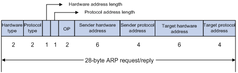
· Hardware type—Hardware address type. The value 1 represents Ethernet.
· Protocol type—Type of the protocol address to be mapped. The hexadecimal value 0x0800 represents IP.
· Hardware address length and protocol address length—Length, in bytes, of a hardware address and a protocol address. For an Ethernet address, the value of the hardware address length field is 6. For an IPv4 address, the value of the protocol address length field is 4.
· OP—Operation code, which describes the type of ARP message. Value 1 represents an ARP request, and value 2 represents an ARP reply.
· Sender hardware address—Hardware address of the device sending the message.
· Sender protocol address—Protocol address of the device sending the message.
· Target hardware address—Hardware address of the device to which the message is being sent.
· Target protocol address—Protocol address of the device to which the message is being sent.
ARP operating mechanism
As shown in Figure 2, Host A and Host B are on the same subnet. Host A sends a packet to Host B as follows:
1. Host A looks through the ARP table for an ARP entry for Host B. If one entry is found, Host A uses the MAC address in the entry to encapsulate the IP packet into a data link layer frame. Then Host A sends the frame to Host B.
2. If Host A finds no entry for Host B, Host A buffers the packet and broadcasts an ARP request. The payload of the ARP request contains the following information:
? Sender IP address and sender MAC address—Host A's IP address and MAC address.
? Target IP address—Host B's IP address.
? Target MAC address—An all-zero MAC address.
All hosts on this subnet can receive the broadcast request, but only the requested host (Host B) processes the request.
3. Host B compares its own IP address with the target IP address in the ARP request. If they are the same, Host B:
a. Adds the sender IP address and sender MAC address into its ARP table.
b. Encapsulates its MAC address into an ARP reply.
c. Unicasts the ARP reply to Host A.
4. After receiving the ARP reply, Host A:
a. Adds the MAC address of Host B into its ARP table.
b. Encapsulates the MAC address into the packet and sends the packet to Host B.
Figure 2 ARP address resolution process

If Host A and Host B are on different subnets, Host A sends a packet to Host B as follows:
5. Host A broadcasts an ARP request where the target IP address is the IP address of the gateway.
6. The gateway responds with its MAC address in an ARP reply to Host A.
7. Host A uses the gateway's MAC address to encapsulate the packet, and then sends the packet to the gateway.
8. If the gateway has an ARP entry for Host B, it forwards the packet to Host B directly. If not, the gateway broadcasts an ARP request, in which the target IP address is the IP address of Host B.
9. After the gateway gets the MAC address of Host B, it sends the packet to Host B.
ARP table
An ARP table stores dynamic and static ARP entries.
Dynamic ARP entry
ARP automatically creates and updates dynamic entries. A dynamic ARP entry is removed when its aging timer expires or the output interface goes down. In addition, a dynamic ARP entry can be overwritten by a static ARP entry.
Static ARP entry
A static ARP entry is manually configured and maintained. It does not age out and cannot be overwritten by any dynamic ARP entry.
Static ARP entries protect communication between devices because attack packets cannot modify the IP-to-MAC mapping in a static ARP entry.
The device supports the following types of static ARP entries:
· Long static ARP entry—It contains the IP address, MAC address, VLAN, and output interface. It is directly used for forwarding packets.
· Short static ARP entry—It contains only the IP address and MAC address.
? If the output interface is a Layer 3 Ethernet interface, the short ARP entry can be directly used to forward packets.
? If the output interface is a VLAN interface, the device first sends an ARP request whose target IP address is the IP address of the short entry. If the sender IP and MAC addresses in the received ARP reply match the IP and MAC addresses of the short static ARP entry, the device adds the interface that received the ARP reply to the short static ARP entry, and uses the resolved short static ARP entry to forward IP packets.
· Multiport ARP entry—It contains the IP address, MAC address, and VLAN.
If a multiport ARP entry has the same MAC address and VLAN as a multicast or multiport unicast MAC address entry, the device can use the multiport ARP entry to send IP packets. A multiport ARP entry is manually configured. It does not age out and cannot be overwritten by any dynamic ARP entry. For more information about multicast MAC, see IP Multicast Configuration Guide.
To communicate with a host by using a fixed IP-to-MAC mapping, configure a short static ARP entry on the device. To communicate with a host by using a fixed IP-to-MAC mapping through an interface in a VLAN, configure a long static ARP entry on the device.
OpenFlow ARP entry
ARP creates OpenFlow ARP entries by learning from the OpenFlow module. An OpenFlow ARP entry does not age out, and it cannot be updated. An OpenFlow ARP entry can be used directly to forward packets. For more information about OpenFlow, see OpenFlow Configuration Guide.
Rule ARP entry
ARP creates Rule ARP entries by learning from the VXLAN and OVSDB modules. A Rule ARP entry does not age out, and it cannot be updated. It can be overwritten by a static ARP entry. A Rule ARP entry can be used directly to forward packets. For more information about VXLAN and OVSDB, see VXLAN Configuration Guide.
Configuring a static ARP entry
A static ARP entry is effective when the device functions correctly. If a VLAN or VLAN interface is deleted, any long static ARP entry in the VLAN is deleted, and any resolved short static ARP entry in the VLAN becomes unresolved.
A resolved short static ARP entry becomes unresolved upon certain events, for example, when the resolved output interface goes down.
A long static ARP entry is ineffective if the IP address in the entry conflicts with a local IP address, or no local interface has an IP address in the same subnet as the IP address in the ARP entry. An ineffective long static ARP entry cannot be used to forward packets.
Follow these guidelines when you configure a static ARP entry:
· The vlan-id argument must be the ID of an existing VLAN where the ARP entry resides. The specified Ethernet interface must belong to that VLAN. The VLAN interface of the VLAN must be created.
· The IP address of the VLAN interface of the VLAN specified by the vlan-id argument must belong to the same subnet as the IP address specified by the ip-address argument.
To configure a static ARP entry:
|
Step |
Command |
Remarks |
|
1. Enter system view. |
system-view |
N/A |
|
2. Configure a static ARP entry. |
·
Configure a long static ARP entry: ·
Configure a short static ARP entry: |
By default, no static ARP entry is configured. |
Configuring a multiport ARP entry
A multiport ARP entry contains an IP address, MAC address, and VLAN ID. To make the multiport ARP entry effective for packet forwarding, you must configure a multicast or multiport unicast MAC address entry to specify multiple output interfaces. The MAC address entry must have the same MAC address and VLAN ID as the multiport ARP entry. In addition, the IP address in the multiport ARP entry must reside on the same subnet as the virtual interface of the specified VLAN.
A multiport ARP entry can overwrite a dynamic, short static or long static ARP entry. Conversely, a short static or long static ARP entry can overwrite a multiport ARP entry.
To configure a multiport ARP entry:
|
Step |
Command |
Remarks |
|
3. Enter system view. |
system-view |
N/A |
|
4. Configure a multicast or multiport unicast MAC address entry. |
·
Configure a multiport unicast MAC address
entry: ·
Configure a multicast MAC address entry: |
By default, no multicast or multiport unicast MAC address entries are configured. For more information about the mac-address multiport command, see Layer 2—LAN Switching Command Reference. For more information about the mac-address multicast command, see IP Multicast Command Reference. |
|
5. Configure a multiport ARP entry. |
arp multiport ip-address mac-address vlan-id [ vpn-instance vpn-instance-name ] |
By default, no multiport ARP entries are configured. |
Setting the maximum number of dynamic ARP entries for a device
A device can dynamically learn ARP entries. To prevent a device from holding too many ARP entries, you can set the maximum number of dynamic ARP entries that the device can learn. When the maximum number is reached, the device stops learning ARP entries.
If you set a value lower than the number of existing dynamic ARP entries, the device does not remove the existing entries unless they are aged out. The device also stops learning ARP entries until the number of dynamic ARP entries is below the configured value.
To set the maximum number of dynamic ARP entries for a device:
|
Step |
Command |
Remarks |
|
1. Enter system view. |
system-view |
N/A |
|
2. Set the maximum number of dynamic ARP entries for the device. |
·
In standalone mode: ·
In IRF mode: |
By default, a device can learn a maximum of 262144 dynamic ARP entries in versions earlier than Release 1138P01 and 524288 dynamic ARP entries in Release 1138P01 and later versions. If the value for the number argument is set to 0, the device is disabled from learning dynamic ARP entries. |
Setting the maximum number of dynamic ARP entries for an interface
An interface can dynamically learn ARP entries. To prevent an interface from holding too many ARP entries, you can set the maximum number of dynamic ARP entries that the interface can learn. When the maximum number is reached, the interface stops learning ARP entries.
The Layer-2 interface can learn an ARP entry only when both its maximum number and the VLAN interface's maximum number are not reached.
To set the maximum number of dynamic ARP entries for an interface:
|
Step |
Command |
Remarks |
|
1. Enter system view. |
system-view |
N/A |
|
2. Enter interface view. |
interface interface-type interface-number |
N/A |
|
3. Set the maximum number of dynamic ARP entries for the interface. |
arp max-learning-num number |
By default, an interface can learn a maximum of 262144 dynamic ARP entries in versions earlier than Release 1138P01 and 524288 dynamic ARP entries in Release 1138P01 and later versions. If the value of the number argument is set to 0, the interface is disabled from learning dynamic ARP entries. |
Setting the aging timer for dynamic ARP entries
Each dynamic ARP entry in the ARP table has a limited lifetime, called an aging timer. The aging timer of a dynamic ARP entry is reset each time the dynamic ARP entry is updated. A dynamic ARP entry that is not updated before its aging timer expires is deleted from the ARP table.
To set the aging timer for dynamic ARP entries:
|
Step |
Command |
Remarks |
|
1. Enter system view. |
system-view |
N/A |
|
2. Set the aging timer for dynamic ARP entries. |
arp timer aging aging-time |
By default, the aging time for dynamic ARP entries is 20 minutes. |
Enabling dynamic ARP entry check
The dynamic ARP entry check feature controls whether the device supports dynamic ARP entries containing multicast MAC addresses.
When dynamic ARP entry check is enabled, the device cannot learn dynamic ARP entries containing multicast MAC addresses, and you cannot manually add static ARP entries containing multicast MAC addresses.
When dynamic ARP entry check is disabled, the device can learn dynamic ARP entries containing multicast MAC addresses obtained from the ARP packets sourced from a unicast MAC address. You can also manually add static ARP entries containing multicast MAC addresses.
To enable dynamic ARP entry check:
|
Step |
Command |
Remarks |
|
1. Enter system view. |
system-view |
N/A |
|
2. Enable dynamic ARP entry check. |
arp check enable |
By default, dynamic ARP entry check is enabled. |
Configuring a customer-side port
By default, the device associates an ARP entry with routing information when the device learns an ARP entry. The ARP entry provides the next hop information for routing. To save hardware resources, you can use this command to specify a port that connects a user terminal as a customer-side port so the device will not associate the routing information with the learned ARP entries.
To configure a customer-side port:
|
Step |
Command |
Remarks |
|
1. Enter system view. |
system-view |
N/A |
|
2. Create a VLAN interface and enter its view. |
interface vlan-interface vlan-interface-id |
If the VLAN interface exists, you directly enter its view. |
|
3. Specify the VLAN interface as a customer-side port. |
arp mode uni |
By default, a port operates as a network-side port. |
Enabling ARP logging
This feature enables a device to log ARP events in ARP resolution.
To enable ARP logging:
|
Step |
Command |
Remarks |
|
1. Enter system view. |
system-view |
N/A |
|
2. Enable ARP logging. |
arp check log enable |
By default, ARP logging is disabled. |
Performing ARP entry synchronization
|
|
IMPORTANT: This feature is available in Release 1138P01 and later versions. |
This task ensures that all cards on the device have the same ARP entries. This task is a one-time operation.
To synchronize ARP entries across all cards in a timely manner, you can schedule the device to automatically execute the arp smooth command. For information about scheduling a task, see Fundamentals Configuration Guide.
To synchronize ARP entries from the active MPU to all other cards:
|
Task |
Command |
Remarks |
|
Synchronize ARP entries from the active MPU to all other cards. |
arp smooth |
This command is available in any view. |
Displaying and maintaining ARP
|
|
IMPORTANT: Clearing ARP entries from the ARP table might cause communication failures. Make sure the entries to be cleared do not affect current communications. |
Execute display commands in any view and reset commands in user view.
|
Task |
Command |
|
Display ARP entries (in standalone mode). |
display arp [ [ all | dynamic | multiport | static ] [ slot slot-number ] | vlan vlan-id | interface interface-type interface-number ] [ count | verbose ] |
|
Display ARP entries (in IRF mode). |
display arp [ [ all | dynamic | multiport | static ] [ chassis chassis-number slot slot-number ] | vlan vlan-id | interface interface-type interface-number ] [ count | verbose ] |
|
Display the ARP entry for an IP address (in standalone mode). |
display arp ip-address [ slot slot-number ] [ verbose ] |
|
Display the ARP entry for an IP address (in IRF mode). |
display arp ip-address [ chassis chassis-number slot slot-number ] [ verbose ] |
|
Display the ARP entries for a VPN instance. |
display arp vpn-instance vpn-instance-name [ count ] |
|
Display the aging timer of dynamic ARP entries. |
display arp timer aging |
|
Clear ARP entries from the ARP table (in standalone mode). |
reset arp { all | dynamic | interface interface-type interface-number | multiport | slot slot-number | static } |
|
Clear ARP entries from the ARP table (in IRF mode). |
reset arp { all | chassis chassis-number slot slot-number | dynamic | interface interface-type interface-number | multiport | static } |
Configuration examples
Static ARP configuration example
Network requirements
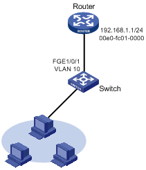
As shown in Figure 3, hosts are connected to the switch, which is connected to the router through interface FortyGigE 1/0/1 in VLAN 10.
To ensure secure communications between the router and switch, configure a static ARP entry for the router on the switch.
Configuration procedure
# Create VLAN 10.
<Switch> system-view
[Switch] vlan 10
[Switch-vlan10] quit
# Add interface FortyGigE 1/0/1 to VLAN 10.
[Switch] interface fortygige 1/0/1
[Switch-FortyGigE1/0/1] port access vlan 10
[Switch-FortyGigE1/0/1] quit
# Create VLAN-interface 10 and configure its IP address.
[Switch] interface vlan-interface 10
[Switch-vlan-interface10] ip address 192.168.1.2 24
[Switch-vlan-interface10] quit
# Configure a static ARP entry that has IP address 192.168.1.1, MAC address 00e0-fc01-0000, and output interface FortyGigE 1/0/1 in VLAN 10.
[Switch] arp static 192.168.1.1 00e0-fc01-0000 10 fortygige 1/0/1
Verifying the configuration
# Verify that the switch has a static ARP entry for the router. This verification example is applicable to Release 1135.
[Switch] display arp static
Type: S-Static D-Dynamic O-Openflow M-Multiport I-Invalid
IP address MAC address VLAN Interface Aging Type
192.168.1.1 00e0-fc01-0000 10 FGE1/0/1 N/A S
# Verify that the switch has a static ARP entry for the router. This verification example is applicable to Release 1138P01 and later versions.
[Switch] display arp static
Type: S-Static D-Dynamic O-Openflow R-Rule M-Multiport I-Invalid
IP address MAC address VID Interface/Link ID Aging Type
192.168.1.1 00e0-fc01-0000 10 FGE1/0/1 N/A S
Multiport ARP entry configuration example
Network requirements
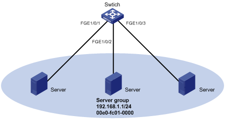
As shown in Figure 4, a switch connects to three servers through interfaces FortyGigE 1/0/1, FortyGigE 1/0/2, and FortyGigE 1/0/3 in VLAN 10. The servers share the IP address 192.168.1.1/24 and MAC address 00e0-fc01-0000.
Configure a multiport ARP entry to send IP packets with destination IP address 192.168.1.1 to the three servers.
Configuration procedure
# Create VLAN 10.
<Switch> system-view
[Switch] vlan 10
[Switch-vlan10] quit
# Add FortyGigE 1/0/1, FortyGigE 1/0/2, and FortyGigE 1/0/3 to VLAN 10.
[Switch] interface fortygige 1/0/1
[Switch-FortyGigE1/0/1] port access vlan 10
[Switch-FortyGigE1/0/1] quit
[Switch] interface fortygige 1/0/2
[Switch-FortyGigE1/0/2] port access vlan 10
[Switch-FortyGigE1/0/2] quit
[Switch] interface fortygige 1/0/3
[Switch-FortyGigE1/0/3] port access vlan 10
[Switch-FortyGigE1/0/3] quit
# Create VLAN-interface 10 and specify its IP address.
[Switch] interface vlan-interface 10
[Switch-vlan-interface10] ip address 192.168.1.2 24
[Switch-vlan-interface10] quit
# Configure a multiport unicast MAC address entry that has MAC address 00e0-fc01-0000, and output interfaces FortyGigE 1/0/1 through FortyGigE 1/0/3 in VLAN 10.
[Switch] mac-address multiport 00e0-fc01-0000 interface fortygige 1/0/1 to fortygige 1/0/3 vlan 10
# Configure a multiport ARP entry with IP address 192.168.1.1 and MAC address 00e0-fc01-0000.
[Switch] arp multiport 192.168.1.1 00e0-fc01-0000 10
Verifying the configuration
# Verify that the switch has a multiport ARP entry with IP address 192.168.1.1 and MAC address 00e0-fc01-0000. This verification example is applicable to Release 1135.
[Switch] display arp
Type: S-Static D-Dynamic O-Openflow M-Multiport I-Invalid
IP address MAC address VLAN Interface Aging Type
192.168.1.1 00e0-fc01-0000 10 N/A N/A M
# Verify that the switch has a multiport ARP entry with IP address 192.168.1.1 and MAC address 00e0-fc01-0000. This verification example is applicable to Release 1138P01 and later versions.
[Switch] display arp
Type: S-Static D-Dynamic O-Openflow R-Rule M-Multiport I-Invalid
IP address MAC address VID Interface/Link ID Aging Type
192.168.1.1 00e0-fc01-0000 10 N/A N/A M
Configuring gratuitous ARP
Overview
In a gratuitous ARP packet, the sender IP address and the target IP address are the IP address of the sending device.
A device sends a gratuitous ARP packet for either of the following purposes:
· Determine whether its IP address is already used by another device. If the IP address is already used, the device is informed of the conflict by an ARP reply.
· Inform other devices of a MAC address change.
Gratuitous ARP packet learning
This feature enables a device to create or update ARP entries by using the sender IP and MAC addresses in received gratuitous ARP packets.
When this feature is disabled, the device uses received gratuitous ARP packets to update existing ARP entries only.
Periodic sending of gratuitous ARP packets
Enabling a device to periodically send gratuitous ARP packets helps downstream devices update ARP entries or MAC entries in a timely manner. This feature can be used to prevent gateway spoofing, prevent ARP entries from aging out, and prevent the virtual IP address of a VRRP group from being used by a host.
· Prevent gateway spoofing.
An attacker can use the gateway address to send gratuitous ARP packets to the hosts on a network, so that the traffic destined for the gateway from the hosts is sent to the attacker instead. As a result, the hosts cannot access the external network.
To prevent such gateway spoofing attacks, you can enable the gateway to send gratuitous ARP packets at intervals. Gratuitous ARP packets contain the primary IP address and manually configured secondary IP addresses of the gateway, so hosts can learn correct gateway address information.
· Prevent ARP entries from aging out.
If network traffic is heavy or if the host CPU usage is high, received ARP packets can be discarded or are not promptly processed. Eventually, the dynamic ARP entries on the receiving host age out and the traffic between the host and the corresponding devices is interrupted until the host re-creates the ARP entries.
To prevent this problem, you can enable the gateway to send gratuitous ARP packets periodically. The gratuitous ARP packets contain the gateway's primary IP address or one of its manually configured secondary IP addresses, so the receiving hosts can update ARP entries in time.
· Prevent the virtual IP address of a VRRP group from being used by a host.
The master router of a VRRP group can periodically send gratuitous ARP packets to the hosts on the local network, so that the hosts can update local ARP entries and avoid using the virtual IP address of the VRRP group. For more information about VRRP, see High Availability Configuration Guide.
? If the virtual IP address of the VRRP group is associated with a virtual MAC address, the sender MAC address in the gratuitous ARP packet is the virtual MAC address of the virtual router.
? If the virtual IP address of the VRRP group is associated with the real MAC address of an interface, the sender MAC address in the gratuitous ARP packet is the MAC address of the interface on the master router in the VRRP group.
Configuration procedure
The following conditions apply to the gratuitous ARP configuration:
· You can enable periodic sending of gratuitous ARP packets on up to 1024 interfaces.
· Periodic sending of gratuitous ARP packets takes effect only when the link of the enabled interface goes up and an IP address has been assigned to the interface.
· If you change the interval for sending gratuitous ARP packets, the configuration is effective at the next sending interval.
· The frequency of sending gratuitous ARP packets might be much lower than the sending interval set by the user in any of the following circumstances:
? This feature is enabled on multiple interfaces.
? Each interface is configured with multiple secondary IP addresses.
? A small sending interval is configured when the previous two conditions exist.
To configure gratuitous ARP:
|
Step |
Command |
Remarks |
|
1. Enter system view. |
system-view |
N/A |
|
2. Enable learning of gratuitous ARP packets. |
gratuitous-arp-learning enable |
By default, learning of gratuitous ARP packets is enabled. |
|
3. Enable the device to send gratuitous ARP packets upon receiving ARP requests whose sender IP address belongs to a different subnet. |
gratuitous-arp-sending enable |
By default, a device does not send gratuitous ARP packets upon receiving ARP requests whose sender IP address belongs to a different subnet. |
|
4. Enter interface view. |
interface interface-type interface-number |
N/A |
|
5. Enable periodic sending of gratuitous ARP packets and set the sending interval. |
arp send-gratuitous-arp [ interval milliseconds ] |
By default, periodic sending of gratuitous ARP packets is disabled. |
Enabling IP conflict notification
By default, if the sender IP address of a gratuitous ARP packet is being used by the receiving device, the receiving device sends a gratuitous ARP request. It also displays an error message after it receives an ARP reply about the conflict.
You can use this command to enable the device to display error messages without sending a gratuitous ARP reply or request for conflict confirmation.
To enable IP conflict notification:
|
Step |
Command |
Remarks |
|
1. Enter system view. |
system-view |
N/A |
|
2. Enable IP conflict notification. |
arp ip-conflict log prompt |
By default, IP conflict notification is disabled. |
Configuring proxy ARP
Proxy ARP enables a device on one network to answer ARP requests for an IP address on another network. With proxy ARP, hosts on different broadcast domains can communicate with each other as they would on the same broadcast domain.
Proxy ARP includes common proxy ARP and local proxy ARP.
· Common proxy ARP—Allows communication between hosts that connect to different Layer-3 interfaces and reside in different broadcast domains.
· Local proxy ARP—Allows communication between hosts that connect to the same Layer-3 interface and reside in different broadcast domains.
Enabling common proxy ARP
|
Step |
Command |
Remarks |
|
1. Enter system view. |
system-view |
N/A |
|
2. Enter interface view. |
interface interface-type interface-number |
The following interface types are supported: · VLAN interface. · Layer 3 Ethernet interface. · Layer 3 Ethernet subinterface. · Layer 3 aggregate interface. · Layer 3 aggregate subinterface. |
|
3. Enable common proxy ARP. |
proxy-arp enable |
By default, common proxy ARP is disabled. |
Enabling local proxy ARP
|
Step |
Command |
Remarks |
|
1. Enter system view. |
system-view |
N/A |
|
2. Enter interface view. |
interface interface-type interface-number |
The following interface types are supported: · VLAN interface. · Layer 3 Ethernet interface. · Layer 3 Ethernet subinterface. · Layer 3 aggregate interface. · Layer 3 aggregate subinterface. |
|
3. Enable local proxy ARP. |
local-proxy-arp enable [ ip-range startIP to endIP ] |
By default, local proxy ARP is disabled. |
Displaying proxy ARP
Execute display commands in any view.
|
Task |
Command |
|
Display common proxy ARP status. |
display proxy-arp [ interface interface-type interface-number ] |
|
Display local proxy ARP status. |
display local-proxy-arp [ interface interface-type interface-number ] |
Common proxy ARP configuration example
Network requirements
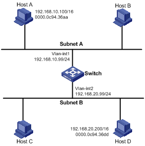
As shown in Figure 5, Host A and Host D have the same IP prefix and mask, but they are located on different subnets separated by the switch (Host A belongs to VLAN 1, and Host D belongs to VLAN 2). No default gateway is configured on Host A and Host D.
Configure common proxy ARP on the switch to enable communication between the two hosts.
Configuration procedure
# Create VLAN 2.
<Switch> system-view
[Switch] vlan 2
[Switch-vlan2] quit
# Configure the IP address of VLAN-interface 1.
[Switch] interface vlan-interface 1
[Switch-Vlan-interface1] ip address 192.168.10.99 255.255.255.0
# Enable common proxy ARP on VLAN-interface 1.
[Switch-Vlan-interface1] proxy-arp enable
[Switch-Vlan-interface1] quit
# Configure the IP address of VLAN-interface 2.
[Switch] interface vlan-interface 2
[Switch-Vlan-interface2] ip address 192.168.20.99 255.255.255.0
# Enable common proxy ARP on VLAN-interface 2.
[Switch-Vlan-interface2] proxy-arp enable
Verifying the configuration
# Verify that Host A and Host D can ping each other.
Configuring IP addressing
This chapter describes IP addressing basic and manual IP address assignment for interfaces. Dynamic IP address assignment (DHCP) is beyond the scope of this chapter. The IP addresses in this chapter refer to IPv4 addresses unless otherwise specified.
|
|
NOTE: The term "interface" in this chapter collectively refers to Layer 3 interfaces, including VLAN interfaces and Layer 3 Ethernet interfaces. You can set an Ethernet port as a Layer 3 interface by using the port link-mode route command (see Layer 2—LAN Switching Configuration Guide). |
Overview
This section describes the IP addressing basics.
IP addressing uses a 32-bit address to identify each host on an IPv4 network. To make addresses easier to read, they are written in dotted decimal notation, each address being four octets in length. For example, address 00001010000000010000000100000001 in binary is written as 10.1.1.1.
IP address classes
Each IP address breaks down into the following sections:
· Net ID—Identifies a network. The first several bits of a net ID, known as the class field or class bits, identify the class of the IP address.
· Host ID—Identifies a host on a network.
IP addresses are divided into five classes, as shown in Figure 6. The shaded areas represent the address class. The first three classes are most commonly used.
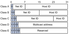
Table 1 IP address classes and ranges
|
Class |
Address range |
Remarks |
|
A |
0.0.0.0 to 127.255.255.255 |
The IP address 0.0.0.0 is used by a host at startup for temporary communication. This address is never a valid destination address. Addresses starting with 127 are reserved for loopback test. Packets destined to these addresses are processed locally as input packets rather than sent to the link. |
|
B |
128.0.0.0 to 191.255.255.255 |
N/A |
|
C |
192.0.0.0 to 223.255.255.255 |
N/A |
|
D |
224.0.0.0 to 239.255.255.255 |
Multicast addresses. |
|
E |
240.0.0.0 to 255.255.255.255 |
Reserved for future use, except for the broadcast address 255.255.255.255. |
Special IP addresses
The following IP addresses are for special use and cannot be used as host IP addresses:
· IP address with an all-zero net ID—Identifies a host on the local network. For example, IP address 0.0.0.16 indicates the host with a host ID of 16 on the local network.
· IP address with an all-zero host ID—Identifies a network.
· IP address with an all-one host ID—Identifies a directed broadcast address. For example, a packet with the destination address of 192.168.1.255 will be broadcast to all the hosts on the network 192.168.1.0.
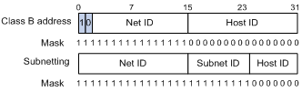
Subnetting and masking
Subnetting divides a network into smaller networks called subnets by using some bits of the host ID to create a subnet ID.
Masking identifies the boundary between the host ID and the combination of net ID and subnet ID.
Each subnet mask comprises 32 bits that correspond to the bits in an IP address. In a subnet mask, consecutive ones represent the net ID and subnet ID, and consecutive zeros represent the host ID.
Before being subnetted, Class A, B, and C networks use these default masks (also called natural masks): 255.0.0.0, 255.255.0.0, and 255.255.255.0, respectively.
Figure 7 Subnetting a Class B network
Subnetting increases the number of addresses that cannot be assigned to hosts. Therefore, using subnets means accommodating fewer hosts.
For example, a Class B network without subnetting can accommodate 1022 more hosts than the same network subnetted into 512 subnets.
· Without subnetting—65534 hosts (216 – 2). (The two deducted addresses are the broadcast address, which has an all-one host ID, and the network address, which has an all-zero host ID.)
· With subnetting—Using the first nine bits of the host-id for subnetting provides 512 (29) subnets. However, only seven bits remain available for the host ID. This allows 126 (27 – 2) hosts in each subnet, a total of 64512 hosts (512 × 126).
Assigning an IP address to an interface
An interface must have an IP address to communicate with other hosts. You can either manually assign an IP address to an interface, or configure the interface to obtain an IP address through DHCP. If you change the way an interface obtains an IP address, the new IP address will overwrite the previous address.
An interface can have one primary address and multiple secondary addresses.
Typically, you need to configure a primary IP address for an interface. If the interface connects to multiple subnets, configure primary and secondary IP addresses on the interface so the subnets can communicate with each other through the interface.
In an IRF fabric, you can assign an IP address to the management Ethernet port of each member in the management Ethernet port view of the master. Only the IP address assigned to the management Ethernet port of the master takes effect. After an IRF fabric split, the IP addresses assigned to the management Ethernet ports of the new masters (original subordinates) take effect. Then you can use these IP addresses to log in to the new masters for troubleshooting.
|
|
NOTE: After an IRF split, the routing information on the original master might not be updated immediately. As a result, the management Ethernet port of the original master cannot be pinged from the master (original subordinate) in another IRF fabric. To resolve the problem, wait until route synchronization between the devices is completed or enable NSR for the routing protocol. For information about NSR, see Layer 3—IP Routing Configuration Guide. |
Configuration guidelines
Follow these guidelines when you assign an IP address to an interface:
· An interface can have only one primary IP address. A newly configured primary IP address overwrites the previous one.
· You cannot assign secondary IP addresses to an interface that obtains an IP address through DHCP.
· The primary and secondary IP addresses assigned to the interface can be located on the same network segment. The following interfaces on the device must reside on different network segments:
? Different interfaces.
? Main interfaces and their subinterfaces.
? Subinterfaces of the same main interface.
· The following commands are mutually exclusive. You cannot configure all on the management Ethernet port of the IRF master.
? The ip address command with the irf-member member-id option that specifies the master.
? The ip address command that does not contain the irf-member member-id option.
? The mad ip address command.
? The ip address dhcp-alloc command.
· Exclude the management Ethernet port of the master from being shut down if MAD is enabled in the IRF fabric. The port can be kept in up state when the MAD status transits to Recovery.
Configuration procedure
To assign an IP address to an interface:
|
Step |
Command |
Remarks |
|
1. Enter system view. |
system-view |
N/A |
|
2. Enter interface view. |
interface interface-type interface-number |
N/A |
|
3. Assign an IP address to the interface. |
·
In standalone mode: ·
In IRF mode: |
By default, no IP address is assigned to the interface. To assign an IP address to the management Ethernet port of an IRF member device, enter the master's management Ethernet port view and specify the irf-member member-id option. The irf-member member-id option is available in Release 1138P01 and later versions. |
Displaying and maintaining IP addressing
Execute display commands in any view.
|
Task |
Command |
|
Display IP configuration and statistics for the specified or all Layer 3 interfaces. |
display ip interface [ interface-type interface-number ] |
|
Display brief IP configuration information for the specified or all Layer 3 interfaces. |
display ip interface [ interface-type [ interface-number ] ] brief |
IP address configuration example
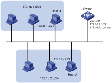
Network requirements
As shown in Figure 8, a port in VLAN 1 on a switch is connected to a LAN comprising two segments: 172.16.1.0/24 and 172.16.2.0/24.
To enable the hosts on the two network segments to communicate with the external network through the switch, and to enable the hosts on the LAN to communicate with each other:
· Assign a primary IP address and a secondary IP address to VLAN-interface 1 on the switch.
· Set the primary IP address of the switch as the gateway address of the PCs on subnet 172.16.1.0/24. Set the secondary IP address of the switch as the gateway address of the PCs on subnet 172.16.2.0/24.
Configuration procedure
# Assign a primary IP address and a secondary IP address to VLAN-interface 1.
<Switch> system-view
[Switch] interface vlan-interface 1
[Switch-Vlan-interface1] ip address 172.16.1.1 255.255.255.0
[Switch-Vlan-interface1] ip address 172.16.2.1 255.255.255.0 sub
# Set the gateway address to 172.16.1.1 on the PCs attached to subnet 172.16.1.0/24, and to 172.16.2.1 on the PCs attached to subnet 172.16.2.0/24.
Verifying the configuration
# Verify the connectivity between a host on subnet 172.16.1.0/24 and the switch.
<Switch> ping 172.16.1.2
Ping 172.16.1.2 (172.16.1.2): 56 data bytes, press CTRL_C to break
56 bytes from 172.16.1.2: icmp_seq=0 ttl=128 time=7.000 ms
56 bytes from 172.16.1.2: icmp_seq=1 ttl=128 time=2.000 ms
56 bytes from 172.16.1.2: icmp_seq=2 ttl=128 time=1.000 ms
56 bytes from 172.16.1.2: icmp_seq=3 ttl=128 time=1.000 ms
56 bytes from 172.16.1.2: icmp_seq=4 ttl=128 time=2.000 ms
--- Ping statistics for 172.16.1.2 ---
5 packet(s) transmitted, 5 packet(s) received, 0.0% packet loss
round-trip min/avg/max/std-dev = 1.000/2.600/7.000/2.245 ms
# Verify the connectivity between a host on subnet 172.16.2.0/24 and the switch.
<Switch> ping 172.16.2.2
Ping 172.16.2.2 (172.16.2.2): 56 data bytes, press CTRL_C to break
56 bytes from 172.16.2.2: icmp_seq=0 ttl=128 time=2.000 ms
56 bytes from 172.16.2.2: icmp_seq=1 ttl=128 time=7.000 ms
56 bytes from 172.16.2.2: icmp_seq=2 ttl=128 time=1.000 ms
56 bytes from 172.16.2.2: icmp_seq=3 ttl=128 time=2.000 ms
56 bytes from 172.16.2.2: icmp_seq=4 ttl=128 time=1.000 ms
--- Ping statistics for 172.16.2.2 ---
5 packet(s) transmitted, 5 packet(s) received, 0.0% packet loss
round-trip min/avg/max/std-dev = 1.000/2.600/7.000/2.245 ms
# Verify the connectivity between a host on subnet 172.16.1.0/24 and a host on subnet 172.16.2.0/24. The ping operation succeeds.
DHCP overview
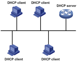
The Dynamic Host Configuration Protocol (DHCP) provides a framework to assign configuration information to network devices.
Figure 9 shows a typical DHCP application scenario where the DHCP clients and the DHCP server reside on the same subnet. The DHCP clients can also obtain configuration parameters from a DHCP server on another subnet through a DHCP relay agent. For more information about the DHCP relay agent, see "Configuring the DHCP relay agent."
Figure 9 A typical DHCP application
DHCP address allocation
Allocation mechanisms
DHCP supports the following allocation mechanisms:
· Static allocation—The network administrator assigns an IP address to a client, such as a WWW server, and DHCP conveys the assigned address to the client.
· Automatic allocation—DHCP assigns a permanent IP address to a client.
· Dynamic allocation—DHCP assigns an IP address to a client for a limited period of time, which is called a lease. Most DHCP clients obtain their addresses in this way.
IP address allocation process
Figure 10 IP address allocation process
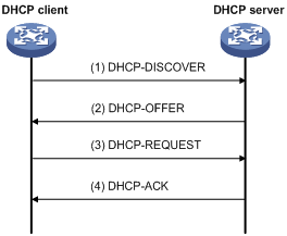
1. The client broadcasts a DHCP-DISCOVER message to locate a DHCP server.
2. Each DHCP server offers configuration parameters such as an IP address to the client in a DHCP-OFFER message. The sending mode of the DHCP-OFFER is determined by the flag field in the DHCP-DISCOVER message. For related information, see "DHCP message format."
3. If several DHCP servers send offers to the client, the client accepts the first received offer, and broadcasts it in a DHCP-REQUEST message to formally request the IP address. (IP addresses offered by other DHCP servers can be assigned to other clients.)
4. All DHCP servers receive the DHCP-REQUEST message, but only the server selected by the client returns a DHCP-ACK message to confirm that the IP address has been allocated to the client, or a DHCP-NAK message to deny the IP address allocation.
After receiving the DHCP-ACK message, the client verifies the following before using the assigned IP address:
· The assigned IP address is not in use. To verify this, it broadcasts a gratuitous ARP packet. The assigned IP address is not in use if no response is received within the specified time.
· The assigned IP address is not on the same subnet as any IP address in use on the client.
Otherwise, the client sends a DHCP-DECLINE message to the server to request an IP address again.
IP address lease extension
A dynamically assigned IP address has a lease. When the lease expires, the IP address is reclaimed by the DHCP server. To continue using the IP address, the client must extend the lease duration.
When half of the lease duration elapses, the DHCP client unicasts a DHCP-REQUEST to the DHCP server to extend the lease. Depending on the availability of the IP address, the DHCP server returns either a DHCP-ACK unicast confirming that the client's lease duration has been extended, or a DHCP-NAK unicast denying the request.
If the client receives no reply, it broadcasts another DHCP-REQUEST message for lease extension when seven eighths of the lease duration elapses. Again, depending on the availability of the IP address, the DHCP server returns either a DHCP-ACK unicast confirming that the client's lease duration has been extended, or a DHCP-NAK unicast denying the request.
DHCP message format
Figure 11 shows the DHCP message format. DHCP uses some of the fields in significantly different ways. The numbers in parentheses indicate the size of each field in bytes.
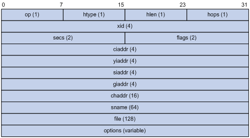
· op—Message type defined in options field. 1 = REQUEST, 2 = REPLY
· htype, hlen—Hardware address type and length of the DHCP client.
· hops—Number of relay agents a request message traveled.
· xid—Transaction ID, a random number chosen by the client to identify an IP address allocation.
· secs—Filled in by the client, the number of seconds elapsed since the client began address acquisition or renewal process. This field is reserved and set to 0.
· flags—The leftmost bit is defined as the BROADCAST (B) flag. If this flag is set to 0, the DHCP server sent a reply back by unicast. If this flag is set to 1, the DHCP server sent a reply back by broadcast. The remaining bits of the flags field are reserved for future use.
· ciaddr—Client IP address if the client has an IP address that is valid and usable. Otherwise, set to zero. (The client does not use this field to request a specific IP address to lease.)
· yiaddr—Your IP address. It is an IP address assigned by the DHCP server to the DHCP client.
· siaddr—Server IP address, from which the client obtained configuration parameters.
· giaddr—Gateway IP address. It is the IP address of the first relay agent that a request message travels.
· chaddr—Client hardware address.
· sname—Server host name, from which the client obtained configuration parameters.
· file—Boot file (also called system software image) name and path information, defined by the server to the client.
· options—Optional parameters field that is variable in length, which includes the message type, lease duration, subnet mask, domain name server IP address, and WINS IP address.
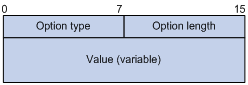
DHCP options
DHCP uses the same message format as BOOTP, but DHCP uses the options field to carry information for dynamic address allocation and provide additional configuration information to clients.
Figure 12 DHCP option format
Common DHCP options
The following are common DHCP options:
· Option 3—Router option. It specifies the gateway address.
· Option 6—DNS server option. It specifies the DNS server's IP address.
· Option 33—Static route option. It specifies a list of classful static routes (the destination network addresses in these static routes are classful) that a client should add into its routing table. If both Option 33 and Option 121 exist, Option 33 is ignored.
· Option 51—IP address lease option.
· Option 53—DHCP message type option. It identifies the type of the DHCP message.
· Option 55—Parameter request list option. It is used by a DHCP client to request specified configuration parameters. The option includes values that correspond to the parameters requested by the client.
· Option 60—Vendor class identifier option. It is used by a DHCP client to identify its vendor, and by a DHCP server to distinguish DHCP clients by vendor class and assign specific IP addresses to the DHCP clients.
· Option 66—TFTP server name option. It specifies a TFTP server to be assigned to the client.
· Option 67—Boot file name option. It specifies the boot file name to be assigned to the client.
· Option 121—Classless route option. It specifies a list of classless static routes (the destination network addresses in these static routes are classless) that the requesting client should add to its routing table. If both Option 33 and Option 121 exist, Option 33 is ignored.
· Option 150—TFTP server IP address option. It specifies the TFTP server IP address to be assigned to the client.
For more information about DHCP options, see RFC 2132 and RFC 3442.
Custom DHCP options
Some options, such as Option 43, Option 82, and Option 184, have no standard definitions in RFC 2132.
Vendor-specific option (Option 43)
DHCP servers and clients use Option 43 to exchange vendor-specific configuration information.
The DHCP client can obtain the following information through Option 43:
· ACS parameters, including the ACS URL, username, and password.
· Service provider identifier, which is acquired by the CPE from the DHCP server and sent to the ACS for selecting vender-specific configurations and parameters.
· PXE server address, which is used to obtain the boot file or other control information from the PXE server.
1. Format of Option 43:
Figure 13 Option 43 format
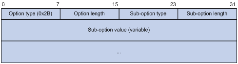
Network configuration parameters are carried in different sub-options of Option 43 as shown in Figure 13.
? Sub-option type—The field value can be 0x01 (ACS parameter sub-option), 0x02 (service provider identifier sub-option), or 0x80 (PXE server address sub-option).
? Sub-option length—Excludes the sub-option type and sub-option length fields.
? Sub-option value—The value format varies with sub-options.
2. Sub-option value field formats:
? ACS parameter sub-option value field—Includes the ACS URL, username, and password separated by spaces (0x20) as shown in Figure 14.
Figure 14 ACS parameter sub-option value field
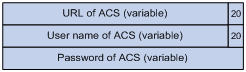
? Service provider identifier sub-option value field—Includes the service provider identifier.
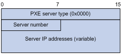
? PXE server address sub-option value field—Includes the PXE server type that can only be 0, the server number that indicates the number of PXE servers contained in the sub-option and server IP addresses, as shown in Figure 15.
Figure 15 PXE server address sub-option value field
Relay agent option (Option 82)
Option 82 is the relay agent option. It records the location information about the DHCP client. When a DHCP relay agent or DHCP snooping device receives a client's request, it adds Option 82 to the request message and sends it to the server.
The administrator can use Option 82 to locate the DHCP client and further implement security control and accounting. The DHCP server can use Option 82 to provide individual configuration policies for the clients.
Option 82 can include up to 255 sub-options and must have one sub-option at least. Option 82 supports two sub-options: sub-option 1 (Circuit ID) and sub-option 2 (Remote ID).
Option 82 has no standard definition. Its padding formats vary with vendors.
· Circuit ID has the following padding formats:
? String padding format—Includes a character string specified by the user.
? Normal padding format—Includes the VLAN ID and interface number of the interface that received the client's request.
? Verbose padding format—Includes the access node identifier specified by the user, and the VLAN ID, interface number and interface type of the interface that received the client's request.
· Remote ID has the following padding formats:
? String padding format—Includes a character string specified by the user.
? Normal padding format—Includes the MAC address of the DHCP relay agent interface or the MAC address of the DHCP snooping device that received the client's request.
? Sysname padding format—Includes the device name of the device. To set the device name for the device, use the sysname command in system view.
Option 184
Option 184 is a reserved option. You can define the parameters in the option as needed. The device supports Option 184 carrying voice related parameters, so a DHCP client with voice functions can get voice parameters from the DHCP server.
Option 184 has the following sub-options:
· Sub-option 1—Specifies the IP address of the primary network calling processor, which serves as the network calling control source and provides program download services. For Option 184, you must define sub-option 1 to make other sub-options take effect.
· Sub-option 2—Specifies the IP address of the backup network calling processor. DHCP clients contact the backup processor when the primary one is unreachable.
· Sub-option 3—Specifies the voice VLAN ID and the result whether or not the DHCP client takes this VLAN as the voice VLAN.
· Sub-option 4—Specifies the failover route that includes the IP address and the number of the target user. A SIP VoIP user uses this IP address and number to directly establish a connection to the target SIP user when both the primary and backup calling processors are unreachable.
Protocols and standards
· RFC 2131, Dynamic Host Configuration Protocol
· RFC 2132, DHCP Options and BOOTP Vendor Extensions
· RFC 1542, Clarifications and Extensions for the Bootstrap Protocol
· RFC 3046, DHCP Relay Agent Information Option
· RFC 3442, The Classless Static Route Option for Dynamic Host Configuration Protocol (DHCP) version 4
Configuring the DHCP server
Overview
The DHCP server is well suited to networks where:
· Manual configuration and centralized management are difficult to implement.
· IP addresses are limited. For example, an ISP limits the number of concurrent online users, and users must acquire IP addresses dynamically.
· Most hosts do not need fixed IP addresses.
An MCE serving as the DHCP server can assign IP addresses not only to clients on public networks, but also to clients on private networks. The IP address ranges of public and private networks or those of private networks on the DHCP server cannot overlap. For more information about MCE, see MCE Configuration Guide.
|
|
NOTE: The term "interface" in this section collectively refers to Layer 3 interfaces, including VLAN interfaces and Layer 3 Ethernet interfaces. You can set an Ethernet port as a Layer 3 interface by using the port link-mode route command (see Layer 2—LAN Switching Configuration Guide). |
DHCP address pool
Each DHCP address pool has a group of assignable IP addresses and network configuration parameters. The DHCP server selects IP addresses and other parameters from the address pool and assigns them to the DHCP clients.
Address assignment mechanisms
Configure the following address assignment mechanisms as needed:
· Static address allocation—Manually bind the MAC address or ID of a client to an IP address in a DHCP address pool. When the client requests an IP address, the DHCP server assigns the IP address in the static binding to the client.
· Dynamic address allocation—Specify IP address ranges in a DHCP address pool. Upon receiving a DHCP request, the DHCP server dynamically selects an IP address from the matching IP address range in the address pool.
There are two methods to specify IP address ranges in an address pool:
· Method 1—Specify a primary subnet in an address pool and divide the subnet into multiple address ranges, which include a common IP address range and IP address ranges for DHCP user classes.
Upon receiving a DHCP request, the DHCP server finds a user class matching the client and selects an IP address in the address range of the user class for the client. A user class can include multiple matching rules, and a client matches the user class as long as it matches any of the rules. In address pool view, you can specify different address ranges for different user classes.
DHCP selects an IP address for a client in the following order:
a. DHCP matches the client against DHCP user classes in the order they are configured.
b. If the client matches a user class, the DHCP server selects an IP address from the address range of the user class.
c. If the matching user class has no assignable addresses, the DHCP server matches the client against the next user class. If all the matching user classes have no assignable addresses, the DHCP server selects an IP address from the common address range.
d. If the DHCP client does not match any DHCP user class, the DHCP server selects an address in the IP address range specified by the address range command. If the address range has no assignable IP addresses or it is not configured, the address allocation fails.
|
|
NOTE: All address ranges must belong to the primary subnet. If an address range does not reside in the primary subnet, DHCP cannot assign the addresses in the address range. |
· Method 2—Specify a primary subnet and multiple secondary subnets in an address pool.
The DHCP server selects an IP address from the primary subnet first. If there is no assignable IP address in the primary subnet, the DHCP server selects an IP address from secondary subnets in the order they are configured.
Principles for selecting an address pool
The DHCP server observes the following principles to select an address pool for a client:
1. If there is an address pool where an IP address is statically bound to the MAC address or ID of the client, the DHCP server selects this address pool and assigns the statically bound IP address and other configuration parameters to the client.
2. If the receiving interface has an address pool applied, the DHCP server selects an IP address and other configuration parameters from this address pool.
3. If there is no static address pool and the receiving interface has no address pool applied, the DHCP server selects an address pool in the following way:
? If the client and the server reside on the same subnet, the DHCP server matches the IP address of the receiving interface against the primary subnets of all address pools, and selects the address pool with the longest-matching primary subnet. If no matching primary subnet is found, the DHCP server matches the IP address against the secondary subnets of all address pools, and selects the address pool with the longest-matching secondary subnet.
? If the client and the server reside on different subnets (a DHCP relay agent is in-between), the DHCP server matches the IP address in the giaddr field of the DHCP request against the primary subnets of all address pools, and selects the address pool with the longest-matching primary subnet. If no matching primary subnet is found, the DHCP server matches the IP address against the secondary subnets of all address pools, and selects the address pool with the longest-matching secondary subnet.
For example, two address pools 1.1.1.0/24 and 1.1.1.0/25 are configured on the DHCP server. If the IP address of the interface receiving DHCP requests is 1.1.1.1/25 and no address pool is applied on the interface, the DHCP server selects IP addresses for clients from the address pool 1.1.1.0/25. If no IP address is available in the address pool, the DHCP server fails to assign addresses. If the IP address of the receiving interface is 1.1.1.130/25, the DHCP server selects IP addresses for clients from the address pool 1.1.1.0/24.
|
|
NOTE: To make sure correct address allocation, keep the IP addresses used for dynamic allocation in the subnet where the interface of the DHCP server or DHCP relay agent resides as possible as you can. |
IP address allocation sequence
The DHCP server selects an IP address for a client in the following sequence:
1. IP address statically bound to the client's MAC address or ID.
2. IP address that was ever assigned to the client.
3. IP address designated by the Option 50 field in the DHCP-DISCOVER message sent by the client.
Option 50 is the Requested IP Address option. The client uses this option to specify the wanted IP address in a DHCP-DISCOVER message. The content of Option 50 is user defined.
4. First assignable IP address found in the way discussed in "DHCP address pool."
5. IP address that was a conflict or passed its lease duration. If no IP address is assignable, the server does not respond.
|
|
NOTE: If a client moves to another subnet, the DHCP server selects an IP address in the address pool matching the new subnet instead of assigning the IP address that was once assigned to the client. |
DHCP server configuration task list
|
Tasks at a glance |
|
(Required.) Configuring an address pool on the DHCP server |
|
(Required.) Enabling DHCP |
|
(Required.) Enabling the DHCP server on an interface |
|
(Optional.) Applying an address pool on an interface |
|
(Optional.) Configuring IP address conflict detection |
|
(Optional.) Enabling handling of Option 82 |
|
(Optional.) Configuring DHCP server compatibility |
|
(Optional.) Setting the DSCP value for DHCP packets sent by the DHCP server |
|
(Optional.) Applying a DHCP address pool to a VPN instance |
Configuring an address pool on the DHCP server
Configuration task list
Creating a DHCP address pool
|
Step |
Command |
Remarks |
|
1. Enter system view. |
system-view |
N/A |
|
2. Create a DHCP address pool and enter its view. |
dhcp server ip-pool pool-name |
By default, no DHCP address pool is created. |
Specifying IP address ranges for a DHCP address pool
You can configure both static and dynamic address allocation mechanisms in a DHCP address pool. For dynamic address allocation, you can specify either a primary subnet with multiple address ranges or a primary subnet with multiple secondary subnets for a DHCP address pool, but you cannot configure both.
Specifying a primary subnet and multiple address ranges for a DHCP address pool
Some scenarios need to classify DHCP clients in the same subnet into different address groups. To meet this need, you can configure DHCP user classes and specify different address ranges for the classes so that the clients matching a user class get the IP addresses of a specific address range. In addition, you can specify a common address range for the clients that do not match any user class. If no common address range is specified, such clients fail to obtain IP addresses.
If there is no need to classify clients, you do not need to configure DHCP user classes or their address ranges.
Follow these guidelines when you specify a primary subnet and multiple address ranges for a DHCP address pool:
· If you use the network or address range command multiple times for the same address pool, the most recent configuration takes effect.
· IP addresses specified by the forbidden-ip command are not assignable in the current address pool, but are assignable in other address pools. IP addresses specified by the dhcp server forbidden-ip command are not assignable in any address pool.
To specify a primary subnet and multiple address ranges for a DHCP address pool:
|
Step |
Command |
Remarks |
|
1. Enter system view. |
system-view |
N/A |
|
2. Create a DHCP user class and enter DHCP user class view. |
dhcp class class-name |
Required for client classification. By default, no DHCP user class exists. |
|
3. Configure the match rule for the DHCP user class. |
if-match rule rule-number option option-code [ hex hex-string [ offset offset length length | mask mask ] ] |
Required for client classification. By default, no match rule is specified for a DHCP user class. |
|
4. Return to system view. |
quit |
N/A |
|
5. Enter address pool view. |
dhcp server ip-pool pool-name |
N/A |
|
6. Specify the primary subnet for the address pool. |
network network-address [ mask-length | mask mask ] |
By default, no primary subnet is specified. |
|
7. (Optional.) Specify the common address range. |
address range start-ip-address end-ip-address |
By default, no IP address range is specified. |
|
8. (Optional.) Specify an IP address range for a DHCP user class. |
class class-name range start-ip-address end-ip-address |
By default, no IP address range is specified for a user class. The DHCP user class must already exist. To specify address ranges for multiple DHCP user classes, repeat this step. |
|
9. (Optional.) Specify the address lease duration. |
expired { day day [ hour hour [ minute minute [ second second ] ] ] | unlimited } |
The default setting is 1 day. |
|
10. (Optional.) Exclude the specified IP addresses in the address pool from dynamic allocation. |
forbidden-ip ip-address&<1-8> |
By default, all the IP addresses in the DHCP address pool are assignable. To exclude multiple address ranges from dynamic allocation, repeat this step. |
|
11. Return to system view. |
quit |
N/A |
|
12. (Optional.) Exclude the specified IP addresses from automatic allocation globally. |
dhcp server forbidden-ip start-ip-address [ end-ip-address ] [ vpn-instance vpn-instance-name ] |
By default, except for the IP address of the DHCP server interface, all IP addresses in address pools are assignable. To exclude multiple IP address ranges, repeat this step. The vpn-instance vpn-instance-name option is available in Release 1138P01 and later versions. |
Specifying a primary subnet and multiple secondary subnets for a DHCP address pool
In scenarios where the DHCP server and the DHCP clients reside on the same subnet, the DHCP server needs to assign addresses in different address ranges to the DHCP clients. To meet this need, you can specify a primary subnet and multiple secondary subnets in an address pool. Upon receiving a client request, the DHCP server selects an address from the primary subnet. If no assignable address is found, the server selects an address from the secondary subnets in the order they are configured.
In scenarios where the DHCP server and the DHCP clients reside on different subnets and the DHCP clients obtain IP addresses through a DHCP relay agent, the DHCP server needs to use the same address pool to assign IP addresses to clients in different subnets. To meet this need, you can specify a primary subnet and multiple secondary subnets in a DHCP address pool, which are consistent with the subnets where the relay agent interfaces reside. Upon receiving a DHCP request forwarded by a relay agent, the DHCP server reads the giaddr field in the request to find the corresponding subnet and selects an IP address for the client.
Follow these guidelines when you specify a primary subnet and secondary subnets for a DHCP address pool:
· You can specify only one primary subnet in each address pool. If you use the network command multiple times, the most recent configuration takes effect.
· You can specify a maximum of 32 secondary subnets in each address pool.
· IP addresses specified by the forbidden-ip command are not assignable in the current address pool, but are assignable in other address pools. IP addresses specified by the dhcp server forbidden-ip command are not assignable in any address pool.
To specify a primary subnet and secondary subnets for a DHCP address pool:
|
Step |
Command |
Remarks |
|
1. Enter system view. |
system-view |
N/A |
|
2. Enter address pool view. |
dhcp server ip-pool pool-name |
N/A |
|
3. Specify the primary subnet. |
network network-address [ mask-length | mask mask ] |
By default, no primary subnet is specified. |
|
4. (Optional.) Specify a secondary subnet. |
network network-address [ mask-length | mask mask ] secondary |
By default, no secondary subnet is specified. |
|
5. (Optional.) Return to address pool view. |
quit |
N/A |
|
6. (Optional.) Specify the address lease duration. |
expired { day day [ hour hour [ minute minute [ second second ] ] ] | unlimited } |
The default setting is 1 day. |
|
7. (Optional.) Exclude the specified IP addresses from dynamic allocation. |
forbidden-ip ip-address&<1-8> |
By default, all the IP addresses in the DHCP address pool can be dynamically allocated. To exclude multiple address ranges from the address pool, repeat this step. |
|
8. Return to system view. |
quit |
N/A |
|
9. (Optional.) Exclude the specified IP addresses from dynamic allocation globally. |
dhcp server forbidden-ip start-ip-address [ end-ip-address ] |
Except for the IP address of the DHCP server interface, IP addresses in all address pools are assignable by default. To exclude multiple address ranges globally, repeat this step. |
Configuring a static binding in a DHCP address pool
Some DHCP clients, such as a WWW server, need fixed IP addresses. To provide a fixed IP address for such a client, you can statically bind the MAC address or ID of the client to an IP address in a DHCP address pool. When the client requests an IP address, the DHCP server assigns the IP address in the static binding to the client.
Follow these guidelines when you configure a static binding:
· One IP address can be bound to only one client MAC or client ID. You cannot modify bindings that have been created. To change the binding for a DHCP client, you must delete the existing binding first.
· The IP address of a static binding cannot be the address of the DHCP server interface. Otherwise, an IP address conflict occurs and the bound client cannot obtain an IP address correctly.
· To configure static bindings for DHCP clients that reside on the same device and use the same MAC address, you must specify the client ID rather than the MAC address to identify a requesting interface. Otherwise, IP address allocation will fail.
To configure a static binding:
|
Step |
Command |
Remarks |
|
1. Enter system view. |
system-view |
N/A |
|
2. Enter address pool view. |
dhcp server ip-pool pool-name |
N/A |
|
3. Configure a static binding. |
static-bind ip-address ip-address [ mask-length | mask mask ] { client-identifier client-identifier | hardware-address hardware-address [ ethernet | token-ring ] } |
By default, no static binding is configured. To add more static bindings, repeat this step. |
|
4. (Optional.) Specify the lease duration for the IP address. |
expired { day day [ hour hour [ minute minute [ second second ] ] ] | unlimited } |
The default setting is 1 day. |
Specifying gateways for DHCP clients
DHCP clients send packets destined for other networks to a gateway. The DHCP server can assign the gateway address to the DHCP clients.
You can specify gateway addresses in each address pool on the DHCP server. A maximum of eight gateways can be specified in DHCP address pool view or secondary subnet view.
If you specify gateways in both address pool view and secondary subnet view, DHCP assigns the gateway addresses in the secondary subnet view to the clients on the secondary subnet. If you specify gateways in address pool view but not in secondary subnet view, DHCP assigns the gateway addresses in address pool view to the clients on the secondary subnet.
To configure gateways in the DHCP address pool:
|
Step |
Command |
Remarks |
|
1. Enter system view. |
system-view |
N/A |
|
2. Enter DHCP address pool view. |
dhcp server ip-pool pool-name |
N/A |
|
3. Specify gateways. |
gateway-list ip-address&<1-8> |
By default, no gateway is specified. |
|
4. (Optional.) Enter secondary subnet view |
network network-address [ mask-length | mask mask ] secondary |
N/A |
|
5. (Optional.) Specify gateways. |
gateway-list ip-address&<1-8> |
By default, no gateway is specified. |
Specifying a domain name suffix for DHCP clients
You can specify a domain name suffix in a DHCP address pool on the DHCP server. With this suffix assigned, the client only needs to input part of a domain name, and the system adds the domain name suffix for name resolution. For more information about DNS, see "Configuring IPv4 DNS."
To configure a domain name suffix in the DHCP address pool:
|
Step |
Command |
Remarks |
|
1. Enter system view. |
system-view |
N/A |
|
2. Enter DHCP address pool view. |
dhcp server ip-pool pool-name |
N/A |
|
3. Specify a domain name suffix. |
domain-name domain-name |
By default, no domain name is specified. |
Specifying DNS servers for DHCP clients
To access hosts on the Internet through domain names, a DHCP client must contact a DNS server to resolve names. You can specify up to eight DNS servers in a DHCP address pool.
To specify DNS servers in a DHCP address pool:
|
Step |
Command |
Remarks |
|
1. Enter system view. |
system-view |
N/A |
|
2. Enter DHCP address pool view. |
dhcp server ip-pool pool-name |
N/A |
|
3. Specify DNS servers. |
dns-list ip-address&<1-8> |
By default, no DNS server is specified. |
Specifying WINS servers and NetBIOS node type for DHCP clients
A Microsoft DHCP client using NetBIOS protocol must contact a WINS server for name resolution. You can specify up to eight WINS servers for such clients in a DHCP address pool.
In addition, you must specify a NetBIOS node type for the clients to approach name resolution. There are four NetBIOS node types:
· b (broadcast)-node—A b-node client sends the destination name in a broadcast message. The destination returns its IP address to the client after receiving the message.
· p (peer-to-peer)-node—A p-node client sends the destination name in a unicast message to the WINS server and the WINS server returns the destination IP address.
· m (mixed)-node—An m-node client broadcasts the destination name. If it receives no response, it unicasts the destination name to the WINS server to get the destination IP address.
· h (hybrid)-node—An h-node client unicasts the destination name to the WINS server. If it receives no response, it broadcasts the destination name to get the destination IP address.
To configure WINS servers and NetBIOS node type in a DHCP address pool:
|
Step |
Command |
Remarks |
|
1. Enter system view. |
system-view |
N/A |
|
2. Enter DHCP address pool view. |
dhcp server ip-pool pool-name |
N/A |
|
3. Specify WINS servers. |
nbns-list ip-address&<1-8> |
This step is optional for b-node. By default, no WINS server is specified. |
|
4. Specify the NetBIOS node type. |
netbios-type { b-node | h-node | m-node | p-node } |
By default, no NetBIOS node type is specified. |
Specifying BIMS server for DHCP clients
Perform this task to provide the BIMS server IP address, port number, and shared key for the clients. The DHCP clients contact the BIMS server to get configuration files and perform software upgrade and backup.
To configure the BIMS server IP address, port number, and shared key in the DHCP address pool:
|
Step |
Command |
Remarks |
|
1. Enter system view. |
system-view |
N/A |
|
2. Enter DHCP address pool view. |
dhcp server ip-pool pool-name |
N/A |
|
3. Specify the BIMS server IP address, port number, and shared key. |
bims-server ip ip-address [ port port-number ] sharekey { cipher | simple } key |
By default, no BIMS server information is specified. |
Specifying the configuration file for DHCP client auto-configuration
To implement client auto-configuration, you do not need to perform configuration on DHCP clients, but specify either of the following for clients on the DHCP server:
· The IP address or name of a TFTP server, and the boot file name.
· The remote boot file URL.
A DHCP client obtains these parameters from the DHCP server, and uses them to contact the TFTP server to get the configuration file used for system initialization. Auto-configuration operates as follows:
1. When a device starts up without loading any configuration file, it sets an active interface (such as the interface of the default VLAN or a Layer 3 Ethernet interface) as the DHCP client to get the following information from the DHCP server:
? An IP address.
? Parameters for configuration file acquisition.
The parameters include the TFTP server address or name and the boot file name, or the remote boot file URL.
2. After getting the information, the DHCP client sends a TFTP or HTTP request to obtain the configuration file from the specified TFTP or HTTP server for system initialization. If the client does not get the information, it restarts auto-configuration in 30 seconds. You can terminate the auto-configuration manually.
To specify the TFTP server and boot file name in a DHCP address pool:
|
Step |
Command |
Remarks |
|
1. Enter system view. |
system-view |
N/A |
|
2. Enter DHCP address pool view. |
dhcp server ip-pool pool-name |
N/A |
|
3. Specify the IP address or the name of a TFTP server. |
·
Specify the IP address of the TFTP server: ·
Specify the name of the TFTP server: |
Execute at least one of the commands. By default, no TFTP server is specified. |
|
4. Specify the boot file name. |
bootfile-name bootfile-name |
By default, no boot file name is specified. |
To specify the remote boot file URL in a DHCP address pool:
|
Step |
Command |
Remarks |
|
1. Enter system view. |
system-view |
N/A |
|
2. Enter DHCP address pool view. |
dhcp server ip-pool pool-name |
N/A |
|
3. Specify the remote boot file URL. |
bootfile-name url |
By default, no remote boot file URL is specified. |
Specifying a server for DHCP clients
Some DHCP clients need to obtain configuration information from a server, such as a TFTP server. You can specify the IP address of that server. The DHCP server sends the server's IP address to DHCP clients along with other configuration information.
To specify the IP address of a server:
|
Step |
Command |
Remarks |
|
1. Enter system view. |
system-view |
N/A |
|
2. Enter DHCP address pool view. |
dhcp server ip-pool pool-name |
N/A |
|
3. Specify the IP address of a server. |
next-server ip-address |
By default, no server is specified. |
Configuring Option 184 parameters for DHCP clients
To assign calling parameters to DHCP clients with voice service, you must configure Option 184 on the DHCP server. For more information about Option 184, see "Option 184."
To configure option 184 parameters in a DHCP address pool:
|
Step |
Command |
Remarks |
|
1. Enter system view. |
system-view |
N/A |
|
2. Enter DHCP address pool view. |
dhcp server ip-pool pool-name |
N/A |
|
3. Specify the IP address of the primary network calling processor. |
voice-config ncp-ip ip-address |
By default, no primary network calling processor is specified. After you configure this command, the other Option 184 parameters take effect. |
|
4. (Optional.) Specify the IP address for the backup server. |
voice-config as-ip ip-address |
By default, no backup network calling processor is specified. |
|
5. (Optional.) Configure the voice VLAN. |
voice-config voice-vlan vlan-id { disable | enable } |
By default, no voice VLAN is configured. |
|
6. (Optional.) Specify the failover IP address and dialer string. |
voice-config fail-over ip-address dialer-string |
By default, no failover IP address or dialer string is specified. |
Customizing DHCP options
|
|
IMPORTANT: Use caution when customizing DHCP options because the configuration might affect DHCP operation. |
You can customize options for the following purposes:
· Add newly released options.
· Add options for which the vendor defines the contents, for example, Option 43.
· Add options for which the CLI does not provide a dedicated configuration command. For example, you can use the option 4 ip-address 1.1.1.1 command to define the time server address 1.1.1.1 for DHCP clients.
· Add all option values if the actual requirement exceeds the limit for a dedicated option configuration command. For example, the dns-list command can specify up to eight DNS servers. To specify more than eight DNS servers, you must use the option 6 command to define all DNS servers.
To customize a DHCP option in a DHCP address pool:
|
Step |
Command |
Remarks |
|
1. Enter system view. |
system-view |
N/A |
|
2. Enter DHCP address pool view. |
dhcp server ip-pool pool-name |
N/A |
|
3. Customize a DHCP option. |
option code { ascii ascii-string | hex hex-string | ip-address ip-address&<1-8> } |
By default, no DHCP option is customized. |
|
Option |
Option name |
Corresponding command |
Recommended option command parameters |
|
3 |
Router Option |
gateway-list |
ip-address |
|
6 |
Domain Name Server Option |
dns-list |
ip-address |
|
15 |
Domain Name |
domain-name |
ascii |
|
44 |
NetBIOS over TCP/IP Name Server Option |
nbns-list |
ip-address |
|
46 |
NetBIOS over TCP/IP Node Type Option |
netbios-type |
hex |
|
66 |
TFTP server name |
tftp-server |
ascii |
|
67 |
Boot file name |
bootfile-name |
ascii |
|
43 |
Vendor Specific Information |
N/A |
hex |
Enabling DHCP
You must enable DHCP to validate other DHCP configurations.
To enable DHCP:
|
Step |
Command |
Remarks |
|
1. Enter system view. |
system-view |
N/A |
|
2. Enable DHCP. |
dhcp enable |
By default, DHCP is disabled. |
Enabling the DHCP server on an interface
Perform this task to enable the DHCP server on an interface. Upon receiving a DHCP request on the interface, the DHCP server assigns an IP address and other configuration parameters from the DHCP address pool to the DHCP client.
To enable the DHCP server on an interface:
|
Step |
Command |
Remarks |
|
1. Enter system view. |
system-view |
N/A |
|
2. Enter interface view. |
interface interface-type interface-number |
N/A |
|
3. Enable the DHCP server on the interface. |
dhcp select server |
By default, the DHCP server on the interface is enabled. |
Applying an address pool on an interface
Perform this task to apply a DHCP address pool on an interface. Upon receiving a DHCP request from the interface, the DHCP server assigns the statically bound IP address and configuration parameters from the address pool that contains the static binding. If no static binding is found for the requesting client, the DHCP server selects the applied address pool for address and configuration parameter allocation.
To apply an address pool on an interface:
|
Step |
Command |
Remarks |
|
1. Enter system view. |
system-view |
N/A |
|
2. Enter interface view. |
interface interface-type interface-number |
N/A |
|
3. Apply an address pool on the interface. |
dhcp server apply ip-pool pool-name |
By default, no address pool is applied on an interface. If the applied address pool does not exist, the DHCP server fails to perform dynamic address allocation. |
Configuring IP address conflict detection
Before assigning an IP address, the DHCP server pings that IP address.
· If the server receives a response within the specified period, it selects and pings another IP address.
· If it receives no response, the server continues to ping the IP address until a specific number of ping packets are sent. If still no response is received, the server assigns the IP address to the requesting client. The DHCP client uses gratuitous ARP to perform IP address conflict detection.
To configure IP address conflict detection:
|
Step |
Command |
Remarks |
|
1. Enter system view. |
system-view |
N/A |
|
2. (Optional.) Specify the maximum number of ping packets to be sent for conflict detection. |
dhcp server ping packets number |
The default setting is one. The value 0 disables IP address conflict detection. |
|
3. (Optional.) Configure the ping timeout time. |
dhcp server ping timeout milliseconds |
The default setting is 500 ms. The value 0 disables IP address conflict detection. |
Enabling handling of Option 82
If you disable the DHCP to handle Option 82, it does not add Option 82 into the response message.
You must enable handling of Option 82 on both the DHCP server and the DHCP relay agent to ensure correct processing for Option 82. For information about enabling handling of Option 82 on the DHCP relay agent, see "Configuring Option 82."
To enable the DHCP server to handle Option 82:
|
Step |
Command |
Remarks |
|
1. Enter system view. |
system-view |
N/A |
|
2. Enable the server to handle Option 82. |
dhcp server relay information enable |
By default, handling of Option 82 is enabled. |
Configuring DHCP server compatibility
Perform this task to enable the DHCP server to support DHCP clients that are incompliant with RFC.
Configuring the DHCP server to broadcast all responses
Typically, the DHCP server broadcasts a response only when the broadcast flag in the DHCP request is set to 1. To work with DHCP clients that set the broadcast flag to 0 but do not accept unicast responses, configure the DHCP server to ignore the broadcast flag and always broadcast a response.
If a DHCP request is from a DHCP client that has an IP address (the ciaddr field is not 0), the DHCP server always unicasts a response (the destination address is ciaddr) to the DHCP client regardless of whether this command is executed.
If a DHCP request is from a DHCP relay agent (the giaddr field is not 0), the DHCP server always unicasts a response (the destination address is giaddr) to the DHCP relay agent regardless of whether it is enabled to broadcast all responses.
To configure the DHCP server to broadcast all responses:
|
Step |
Command |
Remarks |
|
1. Enter system view. |
system-view |
N/A |
|
2. Enable the DHCP server to broadcast all responses. |
dhcp server always-broadcast |
By default, the DHCP server looks at the broadcast flag to decide whether to broadcast or unicast a response. |
Configure the DHCP server to ignore BOOTP requests
The lease duration of the IP addresses obtained by the BOOTP clients is unlimited. For some scenarios that do not allow unlimited leases, you can configure the DHCP server to ignore BOOTP requests.
To configure the DHCP server to ignore BOOTP requests:
|
Step |
Command |
Remarks |
|
1. Enter system view. |
system-view |
N/A |
|
2. Configure the DHCP server to ignore BOOTP requests. |
dhcp server bootp ignore |
By default, the DHCP server processes BOOTP requests. |
Configuring the DHCP server to send BOOTP responses in RFC 1048 format
Not all BOOTP clients can send requests that are compatible with RFC 1048. By default, the DHCP server does not process the Vend field of RFC 1048-incompliant requests but copies the Vend field into responses.
This feature enables the DHCP server to fill in the Vend field using the RFC 1048-compliant format in DHCP responses to RFC 1048-incompliant requests sent by BOOTP clients that request statically bound addresses.
To configure the DHCP server to send BOOTP responses in RFC 1048 format:
|
Step |
Command |
Remarks |
|
1. Enter system view. |
system-view |
N/A |
|
2. Enable the DHCP server to send BOOTP responses in RFC 1048 format to the RFC 1048-incompliant BOOTP requests for statically bound addresses. |
dhcp server bootp reply-rfc-1048 |
By default, the DHCP server directly copies the Vend field of such requests into the responses. |
Setting the DSCP value for DHCP packets sent by the DHCP server
The DSCP value of a packet specifies the priority level of the packet and affects the transmission priority of the packet.
To set the DSCP value for DHCP packets sent by the DHCP server:
|
Step |
Command |
Remarks |
|
1. Enter system view. |
system-view |
N/A |
|
2. Set the DSCP value for DHCP packets sent by the DHCP server. |
dhcp dscp dscp-value |
By default, the DSCP value in DHCP packets sent by the DHCP server is 56. |
Applying a DHCP address pool to a VPN instance
|
|
IMPORTANT: This feature is available in Release 1138P01 and later versions. |
If a DHCP address pool is applied to a VPN instance, the DHCP server assigns IP addresses in this address pool to clients in the VPN instance. Addresses in this address pool will not be assigned to clients on the public network.
The DHCP server can obtain the VPN instance to which a DHCP client belongs from the following information:
· The client's VPN information stored in authentication modules, such as IPoE.
· The VPN information of the DHCP server's interface that receives DHCP packets from the client.
The VPN information from authentication modules takes precedence over the VPN information of the receiving interface.
To apply a DHCP address pool to a VPN instance:
|
Step |
Command |
Remarks |
|
1. Enter system view. |
system-view |
N/A |
|
2. Create a DHCP address pool and enter its view. |
dhcp server ip-pool pool-name |
By default, no DHCP address pool exists. |
|
3. Apply the address pool to a VPN instance. |
vpn-instance vpn-instance-name |
By default, the address pool is not applied to any VPN instance. |
Displaying and maintaining the DHCP server
|
|
IMPORTANT: The vpn-instance vpn-instance-name option in the following commands is available in Release 1138P01 and later versions: · display dhcp server conflict. · display dhcp server expired. · display dhcp server free-ip. · display dhcp server ip-in-use. · display dhcp server statistics. · display dhcp server pool. · reset dhcp server conflict. · reset dhcp server expired. · reset dhcp server ip-in-use. · reset dhcp server statistics. A restart of the DHCP server or execution of the reset dhcp server ip-in-use command deletes all lease information. The DHCP server denies any DHCP request for lease extension, and the client must request an IP address again. |
Execute display commands in any view and reset commands in user view.
|
Task |
Command |
|
Display information about IP address conflicts. |
display dhcp server conflict [ ip ip-address ] [ vpn-instance vpn-instance-name ] |
|
Display information about lease-expired IP addresses. |
display dhcp server expired [ ip ip-address [ vpn-instance vpn-instance-name ] | pool pool-name ] |
|
Display information about assignable IP addresses. |
display dhcp server free-ip [ pool pool-name | vpn-instance vpn-instance-name ] |
|
Display information about assigned IP addresses. |
display dhcp server ip-in-use [ ip ip-address [ vpn-instance vpn-instance-name ] | pool pool-name ] |
|
Display DHCP server statistics. |
display dhcp server statistics [ pool pool-name | vpn-instance vpn-instance-name ] |
|
Display information about DHCP address pools. |
display dhcp server pool [ pool-name | vpn-instance vpn-instance-name ] |
|
Clear information about IP address conflicts. |
reset dhcp server conflict [ ip ip-address ] [ vpn-instance vpn-instance-name ] |
|
Clear information about lease-expired IP addresses. |
reset dhcp server expired [ ip ip-address [ vpn-instance vpn-instance-name ] | pool pool-name ] |
|
Clear information about assigned IP addresses. |
reset dhcp server ip-in-use [ ip ip-address [ vpn-instance vpn-instance-name ] | pool pool-name ] |
|
Clear DHCP server statistics. |
reset dhcp server statistics [ vpn-instance vpn-instance-name ] |
DHCP server configuration examples
DHCP networking involves the following types:
· The DHCP server and clients reside on the same subnet and exchange messages directly.
· The DHCP server and clients are not on the same subnet and they communicate with each other through a DHCP relay agent.
The DHCP server configuration for the two types is identical.
Static IP address assignment configuration example
Network requirements
As shown in Figure 16, Switch B (DHCP client) obtains the IP address, DNS server address, and gateway address from Switch A (DHCP server).
The client ID of VLAN-interface 2 on Switch B is:
0030-3030-662e-6532-3439-2e38-3035-302d-566c-616e-2d69-6e74-6572-6661-6365-32.
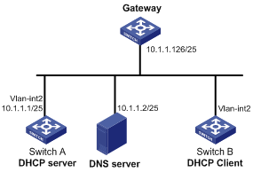
Configuration procedure
1. Specify an IP address for VLAN-interface 2 on Switch A:
<SwitchA> system-view
[SwitchA] interface vlan-interface 2
[SwitchA-Vlan-interface2] ip address 10.1.1.1 25
[SwitchA-Vlan-interface2] quit
2. Configure the DHCP server:
# Enable DHCP.
[SwitchA] dhcp enable
# Enable the DHCP server on VLAN-interface 2.
[SwitchA] interface vlan-interface 2
[SwitchA-Vlan-interface2] dhcp select server
[SwitchA-Vlan-interface2] quit
# Create DHCP address pool 0.
[SwitchA] dhcp server ip-pool 0
# Configure a static binding for DHCP client switch B.
[SwitchA-dhcp-pool-0] static-bind ip-address 10.1.1.5 25 client-identifier 0030-3030-662e-6532-3439-2e38-3035-302d-566c-616e-2d69-6e74-6572-6661-6365-32
# Specify the DNS server and gateway.
[SwitchA-dhcp-pool-0] dns-list 10.1.1.2
[SwitchA-dhcp-pool-0] gateway-list 10.1.1.126
[SwitchA-dhcp-pool-0] quit
Verifying the configuration
Switch B can obtain IP address 10.1.1.5 and other network parameters from Switch A. You can use the display dhcp server ip-in-use command on the DHCP server to display the IP addresses assigned to the client.
Dynamic IP address assignment configuration example
Network requirements
· As shown in Figure 17, the DHCP server (Switch A) assigns IP addresses to clients in subnet 10.1.1.0/24, which is subnetted into 10.1.1.0/25 and 10.1.1.128/25.
· The IP addresses of VLAN-interfaces 10 and 20 on Switch A are 10.1.1.1/25 and 10.1.1.129/25.
· In address pool 10.1.1.0/25, configure the address lease duration as ten days and twelve hours, domain name suffix aabbcc.com, DNS server address 10.1.1.2/25, gateway 10.1.1.126/25, and WINS server 10.1.1.4/25.
· In address pool 10.1.1.128/25, configure the address lease duration as five days, domain name suffix aabbcc.com, DNS server address 10.1.1.2/25, and gateway address 10.1.1.254/25, and there is no WINS server address.
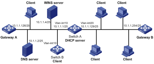
Configuration procedure
1. Specify IP addresses for the VLAN interfaces. (Details not shown.)
2. Configure the DHCP server:
# Enable DHCP.
<SwitchA> system-view
[SwitchA] dhcp enable
# Enable the DHCP server on VLAN-interface 10 and VLAN-interface 20.
[SwitchA] interface vlan-interface 10
[SwitchA-Vlan-interface10] dhcp select server
[SwitchA-Vlan-interface10] quit
[SwitchA] interface vlan-interface 20
[SwitchA-Vlan-interface20] dhcp select server
[SwitchA-Vlan-interface20] quit
# Exclude IP addresses (addresses of the DNS server, WINS server and gateways).
[SwitchA] dhcp server forbidden-ip 10.1.1.2
[SwitchA] dhcp server forbidden-ip 10.1.1.4
[SwitchA] dhcp server forbidden-ip 10.1.1.126
[SwitchA] dhcp server forbidden-ip 10.1.1.254
# Configure DHCP address pool 1 to assign IP addresses and other configuration parameters to clients in subnet 10.1.1.0/25.
[SwitchA] dhcp server ip-pool 1
[SwitchA-dhcp-pool-1] network 10.1.1.0 mask 255.255.255.128
[SwitchA-dhcp-pool-1] expired day 10 hour 12
[SwitchA-dhcp-pool-1] domain-name aabbcc.com
[SwitchA-dhcp-pool-1] dns-list 10.1.1.2
[SwitchA-dhcp-pool-1] gateway-list 10.1.1.126
[SwitchA-dhcp-pool-1] nbns-list 10.1.1.4
[SwitchA-dhcp-pool-1] quit
# Configure DHCP address pool 2 to assign IP addresses and other configuration parameters to clients in subnet 10.1.1.128/25.
[SwitchA] dhcp server ip-pool 2
[SwitchA-dhcp-pool-2] network 10.1.1.128 mask 255.255.255.128
[SwitchA-dhcp-pool-2] expired day 5
[SwitchA-dhcp-pool-2] domain-name aabbcc.com
[SwitchA-dhcp-pool-2] dns-list 10.1.1.2
[SwitchA-dhcp-pool-2] gateway-list 10.1.1.254
Verifying the configuration
After the preceding configuration is complete, clients on networks 10.1.1.0/25 and 10.1.1.128/25 can obtain correct IP addresses and other network parameters from Switch A. You can use the display dhcp server ip-in-use command on the DHCP server to display the IP addresses assigned to the clients.
DHCP user class configuration example
Network requirement
· The DHCP relay agent (Switch A) forwards the packets from DHCP clients to the DHCP server. Enable switch A to support Option 82 so that switch A can add Option 82 in the DHCP requests sent by the DHCP clients.
· The DHCP server (Switch B) assigns IP addresses and other configuration parameters to the DHCP clients. If the DHCP requests the DHCP server receives contain Option 82, the server assigns IP addresses in the range of 10.10.1.2 to 10.10.1.10 to the clients.
· For clients in subnet 10.10.1.0/24, the DNS server address is 10.10.1.20/24 and the gateway address is 10.10.1.255/24.
Figure 18 Network diagram
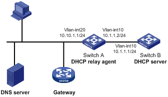
Configuration procedure
1. Specify IP addresses for interfaces on DHCP server and DHCP relay agent. (Details not shown.)
2. Configure DHCP services:
# Enable DHCP and configure the DHCP server to handle Option 82.
<SwitchB> system-view
[SwitchB] dhcp enable
[SwitchB] dhcp server relay information enable
# Enable DHCP server on VLAN-interface10.
[SwitchB] interface vlan-interface 10
[SwitchB-Vlan-interface10] dhcp select server
[SwitchB-Vlan-interface10] quit
# Create DHCP user class tt to match client requests with Option 82.
[SwitchB] dhcp class tt
[SwitchB-dhcp-class-tt] if-match option 82
[SwitchB-dhcp-class-tt] quit
# Create DHCP address pool aa, specify the address range for the address pool and the address range for user class tt. Specify gateway and DNS server address.
[SwitchB] dhcp server ip-pool aa
[SwitchB-dhcp-pool-aa] network 10.10.1.0 mask 255.255.255.0
[SwitchB-dhcp-pool-aa] address-range 10.10.1.2 10.10.1.100
[SwitchB-dhcp-pool-aa] class tt range 10.10.1.2 10.10.1.10
[SwitchB-dhcp-pool-aa] gateway-list 10.10.1.255
[SwitchB-dhcp-pool-aa] dns-list 10.10.1.20
Verifying the configuration
After the preceding configuration is complete, clients in a specific user class in subnet 10.10.1.0/24 can obtain IP addresses and other configuration parameters from the DHCP server (Switch B). Use the display dhcp server ip-in-use command to display the IP address assigned by the DHCP server.
DHCP option customization configuration example
Network requirements
As shown in Figure 19, the DHCP client (Switch B) obtains an IP address and PXE server addresses from the DHCP server (Switch A). The IP address belongs to subnet 10.1.1.0/24. The PXE server addresses are 1.2.3.4 and 2.2.2.2.
The DHCP server assigns PXE server addresses to DHCP clients through Option 43, a customized option. The format of Option 43 and that of the PXE server address sub-option are shown in Figure 13 and Figure 15. The value of Option 43 configured on the DHCP server in this example is 80 0B 00 00 02 01 02 03 04 02 02 02 02. The number 80 is the value of the sub-option type. The number 0B is the value of the sub-option length. The numbers 00 00 are the value of the PXE server type. The number 02 indicates the number of servers. The numbers 01 02 03 04 02 02 02 02 indicate that the PXE server addresses are 1.2.3.4 and 2.2.2.2.
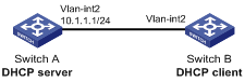
Configuration procedure
1. Specify IP addresses for the interfaces. (Details not shown.)
2. Configure the DHCP server:
# Enable DHCP.
<SwitchA> system-view
[SwitchA] dhcp enable
# Enable the DHCP server on VLAN-interface 2.
[SwitchA] interface vlan-interface 2
[SwitchA-Vlan-interface2] dhcp select server
[SwitchA-Vlan-interface2] quit
# Configure DHCP address pool 0.
[SwitchA] dhcp server ip-pool 0
[SwitchA-dhcp-pool-0] network 10.1.1.0 mask 255.255.255.0
[SwitchA-dhcp-pool-0] option 43 hex 800B0000020102030402020202
Verifying the configuration
After the preceding configuration is complete, Switch B can obtain its IP address on 10.1.1.0/24 and the PXE server addresses from the Switch A. You can use the display dhcp server ip-in-use command on the DHCP server to display the IP addresses assigned to the clients.
Troubleshooting DHCP server configuration
Symptom
A client's IP address obtained from the DHCP server conflicts with another IP address.
Analysis
Another host on the subnet might have the same IP address.
Solution
1. Disable the client's network adapter or disconnect the client's network cable. Ping the IP address of the client from another host to check whether there is a host using the same IP address.
2. If a ping response is received, the IP address has been manually configured on a host. Execute the dhcp server forbidden-ip command on the DHCP server to exclude the IP address from dynamic allocation.
3. Enable the network adapter or connect the network cable, release the IP address, and obtain another one on the client. For example, to release the IP address and obtain another one on a Windows XP DHCP client:
a. In Windows environment, execute the cmd command to enter the DOS environment.
b. Enter ipconfig /release to relinquish the IP address.
c. Enter ipconfig /renew to obtain another IP address.
Configuring the DHCP relay agent
Overview
The DHCP relay agent enables clients to get IP addresses from a DHCP server on another subnet. This feature avoids deploying a DHCP server for each subnet to centralize management and reduce investment. Figure 20 shows a typical application of the DHCP relay agent.
Figure 20 DHCP relay agent application
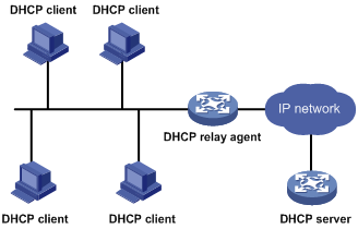
An MCE device serving as the DHCP relay agent can forward DHCP packets between a DHCP server and clients on either a public network or a private network. For more information about MCE, see MCE Configuration Guide.
|
|
NOTE: The term "interface" in this section collectively refers to Layer 3 interfaces, including VLAN interfaces and Layer 3 Ethernet interfaces. You can set an Ethernet port as a Layer 3 interface by using the port link-mode route command (see Layer 2—LAN Switching Configuration Guide). |
Operation
The DHCP server and client interact with each other in the same way regardless of whether the relay agent exists. For the interaction details, see "IP address allocation process." The following only describes steps related to the DHCP relay agent:
1. After receiving a DHCP-DISCOVER or DHCP-REQUEST broadcast message from a DHCP client, the DHCP relay agent fills the giaddr field of the message with its IP address and unicasts the message to the designated DHCP server.
2. Based on the giaddr field, the DHCP server returns an IP address and other configuration parameters in a response.
3. The relay agent conveys the response to the client.
Figure 21 DHCP relay agent operation
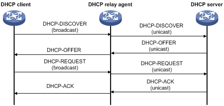
DHCP relay agent support for Option 82
Option 82 records the location information about the DHCP client. It enables the administrator to locate the DHCP client for security and accounting purposes, and to assign IP addresses in a specific range to clients. For more information, see "Relay agent option (Option 82)."
If the DHCP relay agent supports Option 82, it handles DHCP requests by following the strategies described in Table 3.
If a response returned by the DHCP server contains Option 82, the DHCP relay agent removes the Option 82 before forwarding the response to the client.
Table 3 Handling strategies of the DHCP relay agent
|
If a DHCP request has… |
Handling strategy |
The DHCP relay agent… |
|
Option 82 |
Drop |
Drops the message. |
|
Keep |
Forwards the message without changing Option 82. |
|
|
Replace |
Forwards the message after replacing the original Option 82 with the Option 82 padded according to the configured padding format, padding content, and code type. |
|
|
No Option 82 |
N/A |
Forwards the message after adding Option 82 padded according to the configured padding format, padding content, and code type. |
DHCP relay agent configuration task list
|
Tasks at a glance |
|
(Required.) Enabling DHCP |
|
(Required.) Enabling the DHCP relay agent on an interface |
|
(Required.) Specifying DHCP servers on a relay agent |
|
(Optional.) Configuring the DHCP relay agent security features |
|
(Optional.) Configuring the DHCP relay agent to release an IP address |
|
(Optional.) Configuring Option 82 |
|
(Optional.) Setting the DSCP value for DHCP packets sent by the DHCP relay agent |
Enabling DHCP
You must enable DHCP to validate other DHCP relay agent settings.
To enable DHCP:
|
Step |
Command |
Remarks |
|
1. Enter system view. |
system-view |
N/A |
|
2. Enable DHCP. |
dhcp enable |
By default, DHCP is disabled. |
Enabling the DHCP relay agent on an interface
With the DHCP relay agent enabled, an interface forwards incoming DHCP requests to a DHCP server.
An IP address pool that contains the IP address of the DHCP relay agent interface must be configured on the DHCP server. Otherwise, the DHCP clients connected to the relay agent cannot obtain correct IP addresses.
To enable the DHCP relay agent on an interface:
|
Step |
Command |
Remarks |
|
1. Enter system view. |
system-view |
N/A |
|
2. Enter interface view. |
interface interface-type interface-number |
N/A |
|
3. Enable the DHCP relay agent. |
dhcp select relay |
By default, when DHCP is enabled, an interface operates in the DHCP server mode. |
Specifying DHCP servers on a relay agent
To improve availability, you can specify several DHCP servers on the DHCP relay agent. When the interface receives request messages from clients, the relay agent forwards them to all DHCP servers.
Follow these guidelines when you specify a DHCP server address on a relay agent:
· The IP address of any specified DHCP server must not reside on the same subnet as the IP address of the relay agent interface. Otherwise, the clients might fail to obtain IP addresses.
· You can specify a maximum of eight DHCP servers.
To specify a DHCP server address on a relay agent:
|
Command |
Remarks |
|
|
1. Enter system view. |
system-view |
N/A |
|
2. Enter interface view. |
interface interface-type interface-number |
N/A |
|
3. Specify a DHCP server address on the relay agent. |
dhcp relay server-address ip-address |
By default, no DHCP server address is specified on the relay agent. |
Configuring the DHCP relay agent security features
Enabling the DHCP relay agent to record relay entries
Perform this task to enable the DHCP relay agent to automatically record clients' IP-to-MAC bindings (relay entries) after they obtain IP addresses through DHCP.
Some security features, such as ARP address check and IP source guard, use the recorded relay entries to check incoming packets and block packets that do not match any entry. In this way, illegal hosts are not able to access external networks through the relay agent.
To enable the DHCP relay agent to record relay entries:
|
Step |
Command |
Remarks |
|
1. Enter system view. |
system-view |
N/A |
|
2. Enable the relay agent to record relay entries. |
dhcp relay client-information record |
By default, the relay agent does not record relay entries. |
Enabling periodic refresh of dynamic relay entries
A DHCP client unicasts a DHCP-RELEASE message to the DHCP server to release its IP address. The DHCP relay agent simply conveys the message to the DHCP server and does not remove the IP-to-MAC entry of the client.
With this feature, the DHCP relay agent uses the IP address of a relay entry and the MAC address of the DHCP relay interface to periodically send a DHCP-REQUEST message to the DHCP server.
· If the server returns a DHCP-ACK message or does not return any message within a specific interval, the DHCP relay agent removes the relay entry. In addition, upon receiving the DHCP-ACK message, the relay agent sends a DHCP-RELEASE message to release the IP address.
· If the server returns a DHCP-NAK message, the relay agent keeps the relay entry.
To enable periodic refresh of dynamic relay entries:
|
Step |
Command |
Remarks |
|
1. Enter system view. |
system-view |
N/A |
|
2. Enable periodic refresh of dynamic relay entries. |
dhcp relay client-information refresh enable |
By default, periodic refresh of dynamic relay entries is enabled. |
|
3. Configure the refresh interval. |
dhcp relay client-information refresh [ auto | interval interval ] |
By default, the refresh interval is auto, which is calculated based on the number of total relay entries. |
Enabling DHCP starvation attack protection
A DHCP starvation attack occurs when an attacker constantly sends forged DHCP requests using different MAC addresses in the chaddr field to a DHCP server. This exhausts the IP address resources of the DHCP server so legitimate DHCP clients cannot obtain IP addresses. The DHCP server might also fail to work because of exhaustion of system resources. The following methods are available to relieve or prevent such attacks.
· To relieve a DHCP starvation attack that uses DHCP packets encapsulated with different source MAC addresses, you can limit the number of ARP entries that a Layer 3 interface can learn or MAC addresses that a Layer 2 port can learn. You can also configure an interface that has learned the maximum MAC addresses to discard packets whose source MAC addresses are not in the MAC address table.
· To prevent a DHCP starvation attack that uses DHCP requests encapsulated with the same source MAC address, you can enable MAC address check on the DHCP relay agent. The DHCP relay agent compares the chaddr field of a received DHCP request with the source MAC address in the frame header. If they are the same, the DHCP relay agent forwards the request to the DHCP server. If not, the relay agent discards the request.
Enable MAC address check only on the DHCP relay agent directly connected to the DHCP clients. A DHCP relay agent changes the source MAC address of DHCP packets before sending them. If you enable this feature on an intermediate relay agent, it might discard valid DHCP packets, and the sending clients will not obtain IP addresses.
A MAC address check entry has an aging time. When the aging time expires, the entry ages out, and the DHCP relay agent rechecks the validity of DHCP requests sent from the MAC address in the entry.
To enable MAC address check:
|
Step |
Command |
Remarks |
|
1. Enter system view. |
system-view |
N/A |
|
2. Configure the aging time for MAC address check entries. |
dhcp relay check mac-address aging-time time |
The default aging time is 300 seconds. This command takes effect only after you execute the dhcp relay check mac-address command. |
|
3. Enter the interface view. |
interface interface-type interface-number |
N/A |
|
4. Enable MAC address check. |
dhcp relay check mac-address |
By default, MAC address check is disabled. |
Configuring the DHCP relay agent to release an IP address
Configure the relay agent to release the IP address for a relay entry. The relay agent sends a DHCP-RELEASE message to the server and meanwhile deletes the relay entry. Upon receiving the DHCP-RELEASE message, the DHCP server releases the IP address.
To configure the DHCP relay agent to release an IP address:
|
Step |
Command |
Remarks |
|
1. Enter system view. |
system-view |
N/A |
|
2. Configure the DHCP relay agent to release an IP address. |
dhcp relay release ip client-ip [ vpn-instance vpn-instance-name ] |
This command can release only the IP addresses in the recorded relay entries. |
Configuring Option 82
Follow these guidelines when you configure Option 82:
· To support Option 82, you must perform related configuration on both the DHCP server and relay agent. For DHCP server Option 82 configuration, see "Enabling handling of Option 82."
· The system name (sysname) if padded in sub-option 1 (node identifier) of Option 82 must not contain spaces. Otherwise, the DHCP relay agent drops the message.
|
Step |
Command |
Remarks |
|
1. Enter system view. |
system-view |
N/A |
|
2. Enter interface view. |
interface interface-type interface-number |
N/A |
|
3. Enable the relay agent to handle Option 82. |
dhcp relay information enable |
By default, handling of Option 82 is disabled. |
|
4. (Optional.) Configure the strategy for handling DHCP requests that contain Option 82. |
dhcp relay information strategy { drop | keep | replace } |
By default, the handling strategy is replace. |
|
5. (Optional.) Configure the padding content and code type for the Circuit ID sub-option. |
dhcp relay information circuit-id { string circuit-id | { normal | verbose [ node-identifier { mac | sysname | user-defined node-identifier } ] } [ format { ascii | hex } ] } |
By default, the padding format for Circuit ID sub-option is normal, and the code type is hex. |
|
6. (Optional.) Configure the padding content and code type for the Remote ID sub-option. |
dhcp relay information remote-id { normal [ format { ascii | hex } ] | string remote-id | sysname } |
By default, the padding format for the Remote ID sub-option is normal, and the code type is hex. |
Setting the DSCP value for DHCP packets sent by the DHCP relay agent
The DSCP value of a packet specifies the priority level of the packet and affects the transmission priority of the packet.
To set the DSCP value for DHCP packets sent by the DHCP relay agent:
|
Step |
Command |
Remarks |
|
1. Enter system view. |
system-view |
N/A |
|
2. Set the DSCP value for DHCP packets sent by the DHCP relay agent. |
dhcp dscp dscp-value |
By default, the DSCP value in DHCP packets sent by the DHCP relay agent is 56. |
Displaying and maintaining the DHCP relay agent
Execute display commands in any view and reset commands in user view.
|
Task |
Command |
|
Display information about DHCP servers specified on an interface. |
display dhcp relay server-address [ interface interface-type interface-number ] |
|
Display Option 82 configuration information on the DHCP relay agent. |
display dhcp relay information [ interface interface-type interface-number ] |
|
Display relay entries on the DHCP relay agent. |
display dhcp relay client-information [ interface interface-type interface-number | ip ip-address [ vpn-instance vpn-instance-name ] ] |
|
Display packet statistics on the DHCP relay agent. |
display dhcp relay statistics [ interface interface-type interface-number ] |
|
Display MAC address check entries on the DHCP relay agent. |
display dhcp relay check mac-address |
|
Clear relay entries on the DHCP relay agent. |
reset dhcp relay client-information [ interface interface-type interface-number | ip ip-address [ vpn-instance vpn-instance-name ] ] |
|
Clear packet statistics on the DHCP relay agent. |
reset dhcp relay statistics [ interface interface-type interface-number ] |
DHCP relay agent configuration examples
DHCP relay agent configuration example
Network requirements
As shown in Figure 22, configure the DHCP relay agent on Switch A so that DHCP clients can obtain IP addresses and configuration parameters from the DHCP server on another subnet.
The DHCP relay agent and server are on different subnets, so configure static or dynamic routing to make them reachable to each other.
Perform the configuration on the DHCP server to guarantee the client-server communication. For DHCP server configuration information, see "DHCP server configuration examples."
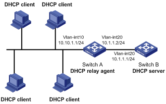
Configuration procedure
# Specify IP addresses for the interfaces. (Details not shown.)
# Enable DHCP.
<SwitchA> system-view
[SwitchA] dhcp enable
# Enable the DHCP relay agent on VLAN-interface 10.
[SwitchA] interface vlan-interface 10
[SwitchA-Vlan-interface10] dhcp select relay
# Specify the IP address of the DHCP server on the relay agent.
[SwitchA-Vlan-interface10] dhcp relay server-address 10.1.1.1
Verifying the configuration
After the preceding configuration is complete, DHCP clients can obtain IP addresses and other network parameters from the DHCP server through the DHCP relay agent. You can use the display dhcp relay statistics command to display the statistics of DHCP packets forwarded by the DHCP relay agent. If you enable relay entry record on the DHCP relay agent with the dhcp relay client-information record command, you can use the display dhcp relay client-information command to display relay entries.
Option 82 configuration example
Network requirements
As shown in Figure 22, the DHCP relay agent (Switch A) replaces Option 82 in DHCP requests before forwarding them to the DHCP server (Switch B).
· The Circuit ID sub-option is company001.
· The Remote ID sub-option is device001.
To use Option 82, you must also enable the DHCP server to handle Option 82.
Configuration procedure
# Specify IP addresses for the interfaces. (Details not shown.)
# Enable DHCP.
<SwitchA> system-view
[SwitchA] dhcp enable
# Enable the DHCP relay agent on VLAN-interface 10.
[SwitchA] interface vlan-interface 10
[SwitchA-Vlan-interface10] dhcp select relay
# Specify the IP address of the DHCP server.
[SwitchA-Vlan-interface10] dhcp relay server-address 10.1.1.1
# Configure the handling strategies and padding content of Option 82.
[SwitchA-Vlan-interface10] dhcp relay information enable
[SwitchA-Vlan-interface10] dhcp relay information strategy replace
[SwitchA-Vlan-interface10] dhcp relay information circuit-id string company001
[SwitchA-Vlan-interface10] dhcp relay information remote-id string device001
Troubleshooting DHCP relay agent configuration
Symptom
DHCP clients cannot obtain configuration parameters through the DHCP relay agent.
Analysis
Some problems might occur with the DHCP relay agent or server configuration.
Solution
To locate the problem, enable debugging and execute the display command on the DHCP relay agent to view the debugging information and interface state information.
Check that:
· DHCP is enabled on the DHCP server and relay agent.
· The DHCP server has an address pool on the same subnet as the DHCP clients.
· The DHCP server and DHCP relay agent can reach each other.
· The DHCP server address specified on the DHCP relay agent interface connected to the DHCP clients is correct.
Configuring the DHCP client
With DHCP client enabled, an interface uses DHCP to obtain configuration parameters from the DHCP server, for example, an IP address.
The DHCP client configuration is supported only on Layer 3 Ethernet interfaces (including management Ethernet interfaces and subinterfaces), VLAN interfaces, and Layer 3 aggregate interfaces.
When multiple VLAN interfaces with the same MAC address use DHCP for IP address acquisition through a relay agent, the DHCP server cannot be a Windows Server 2000 or Windows Server 2003.
Enabling the DHCP client on an interface
Follow these guidelines when you enable the DHCP client on an interface:
· If the number of IP address request failures reaches the system-defined amount, the DHCP client-enabled interface uses a default IP address.
· An interface can be configured to acquire an IP address in multiple ways. The new configuration overwrites the old.
· Secondary IP addresses cannot be configured on an interface that is enabled with the DHCP client.
· If the interface obtains an IP address on the same segment as another interface on the device, the interface does not use the assigned address. Instead, it requests a new IP address from the DHCP server.
To enable the DHCP client on an interface:
|
Step |
Command |
Remarks |
|
1. Enter system view. |
system-view |
N/A |
|
2. Enter interface view. |
interface interface-type interface-number |
N/A |
|
3. Configure an interface to use DHCP for IP address acquisition. |
ip address dhcp-alloc |
By default, an interface does not use DHCP for IP address acquisition. |
Configuring a DHCP client ID for an interface
A DHCP client ID is added to the DHCP option 61. A DHCP server can specify IP addresses for clients based on the DHCP client ID.
Make sure the IDs for different DHCP clients are unique.
To configure a DHCP client ID for an interface:
|
Step |
Command |
Remarks |
|
1. Enter system view. |
system-view |
N/A |
|
2. Enter interface view. |
interface interface-type interface-number |
N/A |
|
3. Configure a DHCP client ID for the interface. |
dhcp client identifier { ascii string | hex string | mac interface-type interface-number } |
By default, an interface generates the DHCP client ID based on its MAC address. If the interface has no MAC address, it uses the MAC address of the first Ethernet interface to generate its client ID. |
|
4. Verify the client ID configuration. |
display dhcp client [ verbose ] [ interface interface-type interface-number ] |
DHCP client ID includes ID type and type value. Each ID type has a fixed type value. You can check the fields for the client ID to verify which type of client ID is used: · If an ASCII string is used as the client ID, the type value is 00. · If a hex string is used as the client ID, the type value is the first two characters in the string. · If the MAC address of a specific interface is used as the client ID, the type value is 01. |
Enabling duplicated address detection
DHCP client detects IP address conflict through ARP packets. An attacker can act as the IP address owner to send an ARP reply, making the client unable to use the IP address assigned by the server. As a best practice, disable duplicate address detection when ARP attacks exist on the network.
To enable duplicated address detection:
|
Step |
Command |
Remarks |
|
1. Enter system view. |
system-view |
N/A |
|
2. Enable duplicate address detection. |
dhcp client dad enable |
By default, the duplicate address detection feature is enabled on an interface. |
Setting the DSCP value for DHCP packets sent by the DHCP client
The DSCP value of a packet specifies the priority level of the packet and affects the transmission priority of the packet.
To set the DSCP value for DHCP packets sent by the DHCP client:
|
Step |
Command |
Remarks |
|
1. Enter system view. |
system-view |
N/A |
|
2. Set the DSCP value for DHCP packets sent by the DHCP client. |
dhcp dscp dscp-value |
By default, the DSCP value in DHCP packets sent by the DHCP client is 56. |
Displaying and maintaining the DHCP client
Execute display command in any view.
|
Task |
Command |
|
Display DHCP client information. |
display dhcp client [ verbose ] [ interface interface-type interface-number ] |
DHCP client configuration example
Network requirements
As shown in Figure 24, on a LAN, Switch B contacts the DHCP server through VLAN-interface 2 to obtain an IP address, DNS server address, and static route information. The DHCP client IP address resides on network 10.1.1.0/24. The DNS server address is 20.1.1.1. The next hop of the static route to network 20.1.1.0/24 is 10.1.1.2.
The DHCP server uses Option 121 to assign static route information to DHCP clients. Figure 23 shows the Option 121 format. The destination descriptor field contains the following parts: subnet mask length and destination network address, both in hexadecimal notation. In this example, the destination descriptor is 18 14 01 01 (the subnet mask length is 24 and the network address is 20.1.1.0 in dotted decimal notation). The next hop address is 0A 01 01 02 (10.1.1.2 in dotted decimal notation).
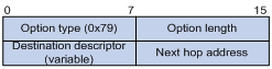
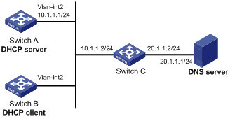
Configuration procedure
1. Configure Switch A:
# Specify the IP address of VLAN-interface 2.
<SwitchA> system-view
[SwitchA] interface vlan-interface 2
[SwitchA-Vlan-interface2] ip address 10.1.1.1 24
[SwitchA-Vlan-interface2] quit
# Enable the DHCP service.
[SwitchA] dhcp enable
# Exclude an IP address from dynamic allocation.
[SwitchA] dhcp server forbidden-ip 10.1.1.2
# Configure DHCP address pool 0 and specify the subnet, lease duration, DNS server address, and a static route to subnet 20.1.1.0/24.
[SwitchA] dhcp server ip-pool 0
[SwitchA-dhcp-pool-0] network 10.1.1.0 mask 255.255.255.0
[SwitchA-dhcp-pool-0] expired day 10
[SwitchA-dhcp-pool-0] dns-list 20.1.1.1
[SwitchA-dhcp-pool-0] option 121 hex 18 14 01 01 0A 01 01 02
2. Configure Switch B:
# Configure VLAN-interface 2 to use DHCP for IP address acquisition.
<SwitchB> system-view
[SwitchB] interface vlan-interface 2
[SwitchB-Vlan-interface2] ip address dhcp-alloc
[SwitchB-Vlan-interface2] quit
Verifying the configuration
# Use the display dhcp client command to display the IP address and other network parameters assigned to Switch B.
[SwitchB-Vlan-interface2] display dhcp client verbose
Vlan-interface2 DHCP client information:
Current state: BOUND
Allocated IP: 10.1.1.3 255.255.255.0
Allocated lease: 864000 seconds, T1: 331858 seconds, T2: 756000 seconds
Lease from May 21 19:00:29 2012 to May 31 19:00:29 2012
DHCP server: 10.1.1.1
Transaction ID: 0xcde72232
Classless static routes:
Destination: 20.1.1.0, Mask: 255.255.255.0, NextHop: 10.1.1.2
DNS servers: 20.1.1.1
Client ID type: acsii(type value=00)
Client ID value: 000c.29d3.8659-Vlan2
Client ID (with type) hex: 0030-3030-632e-3239-
6433-2e38-3635-392d-
4574-6830-2f30-2f32
T1 will timeout in 3 days 19 hours 48 minutes 43 seconds
# Use the display ip routing-table command to display the route information on Switch B. The output shows that a static route to network 20.1.1.0/24 is added to the routing table.
[SwitchB] display ip routing-table
Destinations : 11 Routes : 11
Destination/Mask Proto Pre Cost NextHop Interface
10.1.1.0/24 Direct 0 0 10.1.1.3 Vlan2
10.1.1.3/32 Direct 0 0 127.0.0.1 InLoop0
20.1.1.0/24 Static 70 0 10.1.1.2 Vlan2
10.1.1.255/32 Direct 0 0 10.1.1.3 Vlan2
127.0.0.0/8 Direct 0 0 127.0.0.1 InLoop0
127.0.0.0/32 Direct 0 0 127.0.0.1 InLoop0
127.0.0.1/32 Direct 0 0 127.0.0.1 InLoop0
127.255.255.255/32 Direct 0 0 127.0.0.1 InLoop0
224.0.0.0/4 Direct 0 0 0.0.0.0 NULL0
224.0.0.0/24 Direct 0 0 0.0.0.0 NULL0
255.255.255.255/32 Direct 0 0 127.0.0.1 InLoop0
Configuring DHCP snooping
DHCP snooping works between the DHCP client and server, or between the DHCP client and DHCP relay agent. It guarantees that DHCP clients obtain IP addresses from authorized DHCP servers. Also, it records IP-to-MAC bindings of DHCP clients (called DHCP snooping entries) for security purposes.
DHCP snooping does not work between the DHCP server and DHCP relay agent.
Overview
DHCP snooping defines trusted and untrusted ports to make sure clients obtain IP addresses only from authorized DHCP servers.
· Trusted—A trusted port can forward DHCP messages correctly to make sure the clients get IP addresses from authorized DHCP servers.
· Untrusted—An untrusted port discards received DHCP-ACK and DHCP-OFFER messages to prevent unauthorized servers from assigning IP addresses.
DHCP snooping reads DHCP-ACK messages received from trusted ports and DHCP-REQUEST messages to create DHCP snooping entries. A DHCP snooping entry includes the MAC and IP addresses of a client, the port that connects to the DHCP client, and the VLAN.
The following features need to use DHCP snooping entries:
· ARP detection—Uses DHCP snooping entries to filter ARP packets from unauthorized clients. For more information, see Security Configuration Guide.
· IP source guard—Uses DHCP snooping entries to filter illegal packets on a per-port basis. For more information, see Security Configuration Guide.
Application of trusted and untrusted ports
Configure ports facing the DHCP server as trusted ports, and configure other ports as untrusted ports.
As shown in Figure 25, configure the DHCP snooping device's port that is connected to the DHCP server as a trusted port. The trusted port forwards response messages from the DHCP server to the client. The untrusted port connected to the unauthorized DHCP server discards incoming DHCP response messages.
Figure 25 Trusted and untrusted ports
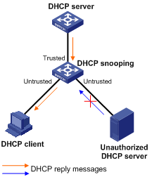
In a cascaded network as shown in Figure 26, configure each DHCP snooping device's ports connected to other DHCP snooping devices as trusted ports. To save system resources, you can disable the untrusted ports that are not directly connected to DHCP clients from generating DHCP snooping entries.
Figure 26 Trusted and untrusted ports in a cascaded network
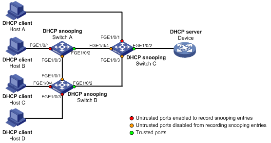
DHCP snooping support for Option 82
Option 82 records the location information about the DHCP client so the administrator can locate the DHCP client for security and accounting purposes. For more information about Option 82, see "Relay agent option (Option 82)."
DHCP snooping uses the same strategies as the DHCP relay agent to handle Option 82 for DHCP request messages, as shown in Table 4. If a response returned by the DHCP server contains Option 82, DHCP snooping removes Option 82 before forwarding the response to the client. If the response contains no Option 82, DHCP snooping forwards it directly.
|
If a DHCP request has… |
Handling strategy |
DHCP snooping… |
|
Option 82 |
Drop |
Drops the message. |
|
Keep |
Forwards the message without changing Option 82. |
|
|
Replace |
Forwards the message after replacing the original Option 82 with the Option 82 padded according to the configured padding format, padding content, and code type. |
|
|
No Option 82 |
N/A |
Forwards the message after adding the Option 82 padded according to the configured padding format, padding content, and code type. |
DHCP snooping configuration task list
If you configure DHCP snooping settings on a Layer 2 Ethernet interface that has been added to an aggregation group, the settings do not take effect unless the interface is removed from the aggregation group.
|
Tasks at a glance |
|
(Required.) Configuring basic DHCP snooping |
|
(Optional.) Configuring Option 82 |
|
(Optional.) Configuring DHCP snooping entry auto backup |
|
(Optional.) Enabling DHCP starvation attack protection |
|
(Optional.) Enabling DHCP-REQUEST attack protection |
|
(Optional.) Setting the maximum number of DHCP snooping entries |
|
(Optional.) Configuring DHCP packet rate limit |
Configuring basic DHCP snooping
Follow these guidelines when you configure basic DHCP snooping:
· Specify the ports connected to authorized DHCP servers as trusted ports to make sure that DHCP clients can obtain valid IP addresses. The trusted ports and the ports connected to DHCP clients must be in the same VLAN.
· Layer 2 Ethernet interfaces and Layer 2 aggregate interfaces can be specified as trusted ports. For more information about aggregate interfaces, see Layer 2—LAN Switching Configuration Guide.
· If you configure DHCP snooping settings on a Layer 2 Ethernet interface that has been added to an aggregation group, the settings do not take effect unless the interface is removed from the aggregation group.
To configure basic DHCP snooping:
|
Step |
Command |
Remarks |
|
1. Enter system view. |
system-view |
N/A |
|
2. Enable DHCP snooping. |
dhcp snooping enable |
By default, DHCP snooping is disabled. |
|
3. Enter interface view of a layer 2 Ethernet interface or a layer 2 aggregate interface. |
interface interface-type interface-number |
This interface must connect to the DHCP server. |
|
4. Specify the port as a trusted port. |
dhcp snooping trust |
By default, all ports are untrusted ports after DHCP snooping is enabled. |
|
5. Return to system view. |
quit |
N/A |
|
6. Enter interface view of a layer 2 Ethernet interface or a layer 2 aggregate interface. |
interface interface-type interface-number |
This interface must connect to the DHCP client. |
|
7. (Optional.) Enable recording of DHCP snooping entries. |
By default, after DHCP snooping is enabled, recording of DHCP snooping entries is disabled. |
Configuring Option 82
Follow these guidelines when you configure Option 82:
· If you configure Option 82 on a Layer 2 Ethernet interface that has been added to an aggregation group, the settings do not take effect unless the interface is removed from the aggregation group.
· To support Option 82, you must configure Option 82 on both the DHCP server and the DHCP snooping device. For information about configuring Option 82 on the DHCP server, see "Enabling handling of Option 82."
· If the handling strategy is configured as replace, you must configure a padding format for Option 82. If the handling strategy is keep or drop, there is no need to configure any padding format.
· If Option 82 contains the device name, the device name must include no spaces. Otherwise, DHCP snooping drops the message. You can use the sysname command to specify the device name. For more information about this command, see Fundamentals Command Reference.
To configure DHCP snooping to support Option 82:
|
Step |
Command |
Remarks |
|
1. Enter system view. |
system-view |
N/A |
|
2. Enter interface view of a layer 2 Ethernet interface or a layer 2 aggregate interface. |
interface interface-type interface-number |
N/A |
|
3. Enable DHCP snooping to support Option 82. |
dhcp snooping information enable |
By default, DHCP snooping does not support Option 82. |
|
4. (Optional.) Configure a handling strategy for DHCP requests that contain Option 82. |
dhcp snooping information strategy { drop | keep | replace } |
By default, the handling strategy is replace. |
|
5. (Optional.) Configure the padding content and code type for the Circuit ID sub-option. |
dhcp snooping information circuit-id { [ vlan vlan-id ] string circuit-id | { normal | verbose [ node-identifier { mac | sysname | user-defined node-identifier } ] } [ format { ascii | hex } ] } |
By default, the padding format is normal and the code type is hex for the Circuit ID sub-option. |
|
6. (Optional.) Configure the padding content and code type for the Remote ID sub-option. |
dhcp snooping information remote-id { normal [ format { ascii | hex } ] | [ vlan vlan-id ] string remote-id | sysname } |
By default, the padding format is normal and the code type is hex for the Remote ID sub-option. |
Configuring DHCP snooping entry auto backup
DHCP snooping entries cannot survive a reboot. If the DHCP snooping device is rebooted, security features (such as IP source guard) that use DHCP snooping entries to authenticate users reject requests from clients until new entries are learned.
To avoid this problem, you can back up DHCP snooping entries to a file so that DHCP snooping can read DHCP snooping entries from this file during a reboot.
|
|
NOTE: If you disable DHCP snooping with the undo dhcp snooping enable command, the device deletes all DHCP snooping entries, including those stored in the specified file. |
To save DHCP snooping entries:
|
Step |
Command |
Remarks |
|
1. Enter system view. |
system-view |
N/A |
|
2. Specify a file to save DHCP snooping entries. |
dhcp snooping binding database filename { filename | url url [ username username [ password { cipher | simple } key ] ] } |
By default, no file is specified. This command enables the device to immediately save DHCP snooping entries to the specified database file. If the file does not exist, the device automatically creates the file. The device does not update the file for a specified amount of time after a DHCP snooping entry changes. The default period is 300 seconds. To change the value, use the dhcp snooping binding database update interval command. |
|
3. (Optional.) Manually save DHCP snooping entries to the file. |
dhcp snooping binding database update now |
DHCP snooping entries are saved to the database file each time this command is executed. |
|
4. (Optional.) Set the amount of time to wait after a DHCP snooping entry changes before updating the database file. |
dhcp snooping binding database update interval seconds |
The default setting is 300 seconds. When a DHCP snooping entry is learned or removed, the device does not update the database file until after the specified waiting period. All changed entries during that period will be updated. |
Enabling DHCP starvation attack protection
A DHCP starvation attack occurs when an attacker constantly sends forged DHCP requests that contain identical or different sender MAC addresses in the chaddr field to a DHCP server. This attack exhausts the IP address resources of the DHCP server so legitimate DHCP clients cannot obtain IP addresses. The DHCP server might also fail to work because of exhaustion of system resources. For information about the fields of DHCP packet, see "DHCP message format."
Protect against starvation attacks in the following ways:
· To relieve a DHCP starvation attack that uses DHCP requests encapsulated with different sender MAC addresses, you can limit the number of MAC addresses that a Layer 2 port can learn by using the mac-address max-mac-count command. For more information about the command, see Layer 2—LAN Switching Command Reference.
· To prevent a DHCP starvation attack that uses DHCP requests encapsulated with the same sender MAC address, perform this task to enable MAC address check for DHCP snooping. This feature compares the chaddr field of a received DHCP request with the source MAC address field in the frame header. If they are the same, the request is considered valid and forwarded to the DHCP server. If not, the request is discarded.
To enable MAC address check:
|
Step |
Command |
Remarks |
|
1. Enter system view. |
system-view |
N/A |
|
2. Enter interface view of a layer 2 Ethernet interface or a layer 2 aggregate interface. |
interface interface-type interface-number |
N/A |
|
3. Enable MAC address check. |
dhcp snooping check mac-address |
By default, MAC address check is disabled. |
Enabling DHCP-REQUEST attack protection
DHCP-REQUEST messages include DHCP lease renewal packets, DHCP-DECLINE packets, and DHCP-RELEASE packets. This feature prevents the unauthorized clients that forge the DHCP-REQUEST messages from attacking the DHCP server.
Attackers can forge DHCP lease renewal packets to renew leases for legitimate DHCP clients that no longer need the IP addresses. These forged messages disable the victim DHCP server from releasing the IP addresses.
Attackers can also forge DHCP-DECLINE or DHCP-RELEASE packets to terminate leases for legitimate DHCP clients that still need the IP addresses.
To prevent such attacks, you can enable DHCP-REQUEST check. This feature uses DHCP snooping entries to check incoming DHCP-REQUEST messages. If a matching entry is found for a message, this feature compares the entry with the message information. If they are consistent, the message is considered as valid and forwarded to the DHCP server. If they are different, the message is considered as a forged message and is discarded. If no matching entry is found, the message is considered valid and forwarded to the DHCP server.
To enable DHCP-REQUEST check:
|
Step |
Command |
Remarks |
|
1. Enter system view. |
system-view |
N/A |
|
2. Enter interface view of a layer 2 Ethernet interface or a layer 2 aggregate interface. |
interface interface-type interface-number |
N/A |
|
3. Enable DHCP-REQUEST check. |
dhcp snooping check request-message |
By default, DHCP-REQUEST check is disabled. You can enable DHCP-REQUEST check only on Layer 2 Ethernet interfaces and Layer 2 aggregate interfaces. |
Setting the maximum number of DHCP snooping entries
Perform this task to prevent the system resources from being overused.
To set the maximum number of DHCP snooping entries:
|
Step |
Command |
Remarks |
|
1. Enter system view. |
system-view |
N/A |
|
2. Enter interface view of a layer 2 Ethernet interface or a layer 2 aggregate interface. |
interface interface-type interface-number |
N/A |
|
3. Set the maximum number of DHCP snooping entries that the interface can learn. |
dhcp snooping max-learning-num number |
By default, the number of DHCP snooping entries for an interface to learn is not limited. |
Configuring DHCP packet rate limit
Perform this task to configure the maximum rate at which an interface can receive DHCP packets. This feature discards exceeding DHCP packets to prevent attacks that send large numbers of DHCP packets.
To configure DHCP packet rate limit:
|
Step |
Command |
Remarks |
|
1. Enter system view. |
system-view |
N/A |
|
2. Enter interface view of a layer 2 Ethernet interface or a layer 2 aggregate interface. |
interface interface-type interface-number |
N/A |
|
3. Configure the maximum rate at which the interface can receive DHCP packets. |
dhcp snooping rate-limit rate |
By default, incoming DHCP packets are not rate limited. You can configure this command only on Layer 2 Ethernet interfaces and Layer 2 aggregate interfaces. If you configure the rate on a Layer 2 Ethernet interface that is a member port of a Layer 2 aggregate interface, the Layer 2 Ethernet interface uses the DHCP packet maximum rate configured on the Layer 2 aggregate interface. If the Layer 2 Ethernet interface leaves the aggregation group, it uses its own DHCP packet maximum rate. |
Displaying and maintaining DHCP snooping
Execute display commands in any view, and reset commands in user view.
|
Task |
Command |
Remarks |
|
Display DHCP snooping entries. |
display dhcp snooping binding [ ip ip-address [ vlan vlan-id ] ] |
Available in any view. |
|
Display Option 82 configuration information on the DHCP snooping device. |
display dhcp snooping information { all | interface interface-type interface-number } |
Available in any view. |
|
Display DHCP packet statistics on the DHCP snooping device (in standalone mode). |
display dhcp snooping packet statistics [ slot slot-number ] |
Available in any view. |
|
Display DHCP packet statistics on the DHCP snooping device (in IRF mode). |
display dhcp snooping packet statistics [ chassis chassis-number slot slot-number ] |
Available in any view. |
|
Display information about trusted ports. |
display dhcp snooping trust |
Available in any view. |
|
Display information about the file that stores DHCP snooping entries. |
display dhcp snooping binding database |
Available in any view. |
|
Clear DHCP snooping entries. |
reset dhcp snooping binding { all | ip ip-address [ vlan vlan-id ] } |
Available in user view. |
|
Clear DHCP packet statistics on the DHCP snooping device (distributed devices–centralized IRF devices–in standalone mode). |
reset dhcp snooping packet statistics [ slot slot-number ] |
Available in user view. |
|
Clear DHCP packet statistics on the DHCP snooping device (distributed devices–in IRF mode). |
reset dhcp snooping packet statistics [ chassis chassis-number slot slot-number ] |
Available in user view. |
DHCP snooping configuration examples
Basic DHCP snooping configuration example
Network requirements
As shown in Figure 27, configure the port FortyGigE 1/0/1 connected to the DHCP server as a trusted port and configure other ports as untrusted ports. Enable DHCP snooping to record clients' IP-MAC bindings by reading DHCP-ACK messages received from the trusted port and DHCP-REQUEST messages.

Configuration procedure
# Enable DHCP snooping.
<SwitchB> system-view
[SwitchB] dhcp snooping enable
# Configure FortyGigE 1/0/1 as a trusted port.
[SwitchB] interface FortyGigE 1/0/1
[SwitchB-FortyGigE1/0/1] dhcp snooping trust
[SwitchB-FortyGigE1/0/1] quit
# Enable DHCP snooping to record clients' IP-MAC bindings on FortyGigE 1/0/2.
[SwitchB] interface FortyGigE 1/0/2
[SwitchB-FortyGigE1/0/2] dhcp snooping binding record
[SwitchB-FortyGigE1/0/2] quit
Verifying the configuration
The DHCP client can obtain an IP address and other configuration parameters only from the authorized DHCP server. You can display the DHCP snooping entry recorded for the client with the display dhcp snooping binding command.
Option 82 configuration example
Network requirements
As shown in Figure 28, enable DHCP snooping and configure Option 82 on Switch B as follows:
· Configure the handling strategy for DHCP requests that contain Option 82 as replace.
· On FortyGigE1/0/2, configure the padding content for the Circuit ID sub-option as company001 and for the Remote ID sub-option as device001.
· On FortyGigE1/0/3, for the Circuit ID sub-option, configure the padding format as verbose, access node identifier as sysname, and code type as ascii. For the Remote ID sub-option, configure the padding content as device001.
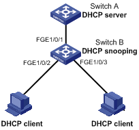
Configuration procedure
# Enable DHCP snooping.
<SwitchB> system-view
[SwitchB] dhcp snooping enable
# Configure FortyGigE 1/0/1 as a trusted port.
[SwitchB] interface FortyGigE1/0/1
[SwitchB-FortyGigE1/0/1] dhcp snooping trust
[SwitchB-FortyGigE1/0/1] quit
# Configure Option 82 on FortyGigE 1/0/2.
[SwitchB] interface FortyGigE1/0/2
[SwitchB-FortyGigE1/0/2] dhcp snooping information enable
[SwitchB-FortyGigE1/0/2] dhcp snooping information strategy replace
[SwitchB-FortyGigE1/0/2] dhcp snooping information circuit-id string company001
[SwitchB-FortyGigE1/0/2] dhcp snooping information remote-id string device001
# Configure Option 82 on FortyGigE 1/0/3.
[SwitchB] interface FortyGigE 1/0/3
[SwitchB-FortyGigE1/0/3] dhcp snooping information enable
[SwitchB-FortyGigE1/0/3] dhcp snooping information strategy replace
[SwitchB-FortyGigE1/0/3] dhcp snooping information circuit-id verbose node-identifier sysname format ascii
[SwitchB-FortyGigE1/0/3] dhcp snooping information remote-id string device001
Verifying the configuration
Use the display dhcp snooping information command to display Option 82 configuration information on FortyGigE 1/0/2 and FortyGigE 1/0/3 on the DHCP snooping device.
Configuring DNS
Overview
Domain Name System (DNS) is a distributed database used by TCP/IP applications to translate domain names into IP addresses. With DNS, you can use easy-to-remember domain names in some applications and let the DNS server translate them into correct IP addresses. The domain name-to-IP address mapping is called a DNS entry.
DNS services can be static or dynamic. After a user specifies a name, the device checks the static name resolution table for an IP address. If no IP address is available, it contacts the DNS server for dynamic name resolution, which takes more time than static name resolution. To improve efficiency, you can put frequently queried name-to-IP address mappings in the local static name resolution table.
Static domain name resolution
Static domain name resolution means manually creating mappings between domain names and IP addresses. For example, you can create a static DNS mapping for a device so that you can Telnet to the device by using the domain name.
Dynamic domain name resolution
Resolution process
1. A user program sends a name query to the resolver of the DNS client.
2. The DNS resolver looks up the local domain name cache for a match. If the resolver finds a match, it sends the corresponding IP address back. If not, it sends a query to the DNS server.
3. The DNS server looks up the corresponding IP address of the domain name in its DNS database. If no match is found, the server sends a query to other DNS servers. This process continues until a result, whether successful or not, is returned.
4. After receiving a response from the DNS server, the DNS client returns the resolution result to the user program.
Figure 29 Dynamic domain name resolution
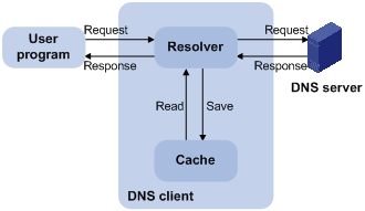
Figure 29 shows the relationship between the user program, DNS client, and DNS server.
The DNS client is made up of the resolver and cache. The user program and DNS client can run on the same device or different devices, but the DNS server and the DNS client usually run on different devices.
Dynamic domain name resolution allows the DNS client to store latest DNS entries in the dynamic domain name cache. The DNS client does not need to send a request to the DNS server for a repeated query within the aging time. To make sure the entries from the DNS server are up to date, a DNS entry is removed when its aging timer expires. The DNS server determines how long a mapping is valid, and the DNS client obtains the aging information from DNS responses.
DNS suffixes
You can configure a domain name suffix list so that the resolver can use the list to supply the missing part of an incomplete name.
For example, you can configure com as the suffix for aabbcc.com. The user only needs to enter aabbcc to obtain the IP address of aabbcc.com because the resolver adds the suffix and delimiter before passing the name to the DNS server.
The name resolver handles the queries based on the domain names that the user enters:
· If the user enters a domain name without a dot (.) (for example, aabbcc), the resolver considers the domain name to be a host name and adds a DNS suffix before performing the query operation. If no match is found for the domain names with any configured suffix, the resolver uses the user entered domain name (for example, aabbcc) to query the IP address.
· If the user enters a domain name with a dot (.) among the letters (for example, www.aabbcc), the resolver directly uses this domain name for the query operation. If the query fails, the resolver adds a DNS suffix for another query operation.
· If the user enters a domain name with a dot (.) at the end (for example, aabbcc.com.), the resolver considers the domain name an FQDN and returns the successful or failed query result. The dot at the end of the domain name is considered a terminating symbol.
The device supports static and dynamic DNS client services.
If an alias is configured for a domain name on the DNS server, the device can resolve the alias into the IP address of the host.
DNS configuration task list
|
Tasks at a glance |
|
(Required.) Configuring the IPv4 DNS client |
|
(Optional.) Specifying the source interface for DNS packets |
|
(Optional.) Configuring the DNS trusted interface |
|
(Optional.) Setting the DSCP value for outgoing DNS packets |
Configuring the IPv4 DNS client
Configuring static domain name resolution
Static domain name resolution allows applications such as Telnet to contact hosts by using host names instead of IPv4 addresses.
Follow these guidelines when you configure static domain name resolution:
· On the public network or a VPN, each host name maps to only one IPv4 address. The most recent configuration for a host name takes effect.
· You can configure the following:
? IPv4 DNS entries for the public network and up to 1024 VPNs.
? A maximum of 1024 IPv4 DNS entries for the public network or each VPN.
To configure static domain name resolution:
|
Step |
Command |
Remarks |
|
1. Enter system view. |
system-view |
N/A |
|
2. Configure a mapping between a host name and an IPv4 address. |
ip host host-name ip-address [ vpn-instance vpn-instance-name ] |
By default, no mapping between a host name and an IPv4 address is configured. |
Configuring dynamic domain name resolution
To use dynamic domain name resolution, configure DNS servers so that DNS queries can be sent to a correct server for resolution. A DNS server manually configured takes precedence over the one dynamically obtained through DHCP, and a DNS server configured earlier takes precedence. A name query is first sent to the DNS server that has the highest priority. If no reply is received, it is sent to the DNS server that has the second highest priority, and thus in turn.
In addition, you can configure a DNS suffix that the system automatically adds to the provided domain name for resolution. A DNS suffix manually configured takes precedence over the one dynamically obtained through DHCP, and a DNS suffix configured earlier takes precedence. The DNS resolver first uses the suffix that has the highest priority. If the name resolution fails, the DNS resolver uses the suffix that has the second highest priority, and thus in turn.
Configuration guidelines
Follow these guidelines when you configure dynamic domain name resolution:
· You can specify DNS server IPv4 addresses as follows:
? Specify DNS server IPv4 addresses for the public network and up to 1024 VPNs.
? Specify a maximum of six DNS server IPv4 addresses for the public network or each VPN.
· You can specify DNS suffixes as follows:
? Specify DNS suffixes for the public network and up to 1024 VPNs.
? Specify a maximum of 16 DNS suffixes for the public network or each VPN.
· An IPv4 name query is first sent to the DNS server IPv4 addresses.
Configuration procedure
To configure dynamic domain name resolution:
|
Command |
Remarks |
|
|
1. Enter system view. |
system-view |
N/A |
|
2. Specify a DNS server IPv4 address. |
dns server ip-address [ vpn-instance vpn-instance-name ] |
By default, no DNS server IPv4 address is specified. |
|
3. (Optional.) Configure a DNS suffix. |
dns domain domain-name [ vpn-instance vpn-instance-name ] |
By default, no DNS suffix is configured and only the provided domain name is resolved. |
Specifying the source interface for DNS packets
By default, the device uses the primary IP address of the output interface of the matching route as the source IP address of a DNS request. Therefore, the source IP address of the DNS packets might vary with DNS servers. In some scenarios, the DNS server only responds to DNS requests sourced from a specific IP address. In such cases, you must specify the source interface for the DNS packets so that the device can always use the primary IP address of the specified source interface as the source IP address of DNS packets.
When sending IPv4 DNS request, the device uses the primary IPv4 address of the source interface as the source IP address of the DNS request.
You can configure only one source interface on the public network or a VPN. You can configure the source interface for the public network and a maximum of 1024 VPNs.
To specify the source interface for DNS packets:
|
Step |
Command |
Remarks |
|
1. Enter system view. |
system-view |
N/A |
|
2. Specify the source interface for DNS packets. |
dns source-interface interface-type interface-number [ vpn-instance vpn-instance-name ] |
By default, no source interface for DNS packets is specified. If you execute the command multiple times, the most recent configuration takes effect. If you specify the vpn-instance vpn-instance-name option, make sure the source interface is on the specified VPN. |
Configuring the DNS trusted interface
By default, an interface obtains DNS suffix and domain name server information from DHCP. The network attacker might act as the DHCP server to assign wrong DNS suffix and domain name server address to the device. As a result, the device fails to get the resolved IP address or might get the wrong IP address. With the DNS trusted interface specified, the device only uses the DNS suffix and domain name server information obtained through the trusted interface to avoid attack.
To configure the DNS trusted interface:
|
Step |
Command |
Remarks |
|
1. Enter system view. |
system-view |
N/A |
|
2. Specify the DNS trusted interface. |
dns trust-interface interface-type interface-number |
By default, no DNS trusted interface is specified. You can configure up to 128 DNS trusted interfaces. |
Setting the DSCP value for outgoing DNS packets
The DSCP value of a packet specifies the priority level of the packet and affects the transmission priority of the packet. A bigger DSCP value represents a higher priority.
To specify the DSCP value for outgoing DNS packets:
|
Step |
Command |
Remarks |
|
1. Enter system view. |
system-view |
N/A |
|
2. Specify the DSCP value for outgoing DNS packets. |
dns dscp dscp-value |
By default, the DSCP value for outgoing DNS packets is 0. |
Displaying and maintaining IPv4 DNS
Execute display commands in any view and reset commands in user view.
|
Task |
Command |
|
Display the domain name resolution table. |
display dns host [ ip ] [ vpn-instance vpn-instance-name ] |
|
Display IPv4 DNS server information. |
display dns server [ dynamic ] [ vpn-instance vpn-instance-name ] |
|
Display DNS suffixes. |
display dns domain [ dynamic ] [ vpn-instance vpn-instance-name ] |
|
Clear information about the dynamic domain name cache. |
reset dns host [ ip ] [ vpn-instance vpn-instance-name ] |
IPv4 DNS configuration examples
Static domain name resolution configuration example
Network requirements
As shown in Figure 30, the device wants to access the host by using an easy-to-remember domain name rather than an IP address.
Configure static domain name resolution on the device so that the device can use the domain name host.com to access the host whose IP address is 10.1.1.2.
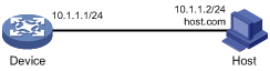
Configuration procedure
# Configure a mapping between host name host.com and IP address 10.1.1.2.
<Sysname> system-view
[Sysname] ip host host.com 10.1.1.2
# Use the ping host.com command to verify that the device can use static domain name resolution to resolve domain name host.com into IP address 10.1.1.2.
[Sysname] ping host.com
Ping host.com (10.1.1.2): 56 data bytes, press CTRL_C to break
56 bytes from 10.1.1.2: icmp_seq=0 ttl=255 time=1.000 ms
56 bytes from 10.1.1.2: icmp_seq=1 ttl=255 time=1.000 ms
56 bytes from 10.1.1.2: icmp_seq=2 ttl=255 time=1.000 ms
56 bytes from 10.1.1.2: icmp_seq=3 ttl=255 time=1.000 ms
56 bytes from 10.1.1.2: icmp_seq=4 ttl=255 time=2.000 ms
--- Ping statistics for host.com ---
5 packet(s) transmitted, 5 packet(s) received, 0.0% packet loss
round-trip min/avg/max/std-dev = 1.000/1.200/2.000/0.400 ms
Dynamic domain name resolution configuration example
Network requirements
As shown in Figure 31, the device wants to access the host by using an easy-to-remember domain name rather than an IP address, and to request the DNS server on the network for an IP address by using dynamic domain name resolution. The IP address of the DNS server is 2.1.1.2/16 and the DNS server has a com domain, which stores the mapping between domain name host and IP address 3.1.1.1/16.
Configure dynamic domain name resolution and the domain name suffix com on the device that serves as a DNS client so that the device can use domain name host to access the host with the domain name host.com and the IP address 3.1.1.1/16.
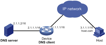
Configuration procedure
Before performing the following configuration, make sure the device and the host can reach each other, and that the IP addresses of the interfaces are configured as shown in Figure 31.
1. Configure the DNS server:
The configuration might vary with DNS servers. The following configuration is performed on a PC running Windows Server 2000.
a. Select Start > Programs > Administrative Tools > DNS.
The DNS server configuration page appears, as shown in Figure 32.
b. Right-click Forward Lookup Zones, select New Zone, and then follow the wizard to create a new zone named com.
Figure 32 Creating a zone
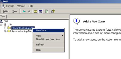
c. On the DNS server configuration page, right-click zone com, and select New Host.
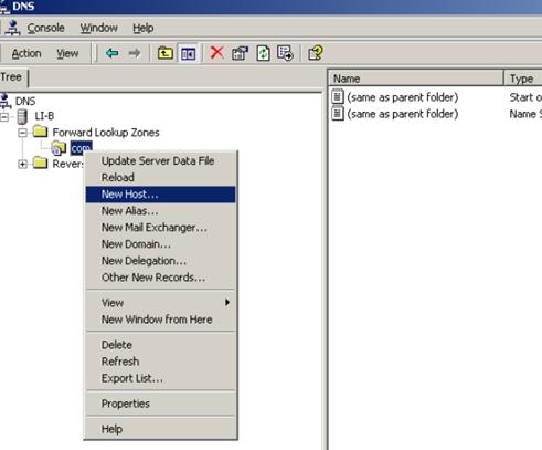
d. On the page that appears, enter host name host and IP address 3.1.1.1.
e. Click Add Host.
The mapping between the IP address and host name is created.
Figure 34 Adding a mapping between domain name and IP address
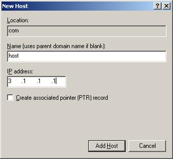
2. Configure the DNS client:
# Specify the DNS server 2.1.1.2.
<Sysname> system-view
[Sysname] dns server 2.1.1.2
# Specify com as the name suffix.
[Sysname] dns domain com
Verifying the configuration
# Use the ping host command on the device to verify that the communication between the device and the host is normal and that the translated destination IP address is 3.1.1.1.
[Sysname] ping host
Ping host.com (3.1.1.1): 56 data bytes, press CTRL_C to break
56 bytes from 3.1.1.1: icmp_seq=0 ttl=255 time=1.000 ms
56 bytes from 3.1.1.1: icmp_seq=1 ttl=255 time=1.000 ms
56 bytes from 3.1.1.1: icmp_seq=2 ttl=255 time=1.000 ms
56 bytes from 3.1.1.1: icmp_seq=3 ttl=255 time=1.000 ms
56 bytes from 3.1.1.1: icmp_seq=4 ttl=255 time=2.000 ms
--- Ping statistics for host ---
5 packet(s) transmitted, 5 packet(s) received, 0.0% packet loss
round-trip min/avg/max/std-dev = 1.000/1.200/2.000/0.400 ms
Troubleshooting IPv4 DNS configuration
Symptom
After enabling dynamic domain name resolution, the user cannot get the correct IP address.
Solution
1. Use the display dns host ip command to verify that the specified domain name is in the cache.
2. If the specified domain name does not exist, check that the DNS client can communicate with the DNS server.
3. If the specified domain name is in the cache, but the IP address is incorrect, check that the DNS client has the correct IP address of the DNS server.
4. Verify that the mapping between the domain name and IP address is correct on the DNS server.
Basic IP forwarding on the device
The device uses the destination IP address of a received packet to find a match from the forwarding information base (FIB) table. It then uses the matching entry to forward the packet.
FIB table
A device selects optimal routes from the routing table, and puts them into the FIB table. Each FIB entry specifies the next hop IP address and output interface for packets destined for a specific subnet or host.
For more information about the routing table, see Layer 3—IP Routing Configuration Guide.
Use the display fib command to display FIB table entries. The following example displays the entire FIB table.
<Sysname> display fib
Destination count: 4 FIB entry count: 4
Flag:
U:Useable G:Gateway H:Host B:Blackhole D:Dynamic S:Static
R:Relay F:FRR
Destination/Mask Nexthop Flag OutInterface/Token Label
10.2.0.0/16 10.2.1.1 U M-GE0/0/0 Null
10.2.1.1/32 127.0.0.1 UH InLoop0 Null
127.0.0.0/8 127.0.0.1 U InLoop0 Null
127.0.0.1/32 127.0.0.1 UH InLoop0 Null
A FIB entry includes the following items:
· Destination—Destination IP address.
· Mask—Network mask. The mask and the destination address identify the destination network. A logical AND operation between the destination address and the network mask yields the address of the destination network. For example, if the destination address is 192.168.1.40 and the mask 255.255.255.0, the address of the destination network is 192.168.1.0. A network mask includes a certain number of consecutive 1s. It can be expressed in dotted decimal format or by the number of the 1s.
· Nexthop—IP address of the next hop.
· Flag—Route flag.
· OutInterface—Output interface.
· Token—MPLS Label Switched Path index number.
· Label—Inner label.
Saving the IP forwarding entries to a file
|
|
IMPORTANT: This feature is available in Release 1138P01 and later versions. |
This feature automatically creates the file if you specify a nonexistent file. If the file already exists, this feature overwrites the file content.
To automatically save the IP forwarding entries periodically, configure a schedule for the device to automatically run the ip forwarding-table save command. For information about scheduling a task, see Fundamentals Configuration Guide.
To save the IP forwarding entries to a file (for Release 1138P01 and later versions):
|
Task |
Command |
Remarks |
|
Specify a file to save the IP forwarding entries. |
ip forwarding-table save filename filename |
Executing this command triggers one-time saving of the IP forwarding entries. Execute this command in any view. |
Displaying FIB table entries
Execute display commands in any view.
|
Task |
Command |
|
Display FIB entries. |
display fib [ vpn-instance vpn-instance-name ] [ ip-address [ mask | mask-length ] ] |
Configuring load sharing
Overview
If a routing protocol finds multiple equal-cost best routes to the same destination, the device forwards packets over the equal-cost routes to implement load sharing.
Configuring load sharing
Load sharing is implemented in the following ways:
· It a routing protocol finds multiple equal-cost best routes, the device implements per-flow load sharing based on the source IP address, destination IP address, source port, destination port, IP protocol, and ingress port.
· In a complex network, a single load sharing algorithm cannot meet the requirements of load sharing. You can implement load sharing by specifying different algorithms.
To configure per-flow load sharing:
|
Step |
Command |
Remarks |
|
1. Enter system view. |
system-view |
N/A |
|
2. Configure per-flow load sharing. |
·
In standalone mode: ·
In IRF mode: |
By default, the device performs per-flow load sharing based on the source IP address, destination IP address, source port, destination port, IP protocol, and ingress port. |
|
|
NOTE: If you configure both five-tuple per-flow load sharing and five-tuple link aggregation load sharing, make sure both load sharing methods use the same five-tuple configuration. |
Displaying the load sharing path selected for a flow
Execute the display command in any view.
|
Task |
Command |
|
Display the load sharing path selected for a flow. |
display ip load-sharing path ingress-port interface-type interface-number packet-format { ipv4oe dest-ip ip-address [ src-ip ip-address ] | ipv6oe dest-ipv6 ipv6-address [ src-ipv6 ipv6-address ] } [ dest-port port-id | ip-pro protocol-id | src-port port-id | vpn-instance vpn-instance-name ] * |
Load sharing configuration example
Network requirements
As shown in Figure 35, Switch A has two equal-cost routes to Switch B. Configure load sharing on Switch A to forward packets through Switch B to the destination IP address 1.2.3.4/24.
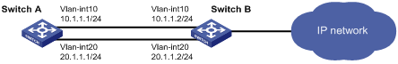
Configuration procedure
# On Switch A, assign FortyGigE 1/0/5 to VLAN 10, and FortyGigE 1/0/6 to VLAN 20.
<SwitchA> system-view
[SwitchA] vlan 10
[SwitchA-vlan10] port fortygige 1/0/5
[SwitchA-vlan10] quit
[SwitchA] vlan 20
[SwitchA-vlan20] port fortygige 1/0/6
[SwitchA-vlan20] quit
# On Switch A, configure IP addresses for VLAN-interface 10 and VLAN-interface 20.
[SwitchA] interface vlan-interface 10
[SwitchA-Vlan-interface10] ip address 10.1.1.1 24
[SwitchA-Vlan-interface10] quit
[SwitchA] interface vlan-interface 20
[SwitchA-Vlan-interface20] ip address 20.1.1.1 24
[SwitchA-Vlan-interface20] quit
# On Switch B, assign FortyGigE 1/0/5 to VLAN 10, and FortyGigE 1/0/6 to VLAN 20.
<SwitchB> system-view
[SwitchB] vlan 10
[SwitchB-vlan10] port fortygige 1/0/5
[SwitchB-vlan10] quit
[SwitchB] vlan 20
[SwitchB-vlan20] port fortygige 1/0/6
[SwitchB-vlan20] quit
# On Switch B, configure IP addresses for VLAN-interface 10 and VLAN-interface 20.
[SwitchB] interface vlan-interface 10
[SwitchB-Vlan-interface10] ip address 10.1.1.2 24
[SwitchB-Vlan-interface10] quit
[SwitchB] interface vlan-interface 20
[SwitchB-Vlan-interface20] ip address 20.1.1.2 24
[SwitchB-Vlan-interface20] quit
# On Switch A, configure two static routes to the destination IP address.
<SwitchA> system-view
[SwitchA] ip route-static 1.2.3.4 24 10.1.1.2
[SwitchA] ip route-static 1.2.3.4 24 20.1.1.
[SwitchA] quit
# On Switch A, display FIB entries matching the destination IP address 1.2.3.4.
<SwitchA>dis fib 1.2.3.4
Destination count: 1 FIB entry count: 2
Flag:
U:Useable G:Gateway H:Host B:Blackhole D:Dynamic S:Static
R:Relay F:FRR
Destination/Mask Nexthop Flag OutInterface/Token Label
1.2.3.0/24 10.1.1.2 USGR Vlan10 Null
1.2.3.0/24 20.1.1.2 USGR Vlan20 Null
# On Switch A, configure per-flow load sharing based on the source IP address and destination IP address.
<SwitchA> system-view
[SwitchA] ip load-sharing mode per-flow dest-ip src-ip
Verifying the configuration
# Verify that Switch A implements load sharing.
[SwitchA] display counters outbound interface fortygige
Interface Total (pkts) Broadcast (pkts) Multicast (pkts) Err (pkts)
FGE1/0/1 0 0 0 0
FGE1/0/2 0 0 0 0
FGE1/0/3 0 0 0 0
FGE1/0/4 0 0 0 0
FGE1/0/5 1045 0 0 0
FGE1/0/6 1044 0 0 0
Configuring IRDP
The term "router" in this chapter refers to a routing-capable device.
The term "host" in this chapter refers to the host that supports IRDP. For example, a host that runs the Linux operating system.
The term "interface" in IRDP collectively refers to Layer 3 interfaces, including VLAN interfaces and Layer 3 Ethernet interfaces. You can set an Ethernet port as a Layer 3 interface by using the port link-mode route command (see Layer 2—LAN Switching Configuration Guide).
Overview
ICMP Router Discovery Protocol (IRDP), an extension of the ICMP, is independent of any routing protocol. It allows hosts to discover the IP addresses of neighboring routers that can act as default gateway to reach devices on other networks.
IRDP enables hosts to track dynamic changes in router availability and requires a minimal amount of manual configuration.
IRDP operation
IRDP uses the following types of ICMP messages:
· Router advertisement (RA)—Sent by a router to advertise IP addresses (including the primary and secondary IP addresses) and preference.
· Router solicitation (RS)—Sent by a host to request the IP addresses of routers on the subnet.
An interface with IRDP enabled periodically broadcasts or multicasts an RA message to advertise its IP addresses. A receiving host adds the IP addresses to its routing table, and selects the IP address with the highest preference as the default gateway.
When a host attached to the subnet starts up, the host multicasts an RS message to request immediate advertisements. If the host does not receive any advertisements, it retransmits the RS several times. If the host does not discover the IP addresses of neighboring routers because of network problems, the host can still discover them from periodic RAs.
IRDP allows hosts to discover neighboring routers, but it does not suggest the best route to a destination. If a host sends a packet to a router that is not the best next hop, the host will receive an ICMP redirect message from the router.
Basic concepts
Preference of an IP address
Every IP address advertised in RAs has a preference value. A larger preference value represents a higher preference. The IP address with the highest preference is selected as the default gateway address.
You can specify the preference for IP addresses to be advertised on a router interface.
An address with the minimum preference value (-2147483648) will not be used as a default gateway address.
Lifetime of an IP address
An RA contains a lifetime field that specifies the lifetime of advertised IP addresses. If the host does not receive a new RA for an IP address within the address lifetime, the host removes the route entry.
All the IP addresses advertised by an interface have the same lifetime.
Advertising interval
A router interface with IRDP enabled sends out RAs at a random interval between the minimum maximum advertising intervals. This mechanism prevents the local link from being overloaded by a large number of RAs sent simultaneously from routers.
As a best practice, shorten the advertising interval on a link that suffers high packet loss rates.
Destination address of RAs
An RA uses either of the following destination IP addresses:
· Broadcast address 255.255.255.255.
· Multicast address 224.0.0.1, which identifies all hosts on the local link.
By default, the destination IP address of an RA is the broadcast address. If all listening hosts in a local area network support IP multicast, specify 224.0.0.1 as the destination IP address.
Proxy-advertised IP addresses
By default, an interface advertises its primary and secondary IP addresses. You can specify IP addresses of other gateways for an interface to proxy-advertise.
Protocols and standards
RFC 1256: ICMP Router Discovery Messages
Configuration procedure
To configure IRDP:
|
Step |
Command |
Remarks |
|
1. Enter system view. |
system-view |
N/A |
|
2. Enter interface view. |
interface interface-type interface-number |
The interface can be a Layer 3 Ethernet interface or VLAN interface. |
|
3. Enable IRDP on the interface. |
ip irdp |
By default, IRDP is disabled. After IRDP is enabled on an interface, the IRDP configuration takes effect, and the device sends RA messages out of the interface. |
|
4. (Optional.) Specify the preference of advertised primary and secondary IP addresses on the interface. |
ip irdp preference preference-value |
The default preference is 0. |
|
5. (Optional.) Set the lifetime of IP addresses to be advertised. |
ip irdp lifetime lifetime-value |
The default lifetime is 1800 seconds. The lifetime applies to all advertised IP addresses, including proxy-advertised IP addresses on the interface. The lifetime cannot be shorter than the maximum advertising interval. |
|
6. (Optional.) Set the maximum and minimum advertising intervals. |
ip irdp interval max-interval-value [ min-interval-value ] |
By default, the maximum interval is 600 seconds, and the minimum interval is 3/4 of the maximum interval. |
|
7. (Optional.) Specify the multicast address 224.0.0.1 as the destination IP address of RAs. |
ip irdp multicast |
By default, RAs use the broadcast address 255.255.255.255 as the destination IP address. |
|
8. (Optional.) Specify a proxy-advertised IP address and its preference. |
ip irdp address ip-address preference-value |
Repeat this step to specify multiple proxy-advertised IP addresses. By default, no IP address is specified. You can specify a maximum of four proxy-advertised IP addresses on an interface. |
IRDP configuration example
Network requirements
As shown in Figure 36, Host A and Host B that run Linux support IRDP, and they are in the internal network. Switch A and Switch B act as the egress routers and connect to external networks 192.168.1.0/24 and 192.168.2.0/24, respectively.
Configure Switch A as the default gateway for the hosts. Packets to the external networks can be correctly routed.
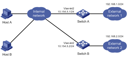
Configuration procedure
1. Configure Switch A:
# Specify an IP address for VLAN-interface 2.
[SwitchA] interface vlan-interface 2
[SwitchA-Vlan-interface2] ip address 10.154.5.1 24
# Enable IRDP on VLAN-interface 2.
[SwitchA-Vlan-interface2] ip irdp
# Specify preference 1000 for advertised IP addresses on VLAN-interface 2.
[SwitchA-Vlan-interface2] ip irdp preference 1000
# Specify the multicast address 224.0.0.1 as the destination IP address for RAs sent by VLAN-interface 2.
[SwitchA-Vlan-interface2] ip irdp multicast
# Specify the IP address 192.168.1.0 and preference 400 for VLAN-interface 2 to proxy-advertise.
[SwitchA-Vlan-interface2] ip irdp address 192.168.1.0 400
2. Configure Switch B:
# Specify an IP address for VLAN-interface 2.
[SwitchB] interface vlan-interface 2
[SwitchB-Vlan-interface2] ip address 10.154.5.2 24
# Enable IRDP on VLAN-interface 2.
[SwitchB-Vlan-interface2] ip irdp
# Specify preference 500 for advertised IP addresses on VLAN-interface 2.
[SwitchB-Vlan-interface2] ip irdp preference 500
# Specify the multicast address 224.0.0.1 as the destination IP address for RAs sent by VLAN-interface 2.
[SwitchB-Vlan-interface2] ip irdp multicast
# Specify the IP address 192.168.2.0 and preference 400 for VLAN-interface 2 to proxy-advertise.
[SwitchB-Vlan-interface2] ip irdp address 192.168.2.0 400
Verifying the configuration
# Display the routing table for Host A.
[HostA@localhost ~]$ netstat -rne
Kernel IP routing table
Destination Gateway Genmask Flags Metric Ref Use Iface
10.154.5.0 0.0.0.0 255.255.255.0 U 0 0 0 eth1
192.168.1.0 0.0.0.0 255.255.255.0 U 0 0 0 eth1
192.168.2.0 0.0.0.0 255.255.255.0 U 0 0 0 eth1
0.0.0.0 10.154.5.1 0.0.0.0 UG 0 0 0 eth1
The output shows that the default route on Host A points to IP address 10.154.5.1, and Host A has routes to 192.168.1.0/24 and 192.168.2.0/24.
# Display the routing table for Host B.
[HostB@localhost ~]$ netstat -rne
Kernel IP routing table
Destination Gateway Genmask Flags Metric Ref Use Iface
10.154.5.0 0.0.0.0 255.255.255.0 U 0 0 0 eth1
192.168.1.0 0.0.0.0 255.255.255.0 U 0 0 0 eth1
192.168.2.0 0.0.0.0 255.255.255.0 U 0 0 0 eth1
0.0.0.0 10.154.5.1 0.0.0.0 UG 0 0 0 eth1
The output shows that the default route on Host B points to IP address 10.154.5.1, and Host B has routes to 192.168.1.0/24 and 192.168.2.0/24.
Optimizing IP performance
|
|
NOTE: The term "interface" in this chapter collectively refers to Layer 3 interfaces, including VLAN interfaces and Layer 3 Ethernet interfaces. You can set an Ethernet port as a Layer 3 interface by using the port link-mode route command (see Layer 2—LAN Switching Configuration Guide). |
Enabling an interface to receive and forward directed broadcasts destined for the directly connected network
A directed broadcast packet is destined for all hosts on a specific network. In the destination IP address of the directed broadcast, the network ID identifies the target network, and the host ID is made up of all ones.
If an interface is allowed to forward directed broadcasts destined for the directly connected network, hackers can exploit this vulnerability to attack the target network. In some scenarios, however, an interface must receive and forward such directed broadcast packets to support UDP helper.
This task enables an interface to accept directed broadcast packets that are destined for and received from the directly connected network to support UDP helper, which converts the directed broadcasts to unicasts and forwards them to a specific server.
Configuration procedure
To enable an interface to receive and forward directed broadcasts destined to the directly connected network:
|
Step |
Command |
Remarks |
|
1. Enter system view. |
system-view |
N/A |
|
2. Enter interface view. |
interface interface-type interface-number |
N/A |
|
3. Enable the interface to receive and forward directed broadcasts destined for the directly connected network. |
ip forward-broadcast |
By default, an interface cannot receive or forward directed broadcasts destined for the directly connected network. |
Configuration example
Network requirements
As shown in Figure 37, the default gateway of the host is the IP address 1.1.1.2/24 of VLAN-interface 3 of the switch.
Enable VLAN-interface 2 to forward directed broadcasts destined for the directly connected network. The server can receive directed broadcasts from the host to IP address 2.2.2.255.
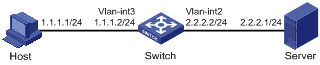
Configuration procedure
# Specify an IP address for VLAN-interface 3.
<Switch> system-view
[Switch] interface vlan-interface 3
[Switch-Vlan-interface3] ip address 1.1.1.2 24
[Switch-Vlan-interface3] quit
# Specify an IP address for VLAN-interface 2, and enable VLAN-interface 2 to forward directed broadcasts destined for the directly connected network.
[Switch] interface vlan-interface 2
[Switch-Vlan-interface2] ip address 2.2.2.2 24
[Switch-Vlan-interface2] ip forward-broadcast
Setting the MTU of IPv4 packets sent over an interface
When a packet exceeds the MTU of IPv4 packets on the output interface, the device processes it in one of the following ways:
· If the packet disallows fragmentation, the device discards it.
· If the packet allows fragmentation, the device fragments it and forwards the fragments.
Fragmentation and reassembling consume system resources, so set the appropriate MTU based on the network environment to avoid fragmentation.
To set the MTU of IPv4 packets sent over an interface:
|
Step |
Command |
Remarks |
|
1. Enter system view. |
system-view |
N/A |
|
2. Enter interface view. |
interface interface-type interface-number |
N/A |
|
3. Set the MTU of IPv4 packets sent over an interface. |
ip mtu mtu-size |
By default, the MTU is not set. |
Setting TCP MSS for an interface
The maximum segment size (MSS) option informs the receiver of the largest segment that the sender can accept. Each end announces its MSS during TCP connection establishment. If the size of a TCP segment is smaller than the MSS of the receiver, TCP sends the TCP segment without fragmentation. If not, it fragments the segment according to the receiver's MSS.
If you set a TCP MSS on an interface, the size of each TCP segment received or sent on the interface cannot exceed the MSS value.
This configuration takes effect only for TCP connections established after the configuration rather than the TCP connections that already exist.
To set a TCP MSS of the interface:
|
Step |
Command |
Remarks |
|
1. Enter system view. |
system-view |
N/A |
|
2. Enter interface view. |
interface interface-type interface-number |
N/A |
|
3. Set a TCP MSS for the interface. |
tcp mss value |
By default, no TCP MSS is set. |
Configuring TCP path MTU discovery
|
|
IMPORTANT: All the devices on a TCP connection must be enabled to send ICMP error messages by using the ip unreachables enable command. |
TCP path MTU discovery (in RFC 1191) discovers the path MTU between the source and destination ends of a TCP connection. It works as follows:
1. A TCP source device sends a packet with the Don't Fragment (DF) bit set.
2. A router that fails to forward the packet because it exceeds the MTU on the outgoing interface discards the packet and returns an ICMP error message, which contains the MTU of the outgoing interface.
3. Upon receiving the ICMP message, the TCP source device calculates the current path MTU of the TCP connection.
4. The TCP source device sends subsequent TCP segments that each are smaller than the MSS (MSS = path MTU – IP header length – TCP header length).
If the TCP source device still receives ICMP error messages when the MSS is smaller than 32 bytes, the TCP source device will fragment packets.
An ICMP error message received from a router that does not support RFC 1191 has the MTU of the outgoing interface set to 0. Upon receiving the ICMP message, the TCP source device selects the path MTU smaller than the current path MTU from the MTU table as described in RFC 1191 to calculate the TCP MSS. The MTU table contains MTUs of 68, 296, 508, 1006, 1280, 1492, 2002, 4352, 8166, 17914, 32000, and 65535 bytes. Because the minimum TCP MSS specified by the system is 32 bytes, the actual minimum MTU is 72 bytes.
After you enable TCP path MTU discovery, all new TCP connections will detect the path MTU. The device uses the path MTU to calculate the MSS to avoid IP fragmentation.
The path MTU uses the following aging mechanism to make sure that the source device can increase the path MTU when the minimum link MTU on the path increases.
· When the TCP source device receives an ICMP error message, it reduces the path MTU and starts an age timer for the path MTU.
· After the age timer expires, the source device uses a larger MSS in the MTU table as described in RFC 1191.
· If no ICMP error message is received within two minutes, the source device increases the MSS again until the MSS is as large as the MSS negotiated during TCP three-way handshake.
To enable TCP path MTU discovery:
|
Step |
Command |
Remarks |
|
1. Enter system view. |
system-view |
N/A |
|
2. Enable TCP path MTU discovery. |
tcp path-mtu-discovery [ aging age-time | no-aging ] |
The default setting is disabled. |
Enabling TCP SYN Cookie
A TCP connection is established through a three-way handshake:
1. The sender sends a SYN packet to the server.
2. The server receives the SYN packet, establishes a TCP semi-connection in SYN_RECEIVED state, and replies with a SYN ACK packet to the sender.
3. The sender receives the SYN ACK packet and replies with an ACK packet. A TCP connection is established.
An attacker can exploit this mechanism to mount SYN Flood attacks. The attacker sends a large number of SYN packets, but does not respond to the SYN ACK packets from the server. As a result, the server establishes a large number of TCP semi-connections and can no longer handle normal services.
SYN Cookie can protect the server from SYN Flood attacks. When the server receives a SYN packet, it responds with a SYN ACK packet without establishing a TCP semi-connection. The server establishes a TCP connection and enters ESTABLISHED state only when it receives an ACK packet from the client.
To enable TCP SYN Cookie:
|
Step |
Command |
Remarks |
|
1. Enter system view. |
system-view |
N/A |
|
2. Enable SYN Cookie. |
tcp syn-cookie enable |
The default setting is disabled. |
Setting the TCP buffer size
|
Step |
Command |
Remarks |
|
1. Enter system view. |
system-view |
N/A |
|
2. Set the size of TCP receive/send buffer. |
tcp window window-size |
The default buffer size is 64 KB. |
Setting TCP timers
You can set the following TCP timers:
· SYN wait timer—TCP starts the SYN wait timer after sending a SYN packet. If no response packet is received within the SYN wait timer interval, TCP fails to establish the connection.
· FIN wait timer—TCP starts the FIN wait timer when the state changes to FIN_WAIT_2. If no FIN packet is received within the timer interval, TCP terminates the connection. If a FIN packet is received, TCP changes connection state to TIME_WAIT. If a non-FIN packet is received, TCP restarts the timer, and tears down the connection when the timer expires.
To set TCP timers:
|
Step |
Command |
Remarks |
|
1. Enter system view. |
system-view |
N/A |
|
2. Set TCP timers. |
·
Set the TCP SYN wait
timer: ·
Set the TCP FIN wait
timer: |
By default: · The TCP SYN wait timer is 75 seconds. · The TCP FIN wait timer is 675 seconds. |
Enabling sending ICMP error messages
Perform this task to enable sending ICMP error messages, including redirect, time-exceeded, and destination unreachable messages.
· ICMP redirect messages
A host that has only one default route sends all packets to the default gateway. The default gateway sends an ICMP redirect message to inform the host of a correct next hop by following these rules:
? The receiving and sending interfaces are the same.
? The selected route is not created or modified by any ICMP redirect messages.
? The selected route is not destined for 0.0.0.0.
? There is no source route option in the received packet.
ICMP redirect messages simplify host management and enable hosts to gradually optimize their routing table.
· ICMP time-exceeded messages
A device sends ICMP time-exceeded messages by following these rules:
? If a received packet is not destined for the device and the TTL field of the packet is 1, the device sends an ICMP TTL Expired in Transit message to the source.
? When the device receives the first fragment of an IP datagram destined for it, it starts a timer. If the timer expires before all the fragments of the datagram are received, the device sends an ICMP Fragment Reassembly Timeout message to the source.
· ICMP destination unreachable messages
A device sends ICMP destination unreachable messages by following these rules:
? If a packet does not match any route and there is no default route in the routing table, the device sends a Network Unreachable ICMP error message to the source.
? If a packet is destined for the device but the transport layer protocol of the packet is not supported by the device, the device sends a Protocol Unreachable ICMP error message to the source.
|
|
NOTE: If a DHCP enabled device receives an ICMP echo reply without sending any ICMP echo requests, the device does not send any Protocol Unreachable ICMP error messages to the source. For more information about DHCP, see Layer 3—IP Services Configuration Guide. |
? If a UDP packet is destined for the device but the packet's port number does not match the corresponding process, the device sends the source a Port Unreachable ICMP error message.
? If the source uses Strict Source Routing to send packets, but the intermediate device finds that the next hop specified by the source is not directly connected, the device sends the source a Source Routing Failure ICMP error message.
? If the MTU of the sending interface is smaller than the packet and the packet has DF set, the device sends the source a Fragmentation Needed and DF-set ICMP error message.
To enable sending ICMP error messages:
|
Step |
Command |
Remarks |
|
1. Enter system view. |
system-view |
N/A |
|
2. Enable sending ICMP error messages. |
·
Enable sending ICMP redirect messages: ·
Enable sending ICMP time-exceeded messages: ·
Enable sending ICMP destination
unreachable messages: |
The default settings are disabled. |
Sending ICMP error messages facilitates network management, but sending excessive ICMP messages increases network traffic. A device's performance degrades if it receives a lot of malicious ICMP messages that cause it to respond with ICMP error messages.
To prevent such problems, you can disable the device from sending ICMP error messages. A device that is disabled from sending ICMP time-exceeded messages does not send ICMP TTL Expired messages. However, it can still send ICMP Fragment Reassembly Timeout messages.
Disabling forwarding ICMP fragments
Disabling forwarding ICMP fragments can protect your device from ICMP fragments attacks.
To disable forwarding ICMP fragments:
|
Step |
Command |
Remarks |
|
1. Enter system view. |
system-view |
N/A |
|
2. Disable forwarding ICMP fragments. |
ip icmp fragment discarding |
By default, forwarding ICMP fragments is enabled. |
Configuring rate limit for ICMP error messages
To avoid sending excessive ICMP error messages within a short period that might cause network congestion, you can limit the rate at which ICMP error messages are sent. A token bucket algorithm is used with one token representing one ICMP error message. Tokens are placed in the bucket at a specific interval until the maximum number of tokens that the bucket can hold is reached. Tokens are removed from the bucket when ICMP error messages are sent. When the bucket is empty, ICMP error messages are not sent until a new token is placed in the bucket.
To configure rate limit for ICMP error messages:
|
Step |
Command |
Remarks |
|
1. Enter system view. |
system-view |
N/A |
|
2. Set the interval and bucket size for ICMP error messages |
ip icmp error-interval milliseconds [ bucketsize ] |
By default, the bucket allows a maximum of 10 tokens, and tokens are placed in the bucket at the interval of 100 milliseconds. To disable the ICMP rate limit, set the interval to 0 milliseconds. |
Specifying the source address for ICMP packets
Perform this task to specify the source IP address for outgoing ping echo request and ICMP error messages. As a best practice, specify the IP address of the loopback interface as the source IP address. This feature helps users to locate the sending device easily.
If you specify an IP address in the ping command, ping echo requests use the specified address as the source IP address rather than the IP address specified by the ip icmp source command.
To specify the source IP address for ICMP packets:
|
Step |
Command |
Remarks |
|
1. Enter system view. |
system-view |
N/A |
|
2. Specify the source address for outgoing ICMP packets. |
ip icmp source [ vpn-instance vpn-instance-name ] ip-address |
By default, the device uses the IP address of the sending interface as the source IP address for outgoing ICMP packets. |
Displaying and maintaining IP performance optimization
Execute display commands in any view and reset commands in user view.
|
Task |
Command |
|
Display brief information about RawIP connections (in standalone mode). |
display rawip [ slot slot-number ] |
|
Display brief information about RawIP connections (in IRF mode). |
display rawip [ chassis chassis-number slot slot-number ] |
|
Display detailed information about RawIP connections (in standalone mode). |
display rawip verbose [ slot slot-number [ pcb pcb-index ] ] |
|
Display detailed information about RawIP connections (in IRF mode). |
display rawip verbose [ chassis chassis-number slot slot-number [ pcb pcb-index ] ] |
|
Display brief information about TCP connections (in standalone mode). |
display tcp [ slot slot-number ] |
|
Display brief information about TCP connections (in IRF mode). |
display tcp [ chassis chassis-number slot slot-number ] |
|
Display detailed information about TCP connections (in standalone mode). |
display tcp verbose [ slot slot-number [ pcb pcb-index ] ] |
|
Display detailed information about TCP connections (in IRF mode). |
display tcp verbose [ chassis chassis-number slot slot-number [ pcb pcb-index ] ] |
|
Display brief information about UDP connections (in standalone mode). |
display udp [ slot slot-number ] |
|
Display brief information about UDP connections (in IRF mode). |
display udp [ chassis chassis-number slot slot-number ] |
|
Display detailed information about UDP connections (in standalone mode). |
display udp verbose [ slot slot-number [ pcb pcb-index ] ] |
|
Display detailed information about UDP connections (in IRF mode). |
display udp verbose [ chassis chassis-number slot slot-number [ pcb pcb-index ] ] |
|
Display IP packet statistics (in standalone mode). |
display ip statistics [ slot slot-number ] |
|
Display IP packet statistics (in IRF mode). |
display ip statistics [ chassis chassis-number slot slot-number ] |
|
Display TCP traffic statistics (in standalone mode). |
display tcp statistics [ slot slot-number ] |
|
Display TCP traffic statistics (in IRF mode). |
display tcp statistics [ chassis chassis-number slot slot-number ] |
|
Display UDP traffic statistics (in standalone mode). |
display udp statistics [ slot slot-number ] |
|
Display UDP traffic statistics (in IRF mode). |
display udp statistics [ chassis chassis-number slot slot-number ] |
|
Display ICMP statistics (in standalone mode). |
display icmp statistics [ slot slot-number ] |
|
Display ICMP statistics (in IRF mode). |
display icmp statistics [ chassis chassis-number slot slot-number ] |
|
Clear IP packet statistics (in standalone mode). |
reset ip statistics [ slot slot-number ] |
|
Clear IP packet statistics (in IRF mode). |
reset ip statistics [ chassis chassis-number slot slot-number ] |
|
Clear TCP traffic statistics. |
reset tcp statistics |
|
Clear UDP traffic statistics. |
reset udp statistics |
Configuring UDP helper
Overview
UDP helper can provide the following packet conversion for packets with specific UDP destination port numbers:
· Convert broadcast to unicast, and forward the unicast packets to specific destinations.
· Convert broadcast to multicast, and forward the multicast packets.
|
|
NOTE: The term "interface" in this chapter collectively refers to VLAN interfaces, Layer 3 Ethernet interfaces and subinterfaces, and Layer 3 aggregate interfaces and subinterfaces. You can set an Ethernet port as a Layer 3 interface by using the port link-mode route command (see Layer 2—LAN Switching Configuration Guide). |
Configuration restrictions and guidelines
When you configure UDP helper, follow these restrictions and guidelines:
· By default, an interface on the device does not receive directed broadcasts destined for the directly connected network. To use UDP helper, execute the ip forward-broadcast command. For more information about receiving directed broadcasts destined for the directly connected network, see "Optimizing IP performance."
· Do not set UDP ports 67 and 68 for UDP helper, because UDP helper cannot forward DHCP broadcast packets.
· You can specify a maximum of 256 UDP ports for UDP helper.
· You can specify a maximum of 20 unicast and multicast addresses for UDP helper to convert broadcast packets on an interface.
Configuring UDP helper to convert broadcast to unicast
You can configure UDP helper to convert broadcast packets with specific UDP port numbers to unicast packets.
Upon receiving a UDP broadcast packet, UDP helper uses the configured UDP ports to match the UDP destination port number of the packet.
· If a match is found, UDP helper duplicates the packet and modifies the destination IP address of the copy to the configured unicast address. Then UDP helper forwards the unicast packet to the unicast address.
· If no match is found, UDP helper does not process the packet.
To configure UDP helper to convert broadcast to unicast:
|
Step |
Command |
Remarks |
|
1. Enter system view. |
system-view |
N/A |
|
2. Enable UDP helper. |
udp-helper enable |
By default, UDP helper is disabled. |
|
3. Specify a UDP port. |
udp-helper port { port-number | dns | netbios-ds | netbios-ns | tacacs | tftp | time } |
By default, no UDP port is specified. |
|
4. Enter interface view. |
interface interface-type interface-number |
N/A |
|
5. Specify a destination server for UDP helper to convert broadcast to unicast. |
udp-helper server ip-address [ global | vpn-instance vpn-instance-name ] |
By default, no destination server is specified. If you specify multiple destination servers, UDP helper creates one copy for each server. Use this command on the interface that receives broadcast packets. |
Configuring UDP helper to convert broadcast to multicast
You can configure UDP helper to convert broadcast packets with specific UDP port numbers to multicast packets.
Upon receiving a UDP broadcast packet, UDP helper uses the configured UDP ports to match the UDP destination port number of the packet.
· If a match is found, UDP helper duplicates the packet and modifies the destination IP address of the copy to the configured multicast address. Then UDP helper forwards the packet to the multicast group.
· If no match is found, UDP helper does not process the packet.
To configure UDP helper to convert broadcast to multicast:
|
Step |
Command |
Remarks |
|
1. Enter system view. |
system-view |
N/A |
|
2. Enable UDP helper. |
udp-helper enable |
By default, UDP helper is disabled. |
|
3. Specify a UDP port. |
udp-helper port { port-number | dns | netbios-ds | netbios-ns | tacacs | tftp | time } |
By default, no UDP port is specified. |
|
4. Enter interface view. |
interface interface-type interface-number |
N/A |
|
5. Specify a destination multicast address for UDP helper to convert broadcast to multicast. |
udp-helper broadcast-map multicast-address [ acl acl-number ] |
By default, no destination multicast address is specified for UDP helper. If you specify multiple multicast addresses, UDP helper creates one copy for each address. Use this command on the interface that receives broadcast packets. |
Displaying and maintaining UDP helper
Execute display command in any view and reset command in user view.
|
Task |
Command |
|
Display information about broadcast to unicast conversion by UDP helper on an interface. |
display udp-helper interface interface-type interface-number |
|
Clear packet statistics for UDP helper. |
reset udp-helper statistics |
UDP helper configuration examples
Configuring UDP helper to convert broadcast to unicast
Network requirements
As shown in Figure 38, configure UDP helper to convert broadcast to unicast on VLAN-interface 1 of Switch A. This feature enables Switch A to forward broadcast packets with UDP destination port number 55 to the destination server 10.2.1.1/16.
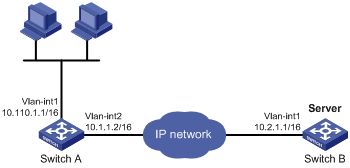
Configuration procedure
Make sure Switch A can reach the subnet 10.2.0.0/16.
# Enable UDP helper.
[SwitchA] System-view
[SwitchA] udp-helper enable
# Enable UDP helper to forward broadcast packets with the UDP destination port 55.
[SwitchA] udp-helper port 55
# Specify the destination server 10.2.1.1 on VLAN-interface 1.
[SwitchA] interface vlan-interface 1
[SwitchA-Vlan-interface1] ip address 10.110.1.1 16
[SwitchA-Vlan-interface1] udp-helper server 10.2.1.1
Verifying the configuration
# Display information about broadcast to unicast conversion by UDP helper on VLAN-interface 1.
[SwitchA-Vlan-interface1] display udp-helper interface vlan-interface 1
Interface Server VPN instance Server address Packets sent
Vlan-interface1 N/A 10.2.1.1 5
Configuring UDP helper to convert broadcast to multicast
Network requirements
As shown in Figure 39, VLAN-interface 1 of Switch B can receive multicast packets destined to 225.1.1.1.
Configure UDP helper to convert broadcast to multicast on VLAN-interface 1 of Switch A. This feature enables Switch A to forward broadcast packets with UDP destination port number 55 to the multicast group 225.1.1.1.
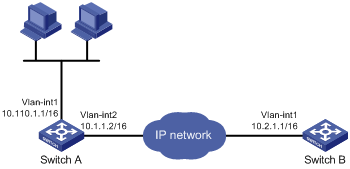
Configuration procedure
Make sure Switch A can reach the subnet 10.2.0.0/16.
# Enable UDP helper.
<SwitchA> system-view
[SwitchA] udp-helper enable
# Enable UDP helper to forward broadcast packets with the UDP destination port 55.
[SwitchA] udp-helper port 55
# Configure UDP helper to convert broadcast packets to multicast packets destined for 225.1.1.1.
[SwitchA] interface vlan-interface 1
[SwitchA-Vlan-interface1] ip address 10.110.1.1 16
[SwitchA-Vlan-interface1] udp-helper broadcast-map 225.1.1.1
[SwitchA-Vlan-interface1] quit
# Enable IP multicast routing globally.
[SwitchA] multicast routing
[SwitchA-mrib] quit
Enable PIM-DIM and IGMP on VLAN-interface 1.
[SwitchA] interface vlan-interface 1
[SwitchA-Vlan-interface1] pim dm
[SwitchA-Vlan-interface1] igmp enable
# Configure VLAN-interface 1 as a static member of the multicast group 225.1.1.1.
[SwitchA-Vlan-interface1] igmp static-group 225.1.1.1
[SwitchA-Vlan-interface1] quit
# Enable PIM-DIM and IGMP on VLAN-interface 2.
[SwitchA] interface vlan-interface 2
[SwitchA-Vlan-interface2] pim dm
[SwitchA-Vlan-interface2] igmp enable
# Configure VLAN-interface 2 as a static member of the multicast group 225.1.1.1.
[SwitchA-Vlan-interface2] igmp static-group 225.1.1.1
Verifying the configuration
Verify that you can capture multicast packets from Switch A on Switch B.
A
address
DHCP address assignment, 29
DHCP address pool, 29
DHCP address pool application on interface, 40
DHCP address pool selection, 30
DHCP address pool VPN instance application, 43
DHCP allocation, 23
DHCP client duplicated address detection, 61
DHCP IP address allocation sequence, 30
DHCP IP address conflict detection, 41
DHCP IP address lease extension, 24
DHCP server address pool, 31
DHCP server address pool creation, 32
DHCP server address pool IP address range, 32
ICMP packet source address, 99
IP address classes, 17
IP addressing configuration, 17, 20
IP addressing interface IP address, 18
special IP addresses, 18
Address Resolution Protocol. Use ARP
advertising
IRDP proxy-advertised IP address, 89
IRDP RA (router advertisement), 89
allocating
DHCP address allocation, 29
DHCP addresses allocation, 23
DHCP IP address allocation sequence, 30
applying
DHCP address pool on interface, 40
DHCP address pool to VPN instance, 43
common proxy ARP configuration, 15
common proxy ARP enable, 14
configuration, 1, 8
configuration (multiport entry), 9
customer-side port configuration, 6
displaying, 7
dynamic entry aging timer configuration, 5
dynamic entry check enable, 6
dynamic entry max number max number (for device), 4
dynamic entry max number max number (for interface), 5
dynamic table entry, 2
entry synchronization, 7
gratuitous ARP configuration, 11, 12
gratuitous ARP IP conflict notification, 12
gratuitous ARP packet learning, 11
gratuitous ARP periodic packet send, 11
local proxy ARP enable, 14
logging enable, 6
maintaining, 7
message format, 1
multiport entry configuration, 4
OpenFlow table entry, 3
operation, 1
proxy ARP configuration, 14
Rule entry, 3
static configuration, 8
static entry configuration, 3
static table entry, 2
table, 2
assigning
DHCP address, 29
IP addressing interface IP address, 18
auto
DHCP automatic address allocation, 23
DHCP client auto-configuration file, 37
DHCP snooping entry auto backup, 69
B
backing up
DHCP snooping entries, 69
BIMS server information (DHCP client), 37
BOOTP
DHCP server BOOTP request ignore, 42
DHCP server BOOTP response format, 42
broadcast
DHCP server broadcast response, 42
IP services UDP helper configuration, 101
UDP helper broadcast to multicast conversion, 102, 104
UDP helper broadcast to unicast conversion, 101, 103
UDP helper configuration, 103
buffer
TCP buffer size, 96
C
class
IP address class, 17
client
DHCP client auto-configuration file, 37
DHCP client BIMS server information, 37
DHCP client configuration, 60, 62
DHCP client display, 61
DHCP client DNS server, 36
DHCP client domain name suffix, 36
DHCP client duplicated address detection, 61
DHCP client enable (interface), 60
DHCP client gateway, 35
DHCP client ID configuration (interface), 60
DHCP client NetBIOS node type, 36
DHCP client packet DSCP value, 61
DHCP client WINS server, 36
DHCP server specification, 38
DHCP snooping Option 82 support, 66
DHCP voice client Option 184 parameters, 38
common
DHCP options, 26
configuring
DHCP client, 60, 62
DHCP client auto-configuration file, 37
DHCP client ID (interface), 60
DHCP IP address conflict detection, 41
DHCP relay agent, 51, 52, 57
DHCP relay agent IP address release, 55
DHCP relay agent Option 82, 56, 58, 73
DHCP relay agent security features, 54
DHCP server, 29, 31
DHCP server address pool, 31
DHCP server BOOTP request ignore, 42
DHCP server BOOTP response format, 42
DHCP server broadcast response, 42
DHCP server compatibility, 42
DHCP server configuration, 45
DHCP server IP address dynamic assignment, 46
DHCP server IP address static assignment, 45
DHCP server option customization, 49
DHCP server user class, 47
DHCP snooping, 65, 67, 73
DHCP snooping basics, 67, 73
DHCP snooping Option 82 configuration, 68
DHCP snooping packet rate limit, 71
DHCP voice client Option 184 parameters, 38
directed broadcast forward, 93
DNS, 75, 76
DNS trusted interface, 78
ICMP error message rate limit, 98
interface TCP MSS, 94
IP addressing, 17, 20
IP forwarding load sharing, 86, 87
IP services ARP, 1, 8
IP services ARP (multiport entry), 9
IP services ARP (static), 8
IP services ARP customer-side port, 6
IP services ARP dynamic entry aging timer, 5
IP services ARP multiport entry, 4
IP services ARP static entry, 3
IP services common proxy ARP, 15
IP services gratuitous ARP, 11, 12
IP services proxy ARP, 14
IP services UDP helper, 101
IPPO interface MTU, 94
IPv4 DNS, 79
IPv4 DNS client, 76
IPv4 DNS client dynamic domain name resolution, 77, 80
IPv4 DNS client static domain name resolution, 76, 79
IRDP, 89, 90, 91
TCP buffer size, 96
TCP path MTU discovery, 95
TCP timers, 96
UDP helper, 103
UDP helper broadcast to multicast conversion, 102, 104
UDP helper broadcast to unicast conversion, 101, 103
cookie (TCP SYN), 96
creating
DHCP server address pool, 32
customer
IP services ARP customer-side port configuration, 6
customizing
DHCP options, 26, 39
DHCP server option customization, 49
D
detecting
DHCP client duplicated address detection, 61
DHCP IP address conflict detection, 41
device
DHCP client packet DSCP value, 61
DHCP overview, 23
DHCP relay agent packet DSCP value, 56
DHCP server configuration, 29, 31
DHCP server packet DSCP value, 43
DHCP snooping entry max, 71
directed broadcast forward configuration, 93
DNS outgoing packet DSCP value, 78
DNS packet source interface, 78
DNS trusted interface, 78
ICMP error message send, 97
ICMP fragment forwarding disable, 98
interface TCP MSS configuration, 94
IP addressing configuration, 20
IP forwarding basics, 84
IP services ARP dynamic entry max number (for device), 4
IP services ARP dynamic entry max number (for interface), 5
IP services common proxy ARP configuration, 15
IPPO interface MTU configuration, 94
IPv4 DNS client configuration, 76
TCP buffer size, 96
TCP path MTU discovery, 95
TCP SYN cookie, 96
TCP timer, 96
UDP helper broadcast to multicast conversion, 104
UDP helper broadcast to unicast conversion, 103
UDP helper configuration, 103
address allocation, 23
address assignment, 29
address pool, 29
address pool application on interface, 40
address pool selection, 30
address pool VPN instance application, 43
client auto-configuration file, 37
client BIMS server information, 37
client configuration, 60, 62
client display, 61
client DNS server, 36
client domain name suffix, 36
client duplicated address detection, 61
client enable (interface), 60
client gateway specification, 35
client ID configuration (interface), 60
client NetBIOS node type, 36
client packet DSCP value, 61
client server specification, 38
client WINS server specification, 36
enable, 40
enabling Option 82 handling, 41
IP address allocation, 24
IP address allocation sequence, 30
IP address conflict detection, 41
IP address lease extension, 24
message format, 25
Option #, 26, See also Option #
Option 121, 26
Option 150, 26
Option 184 (reserved), 26, 28
Option 3;Option 003, 26
Option 33;Option 033, 26
Option 43 (vendor-specific);Option 043 (vendor-specific), 26, 26
Option 51;Option 051, 26
Option 53;Option 053, 26
Option 55;Option 055, 26
Option 6;Option 006, 26
Option 60;Option 060, 26
Option 66;Option 066, 26
Option 67;Option 067, 26
Option 82 (relay agent);Option 082 (relay agent), 26, 27
option customization, 39
options (common), 26
options (custom), 26
overview, 23
protocols and standards, 28
relay agent configuration, 51, 52, 57
relay agent display, 57
relay agent enable (on interface), 53
relay agent entry periodic refresh, 54
relay agent IP address release, 55
relay agent maintain, 57
relay agent operation, 51
relay agent Option 82 configuration, 56, 58, 73
relay agent Option 82 support, 52
relay agent packet DSCP value, 56
relay agent relay entry recording, 54
relay agent security features, 54
relay agent starvation attack protection, 55
server address pool configuration, 31
server address pool creation, 32
server address pool IP address range, 32
server BOOTP request ignore, 42
server BOOTP response format, 42
server broadcast response, 42
server compatibility configuration, 42
server configuration, 29, 31, 45
server display, 44
server enable on interface, 40
server IP address dynamic assignment, 46
server IP address static assignment, 45
server maintain, 44
server option customization configuration, 49
server packet DSCP value, 43
server specification (relay agent), 53
server user class configuration, 47
snooping. See DHCP snooping
troubleshoot relay agent configuration, 59
troubleshoot server configuration, 49
voice client Option 184 parameters, 38
basic configuration, 67
basics configuration, 73
configuration, 65, 67, 73
DHCP-REQUEST message attack protection, 70
display, 72
entry auto backup, 69
entry max, 71
maintain, 72
Option 82 configuration, 68
Option 82 support, 66
packet rate limit, 71
starvation attack protection, 70
trusted port, 65
untrusted port, 65
DHCP-REQUEST message attack protection, 70
disabling
ICMP fragment forwarding, 98
displaying
DHCP client, 61
DHCP relay agent, 57
DHCP server, 44
DHCP snooping, 72
IP addressing, 20
IP forwarding FIB table entries, 85
IP performance optimization, 99
IP services ARP, 7
IP services proxy ARP, 14
IPv4 DNS, 79
UDP helper, 103
configuration, 75, 76
DHCP client domain name suffix, 36
DHCP client server, 36
dynamic domain name resolution, 75
IPv4 client configuration, 76
IPv4 client dynamic domain name resolution, 77, 80
IPv4 client static domain name resolution, 76, 79
IPv4 configuration, 79
IPv4 DNS display, 79
IPv4 DNS maintain, 79
outgoing packet DSCP value, 78
packet source interface, 78
static domain name resolution, 75
suffixes, 76
troubleshoot IPv4 DNS configuration, 82
troubleshoot IPv4 DNS incorrect IP address, 82
trusted interface configuration, 78
domain
DHCP client domain name suffix, 36
name system. Use DNS
DSCP
DHCP client packet DSCP value, 61
DHCP relay agent packet DSCP value, 56
DHCP server packet DSCP value, 43
DNS outgoing packet DSCP value, 78
duplicate
DHCP client duplicated address detection, 61
dynamic
DHCP address allocation, 23, 29
DHCP relay agent entry periodic refresh, 54
DHCP server IP address assignment, 46
DHCP server user class configuration, 47
DNS domain name resolution, 75
IP services ARP dynamic entry, 5
IP services ARP entry max number (for device), 4
IP services ARP entry max number (for interface), 5
IP services ARP table entry, 2
IPv4 DNS client dynamic domain name resolution, 77, 80
Dynamic Host Configuration Protocol. Use DHCP
E
enabling
DHCP, 40
DHCP client (interface), 60
DHCP client duplicated address detection, 61
DHCP Option 82 handling, 41
DHCP relay agent (on interface), 53
DHCP relay agent entry periodic refresh, 54
DHCP relay agent relay entry recording, 54
DHCP relay agent starvation attack protection, 55
DHCP server on interface, 40
DHCP snooping starvation attack protection, 70
DHCP-REQUEST message attack protection, 70
directed broadcast receive/forward, 93
ICMP error message send, 97
IP services ARP dynamic entry check, 6
IP services ARP logging, 6
IP services common proxy ARP, 14
IP services gratuitous ARP IP conflict notification, 12
IP services local proxy ARP, 14
TCP SYN cookie, 96
error
IP performance optimization ICMP error message sending, 97
Ethernet
DHCP client configuration, 60, 62
DHCP server configuration, 29, 31, 45
DHCP server IP address dynamic assignment, 46
DHCP server IP address static assignment, 45
DHCP server option customization, 49
DHCP server user class configuration, 47
DHCP snooping basic configuration, 73
IP services ARP configuration, 1, 8
IP services ARP configuration (multiport entry), 9
IP services ARP static configuration, 8
IP services common proxy ARP configuration, 15
IP services gratuitous ARP configuration, 11
IP services proxy ARP configuration, 14
IP services UDP helper configuration, 101
UDP helper broadcast to multicast conversion, 102
UDP helper broadcast to unicast conversion, 101
UDP helper configuration, 103
extending
DHCP IP address lease extension, 24
F
FIB
IP forwarding basics (on device), 84
IP routing table, 84
table entry display, 85
FIN wait timer, 96
format
DHCP message, 25
DHCP server BOOTP response format, 42
IP services ARP message format, 1
fragment
IP performance optimization ICMP fragment forwarding, 98
G
gateway
DHCP client gateway specification, 35
gratuitous ARP
configuration, 11, 12
IP conflict notification, 12
packet learning, 11
periodic packet send, 11
I
ICMP
error message rate limit, 98
error message send, 97
fragment forwarding disable, 98
IRDP configuration, 89, 90, 91
packet source address, 99
packet source address specification, 99
Router Discovery Protocol. Use IRDP
ID
IP address class Host ID, 17
IP address class Net ID, 17
ignoring
DHCP server BOOTP request, 42
instance
DHCP address pool VPN instance application, 43
IP addressing
address classes, 17
ARP OpenFlow table entry, 3
ARP Rule entry, 3
configuration, 17, 20
DHCP address allocation, 23, 24
DHCP address allocation sequence, 30
DHCP address assignment, 29
DHCP address conflict detection, 41
DHCP address pool, 29
DHCP address pool VPN instance application, 43
DHCP client configuration, 60, 62
DHCP lease extension, 24
DHCP message format, 25
DHCP relay agent IP address release, 55
DHCP server address pool IP address range, 32
DHCP server configuration, 45
DHCP server IP address dynamic assignment, 46
DHCP server IP address static assignment, 45
DHCP server option customization, 49
DHCP server user class configuration, 47
DHCP snooping basic configuration, 67
DHCP snooping configuration, 65, 67, 73
displaying, 20
DNS configuration, 75, 76
DNS dynamic domain name resolution, 75
DNS packet source interface, 78
DNS static domain name resolution, 75
DNS trusted interface, 78
forwarding basics (on device), 84
interface IP address assignment, 18
IP services ARP configuration, 1, 8
IP services ARP configuration (multiport entry), 9
IP services ARP dynamic entry aging timer configuration, 5
IP services ARP dynamic entry check enable, 6
IP services ARP dynamic entry max number (for device), 4
IP services ARP dynamic entry max number (for interface), 5
IP services ARP dynamic table entry, 2
IP services ARP message format, 1
IP services ARP multiport entry configuration, 4
IP services ARP operation, 1
IP services ARP static configuration, 8
IP services ARP static entry configuration, 3
IP services ARP static table entry, 2
IP services ARP table, 2
IP services common proxy ARP configuration, 15
IP services gratuitous ARP configuration, 11, 12
IP services gratuitous ARP IP conflict notification, 12
IP services gratuitous ARP packet learning, 11
IP services gratuitous ARP periodic packet send, 11
IP services proxy ARP configuration, 14
IRDP configuration, 89, 90, 91
IRDP primary IP address, 89
IRDP proxy-advertised IP address, 89
masking, 18
special IP addresses, 18
subnetting, 18
IP addressing IRDP
secondary IP address, 89
IP forwarding
device basics, 84
FIB table, 84
FIB table entry display, 85
IP forwarding entry save, 84
load sharing, 86, 87
optimal route selection, 84
IP performance optimization
configuration, 93
directed broadcast forward configuration, 93
directed broadcast receive/forward enable, 93
displaying, 99
ICMP error message rate limit, 98
ICMP error message send, 97
ICMP fragment forwarding disable, 98
ICMP packet source address, 99
interface TCP MSS configuration, 94
maintaining, 99
TCP buffer size, 96
TCP path MTU discovery, 95
TCP SYN cookie, 96
TCP timer, 96
IP services
DHCP address allocation, 23, 24
DHCP address allocation sequence, 30
DHCP address pool, 29
DHCP address pool application on interface, 40
DHCP address pool VPN instance application, 43
DHCP client BIMS server information, 37
DHCP client DNS server, 36
DHCP client domain name suffix, 36
DHCP client gateway, 35
DHCP client NetBIOS node type, 36
DHCP client server specification, 38
DHCP client WINS server, 36
DHCP enable, 40
DHCP IP address conflict detection, 41
DHCP IP address lease extension, 24
DHCP message format, 25
DHCP Option 82 handling, 41
DHCP option customization, 39
DHCP options (common), 26
DHCP options (custom), 26
DHCP overview, 23
DHCP protocols and standards, 28
DHCP relay agent configuration, 51, 52, 57
DHCP relay agent enable (on interface), 53
DHCP relay agent entry periodic refresh, 54
DHCP relay agent IP address release, 55
DHCP relay agent operation, 51
DHCP relay agent Option 82, 58, 73
DHCP relay agent Option 82 configuration, 56
DHCP relay agent Option 82 support, 52
DHCP relay agent relay entry recording, 54
DHCP relay agent security features, 54
DHCP relay agent starvation attack protection, 55
DHCP server (relay agent), 53
DHCP server address pool, 31, 32
DHCP server address pool IP address range, 32
DHCP server compatibility configuration, 42
DHCP server configuration, 29, 31, 45
DHCP server display, 44
DHCP server enable on interface, 40
DHCP server IP address dynamic assignment, 46
DHCP server IP address static assignment, 45
DHCP server maintain, 44
DHCP server option customization, 49
DHCP server user class configuration, 47
DHCP snooping basic configuration, 73
DHCP snooping configuration, 65
DHCP snooping display, 72
DHCP snooping entry auto backup, 69
DHCP snooping maintain, 72
DHCP snooping Option 82 configuration, 68
DHCP snooping Option 82 support, 66
DHCP snooping packet rate limit, 71
DHCP snooping starvation attack protection, 70
DHCP snooping trusted port, 65
DHCP snooping untrusted port, 65
DHCP voice client Option 184 parameter, 38
DHCP-REQUEST message attack protection, 70
DNS configuration, 75, 76
DNS outgoing packet DSCP value, 78
DNS packet source interface, 78
DNS trusted interface, 78
forwarding basics (on device), 84
IP forwarding FIB table, 84
IP forwarding load sharing, 86, 87
IPv4 DNS configuration, 79
IRDP configuration, 89, 90, 91
IRDP operation, 89
troubleshooting DHCP relay agent configuration, 59
troubleshooting DHCP server configuration, 49
troubleshooting IPv4 DNS configuration, 82
troubleshooting IPv4 DNS incorrect IP address, 82
UDP helper broadcast to multicast conversion, 102, 104
UDP helper broadcast to unicast conversion, 101, 103
UDP helper configuration, 101, 103
UDP helper display, 103
UDP helper maintain, 103
IPPO
interface MTU configuration, 94
IP-to-MAC
DHCP snooping configuration, 65, 67, 73
IPv4
DNS client configuration, 76
DNS configuration, 79
IP address classes, 17
IP addressing configuration, 17, 20
IP addressing interface IP address, 18
IP addressing masking, 18
IP addressing subnetting, 18
special IP addresses, 18
basic concepts, 89
configuration, 89, 90, 91
operation, 89
protocols and standards, 90
IRF
DHCP overview, 23
L
LAN
IP performance optimization, 93
Layer 3
DHCP client configuration, 60, 62
DHCP overview, 23
DHCP relay agent configuration, 51, 52, 57
DHCP relay agent Option 82, 58, 73
DHCP server configuration, 29, 31, 45
DHCP server IP address dynamic assignment, 46
DHCP server IP address static assignment, 45
DHCP server option customization, 49
DHCP server user class configuration, 47
DHCP snooping basic configuration, 73
IP services UDP helper configuration, 101
UDP helper broadcast to multicast conversion, 102, 104
UDP helper broadcast to unicast conversion, 101, 103
UDP helper configuration, 103
leasing
DHCP IP address lease extension, 24
limiting
DHCP snooping packet rate limit, 71
ICMP error message rate limit, 98
load sharing
IP forwarding load sharing, 86, 87
logging
IP services ARP logging enable, 6
M
MAC addressing
DHCP client configuration, 60, 62
IP services ARP configuration, 1, 8
IP services ARP configuration (multiport entry), 9
IP services ARP dynamic entry check enable, 6
IP services ARP static configuration, 8
IP services common proxy ARP configuration, 15
IP services gratuitous ARP configuration, 11
IP services gratuitous ARP packet learning, 11
IP services gratuitous ARP periodic packet send, 11
IP services proxy ARP configuration, 14
maintaining
DHCP relay agent, 57
DHCP server, 44
DHCP snooping, 72
IP performance optimization, 99
IP services ARP, 7
IPv4 DNS, 79
UDP helper, 103
masking
IP addressing, 18
maximum segment size. Use MSS
message
DHCP format, 25
DHCP-REQUEST message attack protection, 70
ICMP error message rate limit, 98
IP services ARP configuration, 1, 8
IP services ARP configuration (multiport entry), 9
IP services ARP message format, 1
IP services ARP static configuration, 8
IP services common proxy ARP configuration, 15
IP services gratuitous ARP configuration, 11
IP services gratuitous ARP packet learning, 11
IP services gratuitous ARP periodic packet send, 11
IP services proxy ARP configuration, 14
interface TCP MSS configuration, 94
MTU
IPPO interface MTU configuration, 94
TCP path MTU discovery, 95
multicast
UDP helper broadcast to multicast conversion, 102
UDP helper configuration, 103
multiport ARP entry, 4
N
name
DNS configuration, 75, 76
DNS dynamic domain name resolution, 75
DNS static domain name resolution, 75
IPv4 DNS client configuration, 76
IPv4 DNS client dynamic domain name resolution, 77
IPv4 DNS configuration, 79
naming
DHCP client domain name suffix, 36
IPv4 DNS client dynamic domain name resolution, 80
IPv4 DNS client static domain name resolution, 76, 79
NetBIOS
DHCP client node type, 36
network
ARP OpenFlow table entry, 3
ARP Rule entry, 3
DHCP address pool, 29
DHCP client DNS server, 36
DHCP client gateway, 35
DHCP client ID configuration (interface), 60
DHCP client packet DSCP value, 61
DHCP client server specification, 38
DHCP relay agent enable (on interface), 53
DHCP relay agent packet DSCP value, 56
DHCP relay agent security features, 54
DHCP server (relay agent), 53
DHCP server address pool, 31
DHCP server address pool IP address range, 32
DHCP server BOOTP request ignore, 42
DHCP server broadcast response, 42
DHCP server compatibility configuration, 42
DHCP server IP address dynamic assignment, 46
DHCP server IP address static assignment, 45
DHCP server option customization, 49
DHCP server packet DSCP value, 43
DHCP server user class configuration, 47
DHCP snooping basic configuration, 67, 73
DHCP snooping trusted port, 65
DHCP snooping untrusted port, 65
directed broadcast forward configuration, 93
directed broadcast receive/forward, 93
DNS outgoing packet DSCP value, 78
DNS packet source interface, 78
DNS suffixes, 76
DNS trusted interface, 78
ICMP error message rate limit, 98
ICMP error message send, 97
ICMP fragment forwarding disable, 98
interface TCP MSS configuration, 94
IP address classes, 17
IP addressing interface IP address, 18
IP addressing masking, 18
IP addressing subnetting, 18
IP forwarding load sharing, 86, 87
IP services ARP customer-side port configuration, 6
IP services ARP dynamic entry aging timer configuration, 5
IP services ARP dynamic entry check enable, 6
IP services ARP dynamic entry max number (for device), 4
IP services ARP dynamic entry max number (for interface), 5
IP services ARP dynamic table entry, 2
IP services ARP logging enable, 6
IP services ARP message format, 1
IP services ARP multiport entry configuration, 4
IP services ARP operation, 1
IP services ARP static entry configuration, 3
IP services ARP static table entry, 2
IP services ARP table, 2
IP services gratuitous ARP configuration, 12
IP services gratuitous ARP IP conflict notification, 12
IP services gratuitous ARP packet learning, 11
IP services gratuitous ARP periodic packet send, 11
IPPO interface MTU configuration, 94
IPv4 DNS client configuration, 76
IPv4 DNS client dynamic domain name resolution, 80
IPv4 DNS client static domain name resolution, 79
IRDP operation, 89
special IP addresses, 18
TCP buffer size, 96
TCP path MTU discovery, 95
TCP SYN cookie, 96
TCP timer, 96
UDP helper broadcast to multicast conversion, 104
UDP helper broadcast to unicast conversion, 103
network management
DHCP client configuration, 60, 62
DHCP overview, 23
DHCP relay agent configuration, 51, 52, 57
DHCP relay agent Option 82, 58, 73
DHCP server configuration, 29, 31, 45
DHCP snooping configuration, 65, 67, 73
DNS configuration, 75, 76
IP addressing configuration, 17, 20
IP forwarding basics (on device), 84
IP performance optimization, 93
IP services ARP configuration, 1, 8
IP services ARP configuration (multiport entry), 9
IP services ARP static configuration, 8
IP services common proxy ARP configuration, 15
IP services gratuitous ARP configuration, 11
IP services proxy ARP configuration, 14
IP services UDP helper configuration, 101
IPv4 DNS configuration, 79
IRDP configuration, 89, 90, 91
UDP helper broadcast to multicast conversion, 102
UDP helper broadcast to unicast conversion, 101
UDP helper configuration, 103
node
DHCP client NetBIOS node b (broadcast) type, 36
DHCP client NetBIOS node h (hybrid) type, 36
DHCP client NetBIOS node m (mixed) type, 36
DHCP client NetBIOS node p (peer-to-peer) type, 36
O
OpenFlow
ARP OpenFlow table entry, 3
operation
IRDP, 89
optimal
IP forwarding optimal route selection, 84
optimizing
ICMP error message rate limit, 98
IP performance, 93
IP performance optimization directed broadcasts, 93
IP performance optimization ICMP error messages, 97
IP performance optimization ICMP fragment forwarding, 98
IP performance optimization interface TCP MSS, 94
IP performance optimization TCP path MTU discovery, 95
IP performance optimization TCP SYN cookie, 96
IP performance optimization TCP timers, 96
IPPO interface MTU, 94
option
DHCP field, 26
DHCP option customization, 39
DHCP server option customization, 49
Option 121 (DHCP), 26
Option 150 (DHCP), 26
Option 184 (DHCP)
reserved option, 26, 28
voice client parameters, 38
Option 3 (DHCP);Option 003 (DHCP), 26
Option 33 (DHCP);Option 033 (DHCP), 26
Option 43 (DHCP);Option 043 (DHCP), 26, 26
Option 51 (DHCP);Option 051 (DHCP), 26
Option 53 (DHCP);Option 053 (DHCP), 26
Option 55 (DHCP);Option 055 (DHCP), 26
Option 6 (DHCP);Option 006 (DHCP), 26
Option 60 (DHCP);Option 060 (DHCP), 26
Option 66 (DHCP);Option 066 (DHCP), 26
Option 67 (DHCP);Option 067 (DHCP), 26
Option 82 (DHCP);Option 082 (DHCP)
handling enable, 41
relay agent, 26, 27, 58, 73
relay agent configuration, 56
relay agent support, 52
snooping configuration, 68
snooping support, 66
P
packet
DHCP client packet DSCP value, 61
DHCP server packet DSCP value, 43
DHCP snooping packet rate limit, 71
DNS packet source interface, 78
ICMP error message rate limit, 98
ICMP error message sending, 97
ICMP fragment forwarding disable, 98
ICMP packet source address, 99
IP addressing configuration, 17, 20
IP forwarding basics (on device), 84
IP performance optimization, 93
IP services gratuitous ARP packet learning, 11
IP services gratuitous ARP periodic packet send, 11
IP services UDP helper configuration, 101
UDP helper broadcast to multicast conversion, 102
UDP helper broadcast to unicast conversion, 101
performing
ARP entry synchronization, 7
periodic gratuitous ARP packet send, 11
port
DHCP snooping trusted port, 65
DHCP snooping untrusted port, 65
IP services ARP customer-side port configuration, 6
procedure
applying DHCP address pool on interface, 40
applying DHCP address pool to VPN instance, 43
ARP entry synchronization, 7
assigning IP addressing interface IP address, 18
configuring DHCP client, 62
configuring DHCP client ID (interface), 60
configuring DHCP IP address conflict detection, 41
configuring DHCP relay agent, 52, 57
configuring DHCP relay agent IP address release, 55
configuring DHCP relay agent Option 82, 56, 58, 73
configuring DHCP relay agent security features, 54
configuring DHCP server, 31
configuring DHCP server address pool, 31
configuring DHCP server BOOTP request ignore, 42
configuring DHCP server BOOTP response format, 42
configuring DHCP server broadcast response, 42
configuring DHCP server compatibility, 42
configuring DHCP server IP address dynamic assignment, 46
configuring DHCP server IP address static assignment, 45
configuring DHCP server option customization, 49
configuring DHCP server user class, 47
configuring DHCP snooping, 67
configuring DHCP snooping basics, 67, 73
configuring DHCP snooping Option 82, 68
configuring DHCP snooping packet rate limit, 71
configuring DHCP voice client Option 184 parameters, 38
configuring DNS, 76
configuring DNS trusted interface, 78
configuring ICMP error message rate limit, 98
configuring IP addressing, 20
configuring IP forwarding load sharing, 87
configuring IP performance optimization directed broadcast forward, 93
configuring IP performance optimization interface TCP MSS, 94
configuring IP performance optimization TCP buffer size, 96
configuring IP performance optimization TCP path MTU discovery, 95
configuring IP performance optimization TCP timer, 96
configuring IP services ARP, 8
configuring IP services ARP (multiport entry), 9
configuring IP services ARP (static), 8
configuring IP services ARP customer-side port, 6
configuring IP services ARP dynamic entry aging timer, 5
configuring IP services ARP multiport entry, 4
configuring IP services ARP static entry, 3
configuring IP services common proxy ARP, 15
configuring IP services gratuitous ARP, 12
configuring IPPO interface MTU, 94
configuring IPv4 DNS client, 76
configuring IPv4 DNS client dynamic domain name resolution, 77, 80
configuring IPv4 DNS client static domain name resolution, 76, 79
configuring IRDP, 90, 91
configuring UDP helper, 103
configuring UDP helper broadcast to multicast conversion, 102, 104
configuring UDP helper broadcast to unicast conversion, 101, 103
creating DHCP server address pool, 32
customizing DHCP options, 39
disabling IP performance optimization ICMP fragment forwarding, 98
displaying DHCP client, 61
displaying DHCP relay agent, 57
displaying DHCP server, 44
displaying DHCP snooping, 72
displaying IP addressing, 20
displaying IP forwarding FIB table entries, 85
displaying IP performance optimization, 99
displaying IP services ARP, 7
displaying IP services proxy ARP, 14
displaying IPv4 DNS, 79
displaying UDP helper, 103
enabling DHCP, 40
enabling DHCP client (interface), 60
enabling DHCP client duplicated address detection, 61
enabling DHCP Option 82 handling, 41
enabling DHCP relay agent (on interface), 53
enabling DHCP relay agent entry periodic refresh, 54
enabling DHCP relay agent relay entry recording, 54
enabling DHCP relay agent starvation attack protection, 55
enabling DHCP server on interface, 40
enabling DHCP snooping starvation attack protection, 70
enabling DHCP-REQUEST message attack protection, 70
enabling directed broadcast receive/forward, 93
enabling IP performance optimization ICMP error message send, 97
enabling IP performance optimization TCP SYN cookie, 96
enabling IP services ARP dynamic entry check, 6
enabling IP services ARP logging, 6
enabling IP services common proxy ARP, 14
enabling IP services gratuitous ARP IP conflict notification, 12
enabling IP services local proxy ARP, 14
maintaining DHCP relay agent, 57
maintaining DHCP server, 44
maintaining DHCP snooping, 72
maintaining IP performance optimization, 99
maintaining IP services ARP, 7
maintaining IPv4 DNS, 79
maintaining UDP helper, 103
saving IP forwarding entries, 84
setting DHCP client packet DSCP value, 61
setting DHCP relay agent packet DSCP value, 56
setting DHCP server packet DSCP value, 43
setting DHCP snooping entry max, 71
setting DNS outgoing packet DSCP value, 78
setting IP services ARP dynamic entry max number (for device), 4
setting IP services ARP dynamic entry max number (for interface), 5
specifying DHCP client auto-configuration file, 37
specifying DHCP client BIMS server information, 37
specifying DHCP client DNS server, 36
specifying DHCP client domain name suffix, 36
specifying DHCP client gateway, 35
specifying DHCP client server, 38
specifying DHCP client WINS server, 36
specifying DHCP server (relay agent), 53
specifying DHCP server address pool IP address range, 32
specifying DNS packet source interface, 78
specifying ICMP packet source address, 99
specifyingDHCP client NetBIOS node type, 36
troubleshooting DHCP address conflict, 49
troubleshooting IPv4 DNS incorrect IP address, 82
protecting
DHCP relay agent starvation attack protection, 55
DHCP snooping starvation attack protection, 70
DHCP-REQUEST message attack protection, 70
protocols and standards
DHCP, 28
DHCP overview, 23
IP services IRDP, 90
IRDP configuration, 89, 90
proxy ARP
common proxy ARP configuration, 15
common proxy ARP enable, 14
configuration, 14
displaying, 14
local proxy ARP enable, 14
proxying
IRDP proxy-advertised IP address, 89
R
RA
IRDP RA (router advertisement), 89
rate
DHCP snooping rate limit, 71
rate limit
ICMP error message rate limit, 98
relay agent
DHCP configuration, 51, 52
DHCP enable, 53
DHCP enable (on interface), 53
DHCP IP address release, 55
DHCP operation, 51
DHCP Option 82, 26, 27
DHCP Option 82 configuration, 56
DHCP Option 82 support, 52
DHCP overview, 23
DHCP relay agent configuration, 57
DHCP relay agent Option 82, 58, 73
DHCP relay agent packet DSCP value, 56
DHCP relay entry periodic refresh, 54
DHCP relay entry recording, 54
DHCP security features, 54
DHCP server (relay agent), 53
DHCP snooping configuration, 65, 67, 73
DHCP starvation attack protection, 55
display, 57
IP services UDP helper configuration, 101
maintain, 57
troubleshooting DHCP configuration, 59
releasing
DHCP relay agent IP address release, 55
reserved DHCP Option 184, 26, 28
resolving
DNS configuration, 75, 76
DNS dynamic domain name resolution, 75
DNS static domain name resolution, 75
IPv4 DNS client dynamic domain name resolution, 77, 80
IPv4 DNS client static domain name resolution, 76, 79
IPv4 DNS configuration, 79
restrictions
UDP helper configuration, 101
route
IP forwarding optimal route selection, 84
routing
DHCP snooping configuration, 65
DHCP snooping trusted port, 65
DHCP snooping untrusted port, 65
directed broadcast forward configuration, 93
directed broadcast receive/forward, 93
DNS configuration, 75, 76
DNS outgoing packet DSCP value, 78
DNS packet source interface, 78
DNS trusted interface, 78
ICMP error message send, 97
ICMP fragment forwarding disable, 98
interface TCP MSS configuration, 94
IP address classes, 17
IP addressing configuration, 17, 20
IP addressing interface IP address, 18
IP addressing masking, 18
IP addressing subnetting, 18
IP forwarding basics (on device), 84
IP forwarding optimal route selection, 84
IP performance optimization, 93
IPPO interface MTU configuration, 94
IPv4 DNS client configuration, 76
IPv4 DNS configuration, 79
IRDP configuration, 89, 90, 91
special IP addresses, 18
TCP buffer size, 96
TCP path MTU discovery, 95
TCP SYN cookie, 96
TCP timer, 96
UDP helper broadcast to multicast conversion, 104
UDP helper broadcast to unicast conversion, 103
UDP helper configuration, 103
RS
IRDP RS (router solicitation), 89
Rule
ARP Rule entry, 3
S
saving
IP forwarding entries, 84
security
DHCP relay agent entry periodic refresh, 54
DHCP relay agent IP address release, 55
DHCP relay agent relay entry recording, 54
DHCP relay agent security features, 54
DHCP relay agent starvation attack protection, 55
DHCP snooping basic configuration, 67
DHCP snooping configuration, 65, 67, 73
DHCP snooping entry auto backup, 69
DHCP snooping packet rate limit, 71
DHCP snooping starvation attack protection, 70
DHCP-REQUEST message attack protection, 70
selecting
DHCP address pool, 30
IP forwarding optimal route selection, 84
sending
DHCP server BOOTP response format, 42
server
DHCP address pool, 31
DHCP address pool creation, 32
DHCP address pool IP address range, 32
DHCP client auto-configuration file, 37
DHCP client BIMS server information, 37
DHCP client gateway specification, 35
DHCP client NetBIOS node type, 36
DHCP client server specification, 38
DHCP client WINS server, 36
DHCP compatibility configuration, 42
DHCP configuration, 29, 31
DHCP server (relay agent), 53
DHCP server BOOTP request ignore, 42
DHCP server BOOTP response format, 42
DHCP server broadcast response, 42
DHCP server configuration, 45
DHCP server IP address dynamic assignment, 46
DHCP server IP address static assignment, 45
DHCP server option customization, 49
DHCP server packet DSCP value, 43
DHCP server user class configuration, 47
DHCP voice client Option 184 parameters, 38
services
DHCP snooping entry max, 71
setting
DHCP client packet DSCP value, 61
DHCP relay agent packet DSCP value, 56
DHCP server packet DSCP value, 43
DHCP snooping entry max, 71
DNS outgoing packet DSCP value, 78
IP services ARP dynamic entry max number (for device), 4
IP services ARP dynamic entry max number (for interface), 5
snooping
DHCP snooping configuration, 65, 67, 73
DHCP snooping Option 82 support, 66
soliciting
IRDP RS (router solicitation), 89
source
ICMP packet source address, 99
special IP addresses, 18
specifying
DHCP client auto-configuration file, 37
DHCP client BIMS server information, 37
DHCP client DNS server, 36
DHCP client domain name suffix, 36
DHCP client gateway, 35
DHCP client NetBIOS node type, 36
DHCP client server, 38
DHCP client WINS server, 36
DHCP server (relay agent), 53
DHCP server address pool IP address range, 32
DNS packet source interface, 78
ICMP packet source address, 99
starvation attack
DHCP relay agent protection, 55
DHCP snooping protection, 70
static
DHCP address allocation, 23, 29
DHCP server IP address assignment, 45
DNS domain name resolution, 75
IP services ARP static configuration, 8
IP services ARP table entry, 2
IPv4 DNS client static domain name resolution, 76, 79
subnetting
IP addressing, 18
suffix
DHCP client domain name suffix, 36
DNS client, 76
DNS trusted interface, 78
switch
IP addressing configuration, 20
SYN
TCP SYN cookie enable, 96
wait timer, 96
T
table
IP forwarding FIB table entry display, 85
IP services ARP multiport entry configuration, 4
IP services ARP static entry configuration, 3
TCP
buffer size, 96
interface TCP MSS configuration, 94
TCP path MTU discovery, 95
TCP SYN cookie, 96
TCP timer configuration, 96
TCP/IP
DNS configuration, 75, 76
IPv4 DNS configuration, 79
timer
IP services ARP dynamic entry aging timer configuration, 5
TCP FIN wait timer, 96
TCP SYN wait timer, 96
troubleshooting
DHCP relay agent configuration, 59
DHCP server configuration, 49
IPv4 DNS configuration, 82
IPv4 DNS incorrect IP address, 82
trusted
DHCP snooping trusted port, 65
U
UDP helper
broadcast to multicast conversion, 102, 104
broadcast to unicast conversion, 101, 103
configuration, 101, 103
configuration restrictions, 101
display, 103
IP performance optimization, 93
maintain, 103
unicast
UDP helper broadcast to unicast conversion, 101
untrusted
DHCP snooping untrusted port, 65
User Datagram Protocol. Use UDP
V
vendor
DHCP Option 43 vendor-specific, 26, 26
VLAN
DHCP client configuration, 60, 62
DHCP relay agent configuration, 51, 52, 57
DHCP relay agent Option 82, 58, 73
DHCP server configuration, 29, 31, 45
DHCP server IP address dynamic assignment, 46
DHCP server IP address static assignment, 45
DHCP server option customization, 49
DHCP server user class configuration, 47
DHCP snooping basic configuration, 73
IP services UDP helper configuration, 101
UDP helper broadcast to multicast conversion, 102, 104
UDP helper broadcast to unicast conversion, 101, 103
UDP helper configuration, 103
VPN
DHCP address pool VPN instance application, 43
W
Windows
DHCP client configuration, 60, 62
DHCP client WINS server, 36
Internet Naming Service. Use WINS