- Table of Contents
- Related Documents
-
| Title | Size | Download |
|---|---|---|
| 01-Text | 1.88 MB |
Entering system view from user view
Returning to the upper-level view from any view
Using the undo form of a command
Entering a text or string type value for an argument
Configuring and using command aliases
Configuring and using command hotkeys
Enabling redisplaying entered-but-not-submitted commands
Understanding command-line error messages
Using the command history function
Pausing between screens of output
Numbering each output line from a display command
Filtering the output from a display command
Saving the output from a display command to a file
Viewing and managing the output from a display command effectively
Saving the running configuration
Logging in through the console port for the first device access
Logging in through the console port locally
Disabling authentication for console login
Configuring password authentication for console login
Configuring scheme authentication for console login
Configuring common AUX line settings
Configuring Telnet login on the device·
Using the device to log in to a Telnet server
Configuring SSH login on the device
Using the device to log in to an SSH server
Displaying and maintaining CLI login
Accessing the device through SNMP
Configuring SNMPv1 or SNMPv2c access
Configuring command authorization
Configuring command accounting
Configuration restrictions and guidelines
Configuring resource access policies
Configuring the interface policy of a user role
Configuring the VLAN policy of a user role
Configuring the VPN instance policy of a user role
Enabling the default user role feature
Assigning user roles to remote AAA authentication users
Assigning user roles to local AAA authentication users
Assigning user roles to non-AAA authentication users on user lines
Configuring temporary user role authorization
Configuring user role authentication
Obtaining temporary user role authorization
Displaying and maintaining RBAC settings
RBAC configuration example for local AAA authentication users
RBAC configuration example for RADIUS authentication users
RBAC configuration example for HWTACACS authentication users
Local users have more access permissions than intended
Login attempts by RADIUS users always fail
Using the device as an FTP server
Configuring authentication and authorization
Manually releasing FTP connections
Displaying and maintaining the FTP server
FTP server configuration example in standalone mode
FTP server configuration example in IRF mode
Using the device as an FTP client
Establishing an FTP connection
Managing directories on the FTP server
Working with files on the FTP server
Changing to another user account
Maintaining and troubleshooting the FTP connection
Terminating the FTP connection
Displaying command help information
Displaying and maintaining FTP client
FTP client configuration example in standalone mode
FTP client configuration example in IRF mode
Configuring the device as an IPv4 TFTP client
Displaying the contents of a text file
Compressing/decompressing a file
Deleting files from the recycle bin
Calculating the digest of a file
Displaying directory information
Displaying the current working directory
Changing the current working directory
Mounting or unmounting a storage medium
Setting the operation mode for files and folders
Startup configuration loading process
Startup configuration file selection
Configuration file content organization and format
General configuration restrictions and guidelines
Enabling configuration encryption
Displaying configuration differences
Saving the running configuration
Using different methods to save the running configuration
Configuring configuration commit delay
Specifying a next-startup configuration file
Backing up the main next-startup configuration file to a TFTP server
Restoring the main next-startup configuration file from a TFTP server
Deleting a next-startup configuration file
Displaying and maintaining configuration files
Software file naming conventions
Comware image redundancy and loading procedure
Upgrade restrictions and guidelines
Preloading the BootWare image to BootWare
Specifying startup images and completing the upgrade
Restoring or downgrading the BootWare image
Enabling software synchronization from the active MPU to the standby MPU at startup
Displaying and maintaining software image settings
Software upgrade example (for standalone mode)
Software upgrade example (for IRF mode)
Identifying availability of ISSU··
Verifying the device operating status
Verifying network and feature status
Logging in to the device through the console port
Adjusting and saving the running configuration
Upgrading the boot and system images
Displaying and maintaining ISSU
Specifying the system time source
Enabling displaying the copyright statement
Setting the system operating mode
Setting the TCAM operating mode
Rebooting devices immediately at the CLI
Configuration restrictions and guidelines
Schedule configuration example
Disabling password recovery capability·
Setting the port status detection timer
Setting temperature alarm thresholds
Isolating a switching fabric module
Configuring global on-demand diagnostics
Verifying and diagnosing transceiver modules
Diagnosing transceiver modules·
Configuring user process maintenance parameters
Displaying and maintaining device management configuration
Default MDC and non-default MDCs
Feature and software version compatibility
Assigning hardware resources to MDCs
Assigning physical interfaces and LPUs to MDCs
Specifying a CPU weight for an MDC
Specifying a memory space percentage for an MDC
Displaying and maintaining MDCs
MDC configuration example in standalone mode
MDC configuration example in IRF mode·
Comware V7 extended Python API
Importing and using the Comware V7 extended Python API
Comware V7 extended Python API functions·
Registering and activating a license·
Compressing the license storage
Recovering licenses after replacement of both MPUs on the device
Displaying and maintaining licenses·
Understanding automatic configuration
Overall automatic configuration process
Automatic-configuration parameter acquisition process
Configuration file acquisition process·
Deploying and configuring servers for automatic configuration
DHCP server configuration guidelines
HTTP server configuration guidelines
TFTP server configuration guidelines
Feature and software version compatibility
Displaying and maintaining preprovisioned settings
Using the CLI
At the command-line interface (CLI), you can enter text commands to configure, manage, and monitor your device.
Figure 1 CLI example
You can use different methods to log in to the CLI, including through the console port, Telnet, and SSH. For more information about login methods, see "Login overview."
CLI views
Commands are grouped in different views by function. To use a command, you must enter its view.
CLI views are hierarchically organized, as shown in Figure 2. Each view has a unique prompt, from which you can identify where you are and what you can do. For example, the prompt [Sysname-vlan100] shows that you are in VLAN 100 view and can configure attributes for that VLAN.
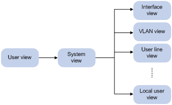
You are placed in user view immediately after you log in to the CLI. The user view prompt is <Device-name>, where Device-name indicates the device name. The device name is Sysname by default. You can change it by using the sysname command.
In user view, you can do the following:
· Perform basic operations including display, debug, file management, FTP, Telnet, clock setting, and reboot.
· Enter system view. The system view prompt is [Device-name].
In system view, you can do the following:
· Configure global settings (such as the daylight saving time, banners, and hotkeys) and some features.
· Enter different feature views. For example, you can enter interface view to configure interface parameters, enter VLAN view to add ports to the VLAN, and enter user line view to configure login user attributes.
A feature view might have child views.
To display all commands available in a view, enter a question mark (?) at the view prompt.
Entering system view from user view
|
Task |
Command |
|
Enter system view. |
system-view |
Returning to the upper-level view from any view
|
Task |
Command |
|
Return to the upper-level view from any view. |
quit |
Executing the quit command in user view terminates your connection to the device.
In public key view, use the peer-public-key end command to return to system view.
Returning to user view
To return directly to user view from any other view, use the return command or press Ctrl+Z.
|
Task |
Command |
|
Return directly to user view. |
return |
Accessing the CLI online help
The CLI online help is context sensitive. Enter a question mark at any prompt or in any position of a command to display all available options.
To access the CLI online help, use one of the following methods:
· Enter a question mark at a view prompt to display the first keyword of every command available in the view. For example:
<Sysname> ?
User view commands:
access-list acl
archive Archive configuration
backup Backup the startup configuration file to a TFTP server
blade
boot-loader Software image file management
…
· Enter a space and a question mark after a command keyword to display all available, subsequent keywords and arguments.
¡ If the question mark is in the place of a keyword, the CLI displays all possible keywords, each with a brief description. For example:
<Sysname> terminal ?
debugging Enable to display debugging logs on the current terminal
logging Display logs on the current terminal
monitor Enable to display logs on the current terminal
¡ If the question mark is in the place of an argument, the CLI displays the description of the argument. For example:
<Sysname> system-view
[Sysname] interface vlan-interface ?
<1-4094> Vlan-interface interface number
[Sysname] interface vlan-interface 1 ?
<cr>
[Sysname] interface vlan-interface 1
<1-4094> is the value range for the argument. <cr> indicates that the command is complete and you can press Enter to execute the command.
· Enter an incomplete keyword string followed by a question mark to display all keywords starting with that string. For example:
<Sysname> f?
fdisk
fixdisk
format
free
ftp
<Sysname> display ftp?
ftp
ftp-server
ftp-user
Using the undo form of a command
Most configuration commands have an undo form for the following:
· Canceling a configuration.
· Restoring the default.
· Disabling a feature.
For example, the info-center enable command enables the information center. The undo info-center enable command disables the information center.
Entering a command
When you enter a command, you can do the following:
· Use keys or hotkeys to edit the command line.
· Use abbreviated keywords or keyword aliases.
Editing a command line
To edit a command line, use the keys listed in Table 1 or the hotkeys listed in Table 3. When you are finished, you can press Enter to execute the command.
The total length of a command line cannot exceed 512 characters, including spaces and special characters.
Table 1 Command line editing keys
|
Keys |
Function |
|
Common keys |
If the edit buffer is not full, pressing a common key inserts a character at the position of the cursor and moves the cursor to the right. The edit buffer can store up to 511 characters. Unless the buffer is full, all common characters that you enter before pressing Enter are saved in the edit buffer. |
|
Backspace |
Deletes the character to the left of the cursor and moves the cursor back one character. |
|
Left arrow key (←) |
Moves the cursor one character to the left. |
|
Right arrow key (→) |
Moves the cursor one character to the right. |
|
Up arrow key (↑) |
Gets the previous history command. |
|
Down arrow key (↓) |
Gets the next history command. |
|
Tab |
If you press Tab after entering part of a keyword, the system automatically completes the keyword: · If a unique match is found, the system displays the complete keyword. · If there is more than one match, press Tab multiple times to pick the keyword you want to enter. · If there is no match, the system does not modify what you entered but displays it again in the next line. |
Entering a text or string type value for an argument
A text type argument value can contain printable characters other than the question mark (?).
A string type argument value can contain printable characters other than the following:
· Question mark (?).
· Quotation mark (").
· Backward slash (\).
· Space.
A specific argument might have more requirements. For more information, see the relevant command reference.
To enter a printable character, you can enter the character or its ASCII code (in the range of 32 to 126).
Abbreviating commands
You can enter a command line quickly by entering incomplete keywords that uniquely identify the complete command. In user view, for example, commands starting with an s include startup saved-configuration and system-view. To enter the command system-view, you only need to type sy. To enter the command startup saved-configuration, type st s.
You can also press Tab to complete an incomplete keyword.
Configuring and using command aliases
For example, if you configure the alias siprt for display ip routing-table, you can enter siprt to execute the display ip routing-table command. If you configure the alias ship for display ip, you can use ship to execute all commands starting with display ip:
· Enter ship routing-table to execute the display ip routing-table command.
· Enter ship interface to execute the display ip interface command.
Usage guidelines
After you successfully execute a command by using an alias, the system saves the command, instead of the alias, to the running configuration.
The command string represented by an alias can include up to nine parameters. Each parameter starts with the dollar sign ($) and a sequence number in the range of 1 to 9. For example, you can configure the alias shinc for the display $1 | include $2 command. Then, you can enter shinc hotkey CTRL_C to execute the display hotkey | include CTRL_C command.
To use an alias for a command that has parameters, you must specify a value for each parameter. If you fail to do so, the system displays a command incomplete error message and the command string represented by the alias.
The system defines a set of command aliases, as listed in Table 2.
Table 2 System-defined command aliases
|
Alias |
Command string |
|
access-list |
acl |
|
end |
return |
|
erase |
delete |
|
exit |
quit |
|
hostname |
sysname |
|
logging |
info-center |
|
no |
undo |
|
show |
display |
|
write |
save |
Configuration procedure
To configure a command alias:
|
Step |
Command |
Remarks |
|
1. Enter system view. |
system-view |
N/A |
|
2. Configure a command alias. |
alias alias command |
By default, the system defines the command aliases listed in Table 2. |
|
3. (Optional.) Display command aliases. |
display alias [ alias ] |
This command is available in any view. |
Configuring and using command hotkeys
The system defines the hotkeys shown in Table 3 and provides five configurable command hotkeys. Pressing a command hotkey is the same as entering a command.
If a hotkey is also defined by the terminal software you are using to interact with the device, the terminal software definition takes effect.
To configure a command hotkey:
|
Step |
Command |
Remarks |
|
4. Enter system view. |
system-view |
N/A |
|
5. Assign a command to a hotkey. |
hotkey { ctrl_g | ctrl_l | ctrl_o | ctrl_t | ctrl_u } command |
By default: · Ctrl+G is assigned the display current-configuration command. · Ctrl+L is assigned the display ip routing-table command. · Ctrl+O is assigned the undo debugging all command. · No command is assigned to Ctrl+T or Ctrl+U. |
|
6. (Optional.) Display hotkeys. |
display hotkey |
This command is available in any view. |
Table 3 System-reserved hotkeys
|
Hotkey |
Function |
|
Ctrl+A |
Moves the cursor to the beginning of a line. |
|
Ctrl+B |
Moves the cursor one character to the left. |
|
Ctrl+C |
Stops the current command. |
|
Ctrl+D |
Deletes the character at the cursor. |
|
Ctrl+E |
Moves the cursor to the end of a line. |
|
Ctrl+F |
Moves the cursor one character to the right. |
|
Ctrl+H |
Deletes the character to the left of the cursor. |
|
Ctrl+K |
Aborts the connection request. |
|
Ctrl+R |
Redisplays the current line. |
|
Ctrl+V |
Pastes text from the clipboard. |
|
Ctrl+W |
Deletes the word to the left of the cursor. |
|
Ctrl+X |
Deletes all characters to the left of the cursor. |
|
Ctrl+Y |
Deletes all characters to the right of the cursor. |
|
Ctrl+Z |
Returns to user view. |
|
Ctrl+] |
Terminates the current connection. |
|
Esc+B |
Moves the cursor back one word. |
|
Esc+D |
Deletes all characters from the cursor to the end of the word. |
|
Esc+F |
Moves the cursor forward one word. |
Enabling redisplaying entered-but-not-submitted commands
Your input might be interrupted by system information output. If redisplaying entered-but-not-submitted commands is enabled, the system redisplays your input after finishing the output. You can then continue entering the command line.
To enable redisplaying entered-but-not-submitted commands:
|
Step |
Command |
Remarks |
|
1. Enter system view. |
system-view |
N/A |
|
2. Enable redisplaying entered-but-not-submitted commands. |
info-center synchronous |
By default, the system does not redisplay entered-but-not-submitted commands. For more information about this command, see Network Management and Monitoring Command Reference. |
Understanding command-line error messages
After you press Enter to submit a command, the command line interpreter examines the command syntax.
· If the command passes syntax check, the CLI executes the command.
· If the command fails syntax check, the CLI displays an error message.
Table 4 Common command-line error messages
|
Error message |
Cause |
|
% Unrecognized command found at '^' position. |
The keyword in the marked position is invalid. |
|
% Incomplete command found at '^' position. |
One or more required keywords or arguments are missing. |
|
% Ambiguous command found at '^' position. |
The entered character sequence matches more than one command. |
|
% Too many parameters. |
The entered character sequence contains excessive keywords or arguments. |
|
% Wrong parameter found at '^' position. |
The argument in the marked position is invalid. |
Using the command history function
The system automatically saves commands successfully executed by a login user to two command history buffers:
· Command history buffer for the user line.
· Command history buffer for all user lines.
Table 5 Comparison between the two types of command history buffers
|
Item |
Command history buffer for a user line |
Command history buffer for all user lines |
|
What kind of commands are stored in the buffer? |
Commands successfully executed by the current user of the user line. |
Commands successfully executed by all login users. |
|
Cleared when the user logs out? |
Yes. |
No. |
|
How to view buffered commands? |
Use the display history-command command. |
Use the display history-command all command. |
|
How to call buffered commands? |
· In Windows 200x or Windows XP HyperTerminal or Telnet, use the up or down arrow key (↑ or ↓) to navigate to a command in the buffer and press Enter to execute the command again. · In Windows 9x HyperTerminal, use Ctrl+P and Ctrl+N to do so. |
You cannot call buffered commands. |
|
How to set the buffer size? |
Use the history-command max-size size-value command in user line view to set the buffer size. By default, the buffer can store up to 10 commands. |
You cannot set the buffer size. By default, the buffer can store up to 1024 commands. |
|
How to disable the buffer? |
Setting the buffer size to 0 disables the buffer. |
You cannot disable the buffer. |
The system follows these rules when buffering commands:
· Buffering a command in the exact format in which the command was entered. For example, if you enter an incomplete command, the buffered command is also incomplete. If you enter a command with a command keyword alias, the buffered command also uses the alias.
· If you enter a command in the same format multiple times in succession, the system buffers the command only once. If you enter a command in different formats multiple times, the system buffers each command format. For example, display cu and display current-configuration are buffered as two entries but successive repetitions of display cu create only one entry.
· To buffer a new command when a buffer is full, the system deletes the oldest command entry in the buffer.
Controlling the CLI output
This section describes the CLI output control features that help you identify the desired output.
Pausing between screens of output
The system automatically pauses after displaying a screen if the output is too long to fit on one screen. You can use the keys described in "Output controlling keys" to display more information or stop the display.
By default, up to 24 lines can be displayed on a screen. You can change the limit by using the screen-length screen-length command. For more information about this command, see Fundamentals Command Reference.
You can also disable pausing between screens of output for the current session. Then, all output is displayed at one time and the screen is refreshed continuously until the final screen is displayed.
Output controlling keys
|
Keys |
Function |
|
Space |
Displays the next screen. |
|
Enter |
Displays the next line. |
|
Ctrl+C |
Stops the display and cancels the command execution. |
|
<PageUp> |
Displays the previous page. |
|
<PageDown> |
Displays the next page. |
Disabling pausing between screens of output
To disable pausing between screens of output, execute the following command in user view:
|
Task |
Command |
Remarks |
|
Disable pausing between screens of output for the current session. |
screen-length disable |
The default for a session depends on the setting of the screen-length command in user line view. The default of the screen-length command is pausing between screens of output and displaying up to 24 lines on a screen. This command is a one-time command and takes effect only for the current session. |
Numbering each output line from a display command
You can use the | by-linenum option to prefix each display command output line with a number for easy identification.
Each line number is displayed as a 5-character string and might be followed by a colon (:) or hyphen (-). If you specify the | by-linenum option and the | begin regular-expression option for a display command, a hyphen is displayed for all lines that do not match the regular expression.
To number each output line from a display command:
|
Task |
Command |
|
Number each output line from a display command. |
display command | by-linenum |
For example:
# Display information about VLAN 999, numbering each output line.
<Sysname> display vlan 999 | by-linenum
1: VLAN ID: 999
2: VLAN type: Static
3: Route interface: Configured
4: IP address: 192.168.2.1
5: Subnet mask: 255.255.255.0
6: Description: For LAN Access
7: Name: VLAN 0999
8: Tagged ports: None
9: Untagged ports:
10: FortyGigE1/0/1
Filtering the output from a display command
You can use the | { begin | exclude | include } regular-expression option to filter the display command output:
· begin—Displays the first line matching the specified regular expression and all subsequent lines.
· exclude—Displays all lines not matching the specified regular expression.
· include—Displays all lines matching the specified regular expression.
· regular-expression—A case-sensitive string of 1 to 256 characters, which can contain the special characters described in Table 6.
The filtering operation takes time. The more complicated the regular expression is, the longer the filtering operation takes. To stop the operation, press Ctrl+C.
Table 6 Special characters supported in a regular expression
|
Characters |
Meaning |
Examples |
|
^ |
Matches the beginning of a line. |
"^u" matches all lines beginning with "u". A line beginning with "Au" is not matched. |
|
$ |
Matches the end of a line. |
"r$" matches all lines ending with "r". A line ending with "rA" is not matched. |
|
. (period) |
Matches any single character. |
".s" matches "as" and "bs". |
|
* |
Matches the preceding character or string zero, one, or multiple times. |
"zo*" matches "z" and "zoo", and "(zo)*" matches "zo" and "zozo". |
|
+ |
Matches the preceding character or string one or multiple times. |
"zo+" matches "zo" and "zoo", but not "z". |
|
| |
Matches the preceding or succeeding string. |
"def|int" matches a line containing "def" or "int". |
|
( ) |
Matches the string in the parentheses, usually used together with the plus sign (+) or asterisk sign (*). |
"(123A)" matches "123A". "408(12)+" matches "40812" and "408121212", but not "408". |
|
\N |
Matches the preceding strings in parentheses, with the Nth string repeated once. |
"(string)\1" matches a string containing "stringstring". "(string1)(string2)\2" matches a string containing "string1string2string2". "(string1)(string2)\1\2" matches a string containing " string1string2string1string2". |
|
[ ] |
Matches a single character in the brackets. |
"[16A]" matches a string containing 1, 6, or A; "[1-36A]" matches a string containing 1, 2, 3, 6, or A (- is a hyphen). To match the character "]", put it immediately after "[", for example, []abc]. There is no such limit on "[". |
|
[^] |
Matches a single character that is not in the brackets. |
"[^16A]" matches a string that contains at least one character other than 1, 6, or A, such as "abc". A match can also contain 1, 6, or A (such as "m16"), but it cannot contain these three characters only (such as 1, 16, or 16A). |
|
{n} |
Matches the preceding character n times. The number n must be a nonnegative integer. |
"o{2}" matches "food", but not "Bob". |
|
{n,} |
Matches the preceding character n times or more. The number n must be a nonnegative integer. |
"o{2,}" matches "foooood", but not "Bob". |
|
{n,m} |
Matches the preceding character n to m times or more. The numbers n and m must be nonnegative integers and n cannot be greater than m. |
" o{1,3}" matches "fod", "food", and "foooood", but not "fd". |
|
\< |
Matches a string that starts with the pattern following \<. A string that contains the pattern is also a match if the characters preceding the pattern are not digits, letters, or underscores. |
"\<do" matches "domain" and "doa". |
|
\> |
Matches a string that ends with the pattern preceding \>. A string that contains the pattern is also a match if the characters following the pattern are not digits, letters, or underscores. |
"do\>" matches "undo" and "cdo". |
|
\b |
Matches a word that starts with the pattern following \b or ends with the pattern preceding \b. |
"er\b" matches "never", but not "verb" or "erase". "\ber" matches "erase", but not "verb" or "never". |
|
\B |
Matches a word that contains the pattern but does not start or end with the pattern. |
"er\B" matches "verb", but not "never" or "erase". |
|
\w |
Same as [A-Za-z0-9_], matches a digit, letter, or underscore. |
"v\w" matches "vlan" and "service". |
|
\W |
Same as [^A-Za-z0-9_], matches a character that is not a digit, letter, or underscore. |
"\Wa" matches "-a", but not "2a" or "ba". |
|
\ |
Escape character. If a special character listed in this table follows \, the specific meaning of the character is removed. |
"\\" matches a string containing "\", "\^" matches a string containing "^", and "\\b" matches a string containing "\b". |
For example:
# Use | begin line in the display current-configuration command to match the first line of output that contains line to the last line of output.
<Sysname> display current-configuration | begin line
line class aux
user-role network-admin
#
line class vty
user-role network-operator
#
line aux 1
user-role network-admin
#
line vty 0 63
authentication-mode scheme
user-role network-operator
#
ssh server enable
#
return
# Use | exclude Direct in the display ip routing-table command to filter out direct routes and display only the non-direct routes.
<Sysname> display ip routing-table | exclude Direct
Destinations : 12 Routes : 12
Destination/Mask Proto Pre Cost NextHop Interface
2.2.2.0/24 OSPF 10 2 1.1.2.2 FGE1/0/2
# Use | include snmp in the display current-configuration command to filter in entries that contain snmp.
<Sysname> display current-configuration | include snmp
snmp-agent
snmp-agent community write private
snmp-agent community read public
snmp-agent sys-info version all
snmp-agent target-host trap address udp-domain 192.168.1.26 params securityname public
Saving the output from a display command to a file
A display command shows certain configuration and operation information of the device. Its output might vary over time or with user configuration or operation. You can save the output to a file for future retrieval or troubleshooting.
Use one of the following methods to save the output from a display command:
· Save the output to a separate file. Use this method if you want to use one file for a single display command.
· Append the output to the end of a file. Use this method if you want to use one file for multiple display commands.
To save the output from a display command to a file, use one of the following commands in any view:
|
Task |
Command |
|
Save the output from a display command to a separate file. |
display command > filename |
|
Append the output from a display command to the end of a file. |
display command >> filename |
For example:
# Save the VLAN 1 settings to a separate file named vlan.txt.
<Sysname> display vlan 1 > vlan.txt
# Verify whether the VLAN 1 settings are saved to file vlan.txt.
<Sysname> more vlan.txt
VLAN ID: 1
VLAN type: Static
Route interface: Not configured
Description: VLAN 0001
Name: VLAN 0001
Tagged ports: None
Untagged ports:
FortyGigE1/0/2
# Append the VLAN 999 settings to the end of file vlan.txt.
<Sysname> display vlan 999 >> vlan.txt
# Verify whether the VLAN 999 settings are appended to the end of file vlan.txt.
<Sysname> more vlan.txt
VLAN ID: 1
VLAN type: Static
Route interface: Not configured
Description: VLAN 0001
Name: VLAN 0001
Tagged ports: None
Untagged ports:
FortyGigE1/0/2
VLAN ID: 999
VLAN type: Static
Route interface: Configured
IP address: 192.168.2.1
Subnet mask: 255.255.255.0
Description: For LAN Access
Name: VLAN 0999
Tagged ports: None
Untagged ports:
FortyGigE1/0/1
Viewing and managing the output from a display command effectively
You can use the following measures in combination to filter and manage the output from a display command:
· Numbering each output line from a display command
· Filtering the output from a display command
· Saving the output from a display command to a file
To use multiple measures to view and manage the output from a display command effectively, execute the following command in any view:
|
Task |
Command |
|
View and manage the output from a display command effectively. |
display command [ | [ by-linenum ] { begin | exclude | include } regular-expression ] [ > filename | >> filename ] |
For example:
# Save the running configuration to a separate file named test.txt, with each line numbered.
<Sysname> display current-configuration | by-linenum > test.txt
# Append lines including "snmp" in the running configuration to the file test.txt.
<Sysname> display current-configuration | include snmp >> test.txt
# Display the first line that begins with "user-group" in the running configuration and all the following lines.
<Sysname> display current-configuration | by-linenum begin user-group
114: user-group system
115- #
116- return
Saving the running configuration
To make your configuration take effect after a reboot, save the running configuration to a configuration file by using the save command in any view. This command saves all commands that have been successfully executed, except for the one-time commands. Typical one-time commands include display commands used for displaying information and reset commands used for clearing information.
For more information about the save command, see Fundamentals Command Reference.
Login overview
The first time you access the device, you can log in to the CLI of the device through the console port. After login, you can change console login parameters, or configure other access methods, including Telnet, SSH, and SNMP.
The device supports the FIPS mode that complies with NIST FIPS 140-2 requirements. Support for features, commands, and parameters might differ in FIPS mode and non-FIPS mode. For more information about FIPS mode, see Security Configuration Guide.
Telnet login is not supported in FIPS mode.
Table 7 Login methods at a glance
|
Login method |
Default settings and minimum configuration requirements |
|
|
|
||
|
By default, login through the console port is enabled, no username or password is required, and the user role network-admin is assigned. After login, configure password or scheme authentication mode to improve device security. |
||
|
By default, Telnet login is disabled. To Log in through Telnet, complete the following configuration tasks: · Enable the Telnet server feature. · Assign an IP address to a Layer 3 interface and make sure the interface and the Telnet client can reach each other. · Configure an authentication mode for VTY login users. By default, password authentication is used but no password is configured. · Assign a user role to VTY login users (network-operator by default). |
||
|
By default, SSH login is disabled. To log in through SSH, complete the following configuration tasks: · Enable the SSH server feature and configure SSH attributes. · Assign an IP address to a Layer 3 interface and make sure the interface and the SSH client can reach each other. · Configure scheme authentication for VTY login users (password authentication by default). · Assign a user role to VTY login users (network-operator by default). |
||
|
By default, SNMP access is disabled. To access the device through SNMP, complete the following configuration tasks: · Assign an IP address to a Layer 3 interface, and make sure the interface and the NMS can reach each other. · Configure SNMP basic parameters. |
||
Logging in through the console port for the first device access
The first time you access the device, you can only log in to the CLI through the console port.
To log in through the console port:
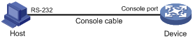
1. Connect the DB-9 female connector of the console cable to the serial port of the PC.
2. Connect the RJ-45 connector of the console cable to the console port of the device.
|
|
IMPORTANT: · Identify the mark on the console port and make sure you are connecting to the correct port. · The serial ports on PCs do not support hot swapping. If the switch has been powered on, always connect the console cable to the PC before connecting it to the switch, and always disconnect the console cable from the switch before disconnecting it from the PC. |
Figure 3 Connecting a terminal to the console port
3. If the PC is off, turn on the PC.
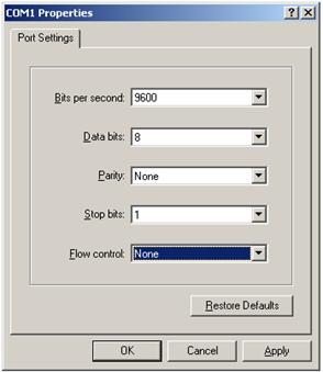
4. On the PC, launch the terminal emulation program and create a connection that uses the serial port connected to the device. Set the port properties so the port properties match the following console port default settings:
¡ Bits per second—9600 bps
¡ Flow control—None
¡ Parity—None
¡ Stop bits—1
¡ Data bits—8
Figure 4 through Figure 6 show the configuration procedure on Windows XP HyperTerminal. On Windows Server 2003, you must add the HyperTerminal program first. On Windows Server 2008, Windows 7, Windows Vista, or another operating system, you must obtain and install a third-party terminal control program and follow the user guide or online help to log in to the device.
To start the HyperTerminal on Windows XP:
a. Click start.
b. Select All Programs > Accessories > Communications > Hyper Terminal.
To view the serial port connected to the device:
c. Right-click the My Computer icon on the desktop.
d. Select Manage to open the Computer Management window.
e. Select System Tools > Device Manager from the navigation tree.
f. Select Ports (COM & LPT) from the right pane.
Figure 4 Creating a connection
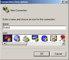
Figure 5 Specifying the serial port used to establish the connection
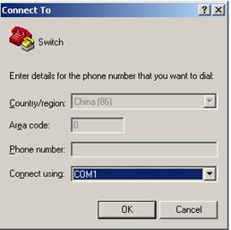
Figure 6 Setting the properties of the serial port
5. Power on the device and press Enter as prompted.
6. At the default user view prompt <H3C>, enter commands to configure the device or to view the running status of the device. To get help, enter ?.
Logging in to the CLI
By default, you can log in to the CLI through the console port. After you log in, you can configure other login methods, including Telnet, and SSH.
To prevent illegal access to the CLI and control user behavior, you can configure login authentication, assign user roles, configure command authorization and command accounting, and use ACLs to filter unauthorized logins.
This chapter describes how to configure and use CLI login methods, including login authentication, user roles, and common user line settings. For more information about command authorization, command accounting, and unauthorized access filtering, see "Controlling user access."
CLI overview
User lines
The device uses user lines (also called "user interfaces") to manage CLI sessions and monitor user behavior. You can configure access control settings, including login authentication and user role, on user lines. After users are logged in, their actions must be compliant with the settings on the user lines assigned to them.
Users are assigned different user lines, depending on their login methods, as shown in Table 8.
Table 8 CLI login method and user line matrix
|
User line |
Login method |
|
AUX line |
Console port. |
|
Virtual type terminal (VTY) line |
Telnet or SSH. |
User line assignment
The device automatically assigns user lines to CLI login users, depending on their login methods. Each user line can be assigned only to one user at a time. If no user line is available, a CLI login attempt will be rejected.
For a CLI login, the device always picks the lowest numbered user line from the idle user lines available for the login type. For example, four VTY lines (0 to 3) are configured, of which VTY 0 and VTY 3 are idle. When a user Telnets to the device, the device assigns VTY 0 to the user and uses the settings on VTY 0 to authenticate and manage the user.
User line identification
Every user line has an absolute number and a relative number for identification.
An absolute number uniquely identifies a user line among all user lines. The user lines are numbered starting from 0 and incrementing by 1 and in the sequence of AUX and VTY lines. You can use the display line command without any parameters to view supported user lines and their absolute numbers.
A relative number uniquely identifies a user line among all user lines that are the same type. The number format is user line type + number. Both the types of user lines are numbered starting from 0 and incrementing by 1. For example, the first VTY line is VTY 0.
Login authentication modes
You can configure login authentication to prevent illegal access to the device CLI.
In non-FIPS mode, the device supports the following login authentication modes:
· None—Disables authentication. This mode allows access without authentication and is insecure.
· Password—Requires password authentication.
· Scheme—Uses the AAA module to provide local or remote login authentication. You must provide a username and password at login.
In FIPS mode, the device supports only the scheme authentication mode.
Different login authentication modes require different user line configurations, as shown in Table 9.
Table 9 Configuration required for different login authentication modes
|
Authentication mode |
Configuration tasks |
|
|
None |
Set the authentication mode to none. |
|
|
Password |
3. Set the authentication mode to password. 4. Set a password. |
|
|
Scheme |
5. Set the authentication mode to scheme. 6. Configure login authentication methods in ISP domain view. For more information, see Security Configuration Guide. |
|
User roles
A user is assigned one or more user roles at login, and a user can access only commands permitted by the assigned user roles. For more information about user roles, see "Configuring RBAC."
The device assigns user roles based on the login authentication mode and login method:
· If none or password authentication is used, the device assigns user roles according to the user role configuration made on the user line.
· If scheme authentication is used:
¡ For an SSH login user who uses publickey or password-publickey authentication, the device assigns user roles according to the user role configuration made for the user in local user view.
¡ For other users, the device assigns user roles according to the user role configuration made on the AAA module. For remote AAA authentication users, if the AAA server does not assign any user role to a user and the default user role feature is disabled, the user cannot log in.
FIPS compliance
The device supports the FIPS mode that complies with NIST FIPS 140-2 requirements. Support for features, commands, and parameters might differ in FIPS mode and non-FIPS mode. For more information about FIPS mode, see Security Configuration Guide.
Telnet login is not supported in FIPS mode.
Logging in through the console port locally
You can connect a terminal to the console port of the device to log in and manage the device, as shown in Figure 7. For the login procedure, see "Logging in through the console port for the first device access."
Figure 7 Logging in through the console port
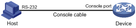
By default, console login is enabled and does not require authentication. To improve device security, configure the password or scheme authentication mode and assign user roles immediately after you log in to the device for the first time.
To configure console login, complete the following tasks:
|
Task |
Remarks |
|
(Required.) Configuring login authentication: · Disabling authentication for console login |
Configure one authentication mode as required. In FIPS mode, only the scheme authentication mode is supported. |
|
(Optional.) Configuring common AUX line settings |
N/A |
The console login configuration is effective only for users who log in after the configuration is completed.
Disabling authentication for console login
|
Step |
Command |
Remarks |
|
1. Enter system view. |
system-view |
N/A |
|
2. Enter AUX line view or class view. |
·
To enter AUX line view: ·
To enter AUX line class view: |
Use either command. A setting in user line view is applied only to the user line. A setting in user line class view is applied to all user lines of the class. A non-default setting in either view takes precedence over a default setting in the other view. A non-default setting in user line view takes precedence over a non-default setting in user line class view. A setting in user line view takes effect immediately and affects the online user. A setting in user line class view does not affect online users and takes effect only for users who log in after the configuration is completed. |
|
3. Disable authentication. |
authentication-mode none |
By default, authentication is disabled for the AUX line. |
|
4. Assign a user role. |
user-role role-name |
By default, an AUX line user is assigned the user role network-admin. |
The next time you attempt to log in through the console port, you do not need to provide any username or password.
Configuring password authentication for console login
|
Step |
Command |
Remarks |
|
1. Enter system view. |
system-view |
N/A |
|
2. Enter AUX line view or class view. |
·
To enter AUX line view: ·
To enter AUX line class view: |
Use either command. A setting in user line view is applied only to the user line. A setting in user line class view is applied to all user lines of the class. A non-default setting in either view takes precedence over a default setting in the other view. A non-default setting in user line view takes precedence over a non-default setting in user line class view. A setting in user line view takes effect immediately and affects the online user. A setting in user line class view does not affect online users and takes effect only for users who log in after the configuration is completed. |
|
3. Enable password authentication. |
authentication-mode password |
By default, authentication is disabled for the AUX line. |
|
4. Set a password. |
set authentication password { hash | simple } password |
By default, no password is set. |
|
5. Assign a user role. |
user-role role-name |
By default, an AUX line user is assigned the user role network-admin. |
The next time you attempt to log in through the console port, you must provide the configured login password.
Configuring scheme authentication for console login
|
Step |
Command |
Remarks |
|
1. Enter system view. |
system-view |
N/A |
|
2. Enter AUX line view or class view. |
·
To enter AUX line view: ·
To enter AUX line class view: |
Use either command. A setting in user line view is applied only to the user line. A setting in user line class view is applied to all user lines of the class. A non-default setting in either view takes precedence over a default setting in the other view. A non-default setting in user line view takes precedence over a non-default setting in user line class view. A setting in user line view takes effect immediately and affects the online user. A setting in user line class view does not affect online users and takes effect only for users who log in after the configuration is completed. |
|
3. Enable scheme authentication. |
authentication-mode scheme |
By default, authentication is disabled for the AUX line. |
To use scheme authentication, you must also configure login authentication methods in ISP domain view:
· To use local authentication, you must create a local user and configure local user attributes on the device.
· To use remote authentication, you must configure a scheme on the device and configure the remote server.
For more information, see Security Configuration Guide.
The next time you attempt to log in through the console port, you must provide the configured login username and password.
Configuring common AUX line settings
Some common settings configured for an AUX line take effect immediately and can interrupt the current session. Use a login method different from console login to log in to the device before you change AUX line settings.
To log in through the console port after the configuration is completed, change the terminal settings on the configuration terminal to match the console port settings on the device.
To configure common settings for an AUX line:
|
Step |
Command |
|
|
N/A |
||
|
2. Enter AUX line view or class view. |
·
To enter AUX line view: ·
To enter AUX line class view: |
Use either command. A setting in user line view is applied only to the user line. A setting in user line class view is applied to all user lines of the class. A non-default setting in either view takes precedence over a default setting in the other view. A non-default setting in user line view takes precedence over a non-default setting in user line class view. A setting in user line view takes effect immediately and affects the online user. A setting in user line class view does not affect online users and takes effect only for users who log in after the configuration is completed. |
|
3. Set the baud rate. |
speed speed-value |
By default, the baud rate is 9600 bps. This command is not available in AUX line class view. |
|
4. Specify the parity check mode. |
parity { even | mark | none | odd | space } |
By default, the parity check mode is none, and no parity check is performed. This command is not available in AUX line class view. |
|
5. Specify the number of stop bits. |
stopbits { 1 | 1.5 | 2 } |
The default is 1. Stop bits indicate the end of a character. The more the stop bits, the slower the transmission. This command is not available in AUX line class view. |
|
6. Specify the number of data bits for each character. |
databits { 5 | 6 | 7 | 8 } |
The default is 8. The setting depends on the character coding type. For example, you can set it to 7 if standard ASCII characters are to be sent, and set it to 8 if extended ASCII characters are to be sent. This command is not available in AUX line class view. |
|
7. Define a shortcut key for starting a terminal session. |
activation-key character |
|
|
8. Define a shortcut key for terminating tasks. |
escape-key { character | default } |
|
|
9. Configure the flow control mode. |
flow-control { hardware | none | software } |
By default, the flow control mode is none. This command is not available in AUX line class view. |
|
10. Specify the terminal display type. |
terminal type { ansi | vt100 } |
By default, the terminal display type is ANSI. The device supports two terminal display types: ANSI and VT100. As a best practice, set the display type to VT100 on both the device and the configuration terminal. If either side uses the ANSI type, a display problem such as cursor positioning error might occur when a command line has more than 80 characters. |
|
11. Set the maximum number of lines to be displayed on a screen. |
screen-length screen-length |
By default, a screen displays 24 lines at most. |
|
12. Set the size of the command history buffer. |
history-command max-size value |
|
|
13. Set the CLI connection idle-timeout timer. |
idle-timeout minutes [ seconds ] |
By default, the CLI connection idle-timeout timer is 10 minutes. If no interaction occurs between the device and the user within the idle-timeout interval, the system automatically terminates the user connection on the user line. If you set the timeout timer to 0, the connection will not be aged out. |
Logging in through Telnet
You can Telnet to the device to remotely manage the device, or use the device as a Telnet client to Telnet to other devices to manage them.
By default, Telnet login is disabled on the device. To log in to the device through Telnet, you must first log in to the device through any other method, enable the Telnet server, and configure Telnet login authentication on the device.
|
|
NOTE: Telnet login is not supported in FIPS mode. For more information about FIPS mode, see Security Configuration Guide. |
Configuring Telnet login on the device
|
Task |
Remarks |
|
(Required.) Configuring login authentication: · Disabling authentication for Telnet login |
Configure one authentication mode as required. |
|
(Optional.) Setting the maximum number of concurrent Telnet users |
N/A |
|
(Optional.) Setting the DSCP value for outgoing Telnet packets |
N/A |
|
(Optional.) Configuring common VTY line settings |
N/A |
The Telnet login configuration is effective only for users who log in after the configuration is completed.
Disabling authentication for Telnet login
|
Step |
Command |
Remarks |
|
1. Enter system view. |
system-view |
N/A |
|
2. Enable Telnet server. |
telnet server enable |
By default, the Telnet server feature is disabled. |
|
3. Enter VTY line view or class view. |
·
To enter VTY line view: ·
To enter VTY line class view: |
Use either command. A setting in user line view is applied only to the user line. A setting in user line class view is applied to all user lines of the class. A non-default setting in either view takes precedence over a default setting in the other view. A non-default setting in user line view takes precedence over a non-default setting in user line class view. A setting in user line view takes effect immediately and affects the online user. A setting in user line class view does not affect online users and takes effect only for users who log in after the configuration is completed. |
|
4. Disable authentication. |
authentication-mode none |
By default, password authentication is enabled for VTY lines. In VTY line view, this command is associated with the protocol inbound command. If you specify a non-default value for only one of the two commands in VTY line view, the other command uses the default setting, regardless of the setting in VTY line class view. |
|
5. (Optional.) Assign a user role. |
user-role role-name |
By default, a VTY line user is assigned the user role network-operator. |
The next time you attempt to Telnet to the device, you do not need to provide any username or password, as shown in Figure 8. If the maximum number of login users has been reached, your login attempt fails and the message "All user lines are used, please try later!" appears.
Figure 8 Telnetting to the device without authentication

Configuring password authentication for Telnet login
|
Step |
Command |
Remarks |
|
1. Enter system view. |
system-view |
N/A |
|
2. Enable Telnet server. |
telnet server enable |
By default, the Telnet server feature is disabled. |
|
3. Enter VTY line view or class view. |
·
To enter VTY line view: ·
To enter VTY line class view: |
Use either command. A setting in user line view is applied only to the user line. A setting in user line class view is applied to all user lines of the class. A non-default setting in either view takes precedence over a default setting in the other view. A non-default setting in user line view takes precedence over a non-default setting in user line class view. A setting in user line view takes effect immediately and affects the online user. A setting in user line class view does not affect online users and takes effect only for users who log in after the configuration is completed. |
|
4. Enable password authentication. |
authentication-mode password |
By default, password authentication is enabled for VTY lines. In VTY line view, this command is associated with the protocol inbound command. If you specify a non-default value for only one of the two commands in VTY line view, the other command uses the default setting, regardless of the setting in VTY line class view. |
|
5. Set a password. |
set authentication password { hash | simple } password |
By default, no password is set. |
|
6. (Optional.) Assign a user role. |
user-role role-name |
By default, a VTY line user is assigned the user role network-operator. |
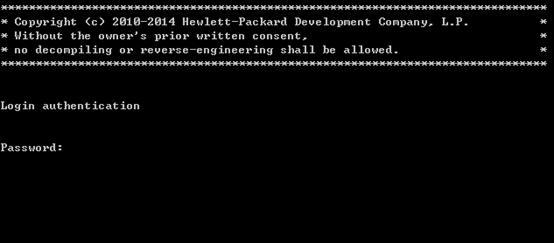
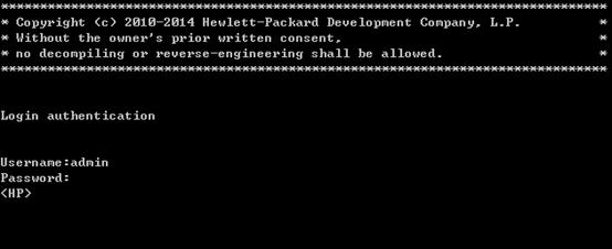
The next time you attempt to Telnet to the device, you must provide the configured login password, as shown in Figure 9. If the maximum number of login users has been reached, your login attempt fails and the message "All user lines are used, please try later!" appears.
Figure 9 Password authentication interface for Telnet login
Configuring scheme authentication for Telnet login
|
Step |
Command |
Remarks |
|
1. Enter system view. |
system-view |
N/A |
|
2. Enable Telnet server. |
telnet server enable |
By default, the Telnet server feature is disabled. |
|
3. Enter VTY line view or class view. |
·
To enter VTY line view: ·
To enter VTY line class view: |
Use either command. A setting in user line view is applied only to the user line. A setting in user line class view is applied to all user lines of the class. A non-default setting in either view takes precedence over a default setting in the other view. A non-default setting in user line view takes precedence over a non-default setting in user line class view. A setting in user line view takes effect immediately and affects the online user. A setting in user line class view does not affect online users and takes effect only for users who log in after the configuration is completed. |
|
4. Enable scheme authentication. |
authentication-mode scheme |
By default, password authentication is enabled for VTY lines. In VTY line view, this command is associated with the protocol inbound command. If you specify a non-default value for only one of the two commands in VTY line view, the other command uses the default setting, regardless of the setting in VTY line class view. |
To use scheme authentication, you must also configure login authentication methods in ISP domain view. For more information, see Security Configuration Guide.
The next time you attempt to Telnet to the CLI, you must provide the configured login username and password, as shown in Figure 10. If the maximum number of login users has been reached, your login attempt fails and the message "All lines are used, please try later!" appears.
Figure 10 Scheme authentication interface for Telnet login
Setting the maximum number of concurrent Telnet users
|
Step |
Command |
Remarks |
|
1. Enter system view. |
system-view |
N/A |
|
2. Set the maximum number of concurrent Telnet users. |
aaa session-limit telnet max-sessions |
By default, the maximum number of concurrent Telnet users is 32. Changing this setting does not affect online users. If the current number of online Telnet users is equal to or greater than the new setting, no additional Telnet users can log in until online users log out. For more information about this command, see Security Command Reference. |
Setting the DSCP value for outgoing Telnet packets
The DSCP value is carried in the ToS/Traffic class field of an IP packet, and it indicates the transmission priority of the packet.
To set the DSCP value for outgoing Telnet packets:
|
Step |
Command |
Remarks |
|
1. Enter system view. |
system-view |
N/A |
|
2. Set the DSCP value for outgoing Telnet packets. |
telnet server dscp dscp-value |
By default, the DSCP value is 48. |
Configuring common VTY line settings
For a VTY line, you can specify a command that is to be automatically executed when a user logs in. After executing the specified command and performing the incurred task, the system automatically disconnects the Telnet session. Typically, you configure the auto-execute command telnet X.X.X.X command on the device so the device redirects a Telnet user to the host at X.X.X.X. In this case, the connection to the current device is closed when the user terminates the Telnet connection to X.X.X.X.
To configure common settings for VTY lines:
|
Step |
Command |
Remarks |
|
1. Enter system view. |
system-view |
N/A |
|
2. Enter VTY line view or class view. |
·
To enter VTY line view: ·
To enter VTY line class view: |
Use either command. A setting in user line view is applied only to the user line. A setting in user line class view is applied to all user lines of the class. A non-default setting in either view takes precedence over a default setting in the other view. A non-default setting in user line view takes precedence over a non-default setting in user line class view. A setting in user line view takes effect immediately and affects the online user. A setting in user line class view does not affect online users and takes effect only for users who log in after the configuration is completed. |
|
3. Enable the terminal service. |
shell |
By default, terminal service is enabled. |
|
4. Specify the protocols for the user lines to support. |
protocol inbound { all | ssh | telnet } |
By default, both Telnet and SSH are supported. This configuration is effective only for users who log in to the user lines after the configuration is completed. In VTY line view, this command is associated with the authentication-mode command. If you specify a non-default value for only one of the two commands in VTY line view, the other command uses the default setting, regardless of the setting in VTY line class view. |
|
5. Define a shortcut key for terminating tasks. |
escape-key { character | default } |
By default, pressing Ctrl+C terminates a task. |
|
6. Specify the terminal display type. |
terminal type { ansi | vt100 } |
By default, the terminal display type is ANSI. |
|
7. Set the maximum number of lines to be displayed on a screen. |
screen-length screen-length |
By default, up to 24 lines is displayed on a screen. To disable pausing between screens of output, set the value to 0. |
|
8. Set the size of command history buffer. |
history-command max-size value |
By default, the buffer saves 10 history commands. |
|
9. Set the CLI connection idle-timeout timer. |
idle-timeout minutes [ seconds ] |
By default, the CLI connection idle-timeout timer is 10 minutes. If no interaction occurs between the device and the user within the idle-timeout interval, the system automatically terminates the user connection on the user line. If you set the timeout timer to 0, the connection will not be aged out. |
|
10. Specify the command to be automatically executed for login users on the user lines. |
auto-execute command command |
By default, no automatically executed command is specified.
Before you configure this command and save the configuration, make sure you can access the CLI through a different user line. |
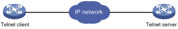
Using the device to log in to a Telnet server
You can use the device as a Telnet client to log in to a Telnet server. If the server is located in a different subnet than the device, make sure the two devices have routes to reach each other.
Figure 11 Telnetting from the device to a Telnet server
To use the device to log in to a Telnet server:
|
Step |
Command |
Remarks |
|
1. Enter system view. |
system-view |
N/A |
|
2. (Optional.) Specify the source IPv4 address or source interface for outgoing Telnet packets. |
telnet client source { interface interface-type interface-number | ip ip-address } |
By default, no source IPv4 address or source interface is specified, and the primary IPv4 address of the outbound interface is used as the source address for outgoing Telnet packets. |
|
3. Exit to user view. |
quit |
N/A |
|
4. Use the device to log in to a Telnet server. |
telnet remote-host [ service-port ] [ vpn-instance vpn-instance-name ] [ source { interface interface-type interface-number | ip ip-address } ] [ dscp dscp-value ] |
This command is available in user view. |
Logging in through SSH
SSH offers a secure method to remote login. By providing encryption and strong authentication, it protects devices against attacks such as IP spoofing and plain text password interception. For more information, see Security Configuration Guide.
You can use an SSH client to log in to the device for remote management, or use the device as an SSH client to log in to an SSH server.
By default, SSH login is disabled on the device. To log in to the device through SSH, you must log in to the device through any other method and configure SSH login on the device first.
Configuring SSH login on the device
This section provides the configuration procedure for when the SSH client authentication method is password. For more information about SSH and publickey authentication configuration, see Security Configuration Guide.
To configure SSH login on the device:
|
Step |
Command |
Remarks |
|
|
1. Enter system view. |
system-view |
N/A |
|
|
2. Create local key pairs. |
public-key local create { dsa | rsa | ecdsa } [ name key-name ] |
By default, no local key pairs are created. |
|
|
3. Enable SSH server. |
ssh server enable |
By default, SSH server is disabled. |
|
|
4. (Optional.) Create an SSH user and specify the authentication mode. |
·
In non-FIPS mode: ·
In FIPS mode: |
By default, no SSH user is configured on the device. |
|
|
5. Enter VTY line view or class view. |
·
To enter VTY line view: ·
To enter VTY line class view: |
Use either command. A setting in user line view is applied only to the user line. A setting in user line class view is applied to all user lines of the class. A non-default setting in either view takes precedence over a default setting in the other view. A non-default setting in user line view takes precedence over a non-default setting in user line class view. A setting in user line view takes effect immediately and affects the online user. A setting in user line class view does not affect online users and takes effect only for users who log in after the configuration is completed. |
|
|
6. Enable scheme authentication. |
authentication-mode scheme |
In non-FIPS mode, password authentication is enabled for VTY lines by default. In FIPS mode, scheme authentication is enabled for VTY lines by default. In VTY line view, this command is associated with the protocol inbound command. If you specify a non-default value for only one of the two commands in VTY line view, the other command uses the default setting, regardless of the setting in VTY line class view. |
|
|
7. (Optional.) Specify the protocols for the user lines to support. |
·
In non-FIPS mode: ·
In FIPS mode: |
In non-FIPS mode, both Telnet and SSH are supported by default. In FIPS mode, SSH is supported by default. This configuration takes effect only for users who log in to the user lines after the configuration is completed. In VTY line view, this command is associated with the authentication-mode command. If you specify a non-default value for only one of the two commands in VTY line view, the other command uses the default setting, regardless of the setting in VTY line class view. |
|
|
8. Set the maximum number of concurrent SSH users. |
aaa session-limit ssh max-sessions |
By default, the maximum number of concurrent SSH users is 32. Changing this setting does not affect online users. If the current number of online SSH users is equal to or greater than the new setting, no additional SSH users can log in until the online users log out. For more information about this command, see Security Command Reference. |
|
|
9. Exit to system view. |
quit |
N/A |
|
|
10. (Optional.) Configure common settings for VTY lines. |
N/A |
|
|
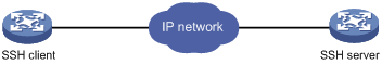
Using the device to log in to an SSH server
You can use the device as an SSH client to log in to an SSH server. If the server is located in a different subnet than the device, make sure the two devices have routes to reach each other.
Figure 12 Logging in to an SSH client from the device
Perform the following tasks in user view:
|
Task |
Command |
|
Log in to an IPv4 SSH server. |
ssh2 server |
To work with the SSH server, you might need to configure the SSH client. For information about configuring the SSH client, see Security Configuration Guide.
Displaying and maintaining CLI login
Execute display commands in any view and the other commands in user view.
|
Task |
Command |
Remarks |
|
Display online CLI user information. |
display users [ all ] |
N/A |
|
Display user line information. |
display line [ num1 | { aux | vty } num2 ] [ summary ] |
N/A |
|
Display the source IPv4 address or interface configured for the device to use for outgoing Telnet packets when serving as a Telnet client. |
display telnet client |
N/A |
|
Release a user line. |
free line { num1 | { aux | vty } num2 } |
Multiple users can log in to the device to simultaneously configure the device. When necessary, you can execute this command to release some connections. You cannot use this command to release the connection you are using. |
|
Lock the current user line. |
lock |
By default, the system does not lock any user line. This command is not supported in FIPS mode. |
|
Send messages to user lines. |
send { all | num1 | { aux | vty } num2 } |
This command is available in user view. |
Accessing the device through SNMP
You can run SNMP on an NMS to access the device MIB and perform Get and Set operations to manage and monitor the device.
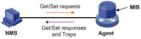
The device supports SNMPv1, SNMPv2c, and SNMPv3, and can work with various network management software products, including IMC. However, the device and the NMS must use the same SNMP version. For more information about SNMP, see Network Management and Monitoring Configuration Guide.
By default, SNMP access is disabled. To access the device through SNMP, you must log in to the device through any other method and configure SNMP access.
Configuring SNMPv3 access
|
Step |
Command |
Remarks |
|
1. Enter system view. |
system-view |
N/A |
|
2. Enable the SNMP agent. |
snmp-agent |
By default, the SNMP agent is disabled. |
|
3. (Optional.) Create or update MIB view information. |
snmp-agent mib-view { excluded | included } view-name oid-tree [ mask mask-value ] |
By default, the device has four views, all of which are named ViewDefault: · View 1 includes MIB subtree iso. · View 2 does not include subtree snmpUsmMIB. · View 3 does not include subtree snmpVacmMIB. · View 4 does not include subtree snmpModules.18. |
|
4. Create an SNMPv3 group. |
snmp-agent group v3 group-name [ authentication | privacy ] [ read-view view-name ] [ write-view view-name ] [ notify-view view-name ] [ acl acl-number ] * |
By default, no SNMPv3 group exists. |
|
5. Create an SNMPv3 user. |
snmp-agent usm-user v3 user-name group-name [ remote ip-address [ vpn-instance vpn-instance-name ] ] [ { cipher | simple } authentication-mode { md5 | sha } auth-password [ privacy-mode { aes128 | des56 } priv-password ] ] [ acl acl-number ] * |
To send informs to an SNMPv3 NMS, you must use the remote ip-address option to specify the IP address of the NMS. |
Configuring SNMPv1 or SNMPv2c access
|
Step |
Command |
Remarks |
|
1. Enter system view. |
system-view |
N/A |
|
2. Enable the SNMP agent. |
snmp-agent |
By default, the SNMP agent is disabled. |
|
3. (Optional.) Create or update MIB view information. |
snmp-agent mib-view { excluded | included } view-name oid-tree [ mask mask-value ] |
By default, the device has four views, all of which are named ViewDefault: · View 1 includes MIB subtree iso. · View 2 does not include subtree snmpUsmMIB. · View 3 does not include subtree snmpVacmMIB. · View 4 does not include subtree snmpModules.18. |
|
4. Configure the SNMP access right. |
·
(Method 1) Specify the SNMP NMS access right directly by configuring an
SNMP community: · (Method 2) Configure an SNMP group and add a user to the SNMP group: a. snmp-agent group { v1 | v2c } group-name [ read-view view-name ] [ write-view view-name ] [ notify-view view-name ] [ acl acl-number ] * b. snmp-agent usm-user { v1 | v2c } user-name group-name [ acl acl-number ] * |
Use either method. The username in method 2 is equivalent to the community name used in method 1, and must be the same as the community name configured on the NMS. By default, no SNMP group or SNMP community exists. |
Controlling user access
Use ACLs to prevent unauthorized access and configure command authorization and accounting to monitor and control user behavior. For more information about ACLs, see ACL and QoS Configuration Guide.
FIPS compliance
The device supports the FIPS mode that complies with NIST FIPS 140-2 requirements. Support for features, commands, and parameters might differ in FIPS mode and non-FIPS mode. For more information about FIPS mode, see Security Configuration Guide.
Telnet and HTTP are not supported in FIPS mode.
Controlling Telnet/SSH logins
Use basic ACLs (2000 to 2999) to filter Telnet and SSH logins by source IP address. Use advanced ACLs (3000 to 3999) to filter Telnet and SSH logins by source and/or destination IP address. Use Ethernet frame header ACLs (4000 to 4999) to filter Telnet and SSH logins by source MAC address.
If an applied ACL does not exist or has no rules, no user login restriction is applied. If the ACL exists and has rules, only users permitted by the ACL can access the device through Telnet or SSH.
Configuration procedures
|
Step |
Command |
Remarks |
|
1. Enter system view. |
system-view |
N/A |
|
Apply an ACL to filter Telnet logins. |
telnet server acl acl-number |
By default, no ACL is used to filter Telnet logins. |
To control SSH logins:
|
Step |
Command |
Remarks |
|
1. Enter system view. |
system-view |
N/A |
|
Apply an ACL to filter SSH logins. |
ssh server acl acl-number |
By default, no ACL is used to filter SSH logins. For more information, see Security Command Reference. |
Configuration example
Network requirements
Configure the device in Figure 14 to permit only Telnet packets sourced from Host A and Host B.
Configuration procedure
# Configure an ACL to permit packets sourced from Host A and Host B.
<Sysname> system-view
[Sysname] acl number 2000 match-order config
[Sysname-acl-basic-2000] rule 1 permit source 10.110.100.52 0
[Sysname-acl-basic-2000] rule 2 permit source 10.110.100.46 0
[Sysname-acl-basic-2000] quit
# Apply the ACL to filter Telnet logins.
[Sysname] telnet server acl 2000
Controlling SNMP access
Use a basic ACL (2000 to 2999) to control SNMP access by source IP address. To access the requested MIB view, an NMS must use a source IP address permitted by the ACL.
Configuration procedure
To control SNMP access, configure ACLs as required and complete the following configuration:
|
Step |
Command |
Remarks |
|
1. Enter system view. |
system-view |
N/A |
|
2. Apply the ACL to an SNMP community, group, or user. |
·
SNMP community: ·
SNMPv1/v2c group: ·
SNMPv3 group: ·
SNMPv1/v2c
user: ·
SNMPv3 user: |
For more information about SNMP, see Network Management and Monitoring Configuration Guide. |
Configuration example
Network requirements
Configure the device in Figure 15 to allow Host A and Host B to access the device through SNMP.

Configuration procedure
# Create an ACL to permit packets sourced from Host A and Host B.
<Sysname> system-view
[Sysname] acl number 2000 match-order config
[Sysname-acl-basic-2000] rule 1 permit source 10.110.100.52 0
[Sysname-acl-basic-2000] rule 2 permit source 10.110.100.46 0
[Sysname-acl-basic-2000] quit
# Associate the ACL with the SNMP community and the SNMP group.
[Sysname] snmp-agent community read aaa acl 2000
[Sysname] snmp-agent group v2c groupa acl 2000
[Sysname] snmp-agent usm-user v2c usera groupa acl 2000
Configuring command authorization
By default, commands are available for a user depending only on that user's user roles. When the authentication mode is scheme, you can configure the command authorization feature to further control access to commands.
After you enable command authorization, a command is available for a user only if the user has the commensurate user role and is authorized to use the command by the AAA scheme.
This section provides the procedure for configuring command authorization. To make the command authorization feature take effect, you must configure a command authorization method in ISP domain view. For more information, see Security Configuration Guide.
Configuration procedure
To configure command authorization:
|
Step |
Command |
Remarks |
|
1. Enter system view. |
system-view |
N/A |
|
2. Enter user line view or user line class view. |
·
To enter user line view: ·
To enter user line class view: |
Use either command. A setting in user line view is applied only to the user line. A setting in user line class view is applied to all user lines of the class. A non-default setting in either view takes precedence over a default setting in the other view. A non-default setting in user line view takes precedence over a non-default setting in user line class view. A setting in user line view takes effect immediately and affects the online user. A setting in user line class view does not affect online users and takes effect only for users who log in after the configuration is completed. |
|
3. Enable scheme authentication. |
authentication-mode scheme |
By default, authentication is disabled for the AUX line and password authentication is enabled for the VTY line. In VTY line view, this command is associated with the protocol inbound command. If you specify a non-default value for only one of the two commands in VTY line view, the other command uses the default setting, regardless of the setting in VTY line class view. |
|
4. Enable command authorization. |
command authorization |
By default, command authorization is disabled. The commands available for a user only depend on the user role. If the command authorization command is configured in user line class view, command authorization is enabled on all user lines in the class, and you cannot configure the undo command authorization command in the view of a user line in the class. |
Configuration example
Network requirements
As shown in Figure 16, Host A needs to log in to the device to manage the device.
Configure the device to perform the following operations:
· Allow Host A to Telnet in after authentication.
· Use the HWTACACS server to control the commands that the user can execute.
· If the HWTACACS server is not available, use local authorization.
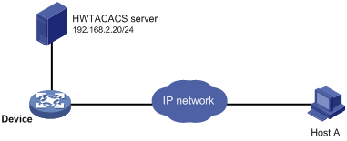
Configuration procedure
# Assign IP addresses to relevant interfaces and make sure the device and the HWTACACS server can reach each other and the device and Host A can reach each other. (Details not shown.)
# Enable the Telnet server.
<Device> system-view
[Device] telnet server enable
# Enable scheme authentication for user lines VTY 0 through VTY 63.
[Device] line vty 0 63
[Device-line-vty0-63] authentication-mode scheme
# Enable command authorization for the user lines.
[Device-line-vty0-63] command authorization
[Device-line-vty0-63] quit
# Configure an HWTACACS scheme that does the following:
· Uses the HWTACACS server at 192.168.2.20:49 for authentication and authorization. In this example, the HWTACACS server provides authentication and authorization services at port 49.
· Uses the shared key expert.
· Removes domain names from usernames sent to the HWTACACS server.
[Device] hwtacacs scheme tac
[Device-hwtacacs-tac] primary authentication 192.168.2.20 49
[Device-hwtacacs-tac] primary authorization 192.168.2.20 49
[Device-hwtacacs-tac] key authentication expert
[Device-hwtacacs-tac] key authorization expert
[Device-hwtacacs-tac] server-type standard
[Device-hwtacacs-tac] user-name-format without-domain
[Device-hwtacacs-tac] quit
# Configure the system-predefined domain system to use the HWTACACS scheme tac for login user authentication and command authorization and to use local authentication and local authorization as the backup method.
[Device] domain system
[Device-isp-system] authentication login hwtacacs-scheme tac local
[Device-isp-system] authorization command hwtacacs-scheme tac local
[Device-isp-system] quit
# Create local user monitor, set the password to 123, assign the Telnet service, and set the default user role to level-1.
[Device] local-user monitor
[Device-luser-manage-admin] password cipher 123
[Device-luser-manage-admin] service-type telnet
[Device-luser-manage-admin] authorization-attribute user-role level-1
Configuring command accounting
Command accounting allows the HWTACACS server to record all executed commands that are supported by the device, regardless of the command execution result. This feature helps control and monitor user behavior on the device.
When command accounting is disabled, the accounting server does not record the commands executed by users. If command accounting is enabled but command authorization is not, every executed command is recorded on the HWTACACS server. If both command accounting and command authorization are enabled, only authorized commands that are executed are recorded on the HWTACACS server.
This section provides only the procedure for configuring command accounting. To make the command accounting feature take effect, you must configure a command accounting method in ISP domain view. For more information, see Security Configuration Guide.
Configuration procedure
To configure command accounting:
|
Step |
Command |
Remarks |
|
1. Enter system view. |
system-view |
N/A |
|
2. Enter user line view or user line class view. |
·
To enter user line view: ·
To enter user line class view: |
Use either command. A setting in user line view is applied only to the user line. A setting in user line class view is applied to all user lines of the class. A non-default setting in either view takes precedence over a default setting in the other view. A non-default setting in user line view takes precedence over a non-default setting in user line class view. A setting in user line view takes effect immediately and affects the online user. A setting in user line class view does not affect online users and takes effect only for users who log in after the configuration is completed. |
|
3. Enable scheme authentication. |
authentication-mode scheme |
By default, authentication is disabled for the AUX line and password authentication is enabled for the VTY line. In VTY line view, this command is associated with the protocol inbound command. If you specify a non-default value for only one of the two commands in VTY line view, the other command uses the default setting, regardless of the setting in VTY line class view. |
|
4. Enable command accounting. |
command accounting |
By default, command accounting is disabled. The accounting server does not record the commands executed by users. If the command accounting command is configured in user line class view, command accounting is enabled on all user lines in the class. You cannot configure the undo command accounting command in the view of a user line in the class. |
Configuration example
Network requirements
As shown in Figure 17, users need to log in to the device to manage the device.
Configure the device to send commands executed by users to the HWTACACS server to monitor and control user operations on the device.
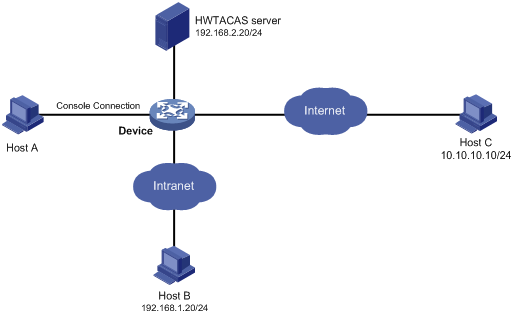
Configuration procedure
# Enable the Telnet server.
<Device> system-view
[Device] telnet server enable
# Enable command accounting for user line AUX 0.
[Device] line aux 0
[Device-line-aux0] command accounting
[Device-line-aux0] quit
# Enable command accounting for user lines VTY 0 through VTY 63.
[Device] line vty 0 63
[Device-line-vty0-63] command accounting
[Device-line-vty0-63] quit
# Create HWTACACS scheme tac.
[Device] hwtacacs scheme tac
# Configure the scheme to use the HWTACACS server at 192.168.2.20:49 for accounting.
[Device-hwtacacs-tac] primary accounting 192.168.2.20 49
# Set the shared key to expert.
[Device-hwtacacs-tac] key accounting expert
# Remove domain names from usernames sent to the HWTACACS server.
[Device-hwtacacs-tac] user-name-format without-domain
[Device-hwtacacs-tac] quit
# Configure the system-predefined domain system to use the HWTACACS scheme for command accounting.
[Device] domain system
[Device-isp-system] accounting command hwtacacs-scheme tac
[Device-isp-system] quit
Configuring RBAC
Overview
Role-based access control (RBAC) controls user access to items and system resources based on user roles. In this chapter, items include commands, XML elements, and MIB nodes, and system resources include interfaces, VLANs, and VPN instances.
RBAC assigns access permissions to user roles that are created for different job functions. Users are given permission to access a set of items and resources based on the users' user roles. Because user roles are persistent, in contrast to users, separating permissions from users enables easy permission authorization management. You only need to change the user role permissions, remove user roles, or assign new user roles in case of user changes. For example, you can change the user role permissions or assign new user roles to change the job responsibilities of a user.
Permission assignment
Use the following methods to assign permissions to a user role:
· Define a set of rules to determine accessible or inaccessible items for the user role. (See "User role rules.")
· Configure resource access policies to specify which interfaces, VLANs, and VPNs are accessible to the user role. (See "Resource access policies.")
To use a command related to a resource (an interface, VLAN, or VPN), a user role must have access to both the command and the resource.
For example, a user role has access to the qos apply policy command and access to only interface FortyGigE 1/0/1. With this user role, you can enter the interface view and use the qos apply policy command on the interface. However, you cannot enter the view of any other interface or use the command on any other interface. If the user role has access to any interface but does not have access to the qos apply policy command, you cannot use the command on any interface.
User role rules
User role rules permit or deny access to commands, XML elements, or MIB nodes. You can define the following types of rules for different access control granularities:
· Command rule—Controls access to a command or a set of commands that match a regular expression.
· Feature rule—Controls access to the commands of a feature by command type:
· Feature group rule—Controls access to the commands of features in a feature group by command type.
· XML element rule—Controls access to XML elements used for configuring the device.
· OID rule—Controls SNMP access to a MIB node and its child nodes. An OID is a dotted numeric string that uniquely identifies the path from the root node to a leaf node.
The commands, XML elements, and MIB nodes are controlled based on the following types:
· Read—Commands, XML elements, or MIB nodes that display configuration and maintenance information. For example, the display commands and the dir command.
· Write—Commands, XML elements, or MIB nodes that configure the features in the system. For example, the info-center enable command and the debugging command.
· Execute—Commands, XML elements, or MIB nodes that execute specific functions. For example, the ping command and the ftp command.
A user role can access the set of permitted commands, XML elements, and MIB nodes specified in the user role rules. The user role rules include predefined (identified by sys-n) and user-defined user role rules. For more information about the user role rule priority, see "Configuring user role rules."
Resource access policies
Resource access policies control access of user roles to system resources and include the following types:
· Interface policy—Controls access to interfaces.
· VLAN policy—Controls access to VLANs.
· VPN instance policy—Controls access to VPNs.
Resource access policies do not control access to the interface, VLAN, or VPN options in the display commands. You can specify these options in the display commands if the options are permitted by any user role rule.
Predefined user roles
The system provides predefined user roles. These user roles have access to all system resources (interfaces, VLANs, and VPNs). However, their access permissions differ, as shown in Table 10.
Among all of the predefined user roles, only network-admin, mdc-admin, and level-15 can perform the following tasks:
· Access the RBAC feature.
· Change the settings in user line view, including user-role, authentication-mode, protocol, and set authentication password.
· Create, modify, and delete local users and local user groups. The other user roles can only modify their own passwords if they have permissions to configure local users and local user groups.
Level-0 to level-14 users can modify their own permissions for any commands except for the display history-command all command.
Table 10 Predefined roles and permissions matrix
|
User role name |
Permissions |
|
network-admin |
Accesses all features and resources in the system. |
|
network-operator |
· Accesses the display commands for features and resources in the system. To display all accessible commands of the user role, use the display role name network-operator command. · Changes between MDC views. · Enables local authentication login users to change their own passwords. · Accesses the command used for entering XML view. · Accesses all read-type XML elements. · Accesses all read-type MIB nodes. |
|
mdc-admin |
Accesses all features and resources in the administered MDC. |
|
mdc-operator |
· Accesses the display commands for features and resources available in the administered MDC. To display all accessible commands of the user role, use the display role command. · Enables local authentication login users to change their own passwords. · Accesses the command used for entering XML view. · Accesses all read-type XML elements. · Accesses all read-type MIB nodes. |
|
level-n (n = 0 to 15) |
· level-0—Has access to diagnostic commands, including ping, quit, ssh2, super, system-view, telnet, and tracert. Level-0 access rights are configurable. · level-1—Has access to the display commands of all features and resources in the system except display history-command all. The level-1 user role also has all access rights of the level-0 user role. Level-1 access rights are configurable. · level-2 to level-8, and level-10 to level-14—Have no access rights by default. Access rights are configurable. · level-9—Has access to all features and resources except those in the following list. If you are logged in with a local user account that has a level-9 user role, you can change the password in the local user account. Level-9 access rights are configurable. ¡ RBAC non-debugging commands. ¡ Local users. ¡ MDCs. ¡ File management. ¡ Device management. ¡ The display history-command all command. · level-15—Has the same rights as network-admin on the default MDC, and has the same rights as mdc-admin on non-default MDCs. |
User role assignment
You assign access rights to users by assigning a minimum of one user role. The users can use the collection of items and resources accessible to any user role assigned to them. For example, you can access any interface to use the qos apply policy command if you are assigned the following user roles:
· User role A denies access to the qos apply policy command and permits access to only interface FortyGigE 1/0/1.
· User role B permits access to the qos apply policy command and all interfaces.
Depending on the authentication method, user role assignment has the following methods:
· AAA authorization—If scheme authentication is used, the AAA module handles user role assignment.
¡ If the user passes local authorization, the device assigns the user roles specified in the local user account.
¡ If the user passes remote authorization, the remote AAA server assigns the user roles specified on the server. The AAA server can be a RADIUS or HWTACACS server.
· Non-AAA authorization—When the user accesses the device without authentication or by passing password authentication, the device assigns user roles specified on the user line. This method also applies to SSH clients that use publickey or password-publickey authentication. User roles assigned to these SSH clients are specified in their respective device management user accounts.
For more information about AAA and SSH, see Security Configuration Guide. For more information about user line, see "Login overview" and "Logging in to the CLI."
FIPS compliance
The device supports the FIPS mode that complies with NIST FIPS 140-2 requirements. Support for features, commands, and parameters might differ in FIPS mode and non-FIPS mode. For more information about FIPS mode, see Security Configuration Guide.
Configuration task list
|
Tasks at a glance |
|
(Required.) Creating user roles |
|
(Required.) Configuring user role rules |
|
(Optional.) Configuring feature groups |
|
(Optional.) Configuring resource access policies |
|
(Optional.) Assigning user roles |
|
(Optional.) Configuring temporary user role authorization |
Creating user roles
In addition to the predefined user roles, you can create a maximum of 64 custom user roles for granular access control.
To create a user role:
|
Step |
Command |
Remarks |
|
1. Enter system view. |
system-view |
N/A |
|
2. Create a user role and enter user role view. |
role name role-name |
By default, the system has the following predefined user roles: · network-admin. · network-operator. · mdc-admin. · mdc-operator. · level-n (where n equals an integer in the range 0 to 15). Among these user roles, only the permissions and description of the level-0 to level-14 user roles are configurable. |
|
3. (Optional.) Configure a description for the user role. |
description text |
By default, a user role does not have a description. |
Configuring user role rules
You can configure user role rules to permit or deny the access of a user role to specific commands, XML elements, and MIB nodes.
Configuration restrictions and guidelines
When you configure RBAC user role rules, follow these restrictions and guidelines:
· For MDC configuration, only the rules configured by the following user roles take effect: network-admin, network-operator, mdc-admin, mdc-operator, and level-15.
· You can configure a maximum of 256 user-defined rules for a user role. The total number of user-defined user role rules cannot exceed 1024.
· Any rule modification, addition, or removal for a user role takes effect only on users who are logged in with the user role after the change.
The following guidelines apply to non-OID rules:
· If two user-defined rules of the same type conflict, the rule with the higher ID takes effect. For example, a user role can use the tracert command but not the ping command if the user role contains rules configured by using the following commands:
¡ rule 1 permit command ping
¡ rule 2 permit command tracert
¡ rule 3 deny command ping
· If a predefined user role rule and a user-defined user role rule conflict, the user-defined user role rule takes effect.
The following guidelines apply to OID rules:
· The system compares an OID with the OIDs specified in user role rules, and it uses the longest match principle to select a rule for the OID. For example, a user role cannot access the MIB node with OID 1.3.6.1.4.1.25506.141.3.0.1 if the user role contains rules configured by using the following commands:
¡ rule 1 permit read write oid 1.3.6
¡ rule 2 deny read write oid 1.3.6.1.4.1
¡ rule 3 permit read write oid 1.3.6.1.4
· If the same OID is specified in multiple rules, the rule with the higher ID takes effect. For example, a user role can access the MIB node with OID 1.3.6.1.4.1.25506.141.3.0.1 if the user role contains rules configured by using the following commands:
¡ rule 1 permit read write oid 1.3.6
¡ rule 2 deny read write oid 1.3.6.1.4.1
¡ rule 3 permit read write oid 1.3.6.1.4.1
Configuration procedure
To configure rules for a user role:
|
Step |
Command |
Remarks |
|
1. Enter system view. |
system-view |
N/A |
|
2. Enter user role view. |
role name role-name |
N/A |
|
3. Configure a rule. |
·
Configure a command rule: ·
Configure a feature rule: ·
Configure a feature group rule: ·
Configure an XML element rule: ·
Configure an OID rule: |
By default, a user-defined user role has no rules or access to any command, XML element, or MIB node. Repeat this step to add a maximum of 256 rules to the user role.
When you configure feature rules, you can specify only features available in the system. Enter feature names the same as the feature names are displayed, including the case. |
Configuring feature groups
Use feature groups to bulk assign command access permissions to sets of features. In addition to the predefined feature groups, you can create a maximum of 64 custom feature groups and assign a feature to multiple feature groups.
To configure a feature group:
|
Step |
Command |
Remarks |
|
1. Enter system view. |
system-view |
N/A |
|
2. Create a feature group and enter feature group view. |
role feature-group name feature-group-name |
By default, the system has the following predefined feature groups: · L2—Includes all Layer 2 commands. · L3—Includes all Layer 3 commands. These two groups are not user configurable. |
|
3. Add a feature to the feature group. |
feature feature-name |
By default, a feature group does not have any features.
You can specify only features available in the system. Enter feature names the same as the feature names are displayed, including the case. |
Configuring resource access policies
Every user role has one interface policy, VLAN policy, and VPN instance policy. By default, these policies permit user roles to access any interface, VLAN, and VPN. You can change the policies of user-defined user roles and the predefined level-n user roles to limit their access to interfaces, VLANs, and VPNs. A changed policy takes effect only on users who are logged in with the user role after the change.
Configuring the interface policy of a user role
|
Step |
Command |
Remarks |
|
1. Enter system view. |
system-view |
N/A |
|
2. Enter user role view. |
role name role-name |
N/A |
|
3. Enter user role interface policy view. |
interface policy deny |
By default, the interface policy of the user role permits access to all interfaces. This command denies the access of the user role to all interfaces if the permit interface command is not configured. |
|
4. (Optional.) Specify a list of interfaces accessible to the user role. |
permit interface interface-list |
By default, no accessible interfaces are configured in user role interface policy view. Repeat this step to add multiple accessible interfaces. |
Configuring the VLAN policy of a user role
|
Step |
Command |
Remarks |
|
1. Enter system view. |
system-view |
N/A |
|
2. Enter user role view. |
role name role-name |
N/A |
|
3. Enter user role VLAN policy view. |
vlan policy deny |
By default, the VLAN policy of the user role permits access to all VLANs. This command denies the access of the user role to all VLANs if the permit vlan command is not configured. |
|
4. (Optional.) Specify a list of VLANs accessible to the user role. |
permit vlan vlan-id-list |
By default, no accessible VLANs are configured in user role VLAN policy view. Repeat this step to add multiple accessible VLANs. |
Configuring the VPN instance policy of a user role
|
Step |
Command |
Remarks |
|
1. Enter system view. |
system-view |
N/A |
|
2. Enter user role view. |
role name role-name |
N/A |
|
3. Enter user role VPN instance policy view. |
vpn-instance policy deny |
By default, the VPN instance policy of the user role permits access to all VPNs. This command denies the access of the user role to all VPNs if the permit vpn-instance command is not configured. |
|
4. (Optional.) Specify a list of VPNs accessible to the user role. |
permit vpn-instance vpn-instance-name&<1-10> |
By default, no accessible VPNs are configured in user role VPN instance policy view. Repeat this step to add multiple accessible VPNs. |
Assigning user roles
To control user access to the system, you must assign a minimum of one user role. Make sure a minimum of one user role among the user roles assigned by the server exists on the device. User role assignment procedure varies for remote AAA authentication users, local AAA authentication users, and non-AAA authentication users (see "User role assignment"). For more information about AAA authentication, see Security Configuration Guide.
Enabling the default user role feature
The default user role feature assigns the default user role to AAA-authenticated users if the authentication server does not assign any user roles to the users. These users are allowed to access the system with the default user role.
You can specify any user role existing in the system as the default user role.
To enable the default user role feature for AAA authentication users:
|
Step |
Command |
Remarks |
|
1. Enter system view. |
system-view |
N/A |
|
2. Enable the default user role feature. |
role default-role enable [ role-name ] |
By default, the default user role feature is disabled. If you do not specify a user role, the following default user role settings apply: · For login to the default MDC, the default user role is network-operator. · For login to a non-default MDC, the default user role is mdc-operator. If the none authorization method is used for local users, you must enable the default user role feature. |
Assigning user roles to remote AAA authentication users
For remote AAA authentication users, user roles are configured on the remote authentication server. For information about configuring user roles for RADIUS users, see the RADIUS server documentation. For HWTACACS users, the role configuration must use the roles="role-1 role-2 … role-n" format, where user roles are space separated. For example, configure roles="level-0 level-1 level-2" to assign level-0, level-1, and level-2 to an HWTACACS user.
|
|
NOTE: · To be compatible with privilege-based access control, the device automatically converts privilege-based user levels (0 to 15) assigned by an AAA server to RBAC user roles (level-0 to level-15). · If the AAA server assigns a privilege-based user level and a user role to a user, the user can use the collection of commands and resources accessible to both the user level and the user role. |
Assigning user roles to local AAA authentication users
Configure user roles for local AAA authentication users in their local user accounts. Every local user has a default user role. If this default user role is not suitable, delete the default user role.
To assign a user role to a local user:
|
Step |
Command |
Remarks |
|
1. Enter system view. |
system-view |
N/A |
|
2. Create a local user and enter local user view. |
local-user user-name class { manage | network } |
N/A |
|
3. Authorize the user to have a user role. |
authorization-attribute user-role role-name |
Repeat this step to assign the user to a maximum of 64 user roles. The following default settings apply: · The network-operator user role is assigned to local users created by a network-admin or level-15 user on the default MDC. · The mdc-operator user role is assigned to local users created by an mdc-admin or level-15 user on a non-default MDC. |
Assigning user roles to non-AAA authentication users on user lines
Specify user roles for the following two types of login users on the user lines:
· Users who use password authentication or no authentication.
· SSH clients that use publickey or password-publickey authentication. User roles assigned to these SSH clients are specified in their respective device management user accounts.
For more information about user lines, see "Login overview" and "Logging in to the CLI." For more information about SSH, see Security Configuration Guide.
To assign a user role to non-AAA authentication users on a user line:
|
Step |
Command |
Remarks |
|
1. Enter system view. |
system-view |
N/A |
|
2. Enter user line view or user line class view. |
·
To enter user line view: ·
To enter user line class view: |
For information about the priority order and application scope of the configurations in user line view and user line class view, see "Logging into the CLI." |
|
3. Specify a user role on the user line. |
user-role role-name |
Repeat this step to specify a maximum of 64 user roles on a user line. The following MDC default settings apply: · The network-admin user role is specified on the AUX user line for default-MDC login users. The network-operator user role is specified on any other user line for default-MDC login users. · The network-admin user role of default-MDC login users changes to mdc-admin after the users use the switchto mdc command to log into non-default MDCs. · The mdc-operator user role is specified on user lines for other non-default MDC login users. |
Configuring temporary user role authorization
Temporary user role authorization allows you to obtain another user role without reconnecting to the device. This feature is useful when you want to use a user role temporarily to configure a feature.
Temporary user role authorization is effective only on the current login. This feature does not change the user role settings in the user account that you have been logged in with. The next time you are logged in with the user account, the original user role settings take effect.
Configuration guidelines
When you configure temporary user role authorization, follow these guidelines:
· To enable users to obtain another user roles without reconnecting to the device, you must configure user role authentication. Table 11 describes the available authentication modes and configuration requirements.
· Local password authentication is available for all user roles, but remote AAA authentication is available only for level-n user roles.
¡ If HWTACACS authentication is used, use a user account that has the target user role level or a user role level higher than the target user role. For example, if the user account test has the user role level-3, you can use this user account to obtain the authorization of the level-0, level-1, level-2, or level-3 user role. When you use this method, you must enter the correct username and password to pass authentication.
¡ If RADIUS authentication is used, you must create a user account for each level-n user role in the $enabn$ format or the $enabn$@domain-name format. The variable n represents the user role level. When you use this method, the username you enter is ignored. You can pass authentication as long as the password is correct.
· If you execute the quit command after obtaining user role authorization, you are logged out of the device.
Table 11 User role authentication modes
|
Keywords |
Authentication mode |
Description |
|
local |
Local password authentication only (local-only) |
The device uses the locally configured password for authentication. If no local password is configured for a user role in this mode, an AUX user can obtain the user role authorization by either entering a string or not entering anything. |
|
scheme |
Remote AAA authentication through HWTACACS or RADIUS (remote-only) |
The device sends the username and password to the HWTACACS or RADIUS server for remote authentication. To use this mode, you must perform the following configuration tasks: · Configure the required HWTACACS or RADIUS scheme, and configure the ISP domain to use the scheme for the user. For more information, see Security Configuration Guide. · Add the user account and password on the HWTACACS or RADIUS server. |
|
local scheme |
Local password authentication first, and then remote AAA authentication (local-then-remote) |
Local password authentication is performed first. If no local password is configured for the user role in this mode: · The device performs remote AAA authentication for VTY users. · An AUX user can obtain user role authorization by either entering a string or not entering anything. |
|
scheme local |
Remote AAA authentication first, and then local password authentication (remote-then-local) |
Remote AAA authentication is performed first. If the HWTACACS or RADIUS server does not respond, or the remote AAA configuration on the device is invalid, local password authentication is performed. |
Configuring user role authentication
|
Step |
Command |
Remarks |
|
1. Enter system view. |
system-view |
N/A |
|
2. Set an authentication mode. |
super authentication-mode { local | scheme } * |
By default, local-only authentication applies. |
|
3. (Optional.) Specify the default target user role for temporary user role authorization. |
super default role rolename |
The following default settings apply: · For default-MDC login users, the default target user role is network-admin. · For non-default-MDC login users, the default target user role is mdc-admin. |
|
4. Set a local authentication password for a user role. |
·
In non-FIPS mode: ·
In FIPS mode: |
Use this step for local password authentication. By default, no password is configured. If you do not specify the role rolename option, the command sets a password for the default target user role. |
Obtaining temporary user role authorization
AUX or VTY users must pass authentication before they can use a user role that is not included in the user account they are logged in with.
Perform the following task in user view:
|
Task |
Command |
Remarks |
|
Obtain the temporary authorization to use a user role. |
super [ rolename ] |
If you do not specify the rolename argument, you obtain the default target user role for temporary user role authorization. The operation fails after three consecutive unsuccessful password attempts. The user role must have the permission to execute the super command to obtain temporary user role authorization. |
Displaying and maintaining RBAC settings
Execute display commands in any view.
|
Task |
Command |
|
Display user role information. |
display role [ name role-name ] |
|
Display user role feature information. |
display role feature [ name feature-name | verbose ] |
|
Display user role feature group information. |
display role feature-group [ name feature-group-name ] [ verbose ] |
RBAC configuration examples
RBAC configuration example for local AAA authentication users
Network requirements
As shown in Figure 18, the switch performs local AAA authentication for the Telnet user at 192.168.1.58. The Telnet user has the username user1@bbb and is assigned the user role role1.
Configure role1 to have the following permissions:
· Executes the read commands of any feature.
· Configures no VLANs except VLANs 10 to 20.

Configuration procedure
# Assign an IP address to VLAN-interface 2, the interface connected to the Telnet user.
<Switch> system-view
[Switch] interface vlan-interface 2
[Switch-Vlan-interface2] ip address 192.168.1.70 255.255.255.0
[Switch-Vlan-interface2] quit
# Enable Telnet server.
[Switch] telnet server enable
# Enable scheme authentication on the user lines for Telnet users.
[Switch] line vty 0 63
[Switch-line-vty0-63] authentication-mode scheme
[Switch-line-vty0-63] quit
# Enable local authentication and authorization for the ISP domain bbb.
[Switch] domain bbb
[Switch-isp-bbb] authentication login local
[Switch-isp-bbb] authorization login local
[Switch-isp-bbb] quit
# Create a user role named role1.
[Switch] role name role1
# Configure rule 1 to permit the user role to access read commands of all features.
[Switch-role-role1] rule 1 permit read feature
# Configure rule 2 to permit the user role to create VLANs and access commands in VLAN view.
[Switch-role-role1] rule 2 permit command system-view ; vlan *
# Change the VLAN policy to permit the user role to configure only VLANs 10 to 20.
[Switch-role-role1] vlan policy deny
[Switch-role-role1-vlanpolicy] permit vlan 10 to 20
[Switch-role-role1-vlanpolicy] quit
[Switch-role-role1] quit
# Create a device management user named user1 and enter local user view.
[Switch] local-user user1 class manage
# Set the password to aabbcc in plaintext form for the user.
[Switch-luser-manage-user1] password simple aabbcc
# Set the service type to Telnet.
[Switch-luser-manage-user1] service-type telnet
# Assign role1 to the user.
[Switch-luser-manage-user1] authorization-attribute user-role role1
# To make sure the user has only the permissions of role1, remove the user from the default user role network-operator.
[Switch-luser-manage-user1] undo authorization-attribute user-role network-operator
[Switch-luser-manage-user1] quit
Verifying the configuration
# Telnet to the switch, and enter the username and password to access the switch. (Details not shown.)
# Verify that you can create VLANs 10 to 20. This example uses VLAN 10.
<Switch> system-view
[Switch] vlan 10
[Switch-vlan10] quit
# Verify that you cannot create any VLANs other than VLANs 10 to 20. This example uses VLAN 30.
[Switch] vlan 30
Permission denied.
# Verify that you can use all read commands of any feature. This example uses display clock.
[Switch] display clock
09:31:56 UTC Wed 01/01/2014
[Switch] quit
# Verify that you cannot use the write or execute commands of any feature.
<Switch> debugging role all
Permission denied.
<Switch> ping 192.168.1.58
Permission denied.
RBAC configuration example for RADIUS authentication users
Network requirements
As shown in Figure 19, the switch uses the FreeRADIUS server at 10.1.1.1/24 to provide AAA service for login users, including the Telnet user at 192.168.1.58. The Telnet user uses the username hello@bbb and is assigned the user role role2.
The user role role2 has the following permissions:
· Uses all commands in ISP view.
· Uses the read and write commands of features arp and radius.
· Has no access to read commands of the feature acl.
· Configures VLANs 1 to 20 and interfaces FortyGigE 1/0/1 to FortyGigE 1/0/24.
The switch and the FreeRADIUS server use the shared key expert and authentication port 1812. The switch delivers usernames with their domain names to the server.
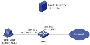
Configuration procedure
Make sure the settings on the switch and the RADIUS server match.
1. Configure the switch:
# Assign VLAN-interface 2 an IP address from the same subnet as the Telnet user.
<Switch> system-view
[Switch] interface vlan-interface 2
[Switch-Vlan-interface2] ip address 192.168.1.70 255.255.255.0
[Switch-Vlan-interface2] quit
# Assign VLAN-interface 3 an IP address from the same subnet as the RADIUS server.
[Switch] interface vlan-interface 3
[Switch-Vlan-interface3] ip address 10.1.1.2 255.255.255.0
[Switch-Vlan-interface3] quit
# Enable Telnet server.
[Switch] telnet server enable
# Enable scheme authentication on the user lines for Telnet users.
[Switch] user-interface vty 0 63
[Switch-line-vty0-63] authentication-mode scheme
[Switch-line-vty0-63] quit
# Create a RADIUS scheme named rad and enter RADIUS scheme view.
[Switch] radius scheme rad
# Specify the primary server address 10.1.1.1 and the service port 1812 in the scheme.
[Switch-radius-rad] primary authentication 10.1.1.1 1812
# Set the shared key to expert in the scheme for the switch to authenticate to the server.
[Switch-radius-rad] key authentication simple expert
[Switch-radius-rad] quit
# Specify the scheme rad as the authentication and authorization schemes for the ISP domain bbb.
|
|
IMPORTANT: Because RADIUS user authorization information is piggybacked in authentication responses, the authentication and authorization methods must use the same RADIUS scheme. |
[Switch] domain bbb
[Switch-isp-bbb] authentication login radius-scheme rad
[Switch-isp-bbb] authorization login radius-scheme rad
[Switch-isp-bbb] quit
# Create a feature group named fgroup1.
[Switch] role feature-group name fgroup1
# Add the features arp and radius to the feature group.
[Switch-featuregrp-fgroup1] feature arp
[Switch-featuregrp-fgroup1] feature radius
[Switch-featuregrp-fgroup1] quit
# Create a user role named role2.
[Switch] role name role2
# Configure rule 1 to permit the user role to use all commands available in ISP view.
[Switch-role-role2] rule 1 permit command system-view ; domain *
# Configure rule 2 to permit the user role to use read and write commands of all features in fgroup1.
[Switch-role-role2] rule 2 permit read write feature-group fgroup1
# Configure rule 3 to disable access to the read commands of the acl feature.
[Switch-role-role2] rule 3 deny read feature acl
# Configure rule 4 to permit the user role to create VLANs and use all commands available in VLAN view.
[Switch-role-role2] rule 4 permit command system-view ; vlan *
# Configure rule 5 to permit the user role to enter interface view and use all commands available in interface view.
[Switch-role-role2] rule 5 permit command system-view ; interface *
# Configure the user role VLAN policy to disable configuration of any VLAN except VLANs 1 to 20.
[Switch-role-role2] vlan policy deny
[Switch-role-role2-vlanpolicy] permit vlan 1 to 20
[Switch-role-role2-vlanpolicy] quit
# Configure the user role interface policy to disable configuration of any interface except FortyGigE 1/0/1 to FortyGigE 1/0/24.
[Switch-role-role2] interface policy deny
[Switch-role-role2-ifpolicy] permit interface fortygige 1/0/1 to fortygige 1/0/24
[Switch-role-role2-ifpolicy] quit
[Switch-role-role2] quit
2. Configure the RADIUS server:
# Add either of the user role attributes to the dictionary file of the FreeRADIUS server.
Cisco-AVPair = "shell:roles=\"role2\""
Cisco-AVPair = "shell:roles*\"role2\""
# Configure the settings required for the FreeRADIUS server to communicate with the switch. (Details not shown.)
Verifying the configuration
# Telnet to the switch, and enter the username and password to access the switch. (Details not shown.)
# Verify that you can use all commands available in ISP view.
<Switch> system-view
[Switch] domain abc
[Switch-isp-abc] authentication login radius-scheme abc
[Switch-isp-abc] quit
# Verify that you can use all read and write commands of the features radius and arp. Take radius as an example.
[Switch] radius scheme rad
[Switch-radius-rad] primary authentication 2.2.2.2
[Switch-radius-rad] display radius scheme rad
…
Output of the RADIUS scheme is omitted.
# Verify that you cannot configure any VLAN except VLANs 1 to 20. Take VLAN 10 and VLAN 30 as examples.
[Switch] vlan 10
[Switch-vlan10] quit
[Switch] vlan 30
Permission denied.
# Verify that you cannot configure any interface except FortyGigE 1/0/1 to FortyGigE 1/0/24. Take FortyGigE 1/0/2 and FortyGigE 1/0/25 as examples.
[Switch] vlan 10
[Switch-vlan10] port fortygige 1/0/2
[Switch-vlan10] port fortygige 1/0/25
Permission denied.
RBAC configuration example for HWTACACS authentication users
Network requirements
As shown in Figure 20, the switch uses local authentication for login users, including the Telnet user at 192.168.1.58. The Telnet user uses the username test@bbb and is assigned the user role level-0.
Configure the remote-then-local authentication mode for temporary user role authorization. The switch uses the HWTACACS server to provide authentication for obtaining the level-3 user role. If the AAA configuration is invalid or the HWTACACS server does not respond, the switch performs local authentication.
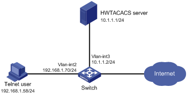
Configuration procedure
1. Configure the switch:
# Assign an IP address to VLAN-interface 2, the interface connected to the Telnet user.
<Switch> system-view
[Switch] interface vlan-interface 2
[Switch-Vlan-interface2] ip address 192.168.1.70 255.255.255.0
[Switch-Vlan-interface2] quit
# Assign an IP address to VLAN-interface 3, the interface connected to the HWTACACS server.
[Switch] interface vlan-interface 3
[Switch-Vlan-interface3] ip address 10.1.1.2 255.255.255.0
[Switch-Vlan-interface3] quit
# Enable Telnet server.
[Switch] telnet server enable
# Enable scheme authentication on the user lines for Telnet users.
[Switch] line vty 0 63
[Switch-line-vty0-63] authentication-mode scheme
[Switch-line-vty0-63] quit
# Enable remote-then-local authentication for temporary user role authorization.
[Switch] super authentication-mode scheme local
# Create an HWTACACS scheme named hwtac and enter HWTACACS scheme view.
[Switch] hwtacacs scheme hwtac
# Specify the primary authentication server address 10.1.1.1 and the service port 49 in the scheme.
[Switch-hwtacacs-hwtac] primary authentication 10.1.1.1 49
# Set the shared key to expert in the scheme for the switch to authenticate to the server.
[Switch-hwtacacs-hwtac] key authentication simple expert
# Exclude the ISP domain name from the username sent to the HWTACACS server.
[Switch-hwtacacs-hwtac] user-name-format without-domain
[Switch-hwtacacs-hwtac] quit
# Create an ISP domain named bbb and enter ISP domain view.
[Switch] domain bbb
# Configure the ISP domain bbb to use local authentication for login users.
[Switch-isp-bbb] authentication login local
# Configure the ISP domain bbb to use local authorization for login users.
[Switch-isp-bbb] authorization login local
# Apply the HWTACACS scheme hwtac to the ISP domain for user role authentication.
[Switch-isp-bbb] authentication super hwtacacs-scheme hwtac
[Switch-isp-bbb] quit
# Create a device management user named test and enter local user view. Set the service type to Telnet, and set the password to aabbcc.
[Switch] local-user test class manage
[Switch-luser-manage-test] service-type telnet
[Switch-luser-manage-test] password simple aabbcc
# Assign level-0 to the user.
[Switch-luser-manage-test] authorization-attribute user-role level-0
# Delete the default user role network-operator.
[Switch-luser-manage-test] undo authorization-attribute user-role network-operator
[Switch-luser-manage-test] quit
# Set the local authentication password to 654321 for the user role level-3.
[Switch] super password role level-3 simple 654321
[Switch] quit
2. Configure the HWTACACS server:
This example uses ACSv4.0.
Perform the following tasks on the User Setup page:
a. Add a user account test. (Details not shown.)
b. In the Advanced TACACS+ Settings area, configure the following parameters:
- Select Level 3 for the Max Privilege for any AAA Client option.
- Select the Use separate password option, and specify enabpass as the password.
Figure 21 Configuring advanced TACACS+ settings
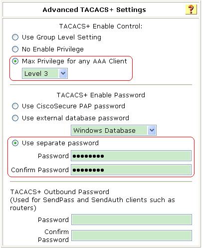
Verifying the configuration
1. Telnet to the switch, and enter the username test@bbb and password aabbcc to access the switch. Verify that you have access to diagnostic commands.
<Switch> telnet 192.168.1.70
Trying 192.168.1.70 ...
Press CTRL+K to abort
Connected to 192.168.1.59 ...
******************************************************************************
* Copyright (c) 2004-2014 Hangzhou H3C Tech. Co., Ltd. All rights reserved. *
* Without the owner's prior written consent, *
* no decompiling or reverse-engineering shall be allowed. *
******************************************************************************
login: test@bbb
Password:
<Switch>?
User view commands:
ping Ping function
quit Exit from current command view
ssh2 Establish a secure shell client connection
super Switch to a user role
system-view Enter the System View
telnet Establish a telnet connection
tracert Tracert function
<Switch>
2. Verify that you can obtain the level-3 user role:
# Use the super password to obtain the level-3 user role. When the system prompts for a username and password, enter the username test@bbb and password enabpass.
<Switch> super level-3
Username: test@bbb
Password:
The following output shows that you have obtained the level-3 user role.
User privilege role is level-3, and only those commands that authorized to the role can be used.
# If the ACS server does not respond, enter the local authentication password 654321 at the prompt.
Invalid configuration or no response from the authentication server.
Change authentication mode to local.
Password:
User privilege role is level-3, and only those commands that authorized to the role can be used.
The output shows that you have obtained the level-3 user role.
Troubleshooting RBAC
This section describes several typical RBAC problems and their solutions.
Local users have more access permissions than intended
Symptom
A local user can use more commands than should be permitted by the assigned user roles.
Analysis
The local user might have been assigned to user roles without your knowledge. For example, the local user is automatically assigned a default user role when you create the local user.
Solution
To resolve the problem:
1. Use the display local-user command to examine the local user accounts for undesirable user roles, and delete them.
2. If the problem persists, contact H3C Support.
Login attempts by RADIUS users always fail
Symptom
Attempts by a RADIUS user to log in to the network access device always fail, even though the following conditions exist:
· The network access device and the RADIUS server can communicate with one another.
· All AAA settings are correct.
Analysis
RBAC requires that a login user have a minimum of one user role. If the RADIUS server does not authorize the login user to use any user role, the user cannot log in to the device.
Solution
To resolve the problem:
1. Use one of the following methods:
¡ Configure the role default-role enable command. A RADIUS user can log in with the default user role when no user role is assigned by the RADIUS server.
¡ Add the user role authorization attributes on the RADIUS server.
2. If the problem persists, contact H3C Support.
Configuring FTP
File Transfer Protocol (FTP) is an application layer protocol based on the client/server model. It is used to transfer files from one host to another over an IP network.
FTP server uses TCP port 20 to transfer data and TCP port 21 to transfer control commands. For more information about FTP, see RFC 959.
FTP supports the following transfer modes:
· Binary mode—Used to transfer image files, such as .app, .bin, and .btm files. This mode is also called "flow mode."
· ASCII mode—Used to transfer text files, such as .txt, .bat, and .cfg files.
By default, the transfer mode is binary.
FTP can operate in either of the following modes:
· Active mode (PORT)—The FTP server initiates the TCP connection. This mode is not suitable when the FTP client is behind a firewall, for example, when the FTP client resides in a private network.
· Passive mode (PASV)—The FTP client initiates the TCP connection. This mode is not suitable when the server does not allow the client to use a random unprivileged port greater than 1024.
FTP operation mode varies depending on the FTP client program.
The device can act as the FTP server or FTP client. Make sure the FTP server and the FTP client can reach each other before establishing the FTP connection.
Figure 22 FTP application scenario
FIPS compliance
The device supports the FIPS mode that complies with NIST FIPS 140-2 requirements. Support for features, commands, and parameters might differ in FIPS mode and non-FIPS mode. For more information about FIPS mode, see Security Configuration Guide.
FTP is not supported in FIPS mode.
Using the device as an FTP server
Perform the configuration tasks in this section to configure the device as an FTP server.
Configuring basic parameters
|
Step |
Command |
Remarks |
|
1. Enter system view. |
system-view |
N/A |
|
2. Enable the FTP server. |
ftp server enable |
By default, the FTP server is disabled. |
|
3. (Optional.) Use an ACL to control access to the FTP server. |
ftp server acl acl-number |
By default, no ACL is used for access control. |
|
4. (Optional.) Set the FTP connection idle-timeout timer. |
ftp timeout minutes |
By default, the FTP connection idle-timeout timer is 30 minutes. If no data transfer occurs on an FTP connection within the idle-timeout interval, the FTP server closes the FTP connection to release resources. |
|
5. (Optional.) Set the DSCP value for outgoing FTP packets. |
ftp server dscp dscp-value |
By default, the DSCP value is 0. |
|
6. (Optional.) Set the maximum number of concurrent FTP users. |
aaa session-limit ftp max-sessions |
By default, the maximum number of concurrent FTP users is 32. Changing this setting does not affect online users. If the current number of online FTP users is equal to or greater than the new setting, no additional FTP users can log in until online users log out. For more information about this command, see Security Command Reference. |
Configuring authentication and authorization
Perform this task on the FTP server to authenticate FTP clients and set the authorized directories that authenticated clients can access.
The following authentication modes are available:
· Local authentication—The device looks up the client's username and password in the local user account database. If a match is found, authentication succeeds.
· Remote authentication—The device sends the client's username and password to a remote authentication server for authentication. The user account is configured on the remote authentication server rather than the device.
The following authorization modes are available:
· Local authorization—The device assigns authorized directories to FTP clients based on the locally configured authorization attributes.
· Remote authorization—A remote authorization server assigns authorized directories on the device to FTP clients.
For information about configuring authentication and authorization, see Security Configuration Guide.
Manually releasing FTP connections
|
Task |
Command |
|
Manually release FTP connections. |
free ftp user username |
Displaying and maintaining the FTP server
Execute display commands in any view.
|
Task |
Command |
|
Display FTP server configuration and status information. |
display ftp-server |
|
Display detailed information about online FTP users. |
display ftp-user |
FTP server configuration example in standalone mode
Network requirements
On the device, create a local user account with the username abc and password 123456 and enable the FTP server.
From the PC, use the user account to log in to the FTP server and do the following:
· Upload the file temp.bin from the FTP client to the FTP server.
· Download the configuration file startup.cfg from the FTP server to the FTP client for backup.
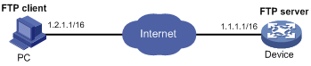
Configuration procedure
1. Configure IP addresses as shown in Figure 23, and make sure the device and PC can reach other. (Details not shown.)
2. Configure the device (FTP server):
# Create local user account abc and set the password to 123456.
<Sysname> system-view
[Sysname] local-user abc class manage
[Sysname-luser-manage-abc] password simple 123456
# Assign the user role network-admin to the user and set the working directory to the Flash root directory of the MPU.
[Sysname-luser-manage-abc] authorization-attribute user-role network-admin work-directory flash:/
# Assign the service type FTP to the user.
[Sysname-luser-manage-abc] service-type ftp
[Sysname-luser-manage-abc] quit
|
|
NOTE: If the password control feature is configured, the password must meet the password requirements defined by the feature. For more information, see Security Configuration Guide. |
# Enable the FTP server.
[Sysname] ftp server enable
[Sysname] quit
# Examine the storage space for space insufficiency and delete unused files for more free space.
<Sysname> dir
Directory of flash:
0 -rw- 0 Sep 27 2010 14:43:34 kernel.bin
1 -rw- 0 Sep 27 2010 14:43:34 base.bin
2 drw- - Jun 29 2011 18:30:38 logfile
3 drw- - Jun 21 2011 14:51:38 diagfile
4 drw- - Jun 21 2011 14:51:38 seclog
5 -rw- 2943 Jul 02 2011 08:03:08 startup.cfg
6 -rw- 63901 Jul 02 2011 08:03:08 startup.mdb
7 -rw- 716 Jun 21 2011 14:58:02 hostkey
8 -rw- 572 Jun 21 2011 14:58:02 serverkey
9 -rw- 6541264 Aug 04 2011 20:40:49 backup.bin
473664 KB total (467080 KB free)
<Sysname> delete /unreserved flash:/backup.bin
3. Perform FTP operations from the PC (FTP client):
# Log in to the FTP server at 1.1.1.1 using the username abc and password 123456.
c:\> ftp 1.1.1.1
Connected to 1.1.1.1.
220 FTP service ready.
User(1.1.1.1:(none)):abc
331 Password required for abc.
Password:
230 User logged in.
# Use the ASCII mode to download the configuration file startup.cfg from the device to the PC for backup.
ftp> ascii
200 TYPE is now ASCII
ftp> get startup.cfg back-startup.cfg
# Use the binary mode to upload the file temp.bin from the PC to the Flash root directory of the MPU.
ftp> binary
200 TYPE is now 8-bit binary
ftp> put temp.bin
# Exit FTP.
ftp> bye
FTP server configuration example in IRF mode
Network requirements
As shown in Figure 24, a two-chassis IRF fabric has two MPUs. The global active MPU is in slot 17 of the master. The global standby MPU is in slot 17 of the subordinate member.
On the device, create a local user account with the username abc and password 123456 and enable the FTP server.
From the PC, use the user account to log in to the FTP server and do the following:
· Upload the file temp.bin from the FTP client to the FTP server.
· Download the configuration file config.cfg from the FTP server to the FTP client for backup.

Configuration procedure
1. Configure IP addresses as shown in Figure 24, and make sure the IRF fabric and the PC can reach each other. (Details not shown.)
2. Configure the FTP server:
# Examine the storage space on the member devices. If the free space is insufficient, use the delete/unreserved file-url command to delete unused files. (Details not shown.)
# Create local user account abc and set the password to 123456.
<Sysname> system-view
[Sysname] local-user abc class manage
[Sysname-luser-manage-abc] password simple 123456
# Assign the user role network-admin to the user and set the working directory to the Flash root directory of the global active MPU. To set the working directory to the Flash root directory of the global standby MPU, replace flash:/ in the authorization-attribute command with chassis2#slot17#flash:/.
[Sysname-luser-manage-abc] authorization-attribute user-role network-admin work-directory flash:/
# Assign the service type FTP to the user.
[Sysname-luser-manage-abc] service-type ftp
[Sysname-luser-manage-abc] quit
|
|
NOTE: If the password control feature is configured, the password must meet the password requirements defined by the feature. For more information, see Security Configuration Guide. |
# Enable the FTP server.
[Sysname] ftp server enable
[Sysname] quit
3. Perform FTP operations from the FTP client:
# Log in to the FTP server at 1.1.1.1 using the username abc and password 123456.
c:\> ftp 1.1.1.1
Connected to 1.1.1.1.
220 FTP service ready.
User(1.1.1.1:(none)):abc
331 Password required for abc.
Password:
230 User logged in.
# Use the ASCII mode to download the configuration file config.cfg from the server to the client for backup.
ftp> ascii
200 TYPE is now ASCII
ftp> get config.cfg back-config.cfg
# Use the binary mode to upload the file temp.bin to the Flash root directory of the master.
ftp> binary
200 TYPE is now 8-bit binary
ftp> put temp.bin
# Exit FTP.
ftp> bye
Using the device as an FTP client
Establishing an FTP connection
To access the FTP server, you must establish a connection from the FTP client to the FTP server.
To establish an IPv4 FTP connection:
|
Step |
Command |
Remarks |
|
1. Enter system view. |
system-view |
N/A |
|
2. (Optional.) Specify a source IP address for outgoing FTP packets. |
ftp client source { interface interface-type interface-number | ip source-ip-address } |
By default, no source IP address is specified, and the primary IP address of the output interface is used as the source IP address. |
|
3. Return to user view. |
quit |
N/A |
|
4. Log in to the FTP server. |
·
(Method 1.) Log in to the
FTP server directly from user
view: · (Method 2.) Log in to the FTP server from FTP client view: a. ftp b. open server-address [ service-port ] |
Use either method. The source IP address specified in the ftp command takes precedence over the one set by the ftp client source command. |
Managing directories on the FTP server
|
Task |
Command |
|
Display directory and file information on the FTP server. |
·
Display the detailed information of a directory
or file on the FTP server: ·
Display the name of a directory or file on the
FTP server: |
|
Change the working directory on the FTP server. |
cd { directory | .. | / } |
|
Return to the upper level directory on the FTP server. |
cdup |
|
Display the working directory that is being accessed. |
pwd |
|
Create a directory on the FTP server. |
mkdir directory |
|
Delete a directory from the remote FTP server. |
rmdir directory |
Working with files on the FTP server
After you log in to the server, you can upload a file to or download a file from the authorized directory by following these steps:
1. Use the dir or ls command to display the directory and location of the file on the FTP server.
2. Delete unused files to get more free storage space.
3. Set the file transfer mode to ASCII for text files or binary for image files.
4. Use the lcd command to change the local working directory of the FTP client. You can upload the file or save the downloaded file in this directory.
5. Upload or download the file.
To work with files on an FTP server, execute the following commands in FTP client view:
|
Task |
Command |
Remarks |
|
Display directory or file information on the FTP server. |
·
Display the detailed information of a directory or file on the FTP server: ·
Display the name of a directory or file on the
FTP server: |
N/A |
|
Delete the specified file on the FTP server permanently. |
delete remotefile |
N/A |
|
Set the file transfer mode to ASCII. |
ascii |
The default file transfer mode is binary. |
|
Set the file transfer mode to binary. |
binary |
The default file transfer mode is binary. |
|
Set the FTP operation mode to passive. |
passive |
The default mode is passive. |
|
Display or change the local working directory of the FTP client. |
lcd [ directory | / ] |
N/A |
|
Upload a file to the FTP server. |
put localfile [ remotefile ] |
N/A |
|
Download a file from the FTP server. |
get remotefile [ localfile ] |
N/A |
|
Add the content of a file on the FTP client to a file on the FTP server. |
append localfile [ remotefile ] |
N/A |
|
Specify the retransmit marker. |
restart marker |
Use this command together with the put, get, or append command. |
|
Update the local file. |
newer remotefile |
N/A |
|
Get the missing part of a file. |
reget remotefile [ localfile ] |
N/A |
|
Rename the file. |
rename [ oldfilename [ newfilename ] ] |
N/A |
Changing to another user account
After you log in to the FTP server with one user account, you can change to another user account to get a different privilege without reestablishing the FTP connection. You must correctly enter the new username and password. A wrong username or password can cause the FTP connection to disconnect.
To change to another user account, execute the following command in user view:
|
Task |
Command |
|
Change to another user account. |
user username [ password ] |
Maintaining and troubleshooting the FTP connection
|
Task |
Command |
Remarks |
|
Display FTP commands on the FTP server. |
rhelp |
N/A |
|
Display FTP commands help information on the FTP server. |
rhelp protocol-command |
N/A |
|
Display FTP server status. |
rstatus |
N/A |
|
Display detailed information about a directory or file on the FTP server. |
rstatus remotefile |
N/A |
|
Display FTP connection status. |
status |
N/A |
|
Display the system information of the FTP server. |
system |
N/A |
|
Enable or disable FTP operation information displaying. |
verbose |
By default, FTP operation information displaying is enabled. |
|
Enable or disable FTP client debugging. |
debug |
By default, FTP client debugging is disabled. |
|
Clear the reply information in the buffer. |
reset |
N/A |
Terminating the FTP connection
|
Task |
Command |
Remarks |
|
Terminate the connection to the FTP server without exiting FTP client view. |
· disconnect · close |
Use either command in FTP client view. |
|
Terminate the connection to the FTP server and return to user view. |
· bye · quit |
Use either command in FTP client view. |
Displaying command help information
To display command help information after you log in to the server:
|
Task |
Command |
Remarks |
|
Display command help information. |
· help [ command-name ] · ? [ command-name ] |
Use either command. |
Displaying and maintaining FTP client
Execute the display command in any view.
|
Task |
Command |
|
Display source IP address information on the FTP client. |
display ftp client source |
FTP client configuration example in standalone mode
Network requirements
As shown in Figure 25, a PC acts as the FTP server. An FTP user account with the username abc and password 123456 is configured on the FTP server.
Use the device as the FTP client to log in to the FTP server and do the following:
· Download the file temp.bin from the PC to the device.
· Upload the configuration file startup.cfg from the device to the PC for backup.
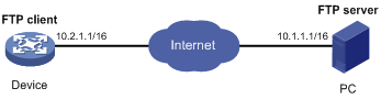
Configuration procedure
# Configure IP addresses as shown in Figure 25 and make sure the device and PC can reach each other. (Details not shown.)
# Examine the storage space of the device. If the free space is insufficient, use the delete/unreserved file-url command to delete unused files. (Details not shown.)
# Log in to the FTP server at 10.1.1.1 using the username abc and password 123456.
<Sysname> ftp 10.1.1.1
Press CTRL+C to abort.
Connected to 10.1.1.1 (10.1.1.1).
220 WFTPD 2.0 service (by Texas Imperial Software) ready for new user
User (10.1.1.1:(none)): abc
331 Give me your password, please
Password:
230 Logged in successfully
Remote system type is MSDOS.
200 Type is Image (Binary)
# Download the file temp.bin from the PC to the device.
ftp> get temp.bin
local: temp.bin remote: temp.bin
150 Connecting to port 47457
226 File successfully transferred
23951480 bytes received in 95.399 seconds (251.0 kbyte/s)
# Set the file transfer mode to ASCII. Upload the configuration file startup.cfg from the device to the PC for backup.
ftp> ascii
200 TYPE is now ASCII
ftp> put startup.cfg back-startup.cfg
local: startup.cfg remote: back-startup.cfg
150 Connecting to port 47461
226 File successfully transferred
3494 bytes sent in 5.646 seconds (618.00 kbyte/s)
ftp> bye
221-Goodbye. You uploaded 2 and downloaded 2 kbytes.
221 Logout.
<Sysname>
FTP client configuration example in IRF mode
Network requirements
As shown in Figure 26, a PC acts as the FTP server. An FTP user account with the username abc and password 123456 is configured on the FTP server. A two-chassis IRF fabric has two MPUs. The global active MPU is in slot 17 of the master. The global standby MPU is in slot 17 of the subordinate member.
Use the IRF fabric as the FTP client to log in to the FTP server and do the following:
· Download the file temp.bin from the PC to the IRF fabric.
· Upload the configuration file config.cfg from the IRF fabric to the PC for backup.
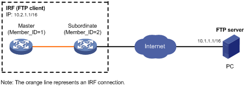
Configuration procedure
# Configure IP addresses for devices and make sure they can reach other. (Details not shown.)
# Examine the storage space on the member devices. If the free space is insufficient, use the delete/unreserved file-url command to delete unused files. (Details not shown.)
# Log in to the FTP server using the username abc and password 123456.
<Sysname> ftp 10.1.1.1
Press CTRL+C to abort.
Connected to 10.1.1.1 (10.1.1.1).
220 WFTPD 2.0 service (by Texas Imperial Software) ready for new user
User (10.1.1.1:(none)): abc
331 Give me your password, please
Password:
230 Logged in successfully
Remote system type is MSDOS.
200 Type is Image (Binary)
# Download the file temp.bin from the PC to the Flash root directory of the global active MPU.
ftp> get temp.bin
local: temp.bin remote: temp.bin
150 Connecting to port 47457
226 File successfully transferred
23951480 bytes received in 95.399 seconds (251.0 kbyte/s)
# Download the file temp.bin from the PC to the Flash root directory of the global standby MPU.
ftp> get temp.bin chassis2#slot17#flash:/temp.bin
# Upload the configuration file config.cfg from the IRF fabric to the PC for backup.
ftp> ascii
200 TYPE is now ASCII
ftp> put config.cfg back-config.cfg
local: config.cfg remote: back-config.cfg
150 Connecting to port 47461
226 File successfully transferred
3494 bytes sent in 5.646 seconds (618.00 kbyte/s)
ftp> bye
221-Goodbye. You uploaded 2 and downloaded 2 kbytes.
221 Logout.
<Sysname>
Configuring TFTP
Trivial File Transfer Protocol (TFTP) is a simplified version of FTP for file transfer over secure reliable networks. TFTP uses UDP port 69 for data transmission. In contrast to TCP-based FTP, TFTP does not require authentication or complex message exchanges, and is easier to deploy. TFTP is suited for reliable network environments.
The device can only act as a TFTP client. You can upload a file from the device to the TFTP server or download a file from the TFTP server to the device. If you download a file with a file name that exists in the target directory, the device deletes the existing file and saves the new one. If file download fails due to network disconnection or other reasons, the original file cannot be restored. Therefore, use a nonexistent file name instead.
Figure 27 TFTP application scenario
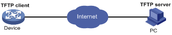
FIPS compliance
The device supports the FIPS mode that complies with NIST FIPS 140-2 requirements. Support for features, commands, and parameters might differ in FIPS mode and non-FIPS mode. For more information about FIPS mode, see Security Configuration Guide.
TFTP is not supported in FIPS mode.
Configuring the device as an IPv4 TFTP client
|
Step |
Command |
Remarks |
|
1. Enter system view. |
system-view |
N/A |
|
2. (Optional.) Use an ACL to control the client's access to TFTP servers. |
tftp-server acl acl-number |
By default, no ACL is used for access control. |
|
3. Specify the source IP address for TFTP packets sent by the TFTP client. |
tftp client source { interface interface-type interface-number | ip source-ip-address } |
By default, no source IP address is specified, and the primary IP address of the output interface is used as the source IP address. |
|
4. Return to user view. |
quit |
N/A |
|
5. Download or upload a file in an IPv4 network. |
tftp tftp-server { get | put | sget } source-filename [ destination-filename ] [ vpn-instance vpn-instance-name ] [ dscp dscp-value | source { interface interface-type interface-number | ip source-ip-address } ] * |
The source IP address specified in this command takes precedence over the one set by the tftp client source command. Use this command in user view. |
Managing the file system
This chapter describes how to manage the device's file system, including the storage media, directories, and files.
|
|
IMPORTANT: · Before managing storage media, files, and directories, make sure you know the possible impacts. · A file or directory whose name starts with a period (.) is considered a hidden file or directory. Do not give a common file or directory a name that starts with a period. · Some system files and directories are hidden. |
Storage medium naming rules
The device supports the following types of storage media:
· Flash memory—The Flash is named flash.
· USB disk—The USB disk can be partitioned, and the partitions are numbered. For example, the first partition is named usb0, and the second partition is named usb1.
File name formats
|
|
IMPORTANT: Enter a storage medium name in lower case, including the chassis and slot strings (if any). Otherwise, the following error message is displayed: "The file or directory doesn't exist." Folder names and file names are case insensitive. |
When you specify a file, enter the file name in one of the formats shown in Table 12 and Table 13. When you specify a directory, follow the rules for the drive and path arguments.
Table 12 File name formats in standalone mode
|
Format |
Description |
Example |
|
file-name |
Specifies a file in the current working directory. |
a.cfg indicates a file named a.cfg in the current working directory. |
|
[path/]file-name |
Specifies a file in a specific folder in the current working directory. The path argument represents the path to the file. If the file is in a single-level folder, specify the folder name for the argument. If the file is in a nested folder, separate each folder name by a forward slash (/). |
· test/a.cfg indicates a file named a.cfg in the test folder in the current working directory. · test/subtest/a.cfg indicates a file named a.cfg in the subtest subfolder of the test folder in the current working directory. |
|
drive:/[path]/file-name |
Specifies a file in a specific storage medium. The drive argument represents the storage medium name: · For a storage medium on the active MPU, it is flash or usb0. · For a storage medium on the standby MPU, it is slotn#flash or slotn#usb0. The n represents the slot number of the standby MPU. To view MPUs' slot numbers, use the display device command. |
flash:/test/a.cfg indicates a file named a.cfg in the test folder of the MPU's flash memory. · flash:/test/a.cfg indicates a file named a.cfg in the test folder of the active MPU's flash memory. · slot16#flash:/a.cfg indicates a file named a.cfg in the root directory of standby MPU's flash memory. |
Table 13 File name formats in IRF mode
|
Format |
Description |
Example |
|
file-name |
Specifies a file in the current working directory. |
a.cfg indicates a file named a.cfg in the current working directory. This working directory might be on any MPU in the IRF fabric. |
|
[path/]file-name |
Specifies a file in a specific folder in the current working directory. The path argument represents the path to the file. If the file is in a single-level folder, specify the folder name for the argument. If the file is in a nested folder, separate each folder name by a forward slash (/). |
· test/a.cfg indicates a file named a.cfg in the test folder in the current working directory. · test/subtest/a.cfg indicates a file named a.cfg in the subtest subfolder of the test folder in the current working directory. |
|
drive:/[path]/file-name |
Specifies a file in a specific storage medium on the device. The drive argument represents the storage medium name: · For a storage medium on the global active MPU, it is flash or usb0. · For a storage medium on a global standby MPU, it is chassism#slotn#flash or chassism#slotn#usb0. The m represents the member ID of the subordinate device. The n represents the slot number of the MPU. To view member devices' member IDs, use the display irf command. |
· flash:/test/a.cfg indicates a file named a.cfg in the test folder on the global active MPU's flash memory. · chassis2#slot0#flash:/a.cfg indicates a file named a.cfg in the root directory of the flash memory on a global standby MPU (in slot 0 of member device 2). |
Managing files
|
|
CAUTION: To avoid file system corruption, do not perform the following operations during file operations: · Installing or removing storage media. · Performing an active/standby switchover in standalone mode. · Performing a switchover between the global active MPU and a global standby MPU in IRF mode. |
You can perform the following file management tasks:
· Display directory and file information.
· Display file contents.
· Rename, copy, move, remove, restore, delete, compress, decompress, archive, and extract files.
· Calculate the digests of files for file integrity verification.
You can create a file by copying, downloading, or using the save command. For more information about downloading a file, see "Configuring FTP" and "Configuring TFTP." For more information about the save command, see Fundamentals Command Reference.
Before you rename, compress, decompress, delete, restore, or move a file on a USB disk, or copy a file to a USB disk, make sure the disk is not write protected.
Displaying file information
Perform this task in user view.
|
Task |
Command |
|
Display folder or file information. |
dir [ /all ] [ file-url | /all-filesystems ] |
Displaying the contents of a text file
Perform this task in user view.
|
Task |
Command |
|
Display the contents of a text file. |
more file-url |
Renaming a file
Perform this task in user view.
|
Task |
Command |
|
Rename a file. |
rename fileurl-source fileurl-dest |
Copying a file
Perform this task in user view.
|
Task |
Command |
|
Copy a file. |
copy fileurl-source fileurl-dest |
Moving a file
Perform this task in user view.
|
Task |
Command |
|
Move a file. |
move fileurl-source fileurl-dest |
Compressing/decompressing a file
Perform the following tasks in user view:
|
Task |
Command |
|
Compress a file. |
gzip filename |
|
Decompress a file. |
gunzip filename |
Archiving/extracting files
Perform the following tasks in user view:
|
Task |
Command |
|
Archive files. |
tar create [ gz ] archive-file fileurl-dest [ verbose ] source fileurl-source-list&<1-5> |
|
Extract files. |
tar extract archive-file fileurl-dest [ verbose ] [ screen | to directory-name ] |
|
Display the names of archived files. |
tar list archive-file fileurl-dest |
Deleting/restoring a file
You can delete a file permanently or move it to the recycle bin. A file moved to the recycle bin can be restored, but a permanently deleted file cannot.
Files in the recycle bin occupy storage space. To save storage space, periodically empty the recycle bin with the reset recycle-bin command.
Perform the following tasks in user view:
|
Task |
Command |
|
Delete a file by moving it to the recycle bin. |
delete file-url |
|
Restore a file from the recycle bin. |
undelete file-url |
|
Delete a file permanently. |
delete /unreserved file-url |
|
|
IMPORTANT: Do not use the delete command to delete files from the recycle bin. To delete files from the recycle bin, use the reset recycle-bin command. |
Deleting files from the recycle bin
The device supports multiple storage media. Each storage medium has a recycle bin of its own.
The device supports multiple storage media. If a storage medium is not partitioned, it has a recycle bin of its own. If a storage medium is partitioned, each partition has its own recycle bin.
A recycle bin is a folder named .trash in the root directory of the storage medium or partition.
To view which files or directories are in a recycle bin, use either of the following methods:
· Enter the storage medium or partition and execute the dir/all .trash command.
· Execute the cd .trash command to enter the recycle bin folder and then execute the dir command.
To delete files from a recycle bin, perform the following task in user view:
|
Task |
Command |
|
Delete files from the recycle bin. |
reset recycle-bin [ /force ] |
Calculating the digest of a file
File digests are used to verify file integrity. For example, you can calculate the digest of a software image file and compare it with that provided on the H3C website to verify whether the file has been tampered with.
Perform this task in user view.
|
Task |
Command |
|
Calculate the digest of a file. |
·
To use the SHA-256 algorithm: ·
To use the MD5 algorithm: |
Managing directories
|
CAUTION: To avoid file system corruption, do not perform the following operations during file operations: · Installing or removing storage media. · Performing an active/standby switchover in standalone mode. · Performing a switchover between the global active MPU and a global standby MPU in IRF mode. |
You can perform the following directory management tasks:
· Create or delete a directory.
· Display or change the current working directory.
· Display a specific directory.
Before you create or delete a directory on a USB disk, make sure the disk is not write protected.
Displaying directory information
Perform this task in user view.
|
Task |
Command |
|
Display directory or file information. |
dir [ /all ] [ file-url | /all-filesystems ] |
Displaying the current working directory
Perform this task in user view.
|
Task |
Command |
|
Display the current working directory. |
pwd |
Changing the current working directory
Perform this task in user view.
|
Task |
Command |
|
Change the current working directory. |
cd { directory | .. | / } |
Creating a directory
Perform this task in user view.
|
Task |
Command |
|
Create a directory. |
mkdir directory |
Deleting a directory
To delete a directory, you must delete all files and subdirectories in this directory. To delete a file, use the delete command. To delete a subdirectory, use the rmdir command.
Deleting a directory permanently deletes all its files in the recycle bin, if any.
Perform this task in user view.
|
Task |
Command |
|
Delete a directory. |
rmdir directory |
Managing storage media
|
|
CAUTION: To avoid file system corruption, do not perform the following operations while the system is repairing, formatting, partitioning, mounting, or unmounting a storage medium: · Installing or removing storage media or cards. · Performing an active/standby switchover in standalone mode. · Performing a switchover between the global active MPU and a global standby MPU in IRF mode. |
If you remove a storage medium while a folder or file on the storage medium is being accessed, the device might not recognize the storage medium when you reinstall it. To reinstall this kind of a storage medium, complete one of the following tasks:
· If you were accessing a folder on the storage medium, change the current directory.
· If you were accessing a file on the storage medium, close the file.
· If another administrator was accessing the storage medium, unmount all partitions on the storage medium.
Before you repair or format a USB disk, make sure the disk is not write protected.
Repairing a storage medium
If part of a storage medium is inaccessible, use the fixdisk command to examine and repair the medium.
Before repairing a storage medium, make sure no other users are accessing the medium. Otherwise, the repair operation fails.
Perform this task in user view.
|
Task |
Command |
|
Repair a storage medium. |
fixdisk medium-name |
Formatting a storage medium
|
|
CAUTION: After a storage medium is formatted, all files and directories on it are erased and cannot be restored. |
To format a storage medium that has been partitioned, you must format all the partitions individually, instead of formatting the medium as a whole. You can format a storage medium only when no one is accessing the medium.
Perform this task in user view.
|
Task |
Command |
|
Format a storage medium. |
format medium-name |
Mounting or unmounting a storage medium
Generally, a hot-swappable storage medium is automatically mounted when it is connected to the device. If the system cannot recognize the storage medium, however, you must mount the storage medium before you can access it.
To remove a hot-swappable storage medium from the device, you must first unmount it to disconnect it from the device. Otherwise, files on the storage medium or even the storage medium itself might be damaged.
Restrictions and guidelines
To mount/unmount a partitioned storage medium, you must mount/unmount all the partitions individually, instead of mounting/unmounting the medium as a whole. To unmount a USB disk, make sure the system has recognized the USB disk and the USB disk LED is not blinking. Otherwise, the USB interface or USB disk might be damaged.
Before unmounting a storage medium, make sure no other users are accessing the medium. Otherwise, the unmount operation fails.
Configuration procedure
Perform one of the following tasks in user view as appropriate:
|
Task |
Command |
Remarks |
|
Mount a storage medium. |
mount medium-name |
By default, a storage medium is automatically mounted and in mounted state when connected to the system. |
|
Unmount a storage medium. |
umount medium-name |
By default, a storage medium is automatically mounted and in mounted state when connected to the system. |
Partitioning a USB disk
A USB disk can be divided into logical devices called "partitions." Operations on one partition do not affect the other partitions.
The following partitioning modes are available for USB disks:
· Simple—Specify the number of partitions. The system divides the USB disk into the specified number of partitions with the same size.
· Interactive—The system partitions the USB disk according to user input. Each partition must be at least 32 MB.
Restrictions and guidelines
It is normal that the specified partition size and the actual partition size have an error less than 5% of the total memory.
Before partitioning a USB disk:
· Back up the files in the storage medium. The partition operation clears all data in the medium.
· If you are partitioning a USB disk, make sure the disk is not write protected. Otherwise, the partition operation will fail, and you must remount or reinstall the disk to restore access to the USB disk.
· Make sure no other users are accessing the medium. Otherwise, the partition operation fails.
After partitioning a USB disk:
· Reconfigure paths of application files to include the correct partition information.
· To guarantee the startup system software image and configuration files sufficient storage space, set the path for log files to a partition other than the first partition. By default, the system automatically saves log files to the second partition. If the path does not exist, use the info-center logfile switch-directory command to change the path to avoid log loss. For more information about this command, see Network Management and Monitoring Command Reference.
Configuration procedure
Perform this task in user view.
|
Task |
Command |
Remarks |
|
Partition a storage medium. |
fdisk medium-name [ partition-number ] |
By default, only one partition usb0:/ is available on a USB disk. |
Setting the operation mode for files and folders
The device supports the following file and folder operation modes:
· alert—The system prompts for confirmation when your operation might cause problems such as file corruption and data loss. This mode provides an opportunity to cancel a disruptive operation.
· quiet—The system does not prompt for confirmation.
To set the operation mode for files and folders:
|
Step |
Command |
Remarks |
|
1. Enter system view. |
system-view |
N/A |
|
2. Set the operation mode for files and folders. |
file prompt { alert | quiet } |
The default mode is alert. |
Managing configuration files
Overview
A configuration file saves a set of commands for configuring software features on the device. You can save any configuration to a configuration file so they can survive a reboot. You can also back up configuration files to a host for future use.
You can use the CLI or the BootWare menus to manage configuration files. This chapter explains how to manage configuration files from the CLI.
Configuration types
The configuration loaded at startup is called startup configuration and the configuration that is running on the device is called running configuration in this chapter.
Startup configuration
The device uses startup configuration to configure software features during startup.
The following are sources of startup configuration:
· Initial settings—Initial values or states for parameters. If the device starts up with empty configuration, all parameters use their initial settings at startup.
· Startup configuration file—Configuration file you specify in the BootWare menus or CLI for startup. The file is called the next-startup configuration file. After the file is loaded at startup, it is also called the current startup configuration file. For high availability, you can specify two next-startup configuration files, one main and one backup (see "Specifying a next-startup configuration file").
To display the current startup configuration file and the next-startup configuration files, use the display startup command.
To display the contents of the configuration file for the next system startup, use the display saved-configuration command.
Running configuration
The running configuration includes startup settings that have not been changed and new settings you made. The running configuration is stored in the memory and is cleared at a device reboot or power off. To use the running configuration after a power cycling or reboot, save it to a configuration file.
To view the running configuration, use the display current-configuration command. The displayed configuration does not include parameters that use initial settings.
Startup configuration loading process
Figure 28 shows the configuration loading process during startup.
Figure 28 Configuration loading process during startup
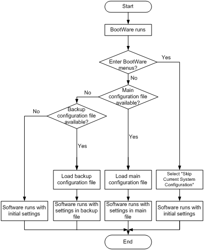
The device uses the following process to select the configuration to load at startup:
1. If you access the BootWare menus to select the Skip Current System Configuration option, the device starts up with empty configuration. All parameters use their initial settings.
2. If you do not access the BootWare menus to select the Skip Current System Configuration option, the following process applies:
a. If you have specified a main startup configuration file, and this configuration file is available, the device starts up with this startup configuration file.
b. If you have not specified a main startup configuration file, or the specified main startup configuration file is not available, the device searches for the backup startup configuration file.
c. If you have not specified a backup startup configuration file, or the specified backup startup configuration file is not available, the device starts up with initial settings.
Configuration file formats
Configuration files you specify for saving configuration must use the .cfg extension. A .cfg configuration file is a human-readable text file. When you save configuration to a .cfg file, the device automatically saves the configuration to an .mdb binary file that has the same name as the .cfg file. The device loads an .mdb file faster than loading a .cfg file. You are allowed to delete an .mdb file but disallowed to create an .mdb file or access its contents.
Startup configuration file selection
At startup, the device uses the following procedure to identify the configuration file to load:
1. The device searches for a valid .cfg next-startup configuration file.
2. If one is found, the device searches for an .mdb file that has the same name and content as the .cfg file.
3. If an .mdb file has the same name and content as the .cfg file, the device starts up with the .mdb file. If none is found, the device starts up with the .cfg file.
Unless otherwise stated, the term "configuration file" in this document refers to a .cfg configuration file.
Configuration file content organization and format
|
|
IMPORTANT: To run on the device, a configuration file must meet the content and format requirements. To ensure a successful configuration load at startup, use a configuration file that was automatically created on the device or created by using the save command. If you edit the configuration file, make sure all edits are compliant with the requirements. |
A configuration file must meet the following requirements:
· All commands are saved in their complete form.
· Commands are sorted in sections by different command views, including system view, interface view, protocol view, and user line view.
· Two adjacent sections are separated by a comment line that starts with a pound sign (#).
· The configuration file ends with the word return.
The following is a sample configuration file excerpt:
#
local-user root
password hash $h$6$Twd73mLrN8O2vvD5$Cz1vgdpR4KoTiRQNE9pg33gU14Br2p1VguczLSVyJLO2huV5Syx/LfDIf8ROLtVErJ/C31oq2rFtmNuyZf4STw==
service-type ssh telnet terminal
authorization-attribute user-role network-admin
#
interface FortyGigE1/0/1
port link-mode route
ip address 1.1.1.1 255.255.255.0
#
FIPS compliance
The device supports the FIPS mode that complies with NIST FIPS 140-2 requirements. Support for features, commands, and parameters might differ in FIPS mode and non-FIPS mode. For more information about FIPS mode, see Security Configuration Guide.
General configuration restrictions and guidelines
When you manage the next-startup configuration files, follow these restrictions and guidelines:
· Save the next-startup configuration files to the root directory of the default storage medium on each MPU. The device loads startup configuration files only from the default storage medium. You can access the BootWare menus to specify the built-in flash memory or the USB disk as the default storage medium.
· Make sure all MPUs use the same type of storage medium as the default storage medium.
· If the USB disk is used to store the startup configuration files, the file must be saved to the root directory of the first partition on the USB disk. Do not remove the USB disk during the startup process. If you remove the USB disk on a device, one of the following consequences occurs:
¡ In standalone mode, the device starts up with the initial settings.
¡ In an IRF fabric, the device leaves the IRF fabric at startup and runs the initial settings.
Enabling configuration encryption
Configuration encryption enables the device to encrypt a startup configuration file automatically when it saves the running configuration. All H3C devices running Comware V7 software use the same private key or public key to encrypt configuration files.
|
|
NOTE: Only H3C devices running Comware V7 software can decrypt the encrypted configuration files. |
To enable configuration encryption:
|
Step |
Command |
Remarks |
|
1. Enter system view. |
system-view |
N/A |
|
2. Enable configuration encryption. |
configuration encrypt { private-key | public-key } |
By default, configuration encryption is disabled. Configuration is saved unencrypted. |
Displaying configuration differences
You can use the commands in this section to display the configuration differences between two configuration files or between a configuration file and the running configuration.
If you specify the next-startup configuration file for comparison, the system searches for the next-startup configuration file in the following order:
1. The main next-startup configuration file.
2. The backup next-startup configuration file if the main next-startup configuration file is unavailable or corrupt.
If both the main and backup next-startup configuration files are unavailable or corrupt, the system displays a message indicating that the next-startup configuration file does not exist.
To display the configuration differences in any view:
|
Task |
Command |
|
Display the configuration differences between two specified configuration files. |
display diff configfile file-name-s configfile file-name-d |
|
Display the configuration differences between the specified configuration file and the running configuration. |
·
Method 1: ·
Method 2: |
|
Display the configuration differences between the specified configuration file and the next-startup configuration file. |
·
Method 1: ·
Method 2: |
|
Display the configuration differences between the next-startup configuration file and the running configuration. |
·
Method 1: ·
Method 2: ·
Method 3: |
Saving the running configuration
Restrictions and guidelines
After you remove a faulty card from the device, the card's settings are still retained in the running configuration and the next-startup configuration file. However, saving the running configuration before replacing a new card will remove the card's settings from the next-startup configuration file.
If you have saved the running configuration to the next-startup configuration file after removing the faulty card, use the following method to restore the next-startup configuration file:
1. Replace the faulty card with a new one.
2. Reboot the card.
3. Execute the display current-configuration command to verify that the card's settings are still retained in the running configuration.
¡ If the settings are retained, you can save the running configuration to the next-startup configuration file.
¡ If the settings are lost, you must reconfigure the card and then save the running configuration to the next-startup configuration file.
On an IRF fabric, use the display irf command to verify that the IRF topology is correct before you save the running configuration. After a member device leaves because of an IRF split, the member device's settings are still retained in the running configuration and the next-startup configuration file. However, saving the running configuration before recovering the IRF fabric will remove the member device's settings from the next-startup configuration file.
If you have saved the running configuration to the next-startup configuration file after an IRF split occurs, use the following method to restore the next-startup configuration file:
4. Fix the split problem.
5. Reboot the member device after the device rejoins the fabric.
6. Execute the display current-configuration command to verify that the member device's settings are retained in the running configuration on the IRF fabric.
¡ If the settings are retained, you can save the running configuration to the next-startup configuration file on the IRF fabric.
¡ If the settings are lost, you must reconfigure the member device on the IRF fabric and then save the running configuration to the next-startup configuration file.
Using different methods to save the running configuration
When saving the running configuration to a configuration file, you can specify the file as the next-startup configuration file.
If you are specifying the file as the next-startup configuration file, use one of the following methods to save the configuration:
· Fast mode—Use the save command without the safely keyword. In this mode, the device directly overwrites the target next-startup configuration file. If a reboot or power failure occurs during this process, the next-startup configuration file is lost. You must specify a new startup configuration file after the device reboots (see "Specifying a next-startup configuration file").
· Safe mode—Use the save command with the safely keyword. Safe mode is slower than fast mode, but more secure. In safe mode, the system saves configuration in a temporary file and starts overwriting the target next-startup configuration file after the save operation is complete. If a reboot or power failure occurs during the save operation, the next-startup configuration file is still retained.
As a best practice, use the safe mode if the power source is not reliable or you are remotely configuring the device.
To save the running configuration, perform either of the following tasks in any view:
|
Task |
Command |
Remarks |
|
Save the running configuration to a configuration file. |
·
In standalone mode: ·
In IRF mode: |
N/A |
|
Save the running configuration to a configuration file in the root directory of each MPU's default storage medium and specify the file as the next-startup configuration file. |
save [ safely ] [ backup | main ] [ force ] |
If you execute the save [ safely ] command without specifying any other keyword, the command saves the configuration to the main startup configuration file. If the force keyword is specified, the command saves the configuration to the existing next-startup configuration file. If the force keyword is not specified, the command allows you to specify a new next-startup configuration file. |
Configuring configuration commit delay
|
|
IMPORTANT: This feature is available in Release 1138P01 and later versions. |
This feature allows you to perform the following operations:
1. Use the configuration commit delay command to set the allowed delay time for a manual commit to keep the settings configured after the command was executed.
2. Use the configuration commit command to commit the settings. If no manual commit is performed within the allowed delay time, the device rolls back the configuration to the settings before the configuration commit delay command was executed.
|
|
NOTE: Once the rollback begins, the device outputs logs to notify the user of the rollback operation. The user cannot perform other operations before the rollback is finished. |
As a best practice, set the allowed delay time in the following situations:
· The user configures the device remotely. The user might be disconnected from the device because of a setting. If the configuration commit delay command is configured and the setting is not committed, the user can reconnect to the device after the delay time expires.
· The user is not familiar with the device configuration. If any parameters are configured incorrectly, the rollback mechanism can remove the incorrect settings after the delay time expires.
To configure the configuration commit delay feature:
|
Step |
Command |
Remarks |
|
1. Enter system view. |
system-view |
N/A |
|
2. Set the allowed delay time for a manual commit to keep the settings configured subsequently in effect. |
configuration commit delay delay-time |
Configure this command in a single-user environment. |
|
3. (Optional.) Commit the settings configured after the configuration commit delay command was executed. |
configuration commit |
N/A |
Specifying a next-startup configuration file
|
|
CAUTION: In an IRF fabric, use the undo startup saved-configuration command with caution. This command can cause an IRF split after the IRF fabric or an IRF member reboots. |
You can specify a .cfg configuration file as a main or backup next-startup configuration file when using the save [ safely ] [ backup | main ] [ force ] command to save the running configuration.
Alternatively, you can execute the startup saved-configuration cfgfile [ backup | main ] command to specify a .cfg configuration file as the main or backup next-startup configuration file. Make sure the specified configuration file is valid and saved to the root directory of each MPU's default storage medium.
To specify a next-startup configuration file, perform the following task in user view:
|
Task |
Command |
Remarks |
|
Specify the next-startup configuration file. |
startup saved-configuration cfgfile [ backup | main ] |
By default, no configuration file is specified for the next startup. Use the display startup command and the display saved-configuration command in any view to verify the configuration. If you specify neither the backup keyword nor the main keyword, this command sets the configuration file as the main next-startup configuration file. Even though the main and backup next-startup configuration files can be the same one, specify them as separate files for high availability. The undo startup saved-configuration command changes the attribute of the main or backup next-startup configuration file to NULL instead of deleting the file. |
Backing up the main next-startup configuration file to a TFTP server
Before performing this task, make sure the following requirements are met:
· The server is reachable.
· The server is enabled with TFTP service.
· You have read and write permissions to the server.
To back up the main next-startup configuration file to a TFTP server:
|
Step |
Command |
Remarks |
|
1. (Optional.) Verify that a next-startup configuration file has been specified in user view. |
display startup |
If no next-startup configuration file has been specified, the backup operation will fail. |
|
2. Back up the next-startup configuration file to a TFTP server in user view. |
backup startup-configuration to dest-addr [dest-filename ] |
This command is not supported in FIPS mode. |
Restoring the main next-startup configuration file from a TFTP server
To restore the main next-startup configuration file from a TFTP server, the device performs the following operations:
· Downloads a configuration file from a TFTP server to the root directory of each MPU's default storage medium.
· Specifies the file as the main next-startup configuration file.
Before restoring the next-startup configuration file, make sure the following requirements are met:
· The server is reachable.
· The server is enabled with TFTP service.
· You have read and write permissions to the server.
To restore the main next-startup configuration file from a TFTP server:
|
Step |
Command |
Remarks |
|
1. Restore the main next-startup configuration file from a TFTP server in user view. |
restore startup-configuration from src-addr src-filename |
This command is not supported in FIPS mode. |
|
2. (Optional.) Verify that the specified configuration file has been set as the main next-startup configuration file. |
display startup display saved-configuration |
N/A |
Deleting a next-startup configuration file
|
|
CAUTION: This task permanently deletes the next-startup configuration file from each MPU. Before performing this task, back up the file as needed. |
Delete the next-startup configuration file if one of the following events occurs:
· After you upgrade system software, the file no longer matches the new system software.
· The file is corrupt or not fully compatible with the device.
If both the main and backup next-startup configuration files are deleted, the device uses initial settings at the next startup.
To delete a file that is set as both main and backup next-startup configuration files, you must execute both the reset saved-configuration backup command and the reset saved-configuration main command. Using only one of the commands removes the specified file attribute instead of deleting the file.
For example, if the reset saved-configuration backup command is executed, the backup next-startup configuration file setting is set to NULL, but the file is still used as the main file. To delete the file, you must also execute the reset saved-configuration main command.
Perform the following task in user view:
|
Task |
Command |
Remarks |
|
Delete next-startup configuration files. |
reset saved-configuration [ backup | main ] |
If neither backup nor main is specified, this command deletes the main next-startup configuration file. |
Displaying and maintaining configuration files
Execute display commands in any view.
|
Task |
Command |
|
Display the running configuration. |
display current-configuration [ configuration [ module-name ] | interface [ interface-type [ interface-number ] ] ] |
|
Display the configuration differences between the running configuration and the next-startup configuration file. |
|
|
Display the factory defaults. |
display default-configuration |
|
Display the configuration differences between two configuration files or between a configuration file and the running configuration. |
· display diff current-configuration { configfile file-name-d | startup-configuration } · display diff startup-configuration { configfile file-name-d | current-configuration } |
|
Display the contents of the configuration file for the next system startup. |
display saved-configuration |
|
Display names of the configuration files used at this startup and the next startup. |
display startup |
|
Display the valid configuration in the current view. |
display this |
Upgrading software
This chapter describes types of software and methods to upgrade software from the CLI. For a comparison of all software upgrade methods, see "Upgrade methods."
Overview
Software upgrade enables you to add new features and fix bugs.
Software types
The following software types are available:
· BootWare image—A .bin file that contains a basic segment and an extended segment. The basic segment is the minimum code that bootstraps the system. The extended segment enables hardware initialization and provides system management menus. You can use these menus to load software and the startup configuration file or manage files when the device cannot start up correctly.
· Comware image—Includes the following image subcategories:
¡ Boot image—A .bin file that contains the Linux operating system kernel. It provides process management, memory management, and file system management.
¡ System image—A .bin file that contains the minimum feature modules required for device operation and some basic features, including device management, interface management, configuration management, and routing. To have advanced features, you must purchase feature images.
¡ Feature image—A .bin file that contains advanced software features. Users purchase feature images as needed.
¡ Patch image—A .bin file irregularly released for fixing bugs without rebooting the device. A patch image does not add new features or functions.
Comware software images that have been loaded are called current software images. Comware images specified to load at the next startup are called startup software images.
BootWare image, boot image, and system image are required for the system to work. These images might be released separately or as a whole in one .ipe package file. If an .ipe file is used, the system decompresses the file automatically, loads the .bin boot and system images, and sets them as startup software images.
Software file naming conventions
Software image file names use the chassis-comware version-image type-release format, for example, S12500X-CMW710-SYSTEM-R1106.bin and S12500X-CMW710-BOOT-R1106.bin. This document uses boot.bin and system.bin as boot and system image file names.
Comware image redundancy and loading procedure
You can specify one main and one backup list of Comware software images.
The system always attempts to start up with the main images. If any main image does not exist or is invalid, the system tries the backup images. Figure 29 shows the entire Comware image loading procedure.
In this procedure, both the main and backup image lists have feature and patch images. If an image list does not have feature or patch images, the system starts up with the boot and system images after they pass verification.
If both the main and backup boot images are nonexistent or invalid, connect to the console port and power cycle the device to load a boot image from the BootWare menu. For more information about downloading and loading a boot image, see the release notes for the software version.
Figure 29 Comware image loading procedure
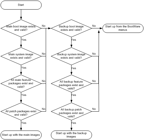
System startup process
Upon power-on, the BootWare image runs to initialize hardware, and then the startup software images run to start up the entire system, as shown in Figure 30.
Figure 30 System startup process
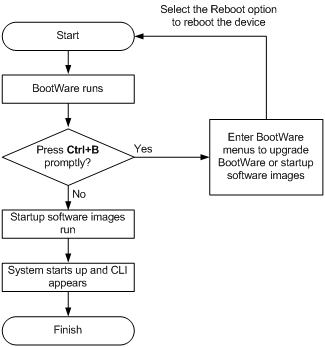
Upgrade methods
|
Upgrading method |
Software types |
Remarks |
|
Upgrading from the CLI without using ISSU |
· BootWare image · Comware images (excluding patches) |
This method is disruptive. You must reboot the entire device to complete the upgrade. |
|
Performing an ISSU |
Comware images |
The ISSU method enables a software upgrade without service interruption. As a best practice, use this method for an IRF fabric or MPU-redundant device. For more information about ISSU, see "Performing ISSU." |
|
Upgrading from the BootWare menus |
· BootWare image · Comware software images |
Use this method when the device cannot start up correctly. To use this method, first connect to the console port and power cycle the device. Then press Ctrl+B at prompt to access the BootWare menu.
Upgrade an IRF fabric from the CLI rather than the BooWare menus. The BootWare menu method increases the service downtime, because it requires that you upgrade the member devices one by one. |
This chapter only covers upgrading software from the CLI without using ISSU.
Upgrade restrictions and guidelines
Follow these restrictions and guidelines when you use the management ports on the LSXM1SUPB1 or LSXM1SUP04B1 MPU:
· If multiple management ports are connected to one remote switch, you must assign their peer ports to different VLANs on the remote switch. Login or file transfer will fail if the peer ports are in the same VLAN.
· To transfer files from the BootWare menu through TFTP or FTP, you can use only the management port M0/0/3. This interface is the forth management port on the MPU. This port is marked with a number of 3 on the card panel.
Upgrade procedure summary
To upgrade software from the CLI:
1. Download the upgrade software image file.
2. (Optional.) Preload the BootWare image to the BootWare.
If a BootWare upgrade is required, you can perform this task to shorten the subsequent upgrade time. This task helps avoid upgrade problems caused by unexpected electricity failure.
If you skip this task, the device upgrades the BootWare automatically when it upgrades the startup software images.
The BootWare image preloaded into the BootWare does not affect the device running status.
3. Specify the image file as the startup software image file.
4. If you are upgrading a standalone device, reboot the device. If you are upgrading an IRF fabric, reboot the entire IRF fabric.
5. Verify the upgrade.
Preparing for the upgrade
1. Use the display version command to verify the current BootWare image version and startup software version.
2. Use the release notes for the upgrade software version to evaluate the upgrade impact on your network and verify the following items:
¡ Software and hardware compatibility.
¡ Version and size of the upgrade software.
¡ Compatibility of the upgrade software with the current BootWare image and startup software image.
3. Use the dir command to verify that both MPUs (in standalone mode) or all MPUs (in IRF mode) have sufficient storage space for the upgrade images. If the storage space is not sufficient, delete unused files by using the delete command. For more information, see "Managing the file system."
4. Configure FTP or TFTP settings.
5. In standalone mode, download the upgrade image file to the root directory of the flash memory on the active MPU. In IRF mode, download the file to the root directory of the flash memory on the global active MPU. If the flash memory is partitioned, save the file to the root directory of the first partition.
For more information about FTP and TFTP, see "Configuring FTP" and "Configuring TFTP."
Preloading the BootWare image to BootWare
|
Step |
Command |
Remarks |
|
1. Enter system view. |
system-view |
N/A |
|
2. (Optional.) Enable BootWare image validity check. |
bootrom-update security-check enable |
By default, this function is enabled. This function examines the image for wrong file type, file corruption, and hardware incompatibility. As a best practice, enable it to ensure a successful upgrade. |
|
3. Return to user view. |
quit |
N/A |
|
4. (Optional.) Back up the current BootWare image in the Normal area of BootWare to the Backup area. |
·
In standalone mode: ·
In IRF mode: |
Back up the BootWare image for a future version rollback or image restoration. |
|
5. Load the upgrade BootWare image to the Normal area of BootWare. |
·
In standalone mode: ·
In IRF mode: |
Specify the downloaded software image file for the file-url argument. The new BootWare image takes effect at a reboot. |
Specifying startup images and completing the upgrade
In standalone mode
You can specify startup images for the MPUs in bulk, or one by one.
Specifying startup images for all MPUs in bulk
Perform this task in user view.
To specify startup images and complete the upgrade in standalone mode:
|
Step |
Command |
Remarks |
|
1. Specify main or backup startup images for all MPUs. |
·
Method 1: ·
Method 2: |
Make sure the following filename format requirements are met: · If method 1 is used, the file name must use the storage-medium:/base-filename.ipe format, for example, flash:/startup.ipe. · If method 2 is used, all file names must use the storage-medium:/base-filename.bin format, for example, flash:/startup-boot.bin. |
|
2. Save the running configuration. |
save |
This step ensures that any configuration you have made can survive a reboot. |
|
3. Reboot the device. |
reboot |
At startup, the MPUs read the preloaded BootWare image to RAM and load the startup images. |
|
4. (Optional.) Verify the software image settings. |
display boot-loader [ slot slot-number ] |
Verify that the current software images are the same as the startup software images. |
Specifying startup images for MPUs one by one
Perform this task in user view.
To specify startup images and complete the upgrade in standalone mode:
|
Step |
Command |
Remarks |
|
1. Specify the main or backup startup images for the active MPU. |
·
Method 1: ·
Method 2: |
Make sure the following filename format requirements are met: · If method 1 is used, the file name must use the storage-medium:/base-filename.ipe format, for example, flash:/startup.ipe. · If method 2 is used, all file names must use the storage-medium:/base-filename.bin format, for example, flash:/startup-boot.bin. |
|
2. Specify the main or backup startup images for the standby MPU. |
·
Method 1: ·
Method 2: ·
Method 3: · Method 4: See "Enabling software synchronization from the active MPU to the standby MPU at startup." |
When you use method 3, make sure you understand the following requirements and upgrade results: · If the active MPU started up with main startup images, its main startup images are synchronized to the standby MPU. This synchronization occurs regardless of whether any change has occurred to this set of startup images. · If the active MPU started up with backup startup images, its backup startup images are synchronized to the standby MPU. This synchronization occurs regardless of whether any change has occurred to this set of startup images. · Startup image synchronization will fail if any software image being synchronized is corrupted or is not available. |
|
3. Save the running configuration. |
save |
This step ensures that any configuration you have made can survive a reboot. |
|
4. Reboot the device. |
reboot |
At startup, the MPUs read the preloaded BootWare image to RAM and load the startup images. |
|
5. (Optional.) Verify the software image settings. |
display boot-loader [ slot slot-number ] |
Verify that the current software images are the same as the startup software images. |
In IRF mode
You can specify startup images for the MPUs in bulk, or one by one.
Specifying startup images for all MPUs in bulk
Perform this task in user view.
To specify startup images and complete the upgrade in IRF mode:
|
Step |
Command |
Remarks |
|
1. Specify the main or backup startup images for all MPUs in the IRF fabric. |
·
Method 1: ·
Method 2: |
Make sure the following filename format requirements are met: · If method 1 is used, the file name must use the storage-medium:/base-filename.ipe format, for example, flash:/startup.ipe. · If method 2 is used, all file names must use the storage-medium:/base-filename.bin format, for example, flash:/startup-boot.bin. |
|
2. Save the running configuration. |
save |
This step ensures that any configuration you have made can survive a reboot. |
|
3. Reboot the IRF fabric. |
reboot |
At startup, the MPUs read the preloaded BootWare image to RAM and load the startup images in the file. |
|
4. (Optional.) Verify the software image settings. |
display boot-loader [ chassis chassis-number [ slot slot-number ] ] |
Verify that the current software images are the same as the startup software images. |
Specifying startup images for all MPUs one by one
Perform this task in user view.
To specify startup images and complete the upgrade in IRF mode:
|
Step |
Command |
Remarks |
|
1. Specify the main or backup startup images for the global active MPU. |
·
Method 1: ·
Method 2: |
Make sure the following filename format requirements are met: · If method 1 is used, the file name must use the storage-medium:/base-filename.ipe format, for example, flash:/startup.ipe. · If method 2 is used, all file names must use the storage-medium:/base-filename.bin format, for example, flash:/startup-boot.bin. |
|
2. Specify the main startup images for each standby MPU in the IRF fabric. |
·
Method 1: ·
Method 2: ·
Method 3: |
When you use method 3, make sure you understand the following requirements and upgrade results: · If the active MPU started up with main startup images, its main startup images are synchronized to the standby MPU. This synchronization occurs regardless of whether any change has been made to this set of startup images. · If the active MPU started up with backup startup images, its backup startup images are synchronized to the standby MPU. This synchronization occurs regardless of whether any change has been made to this set of startup images. · Startup image synchronization will fail if any software image being synchronized is corrupted or is not available. |
|
3. Save the running configuration. |
save |
This step ensures that any configuration you have made can survive a reboot. |
|
4. Reboot the IRF fabric. |
reboot |
At startup, the MPUs read the preloaded BootWare image to RAM and load the startup images in the file. |
|
5. (Optional.) Verify the software image settings. |
display boot-loader [ chassis chassis-number [ slot slot-number ] ] |
Verify that the current software images are the same as the startup software images. |
Restoring or downgrading the BootWare image
To restore or downgrade the BootWare image for a card, make sure you have used the bootrom backup command or the bootrom read command to back up the image to the Backup area of BootWare.
Before performing a downgrade, also verify software compatibility.
Perform this task in user view.
To restore or downgrade the BootWare image:
|
Step |
Command |
Remarks |
|
1. Replace the BootWare image in the Normal area of BootWare. |
·
In standalone mode: ·
In IRF mode: |
N/A |
|
2. Reboot the device or the entire IRF fabric. |
reboot |
At startup, the system runs the new BootWare image to complete the restoration or downgrade. |
Enabling software synchronization from the active MPU to the standby MPU at startup
This feature is available only when the device is operating in standalone mode. To synchronize software from the global active MPU to other MPUs on an IRF fabric, use the irf auto-update enable command. For more information about software auto-update, see IRF Configuration Guide.
When the standby MPU starts up, this feature examines its startup software images for version inconsistency with the current software images on the active MPU.
If the software versions are different, the standby MPU performs the following operations:
1. Copies the current software images of the active MPU.
2. Specifies the images as startup software images.
3. Reboots with these images.
|
|
IMPORTANT: To ensure a successful synchronization in a multi-user environment, prevent users from rebooting or swapping MPUs during the software synchronization process. You can configure the information center to output the synchronization status to configuration terminals (see Network Management and Monitoring Configuration Guide). |
To enable software synchronization from the active MPU to the standby MPU at startup:
|
Step |
Command |
Remarks |
|
1. Enter system view. |
system-view |
N/A |
|
2. Enable startup software version check for the standby MPU. |
undo version check ignore |
By default, startup software version check is enabled. |
|
3. Enable software auto-update for the standby MPU. |
version auto-update enable |
By default, software version auto-update is enabled. |
Displaying and maintaining software image settings
Execute display commands in any view.
|
Task |
Command |
|
Display current software images and startup software images (in standalone mode). |
display boot-loader [ slot slot-number ] |
|
Display current software images and startup software images (in IRF mode). |
display boot-loader [ chassis chassis-number [ slot slot-number ] ] |
Software upgrade example (for standalone mode)
Network requirements
The device has two MPUs: one active MPU in slot 17 and one standby MPU in slot 16.
Use the file S12500X.ipe to upgrade software images for the device.
Figure 31 Network diagram
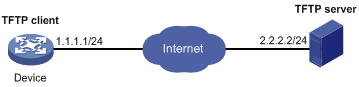
Configuration procedure
# Configure IP addresses and routes. Make sure the device and the TFTP server can reach each other. (Details not shown.)
# Configure TFTP settings on both the device and the TFTP server. (Details not shown.)
# Display information about the current software images.
<Sysname> display version
# Use TFTP to download the image file S12500X.ipe from the TFTP server to the root directory of the flash memory on the active MPU.
<Sysname> tftp 2.2.2.2 get S12500X.ipe
# (Optional.) Back up the image file to S12500X-backup.ipe. Skip this step if the flash does not have sufficient space.
<Sysname> copy S12500X.ipe S12500X-backup.ipe
# Specify S12500X.ipe as the main startup image file for both MPUs.
<Sysname> boot-loader file flash:/S12500X.ipe slot 17 main
<Sysname> boot-loader file flash:/S12500X.ipe slot 16 main
# Specify S12500X-backup.ipe as the backup startup image file for both MPUs.
<Sysname> boot-loader file flash:/S12500X-backup.ipe slot 17 backup
<Sysname> boot-loader file flash:/S12500X-backup.ipe slot 16 backup
# Verify the startup image settings.
<Sysname> display boot-loader
# Reboot the device to complete the upgrade.
<Sysname> reboot
# Verify that the device is running the correct software.
<Sysname> display version
Software upgrade example (for IRF mode)
Network requirements
Use the file S12500X.ipe to upgrade software images for the IRF fabric in Figure 32.
Each IRF member device has two MPUs: one in slot 17 and one in slot 16. The global active MPU is in slot 17 on the master device.
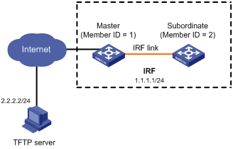
Configuration procedure
# Configure IP addresses and routes. Make sure the device and the TFTP server can reach each other. (Details not shown.)
# Complete TFTP settings on both the device and the TFTP server. (Details not shown.)
# Display information about the current software images.
<Sysname> display version
# Use TFTP to download the image file S12500X.ipe from the TFTP server to the root directory of the flash memory on the global active MPU.
<Sysname> tftp 2.2.2.2 get S12500X.ipe
# (Optional.) Back up the image file to S12500X-backup.ipe on the global active MPU. Skip this step if the flash does not have sufficient space.
<Sysname> copy S12500X.ipe S12500X-backup.ipe
# Specify S12500X.ipe as the main startup image file for all MPUs.
<Sysname> boot-loader file flash:/S12500X.ipe chassis 1 slot 17 main
<Sysname> boot-loader file flash:/S12500X.ipe chassis 1 slot 16 main
<Sysname> boot-loader file flash:/S12500X.ipe chassis 2 slot 17 main
<Sysname> boot-loader file flash:/S12500X.ipe chassis 2 slot 16 main
# Specify S12500X-backup.ipe as the backup startup image file for all MPUs.
<Sysname> boot-loader file flash:/S12500X-backup.ipe chassis 1 slot 17 backup
<Sysname> boot-loader file flash:/S12500X-backup.ipe chassis 1 slot 16 backup
<Sysname> boot-loader file flash:/S12500X-backup.ipe chassis 2 slot 17 backup
<Sysname> boot-loader file flash:/S12500X-backup.ipe chassis 2 slot 16 backup
# Verify the startup image settings.
<Sysname> display boot-loader
# Reboot the IRF fabric to complete the upgrade.
<Sysname> reboot
# Verify that the IRF fabric is running the correct software.
<Sysname> display version
Performing an ISSU
ISSU is available only for two-chassis IRF fabrics.
Overview
The In-Service Software Upgrade (ISSU) feature provides the ability to upgrade software with a minimum amount of downtime.
ISSU is implemented on the basis of the following design advantages:
· Separation of service features from basic functions—Device software is segmented into boot, system, and feature images. The images can be upgraded individually.
· Independence between service features—Features run independently. One feature can be added or upgraded without affecting the operation of the system or other features.
· Support for hotfix—Patch images are available to fix system bugs without a system reboot.
· Hardware redundancy—On a dual-MPU device or a multichassis IRF fabric, one MPU or member device can be upgraded while other MPUs or member devices are providing services.
For more information about images, see "Upgrading software."
ISSU flow chart
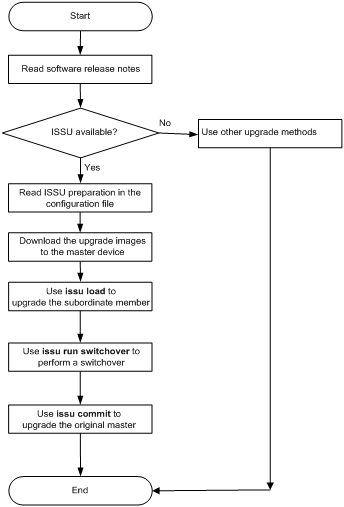
ISSU method
The system reboots MPUs for an ISSU. If an ISSU requires both the active and standby MPUs to reboot, upgrade the standby MPU first.
Preparing for ISSU
For a successful ISSU, make sure all the preparation requirements are met.
Identifying availability of ISSU
1. Use the release notes to verify that ISSU is supported between the current software version and the new software version.
2. Verify that the system is a two-chassis IRF fabric.
Verifying the device operating status
Verify the following items:
· Use the display device command to verify that no member devices are in Fault state.
· Use the display mdc command to verify that all MDCs are in active state.
· Use the switchto mdc command to verify that no automatic configuration process is in progress. If the message Automatic configuration is running, press CTRL_C or CTRL_D to break. appears, an automatic configuration process is in progress. To perform an ISSU, wait for the process to complete or abort the process. For more information about automatic configuration, see "Using automatic configuration."
Preparing the upgrade images
1. Use the dir command to verify that all MPUs have sufficient storage space for the upgrade images. If the storage space is not sufficient, delete unused files by using the delete /unreserved file-url command. If the files to be deleted will be used, back up the files before deleting them. You will be unable to restore a deleted file if the /unreserved keyword is used. For more information, see "Managing the file system."
2. (Optional.) To use the management ports for file transfer, perform the following steps if the IRF fabric uses LSXM1SUPB1 or LSXM1SUP04B1 MPUs:
a. Identify whether multiple management ports are connected to the same remote switch.
b. If multiple management ports are connected to the same remote switch, assign the peer ports to different VLANs on the remote switch. File transfer will fail if the peer ports are in the same VLAN.
3. Use FTP or TFTP to transfer upgrade image files to the root directory of the flash memory on the global active MPU. When you upgrade a standby MPU, the system automatically copies the files to the standby MPU. If an existing file on the standby MPU uses the same name as a copied file, the system prompts for your confirmation.
Verifying network and feature status
For a successful ISSU, make sure the network is stable.
For service continuity during ISSU, configure the following feature settings:
|
Feature |
Setting requirements |
|
GR/NSR |
Enable GR or NSR for protocols including LDP, RSVP, OSPF, ISIS, and BGP. |
|
BFD |
Disable BFD for protocols including LDP, RSVP, OSPF, ISIS, RIP, BGP, VRRP, and NQA. |
|
Ethernet link aggregation |
Use the long LACP timeout interval (the lacp period short command is not configured) on all member ports in dynamic aggregation groups. |
|
IRF |
Configure the irf mac-address persistent always command if the bridge MAC address is the MAC address of the device for which you want to execute the issu load command. |
Understanding ISSU guidelines
During an ISSU, use the following guidelines:
· In a multiuser environment, make sure no other administrators access the device while you are performing the ISSU.
· Do not perform any of the following tasks during an ISSU:
¡ Reboot, install, or remove any cards.
¡ Execute any commands that are not for ISSU.
¡ Modify, delete, or rename any image files.
After an ISSU, you must log in to the device again before you can configure the device.
Logging in to the device through the console port
Log in to the device through the console port after you finish all the preparation tasks and read all the ISSU guidelines.
If you use Telnet or SSH, you might be disconnected from the device before the ISSU is completed.
Adjusting and saving the running configuration
1. Identify the configured commands that the new software version do not support and remove the configuration.
2. Use the save command to save the running configuration.
Upgrading the boot and system images
When you use the issu series commands to install or upgrade the software of MPUs, the device automatically install or upgrade the software of the service cards as needed. You do not need to install or upgrade the software of the service cards separately.
ISSU for a multichassis IRF fabric should be performed as per member in two steps: first upgrade the subordinate member, and then upgrade the master.
The device supports version rollback.
· Manual rollback—Before executing the issu commit command to complete an ISSU process, you can use the issu rollback command to roll back to the original software images.
· Automatic rollback—When you execute the issu run switchover command, the system starts the automatic rollback timer. If you do not execute the issu accept or issu commit command before this timer expires, the system automatically rolls back to the original software images.
To perform an ISSU:
|
Step |
Command |
Remarks |
|
1. Enter system view. |
system-view |
N/A |
|
2. Set the automatic rollback timer. |
issu rollback-timer minutes |
By default, the automatic rollback timer is set to 45 minutes. |
|
3. Exit to user view. |
quit |
N/A |
|
4. (Optional.) Decompress an .ipe file. |
install add ipe-filename medium-name: |
N/A |
|
5. Load the upgrade images as the main startup software images on the subordinate member device. |
·
Method 1: ·
Method 2: |
Specify the member ID of the subordinate member for the chassis-number argument. |
|
6. To complete the ISSU process on the subordinate device, perform a master/subordinate switchover. |
issu run switchover |
N/A |
|
7. Accept the upgrade and delete the automatic rollback timer. |
issu accept |
N/A |
|
8. (Optional.) Roll back to the original software images. |
issu rollback |
N/A |
|
9. Upgrade the original master to complete the ISSU. |
issu commit chassis chassis-number |
N/A |
Installing patch images
Perform this task in user view.
To install patch images:
|
Step |
Command |
Remarks |
|
1. Activate patch images. |
·
In standalone mode: ·
In IRF mode: |
N/A |
|
2. Commit the software changes. |
install commit |
Patch images run in memory after being activated. For activated images to run after a reboot, you must commit the software changes. |
Uninstalling patch images
Perform this task in user view.
To uninstall patch images:
|
Step |
Command |
Remarks |
|
1. Deactivate patch images. |
·
In standalone mode: ·
In IRF mode: |
N/A |
|
2. Commit the software changes. |
install commit |
Patch images stop running in memory after being deactivated. To prevent deactivated images from running after a reboot, you must commit the software change. Uninstalled patch images are still saved on the storage medium. |
Displaying and maintaining ISSU
Execute display commands in any view.
|
Task |
Command |
|
Display active software images. |
·
In standalone mode: ·
In IRF mode: |
|
Display main startup software images. |
·
In standalone mode: ·
In IRF mode: |
|
Display the software images included in an .ipe file. |
display install ipe-info ipe-filename |
|
Display software image file information. |
display install package { filename | all } [ verbose ] |
|
Display automatic rollback timer information. |
display issu rollback-timer |
|
Display ISSU status information. |
display issu state |
|
Display version compatibility information. |
display version comp-matrix |
ISSU example
Upgrade requirement
As shown in Figure 34, the IRF fabric has two members. Each member has one MPU in slot 16 (active MPU) and one MPU in slot 17 (standby MPU).
Upgrade the boot and system images from R0201 to R0202.
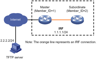
Upgrade procedure
# Download the .ipe file that contains the R0202 boot and system images from the TFTP server.
<Sysname> tftp 2.2.2.2 get version-r0202.ipe
% Total % Received % Xferd Average Speed Time Time Time Current
Dload Upload Total Spent Left Speed
100 256k 100 256k 0 0 764k 0 --:--:-- --:--:-- --:--:-- 810k
# Display active software images.
<Sysname> display install active
Active packages on chassis 1 slot 16:
flash:/boot-r0201.bin
flash:/system-r0201.bin
Active packages on chassis 1 slot 17:
flash:/boot-r0201.bin
flash:/system-r0201.bin
Active packages on chassis 2 slot 16:
flash:/boot-r0201.bin
flash:/system-r0201.bin
Active packages on chassis 2 slot 17:
flash:/boot-r0201.bin
flash:/system-r0201.bin
# Upgrade the boot and system images on the subordinate member.
<Sysname> issu load file ipe flash:/version-r0202.ipe chassis 2
This operation will delete the rollback point information for the previous upgrade and maybe get unsaved configuration lost. Continue? [Y/N]:y
Verifying image file flash:/version-r0202.ipe on slot 16.................Done.
Decompressing file BOOT-R0202.bin to flash:/BOOT-R0202.bin.............Done.
Decompressing file SYSTEM-R0202.bin to flash:/SYSTEM-R0202.bin...........Done.
Decompression completed.
Do you want to delete flash:/version-r0202.ipe now? [Y/N]:n
Upgrade summary according to following table:
flash:/BOOT-R0202.bin
Running Version New Version
Release 0201 Release 0202
flash:/SYSTEM-R0202.bin
Running Version New Version
Release 0201 Release 0202
Chassis Slot Upgrade Way
2 16 Reboot
2 17 Reboot
Upgrading software images to compatible versions. Continue? [Y/N]:y
# Perform a master/subordinate switchover.
<Sysname> issu run switchover
Upgrade summary according to following table:
flash:/BOOT-R0202.bin
Running Version New Version
Release 0201 Release 0202
flash:/SYSTEM-R0202.bin
Running Version New Version
Release 0201 Release 0202
Chassis Slot Switchover Way
2 16 Global active standby MPU switchover
Upgrading software images to compatible versions. Continue? [Y/N]:y
# Upgrade the original master.
<Sysname> issu commit chassis 1
flash:/BOOT-r0202.bin
Running Version New Version
Release 0201 Release 0202
flash:/SYSTEM-r0202.bin
Running Version New Version
Release 0201 Release 0202
Chassis Slot Upgrade Way
1 16 Reboot
1 17 Reboot
Upgrading software images to compatible versions. Continue? [Y/N]:y
# Verify that both members are running the new boot and system images.
<Sysname> display install active
Active packages on chassis 1 slot 16:
flash:/boot-r0202.bin
flash:/system-r0202.bin
Active packages on chassis 1 slot 17:
flash:/boot-r0202.bin
flash:/system-r0202.bin
Active packages on chassis 2 slot 16:
flash:/boot-r0202.bin
flash:/system-r0202.bin
Active packages on chassis 2 slot 17:
flash:/boot-r0202.bin
flash:/system-r0202.bin
Managing the device
This chapter describes how to monitor the operating status of the device, configure the running parameters (such as the device name, system time, and the temperature alarm thresholds), and reboot the device.
You can perform the configuration tasks in this chapter in any order.
Configuring the device name
A device name, or "hostname," identifies a device in a network and is used in CLI view prompts. For example, if the device name is Sysname, the user view prompt is <Sysname>.
|
Step |
Command |
Remarks |
|
1. Enter system view. |
system-view |
N/A |
|
2. Configure the device name. |
sysname sysname |
By default, the device name is H3C. |
Configuring the system time
Correct system time is essential to network management and communication. Configure the system time correctly before you run the device on the network.
Specifying the system time source
The device can use one of the following system time sources:
· None—Local system time. If you specify this time source for the device, you must set the system time as described in "Setting the system time."
· NTP—NTP time source. When the device uses the NTP time source, you cannot change the system time manually. For more information about NTP, see Network Management and Monitoring Configuration Guide.
To specify the system time source:
|
Step |
Command |
Remarks |
|
1. Enter system view. |
system-view |
N/A |
|
2. Specify the system time source. |
clock protocol { none | ntp mdc mdc-id } |
By default, the device uses the NTP time source specified on the default MDC. If you execute this command multiple times, the most recent configuration takes effect. |
Setting the system time
The system time is determined by the UTC time, local time zone, and daylight saving time. You can use the display clock command to view the system time.
If you configure both the system time and NTP or SNTP, the device uses the time synchronized from the NTP server as the system time. For more information about NTP and SNTP, see Network Management and Monitoring Configuration Guide.
Powering off or using the reboot command to reboot an S12500-X or S12500X-AF switch does not affect the system time.
|
Step |
Command |
Remarks |
|
1. Set the UTC time. |
clock datetime time date |
By default, the factory default UTC time is used. Use this command in user view. |
|
2. Enter system view. |
system-view |
N/A |
|
3. Set the local time zone. |
clock timezone zone-name { add | minus } zone-offset |
The default local time zone is the UTC time zone. |
|
4. Set the daylight saving time. |
clock summer-time name start-time start-date end-time end-date add-time |
By default, daylight saving time is disabled. |
Enabling displaying the copyright statement
The device displays the copyright statement in the following situations:
· When a Telnet or SSH user logs in.
· When a console user quits user view (the device automatically tries to restart the console session).
You can disable or enable displaying copyright statement as needed. The following is a sample copyright statement:
******************************************************************************
* Copyright (c) 2004-2014 Hangzhou H3C Tech. Co., Ltd. All rights reserved. *
* Without the owner's prior written consent, *
* no decompiling or reverse-engineering shall be allowed. *
******************************************************************************
To enable displaying the copyright statement:
|
Step |
Command |
Remarks |
|
1. Enter system view. |
system-view |
N/A |
|
2. Enable displaying the copyright statement. |
copyright-info enable |
By default, this feature is enabled. |
Configuring banners
Banners are messages that the system displays when a user logs in.
Banner types
The system supports the following banners:
· Legal banner—Appears after the copyright statement. To continue login, the user must enter Y or press Enter. To quit the process, the user must enter N. Y and N are case insensitive.
· Message of the Day (MOTD) banner—Appears after the legal banner and before the login banner. Support for this banner depends on the device model.
· Login banner—Appears only when password or scheme authentication is configured.
· Shell banner—Appears for all login users.
Banner input methods
You can configure a single-line banner or a multi-line banner:
· Single-line banner.
A single-line banner must be input in the same line as the command. The start and end delimiters for the banner can be any printable character, but they must be the same and must not be included in the banner. The input text, including the command keywords and the delimiters, cannot exceed 510 characters. Do not press Enter before you input the end delimiter.
For example, you can configure the shell banner "Have a nice day." as follows:
<System> system-view
[System] header shell %Have a nice day.%
· Multi-line banner.
A multi-line banner can be up to 2000 characters, including the start and end delimiters. To input a multi-line banner, use one of the following methods:
¡ Method 1—Press Enter after the last command keyword. At the system prompt, enter the banner and end the last line with the delimiter character %. For example, you can configure the banner "Have a nice day. Please input the password." as follows:
<System> system-view
[System] header shell
Please input banner content, and quit with the character '%'.
Have a nice day.
Please input the password.%
¡ Method 2—After you type the last command keyword, type any single printable character as the start delimiter for the banner and press Enter. At the system prompt, type the banner and end the last line with the same delimiter. For example, you can configure the banner "Have a nice day. Please input the password." as follows:
<System> system-view
[System] header shell A
Please input banner content, and quit with the character 'A'.
Have a nice day.
Please input the password.A
¡ Method 3—After you type the last command keyword, type the start delimiter and part of the banner and press Enter. At the system prompt, enter the rest of the banner and end the last line with the same delimiter. For example, you can configure the banner "Have a nice day. Please input the password." as follows:
<System> system-view
[System] header shell AHave a nice day.
Please input banner content, and quit with the character 'A'.
Please input the password.
A
Configuration procedure
To configure banners:
|
Step |
Command |
Remarks |
|
1. Enter system view. |
system-view |
By default, no banner is configured. |
|
2. Configure the legal banner. |
header legal text |
By default, no banner is configured. |
|
3. Configure the MOTD banner. |
header motd text |
By default, no banner is configured. |
|
4. Configure the login banner. |
header login text |
By default, no banner is configured. |
|
5. Configure the shell banner. |
header shell text |
By default, no banner is configured. |
Setting the system operating mode
|
|
CAUTION: Perform this task with caution. Changing the system operating mode might cause configuration loss. |
The device can operate in the following modes:
· advance—Advanced mode.
· standard—Standard mode.
In different operating modes, the device supports different features. For example:
· The device supports EVI and FCoE only when it operates in advanced mode. For more information about EVI, see EVI Configuration Guide. For more information about FCoE, see FCoE Configuration Guide.
· The device supports SPBM only when it operates in enhanced Layer 2 mode. For more information about SPBM, see SPB Configuration Guide.
· The device supports VXLAN only when it operates in standard mode. For more information about VXLAN, see VXLAN Configuration Guide.
To set the system operating mode:
|
Step |
Command |
Remarks |
|
1. Enter system view. |
system-view |
N/A |
|
2. Set the system operating mode. |
system-working-mode { advance | bridgee | standard } |
By default, the device operates in standard mode. The bridgee keyword is available in Release 1138P01 and later versions. For an operating mode change to take effect, you must perform the following tasks: · Save the running configuration to the next-startup configuration file. · Delete the.mdb file for the next-startup configuration file. · Reboot the device. |
Setting the TCAM operating mode
|
|
IMPORTANT: This feature is available for the FE card in Release 1138P01 and later versions. |
The FE card provides the device with an extended memory space, which is the ternary content addressable memory (TCAM). The TCAM can operate in the following modes:
· acl—Stores Layer 2 ACLs and IPv4 ACLs to extend the storage capacity for the ACLs.
· normal—Does not provide extended memory space for the device.
· routing—Stores ARP entries and IPv4 routing entries to extend the storage capacity for the entries.
For a TCAM operating mode change to take effect, perform the following tasks:
· Save the running configuration to the next-startup configuration file.
· Delete the .mdb binary file for the next-startup configuration file.
· Reboot the device.
To set the TCAM operating mode:
|
Step |
Command |
Remarks |
|
1. Enter system view. |
system-view |
N/A |
|
2. Set the TCAM operating mode. |
hardware-resource tcam { acl | normal | routing } |
By default, the TCAM operating mode is routing. |
Rebooting the device
|
|
CAUTION: · A reboot can interrupt network services. · To avoid configuration loss, use the save command to save the running configuration before a reboot. For more information about the save command, see Fundamentals Command Reference. · Before a reboot, use the display startup and display boot-loader commands to verify that you have correctly specified the startup configuration file and startup software images. If the main startup software images are corrupted or missing, you must re-specify a set of main startup software images before using the reboot command to reboot the device. Otherwise, the device cannot start up. For more information about the two display commands, see Fundamentals Command Reference. |
The following device reboot methods are available:
· Immediately reboot the device at the CLI.
· Schedule a reboot at the CLI, so the device automatically reboots at the specified time or after the specified period of time.
· Power off and then power on the device. This method might cause data loss, and is the least-preferred method.
Using the CLI, you can reboot the device from a remote host.
Configuration guidelines
Follow these guidelines when you reboot the device:
· In standalone mode, the automatic reboot configuration is canceled if an active/standby switchover occurs.
· In IRF mode, the automatic reboot configuration is effective on all member devices. If a switchover between the global active MPU and a global standby MPU occurs, the automatic reboot configuration is canceled.
· For data security, the device does not reboot while it is performing file operations.
Rebooting devices immediately at the CLI
Execute one of the following commands as appropriate in user view:
|
Task |
Command |
Remarks |
|
Reboot a card or the entire device. (In standalone mode.) |
reboot [ slot slot-number ] [ force ] |
This command is available in user view. |
|
Reboot an IRF member device or all IRF member devices. (In IRF mode.) |
reboot [ chassis chassis-number [ slot slot-number ] ] [ force ] |
This command is available in user view. |
Scheduling a device reboot
The device supports only one device reboot schedule. If you configure the scheduler reboot at or scheduler reboot delay command multiple times or configure both commands, the most recent configuration takes effect.
To schedule a reboot, execute either of the following commands in user view:
|
Task |
Command |
Remarks |
|
Specify the reboot date and time. |
scheduler reboot at time [ date ] |
By default, no reboot date or time is specified. |
|
Specify the reboot delay time. |
scheduler reboot delay time |
By default, no reboot delay time is specified. |
Scheduling a task
You can schedule the device to automatically execute a command or a set of commands without administrative interference.
You can configure a non-periodic schedule or a periodic schedule. A non-periodic schedule is not saved to the configuration file and is lost when the device reboots. A periodic schedule is saved to the startup configuration file and is automatically executed periodically.
Configuration restrictions and guidelines
Follow these restrictions and guidelines when you schedule a task:
· To make sure a task schedule can be executed as expected, reconfigure the system time or configure NTP after you reboot the device. For more information about NTP, see Network Management and Monitoring Configuration Guide.
· Make sure all commands in a schedule are compliant to the command syntax. The system does not check the syntax when you assign a command to a job.
· A schedule cannot contain any of these commands: telnet, ftp, ssh2, and monitor process.
· A schedule does not support user interaction. If a command requires a yes or no answer, the system always assumes that a Y or Yes is entered. If a command requires a character string input, the system assumes that the default character string (if any) is entered, or a null string is entered.
· A schedule is executed in the background, and no output (except for logs, traps, and debug information) is displayed for the schedule.
Configuration procedure
To configure a non-periodic schedule for the device:
|
Step |
Command |
Remarks |
|
1. Enter system view. |
system-view |
N/A |
|
2. Create a job. |
scheduler job job-name |
By default, no job exists. |
|
3. Assign a command to the job. |
command id command |
By default, no command is assigned to a job. You can assign multiple commands to a job. A command with a smaller ID will be executed first. |
|
4. Exit to system view. |
quit |
N/A |
|
5. Create a schedule. |
scheduler schedule schedule-name |
By default, no schedule exists. |
|
6. Assign a job to a schedule. |
job job-name |
By default, no job is assigned to a schedule. You can assign multiple jobs to a schedule. The jobs will be executed concurrently. |
|
7. Assign user roles to the schedule. |
user-role role-name |
By default, a schedule has the user role of the schedule creator. You can assign up to 64 user roles to a schedule. A command in a schedule can be executed if it is permitted by one or more user roles of the schedule. |
|
8. Specify an execution time table for the non-periodic schedule. |
·
Specify the execution date
and time: ·
Specify the execution days
and time: ·
Specify the execution delay time: |
Configure one command as required. By default, no execution time is specified for a schedule. Executing commands clock datetime, clock summer-time, and clock timezone does not change the execution time table that is already configured for a schedule. |
To configure a periodic schedule for the device:
|
Step |
Command |
Remarks |
|
1. Enter system view. |
system-view |
N/A |
|
2. Create a job. |
scheduler job job-name |
By default, no job exists. |
|
3. Assign a command to the job. |
command id command |
By default, no command is assigned to a job. You can assign multiple commands to a job. A job with a smaller ID will be executed first. |
|
4. Exit to system view. |
quit |
N/A |
|
5. Create a schedule. |
scheduler schedule schedule-name |
By default, no schedule exists. |
|
6. Assign a job to a schedule. |
job job-name |
By default, no job is assigned to a schedule. You can assign multiple jobs to a schedule. The jobs will be executed concurrently. |
|
7. Assign user roles to the schedule. |
user-role role-name |
By default, a schedule has the user role of the schedule creator. You can assign up to 64 user roles to a schedule. A command in a schedule can be executed if it is permitted by one or more user roles of the schedule. |
|
8. Specify an execution time table for the periodic schedule. |
·
Execute the schedule at an interval from the specified time on: ·
Execute the schedule at the specified time on
every specified day in a month or week: |
Configure either command. By default, no execution time is specified for a schedule. Executing commands clock datetime, clock summer-time, and clock timezone does not change the execution time table that is already configured for a schedule. |
Schedule configuration example
Network requirements
To save energy, configure the device to enable interfaces FortyGigE 1/0/1 and FortyGigE 1/0/2 at 8:00 a.m. every Monday through Friday and disable the interfaces at 18:00 every Monday through Friday.
Figure 35 Network diagram
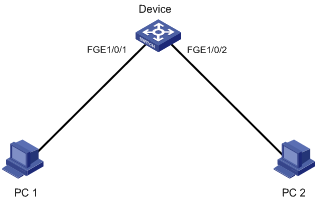
Scheduling procedure
# Enter system view.
<Sysname> system-view
# Configure a job for disabling interface FortyGigE 1/0/1.
[Sysname] scheduler job shutdown-FortyGigE1/0/1
[Sysname-job-shutdown-FortyGigE1/0/1] command 1 system-view
[Sysname-job-shutdown-FortyGigE1/0/1] command 2 interface fortygige 1/0/1
[Sysname-job-shutdown-FortyGigE1/0/1] command 3 shutdown
[Sysname-job-shutdown-FortyGigE1/0/1] quit
# Configure a job for enabling interface FortyGigE 1/0/1.
[Sysname] scheduler job start-FortyGigE1/0/1
[Sysname-job-start-FortyGigE1/0/1] command 1 system-view
[Sysname-job-start-FortyGigE1/0/1] command 2 interface fortygige 1/0/1
[Sysname-job-start-FortyGigE1/0/1] command 3 undo shutdown
[Sysname-job-start-FortyGigE1/0/1] quit
# Configure a job for disabling interface FortyGigE 1/0/2.
[Sysname] scheduler job shutdown-FortyGigE1/0/2
[Sysname-job-shutdown-FortyGigE1/0/2] command 1 system-view
[Sysname-job-shutdown-FortyGigE1/0/2] command 2 interface fortygige 1/0/2
[Sysname-job-shutdown-FortyGigE1/0/2] command 3 shutdown
[Sysname-job-shutdown-FortyGigE1/0/2] quit
# Configure a job for enabling interface FortyGigE 1/0/2.
[Sysname] scheduler job start-FortyGigE1/0/2
[Sysname-job-start-FortyGigE1/0/2] command 1 system-view
[Sysname-job-start-FortyGigE1/0/2] command 2 interface fortygige 1/0/2
[Sysname-job-start-FortyGigE1/0/2] command 3 undo shutdown
[Sysname-job-start-FortyGigE1/0/2] quit
# Configure a periodic schedule for enabling the interfaces at 8:00 a.m. every Monday through Friday.
[Sysname] scheduler schedule START-pc1/pc2
[Sysname-schedule-START-pc1/pc2] job start-FortyGigE1/0/1
[Sysname-schedule-START-pc1/pc2] job start-FortyGigE1/0/2
[Sysname-schedule-START-pc1/pc2] time repeating at 8:00 week-day mon tue wed thu fri
[Sysname-schedule-START-pc1/pc2] quit
# Configure a periodic schedule for disabling the interfaces at 18:00 every Monday through Friday.
[Sysname] scheduler schedule STOP-pc1/pc2
[Sysname-schedule-STOP-pc1/pc2] job shutdown-FortyGigE1/0/1
[Sysname-schedule-STOP-pc1/pc2] job shutdown-FortyGigE1/0/2
[Sysname-schedule-STOP-pc1/pc2] time repeating at 18:00 week-day mon tue wed thu fri
[Sysname-schedule-STOP-pc1/pc2] quit
Verifying the scheduling
# Display the configuration information of all jobs.
[Sysname] display scheduler job
Job name: shutdown-FortyGigE1/0/1
system-view
interface fortygige 1/0/1
shutdown
Job name: shutdown-FortyGigE1/0/2
system-view
interface fortygige 1/0/2
shutdown
Job name: start-FortyGigE1/0/1
system-view
interface fortygige 1/0/1
undo shutdown
Job name: start-FortyGigE1/0/2
system-view
interface fortygige 1/0/2
undo shutdown
# Display the schedule information.
[Sysname] display scheduler schedule
Schedule name : START-pc1/pc2
Schedule type : Run on every Mon Tue Wed Thu Fri at 08:00:00
Start time : Wed Sep 28 08:00:00 2011
Last execution time : Wed Sep 28 08:00:00 2011
Last completion time : Wed Sep 28 08:00:03 2011
Execution counts : 1
-----------------------------------------------------------------------
Job name Last execution status
start-FortyGigE1/0/1 Successful
start-FortyGigE1/0/2 Successful
Schedule name : STOP-pc1/pc2
Schedule type : Run on every Mon Tue Wed Thu Fri at 18:00:00
Start time : Wed Sep 28 18:00:00 2011
Last execution time : Wed Sep 28 18:00:00 2011
Last completion time : Wed Sep 28 18:00:01 2011
Execution counts : 1
-----------------------------------------------------------------------
Job name Last execution status
shutdown-FortyGigE1/0/1 Successful
shutdown-FortyGigE1/0/2 Successful
# Display schedule log information.
[Sysname] display scheduler logfile
Job name : start-FortyGigE1/0/1
Schedule name : START-pc1/pc2
Execution time : Wed Sep 28 08:00:00 2011
Completion time : Wed Sep 28 08:00:02 2011
--------------------------------- Job output -----------------------------------
<Sysname>system-view
System View: return to User View with Ctrl+Z.
[Sysname]interface fortygige 1/0/1
[Sysname-FortyGigE1/0/1]undo shutdown
Job name : start-FortyGigE1/0/2
Schedule name : START-pc1/pc2
Execution time : Wed Sep 28 08:00:00 2011
Completion time : Wed Sep 28 08:00:02 2011
--------------------------------- Job output -----------------------------------
<Sysname>system-view
System View: return to User View with Ctrl+Z.
[Sysname]interface fortygige 1/0/2.
[Sysname-FortyGigE1/0/2]undo shutdown
Job name : shutdown-FortyGigE1/0/1
Schedule name : STOP-pc1/pc2
Execution time : Wed Sep 28 18:00:00 2011
Completion time : Wed Sep 28 18:00:01 2011
--------------------------------- Job output -----------------------------------
<Sysname>system-view
System View: return to User View with Ctrl+Z.
[Sysname]interface fortygige 1/0/1
[Sysname-FortyGigE1/0/1]shutdown
Job name : shutdown-FortyGigE1/0/2
Schedule name : STOP-pc1/pc2
Execution time : Wed Sep 28 18:00:00 2011
Completion time : Wed Sep 28 18:00:01 2011
--------------------------------- Job output -----------------------------------
<Sysname>system-view
System View: return to User View with Ctrl+Z.
[Sysname]interface fortygige 1/0/2
[Sysname-FortyGigE1/0/2]shutdown
Disabling password recovery capability
Password recovery capability controls console user access to the device configuration and SDRAM from BootWare menus. This feature also determines the method for handling console login password loss.
If password recovery capability is enabled, a console user can access the device configuration without authentication to configure new passwords.
If password recovery capability is disabled, console users must restore the factory-default configuration before they can configure new passwords. Restoring the factory-default configuration deletes the next-startup configuration files.
To enhance system security, disable password recovery capability.
Availability of BootWare menu options varies with the password recovery capability setting. For more information, see the release notes.
To disable password recovery capability:
|
Step |
Command |
Remarks |
|
1. Enter system view. |
system-view |
N/A |
|
2. Disable password recovery capability. |
undo password-recovery enable |
By default, password recovery capability is enabled. |
Setting the port status detection timer
To set the port status detection timer:
|
Step |
Command |
Remarks |
|
1. Enter system view. |
system-view |
N/A |
|
2. Set the port status detection timer. |
shutdown-interval time |
The default setting is 30 seconds. |
Monitoring the CPU usage
You can enable CPU usage monitoring so the system periodically samples and saves CPU usage. To examine recent CPU usage, use the display cpu-usage history command.
You can also set CPU usage thresholds. When a CPU usage threshold is reached, the device sends a trap.
To monitor the CPU usage:
|
Step |
Command |
Remarks |
|
1. Enter system view. |
system-view |
N/A |
|
2. Enable CPU usage monitoring. |
·
In standalone mode: ·
In IRF mode: |
By default, CPU usage monitoring is enabled. |
|
3. Configure the interval at which the device samples CPU usage statistics. |
·
In standalone mode: ·
In IRF mode: |
By default, the interval is 1 minute. |
|
4. Set CPU usage thresholds. |
·
In standalone mode: ·
In IRF mode: |
By default, the CPU usage threshold is 99%. |
Setting memory thresholds
To ensure correct operation and improve memory efficiency, the system monitors the memory usage and the amount of free memory space in real time.
· If the memory usage threshold is exceeded, the system generates and sends a trap.
· If a free-memory threshold is exceeded, the system generates an alarm notification or an alarm-removed notification and sends it to affected service modules or processes.
The device supports the following free-memory thresholds:
¡ Normal state threshold.
¡ Minor alarm threshold.
¡ Severe alarm threshold.
¡ Critical alarm threshold.
Table 14 and Figure 36 show how the device generates notifications based on the free-memory thresholds.
Table 14 Memory alarm notifications and memory alarm-removed notifications
|
Notification |
Triggering condition |
Remarks |
|
Minor alarm notification |
The amount of free memory space decreases to or below the minor alarm threshold for the first time. |
After generating and sending a minor alarm notification, the system does not generate and send any additional minor alarm notifications until the first minor alarm is removed. |
|
Severe alarm notification |
The amount of free memory space decreases to or below the severe alarm threshold for the first time. |
After generating and sending a severe alarm notification, the system does not generate and send any additional severe alarm notifications until the first severe alarm is removed. |
|
Critical alarm notification |
The amount of free memory space decreases to or below the critical alarm threshold for the first time. |
After generating and sending a critical alarm notification, the system does not generate and send any additional critical alarm notifications until the first critical alarm is removed. |
|
Critical alarm-removed notification |
The amount of free memory space increases to or above the severe alarm threshold. |
N/A |
|
Severe alarm-removed notification |
The amount of free memory space increases to or above the minor alarm threshold. |
N/A |
|
Minor alarm-removed notification |
The amount of free memory space increases to or above the normal state threshold. |
N/A |
Figure 36 Memory alarm notification and alarm-removed notification
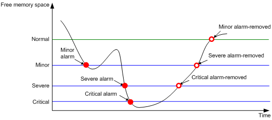
To set memory thresholds:
|
Step |
Command |
Remarks |
|
1. Enter system view. |
system-view |
N/A |
|
2. Set free-memory thresholds. |
·
In standalone mode: ·
In IRF mode: |
The defaults are as follows: · Minor alarm threshold—96 MB. · Severe alarm threshold—64 MB. · Critical alarm threshold—48 MB. · Normal state threshold—128 MB. |
|
3. Set the memory usage threshold. |
·
In standalone mode: ·
In IRF mode: |
By default, the memory usage threshold is 100%. |
Setting temperature alarm thresholds
The device monitors its temperature through temperature sensors, based on the following thresholds:
· Low-temperature threshold.
· High-temperature warning threshold.
· High-temperature alarming threshold.
· High-temperature shutdown threshold.
When the temperature drops below the low-temperature threshold or reaches the high-temperature warning threshold, the device performs the following operations:
· Logs the event.
· Sends a log message.
· Sends a trap.
When the temperature reaches the high-temperature alarming threshold, the device performs the following operations:
· Logs the event.
· Sends log messages repeatedly.
· Sets the LEDs on the device panel.
When the temperature of an LPU or switching fabric module reaches the high-temperature shutdown threshold, the device performs the following operations:
· Logs the event.
· Sends a log message.
· Shuts down the LPU.
The shutdown thresholds are not configurable. To view shutdown thresholds for cards, use the display environment command.
Different cards support different types of temperature sensors. To view supported temperature sensor types, use the display environment command.
To configure the temperature alarm thresholds:
Isolating a switching fabric module
You can isolate a switching fabric module or its channels from the forwarding plane. An isolated switching fabric module or channel does not receive any traffic.
Isolating a switching fabric module or channel does not affect operations on the control panel, such as protocol packet resolution and protocol calculation. The switching fabric module or channel can forward traffic immediately after you cancel the isolation.
|
|
IMPORTANT: Isolating the only switching fabric module of the switch disables the forwarding feature. If the switch has multiple switching fabric modules, isolating a switching fabric module decreases the forwarding bandwidth and reduces the forwarding performance. |
To isolate a switching fabric module:
|
Step |
Command |
Remarks |
|
1. Enter system view. |
system-view |
N/A |
|
2. Isolate a switching fabric module or channel. |
·
In standalone mode: ·
In IRF mode: |
By default, a switching fabric module is not isolated from the forwarding plane and forwards traffic. To minimize impact on forwarding performance, isolate only the failed channels. |
Configuring global on-demand diagnostics
Configure global on-demand diagnostics to detect problems on the initialized device.
Before you run a global on-demand diagnostic test, start the device with factory defaults and verify that no cables or transceiver modules are connected to service ports of the device.
After you run the test, you must reboot the device.
To configure global on-demand diagnostics:
|
Task |
Command |
Remarks |
|
Run a global on-demand diagnostic test. |
diagnostic start test test-name |
This command is available only when the device operates in standalone mode. |
Verifying and diagnosing transceiver modules
Verifying transceiver modules
You can use one of the following methods to verify the genuineness of a transceiver module:
· Display the key parameters of a transceiver module, including its transceiver type, connector type, central wavelength of the transmit laser, transfer distance, and vendor name.
· Display its electronic label. The electronic label is a profile of the transceiver module and contains the permanent configuration, including the serial number, manufacturing date, and vendor name. The data is written to the storage component during debugging or testing.
The electrical label information depends on the transceiver module model.
To verify transceiver modules, execute the following commands in any view:
|
Task |
Command |
Remarks |
|
Display the key parameters of transceiver modules. |
display transceiver interface [ interface-type interface-number ] |
N/A |
|
Display the electrical label information of transceiver modules. |
display transceiver manuinfo interface [ interface-type interface-number ] |
This command cannot display information for some transceiver modules. |
Diagnosing transceiver modules
The device provides the alarm and digital diagnosis features for transceiver modules. When a transceiver module fails or is not operating correctly, you can perform the following tasks:
· Check the alarms that exist on the transceiver module to identify the fault source.
· Examine the key parameters monitored by the digital diagnosis feature, including the temperature, voltage, laser bias current, TX power, and RX power.
To diagnose transceiver modules, execute the following commands in any view:
|
Task |
Command |
Remarks |
|
Display transceiver alarms. |
display transceiver alarm interface [ interface-type interface-number ] |
N/A |
|
Display the current values of the digital diagnosis parameters on transceiver modules. |
display transceiver diagnosis interface [ interface-type interface-number ] |
This command cannot display information about some transceiver modules. |
Configuring user process maintenance parameters
H3C Comware V7 is a modular network operating system based on the Linux kernel. Comware V7 software features run as independent kernel threads or user processes. A kernel thread runs in kernel space. A user process runs in user space.
Most Comware V7 software features run as user processes. Each process uses an independent space. The failure of a process does not affect other processes. The system automatically monitors user processes. If a process crashes, the system generates a core file to save the relevant information. You can use core files for troubleshooting.
To configure user process maintenance parameters, execute the following commands in user view:
|
Task |
Command |
Remarks |
|
Enable or disable the system to generate core files for crashes of a process and set the maximum number of core files. |
·
In IRF mode: |
By default, the system generates a core file for the first crash of a process and does not generate any core files for subsequent crashes of the process. |
|
Specify the directory for saving core files. |
The default directory for saving core files is flash: on an MPU. Make sure the directory for saving core files on the active MPU or global active MPU is not NULL and is accessible. If the directory is NULL or is not accessible, the system cannot save core files or the diagnostic information collected by using the display diagnostic-information command. |
Displaying and maintaining device management configuration
Before using the display diagnostic-information command to save operating statistics to a file, examine the directory for saving core files on the active MPU or global active MPU. Make sure the directory is not NULL and is accessible. To display the directory, use the display exception filepath command.
Before executing the display diagnostic-information command, perform the following tasks:
· Use the display cpu-usage command to display CPU usage statistics.
· Use the display memory command to display memory usage statistics.
Make sure the CPU usage is not 100% and the memory usage is not higher than 90% before executing the display diagnostic-information command.
The display hardware-resource and display system stable state commands are available in Release 1138P01 and later versions.
Standalone mode
Execute display commands in any view and reset commands in user view.
|
Task |
Command |
|
Display device alarm information. |
display alarm [ slot slot-number ] |
|
Display the system time, date, local time zone, and daylight saving time. |
display clock |
|
Display the copyright statement. |
display copyright |
|
Display CPU usage statistics. |
display cpu-usage [ slot slot-number [ cpu cpu-number ] ] |
|
Display CPU usage monitoring configuration. |
display cpu-usage configuration [ slot slot-number [ cpu cpu-number ] ] |
|
Display historical CPU usage statistics in a chart. |
display cpu-usage history [ job job-id ] [ slot slot-number [ cpu cpu-number ] ] |
|
Display hardware information. |
display device [ flash ] [ slot slot-number [ subslot subslot-number ] | verbose ] |
|
Display the electronic label information of the device. |
display device manuinfo [ slot slot-number ] |
|
Display the electronic label information of a fan. |
display device manuinfo fan fan-id |
|
Display the electronic label information of a power supply. |
display device manuinfo power power-id |
|
Display global on-demand diagnostic test configuration. |
display diagnostic content [ slot slot-number ] [ verbose ] |
|
Display the operating statistics for multiple feature modules. |
display diagnostic-information [ hardware | infrastructure | l2 | l3 | service ] [ filename ] |
|
Display device temperature information. |
display environment [ slot slot-number ] |
|
Display the directory for saving core files on an MPU. |
display exception filepath [ slot slot-number [ cpu cpu-number ] ] |
|
Display the operating states of fans. |
display fan [ fan-id ] |
|
Display hardware resource operating mode information. |
display hardware-resource [ tcam ] |
|
Display memory usage statistics. |
display memory [ slot slot-number [ cpu cpu-number ] ] |
|
Display memory alarm thresholds and statistics. |
display memory-threshold [ slot slot-number [ cpu cpu-number ] ] |
|
Display power supply information. |
display power [ power-id ] |
|
Display job configuration information. |
display scheduler job [ job-name ] |
|
Display job execution log information. |
display scheduler logfile |
|
Display the automatic reboot schedule. |
display scheduler reboot |
|
Display schedule information. |
display scheduler schedule [ schedule-name ] |
|
Display system stability and status information. |
display system stable state [ mdc { id | all } ] |
|
Display system operating mode information. |
display system-working-mode |
|
Display system version information. |
display version |
|
Display the startup software image upgrade history records of the MPU. |
display version-update-record |
|
Clear job execution log information. |
reset scheduler logfile |
|
Clear the startup software image upgrade history records of the MPU. |
reset version-update-record |
IRF mode
Execute display commands in any view and reset commands in user view.
|
Task |
Command |
|
Display device alarm information. |
display alarm [ chassis chassis-number slot slot-number ] |
|
Display the system time ,date, local time zone, and daylight saving time. |
display clock |
|
Display the copyright statement. |
display copyright |
|
Display CPU usage statistics. |
display cpu-usage [ chassis chassis-number slot slot-number [ cpu cpu-number ] ] |
|
Display CPU usage monitoring configuration. |
display cpu-usage configuration [ chassis chassis-number slot slot-number [ cpu cpu-number ] ] |
|
Display historical CPU usage statistics in a chart. |
display cpu-usage history [ job job-id ] [ chassis chassis-number slot slot-number [ cpu cpu-number ] ] |
|
Display hardware information. |
display device [ flash ] [ chassis chassis-number [ slot slot-number [ subslot subslot-number ] ] | verbose ] |
|
Display the electronic label information of the device. |
display device manuinfo [ chassis chassis-number [ slot slot-number ] ] |
|
Display the electronic label information of a fan. |
display device manuinfo chassis chassis-number fan fan-id |
|
Display the electronic label information of a power supply. |
display device manuinfo chassis chassis-number power power-id |
|
Display configurations of global on-demand diagnostic tests. |
display diagnostic content [ chassis chassis-number [ slot slot-number ] ] [ verbose ] |
|
Display the operating statistics for multiple feature modules. |
display diagnostic-information [ hardware | infrastructure | l2 | l3 | service ] [ filename ] |
|
Display device temperature information. |
display environment [ chassis chassis-number [ slot slot-number ] ] |
|
Display the directory for saving core files on an MPU. |
display exception filepath [ chassis chassis-number slot slot-number [ cpu cpu-number ] ] |
|
Display the operating states of fans. |
display fan [ chassis chassis-number [ fan-id ] ] |
|
Display hardware resource operating mode information. |
display hardware-resource [ tcam ] |
|
Display memory usage statistics. |
display memory [ chassis chassis-number slot slot-number [ cpu cpu-number ] ] |
|
Display memory alarm thresholds and statistics. |
display memory-threshold [ chassis chassis-number slot slot-number [ cpu cpu-number ] ] |
|
Display power supply information. |
display power [ chassis chassis-number [ power-id ] ] |
|
Display job configuration information. |
display scheduler job [ job-name ] |
|
Display job execution log information. |
display scheduler logfile |
|
Display the automatic reboot schedule. |
display scheduler reboot |
|
Display schedule information. |
display scheduler schedule [ schedule-name ] |
|
Display system stability and status information. |
display system stable state [ mdc { id | all } ] |
|
Display system operating mode information. |
display system-working-mode |
|
Display system version information. |
display version |
|
Display the startup software image upgrade history records of the global active MPU. |
display version-update-record |
|
Clear job execution log information. |
reset scheduler logfile |
|
Clear the startup software image upgrade history records of the global active MPU. |
reset version-update-record |
Configuring MDCs
MDC requires a license to run on the device. If no license is installed or the license expires, you cannot create, start, or use non-default MDCs. For more information about licenses, see "Managing licenses."
Overview
The Multitenant Device Context (MDC) technology can partition a physical device or an IRF fabric into multiple logical devices called MDCs. Each MDC uses its own hardware and software resources, runs independently of other MDCs, and provides services for its own customer. Creating, starting, rebooting, or deleting an MDC does not affect any other MDCs. From the user's perspective, an MDC is a standalone physical device.
Each MDC is isolated from the other MDCs on the same physical device and cannot directly communicate with them.
To manage the MDCs on the same physical device, you only need to log in to the physical device.
MDC applications
As shown in Figure 37, LAN 1, LAN 2, and LAN 3 are three companies' LANs. To provide access service for the three companies, you can deploy a single physical device and configure an MDC for each company on the device. Then, the administrators of each company can log in only to their own MDC to maintain their own network, without affecting any other MDC or network. The effect equals deploying a separate gateway for each company.
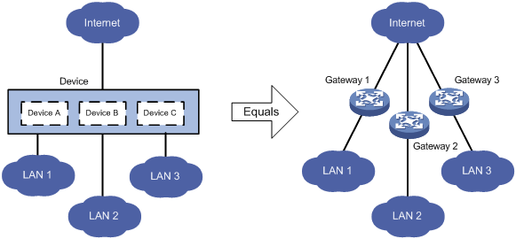
Default MDC and non-default MDCs
A device supporting MDCs is called the default MDC (for example, Device in Figure 37). The default MDC always uses the name Admin and the ID 1. You cannot delete it or change its name or ID.
When you log in to the physical device, you are logged in to the default MDC. Configuring the physical device is the same as configuring the default MDC.
On the default MDC, you can perform the following tasks:
· Manage the entire physical device.
· Create and delete non-default MDCs, for example, Device A, Device B, and Device C in Figure 37.
· Assign resources to non-default MDCs. These resources include interfaces, CPU resources, and memory space.
No MDCs can be created on a non-default MDC. Administrators of non-default MDCs can only manage and maintain their respective MDCs.
A non-default MDC can use only the resources assigned to it. It cannot use the resources assigned to other MDCs or the remaining resources on the physical device. Resources that are not assigned to any non-default MDC belong to the default MDC.
Unless otherwise stated, the term "MDC" refers to a non-default MDC and all operations are performed on the default MDC in the following sections.
Feature and software version compatibility
This feature is available in Release 1138P01 and later versions.
MDC configuration task list
|
|
IMPORTANT: To configure MDCs for a device that you want to add to an IRF fabric, add the device to the IRF fabric before configuring MDCs. After a device joins an IRF fabric, it reboots and loads the master's configuration instead of its own. |
|
Tasks at a glance |
|
(Required.) Creating an MDC |
|
Assigning hardware resources to MDCs: · (Required.) Assigning physical interfaces and LPUs to MDCs · (Optional.) Specifying a CPU weight for an MDC · (Optional.) Specifying a memory space percentage for an MDC |
|
(Required.) Starting an MDC |
|
(Required.) Accessing an MDC |
You can assign hardware resources to MDCs before or after you start the MDCs. As a best practice, assign MDCs resources before starting them.
Creating an MDC
|
Step |
Command |
Remarks |
|
1. Enter system view. |
system-view |
N/A |
|
2. Create an MDC. |
mdc mdc-name [ id mdc-id ] |
By default, there is a default MDC with the name Admin and ID 1. The default MDC is system defined. You cannot delete it. The MDC starts to work after you execute the mdc start command. The device supports a maximum of eight non-default MDCs. |
To delete an MDC, follow these steps to make sure the service modules used by the MDC can be correctly assigned to other MDCs and operate:
1. Enter the view of the MDC.
2. Execute the display this command to view the effective configuration for the MDC.
3. Use the undo mdc start command to stop the MDC.
4. Use the undo location command to reclaim the LPUs assigned to the MDC.
5. Use the undo allocate interface command to reclaim the physical interfaces assigned to the MDC.
6. Use the undo mdc command to delete the MDC.
Assigning hardware resources to MDCs
When you create an MDC, the system automatically assigns CPU and memory space resources to the MDC to ensure its operation. You can adjust the resource allocations as required.
An MDC needs interfaces to forward packets. However, the system does not automatically assign LPUs or interfaces to MDCs. You must assign interfaces and LPUs to MDCs.
Assigning physical interfaces and LPUs to MDCs
Configuration guidelines
You can assign multiple physical interfaces to a non-default MDC. A physical interface must meet the following requirements to be assigned to a non-default MDC:
· The interface is not the console port. The console port belongs to the default MDC. You cannot assign a console port to a non-default MDC.
· The interface is not the management Ethernet interface. The physical management Ethernet interface of the device belongs to the default MDC and cannot be assigned to a non-default MDC. When a non-default MDC is created, the system automatically creates virtual management Ethernet interfaces for the MDC, one virtual management Ethernet interface for each physical management Ethernet interface. Each virtual management Ethernet interface uses the same interface number, physical port, and link as the corresponding physical management Ethernet interface. You can assign IP addresses to the virtual management Ethernet interfaces for MDCs so MDC administrators can access and manage their respective MDCs. The IP addresses for virtual management Ethernet interfaces do not need to belong to the same network segment.
· The interface belongs to the default MDC. To assign a physical interface that belongs to one non-default MDC to another non-default MDC, you must remove the existing assignment by using the undo allocate interface command.
· The LPU where the interface resides is not assigned to any MDC.
When you assign physical interfaces and LPUs to MDCs, follow these guidelines:
· For an MDC to use a physical interface, you must perform the following tasks:
a. Assign the physical interface to the MDC.
b. Authorize the MDC to use the LPU where the physical interface resides.
· Interfaces on LPUs are grouped. The interfaces in a group must be assigned to or removed from the same MDC at the same time. Different groups of interfaces on an LPU can be assigned to different MDCs. Table 15 shows the interface grouping information.
Table 15 Interface grouping on LPUs
|
LPU type |
Interface grouping |
|
FC and FX cards |
Interfaces are grouped by interface number in ascending order, starting from 1. · 1G SFP, 10G SFP+, 10/100/1000Base-T, and 10GBase-T card—Each group has 24 interfaces. · 40G QSFP+ card—Each group has six interfaces. · 100G CXP and 100G CFP2 card—Each group has two interfaces. |
|
FD and FE cards |
Each card has one interface group. All interfaces on the card belong to the group. |
· A physical interface can be assigned to only one MDC.
· Assigning or reclaiming a physical interface restores the settings of the interface to the defaults. If the MDC administrator configures the interface during the assigning or reclaiming operation, settings made before the operation is completed are lost.
· To configure parameters for a physical interface that has been assigned to an MDC, you must log in to the MDC.
· To use the shutdown command to shut down the management Ethernet interface, you must be on the default MDC.
When you assign physical interfaces and LPUs to MDCs on an IRF fabric, also follow these guidelines:
· To remove an LPU that holds the IRF physical interface of a non-default MDC, first complete the following tasks:
a. Remove the IRF physical interface configuration for the LPU.
b. Use the save command to save the running configuration.
· IRF links can belong to the default MDC or non-default MDCs. As a best practice for link availability, establish a minimum of two IRF links by using different LPUs. An IRF link can belong to one or more MDCs. The two IRF physical interfaces of an IRF link can belong to the same MDC or different MDCs, as shown in Figure 38.
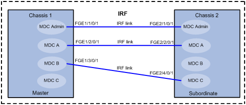
· To assign an IRF physical interface to an MDC or reclaim an IRF physical interface from an MDC, complete the following tasks:
a. Use the shutdown command to shut down the interface.
b. Use the undo port group interface command to remove the binding of the physical interface to the IRF port. For more information about the undo port group interface command, see Virtual Technologies Command Reference.
c. Assign or reclaim the IRF physical interface.
d. Use the save command to save the running configuration.
· Assigning an IRF physical interface to or reclaiming an IRF physical interface from an MDC causes the following problems:
¡ The IRF configuration on the interface is lost.
¡ The IRF link is closed.
To avoid IRF fabric split, make sure each member device always has a minimum of one IRF link in up state.
Configuration considerations
Before assigning physical interfaces and LPUs to MDCs, determine the following items:
· Number of MDCs.
· Number of physical interfaces that each MDC needs.
· Interface numbers of the physical interfaces to be assigned to MDCs.
· Location of each LPU that holds the physical interfaces to be assigned.
Configuration procedure
To assign physical interfaces to an MDC, you must reclaim the LPUs where the physical interfaces reside from all MDCs, including the default MDC.
To assign physical interfaces and LPUs to an MDC:
|
Step |
Command |
Remarks |
|
1. Enter system view. |
system-view |
N/A |
|
2. Enter the MDC view of the default MDC. |
mdc Admin |
N/A |
|
3. Identify the LPUs that the default MDC is authorized to use. |
display this |
Search the command output for undo location commands. If the undo location command is not displayed for an LPU, the default MDC has been authorized to use the LPU. |
|
4. Reclaim the LPUs. |
·
In standalone mode: ·
In IRF mode: |
To reclaim multiple LPUs from the default MDC, execute this command multiple times. |
|
5. Return to system view. |
quit |
N/A |
|
6. Enter the MDC view for the MDC to which you want to assign physical interfaces. |
mdc mdc-name [ id mdc-id ] |
N/A |
|
7. Identify the LPUs that the MDC is authorized to use. |
display this |
Search the command output for location commands. If the location command is displayed for an LPU, the MDC has been authorized to use the LPU. |
|
8. Reclaim the LPUs. |
·
In standalone mode: ·
In IRF mode: |
To reclaim multiple LPUs from the MDC, execute this command multiple times. |
|
9. Assign physical interfaces to the MDC. |
allocate interface interface-list |
By default, all physical interfaces belong to the default MDC. A non-default MDC cannot use any physical interfaces. To assign multiple physical interfaces to an MDC, execute this command multiple times. |
|
10. Authorize the MDC to use an LPU. |
·
In standalone mode: ·
In IRF mode: |
By default, all LPUs belong to the default MDC. A non-default MDC cannot use any LPUs. Authorize an MDC to use an LPU only if interfaces on the LPU have been assigned to the MDC. If you have assigned interfaces on multiple LPUs to the MDC, execute this command for each of the LPUs. |
Specifying a CPU weight for an MDC
To ensure correct operation of all MDCs, assign the MDCs CPU weights. All MDCs share and compete for the CPU resources on the MPUs in the system. All MDCs that are authorized to use the same LPU share and compete for the CPU resources on the LPU. If one MDC occupies too many of the CPU resources, the other MDCs might not be able to operate.
The amount of CPU resources an MDC can use depends on the percentage of its CPU weight among the CPU weights of all MDCs that share the same CPU. For example, if three MDCs share the same CPU, setting their weights to 10, 10, and 5 is equivalent to setting their weights to 2, 2, and 1.
· The two MDCs with the same weight can use the CPU for approximately the same period of time.
· The third MDC can use the CPU for approximately half of the time for each of the other two MDCs.
The CPU weight specified for an MDC takes effect on all MPUs and all LPUs that the MDC can use.
To specify a CPU weight for an MDC:
|
Step |
Command |
Remarks |
|
1. Enter system view. |
system-view |
N/A |
|
2. Enter MDC view. |
mdc mdc-name [ id mdc-id ] |
N/A |
|
3. Specify a CPU weight for the MDC. |
limit-resource cpu weight weight-value |
By default, each MDC has a CPU weight of 10. You can use this command to change the CPU weight for a non-default MDC. The CPU weight for the default MDC cannot be changed. |
Specifying a memory space percentage for an MDC
All MDCs share and compete for the memory space of the MPUs in the system. If an MDC occupies too much memory space, the other MDCs might not be able to operate correctly. To avoid this problem, specify a memory space percentage for each MDC.
Before you specify a memory space percentage for an MDC, use the display mdc resource command to view how much memory space the MDC is using. Make sure the memory space you assign to an MDC is sufficient for the MDC to operate correctly.
To specify a memory space percentage for an MDC:
|
Step |
Command |
Remarks |
|
1. Enter system view. |
system-view |
N/A |
|
2. Enter MDC view. |
mdc mdc-name [ id mdc-id ] |
N/A |
|
3. Specify a memory space percentage for the MDC. |
·
In standalone mode: ·
In IRF mode: |
By default, all MDCs share the memory space on the MPUs in the system, and an MDC can use all the free memory space. |
Starting an MDC
For an MDC to operate, you must start the MDC. Starting an MDC is the same as powering on a device.
After you start an MDC, the MDC first starts the automatic configuration process. To verify whether the process is completed, use the switchto mdc command to log in to the MDC. If the servers for automatic configuration are not available, stop the automatic configuration process as prompted. For more information about automatic configuration, see "Using automatic configuration."
To start an MDC:
|
Step |
Command |
|
1. Enter system view. |
system-view |
|
2. Enter MDC view. |
mdc mdc-name [ id mdc-id ] |
|
3. Start the MDC. |
mdc start |
Accessing an MDC
A non-default MDC operates in the same way as a standalone device. From the system view of the default MDC, you can log in to a non-default MDC and enter MDC system view. To allow administrators to log in to a non-default MDC by using Telnet or SSH, you must complete one of the following tasks in MDC system view:
· Assign an IP address to the management Ethernet interface.
· Create a VLAN interface on the MDC and assign an IP address to the interface.
To return from an MDC to the default MDC, use the switchback or quit command.
To log in to a non-default MDC from the system view of the default MDC:
|
Step |
Command |
Remarks |
|
1. Enter system view. |
system-view |
N/A |
|
2. Log in to an MDC. |
switchto mdc mdc-name |
You use this command to log in to only an MDC that is in active state. |
Displaying and maintaining MDCs
Execute the following display commands in any view on the default MDC:
|
Task |
Command |
|
Display MDCs and their status. |
display mdc [ name mdc-name ] |
|
Display the interfaces of MDCs. |
display mdc [ name mdc-name ] interface |
|
Display the CPU and memory space usage of MDCs in standalone mode. |
display mdc [ name mdc-name ] resource [ cpu | memory ] [ slot slot-number [ cpu cpu-number ] ] |
|
Display the CPU and memory space usage of MDCs in IRF mode. |
display mdc [ name mdc-name ] resource [ cpu | memory ] [ chassis chassis-number slot slot-number [ cpu cpu-number ] ] |
Execute the following display commands in any view on a non-default MDC:
|
Task |
Command |
|
Display the ID, name, and status of the MDC. |
display mdc |
|
Display the interfaces of the MDC. |
display mdc interface |
|
Display the CPU and memory space usage of the MDC in standalone mode. |
display mdc resource [ cpu | memory ] [ slot slot-number [ cpu cpu-number ] ] |
|
Display the CPU and memory space usage of the MDC in IRF mode. |
display mdc resource [ cpu | memory ] [ chassis chassis-number slot slot-number [ cpu cpu-number ] ] |
MDC configuration examples
MDC configuration example in standalone mode
Network requirements
As shown in Figure 39, two departments need to use the device to access the Internet.
Configure two MDCs on the device to meet the Internet access requirements of two departments. Use the default allocation settings for memory space and CPU resources.
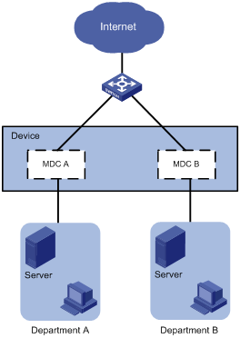
Configuration procedure
1. Create and configure MDCs:
# Create MDCA for Department A.
<Device> system-view
[Device] mdc MDCA
It will take some time to create MDC...
MDC created successfully.
[Device-mdc-2-MDCA] quit
# Create MDCB for Department B.
[Device] mdc MDCB
It will take some time to create MDC...
MDC created successfully.
[Device-mdc-3-MDCB] quit
# Reclaim the LPU in slot 2 from the default MDC.
[Device] mdc Admin
[Device-mdc-1-Admin] undo location slot 2
The configuration associated with the specified slot of MDC will be lost. Continue? [Y/N]:y
[Device-mdc-1-Admin] quit
# Assign interfaces Ten-GigabitEthernet 2/0/1 through Ten-GigabitEthernet 2/0/24 to MDCA.
[Device] mdc MDCA
[Device-mdc-2-MDCA] allocate interface ten-gigabitethernet 2/0/1 to ten-gigabitethernet 2/0/24
Configuration of the interfaces will be lost. Continue? [Y/N]:y
Execute the location slot command in this view to make the configuration take effect.
[Device-mdc-2-MDCA] quit
# Authorize MDCA to use the LPU in slot 2.
[Device-mdc-2-MDCA] location slot 2
# Set the CPU weight to 5 for MDCA.
[Device-mdc-2-MDCA] limit-resource cpu weight 5
# Start MDCA.
[Device-mdc-2-MDCA] mdc start
It will take some time to start MDC...
MDC started successfully.
[Device-mdc-2-MDCA] quit
# Assign interfaces Ten-GigabitEthernet 2/0/25 through Ten-GigabitEthernet 2/0/48 to MDCB.
[Device] mdc MDCB
[Device-mdc-3-MDCB] allocate interface ten-gigabitethernet 2/0/25 to ten-gigabitethernet 2/0/48
Configuration of the interfaces will be lost. Continue? [Y/N]:y
Execute the location slot command in this view to make the configuration take effect.
# Authorize MDCB to use the LPU in slot 2.
[Device-mdc-3-MDCB] location slot 2
# Set the CPU weight to 5 for MDCB.
[Device-mdc-3-MDCB] limit-resource cpu weight 5
# Start MDCB.
[Device-mdc-3-MDCB] mdc start
It will take some time to start MDC...
MDC started successfully.
[Device-mdc-3-MDCB] quit
2. Configure the management Ethernet interface for MDCA:
# Log in to MDCA from the default MDC. Press Ctrl+D as prompted to access the CLI of MDCA.
[Device] switchto mdc MDCA
******************************************************************************
* Copyright (c) 2004-2015 Hangzhou H3C Tech. Co., Ltd. All rights reserved. *
* Without the owner's prior written consent, *
* no decompiling or reverse-engineering shall be allowed. *
******************************************************************************
Automatic configuration is running, press CTRL_D to break or press CTRL_B to
switch back to the default MDC.
<Device> system-view
# Change the device name to MDCA for easy identification of the MDC.
[Device] sysname MDCA
# To enable the MDC administrator to remotely manage the MDC, assign an IP address to the management Ethernet interface and enable the Telnet service.
[MDCA] interface m-gigabitethernet 0/0/0
[MDCA-M-GigabitEthernet0/0/0] ip address 192.168.1.251 24
[MDCA-M-GigabitEthernet0/0/0] quit
[MDCA] telnet server enable
[MDCA] user-interface vty 0 63
[MDCA-line-vty0-63] authentication-mode none
[MDCA-line-vty0-63] user-role mdc-admin
# Return to the default MDC.
[MDCA-line-vty0-63] return
<MDCA> switchback
[Device]
3. Configure the management Ethernet interface for MDCA:
# Log in to MDCB from the default MDC. Press Ctrl+D as prompted to access the CLI of MDCB.
[Device] switchto mdc MDCB
******************************************************************************
* Copyright (c) 2004-2015 Hangzhou H3C Tech. Co., Ltd. All rights reserved. *
* Without the owner's prior written consent, *
* no decompiling or reverse-engineering shall be allowed. *
******************************************************************************
Automatic configuration is running, press CTRL_D to break or press CTRL_B to
switch back to the default MDC.
<Device> system-view
# Change the device name to MDCB for easy identification of the MDC.
[Device] sysname MDCB
# To enable the MDC administrator to remotely manage the MDC, assign an IP address to the management Ethernet interface and enable the Telnet service.
[MDCB] interface m-gigabitethernet 0/0/0
[MDCB-M-GigabitEthernet0/0/0] ip address 192.168.2.252 24
[MDCB-M-GigabitEthernet0/0/0] quit
[MDCB] telnet server enable
[MDCB] user-interface vty 0 63
[MDCB-line-vty0-63] authentication-mode none
[MDCB-line-vty0-63] user-role mdc-admin
# Return to the default MDC.
[MDCB-line-vty0-63] return
<MDCB> switchback
[Device]
Verifying the configuration
1. Verify that the MDCs exist and are operating correctly.
<Device> display mdc
ID Name Status
1 Admin active
2 MDCA active
3 MDCB active
The output shows that the MDCs have been created and are operating correctly.
2. Log in to MDCA as an administrator of Department A and then view the current configuration of the MDC.
C:\> telnet 192.168.1.251
******************************************************************************
* Copyright (c) 2004-2015 Hangzhou H3C Tech. Co., Ltd. All rights reserved. *
* Without the owner's prior written consent, *
* no decompiling or reverse-engineering shall be allowed. *
******************************************************************************
<MDCA> display current-configuration
...
MDC configuration example in IRF mode
Network requirements
As shown in Figure 40, two departments need to use the IRF fabric to access the Internet. In the IRF fabric, each member device has two LPUs. Each LPU has 48 Ten-GigabitEthernet interfaces.
The two member devices are connected with two IRF links. The IRF port on the master is IRF port 1. The IRF port on the subordinate member is IRF port 2. IRF port 1 is bound with Ten-GigabitEthernet 1/2/0/1 and Ten-GigabitEthernet 1/3/0/1. IRF port 2 is bound with Ten-GigabitEthernet 2/2/0/1 and Ten-GigabitEthernet 2/3/0/1.
Configure two MDCs on the IRF fabric to meet the Internet access requirements of two departments. Use the default allocation settings for memory space and CPU resources. Assign Ten-GigabitEthernet 1/2/0/1 through Ten-GigabitEthernet 1/2/0/24 and Ten-GigabitEthernet 2/2/0/1 through Ten-GigabitEthernet 2/2/0/24 to MDCA. Assign Ten-GigabitEthernet 1/3/0/25 through Ten-GigabitEthernet 1/3/0/48 and Ten-GigabitEthernet 2/3/0/25 through Ten-GigabitEthernet 2/3/0/48 to MDCB.
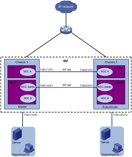
Configuration procedure
The IRF fabric has been established in this example.
1. Remove IRF port bindings:
# Shut down Ten-GigabitEthernet 1/2/0/1 and Ten-GigabitEthernet 2/2/0/1.
<IRF> system-view
[IRF] interface range ten-gigabitethernet 1/2/0/1 ten-gigabitethernet 2/2/0/1
[IRF-if-range] shutdown
[IRF-if-range] quit
# Remove the binding for IRF port 1/1.
[IRF] irf-port 1/1
[IRF-irf-port1/1] undo port group interface Ten-GigabitEthernet1/2/0/1
[IRF-irf-port1/1] quit
# Remove the binding for IRF port 2/2.
[IRF] irf-port 2/2
[IRF-irf-port2/2] undo port group interface Ten-GigabitEthernet2/2/0/1
[IRF-irf-port2/2] quit
2. Create and configure MDCA:
# Create MDCA for Department A.
[IRF] mdc MDCA
It will take some time to create MDC...
MDC created successfully.
[IRF-mdc-2-MDCA] quit
# Reclaim the LPU in slot 2 of each member device from the default MDC.
[IRF] mdc Admin
[IRF-mdc-1-Admin] undo location chassis 1 slot 2
The configuration associated with the specified slot of MDC will be lost. Continue? [Y/N]:y
[IRF-mdc-1-Admin] undo location chassis 2 slot 2
The configuration associated with the specified slot of MDC will be lost. Continue? [Y/N]:y
[IRF-mdc-1-Admin] quit
# Assign Ten-GigabitEthernet 1/2/0/1 through Ten-GigabitEthernet 1/2/0/24 and Ten-GigabitEthernet 2/2/0/1 through Ten-GigabitEthernet 2/2/0/24 to MDCA.
[IRF] mdc MDCA
[IRF-mdc-2-MDCA] allocate interface ten-gigabitethernet 1/2/0/1 to ten-gigabitethernet 1/2/0/24
Configuration of the interfaces will be lost. Continue? [Y/N]:y
Execute the location slot command in this view to make the configuration take effect.
[IRF-mdc-2-MDCA] allocate interface ten-gigabitethernet 2/2/0/1 to ten-gigabitethernet 2/2/0/24
Configuration of the interfaces will be lost. Continue? [Y/N]:y
Execute the location slot command in this view to make the configuration take effect.
[IRF-mdc-2-MDCA] quit
# Authorize MDCA to use the two LPUs.
[IRF-mdc-2-MDCA] location chassis 1 slot 2
[IRF-mdc-2-MDCA] location chassis 2 slot 2
# Set the CPU weight to 5 for MDCA.
[IRF-mdc-2-MDCA] limit-resource cpu weight 5
# Start MDCA.
[IRF-mdc-2-MDCA] mdc start
It will take some time to start MDC...
MDC started successfully.
[IRF-mdc-2-MDCA] quit
3. Configure Ten-GigabitEthernet 1/2/0/1 and Ten-GigabitEthernet 2/2/0/1 as the IRF physical interface on MDCA:
# Log in to MDCA from the default MDC. Press Ctrl+D as prompted to stop automatic MDC configuration and access the CLI of MDCA.
[IRF] switchto mdc MDCA
******************************************************************************
* Copyright (c) 2004-2015 Hangzhou H3C Tech. Co., Ltd. All rights reserved. *
* Without the owner's prior written consent, *
* no decompiling or reverse-engineering shall be allowed. *
******************************************************************************
Automatic configuration is running, press CTRL_D to break or press CTRL_B to
switch back to the default MDC.
<IRF> system-view
# Change the device name to MDCA for easy identification of the MDC.
[IRF] sysname MDCA
# Shut down Ten-GigabitEthernet 1/2/0/1 and Ten-GigabitEthernet 2/2/0/1.
[MDCA] interface range ten-gigabitethernet 1/2/0/1 ten-gigabitethernet 2/2/0/1
[MDCA-if-range] shutdown
[MDCA-if-range] quit
[MDCA] quit
# Return to the default MDC.
<MDCA> switchback
[IRF]
# View the ID of MDCA.
[IRF] display mdc
ID Name Status
1 Admin active
2 MDCA active
# Bind Ten-GigabitEthernet 1/2/0/1 to IRF port 1/1. This setting takes effect immediately because the IRF fabric has been established. If the IRF fabric has not been established, you must activate this setting.
[IRF] irf-port 1/1
[IRF-irf-port1/1] port group mdc 2 interface ten-gigabitethernet 1/2/0/1
You must perform the following tasks for a successful IRF setup:
Save the configuration after completing IRF configuration.
Execute the "irf-port-configuration active" command to activate the IRF ports.
[IRF-irf-port1/1] quit
# Bind Ten-GigabitEthernet 2/2/0/1 to IRF port 2/2. This setting takes effect immediately because the IRF fabric has been established.
[IRF] irf-port 2/2
[IRF-irf-port2/2] port group mdc 2 interface ten-gigabitethernet 2/2/0/1
You must perform the following tasks for a successful IRF setup:
Save the configuration after completing IRF configuration.
Execute the "irf-port-configuration active" command to activate the IRF ports.
[IRF-irf-port2/2] quit
# Log in to MDCA from the default MDC.
[IRF] switchto mdc MDCA
******************************************************************************
* Copyright (c) 2004-2015 Hangzhou H3C Tech. Co., Ltd. All rights reserved. *
* Without the owner's prior written consent, *
* no decompiling or reverse-engineering shall be allowed. *
******************************************************************************
<MDCA> system-view
# Bring up Ten-GigabitEthernet 1/2/0/1 and Ten-GigabitEthernet 2/2/0/1.
[MDCA] interface range ten-gigabitethernet 1/2/0/1 ten-gigabitethernet 2/2/0/1
[MDCA-if-range] undo shutdown
[MDCA-if-range] quit
# To enable the administrator of MDCA to remotely manage MDCA, assign an IP address to the management Ethernet interface and enable the Telnet service.
[MDCA] display interface M-GigabitEthernet brief
Brief information on interfaces in route mode:
Link: ADM - administratively down; Stby - standby
Protocol: (s) - spoofing
Interface Link Protocol Primary IP Description
M-GE1/0/0/0 DOWN DOWN --
M-GE1/0/0/1 DOWN DOWN --
M-GE1/0/0/2 UP UP --
M-GE1/0/0/3 DOWN DOWN --
[MDCA] interface m-gigabitethernet 1/0/0/2
[MDCA-M-GigabitEthernet1/0/0/2] ip address 192.168.1.251 24
[MDCA-M-GigabitEthernet1/0/0/2] quit
[MDCA] telnet server enable
[MDCA] user-interface vty 0 63
[MDCA-line-vty0-63] authentication-mode none
[MDCA-line-vty0-63] user-role mdc-admin
[MDCA-line-vty0-63] return
# Return to the default MDC.
<MDCA> switchback
[IRF]
# Display IRF link information. The two IRF links are both in up state.
<IRF> display irf link
Member 1
IRF Port Interface Status
1 Ten-GigabitEthernet1/2/0/1(MDC2) UP
Ten-GigabitEthernet1/3/0/1 UP
2 disable --
Member 2
IRF Port Interface Status
1 disable --
2 Ten-GigabitEthernet2/2/0/1(MDC2) UP
Ten-GigabitEthernet2/3/0/1 UP
|
|
NOTE: To assign an IRF physical interface to a non-default MDC or establish a new IRF link on a non-default MDC, follow the configuration procedure for MDCA. In the following steps, only interfaces that are not IRF physical interfaces are assigned to MDCB. This configuration method is simpler than assigning IRF physical interfaces, because it does not require you to change the IRF port configuration. |
4. Create and configure MDCB:
# Create MDCB for Department B.
[IRF] mdc MDCB
It will take some time to create MDC...
MDC created successfully.
[IRF-mdc-3-MDCB] quit
# Reclaim the LPU in slot 3 of each member device from the default MDC.
[IRF] mdc Admin
[IRF-mdc-1-Admin] undo location chassis 1 slot 3
The configuration associated with the specified slot of MDC will be lost. Continue? [Y/N]:y
[IRF-mdc-1-Admin] undo location chassis 2 slot 3
The configuration associated with the specified slot of MDC will be lost. Continue? [Y/N]:y
[IRF-mdc-1-Admin] quit
# Assign Ten-GigabitEthernet 1/3/0/25 through Ten-GigabitEthernet1/3/0/48 and Ten-GigabitEthernet 2/3/0/25 through Ten-GigabitEthernet 2/3/0/48 to MDCB.
[IRF] mdc MDCB
[IRF-mdc-3-MDCB] allocate interface ten-gigabitethernet 1/3/0/25 to ten-gigabitethernet 1/3/0/48
Configuration of the interfaces will be lost. Continue? [Y/N]:y
Execute the location slot command in this view to make the configuration take effect.
[IRF-mdc-3-MDCB] allocate interface ten-gigabitethernet 2/3/0/25 to ten-gigabitethernet 2/3/0/48
Configuration of the interfaces will be lost. Continue? [Y/N]:y
Execute the location slot command in this view to make the configuration take effect.
# Authorize MDCB to use the two LPUs.
[IRF-mdc-3-MDCB] location chassis 1 slot 3
[IRF-mdc-3-MDCB] location chassis 2 slot 3
# Set the CPU weight to 5 for MDCB.
[IRF-mdc-3-MDCB] limit-resource cpu weight 5
# Start MDCB.
[IRF-mdc-3-MDCB] mdc start
It will take some time to start MDC...
MDC started successfully.
[IRF-mdc-3-MDCB] quit
# Restore the authorization of the two LPUs for the default MDC.
[IRF] mdc Admin
[IRF-mdc-2-Admin] location chassis 1 slot 3
[IRF-mdc-2-Admin] location chassis 2 slot 3
[IRF-mdc-2-Admin] quit
# Log in to MDCB from the default MDC. Press Ctrl+D as prompted to stop automatic MDC configuration and access the CLI of MDCB.
[IRF] switchto mdc MDCB
******************************************************************************
* Copyright (c) 2004-2015 Hangzhou H3C Tech. Co., Ltd. All rights reserved. *
* Without the owner's prior written consent, *
* no decompiling or reverse-engineering shall be allowed. *
******************************************************************************
Automatic configuration is running, press CTRL_D to break or press CTRL_B to
switch back to the default MDC.
<IRF> system-view
# Change the device name to MDCB for easy identification of the MDC.
[IRF] sysname MDCB
# To enable the administrator of MDCB to remotely manage MDCB, assign an IP address to the management Ethernet interface and enable the Telnet service.
[MDCB] display interface M-GigabitEthernet brief
Brief information on interfaces in route mode:
Link: ADM - administratively down; Stby - standby
Protocol: (s) - spoofing
Interface Link Protocol Primary IP Description
M-GE1/0/0/0 DOWN DOWN --
M-GE1/0/0/1 DOWN DOWN --
M-GE1/0/0/2 UP UP --
M-GE1/0/0/3 DOWN DOWN --
[MDCB] interface m-gigabitethernet 1/0/0/2
[MDCB-M-GigabitEthernet1/0/0/2] ip address 192.168.2.252 24
[MDCB-M-GigabitEthernet1/0/0/2] quit
[MDCB] telnet server enable
[MDCB] user-interface vty 0 63
[MDCB-line-vty0-63] authentication-mode none
[MDCB-line-vty0-63] user-role mdc-admin
# Return to the default MDC.
[MDCB-line-vty0-63] return
<MDCB> switchback
[IRF]
Verifying the configuration
1. Verify that the MDCs exist and are operating correctly.
<IRF> display mdc
ID Name Status
1 Admin active
2 MDCA active
3 MDCB active
The output shows that the MDCs have been created and are operating correctly.
2. Log in to MDCA as an administrator of Department A. View the running configuration of the MDC.
C:\> telnet 192.168.1.251
******************************************************************************
* Copyright (c) 2004-2015 Hangzhou H3C Tech. Co., Ltd. All rights reserved. *
* Without the owner's prior written consent, *
* no decompiling or reverse-engineering shall be allowed. *
******************************************************************************
<MDCA> display current-configuration
...
Using Python
Python is an easy to learn, powerful programming language. It has efficient high-level data structures and a simple but effective approach to object-oriented programming. Python's elegant syntax and dynamic typing, together with its interpreted nature, make it an ideal language for scripting and rapid application development in many areas on most platforms.
Comware V7 provides a built-in Python interpreter that supports the following items:
· Python 2.7 commands.
· Python 2.7 standard API.
· Comware V7 extended API. For more information about the Comware V7 extended API, see "Comware V7 extended Python API."
· Python scripts. You can use a Python script to configure the system.
Entering the Python shell
To use Python commands and APIs, you must enter the Python shell.
To enter the Python shell:
|
Command |
|
|
Enter the Python shell from user view. |
Executing a Python script
Execute a Python script in user view.
|
Command |
|
|
Execute a Python script. |
Exiting the Python shell
Execute this command in the Python shell.
|
Task |
Command |
|
Return to user view from the Python shell. |
exit() |
Python usage example
Network requirements
Use a Python script to download configuration files main.cfg and backup.cfg to the device. Configure the files as the main and backup configuration files for the next startup.
Figure 41 Network diagram
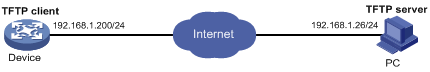
Configuration procedure
# Use a text editor on the PC to edit Python script test.py as follows:
comware.Transfer('tftp', '192.168.1.26', 'main.cfg', 'flash:/main.cfg')
comware.Transfer('tftp', '192.168.1.26', 'backup.cfg', 'flash:/backup.cfg')
comware.CLI('startup saved-configuration flash:/main.cfg main ;startup saved-configuration flash:/backup.cfg backup')
# Use TFTP to download the script to the device.
<Sysname> tftp 192.168.1.26 get test.py
<Sysname> python flash:/test.py
<Sysname>startup saved-configuration flash:/main.cfg main
Please wait...... Done.
<Sysname>startup saved-configuration flash:/backup.cfg backup
Please wait...... Done.
Verifying the configuration
# Display startup configuration files.
Current startup saved-configuration file: flash:/startup.cfg
Next main startup saved-configuration file: flash:/main.cfg
Next backup startup saved-configuration file: flash:/backup.cfg
Comware V7 extended Python API
The Comware V7 extended Python API is compatible with the Python syntax.
Importing and using the Comware V7 extended Python API
To use the Comware V7 extended Python API, you must import the API to Python.
Use either of the following methods to import and use the Comware V7 extended Python API:
· Use import comware to import the entire API and use comware.API to execute an API.
For example, to use the extended API Transfer to download file test.cfg from TFTP server 192.168.1.26:
<Sysname> python
Python 2.7.3 (default, Sep 24 2014, 14:37:26)
[GCC 4.4.1] on linux2
Type "help", "copyright", "credits" or "license" for more information.
>>> import comware
>>> comware.Transfer('tftp', '192.168.1.26', 'test.cfg', 'flash:/test.cfg', user='', password='')
<comware.Transfer object at 0x55557bc120>
· Use from comware import API to import an API and use API to execute the API.
For example, to use the extended API Transfer to download file test.cfg from TFTP server 192.168.1.26:
Python 2.7.3 (default, Sep 24 2014, 14:37:26)
[GCC 4.4.1] on linux2
Type "help", "copyright", "credits" or "license" for more information.
>>> from comware import Transfer
>>> Transfer('tftp', '192.168.1.26', 'test.cfg', 'flash:/test.cfg', user='', password='')
<comware.Transfer object at 0x55557bc0f0>
Comware V7 extended Python API functions
CLI class
CLI
Use CLI to execute Comware V7 CLI commands and create CLI objects.
Syntax
CLI(command=‘’, do_print=True)
Parameters
command: Specifies the commands to be executed. To enter multiple commands, use a space and a semicolon (;) as the delimiter. To enter a command in a view other than user view, you must first enter the commands used to enter the view. For example, you must enter ’system-view ;local-user test class manage’ to execute the local-user test class manage command.
do_print: Specifies whether to output the execution result:
· True—Outputs the execution result. This value is the default.
· False—Does not output the execution result.
Returns
CLI objects
Examples
# Add a local user with the username test.
<Sysname> python
Python 2.7.3 (default, Sep 24 2014, 14:37:26)
[GCC 4.4.1] on linux2
Type "help", "copyright", "credits" or "license" for more information.
>>> import comware
>>> comware.CLI('system-view ;local-user test class manage')
<Sysname> system-view
System View: return to User View with Ctrl+Z.
[Sysname] local-user test class manage
New local user added.
<comware.CLI object at 0x55557bc0f0>
get_output
Use get_output to get the output from executed commands.
Syntax
Returns
Output from executed commands
Examples
# Add a local user and get the output from the command.
<Sysname> python
Python 2.7.3 (default, Sep 24 2014, 14:37:26)
[GCC 4.4.1] on linux2
Type "help", "copyright", "credits" or "license" for more information.
>>> import comware
>>> c = comware.CLI('system-view ;local-user test class manage', False)
>>> c.get_output()
Sample output
['<Sysname>system-view', 'System View: return to User View with Ctrl+Z.', '[Sysname]local-user test class manage']
Transfer class
Transfer
Use Transfer to download a file from a server.
Syntax
Transfer(protocol=‘’, host=‘’, source=‘’, dest=‘’, vrf=‘’, login_timeout=10, user=‘’, password=‘’)
Parameters
protocol: Specifies the protocol used to download a file:
· ftp—Uses FTP.
· tftp—Uses TFTP.
· http—Uses HTTP.
host: Specifies the IP address of the remote server.
source: Specifies the name of the file to be downloaded from the remote server.
dest: Specifies a name for the downloaded file.
login_timeout: Specifies the timeout for the operation, in seconds. The default is 10.
user: Specifies the username for logging in to the server.
password: Specifies the login password.
Returns
Transfer object
Examples
# Download file test.cfg from TFTP server 192.168.1.26.
<Sysname> python
Python 2.7.3 (default, Sep 24 2014, 14:37:26)
[GCC 4.4.1] on linux2
Type "help", "copyright", "credits" or "license" for more information.
>>> import comware
>>> comware.Transfer('tftp', '192.168.1.26', 'test.cfg', 'flash:/test.cfg', user='', password='')
Sample output
<comware.Transfer object at 0x55557bc120>
get_error
Use get_error to get the error information from the download operation.
Syntax
Returns
If there is not error information, None is returned.
Examples
# Download file test.cfg from TFTP server 1.1.1.1 and get the error information from the operation.
<Sysname> python
Python 2.7.3 (default, Sep 24 2014, 14:37:26)
[GCC 4.4.1] on linux2
Type "help", "copyright", "credits" or "license" for more information.
>>> import comware
>>> c = comware.Transfer('tftp', '1.1.1.1', 'test.cfg', 'flash:/test.cfg', user='', password='')
>>> c.get_error()
Sample output
API get_self_slot
get_self_slot
Use get_self_slot to get the slot number of the active MPU in standalone mode, or the slot number of the global active MPU in IRF mode.
Syntax
Returns
In IRF mode, a list object in the format [chassis-number,slot-number] is returned. The chassis-number indicates the member ID of the master. The slot-number indicates the slot number of the global active MPU.
Examples
# In standalone mode, get the slot number of the active MPU.
<Sysname> python
Python 2.7.3 (default, Sep 24 2014, 14:37:26)
[GCC 4.4.1] on linux2
Type "help", "copyright", "credits" or "license" for more information.
>>> import comware
>>> comware.get_self_slot()
[-1,17]
API get_standby_slot
get_standby_slot
Use get_standby_slot to get the slot number of the standby MPU in standalone mode.
Use get_standby_slot to get the slot numbers of all global standby MPUs in IRF mode.
Syntax
Returns
In standalone mode, this command returns a list object in the format [[–1,slot-number]]. The slot-number indicates the slot number of the standby MPU. If the switch does not have a standby MPU, [ ] is returned.
In IRF mode, a list object in one of the following formats is returned:
· [ ]—The IRF fabric does not have a global standby MPU.
· [[chassis-number,slot-number]]—The IRF fabric has only one global standby MPU. The chassis-number indicates the member ID of the subordinate switch. The slot-number indicates the slot number of the global standby MPU.
· [[chassis-number1,slot-number1],[chassis-number2,slot-number2],...]—The IRF fabric has multiple global standby MPUs.
Examples
# In standalone mode, get the slot number of the standby MPU.
<Sysname> python
Python 2.7.3 (default, Sep 24 2014, 14:37:26)
[GCC 4.4.1] on linux2
Type "help", "copyright", "credits" or "license" for more information.
>>> import comware
>>> comware.get_standby_slot()
Sample output
API get_slot_range
get_slot_range
Use get_slot_range to obtain the supported slot number range.
Syntax
get_slot_range()
Returns
A dictionary object in the format {'MaxSlot': slot-number, 'MinSlot': slot-number}. The slot-number indicates the slot number of the card.
Examples
# Obtain the supported slot number range.
<Sysname> python
Python 2.7.3 (default, Sep 24 2014, 14:37:26)
[GCC 4.4.1] on linux2
Type "help", "copyright", "credits" or "license" for more information.
>>> import comware
>>> comware. get_slot_range()
Sample output
API get_slot_info
get_slot_info
Use get_slot_info to obtain information about a slot.
Syntax
get_slot_info(slot-number)
Returns
A dictionary object in the format {'Slot': slot-number, 'Status': 'Normal/Absent/Fail', 'Chassis': chassis-number, 'Role': 'Master/Standby/IO', 'Cpu': cpu-number}. The chassis-number indicates the member ID of the device. The slot-number indicates the slot number of the card. The cpu-number indicates the number of the CPU.
Examples
# Obtain information about slot 17.
<Sysname> python
Python 2.7.3 (default, Sep 24 2014, 14:37:26)
[GCC 4.4.1] on linux2
Type "help", "copyright", "credits" or "license" for more information.
>>> import comware
>>> comware.get_slot_info(17)
Sample output
{'Slot': 17, 'Status': 'Normal', 'Chassis': 0, 'Role': 'Master', 'Cpu': 0}
Managing licenses
License-based features, such as EVI, MDC, SPBM, TRILL, and FCoE, require a license to run on your device. To use a license-based feature, you must purchase a license or obtain a free trial license.
This chapter describes how to license a feature, transfer a license between devices, remove a license, and manage the license storage space.
License types
The following types of licenses are available depending on validity period:
· Permanent—A permanent license is always valid and never expires.
· Days restricted—A license valid for a limited period in days, for example, 30 days. Trial licenses are typically days restricted.
The following types of licenses are available depending on locking method:
· Device locked—A license can be installed only on the DID-specific device. The license takes effect on any MPU in the device even after an MPU replacement. The device supports this locking method.
· MPU locked—A license can be installed only on the DID-specific MPU. The license takes effect on the MPU even after the MPU is moved to a different device.
Restrictions and guidelines
When you manage licenses, follow these restrictions and guidelines:
· Use the display license feature command to identify license-based features and their licensing information.
· License registration requires a license key, hardware SN, and DID. This information is device specific. If the registration is successful, the licensing system returns an activation file. This activation file is locked to the device with the specific DID, and it cannot be used on any other devices.
· Manage licenses on the default MDC, and the licensed features will be licensed to the non-default MDCs automatically. Non-default MDCs do not support the license management. For information about MDCs, see "Configuring MDCs."
· For the license management feature to operate correctly, do not create any files named license in the flash:/ directory or modify the attributes of the license file folder in this directory.
· Do not delete or move files in the flash:/license directory on an MPU. The license management feature uses this directory for license management. An incorrect file operation can cause problems. For example, if you delete an activation file that is usable or in use, the related feature will not function correctly. If a file is missing or corrupted, copy the activation file to the directory to recover the license. To verify the license state, use the display license command.
· A registered license takes effect on the entire device in standalone mode. The device will copy the activation file to other MPUs on the device during installation.
· For a license-based feature to run correctly in an IRF fabric:
¡ Install one license for the feature on each member in the fabric.
¡ Make sure the licenses installed on the members are the same.
Registering and activating a license
You can install a maximum of five activation files on each device.
Do not open or edit the activation file, for the operation might corrupt the file. Use the Binary mode to transfer the activation file to the device from the PC.
For a successful license activation file installation, verify that the following requirements are met:
· The SN and DID used for registration match the current SN and DID of the specified device.
· No one else is installing an activation file on the device you are working with.
· Use the display power command to verify that the power monitor module and the power supplies are operating correctly.
To register and activate a license:
|
Step |
Command |
|
1. Identify the number of available license storage entries. |
display license feature |
|
2. (Optional.) Compress the license storage if the free license storage is not sufficient for licenses to be activated. |
|
|
3. Obtain the SN and DID of the device. |
display license device-id |
|
4. Identify the license key on your license. |
N/A |
|
5. Use the license key, SN, and DID to register the license at http://www.h3c.com/portal/Technical_Support___Documents/Product_Licensing/. |
N/A |
|
6. Download the activation file to the flash memory or the CF card on the MPU of the device. |
N/A |
|
7. Enter system view. |
system-view |
|
8. Install the activation file. |
·
In standalone mode: ·
In IRF mode: |
|
|
NOTE: If you can neither obtain nor re-register the activation file due to problems such as operating system and browser errors, contact H3C Support. |
Transferring a license
You can transfer a formal license from one device to another if its activation file has not expired. If the activation file has expired, the license is not transferrable. Trial licenses are not transferrable.
Transferring a license typically includes the following tasks:
1. Uninstall its activation file on the source device.
2. Register the license with H3C for the target device.
3. Activate the license on the target device.
When an activation file is uninstalled, the system creates an Uninstall file. You must provide this file when you register the license for the target device.
For a successful uninstallation, make sure no one else is uninstalling an activation file on the device you are working with.
To transfer a license:
|
Step |
Command |
|
1. Enter system view on the source device. |
system-view |
|
2. Uninstall the activation file. |
·
In standalone mode: ·
In IRF mode: |
|
3. Access the target device and display SN and DID information. |
display license device-id |
|
4. Use the Uninstall file and target device's SN and DID to register the license at http://www.h3c.com/portal/Technical_Support___Documents/Product_Licensing/. |
N/A |
|
5. Download the new activation file to the flash memory or the CF card on an MPU of the target device. |
N/A |
|
6. Install the activation file on the target device. |
|
|
NOTE: The uninstall action does not delete license data from the license storage area. To free storage space, you must compress the license storage (see "Compressing the license storage"). |
Compressing the license storage
|
|
CAUTION: The DID changes each time the license storage is compressed. Before performing a compression, make sure all activation files generated based on the old DID have been installed. They cannot be installed after the compression. |
If the license storage area is not sufficient for installing new licenses, compress the license storage. This action deletes expired licenses, uninstalled licenses, and Uninstall files. Back up the Uninstall files before you compress the license storage.
For a successful compression, make sure no one else is compressing the license storage on the device you are working with.
To compress the license storage:
|
Step |
Command |
|
1. Enter system view. |
system-view |
|
2. Compress the license storage. |
·
In standalone mode: ·
In IRF mode: |
Recovering licenses after replacement of both MPUs on the device
If you replace both MPUs on the device because they have failed at the same time, you must recover the activation files to the new MPU's flash:/license directory.
To recover an activation file:
1. Use the SN of the device to download the activation file from the H3C license center at http://www.h3c.com/portal/Technical_Support___Documents/Product_Licensing/.
2. Use the display license command to verify that the downloaded file has the same name as the original activation file name on the device.
3. If the file names are different, change the name of the downloaded file to be the same as the original activation file name on the device. If the file names are the same, skip this step.
4. Copy the downloaded activation file to the flash:/license directory on each new MPU.
5. Restart the device.
Displaying and maintaining licenses
Execute display commands in any view.
|
Task |
Command |
|
Display the SN and DID of the device (in standalone mode). |
display license device-id |
|
Display the SN and DID of an IRF member device (in IRF mode). |
display license device-id chassis chassis-number |
|
Display detailed license information (in standalone mode). |
display license [ activation-file ] |
|
Display detailed license information (in IRF mode). |
display license [ activation-file ] [ chassis chassis-number ] |
|
Display brief feature license information. |
display license feature |
Using automatic configuration
With the automatic configuration feature, the device can automatically obtain a set of configuration settings from some servers when it starts up without a configuration file. This feature simplifies network configuration, facilitates centralized management, and reduces maintenance workload.
Understanding automatic configuration
The automatic configuration feature requires the cooperation of the following servers: a DHCP server, an HTTP server, a TFTP server, and a DNS server, as shown in Figure 42.
Figure 42 Typical automatic configuration network diagram
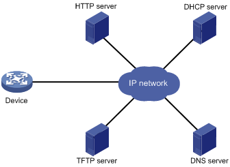
When the device is powered on without a configuration file, it automatically starts the automatic configuration process to try to obtain a set of configuration settings. If one attempt fails, the device waits 30 seconds, and then automatically starts the process again for another try. The device continues to make attempts until it obtains a set of configuration settings. To stop the process, power off the device or press Ctrl+D.
Overall automatic configuration process
As shown in Figure 43, the automatic configuration process includes the following steps:
1. The device selects an interface for automatic configuration. For more information, see "Interface selection process."
2. After finding an interface, the device enables the DHCP client on the interface and tries to obtain a set of parameters for automatic configuration, which might include a temporary IP address, a configuration file name, a TFTP server domain name, a TFTP server IP address, and a DNS server IP address. For more information, see "Automatic-configuration parameter acquisition process."
3. After obtaining automatic configuration parameters, the device tries to download a configuration file from a TFTP server or an HTTP server. For more information, see "Configuration file acquisition process."
4. If the device obtains a configuration file, it deletes its temporary settings to restore the factory defaults and executes the configuration file. If the device does not obtain a configuration file or fails to execute the configuration file, it deletes its temporary settings and stays quiet for 30 seconds. Then, the device tries again for automatic configuration by selecting another qualified interface and repeating Step 2 to Step 4. To stop the automatic configuration process, press Ctrl+D at the CLI of the device.
|
|
IMPORTANT: · To ensure quick and successful automatic configuration of a device, connect only the interface used for automatic configuration to the network. · Make sure the configuration file does not contain commands for configuring the interface used for automatic configuration. Settings configured by the commands do not take effect. · Make sure the settings in the configuration file do not conflict with the running configuration for the interface used for automatic configuration. If conflicts exist, the device does not execute the relevant commands in the configuration file. For example, the configuration file cannot contain a command that assigns an interface an IP address that is on the same subnet as the interface used for automatic configuration. The device does not execute the command. · The device does not execute the port breakout configuration commands (if any) in the obtained configuration file. To make the port breakout configuration commands take effect, you must specify the configuration file as the next-startup configuration file and reboot the device. · The device does not save the obtained configuration file. To use the configuration after a reboot, save the running configuration by using the save command. Otherwise, the device has to perform automatic configuration again after a reboot. For more information about the save command, see Fundamentals Command Reference. |
Figure 43 Automatic configuration workflow
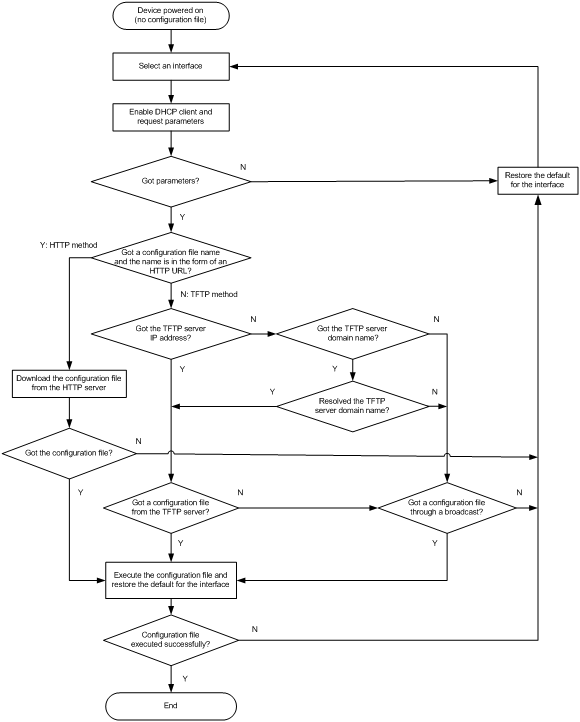
Interface selection process
The device follows the following process to select an interface for automatic configuration:
1. If the device has a management Ethernet interface that is up at Layer 2, the device uses the management Ethernet interface for automatic configuration.
2. If the device has no management Ethernet interface in up state at Layer 2 but has Layer 2 Ethernet interfaces in up state, the device selects the VLAN interface of the default VLAN.
3. If no Layer 2 Ethernet interface is in up state, the device sorts all Layer 3 Ethernet interfaces in up state first by the dictionary order of the interface types and then in ascending order of interface numbers, and selects the one with the smallest interface number among the interfaces of the first interface type.
Figure 44 Interface selection process
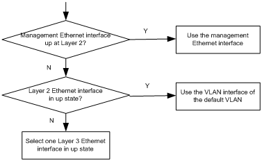
Automatic-configuration parameter acquisition process
After the device finds an interface for automatic configuration, it enables the DHCP client on the interface. Then, the DHCP client broadcasts a DHCP request to locate a DHCP server and request configuration settings. The DHCP request uses DHCP Option 55 to indicate the configuration settings the device requires, including the configuration file name, the TFTP server domain name, the TFTP server IP address, and the DNS server IP address.
After receiving a DHCP reply, the device resolves the packet for the assigned IP address. If the reply provides an IP address, the device continues to examine the following options or fields in the DHCP reply:
· Option 67 or the file field—Carries the configuration file name. The device resolves Option 67 first. If Option 67 does not contain the configuration file name, the device resolves the file field. The configuration file name might indicate a file on an HTTP server or a TFTP server.
· Option 150—Carries the TFTP server IP address. If this option contains a valid TFTP server IP address, the device starts the configuration file acquisition process. Otherwise, the device resolves Option 66.
· Option 66—Carries the TFTP server domain name. If Option 150 does not contain a TFTP server IP address, the device resolves this option for a TFTP server domain name and tries to communicate with the DNS server indicated by Option 6 to obtain the TFTP server IP address.
· Option 6—Carries the DNS server IP address.
For more information about DHCP, see Layer 3—IP Services Configuration Guide.
Configuration file acquisition process
The device requests a configuration file from an HTTP server or a TFTP server:
· If the device got a configuration file name during the automatic-configuration parameter acquisition process, the device examines the form of the configuration file name. If the configuration file name is in the form of a valid HTTP URL, the device tries to download the configuration file from the URL. See Figure 43.
· If the device did not obtain a configuration file name during the automatic-configuration parameter acquisition process, or if the device got a configuration file name that is not in the form of a valid HTTP URL, the device starts to acquire a configuration file from a TFTP server:
¡ If the device has got a TFTP server IP address, it unicasts a request to the TFTP server.
¡ If it has not, the device broadcasts a request. In this case, the device resolves only the first reply.
As shown in Figure 45, the device determines what to request from the TFTP server based on whether or not it got a configuration file name during the automatic-configuration parameter acquisition process:
¡ If the device got a configuration file name, it requests the specified configuration file.
¡ If not, it requests a configuration file named in the host name.cfg format from the TFTP server, where host name represents the host name of the device. To do so, the device first requests the host name file network.cfg, which contains mappings between IP addresses and host names. If the device fails to obtain the host name file or the file contains no entry for the device's temporary IP address, it tries to communicate with a DNS server to resolve the temporary IP address to a host name. After the device obtains the host name, it tries to obtain the configuration file for the host name.
If the device fails to obtain a configuration file specific for itself, it requests the default configuration file device.cfg from the TFTP server.
Figure 45 Configuration file acquisition process
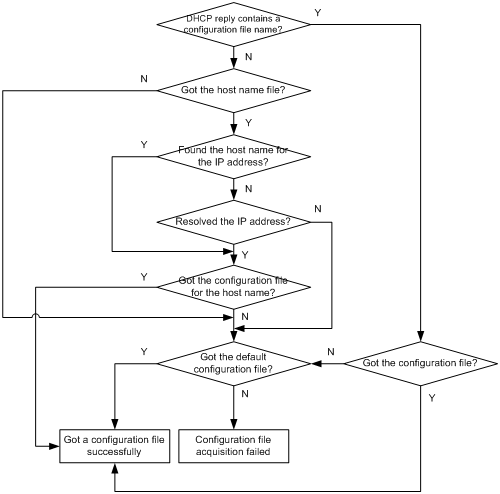
Deploying and configuring servers for automatic configuration
To implement automatic configuration, you do not need to perform any configuration on the device. However, you must deploy DHCP, TFTP, and DNS servers and configure the servers to cooperate with the device as follows:
· DHCP server—Assigns the device a set of parameters for automatic configuration, which might include a temporary IP address, a configuration file name, a TFTP server domain name, a TFTP server IP address, and a DNS server IP address. For more information about the DHCP server, see Layer 3—IP Services Configuration Guide.
· HTTP server—Assigns files for automatic configuration to the device, for example, the configuration file.
· TFTP server—Stores files required for device automatic configuration, including the configuration files and host name files. For more information about the TFTP server, see "Configuring TFTP."
· DNS server—Resolves the device's temporary IP address to its host name so the device can request a configuration file named in the host name.cfg format from the TFTP server. The DNS server might also need to resolve the TFTP server domain name to the TFTP server IP address. For more information about the DNS server, see Layer 3—IP Services Configuration Guide.
If the DHCP server, the HTTP server, the TFTP server, the DNS server, and the device are not in the same network segment, configure the DHCP relay agent on the gateway, and configure routing protocols to make sure the servers have routes to the device and vice versa.
A configuration file for automatic configuration can be in the form of a Python script. A Python script can be used to implement automatic version update or configuration assignment. For more information about Python scripts, see "Using Python."
For successful automatic configuration, make sure a Python script for automatic configuration does not contain the fips mode enable command.
DHCP server configuration guidelines
When configuring the DHCP server, follow these guidelines:
· To make a device request a configuration file from an HTTP server, specify the HTTP URL of the configuration file. To make a device request a configuration file from a TFTP server, specify the path of the file in the working directory and the file name.
· If the devices on a network segment share the same configuration file, configure the dynamic address allocation mechanism on the connected interface of the DHCP server.
· If the devices on a network segment share most of their configurations, configure the dynamic address allocation mechanism on the connected interface of the DHCP server. You can put the configurations that the devices share to the configuration file, and provide a method for the device administrators to change the configurations after their devices start up. For example, you can use a configuration file to enable the Telnet service and create a local user, so administrators can Telnet to their devices to perform specific configurations after their devices start up.
· If the devices on a network segment require different configurations, configure the static address allocation mechanism on the connected interface of the DHCP server. This method allows you to have a separate configuration file for each device.
Before you configure a static binding for a device, you must obtain the client ID of the device. To obtain the client ID of a device, follow these steps:
a. Configure dynamic address allocation on the DHCP server's interface that is connected to the client.
b. Ask the device administrator to power on the device.
c. Execute the display dhcp server ip-in-use command on the DHCP server to view the client ID of the device after the device starts up.
After you complete the static binding configuration, ask the device administrator to power off the device and then power it on so the device obtains the IP address and configuration parameters you configured for it.
HTTP server configuration guidelines
Create configuration files required for device automatic configuration on the HTTP server. For easy file name identification, use configuration file names that do not contain spaces.
TFTP server configuration guidelines
Create configuration files and host name files required for device automatic configuration on the TFTP server, including the default configuration file device.cfg. For easy file name identification, use configuration file names that do not contain spaces.
To use the host name file network.cfg, create a configuration file for each device on the TFTP server, name the file in the host name.cfg format, and add a mapping entry in the ip host host-name ip-address format for the host name file. For example:
ip host host1 101.101.101.101
ip host host2 101.101.101.102
ip host client1 101.101.101.103
ip host client2 101.101.101.104
If a device resides in a network different than the TFTP server, configure the UDP helper feature on the gateway so the gateway changes the broadcast TFTP request from the device to a unicast packet and forwards the unicast packet to the TFTP server. For more information about UDP helper, see Layer 3—IP Services Configuration Guide.
Automatic IRF setup example
Network requirements
As shown in Figure 46, Switch A and Switch B do not have a configuration file.
Configure the servers so the switches can obtain a Python script to complete their respective configurations and form an IRF fabric.
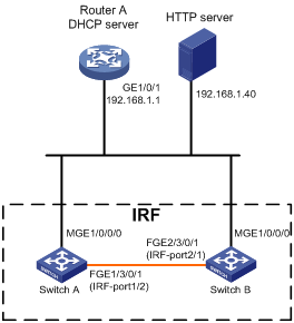
Configuration procedure
1. Assign IP addresses to the interfaces. Make sure the devices can reach each other. (Details not shown.)
2. Configure the following files on the HTTP server:
|
File |
Content |
Remarks |
|
.cfg configuration file |
Commands required for IRF setup. |
You can create a configuration file by modifying the configuration file exported from an existing IRF fabric. |
|
sn.txt |
Serial numbers of the member switches. |
Each SN uniquely identifies a switch. These SNs will be used for assigning a unique IRF member ID to each member switch. |
|
(Optional.) .ipe or .bin software image file |
Software images. |
If the member switches are running different software versions, you must prepare the software image file used for software upgrade. |
|
.py Python script files |
Python commands and APIs that complete the following tasks: a (Optional.) Verifies that the flash memory has sufficient space for the files to be downloaded. b Downloads the configuration file, sn.txt, and the software image file. c Sets the software image file as the main startup image file. d Assigns a unique IRF member ID to each SN. e Sets the configuration file as the main next-startup configuration file. f Reboots the member switches. |
Create a Python script file for each member switch. For more information about Python script configuration, see "Using Python." |
3. Configure the DHCP server:
# Enable DHCP.
<RouterA> system-view
[RouterA] dhcp enable
# Configure the address pool 1 to assign IP addresses on subnet 192.168.1.0/24 to clients.
[RouterA] dhcp server ip-pool 1
[RouterA-dhcp-pool-1] network 192.168.1.0 24
# Specify the URL of the script file for the clients.
[RouterA-dhcp-pool-1] bootfile-name http://192.168.1.40/device.py
4. Power on Switch A and Switch B.
Switch A and Switch B will obtain a Python script file from the DHCP server and execute the script. Then, Switch A and Switch B will reboot.
5. After Switch A and Switch B start up again, use a cable to connect Switch A and Switch B through their IRF physical ports.
Switch A and Switch B will elect a master. The subordinate will reboot to join the IRF fabric.
Verifying the configuration
# Display IRF fabric information.
<Switch A>display irf
MemberID Slot Role Priority CPU-Mac Description
1 1 Standby 1 00e0-fc0f-8c02 ---
*+2 1 Master 30 00e0-fc0f-8c14 ---
--------------------------------------------------
* indicates the device is the master.
+ indicates the device through which the user logs in.
The Bridge MAC of the IRF is: 000c-1000-1111
Auto upgrade : yes
Mac persistent : always
Domain ID : 0
Auto merge : yes
The output shows that the switches have formed an IRF fabric.
Configuring preprovisioning
Overview
Preprovisioning allows you to preconfigure interfaces on an offline module. In this release, interface cards can be preprovisioned.
With preprovisioning, you can configure a module before installing or attaching the module to the device. The preprovisioned settings are applied when the module comes online.
You can also enable preprovisioning for an online module and configure the module. The settings take effect immediately. After the module goes offline, the existing preprovisioned settings are retained and you can continue to change the existing settings or add new settings. The final settings are applied when the module comes online again.
Feature and software version compatibility
This feature is available in Release 1138P01 and later versions.
Enabling preprovisioning
The device automatically creates interfaces when preprovisioning is enabled for a module. The display interface command does not display these interfaces until the module comes online.
After preprovisioning is enabled for a module, you can configure the module and its interfaces. To verify the preprovisioned settings, see "Displaying and maintaining preprovisioned settings." For the preprovisioned settings to survive a reboot, you must use the save command to save the settings to the next-startup configuration file.
When you disable preprovisioning for a slot, the device removes all preprovisioned commands from the slot.
To enable preprovisioning for a slot:
|
Step |
Command |
Remarks |
|
1. Enter system view. |
system-view |
N/A |
|
2. Select the slot to preprovision and enter slot view. |
·
In standalone mode: ·
In IRF mode: |
N/A |
|
3. Enable preprovisioning for the slot. |
provision model model |
By default, preprovisioning is disabled. You must make sure the specified model matches the model of the interface card you want to preprovision. If the model information does not match, the interface card cannot come online. |
Displaying and maintaining preprovisioned settings
Execute display commands in any view.
|
Task |
Command |
Remarks |
|
Display the preprovisioned commands that were not applied to preprovisioned modules that came online. |
display provision failed-config |
After preprovisioned modules come online, you can use this command to determine the application result of preprovisioned settings. A preprovisioned command cannot be applied if it conflicts with the running configuration. |
|
Clear application failure records for preprovisioned commands. |
reset provision failed-config |
N/A |
A
AAA
RBAC AAA authorization, 47
RBAC default user role, 52
RBAC local AAA authentication user configuration, 56
RBAC user role local AAA authentication, 53
RBAC user role non-AAA authentication, 53
RBAC user role remote AAA authentication, 52
abbreviating command, 4
accessing
CLI online help, 2
login management SNMP device access, 35
MDC, 147
RBAC VPN instance access policy, 46
accounting
login management command accounting, 42, 43
login management user access control, 37
ACL
login management command authorization, 40, 41
login management SNMP access control, 38, 39
login management SSH login control, 37
login management Telnet login control, 37, 37
login management user access control, 37
acquiring
automatic configuration file acquisition process, 173
automatic configuration parameter acquisition process, 173
activating
license, 167
active
FTP active (PORT) operating mode, 66
software upgrade MPU synchronization, 106
adjusting
ISSU running configuration, 113
alias (CLI command keyword), 5
API
extended Python API, 160
extended Python API functions, 160
application
MDC, 140
argument (CLI string/text type), 4
ASCII transfer mode, 66
assigning
CLI user line assignment, 19
MDC hardware resources, 142
MDC physical interface, 142
RBAC local AAA authentication user role, 53
RBAC non-AAA authentication user role, 53
RBAC permission assignment, 45
RBAC remote AAA authentication user role, 52
RBAC user role, 52
RBAC user role assignment, 47
authenticating
FTP basic server authentication, 67
login management CLI console/AUX none authentication, 21
login management CLI console/AUX password authentication, 22
login management CLI console/AUX scheme authentication, 22
login management CLI none authentication mode, 19
login management CLI password authentication mode, 19
login management CLI scheme authentication mode, 19
login management Telnet login none authentication, 26
login management Telnet login password authentication, 27
login management Telnet login scheme authentication, 28
RBAC HWTACACS authentication user configuration, 61
RBAC local AAA authentication user configuration, 56
RBAC RADIUS authentication user configuration, 58
RBAC user role authentication, 55
RBAC user role local AAA authentication, 53
RBAC user role remote AAA authentication, 52
authorizing
FTP basic server authorization, 67
login management command authorization, 40, 41
login management user access control, 37
MDC LPU use, 142
RBAC temporary user role authorization, 54
auto
configuration. See automatic configuration
configuration file acquisition process, 173
feature, 170
interface selection process, 172
parameter acquisition process, 173
process, 170
server configuration, 175
server deployment, 175
AUX
console/AUX common user line settings, 23
console/AUX none authentication, 21
console/AUX password authentication, 22
console/AUX scheme authentication, 22
login management CLI local console/AUX port login, 20
login management overview, 15
B
backing up
main next-startup configuration file, 95
software upgrade backup image set, 98
banner
configuration, 120, 122
incoming type, 120
legal type, 120
login type, 120
MOTD type, 120
multiple-line input mode, 121
shell type, 120
single-line input mode, 121
binary transfer mode, 66
boot loader
startup image file specification (in IRF mode), 104
startup image file specification (in standalone mode), 102
Boot ROM
software upgrade image type, 98, 98
software upgrade methods, 100
software upgrade preparation, 101
software upgrade system startup, 99
BootWare
BootWare image preload, 102
image downgrade, 106
image restore, 106
startup image file specification (in IRF mode), 104
startup image file specification (in standalone mode), 102
C
calculating
file digest, 83
card
MDC LPU authorization, 142
CF card partitioning, 86
changing
file system current working directory, 84
FTP user account, 73
command abbreviation, 4
command entry, 3
command history function use, 7
command hotkey use, 6
command keyword alias configuration, 5
command keyword alias use, 5
command keyword hotkey configuration, 6
command line editing, 4
command redisplay, 7
command-line error message, 7
console port login procedure, 16
console/AUX common user line settings, 23
console/AUX none authentication, 21
console/AUX password authentication, 22
console/AUX scheme authentication, 22
device reboot (immediate), 124
device reboot (scheduled), 124
display command output filtering, 10
display command output line numbering, 9
display command output management, 13
display command output save to file, 12
display command output viewing, 13
displaying login, 33
enter system view from user view, 2
local console/AUX port login, 20
login authentication modes, 19
login management overview, 15
login overview, 19
maintaining login, 33
online help access, 2
output control, 8
output control keys, 9
return to upper-level view from any view, 2
return to user view, 2
running configuration save, 14
software upgrade, 98
string/text type argument value, 4
undo command form, 3
use, 1
user lines, 19
user roles, 20
view hierarchy, 1
client
FTP client configuration (IRF mode), 76
FTP client configuration (standalone mode), 74
IPv4 TFTP client configuration, 78
command
CLI command abbreviation, 4
CLI command entry, 3
CLI command history function use, 7
CLI command hotkey configuration, 6
CLI command hotkey use, 6
CLI command keyword alias configuration, 5
CLI command keyword alias use, 5
CLI command line editing, 4
CLI command redisplay, 7
CLI string/text type argument value, 4
CLI undo command form, 3
ISSU, 110
ISSU device operating status verification, 112
ISSU feature status verification, 112
ISSU upgrade image preparation, 112
line interface. Use CLI
login management command accounting, 42, 43
login management command authorization, 40, 41
Python, 158, 158
commit delay
running configuration, 94
completing
software upgrade (in IRF mode), 104
software upgrade (in standalone mode), 102
compressing
file, 82, 82
license management storage, 168
Comware
software upgrade Boot image type, 98
software upgrade feature image, 98
software upgrade image loading, 98
software upgrade image redundancy, 98
software upgrade image type, 98
software upgrade patch image, 98
software upgrade system image type, 98
configuration
startup configuration loading, 88
configuration file
automatic acquisition process, 173
configuration difference display, 91
content, 90
device configuration types, 88
displaying, 97
encryption, 91
file formats, 89
FIPS compliance, 90
format, 90
main next-startup file backup, 95
main next-startup file restore, 95
management, 88
next-startup configuration file, 94
next-startup file delete, 96
restrictions and guidelines, 90
running configuration save, 92, 93
startup file selection, 90
configuring
automatic configuration, 170
CLI command keyword alias, 5
command keyword hotkey, 6
configuration commit delay, 94
device as IPv4 TFTP client, 78
device banner, 120, 122
device name, 119
device system time, 119
device temperature alarm threshold, 133
FTP, 66
FTP basic server parameters, 66
FTP client (IRF mode), 76
FTP client (standalone mode), 74
FTP server (IRF mode), 69
FTP server (standalone mode), 68
FTP server authentication, 67
FTP server authorization, 67
global on-demand diagnostics, 134
login management CLI console/AUX common user line settings, 23
login management CLI console/AUX none authentication, 21
login management CLI console/AUX password authentication, 22
login management CLI console/AUX scheme authentication, 22
login management CLI local console/AUX port login, 20
login management command accounting, 42, 43
login management command authorization, 40, 41
login management common VTY line settings, 29
login management SNMP access control, 39
login management SNMPv1 access, 36
login management SNMPv2 access, 36
login management SNMPv3 access, 35
login management SSH login, 31
login management SSH login on device, 31
login management Telnet login, 25
login management Telnet login on device, 25
login management Telnet login password authentication, 27
login management Telnet login scheme authentication, 28
MDC, 140, 141, 148, 151
preprovisioning, 179
RBAC, 45, 48, 56
RBAC feature group, 50
RBAC for HWTACACS authentication user, 61
RBAC for RADIUS authentication user, 58
RBAC local AAA authentication user, 56
RBAC resource access policies, 50
RBAC temporary user role authorization, 54
RBAC user role authentication, 55
RBAC user role interface policy, 51
RBAC user role rules, 49
RBAC user role VLAN policy, 51
RBAC user role VPN instance policy, 51
TFTP, 78
user process maintenance parameter, 136
console
login management CLI console/AUX common user line settings, 23
login management CLI console/AUX none authentication, 21
login management CLI console/AUX password authentication, 22
login management CLI console/AUX scheme authentication, 22
login management CLI local console/AUX port login, 20
login management console port login procedure, 16
login management overview, 15
content
configuration difference display, 91
controlling
CLI output, 8
CLI output control keys, 9
login management SNMP access, 38
login management SSH logins, 37
login management Telnet logins, 37, 37
login management user access, 37
RBAC configuration, 45, 48
copying
file, 81
copyright statement display, 120
CPU
ISSU methods, 111
MDC CPU weight, 145
CPU usage
monitoring, 130
creating
file system directory, 84
MDC, 142
RBAC user role, 48
D
days-restricted license, 166
decompressing
file, 82, 82
default
MDC, 141
deleting
file, 82
next-startup configuration file, 96
recycle bin file, 83
detecting
device port status detection timer, 130
device
automatic configuration, 170
automatic configuration server configuration, 175
automatic configuration server deployment, 175
CLI command history function use, 7
CLI command redisplay, 7
CLI display command output filtering, 10
CLI display command output line numbering, 9
CLI display command output management, 13
CLI display command output save to file, 12
CLI display command output viewing, 13
CLI output control, 8, 9
CLI running configuration save, 14
CLI use, 1
command help information display, 74
default MDC, 141
enter system view from user view, 2
file system management, 79
file system storage media formatting, 85
file system storage media management, 85
file system storage media mount, 86
file system storage media repair, 85
file system storage media unmount, 86
FTP basic server parameters configuration, 66
FTP client, 71
FTP client configuration (IRF mode), 76
FTP client configuration (standalone mode), 74
FTP client connection establishment, 71
FTP configuration, 66
FTP connection termination, 74
FTP connection troubleshooting, 73
FTP manual server connection release, 67
FTP server, 66
FTP server authentication, 67
FTP server authorization, 67
FTP server configuration (IRF mode), 69
FTP server configuration (standalone mode), 68
FTP server directory management, 72
FTP server files, 72
FTP user account change, 73
IPv4 TFTP client configuration, 78
license management, 166
license management (device locked), 166
license management activation, 167
license management registration, 167
license management storage compression, 168
license management transfer, 167
login management SNMP device access, 35
login management SSH login configuration on device, 31
login management SSH server login, 33
login management Telnet login device configuration, 25
login management Telnet server login, 31
MDC access, 147
MDC application, 140
MDC configuration, 140, 141, 148, 151
MDC CPU weight specification, 145
MDC creation, 142
MDC hardware resource assignment, 142
MDC LPU authorization, 142
MDC physical interface assignment, 142
MDC start, 146
multitenant device context. Use MDC
non-default MDC, 141
preprovisioning configuration, 179
recovering licenses, 169
return to upper-level view from any view, 2
return to user view, 2
software upgrade, 98
software upgrade system startup, 99
specifying MDC memory space percentage, 146
storage media CF card partition, 86
storage media USB disk partition, 86
TFTP configuration, 78
banner configuration, 120, 122
banner input modes, 121
banner types, 120
configuration, 119
copyright statement display, 120
device name configuration, 119
device reboot, 123
device reboot (immediate), 124
device reboot (scheduled), 124
global on-demand diagnostics, 134
memory usage threshold, 131
monitoring CPU usage, 130
password recovery capability disable, 130
port status detection timer, 130
switching fabric module isolate, 134
system operating mode, 122, 122
system time configuration, 119
system time set, 119
system time source set, 119
task scheduling, 124, 126
TCAM operating mode, 123
temperature alarm threshold, 133
transceiver module diagnosis, 135
transceiver module verification, 135, 135
user process maintenance parameter, 136
device-locked
activating licenses, 167
compressing licenses, 168
displaying licenses, 169
maintaining licenses, 169
recovering licenses, 169
registering licenses, 167
transfering licenses, 167
DHCP
automatic configuration, 170
automatic configuration parameter acquisition process, 173
automatic configuration server configuration, 175
automatic configuration server deployment, 175
diagnosing
device transceiver modules, 135
directory
file system current working directory change, 84
file system current working directory display, 84
file system directory creation, 84
file system directory information display, 84
file system directory management, 83
file system directory removal, 84
file system management, 79
FTP server directory management, 72
disabling
CLI output screen pausing, 9
device password recovery capability, 130
login management Telnet login authentication, 26
displaying
CLI login, 33
command help information, 74
configuration differences, 91
configuration files, 97
device copyright statement, 120
device management configuration, 136
file system current working directory display, 84
file system directory information, 84
file system file information, 81
file system text file content, 81
FTP client, 74
FTP server, 67
ISSU, 115
license, 169
MDC, 147
preprovisioned settings, 180
RBAC settings, 56
software upgrade image settings, 107
DNS
automatic configuration, 170
automatic configuration server configuration, 175
automatic configuration server deployment, 175
downgrading
BootWare image, 106
E
editing command line, 4
emergency shell
software upgrade (Comware), 98
enabling
CLI command redisplay, 7
configuration encryption, 91
CPU usage monitoring, 130
device copyright statement display, 120
preprovisioning, 179
RBAC default user role, 52
software upgrade MPU synchronization, 106
encrypting
private key, 91
public key, 91
entering
CLI entered-but-not-submitted command redisplay, 7
command, 3
string/text type argument value, 4
system view from user view, 2
error
CLI command line error message, 7
establishing
FTP client connection, 71
F
fast saving running configuration, 92, 93
feature
license management, 166
file
calculating digest, 83
compression, 82, 82
configuration difference display, 91
configuration file content, 90
configuration file format, 90
configuration file formats, 89
configuration file management, 88
copying, 81
decompression, 82, 82
deleting from recycle bin, 83
deletion, 82
device configuration startup file selection, 90
FTP server files, 72
information display, 81
license management activation, 167
license management registration, 167
license management transfer, 167
management, 81
moving, 82
name format, 79
next-startup configuration file, 94
renaming, 81
restoration, 82
software upgrade file naming, 98
system. See file system
text content display, 81
current working directory change, 84
current working directory display, 84
directory creation, 84
directory information display, 84
directory management, 83
directory removal, 84
file compression, 82, 82
file copy, 81
file decompression, 82, 82
file deletion, 82
file digest calculation, 83
file information display, 81
file management, 81
file move, 82
file name formats, 79
file rename, 81
file restoration, 82
file/folder operation mode, 87
management, 79
recycle bin file delete, 83
storage media CF card partition, 86
storage media CF card partitioning restrictions, 86
storage media formatting, 85
storage media management, 85
storage media mount, 86
storage media mounting/unmounting restrictions, 86
storage media naming rules, 79
storage media repair, 85
storage media unmount, 86
storage media USB disk partition, 86, 86
text file content display, 81
File Transfer Protocol. Use FTP
filtering
CLI display command output, 10
FIPS compliance
configuration file, 90
RBAC, 48
format
configuration file, 89, 90
file name, 79
file system storage media formatting, 85
basic server parameters configuration, 66
client configuration (IRF mode), 76
client configuration (standalone mode), 74
client connection establishment, 71
command help information display, 74
configuration, 66
connection maintenance, 73
connection termination, 74
device as client, 71
device as server, 66
displaying client, 74
displaying server, 67
IPv4 TFTP client configuration, 78
local server authentication, 67
local server authorization, 67
manual server connection release, 67
remote server authentication, 67
remote server authorization, 67
server configuration (IRF mode), 69
server configuration (standalone mode), 68
server directory management, 72
server files, 72
TFTP configuration, 78
troubleshooting connection, 73
user account change, 73
G
global on-demand diagnostics, 134
group
RBAC feature group configuration, 50
guidelines
managing licenses, 166
H
hardware
MDC physical interface assignment, 142
MDC resource assignment, 142
history
CLI history function, 7
hotkey (command), 6
HWTACACS
login management command accounting, 42, 43
RBAC HWTACACS authentication user configuration, 61
I
identifying
CLI user line, 19
ISSU availability, 111
image
BootWare image downgrade, 106
BootWare image restore, 106
ISSU patch image, 114
ISSU patch image uninstalling, 114
software upgrade Boot ROM image type, 98
software upgrade Comware Boot image type, 98
software upgrade Comware image loading, 98
software upgrade Comware image redundancy, 98
software upgrade Comware image type, 98
software upgrade Comware system image type, 98
startup image file specification (in IRF mode), 104
startup image file specification (in standalone mode), 102
Import
extended Pythond API, 160
incoming banner type, 120
In-Service Software Upgrade. Use ISSU
installing
ISSU patch images, 114
interface, 15, See also line
interface card
preprovisioning configuration, 179
IP
FTP configuration, 66
TFTP configuration, 78
IPv4
FTP client connection establishment, 71
TFTP client configuration, 78
IPv6
FTP client connection establishment, 71
IRF
BootWare image preload, 102, 102
FTP client configuration (IRF mode), 76
FTP server configuration (IRF mode), 69
ISSU, 110, 113, 115
ISSU device operating status verification, 112
ISSU feature status verification, 112
ISSU methods, 111
ISSU upgrade image preparation, 112
software upgrade (IRF mode), 108
software upgrade completion (in IRF mode), 104
software upgrade startup image file specification (in IRF mode), 104
isolating
switching fabric module, 134
adjusting running configuration, 113
console port login, 113
displaying, 115
maintaining, 115
methods, 111
patch image, 114
patch image uninstalling, 114
saving running configuration, 113
software upgrade Comware image method, 100
software upgrade non-ISSU method, 100
upgrade restrictions, 112
K
key
command hotkey, 6
keyword alias configuration (CLI), 5
L
LAN
default MDC, 141
MDC application, 140
MDC configuration, 140, 141, 148, 151
MDC creation, 142
non-default MDC, 141
legal banner type, 120
license management
activation, 167
days-restricted license, 166
displaying license, 169
feature use, 166
guidelines and restrictions, 166
permanent license, 166
registration, 167
storage compression, 168
transfer, 167
CLI user line assignment, 19
login management CLI console/AUX common user line settings, 23
login management CLI user line, 19
login management CLI user line identification, 19
login management VTY common line settings, 29
local
RBAC local AAA authentication user configuration, 56
RBAC user role local AAA authentication, 53
logging in
ISSU console port, 113
login management CLI console/AUX common user line settings, 23
login management CLI console/AUX none authentication, 21
login management CLI console/AUX password authentication, 22
login management CLI console/AUX scheme authentication, 22
login management CLI local console/AUX port login, 20
login management CLI login, 19
login management CLI login authentication modes, 19
login management CLI user lines, 19
login management CLI user roles, 20
login management console port login, 16
login management SSH login, 31
login management SSH login configuration on device, 31
login management SSH server login, 33
login management Telnet login, 25
login management Telnet login device configuration, 25
login management Telnet login max number concurrent users, 29
login management Telnet login none authentication, 26
login management Telnet login password authentication, 27
login management Telnet login scheme authentication, 28
login management Telnet server login, 31
login management VTY common line settings, 29
login
device banner login type, 120
login management
CLI access, 19
CLI console/AUX common user line settings, 23
CLI console/AUX none authentication, 21
CLI console/AUX password authentication, 22
CLI console/AUX scheme authentication, 22
CLI local console/AUX port login, 20
CLI login authentication modes, 19
CLI user line assignment, 19
CLI user line identification, 19
CLI user roles, 20
console port access, 16
displaying CLI login, 33
DSCP value for outgoing Telnet packet, 29
maintaining CLI login, 33
overview, 15
SNMP access control, 39
SNMP device access, 35
SNMPv1 access configuration, 36
SNMPv2 access configuration, 36
SNMPv3 access configuration, 35
SSH login, 31
SSH login control, 37
SSH login on device, 31
SSH server login, 33
Telnet login, 25
Telnet login control, 37, 37
Telnet login device configuration, 25
Telnet login max number concurrent users, 29
Telnet login none authentication, 26
Telnet login password authentication, 27
Telnet login scheme authentication, 28
Telnet server login, 31
user access control, 37
user lines, 19
VTY common line settings, 29
M
main
software upgrade image set, 98
main next-startup configuration file, 95, 95
maintaining
CLI login, 33
device management configuration, 136
FTP connection, 73
ISSU, 115
RBAC settings, 56
software upgrade image settings, 107
managing
CLI display command output, 13
configuration files, 88
device. See device management
file system, 79
file system directories, 83
file system files, 81
file system storage media, 85
FTP server directories, 72
manual
FTP server connection release, 67
access, 147
application, 140
configuration, 140, 141, 148, 151
CPU weight specification, 145
creation, 142
default MDC, 141
displaying, 147
hardware resource assignment, 142
LPU authorization, 142
memory space percentage specification, 146
non-default MDC, 141
physical interface assignment, 142
start, 146
memory
device memory usage threshold, 131
MDC memory space percentage, 146
message
CLI command line error message, 7
message-of-the-day (MOTD) banner type, 120
MIB
login management SNMP device access, 35
mode
device system operating mode, 122, 122
device TCAM operating mode, 123
file system file/folder alert operation mode, 87
file system file/folder quiet operation mode, 87
FTP active (PORT) operating mode, 66
FTP ASCII transfer mode, 66
FTP binary transfer mode, 66
FTP passive (PASV) operating mode, 66
login management none CLI authentication, 19
login management password CLI authentication, 19
login management scheme CLI authentication, 19
modem
login management overview, 15
module
device transceiver module diagnosis, 135
device transceiver module verification, 135, 135
preprovisioning configuration, 179
monitoring
CPU usage, 130
mounting
file system storage media, 86
moving
file, 82
MPU
ISSU device operating status verification, 112
ISSU feature status verification, 112
ISSU methods, 111
ISSU upgrade image preparation, 112
license management (MPU locked), 166
software upgrade synchronization, 106
multiple-line banner input mode, 121
multitenant device context. Use MDC
N
naming
device name configuration, 119
file name formats, 79
file rename, 81
software upgrade files, 98
storage media naming rules, 79
network
automatic configuration file acquisition process, 173
automatic configuration parameter acquisition process, 173
automatic configuration server configuration, 175
automatic configuration server deployment, 175
command help information display, 74
default MDC, 141
device as FTP client, 71
device as FTP server, 66
device banner configuration, 120
device banner input modes, 121
device banner types, 120
device copyright statement display, 120
device management task scheduling, 124, 126
device memory usage threshold, 131
device name configuration, 119
device password recovery capability disable, 130
device port status detection timer, 130
device reboot, 123
device reboot (immediate), 124
device reboot (scheduled), 124
device system operating mode, 122, 122
device system time configuration, 119
device system time set, 119
device system time source set, 119
device TCAM operating mode, 123
device temperature alarm threshold, 133
device transceiver module diagnosis, 135
device transceiver module verification, 135, 135
file system directory management, 83
file system file management, 81
file system storage media management, 85
FTP basic server parameters configuration, 66
FTP client configuration (IRF mode), 76
FTP client configuration (standalone mode), 74
FTP client connection establishment, 71
FTP connection termination, 74
FTP connection troubleshooting, 73
FTP manual server connection release, 67
FTP server authentication, 67
FTP server authorization, 67
FTP server configuration (IRF mode), 69
FTP server configuration (standalone mode), 68
FTP server directory management, 72
FTP server files, 72
FTP user account change, 73
global on-demand diagnostics, 134
IPv4 TFTP client configuration, 78
ISSU, 113
ISSU availability identification, 111
ISSU device operating status verification, 112
ISSU feature status verification, 112
ISSU methods, 111
ISSU patch image, 114
ISSU patch image uninstalling, 114
ISSU preparation, 111
ISSU upgrade image preparation, 112
login management command accounting, 42, 43
login management command authorization, 40, 41
login management SNMP access control, 38, 39
login management SNMPv1 access configuration, 36
login management SNMPv2 access configuration, 36
login management SNMPv3 access configuration, 35
login management SSH login control, 37
login management Telnet login control, 37, 37
MDC access, 147
MDC application, 140
MDC CPU weight specification, 145
MDC creation, 142
MDC hardware resources assignment, 142
MDC LPU authorization, 142
MDC physical interface assignment, 142
MDC start, 146
monitoring CPU usage, 130
non-default MDC, 141
preprovisioning enable, 179
RBAC default user role, 52
RBAC feature group configuration, 50
RBAC permission assignment, 45
RBAC resource access policies, 50
RBAC temporary user role authorization, 54, 56
RBAC user role assignment, 47, 52
RBAC user role authentication, 55
RBAC user role creation, 48
RBAC user role interface policy, 51
RBAC user role local AAA authentication, 53
RBAC user role non-AAA authentication, 53
RBAC user role remote AAA authentication, 52
RBAC user role rule configuration, 49
RBAC user role VLAN policy, 51
RBAC user role VPN instance policy, 51
switching fabric module isolate, 134
user process maintenance parameter, 136
network management
automatic configuration, 170
CLI use, 1
configuration file management, 88
device management, 119
extended Python API, 160
extended Python API functions, 160
extended Python API import, 160
extended Python API use, 160
file system management, 79
FTP configuration, 66
ISSU, 110, 115
ISSU flow chart, 111
license management, 166
login management SNMP device access, 35
login management user access control, 37
MDC configuration, 140, 141, 148, 151
preprovisioning configuration, 179
Python use, 158, 158
RBAC configuration, 45, 48, 56
RBAC HWTACACS authentication user configuration, 61
RBAC local AAA authentication user configuration, 56
RBAC RADIUS authentication user configuration, 58
software upgrade, 98
software upgrade (for standalone mode), 107
software upgrade (IRF mode), 108
TFTP configuration, 78
next-startup configuration file, 96
NMS
login management SNMP device access, 35
non-AAA authentication (RBAC), 53
non-AAA authorization (RBAC), 47
non-default MDC, 141
none
login management CLI authentication mode, 19
login management CLI console/AUX none authentication, 21
login management Telnet login none authentication, 26
numbering
CLI display command output lines, 9
O
obtaining
RBAC temporary user role authorization, 56
online
CLI online help access, 2
Option 150 (DHCP)
automatic configuration parameter acquisition process, 173
Option 6 (DHCP);Option 006
automatic configuration parameter acquisition process, 173
Option 66 (DHCP);Option 066
automatic configuration parameter acquisition process, 173
Option 67 (DHCP);Option 067
automatic configuration parameter acquisition process, 173
outputting
CLI display command output filtering, 10
CLI display command output management, 13
CLI display command output view, 13
CLI display comment output to file, 12
CLI output control, 8
CLI output control keys, 9
CLI output line numbering, 9
P
parameter
automatic configuration parameter acquisition process, 173
device management, 119
FTP basic server parameters configuration, 66
partitioning
storage media CF card partition, 86
storage media USB disk, 86
passive
FTP passive (PASV) operating mode, 66
password
device password recovery capability disable, 130
login management CLI authentication mode, 19
login management CLI console/AUX password authentication, 22
login management Telnet login password authentication, 27
login management Telnet login scheme authentication, 28
patch
software upgrade Comware patch image, 98
patching
ISSU software images, 114
pausing between CLI output screens, 8
performing
ISSU, 110, 113, 115
permanent license, 166
permitting
RBAC permission assignment, 45
RBAC user role assignment, 47
PEX
preprovisioning configuration, 179
policy
RBAC interface access policy, 46
RBAC resource access policies, 50
RBAC user role assignment, 52
RBAC user role interface policy, 51
RBAC user role local AAA authentication, 53
RBAC user role non-AAA authentication, 53
RBAC user role remote AAA authentication, 52
RBAC user role VLAN policy, 51
RBAC user role VPN instance policy, 51
RBAC VLAN access policy, 46
RBAC VPN instance access policy, 46
port
device status detection timer, 130
preloading
BootWare image, 102
preparing
ISSU, 111
ISSU upgrade image, 112
software upgrade (non-ISSU), 101
preprovisioning
configuration, 179
enable, 179
settings display, 180
procedure
abbreviating CLI command, 4
accessing CLI online help, 2
accessing MDC, 147
activating license, 167
assigning MDC hardware resources, 142
assigning MDC physical interface, 142
assigning RBAC local AAA authentication user role, 53
assigning RBAC non-AAA authentication user role, 53
assigning RBAC remote AAA authentication user role, 52
assigning RBAC user role, 52
authorizing MDC to use LPU, 142
backing up main next-startup configuration file, 95
calculating file digest, 83
changing current working directory, 84
changing FTP user accounts, 73
completing software upgrade (in IRF mode), 104
completing software upgrade (in standalone mode), 102
compressing file, 82, 82
compressing license storage, 168
configuring CLI command hotkey, 6
configuring CLI command keyword alias, 5
configuring configuration commit delay, 94
configuring device as IPv4 TFTP client, 78
configuring device banner, 120, 122
configuring device name, 119
configuring device system time, 119
configuring device temperature alarm threshold, 133
configuring FTP basic server parameters, 66
configuring FTP client (IRF mode), 76
configuring FTP client (standalone mode), 74
configuring FTP server (IRF mode), 69
configuring FTP server (standalone mode), 68
configuring FTP server local authentication, 67
configuring FTP server local authorization, 67
configuring FTP server remote authentication, 67
configuring FTP server remote authorization, 67
configuring global on-demand diagnostics, 134
configuring login management CLI console/AUX common user line settings, 23
configuring login management CLI console/AUX password authentication, 22
configuring login management CLI console/AUX scheme authentication, 22
configuring login management CLI local console/AUX port login, 20
configuring login management command accounting, 42, 43
configuring login management command authorization, 40, 41
configuring login management SNMP access control, 39
configuring login management SNMPv1 access, 36
configuring login management SNMPv2 access, 36
configuring login management SNMPv3 access, 35
configuring login management SSH login, 31
configuring login management SSH login on device, 31
configuring login management Telnet login, 25
configuring login management Telnet login on device, 25
configuring login management Telnet login password authentication, 27
configuring login management Telnet login scheme authentication, 28
configuring login management VTY common line settings, 29
configuring MDC, 148, 151
configuring RBAC, 48, 56
configuring RBAC feature group, 50
configuring RBAC for HWTACACS authentication user, 61
configuring RBAC for RADIUS authentication user, 58
configuring RBAC local AAA authentication user, 56
configuring RBAC resource access policies, 50
configuring RBAC temporary user role authorization, 54
configuring RBAC user role authentication, 55
configuring RBAC user role interface policy, 51
configuring RBAC user role rules, 49
configuring RBAC user role VLAN policy, 51
configuring RBAC user role VPN instance policy, 51
configuring user process maintenance parameter, 136
controlling CLI output, 8, 9
controlling login management SNMP access, 38
controlling login management SSH logins, 37
controlling login management Telnet logins, 37, 37
copying file, 81
creating directory, 84
creating MDC, 142
creating RBAC user role, 48
decompressing file, 82, 82
deleting file, 82
deleting file from recycle bin, 83
deleting next-startup configuration file, 96
diagnosing device transceiver module, 135
disabling CLI console/AUX authentication, 21
disabling CLI output screen pausing, 9
disabling device password recovery capability, 130
disabling login management Telnet login authentication, 26
displaying CLI login, 33
displaying command help information, 74
displaying configuration files, 97
displaying current working directory, 84
displaying device management configuration, 136
displaying directory information, 84
displaying file information, 81
displaying FTP client, 74
displaying FTP server, 67
displaying ISSU, 115
displaying license, 169
displaying MDCs, 147
displaying preprovisioned settings, 180
displaying RBAC settings, 56
displaying software upgrade image settings, 107
displaying text file content, 81
downgrading BootWare image, 106
editing CLI command line, 4
enabling CLI redisplay of entered-but-not-submitted command, 7
enabling configuration encryption, 91
enabling device copyright statement display, 120
enabling preprovisioning, 179
enabling RBAC default user role, 52
enabling software upgrade MPU synchronization, 106
entering CLI command, 3
entering CLI string/text type argument value, 4
entering Python shell, 158
entering system view from user view, 2
establishing FTP client connection, 71
executing Python script, 158
exiting Python shell, 158
filtering CLI display command output, 10
formatting file system storage media, 85
installing ISSU patch images, 114
isolating switching fabric module, 134
logging in to SSH server (device login), 33
logging in to Telnet server (device login), 31
maintaining CLI login, 33
maintaining device management configuration, 136
maintaining FTP connection, 73
maintaining ISSU, 115
maintaining RBAC settings, 56
maintaining software upgrade image settings, 107
managing CLI display command output, 13
managing file system directories, 83
managing file system files, 81
managing file system storage media, 85
managing FTP server directories, 72
manually releasing FTP server connection, 67
monitoring CPU usage, 130
mounting file system storage media, 86
moving file, 82
numbering CLI display command output lines, 9
obtaining RBAC temporary user role authorization, 56
partitioning CF card, 86
partitioning USB disk, 86
pausing between CLI output screens, 8
performing ISSU, 113, 115
preloading BootWare image, 102
preparing for software upgrade (non-ISSU), 101
preparing ISSU upgrade image, 112
rebooting device, 123
rebooting device (immediate), 124
rebooting device (scheduled), 124
recovering license, 169
registering license, 167
removing directory, 84
renaming file, 81
repairing file system storage media, 85
restoring BootWare image, 106
restoring file, 82
restoring main next-startup configuration file, 95
returning to upper-level view from any view, 2
returning to user view, 2
saving CLI display command output to file, 12
saving CLI running configuration, 14
saving running configuration, 92, 93
scheduling device management task, 124, 126
setting device memory usage threshold, 131
setting device port status detection timer, 130
setting device system operating mode, 122, 122
setting device system time, 119
setting DSCP value for outgoing Telnet packet, 29
setting file/folder operation mode, 87
setting login management Telnet login max number concurrent users, 29
setting TCAM operating mode, 123
specifying device system time source, 119
specifying MDC CPU weight, 145
specifying MDC memory space percentage, 146
specifying next-startup configuration file, 94
specifying startup image file (in IRF mode), 104
specifying startup image file (in standalone mode), 102
starting MDC, 146
terminating FTP connection, 74
transferring license, 167
troubleshooting FTP connection, 73
troubleshooting RBAC local user access permissions, 64
troubleshooting RBAC login attempts by RADIUS users fail, 65
understanding CLI command-line error message, 7
uninstalling ISSU patch images, 114
unmounting file system storage media, 86
upgrading software, 101
upgrading software (for standalone mode), 107
upgrading software (IRF mode), 108
using CLI command history function, 7
using CLI command hotkey, 6
using CLI command keyword alias, 5
using CLI undo command form, 3
using Python, 158
verifying device transceiver module, 135, 135
verifying ISSU device operating status, 112
viewing CLI display command output, 13
working with FTP server files, 72
Python
extended API, 160
extended API functions, 160
script, 158
shell, 158, 158
use, 158, 158
R
RADIUS
RBAC RADIUS authentication user configuration, 58
AAA authorization, 47
configuration, 45, 48, 56
default user role, 52
displaying settings, 56
feature group configuration, 50
FIPS compliance, 48
HWTACACS authentication user configuration, 61
local AAA authentication user configuration, 56
maintaining settings, 56
non-AAA authorization, 47
permission assignment, 45
predefined user roles, 46
RADIUS authentication user configuration, 58
resource access policies, 46, 50
rule configuration restrictions, 49
temporary user role authorization, 56
temporary user role authorization configuration, 54
troubleshooting, 64
troubleshooting local user access permissions, 64
troubleshooting login attempts by RADIUS users fail, 65
user role assignment, 47, 52
user role authentication, 55
user role creation, 48
user role interface policy, 51
user role local AAA authentication, 53
user role non-AAA authentication, 53
user role remote AAA authentication, 52
user role rule configuration, 49
user role rules, 45
user role VLAN policy, 51
user role VPN instance policy, 51
rebooting
device, 123
device (immediate), 124
device (scheduled), 124
recovering
license management, 169
registering
license, 167
remote
RBAC user role AAA authentication, 52
removing
file system directory, 84
renaming
file, 81
repairing
file system storage media, 85
resource
MDC hardware resource assignment, 142
RBAC resource access policies, 50
restoring
BootWare image, 106
file, 82
main next-startup configuration file, 95
restrictions
ISSU upgrade, 112
managing device-locked licenses, 166
paritioning storage media CF cards, 86
paritioning storage media USB disks, 86
RBAC rule configuration, 49
unmounting file system storage media, 86
returning
to upper-level view from any view, 2
to user view, 2
role
RBAC default user role, 52
RBAC predefined user roles, 46
RBAC temporary user role authorization, 54, 56
RBAC user role assignment, 47, 52
RBAC user role authentication, 55
RBAC user role creation, 48
RBAC user role interface policy, 51
RBAC user role local AAA authentication, 53
RBAC user role non-AAA authentication, 53
RBAC user role remote AAA authentication, 52
RBAC user role rule configuration, 49
RBAC user role VLAN policy, 51
RBAC user role VPN instance policy, 51
role-based access control. Use RBAC
routing
FTP configuration, 66
TFTP configuration, 78, 78
rule
file system storage media naming, 79
RBAC command rule, 45
RBAC feature execute rule, 45
RBAC feature group rule, 45
RBAC feature read rule, 45
RBAC feature write rule, 45
RBAC OID rule, 45
RBAC user role rule configuration, 49
RBAC XML element rule, 45
running configuration
CLI save, 14
commit delay, 94
device, 88
encryption, 91
saving (fast mode), 92, 93
saving (safe mode), 92, 93
S
safe saving running configuration, 92, 93
saving
CLI display command output to file, 12
CLI running configuration, 14
ISSU running configuration, 113
running configuration, 92, 93
scheduling
device management task, 124, 126
device reboot (scheduled), 124
scheme
login management CLI authentication mode, 19
login management CLI console/AUX common user line settings, 23
login management CLI console/AUX scheme authentication, 22
script
extended Python API, 160
extended Python API functions, 160
Python, 158, 158, 158
security
configuration encryption, 91
login management command accounting, 42, 43
login management command authorization, 40, 41
login management SNMP access control, 38, 39
login management SSH login control, 37
login management Telnet login control, 37, 37
login management user access control, 37
RBAC configuration, 45, 48, 56
RBAC default user role, 52
RBAC feature group configuration, 50
RBAC HWTACACS authentication user configuration, 61
RBAC local AAA authentication user configuration, 56
RBAC permission assignment, 45
RBAC RADIUS authentication user configuration, 58
RBAC resource access policies, 50
RBAC temporary user role authorization, 54, 56
RBAC user role assignment, 47, 52
RBAC user role authentication, 55
RBAC user role creation, 48
RBAC user role interface policy, 51
RBAC user role local AAA authentication, 53
RBAC user role non-AAA authentication, 53
RBAC user role remote AAA authentication, 52
RBAC user role rule configuration, 49
RBAC user role VLAN policy, 51
RBAC user role VPN instance policy, 51
selecting
interface selection process, 172
server
FTP server directory management, 72
setting
device memory usage threshold, 131
device port status detection timer, 130
device system operating mode, 122, 122
device system time, 119
DSCP value for outgoing Telnet packet, 29
file/folder operation mode, 87
login management Telnet login max number concurrent users, 29
TCAM operating mode, 123
shell
Python, 158, 158
shell banner type, 120
single-line banner input mode, 121
SNMP
access control, 38, 39
access management overview, 15
device access, 35
login management SNMPv3 access configuration, 35
SNMPv1 access configuration, 36
SNMPv2 access configuration, 36
SNMPv1
login management access configuration, 36
login management SNMP device access, 35
SNMPv2
login management access configuration, 36
login management SNMP device access, 35
SNMPv3
login management access configuration, 35
login management SNMP device access, 35
software
upgrade. See software upgrade
Boot ROM image type, 98
BootWare image downgrade, 106
BootWare image preload, 102
BootWare image restore, 106
CLI method, 98
completion (in IRF mode), 104
completion (in standalone mode), 102
Comware Boot image type, 98
Comware feature image, 98
Comware image loading, 98
Comware image redundancy, 98
Comware image type, 98
Comware patch image, 98
Comware system image type, 98
file naming, 98
image settings display, 107
image settings maintain, 107
ISSU, 110, 115
ISSU availability identification, 111
ISSU device operating status verification, 112
ISSU feature status verification, 112
ISSU flow chart, 111
ISSU patch image, 114
ISSU preparation, 111
ISSU upgrade image preparation, 112
methods, 100
MPU synchronization, 106
non-ISSU upgrade preparation, 101
overview, 98
startup image file specification (in IRF mode), 104
startup image file specification (in standalone mode), 102
system startup, 99
upgrade (for standalone mode), 107
upgrade (IRF mode), 108
upgrade procedure, 101
specifying
device system time source, 119
MDC CPU weight, 145
MDC memory space percentage, 146
next-startup configuration file, 94
SSH
login, 31
login configuration on device, 31
login control, 37
login management overview, 15
server login, 33
standby
software upgrade MPU synchronization, 106
starting MDC, 146
starting up
BootWare image preload, 102
software upgrade MPU synchronization, 106
software upgrade procedure, 101
software upgrade system startup, 99
startup image file specification (in IRF mode), 104
startup image file specification (in standalone mode), 102
startup
configuration loading, 88
device configuration startup file selection, 90
device configuration), 88
next-startup configuration file, 94
storage
MDC memory space percentage, 146
storage media
CF card partition, 86, 86
file system management, 79
file system storage media naming rules, 79
formatting, 85
management, 85
mounting, 86
repair, 85
unmounting, 86
USB disk partition, 86, 86
string type argument value, 4
switching fabric module isolate, 134
synchronizing
software upgrade MPU, 106
system
BootWare image downgrade, 106
BootWare image restore, 106
software upgrade Comware feature image, 98
software upgrade Comware image loading, 98
software upgrade Comware image redundancy, 98
software upgrade Comware patch image, 98
software upgrade Comware system image type, 98
software upgrade startup process, 99
system administration
automatic configuration, 170
automatic configuration parameter acquisition process, 173
automatic configuration process, 170
CLI command abbreviation, 4
CLI command entry, 3
CLI command history function use, 7
CLI command hotkey configuration, 6
CLI command hotkey use, 6
CLI command keyword alias configuration, 5
CLI command keyword alias use, 5
CLI command line editing, 4
CLI command redisplay, 7
CLI command-line error message, 7
CLI display command output filtering, 10
CLI display command output line numbering, 9
CLI display command output management, 13
CLI display command output save to file, 12
CLI display command output viewing, 13
CLI online help access, 2
CLI output control, 8, 9
CLI running configuration save, 14
CLI string/text type argument value, 4
CLI undo command form, 3
CLI use, 1
CLI view hierarchy, 1
configuration file acquisition process, 173
configuration file encryption, 91
configuration file formats, 89
configuration file main next-startup file backup, 95
configuration file main next-startup file restore, 95
configuration file management, 88
configuration file next-startup file delete, 96
device banner configuration, 120, 122
device banner input modes, 121
device banner types, 120
device configuration startup file selection, 90
device copyright statement display, 120
device management, 119
device management task scheduling, 124, 126
device memory usage threshold, 131
device name configuration, 119
device password recovery capability disable, 130
device port status detection timer, 130
device reboot, 123
device reboot (immediate), 124
device reboot (scheduled), 124
device system operating mode, 122, 122
device system time configuration, 119
device system time set, 119
device system time source set, 119
device TCAM operating mode, 123
device temperature alarm threshold, 133
device transceiver module diagnosis, 135
device transceiver module verification, 135, 135
enter system view from user view, 2
extended Python API, 160
extended Python API functions, 160
extended Python API import, 160
extended Python API use, 160
file system directory management, 83
file system file management, 81
file system file name formats, 79
file system management, 79
file system storage media management, 85
file system storage media naming rules, 79
FTP configuration, 66
global on-demand diagnostics, 134
interface selection process, 172
ISSU, 110, 113, 115
ISSU availability identification, 111
ISSU device operating status verification, 112
ISSU feature status verification, 112
ISSU flow chart, 111
ISSU preparation, 111
ISSU upgrade image preparation, 112
login management CLI console/AUX common user line settings, 23
login management CLI console/AUX none authentication, 21
login management CLI console/AUX password authentication, 22
login management CLI console/AUX scheme authentication, 22
login management CLI local console/AUX port login, 20
login management CLI login, 19
login management CLI login authentication modes, 19
login management CLI user lines, 19
login management CLI user roles, 20
login management command accounting, 42, 43
login management command authorization, 40, 41
login management console port login procedure, 16
login management overview, 15
login management SNMP access control, 38, 39
login management SSH login, 31
login management SSH login configuration on device, 31
login management SSH login control, 37
login management SSH server login, 33
login management Telnet login, 25
login management Telnet login control, 37, 37
login management Telnet login device configuration, 25
login management Telnet login max number concurrent users, 29
login management Telnet login none authentication, 26
login management Telnet login password authentication, 27
login management Telnet login scheme authentication, 28
login management Telnet packet DSCP value, 29
login management Telnet server login, 31
login management user access control, 37
login management VTY common line settings, 29
MDC access, 147
MDC configuration, 140, 141, 148, 151
MDC creation, 142
MDC start, 146
monitoring CPU usage, 130
next-startup configuration file specification, 94
preprovisioning configuration, 179
preprovisioning enable, 179
Python script execute, 158
Python shell, 158, 158
Python use, 158, 158
return to upper-level view from any view, 2
return to user view, 2
running configuration save, 92
software upgrade, 98
software upgrade completion (in IRF mode), 104
software upgrade completion (in standalone mode), 102
switching fabric module isolate, 134
TFTP configuration, 78
user process maintenance parameter, 136
T
task scheduling (device management), 124, 126
TCAM
operating mode, 123
TCP
device as FTP client, 71
device as FTP server, 66
FTP client connection establishment, 71
FTP configuration, 66
IPv4 TFTP client configuration, 78
TFTP configuration, 78
Telnet
DSCP value for outgoing packet, 29
login, 25
login control, 37, 37
login device configuration, 25
login management overview, 15
login max number concurrent users, 29
login none authentication, 26
login password authentication, 27
login scheme authentication, 28
server login, 31
VTY common line settings, 29
temperature
device temperature alarm threshold, 133
terminating
FTP connection, 74
text file content display, 81
text type argument value, 4
automatic configuration, 170
automatic configuration server configuration, 175
automatic configuration server deployment, 175
configuration, 78
IPv4 client configuration, 78
main next-startup configuration file, 95, 95
threshold
device memory usage, 131
device temperature threshold alarm, 133
time
device system time configuration, 119
device system time set, 119
device system time source set, 119
timer
device port status detection, 130
transceiver
device module diagnosis, 135
device module verification, 135, 135
transferring
license, 167
Trivial File Transfer Protocol. Use TFTP
troubleshooting
FTP connection, 73
RBAC, 64
RBAC local user access permissions, 64
RBAC login attempts by RADIUS users fail, 65
U
undo command form, 3
uninstalling
ISSU patch images, 114
unmounting
file system storage media, 86
upgrading
software. See software upgrade
USB
disk partitioning, 86
user
interface, 15, See also user line
interface login management VTY common line settings, 29
user access
RBAC configuration, 45, 48, 56
RBAC feature group configuration, 50
RBAC HWTACACS authentication user configuration, 61
RBAC local AAA authentication user configuration, 56
RBAC permission assignment, 45
RBAC predefined user roles, 46
RBAC RADIUS authentication user configuration, 58
RBAC resource access policies, 50
RBAC temporary user role authorization, 54, 56
RBAC user role assignment, 47, 52
RBAC user role authentication, 55
RBAC user role creation, 48
RBAC user role interface policy, 51
RBAC user role local AAA authentication, 53
RBAC user role non-AAA authentication, 53
RBAC user role remote AAA authentication, 52
RBAC user role rule configuration, 49
RBAC user role rules, 45
RBAC user role VLAN policy, 51
RBAC user role VPN instance policy, 51
user access control
login control, 37
login management command accounting, 42, 43
login management command authorization, 40, 41
login management SNMP access control, 38, 39
login management SSH login control, 37
login management Telnet login control, 37, 37
user process maintenance parameter, 136
using
CLI, 1
CLI command keyword alias, 5
command history function, 7
command hotkey, 6
device as FTP client, 71
device as FTP server, 66
Extended Python API, 160, 160
Python, 158, 158
undo command form, 3
V
verifying
device transceiver modules, 135, 135
ISSU device operating status, 112
ISSU feature status, 112
viewing
CLI display command output, 13
VLAN
RBAC user role VLAN policy, 51
RBAC VLAN access policy, 46
VPN
RBAC user role VPN instance policy, 51
RBAC VPN instance access policy, 46
VTY line settings, 29
W
working with
FTP server files, 72
